- Manuals
- Brands
- Mitsubishi Electric Manuals
- Monitor
- EZMotion-NC E68 Series
Manuals and User Guides for Mitsubishi Electric EZMotion-NC E68 Series. We have 1 Mitsubishi Electric EZMotion-NC E68 Series manual available for free PDF download: Operation Manual
![]()
MELSEC is registered trademark of Mitsubishi Electric Corporation.
Other company and product names that appear in this manual are trademarks or registered trademarks of the respective company.
Introduction
These specifications are the programming manual used when creating the sequence program for the EZMotion-NC E60/E68 with the onboard PLC development tool or PLC development software.
The PLC (Programmable Logic Controller) is largely divided into the basic commands, function commands and exclusive commands, and ample command types are available.
The commands can be used according to the purpose and application such as the PLC support function used when supporting the user PLCs.
Details described in this manual
 CAUTION
 For items described in «Restrictions» or «Usable State», the instruction manual issued by the machine maker takes precedence over this manual.
 Items not described in this manual must be interpreted as «not possible».
 This manual is written on the assumption that all option functions are added. Refer to the specifications issued by the machine maker before starting use.
 Refer to the Instruction Manual issued by each machine maker for details in each machine tool.
 Some screens and functions may differ or may not be usable depending on the NC version.
General precautions
(1)This Instruction Manual does not explain the operation procedures for programming the sequence program with onboard or personal computer. Refer to the related material listed below for details.
|
EZMotion-NC E60/E68 PLC Onboard Instruction Manual |
….. IB-1500179(ENG) |
|
|
EZMotion-NC E60/E68 |
PLC Interface Manual |
….. IB-1500176(ENG) |
|
EZMotion-NC E60/E68 |
PLC Development Software Manual |
….. IB-1500177(ENG) |
|
(MELSEC Tool Section) |

Precautions for Safety
Always read the specifications issued by the machine maker, this manual, related manuals and attached documents before installation, operation, programming, maintenance or inspection to ensure correct use.
Understand this numerical controller, safety items and cautions before using the unit.
This manual ranks the safety precautions into «DANGER», «WARNING» and «CAUTION».
|
When there is a great risk that the user could be subject to |
|||
|
DANGER |
fatalities or serious injuries if handling is mistaken. |
||
|
When the user could be subject to fatalities or serious injuries |
|||
|
WARNING |
|||
|
if handling is mistaken. |
|||
|
When the user could be subject to injuries or when physical |
|||
|
CAUTION |
damage could occur if handling is mistaken. |
||
Note that even items ranked as »  CAUTION«, may lead to major results depending
on the situation. In any case, important information that must always be observed is described.
 DANGER
Not applicable in this manual.
 WARNING
Not applicable in this manual.
 CAUTION
1. Items related to product and manual
For items described as «Restrictions» or «Usable State» in this manual, the instruction manual issued by the machine maker takes precedence over this manual.
An effort has been made to describe special handling of this machine, but items that are not described must be interpreted as «not possible».
This manual is written on the assumption that all option functions are added. Refer to the specifications issued by the machine maker before starting use.
Refer to the Instruction Manual issued by each machine maker for details on each machine tool.
Some screens and functions may differ or some functions may not be usable depending on the NC version.
2. Items related to start up and maintenance
Read this manual carefully and confirm the safety enough before executing the operation of the program change, forced output, RUN, STOP, etc. during operation. Operation mistakes may cause damage of the machine and accidents.
CONTENTS
|
1. |
System Configuration ………………………………………………………………………… |
1 |
||
|
1.1 |
System Configuration for PLC Development ……………………………………… |
1 |
||
|
1.2 |
User PLC (Ladder) Development Procedure………………………………………. |
2 |
||
|
2. |
PLC Processing Program …………………………………………………………………… |
3 |
||
|
2.1 |
PLC Processing Program Level and Operation ………………………………….. |
3 |
||
|
2.2 |
User Memory Area Configuration …………………………………………………….. |
3 |
||
|
3. |
Input/Output Signals ………………………………………………………………………….. |
4 |
||
|
3.1 |
Input/Output Signal Types and Processing ……………………………………….. |
4 |
||
|
3.2 |
Handling of Input Signals Designated for High-Speed Input ………………… |
5 |
||
|
3.3 |
High-Speed Input/output Designation Method ……………………………………. |
6 |
||
|
3.4 |
Limits for Using High Speed Processing Program ………………………………. |
7 |
||
|
3.4.1 |
Separation of Main Processing and High Speed Processing Bit |
|||
|
Operation Areas……………………………………………………………………….. |
7 |
|||
|
3.4.2 |
Separation of Remote I/O Output………………………………………………… |
8 |
||
|
4. |
Parameters ………………………………………………………………………………………… |
10 |
||
|
4.1 |
PLC Constants ……………………………………………………………………………… |
10 |
||
|
4.2 |
Bit Selection Parameters ………………………………………………………………… |
11 |
||
|
5. |
Explanation of Devices ………………………………………………………………………. |
15 |
||
|
5.1 |
Devices and Device Numbers …………………………………………………………. |
15 |
||
|
5.2 |
Device List ……………………………………………………………………………………. |
15 |
||
|
5.3 |
Detailed Explanation of Devices ………………………………………………………. |
16 |
||
|
5.3.1 |
Input/output X, Y ……………………………………………………………………… |
16 |
||
|
5.3.2 |
Internal Relays M and F, Latch Relay L ………………………………………. |
17 |
||
|
5.3.3 |
Special Relays SM …………………………………………………………………… |
17 |
||
|
5.3.4 |
Timer T …………………………………………………………………………………… |
18 |
||
|
5.3.5 Counter C ……………………………………………………………………………….. |
20 |
|||
|
5.3.6 |
Data Register D ……………………………………………………………………….. |
20 |
||
|
5.3.7 |
File Register R ………………………………………………………………………… |
21 |
||
|
5.3.8 |
Index Registers Z …………………………………………………………………….. |
22 |
||
|
5.3.9 |
Nesting N ……………………………………………………………………………….. |
23 |
||
|
5.3.10 Pointer P ……………………………………………………………………………….. |
24 |
|||
|
5.3.11 Decimal Constant K …………………………………………………………………. |
25 |
|||
|
5.3.12 Hexadecimal Constant H ………………………………………………………….. |
25 |
|||
|
6. |
Explanation of Commands …………………………………………………………………. |
26 |
||
|
6.1 |
Command List ………………………………………………………………………………. |
26 |
||
|
6.1.1 Basic Commands …………………………………………………………………….. |
26 |
|||
|
6.1.2 Function Commands ………………………………………………………………… |
27 |
|||
|
6.1.3 Exclusive commands ………………………………………………………………… |
33 |
|||
|
6.2 |
Command Formats ……………………………………………………………………….. |
34 |
||
|
6.2.1 How to Read the Command Table ……………………………………………… |
34 |
|||
|
6.2.2 |
No. of Steps ……………………………………………………………………………. |
35 |
||
|
6.2.3 END Command ……………………………………………………………………….. |
36 |
|||
|
6.2.4 Index Ornament ………………………………………………………………………. |
36 |
|||
|
6.2.5 |
Digit Designation ……………………………………………………………………… |
37 |
|
7. Basic Commands |
|||
|
(LD, LDI, AND, ANI, OR, ORI, ANB, ORB …..) ……………………………………….. |
41 |
||
|
8. |
Function Commands |
||
|
(=, >, <, +, –, *, /, BCD, BIN, MOV …..) …………………………………………………… |
73 |
||
|
9. |
Exclusive Commands ………………………………………………………………………… |
190 |
|
|
9.1 ATC Exclusive Command ………………………………………………………………. |
191 |
||
|
9.1.1 |
Outline of ATC Control ……………………………………………………………… |
191 |
|
|
9.1.2 ATC Operation ………………………………………………………………………… |
191 |
||
|
9.1.3 |
Explanation of Terminology ……………………………………………………….. |
191 |
|
|
9.1.4 |
Relationship between Tool Registration Screen and Magazines …….. |
192 |
|
|
9.1.5 Use of ATC and ROT Commands ………………………………………………. |
193 |
||
|
9.1.6 Basic Format of ATC Exclusive Command ………………………………….. |
194 |
||
|
9.1.7 Command List …………………………………………………………………………. |
195 |
||
|
9.1.8 |
Control Data Buffer Contents …………………………………………………….. |
195 |
|
|
9.1.9 |
File Register (R Register) Assignment and Parameters …………………. |
196 |
|
|
9.1.10 Details of Each Command…………………………………………………………. |
198 |
||
|
9.1.11 Precautions for Using ATC Exclusive Instructions ………………………… |
207 |
||
|
9.1.12 Examples of Tool Registration Screen ……………………………………….. |
207 |
||
|
9.1.13 Display of Spindle Tool and Standby Tool …………………………………… |
209 |
||
|
9.2 S.ROT Commands ………………………………………………………………………… |
210 |
||
|
9.2.1 Command List ………………………………………………………………………….. |
210 |
||
|
9.3 Tool Life Management Exclusive Command ……………………………………… |
216 |
||
|
9.3.1 Tool Life Management System …………………………………………………… |
216 |
||
|
9.3.2 Tool Command System …………………………………………………………….. |
216 |
||
|
9.3.3 |
Spare Tool Selection System …………………………………………………….. |
217 |
|
|
9.3.4 |
Interface …………………………………………………………………………………. |
217 |
|
|
9.3.5 User PLC Processing When the Tool Life Management Function |
|||
|
Is Selected ……………………………………………………………………………… |
218 |
||
|
9.3.6 Examples of Tool Life Management Screen …………………………………. |
226 |
||
|
9.4 DDB (Direct Data Bus) … Asynchronous DDB …………………………………… |
227 |
||
|
9.4.1 Basic Format of Command ………………………………………………………… |
227 |
||
|
9.4.2 |
Basic Format of Control Data …………………………………………………….. |
227 |
|
|
9.5 External Search …………………………………………………………………………….. |
230 |
||
|
9.5.1 |
Function …………………………………………………………………………………. |
230 |
|
|
9.5.2 |
Interface …………………………………………………………………………………. |
230 |
|
|
9.5.3 |
Search Start Instruction …………………………………………………………….. |
232 |
|
|
9.5.4 |
Timing Charts and Error Causes ………………………………………………… |
232 |
|
|
9.5.5 Sequence Program Example …………………………………………………….. |
234 |
||
|
9.6 Chopping……………………………………………………………………………………….. |
235 |
||
|
9.6.1 |
Chopping operation start ……………………………………………………………. |
236 |
|
|
9.6.2 |
Chopping operation stop ……………………………………………………………. |
238 |
|
|
9.6.3 Chopping compensation…………………………………………………………….. |
239 |
||
|
9.6.4 |
Chopping interface ……………………………………………………………………. |
242 |
|
|
9.6.5 |
Parameters (DDB function instructions from PLC) …………………………. |
243 |
|
|
9.6.6 Example of chopping control by program command ………………………. |
249 |
|
10. PLC Help Function…………………………………………………………………………….. |
252 |
||
|
10.1 |
Alarm Message Display…………………………………………………………………. |
253 |
|
|
10.1.1 |
Interface ………………………………………………………………………………… |
253 |
|
|
10.1.2 |
Screen Display ……………………………………………………………………….. |
255 |
|
|
10.1.3 Message Creation …………………………………………………………………… |
256 |
||
|
10.1.4 |
Parameters…………………………………………………………………………….. |
259 |
|
|
10.2 |
Operator Message Display…………………………………………………………….. |
261 |
|
|
10.2.1 |
Interface ………………………………………………………………………………… |
261 |
|
|
10.2.2 |
Operator Message Preparation …………………………………………………. |
262 |
|
|
10.2.3 |
Operator Message Display Validity Parameter…………………………….. |
262 |
|
|
10.3 |
PLC Switches………………………………………………………………………………. |
263 |
|
|
10.3.1 |
Explanation of Screen ……………………………………………………………… |
263 |
|
|
10.3.2 |
Explanation of Operation………………………………………………………….. |
264 |
|
|
10.3.3 |
Signal Processing……………………………………………………………………. |
265 |
|
|
10.3.4 |
Switch Name Preparation…………………………………………………………. |
269 |
|
|
10.4 |
Key Operation by User PLC …………………………………………………………… |
270 |
|
|
10.4.1 Key Data Flow………………………………………………………………………… |
270 |
||
|
10.4.2 Key Operations That Can Be Performed…………………………………….. |
270 |
||
|
10.4.3 |
Key Data Processing Timing …………………………………………………….. |
271 |
|
|
10.4.4 |
Layout of Keys on Setting and Display Unit ………………………………… |
272 |
|
|
10.4.5 |
List of Key Codes ……………………………………………………………………. |
273 |
|
|
10.5 |
Load Meter Display ………………………………………………………………………. |
274 |
|
|
10.5.1 |
Interface ………………………………………………………………………………… |
274 |
|
|
10.6 |
External Machine Coordinate System Compensation ………………………… |
276 |
|
|
10.7 |
User PLC Version Display……………………………………………………………… |
277 |
|
|
10.7.1 |
Interface ………………………………………………………………………………… |
277 |
|
11. PLC Axis Control ………………………………………………………………………………. |
279 |
|||
|
11.1 |
Outline………………………………………………………………………………………… |
279 |
||
|
11.2 |
Specifications ………………………………………………………………………………. |
279 |
||
|
11.2.1 |
Basic Specifications ………………………………………………………………… |
279 |
||
|
11.2.2 |
Other Restrictions …………………………………………………………………… |
280 |
||
|
11.3 |
PLC Interface ………………………………………………………………………………. |
281 |
||
|
11.3.1 S.DDBS Function Command…………………………………………………….. |
281 |
|||
|
11.3.2 |
Control Information Data ………………………………………………………….. |
282 |
||
|
11.3.3 |
Control Information Data Details ……………………………………………….. |
283 |
||
|
11.3.3.1 Commands …………………………………………………………………….. |
283 |
|||
|
11.3.3.2 |
Status ……………………………………………………………………………. |
284 |
||
|
11.3.3.3 Alarm No………………………………………………………………………… |
291 |
|||
|
11.3.3.4 |
Control Signals (PLC axis control information data) ……………… |
292 |
||
|
11.3.3.5 |
Axis Designation……………………………………………………………… |
294 |
||
|
11.3.3.6 |
Operation Mode………………………………………………………………. |
294 |
||
|
11.3.3.7 |
Feedrate ………………………………………………………………………… |
295 |
||
|
11.3.3.8 Movement Data ………………………………………………………………. |
295 |
|||
|
11.3.3.9 |
Machine Position …………………………………………………………….. |
296 |
||
|
11.3.3.10 Remaining Distance………………………………………………………… |
296 |
|||
|
11.3.4 |
Reference Point Return Near Point Detection……………………………… |
297 |
||
|
11.3.5 |
Handle Feed Axis Selection ……………………………………………………… |
298 |
|
12. Appendix …………………………………………………………………………………………. |
299 |
|
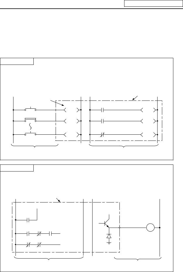
12.1 Example of Faulty Circuit ………………………………………………………………. |
299 |
1. System Configuration
1. System Configuration
1.1 System Configuration for PLC Development
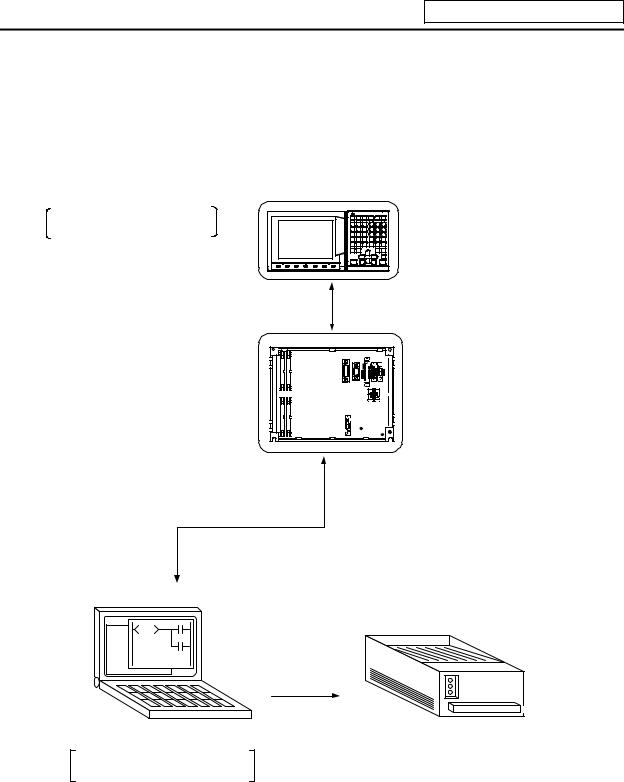
The system configuration for PLC development is shown below.
Ladder editing, ladder monitor and PLC RUN/STOP, etc.
A new development is possible with the personal computer.
|
and |
Unit |
|
Settinging and DisplaDisplayUnit |
The ladder is developed using the setting and display unit. (Onboard development)
BaseI/OI/OUnitUnit
To connector RS-232C
RS-232C
Up/downloading is carried out with the personal computer’s development tool.
Personal computer
General printer
Used for ladder development, creating message, ladder monitor and saving data.
(Note) Refer to the «PLC Onboard Instruction Manual» (IB-1500179) for edition using the setting and display unit (onboard edition), and the «PLC Development Software Manual (MELSEC Tool Section)» (IB-1500177) for development using the personal computer.
— 1 —
1. System Configuration
1.2 User PLC (Ladder) Development Procedure
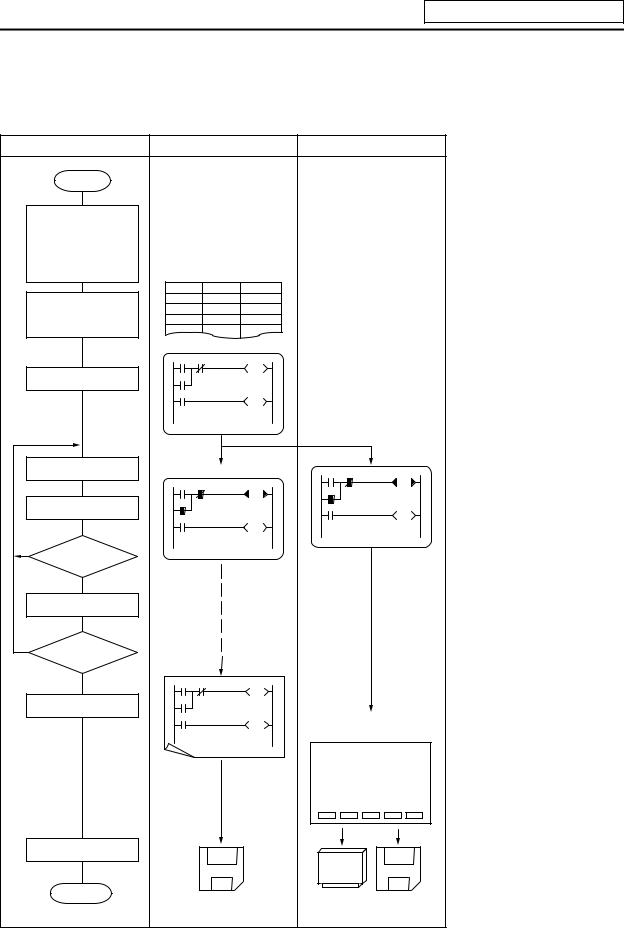
The procedure for creating the user PLC, used to control the control target (machine) built into the control unit, is shown below.
|
Procedure |
Personal |
Computer |
CNC Unit |
|||||
|
Start |
||||||||
|
Determination of |
||||||||
|
machine |
||||||||
|
Determination of |
||||||||
|
CNC and PLC |
||||||||
|
specifications |
Commercially available |
|||||||
|
Determination of the |
||||||||
|
numbers of I/O points |
spreadsheet tool |
|||||||
|
Assignment of I/O |
Device |
Name |
Comment |
|||||
|
X0 |
X-OT |
X-axis OT |
||||||
|
signals |
X1 |
Y-OT |
Y-axis OT |
|||||
|
Assignment of |
X2 |
Z-OT |
Z-axis OT |
|||||
|
internal relays |
GX Developer |
|||||||
|
Programming |
||||||||
|
Debugging operation |
GX Developer |
Onboard |
||||||
|
Program correction |
||||||||
|
Is debugging |
||||||||
|
NO |
complete? |
|||||||
|
YES |
||||||||
|
Test operation by |
||||||||
|
CNC unit |
||||||||
|
Is test operation |
||||||||
|
NO |
OK? |
GX Developer |
||||||
|
YES |
||||||||
|
Printout |
||||||||
|
BACKUP screen |
||||||||
|
DATA IN/OUT screen |
||||||||
|
[BACKUP] |
PARAM 3.2/2 |
|||||||
|
#1 BACKUP |
####### |
|||||||
|
#2 RESTORE |
######### |
|||||||
|
#( ) ( |
) |
|||||||
|
Data save |
||||||||
|
Com pletion |
Program data |
Memory cassette Binary |
||||||
|
data |
||||||||
|
(F-ROM) |
||||||||
|
— 2 — |
The data created with the commercially available spreadsheet tool can be used as ladder comment data.
Use GX Developer for programming.
After completion, download the data through RS-232C.
Perform monitoring/correction with GX Developer’s online function or onboard function.
Printout to a commercial printer connected with the personal computer from GX Developer.
Excute the ROM backup operation on the BACKUP screen.
Excute the binary data output on the DATA IN/OUT screen.
Program data:
Saved using GX Developer
Binary data:
Saved using DATA IN/OUT screen
2. PLC Processing Program
2. PLC Processing Program
2.1 PLC Processing Program Level and Operation
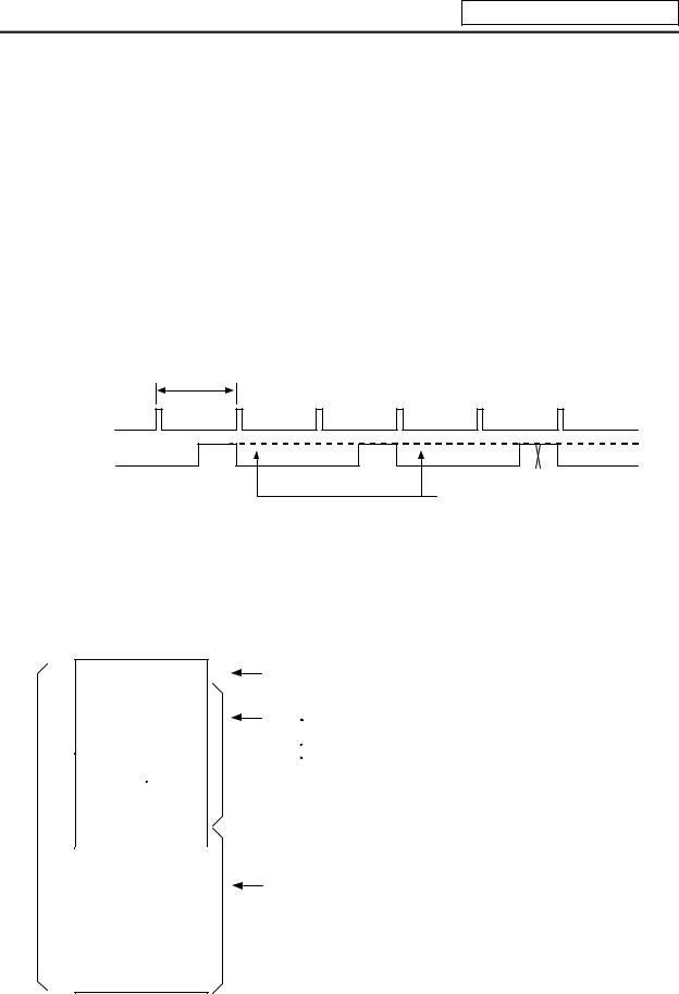
Table 2.1-1 explains the contents of users PLC processing level and Fig. 2.1-1 shows the timing chart.
|
Table 2.1-1 PLC processing level |
|
|
Program name |
Description (frequency, level, etc.) |
|
High-speed processing |
This program starts periodically with a time interval of 7.1ms. |
|
program |
This program has the highest level as a program that starts periodically. |
|
It is used in signal processing where high-speed processing is required. |
|
|
Processing time of this program shall not exceed 0.5ms. |
|
|
Application example: |
|
|
Position count control of turret and ATC magazine |
|
|
Main processing |
This program runs constantly. When one ladder has been executed from |
|
program (ladder) |
the head to END, the cycle starts again at the head. |
7.1ms
High-speed processing
Main processing
(Note 1)
This section is used by the controller.
(Note 1) The section from the END command to the next scan is done immediately as shown with the X section. Note that the min. scan time will be 14.2ms.
Fig. 2.1-1 PLC processing program operation timing chart
2.2 User Memory Area Configuration
The user memory area approximate configuration and size are shown below.
|
Control information |
|||||
|
Message data |
|||||
|
Contact coil |
|||||
|
User PLC |
|||||
|
code area |
comment data |
||||
|
P251 |
|||||
|
High-speed processing |
|||||
|
P252 |
Main Processing
Max. 256Kbyte from control information to messages.
Internal information table of User PLC (The table is automatically generated.)
Data excepting the ladder program Alarm messages
 Operator messages PLC switches
Load meter
 Contact
  coil comment data, etc.
(Each of them can be stored in two languages.)
Total 127Kbyte
Program with the ladder language
Programs excepting the main processing are not necessary.
The program order of initial, high-speed and main processing is random.
Total 4000 steps
— 3 —
![]()
3. Input/Output Signals
3. Input/Output Signals
3.1 Input/Output Signal Types and Processing
The input/output signals handled in user PLC are as follows:
(1)Input/output from/to controller
(2)Input/output from/to operation board (Note 1)
(3)Input/output from/to machine
The user PLC does not directly input or output these signals from or to hardware or controller; it inputs or outputs the signals from or to input/output image memory. For the reading and writing with the hardware or controller, the controller will perform the input/output according to the level of the main process or high-speed process.
|
Controller |
|||||||||
|
Input/output image |
|||||||||
|
Operation |
Controller |
User PLC |
|||||||
|
memory |
|||||||||
|
board |
|||||||||
|
(device X, Y) |
|||||||||
|
Machine |
|||||||||
(Note 1) The operation board here refers to when the remote I/O unit is installed on the communication terminal.
Fig. 3.1-1 Concept of input/output processing
High-speed processing input/output
The controller reads the high-speed input designation input, and
sets in the im age m em ory.
P251
User PLC high -speed processing
The controller outputs the high-speed output designation output from the im age mem ory to the m achine.
Main processing input/output
The controller reads the
input other than the high-speed input designation,
and sets in the im age memory.
P252
User PLC m ain processing
The controller outputs the output other than the high-speed output designation from the
image m em ory to the m achine.
Fig. 3.1-2 Input/output processing conforming to program level
— 4 —
3. Input/Output Signals
Table 3.1-1 lists whether or not high-speed input/output, interrupt input and initial processing can be performed.
Table 3.1-1 Whether or not high-speed input/output, interrupt input and initial can be performed
|
High-speed input |
High-speed output |
||
|
specification |
specification |
||
|
Input signal from control unit |
x |
x |
|
|
Output signal to control unit |
x |
x |
|
|
Input signal from machine |
(2-byte units) |
x |
|
|
Output signal to machine |
x |
(2-byte units) |
|
|
Input signal from operation board |
x |
x |
|
|
Output signal to operation board |
x |
x |
|
|
: Possible |
x : Not possible |
The operation board in Table 3.1-1 is applied when control is performed by operation board input/output card that can be added as NC option.
3.2 Handling of Input Signals Designated for High-Speed Input
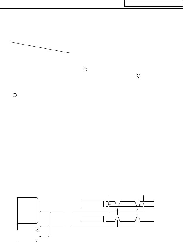
The input/output signals used in user PLC are input/output for each program level as shown in Fig. 3.1-2.
In high-speed processing, input/output signal for which high-speed input or output designation (parameter) is made is input or output each time the high-speed processing program runs. In main processing, signals other than interrupt input signals or high-speed input/output designation are input/output.
When high-speed input designation signal is used in main processing, the input signal may change within one scan because high-speed processing whose level is higher than main processing interrupts. Input signal which must not change within one scan should be saved in temporary memory (M), etc., at the head of main processing and the temporary memory should be used in the main program, for example.
Input image memory
 PLC one scan
|
Main |
A |
B |
A |
|
processing |
|||
|
(1) |
High-speed processing
(2)
(1) Set at the head of main processing.
(2) Set at the head of high-speed processing.
The hatched area is high-speed input designation part. Whenever the high-speed processing program runs, data is reset in the hatched area. Thus, the signal in the hatched area may change in main processing (A) and (B) because the high-speed process interrupts between (A) and (B) and re-reads the input signal in the hatched area.
— 5 —
3. Input/Output Signals
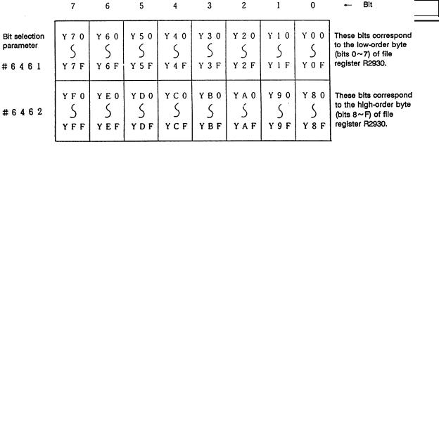
3.3 High-Speed Input/output Designation Method
High-speed input/output is designated by setting the corresponding bit of the bit selection parameter as shown below.
(1) High-speed input designation
(2) High-speed output designation
·As listed above, one bit corresponds to two bytes (16 points).
·Input or output in which 1 is set in the table is not performed at the main processing program level.
·Although the number of bits set to 1 is not limited, set only necessary ones from viewpoint of overhead.
·High-speed input/output designation corresponds to the bit selection parameter and can be set in the parameter. However, it is recommended to set in a sequence program to prevent a parameter setting error, etc.
Example: —[MOV H3 R2928]— ….. To designate X00~X0F, X10~X1F (bit 0 and 1 for H3)
— 6 —
3. Input/Output Signals
3.4 Limits for Using High Speed Processing Program
3.4.1Separation of Main Processing and High Speed Processing Bit Operation Areas
(1)Bit operation area
When using high speed processing, the bit operation range such as the temporary memory is separated from the main process.
(Method 1) When using the same M or G code, the bit operation area for high speed processing and the bit operation area for main processing are separated by 64 points or more and used.
|
For example, the following is used |
|
|
M0 to M4735 for main processing |
Separate by 64 points or more |
|
M4800 to M5120 for high speed processing |
(M4736 to M4799 are not used) |
(Method 2) M is used for the main processing temporary memory and G is used for the high speed processing temporary memory.
(Note 1) The output devices handled with high speed processing must be limited to M or Y, D and R.
(Note 2) These limits apply not only to the OUT command, but also to the PLF, PLS, SET, RST and MOV command, etc., outputs. The devices apply to all devices including M, F, L, SM, T and C.
Interlock
Output to NC
Separated by 64 points or mpre during the MOV command.
— 7 —
3. Input/Output Signals
(2)Data area
Even with commands that handle data (numerical values) during the MOV command, etc., the bit area must be separated by 64 points or more and the data register (D) and file register (R) separated by four registers or more.
|
Example) Use D0 to D896 for main processing |
Separate by four registers or more |
|
|
Use D900 to D1023 for high speed processing |
||
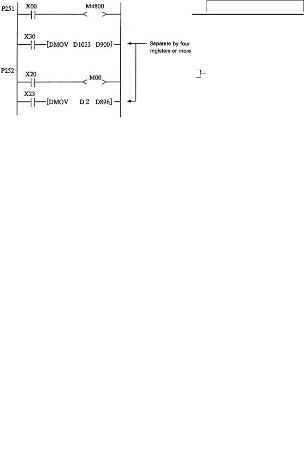
3.4.2 Separation of Remote I/O Output
When handling high speed output during the high speed process, the main processing output and high speed processing output cannot be used together in the same remote I/O unit (32 points in channel No. setting rotary switch). A separate 32 points for high speed processing output or a 16-point remote I/O unit will be required.
MOV commands, etc., that extend over differing remote I/O units must not be enforced during either main processing or high speed processing. If these must be enforced, the channel No. setting rotary switch for the output unit used in the main processing and the output unit used for the high speed processing must be set 1 or more apart.
M10
— 8 —
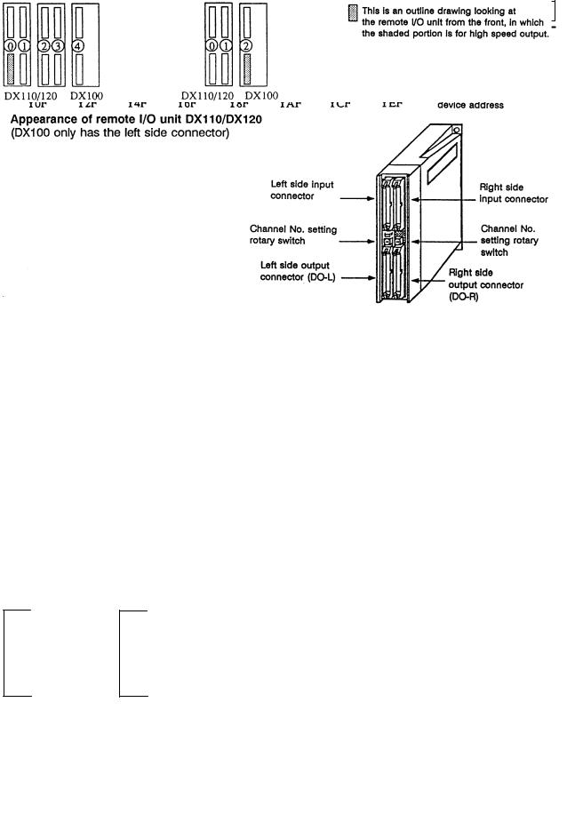
3. Input/Output Signals
(Usage example 1) Avoid interference with the main process by assigning 7 (last channel) for the channel No. rotary switch for high speed processing output.
For example, use YE0 to YFF (for 32-point DO-L) or YE0 to YEF (for 16-point DO-R) as the high speed processing output.
(Refer to <Usage examples 1-1, 1-2 and 1-3> below.)
(Usage example 2) Assign Y0 to Y1F (32-point) for high speed processing, and use Y20 and following for the main process.
(Refer to <Usage example 2> below.)
(Usage example 3) Assign the device after the device used for main processing for the high speed process.
For example, if the devices up to Y2D are used for the main process, use Y40 to Y5F (channel No. setting rotary switch No.: 2) for the high speed process. (Refer to <Usage example 3> below.)
Relation of channel No. setting switch and device No.
|
<Usage example 1-1> |
<Usage example 1-2> |
(Devices are YE0 and following)
Usage examples 1-2 show the assignment for the 16-point unit as the No. of high speed output points is relatively low.
|
DX35*/45* DX100 |
DX35*/45* DX110/120 |
||||||||||||
|
<Usage example 2> |
<Usage example 3> |
||||||||||||
|
DX35*/45* DX100 DX100 |
DX35*/45* DX100 |
|
|
/120 |
||
— 9 —
4. Parameters
4. Parameters
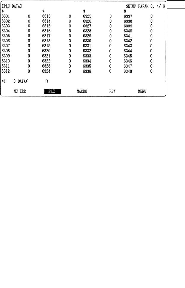
4.1 PLC Constants
The parameters that can be used in user PLC include PLC constants set in the data type.
Set up data is stored in a file register and is backed up. In contrast, if data is stored in the file register corresponding to PLC constant by using sequence program MOV instruction, etc., it is backed up. However, display remains unchanged. Display another screen once and then select the screen again.
48 PLC constants are set (the setting range is ±8 digits). (Signed 4-byte binary data)
The correspondence between the PLC constants and file registers is listed below. The setting and display screens are also shown.
|
# |
Corresponding file registers |
# |
Corresponding file registers |
# |
Corresponding file registers |
|||||
|
High order |
Low order |
High order |
Low order |
High order |
Low order |
|||||
|
6301 |
R2801 |
R2800 |
6321 |
R2841 |
R2840 |
6341 |
R2881 |
R2880 |
||
|
6302 |
R2803 |
R2802 |
6322 |
R2843 |
R2842 |
6342 |
R2883 |
R2882 |
||
|
6303 |
R2805 |
R2804 |
6323 |
R2845 |
R2844 |
6343 |
R2885 |
R2884 |
||
|
6304 |
R2807 |
R2806 |
6324 |
R2847 |
R2846 |
6344 |
R2887 |
R2886 |
||
|
6305 |
R2809 |
R2808 |
6325 |
R2849 |
R2848 |
6345 |
R2889 |
R2888 |
||
|
6306 |
R2811 |
R2810 |
6326 |
R2851 |
R2850 |
6346 |
R2891 |
R2890 |
||
|
6307 |
R2813 |
R2812 |
6327 |
R2853 |
R2852 |
6347 |
R2893 |
R2892 |
||
|
6308 |
R2815 |
R1814 |
6328 |
R2855 |
R2854 |
6348 |
R2895 |
R2894 |
||
|
6309 |
R2817 |
R2816 |
6329 |
R2857 |
R2856 |
|||||
|
6310 |
R2819 |
R2818 |
6330 |
R2859 |
R2858 |
|||||
|
6311 |
R2821 |
R2820 |
6331 |
R2861 |
R2860 |
|||||
|
6312 |
R2823 |
R2822 |
6322 |
R2863 |
R2862 |
|||||
|
6313 |
R2825 |
R2824 |
6333 |
R2865 |
R2864 |
|||||
|
6314 |
R2827 |
R2826 |
6334 |
R2867 |
R2866 |
|||||
|
6315 |
R2829 |
R2828 |
6335 |
R2869 |
R2868 |
|||||
|
6316 |
R2831 |
R2830 |
6336 |
R2871 |
R2870 |
|||||
|
6317 |
R2833 |
R2832 |
6337 |
R2873 |
R2872 |
|||||
|
6318 |
R2835 |
R2834 |
6338 |
R2875 |
R2874 |
|||||
|
6319 |
R2837 |
R2836 |
6339 |
R2877 |
R2876 |
|||||
|
6320 |
R2839 |
R2838 |
6340 |
R2879 |
R2878 |
PLC constant screen
— 10 —

4. Parameters
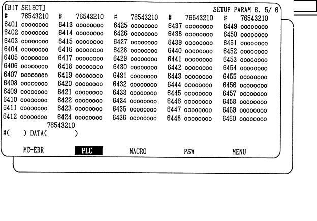
4.2 Bit Selection Parameters
The parameters that can be used in user PLC include bit selection parameters set in the bit type. Set up data is stored in a file register and is backed up.
For use in bit operation in a sequence program, the file register contents are transferred to temporary memory (M) using the MOV command. In contrast, if data is stored in the file register corresponding to bit selection by using the MOV command etc., it is backed up. However, display remains unchanged. Once display another screen and again select screen.
The corresponding between the bit selection parameters and file registers is listed below. The setting and display screens are also shown.
|
# |
Corresponding |
# |
Corresponding |
# |
Corresponding |
# |
Corresponding |
|||
|
file register |
file register |
file register |
file register |
|||||||
|
6401 |
R2900-LOW |
6433 |
R2916-LOW |
6449 |
R2924-LOW |
6481 |
R2940-LOW |
|||
|
6402 |
R2900-HIGH |
6434 |
R2916-HIGH |
6450 |
R2924-HIGH |
6482 |
R2940-HIGH |
|||
|
6403 |
R2901-L |
6435 |
R2917-L |
6451 |
R2925-L |
6483 |
R2941-L |
|||
|
6404 |
R2901-H |
6436 |
R2917-H |
6452 |
R2925-H |
6484 |
R2941-H |
|||
|
6405 |
R2902-L |
6437 |
R2918-L |
6453 |
R2926-L |
6485 |
R2942-L |
|||
|
6406 |
R2902-H |
6438 |
R2918-H |
6454 |
R2926-H |
6486 |
R2942-H |
|||
|
6407 |
R2903-L |
6439 |
R2919-L |
6455 |
R2927-L |
6487 |
R2943-L |
|||
|
6408 |
R2903-H |
6440 |
R2919-H |
6456 |
R2927-H |
6488 |
R2943-H |
|||
|
6409 |
R2904-L |
6441 |
R2920-L |
6457 |
R2928-L |
6489 |
R2944-L |
|||
|
6410 |
R2904-H |
6442 |
R2920-H |
6458 |
R2928-H |
6490 |
R2944-H |
|||
|
6411 |
R2905-L |
6443 |
R2921-L |
6459 |
R2929-L |
6491 |
R2945-L |
|||
|
6412 |
R2905-H |
6444 |
R2921-H |
6460 |
R2929-H |
6492 |
R2945-H |
|||
|
6413 |
R2906-L |
6445 |
R2922-L |
6461 |
R2930-L |
6493 |
R2946-L |
|||
|
6414 |
R2906-H |
6446 |
R2922-H |
6462 |
R2930-H |
6494 |
R2946-H |
|||
|
6415 |
R2907-L |
6447 |
R2923-L |
6463 |
R2931-L |
6495 |
R2947-L |
|||
|
6416 |
R2907-H |
6448 |
R2923-H |
6464 |
R2931-H |
6496 |
R2947-H |
|||
|
6417 |
R2908-L |
Use bit selection |
6465 |
R2932-L |
Bit selection parameter |
|||||
|
6418 |
R2908-H |
parameters |
6466 |
R2932-H |
#6449~#6496 are PLC |
|||||
|
#6401~#6448 freely. |
operation selection |
|||||||||
|
6419 |
R2909-L |
6467 |
R2933-L |
|||||||
|
parameters used by the |
||||||||||
|
6420 |
R2909-H |
6468 |
R2933-H |
|||||||
|
machine manufacturer |
||||||||||
|
6421 |
R2910-L |
6469 |
R2934-L |
and MITSUBISHI. The |
||||||
|
6422 |
R2910-H |
6470 |
R2934-H |
contents are fixed. |
||||||
|
6423 |
R2911-L |
6471 |
R2935-L |
|||||||
|
6424 |
R2911-H |
6472 |
R2935-H |
|||||||
|
6425 |
R2912-L |
6473 |
R2936-L |
|||||||
|
6426 |
R2912-H |
6474 |
R2936-H |
|||||||
|
6427 |
R2913-L |
6475 |
R2937-L |
|||||||
|
6428 |
R2913-H |
6476 |
R2937-H |
|||||||
|
6429 |
R2914-L |
6477 |
R2938-L |
|||||||
|
6430 |
R2914-H |
6478 |
R2938-H |
|||||||
|
6431 |
R2915-L |
6479 |
R2939-L |
|||||||
|
6432 |
R2915-H |
6480 |
R2939-H |
— 11 —
4. Parameters
Bit selection screen
— 12 —
4. Parameters
Contents of bit selection parameters #6449~#6496
|
Symbol |
7 |
6 |
5 |
4 |
3 |
2 |
1 |
0 |
||||
|
name |
||||||||||||
|
#6449 |
NC card |
Setting |
Counter C |
Integrating |
PLC counter |
PLC timer |
||||||
|
Controller |
display unit |
|||||||||||
|
0 |
R2924 |
L |
thermal |
thermal |
— |
retention |
timer T |
program on |
program on |
|||
|
alarm on |
alarm on |
retention |
||||||||||
|
1 |
0 |
|||||||||||
|
#6450 |
External |
Alarm/ |
Full screen |
Operator |
||||||||
|
R2924 |
H |
alarm |
— |
R |
F |
Alarm |
||||||
|
1 |
operator |
display of |
message |
|||||||||
|
message |
system system message on |
|||||||||||
|
change |
message |
on |
||||||||||
|
display |
||||||||||||
|
#6451 |
GX-Developer |
PLC |
Onboard |
|||||||||
|
2 |
R2925 |
L |
— |
— |
communi- |
development |
editing not |
— |
Onboard on |
|||
|
environment |
possible |
|||||||||||
|
cation on |
||||||||||||
|
selection |
||||||||||||
|
#6452 |
GOT |
Counter |
Integrating |
|||||||||
|
R2925 |
H |
communi- |
timer |
|||||||||
|
3 |
— |
(fixed) |
— |
|||||||||
|
cation |
(fixed) |
|||||||||||
|
retention |
||||||||||||
|
connection |
retention |
|||||||||||
|
#6453 |
Message |
|||||||||||
|
R2926 |
L |
|||||||||||
|
4 |
— |
— |
— |
— |
— |
language |
||||||
|
change code |
||||||||||||
|
#6454 |
Equivalent of |
|||||||||||
|
5 |
R2926 |
H |
||||||||||
|
remote I/O 2ch |
||||||||||||
|
#6455 |
||||||||||||
|
6 |
R2927 |
L |
— |
— |
— |
— |
— |
— |
— |
— |
||
|
#6456 |
||||||||||||
|
7 |
R2927 |
H |
— |
— |
— |
— |
— |
— |
— |
— |
||
|
#6457 |
||||||||||||
|
8 |
R2928 |
L |
High-speed input specification 1 |
|||||||||
|
#6458 |
||||||||||||
|
9 |
R2928 |
H |
High-speed input specification 2 |
|||||||||
|
#6459 |
||||||||||||
|
A |
R2929 |
L |
High-speed input specification 3 |
(Spare) |
||||||||
|
#6460 |
||||||||||||
|
B |
R2929 |
H |
High-speed input specification 4 |
(Spare) |
||||||||
|
#6461 |
||||||||||||
|
C |
R2930 |
L |
High-speed output specification 1 |
|||||||||
|
#6462 |
||||||||||||
|
D |
R2930 |
H |
High-speed output specification 2 |
|||||||||
|
#6463 |
||||||||||||
|
E |
R2931 |
L |
High-speed output specification 3 |
(Spare) |
||||||||
|
#6464 |
||||||||||||
|
F |
R2931 |
H |
High-speed output specification 4 |
(Spare) |
||||||||
|
— 13 — |
![]()
4. Parameters
|
Symbol |
7 |
6 |
5 |
4 |
3 |
2 |
1 |
0 |
|||||
|
name |
|||||||||||||
|
0 |
#6465 |
— |
— |
— |
— |
— |
— |
— |
— |
||||
|
R2932 |
L |
||||||||||||
|
1 |
#6466 |
— |
— |
— |
— |
— |
— |
— |
— |
||||
|
R2932 |
H |
||||||||||||
|
2 |
#6467 |
— |
— |
— |
— |
— |
— |
— |
— |
||||
|
R2933 |
L |
||||||||||||
|
3 |
#6468 |
||||||||||||
|
R2933 |
H |
||||||||||||
|
#6469 |
|||||||||||||
|
MC alarm 4 |
|||||||||||||
|
4 |
Standard |
PLC |
— |
||||||||||
|
R2934 |
L |
parameter |
output off |
||||||||||
|
5 |
#6470 |
||||||||||||
|
R2934 |
H |
||||||||||||
|
#6471 |
|||||||||||||
|
6 |
— |
— |
— |
— |
— |
— |
— |
— |
|||||
|
R2935 |
L |
||||||||||||
|
#6472 |
|||||||||||||
|
7 |
— |
— |
— |
— |
— |
— |
— |
— |
|||||
|
R2935 |
H |
||||||||||||
|
8 |
#6473 |
— |
— |
||||||||||
|
R2936 |
L |
||||||||||||
|
9 |
#6474 |
||||||||||||
|
R2936 |
H |
||||||||||||
|
A |
#6475 |
||||||||||||
|
R2937 |
L |
||||||||||||
|
B |
#6476 |
||||||||||||
|
R2937 |
H |
||||||||||||
|
C |
#6477 |
||||||||||||
|
R2938 |
L |
||||||||||||
|
D |
#6478 |
||||||||||||
|
R2938 |
H |
||||||||||||
|
E |
#6479 |
||||||||||||
|
R2939 |
L |
||||||||||||
|
F |
#6480 |
||||||||||||
|
R2939 |
H |
||||||||||||
(Note 1) Be sure to set the bits indicated — and blanks to 0.
(Note 2) Parameters #6481 to #6496 are reserved for debugging by Mitsubishi.
— 14 —

5. Explanation of Devices
5. Explanation of Devices
5.1 Devices and Device Numbers
The devices are address symbols to identify signals handled in PLC. The device numbers are serial numbers assigned to the devices. The device numbers of devices X, Y and H are represented in hexadecimal notation. The device numbers of other devices are represented in decimal notation.
5.2 Device List
|
Device |
Device No. |
Unit |
Details |
|
|
X* |
X0~XABF |
(2752 points) |
1 bit |
Input signal to PLC. Machine input, etc. |
|
Y* |
Y0~YDEF |
(3584 points) |
1 bit |
Output signal from PLC. |
|
Machine output, etc. |
||||
|
M |
M0~M8191 |
(8192 points) |
1 bit |
Temporary memory |
|
F |
F0~F127 |
(128 points) |
1 bit |
Temporary memory, alarm message |
|
interface |
||||
|
L |
L0~L255 |
(256 points) |
1 bit |
Latch relay (backup memory) |
|
SM* |
SM0~SM127 (128 points) |
1 bit |
Special relay |
|
|
T |
T0~T15 |
(16 points) |
1 bit or 16 bits |
10ms unit timer |
|
T16~T95 |
(80 points) |
1 bit or 16 bits |
100ms unit timer |
|
|
T96~T103 |
(8 points) |
1 bit or 16 bits |
100ms unit integrating timer |
|
|
C |
C0~C23 |
(24 points) |
1 bit or 16 bits |
Counter |
|
D |
D0~D1023 |
(1024 points) |
16 bits or 32 bits |
Data register for arithmetic operation |
|
R* |
R0~R8191 |
(8192 points) |
16 bits or 32 bits |
File register. R500 to R549 and R1900 to |
|
R2799 are released to the user for interface |
||||
|
between the PLC and controller. R1900 to |
||||
|
R2799 are backed up by the battery. |
||||
|
Z |
Z0~Z1 |
(2 points) |
16 bits |
Index of D or R address (±n) |
|
N |
N0~N7 |
(8 points) |
— |
Master control nesting level |
|
P* |
P0~P255 |
(256 points) |
— |
Label for conditional jump and subroutine |
|
call |
||||
|
K |
K-32768~K32767 |
— |
Decimal constant for 16-bit command |
|
|
K-2147483648~ |
— |
Decimal constant for 32-bit command |
||
|
K2147483647 |
||||
|
H |
H0~HFFFF |
— |
Hexadecimal constant for 16-bit command |
|
|
H0~HFFFFFFFF |
— |
Hexadecimal constant for 32-bit command |
(Note 1) The applications of the devices having a * in the device column are separately determined. Do not use the undefined device Nos., even if they are open.
(Note 2) When using temporary memory such as M device, separate READ and WRITE every 8bits.
— 15 —
5. Explanation of Devices
5.3 Detailed Explanation of Devices
5.3.1 Input/output X, Y
Input/output X and Y are a window for executing communication with the PLC and external device or CNC.
Input X
(a)This issued commands or data from an external device such as a push-button, changeover switch, limit switch or digital switch to the PLC.
(b)Assuming that there is a hypothetical relay Xn built-in the PLC per input point, the program uses the «A» contact and «B» contact of that Xn.
(c)There is no limit to the No. of «A» contacts and «B» contacts of the input Xn that can be used in the program.
|
Hypothetical |
relay |
PLC |
|
PB1 |
X10 |
X10 |
|
LS2 |
X11 |
X11 |
|
PB16 |
X1F |
X1F |
(d) The input No. is expressed with a hexadecimal.
Output Y
(a)This outputs the results of the program control to the solenoid, magnetic switch, signal lamp or digital indicator, etc.
(b)The output can be retrieved with the equivalent of one «A» contact.
(c)There is no limit to the No. of «A» contacts and «B» contacts of the output Yn that can be used in the program.
PLC
Y10


 24V Y10
Load
Y10
Y10
(d)The output No. is expressed with a hexadecimal.
—16 —

5. Explanation of Devices
5.3.2 Internal Relays M and F, Latch Relay L
The internal relay and latch relay are auxiliary relays in the PLC that cannot directly output to an external source.
Internal relays M
(a)These relays are cleared when the power is turned OFF.
(b)There is no limit to the No. of «A» contacts and «B» contacts of the internal relays that can be used in the program.
(c)The internal relay No. is expressed with a decimal.
Internal relay F
Internal relay F is an interface for the alarm message display.
Use the bit selection parameter to determine whether to use this relay for the alarm message interface. The target will be F0 to F127. This internal relay can be used in the same manner as the internal relay M when not used as the alarm message interface.
Latch relay L
(a)The original state is held even when the power is turned OFF.
(b)There is no limit to the No. of «A» contacts and «B» contacts of the latch relay that can be used in the program.
(c)The latch No. is expressed with a decimal.
5.3.3 Special Relays SM
The special relays are relays having fixed applications such as the carrier flag for operation results and the display request signal to the setting and display unit. Even the relays of SM0 to SM127 that are not currently used must not be used as temporary memory.
Special relays SM
(a)This relay is cleared when the power is turned OFF.
(b)There is no limit to the No. of «A» contacts and «B» contacts of the special relays that can be used in the program.
(c)The special relay No. is expressed with a decimal.
— 17 —
5. Explanation of Devices
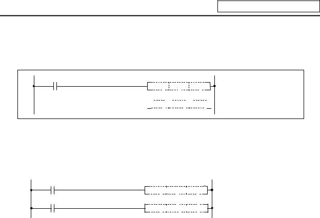
5.3.4Timer T
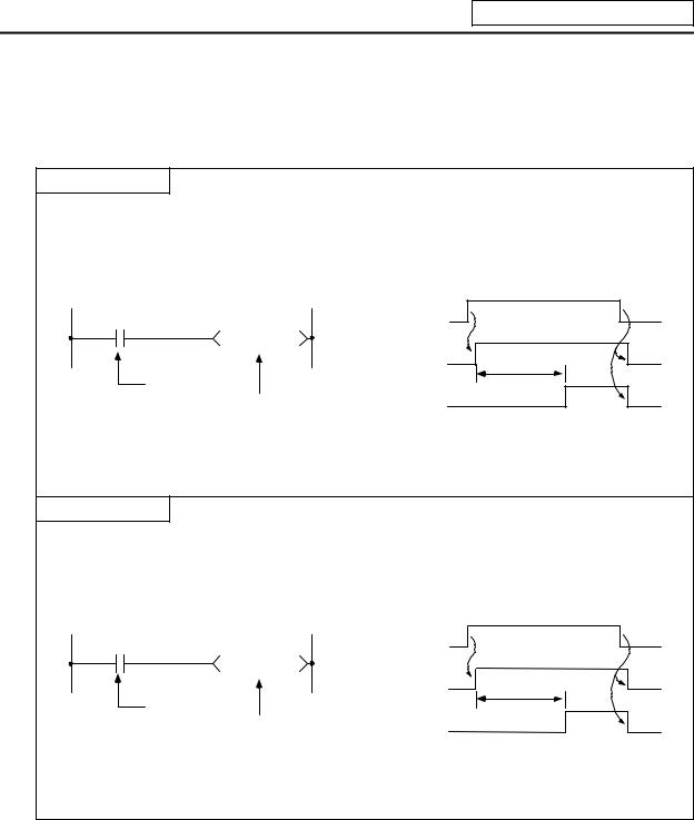
(1)The 100ms timer, 10ms timer and 100ms integrated timer are available for this count-up type timer.
100ms Timer T
(a)When the input conditions are set, the count starts. When the set value is counted, that timer contact will turn ON.
(b)If the input conditions are turned OFF, the 100ms timer count value will be set to 0, and the contact will turn OFF.
|
ON |
||||
|
X5 |
X5 |
OFF |
ON |
|
|
T57 K50 |
||||
|
T57 coll |
OFF |
5 seconds |
||
|
Input conditions |
||||
|
ON |
||||
|
100ms timer |
T57 contact |
OFF |
||
(c)When #6449 bit0=1, the value is set with a decimal (Kn), and can be designated from 1 to 32767 (0.1 to 3276.7 s). The data register (D) data can also be used as the setting value. File register (R) cannot be used.
10ms Timer T
(a)When the input conditions are set, the count starts. When the set value is counted, that timer contact will turn ON.
(b)If the input conditions are turned OFF, the 10ms timer count value will be set to 0, and the contact will turn OFF.
|
ON |
|||||
|
X5 |
X5 |
OFF |
ON |
||
|
T1 |
K500 |
||||
|
T1 coll |
OFF |
5 seconds |
|||
|
Input |
conditions |
ON |
|||
|
10ms timer |
T1 contact |
OFF |
|||
(c)When #6449 bit0=1, the value is set with a decimal (Kn), and can be designated from 1 to 32767 (0.01 to 327.67 s). The data register (D) data can also be used as the setting value. File register (R) cannot be used.
— 18 —
5. Explanation of Devices
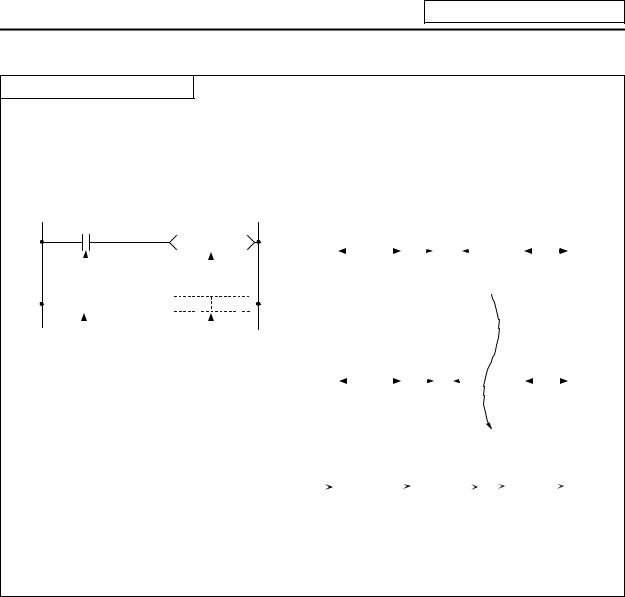
100ms integrated timer T
(a)When the input conditions are set, the count starts. When the set value is counted, that timer contact will turn ON.
(b)Even the input conditions are turned OFF, the 100ms integrated timer current value (count value) will be held, and the contact state will not change.
(c)The 100ms integrated timer count value will be set to 0 and the contact will turn OFF when the RST command is executed.
|
X5 |
ON |
|||||||||||||||||||||||||||||||||||||||||
|
T233 K100 |
X5 OFF |
9 seconds |
||||||||||||||||||||||||||||||||||||||||
|
Input conditions |
seconds |
|||||||||||||||||||||||||||||||||||||||||
|
1.5 seconds |
6 |
|||||||||||||||||||||||||||||||||||||||||
|
X7 |
100ms cumulative |
timer |
ON |
|||||||||||||||||||||||||||||||||||||||
|
RST T233 |
X7 OFF |
|||||||||||||||||||||||||||||||||||||||||
|
Reset input |
T233 reset command |
ON |
||||||||||||||||||||||||||||||||||||||||
|
T233 coll |
OFF |
9 seconds |
||||||||||||||||||||||||||||||||||||||||
|
1 |
6 |
seconds |
||||||||||||||||||||||||||||||||||||||||
|
seconds |
||||||||||||||||||||||||||||||||||||||||||
|
ON |
||||||||||||||||||||||||||||||||||||||||||
|
T233 contact OFF |
||||||||||||||||||||||||||||||||||||||||||
|
T233 current value |
0 |
1 |
~ 90 |
91~ 100 |
0 |
1 ~ 60 |
||||||||||||||||||||||||||||||||||||
(d)When #6449 bit0=1, the value is set with a decimal (Kn), and can be designated from 1 to 32767 (0.1 to 3267.7 s). The data register (D) data can also be used as the setting value. File register (R) cannot be used.
(e)When the bit selection parameter (#6449 bit2=1) is set, the 100ms integrated timer current value (count value) will be held even when the power is turned OFF.
(2)With the device T, the contact • coil is handled as bit device, and the current value is handled as word device. In the function commands described after, the word device T indicates the current value even if there is no description about it.
(3)When #6449 bit0=0 is set, timer value can be specified with the parameter set in the setting and display unit. At this time, the relationship between timer device and parameter is as shown below.
|
Device |
Parameter |
|
T0 to T15 |
#6000 to #6015 |
|
T56 to T135 |
#6016 to #6095 |
|
T232 to T239 |
#6096 to #6103 |
(Note 1) T16 to T55, T136 to T231, and T240 to T255 are specified with a program (Kn) regardless of #6449 bit0.
(Note2) Even when #6449 bit0=0, Kn is required for a sequence program. Note that, however, the Kn value is invalid.
(Note 3) When the data register (D) is used as setting value, the data register (D) details will be the setting value regardless of #6449 bit0.
— 19 —
5. Explanation of Devices
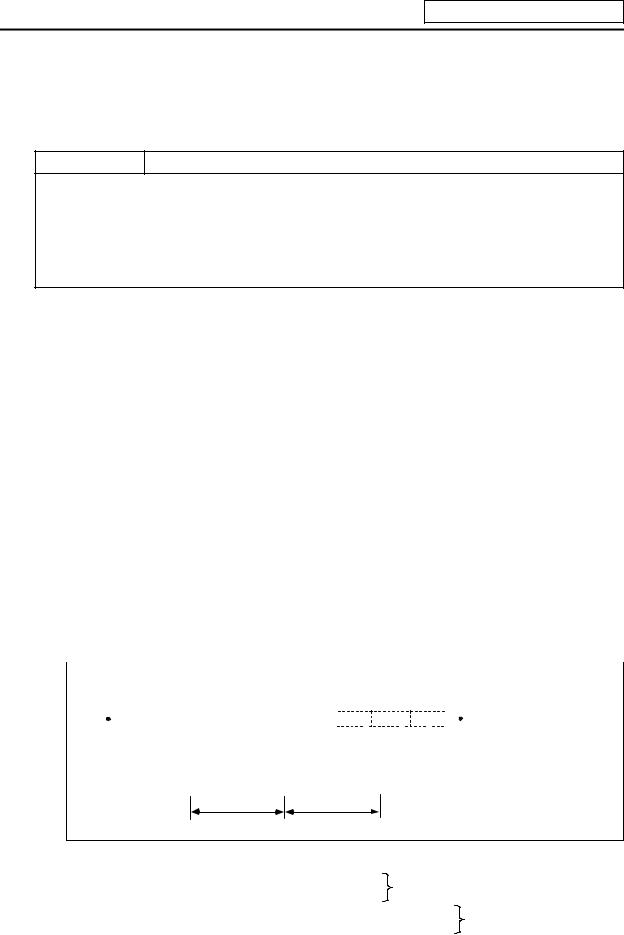
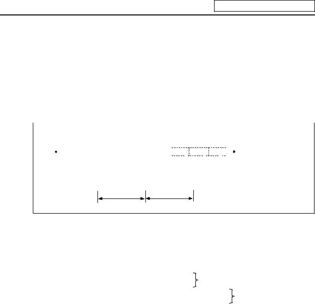
5.3.5Counter C
(1)The counter counts up and detects the rising edge of the input conditions. Thus, the count will not take place when the input conditions are ON.
Counter C
(a)The value is set with a decimal, and can be designated from 1 to 32767. The data register (D) data can also be used as the setting value. File register (R) cannot be used.
(b)The counter count value will not be cleared even if the input conditions turn OFF. The counter count value must be cleared with the RST command.
(c)When the bit selection parameter is set, the counter current value (count value) will be held even when the power is turned OFF. Note that some can not be held depending on the version of CNC.
(2)With the device C, the contact • coil is handled as bit device, and the current value (counter value) is handled as word device. In the function commands described after, the word device C indicates the current value (counter value) even if there is no description about it.
(3)The counter setting value can be set with the setting and display unit using device C. (Variable counter)
Whether the setting value (Kn) programmed with the sequence program or the setting value set from the setting and display unit is valid is selected with the bit selection parameters. The changeover is made in a group for C0 to C23. Even when set from the setting and display unit, the setting value (Kn) program will be required in the sequence program. However, the Kn value will be ignored. When the data register (D) is used for the setting value, the data register (D) details will be used as the setting value regardless of the parameter.
(Note) The setting value for device C24 to C127 of counter C cannot be set from the setting and display unit.
5.3.6Data Register D
(1)The data register is the memory that stores the data in the PLC.
(2)The data register has a 1-point 16-bit configuration, and can be read and written in 16-bit units. To handle 32-bit data, two points must be used. The data register No. designated with the 32-bit command will be the low-order 16-bit, and the designated data register No. +1 will be the high-order 16-bit.
|
Circuit example |
||||||||||||||||
|
The X0 to 1F data is |
||||||||||||||||
|
0 |
DMOV K8X0 |
D0 |
||||||||||||||
|
stored in D0,1. |
||||||||||||||||
|
Data storage |
||||||||||||||||
|
D1 |
D0 |
|||||||||||||||
Higth-order 16-bit Low-order 16-bit
(X1F~X10) (XF~X0)
(3)The data that is stored once in the sequence program is held until other data is stored.
(4)The data stored in the data register is cleared when the power is turned OFF.
|
(5) Values that can be stored: Decimal -32768 to 32767 |
For 16-bit command |
|
|
Hexadecimal 0 to FFFF |
(Using Dn) |
|
|
Decimal -2147483648 to 2147483647 |
For 32-bit command |
|
|
Hexadecimal 0 to FFFFFFFF |
(Using Dn+1, Dn) |
(6)Data registers D0 to D1023 are all user release data registers.
—20 —
5. Explanation of Devices
5.3.7File Register R
(1)As with the data registers, the file registers are memories used to store data. However, there are some that have fixed applications, and those that are released.
(2)The file register has a 1-point 16-bit configuration, and can be read and written in 16-bit units. To handle 32-bit data, two points must be used. The file register No. designated with the 32-bit command will be the low-order 16-bit, and the designated file register No. +1 will be the high-order 16-bit.
(Example) Use of the DMOV command is shown below.
|
Circuit example |
||||||||||||||
|
The X0 to 1F data is |
||||||||||||||
|
0 |
DMOV K8X0 |
R0 |
||||||||||||
|
stored in R0,1. |
||||||||||||||
|
Data storage |
||||||||||||||
|
R1 |
R0 |
|||||||||||||
Higth-order 16-bit Low-order 16-bit
(X1F~X10) (XF~X0)
(3)The data that is stored once in the sequence program is held until other data is stored.
(4)With the file registers, the following registers are the user release.
R500 to R549, R1900 to R2799
The following registers of the registers above are not cleared when the power is turned OFF. R1900 to R2799
The other file registers have fixed applications such as interface of the PLC and CNC, parameter
|
interface, etc. |
||
|
(5) Values that can be stored: Decimal -32768 to 32767 |
For 16-bit command |
|
|
Hexadecimal 0 to FFFF |
(Using Dn) |
|
|
Decimal -2147483648 to 2147483647 |
For 32-bit command |
|
|
Hexadecimal 0 to FFFFFFFF |
(Using Dn+1, Dn) |
— 21 —
5. Explanation of Devices
5.3.8Index Registers Z
(1)The index registers are used as ornaments for the device (T, C, D, R).
165 


 MOV
MOV

 K4X0
K4X0

 D5Z0
D5Z0
 D5Z0 Indicates D (5+Z) = D8
(2)The index register has a 1-point 16-bit configuration, and can be read and written in 16-bit units.
(3)The data stored in the index register is cleared when the power is turned OFF.
(4)Values that can be stored: Decimal -32768 to 32767
Hexadecimal 0 to FFFF
(Note) The CRT display of the index registers Z is as shown below.
MOV  K3
K3  Z0
Z0
K4 Z0
MOV  X0
X0  D5
D5
— 22 —
5. Explanation of Devices
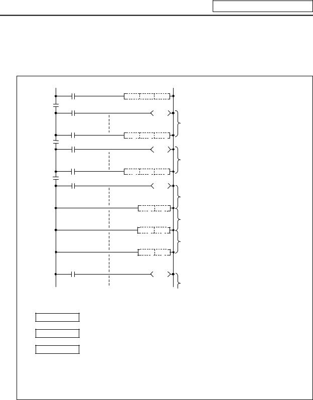
5.3.9Nesting N
(1)This indicates the master control nesting structure.
(2)The master control nesting (N) is used in order from smallest number.
|
A |
|||
|
MC N0 |
M15 |
||
|
N0 |
M15 |
||
|
B |
Execute when A conditions are set. |
||
|
MC N1 M16 |
|||
|
N1 |
M16 |
||
|
C |
Execute when A,B conditions are set. |
||
|
N2 |
MC N2 M17 |
||
|
M17 |
|||
|
Execute when A,B,C conditions are set. |
|||
|
MCR |
N2 |
Reset MC2 to 7 |
|
|
Execute when A,B conditions are set. |
|||
|
MCR |
N1 |
Reset MC1 to 7 |
|
|
Execute when A conditions are set. |
|||
|
MCR |
N0 |
Reset MC0 to 7 |
|
|
Execute regardless of A,B,C conditions. |
(a)The conditions for each master control to turn ON are as follow. MC N0 M15 ………. ON when condition A is ON
MC N1 M16 ………. ON when conditions A, B are ON MC N2 M17 ………. ON when conditions A, B, C are ON
(b)The timer and counter when the master control is OFF is as follows.
|
· 100ms timer, 10ms timer |
: The count value is set to 0. |
|
· 100ms integrated timer |
: The current count value is retained. |
|
· Counter |
: The current counter value is retained. |
|
· OUT command |
: All turn OFF. |
— 23 —
![]()
5. Explanation of Devices
5.3.10Pointer P
(1)The pointer indicates the branch command (CJ, CALL) jump destination. The pointer No. assigned at the jump destination head is called the label.
(2)Pointers P0 to P159, P251, P252, P255 are user release pointers.
(3)P255 always indicates END.
(P255 can be used as a device for CJ command, etc, but cannot be used as a label. This cannot be used for the CALL command device.)
|
Pointer |
||||
|
X13 |
Jump to label |
|||
|
33 |
CJ |
P20 |
||
|
P20 (step 501) |
||||
|
Label |
36 |
when X13 turns ON. |
||
|
P20 |
||||
|
501 |
||||
|
X17 |
Jump to END when |
|||
|
723 |
CJ |
P255 |
||
|
X17 turns ON. |
||||
726
(4)The special usages of the pointers other than P255 are shown below. P251: Label for starting PLC high-speed processing program.
P252: Label for starting PLC main (ladder) processing program.
CAUTION
The PLC will not operate correctly if Notes 1 to 4 are not observed.
(Note 1) Do not omit P252 label even when there is only a PLC main processing program. (Note 2) P251 and P252 cannot be used as CJ or CALL command devices.
(Note 3) Do not create a program in which the P** in the PLC high-speed processing program is jumped to from the PLC main processing program.
(Note 4) The P** used as a CJ or CALL command device must also be programmed as a label.
— 24 —

5. Explanation of Devices
5.3.11Decimal Constant K
(1)The decimal constant can be used in the following ways.
(a)Timer counter setting value: Designate in the range of 1 to 32767.
(b)Pointer No.: 0 to 159
(c)Bit device digit designation: 1 to 8
(d)Basic command, function command, exclusive command value setting
·16-bit command: -32768 to 32767
·32-bit command: -2147483648 to 2147483647
(2)The decimal constant is stored in the binary value (binary) in the PLC.
5.3.12Hexadecimal Constant H
(1)The hexadecimal constant is used to designate the basic command, function command and exclusive command values.
· 16-bit command: 0 to FFFF
· 32-bit command: 0 to FFFFFFFF
— 25 —

6. Explanation of Commands
6. Explanation of Commands
6.1 Command List
6.1.1 Basic Commands
|
Class |
Process |
Command |
No. |
||||||||||||||||||||||||||
|
Symbol |
Process details |
of |
Page |
||||||||||||||||||||||||||
|
unit |
sign |
||||||||||||||||||||||||||||
|
steps |
|||||||||||||||||||||||||||||
|
LD |
Start of logic operation |
1 |
42 |
||||||||||||||||||||||||||
|
(A contact operation start) |
|||||||||||||||||||||||||||||
|
LDI |
Start of logic denial operation |
1 |
42 |
||||||||||||||||||||||||||
|
(B contact operation start) |
|||||||||||||||||||||||||||||
|
AND |
Logical AND |
1 |
44 |
||||||||||||||||||||||||||
|
(A contact serial connection) |
|||||||||||||||||||||||||||||
|
ANI |
Logical AND denial |
1 |
44 |
||||||||||||||||||||||||||
|
(B contact serial connection) |
|||||||||||||||||||||||||||||
|
OR |
Logical OR |
1 |
46 |
||||||||||||||||||||||||||
|
(A contact parallel connection) |
|||||||||||||||||||||||||||||
|
ORI |
Logical OR denial |
1 |
46 |
||||||||||||||||||||||||||
|
(B contact parallel connection) |
|||||||||||||||||||||||||||||
|
ANB |
AND between logical blocks (Serial |
1 |
48 |
||||||||||||||||||||||||||
|
connection between blocks) |
|||||||||||||||||||||||||||||
|
Basic |
ORB |
OR between logical blocks |
1 |
50 |
|||||||||||||||||||||||||
|
command |
Bit |
(Parallel connection between blocks) |
|||||||||||||||||||||||||||
|
OUT |
Device output |
1~3 |
52 |
||||||||||||||||||||||||||
|
SET |
SET |
D |
Device set |
1 |
58 |
||||||||||||||||||||||||
|
RST |
RST |
D |
Device reset |
1~2 |
60 |
||||||||||||||||||||||||
|
MC |
M n |
D |
Master control start |
2 |
62 |
||||||||||||||||||||||||
|
MCR |
MCR |
n |
Master control release |
1 |
62 |
||||||||||||||||||||||||
|
PLS |
Generate one cycle worth of pulses at rising |
||||||||||||||||||||||||||||
|
PLS |
D |
2 |
64 |
||||||||||||||||||||||||||
|
edge of input signal |
|||||||||||||||||||||||||||||
|
PLF |
PLF |
Generate one cycle worth of pulses at falling |
|||||||||||||||||||||||||||
|
D |
2 |
64 |
|||||||||||||||||||||||||||
|
edge of input signal |
|||||||||||||||||||||||||||||
|
SFT |
SFT |
D |
Device 1-bit shift |
4 |
66 |
||||||||||||||||||||||||
|
MPS |
Registration of logical operation result |
1 |
68 |
||||||||||||||||||||||||||
|
MRD |
MPS |
Read of operation results registered in MPS |
1 |
68 |
|||||||||||||||||||||||||
|
MRD |
|||||||||||||||||||||||||||||
|
MPP |
MPP |
Reading and resetting of operation results |
1 |
68 |
|||||||||||||||||||||||||
|
registered in MPS |
|||||||||||||||||||||||||||||
|
DEFR |
Generate one cycle worth of pulses to |
1 |
70 |
||||||||||||||||||||||||||
|
(ANDP) |
oper-ation results at rising edge of input |
||||||||||||||||||||||||||||
|
signal (Note) |
(Note) The «ANDP» command is alternatively used for the MELSEC PLC development tool (GX Developer).
— 26 —

6. Explanation of Commands
6.1.2 Function Commands
(1) Comparison commands
|
Process |
Command |
Process details |
No. |
|||||||||||||
|
Class |
Symbol |
of |
Page |
|||||||||||||
|
unit |
sign |
|||||||||||||||
|
steps |
||||||||||||||||
|
16-bit |
LD= |
= |
S1 |
S2 |
Continuity state when (S1) = (S2) |
3 |
74 |
|||||||||
|
AND= |
3 |
74 |
||||||||||||||
|
= |
S1 |
S2 |
||||||||||||||
|
Non-continuity state when (S1) =/ (S2) |
||||||||||||||||
|
= |
OR= |
= |
S1 |
S2 |
3 |
74 |
||||||||||
|
LDD= |
3~4 |
76 |
||||||||||||||
|
32-bit |
D = |
S1 |
S2 |
Continuity state when |
||||||||||||
|
ANDD= |
D = |
S1 |
S2 |
(S1+1, S1)=(S2+1, S2) |
3~4 |
76 |
||||||||||
|
Non-continuity state when |
||||||||||||||||
|
(S1+1, S1) = (S2+1, S2) |
||||||||||||||||
|
ORD= |
3~4 |
76 |
||||||||||||||
|
D = |
S1 |
S2 |
||||||||||||||
|
16-bit |
LD> |
> |
S1 |
S2 |
Continuity state when (S1) > (S2) |
3 |
78 |
|||||||||
|
AND> |
3 |
78 |
||||||||||||||
|
> |
S1 |
S2 |
||||||||||||||
|
Non-continuity state when (S1) <= (S2) |
||||||||||||||||
|
> |
OR> |
> |
S1 |
S2 |
3 |
78 |
||||||||||
|
LDD> |
3~4 |
80 |
||||||||||||||
|
32-bit |
D > |
S1 |
S2 |
Continuity state when |
||||||||||||
|
ANDD> |
D > |
S1 |
S2 |
(S1+1, S1) > (S2+1, S2) |
3~4 |
80 |
||||||||||
|
Non-continuity state when |
||||||||||||||||
|
(S1+1, S1) <= (S2+1, S2) |
||||||||||||||||
|
ORD> |
3~4 |
80 |
||||||||||||||
|
D > |
S1 |
S2 |
||||||||||||||
|
16-bit |
LD< |
< |
S1 |
S2 |
Continuity state when (S1) < (S2) |
3 |
82 |
|||||||||
|
AND< |
3 |
82 |
||||||||||||||
|
< |
S1 |
S2 |
||||||||||||||
|
Non-continuity state when (S1) >= (S2) |
||||||||||||||||
|
< |
OR< |
< |
S1 |
S2 |
3 |
82 |
||||||||||
|
LDD< |
3~4 |
84 |
||||||||||||||
|
32-bit |
D < |
S1 |
S2 |
Continuity state when |
||||||||||||
|
ANDD< |
D < |
S1 |
S2 |
(S1+1, S1) < (S2+1, S2) |
3~4 |
84 |
||||||||||
|
Non-continuity state when |
||||||||||||||||
|
(S1+1, S1) >= (S2+1, S2) |
||||||||||||||||
|
ORD< |
3~4 |
84 |
||||||||||||||
|
D < |
S1 |
S2 |
||||||||||||||
— 27 —

6. Explanation of Commands
(2) Arithmetic operation commands
|
Class |
Process |
Command |
Symbol |
No. |
||||||||
|
Process details |
of |
Page |
||||||||||
|
unit |
sign |
|||||||||||
|
steps |
||||||||||||
|
16-bit |
+ |
+ |
S1 |
S2 |
D |
(S1) + (S2) |
(D) |
4 |
86 |
|||
|
+ |
||||||||||||
|
32-bit |
D+ |
D + |
S1 |
S2 |
D |
(S1+1, S1) + (S2+1, S2) |
(D+1, D) |
4~5 |
88 |
|||
|
16-bit |
— |
— |
S1 |
S2 |
D |
(S1) – (S2) |
(D) |
4 |
90 |
|||
|
– |
||||||||||||
|
32-bit |
D- |
D — |
S1 |
S2 |
D |
(S1+1, S1) – (S2+1, S2) |
(D+1, D) |
4~5 |
92 |
|||
|
16-bit |
* |
* |
S1 |
S2 |
D |
(S1) x (S2) |
(D+1, D) |
4 |
94 |
|||
|
* |
(S1+1, S1) x (S2+1, S2) |
|||||||||||
|
32-bit |
D* |
D * |
S1 |
S2 |
D |
5~6 |
96 |
|||||
|
(D+3, D+2, D+1, D) |
||||||||||||
|
/ |
. |
|||||||||||
|
16-bit |
/ |
S1 |
S2 |
D |
(S1) =. |
(S2) |
(D) |
5 |
98 |
|||
|
/ |
Quotient (D) Remainder (D+1) |
|||||||||||
|
D/ |
. |
|||||||||||
|
32-bit |
D / |
S1 |
S2 |
D |
(S1+1, S1) =. |
(S2+1, S2) |
5~6 |
100 |
||||
|
Quotient (D+1,D) Remainder (D+3, D+2) |
||||||||||||
|
16-bit |
INC |
INC |
D |
(D) + 1 |
(D) |
2 |
102 |
|||||
|
+1 |
||||||||||||
|
32-bit |
DINC |
DINC |
D |
(D+1, D) + 1 |
(D + 1, D) |
2 |
104 |
|||||
|
16-bit |
DEC |
DEC |
D |
(D) – 1 |
(D) |
2 |
106 |
|||||
|
–1 |
||||||||||||
|
32-bit |
DDEC |
DDEC |
D |
(D + 1, D) – 1 |
(D + 1, D) |
2 |
108 |
|
(3) |
BCD |
BIN conversion commands |
||||||||
|
Class |
Process |
Command |
Symbol |
No. |
||||||
|
Process details |
of |
Page |
||||||||
|
unit |
sign |
|||||||||
|
step |
||||||||||
|
BCD conversion |
||||||||||
|
16-bit |
BCD |
BCD |
S |
D |
(S) |
(D) |
3 |
110 |
||
|
BCD |
BIN (0 to 9999) |
|||||||||
|
BCD conversion |
||||||||||
|
32-bit |
DBCD |
DBCD S |
D |
(S1+1,S1) |
(D+1,D) |
4 |
112 |
|||
|
BIN (0 to 99999999) |
||||||||||
|
BIN conversion |
||||||||||
|
16-bit |
BIN |
BIN |
S |
D |
(S) |
(D) |
3 |
114 |
||
|
BIN (0 to 9999) |
||||||||||
|
BIN |
BIN conversion |
|||||||||
|
32-bit |
DBIN |
DBIN |
S |
D |
(S1+1,S1) |
(D+1,D) |
4 |
116 |
||
|
BIN (0 to 99999999) |
||||||||||
|
— 28 — |

6. Explanation of Commands
(4) Data transmission commands
|
Class |
Process |
Command |
Symbol |
Process details |
No. |
|||||
|
of |
Page |
|||||||||
|
unit |
sign |
|||||||||
|
step |
||||||||||
|
Trans- |
16-bit |
MOV |
MOV |
S |
D |
(S) |
(D) |
3 |
118 |
|
|
mission |
32-bit |
DMOV |
DMOV S |
D |
(S+1,S) |
(D+1,D) |
3~4 |
120 |
||
|
16-bit |
XCH |
XCH |
D1 |
D2 |
(D1) |
(D2) |
4 |
122 |
||
|
Conversion |
DXCH |
DXCH D1 D2 |
(D1+1,D1) |
(D2+1,D2) |
||||||
|
32-bit |
4 |
124 |
||||||||
|
Batch |
BMOV |
(S) |
(D) |
|||||||
|
trans- |
16-bit |
BMOV |
S |
D |
n |
n |
5 |
126 |
||
|
mission |
||||||||||
|
Batch trans- |
FMOV |
(D) |
||||||||
|
mission of |
16-bit |
FMOV |
S |
D |
n |
(S) |
n |
5 |
128 |
|
|
same data |
||||||||||
|
(5) |
Program branch commands |
||||||||||||||||||
|
Class |
Process |
Command |
Symbol |
Process details |
No. |
Page |
|||||||||||||
|
of |
|||||||||||||||||||
|
unit |
sign |
||||||||||||||||||
|
step |
|||||||||||||||||||
|
Jump |
— |
CJ |
CJ |
P** |
Jump to P** after input conditions are met |
2 |
130 |
||||||||||||
|
Program |
FEND |
||||||||||||||||||
|
end |
— |
FEND |
End process during sequence program |
1 |
132 |
||||||||||||||
|
Subroutine |
CALL |
P** |
|||||||||||||||||
|
call |
— |
CALL |
Execute P** sub-routine program after |
2 |
134 |
||||||||||||||
|
input conditions are met |
|||||||||||||||||||
|
Return |
— |
RET |
Return to main program from subroutine |
1 |
134 |
||||||||||||||
|
RET |
program |
||||||||||||||||||
— 29 —

6. Explanation of Commands
(6) Logical operation commands
|
Class |
Process |
Comman |
Symbol |
Process details |
No. |
||||||||||||||||||||||||||||||||
|
of |
Page |
||||||||||||||||||||||||||||||||||||
|
unit |
d sign |
||||||||||||||||||||||||||||||||||||
|
step |
|||||||||||||||||||||||||||||||||||||
|
Logical AND |
16-bit |
WAND |
WAND S1 |
S2 |
D |
(S1) ^ (S2) |
(D) |
4 |
136 |
||||||||||||||||||||||||||||
|
32-bit |
DAND |
DAND |
S |
D |
(D + 1, D) ^ (S + 1, S) |
(D + 1, D) |
3~4 |
138 |
|||||||||||||||||||||||||||||
|
Logical OR |
16-bit |
WOR |
WOR S1 |
S2 |
D |
(S1) V (S2) |
(D) |
4 |
140 |
||||||||||||||||||||||||||||
|
32-bit |
DOR |
S |
D |
(D + 1, D) V (S + 1, S) |
(D + 1, D) |
3~4 |
142 |
||||||||||||||||||||||||||||||
|
DOR |
|||||||||||||||||||||||||||||||||||||
|
Exclusive OR |
16-bit |
WXOR |
WXOR S1 |
S2 |
D |
(S1) V– (S2) |
(D) |
4 |
144 |
||||||||||||||||||||||||||||
|
32-bit |
DXOR |
DXOR |
S |
D |
(D + 1, D) (S + 1, S) |
(D + 1, D) |
3~4 |
146 |
|||||||||||||||||||||||||||||
|
Complement |
NEG |
NEG |
D |
||||||||||||||||||||||||||||||||||
|
of 2 |
16-bit |
(D) + 1 |
(D) |
2 |
148 |
||||||||||||||||||||||||||||||||
— 30 —

6. Explanation of Commands
(7) Rotation commands
|
Class |
Process |
Command |
Symbol |
Process details |
No. |
||||||||
|
of |
Page |
||||||||||||
|
unit |
sign |
||||||||||||
|
step |
|||||||||||||
|
b15 |
(D) |
b0 |
SM12 |
||||||||||
|
ROR |
ROR |
D |
n |
3 |
150 |
||||||||
|
16-bit |
Rotate n bits right. |
||||||||||||
|
b15 |
(D) |
b0 |
SM12 |
||||||||||
|
Right |
RCR |
RCR |
D |
n |
3 |
152 |
|||||||
|
Rotate n bits right. |
|||||||||||||
|
rotation |
(D+1) |
(D) |
|||||||||||
|
SM12 |
|||||||||||||
|
DROR |
b31 |
b16 b15 |
b0 |
3 |
154 |
||||||||
|
DROR |
D |
n |
|||||||||||
|
32-bit |
Rotate n bits right. |
||||||||||||
|
(D+1) |
(D) |
b0 |
SM12 |
||||||||||
|
b31 |
b16 b15 |
3 |
156 |
||||||||||
|
DRCR |
DRCR |
D |
n |
||||||||||
|
Rotate n bits right. |
|||||||||||||
|
SM12 |
b15 |
(D) |
b0 |
||||||||||
|
ROL |
ROL |
D |
n |
3 |
158 |
||||||||
|
16-bit |
Rotate n bits left. |
||||||||||||
|
SM12 |
b15 |
(D) |
b0 |
||||||||||
|
Left rotation |
RCL |
RCL |
D |
n |
3 |
160 |
|||||||
|
Rotate n bits left. |
|||||||||||||
|
SM12 |
(D+1) |
(D) |
b0 |
||||||||||
|
b31 |
b16 b15 |
3 |
162 |
||||||||||
|
DROL |
DROL |
D |
n |
||||||||||
|
32-bit |
Rotate n bits left. |
||||||||||||
|
SM12 |
(D+1) |
(D) |
b0 |
||||||||||
|
b31 |
b16 b15 |
3 |
164 |
||||||||||
|
DRCL |
DRCL |
D |
n |
||||||||||
|
Rotate n bits left. |
|||||||||||||
|
16-bit |
b15 |
bn |
b0 |
3 |
166 |
||||||||
|
SFR |
SFR |
D |
n |
||||||||||
|
Right shift |
b15 |
b0 |
SM12 |
||||||||||
|
0 0 |
|||||||||||||
|
Device |
n |
||||||||||||
|
DSFR |
D |
n |
(D) |
4 |
168 |
||||||||
|
unit |
DSFR |
||||||||||||
|
0 |
|||||||||||||
|
16-bit |
b15 |
bn |
b0 |
3 |
170 |
||||||||
|
SFL |
SFL |
D |
n |
||||||||||
|
b15 |
b0 |
||||||||||||
|
Left shift |
SM12 |
||||||||||||
|
0~0 |
|||||||||||||
|
Device |
n |
||||||||||||
|
(D) |
4 |
172 |
|||||||||||
|
unit |
DSFL |
DSFL |
D |
n |
|||||||||
|
0 |
|||||||||||||
|
— 31 — |

6. Explanation of Commands
(8) Data processing commands
|
Class |
Process |
Command |
Symbol |
Process details |
No. |
||||||||
|
of |
Page |
||||||||||||
|
unit |
sign |
||||||||||||
|
step |
|||||||||||||
|
(S1) |
(S2) |
||||||||||||
|
n |
|||||||||||||
|
Search |
16-bit |
SER |
6 |
174 |
|||||||||
|
SER S1 S2 |
D |
(D) |
:Match No. |
||||||||||
|
(D+1) :Number of match |
|||||||||||||
|
data pieces |
|||||||||||||
|
b15 |
(S) |
||||||||||||
|
Number of |
SUM |
SUM |
S |
D |
b0 |
||||||||
|
bits set to 1 |
16-bit |
Number of bits |
4 |
176 |
|||||||||
|
set to 1. |
|||||||||||||
|
n |
8 |
256 decode |
(D) |
5 |
178 |
||||||||
|
2 -bit |
DECO |
DECO S |
D |
n |
(S) |
Decode |
2n bits |
||||||
|
n |
|||||||||||||
|
Decode |
|||||||||||||
|
b3 |
b0 |
||||||||||||
|
16-bit |
SEG |
SEG |
S |
D |
(S) |
(D) |
3 |
180 |
|||||
|
7SEG |
|||||||||||||
|
Average |
16-bit data average value |
||||||||||||
|
16-bit |
S.AVE |
S.AVE S |
D |
n |
1 |
n |
5 |
182 |
|||||
|
value |
(S+i) |
(D) |
|||||||||||
|
n |
Σ |
||||||||||||
|
i=1 |
|
(9) |
Other function commands |
||||||||||||||||||||
|
Class |
Process |
Command |
Symbol |
Process details |
No. |
||||||||||||||||
|
of |
Page |
||||||||||||||||||||
|
unit |
sign |
||||||||||||||||||||
|
step |
|||||||||||||||||||||
|
Carry flag |
S.STC |
||||||||||||||||||||
|
— |
S.STC |
Carry flag contact (SM12) is turned on. |
1 |
184 |
|||||||||||||||||
|
set |
|||||||||||||||||||||
|
Carry flag |
S.CLC |
||||||||||||||||||||
|
S.CLC |
|||||||||||||||||||||
|
reset |
— |
Carry flag contact (SM12) is turned off. |
1 |
184 |
|||||||||||||||||
|
LDBIT |
Bit test (A contact operation start handling) |
2 |
186 |
||||||||||||||||||
|
(<=) |
BIT |
S1 |
n |
(Note) |
|||||||||||||||||
|
ANDBIT |
Bit test (A contact series connection |
2 |
186 |
||||||||||||||||||
|
(<=) |
BIT |
S1 |
n |
handling) |
(Note) |
||||||||||||||||
|
ORBIT |
Bit test (A contact parallel connection |
2 |
186 |
||||||||||||||||||
|
BIT |
1-bit |
(<=) |
BIT |
S1 |
n |
handling) |
(Note) |
||||||||||||||
|
LDBII |
Bit test (B contact operation start handling) |
2 |
188 |
||||||||||||||||||
|
(< >) |
BII |
S1 |
n |
(Note) |
|||||||||||||||||
|
ANDBII |
Bit test (B contact series connection |
2 |
188 |
||||||||||||||||||
|
(< >) |
BII |
S1 |
n |
handling) |
(Note) |
||||||||||||||||
|
ORBII |
Bit test (B contact parallel connection |
||||||||||||||||||||
|
(< >) |
BII |
S1 |
n |
handling) |
(Note) |
2 |
188 |
||||||||||||||
(Note) The comparison operation commands are alternatively used for the MELSEC PLC development tool (GX Developer).
— 32 —

6. Explanation of Commands
6.1.3 Exclusive commands
|
Class |
Process |
Command |
Symbol |
Process details |
No. |
|||||||||
|
of |
Page |
|||||||||||||
|
unit |
sign |
|||||||||||||
|
step |
||||||||||||||
|
K1: Tool number search |
198 |
|||||||||||||
|
S.ATC Kn Rn Rm Mn |
||||||||||||||
|
K2: Tool number AND search |
199 |
|||||||||||||
|
K3: Tool change |
200 |
|||||||||||||
|
K4: Random position tool change |
201 |
|||||||||||||
|
K5: Forward rotation of pointer |
202 |
|||||||||||||
|
S.ATC |
||||||||||||||
|
ATC |
— |
K6: Reverse rotation of pointer |
5 |
202 |
||||||||||
|
K7: Normal rotation of tool table |
203 |
|||||||||||||
|
K8: Reverse rotation of tool table |
203 |
|||||||||||||
|
K9: Tool data read |
204 |
|||||||||||||
|
K10: Tool data write |
205 |
|||||||||||||
|
K11: Automatic write of tool data |
206 |
|||||||||||||
|
ROT |
— |
K1: Rotary body index |
5 |
211 |
||||||||||
|
S.ROT |
S.ROT Kn Rn Rm Mn |
|||||||||||||
|
K3: Ring counter |
215 |
|||||||||||||
|
Spare tool selection in tool life management |
||||||||||||||
|
TSRH |
— |
S.TSRH |
S.TSRH Rn Rm Mn |
4 |
216 |
|||||||||
|
S.DDBA |
Data designated after Rn/Dn is read/written. |
|||||||||||||
|
(Asynchro- |
S.DDBA Rn/Dn |
2 |
227 |
|||||||||||
|
DDB |
— |
nous) |
||||||||||||
|
S.DDBS |
Data designated after Rn is read/written. |
|||||||||||||
|
(Synchro- |
S.DDBS Rn |
2 |
230 |
|||||||||||
|
nous) |
— 33 —
![]()
6. Explanation of Commands
6.2 Command Formats
6.2.1 How to Read the Command Table
The basic command and function command explanations are shown below.
Example of D+ command
The command signal is indicated.
|
D+······BIN 32-bit addition |
||||||||||||||||
|
Usable device |
Digit |
No. of |
||||||||||||||
|
Bit device |
Word device |
Con- |
desig- |
Index |
||||||||||||
|
Pointer |
Level |
steps |
||||||||||||||
|
stant |
nation |
|||||||||||||||
|
X |
Y |
M |
L SM |
F |
T |
C |
D |
R |
Z |
K |
H |
P |
N |
|||
|
S1 |
||||||||||||||||
|
S2 |
4/5 |
|||||||||||||||
|
D |
The devices that can be used with the D+ command are circled.
A circle is indicated if digit designation of the bit device is possible.
The No. of steps of the D+ command is indicated.
This is a No. of steps required for the store in the controller.
In programming with MELSEC PLC development tool (GX Developer), the displayed No. of steps may be different from this No. of steps.
Description such as «4/5» indicates that the No. of steps is different depending on the designation device. For the 32-bit command, two steps are required for the constant. In the example for the D+ command, if S2 is the word device, the No. of steps will be 4 steps, and if S2 is the constant, the No. of steps will be 5 steps.
The commands that can use an index (Z) are circled.
Such a command is only the MOV command in this manual.
|
setting data |
||||||||||||||
|
Addition data or head No. |
||||||||||||||
|
Addition command |
S1 |
of device where addition |
||||||||||||
|
data is stored. |
||||||||||||||
|
D+ S1 S2 |
D |
Addition data or head No. |
||||||||||||
|
D+ |
S2 |
of device where addition |
||||||||||||
|
data is stored. |
||||||||||||||
|
D |
Head No. of device to |
|||||||||||||
|
store addition results. |
||||||||||||||
The D+ command circuit display format is indicated.
The functions first, then execution conditions, then program examples are described on the following pages.
— 34 —

6. Explanation of Commands
6.2.2 No. of Steps
The basic No. of steps in the sequence command includes step 1 to step 6.
Main examples of each step are shown below.
|
Basic No. |
Command (mnemonic) |
Circuit display |
|||||||||||||||||||||||||||||||||||||||
|
of steps |
|||||||||||||||||||||||||||||||||||||||||
|
Step 1 |
LD, ANI, ANB, ORB, |
||||||||||||||||||||||||||||||||||||||||
|
STC, CLC, FEND, RET, P** |
|||||||||||||||||||||||||||||||||||||||||
|
FEND |
|||||||||||||||||||||||||||||||||||||||||
|
Step 2 |
INC, DEC, PLS, PLF, CJ, |
INC |
D10 |
||||||||||||||||||||||||||||||||||||||
|
CALL |
|||||||||||||||||||||||||||||||||||||||||
|
CALL P20 |
|||||||||||||||||||||||||||||||||||||||||
|
Step 3 |
MOV, =, BCD, OUT T |
MOV K100 D100 |
|||||||||||||||||||||||||||||||||||||||
|
= |
D0 |
D1 |
|||||||||||||||||||||||||||||||||||||||
|
BCD |
D0 |
||||||||||||||||||||||||||||||||||||||||
|
D1 |
|||||||||||||||||||||||||||||||||||||||||
|
T1 |
K1 |
||||||||||||||||||||||||||||||||||||||||
|
Step 4 |
DMOV, +, -, XCH |
DMOV K12345 |
D0 |
||||||||||||||||||||||||||||||||||||||
|
2 steps worth |
|||||||||||||||||||||||||||||||||||||||||
|
+ |
D0 |
K100 |
D1 |
||||||||||||||||||||||||||||||||||||||
|
XCH |
D0 |
D10 |
|||||||||||||||||||||||||||||||||||||||
|
2 steps worth |
|||||||||||||||||||||||||||||||||||||||||
|
Step 5 |
D+, D- |
D+ |
D0 H12345678 D10 |
||||||||||||||||||||||||||||||||||||||
|
2 steps worth |
|||||||||||||||||||||||||||||||||||||||||
|
Step 6 |
D*, D/ |
D* |
D0 |
K123456 |
D10 |
||||||||||||||||||||||||||||||||||||
|
2 steps worth |
|||||||||||||||||||||||||||||||||||||||||
As shown above, the command code, source and destination in basic No. of steps for the command are equivalent to one step each. Only some of the command codes and the 32-bit command constant K or H use two steps.
(Note) If the constant value in the DMOV or D* command, etc., is small, a display in which there is a space equivalent to one step will occur between the source (S) and destination (D) or between the source (S2) and destination (D). (Section marked with * in diagram.
|
(S) |
(D) |
|||||
|
DMOV |
K12 |
D0 |
||||
|
* |
||||||
|
(S1) |
(S2) |
(D) |
||||
|
D* D0 |
K50 |
D4 |
||||
*
— 35 —

6. Explanation of Commands
6.2.3 END Command
With the END command, both the circuit mode and the list mode are automatically created, so programming is not necessary.
6.2.4Index Ornament
(1)The index ornament is used to add an index (Z0, Z1) to a device, add the details of the directly designated device No. and index register, and designate the device No.
(2)The index (Z0, Z1) can be set between -32768 to 32767 with a sign added.
(3)The index ornament is used only for the MOV command. (It cannot be used for DMOV.)
(4)The usable command format is shown below.
(a)Transmission of data to Z0, Z1
MOV  Kn
Kn  Z0
Z0
MOV
Use Kn or Hn
Z0 or Z1
(b) Possible device combinations of MOV command with index ornament
|
S (source) |
D (destination) |
Program example |
|||||||||||
|
Constant |
(Word device) Z |
MOV |
K100 D0Z0 |
||||||||||
|
Kn or Hn |
Example) D0Z0, R500Z1 |
||||||||||||
|
Word device |
(Word device) Z |
MOV |
D0 D100Z1 |
||||||||||
|
Example) D0, R1900 |
Example) D0Z0, R500Z1 |
||||||||||||
|
MOV |
(Word device) |
Z |
(Word device) Z |
MOV |
D0Z0 D20Z0 |
||||||||
|
Example) D0Z0 |
Example) D1Z0, D0Z1 |
||||||||||||
|
(Word device) |
Z |
Bit designation |
MOV |
D0Z0 K2M10 |
|||||||||
|
Example) D0Z0 |
Example) K2Y20 |
||||||||||||
|
Bit designation |
(Word device) Z |
MOV |
K2M10 D0Z0 |
||||||||||
|
Example) K2M00 |
Example) D0Z0, |
||||||||||||
|
R1900Z1 |
|||||||||||||
|
(Note 1) |
The word device refers to T, C, D and R. |
||||||||||||
|
(Note 2) |
The display of the circuit with index ornament is as shown below. |
||||||||||||
|
Z0 |
Z1 |
||||||||||||
|
MOV D0 |
D20 |
||||||||||||
— 36 —

6. Explanation of Commands
6.2.5 Digit Designation
A digit may need to be designated for the bit device (X, Y, M, L, SM, F) when using the function command. How many points of 4-point unit bit devices are to be used with the 16-bit or 32-bit command is selected with this digit designation.
Use device K when designating the digit. The designation range is as shown below. A random bit device can be set for the bit device.
(a)16-bit command: K1 to 4 (4 to 16 points)
(Example) Setting range with digit designation of X0 to F 16-bit data
|
XF |
XC XB |
X8 X7 |
X4 X3 |
X0 |
|||||||||||
K1 designation range
|
(4 |
points) |
||
|
K2 designation range |
|||
|
(8 points) |
|||
|
K3 designation range |
|||
|
(12 |
points) |
||
|
K4 designation range |
|||
|
(16 |
points) |
(b)32-bit command: K1 to 8 (4 to 32 points)
(Example) Setting range with digit designation of X0 to 1F 32-bit data.
|
X1F |
X1CX1B |
X18 X17 |
X14 X13 |
X10 XF |
XCXB |
X8 X7 |
X4 X3 |
X0 |
|
K1 designation range |
||||||||
|
(4 points) |
||||||||
|
K2 designation range |
||||||||
|
(8 points) |
||||||||
|
K3 designation range |
||||||||
|
(12 points) |
||||||||
|
K4 designation range |
||||||||
|
(16 points) |
||||||||
|
K5 designation range |
||||||||
|
(20 points) |
||||||||
|
K6 designation range |
||||||||
|
(24 points) |
||||||||
|
K7 designation range |
||||||||
|
(28 points) |
||||||||
|
K8 designation range |
||||||||
|
(32 points) |
||||||||
|
— 37 — |

6. Explanation of Commands
(1)When a digit is designated on the source (S) side, the values that can be handled as source data will be as shown below.
Table of digit designations and values that can be handled
|
For 16-bit command |
For 32-bit command |
||
|
K1 |
(4 points) |
0~15 |
0~15 |
|
K2 |
(8 points) |
0~255 |
0~255 |
|
K3 |
(12 points) |
0~4095 |
0~4095 |
|
K4 |
(16 points) |
-32768~32767 |
0~65535 |
|
K5 |
(20 points) |
— |
0~1048575 |
|
K6 |
(24 points) |
— |
0~167772165 |
|
K7 |
(28 points) |
— |
0~268435455 |
|
K8 |
(32 points) |
— |
-2147483648~2147483647 |
|
Program example |
Process |
|||||||||||||||||||||||||||||||||||
|
For 16-bit command |
||||||||||||||||||||||||||||||||||||
|
MOV |
K1X0 |
D0 |
Becomes 0 |
K1X0 |
X3 |
X2 |
X1X0 |
|||||||||||||||||||||||||||||
|
B15 |
……………………………………………. B4 B3 B2 B1 B0 |
|||||||||||||||||||||||||||||||||||
|
Source (S) data |
D0 |
0 |
0 |
0 |
0 |
0 |
0 |
0 |
0 |
0 |
0 |
0 |
0 |
X3 |
X2 |
X1X0 |
||||||||||||||||||||
|
For 32-bit command |
||||||||||||||||||||||||||||||||||||
|
K1X0 |
||||||||||||||||||||||||||||||||||||
|
X3 |
X2 |
X1X0 |
||||||||||||||||||||||||||||||||||
|
Becomes 0 |
||||||||||||||||||||||||||||||||||||
|
B15 |
…………………………………………….B4B3 B2B1 B0 |
|||||||||||||||||||||||||||||||||||
|
DMOV |
K1X0 |
D0 |
D0 |
0 |
0 |
0 |
0 |
0 |
0 |
0 |
0 |
0 |
0 |
0 |
0 |
X3 |
X2 |
X1X0 |
||||||||||||||||||
|
D1 |
0 |
0 |
0 |
0 |
0 |
0 |
0 |
0 |
0 |
0 |
0 |
0 |
0 |
0 |
0 |
0 |
||||||||||||||||||||
|
Source (S) data |
||||||||||||||||||||||||||||||||||||
|
B31 |
……………………………………………………………….B16 |
|||||||||||||||||||||||||||||||||||
|
Becomes 0 |
||||||||||||||||||||||||||||||||||||
— 38 —

6. Explanation of Commands
(2)When a digit is designated on the destination (D) side, the No. of points designated by the digit will be the target of the destination side.
|
Circuit side |
Process |
||||||||||||||||||||||||||||||||||||||||||||
|
When source data (S) is a value |
|||||||||||||||||||||||||||||||||||||||||||||
|
1 |
2 |
3 |
4 |
||||||||||||||||||||||||||||||||||||||||||
|
MOV |
H1234 K2M0 |
H1234 |
0 |
0 |
0 |
1 |
0 |
0 |
1 |
0 |
0 |
0 |
1 |
1 |
0 |
1 |
0 |
0 |
|||||||||||||||||||||||||||
|
M15 |
M8 M7 |
……………………………..M0 |
|||||||||||||||||||||||||||||||||||||||||||
|
Destination (D) |
side |
K2M0 |
0 |
0 |
1 |
1 |
0 |
1 |
0 |
0 |
|||||||||||||||||||||||||||||||||||
|
Does not change |
3 |
4 |
|||||||||||||||||||||||||||||||||||||||||||
|
When source data (S) is a bit device |
|||||||||||||||||||||||||||||||||||||||||||||
|
M15 |
M8 M7 |
M0 |
|||||||||||||||||||||||||||||||||||||||||||
|
K1M0 |
1 |
1 |
1 |
0 |
1 |
0 |
1 |
0 |
1 |
0 |
0 |
1 |
1 |
1 |
0 |
1 |
|||||||||||||||||||||||||||||
|
MOV |
(Note) |
||||||||||||||||||||||||||||||||||||||||||||
|
M115 |
M108M107 |
M104M103 |
M100 |
||||||||||||||||||||||||||||||||||||||||||
|
K1M0 K2M100 |
……. |
……… |
|||||||||||||||||||||||||||||||||||||||||||
|
……………………………. |
|||||||||||||||||||||||||||||||||||||||||||||
|
K2M100 |
0 |
0 |
0 |
0 |
1 |
1 |
0 |
1 |
|||||||||||||||||||||||||||||||||||||
|
Destination (D) |
side |
Does not change |
The M3 to M0 data |
||||||||||||||||||||||||||||||||||||||||||
|
0 is transmitted |
is transmitted |
||||||||||||||||||||||||||||||||||||||||||||
|
When source data (S) is a word device |
|||||||||||||||||||||||||||||||||||||||||||||
|
…………………………..B15 |
B8 B7 |
……………………………. |
B0 |
||||||||||||||||||||||||||||||||||||||||||
|
MOV |
D0 K2M100 |
D0 |
1 |
1 |
1 |
0 |
1 |
0 |
1 |
0 |
1 |
0 |
0 |
1 |
1 |
1 |
0 |
1 |
|||||||||||||||||||||||||||
|
K2M100 |
M115 |
M108M107 ………………………….. |
M100 |
||||||||||||||||||||||||||||||||||||||||||
|
1 |
0 |
0 |
1 |
1 |
1 |
0 |
1 |
||||||||||||||||||||||||||||||||||||||
|
Destination (D) |
side |
||||||||||||||||||||||||||||||||||||||||||||
|
Does not change |
|||||||||||||||||||||||||||||||||||||||||||||
(Note) The display of the circuit having a digit designation will be as follows.
K1 K2
MOV  M0
M0  M100
M100 
— 39 —
— 40 —

7. Basic Commands
7. Basic Commands
These commands are the basis for the sequence programs. The sequence program cannot be created without these commands.
The circuit can be created (programmed) with the same image as creating a circuit by combining the actual relay A contacts and B contacts as done conventionally.
— 41 —

|
LD, LDI |
|||||||||||||||||||||||
|
{ LD, LDI … Operation start |
|||||||||||||||||||||||
|
Usable device |
Digit |
No. of |
|||||||||||||||||||||
|
Bit device |
Word device |
Con- |
Pointer |
Level |
desig- |
Index |
|||||||||||||||||
|
stant |
steps |
||||||||||||||||||||||
|
nation |
|||||||||||||||||||||||
|
X |
Y |
M |
L |
SM |
F |
T |
C |
D |
R |
Z |
K |
H |
P |
N |
|||||||||
|
1 |
Function
LD is the A contact operation start command and LDI is the B contact operation start command. The ON/OFF information of the designated device is read in as the operation results.
Execution conditions
This is executed per scan regardless of the device ON/OFF setting.
— 42 —

LD, LDI
Program example
(1) Program used at head of circuit block.
|
Coding |
|||||||||
|
M32 |
Y10 |
No. of |
Com- |
Device |
|||||
|
10 |
steps |
mand |
|||||||
|
M32 |
Y11 |
10 |
LD |
M32 |
|||||
|
12 |
|||||||||
|
11 |
OUT |
Y10 |
|||||||
|
12 |
LDI |
M32 |
|||||||
|
13 |
OUT |
Y11 |
|||||||
|
14 |
|||||||||
(2) Program used at head of circuit block connected with ANB.
|
Coding |
||||||||||||||||||||||||||
|
X0 |
Y99 |
No. of |
Com- |
Device |
||||||||||||||||||||||
|
M9 M13 |
steps |
mand |
||||||||||||||||||||||||
|
99 |
||||||||||||||||||||||||||
|
99 |
LD |
X0 |
||||||||||||||||||||||||
|
M35 |
||||||||||||||||||||||||||
|
ANB |
100 |
LD |
M9 |
|||||||||||||||||||||||
|
101 |
AND |
M13 |
||||||||||||||||||||||||
|
Circuit |
block |
102 |
ORI |
M35 |
||||||||||||||||||||||
|
103 |
ANB |
|||||||||||||||||||||||||
|
connected with ANB. |
||||||||||||||||||||||||||
|
104 |
OUT |
Y99 |
||||||||||||||||||||||||
|
105 |
||||||||||||||||||||||||||
(3) Program used at head of circuit block connected with ORB.
|
Coding |
||||||||||||||||||||||||||||||||
|
X8 |
M1 |
M99 |
No. of |
Com- |
Device |
|||||||||||||||||||||||||||
|
93 |
steps |
mand |
||||||||||||||||||||||||||||||
|
X12 |
M60 |
93 |
LD |
X8 |
||||||||||||||||||||||||||||
|
ORB |
94 |
AND |
M1 |
|||||||||||||||||||||||||||||
|
95 |
LD |
X12 |
||||||||||||||||||||||||||||||
|
Circuit block |
96 |
ANI |
M60 |
|||||||||||||||||||||||||||||
|
connected with ORB. |
97 |
ORB |
||||||||||||||||||||||||||||||
|
98 |
OUT |
M99 |
||||||||||||||||||||||||||||||
|
99 |
||||||||||||||||||||||||||||||||
— 43 —
 Loading…
Mitsubishi E68 Numerical Control Interface Manual V2 PDF

Summary of Content for Mitsubishi E68 Numerical Control Interface Manual V2 PDF
MELSEC is registered trademark of Mitsubishi Electric Corporation. Other company and product names that appear in this manual are trademarks or registered trademarks of the respective companies.
Precautions for Safety Always read the specifications issued by the machine maker, this manual, related manuals and enclosed documents before installation, operation, programming, maintenance or inspection to fully understand the conditions described within and to ensure correct use. Understand this numerical controller, safety items and precautions before using the unit. This manual ranks the safety precautions into «Danger», «Warning» and «Caution».
When the user may be subject to imminent fatalities or major injuries if handling is mistaken. When the user may be subject to fatalities or major injuries if handling is mistaken. When the user may be subject to injuries or when physical damage may occur if handling is mistaken.
Note that even items ranked as » CAUTION«, may lead to major results depending on the situation. In any case, important information that must always be observed is described.
DANGER
There are no «Danger» items in this manual.
WARNING
There are no «Warning» items in this manual.
CAUTION
1. Items related to product and manual
The manual issued by the machine maker has a priority over this manual regarding the items described as «restrictions» and «usable state».
Please interpret items not listed in this manual as «not possible». This manual assumes that all option functions are provided. Confirm the specifications issued by the machine maker before using this unit.
Some screens and functions may differ or may not be usable depending on the NC system version.
Setting incorrect value may cause machines illegal operation or driving out of control. Pay enough attention at programming.
DANGER
CAUTION
WARNING
CAUTION
2. Items related to programming
If 5 CONVT and INPUT are not pressed after creating, correcting, adding or inserting a ladder circuit, the created ladder circuit will be lost.
When using this function, the PLC can be put into a STOP status by setting the rotary switch NCSYS on the lower part of the control unit to No. 1 (STOP).
An emergency stop will result when the user PLC is stopped with this function, in the same manner as the method using the rotary switch NCSYS. First carry out an emergency stop using the dedicated emergency stop button, etc., then put the user PLC in an emergency stop status.
CONTENTS
1 Outline……………………………………………………………………………………………………………….1 2 System Configuration ………………………………………………………………………………………..2
2.1 PLC Development Tool…………………………………………………………………………………..2 2.2 General Configuration…………………………………………………………………………………….3 2.3 Setting and Display Unit …………………………………………………………………………………4 2.4 System Selection …………………………………………………………………………………………..5
2.4.1 Parameter setting……………………………………………………………………………………5 3 Creating Ladder Circuit and Monitor Operation…………………………………………………16
3.1 Creating the File…………………………………………………………………………………………..23 3.1.1 Registering the edit file…………………………………………………………………………..23 3.1.2 User PLC RUN/STOP by setting and display unit operation……………………….24
3.2 Writing the Circuit…………………………………………………………………………………………25 3.2.1 Creating the circuit ………………………………………………………………………………..25 3.2.2 Modifying the existing circuit …………………………………………………………………..26 3.2.3 Adding the circuit block ………………………………………………………………………….27
3.3 Reading the Circuit ………………………………………………………………………………………29 3.3.1 Reading the circuit by step number …………………………………………………………29 3.3.2 Reading the circuit by device number ……………………………………………………..32 3.3.3 Reading the circuit by contact or coil number……………………………………………33 3.3.4 Reading the circuit by instruction…………………………………………………………….34 3.3.5 Reading the circuit by END instruction …………………………………………………….36 3.3.6 Circuit read function ………………………………………………………………………………37
3.4 Inserting the Circuit ………………………………………………………………………………………38 3.4.1 Inserting the circuit symbol …………………………………………………………………….38
3.5 Deleting the Circuit……………………………………………………………………………………….42 3.5.1 Deleting the circuit block ………………………………………………………………………..42 3.5.2 Deleting the circuit symbol ……………………………………………………………………..45
3.6 Circuit Extension Function …………………………………………………………………………….48 3.6.1 Extension circuit operation examples ………………………………………………………49 3.6.2 Error message………………………………………………………………………………………57 3.6.3 Relationship between number of returns and circuit length ………………………..59
3.7 Monitoring the Ladder Circuit…………………………………………………………………………60 3.7.1 Monitoring the circuit ……………………………………………………………………………..62 3.7.2 Freezing the screen at monitor stop trigger point………………………………………64 3.7.3 Monitoring the registered device……………………………………………………………..66 3.7.4 Monitoring the current value in decimal hexadecimal notation ……………………68
4 Precautions for PLC Development Environment of GX Developer …………………….69
4.1 Starting……………………………………………………………………………………………………….69 4.2 Onboard Initial Menu…………………………………………………………………………………….69 4.3 PLC File Information + RUN/STOP Changeover Screen ………………………………….70 4.4 Restrictions for Circuit Display……………………………………………………………………….71
5 Messages………………………………………………………………………………………………………….72 6 Alarm Messages Related to PLC ……………………………………………………………………….74
1. Outline
— 1 —
1. Outline
This manual is created for development of user PLC on the control unit. PLC operation performed on the control unit is called onboard operation. The main functions of the onboard operation are listed below. (1) Creation of new ladder files (2) Edit of existing ladder circuits (read, write, insertion, and deletion) (3) Ladder circuit monitor
User PLC can also be developed by using a personal computer without using the onboard unit. (Optional software will be required.)
Mitsubishi Integrated FA Software MELSOFT GX Series «GX Developer»
The related documents are listed below.
EZMotion-NC E60/E68 Series PLC Interface Manual IB-1500176(ENG) EZMotion-NC E60/E68 Series PLC Programming Manual (Ladder section with MELSEC tool) IB-1500178(ENG) EZMotion-NC E60/E68 Series PLC Development Software Manual (MELSEC Tool Section) IB-1500177(ENG) Note) PLC : Programmable Logic Controller
2. System Configuration 2.1 PLC Development Tool
— 2 —
2. System Configuration 2.1 PLC Development Tool
In addition to the onboard, the user PLC can be developed using the development tool operated with the personal computer. (1) MELSEC PLC Development Tool «GX Developer»
The GX Developer is a programming software package for the Programmable Controller MELSEC Series produced by Mitsubishi Electric Corporation. The User PLC Ladder for EZMotion-NC E60/E68 can be developed with the same operation as the MELSEC Series. Note that some of the MELSEC Series specific functions cannot be used. For the details, refer to the «PLC Development Software Manual (MELSEC Tool Section) (IB-1500177(ENG))».
When creating the user PLC using the GX Developer and editing that with the onboard operation, it is necessary to set the parameter in the CNC side. For the details, refer to «2.4 System Selection».
2. System Configuration 2.2 General Configuration
— 3 —
2.2 General Configuration
The system configuration when developing the onboard is shown below.
R S232C
Setting and Display Unit
Base I/O Unit
The ladder is developed using the setting and display unit. (Onboard development)
To connector RS-232C
Personal computer Used for ladder development, creating message, ladder monitor and saving data.
General printer
Ladder editing, ladder monitor and PLC RUN/STOP, etc. A new development is possible with the personal computer.
Up/downloading is carried out with the personal computer’s development tool.
RS- 2C
tting and Display Unit
se I/O Unit
Note) Refer to this manual for editing using the setting and display unit (onboard editing), and refer to the «PLC Development Software Manual (MELSEC Tool Section) (IB-1500177(ENG))» for development using the personal computer.
2. System Configuration 2.3 Setting and Display Unit
— 4 —
2.3 Setting and Display Unit
The following is a representative example of a setting and display unit used onboard.
MONITOR TOOL PARAM
EDIT MDI
DIAGN IN/OUT SFG F0
O A
N B
G C
X U
Y V
Z W
F E
D L
H !
P I
Q J
R K
M (
S )
T [
EOB ]
= #
/ *
— +
. ,
7 8 9
4 5 6
1 2 3
0 SP
DELETE INS
C.B CAN
SHIFT
INPUT CALCRESET
?
READY
Page keys
Menu keys
Reset key Cursor keys
Data correction keys
Input key (calculation)
Shift key
Alphabetic character, numerical character, and symbol keys READY LED
Setting keys Function selection keys
(Note 1) To input the alphabetic characters or symbols on the lower right of the alphabetic character and symbol keys, press SHIFT
, then press the corresponding key.
(Example) «A» is input by pressing SHIFT , O A .
2. System Configuration 2.4 System Selection
— 5 —
2.4 System Selection 2.4.1 Parameter setting
The parameters for user PLC development with the control unit and to operate the user PLC are explained. The parameters are set in «SETUP PARAMETER» on the BIT SELECTION screen. Refer to the control unit instruction manual for information about the BIT SELECTION screen handling method.
(1) PLC environment selection
[BIT SELECTION PARAMETER screen]
7 6 5 4 3 2 1 0 # (6451) (0 0 0 0 0 0 0 0 )
1:GX Developer
0:GX Developer 1:GX Developer
0: Not used for EZMotion-NC E60/E68 Mode
communication invalid communication valid
No.6451 is used.
Data Bit<-
(Note) Turn the CNC power OFF after the parameter setting. Parameters are valid after the power is turned ON again.
Depending on the setting of the bit selection #6451 bits, the operation is performed below. (a) PLC environment selection
Choose the GX Developer mode (bit4=1). (Note) The onboard will not start if the ladder format stored in the CNC is other than the GX
Developer. Bit 4 = 0
Not used for EZMotion-NC E60/E68. Bit 4 = 1
The PLC development environment of the GX Developer.
(b) GX Developer communication usage selection
Choose to use the serial port in GX Developer or in the other functions. Bit 5 = 0
The serial port is not used for the communication with the GX Developer. Bit 5 = 1
The serial port is used for the communication with the GX Developer. Note that the onboard will not start regardless of the bit 4 setting.
(c) Operation state depending on each bit selection
Bit 4 Bit 5 Operation state
0 — Onboard does not starts. 1 0 PLC environment for GX Developer (When using the onboard)
1 1 PLC environment for GX Developer (When using communication) Onboard does not starts.
2. System Configuration 2.4 System Selection
— 6 —
(2) Onboard operation on
[BIT SELECTION PARAMETER screen]
7 6 5 4 3 2 1 0 Bit # ( 6451 ) Data ( 0 0 0 0 0 0 0 1 )
0 : Onboard operation off 1 : Onboard operation on 0 : Onboard editing possible 1 : Onboard editing not possible
Operation is performed depending on how bit selection parameter # 6451 bits are set:
(a) Onboard operation on Bit 0 = 0 : Onboard operation is off. Nothing will display even if F0 is on.
Bit 0 = 1 : Screen is displayed for user PLC development, ladder monitor and ROM write, etc.
(b) Onboard editing validity
Bit 2 = 0 : Onboard ladder editing is possible. Bit 2 = 1 : Onboard ladder editing is not possible. Note that ladder monitoring is possible.
Use of parameter #6451
2. System Configuration 2.4 System Selection
— 7 —
(3) PLC timer and counter screen on
Values can be set in timers (T) and counters (C) used with user PLC (ladder) on the setting and display unit for use them as variable timers or variable counters.
Note : The values of the fixed timer and fixed counter cannot be set from the setting and display unit.
[BIT SELECTION PARAMETER screen]
7 6 5 4 3 2 1 0 Bit # ( 6449 ) Data ( 0 0 0 0 0 0 )
0 : Timer (T) setup value screen on 1 : Timer (T) setup value program on 0 : Counter (C) setup value screen on 1 : Counter (C) setup value program on
Operation is performed depending on how bit selection parameter #6449 bits 0 and 1 are set:
Bits 0 and 1 = 0 The values set in the PLC TIMER and PLC COUNTER screens SETUP PARAMETERS are used as the timer and counter setup values.
Bits 0 and 1 = 1 The programmed constant K values are used as the timer and counter setup values. At the time, the programmed constant K values of the timers and counters are also displayed on the PLC TIMER and PLC COUNTER screens of setup parameters. Thus, even if bits 0 and 1 are set to 11, the valid setup values can be checked on the screens in the PLC-RUN state. However, no values can be set. If a value is set, the message «E05 NOT ACCEPTABLE» is displayed.
When bits 0 and 1 are set to 0, the constant K values are ignored and the values set on the screens become valid. However, since K* cannot be omitted in programming, any numeric value must be entered in K* for programming.
Use of parameter #6449
2. System Configuration 2.4 System Selection
— 8 —
(4) Integrated timer retention and counter retention
This parameter is set to retain the current values of the integrated timer (T) and counter (C) even if the NC power is turned off.
[BIT SELECTION PARAMETER screen]
7 6 5 4 3 2 1 0 Bit # ( 6449 ) Data ( 0 0 0 0 1 1 0 0 )
7 6 5 4 3 2 1 0 Bit # ( 6452 ) Data ( 0 0 0 0 1 1 0 0 )
Bits 2 and 3 = 0
The current values of the integrated timer and the counter are reset to 0 when the NC power is turned off.
Bits 2 and 3 = 1 The current values of the integrated timer and the counter are not reset to 0 even if the NC power is turned off. The values before the power is turned off are retained.
Integrated timer (T232 to T239) and counter (C0 to C23) use #6449.
0 : Integrated timer (T232 to T239) retention off (no retention)
1 I t t d ti (T232 t T239) t ti 0 : Counter (C0 to C23) retention off (no retention) 1 : Counter (C0 to C23) retention on
Integrated timer (T240 to T255) and counter (C24 to C127) use #6452.
0 : Integrated timer (T240 to T255) retention off (not retention) 1 : Integrated timer (T240 to T255) retention on
0 : Counter (C24 to C127) retention off (no retention) 1 : Counter (C24 to C127) retention on
2. System Configuration 2.4 System Selection
— 9 —
(5) Control unit thermal alarm ON
The self-diagnostic function detects an error in the controller temperature, etc. The function can be enabled or disabled by a parameter.
[BIT SELECTION PARAMETER screen]
7 6 5 4 3 2 1 0 Bit # ( 6449 ) Data ( 1 0 0 0 0 0 0 0 )
(a) Control unit thermal alarm ON (bit 7)
Bit 7 = 0 Overheat of the controller is neither detected nor posted (by special relay SM16) to the PLC.
Bit 7 = 1 If the abnormal temperature detector circuit in the controller operates, error message «Z53 TEMP. OVER 0001» is displayed in the setting and display unit. It prevents automatic operation start after the reset state. Also, special relay SM16 is turned on to post the error information to the PLC. The error contents can be checked by referring to file register R57.
File register R57 F E D C B A 9 8 7 6 5 4 3 2 1 0
Bit 0: Controller overheat
Use of parameter #6449
0 : Control unit thermal alarm detection off 1 : Control unit thermal alarm detection on
2. System Configuration 2.4 System Selection
— 10 —
(6) Alarm message on
This parameter is set to validate the interface of alarm message display created with user PLC.
[BIT SELECTION PARAMETER screen]
7 6 5 4 3 2 1 0 Bit # ( 6450 ) Data ( 0 0 0 0 0 0 1 )
For the details on the alarm message display method, refer to the «PLC Programming Manual (Ladder section with MELSEC tool) (IB-1500178(ENG))».
(7) Operator message on
This parameter is used to validate the interface of operator message display created with user PLC.
[BIT SELECTION PARAMETER screen]
7 6 5 4 3 2 1 0 Bit # ( 6450 ) Data ( 0 0 0 0 0 1 0 0 )
For the details on the operator message display method, refer to the «PLC Programming Manual (Ladder section with MELSEC tool) (IB-1500178(ENG))».
Use of parameter #6450
0 : Alarm message off 1 : Alarm message on
0 : F method interface 1 : R method interface
Use of parameter #6450
0 : Operator message off 1: Operator message on
2. System Configuration 2.4 System Selection
— 11 —
(8) Message display on all screens
The first 18 characters of an alarm message or operator message can be displayed in the operation status mode/alarm display area. This function enables either an alarm or operator message that is generally displayed only on the alarm diagnostic screen to be displayed on almost all screens (those with an alarm display area).
[BIT SELECTION PARAMETER screen]
7 6 5 4 3 2 1 0 Bit # ( 6450 ) Data ( 0 0 1 0 0 0 0 )
Depending on the settings of bits 4 and 5 of bit selection parameter #6450, the CNC operates as follows:
Bit 4 = 0
Alarm and operator messages are displayed only on the alarm diagnostic screen but not on all screens.
Bit 4 = 1 The first 18 characters of either alarm or operator messages are displayed in the operation status mode/alarm display area. Whether alarm or operator messages are to be displayed is determined by bit 5 in #6450. Regardless of the setting of this parameter, the alarm diagnostic screen displays alarm and operator messages in full.
Bit 5 = 0 Alarm messages are displayed when «message display on all screens» is selected.
Bit 5 = 1 Operator messages are displayed when «message display on all screens» is selected.
7 6 5 4 3 2 1 0 Bit Display alarm messages on all screens. 0 1 0/1 0/1 1 Display operator messages on all screens. 1 1 1 0/1 0/1
Use of parameter #6450
0: Display alarm messages on all screens. 1: Display operator messages on all screens.
0 : Message all screen display off 1: Message all screen display on
2. System Configuration 2.4 System Selection
— 12 —
(9) Alarm message selection The one of the following two data can be selected and displayed for the message data. Data created with the user PLC (stored in the user PLC area) External alarm message data input with the text format (stored in the area different from the user
PLC) [BIT SELECTION PARAMETER screen]
#(6450) Data 0 1 0 0 0 0 0 0 7 6 5 4 3 2 1 0 <- Bit
No.6450 is used.
0: Alarm message in user PLC display 1: External alarm message display
Depending on the setting of bit selection #6450 bits, the operation is performed below. Bit 6 = 0
The PLC alarm message in the user PLC is displayed. Bit 6 = 1
The external alarm message input with the text format is displayed. (10) Message language change code
This parameter is set to change display language (message division) when message data is displayed on the screen.
[BIT SELECTION PARAMETER screen]
7 6 5 4 3 2 1 0 Bit # ( 6453 ) Data ( 0 0 0 0 0 0 0 0 )
Bit No.
2 1 0 Remarks
0 0 0 Language 1 is displayed. 0 0 1 Language 2 is displayed. 0 1 0 Language 3 is displayed. 0 1 1 Language 4 is displayed. 1 0 0 Language 5 is displayed. 1 0 1 Language 6 is displayed. 1 1 0 Language 7 is displayed.
#6453
1 1 1 Language 8 is displayed.
(11) High-speed input and output specification
These parameters are set to specify input/output signals required for input/output processing synchronized with high-speed processing when high-speed processing of user PLC is performed. The input signals are specified in bit selection parameters #6457 and #6458 and the output signals are specified in #6460 and #6461. Refer to the «PLC Programming Manual (Ladder section with MELSEC tool) (IB-1500178(ENG))» for details of correspondence between the parameters and input/output devices X and Y, etc.
Use of parameter #6453 Message language change code
2. System Configuration 2.4 System Selection
— 13 —
(12) NC alarm 4 output invalid (parameter for standard PLC)
This parameter selects whether to include the NC alarm 4 in the NC alarm output 1 during the standard PLC specifications.
[BIT SELECTION PARAMETER screen]
7 6 5 4 3 2 1 0 Bit # ( 6469 ) Data ( 0 0 0 0 0 0 0 1 )
Bit 0 = 0 When using the standard PLC specifications without the additional remote IO, there is no output point for the NC alarms 2, 3 and 4. Thus, when the additional DIO card is not used, the logical sum of NC alarm 1, 2, 3 and 4 are output in NC alarm 1 output. This parameter selects whether the NC alarm 4 that indicates an operation alarm is included at that time. (Bit 0 = 0 includes the NC alarm 4.)
Bit 0 = 1 The operation error NC alarm 4 is not included in the NC alarm 1 output explained in Bit 0 = 0.
Use of parameter #6469
0 : Include NC alarm 4 in alarm output 1: Do not include NC alarm 4 in alarm output
2. System Configuration 2.4 System Selection
— 14 —
Table: «Contents of bit selection parameters #6449 to #6496»
Symbol name
7 6 5 4 3 2 1 0
0 #6449
R2924 L
Controller thermal alarm on
Reserved — Counter C retention
Integrated timer T retention
PLC counter program on
PLC counter program on
1 0
1
#6450 R2924 H
External alarm message display
Alarm/ operator change
Full screen display of message
— Operator message on
R method
F method
Alarm message on
2
#6451 R2925 L — —
GX Developer communi- cation on
PLC development environment selection
Onboard editing not possible
— Onboard on
3
#6452 R2925 H —
Counter (fixed) retention
Integrated timer (fixed) retention
—
4
#6453 R2926 L — — — — — Message language change code
5
#6454 R2926 H
6
#6455 R2927 L — — — — — — — —
7
#6456 R2927 H — — — — — — — —
8
#6457 R2928 L
9
#6458 R2928 H
A
#6459 R2929 L
B
#6460 R2929 H
C
#6461 R2930 L
D
#6462 R2930 H
E #6463
R2931 L
F #6464
R2931 H
High-speed input specification 1
High-speed input specification 2
High-speed input specification 4 (Spare)
High-speed input specification 3 (Spare)
High-speed output specification 1
High-speed output specification 2
High-speed output specification 3 (Spare)
High-speed output specification 4 (Spare)
2. System Configuration 2.4 System Selection
— 15 —
Symbol
name 7 6 5 4 3 2 1 0
0 #6465 R2932 L — — — — — — — —
1 #6466 R2932 H — — — — — — — —
2 #6467 R2933 L — — — — — — — —
3 #6468 R2933 H
4 #6469 R2934 L
NC alarm 4 output off
5 #6470 R2934 H
6 #6471 R2935 L — — — — — — — —
7 #6472 R2935 H — — — — — — — —
8 #6473 R2936 L — —
9 #6474 R2936 H
A #6475 R2937 L
B #6476 R2937 H
C #6477 R2938 L
D #6478 R2938 H
E #6479 R2939 L
F #6480 R2939 H
Standard PLC parameter
(Note 1) Be sure to set the bits indicated — and blanks to 0. (Note 2) Parameters #6481 to #6496 are reserved for debugging by Mitsubishi.
3. Creating Ladder Circuit and Monitor Operation
— 16 —
3. Creating Ladder Circuit and Monitor Operation
A ladder circuit can be created on board and further the created ladder circuit can be edited on board. The operation state of the sequence circuit in operation can also be monitored.
Built-in memory
The table below lists the items to be explained in this section:
Mode Function item Registers an edit file. File
specifica-tion mode
Creating the file User PLC RUN/STOP
Creates a circuit. (Not usable) Modifies an existing circuit. Writing the circuit Adds circuit blocks. Reads a circuit by step number. Reads a circuit by device number. Reads a circuit by contact or coil number. Reads a circuit by an instruction.
Reading the circuit
Reads the last circuit by the END instruction. Inserting the circuit Inserts circuit symbols.
Erases circuit blocks. Erasing the circuit Erases circuit symbols. Monitors the circuit. Freezes the screen at monitor stop trigger point. Monitors registration.
Circuit mode
Monitoring the ladder circuit.
Monitors the current value (Decimal Hexadecimal)
Note : To edit or create ladder circuits, stop the user PLC. For the operation procedure, see the section «3.1.2 User PLC RUN/STOP by setting and display unit operation.»
< >
3. Creating Ladder Circuit and Monitor Operation
— 17 —
The modes and function items above are explained in order. (1) Menu operation
F0 Controller function selection key
1 2 3 4
5 6 7 8
(Function menu)
(Submenu)
MENU
MENU
MESSG. LADDER MENU
MENUFILE
4 LADDERPress menu key
2 CIRCUT
Press menu key 2 CIRCUT
(Operation menu)
1 READ 2 WRITE 3 INSERT 4 DELETE MENU
MENU
MENU MENU
MENU
5 COMVT 6 MONIT
9 SET
(2) Circuit mode display screen
MEM ( 4002 STEP )
3. Creating Ladder Circuit and Monitor Operation
— 18 —
(3) Basic key operation
(a) The following basic five instruction input patterns are available:
1) Circuit symbol + device number
(Example)
2) Circuit symbol + device number + device number
(Example)
3) Circuit symbol + instruction + device number
(Example)
4) Circuit symbol + instruction + device number + device number
(Example)
5) Circuit symbol + instruction + device number + device number + device number
(Example)
3. Creating Ladder Circuit and Monitor Operation
— 19 —
(b) Caution on key operation
1) Some symbols used as commands in the setting display unit of the control unit do not have corresponding keys such as < and > . In that case, operation is carried out using the alternative keys shown in the following table. The alternative keys can also be used even if there are keys corresponding to commands. The following table shows the basic keys such as < and > and the alternative keys.
Note) The actual key for the INPUT key is INPUT
CALC , but is shown as INPUT in this manual.
Basic key and alternate key operation in programming
Instruction Basic key operation
Alternative key operation Instruction Basic key
operation Alternative key
operation
+ + A D LD> > G T
D+ D + D A D AND> > G T
S U B OR> > G T
D D D S U B LDD> D > D G T
M U L ANDD> D > D G T
D D D M U L ORD> D > D G T
/ / D I V LD< < L T
D/ D / D D I V AND< < L T
LD= = E Q OR< < L T
AND= = E Q LDD< D < D L T
OR= = E Q ANDD< D < D L T
LDD= D = D E Q ORD< D < D L T
ANDD= D = D E Q SPACE SP ,
ORD= D = D
(Example) To program enter the key sequence
[ ] G T SP D 1 SP D 0 INPUT
.
It is displayed in the setting area as the key sequence is entered during operation. However, when INPUT is pressed, the program (circuit) is displayed in the ladder display
area as .
3. Creating Ladder Circuit and Monitor Operation
— 20 —
(4) Terms (a) Device and device No.
The device is the address signal used to classify the signals handled by the PLC, and the device No. is a serial No. assigned to that device. The device Nos. for device X, Y, M and H are hexadecimal, and all others are decimals.
(b) Device list
Device Device number Unit Contents X X0 to XABF (2752) 1 bit Input signal to PLC, such as machine input
Y Y0 to YDFF (3584) 1 bit Output signal from PLC, such as machine output
M M0 to M8191 (8192) 1 bit Temporary storage F F0 to F127 (128) 1 bit Temporary storage, alarm message interface L L0 to L255 (256) 1 bit Latch relay (backup memory)
SM SM0 to SM127 (128) 1 bit Special relay
T0 to T15 (16) 1 bit/16 bits 10 ms unit timer T16 to T55 (40) 1 bit/16 bits 10 ms unit timer (fixed timer) T56 to T135 (80) 1 bit/16 bits 100 ms unit timer T136 to T231 (96) 1 bit/16 bits 100 ms unit timer (fixed timer) T232 to T239 (8) 1 bit/16 bits 100 ms unit integrated timer
T
T240 to T255 (16) 1 bit/16 bits 100 ms unit integrated timer(fixed timer) C0 to C23 (24) 1 bit/16 bits Counter
C C24 to C127 (104) 1 bit/16 bits Counter (fixed counter)
D D0 to D1023 (1024) 16 bits/32 bits Data register, operation register
R R0 to R8191 (8192) 16 bits/32 bits File register, PLC-NC interface The user released registers are R500 to R549 and R1900 to R2799. R1900 to R2799 are backed up by the battery.
Z Z0 to Z1 (2) 16 bits Index of D or R address (n) N N0 to N7 (8) Master control nesting level
P P0 to P255 (256) Label of conditional jump and subroutine call.
K-32768 to K32767 Decimal constant for 16-bit instructions K K-2147483648 to
K2147483647 Decimal constant for 32-bit instructions
H0 to HFFFF Hexadecimal constant for 16-bit instructions H
H0 to HFFFFFFFF Hexadecimal constant for 32-bit instructions
Note 1) The application of devices indicated by a in the «Device» column is determined. Do not use undefined device Nos., even when blank.
(c) Circuit symbols
The eight symbols listed in the table below are used in the circuit:
Circuit symbol Contents
Used in the A-contact circuit.
Used in the B-contact circuit.
Used in the A-contact OR circuit.
Used in the B-contact OR circuit.
Used for a coil, (Y, M, F, L, SM, T, C)
Used for programming a functional instruction.
Used to connect circuit symbols.
Used to connect circuit symbols.
3. Creating Ladder Circuit and Monitor Operation
— 21 —
(d) Circuit block
The circuit block is a circuit closed by the or symbol.
(Example)
3. Creating Ladder Circuit and Monitor Operation
— 22 —
(e) Step number and pointer (P) Step numbers are sequentially assigned to the programmed circuits. They change automatically when the circuit are edited. A pointer (P) is a label which indicates the destination to go when a conditional jump occurs or when a subroutine call is issued. some pointers are used for special purposes as follows:
P128 to P159 : These pointers can be used the same way as P0 to P127. In addition, these can
be used as the page feed symbols when the ladder circuit is printed out. P250 to P255 : These pointers are used to delimit the PLC programming levels.
3. Creating Ladder Circuit and Monitor Operation 3.1 Creating the File
— 23 —
3.1 Creating the File
(1) Menu operation
F0 Control unit function selection key
(Function menu)
MESSG. LADDER
FILE MENU
Press function menu 3 FILE (Submenu)
2 WRITE 4 RUN/SP
.
3.1.1 Registering the edit file
When creating a ladder circuit, the file name and size expected to be used must be registered. (Already registered items need not be registered.)
(Note) In the PLC development environment of the GX Developer, a new circuit cannot be created,
so this operation is not necessary.
3. Creating Ladder Circuit and Monitor Operation 3.1 Creating the File
— 24 —
3.1.2 User PLC RUN/STOP by setting and display unit operation
To create or update the ladder circuits or message data, the user PLC must be stopped.
[Basic operation]
(1) Stop the user PLC as follows:
(2) Run the user PLC as follows:
0
[Operation procedure]
(1) Press F0 and 3 FILE to display the PLC edit file registration screen. (2) Press 4 RUN/SP to display the setting area. The message display area display «PLC RUN» if the
user PLC is running, or «PLC STOP» if it is in the stop state. (3) To stop the user PLC, press 1 and then INPUT . To run the user PLC, press 0 and then
INPUT . The message display area displays «PLC STOP» or «PLC RUN».
CAUTION
(1) The PLC can be put into a STOP status by setting the rotary switch NCSYS on the lower part of the control unit to No. 1 (STOP).
(2) An emergency stop will result when the user PLC is stopped with this function, in the same manner as the method using the rotary switch NCSYS. First carry out an emergency stop using the dedicated emergency stop button, etc., then put the user PLC in an emergency stop status.
3. Creating Ladder Circuit and Monitor Operation 3.2 Writing the Circuit
— 25 —
3.2 Writing the Circuit 3.2.1 Creating the circuit
This operation creates a new ladder circuit or completely erases existing ladder circuits. (Note) In the PLC development environment of the GX Developer, a new circuit cannot be created.
3. Creating Ladder Circuit and Monitor Operation 3.2 Writing the Circuit
— 26 —
3.2.2 Modifying the existing circuit
This operation modifies the existing sequential circuits.
[Basic operation]
[Operation procedure] (1) According to the read operation, read the circuit block to be modified. (2) Pressing 2 WRITE erases all circuit blocks from the screen, only leaving the circuit block at the
cursor position. When modifying the circuit block other than the one displayed on the top of the screen, move the
cursor to the beginning of the target block and then press 2 WRITE : the specified circuit block moves to the top of the screen and the other blocks disappear.
(3) Using the keys, move the cursor to the position where the circuit is to be modified and then enter the necessary instruction and data.
(4) Be sure to press 5 CONVT and INPUT after modifying the circuit. Pressing the two keys displays the message COMPLETED in the message display area and, at
the same time, displays the modified circuit.
Point (1) If the circuit modification involves the change of a step number, the succeeding program step
numbers and conditional jump (CJ) destination labels are also accordingly changed.
(Example) Modify coil Y10 to Y35.
3. Creating Ladder Circuit and Monitor Operation 3.2 Writing the Circuit
— 27 —
3.2.3 Adding the circuit block
This operation adds a circuit block to the existing sequential circuits.
[Basic operation]
Reading the circuit
[Operation procedure] (1) According to the read operation, read the circuit steps where a circuit block is to be added to. (2) Pressing 2 WRITE erases all circuit blocks from the screen, only leaving the circuit block at the
cursor position. When adding the circuit block to the one other than that displayed on the top of the screen, move
the cursor to the beginning of the target block and then press 2 WRITE : the specified circuit block moves to the top of the screen and the other blocks disappear.
(3) Pressing + and INPUT erases the circuit block on the top of the screen and displays the next step number and two vertical base lines.
(4) Write an additional circuit block by entering necessary instructions and data. (5) Be sure to press 5 CONVT and INPUT after adding the circuit.
(Example) Add the circuit block containing devices X5 and Y15 to step No.50.
3. Creating Ladder Circuit and Monitor Operation 3.2 Writing the Circuit
— 28 —
Point (1) Inserting or adding a circuit block automatically changes the succeeding program step
numbers and CJ destination labels.
3. Creating Ladder Circuit and Monitor Operation 3.3 Reading the Circuit
— 29 —
3.3 Reading the Circuit 3.3.1 Reading the circuit by step number
This operation reads the circuit blocks by specifying a step number.
[Basic operation]
[Operation procedure]
(1) Press 2 CIRCUIT , 1 READ , and 9 SET , enter the step number, then press INPUT . This displays the circuit blocks starting from the one whose step number is specified on the screen. If the number of an intermediate step of a circuit block is specified, the step numbers are
displayed from the first step of the block. (2) Pressing and INPUT
displays the circuit on the previous screen (scrolling one screen up) while
pressing + and INPUT displays the circuit on the next screen (scrolling one screen down).
Pressing INPUT successively scrolls another screen down. when the screen is scrolled down to the last circuit block, LADDER END is displayed in the message display area.
Pressing after pressing INPUT and INPUT works the same as above.
Note) It takes time to display another screen by pressing and INPUT three times more than by
pressing + and INPUT .
(3) If one circuit block is divided in two screens, use the cursor key or to move the cursor to
the top or bottom of the screen and further press the cursor key to scroll the screen one line. Continue to press the cursor key until the whole block appears on the screen.
Even when the circuit block is not divided in two screens, pressing the cursor key or can
scroll the screen. Note that, however, pressing the cursor key can scroll the screen but cannot display the next circuit.
(Example 1) Read the program with step No.100.
3. Creating Ladder Circuit and Monitor Operation 3.3 Reading the Circuit
— 30 —
(Example 2) After reading the program with step No.100, move the cursor key to the bottom of
the screen, then press four times then four times.
Note) If part of the circuit block displayed on the bottom of the screen is hidden on the next screen, it can be displayed on the current screen by moving the cursor beyond the bottom of the screen. Pressing the cursor key further cannot display the next circuit block.
Similarly, pressing the cursor key cannot display the circuit blocks before the step read out, step No. 100 in the above example.
3. Creating Ladder Circuit and Monitor Operation 3.3 Reading the Circuit
— 31 —
(Example 3) After reading the program with step No.100, operate the + , INPUT , INPUT , , INPUT ,
and then INPUT keys.
100
3. Creating Ladder Circuit and Monitor Operation 3.3 Reading the Circuit
— 32 —
3.3.2 Reading the circuit by device number
This operation reads the circuit block containing the specified device number.
[Basic operation]
[Operation procedure]
(1) Press 2 CIRCUIT and 1 READ , enter the device number, then press INPUT . The circuit block containing the specified device number is displayed. If several circuit blocks contain the specified device number, the circuit block with the smallest step
number is first displayed. Pressing INPUT , displays the circuit with the second smallest step number under the circuit block currently displayed.
When the screen is full of circuit blocks, pressing INPUT pushes the first circuit block out of the screen and adds another circuit block on the bottom.
(2) If another device number is specified during the operation, the circuit block containing the specified device number is displayed under the one previously displayed.
(3) After all target blocks have been read, an attempt to read another circuit block causes PROG. NOT FOUND to be displayed in the message display area.
(Example) Read the circuit block containing Y30.
3. Creating Ladder Circuit and Monitor Operation 3.3 Reading the Circuit
— 33 —
3.3.3 Reading the circuit by contact or coil number
This operation reads the circuit block containing the specified contact or coil number.
[Basic operation]
[Operation procedure] (1) Press 2 CIRCUIT , 1 READ , and a circuit symbol key ( 1 , 2 , 3 ,
4 , or 5 < > ), enter the device number, then press INPUT . The circuit block containing the specified contact or coil number is displayed.
If several circuit blocks contain the specified contact or coil number, the circuit block with the smallest step number is first displayed. Pressing INPUT displays the circuit with the second smallest step number under the circuit block currently displayed. When the screen is full of circuit blocks, pressing INPUT pushes the first circuit block out of the screen and adds another circuit block on the bottom.
(2) If another contact or coil number is specified during the operation, the circuit block containing the specified contact or coil number is displayed under the one previously displayed.
(3) After all target blocks have been read, an attempt to read another circuit block causes PROG. NOT FOUND to be displayed in the message display area.
(4) When reading the circuit block by contact, pressing 1 and entering a device number reads
contact A while pressing 2 and entering a device number reads contact B.
(5) Pressing 5 < > and entering a device number reads the OUT instruction.
(Example) Read the circuit block containing contact A with device No. X10.
3. Creating Ladder Circuit and Monitor Operation 3.3 Reading the Circuit
— 34 —
3.3.4 Reading the circuit by instruction
This operation reads the circuit block containing the specified instruction.
[Basic operation]
[Operation procedure]
(1) Press 2 CIRCUIT , 1 READ , and 6 [ ] , specify the instruction, and then press INPUT . The circuit block containing the specified instruction is displayed.
If several circuit blocks contain the specified instruction, the circuit block with the smallest step number is first displayed. Pressing INPUT displays the circuit with the second smallest step number under the circuit block currently displayed. Specification of a device number is ignored.
(2) If another instruction is specified during the operation, the circuit block containing the specified instruction is displayed under the one previously displayed.
(3) When the screen is full of circuit blocks, pressing INPUT pushes the first circuit block out of the screen and adds another circuit block on the bottom. (See example 2.)
(4) After all target blocks have been read, an attempt to read another circuit block causes PROG. NOT FOUND to be displayed in the message display area.
(Example 1) Read the circuit block containing the PLS M80 instruction. (here, M80 is insignificant.)
3. Creating Ladder Circuit and Monitor Operation 3.3 Reading the Circuit
— 35 —
(Example 2) Read the circuit block containing the MOV instruction.
4023
3. Creating Ladder Circuit and Monitor Operation 3.3 Reading the Circuit
— 36 —
3.3.5 Reading the circuit by END instruction
This operation reads the circuit block immediately before the block containing the END instruction.
[Basic operation]
[Operation procedure]
(1) Press 2 CIRCUIT , 1 READ , and 6 [ ] , type E N D , and then press INPUT . The circuit block immediately before the one containing the END instruction is displayed.
(Example) Read the last circuit block.
The message display area displays LADDER END.
MEMORY ( 4002 STEP)
3. Creating Ladder Circuit and Monitor Operation 3.3 Reading the Circuit
— 37 —
3.3.6 Circuit read function
Read object Example of operation Example of displayed circuit Remarks
Step number 9 SET 2 8
INPUT
Reads the circuit blocks of the specified step and succeeding steps.
Y 3 INPUT
M 1 0 INPUT
P 1 0 INPUT
Reads the circuit block containing the specified device number disregarding the types of symbols.
Device number
T 1 5 INPUT
C 3 INPUT
When reading a circuit block specifying device T or C, the device indicated by circuit symbol » » cannot by read. For example, cannot be read.
1 Y 3 INPUT
2 Y 3 INPUT
5 < > Y 3 INPUT
Reads each circuit symbol separately. The combination of circuit symbol » » and device number cannot be used for reading.
Circuit symbol
and device. 5 < > T 1 5
INPUT Reads the circuit blocks of the specified timer or counter coil.
6 [ ] M O V INPUT
Reads the blocks containing the MOV instruction disregarding device numbers. Circuit symbol
with instruction code.
6 [ ] E N D INPUT
Reads the last circuit block of the sequence circuit.
3. Creating Ladder Circuit and Monitor Operation 3.4 Inserting the Circuit
— 38 —
3.4 Inserting the Circuit 3.4.1 Inserting the circuit symbol
This operation inserts the circuit in units of circuit symbols.
[Basic operation]
[Operation procedure]
(1) According to the circuit read operation, display the circuit block into which a circuit symbol is to be inserted.
(2) Pressing 3 INSERT erases all circuit blocks except for the one at the cursor position. When inserting a circuit symbol into the circuit block other than the one displayed on the top of
the screen, move the cursor to the beginning of the target block and then press 3 INSERT : the specified circuit block moves to the top of the screen and the other blocks disappear.
(3) Using the cursor keys, move the cursor to the position where a symbol is to be inserted and perform the instruction input operation. Note that, depending on the system, data insertion may be not allowed at the top of the screen. with such system, an attempt to insert a circuit symbol results in an operation error, displaying OPERATION ERROR in the message display area.
(4) After insertion of a circuit, be sure to press 5 CONVT and INPUT .
When INPUT is pressed, COMPLETED is displayed in the message display area and the updated circuit is displayed.
Point
Inserting or adding a circuit changes automatically the succeeding program step numbers and CJ destination labels.
3. Creating Ladder Circuit and Monitor Operation 3.4 Inserting the Circuit
— 39 —
(Example) Read step No.18 and insert contact B with device No.X8 as an AND circuit after the contact with device No. Y15.
3. Creating Ladder Circuit and Monitor Operation 3.4 Inserting the Circuit
— 40 —
The following shows the examples of insertion/addition of other circuit symbols. (a) Inserting the contact (i)
(ii)
(b) Inserting the horizontal bar
3. Creating Ladder Circuit and Monitor Operation 3.4 Inserting the Circuit
— 41 —
(Before keying in) (After keying in)
(c) Inserting the vertical bar
3. Creating Ladder Circuit and Monitor Operation 3.5 Deleting the Circuit
— 42 —
3.5 Deleting the Circuit 3.5.1 Deleting the circuit block
This operation can delete circuit blocks one by one.
[Basic operation]
[Operation procedure]
(1) According to the circuit read operation, display the circuit block to be deleted.
(2) Pressing 4 DELETE erases all circuit blocks except for the one at the cursor position. When deleting the circuit block other than the one displayed on the top of the screen, move the
cursor to the beginning of the target block and then press 4 DELETE : the specified circuit block moves to the top of the screen.
(3) Press 5 < > or 6 [ ] . DELETE 1-CIRCUIT is displayed in the message display area.
Pressing the INPUT key again deletes the specified block. Even when the target circuit block contains the data instruction for the output device, pressing
4 DELETE and 5 < > or 6 [ ] , and INPUT can delete the block.
Note) After deleting the circuit block, there is no need to press 5 CONVT and INPUT .
Point
Deleting a circuit changes automatically the succeeding program step numbers and CJ destination labels.
3. Creating Ladder Circuit and Monitor Operation 3.5 Deleting the Circuit
— 43 —
(Example) Read step No.25 and delete the circuit block containing it.
3. Creating Ladder Circuit and Monitor Operation 3.5 Deleting the Circuit
— 44 —
(Example) When an attempt to press 5 CONVT and INPUT after creating the circuit causes a LADDER ERROR, delete the faulty circuit block. Or, delete a circuit block before pressing 5 CONVT and INPUT
.
Move the cursor down.
When a normal circuit block is deleted, DELETE 1-CIRCUIT is displayed in the message display area. when a circuit block with no step number assigned is deleted, DELETE 1-CIRCUIT (DISP) is displayed.
3. Creating Ladder Circuit and Monitor Operation 3.5 Deleting the Circuit
— 45 —
3.5.2 Deleting the circuit symbol
This operation can delete a sequence circuit in units of circuit symbols.
[Basic operation]
[Operation procedure]
(1) According to the circuit read operation, display the circuit block containing the circuit symbol to be deleted.
(2) Pressing 4 DELETE erases all circuit blocks except for the one at the cursor position. When deleting the circuit block other than the one displayed on the top of the screen, move the
cursor to the beginning of the target block and then press 4 DELETE : the specified circuit block moves to the top of the screen.
(3) Using the cursor keys, move the cursor to the circuit symbol to be deleted, and press 1 , 2 , 3 , 4 , 7 , or 8 then press INPUT to delete it.
(4) After deleting the circuit, be sure to press 5 CONVT and INPUT .
When the INPUT key is pressed, COMPLETED is displayed in the message display area and the updated circuit is displayed.
Point
Deleting a circuit symbol and conversion change automatically the succeeding program step numbers and CJ destination labels.
3. Creating Ladder Circuit and Monitor Operation 3.5 Deleting the Circuit
— 46 —
(Example) Read step No.12 and delete X3.
The following shows examples of deletion of other circuit symbols. (a) Deleting the contact
(i)
(ii)
(iii)
Conversion is invalid with this circuit.
4
3. Creating Ladder Circuit and Monitor Operation 3.5 Deleting the Circuit
— 47 —
(b) Deleting the vertical bar
(i)
Conversion is invalid with this circuit.
3. Creating Ladder Circuit and Monitor Operation 3.6 Circuit Extension Function
— 48 —
3.6 Circuit Extension Function
The circuit extension function is used to create an M300 series ladder circuit which is wider than eight contacts and one coil (equivalent to nine contacts). The circuit extension function operation method and specifications are explained. Caution
(1) When 2 WRITE is pressed, a maximum of six returns can be made if the number of extended
lines is one; when 3 INSERT is pressed, the number of returns is up to one.
Ladder circuit display buffers consist of 18 stages long and nine contacts (containing a coil) wide. Six stages are displayed on the screen. The section not displayed on the screens displayed by using .
3. Creating Ladder Circuit and Monitor Operation 3.6 Circuit Extension Function
— 49 —
3.6.1 Extension circuit operation examples
(1) Write example of a single return
Write . M11
Write . M21
Likewise, a maximum of six returns can be made if the number of extended lines is one.
Circuit symbols to enable an extension during write
Circuit symbols to disable an extension during write
If any of the symbols is used, an «OPERATION ERROR» occurs when INPUT is pressed.
3. Creating Ladder Circuit and Monitor Operation 3.6 Circuit Extension Function
— 50 —
(2) Write example of two or more extended lines
Write . X2
Write . X1
3. Creating Ladder Circuit and Monitor Operation 3.6 Circuit Extension Function
— 51 —
(3) Write example of function instruction into return part
Write .
To write a function instruction into the return part, once extend by writing (horizontal line) before writing the function instruction. If the function instruction is directly written, an «OPERATION ERROR» occurs.
3. Creating Ladder Circuit and Monitor Operation 3.6 Circuit Extension Function
— 52 —
(4) Insertion example 1 of a single extended line
Insert . F2
Insert . F1
The insertion function inserts a contact etc., in the cursor position.
If nine contacts (containing a coil) are exceeded, the line is extended as shown above. However, only one return can be made in insertion operation.
Circuit symbols to enable an extension during insertion
Circuit symbols to disable an extension during insertion
If any of the circuit symbols is used, an «OPERATION ERROR» occurs when INPUT is pressed.
3. Creating Ladder Circuit and Monitor Operation 3.6 Circuit Extension Function
— 53 —
(5) Insertion example 2 of a single extended line (when more than one coil exists)
Insert . F3
3. Creating Ladder Circuit and Monitor Operation 3.6 Circuit Extension Function
— 54 —
(6) Insertion example when function instruction exists in coil part
Insert . F4
Insert . F5
Insert . F3
Note) If a function instruction handled as a contact, such as =, >, or < exists in the return part, no insertion can be made. If insertion is made, an «OPERATION ERROR» occurs.
Insert .
3. Creating Ladder Circuit and Monitor Operation 3.6 Circuit Extension Function
— 55 —
(7) Insertion example 1 when two or more lines are extended
Insert . F1
3. Creating Ladder Circuit and Monitor Operation 3.6 Circuit Extension Function
— 56 —
(8) Insertion example 2 when two or more lines are extended
Insert . F5
Insert . F6
M17 M18
M27 M28
3. Creating Ladder Circuit and Monitor Operation 3.6 Circuit Extension Function
— 57 —
3.6.2 Error message
Insert .
An «OPERATION ERROR» occurs.
Insert . F1
A «CIRCUIT CONTINUATION ERROR» or «OPERATION ERROR» occurs. If two or more lines are extended, only one return can be made.
Insert . F1
«CIRCUIT CONTINUATIVE SIZE OVER» occurs. The number of returns is maximum six.
3. Creating Ladder Circuit and Monitor Operation 3.6 Circuit Extension Function
— 58 —
Insert . F1
«LADDER OVER FLOW» occurs. The maximum number of stages as a result of extension is 18.
3. Creating Ladder Circuit and Monitor Operation 3.6 Circuit Extension Function
— 59 —
3.6.3 Relationship between number of returns and circuit length
The relationship between the number of returns and the maximum length of circuit that can be created at the time is as listed below:
Number of returns (times) 0 1 2 3 4 5 6 7 8
Circuit length (stages) 18 11 7 5 4 3 3 2 2
When the limits are exceeded, a «CIRCUIT CREATION ERROR» occurs.
(Example)
3. Creating Ladder Circuit and Monitor Operation 3.7 Monitoring the Ladder Circuit
— 60 —
3.7 Monitoring the Ladder Circuit
The operation state of the sequence circuits can be monitored. The following monitoring functions are available:
1. Circuit monitoring function 2. Screen freezing function at monitor stop trigger point 3. Registered device monitoring function 4. Decimal/hexadecimal current value monitoring function
(1) Screen display structure during monitoring
MEM ( 4002 STEP )
3. Creating Ladder Circuit and Monitor Operation 3.7 Monitoring the Ladder Circuit
— 61 —
(2) Monitor screen display method (a) An energized circuit and nonenergized circuit are displayed as follows:
(b) The monitor screen displays not only the ON/OFF states of the circuits but also the set values and current values of the timer (T), counter (C), data register (D), and file register (R) contained in the circuits displayed. Up to six values of such symbols from the above of the circuits are displayed in order from left to right in the monitor display section.
(Example)
Note 1) The set and current values of the timer and counter are monitored disregarding whether the circuit symbols are contacts ( , ) or coils ( ). If the set value is not a constant but the data register value, the contents of the data register are monitored as the set value. The values set not by a program but by the «SETUP PARAMETERS» on the PLC TIMER screen and PLC COUNTER screen can be used as the set values of the timer (T) and counter (C), in which case the values set by the screens are displayed as the set values.
BIT SELECT Parameter
#6449 Setting method
OFF The timer value set in PLC TIMER screen is valid.BIT0 ON The timer value set in program is valid. OFF The counter value set in PLC COUNTER screen is valid.BIT1 ON The counter value set in program is valid.
Nonenergized circuit : Energized :
3. Creating Ladder Circuit and Monitor Operation 3.7 Monitoring the Ladder Circuit
— 62 —
Note 2) When data in the data register and file register is displayed for monitoring, the system converts the data stored in a binary form from 0 to 65535 to decimal number. Therefore, if the contents are BCD data, different figures are displayed.
(Example)
When D0 in the circuit is monitored, D0=99 is displayed.
When D0 in the circuit is monitored, D0=153 is displayed.
(c) The MCR instruction and function instructions are always displayed in the form of regardless of the operation states. These are never displayed in .
3.7.1 Monitoring the circuit
This operation monitors the operation states of the sequence circuits dynamically.
[Basic operation]
[Operation procedure]
(1) According to the circuit read operation, read the circuit block to be monitored.
(2) Pressing 6 MONIT displays the operation state of the sequence circuit and the set and current values of the timer, counter, data register, and file register for monitoring.
Successively pressing the + and INPUT keys enables monitoring the succeeding circuit.
To monitor the circuit preceding the one currently displayed, press the and INPUT keys.
After this, the circuit preceding the current one can be monitored sequentially each time INPUT is pressed.
After pressing the and INPUT keys, pressing the + and INPUT keys returns to the previous
circuit. After this, the succeeding circuit can be monitored sequentially each time INPUT is pressed.
3. Creating Ladder Circuit and Monitor Operation 3.7 Monitoring the Ladder Circuit
— 63 —
(Example) Read and monitor step No.10.
5.CONVT 6.MONIT MENU
MEM ( 4002 STEP )
(3) Operations no monitoring (a) Read the target circuit by step number and enter monitor mode, then switch the monitor
screens by pressing the + or and INPUT keys.
(b) Read the target circuit block by contact, coil number, or instruction, and then enter monitor mode. (Note 1)
2
0
3. Creating Ladder Circuit and Monitor Operation 3.7 Monitoring the Ladder Circuit
— 64 —
(c) After entering monitor mode, read the target circuit block by step number and then monitor it.
(d) After entering monitor mode, read the target circuit by contact, coil number, or instruction and
then monitor it. (Note 1)
0
Note 1) When monitor mode is entered in this way, the screen cannot be switched by pressing the + or and INPUT keys.
3.7.2 Freezing the screen at monitor stop trigger point
During circuit monitoring, this operation can freeze the monitor screen at the monitor stop trigger point regardless of the PLC operation.
[Basic operation]
3. Creating Ladder Circuit and Monitor Operation 3.7 Monitoring the Ladder Circuit
— 65 —
[Operation procedure]
(1) According to the circuit monitor operation, monitor the screen to be stopped at the trigger point.
(2) Press the 7 , 0 ~ 2 , INPUT , Circuit Symbol , or 1 or 5 < > keys, enter the
device number, and then press INPUT . when the specified device changes, the monitor screen is frozen with the current display kept.
(3) To release the frozen screen, press 6 MONIT again.
(1) Only one trigger point can be specified. If two or more trigger points are specified, the one specified last is assumed.
(2) Only the devices used in the OUT or contact instruction can be specified as the trigger point. The trigger point need not be the device displayed on the current monitor screen.
If a data register (D) or file register (R) is specified as the trigger point, OPERATION ERROR is displayed in the message display area.
(3) The screen may not be frozen if the specified trigger point is included in a high-speed processing circuit such as the one including a pulse instruction.
(Example) Monitor the circuit according to the circuit monitor operation, then stop the screen
when the timer T1 exceeds the given time.
5.CONVT 6.MONIT MENU
MEM ( 4002 STEP )
3. Creating Ladder Circuit and Monitor Operation 3.7 Monitoring the Ladder Circuit
— 66 —
3.7.3 Monitoring the registered device
This operation can monitor a maximum of six devices by registering the device types and numbers.
[Basic operation]
[Operation procedure]
(1) Enter monitor mode with circuit monitor operation.
(2) To monitor devices other than those displayed on the current monitor screen, press 8 ,
register the target device, then press INPUT . The registered device is displayed on the right of the monitor display area.
When several devices are registered, repeat the procedure of specifying 8 , the target
device, and INPUT for each device
When several devices are registered, they are displayed sequentially from the right to left in the monitor display area.
Up to six devices can be registered at a time. If more than six devices are specified, the first six devices are registered. If the registration monitoring falls on the normal monitoring of the timer (T), counter (C), data register (D), or file register (R), the former is given priority.
For devices T, C, D, R, and index register (Z), the current values are displayed while for bit devices X, Y, L, F, and M, ON/OFF states are displayed.
(3) To release the registration monitoring, press 6 MONIT again, or display the previous or next
screen to change the display in the ladder display area.
3. Creating Ladder Circuit and Monitor Operation 3.7 Monitoring the Ladder Circuit
— 67 —
(Example) According to the circuit monitor operation, display the screen to monitor, and register T5
and Y30 for registration monitoring.
5.CONVT 6.MONIT MENU
3. Creating Ladder Circuit and Monitor Operation 3.7 Monitoring the Ladder Circuit
— 68 —
3.7.4 Monitoring the current value in decimal hexadecimal notation
During circuit monitoring and registration monitoring, the values of T, C, D, R and Z are normally displayed in decimal notation. They can be displayed in hexadecimal notation by the switching operation.
[Basic operation]
[Operation procedure]
(1) According to the circuit monitor operation, display the circuit to be monitored.
(2) Press H , and INPUT : the decimal values of T, C, D, R and Z displayed in the circuit or registration monitor screen are changed to the hexadecimal values. while the values are displayed in hexadecimal notation, H is prefixed to each number.
(3) To change the hexadecimal value back to the decimal value, press K and INPUT , or 6 MONIT .
(Example) Reading data register D10 and displaying the contents in hexadecimal number.
X1
4. Precautions for PLC Development Environment of GX Developer 4.1 Starting
— 69 —
4. Precautions for PLC Development Environment of GX Developer 4.1 Starting
The conditions shown below must be satisfied to start the onboard operation by pressing the function selection key F0 .
Items Conditions Ladder format stored in the CNC GX Developer format (Note 1) Onboard operation valid parameter (Bit selection parameter #6451 bit 0) 1: ON
PLC environment selection parameter (Bit selection parameter #6451 bit 4) 1: ON (Note1)
GX Developer communication usage selection parameter (Bit selection parameter #6451 bit 5)
0: OFF (Note1)
Waveform display valid parameter (#1222 bit 2)
0: OFF
Note1) If the contents are changed, the power must be turned ON again. When the conditions described above are not satisfied, the other function screen is displayed following to the priority below, or a blank screen is displayed.
Sarvo waveform screen > Onboard
High LowPriority 4.2 Onboard Initial Menu
The initial screen menu configuration and shift immediately after starting is shown below.
L A D D E R MENU
F I L E MENU
The ladder diaplay screen is displayed.
Change with «MENU»
The PLC file infomation + RUN/STOP changeover screen is diaplayed.
4. Precautions for PLC Development Environment of GX Developer 4.3 PLC File Information + RUN/STOP Changeover Screen
— 70 —
4.3 PLC File Information + RUN/STOP Changeover Screen
By pressing the «FILE» menu, the PLC file information + RUN/STOP changeover screen is displayed. The name and size of the file related to the ladder created with the GX Developer and transferred are displayed.
PLC FILE INFORMATION
LADDER FILE COMMENT FILE 1 MESSAGE FILE 1 COMMENT FILE 1 MESSAGE FILE 2
NAME (TESTLAD ) ( ) ( ) ( ) ( )
SIZE ( 28K BYTE) ( K BYTE) ( K BYTE) ( K BYTE) ( K BYTE)
R U N / S P
RUN/STOP changeover screen By pressing the «RUN/SP» menu, the current PLC state and data setting area are displayed on the lower part of the screen.
0:RUN 1:STOP ( ) PLC STOP
PLC stateData setting part Input «0» or «1» to the ( ), and press the «INPUT».
4. Precautions for PLC Development Environment of GX Developer 4.4 Restrictions for Circuit Display
— 71 —
4.4 Restrictions for Circuit Display
With the GX Developer and the onboard, their restriction specifications for the circuit display and editing are different. The restriction specification of the onboard is narrower than that of the GX Developer, so pay attention when creating a circuit in the GX Developer side. (1) Restriction specification
Onboard GX Developer No. of contacts
8 contacts, 1 coil 11 contacts, 1 coil Display specification for 1 screen No. of
stages 9 stages Window size depending on the
screen reduction rate Restriction specification for 1 circuit
18 stages (No. of returns: 0) (Note1)
200 or more series contacts, 24 stages
(Note) For the relationship between the number of the returns and the number of stages of the circuit,
refer to the section «3.6.3 Relationship between number of returns and circuit length». (2) Process of circuit over restriction specification
When the circuit over the onboard circuit restriction specification is created in the GX Developer side, the following messages are displayed.
Operation Message Process The circuit is displayed with the «READ» or «MONIT» function.
«DISPLAY OVER FLOW» The circuit is not displayed. (Only mother line is displayed.)
The «WRITE», «INSERT «DELETE» or «CONVT» function is selected.
«NOT WRITE» Editing operation is prohibited.
(3) Difference of the number of steps
With the GX Developer and the onboard, their numbers of steps are different, so the step number displayed in the same circuit may be different.
5. Messages
— 72 —
5. Messages
During operation onboard, messages are displayed on the screen. There are two types of messages: error messages and function messages.
(1) Error messages
An error message is displayed when the operator operates the E3 unit incorrectly or defines invalid data.
Error message Meaning Action to be taken
OPERATION ERROR The unit is operated incorrectly. Operate the unit correctly. SETTING ERROR Invalid data is input in the data
setting area. Input correct data.
PROG NOT FOUND (1) When an attempt was made to search a device, instruction, or coil in read mode, the specified device, instruction, or coil was not found.
(1) Specify a device, instruction, or coil used in the ladder circuit.
(2) When an attempt was made to print a ladder or message, the specified ladder or message data was not found.
(2) Specify an existing program.
COMMAND CODE ERROR
In write mode, the specified sequence instruction is invalid.
Specify the sequence instruction correctly.
DEVICE NO. ERROR In write mode, an invalid device number is specified.
Specify a valid device number.
COIL ALREADY USED
In write mode, the same name as the existing coil is specified.
Although the message is displayed, the specified data is written.
LADDER ERROR There is a circuit that cannot be converted in convert mode.
Delete or recreate the circuit.
PROGRAM SIZE OVER
(1) In convert mode, the circuit size exceeds the registered size.
(1) Using the file function, increase the registered size.
(2) The No. of messages set for the No. of used messages registration exceeded the max. No. of usage messages.
(2) Set the No. of used messages to below the max. No. of usage messages.
PLC RUN An attempt is made to edit the user PLC program while it is running. (An attempt is made to perform some operation inhibited while the user PLC is running.)
Stop the user PLC by setting system selection switch No.2 to on or by operation as described under section 3.1.2.
NOT WRITE An attempt is made to write data without a read operation such as a step search or coil search.
Perform a necessary read operation.
CIRCUIT CONTINUATIVE SIZE OVER
When an attempt is made to create a ladder circuit with six or more returns.
Change the ladder circuit to up to six returns.
LADDER OVER FLOW
When the created circuit exceeds 18 stages after return.
Change the circuit to up to 18 stages after return.
5. Messages
— 73 —
Error message Meaning Action to be taken
CIRCUIT CONTINUATION ERROR
(1) When a vertical line exists at the return start position in an extended circuit.
(1) Place a vertical line at a position after return.
(2) When an attempt is made to perform two or more returns in a circuit having two or more extended lines.
(2) Extension operation cannot be performed.
Create a new circuit by write operation, etc.
SETTING ERROR (1) Invalid key data is entered. (2) An attempt is made to read
messages exceeding the number of registered messages.
Enter valid key data.
MESSAGE LINK ERROR
Message size cannot be judged correctly.
Register it on message initial.
(2) Function messages The function messages are displayed to give operation instructions or report processing states.
Function message Description
SELECT FUNCTION Displayed when function selection is needed. DISPLAY OVER FLOW Displayed when an attempt is made to move the cursor two screens
or more with the down cursor key . Pressing the key cannot scroll the screen any more.
LADDER END Displayed when the last program is read in read mode. DELETE 1-CIRCUIT Displayed when deletion of one circuit is specified in delete mode. COMPLETED Displayed when execution of the specified command ends. PRESS Displayed when an attempt is made to read the user PLC Program
after editing (writing, inserting, or deleting) it but before conversion. DELETE 1-CIRCUIT (DISP) Displayed when deletion of a circuit block in the buffer (not yet
converted) of the screen is specified in delete mode. EXECUTION Displayed while the specified command is being executed. SELECT FILE! Displayed when an attempt is made to write ladder circuit or perform
message operation without registering edit file.
6. Alarm Messages Related to PLC
— 74 —
6. Alarm Messages Related to PLC
The alarm messages related to the execution of the PLC are shown below.
Sub-status Alarm No. Message 1 2 Details State Remedy
U01 No PLC The ladder is not a GX Developer ladder format.
EMG will be applied.
Set «1» to the PLC environment selection parameter (BIT SELECT #6451/bit4). Download the GX Developer format ladder. Then, turn the CNC power ON again.
U10 Illegal PLC
0x0010 Scan time error (The scan time is 1 second or longer.)
Only alarm display
Edit the ladder size to a smaller size.
0x0040 Ladder operation mode illegal A ladder different from the designated mode was downloaded.
EMG will be applied.
Set «1» to the PLC environment selection parameter (BIT SELECT #6451/bit4). Download the GX Developer format ladder. Then, turn the CNC power ON again.
0x0080 GX Developer ladder code error
EMG will be applied.
Download the correct GX Developer format ladder.
0x008 The ladder format is illegal.
EMG will be applied.
Set «1» to the PLC environment selection parameter (BIT SELECT #6451/bit4). Download the GX Developer format ladder. Then, turn the CNC power ON again.
0x0400 Number of ladder steps
Software exceptional interrupt The ladder process stopped abnormally due to a S/W command code illegal, etc.
EMG will be applied.
Turn the power ON again. (If the error is not reset, download the correct ladder.)
BIN and BCD error Only alarm display
BCD, BIN error Refer to the methods for using the BCD and BIN function commands.
0x800 Number of ladder steps
Software exceptional interrupt The ladder process
stopped abnormally due to a bus error, etc.
Bit 0: BIN command operation error
Bit 1: BCD command operation error
Bit6: CALL/CALLS/RET command error
Bit7: IRET command execution error
EMG will be applied for other than BIN and BCD.
Other than BCD and BIN Turn the power ON again. (If the error is not reset, download the correct ladder.)
U50 Stop PLC
The ladder is stopped. (The user ladder does not run.)
Start the ladder.
Revision History
Date of revision Manual No. Revision details
June.2008 IB(NA)1500179-A First edition created.
Global service network
NORTH AMERICA FA Center EUROPEAN FA Center
ASEAN FA Center
CHINA FA Center
TAIWAN FA Center
HONG KONG FA Center
KOREAN FA Center
North America FA Center (MITSUBISHI ELECTRIC AUTOMATION INC.)
Illinois CNC Service Center 500 CORPORATE WOODS PARKWAY, VERNON HILLS, IL. 60061, U.S.A. TEL: +1-847-478-2500 (Se FAX: +1-847-478-2650 (Se California CNC Service Center 5665 PLAZA DRIVE, CYPRESS, CA. 90630, U.S.A. TEL: +1-714-220-4796 FAX: +1-714-229-3818 Georgia CNC Service Center 2810 PREMIERE PARKWAY SUITE 400, DULUTH, GA., 30097, U.S.A. TEL: +1-678-258-4500 FAX: +1-678-258-4519 New Jersey CNC Service Center 200 COTTONTAIL LANE SOMERSET, NJ. 08873, U.S.A. TEL: +1-732-560-4500 FAX: +1-732-560-4531 Michigan CNC Service Satellite 2545 38TH STREET, ALLEGAN, MI., 49010, U.S.A. TEL: +1-847-478-2500 FAX: +1-269-673-4092 Ohio CNC Service Satellite 62 W. 500 S., ANDERSON, IN., 46013, U.S.A. TEL: +1-847-478-2608 FAX: +1-847-478-2690 Texas CNC Service Satellite 1000, NOLEN DRIVE SUITE 200, GRAPEVINE, TX. 76051, U.S.A. TEL: +1-817-251-7468 FAX: +1-817-416-1439 Canada CNC Service Center 4299 14TH AVENUE MARKHAM, ON. L3R OJ2, CANADA TEL: +1-905-475-7728 FAX: +1-905-475-7935 Mexico CNC Service Center MARIANO ESCOBEDO 69 TLALNEPANTLA, 54030 EDO. DE MEXICO TEL: +52-55-9171-7662 FAX: +52-55-9171-7698 Monterrey CNC Service Satellite ARGENTINA 3900, FRACC. LAS TORRES, MONTERREY, N.L., 64720, MEXICO TEL: +52-81-8365-4171 FAX: +52-81-8365-4171 Brazil MITSUBISHI CNC Agent Service Center (AUTOMOTION IND. COM. IMP. E EXP. LTDA.) ACESSO JOSE SARTORELLI, KM 2.1 18550-000 BOITUVA SP, BRAZIL TEL: +55-15-3363-9900 FAX: +55-15-3363-9911
European FA Center (MITSUBISHI ELECTRIC EUROPE B.V.)
Germany CNC Service Center GOTHAER STRASSE 8, 40880 RATINGEN, GERMANY TEL: +49-2102-486-0 FAX:+49-2102486-591 South Germany CNC Service Center KURZE STRASSE. 40, 70794 FILDERSTADT-BONLANDEN, GERMANY TEL: +49-711-3270-010 FAX: +49-711-3270-0141 France CNC Service Center 25, BOULEVARD DES BOUVETS, 92741 NANTERRE CEDEX FRANCE TEL: +33-1-41-02-83-13 FAX: +33-1-49-01-07-25 Lyon CNC Service Satellite U.K CNC Service Center TRAVELLERS LANE, HATFIELD, HERTFORDSHIRE, AL10 8XB, U.K. TEL: +44-1707-282-846 FAX:-44-1707-278-992 Italy CNC Service Center VIALE COLLEONI 7 — PALAZZO SIRIO, CENTRO DIREZIONALE COLLEONI, 20041 AGRATE BRIANZA — (MI), ITALY TEL: +39-039-60531-342 FAX: +39-039-6053-206 Spain CNC Service Satellite CTRA. DE RUBI, 76-80 -APDO.420 08190 SAINT CUGAT DEL VALLES, BARCELONA SPAIN TEL: +34-935-65-2236 FAX: Turkey MITSUBISHI CNC Agent Service Center (GENEL TEKNIK SISTEMLER LTD. STI.) DARULACEZE CAD. FAMAS IS MERKEZI A BLOCK NO.43 KAT2 80270 OKMEYDANI ISTANBUL, TURKEY TEL: +90-212-320-1640 FAX: +90-212-320-1649 Poland MITSUBISHI CNC Agent Service Center (MPL Technology Sp. z. o. o) UL SLICZNA 34, 31-444 KRAKOW, POLAND TEL: +48-12-632-28-85 FAX: Wroclaw MITSUBISHI CNC Agent Service Satellite (MPL Technology Sp. z. o. o) UL KOBIERZYCKA 23, 52-315 WROCLAW, POLAND TEL: +48-71-333-77-53 FAX: +48-71-333-77-53 Czech MITSUBISHI CNC Agent Service Center (AUTOCONT CONTROL SYSTEM S.R.O. ) NEMOCNICNI 12, 702 00 OSTRAVA 2 CZECH REPUBLIC TEL: +420-596-152-426 FAX: +420-596-152-112
ASEAN FA Center (MITSUBISHI ELECTRIC ASIA PTE. LTD.) Singapore CNC Service Center 307 ALEXANDRA ROAD #05-01/02 MITSUBISHI ELECTRIC BUILDING SINGAPORE 159943 TEL: +65-6473-2308 FAX: +65-6476-7439 Thailand MITSUBISHI CNC Agent Service Center (F. A. TECH CO., LTD) 898/19,20,21,22 S.V. CITY BUILDING OFFICE TOWER 1 FLOOR 12,14 RAMA III RD BANGPONGPANG, YANNAWA, BANGKOK 10120. THAILAND TEL: +66-2-682-6522 FAX: +66-2-682-6020 Malaysia MITSUBISHI CNC Agent Service Center (FLEXIBLE AUTOMATION SYSTEM SDN. BHD.) 60, JALAN USJ 10/1B 47620 UEP SUBANG JAYA SELANGOR DARUL EHSAN MALAYSIA TEL: +60-3-5631-7605 FAX: +60-3-5631-7636 JOHOR MITSUBISHI CNC Agent Service Satellite (FLEXIBLE AUTOMATION SYSTEM SDN. BHD.) NO. 16, JALAN SHAHBANDAR 1, TAMAN UNGKU TUN AMINAH, 81300 SKUDAI, JOHOR MALAYSIA TEL: +60-7-557-8218 FAX: +60-7-557-3404 Indonesia MITSUBISHI CNC Agent Service Center (PT. AUTOTEKNINDO SUMBER MAKMUR) WISMA NUSANTARA 14TH FLOOR JL. M.H. THAMRIN 59, JAKARTA 10350 INDONESIA TEL: +62-21-3917-144 FAX: +62-21-3917-164 India MITSUBISHI CNC Agent Service Center (MESSUNG SALES & SERVICES PVT. LTD.) B-36FF, PAVANA INDUSTRIAL PREMISES M.I.D.C., BHOASRI PUNE 411026, INDIA TEL: +91-20-2711-9484 FAX: +91-20-2712-8115 BANGALORE MITSUBISHI CNC Agent Service Satellite (MESSUNG SALES & SERVICES PVT. LTD.) S 615, 6TH FLOOR, MANIPAL CENTER, BANGALORE 560001, INDIA TEL: +91-80-509-2119 FAX: +91-80-532-0480 Delhi MITSUBISHI CNC Agent Parts Center (MESSUNG SALES & SERVICES PVT. LTD.) 1197, SECTOR 15 PART-2, OFF DELHI-JAIPUR HIGHWAY BEHIND 32ND MILESTONE GURGAON 122001, INDIA TEL: +91-98-1024-8895 FAX: Philippines MITSUBISHI CNC Agent Service Center (FLEXIBLE AUTOMATION SYSTEM CORPORATION) UNIT No.411, ALABAMG CORPORATE CENTER KM 25. WEST SERVICE ROAD SOUTH SUPERHIGHWAY, ALABAMG MUNTINLUPA METRO MANILA, PHILIPPINES 1771 TEL: +63-2-807-2416 FAX: +63-2-807-2417 Vietnam MITSUBISHI CNC Agent Service Center (SA GIANG TECHNO CO., LTD) 47-49 HOANG SA ST. DAKAO WARD, DIST.1 HO CHI MINH CITY, VIETNAM TEL: +84-8-910-4763 FAX: +84-8-910-2593
China FA Center (MITSUBISHI ELECTRIC AUTOMATION (SHANGHAI) LTD.)
China CNC Service Center 2/F., BLOCK 5 BLDG.AUTOMATION INSTRUMENTATION PLAZA, 103 CAOBAO RD. SHANGHAI 200233, CHINA TEL: +86-21-6120-0808 FAX: +86-21-6494-0178 Shenyang CNC Service Center TEL: +86-24-2397-0184 FAX: +86-24-2397-0185 Beijing CNC Service Satellite 9/F, OFFICE TOWER1, HENDERSON CENTER, 18 JIANGUOMENNEI DAJIE, DONGCHENG DISTRICT, BEIJING 100005, CHINA TEL: +86-10-6518-8830 FAX: +86-10-6518-8030 China MITSUBISHI CNC Agent Service Center (BEIJING JIAYOU HIGHTECH TECHNOLOGY DEVELOPMENT CO.) RM 709, HIGH TECHNOLOGY BUILDING NO.229 NORTH SI HUAN ZHONG ROAD, HAIDIAN DISTRICT , BEIJING 100083, CHINA TEL: +86-10-8288-3030 FAX: +86-10-6518-8030 Tianjin CNC Service Satellite RM909, TAIHONG TOWER, NO220 SHIZILIN STREET, HEBEI DISTRICT, TIANJIN, CHINA 300143 TEL: -86-22-2653-9090 FAX: +86-22-2635-9050 Shenzhen CNC Service Satellite RM02, UNIT A, 13/F, TIANAN NATIONAL TOWER, RENMING SOUTH ROAD, SHENZHEN, CHINA 518005 TEL: +86-755-2515-6691 FAX: +86-755-8218-4776 Changchun Service Satellite TEL: +86-431-50214546 FAX: +86-431-5021690 Hong Kong CNC Service Center UNIT A, 25/F RYODEN INDUSTRIAL CENTRE, 26-38 TA CHUEN PING STREET, KWAI CHUNG, NEW TERRITORIES, HONG KONG TEL: +852-2619-8588 FAX: +852-2784-1323
Taiwan FA Center (MITSUBISHI ELECTRIC TAIWAN CO., LTD.) Taichung CNC Service Center NO.8-1, GONG YEH 16TH RD., TAICHUNG INDUSTIAL PARK TAICHUNG CITY, TAIWAN R.O.C. TEL: +886-4-2359-0688 FAX: +886-4-2359-0689 Taipei CNC Service Satellite TEL: +886-4-2359-0688 FAX: +886-4-2359-0689 Tainan CNC Service Satellite TEL: +886-4-2359-0688 FAX: +886-4-2359-0689
Korean FA Center (MITSUBISHI ELECTRIC AUTOMATION KOREA CO., LTD.)
Korea CNC Service Center 1480-6, GAYANG-DONG, GANGSEO-GU SEOUL 157-200, KOREA TEL: +82-2-3660-9631 FAX: +82-2-3664-8668
Notice
Every effort has been made to keep up with software and hardware revisions in the contents described in this manual. However, please understand that in some unavoidable cases simultaneous revision is not possible. Please contact your Mitsubishi Electric dealer with any questions or comments regarding the use of this product.
Duplication Prohibited This manual may not be reproduced in any form, in part or in whole, without written permission from Mitsubishi Electric Corporation.
2008 MITSU
Manualsnet FAQs
If you want to find out how the E68 Mitsubishi works, you can view and download the Mitsubishi E68 Numerical Control Interface Manual V2 on the Manualsnet website.
Yes, we have the Interface Manual for Mitsubishi E68 as well as other Mitsubishi manuals. All you need to do is to use our search bar and find the user manual that you are looking for.
The Interface Manual should include all the details that are needed to use a Mitsubishi E68. Full manuals and user guide PDFs can be downloaded from Manualsnet.com.
The best way to navigate the Mitsubishi E68 Numerical Control Interface Manual V2 is by checking the Table of Contents at the top of the page where available. This allows you to navigate a manual by jumping to the section you are looking for.
This Mitsubishi E68 Numerical Control Interface Manual V2 consists of sections like Table of Contents, to name a few. For easier navigation, use the Table of Contents in the upper left corner.
You can download Mitsubishi E68 Numerical Control Interface Manual V2 free of charge simply by clicking the “download” button in the upper right corner of any manuals page. This feature allows you to download any manual in a couple of seconds and is generally in PDF format. You can also save a manual for later by adding it to your saved documents in the user profile.
To be able to print Mitsubishi E68 Numerical Control Interface Manual V2, simply download the document to your computer. Once downloaded, open the PDF file and print the Mitsubishi E68 Numerical Control Interface Manual V2 as you would any other document. This can usually be achieved by clicking on “File” and then “Print” from the menu bar.
Mitsubishi Electric EZMotion-NC E68 Series Monitor PDF User Guides and Manuals for Free Download: Found (1) Manuals for Mitsubishi Electric EZMotion-NC E68 Series Device Model (Operation Manual)
More Monitor Device Models:
-
ViewSonic
VP2780-4K VS16006
VP2780-4KDisplayUser GuideModel No. VS16006IMPORTANT: Please read this User Guide to obtain important information on installing and using your product in a safe manner, as well as registering your product for future service. Warranty information contained in this User Guide will describe your limited coverage from Vi …
VP2780-4K VS16006 Monitor, 29
-
Datalogic
DataVS2
DataVS2 — VSM Vision Sensor Monitor QUICK REFERENCE GUIDE DESCRIPTION The VSM is an external monitor compatible with all the vision sensors of the DataVS2 series. The device displays images, results and statistics of the check carried-out on the sensor as well as the fine tuning of the configuration parameters. …
DataVS2 Monitor, 2
-
Dell
U2312HM
546.4 (21.51)511.3 (20.13) 17.5 (0.69)17.5 (0.69)288.2 (11.35)323.3 (12.73)17.5 (0.69)17.5 (0.69)Pivot90°493.9 (19.44)605.4 (23.83)59.0 (2.32)279.8 (11.02)180.3 (7.10)185.4 (7.30)48.6 (1.92)188.0 (7.40)511.7 (20.15)332.2 (13.08)Swivel45°59.5 (2.34)23.2 (0.91)170.6 (6.72)Tilt21.5 (0.85)15.0 (0.59)Lift31.6 (1.24)205.0 …
U2312HM Monitor, 1
-
Samsung
S22B310B
SyncMaster S19B310B/S22B310BMonitorManual del usuarioEl color y el aspecto pueden variar según el producto; las especificaciones están sujetas a cambios sin previo aviso para mejorar el rendimiento del producto. …
S22B310B Monitor, 47
Recommended Documentation:
- About
- Blog
- Projects
- Help
-
Donate
Donate icon
An illustration of a heart shape - Contact
- Jobs
- Volunteer
- People
Bookreader Item Preview
texts
MITSUBISHI Motor MITSUBISHI numerical control system EZMOTION-NC E60/E68 series maintenance Manual
- Addeddate
- 2022-02-01 08:22:42
- Identifier
- manuallib-id-69850
- Identifier-ark
- ark:/13960/s2gz1xzs22f
- Ocr
- tesseract 5.0.0-1-g862e
- Ocr_autonomous
- true
- Ocr_detected_lang
- zh
- Ocr_detected_lang_conf
- 1.0000
- Ocr_detected_script
- HanS
HanT
Japanese
Cyrillic
Latin
- Ocr_detected_script_conf
- 0.3256
0.3256
0.1788
0.0475
0.1137
- Ocr_module_version
- 0.0.14
- Ocr_parameters
- -l chi_sim+que+Latin+HanS
- Ppi
- 300
comment
Reviews
There are no reviews yet. Be the first one to
write a review.
37
Views
DOWNLOAD OPTIONS
Uploaded by
chris85
on
SIMILAR ITEMS (based on metadata)