В ассортименте материнских плат компании ASUS на наборе системной логики Intel Z590 мы насчитали 15 различных моделей. Возглавляет эту серию флагманская ROG Maximus XIII Extreme и её гламурная версия Glacial с предустановленным водоблоком. На ступень ниже Maximus стоят платы ROG Strix, а самые доступные версии платформ на Intel Z590 входят в серию Prime. Аккурат между Strix и Prime расположились две версии платы серии TUF, которую ASUS издавна позиционирует как семейство продуктов повышенной надёжности. На самом деле по большому счету это одна и та же плата ASUS TUF Gaming Z590 Plus WiFi, только вторая модель идёт без модуля Wi-Fi и стоит немного меньше.
![]()
По стоимости в нынешних реалиях компьютерного рынка плату можно отнести к среднему классу, так как в розничных сетях за неё просят чуть больше 21 тысячи рублей. Это не так дорого, как за ROG Maximus с их «от 40 тысяч», но всё же дороже, чем стоит Prime (от 16 тысяч). Давайте узнаем, какие возможности может предложить плата такого вот «среднего» класса и на какие компромиссы придётся пойти.
⇡#Технические характеристики и стоимость
| Поддерживаемые процессоры | Процессоры Intel Core i9 / Core i7 / Core i5 / Core i3 / Pentium Gold / Celeron в исполнении LGA1200 деcятого и одиннадцатого поколения микроархитектуры Core; поддержка технологий Intel Turbo Boost 2.0 и Turbo Boost Max 3.0 |
| Чипсет | Intel Z590 Express |
| Подсистема памяти | 4 × DIMM DDR4 не буферизованной памяти объёмом до 128 Гбайт включительно; двухканальный режим работы памяти; поддержка модулей с частотами от 2133 до 3200 МГц и от 3333 (O.C.) до 5133 (O.C.) МГц; поддержка Intel XMP (Extreme Memory Profile); технология OptiMem II |
| Графический интерфейс | HDMI 2.0b (4K 60 Гц) DisplayPort 1.4 (4096 × 2304 60Hz) |
| Разъёмы для плат расширения | 1 слот PCI Express 3.0/4.0 x16; 1 слот PCI Express 3.0 x16 (режим работы x4); 2 слота PCI Express 3.0 x1 |
| Интерфейсы накопителей | Чипсет Intel Z 590: – 6 × SATA III, пропускная способность до 6 Гбит/с (поддержка RAID 0, 1 и 10, Intel Rapid Storage Technology, NCQ, AHCI и Hot Plug); – 2 × M.2 (2 и 3), пропускная способность каждого до 32 Гбит/с (оба поддерживают SATA- и PCI Express-накопители), но 2-й длиной от 42 до 110 мм, 3-й – от 42 до 80 мм). Процессор Intel Core 11-го поколения: – 1 × M.2, пропускная способность до 64 Гбит/с (поддерживает только PCI Express-накопители длиной от 42 до 110 мм). Поддержка технологии Intel Optane Memory |
| Сетевые интерфейсы |
2,5-гигабитный сетевой контроллер Intel I225-V, поддержка технологии TUF LANGuard; беспроводной модуль Intel Wi-Fi 6 AX201 (802.11 a/b/g/n/ac/ax) с поддержкой работы в диапазонах 2,4 и 5 ГГц (ширина канала 160 МГц), Bluetooth 5.2 |
| Аудиоподсистема | 7.1-канальный HD-аудиокодек Realtek S1200A: – аудиоконденсаторы nichicon; – соотношение «сигнал — шум» 108 дБ для линейного стереовыхода и 103 дБ для линейного входа; – поддержка технологии DTS Custom; – разведение левого и правого каналов в разных слоях текстолита; – изоляция печатной платы |
| Интерфейс USB | Общее число USB-портов – 14, в том числе: 1) чипсет Intel Z590: – 6 портов USB 2.0 (2 на задней панели, 4 подключаются к разъёмам на системной плате); – 4 порта USB 3.2 Gen1 5 Гбит/с (2 Type-A на задней панели, 2 подключаются к разъёму на текстолите); – 3 порта USB 3.2 Gen2 10 Гбит/с (2 Type-A на задней панели, 1 Type-С подключается к разъёму на текстолите); 2) разъём для подключения контроллера ASUS ThunderboltEX 4: – 1 порт USB 3.2 Gen2 до 2 × 20 Гбит/с (Type-C, на задней панели) |
| Разъёмы и кнопки на задней панели | Два порта USB 2.0 и комбинированный порт PS/2; видеовыходы HDMI 2.0b и DisplayPort 1.4; порт USB 3.2 Gen2 Type-C и два порта два порта USB 3.2 Gen1 Type-A; два порта USB 3.2 Gen2 Type-A и сетевой порт 2.5G; два коннектора SMA для антенн беспроводного модуля связи (2T2R); оптический выход S/PDIF-интерфейса; пять 3,5-мм аудиоразъёмов |
| Внутренние разъёмы на текстолите | 24-контактный разъём питания ATX; 8-контактный разъём питания ATX 12 В; 4-контактный разъём питания ATX 12 В; 6 SATA 3; 3 M.2 Socket 3; разъём USB Type-C для подключения порта USB 3.2 Gen2 10 Гбит/с; разъём USB для подключения двух портов USB 3.2 Gen1 5 Гбит/с; 2 разъёма USB для подключения четырёх портов USB 2.0; 2 × 4-контактных разъёма для вентиляторов системы охлаждения CPU; 4-pin разъём для помпы СЖО CPU; 3 × 4-контактных разъёма для корпусных вентиляторов с поддержкой PWM; группа разъёмов для передней панели корпуса; группа разъёмов аудио для передней панели корпуса; перемычка сброса CMOS; коннектор для COM-порта; коннектор Thunderbolt; 2 × 4-контактных коннектора AURA RGB LED; 3-контактный коннектор RGB LED |
| BIOS | 192 (128+64) Мб AMI UEFI BIOS с мультиязычным интерфейсом и графической оболочкой |
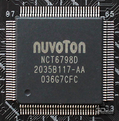
| Контроллер I/O | Nuvoton NCT6798D |
| Форм-фактор, габариты (мм) | ATX, 305 × 244 |
| Поддержка операционной системы | Windows 10 x64 |
| Гарантия производителя, лет | 3 |
| Розничная стоимость, руб. | 21 399 |
⇡#Упаковка и комплектация
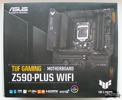
Плата поставляется в картонной коробке стандартных размеров, оформленной в чёрном цвете. На лицевой стороне приведены крупное фото платы ASUS TUF Gaming Z590 Plus WiFi, название модели и пиктограммы с обозначением основных технологий и особенностей платы.
|
|
|
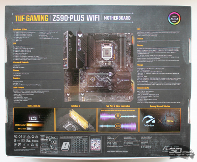
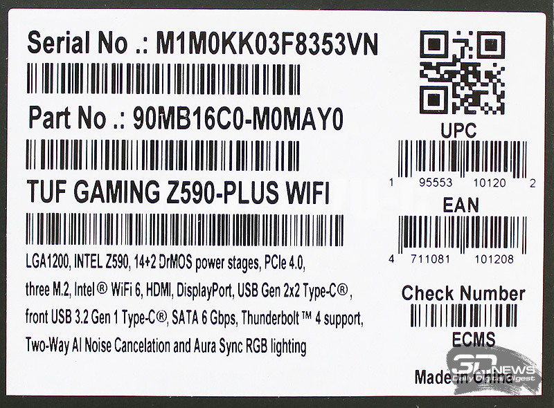
На другой стороне коробки можно ознакомиться с подробными характеристиками TUF Gaming Z590 Plus WiFi и её ключевыми особенностями, а с торца размещён стикер с серийным номером платы и кратким перечислением интерфейсов.
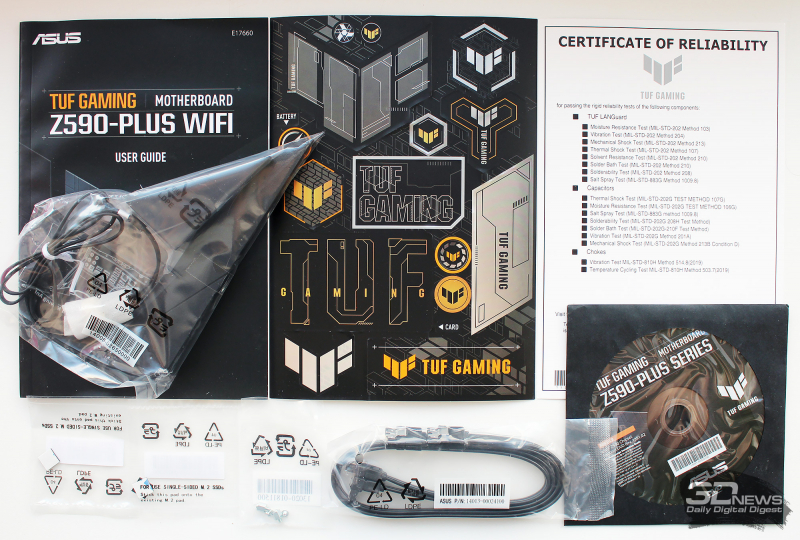
В комплекте с платой поставляются антенна беспроводного модуля связи, винты для крепления накопителей в портах M.2, два кабеля SATA, диск с драйверами и утилитами, инструкция, набор наклеек и сертификат надёжности TUF Gaming.
На выпускаемую в Китае плату предоставляется трёхлетняя гарантия. Розничная стоимость ASUS TUF Gaming Z590 Plus WiFi в России составляет чуть больше 21 тысячи рублей. Как мы и упоминали выше, на сегодняшний день это средний ценовой уровень для плат на наборе системной логики Intel Z590.
⇡#Дизайн и особенности
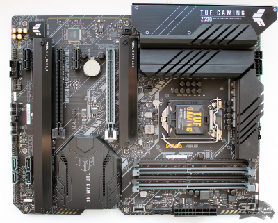
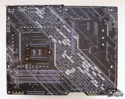
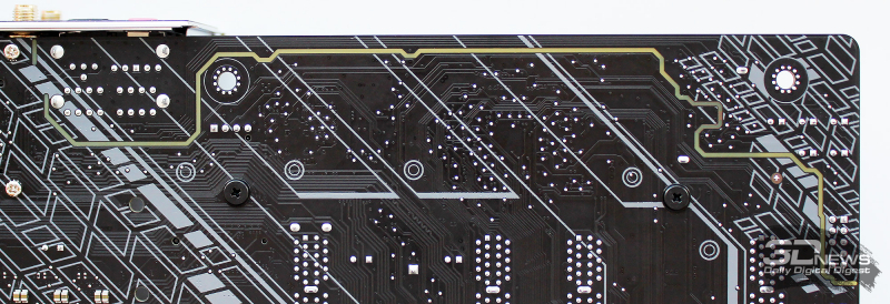
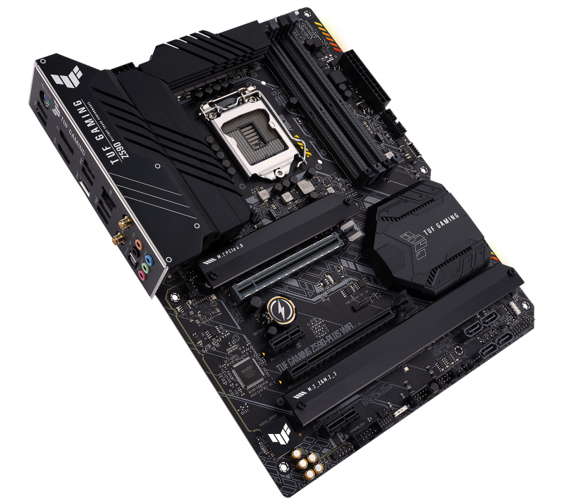
Визуально ASUS TUF Gaming Z590 Plus WiFi — довольно перегруженная плата. К нагромождению радиаторов и разъёмов добавлены косые белые полосы на текстолите, в частности на его обратной стороне, и различная символика серии TUF Gaming.
|
|
|
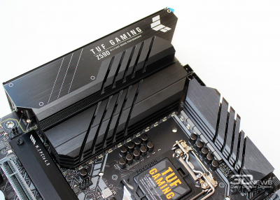
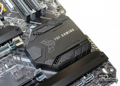
При этом если к радиаторам на цепях VRM нет никаких вопросов — они довольно строгие и правильные с точки зрения охлаждения, — то вот радиатор на чипсете накрыт пластиковым кожухом, который диссонирует с общим дизайном платы и выглядит, прямо говоря, дёшево.
|
|
|
Впрочем, учитывая, что дизайн материнской платы, пожалуй, самый последний пункт, на который стоит обращать внимание при её выборе, не будем записывать его в недостатки ASUS TUF Gaming Z590 Plus WiFi, тем более что вкусы у всех разные. Здесь же добавим, что форм-фактор платы – ATX, размеры – 305 × 244 мм.
Интерфейсная панель содержит почти всё необходимое для работы. Почти — потому как семи портов USB в современных реалиях хватит не всем, и свободное место вполне можно было бы заполнить ещё парой USB 3.2 Gen1.
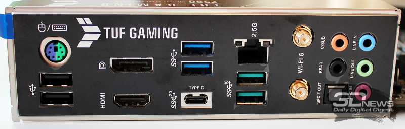
Кроме различного рода портов USB здесь размещены редкий для последнего времени комбинированный PS/2, два видеовыхода HDMI 2.0b и DisplayPort 1.4, 2,5-гигабитная сетевая розетка, коннекторы SMA для антенн беспроводного модуля связи (2T2R) Wi-Fi 6, оптический выход S/PDIF-интерфейса и пять 3,5-мм аудиоразъёмов.
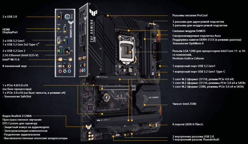
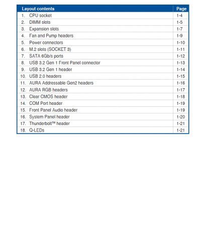
Все ключевые особенности ASUS TUF Gaming Z590 Plus WiFi отмечены на следующей схеме.
Из навесных элементов на текстолите только кожух радиатора чипсета крепится пластиковыми «гвоздиками», а остальные — винтами. Без всего этого плата выглядит следующим образом.
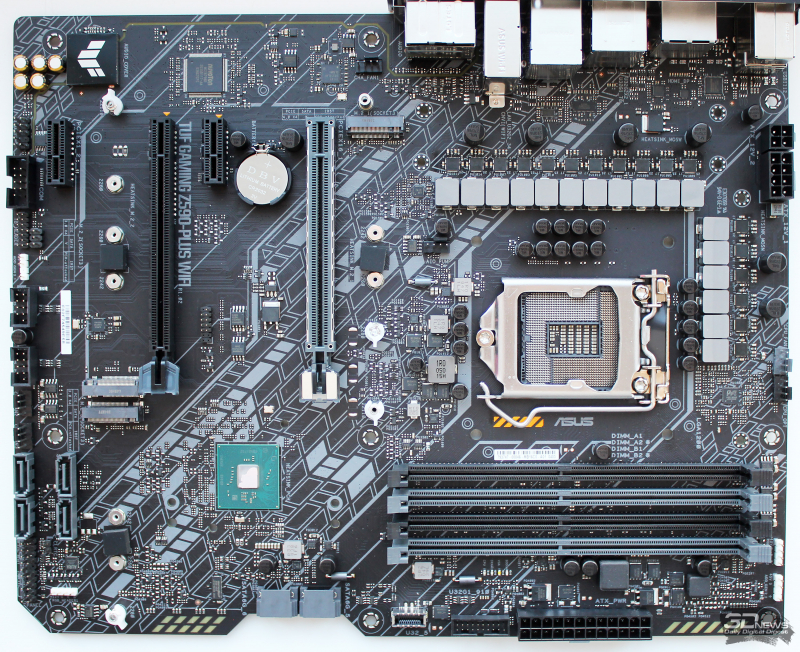
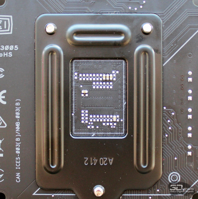
В её основе лежит шестислойный текстолит. Об удвоенной толщине медных слоёв в нём, про которую часто твердят производители в случае других плат, ASUS ничего не говорит.
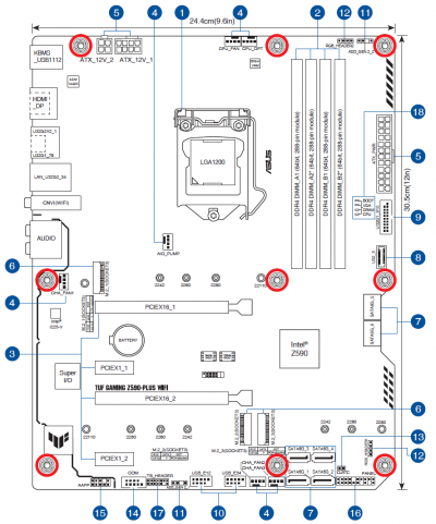
Достаточно подробная инструкция по эксплуатации содержит подробную схему с расположением всех элементов платы, что может помочь при их детальном разборе.
|
|
|
В процессорном разъёме конструктивного исполнения LGA1200 платы ASUS TUF Gaming Z590 Plus WiFi мы не выявили каких-либо особенностей.
|
|
|
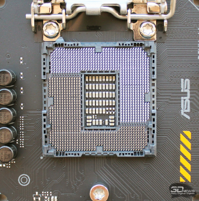
Плата позволяет использовать все процессоры данного конструктивного исполнения, а с полным их перечнем можно ознакомиться на странице поддержки.
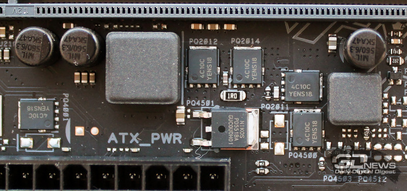
Система питания процессора на ASUS TUF Gaming Z590 Plus WiFi выглядит как шестнадцатифазная, реализованная по схеме «14+2» на силовых модулях DrMOS (50-амперные NCP302150 производства ON Semiconductor).
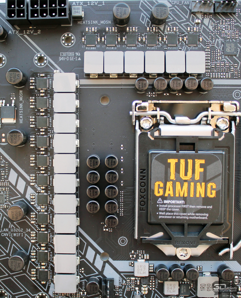
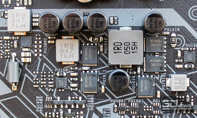
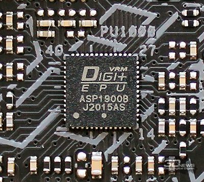
За управление питанием отвечает шим-контроллер Digi+ VRM ASP1900B, то есть на самом деле подсистема питания организована по схеме «7×2+2».
Питанием плата обеспечивается по трём разъёмам: стандартный 24-контактный дополнен восьмиконтактным и четырёхконтактным.
|
|
|
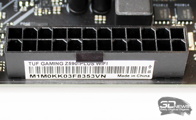
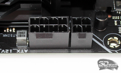
Кстати, разъёмы питания здесь фирменные ProCool, способные выдержать на 25 % более высокую нагрузку, чем стандартные разъёмы, обеспечивающие пониженное электрическое сопротивление и улучшенное теплораспределение. Заявлено применение в них твердотельных игл, но сейчас практически все производители плат перешли на такой формат разъёмов питания.
Система оперативной памяти DDR4 построена по фирменной технологии OptiMem II, когда разные каналы разведены в отдельных слоях текстолита, что исключает вероятность наводок и обеспечивает более стабильную работу памяти на высоких частотах. Сами разъёмы не имеют металлических оболочек, зато оснащены защёлками только с одной стороны. Разъёмы, в которые надо устанавливать память, если вы используете всего две планки, а не четыре, указаны рядом на текстолите.
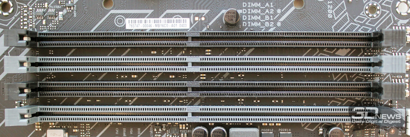
Суммарный объём памяти на плате может достигать 128 Гбайт. Поддержка XMP должна упростить настройку и автоматический подбор частот/таймингов, также на странице поддержки платы приведён перечень сертифицированных модулей с частотами до 4,8 ГГц, хотя официально плата поддерживает модули с частотой до 5,133 ГГц. Добавим здесь, что система питания оперативной памяти одноканальная (как и на всех платах с Intel Z590).
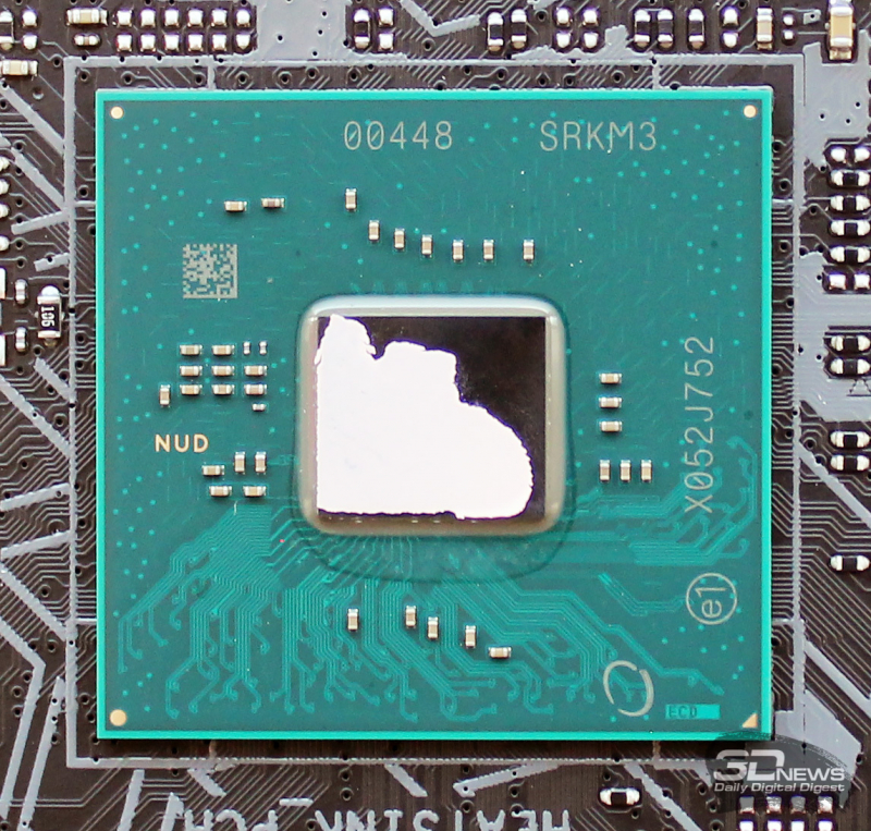
Под единственным пластиковым кожухом на плате скрыт маленький радиатор чипсета. Он настолько простой и лёгкий, что в ASUS не стали закреплять его винтами.
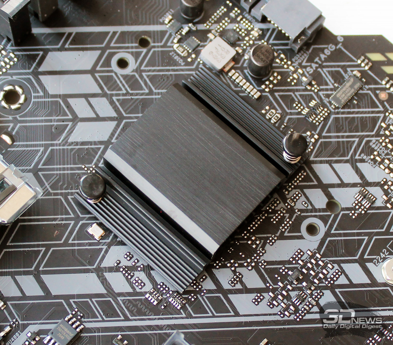
Этот радиатор контактирует с кристаллом набора системной логики Intel Z590 Express через термопрокладку.
ASUS TUF Gaming Z590 Plus WiFi оснащена четырьмя слотами PCI-Express: двумя полноразмерными x16 и двумя короткими х1.
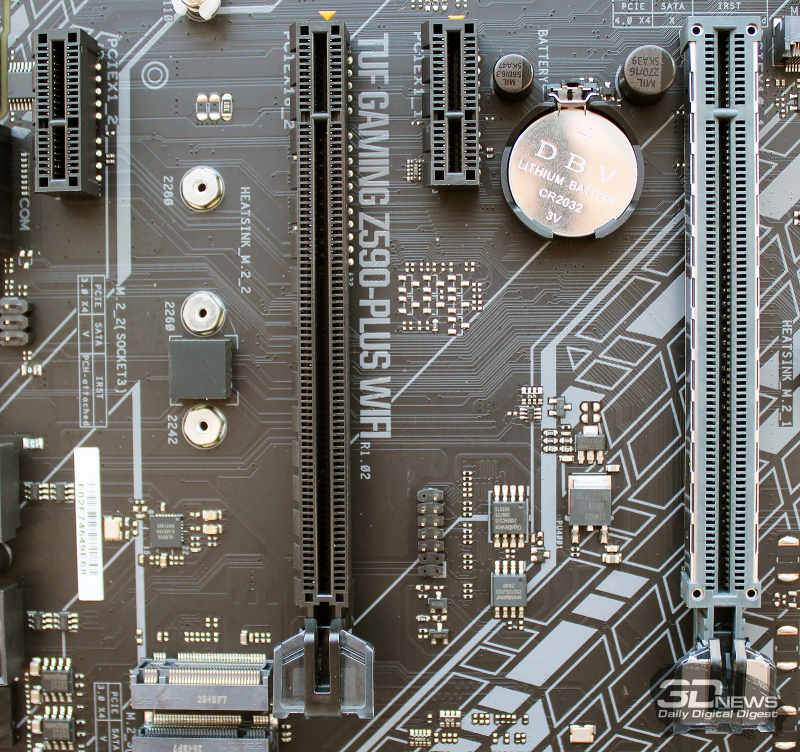
Первый слот облачён в усиливающую и экранирующую алюминиевую оболочку, подключён к процессору и — в зависимости от поколения процессора Intel — может работать в версиях 4.0 или 3.0. Второй полноразмерный слот относится к версии 3.0 и всегда работает в режиме x4, используя чипсетные линии. Ну а с двумя короткими PCI Express 3.0 x1 всё понятно и без комментариев, ресурсы с другими портами и интерфейсами они здесь не делят.
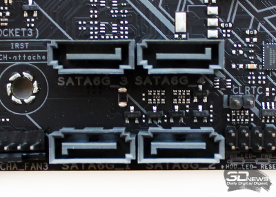
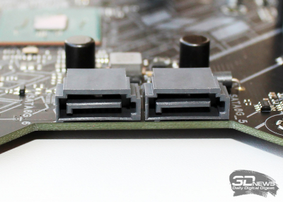
Плата оснащена шестью портами SATA III с пропускной способностью до 6 Гбит/с. Порты с первого по четвёртый расположены вертикально в нижней части платы, а пятый и шестой в горизонтальной ориентации с правого торца.
|
|
|
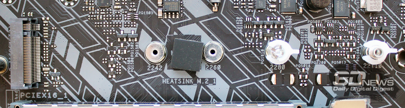
Кроме шести портов SATA, у ASUS TUF Gaming Z590 Plus WiFi для накопителей есть ещё три порта M.2. Верхний подключён к процессору и поддерживает быстрые накопители стандарта PCIe 4.0 длиной от 42 до 110 мм.
Данный слот будет отключён при установке в плату процессора Intel 10-го поколения.
Работу двух нижних слотов обеспечивает чипсет Intel Z590, и в них могут устанавливаться накопители SATA- и PCI Express-типа длиной от 42 до 110 мм (M2_2) и от 42 до 80 мм (M2_3).
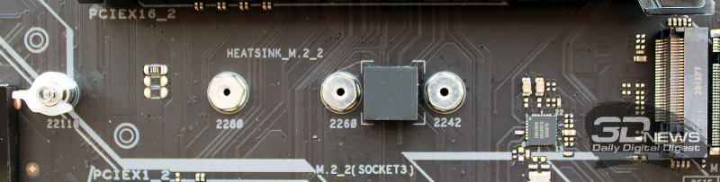
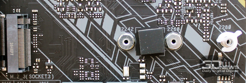
При установке во второй слот накопителя SATA-типа будет отключён второй порт SATA, а при установке в третий слот такого же накопителя недоступными станут пятый и шестой порты SATA. Отметим, что все порты M.2 оснащены радиаторами с термопрокладками Laird с заявленной теплопроводностью 7 Вт/(м·К) и фирменными фиксаторами ASUS Q-Latch, не требующими использования винтов. Кстати, это оказалось очень удобно.
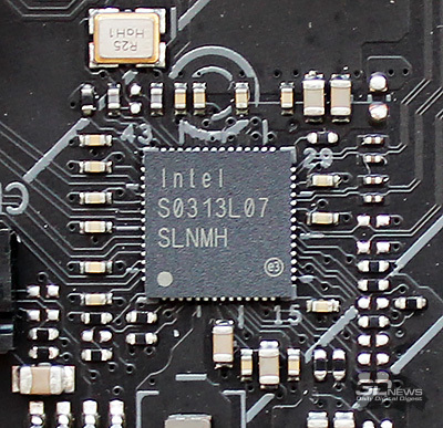
Проводной сетевой контроллер на плате реализован микропроцессором Intel I225-V вкупе с фирменной технологией приоритизации трафика ASUS TurboLAN.
За беспроводные соединения здесь отвечает модуль Intel Wi-Fi 6 AX201 с поддержкой Wi-Fi 6 и Bluetooth 5.2.
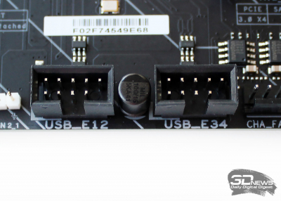
ASUS TUF Gaming Z590 Plus WiFi оснащена 14 портами USB, которые поделены поровну между интерфейсной панелью и разъёмами на печатной плате. Среди них выделим один быстрый порт Type-C USB 3.2 Gen2 с пропускной способностью до 20 Гбит/с и один порт USB 3.2 Gen2 (до 10 Гбит/с) для передней панели корпуса системного блока.
|
|
|
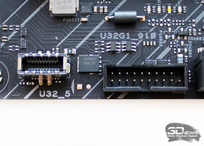
Выделенного интерфейса Thunderbolt на плате нет (только коннектор для него), но порт USB 3.2 Gen2 Type-C пригоден для подключения контроллера ASUS ThunderboltEX 4.
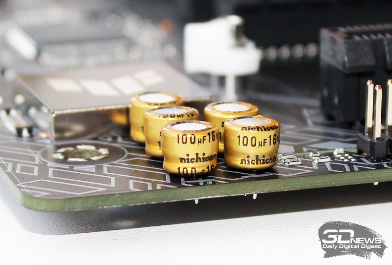
Звук на плате реализован 7.1-канальным HD-аудиокодеком Realtek S1200A, который защищён алюминиевым колпачком.
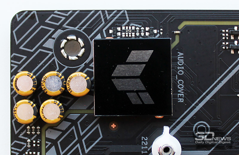
Рядом с ним распаяны пять аудиоконденсаторов nichicon японского производства.
Никаких дополнительных микросхем (усилителя или ЦАП) в аудиотракте платы мы не обнаружили, а из аппаратных улучшений здесь есть только разведение левого и правого каналов в разных слоях текстолита и изоляция зоны аудиокомпонентов от остальной части печатной платы токонепроводящей полоской.
Заявленное в спецификациях соотношение «сигнал — шум» составляет 108 дБ для линейного стереовыхода и 103 дБ для линейного входа, а на программном уровне поддерживается технология DTS Custom.
За обеспечение функций Multi I/O и мониторинга на ASUS TUF Gaming Z590 Plus WiFi отвечает микроконтроллер Nuvoton NCT6798D.
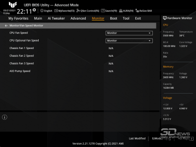
Плата может управлять шестью вентиляторами, два из которых процессорные, три корпусные, а последний разъём предназначен для помпы системы жидкостного охлаждения, хотя вентилятор к нему подключить, конечно же, тоже можно.
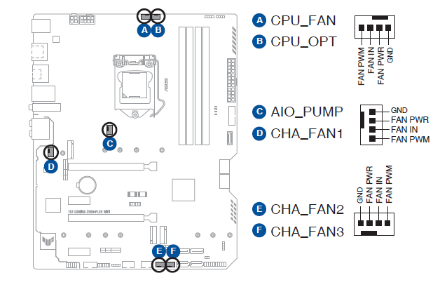
При этом все разъёмы имеют силу тока 1 А и мощность 12 Вт. Разъёмов повышенной мощности на данной плате нет. Правда, вряд ли это можно назвать минусом, так как, к примеру, мощный вентилятор Noctua NF-F12 industrialPPC-3000 PWM на скорости 3000 об/мин потребляет всего 3,6 Вт.
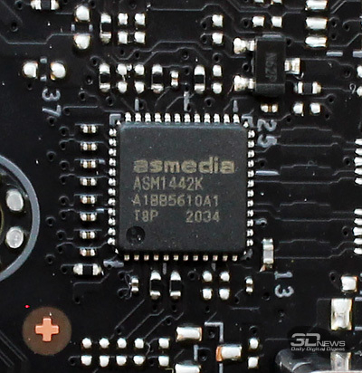
Также в контексте описания контроллеров платы отметим, что за вывод видеосигнала через порт HDMI в формате 4K на плате отвечает небольшая микросхема ASMedia ASM1442K.
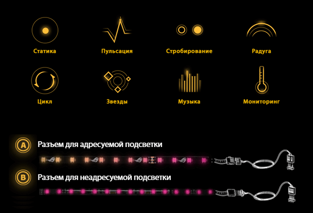
На печатной плате есть две миниатюрных зоны подсветки: рядом с чипсетом и рядом с 24-контактным разъёмом питания. Для подключения светодиодных лент предусмотрены четыре разъёма RGB: два с адресацией и два без неё.
|
|
|
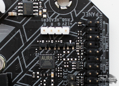
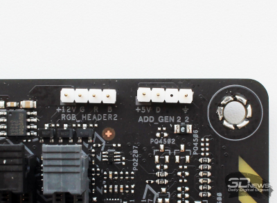
Управление подсветкой реализовано в приложении ASUS Aura с возможностью выбора эффектов и цвета.
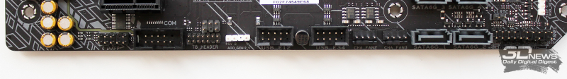
Нижний край текстолита содержит коннекторы COM-порта и Thunderbolt, два разъёма USB 2.0 и два разъёма для вентиляторов, SATA-разъёмы, а также коннекторы для кабелей передней панели корпуса.
На плате, к сожалению, нет индикатора POST-кодов, но есть хотя бы четыре светодиода CPU/DRAM/VGA/BOOT, сигнализирующие о возможных проблемах при прохождении процедуры POST (Power On Self Test).
В системе охлаждения ASUS TUF Gaming Z590 Plus WiFi нет тепловых трубок, однако основной радиатор на цепи VRM имеет увеличенную в 1,6 раза площадь (видимо, в сравнении с предыдущей версией TUF на Z490) и по форме плавно переходит в кожух панели ввода-вывода.
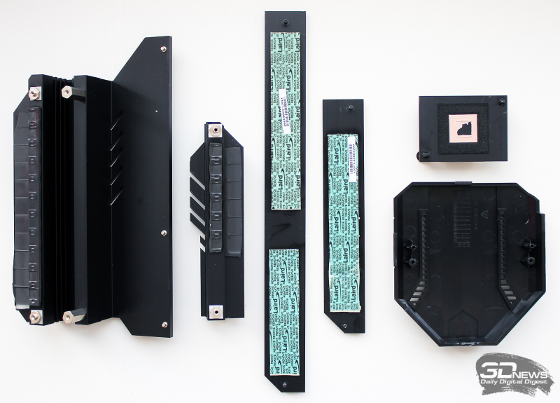
Также интересно выглядит единая пластина-радиатор на два нижних порта M.2. Про эффективные термопрокладки Laird на ней мы уже писали выше. Не вызывает доверия только уж очень маленький радиатор на чипсете, но, как показали дальнейшие тесты, со своей задачей он вполне справляется.
⇡#Возможности UEFI BIOS
ASUS TUF Gaming Z590 Plus WiFi оснащена одной микросхемой BIOS, и у нас в неё была прошита последняя доступная на момент подготовки статьи версия 0820 от 28 апреля 2021 года. Оформление оболочки продолжает линию дизайна платы и её коробки. Стартует BIOS в упрощённом режиме EzMode, который в большей степени является информационным.
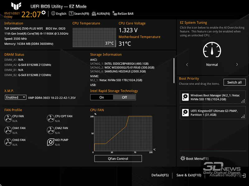
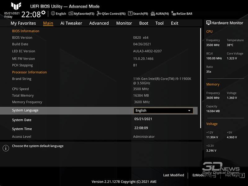
Переключиться в расширенный режим настроек можно через функциональную клавишу F7. Здесь откроются привычные семь основных разделов и «Избранное». В первом разделе, Main, можно узнать версию BIOS платы, модель установленного процессора, а также объём и частоту оперативной памяти. Здесь же выбирается язык оболочки, доступен, в частности, и русский.
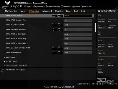
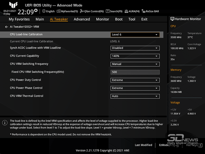
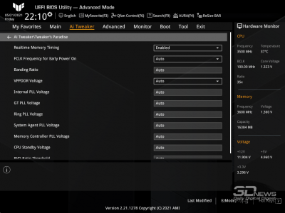
Далее идёт основной раздел Ai Tweaker, где собраны все настройки центрального процессора, оперативной памяти и их разгона.
|
|
|
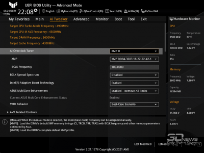
За исключением нескольких уникальных для Roсket Lake-S параметров, он не отличается от аналогичных разделов на других материнских платах ASUS и предоставляет пользователю практически безграничные возможности неэкстремального оверклокинга.
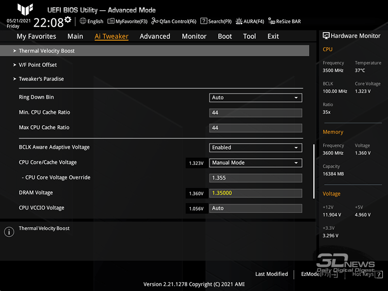
Набор доступных для изменения напряжений в BIOS ASUS TUF Gaming Z590 Plus WiFi не назовёшь рекордным, однако всё необходимое в него включено.
| Напряжение | Минимальное значение, В | Максимальное значение, В | Шаг |
| CPU Core | 0,600 | 1,700 | 0,005 |
| CPU SA | 0,700 | 1,800 | 0,010 |
| CPU VCCIO | 0,700 | 1,800 | 0,010 |
| VCCIO Mem OC | 0,700 | 1,600 | 0,010 |
| DRAM | 1,000 | 1,800 | 0,010 |
| PCH VCCIN | 1,800 | 2,300 | 0,010 |
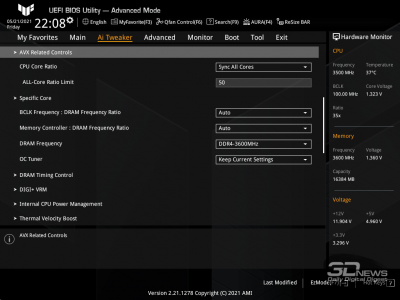
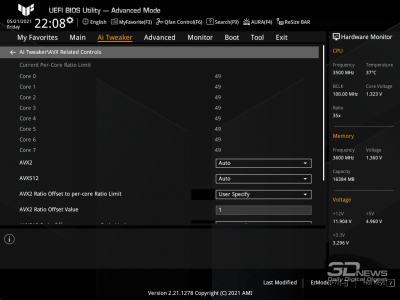
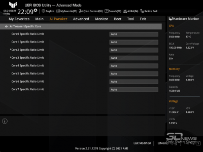
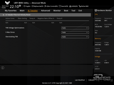
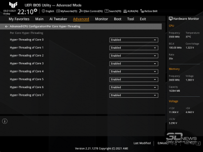
В отдельных вкладках этого основного раздела можно настроить лимиты множителей для каждого ядра процессора отдельно.
|
|
|
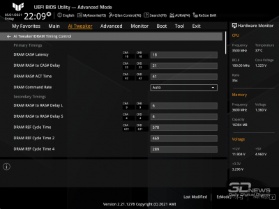
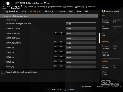
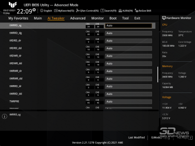
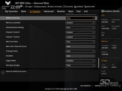
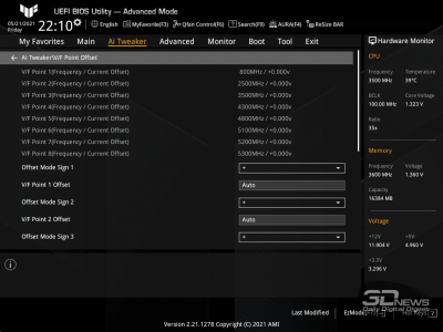
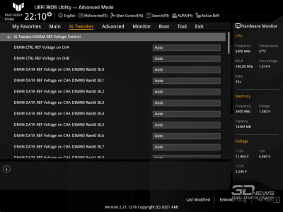
Частоту оперативной памяти в BIOS можно выставить на уровне 8 ГГц, а тайминги и связанные с ними сопутствующие настройки вообще устанешь листать.
|
|
|
|
|
|
|
|
|

Уровней стабилизации напряжения на ядре процессора (LLC) восемь, где минимальный – единица, а самый агрессивный – восьмёрка.
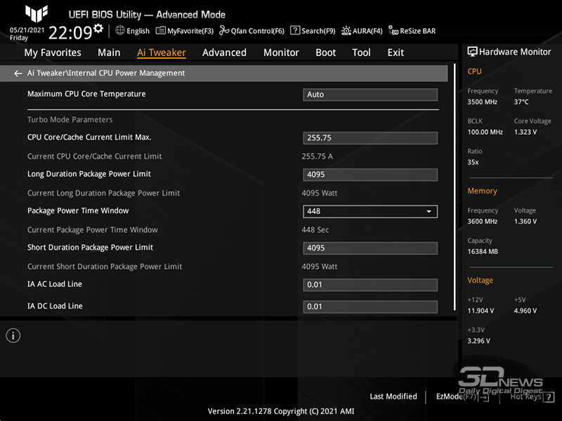
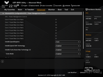
Важный подраздел BIOS называется Internal CPU Power Management. Здесь можно отрегулировать лимиты питания процессора и длительность их превышения до срабатывания «отсечки» в виде троттлинга, а также прочие параметры.
|
|
|
|
|
|
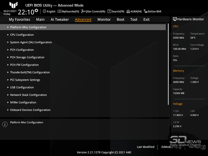
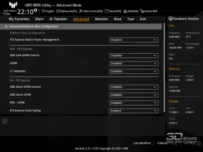
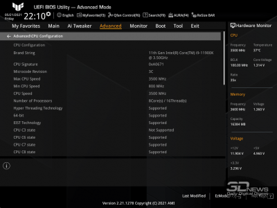
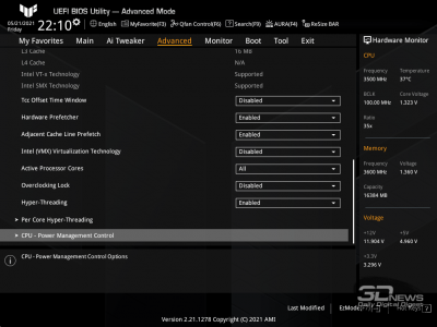
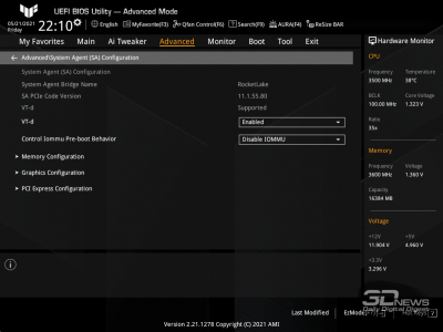
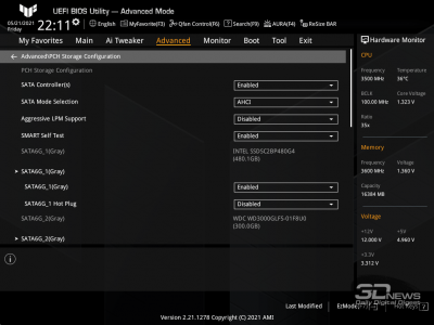
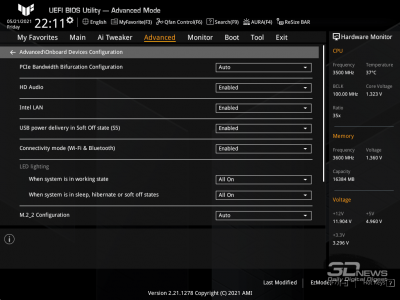
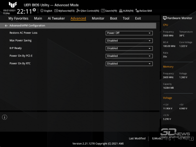
В основном разделе Advanced размещены настройки контроллеров платы и различных периферийных устройств.
|
|
|
|
|
|
|
|
|
|
|
|
|
|
|
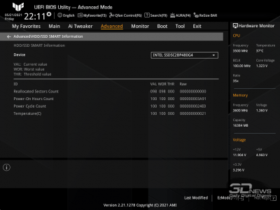
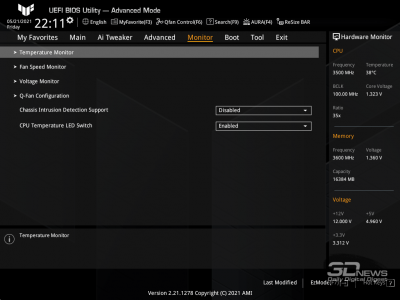
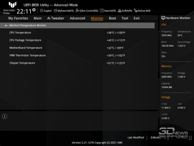
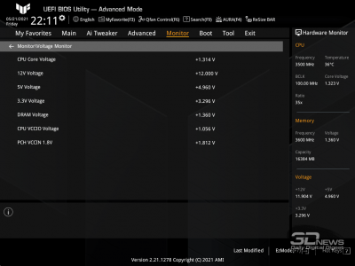
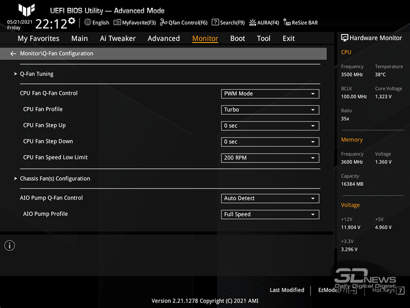
В разделе с мониторингом можно контролировать температуры и напряжения компонентов, скорости вентиляторов, а также настроить скорость их вращения в автоматическом или ручном режиме.
|
|
|
|
|
|
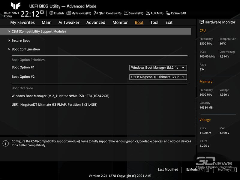
С загрузкой всё обычно: можно было даже не отводить на неё целый основной раздел, а, например, объединить с Exit.
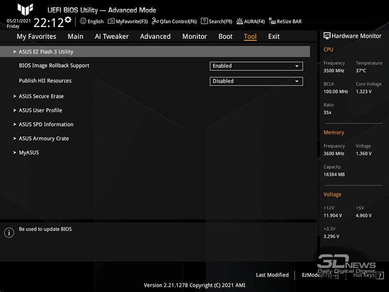
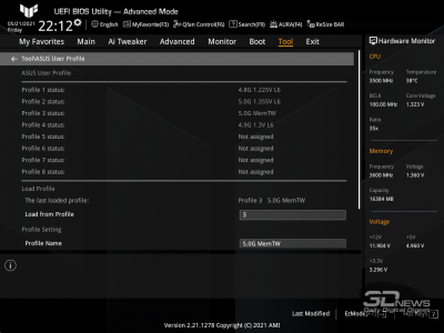
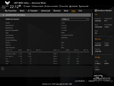
Из встроенных утилит в BIOS есть обновление микрокода, безопасная очистка накопителей, создание и загрузка профилей настроек BIOS (8 слотов).
Там же есть вкладки с подробнейшей информацией о центральном процессоре и оперативной памяти.
|
|
|
При выходе из BIOS отображается окно с внесёнными в него в процессе юстировки изменениями, что позволяет проверить, правильно ли откорректированы все параметры.
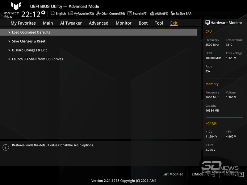
Добавим, что каких-либо проблем при работе в BIOS мы не выявили. Со скоростью работы оболочки у ASUS TUF Gaming Z590 Plus WiFi также всё в полном порядке.
⇡#Разгон и стабильность
Проверка стабильности, оверклокерского потенциала и производительности материнской платы ASUS TUF Gaming Z590 Plus WiFi была проведена в закрытом корпусе системного блока при температуре в помещении от 26,5 до 26,8 градуса Цельсия. Конфигурация тестового стенда состояла из следующих комплектующих:
- системная плата: ASUS TUF Gaming Z590 Plus WiFi (Intel Z590, LGA1200, BIOS 0820 от 28.04.2021);
- процессор: Intel Core i9-11900K 3,5-5,3 ГГц (Rocket Lake-S, 14++ нм, B0, 8 × 512 Kбайт L2, 16 Мбайт L3, TDP 125 Вт);
- система охлаждения CPU: Noctua NH-D15S chromax.black (два 140-мм вентилятора Noctua NF-A15 на 830–1480 об/мин);
- термоинтерфейс: ARCTIC MX-4;
- видеокарта: NVIDIA GeForce RTX 2080 SUPER Founders Edition 8 Гбайт/256 бит, с разгоном до 1770-1935(2050)/18304 МГц;
- оперативная память: DDR4 2 × 8 Гбайт G.Skill TridentZ Neo (F4-3600C18Q-32GTZN), XMP 3600 МГц 18-22-22-42 CR2 при 1,35 В;
- накопители:
- для системы: Netac NVMe SSD 1 Тбайт (NT01N950E-001T-E4X);
- для бенчмарков: Intel SSD 730 480 Гбайт (SATA III, BIOS vL2010400);
- для программ и игр: Western Digital VelociRaptor 300 Гбайт (SATA II, 10000 об/мин, 16 Мбайт, NCQ);
- архивный: Samsung Ecogreen F4 HD204UI 2 Тбайт (SATA II, 5400 об/мин, 32 Мбайт, NCQ);
- корпус: Thermaltake Core X71 (шесть 140-мм be quiet! Silent Wings 3 PWM [BL067], 990 об/мин, три – на вдув, три – на выдув);
- панель управления и мониторинга: Zalman ZM-MFC3;
- блок питания: Corsair AX1500i Digital ATX (1,5 кВт, 80 Plus Titanium), 140-мм вентилятор.
Тестирование было проведено под управлением операционной системы Microsoft Windows 10 Pro версии 20H2 (19042.985) с установкой следующих драйверов:
- чипсет материнской платы Intel Chipset Drivers – 10.1.18716.8265 WHQL от 01.04.2021;
- Intel Management Engine Interface (MEI) – 2110.15.0.2210 WHQL от 25.03.2021;
- драйверы видеокарты – NVIDIA GeForce 465.89 WHQL от 30.03.2021.
Стабильность системы при разгоне мы проверяли стресс-утилитой Prime95 30.5 build 2 (без AVX-инструкций) и другими бенчмарками, а мониторинг проводился с помощью HWiNFO64 версии 7.03-4450.
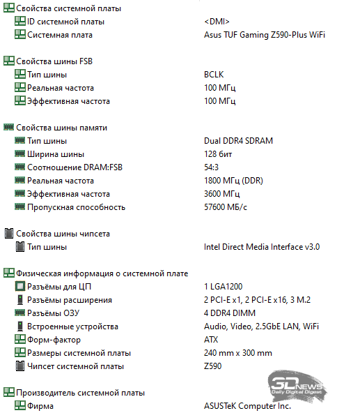
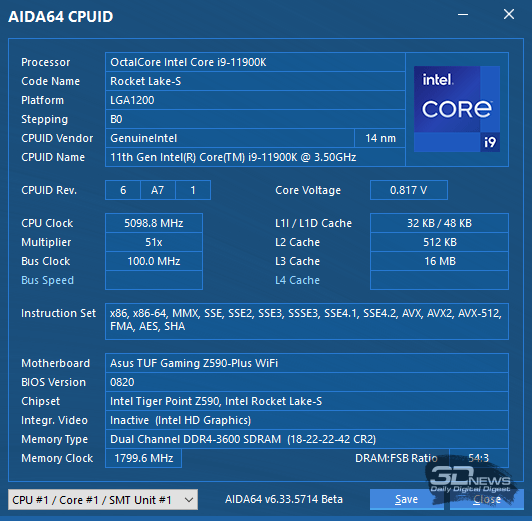
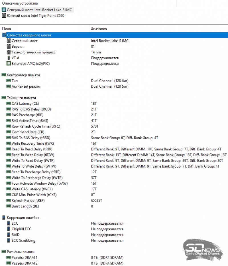
Сначала приведём основные характеристики платы из утилиты AIDA64 Extreme.
Большинство пользователей используют платы, не внося изменения в настройки BIOS, поэтому первый тест мы традиционно проводим с настройками по умолчанию, ограничившись только активацией XMP оперативной памяти. ASUS TUF Gaming Z590 Plus WiFi не стала исключением, уверенно и быстро стартовав, мигая подсветкой.
По одному ядру процессор поднимал частоту до 5,3 ГГц, а несколько сразу кратковременно могли работать на 5,1 ГГц, однако при одновременной высокой нагрузке на все восемь ядер частота строго держалась на уровне 4,7 ГГц.
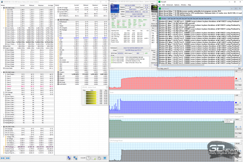
При этом суперкулер вполне справлялся с такой нагрузкой, не позволяя температуре наиболее горячего ядра превысить отметку 80 градусов Цельсия, а плата обеспечивала очень эффективное охлаждение VRM-цепей (всего 53 градуса Цельсия в пике нагрузки). Иначе говоря, простор для активации технологии Adaptive Boost в BIOS платы, когда все ядра должны были работать на 5,1 ГГц, оставался. Активировав эту настройку и отодвинув все лимиты питания на максимум, мы прогнали стресс-тест повторно, получив следующую картину.
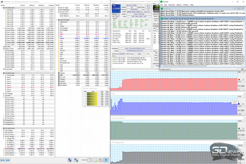
Не изменилось практически ничего, не считая двухградусного снижения пиковой температуры CPU. Процессор так и работал на 4,7 ГГц по всем ядрам, ни о каких 5,1 ГГц не было и речи. Многочисленные и разнообразные попытки активировать Adaptive Boost одновременно с другими параметрами BIOS закончились безрезультатно, поэтому мы перешли к изучению потенциала процессора и платы при ручном разгоне.
За несколько часов тестирования удалось выяснить, что для стабильности процессора на частоте 4,8 ГГц одновременно по всем ядрам на плате ASUS TUF Gaming Z590 Plus WiFi требуется напряжение 1,225 В (187 ватт), а на 4,9 ГГц – 1,290 В (220 ватт). Покорилась нашему экземпляру и отметка 5,0 ГГц по всем ядрам одновременно. Для этого потребовалось поднять напряжение до 1,355 В.

Суперкулер всё ещё справлялся с такой нагрузкой, хотя температура достигла 95 градусов Цельсия, а энергопотребление превысило отметку 253 ватта.
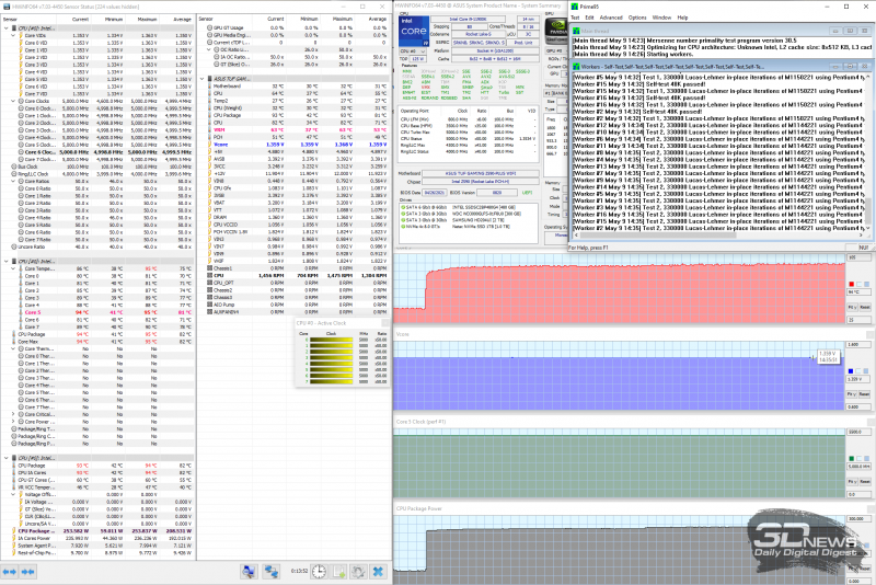
Разогнать выше процессор уже не удавалось, но это проблема вовсе не платы ASUS TUF Gaming Z590 Plus WiFi, VRM которой выше 63 градусов Цельсия так и не прогрелся, а конкретного экземпляра процессора Intel Core i9-11900K.
Оперативная память G.Skill TridentZ Neo на этой плате смогла стабильно работать на 3,8 ГГц, но мы выбрали вариант 3,6 ГГц с заниженными таймингами, который позволял достичь более высокой производительности.
⇡#Производительность
Поскольку ранее мы тестировали с таким же процессором плату MSI MEG Z590 Ace при активированной технологии Adaptive Boost, то в сегодняшней статье решили сравнить производительность того же самого экземпляра процессора Intel Core i9-11900K на ASUS TUF Gaming Z590 Plus WiFi, но при фиксированной на 5,0 ГГц частоте ядер. Будет ли разница — и если да, то где именно и в какую сторону? Результаты в таблице.
| Наименование теста | Показатель | ASUS TUF Gaming Z590 Plus WiFi + Intel Core i9-11900K 5,0 ГГц (фикс.) |
MSI MEG Z590 Ace + Intel Core i9-11900K 3,5-5,3 ГГц (авто) |
% отклонения | |
| AIDA64 memtest | Чтение | ↑ | 55 441 | 55 313 | 0,2% |
| Запись | ↑ | 54 823 | 54 431 | 0,7% | |
| Копирование | ↑ | 54 363 | 54 234 | 0,2% | |
| Latency | ↓ | 47,8 | 46,1 | -3,7% | |
| WinRAR | KB/s | ↑ | 28 000 | 28 890 | -3,1% |
| 7-Zip | MIPS | ↑ | 94 127 | 96 672 | -2,6% |
| HandBrake | H.265 MKV 4K, s | ↓ | 234,20 | 243,90 | 4,0% |
| CineBench R23 | CPU (Multi Core), pts | ↑ | 16 306 | 16 499 | -1,2% |
| CPU (Single Core), pts | ↑ | 1 603 | 1 695 | -5,4% | |
| Blender (Classroom) | Classroom, time | ↓ | 0:06:47 | 0:07:45 | 12,5% |
| FLAC to MP3 | Speed | ↑ | 300,22 | 260,90 | 15,1% |
| Geekbench 5 | Single-Core Score | ↑ | 1 810 | 1 873 | -3,4% |
| Multi-Core Score | ↑ | 11 507 | 11 715 | -1,8% | |
| VeraCrypt (Kuznyechik (Serpent (Camellia) |
Encryption, MiB/s | ↑ | 1 100 | 1 100 | 0,0% |
| Decryption, MiB/s | ↑ | 1 000 | 1 000 | 0,0% | |
| Solidworks 2021 | Graphics, s | ↓ | 24,4 | 23,6 | -3,4% |
| Processor | ↓ | 17,6 | 17,5 | -0,6% | |
| I/O | ↓ | 15,1 | 14,4 | -4,9% | |
| PCMark’10 | Total | ↑ | 8 159 | 8 020 | 1,7% |
| Essentials | ↑ | 11 707 | 11 485 | 1,9% | |
| Productivity | ↑ | 11 756 | 11 467 | 2,5% | |
| Digital Content Creation | ↑ | 10 710 | 10 630 | 0,8% | |
| 3DMark Time Spy | CPU score | ↑ | 13 829 | 12 811 | 7,9% |
| World of Tanks enCore RT (среднее качество) | Score | ↑ | 107 914 | 105 264 | 2,5% |
ASUS TUF Gaming Z590 Plus WiFi с процессором при фиксированной на 5,0 ГГц частоте продемонстрировала преимущество перед MSI MEG Z590 Ace с автобустом процессора в многопоточных тестах HandBrake, Blender, перекодировании аудиофайлов и 3DMark Time Spy. Во всех остальных бенчмарках разница между этими платами и настройками работы процессора не существенная. Так что даже если с Adaptive Boost плата по каким-то причинам не совладает, то от Intel Rocket Lake-S всегда можно добиться практически того же самого на фиксированной частоте процессора, а в многопоточных тестах — ещё и получить преимущество.
⇡#Заключение
На наш взгляд, ASUS TUF Gaming Z590 Plus WiFi можно назвать эталонной платой среднего класса для процессоров с LGA1200. Вы уже справедливо возмущаетесь, ведь цена у неё далеко не средняя, но современные реалии рынка Hi-Tech, увы, именно таковы, что за 20 тысяч рублей на флагманском чипсете сегодня можно купить только плату с базовым набором возможностей — и не более того. При этом из того, чего в ней реально не хватает, выделим только индикатор POST-кодов и, пожалуй, резервную микросхему BIOS. Все остальные присущие геймерской модели платы особенности у TUF Gaming Z590 Plus WiFi имеются и стабильно работают.
Здесь есть мощная система питания с 50-амперными фазами, есть поддержка оперативной памяти с частотой до 5,133 ГГц, есть три M.2, шесть SATA и 14 USB, 2,5-гигабитная проводная сеть и Wi-Fi 6-адаптер (есть версия платы без него), а также базовый звуковой кодек. Немаловажно, что плата оснащена эффективными радиаторами на цепях VRM, может одновременно управлять шестью вентиляторами и мониторить пять встроенных температурных сенсоров. Наконец, есть встроенная подсветка и четыре дополнительных коннектора для светодиодных лент или синхронизации подсветки с другими комплектующими.
В сухом остатке ASUS TUF Gaming Z590 Plus WiFi – достойный, хотя и без излишеств, вариант современной платы для Roсket Lake-S на наборе системной логики Intel Z590.
Если Вы заметили ошибку — выделите ее мышью и нажмите CTRL+ENTER.
- Manuals
- Brands
- Asus Manuals
- Motherboard
- TUF Z390-PLUS GAMING
- User manual
-
Contents
-
Table of Contents
-
Bookmarks
Quick Links
Related Manuals for Asus TUF Z390-PLUS GAMING
Summary of Contents for Asus TUF Z390-PLUS GAMING
-
Page 1
TUF Z390-PLUS GAMING… -
Page 2
Product warranty or service will not be extended if: (1) the product is repaired, modified or altered, unless such repair, modification of alteration is authorized in writing by ASUS; or (2) the serial number of the product is defaced or missing. -
Page 3: Table Of Contents
Contents Safety information …………………. vi About this guide ………………….vii TUF Z390-PLUS GAMING specifications summary ……….ix Package contents ………………… xiii Installation tools and components …………….. xiv Chapter 1: Product Introduction Motherboard overview …………….1-1 1.1.1 Before you proceed …………..1-1 1.1.2…
-
Page 4
3.6.13 HDD/SSD SMART Information ……….3-22 Monitor menu ………………. 3-22 Boot menu ………………..3-23 Tool menu ………………..3-24 3.9.1 ASUS EZ Flash 3 Utility …………3-24 3.9.2 ASUS User profile …………..3-24 3.9.3 ASUS SPD Information …………. 3-25 3.9.4 ASUS Q-Installer …………… 3-25 3.10… -
Page 5
RAID configurations ……………… 4-1 4.1.1 RAID definitions …………….4-1 Appendix Notices ……………………A-1 ASUS contact information ………………A-5… -
Page 6: Safety Information
Safety information Electrical safety • To prevent electrical shock hazard, disconnect the power cable from the electrical outlet before relocating the system. • When adding or removing devices to or from the system, ensure that the power cables for the devices are unplugged before the signal cables are connected. If possible, disconnect all power cables from the existing system before you add a device.
-
Page 7: About This Guide
Refer to the following sources for additional information and for product and software updates. ASUS website The ASUS website (www.asus.com) provides updated information on ASUS hardware and software products. Optional documentation Your product package may include optional documentation, such as warranty flyers, that may have been added by your dealer.
-
Page 8
Conventions used in this guide To ensure that you perform certain tasks properly, take note of the following symbols used throughout this manual. DANGER/WARNING: Information to prevent injury to yourself when trying to complete a task. CAUTION: Information to prevent damage to the components when trying to complete a task. -
Page 9: Tuf Z390-Plus Gaming Specifications Summary
TUF Z390-PLUS GAMING specifications summary Intel Socket 1151 for Intel Core™ 9000 series, 8 Generation Intel Core™ ® ® ® i7 / i5 / i3, Pentium and Celeron processors ® ® Supports 14nm CPU Supports Intel Turbo Boost Technology 2.0* ®…
-
Page 10
— ASUS SafeSlot: Protect your graphics card Investment — ASUS ESD Guard: Enhanced ESD protection — ASUS Overvoltage Protection: World-class circuit-protecting power design — ASUS Stainless-Steel Back I/O: 3X corrosion-resistance for greater durability! — ASUS DIGI+ VRM: 8+1 Phase digital power design… -
Page 11
TUF Z390-PLUS GAMING specifications summary OptiMem II — Higher performance of memory overclocking. Enhance compatibility for some memory with RGB. MemOK! II — Enhance memory compatibility. More smart and convenient. Keep high performance. (Shorten the PC starting time) Q-Installer — Auto download driver and software. Friendly for first PC builder. -
Page 12
Anti-virus software (OEM version) Windows 10 64-bit ® Operating system support ATX form factor: 12.0 in. x 9.6 in. (30.5 cm x 24.4cm) Form factor Specifications are subject to change without notice. Please refer to the ASUS website for the latest specifications. -
Page 13: Package Contents
Package contents Check your motherboard package for the following items. Motherboard TUF Z390-PLUS GAMING Cables 2 x SATA 6Gb/s cables 1 x IO Shield Accessories 1 x M.2 Screw Package (2-in-1) 1 x TUF GAMING Sticker Application drive Motherboard support DVD…
-
Page 14: Installation Tools And Components
Installation tools and components Intel 1151 CPU ® Intel 1151 compatible CPU Fan ® Phillips (cross) screwdriver SATA hard disk drive PC chassis 1 bag of screws DIMM Power supply unit SATA optical disc drive (optional) Graphics card The tools and components listed above are not included in the motherboard package.
-
Page 15: Chapter 1: Product Introduction
Chapter 1: Product Introduction Product Introduction Motherboard overview 1.1.1 Before you proceed Take note of the following precautions before you install motherboard components or change any motherboard settings. • Unplug the power cord from the wall socket before touching any component. • Before handling components, use a grounded wrist strap or touch a safely grounded object or a metal object, such as the power supply case, to avoid damaging them due to static electricity. • Hold components by the edges to avoid touching the ICs on them. • Whenever you uninstall any component, place it on a grounded antistatic pad or in the bag that came with the component. • Before you install or remove any component, ensure that the ATX power supply is switched off or the power cord is detached from the power supply. Failure to do so may cause severe damage to the motherboard, peripherals, or components. TUF Z390-PLUS GAMING…
-
Page 16: Motherboard Layout
1.1.2 Motherboard layout 24.4cm(9.6in) KBMS EATX12V CPU_FAN DIGI+ CPU_OPT U31G2_12 Mem_LED MemOK!_II U31G1_34 HDMI LGA1151 LAN_U31G1_56 AIO_PUMP AUDIO CHA_FAN1 PCIEX1_1 2280 2260 2242 PCIE SATA IRST M.2_1(SOCKET3) PCIEX16_1 219V ® Intel ® Z390 PCIEX1_2 Super BATTERY 128Mb BIOS PCIEX16_2 ASM1480 PCIEX1_3 22110 2280…
-
Page 17: Central Processing Unit (Cpu)
10. Clear RTC RAM jumper (2-pin CLRTC) 11. AURA RGB headers (4-pin RGB_HEADER1/2) 12. System panel connector (20-5 pin PANEL) 1-15 13. USB 2.0 connector (10-1 pin USB1112, USB1314) 1-12 14. Digital audio connector (4-1 pin SPDIF_OUT) 1-16 15. Front panel audio connector (10-1 pin AAFP) 1-13 1.1.3 Central Processing Unit (CPU) The motherboard comes with an Intel Socket 1151 for Intel Core™ 9000 series, 8 ® ® Generation Core™ i7 / i5 / i3, Pentium and Celeron processors. ® ® ® TUF Z390-PLUS GAMING CPU LGA1151 TUF Z390-PLUS GAMING…
-
Page 18: System Memory
• Ensure that you install the correct CPU designed for LGA1151 socket only. DO NOT install a CPU designed for LGA1150, LGA1155, and LGA1156 sockets in the LGA1151 socket. • Ensure that all power cables are unplugged before installing the CPU. • Upon purchase of the motherboard, ensure that the PnP cap is on the socket and the socket contacts are not bent. Contact your retailer immediately if the PnP cap is missing, or if you see any damage to the PnP cap/socket contacts/motherboard components. • Keep the cap after installing the motherboard. ASUS will process Return Merchandise Authorization (RMA) requests only if the motherboard comes with the cap on the LGA1151 socket. • The product warranty does not cover damage to the socket contacts resulting from incorrect CPU installation/removal, or misplacement/loss/incorrect removal of the PnP cap. 1.1.4 System memory The motherboard comes with four DDR4 (Double Data Rate 4) Dual Inline Memory Modules (DIMM) slots. A DDR4 module is notched differently from a DDR, DDR2, or DDR3 module. DO NOT install a DDR, DDR2, or DDR3 memory module to the DDR4 slot. ® TUF Z390-PLUS GAMING 288-pin DDR4 DIMM sockets Chapter 1: Product Introduction…
-
Page 19
Recommended memory configurations Memory configurations You may install 2 GB, 4 GB, 8 GB and 16 GB unbuffered and non-ECC DDR4 DIMMs into the DIMM sockets. You may install varying memory sizes in Channel A, and Channel B. The system maps the total size of the lower-sized channel for the dual-channel configuration. Any excess memory from the higher-sized channel is then mapped for single-channel operation. • The default memory operation frequency is dependent on its Serial Presence Detect (SPD), which is the standard way of accessing information from a memory module. Under the default state, some memory modules for overclocking may operate at a lower frequency than the vendor-marked value. • For system stability, use a more efficient memory cooling system to support a full memory load (4 DIMMs) or overclocking condition. • For DRAM compatibility and performance, please use A2 slot for priority 1. • Memory modules with memory frequency higher than 2133MHz and their corresponding timing or the loaded XMP profile is not the JEDEC memory standard. The stability and compatibility of the memory modules depend on the CPU’s capabilities and other installed devices. • Always install the DIMMS with the same CAS Latency. For an optimum compatibility, we recommend that you install memory modules of the same version or data code (D/C) from the same vendor. Check with the vendor to get the correct memory modules. • ASUS exclusively provides hyper DIMM support function. • Hyper DIMM support is subject to the physical characteristics of individual CPUs. Load the X.M.P. or D.O.C.P. settings in the BIOS for the hyper DIMM support. • Visit the ASUS website for the latest QVL. TUF Z390-PLUS GAMING… -
Page 20: Expansion Slots
1.1.5 Expansion slots Unplug the power cord before adding or removing expansion cards. Failure to do so may cause you physical injury and damage motherboard components. PCIEX1_1 PCIEX16_1 ® PCIEX1_2 PCIEX16_2 PCIEX1_3 PCIEX1_4 Slot No. Slot Description PCIEx1_1 slot PCIEx16_1 slot PCIEx1_2 slot PCIEx16_2 slot PCIEx1_3 slot PCIEx1_4 slot Chapter 1: Product Introduction…
-
Page 21
N/A recommended) Dual VGA/PCIe cards • In single VGA card mode, use the PCIe 3.0 x16_1 slot (gray) for a PCI Express x16 graphics card to get better performance. • We recommend that you provide sufficient power when running CrossFireX™ mode. • Connect a chassis fan to the motherboard connector labeled CHA_FAN1/2 when using multiple graphics cards for better thermal environment. PCI Express 3.0 operating mode Hyper M.2 X16 card PCIe 3.0 x16_1 configuration PCIe 3.0 x16_2 (black) (gray) 3 Intel SSD on CPU support x8+x4+x4 ® • Hyper M.2 X16 card is purchased separately. • Enable the Hyper M.2 X16 card under BIOS settings. TUF Z390-PLUS GAMING… -
Page 22: Jumpers
1.1.6 Jumpers Clear RTC RAM jumper (2-pin CLRTC) This jumper allows you to clear the Real Time Clock (RTC) RAM in CMOS. You can clear the CMOS memory of date, time, and system setup parameters by erasing the CMOS RTC RAM data. The onboard button cell battery powers the RAM data in CMOS, which include system setup information such as system passwords. ® CLRTC PIN 1 TUF Z390-PLUS GAMING Clear RTC RAM To erase the RTC RAM: Turn OFF the computer and unplug the power cord. Short-circuit pin 1-2 with a metal object or jumper cap for about 5-10 seconds. Plug the power cord and turn ON the computer. Hold down the <Delete> key during the boot process and enter BIOS setup to re-enter data. Except when clearing the RTC RAM, never remove the cap on CLRTC jumper default position. Removing the cap will cause system boot failure! • If the steps above do not help, remove the onboard battery and move the jumper again to clear the CMOS RTC RAM data. After the CMOS clearance, reinstall the battery. • You do not need to clear the RTC when the system hangs due to overclocking. For system failure due to overclocking, use the C.P.R. (CPU Parameter Recall) feature. Shut down and reboot the system so the BIOS can automatically reset parameter settings to default values. •…
-
Page 23
RGB headers (4-pin RGB_HEADER1/2) These headers are for RGB LED strips. These RGB headers support 5050 RGB multi-color LED strips (12V/G/R/B), with a maximum power rating of 3A (12V), and no longer than 3 m. Before you install or remove any component, ensure that the ATX power supply is switched off or the power cord is detached from the power supply. Failure to do so may cause severe damage to the motherboard, peripherals, or components. • Actual lighting and color will vary with LED strip. • If your LED strip does not light up, check if the RGB LED extension cable and the RGB LED strip is connected in the correct orientation, and the 12V connector is aligned with the 12V header on the motherboard. • The LED strip will only light up when the system is operating. • The LED strips are purchased separately. RGB_HEADER2 ® +12V RGB_HEADER1 +12V G R B TUF Z390-PLUS GAMING RGB_HEADER connector TUF Z390-PLUS GAMING… -
Page 24: Onboard Switches
1.1.7 Onboard switches Onboard switches allow you to fine-tune performance when working on a bare or open- case system. This is ideal for overclockers and gamers who continually change settings to enhance system performance. MemOK!_II switch (MemOK!_II) Installing DIMMs that are not compatible with the motherboard may cause system boot failure. The switch is enabled by default, allowing memory re-training when the motherboard is unresponsive due to memory problems. The Mem_LED will light up while re-training, and turn off when the re-training is complete. MemOK!_II ® TUF Z390-PLUS GAMING MemOK! switch • Refer to section 1.1.8 Onboard LEDs for the exact location of the Mem_LED. • The MemOK! II switch does not function under Windows OS environment. ® • During the tuning process, the system loads and tests pretest profiles. It takes about 30 seconds for the system to test one set of profiles. If the test fails, the system reboots and tests the next set of profiles. The system will reboot multiple times when training, once the system has completed the training process the Mem_LED will turn off, please refrain from doing anything before the Mem_LED turns off. • Due to memory tuning requirement, the system automatically reboots when each profile is tested. • If you turn off the computer and replace DIMMs during the tuning process, the system continues memory tuning after turning on the computer. To stop memory tuning, turn…
-
Page 25: Onboard Leds
Power OK -5 Volts PIN 1 +5 Volts +5 Volts PSON# +3 Volts -12 Volts ® +3 Volts +3 Volts PIN 1 TUF Z390-PLUS GAMING ATX power connectors • For a fully configured system, we recommend that you use a power supply unit (PSU) that complies with ATX 12 V Specification 2.0 (or later version) and provides a minimum power of 350 W. • DO NOT forget to connect the 8-pin EATX12V power plug. Otherwise, the system will not boot. • We recommend that you use a PSU with a higher power output when configuring a system with more power-consuming devices. The system may become unstable or may not boot up if the power is inadequate. •…
-
Page 26
IntA_P1_SSRX+ IntA_P2_SSRX+ IntA_P1_SSTX- IntA_P2_SSTX- IntA_P1_SSTX+ IntA_P2_SSTX+ IntA_P1_D- IntA_P2_D- IntA_P1_D+ PIN 1 IntA_P2_D+ ® TUF Z390-PLUS GAMING USB 3.1 Gen 1 connectors The USB 3.1 Gen 1 module is purchased separately. USB 2.0 connector (10-1 pin USB1112, USB1314) These connectors are for USB 2.0 ports. Connect the USB module cable to these connectors, then install the module to a slot opening at the back of the system chassis. These USB connectors comply with USB 2.0 specification that support up to 480 Mb/s connection speed. USB1314 USB1112 ® PIN 1 PIN 1 TUF Z390-PLUS GAMING USB2.0 connectors… -
Page 27
TUF Z390-PLUS GAMING Fan connectors Connect the pump cable from the all-in-one cooler (AIO cooler) to the AIO_PUMP header, and connect the fan cables to the CPU_FAN and/or CPU_OPT header(s). If your AIO cooler has more than one fan, you may need to use a pigtail cable to connect the cooler to the motherboard. Front panel audio connector (10-1 pin AAFP) This connector is for a chassis-mounted front panel audio I/O module that supports HD Audio. Connect one end of the front panel audio I/O module cable to this connector. AAFP PIN 1 ® HD-audio-compliant Legacy AC’97 pin de nition compliant de nition TUF Z390-PLUS GAMING Analog front panel connector We recommend that you connect a high-definition front panel audio module to this connector to avail of the motherboard’s high-definition audio capability. TUF Z390-PLUS GAMING 1-13… -
Page 28
RSATA_TXN6 RSATA_RXN6 RSATA_RXP6 SATA6G_5 RSATA_TXP5 RSATA_TXN5 RSATA_RXN5 RSATA_RXP5 SATA6G_3 SATA6G_4 ® SATA6G_1 SATA6G_2 TUF Z390-PLUS GAMING Intel SATA 6 Gb/s connectors ® • These connectors are set to [AHCI] by default. If you intend to create a Serial ATA RAID set using these connectors, set the SATA Mode item in the BIOS to [Intel RST Premium With Intel Optane System Acceleration (RAID)]. • For more information on configuring your RAID sets, please refer to the RAID Configuration Guide which you can find at https://www.asus.com/support. • When a device in SATA mode is installed on the M.2_1 socket, SATA_2 port cannot be used. -
Page 29: System Panel Connector
System panel connector (20-5 pin PANEL) This connector supports several chassis-mounted functions. PLED PWRSW SPEAKER PANEL ® PIN 1 HDD_LED RESET PLED TUF Z390-PLUS GAMING System panel connector • System power LED (2-pin or 3-1 pin PLED) This 2-pin or 3-1 pin connector is for the system power LED. Connect the chassis power LED cable to this connector. The system power LED lights up when you turn on the system power, and blinks when the system is in sleep mode. • Hard disk drive activity LED (2-pin HDD_LED) This 2-pin connector is for the HDD Activity LED. Connect the HDD Activity LED cable to this connector. The HDD LED lights up or flashes when data is read from or written to the HDD. • System warning speaker (4-pin SPEAKER) This 4-pin connector is for the chassis-mounted system warning speaker. The speaker allows you to hear system beeps and warnings. • ATX power button/soft-off button (2-pin PWR_SW) This connector is for the system power button. Pressing the power button turns the system on or puts the system in sleep or soft-off mode depending on the operating system settings. Pressing the power switch for more than four seconds while the…
-
Page 30
TUF Z390-PLUS GAMING M.2 sockets • M2_1 socket supports PCIe 3.0 x4 and SATA mode M Key design and type 2242 / 2260 / 2280 PCIe and SATA storage devices. • M2_2 socket supports PCIe 3.0 x4 and SATA mode M Key design and type 2242 / 2260 / 2280 / 22110 PCIe and SATA storage devices. • When the M.2_1 socket is operating in SATA mode, SATA port 2 will be disabled. • When a device is installed on the M.2_2 socket, SATA_5/6 port cannot be used. • These sockets support IRST (Intel Rapid Storage Technology). ® The M.2 SSD module is purchased separately. Digital audio connector (4-1 pin SPDIF_OUT) This connector is for an additional Sony/Philips Digital Interface (S/PDIF) port. Connect the S/PDIF Out module cable to this connector, then install the module to a slot opening at the back of the system chassis. ® SPDIF_OUT TUF Z390-PLUS GAMING Digital audio connector The S/PDIF module is purchased separately. Chapter 1: Product Introduction 1-16… -
Page 31: Chapter 2: Basic Installation
2.1.1 CPU installation Ensure that you install the correct CPU designed for LGA1151 socket only. DO NOT install a CPU designed for LGA1155 and LGA1156 sockets on the LGA1151 socket. TUF Z390-PLUS GAMING…
-
Page 32
• Ensure that the CPU is firmly clicked into place before installing it onto the CPU socket on the motherboard. • ASUS will not cover damages resulting from incorrect CPU installation/removal, incorrect CPU orientation/placement, or other damages resulting from negligence by the user. Chapter 2: Basic Installation… -
Page 33: Cooling System Installation
2.1.2 Cooling system installation Apply the Thermal Interface Material to the CPU cooling systems and CPU before you install the cooling systems and fan, if necessary. To install a CPU heatsink and fan assembly TUF Z390-PLUS GAMING…
-
Page 34
To install an AIO cooler AIO_PUMP CPU_FAN CPU_OPT The illustrations in this section are for reference only. Please refer to section 1.1.2 Motherboard Layout for the actual location of the header(s). Chapter 2: Basic Installation… -
Page 35: Motherboard Installation
2.1.3 Motherboard installation Place the motherboard into the chassis, ensuring that its rear I/O ports are aligned to the chassis’ rear I/O panel. Place eight (8) screws into the holes indicated by circles to secure the motherboard to the chassis. ® DO NOT overtighten the screws! Doing so can damage the motherboard. TUF Z390-PLUS GAMING…
-
Page 36: Dimm Installation
2.1.4 DIMM installation To remove a DIMM Chapter 2: Basic Installation…
-
Page 37: Atx Power Connection
2.1.5 ATX power connection Ensure to connect the 8-pin power plug. TUF Z390-PLUS GAMING…
-
Page 38: Sata Device Connection
2.1.6 SATA device connection Chapter 2: Basic Installation…
-
Page 39: Front I/O Connector
2.1.7 Front I/O connector To install front panel connector To install front panel audio connector AAFP To install USB 2.0 connector To install USB 3.1 Gen 1 connector USB 3.1 Gen 1 USB 2.0 This connector will only fit in one orientation. Push the connector until it clicks into place. TUF Z390-PLUS GAMING…
-
Page 40: Expansion Card Installation
2.1.8 Expansion card installation To install PCIe x16 cards To install PCIe x1 cards Chapter 2: Basic Installation 2-10…
-
Page 41: M.2 And M.2 Heatsink Installation
2.1.9 M.2 and M.2 heatsink installation For type 22110 M.2 on M.2_2 socket For type 2242 / 2260 / 2280 M.2 on M.2_2 socket • The M.2 is purchased separately. TUF Z390-PLUS GAMING 2-11…
-
Page 42: Motherboard Rear And Audio Connections
Motherboard rear and audio connections 2.2.1 Rear I/O connection Rear panel connectors PS/2 mouse port Audio I/O ports** USB 3.1 Gen 2 ports HDMI 1.4b port USB 3.1 Gen 1 ports DisplayPort Intel LAN port* PS/2 keyboard port ® * and ** : Refer to the tables on the next page for LAN port LEDs and audio port definitions. •…
-
Page 43
** Audio 2, 4, 6 or 8-channel configuration Headset Port 4-channel 6-channel 8-channel 2-channel Light Blue (Rear Rear Speaker Rear Speaker Line In Rear Speaker Out panel) Front Speaker Front Speaker Front Speaker Lime (Rear panel) Line Out Pink (Rear panel) Mic In Mic In Bass/Center Bass/Center Lime (Front panel) Side Speaker Out For a 7.1-channel speaker setup, refer to the 7.1-channel configuration in the table. TUF Z390-PLUS GAMING 2-13… -
Page 44: Audio I/O Connections
2.2.2 Audio I/O connections Audio I/O ports Connect to Headphone and Mic Connect to Stereo Speakers Connect to 2 Speakers Chapter 2: Basic Installation 2-14…
-
Page 45
Connect to 4 Speakers Connect to 6 Speakers Connect to 8 Speakers TUF Z390-PLUS GAMING 2-15… -
Page 46: Starting Up For The First Time
Starting up for the first time After making all the connections, replace the system case cover. Ensure that all switches are off. Connect the power cord to the power connector at the back of the system chassis. Connect the power cord to a power outlet that is equipped with a surge protector. Turn on the devices in the following order: Monitor External SCSI devices (starting with the last device on the chain)
-
Page 47: Chapter 3: Bios Setup
BIOS Setup Knowing BIOS The new ASUS UEFI BIOS is a Unified Extensible Interface that complies with UEFI architecture, offering a user-friendly interface that goes beyond the traditional keyboard- only BIOS controls to enable a more flexible and convenient mouse input. You can easily navigate the new UEFI BIOS with the same smoothness as your operating system.
-
Page 48: Bios Setup Program
RTC RAM via the Clear CMOS jumper. • The BIOS setup program does not support the Bluetooth devices. Please visit ASUS website for the detailed BIOS content manual. BIOS menu screen The BIOS Setup program can be used under two modes: EZ Mode and Advanced Mode.
-
Page 49: Ez Mode
Search on the FAQ the button to manually tune the fans Click to display boot devices Loads optimized default settings Selects the boot device priority The boot device options vary depending on the devices you installed to the system. TUF Z390-PLUS GAMING…
-
Page 50: Advanced Mode
3.2.2 Advanced Mode The Advanced Mode provides advanced options for experienced end-users to configure the BIOS settings. The figure below shows an example of the Advanced Mode. Refer to the following sections for the detailed configurations. To switch from EZ Mode to Advanced Mode, click Advanced Mode(F7) or press the <F7> hotkey.
-
Page 51
This button above the menu bar allows you to view and tweak the overclocking settings of your system. It also allows you to change the motherboard’s SATA mode from AHCI to RAID mode. Refer to section 3.2.4 EZ Tuning Wizard for more information. TUF Z390-PLUS GAMING… -
Page 52
Move your mouse over this button to show a QR code, scan this QR code on your mobile device to connect to the BIOS FAQ web page of the ASUS support website. You can also scan the following QR code: Hot keys This button above the menu bar contains the navigation keys for the BIOS setup program. -
Page 53: Qfan Control
Click to activate DC Mode be configured PWM Mode Select a profile to Click to apply the fan setting apply to your fans Click to undo the Click to go back to main menu changes Select to manually configure your fans TUF Z390-PLUS GAMING…
-
Page 54
Configuring fans manually Select Manual from the list of profiles to manually configure your fans’ operating speed. Speed points Select to manually configure your fans To configure your fans: Select the fan that you want to configure and to view its current status. Click and drag the speed points to adjust the fans’… -
Page 55: Ez Tuning Wizard
To start OC Tuning: Press <F11> on your keyboard or click from the BIOS screen to open EZ Tuning Wizard screen. Click OC then click Next. Select a PC scenario Daily Computing or Gaming/Media Editing, then click Next. TUF Z390-PLUS GAMING…
-
Page 56
Select a Main Cooling system BOX cooler, Tower cooler, Water cooler, or I’m not sure, then click Next. After selecting the Main Cooling System, click Next then click Yes to start the OC Tuning. Creating RAID To create RAID: Press <F11> on your keyboard or click from the BIOS screen to open EZ Tuning Wizard screen. -
Page 57
Speed (RAID 5). After selecting the type of RAID, click Next then click Yes to continue the RAID setup. After the RAID setup is done, click Yes to exit the setup then click OK to reset your system. TUF Z390-PLUS GAMING 3-11… -
Page 58: My Favorites
My Favorites My Favorites is your personal space where you can easily save and access your favorite BIOS items. My Favorites comes with several performance, power saving, and fast boot related items by default. You can personalize this screen by adding or removing items. Chapter 3: BIOS Setup 3-12…
-
Page 59
• Configuration items such as Memory SPD Information, system time and date. Click Exit (ESC) or press <Esc> key to close Setup Tree Map screen. Go to My Favorites menu to view the saved BIOS items. TUF Z390-PLUS GAMING 3-13… -
Page 60: Main Menu
Main menu The Main menu screen appears when you enter the Advanced Mode of the BIOS Setup program. The Main menu provides you an overview of the basic system information, and allows you to set the system date, time, language, and security settings. Security The Security menu items allow you to change the system security settings.
-
Page 61
Configuration options: [Auto] [Disabled] [Enabled] ASUS MultiCore Enhancement [Auto] This item allows you to maximize the oveclocking performance optimized by ASUS core ratio settings. [Disabled] This item allows you to set to default core ratio settings. SVID Behavior [Auto] This item allows you to program the CPU’s SVID behavior base on CPU’s quality. -
Page 62
Changing the values in this menu may cause the system to become unstable! If this happens, revert to the default settings. DIGI+ VRM CPU Load-Line Calibration Load-line is defined by Intel VRM specification and affects the CPU power voltage. The CPU working voltage will decrease proportionally depending on the CPU loading. -
Page 63
Use the <+> and <-> keys to adjust the value. The values range from 250KHz to 500KHz with a 50KHz interval. CPU Graphics Power Duty Control The CPU Graphics power duty control adjusts the current and thermal conditions of every component’s phase. TUF Z390-PLUS GAMING 3-17… -
Page 64
[T. Probe] Select to maintain the VRM thermal balance. [Extreme] Select to maintain the current VRM balance. Internal CPU Power Management The subitems in this menu allow you to set the CPU ratio and features. Intel(R) SpeedStep(tm) Allows the operating system to dynamically adjust the processor voltage and cores frequency to decrease the average power consumption and decrease average heat production. -
Page 65: Advanced Menu
This item allows you to configure MSR 0xE2[15], CFG lock bit. Configuration options: [Disabled] [Enabled] 3.6.3 System Agent (SA) Configuration The items in this menu allow you to adjust the Link Speed for PEG Port and Multi-Monitor. TUF Z390-PLUS GAMING 3-19…
-
Page 66: Pch Configuration
3.6.4 PCH Configuration The items in this menu allow you to adjust the PCH PCI Express speed. PCI Express Configuration This item allows you to configure the PCI Express slots. PCIe Speed This item allows your system to automatically select the PCI Express port speed. Configuration options: [Auto] [Gen1] [Gen2] [Gen3] 3.6.5 PCH Storage Configuration…
-
Page 67: Onboard Devices Configuration
[Auto] Automatically detects the M.2 device mode. If a SATA device is detected, SATA6G_2 port will be disabled. [SATA] Supports M.2_1 SATA devices only. SATA6G_2 port will be disabled. [PCIE ] Supports M.2_1 PCIe devices only. TUF Z390-PLUS GAMING 3-21…
-
Page 68: Apm Configuration
3.6.8 APM Configuration The items in this menu allow you to set system wake and sleep settings. ErP Ready This item allows you to switch off some power at S4+S5 or S5 to get the system ready for ErP requirement. When set to [Enabled], all other PME options are switched off. Configuration options: [Disabled] [Enable(S4+S5)] [Enable(S5)] 3.6.9 PCI Subsytem Settings…
-
Page 69: Boot Menu
Configuration options: [Ignore] [Legacy only] [UEFI only] Boot from PCI-E/PCI Expansion Devices This item allows you to select the type of PCI-E/PCI expansion devices that you want to launch. Configuration options: [Ignore] [Legacy only] [UEFI only] TUF Z390-PLUS GAMING 3-23…
-
Page 70: Tool Menu
3.9.1 ASUS EZ Flash 3 Utility This item allows you to run ASUS EZ Flash 3. When you press <Enter>, a confirmation message appears. Use the left/right arrow key to select between [Yes] or [No], then press <Enter> to confirm your choice.
-
Page 71: Asus Spd Information
This item allows you to view the DRAM SPD information. 3.9.4 ASUS Q-Installer ASUS Q-Installer This item allows you to enable or disable ASUS Q-Installer. Configuration options: [Enabled] [Disabled] 3.10 Exit menu The Exit menu items allow you to load the optimal default values for the BIOS items, and save or discard your changes to the BIOS items.
-
Page 72: Updating Bios
3.11.2 ASUS EZ Flash 3 ASUS EZ Flash 3 allows you to download and update to the latest BIOS through the Internet without having to use a bootable floppy disk or an OS-based utility. Updating through the Internet varies per region and Internet conditions. Check your local Internet connection before updating through the Internet.
-
Page 73
Load Optimized Defaults item under the Exit menu. See section 3.10 Exit Menu for details. To update the BIOS via Internet: Enter the Advanced Mode of the BIOS setup program. Go to the Tool menu to select ASUS EZ Flash Utility and press <Enter>. Select via Internet. TUF Z390-PLUS GAMING 3-27… -
Page 74: Asus Crashfree Bios 3
The BIOS file in the motherboard support DVD may be older than the BIOS file published on the ASUS official website. If you want to use the newer BIOS file, download the file at https://www.asus.com/support/ and save it to a USB flash drive.
-
Page 75: Chapter 4: Raid Support
® RAID 1, RAID 5 and RAID 10 configuration. For more information on configuring your RAID sets, please refer to the RAID Configuration Guide which you can find at https://www.asus.com/support. 4.1.1 RAID definitions RAID 0 (Data striping) optimizes two identical hard disk drives to read and write data in parallel, interleaved stacks.
-
Page 76
Chapter 4: RAID Support… -
Page 77
Appendix Notices FCC Compliance Information Responsible Party: Asus Computer International Address: 48720 Kato Rd., Fremont, CA 94538, USA Phone / Fax No: (510)739-3777 / (510)608-4555 This device complies with part 15 of the FCC Rules. Operation is subject to the following two conditions: (1) This device may not cause harmful interference, and (2) this device must accept any interference received, including interference that may cause undesired operation. -
Page 78
Compliance Statement of Innovation, Science and Economic Development Canada (ISED) This device complies with Innovation, Science and Economic Development Canada licence exempt RSS standard(s). Operation is subject to the following two conditions: (1) this device may not cause interference, and (2) this device must accept any interference, including interference that may cause undesired operation of the device. -
Page 79
ASUS Recycling/Takeback Services ASUS recycling and takeback programs come from our commitment to the highest standards for protecting our environment. We believe in providing solutions for you to be able to responsibly recycle our products, batteries, other components as well as the packaging materials. -
Page 80
доступний на: www.asus.com/support Cijeli tekst EU izjave o sukladnosti dostupan je na: www.asus.com/support Türkçe AsusTek Computer Inc., bu aygıtın temel gereksinimlerle ve ilişkili Čeština Společnost ASUSTeK Computer Inc. tímto prohlašuje, že toto Yönergelerin diğer ilgili koşullarıyla uyumlu olduğunu beyan eder. -
Page 81
+1-510-739-3777 +1-510-608-4555 Web site http://www.asus.com/us/ Technical Support Support fax +1-812-284-0883 Telephone +1-812-282-2787 Online support http://qr.asus.com/techserv ASUS COMPUTER GmbH (Germany and Austria) Address Harkort Str. 21-23, 40880 Ratingen, Germany +49-2102-959931 Web site http://www.asus.com/de Online contact http://eu-rma.asus.com/sales Technical Support Telephone +49-2102-5789555 Support Fax… -
Page 82
Appendix…
- Page 1
TUF Z390-PLUS GAMING… - Page 2
Product warranty or service will not be extended if: (1) the product is repaired, modified or altered, unless such repair, modification of alteration is authorized in writing by ASUS; or (2) the serial number of the product is defaced or missing. -
Page 3: Table Of Contents
Contents Safety information …………………. vi About this guide ………………….vii TUF Z390-PLUS GAMING specifications summary ……….ix Package contents ………………… xiii Installation tools and components …………….. xiv Chapter 1: Product Introduction Motherboard overview …………….1-1 1.1.1 Before you proceed …………..1-1 1.1.2…
- Page 4
3.6.13 HDD/SSD SMART Information ……….3-22 Monitor menu ………………. 3-22 Boot menu ………………..3-23 Tool menu ………………..3-24 3.9.1 ASUS EZ Flash 3 Utility …………3-24 3.9.2 ASUS User profile …………..3-24 3.9.3 ASUS SPD Information …………. 3-25 3.9.4 ASUS Q-Installer …………… 3-25 3.10… - Page 5
RAID configurations ……………… 4-1 4.1.1 RAID definitions …………….4-1 Appendix Notices ……………………A-1 ASUS contact information ………………A-5… -
Page 6: Safety Information
Safety information Electrical safety • To prevent electrical shock hazard, disconnect the power cable from the electrical outlet before relocating the system. • When adding or removing devices to or from the system, ensure that the power cables for the devices are unplugged before the signal cables are connected. If possible, disconnect all power cables from the existing system before you add a device.
-
Page 7: About This Guide
Refer to the following sources for additional information and for product and software updates. ASUS website The ASUS website (www.asus.com) provides updated information on ASUS hardware and software products. Optional documentation Your product package may include optional documentation, such as warranty flyers, that may have been added by your dealer.
- Page 8
Conventions used in this guide To ensure that you perform certain tasks properly, take note of the following symbols used throughout this manual. DANGER/WARNING: Information to prevent injury to yourself when trying to complete a task. CAUTION: Information to prevent damage to the components when trying to complete a task. -
Page 9: Tuf Z390-Plus Gaming Specifications Summary
TUF Z390-PLUS GAMING specifications summary Intel Socket 1151 for Intel Core™ 9000 series, 8 Generation Intel Core™ ® ® ® i7 / i5 / i3, Pentium and Celeron processors ® ® Supports 14nm CPU Supports Intel Turbo Boost Technology 2.0* ®…
- Page 10
— ASUS SafeSlot: Protect your graphics card Investment — ASUS ESD Guard: Enhanced ESD protection — ASUS Overvoltage Protection: World-class circuit-protecting power design — ASUS Stainless-Steel Back I/O: 3X corrosion-resistance for greater durability! — ASUS DIGI+ VRM: 8+1 Phase digital power design… - Page 11
TUF Z390-PLUS GAMING specifications summary OptiMem II — Higher performance of memory overclocking. Enhance compatibility for some memory with RGB. MemOK! II — Enhance memory compatibility. More smart and convenient. Keep high performance. (Shorten the PC starting time) Q-Installer — Auto download driver and software. Friendly for first PC builder. - Page 12
Anti-virus software (OEM version) Windows 10 64-bit ® Operating system support ATX form factor: 12.0 in. x 9.6 in. (30.5 cm x 24.4cm) Form factor Specifications are subject to change without notice. Please refer to the ASUS website for the latest specifications. -
Page 13: Package Contents
Package contents Check your motherboard package for the following items. Motherboard TUF Z390-PLUS GAMING Cables 2 x SATA 6Gb/s cables 1 x IO Shield Accessories 1 x M.2 Screw Package (2-in-1) 1 x TUF GAMING Sticker Application drive Motherboard support DVD…
-
Page 14: Installation Tools And Components
Installation tools and components Intel 1151 CPU ® Intel 1151 compatible CPU Fan ® Phillips (cross) screwdriver SATA hard disk drive PC chassis 1 bag of screws DIMM Power supply unit SATA optical disc drive (optional) Graphics card The tools and components listed above are not included in the motherboard package.
-
Page 15: Chapter 1: Product Introduction
Chapter 1: Product Introduction Product Introduction Motherboard overview 1.1.1 Before you proceed Take note of the following precautions before you install motherboard components or change any motherboard settings. • Unplug the power cord from the wall socket before touching any component. • Before handling components, use a grounded wrist strap or touch a safely grounded object or a metal object, such as the power supply case, to avoid damaging them due to static electricity. • Hold components by the edges to avoid touching the ICs on them. • Whenever you uninstall any component, place it on a grounded antistatic pad or in the bag that came with the component. • Before you install or remove any component, ensure that the ATX power supply is switched off or the power cord is detached from the power supply. Failure to do so may cause severe damage to the motherboard, peripherals, or components. TUF Z390-PLUS GAMING…
-
Page 16: Motherboard Layout
1.1.2 Motherboard layout 24.4cm(9.6in) KBMS EATX12V CPU_FAN DIGI+ CPU_OPT U31G2_12 Mem_LED MemOK!_II U31G1_34 HDMI LGA1151 LAN_U31G1_56 AIO_PUMP AUDIO CHA_FAN1 PCIEX1_1 2280 2260 2242 PCIE SATA IRST M.2_1(SOCKET3) PCIEX16_1 219V ® Intel ® Z390 PCIEX1_2 Super BATTERY 128Mb BIOS PCIEX16_2 ASM1480 PCIEX1_3 22110 2280…
-
Page 17: Central Processing Unit (Cpu)
10. Clear RTC RAM jumper (2-pin CLRTC) 11. AURA RGB headers (4-pin RGB_HEADER1/2) 12. System panel connector (20-5 pin PANEL) 1-15 13. USB 2.0 connector (10-1 pin USB1112, USB1314) 1-12 14. Digital audio connector (4-1 pin SPDIF_OUT) 1-16 15. Front panel audio connector (10-1 pin AAFP) 1-13 1.1.3 Central Processing Unit (CPU) The motherboard comes with an Intel Socket 1151 for Intel Core™ 9000 series, 8 ® ® Generation Core™ i7 / i5 / i3, Pentium and Celeron processors. ® ® ® TUF Z390-PLUS GAMING CPU LGA1151 TUF Z390-PLUS GAMING…
-
Page 18: System Memory
• Ensure that you install the correct CPU designed for LGA1151 socket only. DO NOT install a CPU designed for LGA1150, LGA1155, and LGA1156 sockets in the LGA1151 socket. • Ensure that all power cables are unplugged before installing the CPU. • Upon purchase of the motherboard, ensure that the PnP cap is on the socket and the socket contacts are not bent. Contact your retailer immediately if the PnP cap is missing, or if you see any damage to the PnP cap/socket contacts/motherboard components. • Keep the cap after installing the motherboard. ASUS will process Return Merchandise Authorization (RMA) requests only if the motherboard comes with the cap on the LGA1151 socket. • The product warranty does not cover damage to the socket contacts resulting from incorrect CPU installation/removal, or misplacement/loss/incorrect removal of the PnP cap. 1.1.4 System memory The motherboard comes with four DDR4 (Double Data Rate 4) Dual Inline Memory Modules (DIMM) slots. A DDR4 module is notched differently from a DDR, DDR2, or DDR3 module. DO NOT install a DDR, DDR2, or DDR3 memory module to the DDR4 slot. ® TUF Z390-PLUS GAMING 288-pin DDR4 DIMM sockets Chapter 1: Product Introduction…
- Page 19
Recommended memory configurations Memory configurations You may install 2 GB, 4 GB, 8 GB and 16 GB unbuffered and non-ECC DDR4 DIMMs into the DIMM sockets. You may install varying memory sizes in Channel A, and Channel B. The system maps the total size of the lower-sized channel for the dual-channel configuration. Any excess memory from the higher-sized channel is then mapped for single-channel operation. • The default memory operation frequency is dependent on its Serial Presence Detect (SPD), which is the standard way of accessing information from a memory module. Under the default state, some memory modules for overclocking may operate at a lower frequency than the vendor-marked value. • For system stability, use a more efficient memory cooling system to support a full memory load (4 DIMMs) or overclocking condition. • For DRAM compatibility and performance, please use A2 slot for priority 1. • Memory modules with memory frequency higher than 2133MHz and their corresponding timing or the loaded XMP profile is not the JEDEC memory standard. The stability and compatibility of the memory modules depend on the CPU’s capabilities and other installed devices. • Always install the DIMMS with the same CAS Latency. For an optimum compatibility, we recommend that you install memory modules of the same version or data code (D/C) from the same vendor. Check with the vendor to get the correct memory modules. • ASUS exclusively provides hyper DIMM support function. • Hyper DIMM support is subject to the physical characteristics of individual CPUs. Load the X.M.P. or D.O.C.P. settings in the BIOS for the hyper DIMM support. • Visit the ASUS website for the latest QVL. TUF Z390-PLUS GAMING… -
Page 20: Expansion Slots
1.1.5 Expansion slots Unplug the power cord before adding or removing expansion cards. Failure to do so may cause you physical injury and damage motherboard components. PCIEX1_1 PCIEX16_1 ® PCIEX1_2 PCIEX16_2 PCIEX1_3 PCIEX1_4 Slot No. Slot Description PCIEx1_1 slot PCIEx16_1 slot PCIEx1_2 slot PCIEx16_2 slot PCIEx1_3 slot PCIEx1_4 slot Chapter 1: Product Introduction…
- Page 21
N/A recommended) Dual VGA/PCIe cards • In single VGA card mode, use the PCIe 3.0 x16_1 slot (gray) for a PCI Express x16 graphics card to get better performance. • We recommend that you provide sufficient power when running CrossFireX™ mode. • Connect a chassis fan to the motherboard connector labeled CHA_FAN1/2 when using multiple graphics cards for better thermal environment. PCI Express 3.0 operating mode Hyper M.2 X16 card PCIe 3.0 x16_1 configuration PCIe 3.0 x16_2 (black) (gray) 3 Intel SSD on CPU support x8+x4+x4 ® • Hyper M.2 X16 card is purchased separately. • Enable the Hyper M.2 X16 card under BIOS settings. TUF Z390-PLUS GAMING… -
Page 22: Jumpers
1.1.6 Jumpers Clear RTC RAM jumper (2-pin CLRTC) This jumper allows you to clear the Real Time Clock (RTC) RAM in CMOS. You can clear the CMOS memory of date, time, and system setup parameters by erasing the CMOS RTC RAM data. The onboard button cell battery powers the RAM data in CMOS, which include system setup information such as system passwords. ® CLRTC PIN 1 TUF Z390-PLUS GAMING Clear RTC RAM To erase the RTC RAM: Turn OFF the computer and unplug the power cord. Short-circuit pin 1-2 with a metal object or jumper cap for about 5-10 seconds. Plug the power cord and turn ON the computer. Hold down the <Delete> key during the boot process and enter BIOS setup to re-enter data. Except when clearing the RTC RAM, never remove the cap on CLRTC jumper default position. Removing the cap will cause system boot failure! • If the steps above do not help, remove the onboard battery and move the jumper again to clear the CMOS RTC RAM data. After the CMOS clearance, reinstall the battery. • You do not need to clear the RTC when the system hangs due to overclocking. For system failure due to overclocking, use the C.P.R. (CPU Parameter Recall) feature. Shut down and reboot the system so the BIOS can automatically reset parameter settings to default values. •…
- Page 23
RGB headers (4-pin RGB_HEADER1/2) These headers are for RGB LED strips. These RGB headers support 5050 RGB multi-color LED strips (12V/G/R/B), with a maximum power rating of 3A (12V), and no longer than 3 m. Before you install or remove any component, ensure that the ATX power supply is switched off or the power cord is detached from the power supply. Failure to do so may cause severe damage to the motherboard, peripherals, or components. • Actual lighting and color will vary with LED strip. • If your LED strip does not light up, check if the RGB LED extension cable and the RGB LED strip is connected in the correct orientation, and the 12V connector is aligned with the 12V header on the motherboard. • The LED strip will only light up when the system is operating. • The LED strips are purchased separately. RGB_HEADER2 ® +12V RGB_HEADER1 +12V G R B TUF Z390-PLUS GAMING RGB_HEADER connector TUF Z390-PLUS GAMING… -
Page 24: Onboard Switches
1.1.7 Onboard switches Onboard switches allow you to fine-tune performance when working on a bare or open- case system. This is ideal for overclockers and gamers who continually change settings to enhance system performance. MemOK!_II switch (MemOK!_II) Installing DIMMs that are not compatible with the motherboard may cause system boot failure. The switch is enabled by default, allowing memory re-training when the motherboard is unresponsive due to memory problems. The Mem_LED will light up while re-training, and turn off when the re-training is complete. MemOK!_II ® TUF Z390-PLUS GAMING MemOK! switch • Refer to section 1.1.8 Onboard LEDs for the exact location of the Mem_LED. • The MemOK! II switch does not function under Windows OS environment. ® • During the tuning process, the system loads and tests pretest profiles. It takes about 30 seconds for the system to test one set of profiles. If the test fails, the system reboots and tests the next set of profiles. The system will reboot multiple times when training, once the system has completed the training process the Mem_LED will turn off, please refrain from doing anything before the Mem_LED turns off. • Due to memory tuning requirement, the system automatically reboots when each profile is tested. • If you turn off the computer and replace DIMMs during the tuning process, the system continues memory tuning after turning on the computer. To stop memory tuning, turn…
-
Page 25: Onboard Leds
Power OK -5 Volts PIN 1 +5 Volts +5 Volts PSON# +3 Volts -12 Volts ® +3 Volts +3 Volts PIN 1 TUF Z390-PLUS GAMING ATX power connectors • For a fully configured system, we recommend that you use a power supply unit (PSU) that complies with ATX 12 V Specification 2.0 (or later version) and provides a minimum power of 350 W. • DO NOT forget to connect the 8-pin EATX12V power plug. Otherwise, the system will not boot. • We recommend that you use a PSU with a higher power output when configuring a system with more power-consuming devices. The system may become unstable or may not boot up if the power is inadequate. •…
- Page 26
IntA_P1_SSRX+ IntA_P2_SSRX+ IntA_P1_SSTX- IntA_P2_SSTX- IntA_P1_SSTX+ IntA_P2_SSTX+ IntA_P1_D- IntA_P2_D- IntA_P1_D+ PIN 1 IntA_P2_D+ ® TUF Z390-PLUS GAMING USB 3.1 Gen 1 connectors The USB 3.1 Gen 1 module is purchased separately. USB 2.0 connector (10-1 pin USB1112, USB1314) These connectors are for USB 2.0 ports. Connect the USB module cable to these connectors, then install the module to a slot opening at the back of the system chassis. These USB connectors comply with USB 2.0 specification that support up to 480 Mb/s connection speed. USB1314 USB1112 ® PIN 1 PIN 1 TUF Z390-PLUS GAMING USB2.0 connectors… - Page 27
TUF Z390-PLUS GAMING Fan connectors Connect the pump cable from the all-in-one cooler (AIO cooler) to the AIO_PUMP header, and connect the fan cables to the CPU_FAN and/or CPU_OPT header(s). If your AIO cooler has more than one fan, you may need to use a pigtail cable to connect the cooler to the motherboard. Front panel audio connector (10-1 pin AAFP) This connector is for a chassis-mounted front panel audio I/O module that supports HD Audio. Connect one end of the front panel audio I/O module cable to this connector. AAFP PIN 1 ® HD-audio-compliant Legacy AC’97 pin de nition compliant de nition TUF Z390-PLUS GAMING Analog front panel connector We recommend that you connect a high-definition front panel audio module to this connector to avail of the motherboard’s high-definition audio capability. TUF Z390-PLUS GAMING 1-13… - Page 28
RSATA_TXN6 RSATA_RXN6 RSATA_RXP6 SATA6G_5 RSATA_TXP5 RSATA_TXN5 RSATA_RXN5 RSATA_RXP5 SATA6G_3 SATA6G_4 ® SATA6G_1 SATA6G_2 TUF Z390-PLUS GAMING Intel SATA 6 Gb/s connectors ® • These connectors are set to [AHCI] by default. If you intend to create a Serial ATA RAID set using these connectors, set the SATA Mode item in the BIOS to [Intel RST Premium With Intel Optane System Acceleration (RAID)]. • For more information on configuring your RAID sets, please refer to the RAID Configuration Guide which you can find at https://www.asus.com/support. • When a device in SATA mode is installed on the M.2_1 socket, SATA_2 port cannot be used. -
Page 29: System Panel Connector
System panel connector (20-5 pin PANEL) This connector supports several chassis-mounted functions. PLED PWRSW SPEAKER PANEL ® PIN 1 HDD_LED RESET PLED TUF Z390-PLUS GAMING System panel connector • System power LED (2-pin or 3-1 pin PLED) This 2-pin or 3-1 pin connector is for the system power LED. Connect the chassis power LED cable to this connector. The system power LED lights up when you turn on the system power, and blinks when the system is in sleep mode. • Hard disk drive activity LED (2-pin HDD_LED) This 2-pin connector is for the HDD Activity LED. Connect the HDD Activity LED cable to this connector. The HDD LED lights up or flashes when data is read from or written to the HDD. • System warning speaker (4-pin SPEAKER) This 4-pin connector is for the chassis-mounted system warning speaker. The speaker allows you to hear system beeps and warnings. • ATX power button/soft-off button (2-pin PWR_SW) This connector is for the system power button. Pressing the power button turns the system on or puts the system in sleep or soft-off mode depending on the operating system settings. Pressing the power switch for more than four seconds while the…
- Page 30
TUF Z390-PLUS GAMING M.2 sockets • M2_1 socket supports PCIe 3.0 x4 and SATA mode M Key design and type 2242 / 2260 / 2280 PCIe and SATA storage devices. • M2_2 socket supports PCIe 3.0 x4 and SATA mode M Key design and type 2242 / 2260 / 2280 / 22110 PCIe and SATA storage devices. • When the M.2_1 socket is operating in SATA mode, SATA port 2 will be disabled. • When a device is installed on the M.2_2 socket, SATA_5/6 port cannot be used. • These sockets support IRST (Intel Rapid Storage Technology). ® The M.2 SSD module is purchased separately. Digital audio connector (4-1 pin SPDIF_OUT) This connector is for an additional Sony/Philips Digital Interface (S/PDIF) port. Connect the S/PDIF Out module cable to this connector, then install the module to a slot opening at the back of the system chassis. ® SPDIF_OUT TUF Z390-PLUS GAMING Digital audio connector The S/PDIF module is purchased separately. Chapter 1: Product Introduction 1-16… -
Page 31: Chapter 2: Basic Installation
2.1.1 CPU installation Ensure that you install the correct CPU designed for LGA1151 socket only. DO NOT install a CPU designed for LGA1155 and LGA1156 sockets on the LGA1151 socket. TUF Z390-PLUS GAMING…
- Page 32
• Ensure that the CPU is firmly clicked into place before installing it onto the CPU socket on the motherboard. • ASUS will not cover damages resulting from incorrect CPU installation/removal, incorrect CPU orientation/placement, or other damages resulting from negligence by the user. Chapter 2: Basic Installation… -
Page 33: Cooling System Installation
2.1.2 Cooling system installation Apply the Thermal Interface Material to the CPU cooling systems and CPU before you install the cooling systems and fan, if necessary. To install a CPU heatsink and fan assembly TUF Z390-PLUS GAMING…
- Page 34
To install an AIO cooler AIO_PUMP CPU_FAN CPU_OPT The illustrations in this section are for reference only. Please refer to section 1.1.2 Motherboard Layout for the actual location of the header(s). Chapter 2: Basic Installation… -
Page 35: Motherboard Installation
2.1.3 Motherboard installation Place the motherboard into the chassis, ensuring that its rear I/O ports are aligned to the chassis’ rear I/O panel. Place eight (8) screws into the holes indicated by circles to secure the motherboard to the chassis. ® DO NOT overtighten the screws! Doing so can damage the motherboard. TUF Z390-PLUS GAMING…
-
Page 36: Dimm Installation
2.1.4 DIMM installation To remove a DIMM Chapter 2: Basic Installation…
-
Page 37: Atx Power Connection
2.1.5 ATX power connection Ensure to connect the 8-pin power plug. TUF Z390-PLUS GAMING…
-
Page 38: Sata Device Connection
2.1.6 SATA device connection Chapter 2: Basic Installation…
-
Page 39: Front I/O Connector
2.1.7 Front I/O connector To install front panel connector To install front panel audio connector AAFP To install USB 2.0 connector To install USB 3.1 Gen 1 connector USB 3.1 Gen 1 USB 2.0 This connector will only fit in one orientation. Push the connector until it clicks into place. TUF Z390-PLUS GAMING…
-
Page 40: Expansion Card Installation
2.1.8 Expansion card installation To install PCIe x16 cards To install PCIe x1 cards Chapter 2: Basic Installation 2-10…
-
Page 41: M.2 And M.2 Heatsink Installation
2.1.9 M.2 and M.2 heatsink installation For type 22110 M.2 on M.2_2 socket For type 2242 / 2260 / 2280 M.2 on M.2_2 socket • The M.2 is purchased separately. TUF Z390-PLUS GAMING 2-11…
-
Page 42: Motherboard Rear And Audio Connections
Motherboard rear and audio connections 2.2.1 Rear I/O connection Rear panel connectors PS/2 mouse port Audio I/O ports** USB 3.1 Gen 2 ports HDMI 1.4b port USB 3.1 Gen 1 ports DisplayPort Intel LAN port* PS/2 keyboard port ® * and ** : Refer to the tables on the next page for LAN port LEDs and audio port definitions. •…
- Page 43
** Audio 2, 4, 6 or 8-channel configuration Headset Port 4-channel 6-channel 8-channel 2-channel Light Blue (Rear Rear Speaker Rear Speaker Line In Rear Speaker Out panel) Front Speaker Front Speaker Front Speaker Lime (Rear panel) Line Out Pink (Rear panel) Mic In Mic In Bass/Center Bass/Center Lime (Front panel) Side Speaker Out For a 7.1-channel speaker setup, refer to the 7.1-channel configuration in the table. TUF Z390-PLUS GAMING 2-13… -
Page 44: Audio I/O Connections
2.2.2 Audio I/O connections Audio I/O ports Connect to Headphone and Mic Connect to Stereo Speakers Connect to 2 Speakers Chapter 2: Basic Installation 2-14…
- Page 45
Connect to 4 Speakers Connect to 6 Speakers Connect to 8 Speakers TUF Z390-PLUS GAMING 2-15… -
Page 46: Starting Up For The First Time
Starting up for the first time After making all the connections, replace the system case cover. Ensure that all switches are off. Connect the power cord to the power connector at the back of the system chassis. Connect the power cord to a power outlet that is equipped with a surge protector. Turn on the devices in the following order: Monitor External SCSI devices (starting with the last device on the chain)
-
Page 47: Chapter 3: Bios Setup
BIOS Setup Knowing BIOS The new ASUS UEFI BIOS is a Unified Extensible Interface that complies with UEFI architecture, offering a user-friendly interface that goes beyond the traditional keyboard- only BIOS controls to enable a more flexible and convenient mouse input. You can easily navigate the new UEFI BIOS with the same smoothness as your operating system.
-
Page 48: Bios Setup Program
RTC RAM via the Clear CMOS jumper. • The BIOS setup program does not support the Bluetooth devices. Please visit ASUS website for the detailed BIOS content manual. BIOS menu screen The BIOS Setup program can be used under two modes: EZ Mode and Advanced Mode.
-
Page 49: Ez Mode
Search on the FAQ the button to manually tune the fans Click to display boot devices Loads optimized default settings Selects the boot device priority The boot device options vary depending on the devices you installed to the system. TUF Z390-PLUS GAMING…
-
Page 50: Advanced Mode
3.2.2 Advanced Mode The Advanced Mode provides advanced options for experienced end-users to configure the BIOS settings. The figure below shows an example of the Advanced Mode. Refer to the following sections for the detailed configurations. To switch from EZ Mode to Advanced Mode, click Advanced Mode(F7) or press the <F7> hotkey.
- Page 51
This button above the menu bar allows you to view and tweak the overclocking settings of your system. It also allows you to change the motherboard’s SATA mode from AHCI to RAID mode. Refer to section 3.2.4 EZ Tuning Wizard for more information. TUF Z390-PLUS GAMING… - Page 52
Move your mouse over this button to show a QR code, scan this QR code on your mobile device to connect to the BIOS FAQ web page of the ASUS support website. You can also scan the following QR code: Hot keys This button above the menu bar contains the navigation keys for the BIOS setup program. -
Page 53: Qfan Control
Click to activate DC Mode be configured PWM Mode Select a profile to Click to apply the fan setting apply to your fans Click to undo the Click to go back to main menu changes Select to manually configure your fans TUF Z390-PLUS GAMING…
- Page 54
Configuring fans manually Select Manual from the list of profiles to manually configure your fans’ operating speed. Speed points Select to manually configure your fans To configure your fans: Select the fan that you want to configure and to view its current status. Click and drag the speed points to adjust the fans’… -
Page 55: Ez Tuning Wizard
To start OC Tuning: Press <F11> on your keyboard or click from the BIOS screen to open EZ Tuning Wizard screen. Click OC then click Next. Select a PC scenario Daily Computing or Gaming/Media Editing, then click Next. TUF Z390-PLUS GAMING…
- Page 56
Select a Main Cooling system BOX cooler, Tower cooler, Water cooler, or I’m not sure, then click Next. After selecting the Main Cooling System, click Next then click Yes to start the OC Tuning. Creating RAID To create RAID: Press <F11> on your keyboard or click from the BIOS screen to open EZ Tuning Wizard screen. - Page 57
Speed (RAID 5). After selecting the type of RAID, click Next then click Yes to continue the RAID setup. After the RAID setup is done, click Yes to exit the setup then click OK to reset your system. TUF Z390-PLUS GAMING 3-11… -
Page 58: My Favorites
My Favorites My Favorites is your personal space where you can easily save and access your favorite BIOS items. My Favorites comes with several performance, power saving, and fast boot related items by default. You can personalize this screen by adding or removing items. Chapter 3: BIOS Setup 3-12…
- Page 59
• Configuration items such as Memory SPD Information, system time and date. Click Exit (ESC) or press <Esc> key to close Setup Tree Map screen. Go to My Favorites menu to view the saved BIOS items. TUF Z390-PLUS GAMING 3-13… -
Page 60: Main Menu
Main menu The Main menu screen appears when you enter the Advanced Mode of the BIOS Setup program. The Main menu provides you an overview of the basic system information, and allows you to set the system date, time, language, and security settings. Security The Security menu items allow you to change the system security settings.
- Page 61
Configuration options: [Auto] [Disabled] [Enabled] ASUS MultiCore Enhancement [Auto] This item allows you to maximize the oveclocking performance optimized by ASUS core ratio settings. [Disabled] This item allows you to set to default core ratio settings. SVID Behavior [Auto] This item allows you to program the CPU’s SVID behavior base on CPU’s quality. - Page 62
Changing the values in this menu may cause the system to become unstable! If this happens, revert to the default settings. DIGI+ VRM CPU Load-Line Calibration Load-line is defined by Intel VRM specification and affects the CPU power voltage. The CPU working voltage will decrease proportionally depending on the CPU loading. - Page 63
Use the <+> and <-> keys to adjust the value. The values range from 250KHz to 500KHz with a 50KHz interval. CPU Graphics Power Duty Control The CPU Graphics power duty control adjusts the current and thermal conditions of every component’s phase. TUF Z390-PLUS GAMING 3-17… - Page 64
[T. Probe] Select to maintain the VRM thermal balance. [Extreme] Select to maintain the current VRM balance. Internal CPU Power Management The subitems in this menu allow you to set the CPU ratio and features. Intel(R) SpeedStep(tm) Allows the operating system to dynamically adjust the processor voltage and cores frequency to decrease the average power consumption and decrease average heat production. -
Page 65: Advanced Menu
This item allows you to configure MSR 0xE2[15], CFG lock bit. Configuration options: [Disabled] [Enabled] 3.6.3 System Agent (SA) Configuration The items in this menu allow you to adjust the Link Speed for PEG Port and Multi-Monitor. TUF Z390-PLUS GAMING 3-19…
-
Page 66: Pch Configuration
3.6.4 PCH Configuration The items in this menu allow you to adjust the PCH PCI Express speed. PCI Express Configuration This item allows you to configure the PCI Express slots. PCIe Speed This item allows your system to automatically select the PCI Express port speed. Configuration options: [Auto] [Gen1] [Gen2] [Gen3] 3.6.5 PCH Storage Configuration…
-
Page 67: Onboard Devices Configuration
[Auto] Automatically detects the M.2 device mode. If a SATA device is detected, SATA6G_2 port will be disabled. [SATA] Supports M.2_1 SATA devices only. SATA6G_2 port will be disabled. [PCIE ] Supports M.2_1 PCIe devices only. TUF Z390-PLUS GAMING 3-21…
-
Page 68: Apm Configuration
3.6.8 APM Configuration The items in this menu allow you to set system wake and sleep settings. ErP Ready This item allows you to switch off some power at S4+S5 or S5 to get the system ready for ErP requirement. When set to [Enabled], all other PME options are switched off. Configuration options: [Disabled] [Enable(S4+S5)] [Enable(S5)] 3.6.9 PCI Subsytem Settings…
-
Page 69: Boot Menu
Configuration options: [Ignore] [Legacy only] [UEFI only] Boot from PCI-E/PCI Expansion Devices This item allows you to select the type of PCI-E/PCI expansion devices that you want to launch. Configuration options: [Ignore] [Legacy only] [UEFI only] TUF Z390-PLUS GAMING 3-23…
-
Page 70: Tool Menu
3.9.1 ASUS EZ Flash 3 Utility This item allows you to run ASUS EZ Flash 3. When you press <Enter>, a confirmation message appears. Use the left/right arrow key to select between [Yes] or [No], then press <Enter> to confirm your choice.
-
Page 71: Asus Spd Information
This item allows you to view the DRAM SPD information. 3.9.4 ASUS Q-Installer ASUS Q-Installer This item allows you to enable or disable ASUS Q-Installer. Configuration options: [Enabled] [Disabled] 3.10 Exit menu The Exit menu items allow you to load the optimal default values for the BIOS items, and save or discard your changes to the BIOS items.
-
Page 72: Updating Bios
3.11.2 ASUS EZ Flash 3 ASUS EZ Flash 3 allows you to download and update to the latest BIOS through the Internet without having to use a bootable floppy disk or an OS-based utility. Updating through the Internet varies per region and Internet conditions. Check your local Internet connection before updating through the Internet.
- Page 73
Load Optimized Defaults item under the Exit menu. See section 3.10 Exit Menu for details. To update the BIOS via Internet: Enter the Advanced Mode of the BIOS setup program. Go to the Tool menu to select ASUS EZ Flash Utility and press <Enter>. Select via Internet. TUF Z390-PLUS GAMING 3-27… -
Page 74: Asus Crashfree Bios 3
The BIOS file in the motherboard support DVD may be older than the BIOS file published on the ASUS official website. If you want to use the newer BIOS file, download the file at https://www.asus.com/support/ and save it to a USB flash drive.
-
Page 75: Chapter 4: Raid Support
® RAID 1, RAID 5 and RAID 10 configuration. For more information on configuring your RAID sets, please refer to the RAID Configuration Guide which you can find at https://www.asus.com/support. 4.1.1 RAID definitions RAID 0 (Data striping) optimizes two identical hard disk drives to read and write data in parallel, interleaved stacks.
- Page 76
Chapter 4: RAID Support… - Page 77
Appendix Notices FCC Compliance Information Responsible Party: Asus Computer International Address: 48720 Kato Rd., Fremont, CA 94538, USA Phone / Fax No: (510)739-3777 / (510)608-4555 This device complies with part 15 of the FCC Rules. Operation is subject to the following two conditions: (1) This device may not cause harmful interference, and (2) this device must accept any interference received, including interference that may cause undesired operation. - Page 78
Compliance Statement of Innovation, Science and Economic Development Canada (ISED) This device complies with Innovation, Science and Economic Development Canada licence exempt RSS standard(s). Operation is subject to the following two conditions: (1) this device may not cause interference, and (2) this device must accept any interference, including interference that may cause undesired operation of the device. - Page 79
ASUS Recycling/Takeback Services ASUS recycling and takeback programs come from our commitment to the highest standards for protecting our environment. We believe in providing solutions for you to be able to responsibly recycle our products, batteries, other components as well as the packaging materials. - Page 80
доступний на: www.asus.com/support Cijeli tekst EU izjave o sukladnosti dostupan je na: www.asus.com/support Türkçe AsusTek Computer Inc., bu aygıtın temel gereksinimlerle ve ilişkili Čeština Společnost ASUSTeK Computer Inc. tímto prohlašuje, že toto Yönergelerin diğer ilgili koşullarıyla uyumlu olduğunu beyan eder. - Page 81
+1-510-739-3777 +1-510-608-4555 Web site http://www.asus.com/us/ Technical Support Support fax +1-812-284-0883 Telephone +1-812-282-2787 Online support http://qr.asus.com/techserv ASUS COMPUTER GmbH (Germany and Austria) Address Harkort Str. 21-23, 40880 Ratingen, Germany +49-2102-959931 Web site http://www.asus.com/de Online contact http://eu-rma.asus.com/sales Technical Support Telephone +49-2102-5789555 Support Fax… - Page 82
Appendix…
Посмотреть инструкция для Asus TUF Z390-Plus бесплатно. Руководство относится к категории материнские платы, 2 человек(а) дали ему среднюю оценку 6.1. Руководство доступно на следующих языках: английский. У вас есть вопрос о Asus TUF Z390-Plus или вам нужна помощь? Задайте свой вопрос здесь
- Safety information
- Chapter 1: Product Introduction
- Chapter 2: Basic Installation
- Chapter 3: BIOS Setup
- Chapter 4: RAID Support
- Appendix
Нужна помощь?
У вас есть вопрос о Asus а ответа нет в руководстве? Задайте свой вопрос здесь Дай исчерпывающее описание проблемы и четко задайте свой вопрос. Чем детальнее описание проблемы или вопроса, тем легче будет другим пользователям Asus предоставить вам исчерпывающий ответ.
Вова • 18-6-2021Нет комментариев
Как подключить блютуз
Ответить на вопрос
Сергей • 30-10-2020Нет комментариев
Здраствуйте,поставил данную плату вместе с i9 9900 и не завелась.
Ответить на вопрос
Количество вопросов: 2

![]()
Главная
| Asus | |
| TUF Z390-Plus | |
| материнская плата | |
| английский | |
| Руководство пользователя (PDF) |
Не можете найти ответ на свой вопрос в руководстве? Вы можете найти ответ на свой вопрос ниже, в разделе часто задаваемых вопросов о Asus TUF Z390-Plus.
Инструкция Asus TUF Z390-Plus доступно в русский?
Не нашли свой вопрос? Задайте свой вопрос здесь
Нет результатов

Asus TUF B450-PLUS Gaming
инструкция32 страниц(ы)

Asus TUF GAMING B550M-PLUS
инструкция53 страниц(ы)

Asus TUF GAMING Z690-PLUS WIFI D4
инструкция74 страниц(ы)

Asus TUF B450M-Plus
инструкция32 страниц(ы)

Asus TUF Gaming Z490-Plus
инструкция68 страниц(ы)

Asus TUF GAMING B550-PLUS
инструкция53 страниц(ы)

Asus TUF GAMING Z790-PLUS WIFI
инструкция94 страниц(ы)

Asus TUF GAMING B550M-PLUS WIFI
инструкция34 страниц(ы)

Asus TUF Gaming B650-PLUS
инструкция95 страниц(ы)

Asus TUF GAMING A520M-PLUS
инструкция53 страниц(ы)
Посмотреть все Asus руководства Посмотреть все Asus материнская плата руководства
![]()
TUF Z390-PLUS GAMING (WI-FI)
Motherboard

E15014
Revised Edition v2
November 2018
Copyright© 2018 ASUSTeK COMPUTER INC. All Rights Reserved.
No part of this manual, including the products and software described in it, may be reproduced, transmitted, transcribed, stored in a retrieval system, or translated into any language in any form or by any means, except documentation kept by the purchaser for backup purposes, without the express written permission of ASUSTeK COMPUTER INC. (“ASUS”).
Product warranty or service will not be extended if: (1) the product is repaired, modified or altered, unless such repair, modification of alteration is authorized in writing by ASUS; or (2) the serial number of the product is defaced or missing.
ASUS PROVIDES THIS MANUAL “AS IS” WITHOUT WARRANTY OF ANY KIND, EITHER EXPRESS OR IMPLIED, INCLUDING BUT NOT LIMITED TO THE IMPLIED WARRANTIES OR CONDITIONS OF MERCHANTABILITY OR FITNESS FOR A PARTICULAR PURPOSE. IN NO EVENT SHALL ASUS, ITS DIRECTORS, OFFICERS, EMPLOYEES OR AGENTS BE LIABLE FOR ANY INDIRECT, SPECIAL, INCIDENTAL, OR CONSEQUENTIAL DAMAGES (INCLUDING DAMAGES FOR LOSS OF PROFITS, LOSS OF BUSINESS, LOSS OF USE OR DATA, INTERRUPTION OF BUSINESS AND THE LIKE), EVEN IF ASUS HAS BEEN ADVISED OF THE POSSIBILITY OF SUCH DAMAGES ARISING FROM ANY DEFECT OR ERROR IN THIS MANUAL OR PRODUCT.
SPECIFICATIONS AND INFORMATION CONTAINED IN THIS MANUAL ARE FURNISHED FOR INFORMATIONAL USE ONLY, AND ARE SUBJECT TO CHANGE AT ANY TIME WITHOUT NOTICE, AND SHOULD NOT BE CONSTRUED AS A COMMITMENT BY ASUS. ASUS ASSUMES NO RESPONSIBILITY OR LIABILITY FOR ANY ERRORS OR INACCURACIES THAT MAY APPEAR IN THIS MANUAL, INCLUDING THE PRODUCTS AND SOFTWARE DESCRIBED IN IT.
Products and corporate names appearing in this manual may or may not be registered trademarks or copyrights of their respective companies, and are used only for identification or explanation and to the owners’ benefit, without intent to infringe.
Offer to Provide Source Code of Certain Software
This product contains copyrighted software that is licensed under the General Public License (“GPL”), under the Lesser General Public License Version (“LGPL”) and/or other Free Open Source Software Licenses. Such software in this product is distributed without any warranty to the extent permitted by the applicable law. Copies of these licenses are included in this product.
Where the applicable license entitles you to the source code of such software and/or other additional data, you may obtain it for a period of three years after our last shipment of the product, either
(1)for free by downloading it from https://www.asus.com/support/
or
(2)for the cost of reproduction and shipment, which is dependent on the preferred carrier and the location where you want to have it shipped to, by sending a request to:
ASUSTeK Computer Inc.
Legal Compliance Dept.
15 Li Te Rd.,
Beitou, Taipei 112
Taiwan
In your request please provide the name, model number and version, as stated in the About Box of the product for which you wish to obtain the corresponding source code and your contact details so that we can coordinate the terms and cost of shipment with you.
The source code will be distributed WITHOUT ANY WARRANTY and licensed under the same license as the corresponding binary/object code.
This offer is valid to anyone in receipt of this information.
ASUSTeK is eager to duly provide complete source code as required under various Free Open Source Software licenses. If however you encounter any problems in obtaining the full corresponding source code we would be much obliged if you give us a notification to the email address gpl@asus.com, stating the product and describing the problem (please DO NOT send large attachments such as source code archives, etc. to this email address).
ii

Contents
|
Safety information………………………………………………………………………………………… |
vi |
|
About this guide…………………………………………………………………………………………… |
vii |
|
TUF Z390-PLUS GAMING (WI-FI) specifications summary………………………………. |
ix |
|
Package contents……………………………………………………………………………………….. |
xiii |
|
Installation tools and components……………………………………………………………….. |
xiv |
|
Chapter 1: |
Product Introduction |
||
|
1.1 |
Motherboard overview……………………………………………………………………. |
1-1 |
|
|
1.1.1 |
Before you proceed…………………………………………………………… |
1-1 |
|
|
1.1.2 |
Motherboard layout……………………………………………………………. |
1-2 |
|
|
1.1.3 |
Central Processing Unit (CPU)……………………………………………. |
1-3 |
|
|
1.1.4 |
System memory………………………………………………………………… |
1-4 |
|
|
1.1.5 |
Expansion slots…………………………………………………………………. |
1-6 |
|
|
1.1.6 |
Jumpers…………………………………………………………………………… |
1-8 |
|
|
1.1.7 |
Onboard switches……………………………………………………………. |
1-10 |
|
|
1.1.8 |
Onboard LEDs………………………………………………………………… |
1-11 |
|
|
1.1.9 |
Internal connectors………………………………………………………….. |
1-11 |
|
Chapter 2: |
Basic Installation |
||
|
2.1 |
Building your PC system………………………………………………………………… |
2-1 |
|
|
2.1.1 |
CPU installation………………………………………………………………… |
2-1 |
|
|
2.1.2 |
Cooling system installation…………………………………………………. |
2-3 |
|
|
2.1.3 |
Motherboard installation…………………………………………………….. |
2-5 |
|
|
2.1.4 |
DIMM installation………………………………………………………………. |
2-6 |
|
|
2.1.5 |
ATX power connection……………………………………………………….. |
2-7 |
|
|
2.1.6 |
SATA device connection…………………………………………………….. |
2-8 |
|
|
2.1.7 |
Front I/O connector……………………………………………………………. |
2-9 |
|
|
2.1.8 |
Expansion card installation……………………………………………….. |
2-10 |
|
|
2.1.9 |
M.2 and M.2 heatsink installation………………………………………. |
2-11 |
|
|
2.1.10 |
Wi-Fi antenna installation…………………………………………………. |
2-12 |
|
|
2.2 |
Motherboard rear and audio connections………………………………………. |
2-13 |
|
|
2.2.1 |
Rear I/O connection…………………………………………………………. |
2-13 |
|
|
2.2.2 |
Audio I/O connections………………………………………………………. |
2-15 |
|
|
2.3 |
Starting up for the first time………………………………………………………….. |
2-17 |
|
|
2.4 |
Turning off the computer………………………………………………………………. |
2-17 |
iii

|
Chapter 3: |
BIOS Setup |
||
|
3.1 |
Knowing BIOS………………………………………………………………………………… |
3-1 |
|
|
3.2 |
BIOS setup program……………………………………………………………………….. |
3-2 |
|
|
3.2.1 |
EZ Mode………………………………………………………………………….. |
3-3 |
|
|
3.2.2 |
Advanced Mode………………………………………………………………… |
3-4 |
|
|
3.2.3 |
QFan Control……………………………………………………………………. |
3-7 |
|
|
3.2.4 |
EZ Tuning Wizard……………………………………………………………… |
3-9 |
|
|
3.3 |
My Favorites…………………………………………………………………………………. |
3-12 |
|
|
3.4 |
Main menu……………………………………………………………………………………. |
3-14 |
|
|
3.5 |
Ai Tweaker menu………………………………………………………………………….. |
3-14 |
|
|
3.6 |
Advanced menu……………………………………………………………………………. |
3-19 |
|
|
3.6.1 |
Platform Misc Configuration………………………………………………. |
3-19 |
|
|
3.6.2 |
CPU Configuration…………………………………………………………… |
3-19 |
|
|
3.6.3 |
System Agent (SA) Configuration………………………………………. |
3-19 |
|
|
3.6.4 |
PCH Configuration…………………………………………………………… |
3-20 |
|
|
3.6.5 |
PCH Storage Configuration………………………………………………. |
3-20 |
|
|
3.6.6 |
PCH-FW Configuration…………………………………………………….. |
3-20 |
|
|
3.6.7 |
Onboard Devices Configuration…………………………………………. |
3-21 |
|
|
3.6.8 |
APM Configuration…………………………………………………………… |
3-22 |
|
|
3.6.9 |
PCI Subsytem Settings…………………………………………………….. |
3-22 |
|
|
3.6.10 |
USB Configuration…………………………………………………………… |
3-22 |
|
|
3.6.11 |
Network Stack Configuration…………………………………………….. |
3-22 |
|
|
3.6.12 |
NVMe Configuration………………………………………………………… |
3-22 |
|
|
3.6.13 |
HDD/SSD SMART Information………………………………………….. |
3-22 |
|
|
3.7 |
Monitor menu……………………………………………………………………………….. |
3-22 |
|
|
3.8 |
Boot menu……………………………………………………………………………………. |
3-23 |
|
|
3.9 |
Tool menu…………………………………………………………………………………….. |
3-24 |
|
|
3.9.1 |
ASUS EZ Flash 3 Utility……………………………………………………. |
3-24 |
|
|
3.9.2 |
ASUS User profile……………………………………………………………. |
3-24 |
|
|
3.9.3 |
ASUS SPD Information…………………………………………………….. |
3-25 |
|
|
3.9.4 |
ASUS Q-Installer…………………………………………………………….. |
3-25 |
|
|
3.10 |
Exit menu……………………………………………………………………………………… |
3-25 |
|
|
3.11 |
Updating BIOS……………………………………………………………………………… |
3-26 |
|
|
3.11.1 |
EZ Update………………………………………………………………………. |
3-26 |
|
|
3.11.2 |
ASUS EZ Flash 3…………………………………………………………….. |
3-26 |
|
|
3.11.3 |
ASUS CrashFree BIOS 3…………………………………………………. |
3-28 |
iv

|
Chapter 4: |
RAID Support |
||
|
4.1 |
RAID configurations……………………………………………………………………….. |
4-1 |
|
|
4.1.1 |
RAID definitions………………………………………………………………… |
4-1 |
|
|
Appendix |
|||
|
Notices |
……………………………………………………………………………………………………… |
A-1 |
|
|
ASUS contact information………………………………………………………………………….. |
A-7 |
v

Safety information
Electrical safety
•To prevent electrical shock hazard, disconnect the power cable from the electrical outlet before relocating the system.
•When adding or removing devices to or from the system, ensure that the power cables for the devices are unplugged before the signal cables are connected. If possible, disconnect all power cables from the existing system before you add a device.
•Before connecting or removing signal cables from the motherboard, ensure that all power cables are unplugged.
•Seek professional assistance before using an adapter or extension cord. These devices could interrupt the grounding circuit.
•Ensure that your power supply is set to the correct voltage in your area. If you are not sure about the voltage of the electrical outlet you are using, contact your local power company.
•If the power supply is broken, do not try to fix it by yourself. Contact a qualified service technician or your retailer.
Operation safety
•Before installing the motherboard and adding devices on it, carefully read all the manuals that came with the package.
•Before using the product, ensure all cables are correctly connected and the power cables are not damaged. If you detect any damage, contact your dealer immediately.
•To avoid short circuits, keep paper clips, screws, and staples away from connectors, slots, sockets and circuitry.
•Avoid dust, humidity, and temperature extremes. Do not place the product in any area where it may become wet.
•Place the product on a stable surface.
•If you encounter technical problems with the product, contact a qualified service technician or your retailer.
vi

About this guide
This user guide contains the information you need when installing and configuring the motherboard.
How this guide is organized
This guide contains the following parts:
1.Chapter 1: Product Introduction
This chapter describes the features of the motherboard and the new technology it supports. It includes description of the switches, jumpers, and connectors on the motherboard.
2.Chapter 2: Basic Installation
This chapter lists the hardware setup procedures that you have to perform when installing system components.
3.Chapter 3: BIOS Setup
This chapter tells how to change system settings through the BIOS Setup menus. Detailed descriptions of the BIOS parameters are also provided.
4.Chapter 4: RAID Support
This chapter describes the RAID configurations.
Where to find more information
Refer to the following sources for additional information and for product and software updates.
1.ASUS website
The ASUS website (www.asus.com) provides updated information on ASUS hardware and software products.
2.Optional documentation
Your product package may include optional documentation, such as warranty flyers, that may have been added by your dealer. These documents are not part of the standard package.
vii

Conventions used in this guide
To ensure that you perform certain tasks properly, take note of the following symbols used throughout this manual.
DANGER/WARNING: Information to prevent injury to yourself when trying to complete a task.
CAUTION: Information to prevent damage to the components when trying to complete a task.
IMPORTANT: Instructions that you MUST follow to complete a task.
NOTE: Tips and additional information to help you complete a task.
Typography
|
Bold text |
Indicates a menu or an item to select. |
|
Italics |
Used to emphasize a word or a phrase. |
|
<Key> |
Keys enclosed in the less-than and greater-than sign |
|
means that you must press the enclosed key. |
|
|
Example: <Enter> means that you must press the Enter or |
|
|
Return key. |
|
|
<Key1> + <Key2> + <Key3> |
If you must press two or more keys simultaneously, the key |
|
names are linked with a plus sign (+). |
viii

TUF Z390-PLUS GAMING (WI-FI) specifications summary
|
Intel® Socket 1151 for Intel® Core™ 9000 series, 8th Generation Intel® Core™ |
||
|
i7 / i5 / i3, Pentium® and Celeron® processors |
||
|
CPU |
Supports 14nm CPU |
|
|
Supports Intel® Turbo Boost Technology 2.0* |
||
|
* The Intel® Turbo Boost Technology 2.0 support depends on the CPU types. |
||
|
** Refer to www.asus.com for Intel® CPU support list. |
||
|
Chipset |
Intel® Z390 Chipset |
|
|
4 x DIMM, max. 64GB DDR4 4266(O.C.)* /4133(O.C.)* /4000(O.C.)* / |
||
|
3866(O.C.)*/ 3733(O.C.)* / 3600(O.C.)* / 3466(O.C.)* / 3400(O.C.)* / |
||
|
3333(O.C.)* / 3300(O.C.)* / 3200(O.C.)* / 3000(O.C.)* / 2800(O.C.)* / 2666 |
||
|
Memory |
/ 2400 / 2133 MHz, non-ECC, un-buffered memory |
|
|
Dual channel memory architecture |
||
|
Supports Intel® Extreme Memory Profile (XMP) |
||
|
* Hyper DIMM support is subject to the physical characteristics of individual CPUs. |
||
|
Please refer to Memory QVL(Qualified Vendors List) for details. |
||
|
1 x PCI Express 3.0/2.0 x16 slot (support x16, x8+x4+x4*) |
||
|
1 x PCI Express 3.0/2.0 x16 slot (max. at x4 mode, compatible with PCIe x1, |
||
|
x2 and x4 devices)** |
||
|
Expansion |
4 x PCI Express 3.0/2.0 x1 slots** |
|
|
slots |
* For 3 Intel® SSD on CPU support, install a Hyper M.2 X16 card (sold separately) |
|
|
into the PCIeX16_1 slot, enable this card under BIOS settings. |
||
|
** The PCIe x1_3, PCIe x1_4 slots share bandwidth with PCIe x16_2. The PCIe x16_2 |
||
|
slot runs at x2 mode as default. Please check BIOS for more configuration. |
||
|
Multi-GPU |
Supports AMD® CrossFireX™ Technology |
|
|
Integrated Graphics ProcessorIntel® UHD Graphics support |
||
|
Multi-VGA output support: DisplayPort/HDMI ports |
||
|
— Supports DisplayPort 1.2* with max. resolution of 4096 x 2304 @60Hz |
||
|
VGA |
— Supports HDMI 1.4b with max. resolution 4096 x 2160@30Hz |
|
|
— Supports Intel® InTru™ 3D/Quick Sync Video/Clear Video HD Technology/ |
||
|
Insider™. |
||
|
* DP 1.2 Multi-Stream Transport compliant, supports DP 1.2 monitor daisy chain up |
||
|
to 3 displays. |
||
|
Intel® 9000 series, 8th Generation CPU support with Intel® Rapid Storage |
||
|
Technology |
||
|
— Supports CPU RAID with Intel® PCIe NVME SSDs. RAID 0 and 1 are |
||
|
supported via a Hyper M.2 X16 series card or on RAID sets created |
||
|
between the onboard M.2 socket and a Hyper M.2 X16 series card.* |
||
|
— PCIEX16_1 slot supports up to 3 Intel® PCIe NVME SSDs via a Hyper M.2 |
||
|
Storage |
X16 series Card.* |
|
|
Intel® Z390 Chipset with RAID 0, 1, 5, 10 and Intel Rapid Storage |
||
|
Technology support |
||
|
— 1 x M.2_1 Socket 3 with M Key, type 2242/2260/2280 storage devices |
||
|
support (SATA mode & X4 PCIE mode)** |
||
|
— 1 x M.2_2 Socket 3 with M Key, type 2242/2260/2280/22110 storage |
||
|
devices support (SATA mode & X4 PCIE mode)*** |
||
|
— 6 x SATA 6.0 Gb/s ports (gray) |
||
|
(continued on the next page) |
ix

TUF Z390-PLUS GAMING (WI-FI) specifications summary
|
— Intel® Optane™ Memory Ready |
||
|
* Hyper M.2 X16 series card sold separately. Install a Hyper M.2 X16 series card |
||
|
Storage |
and enable this card under BIOS settings. |
|
|
** When a device in SATA mode is installed on the M.2_1 socket, SATA_2 port |
||
|
cannot be used. |
||
|
*** When a device is installed on the M.2_2 socket, SATA_5/6 port cannot be used. |
||
|
Intel® I219-V Gigabit LAN |
||
|
— Dual interconnect between the integrated Media Access Controller (MAC) |
||
|
LAN |
and physical layer (PHY) |
|
|
Supports TUF LANGuard |
||
|
Supports ASUS Turbo LAN Utility |
||
|
Intel® Wireless-AC 9560 |
||
|
Intel® CNVi interface with Wi-Fi MU-MIMO 802.11 a/b/g/n/ac supports dual |
||
|
Wireless |
frequency band 2.4/5 GHz |
|
|
Supports channel bandwidth: HT20/HT40/HT80/HT160, Up to 1.73Gbps |
||
|
transfer speed |
||
|
Bluetooth V5.0* |
||
|
Bluetooth |
* Bluetooth V5.0 will be supported on future versions of Windows. Refer to https:// |
|
|
www.microsoft.com for updates on Windows OS Bluetooth support version. |
||
|
Realtek® S1200A 8-channel* high definition audio CODEC |
||
|
— DTS Custom for TUF GAMING Headphone |
||
|
— Audio Shielding: Ensures precision analog/digital separation and greatly |
||
|
reduces multi-lateral interference |
||
|
Audio |
— Dedicated audio PCB layers: Separate layers for left and right channels to |
|
|
guard the quality of the sensitive audio signals |
||
|
— Premium Japanese audio capacitors: Provide warm, natural and immersive |
||
|
sound with exceptional clarity and fidelity |
||
|
— Supports jack-detection and front panel jack-retasking |
||
|
* Choose the chassis with HD audio module in front panel to support 8-channel |
||
|
audio output. |
||
|
Intel® Z390 Chipset: |
||
|
— 2 x USB 3.1 Gen 2 ports up to 10Gbps at back panel (Type-A) |
||
|
USB |
— 8 x USB 3.1 Gen 1 ports (4 ports @mid-board; 4 ports @back panel, blue, |
|
|
Type A) |
||
|
— 3 x USB 2.0/1.1 ports (3 ports @mid-board) |
||
|
TUF Components (TUF Cap, TUF Chokes, MOSFET & LANGuard ; |
||
|
certified by military-standard) |
||
|
ASUS TUF PROTECTION |
||
|
— ASUS SafeSlot: Protect your graphics card Investment |
||
|
Special Features |
— ASUS ESD Guard: Enhanced ESD protection |
|
|
— ASUS Overvoltage Protection: World-class circuit-protecting power design |
||
|
— ASUS Stainless-Steel Back I/O: 3X corrosion-resistance for greater |
||
|
durability! |
||
|
— ASUS DIGI+ VRM |
||
|
(continued on the next page) |
x
![]()
TUF Z390-PLUS GAMING (WI-FI) specifications summary
|
Superb Performance |
||
|
Turbo LAN |
||
|
— Experience smooth online gaming with lower pings and less lags |
||
|
M.2 onboard |
||
|
— The latest transfer technologies with up to 32Gb/s data transfer speeds |
||
|
ASUS Fan Xpert 4 |
||
|
— Advanced fan and liquid controls for ultimate cooling and quietness |
||
|
ASUS EPU |
||
|
— EPU |
||
|
OptiMem II |
||
|
— Higher performance of memory overclocking. Enhance compatibility for |
||
|
some memory with RGB. |
||
|
MemOK! II |
||
|
— Enhance memory compatibility. More smart and convenient. Keep high |
||
|
performance. (Shorten the PC starting time) |
||
|
Q-Installer |
||
|
Special Features |
— Auto download driver and software. Friendly for first PC builder. |
|
|
AURA |
||
|
— Bright up your Build |
||
|
ASUS Exclusive Features |
||
|
— ASUS Ai Charger |
||
|
— ASUS AI Suite 3 |
||
|
EZ DIY |
||
|
UEFI BIOS EZ Mode |
||
|
— featuring friendly graphics user interface |
||
|
— ASUS O.C. Tuner |
||
|
— ASUS CrashFree BIOS 3 |
||
|
— ASUS EZ Flash 3 |
||
|
— PC Cleaner |
||
|
Q-Design |
||
|
— ASUS Q-DIMM |
||
|
— ASUS Q-Slot |
||
|
ASUS Quiet |
Quiet Thermal Design: |
|
|
— ASUS ASUS Fan Xpert 4 |
||
|
Thermal |
||
|
— Stylish Fanless Design: PCH Heat-sink & 2*MOS Heat-sink & M.2 Heat- |
||
|
Solution |
||
|
sink solution |
||
|
1 x PS/2 keyboard port |
||
|
1 x PS/2 mouse port |
||
|
1 x HDMI port |
||
|
1 x DisplayPort |
||
|
Back I/O Ports |
1 x LAN (RJ45) port |
|
|
2 x USB 3.1 Gen 2 Type-A ports |
||
|
4 x USB 3.1 Gen 1 Type A ports |
||
|
2 x Wi-Fi antenna port(s) |
||
|
3-Jack 8-Channel Audio I/O ports |
||
|
(continued on the next page) |
xi

TUF Z390-PLUS GAMING (WI-FI) specifications summary
|
2 x USB 3.1 Gen 1 connectors support additional 4 USB ports (19-pin) |
|
|
1 x USB 2.0 connector supports additional 2 USB ports (9-pin) |
|
|
1 x USB 2.0 connector supports additional 1 USB ports (4-pin) |
|
|
6 x SATA 6.0 Gb/s connectors (gray) |
|
|
2 x M.2 Socket 3 (for M Key) |
|
|
1 x 4-pin CPU Fan connector for both 3-pin (DC mode) and 4-pin (PWM |
|
|
mode) CPU coolers control* |
|
|
1 x 4-pin CPU OPT Fan connector(s) |
|
|
2 x 4-pin Chassis Fan connectors for 3-pin (DC mode) and 4-pin (PWM mode) |
|
|
coolers control* |
|
|
Internal I/O |
1 x AIO PUMP Fan connector |
|
connectors |
2 x Aura RGB Strip headers |
|
1 x MemOK!_II Switch |
|
|
1 x Front panel audio connector (AAFP) |
|
|
1 x System panel connector |
|
|
1 x S/PDIF out header |
|
|
1 x 24-pin EATX Power connector |
|
|
1 x 8-pin EATX 12V Power connector |
|
|
1 x Clear CMOS jumper |
|
|
* By default, the CPU/Chassis Q-Fan control setting is set to Auto mode, which |
|
|
detects the CPU and chassis fans installed and changes the control mode |
|
|
automatically. |
|
|
128 Mb Flash ROM, UEFI AMI BIOS, PnP, SM BIOS 3.1, ACPI 6.1, Multi- |
|
|
language BIOS, ASUS EZ Flash 3, CrashFree BIOS 3, F11 EZ Tuning |
|
|
BIOS Features |
Wizard, F6 Qfan Control, F3 My Favorites, Last Modified log, F9 Search, |
|
F12 PrintScreen, and ASUS DRAM SPD (Serial Presence Detect) memory |
|
|
information |
|
|
Manageability |
WOL by PME, PXE |
|
Drivers |
|
|
Support DVD |
ASUS Utilities |
|
contents |
ASUS EZ Update |
|
Anti-virus software (OEM version) |
|
|
Operating |
Windows® 10 64-bit |
|
system support |
|
|
Form factor |
ATX form factor: 12.0 in. x 9.6 in. (30.5 cm x 24.4cm) |
Specifications are subject to change without notice. Please refer to the ASUS website for the latest specifications.
xii

Package contents
Check your motherboard package for the following items.
|
Motherboard |
TUF Z390-PLUS GAMING (WI-FI) |
|
|
Cables |
2 x SATA 6Gb/s cables |
|
|
1 x IO Shield |
||
|
1 x M.2 Screw Package (2-in-1) |
||
|
Accessories |
1 x ASUS 2T2R dual band Wi-Fi moving antennas (Wi-Fi |
|
|
802.11a/b/g/n/ac compliant) |
||
|
1 x TUF GAMING Sticker |
||
|
Application drive |
Motherboard support DVD |
|
|
Documentation |
User guide |
|
|
TUF Certification Card(s) |
||
If any of the above items is damaged or missing, contact your retailer.
xiii

Installation tools and components
Intel® 1151 CPU
Intel® 1151 compatible CPU Fan
|
PC chassis |
SATA hard disk drive |
Phillips (cross) screwdriver |
Power supply unit
SATA optical disc drive (optional)
Graphics card
The tools and components listed above are not included in the motherboard package.
xiv

1.1Motherboard overview
1.1.1Before you proceed
Take note of the following precautions before you install motherboard components or change any motherboard settings.
•Unplug the power cord from the wall socket before touching any component.
•Before handling components, use a grounded wrist strap or touch a safely grounded object or a metal object, such as the power supply case, to avoid damaging them due to static electricity.
•Hold components by the edges to avoid touching the ICs on them.
•Whenever you uninstall any component, place it on a grounded antistatic pad or in the bag that came with the component.
•Before you install or remove any component, ensure that the ATX power supply is switched off or the power cord is detached from the power supply. Failure to do so may cause severe damage to the motherboard, peripherals, or components.
Chapter 1
|
TUF Z390-PLUS GAMING (WI-FI) |
1-1 |

1 Chapter
1.1.2Motherboard layout
|
1 |
2 |
3 |
2 |
4 |
24.4cm(9.6in)
DP
U31G2_12
|
U31G1_34 |
||
|
HDMI |
LGA1151 |
|
|
LAN_U31G1_56 |
||
|
M.2(WIFI) |
||
|
AIO_PUMP |
||
|
AUDIO |
||
|
CHA_FAN1 |
||
|
PCIEX1_1 |
2260 |
2242 |
|
2280 |
||
|
PCIEX16_1 |
||
|
WGI |
||
|
219V |
||
|
® |
|
Super |
PCIEX1_2 |
BIOS |
|
BATTERY |
128Mb |
|
|
I/O |
CPU_FAN 
DIGI+
VRM
CPU_OPT
|
B1 (64bit, 288-pin module) |
B2* (64bit, 288-pin module) |
A1 (64bit, 288-pin module) |
A2* (64bit, 288-pin module) |
|||
|
DDR4 DIMM_ |
DDR4 DIMM_ |
DDR4 DIMM_ |
DDR4 DIMM_ |
|||
|
M.2_1(SOCKET3) |
PCIE |
SATA |
IRST |
|||
|
X4 |
V |
V |
||||
|
M.2_1(SOCKET3) |
Intel®
Z390
Mem_LED
MemOK!_II 
ASM1480 EATXPWR
 U31G1_910 SATA6G_5 SATA6G_6
|
10 |
||||||||||||||||||||||||
|
PCIEX16_2 |
2(SOCKET3) |
|||||||||||||||||||||||
|
2 |
||||||||||||||||||||||||
|
PCIEX1_3 |
ASM1480 |
|||||||||||||||||||||||
|
_ |
11 |
|||||||||||||||||||||||
|
22110 |
2280 |
2260 |
2242 |
V |
M.2 |
HEADER2 |
||||||||||||||||||
|
X4 |
V |
|||||||||||||||||||||||
|
M.2_2(SOCKET3) |
SATA6G_3 SATA6G_4 |
|||||||||||||||||||||||
|
PCIE |
SATA |
IRST |
||||||||||||||||||||||
|
PCIEX1_4 |
CHA_FAN2 |
RGB |
||||||||||||||||||||||
|
CLRTC |
|
SPDIF_OUT |
USB1112 |
U31G1_78 |
SATA6G_1 |
SATA6G_2 |
PANEL |
|
RGB_HEADER1 |
|||||
|
AAFP |
USB13 |
|
15 |
14 |
11 |
13 |
7 |
8 |
12 |
Refer to 1.1.9 Internal connectors and 2.2.1 Rear I/O connection for more information about rear panel connectors and internal connectors.
|
1-2 |
Chapter 1: Product Introduction |

Layout contents
|
Connectors/Jumpers/Buttons and switches/Slots |
Page |
|
|
1. |
EATX power connectors (24-pin EATXPWR; 8-pin EATX12V) |
1-11 |
|
2. |
CPU, CPU optional, and chassis fan connectors; AIO pump connector |
1-13 |
|
(4-pin CPU_FAN, 4-pin CHA_FAN1/2; 4-pin AIO_PUMP, 4-pin CPU_OPT) |
||
|
3. |
LGA1151 CPU socket |
1-3 |
|
4. |
DDR4 DIMM slots |
1-4 |
|
5. |
MemOK! II LED |
1-11 |
|
6. |
MemOK! II switch |
1-10 |
|
7. |
USB 3.1 Gen 1 connector (U31G1_78, U31G1_910) |
1-12 |
|
8. |
Intel® Serial ATA 6Gb/s connectors (7-pin SATA6G_1~6) |
1-14 |
|
9. |
M.2 sockets (M.2_1; M.2_2) |
1-16 |
|
10. |
Clear RTC RAM jumper (2-pin CLRTC) |
1-8 |
|
11. |
AURA RGB headers (4-pin RGB_HEADER1/2) |
1-9 |
|
12. |
System panel connector (20-5 pin PANEL) |
1-15 |
|
13. |
USB 2.0 connector (10-1 pin USB1112, 4 pin USB13) |
1-12 |
|
14. |
Digital audio connector (4-1 pin SPDIF_OUT) |
1-16 |
|
15. |
Front panel audio connector (10-1 pin AAFP) |
1-13 |
1.1.3Central Processing Unit (CPU)
The motherboard comes with an Intel® Socket 1151 for Intel® Core™ 9000 series, 8th Generation Core™ i7 / i5 / i3, Pentium® and Celeron® processors.
TUF Z390-PLUS GAMING (WI-FI) CPU LGA1151
Chapter 1
|
TUF Z390-PLUS GAMING (WI-FI) |
1-3 |

|
• |
Ensure that you install the correct CPU designed for LGA1151 socket only. DO |
||
|
NOT install a CPU designed for LGA1150, LGA1155, and LGA1156 sockets in the |
|||
|
LGA1151 socket. |
|||
|
Chapter |
• |
Ensure that all power cables are unplugged before installing the CPU. |
|
|
• |
Upon purchase of the motherboard, ensure that the PnP cap is on the socket and |
||
|
the socket contacts are not bent. Contact your retailer immediately if the PnP cap |
|||
|
is missing, or if you see any damage to the PnP cap/socket contacts/motherboard |
|||
|
components. |
|||
|
1 |
• |
Keep the cap after installing the motherboard. ASUS will process Return Merchandise |
|
|
Authorization (RMA) requests only if the motherboard comes with the cap on the |
|||
|
LGA1151 socket. |
|||
|
• |
The product warranty does not cover damage to the socket contacts resulting from |
||
|
incorrect CPU installation/removal, or misplacement/loss/incorrect removal of the PnP |
|||
|
cap. |
|||
|
1.1.4 |
System memory |
The motherboard comes with four DDR4 (Double Data Rate 4) Dual Inline Memory Modules (DIMM) slots.
A DDR4 module is notched differently from a DDR, DDR2, or DDR3 module. DO NOT install a DDR, DDR2, or DDR3 memory module to the DDR4 slot.
DIMM_A2*
DIMM_A1
DIMM_B2*
DIMM_B1
TUF Z390-PLUS GAMING (WI-FI) 288-pin DDR4 DIMM sockets
|
1-4 |
Chapter 1: Product Introduction |

Recommended memory configurations
|
* |
* |
|
|
* |
* |
|
|
* |
||
Memory configurations
You may install 2 GB, 4 GB, 8 GB and 16 GB unbuffered and non ECC DDR4 DIMMs into the DIMM sockets.
You may install varying memory sizes in Channel A, and Channel B. The system maps the total size of the lower-sized channel for the dual-channel configuration. Any excess memory from the higher-sized channel is then mapped for single-channel operation.
•The default memory operation frequency is dependent on its Serial Presence Detect (SPD), which is the standard way of accessing information from a memory module. Under the default state, some memory modules for overclocking may operate at a lower frequency than the vendor-marked value.
•For system stability, use a more efficient memory cooling system to support a full memory load (4 DIMMs) or overclocking condition.
•For DRAM compatibility and performance, please use A2 slot for priority 1.
•Memory modules with memory frequency higher than 2133MHz and their corresponding timing or the loaded XMP profile is not the JEDEC memory standard. The stability and compatibility of the memory modules depend on the CPU’s capabilities and other installed devices.
•Always install the DIMMS with the same CAS Latency. For an optimum compatibility, we recommend that you install memory modules of the same version or data code (D/C) from the same vendor. Check with the vendor to get the correct memory modules.
•ASUS exclusively provides hyper DIMM support function.
•Hyper DIMM support is subject to the physical characteristics of individual CPUs. Load the X.M.P. or D.O.C.P. settings in the BIOS for the hyper DIMM support.
•Visit the ASUS website for the latest QVL.
Chapter 1
|
TUF Z390-PLUS GAMING (WI-FI) |
1-5 |
![ASUS TUF Z390-Plus Gaming [WI-FI] Service Manual](https://manualmachine.com/html/7e/7e5d/7e5d63759508cbfd52832ba6d07e521ffcfd5aaefbad66010b464d1501ae1e4f/htmlconvd-IkNnxZ20x1.jpg "ASUS TUF Z390-Plus Gaming [WI-FI] Service Manual")
1.1.5Expansion slots
Unplug the power cord before adding or removing expansion cards. Failure to do so may cause you physical injury and damage motherboard components.
1 Chapter
 PCIEX1_1
PCIEX16_1
®
 PCIEX1_2
PCIEX16_2
 PCIEX1_3
 PCIEX1_4
Slot No. Slot Description
1PCIEx1_1 slot
2PCIEx16_1 slot
3PCIEx1_2 slot 4 PCIEx16_2 slot 5 PCIEx1_3 slot
6PCIEx1_4 slot
|
1-6 |
Chapter 1: Product Introduction |
![]()
|
PCI Express 3.0 operating mode |
|||
|
VGA configuration |
|||
|
PCIe 3.0 x16_1 (gray) |
PCIe 3.0 x16_2 (black, |
||
|
x4 mode) |
|||
|
Single VGA/PCIe card |
x16 (single VGA |
N/A |
|
|
recommended) |
|||
|
Dual VGA/PCIe cards |
x16 |
x4 |
•In single VGA card mode, use the PCIe 3.0 x16_1 slot (gray) for a PCI Express x16
graphics card to get better performance.
•We recommend that you provide sufficient power when running CrossFireX™ mode.
•Connect a chassis fan to the motherboard connector labeled CHA_FAN1/2 when using multiple graphics cards for better thermal environment.
|
Hyper M.2 X16 card |
PCI Express 3.0 operating mode |
||
|
PCIe 3.0 x16_1 |
|||
|
configuration |
PCIe 3.0 x16_2 (black) |
||
|
(gray) |
|||
|
3 Intel® SSD on CPU support |
x8+x4+x4 |
N/A |
• Hyper M.2 X16 card is purchased separately.
•Enable the Hyper M.2 X16 card under BIOS settings.
Chapter 1
|
TUF Z390-PLUS GAMING (WI-FI) |
1-7 |

1.1.6Jumpers
|
1. Clear RTC RAM jumper (2-pin CLRTC) |
||
|
This jumper allows you to clear the Real Time Clock (RTC) RAM in CMOS. You can |
||
|
1Chapter |
clear the CMOS memory of date, time, and system setup parameters by erasing the |
|
|
CMOS RTC RAM data. The onboard button cell battery powers the RAM data in |
||
|
CMOS, which include system setup information such as system passwords. |
||
|
CLRTC |
||
|
+3V BAT GND |
PIN 1
TUF Z390-PLUS GAMING (WI-FI) Clear RTC RAM
To erase the RTC RAM:
1.Turn OFF the computer and unplug the power cord.
2.Short-circuit pin 1-2 with a metal object or jumper cap for about 5-10 seconds.
3.Plug the power cord and turn ON the computer.
4.Hold down the <Delete> key during the boot process and enter BIOS setup to re-enter data.
Except when clearing the RTC RAM, never remove the cap on CLRTC jumper default position. Removing the cap will cause system boot failure!
•If the steps above do not help, remove the onboard battery and move the jumper again to clear the CMOS RTC RAM data. After the CMOS clearance, reinstall the battery.
•You do not need to clear the RTC when the system hangs due to overclocking. For system failure due to overclocking, use the C.P.R. (CPU Parameter Recall) feature. Shut down and reboot the system so the BIOS can automatically reset parameter settings to default values.
•Due to the chipset behavior, AC power off is required to enable C.P.R. function. You must turn off and on the power supply or unplug and plug the power cord before
rebooting the system.
|
1-8 |
Chapter 1: Product Introduction |
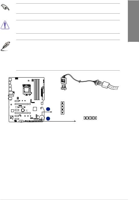
2.RGB headers (4-pin RGB_HEADER1/2)
These headers are for RGB LED strips.
These RGB headers support 5050 RGB multi-color LED strips (12V/G/R/B), with a maximum power rating of 3A (12V), and no longer than 3 m.
Before you install or remove any component, ensure that the ATX power supply is switched off or the power cord is detached from the power supply. Failure to do so may cause severe damage to the motherboard, peripherals, or components.
• Actual lighting and color will vary with LED strip.
•If your LED strip does not light up, check if the RGB LED extension cable and the RGB LED strip is connected in the correct orientation, and the 12V connector is aligned with the 12V header on the motherboard.
•The LED strip will only light up when the system is operating.
•The LED strips are purchased separately.
RGB_HEADER2
+12V RGB_HEADER1
B
+12V G R B
TUF Z390-PLUS GAMING (WI-FI) RGB_HEADER connectors
Chapter 1
|
TUF Z390-PLUS GAMING (WI-FI) |
1-9 |

1.1.7Onboard switches
Onboard switches allow you to fine-tune performance when working on a bare or opencase system. This is ideal for overclockers and gamers who continually change settings to enhance system performance.
|
Chapter |
1. |
MemOK!_II switch (MemOK!_II) |
|||||
|
Installing DIMMs that are not compatible with the motherboard may cause system |
|||||||
|
boot failure. The switch is enabled by default, allowing memory re-training when the |
|||||||
|
motherboard is unresponsive due to memory problems. The Mem_LED will light up |
|||||||
|
1 |
while re-training, and turn off when the re-training is complete. |
||||||
OFF
TUF Z390-PLUS GAMING (WI-FI) MemOK! switch
•Refer to section 1.1.8 Onboard LEDs for the exact location of the Mem_LED.
•The MemOK! II switch does not function under Windows® OS environment.
•During the tuning process, the system loads and tests pretest profiles. It takes about 30 seconds for the system to test one set of profiles. If the test fails, the system reboots and tests the next set of profiles. The system will reboot multiple times when training, once the system has completed the training process the Mem_LED will turn off, please refrain from doing anything before the Mem_LED turns off.
•Due to memory tuning requirement, the system automatically reboots when each profile is tested.
•If you turn off the computer and replace DIMMs during the tuning process, the system continues memory tuning after turning on the computer. To stop memory tuning, turn off the computer and unplug the power cord for about 5–10 seconds, then set the MemOK! II switch to disabled.
•Installing DIMMs that are not compatible with the motherboard may cause system boot failure. The switch is enabled by default, allowing memory re-training when the motherboard is unresponsive due to memory problems. The Mem_LED will light up while re-training, and turn off when the re-training is complete.
•Ensure to replace the DIMMs with ones recommended in the Memory QVL (Qualified Vendors Lists) at www.asus.com.
•The computer will reboot multiple times during the tuning process.
•We recommend that you download and update to the latest BIOS version from www.asus.com after using the MemOK! II function.
|
1-10 |
Chapter 1: Product Introduction |

1.1.8Onboard LEDs
|
1. |
Memory LED (Mem_LED) |
|
|
The Mem_LED will light up and remain lit while the MemOK! II function is in use. When |
||
|
the re-training is complete, the Mem_LED will turn off. |
1 |
|
|
Mem_LED |
Chapter |
|
TUF Z390-PLUS GAMING (WI-FI) MemOK!_LED
1.1.9Internal connectors
1.EATX power connectors (24-pin EATXPWR; 8-pin EATX12V)
These connectors are for ATX power supply plugs. The power supply plugs are designed to fit these connectors in only one orientation. Find the proper orientation and push down firmly until the connectors completely fit.
|
A |
A |
B |
||
|
EATX12V |
EATXPWR |
|||
|
DC DC DC DC |
+3 Volts |
GND |
||
|
+12V +12V +12V +12V |
+12 |
Volts |
+5 Volts |
|
|
B |
+12 |
Volts |
+5 Volts |
|
|
+5V Standby |
+5 Volts |
|||
|
Power OK |
-5 Volts |
|||
|
PIN 1 |
GND |
GND |
||
|
+5 Volts |
GND |
|||
|
GND GND GND GND |
||||
|
GND |
GND |
|||
|
+5 Volts |
PSON# |
|||
|
GND |
GND |
|||
|
+3 |
Volts |
-12 Volts |
||
|
+3 |
Volts |
+3 Volts |
||
|
PIN 1 |
TUF Z390-PLUS GAMING (WI-FI) ATX power connectors
•For a fully configured system, we recommend that you use a power supply unit (PSU) that complies with ATX 12 V Specification 2.0 (or later version) and provides a minimum power of 350 W.
•DO NOT forget to connect the 8-pin EATX12V power plug. Otherwise, the system will not boot.
•We recommend that you use a PSU with a higher power output when configuring a system with more power-consuming devices. The system may become unstable or may not boot up if the power is inadequate.
•If you want to use two or more high-end PCI Express x16 cards, use a PSU with 1000W power or above to ensure the system stability.
|
TUF Z390-PLUS GAMING (WI-FI) |
1-11 |

1 Chapter
2.USB 3.1 Gen 1 connector (20-1 pin U31G1_78, U31G1_910)
These connectors allow you to connect a USB 3.1 Gen 1 module for additional USB 3.1 Gen 1 front or rear panel ports. With an installed USB 3.1 Gen 1 module, you can enjoy all the benefits of USB 3.1 Gen 1 including faster data transfer speeds of up to 5 Gb/s, faster charging time for USB-chargeable devices, optimized power efficiency, and backward compatibility with USB 2.0.
|
A |
U31G1_910 |
B |
U31G1_78 |
|||||||||||||||||||||||||||||||||||||||||
|
Vbus |
IntA_P1_SSRX- |
D+ -D |
SSTX+ SSTX- |
SSRX+ SSRX- |
||||||||||||||||||||||||||||||||||||||||
|
PIN 1 |
||||||||||||||||||||||||||||||||||||||||||||
|
Vbus |
P2 P2 |
P2 P2 |
P2 P2 |
|||||||||||||||||||||||||||||||||||||||||
|
IntA_P2_SSRX- |
IntA_P1_SSRX+ |
|||||||||||||||||||||||||||||||||||||||||||
|
A |
GND |
IntA_P1_SSTX- |
IntA_ IntA_ GND IntA_ IntA_ GND IntA_ IntA_ Vbus |
|||||||||||||||||||||||||||||||||||||||||
|
IntA_P2_SSRX+ |
GND |
|||||||||||||||||||||||||||||||||||||||||||
|
IntA_P2_SSTX- |
IntA_P1_SSTX+ |
|||||||||||||||||||||||||||||||||||||||||||
|
IntA_P2_SSTX+ |
GND |
|||||||||||||||||||||||||||||||||||||||||||
|
GND |
IntA_P1_D- |
|||||||||||||||||||||||||||||||||||||||||||
|
IntA_P2_D- |
IntA_P1_D+ |
PIN 1 |
||||||||||||||||||||||||||||||||||||||||||
|
IntA_P2_D+ |
GND |
GND IntA P1 D+ IntA P1 D- GND IntA P1 SSTX+ IntA P1 SSTXGND IntA P1 SSRX+ IntA P1 SSRXVbus |
||||||||||||||||||||||||||||||||||||||||||
B
TUF Z390-PLUS GAMING (WI-FI) USB 3.1 Gen 1 connectors
The USB 3.1 Gen 1 module is purchased separately.
3.USB 2.0 connector (10-1 pin USB1112, 4 pin USB13)
These connectors are for USB 2.0 ports. Connect the USB module cable to these connectors, then install the module to a slot opening at the back of the system chassis. These USB connectors comply with USB 2.0 specification that support up to 480 Mb/s connection speed.
USB13 USB1112
PIN 1
GND
USB_P13+
USB_P13-
USB+5V
PIN 1
|
USB+5V USB P12- |
USB P12+ GND NC |
||||||
|
USB+5V USB P11- |
USB P11+ GND |
TUF Z390-PLUS GAMING (WI-FI) USB2.0 connectors
DO NOT connect a 1394 cable to the USB connectors. Doing so will damage the motherboard!
The USB 2.0 module is purchased separately.
|
1-12 |
Chapter 1: Product Introduction |
 Loading…
-
Драйверы
34
-
Инструкции по эксплуатации
1

ASUS TUF Z390-PLUS GAMING (WI-FI) инструкция по эксплуатации
(86 страниц)
- Языки:Французский
-
Тип:
PDF -
Размер:
4.97 MB -
Описание:
TUF Z390-PLUS GAMING (WI-FI) User’s Manual ( French )
Просмотр
На NoDevice можно скачать инструкцию по эксплуатации для ASUS TUF Z390-PLUS GAMING (WI-FI). Руководство пользователя необходимо для ознакомления с правилами установки и эксплуатации ASUS TUF Z390-PLUS GAMING (WI-FI). Инструкции по использованию помогут правильно настроить ASUS TUF Z390-PLUS GAMING (WI-FI), исправить ошибки и выявить неполадки.
Посмотреть инструкция для Asus TUF Z390-Plus бесплатно. Руководство относится к категории материнские платы, 2 человек(а) дали ему среднюю оценку 6.1. Руководство доступно на следующих языках: английский. У вас есть вопрос о Asus TUF Z390-Plus или вам нужна помощь? Задайте свой вопрос здесь
Не можете найти ответ на свой вопрос в руководстве? Вы можете найти ответ на свой вопрос ниже, в разделе часто задаваемых вопросов о Asus TUF Z390-Plus.
Инструкция Asus TUF Z390-Plus доступно в русский?
К сожалению, у нас нет руководства для Asus TUF Z390-Plus, доступного в русский. Это руководство доступно в английский.
Не нашли свой вопрос? Задайте свой вопрос здесь