![]()
970A-G43 series
MS-7693 (v3.x) Mainboard
Europe version
G52-76931XB
Preface
Copyright Notice
The material in this document is the intellectual property of MICRO-STAR INTERNA — TIONAL.
 We take every care in the preparation of this document, but no guarantee is given as to the correctness of its contents. Our products are under continual improvement and we reserve the right to make changes without notice.
Trademarks
All trademarks in this manual are properties of their respective owners.
MSI® is registered trademark of Micro-Star Int’l Co.,Ltd.
NVIDIA® is registered trademark of NVIDIA Corporation.
ATI® is registered trademark of AMD Corporation.
AMD® is registered trademarks of AMD Corporation.
Intel® is registered trademarks of Intel Corporation.
Windows® is registered trademarks of Microsoft Corporation.
AMI® is registered trademark of American Megatrends Inc.
Award® is a registered trademark of Phoenix Technologies Ltd.
Sound Blaster® is registered trademark of Creative Technology Ltd.
Realtek® is registered trademark of Realtek Semiconductor Corporation.
JMicron® is registered trademark of JMicron Technology Corporation.
Netware® is registered trademark of Novell, Inc.
Lucid® is trademark of LucidLogix Technologies, Ltd.
VIA® is registered trademark of VIA Technologies, Inc.
ASMedia® is registered trademark of ASMedia Technology Inc.
iPad, iPhone, and iPod are trademarks of Apple Inc.
|
Revision |
History |
|
|
Revision |
Revision History |
Date |
|
V3.0 |
First release for Europe version |
2012/ 12 |
ii
MS-7693
Technical Support

 Support
If a problem arises with your system and no solution can be obtained from the user’s manual, please contact your place of purchase or local distributor. Alternatively, please try the following help resources for further guidance.
Visit the MSI website for technical guide, BIOS updates, driver updates, and other information:
http://www.msi.com/service/download/
Contact our technical staff at:
http://support.msi.com
Safety Instructions

Always read the safety instructions carefully.
Keep this User’s Manual for future reference.
Keep this equipment away from humidity.
Lay this equipment on a reliable flat surface before setting it up.
The openings on the enclosure are for air convection hence protects the equipment from overheating. DO NOT COVER THE OPENINGS.
Make sure the voltage of the power source is at 110/220V before connecting the equipment to the power inlet.
Place the power cord such a way that people can not step on it. Do not place anything over the power cord.
Always Unplug the Power Cord before inserting any add-on card or module.
All cautions and warnings on the equipment should be noted.
Never pour any liquid into the opening that can cause damage or cause electrical shock.
If any of the following situations arises, get the equipment checked by service personnel:
The power cord or plug is damaged.
Liquid has penetrated into the equipment.
The equipment has been exposed to moisture.
The equipment does not work well or you can not get it work according to User’s Manual.
The equipment has been dropped and damaged.
The equipment has obvious sign of breakage.
DONOTLEAVETHISEQUIPMENTINANENVIRONMENTABOVE60oC(140oF), IT MAY DAMAGE THE EQUIPMENT.
Preface
iii
Preface
FCC
 -B Radio Frequency
 Interference
 Statement
This equipment has been tested and found to comply with the limits for a Class B digital device, pursuant to Part 15 of the FCC Rules. These limits are designed to provide reasonable protection against harmful interference in a residential installation. This equipment generates, uses and can radiate radio frequency energy and, if not installed and used in accordance with the instructions, may cause harmful interference to radio communications. However, there is no guarantee that interference will not occur in a particular installation. If this equipment does cause harmful interference to radio or television reception, which can be determined by turning the equipment off and on, the user is encouraged to try to correct the interference by one or more of the measures listed below.
Reorient or relocate the receiving antenna.
Increase the separation between the equipment and receiver.
Connect the equipment into an outlet on a circuit different from that to which the receiver is connected.
Consult the dealer or an experienced radio/television technician for help. Notice 1
The changes or modifications not expressly approved by the party responsible for compliance could void the user’s authority to operate the equipment.
Notice 2
Shielded interface cables and A.C. power cord, if any, must be used in order to comply with the emission limits.
VOIR LA NOTICE D’INSTALLATION AVANT DE RACCORDER AU RESEAU.
Micro-Star International
MS-7693
This device complies with Part15 ofthe FCCRules.Operationis subject tothefollowing two conditions:
1)this device may not cause harmful interference, and
2)this device must accept any interference received, including interference that may cause undesired operation.
CE Conformity
 Conformity
Hereby, Micro-Star International CO., LTD declares that this device is in compliance with the essential safety requirements and other relevant provisions set out in the European Directive.
iv
MS-7693
Radiation Exposure Statement

 Statement
This equipment complies with FCC radiation exposure limits set forth for an uncontrolled environment. This equipment and its antenna should be installed and operated with minimum distance 20 cm between the radiator and your body. This equipment and its antenna must not be co-located or operating in conjunction with any other antenna or transmitter.
European Community Compliance Statement

 Community Compliance Statement
The equipment complies with the RF Exposure Requirement 1999/519/EC, Council Recommendation of 12 July 1999 on the limitation of exposure of the general public to electromagnetic fields (0–300GHz). This wireless device complies with the R&TTE Directive.
Taiwan Wireless Statements
率、加大功率或變更原設計之特性及功能。
電通信。低功率射頻電機須忍受合法通信或工業、科學及醫療用電波輻射性電機設備之 干擾。
:
Japan VCCI Class B Statement
 Class B Statement
B
VCCIB
Korea Warning Statements
Preface

Preface
Battery Information

European Union:
Batteries, battery packs, and accumulators should not be disposed of as unsorted household waste. Please use the public collection system to return, recycle, or treat them in compliance with the local regulations.
Taiwan:
For better environmental protection, waste batteries should be collected separately for recycling or special disposal.
California, USA:
The button cell battery may contain perchlorate material and requires special handling when recycled or disposed of in California.
For further information please visit: http://www.dtsc.ca.gov/hazardouswaste/perchlorate/
CAUTION: There is a risk of explosion, if battery is incorrectly replaced.
Replace only with the same or equivalent type recommended by the manufacturer.
Chemical Substances Information
 Substances Information
Incompliancewithchemicalsubstancesregulations,suchastheEUREACHRegulation (Regulation EC No. 1907/2006 of the European Parliament and the Council), MSI provides the information of chemical substances in products at:
http://www.msi.com/html/popup/csr/evmtprtt_pcm.html
vi

MS-7693
WEEE (Waste Electrical and Electronic Equipment) Statement
 (Waste Electrical

 and Electronic
 Equipment)
 Statement
ENGLISH


To protect the global environment and as an environmentalist, MSI must re-
mind you that…
Under the European Union (“EU”) Directive on Waste Electrical and Electron-
ic Equipment, Directive 2002/96/EC, which takes effect on August 13, 2005,  products of “electrical and electronic equipment” cannot be discarded as municipal wastes anymore, and manufacturers of covered electronic equipment
will be obligated to take back such products at the end of their useful life. MSI will comply with the product take back requirements at the end of life of MSI-branded products that are sold into the EU. You can return these products to local collection points.
DEUTSCH
Hinweis von MSI zur Erhaltung und Schutz unserer Umwelt
Gemäß der Richtlinie 2002/96/EG über Elektround Elektronik-Altgeräte dürfen Elektro- und Elektronik-Altgeräte nicht mehr als kommunale Abfälle entsorgt werden. MSI hat europaweit verschiedene Sammelund Recyclingunternehmen beauftragt, die in die Europäische Union in Verkehr gebrachten Produkte, am Ende seines Lebenszyklus zurückzunehmen. Bitte entsorgen Sie dieses Produkt zum gegebenen Zeitpunkt ausschliesslich an einer lokalen Altgerätesammelstelle in Ihrer Nähe.
FRANÇAIS

En tant qu’écologiste et afin de protéger l’environnement, MSI tient à rappeler ceci…
Au sujet de la directive européenne (EU) relative aux déchets des équipement électriques et électroniques, directive 2002/96/EC, prenant effet le 13 août 2005, que les produits électriques et électroniques ne peuvent être déposés dans les décharges ou tout simplement mis à la poubelle. Les fabricants de ces équipements seront obligés de récupérer certains produits en fin de vie. MSI prendra en compte cette exigence relative au retour des produits en fin de vie au sein de la communauté européenne. Par conséquent vous pouvez retourner localement ces matériels dans les points de collecte.
РУССКИЙ
Компания MSI предпринимает активные действия по защите окружающей среды, поэтому напоминаем вам, что….
В соответствии с директивой Европейского Союза (ЕС) по предотвращению загрязнения окружающей среды использованным электрическим и электронным оборудованием (директива WEEE 2002/96/EC), вступающей в силу 13
августа 2005 года, изделия, относящиеся к электрическому и электронному оборудованию, не могут рассматриваться как бытовой мусор, поэтому производители вышеперечисленного электронного оборудования обязаны принимать его для переработки по окончании срока службы. MSI обязуется соблюдать требования по приему продукции, проданной под маркой MSI на территории EC, в переработку по окончании срока службы. Вы можете вернуть эти изделия в специализированные пункты приема.
vii
Preface

Preface
ESPAÑOL


MSI como empresa comprometida con la protección del medio ambiente, recomienda:
Bajo la directiva 2002/96/EC de la Unión Europea en materia de desechos y/o equipos electrónicos, con fecha de rigor desde el 13 de agosto de 2005, los productos clasificados como “eléctricos y equipos electrónicos” no pueden ser depositados en los contenedores habituales de su municipio, los fabricantes de equipos electrónicos, están obligados a hacerse cargo de dichos productos al termino de su período de vida. MSI estará comprometido con los términos de recogida de sus productos vendidos en la Unión Europea al final de su periodo de vida. Usted debe depositar estos productos en el punto limpio establecido por el ayuntamiento de su localidad o entregar a una empresa autorizada para la recogida de estos residuos.
NEDERLANDS
Om het milieu te beschermen, wil MSI u eraan herinneren dat….
De richtlijn van de Europese Unie (EU) met betrekking tot Vervuiling van Electrische en Electronische producten (2002/96/EC), die op 13 Augustus 2005 in zal gaan kunnen niet meer beschouwd worden als vervuiling. Fabrikanten van dit soort producten worden verplicht om producten retour te nemen aan het eind van hun levenscyclus. MSI zal overeenkomstig de richtlijn handelen voor de producten die de merknaam MSI dragen en verkocht zijn in de EU. Deze goederen kunnen geretourneerd worden op lokale inzamelingspunten.
SRPSKI
Da bi zaštitili prirodnu sredinu, i kao preduzeće koje vodi računa o okolini i prirodnoj sredini, MSI mora da vas podesti da…
Po Direktivi Evropske unije (“EU”) o odbačenoj ekektronskoj i električnoj opremi, Direktiva 2002/96/EC, koja stupa na snagu od 13. Avgusta 2005, proizvodi koji spadaju pod “elektronsku i električnu opremu” ne mogu više biti odbačeni kao običan otpad i proizvođači ove opreme biće prinuđeni da uzmu natrag ove proizvode na kraju njihovog uobičajenog veka trajanja. MSI će poštovati zahtev o preuzimanju ovakvih proizvoda kojima je istekao vek trajanja, koji imaju MSI oznaku i koji su prodati u EU. Ove proizvode možete vratiti na lokalnim mestima za prikupljanje.
POLSKI
Aby chronić nasze środowisko naturalne oraz jako firma dbająca o ekologię, MSI przypomina, że…
Zgodnie z Dyrektywą Unii Europejskiej (“UE”) dotyczącą odpadów produktów elektrycznych i elektronicznych (Dyrektywa 2002/96/EC), która wchodzi w życie 13 sierpnia 2005, tzw. “produkty oraz wyposażenie elektryczne i elektroniczne “ nie mogą być traktowane jako śmieci komunalne, tak więc producenci tych produktów będą zobowiązani do odbierania ich w momencie gdy produkt jest wycofywany z użycia. MSI wypełni wymagania UE, przyjmując produkty (sprzedawane na terenie Unii Europejskiej) wycofywane z użycia. Produkty MSI będzie można zwracać w wyznaczonych punktach zbiorczych.
viii

MS-7693
TÜRKÇE

Çevreci özelliğiyle bilinen MSI dünyada çevreyi korumak için hatırlatır:
Avrupa Birliği (AB) Kararnamesi Elektrik ve Elektronik Malzeme Atığı, 2002/96/EC Kararnamesi altında 13 Ağustos 2005 tarihinden itibaren geçerli olmak üzere, elektrikli ve elektronik malzemeler diğer atıklar gibi çöpe atılamayacak ve bu elektonik cihazların üreticileri, cihazların kullanım süreleri bittikten sonra ürünleri geri toplamakla yükümlü olacaktır. Avrupa Birliği’ne satılan MSI markalı ürünlerin kullanım süreleri bittiğinde MSI ürünlerin geri alınması isteği ile işbirliği içerisinde olacaktır. Ürünlerinizi yerel toplama noktalarına bırakabilirsiniz.
ČESKY
Záleží nám na ochraně životního prostředí — společnost MSI upozorňuje…
Podle směrnice Evropské unie (“EU”) o likvidaci elektrických a elektronických výrobků 2002/96/EC platné od 13. srpna 2005 je zakázáno likvidovat “elektrické a elektronické výrobky” v běžném komunálním odpadu a výrobci elektronických výrobků, na které se tato směrnice vztahuje, budou povinni odebírat takové výrobky zpět po skončení jejich životnosti. Společnost MSI splní požadavky na odebírání výrobků značky MSI, prodávaných v zemích EU, po skončení jejich životnosti. Tyto výrobky můžete odevzdat v místních sběrnách.
MAGYAR
Annak érdekében, hogy környezetünket megvédjük, illetve környezetvédőként fellépve az MSI emlékezteti Önt, hogy …
Az Európai Unió („EU”) 2005. augusztus 13-án hatályba lépő, az elektromos és elektronikus berendezések hulladékairól szóló 2002/96/EK irányelve szerint az elektromos és elektronikus berendezések többé nem kezelhetőek lakossági hulladékként, és az ilyen elektronikus berendezések gyártói kötelessé válnak az ilyen termékek visszavételére azok hasznos élettartama végén. Az MSI betartja a termékvisszavétellel kapcsolatos követelményeket az MSI márkanév alatt az EU-n belül értékesített termékek esetében, azok élettartamának végén. Az ilyen termékeket a legközelebbi gyűjtőhelyre viheti.
ITALIANO

Per proteggere l’ambiente, MSI, da sempre amica della natura, ti ricorda che….
In base alla Direttiva dell’Unione Europea (EU) sullo Smaltimento dei Materiali Elettrici ed Elettronici, Direttiva 2002/96/EC in vigore dal 13 Agosto 2005, prodotti appartenenti alla categoria dei Materiali Elettrici ed Elettronici non possono più essere eliminati come rifiuti municipali: i produttori di detti materiali saranno obbligati a ritirare ogni prodotto alla fine del suo ciclo di vita. MSI si adeguerà a tale Direttiva ritirando tutti i prodotti marchiati MSI che sono stati venduti all’interno dell’Unione Europea alla fine del loro ciclo di vita. È possibile portare i prodotti nel più vicino punto di raccolta
Preface
ix

Preface
Contents
|
Copyright |
Notice |
ii |
|
Trademarks |
ii |
|
|
Revision |
History |
ii |
|
Technical |
Support |
iii |
|
Safety Instructions |
iii |
|
|
FCC-B Radio Frequency Interference Statement |
iv |
|
|
CE Conformity |
iv |
|
|
Radiation Exposure Statement |
v |
|
|
European Community Compliance Statement |
v |
|
|
Taiwan Wireless Statements |
v |
|
|
Japan VCCI Class B Statement |
v |
|
|
Korea Warning Statements |
v |
|
|
Battery Information |
vi |
|
|
Chemical Substances Information |
vi |
|
|
WEEE (Waste Electrical and Electronic Equipment) Statement |
vii |
|
|
English |
En-1 |
Mainboard Specifications En-2
Connectors Quick Guide En-4
Back Panel Quick Guide En-6
CPU (Central Processing Unit) En-8
Mounting Screw Holes En-11
Power Supply En-12
Memory En-13
Expansion Slot En-15
Internal Connectors En-16
Jumper En-23
Drivers and Utilities En-24
BIOS Setup En-25
![]()
MS-7693
Deutsch De-1
Spezifikationen De-2 Anschlussübersicht De-4 Rücktafel-Übersicht De-6 CPU (Prozessor) De-8 Schraubenlöcher für die Montage De-11 Stromversorgung De-12 Speicher De-13 Erweiterungssteckplatz De-15 Interne Anschlüsse De-16 Steckbrücken De-23 Treiber und Dienstprogramme De-24 BIOS Setup De-25
Français Fr
Fr -1
-1
Spécifications Fr-2 Guide Rapide Des Connecteurs Fr-4 Guide rapide du panneau arrière Fr-6 Processeur : CPU Fr-8 Trous Taraudés de Montage Fr-11 Connecteurs d’alimentation Fr-12 Mémoire Fr-13 Emplacements d’extension Fr-15 Connecteurs internes Fr-16 Cavaliers Fr-23 Pilotes et Utilitaires Fr-24 Réglage BIOS Fr-25
Preface
xi

Preface
Русский Ru-1
Характеристики системной платы Ru-2 Краткое руководство по разъемам Ru-4 Справочное руководство по разъемам Ru-5 Краткое руководство по работе с задней панелью Ru-6 CPU (Центральный процессор) Ru-8 Отверстия под установочные винты Ru-11 Электропитание Ru-12 Память Ru-13 Слоты расширения Ru-15 Внутренние разъемы Ru-16 Перемычки Ru-23 Драйверы и утилиты Ru-24 Настройка BIOS Ru-25
xii

MS-7693 Mainboard
Mainboard Specifications
Processor Support
■Supports AMD® FXTM/ PhenomTM II/ AthlonTM II and SempronTM processors for the AM3/ AM3+ socket
HyperTransport

■ HyperTransport™ 3.0, supports up to 4.8 GT/s
Chipset
■ AMD® 970 & SB950 chipset
Memory Support
■4x DDR3 DIMMs support for DDR3-1066/ 1333/ 1600/ 1866/ 2133*(OC) MHz up to 32GB max
■Supports Dual-Channel mode
LAN
■ Supports LAN 10/ 100/ 1000 Fast Ethernet by Realtek® 8111E
Audio
■Integrated HD audio codec by Realtek® ALC887
■8-channel audio with jack sensing
■Compliant with Azalia 1.0 Spec
SATA
■ 6x SATA 6Gb/s ports by AMD® SB950
RAID
■ SATA1~6 support RAID 0/ 1/ 5/ 10 mode by AMD® SB950
USB 3.0
■2x USB 3.0 rear I/O ports & 1x USB 3.0 onboard connector by RENESAS UPD720202
Multi -GPU
-GPU
■ Supports AMD® CrossFire™ Technology
En-2
Connectors & Buttons
■Back panel
—1x PS/2 keyboard port
—1x PS/2 mouse port
—6x USB 2.0 ports
—2x USB 3.0 ports
—1x LAN port
—6x audio ports
■On-Board
—3x USB 2.0 connectors
—1x USB 3.0 connector
—1x TPM Module connector
—1x Front Panel Audio connector
—1x Chassis Intrusion connector
—1x Serial port connector
Slots
■2x PCIe 2.0 x16 slots
—PCI_E2 supports up to PCIe x16 speed
—PCI_E4 supports up to PCIe x4 speed
■2x PCIe 2.0 x1 slots
■2x PCI slots
Form
 Factor

■ ATX (30.5 cm X 22.5 cm)
Mounting Screw Holes
■ 6x mounting holes
For the latest information about CPU, please visit
http://www.msi.com/service/cpu-support/
For more information on compatible components, please visit
http://www.msi.com/service/test-report/
If you need to purchase accessories and request the part numbers, you could search the product web page and find details on our web address http://www.msi.com/index. php
Engl shi
En-3

MS-7693 Mainboard
Connectors Quick Guide |
|||
|
DIMM1 |
|||
|
SYSFAN2 |
CPU1 |
DIMM2 |
|
|
DIMM3 |
|||
|
JPWR2 |
CPUFAN |
DIMM4 |
|
|
Back Panel |
|||
|
JPWR1 |
|||
|
PCI_E1 |
SYSFAN1 |
||
|
PCI_E2 |
|||
|
PCI_E3 |
|||
|
JCI1 |
SATA5_6 |
||
|
PCI1 |
SATA3_4 |
||
|
PCI_E4 |
SATA2 |
||
|
SATA1 |
|||
|
PCI2 |
JBAT1 |
||
|
JFP2 |
|||
|
JAUD1 |
JUSB4 |
||
|
JFP1 |
|||
|
JCOM1 |
JUSB3 |
||
|
JTPM1 |
JUSB2 |
||
|
JUSB1 |
|||
|
En-4 |

Connectors Reference Guide
|
Port Name |
Port Type |
Page |
|
Back Panel |
I/O Ports |
En-6 |
|
CPU1 |
AM3/ AM3+ CPU Socket |
En-9 |
|
CPUFAN,SYSFAN1~2 |
Fan Power Connectors |
En-17 |
|
DIMM1~4 |
DDR3 Memory Slots |
En-13 |
|
JAUD1 |
Front Panel Audio Connector |
En-21 |
|
JBAT1 |
Clear CMOS Jumper |
En-23 |
|
JCI1 |
Chassis Intrusion Connector |
En-19 |
|
JCOM1 |
Serial Port Connector |
En-21 |
|
JFP1, JFP2 |
Front Panel Connectors |
En-18 |
|
JPWR1 |
ATX 24-pin Power Connector |
En-12 |
|
JPWR2 |
ATX 8-pin Power Connector |
En-12 |
|
JTPM1 |
TPM Module Connector |
En-22 |
|
JUSB1~3 |
USB 2.0 Expansion Connectors |
En-19 |
|
JUSB4 |
USB 3.0 Expansion Connector |
En-20 |
|
PCI_E1, E3 |
PCIe x1 Expansion Slots |
En-15 |
|
PCI_E2, E4 |
PCIe x16 Expansion Slots |
En-15 |
|
PCI1, 2 |
PCI Expansion Slots |
En-15 |
|
SATA1~6 |
SATA 6Gb/s Connectors |
En-16 |
Engl shi
En-5

MS-7693 Mainboard
Back Panel Quick Guide
 Quick Guide
|
PS/2 |
LAN |
|||
|
Mouse |
||||
|
USB 2.0 Port |
USB 2.0 Port |
USB 3.0 Port |
Line-In |
RS-Out |
|
Line-Out CS-Out |
||||
|
PS/2 |
USB 2.0 Port |
Mic |
SS-Out |
|
|
Keyboard |
Mouse/Keyboard
The standard PS/2® mouse/keyboard DIN connector is for a PS/2® mouse/keyboard.
USB 2.0 Port
The USB 2.0 port is for attaching USB 2.0 devices such as keyboard, mouse, or other USB 2.0-compatible devices.
USB 3.0 Port
USB 3.0 port is backward-compatible with USB 2.0 devices. It supports data transfer rate up to 5 Gbit/s (SuperSpeed).
 Important
In order to use USB 3.0 devices, you must connect to a USB 3.0 port. If a USB cable is used, it must be USB 3.0 compliant.
En-6

|
LAN |
||||
|
The standard RJ-45 LAN jack is for connecting to a Yellow |
Green/ Orange |
|||
|
Local Area Network (LAN). |
||||
|
LED |
Color |
LED State |
Condition |
|
|
Left |
Yellow |
Off |
LAN link is not established. |
|
|
On(Steady) |
LAN link is established. |
|||
|
On(flashing) |
The computer is communicating with another computer on the network. |
|||
|
Right |
Green |
Off |
10 Mbits/sec data rate |
|
|
On |
100 Mbits/sec data rate |
|||
|
Orange |
On |
1000 Mbits/sec data rate |
Audio Ports
These connectors are used for audio devices. The color of the jack refers to the function of the connector.
■Blue-Line in: Used for connecting external audio outputting devices.
■GreenLine out: Used as a connector for speakers or headphone.
■PinkMic: Used as a connector for a microphone.
■Black- RS-Out: Rear surround sound line out in 4/ 5.1/ 7.1 channel mode.
■Orange- CS-Out: Center/ subwoofer line out in 5.1/ 7.1 channel mode.
■Gray- SS-Out: Side surround sound line out in 7.1 channel mode.
Engl shi
En-7
MS-7693 Mainboard
CPU (Central Processing Unit)
 Processing Unit)
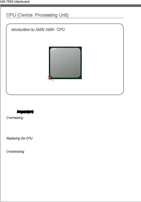
Introduction to AM3/ AM3+
 CPU
CPU
The surface of CPU. Remember to apply some thermal paste on it for better heat dispersion.
Gold arrow
 Important
Overheating
Overheating can seriously damage the CPU and mainboard. Always make sure the cooling fans work properly to protect the CPU from overheating. Be sure to apply an even layer of thermal paste (or thermal tape) between the CPU and the heatsink to enhance heat dissipation.
Replacing the CPU
When replacing the CPU, always turn off the system’s power supply and unplug the power supply’s power cord to ensure the safety of the CPU.
Overclocking
This mainboard is designed to support overclocking. Before attempting to overclock, please make sure that all other system components can tolerate overclocking. Any attempt to operate beyond product specifications is not recommend. MSI does not guarantee the damages or risks caused by inadequate operation beyond product specifications.
En-8
![]()
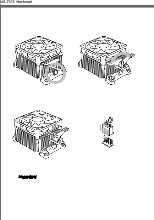
CPU & Cooler Installation
When you are installing the CPU, make sure the CPU has a cooler attached on the top to prevent overheating. Meanwhile, do not forget to apply some thermal paste on CPU before installing the heat sink/cooler fan for better heat dispersion.
Follow the steps below to install the CPU & cooler correctly. Wrong installation will cause the damage of your CPU & mainboard.
|
1. Pull the lever sideways away from |
2. Look for the gold arrow of the CPU. |
|
the socket. Make sure to raise the |
Thegoldarrowshouldpointasshown |
|
lever up to a 90-degree angle. |
in the picture. The CPU can only fit in |
|
the correct orientation. |
Engl shi
3.If the CPU is correctly installed, the pins should be completely embedded into the socket and can not be seen. Please note that any violation of the correct installation procedures may cause permanent damages to your mainboard.
4.Press the CPU down firmly into the socket and close the lever. As the CPU is likely to move while the lever is being closed, always close the leverwithyourfingerspressingtightly on top of the CPU to make sure the CPU is properly and completely embedded into the socket.
En-9
MS-7693 Mainboard
5.Position the cooling set onto the retention mechanism.
Hook one end of the clip to hook first.
7. Fasten down the lever.
6.Then press down the other end of the clip to fasten the cooling set on the top of the retention mechanism.
Locate the Fix Lever and lift up it .
8.AttachtheCPUFancabletotheCPU fan connector on the mainboard.
 Important
•While disconnecting the Safety Hook from the fixed bolt, it is necessary to keep an eye on your fingers, because once the Safety Hook is disconnected from the fixed bolt, the fixed lever will spring back instantly.
•Confirm that the CPU cooler has formed a tight seal with the CPU before booting your system.
•Please refer to the documentation in the CPU cooler package for more details about CPU cooler installation.
En-10
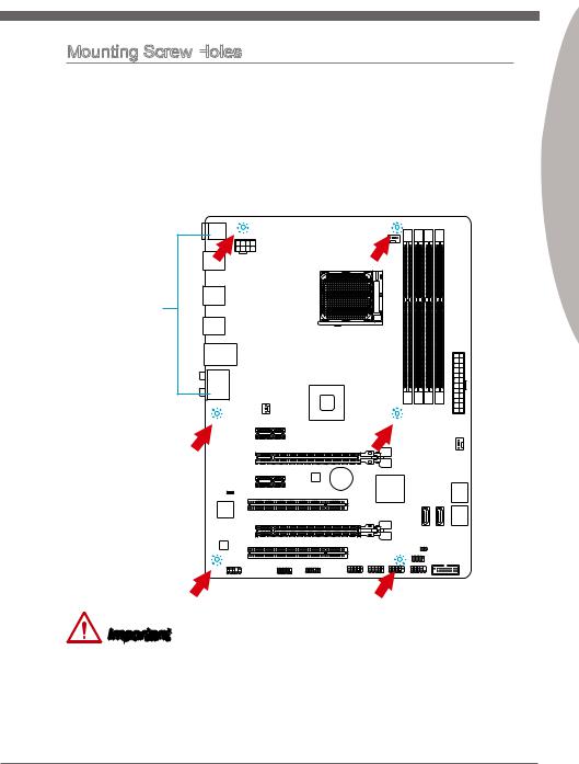
Mounting Screw Holes

When installing the mainboard, first install the necessary mounting stands required for a mainboard onngithe mounting plate in your computer case. If there is an I/O back plate that came with the computer case, please replace it with the I/O backplate that came
|
with the mainboard package. The I/O backplate should snap easily into the computer |
|
|
toward |
|
|
i |
|
|
case without the need for any screws. Align the mounting plate’s mounting stands with |
|
|
th |
|
|
the screw holes on the mainboard and secure the mainboard with the screws provided |
|
|
with your computerthe |
case. The locations of the screw holes on the mainboard are shown |
|
below. For more information, please refer to the manual that came with the computer |
|||
|
case. |
holesnei |
||
|
thewonup |
|||
|
I/O |
the |
||
|
should |
I/OThe |
||
|
backplate |
the |
||
|
rear l |
|||
|
ports |
|||
|
of |
|||
|
. |
should |
||
|
computer |
|||
|
be |
|||
|
fac |
|||
|
They .case |
Important
•Install the mainboard on a flat surface free from unnecessary debris.
•To prevent damage to the mainboard, any contact between the mainboard circuitry and the computer case, except for the mounting stands, is prohibited.
•Please make sure there are no loose metal components on the mainboard or within the computer case that may cause a short circuit of the mainboard.
Engl shi
En-11

MS-7693 Mainboard
Power Supply
JPWR1:
 ATX 24-pin Power Connector
This connector allows you to connect an ATX 24-pin power supply. To connect the ATX 24-pin power supply, align the power supply cable with the connector and firmly press the cable into the connector. If done correctly, the clip on the power cable should be hooked on the mainboard’s power connector.
|
12 |
||||||||||||||||||||
|
11 |
. |
|||||||||||||||||||
|
7 |
10 |
. +3. |
||||||||||||||||||
|
+12V |
||||||||||||||||||||
|
9 . |
3 |
|||||||||||||||||||
|
8 |
. |
|||||||||||||||||||
|
V |
||||||||||||||||||||
|
6 . |
||||||||||||||||||||
|
5 . |
||||||||||||||||||||
|
1 |
4 |
. +5 |
||||||||||||||||||
|
3 . |
Ground |
|||||||||||||||||||
|
2 |
. +5 |
24 |
||||||||||||||||||
|
.GroundV |
||||||||||||||||||||
|
. |
V |
|||||||||||||||||||
|
. +3 |
3 |
|||||||||||||||||||
|
+3 |
||||||||||||||||||||
|
. |
23. |
|||||||||||||||||||
|
V |
||||||||||||||||||||
|
3 |
. |
|||||||||||||||||||
|
Ground |
||||||||||||||||||||
|
. +5 |
V |
|||||||||||||||||||
|
+5 |
||||||||||||||||||||
|
+5 |
V |
V |
||||||||||||||||||
|
.Ground |
||||||||||||||||||||
|
. |
— |
|||||||||||||||||||
|
13. |
— |
ON |
||||||||||||||||||
|
+3 12V |
# |
|||||||||||||||||||
|
3 |
||||||||||||||||||||
|
V |
JPWR2: ATX 8-pin Power Connector
This connector provides 12V power to the CPU.
|
4 |
||||||
|
. |
||||||
|
3 |
Ground |
|||||
|
. |
||||||
|
2 |
Ground |
|||||
|
. |
||||||
|
1 |
Ground |
|||||
|
. |
||||||
|
Ground |
||||||
|
8 |
||||||
|
5 |
. |
|||||
|
7 |
+12V |
|||||
|
. |
||||||
|
6 |
+12V |
|||||
|
. |
||||||
|
+12V |
||||||
|
. |
||||||
|
+12V |
 Important
Make sure that all the power cables are securely connected to a proper ATX power supply to ensure stable operation of the mainboard.
En-12

En-13

MS-7693 Mainboard
Installing Memory Modules
1.Unlock the DIMM slot by pushing the mounting clips to the side. Vertically insert the memory module into the DIMM slot. The memory module has an off-center notch on the bottom that will only allow it to fit one way into the DIMM slot.
2.Push the memory module deep into the DIMM slot. The plastic clips at each side of the DIMM slot will automatically close when the memory module is properly seated and an audible click should be heard.
3.Manually check if the memory module has been locked in place by the DIMM slot’s side clips.
Notch
Volt
En-14

Expansion Slot

 Slot
Slot
Thismainboardcontainsnumerousportsforexpansioncards,suchasdiscretegraphics or audio cards.
PCIe Slot
The PCIe slot supports the PCIe interface expansion card.
PCIe 2.0 x16 Slot
PCIe 2.0 x1 Slot
PCI Slot
Slot
The PCI slot supports additional LAN, SCSI, USB, and other add-on cards that comply with PCI specifications.
32-bit PCI Slot
 Important
When adding or removing expansion cards, always turn off the power supply and unplug the power supply power cable from the power outlet. Read the expansion card’s documentation to check for any necessary additional hardware or software changes.
PCI Interrupt
 Request Routing
IRQ, or interrupt request lines, are hardware lines over which devices can send interrupt requests to the processor. The PCI IRQ pins are typically connected to the PCI bus pins as followed:
|
Order1 |
Order2 |
Order3 |
Order4 |
|
|
PCI1 |
INT E# |
INT F# |
INT G# |
INT H# |
|
PCI2 |
INT F# |
INT G# |
INT H# |
INT E# |
Engl shi
En-15
MS-7693 Mainboard
Internal Connectors

 Connectors
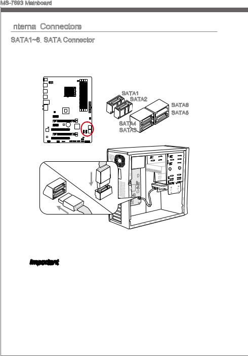
SATA1~6:
 SATA Connector
This connector is a high-speed SATA interface port. Each connector can connect to one SATA device. SATA devices include disk drives (HDD), solid state drives (SSD), and optical drives (CD/ DVD/ Blu-Ray).
SATA1
SATA2
SATA6
 SATA5
SATA5
SATA4
SATA3
* The MB layout in this figure is for reference only.
 Important
•Many SATA devices also need a power cable from the power supply. Such devices include disk drives (HDD), solid state drives (SSD), and optical drives (CD / DVD / Blu-Ray). Please refer to the device’s manual for further information.
•Many computer cases also require that large SATA devices, such as HDDs, SSDs, and optical drives, be screwed down into the case. Refer to the manual that came with your computer case or your SATA device for further installation instructions.
•Please do not fold the SATA cable at a 90-degree angle. Data loss may result during transmission otherwise.
•SATA cables have identical plugs on either sides of the cable. However, it is recommended that the flat connector be connected to the mainboard for space saving purposes.
En-16

CPUFAN,SYSFAN1~2:
 Fan
Fan
 Power Connectors
The fan power connectors support system cooling fans with +12V. If the mainboard has a System Hardware Monitor chipset on-board, you must use a specially designed fan with a speed sensor to take advantage of the CPU fan control. Remember to connect all system fans. Some system fans may not connect to the mainboard and will instead connect to the power supply directly. A system fan can be plugged into any available system fan connector.
CPUFAN
|
1 |
|||||||||||||
|
2 . |
|||||||||||||
|
3 |
. G |
||||||||||||
|
+ r |
|||||||||||||
|
4 |
. |
1 o |
|||||||||||
|
S |
2 u |
||||||||||||
|
. |
e |
n |
|||||||||||
|
C |
n V |
d |
|||||||||||
|
o |
s |
||||||||||||
|
n |
o |
||||||||||||
|
t |
r |
||||||||||||
|
r |
|||||||||||||
|
o |
|||||||||||||
|
l |
|||||||||||||
SYSFAN1
|
1 |
|||||||||||||
|
2 . |
|||||||||||||
|
+12VGround |
|||||||||||||
|
3 . |
|||||||||||||
|
4 . |
|||||||||||||
|
Sensor |
|||||||||||||
|
. |
|||||||||||||
|
No |
Us |
||||||||||||
|
e |
|||||||||||||
SYSFAN2
|
1 |
||||||
|
2 . |
||||||
|
3 |
. G |
|||||
|
+ r |
||||||
|
. |
1 |
o |
||||
|
u |
||||||
|
N 2 |
n |
|||||
|
o |
d |
|||||
|
U V |
||||||
|
s |
||||||
|
e |
Important
•Please refer to your processor’s official website or consult your vendor to find recommended CPU cooling fans.
•The CPUFAN connector supports Smart Fan Control with linear mode. The Control Center II utility can be installed to automatically control the fan speeds according to the CPU’s temperature.
•If there are not enough ports on the mainboard to connect all system fans, adapters are available to connect a fan directly to a power supply.
•Before first boot up, ensure that there are no cables impeding any fan blades.
Engl shi
En-17
MS-7693 Mainboard
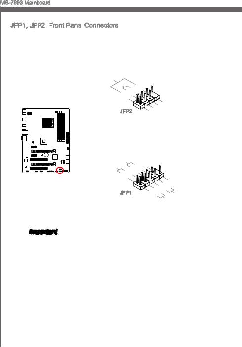
JFP1, JFP2: Front
Front Panel
Panel Connectors
These connectors connect to the front panel switches and LEDs. The JFP1 connector is compliant with the Intel® Front Panel I/O Connectivity Design Guide. When installing the front panel connectors, please use the enclosed mConnectors to simplify installation. Plug all the wires from the computer case into the mConnectors and then plug the mConnectors into the mainboard.
|
Speaker |
6 |
+ |
|||
|
Buzzer |
|||||
|
8 |
|||||
|
. |
|||||
|
4 |
. |
||||
|
— |
|||||
|
2 |
. |
||||
|
+ |
|||||
|
. |
|||||
|
— |
JFP2
|
7 |
||||||
|
3 |
5 . |
|||||
|
. No |
||||||
|
. |
Power |
|||||
|
Pi |
D |
|||||
|
1 |
Suspend |
|||||
|
. |
n |
|||||
|
Ground |
LE |
|||||
|
LE |
||||||
|
D |
|
P |
|||||||||||
|
P |
ower |
S |
10 |
||||||||
|
witch |
No |
||||||||||
|
ower |
|||||||||||
|
. |
Pi |
||||||||||
|
LE |
8 |
||||||||||
|
D |
6 |
— |
|||||||||
|
4 |
. |
. |
|||||||||
|
+ |
|||||||||||
|
2 |
. |
||||||||||
|
— |
|||||||||||
|
. |
|||||||||||
|
+ |
JFP1
|
9 |
|||||||||||||
|
1 |
. |
||||||||||||
|
7 |
Reserve |
||||||||||||
|
5 |
. |
||||||||||||
|
+ |
|||||||||||||
|
3 |
. |
||||||||||||
|
— |
|||||||||||||
|
. |
|||||||||||||
|
. |
— |
Reset |
d |
||||||||||
|
+ |
|||||||||||||
|
HDD |
|||||||||||||
|
LE |
S |
||||||||||||
|
D |
witch |
||||||||||||
 Important
•On the connectors coming from the case, pins marked by small triangles are positive wires. Please use the diagrams above and the writing on the mConnectors to determine correct connector orientation and placement.
•The majority of the computer case’s front panel connectors will primarily be plugged into JFP1.
En-18
![]()
JCI1: Chassis Intrusion
 Connector
This connector connects to the chassis intrusion switch cable. If the computer case is opened, the chassis intrusion mechanism will be activated. The system will record this intrusion and a warning message will flash on screen. To clear the warning, you must enter the BIOS utility and clear the record.
|
2 |
|||||||||||||||||||||||
|
. |
|||||||||||||||||||||||
|
1 |
G |
||||||||||||||||||||||
|
. |
r |
||||||||||||||||||||||
|
C |
o |
||||||||||||||||||||||
|
I |
u |
||||||||||||||||||||||
|
N |
n |
||||||||||||||||||||||
|
T |
d |
||||||||||||||||||||||
|
R |
|||||||||||||||||||||||
|
U |
|||||||||||||||||||||||
Engl shi
JUSB1~3:
 USB 2.0 Expansion
 Connector
This connector is designed for connecting high-speed USB peripherals such as USB HDDs, digital cameras, MP3 players, printers, modems, and many others.
|
10 |
||||||
|
6 |
8 . |
|||||
|
. |
. NC |
|||||
|
USB1Ground |
||||||
|
4 |
. |
|||||
|
. |
+ |
|||||
|
VCUSB1 |
||||||
|
2 |
||||||
|
C |
— |
|
9 |
|||||||
|
5 |
. |
||||||
|
. No |
|||||||
|
7 |
|||||||
|
. |
USB0Ground |
||||||
|
Pin |
|||||||
|
3 . |
+ |
||||||
|
VCUSB0 |
|||||||
|
1 |
|||||||
|
. |
C |
||||||
|
— |
* The MB layout in this figure is for reference only.
USB 2.0 Bracket (optional)
Important
Note that the VCC and GND pins must be connected correctly to avoid possible damage.
En-19

MS-7693 Mainboard
JUSB4:
 USB 3.0 Expansion
 Connector
The USB 3.0 port is backwards compatible with USB 2.0 devices. It supports data transfer rates up to 5Gbits/s (SuperSpeed).
11
|
20. |
|||||||||||||
|
19. |
N |
P |
|||||||||||
|
18. |
|||||||||||||
|
16.. |
Power |
n |
|||||||||||
|
15 |
17 |
USB3 |
i |
||||||||||
|
. |
_ |
||||||||||||
|
13. |
USB3 |
_ |
|||||||||||
|
USB3Ground |
_ |
||||||||||||
|
14. |
R |
||||||||||||
|
12. |
USB3 |
_ |
R |
X |
|||||||||
|
C |
|||||||||||||
|
Ground |
TX |
||||||||||||
|
USUSB2 |
_ TX |
_ |
|||||||||||
|
_ |
|||||||||||||
|
. |
|||||||||||||
|
B . |
C |
||||||||||||
|
2 |
0 |
_ |
|||||||||||
|
0 |
— |
D |
|||||||||||
|
. |
|||||||||||||
|
+ |
|
1 |
|||||||||||||||||
|
. |
|||||||||||||||||
|
. Po |
wer |
||||||||||||||||
|
U |
|||||||||||||||||
|
SB3_ |
|||||||||||||||||
|
SB3 |
R |
||||||||||||||||
|
SB3Ground |
_ |
X |
X |
||||||||||||||
|
U |
SB3 |
R |
_ |
||||||||||||||
|
_ |
D |
DN |
|||||||||||||||
|
. |
. |
Ground |
C |
_ |
|||||||||||||
|
TX |
P |
||||||||||||||||
|
SBSB2. |
_ |
TX_ |
|||||||||||||||
|
_ |
|||||||||||||||||
|
Ground |
C |
_ |
|||||||||||||||
|
2 |
0 |
||||||||||||||||
|
. |
D DN |
||||||||||||||||
|
0 |
— |
_ |
P |
||||||||||||||
|
+ |
* The MB layout in this figure is for reference only.
USB 3.0 Bracket (optional)
 Important
•Note that the VCC and GND pins must be connected correctly to avoid possible damage.
•To use a USB 3.0 device, you must connect the device to a USB 3.0 port through an optional USB 3.0 compliant cable.
En-20

JAUD1: Front
Front
 Panel
Panel Audio Connector
This connector allows you to connect the front audio panel located on your computer case. This connector is compliant with the Intel® Front Panel I/O Connectivity Design Guide.
|
10 |
||||||||||||||||
|
8 . |
||||||||||||||||
|
4 |
. NoHead |
|||||||||||||||
|
6 . |
||||||||||||||||
|
. MI |
Pi |
P |
||||||||||||||
|
2 |
NC |
D |
hone |
|||||||||||||
|
C n |
||||||||||||||||
|
. |
||||||||||||||||
|
Ground |
etection |
Detection |
||||||||||||||
|
9 |
||||||||||
|
3 . |
. |
|||||||||
|
Head |
||||||||||
|
7 |
||||||||||
|
5 . |
||||||||||
|
. |
HeadSENSE |
P |
||||||||
|
. MI |
P |
hone |
||||||||
|
MI |
||||||||||
|
1 |
C |
_ |
||||||||
|
C |
R |
SEN |
||||||||
|
hone |
D |
|||||||||
|
L |
L |
|||||||||
|
R |
||||||||||
JCOM1:
 Serial
 Port Connector
This connector is a 16550A high speed communication port that sends/receives 16 bytes FIFOs. You can attach a serial device.
|
1 |
||||||||||
|
0 |
||||||||||
|
8 . |
||||||||||
|
6 |
. N |
|||||||||
|
C |
o |
|||||||||
|
. |
T |
P |
||||||||
|
4 |
D |
S |
i |
|||||||
|
S |
n |
|||||||||
|
2 |
. |
|||||||||
|
D |
R |
|||||||||
|
. |
T |
|||||||||
|
S |
R |
|||||||||
|
I |
||||||||||
|
N |
|
9 |
|||||||||
|
7 |
. |
||||||||
|
R |
|||||||||
|
5 |
. |
I |
|||||||
|
R |
|||||||||
|
3 |
. |
T |
|||||||
|
G |
|||||||||
|
1 |
. |
r |
S |
||||||
|
S |
o |
||||||||
|
. |
O |
u |
|||||||
|
D |
U |
n |
|||||||
|
C |
d |
||||||||
|
T |
|||||||||
|
D |
Engl shi
En-21

MS-7693 Mainboard
JTPM1:

 TPM Module Connector
This connector connects to a TPM (Trusted Platform Module). Please refer to the TPM security platform manual for more details and usages.
TPM module (optional)
|
14. |
|||||
|
1012. |
|||||
|
4 |
6 . |
No Ground |
|||
|
. 5V |
GroundP |
||||
|
. |
8 . |
||||
|
Serial |
|||||
|
. |
3V |
P in |
|||
|
Iower |
|||||
|
3 |
|||||
|
2 . |
|||||
|
3V St P |
RQ |
||||
|
ower |
|||||
|
andby |
p |
||||
|
ower |
|
13. |
||||||||||||||||||||||
|
5 |
911. |
LP |
F |
|||||||||||||||||||
|
. LP |
LPC |
|||||||||||||||||||||
|
1 |
7 . |
a |
C |
rame |
||||||||||||||||||
|
3 |
LP |
a |
||||||||||||||||||||
|
. |
Ca |
C |
a |
|||||||||||||||||||
|
. LP |
ddres |
|||||||||||||||||||||
|
. |
C |
ddres |
||||||||||||||||||||
|
LP |
C |
s |
d |
|||||||||||||||||||
|
C |
ddres |
s |
& |
|||||||||||||||||||
|
C |
R |
s |
& |
ata |
||||||||||||||||||
|
eset |
s |
& |
||||||||||||||||||||
|
lock |
& |
d |
ata |
p |
||||||||||||||||||
|
d |
at |
p |
in3 |
|||||||||||||||||||
|
at |
a |
|||||||||||||||||||||
|
a |
p in2 |
|||||||||||||||||||||
|
p in1 |
||||||||||||||||||||||
|
in0 |
* The MB layout in this figure is for reference only.
En-22

Jumper
JBAT1:
 Clear CMOS Jumper
There is CMOS RAM onboard that is external powered from a battery located on the mainboard to save system configuration data. With the CMOS RAM, the system can automatically boot into the operating system (OS) every time it is turned on. If you want to clear the system configuration, set the jumpers to clear the CMOS RAM.
1 1
Keep Data Clear Data
Engl shi
 Important
YoucancleartheCMOSRAMbyshortingthisjumperwhilethesystemisoff.Afterwards, open the jumper . Do not clear the CMOS RAM while the system is on because it will damage the mainboard.
En-23

MS-7693 Mainboard
Drivers and Utilities
After you install the operating system you will need to install drivers to maximize the performance of the new computer you just built. MSI mainbaord comes with a Driver Disc. Drivers allow the computer to utilize your mainboard more efficiently and take advantage of any special features we provide.
You can protect your computer from viruses by installing the bundled security program. The bundle also includes a variety of powerful and creative utilities.
Total
 Installer
Total Installer is very easy to use and does a great job of finding necessary drivers. Please follow the steps below to install drivers and utilities for your new computer.
1.Insert MSI Driver Disc into the optical drive. The setup screen will automatically appear if autorun is enabled in OS.
2.Click Total Installer. A popup dialog will appear listing all necessary drivers.
Click here
3.Select all checkbox on driver listing dialog.
4.Click Install


 button.
5.The software installation will then be in progress, after it has finished it will prompt you to restart.
6.Click OK button to finish.
7.Restart your computer.
You can also use the same method to install the utilities.
En-24

BIOS Setup
CLICK BIOS II is developed by MSI that provides a graphical user interface for setting parameters of BIOS by using the mouse and the keybord.
WiththeCLICKBIOSII,userscanchangeBIOSsettings,monitorprocessortemperature, select the boot device priority and view system information such as the processor name, DRAM capacity, the OS version and the BIOS version. Users can import and export parameters data for backup or sharing with friends. After connecting to Internet, users can browse the internet, check mail and live update your system.
Entering

Power on the computer and the system will start POST (Power On Self Test) process. When the message below appears on the screen, press <DEL> key to enter Setup.
Press DEL key to enter Setup Menu, F11
 to enter Boot Menu
If the message disappears before you respond and you still wish to enter Setup, restart the system by turning it OFF and On or pressing the RESET button. You may also restart the system by simultaneously pressing <Ctrl>, <Alt>, and <Delete> keys.
 Important
The items under each BIOS category described in this section are under continuous update for better system performance. Therefore, the description may be slightly different from the latest BIOS and should be held for reference only.
Engl shi
En-25

MS-7693 Mainboard
Overview
After entering CLICK BIOS II, the following screen is displayed.
|
Language |
System |
|
|
Temperature |
information |
|
|
monitor |
Boot menu |
|
|
Mode |
||
|
selection |
Boot device |
|
|
priority bar |
||
|
BIOS menu |
||
|
selection |
||
|
BIOS menu |
||
|
selection |
||
|
Menu display |
||
|
Important |
The pictures in this guide are for reference only and may vary from the product you purchased. Please refer to the actual screens of your system for detailed information.
Temperature monitor
This block shows the temperature of the processor and the mainboard.System information
This block shows the time, date, CPU name, CPU frequency, DRAM frequency, DRAM capacity and the BIOS version.
BIOS menu selection
These blocks are used to select menus of BIOS. The following options are available:
■SETTINGS — Use this menu to specify your settings for chipset features, boot device.
■OC — This menu contains items of the frequency and voltage adjustments. Increasing the frequency can get better performance, however high frequency and heat can cause instability, we do not recommend general users to overclock.
■ECO
 — This menu is related to energy-saving settings.
■BROWSER — This feature is used to enter the MSI Winki web browser.
■UTILITIES — This menu contains utilities for backup and update.
En-26

■SECURITY — The security menu is used to keep unauthorized people from making any changes to the settings. You can use these security features to protect your system.
Boot device priority bar
You can move the device icons to change the boot priority.Boot menu
This button is used to open a boot menu. Click the item to boot the system from the device instantly.
Mode selection
This feature allows you to load presets of energy saving or overclocking.Menu display
This area provides BIOS settings and information to be configured.Language

This allows you to select the language of the BIOS setting.
Boot device priority bar
This bar shows the priority of the boot devices. The lighted icons indicate that the devices are available.
High priority  Low priority Click and draw the icon to left or right to specify the boot priority.
Sub-Menu
If you find a point symbol to the left of certain fields, that means a sub-menu can be launched for additional options. You can use the arrow keys or
mouse to highlight the field and press <Enter> or double-click the left mouse button to enter the sub-menu. If you want to return to the previous menu, just press <Esc> or click the right mouse button.
General
 Help
Help

The General Help screen lists the appropriate keys to use for navigation. You can call up this screen from any menu by simply pressing <F1>. Press <Esc> to exit the Help screen.
Engl shi
En-27

MS-7693 Mainboard
Operation
CLICK BIOS II allows you to control BIOS settings with the mouse and the keyboard. The following table lists and describes the hot keys and the mouse operations.
|
Hot key |
Mouse |
Description |
|
<↑↓→← > |
Select Item |
|
|
Move the cursor |
||
|
<Enter> |
Select Icon/ Field |
|
|
Click/ Double-click |
||
|
the left button |
||
|
<Esc> |
Jump to the Exit menu or return to the previous from |
|
|
a submenu |
||
|
Click the right |
||
|
button |
||
|
<+> |
Increase the numeric value or make changes |
|
|
<-> |
Decrease the numeric value or make changes |
|
|
<F1> |
General Help |
|
|
<F4> |
CPU Specifications |
|
|
<F5> |
Enter Memory-Z |
|
|
<F6> |
Load optimized defaults |
|
|
<F8> |
OC Profile Load From USB drive |
|
|
<F9> |
OC Profile Save to USB drive |
|
|
<F10> |
Save Change and Reset |
|
|
<F12> |
Save a screenshot to a FAT/FAT32 USB drive |
En-28
![]()
OC Menu
This menu is for advanced users who want to overclock the mainboard.
Engl shi
Important
•Overclocking your PC manually is only recommended for advanced users.
•Overclocking is not guaranteed, and if done improperly, can void your warranty or severely damage your hardware.
•If you are unfamiliar with overclocking, we advise you to use OC Genie for easy overclocking.
Current CPU/ DRAM Frequency

These items show the current clocks of CPU and Memory speed. Read-only.
Adjust CPU FSB
 Frequency

Allows you to set the CPU FSB frequency (in MHz). You may overclock the CPU by adjusting this value. Please note that overclocking behavior and stability is not guaranteed.
Adjust CPU Ratio
Controls the multiplier that is used to determine internal clock speed of the processor. This feature can only be changed if the processor supports this function.
Adjusted CPU Frequency

It shows the adjusted CPU frequency. Read-only.
Adjust CPU-NB Ratio
This item is used to adjust CPU-NB ratio.
En-29

MS-7693 Mainboard
Adjusted CPU-NB Frequency

It shows the adjusted CPU-NB frequency. Read-only.
CPU Smart Protection
CPUSmartProtectionisamechanismofCPUoverheatingprotection.Itwillautomatically reduce the clock when the CPU temperature gets too high.
Unlock CPU Core
This item is used to unlock the CPU core. Please refer to the procedures below for CPU core unlocked in BIOS setup.
Enter “OC” and set “Unlock CPU Core” to [Enabled].
Save changes and exit the BIOS setup.
System restart.
Fail
Success
Set “Adjust CPU-NB Ratio” and “HT Link Speed” to [x8].
Clear CMOS data.
You will see the “X4” (quad core) or “X2” (dual core for Sempron series only) during POST.
The CPU does not support CPU core unlocking, please leave the default settings for system.
AMD Phenom(tm) II X4 Processor
AMD Sempron(tm) II X2 Processor
 Important
•This CPU core unlocked behavior depends on the CPU ability/ characteristic, and it is not guaranteed.
•Depend on CPU’s characteristic, once you get instable scenario, please restore the default settings for system.
•You can also check the core numbers in performance tab of Windows task manager.
CPU Core Control
This item allows you to select the number of active processor cores. When set to [Auto], the CPU will operate under the default number of cores.
AMD Turbo Core Technology
This technology automatically increases the frequency of active CPU cores to improve performance.
Adjust Max Turbo Core Ratio
This item allows you to adjust the max turbo core ratio.
En-30

DRAM Frequency

This item allows you to adjust the DRAM frequency.
Adjusted DRAM Frequency

It shows the adjusted DRAM frequency. Read-only.DRAM Timing Mode
Select whether DRAM timing is controlled by the SPD (Serial Presence Detect) EEPROM on the DRAM module. Setting to [Auto] enables DRAM timings and the following “Advanced DRAM Configuration” sub-menu to be determined by BIOS based on the configurations on the SPD. Selecting [Link] or [Unlink] allows users to configure the DRAM timings for each channel and the following related “Advanced DRAM Configuration” sub-menu manually.
Advanced DRAM Configuration
Press <Enter> to enter the sub-menu.
Command Rate
This setting controls the DRAM command rate.
tCL
Controls CAS latency which determines the timing delay (in clock cycles) of starting a read command after receiving data.
tRCD
Determines the timing of the transition from RAS (row address strobe) to CAS (column address strobe). The less clock cycles, the faster the DRAM performance.
tRP
Controls number of cycles for RAS (row address strobe) to be allowed to pre-charge. If insufficient time is allowed for RAS to accumulate before DRAM refresh, the DRAM may fail to retain data. This item applies only when synchronous DRAM is installed in the system.
tRAS
Determines the time RAS (row address strobe) takes to read from and write to memory cell.
tRFC
This setting determines the time RFC takes to read from and write to a memory cell.
tWR
Determines minimum time interval between end of write data burst and the start of a pre-charge command. Allows sense amplifiers to restore data to cell.
tWTR
Determines minimum time interval between the end of write data burst and the start of a column-read command; allows I/O gating to overdrive sense amplifies before read command starts.
Engl shi
En-31

MS-7693 Mainboard
tRRD
Specifies the active-to-active delay of different banks.
tRTP
Time interval between a read and a precharge command.tFAW
This item is used to set the tFAW (four activate window delay) timing.tWCL
This item is used to set the tWCL (Write CAS Latency) timing.
tCKE
This item is used to set the Pulse Width for DRAM module.
tRTL
This item is used to set Round Trip Latency settings.
tXP
Exit Power Down with DLL on to and valid command; Exit Precharge Power Down with DLL frzon to commands not requiring a locked DLL.
==Advanced Timing Configuration==
Follwing items are used to set the read/ write timings for memory.
tRRDR
Read-Read Different Rank, same DIMM.
tRRDD
Read-Read Different Rank.
tWWDR
Write-Write Different Rank, same DIMM.
tWWDD
Write-Write Different Rank.
tRWDRDD
Read-Write Different Ranks same or Different DIMM.
tWRDRDD
Write-Read Different Ranks same or Different DIMM.
tRWSR
Read-Write Same Rank.
HT

 Link
Link
 Speed
Speed
ThisitemallowsyoutosettheHyper-TransportLinkspeed.Settingto[Auto],thesystem will detect the HT link speed automatically.
Adjusted HT

 Link
Link
 Frequency

It shows the adjusted HT Link frequency. Read-only.
En-32

HT

 Link
Link
 Control

Press <Enter> to enter the sub-menu.
HT
 Incoming/
 Outgoing Link
 Width
Width
These items allow you to set the Hyper-Transport Link width. Setting to [Auto], the system will detect the HT link width automatically.
DRAM Voltage/ SB Voltage/ NB Voltage/ CPU Voltage/ CPU-NB Voltage These items are used to adjust the voltage of CPU, Memory and chipset.
Spread Spectrum
This function reduces the EMI (Electromagnetic Interference) generated by modulating clock generator pulses.
 Important
•If you do not have any EMI problem, leave the setting at [Disabled] for optimal system stability and performance. But if you are plagued by EMI, select the value of Spread Spectrum for EMI reduction.
•The greater the Spread Spectrum value is, the greater the EMI is reduced, and the systemwillbecomelessstable.ForthemostsuitableSpreadSpectrumvalue, please consult your local EMI regulation.
•Remember to disable Spread Spectrum if you are overclocking because even a slight jitter can introduce a temporary boost in clock speed which may just cause your overclocked processor to lock up.
Overclocking Profiles
Press <Enter> to enter the sub-menu.
Overclocking Profile 1/ 2/ 3/ 4/ 5/ 6 Press <Enter> to enter the sub-menu.
Set Name for Overclocking Profile 1/ 2/ 3/ 4/ 5/ 6 Give a name by typing in this item.
Save Overclocking Profile 1/ 2/ 3/ 4/ 5/ 6
Save the current overclocking settings to ROM for selected profile.
Load/ Clear Overclocking Profile 1/ 2/ 3/ 4/ 5/ 6 Load/ Clear the stored profile settings from ROM.
Overclocking Profile Save
Save the current overclocking settings to USB flash disk.
Overclocking Profile Load
Load the stored settings from USB flash disk.MEMORY-Z
Press <Enter> to enter the sub-menu. This sub-menu highlights all the settings and timings of your DIMMs. This information will vary by model and is read-only. You can also access this information at any time by pressing [F5]. Press <Enter> to enter the sub-menu.
Engl shi
En-33

MS-7693 Mainboard
DIMM1~4 Memory SPD
Press <Enter> to enter the sub-menu. The sub-menu displays the informations of installed memory.
CPU Specifications
Press <Enter> to enter the sub-menu. This sub-menu highlights all the key features of your CPU. The information will vary by model and is read-only. You can also access this information at any time by pressing [F4]. Press <Enter> to enter the sub-menu.
CPU Technology Support
Press <Enter> to enter the sub-menu. The sub-menu shows the installed CPU technologies. Read only.
CPU Features

Press <Enter> to enter the sub-menu.
AMD Cool’n’Quiet
The Cool’n’Quiet technology can effectively and dynamically lower CPU speed and power consumption.
 Important
To ensure that Cool’n’Quiet function is activated and will be working properly, it is required to double confirm that:
•Run BIOS Setup, and select OC. Under OC Menu, find CPU Features > AMD Cool’n’Quiet, and set this item to “Enabled”.
•Enter Windows, and select [Start]->[Settings]->[Control Panel]->[Power Options]. Enter Power Options Properties tag, and select Minimal Power Management under Power schemes.
C1E Support
Enable this item to reduce the CPU power consumption while idle. Not all processors support Enhanced Halt state (C1E).
SVM Mode
This item allows you to enable/disable the AMD SVM (Secure Virtual Machine) Mode.
IOMMU
 Mode
Mode
This item allows you to enable/disable the IOMMU (I/O Memory Management Unit) for I/O virtualization.
En-34

Updating the BIOS with Live
 Update
This section tells you how to update the BIOS by using the Live Update utility before entering Operating System. Live Update will update the BIOS automatically when connecting to the Internet. To update the BIOS with the Live Update utility:
|
1. Click Live Update button |
on the BIOS UTILITIES menu. (The Winki must be |
|
installed). |
2.Setup the connection by click the setting button if necessary.
3.Click the next button .
.
4.Live Update will automatically detect the version of BIOS and download the appropriate file.
5. Click the confirm button to update the BIOS.
Engl shi
 Important
Do not update the BIOS if your system is running fine.
En-35
 Loading…
-
Драйверы
3
-
Инструкции по эксплуатации
1

MSI 970A-G43 инструкция по эксплуатации
(156 страниц)
- Языки:Русский
-
Тип:
PDF -
Размер:
12.21 MB -
Описание:
Материнская плата AMD
Просмотр
На NoDevice можно скачать инструкцию по эксплуатации для MSI 970A-G43. Руководство пользователя необходимо для ознакомления с правилами установки и эксплуатации MSI 970A-G43. Инструкции по использованию помогут правильно настроить MSI 970A-G43, исправить ошибки и выявить неполадки.
Page 1 — 970A-G43 seres
970A-G43 seres MS-7693 (v3.x) ManboardG52-76931X8
Page 2
xPrefaceMS-7693Preface PrefaceMS-7693Preface CONTENTS▍Copyrght Notce …
Page 3
PrefaceMS-7693Preface xPrefaceMS-7693Preface Chapter 2 BIOS Setup …2-
Page 5
Thank you for choosng the 970A-G43 Seres (MS-7693 v3.X) ATX manboard. The 970A-G43 Seres manboards are based on AMD® 970 & SB950 chpsets for
Page 6
1-2Gettng StartedPackng ContentsManboardDrver / Utlty DVDUser GudeBack IO SheldSATA Cable* These pctures are for reference only and may vary
Page 7
1-3MS-7693Chapter 1Assembly PrecautonsThe components ncluded n ths package are prone to damage from electrostatc dscharge (ESD). Please ad
Page 8
1-4Gettng StartedManboard SpeccatonsProcessor SupportSupports AMD® FXTM/ PhenomTM II/ AthlonTM II and SempronTM processors for the AM3/ AM3+ sock
Page 9
1-5MS-7693Chapter 1Connectors & Buttons Back panel1x PS/2 keyboard port1x PS/2 mouse port6x USB 2.0 ports2x USB 3.0 ports1x LAN port6x audo por
Page 10 — CONTENTS
1-6Gettng StartedConnectors Quck GudeBack PanelCPU1CPUFANDIMM2JUSB3JPWR1SATA3_4 JAUD1JBAT1PCI_E1JUSB4JCOM1DIMM1JFP2JPWR2JCI1JFP1SYSFAN1SYSFAN2DIMM
Page 11
1-7MS-7693Chapter 1Connectors Reference GudePort Name Port Type PageBack Panel I/O Ports 1-8CPU1 AM3/ AM3+ CPU Socket 1-11CPUFAN,SYSFAN1~2
Page 12
PrefaceMS-7693Preface PrefaceMS-7693Preface Copyrght NotceThe materal n ths document s the ntellectual property of MICRO-STAR INTERNA-TIONAL
Page 13 — Gettng Started
1-8Gettng StartedBack Panel Quck GudeMouse/KeyboardThe standard PS/2® mouse/keyboard DIN connector s for a PS/2® mouse/keyboard.USB 2.0 PortThe US
Page 14 — Optonal Accessores
1-9MS-7693Chapter 1LAN The standard RJ-45 LAN jack s for connectng to a Local Area Network (LAN). LED Color LED State CondtonLeft Yellow O LAN l
Page 15 — Assembly Precautons
1-10Gettng StartedGold arrowCPU (Central Processng Unt) ImportantOverheatngOverheatng can serously damage the CPU and manboard. Always make sur
Page 16 — Manboard Speccatons
1-11MS-7693Chapter 1CPU & Cooler InstallatonWhen you are nstallng the CPU, make sure the CPU has a cooler attached on the top to prevent overhe
Page 17
1-12Gettng StartedPoston the coolng set onto the retenton mechansm. Hook one end of the clp to hook rst.5. Then press down the o
Page 18 — Connectors Quck Gude
1-13MS-7693Chapter 1Mountng Screw HolesWhen nstallng the manboard, rst nstall the necessary mountng stands requred for a manboard on the moun
Page 19 — Connectors Reference Gude
1-14Gettng StartedPower SupplyJPWR1: ATX 24-pn Power ConnectorThs connector allows you to connect an ATX 24-pn power supply. To connect the ATX 24
Page 20 — Back Panel Quck Gude
1-15MS-7693Chapter 1MemoryThese DIMM slots are used for nstallng memory modules. For more nformaton on compatble components, please vst http://
Page 21
1-16Gettng StartedInstallng Memory ModulesUnlock the DIMM slot by pushng the mountng clps to the sde. Vertcally nsert the memory module nto t
Page 23
PrefaceMS-7693Preface PrefaceMS-7693Preface Techncal SupportIf a problem arses wth your system and no soluton can be obtaned from the user’s
Page 24 — Important
1-18Gettng StartedVdeo/ Graphcs Cards If avalable, ths manboard takes advantage of the CPU’s ntegrate graphcs processor, but dscrete vdeo ca
Page 25 — Mountng Screw Holes
1-19MS-7693Chapter 1AMD CrossFre™ (Mult-GPU) TechnologyAMD CrossFre™ s a mult-GPU performance gamng platform. By lnkng together two o
Page 26 — Power Supply
1-20Gettng StartedBoot up the computer and nstall the drvers and software ncluded n your vdeo card package. For more nformaton, please refer t
Page 27
1-21MS-7693Chapter 1Internal ConnectorsSATA1~6: SATA ConnectorThs connector s a hgh-speed SATA nterface port. Each connector can connect to one SA
Page 28 — Installng Memory Modules
1-22Gettng StartedCPUFAN,SYSFAN1~2: Fan Power ConnectorsThe fan power connectors support system coolng fans wth +12V. If the manboard has a System
Page 29 — Expanson Slot
1-23MS-7693Chapter 1JFP1, JFP2: Front Panel ConnectorsThese connectors connect to the front panel swtches and LEDs. The JFP1 connector s complant w
Page 30 — Vdeo/ Graphcs Cards
1-24Gettng StartedJCI1: Chasss Intruson ConnectorThs connector connects to the chasss ntruson swtch cable. If the computer case s opened, the
Page 31
1-25MS-7693Chapter 1JUSB4: USB 3.0 Expanson ConnectorThe USB 3.0 port s backwards compatble wth USB 2.0 devces. It supports data trans
Page 32
1-26Gettng StartedJAUD1: Front Panel Audo ConnectorThs connector allows you to connect the front audo panel located on your computer case. Ths co
Page 33 — Internal Connectors
1-27MS-7693Chapter 1JTPM1: TPM Module ConnectorThs connector connects to a TPM (Trusted Platform Module). Please refer to the TPM securty platform m
Page 34
vPrefaceMS-7693Preface PrefaceMS-7693Preface CE ConformtyHereby, Mcro-Star Internatonal CO., LTD declares that ths devce s n complance
Page 35
1-28Gettng StartedJumperJBAT1: Clear CMOS JumperThere s CMOS RAM onboard that s external powered from a battery located on the manboard to save sy
Page 36
1-29MS-7693Chapter 1Drvers and UtltesAfter you nstall the operatng system you wll need to nstall drvers to maxmze the performance of the ne
Page 39
2-2BIOS SetupEnterngPower on the computer and the system wll start the Power On Self Test (POST) pro-cess. When the message below appears on the scr
Page 40
2-3MS-7693Chapter 2System nformatonThs block shows the tme, date, CPU name, CPU frequency, DRAM frequency, DRAM capacty and the BIOS verson.BIOS
Page 41 — Drvers and Utltes
2-4BIOS SetupOperatonCLICK BIOS II allows you to control BIOS settngs wth the mouse and the keyboard. The followng table lsts and descrbes the h
Page 42
2-5MS-7693Chapter 2SETTINGSSystem StatusSystem DateThs allows you to set the system date that you want (usually the current date).The format s <d
Page 43 — BIOS Setup
2-6BIOS SetupSystem InformatonShows detaled system nformaton, ncludng CPU type, BIOS verson, and Memory (read only).AdvancedPCI Subsystem Sett
Page 44 — Overvew
2-7MS-7693Chapter 2HD Audo ControllerThs tem allows you to enable/ dsable the HD audo controller. HPETThe HPET (Hgh Precson Event Tmers) s a
Page 45 — Boot devce prorty bar
PrefaceMS-7693Preface vPrefaceMS-7693Preface Radaton Exposure StatementThs equpment comples wth FCC radaton exposure lmts set forth for
Page 46 — Operaton
2-8BIOS SetupPower Management SetupPress <Enter> to enter the sub-menu. EuP 2013Energy Usng Products Lot 6 2013 (EUP) reduces power consumpton
Page 47 — SETTINGS
2-9MS-7693Chapter 2Date/ HH:MM:SSIf Resume By RTC Alarm s set to [Enabled], the system wll automatcally resume (boot up) on a specc date/hour/mn
Page 48
2-10BIOS SetupSave & ExtDscard Changes and ExtThs tem s used to abandon all changes and ext setup.Save Changes and RebootThs tem s used
Page 49
2-11MS-7693Chapter 2OC ImportantOverclockng your PC manually s only recommended for advanced users.Overclockng s not guaranteed, and f done mpro
Page 50
2-12BIOS SetupAdjusted CPU-NB Frequency It shows the adjusted CPU-NB frequency. Read-only.CPU Smart ProtectonCPU Smart Protecton s a mechansm of C
Page 51
2-13MS-7693Chapter 2DRAM FrequencyThs tem allows you to adjust the DRAM frequency. Adjusted DRAM FrequencyIt shows the adjusted DRAM frequency. Read
Page 52 — Save & Ext
2-14BIOS SetuptRRDSpeces the actve-to-actve delay of derent banks. tRTPTme nterval between a read and a precharge command. tFAWThs tem s us
Page 53
2-15MS-7693Chapter 2HT Lnk ControlPress <Enter> to enter the sub-menu.HT Incomng/ Outgong Lnk WdthThese tems allow you to set the Hyper-Tr
Page 54
2-16BIOS SetupDIMM1~4 Memory SPDPress <Enter> to enter the sub-menu. The sub-menu dsplays the nformatons of nstalled memory.CPU Speccaton
Page 55
2-17MS-7693Chapter 2ECO ImportantOnce you clck the “ECO” button n the pre-set area, some tems n ECO menu wll be xed and un-adjustable.EuP 2013En
Page 56
vPrefaceMS-7693Preface PrefaceMS-7693Preface Calforna, USA: The button cell battery may contan perchlorate materal and requres specal hand
Page 57
2-18BIOS SetupBROWSERPlease nstall the MSI «Wnk» applcaton rst n the Wndows operatng system wth the MSI Drver Dsc before usng t
Page 58
2-19MS-7693Chapter 2UTILITIESHDD BackupHard dsk storage backups and restorng s one of the most common and mportant tasks. Use ths utlty to cre
Page 59
2-20BIOS SetupM-FlashBIOS Boot FunctonThs allows you to enable/ dsable the system to boot from the BIOS le nsde USB drve (FAT/ 32 format only).
Page 60 — Installng Wnk
2-21MS-7693Chapter 2Updatng the BIOS wth Lve UpdateThs secton tells you how to update the BIOS by usng the Lve Update utlty before enterng
Page 61 — UTILITIES
2-22BIOS SetupSECURITYAdmnstrator Password Set the admnstratve password that wll be requred to enter the BIOS. User Password Set the user passw
Page 62
The Realtek audo provdes 8-channel DAC. To achevethe 8-channel sound eect, the 7th and 8th channels must be plugged nto the output on the
Page 63
A-2Realtek AudoSoftware ConguratonAfter nstallng the audo drver, the “Realtek HD Audo Manager” con wll appear at the notcaton area (lower
Page 64 — SECURITY
A-3MS-7693Appendx ADevce SelectonHere you can select a audo output source to change the related optons. The “check” sgn (n orange) ndcates th
Page 65 — Realtek Audo
A-4Realtek AudoHardware Default SettngThe followng dagrams are audo back panel default settng.Backpanel audo jacks to 2-channel speakers dagra
Page 66 — Software Conguraton
A-5MS-7693Appendx ABackpanel audo jacks to 6-channel speakers dagramRearFrontCen ter & Subw ooferBackpanel audo jacks to 8-channel speakers d
Page 67 — Appendx A
PrefaceMS-7693Preface vPrefaceMS-7693Preface WEEE (Waste Electrcal and Electronc Equpment) StatementENGLISHTo protect the global envronment and
Page 69
The ntegrate one SATA host controller separately, and support RAID functon for performance and relablty. The SATA RAID provdes support for RAID
Page 70
B-2AMD RAIDRAID ConguratonCreatng and deletng RAID set and performng other RAID settng up operatons are done n the RAID BIOS. Durng boot-up,
Page 71 — AMD RAID
B-3MS-7693Appendx BVew Drves Assgnments Ths wndow dsplays the model number, capactes and assgnment of the drves phys-cally attached to the
Page 72 — RAID Conguraton
B-4AMD RAIDLD Vew / LD Dene Menu (Creatng RAID)The selecton of the RAID conguraton should be based upon factors ncludng perfor-mance, data sec
Page 73 — Appendx B
B-5MS-7693Appendx BStrpe Block Sze, the default 64KB s best for most applcatons. RAID 0 or 10 only.Ggabyte Boundary, allows use of slghtly sma
Page 74
B-6AMD RAIDThe message wll show up on the bottom, press any key to use maxmum capacty or press [Ctrl-Y] to modfy array capacty manually.6.The LD
Page 75
B-7MS-7693Appendx BDelete LD Menu (Deletng RAID)Press “3” on the man to enter the Delete LD Menu.Choose a LD No. you want to delete and press [Del]
Page 76
B-8AMD RAIDInstallng DrverNew Wndows 7/ Wndows XP Installaton The followng detals the RAID drver nstallaton whle nstallng operatng syste
Page 77
B-9MS-7693Appendx BExstng Wndows Drver Installaton Insert the MSI DVD nto the DVD-ROM drve.The DVD wll auto-run and the setup screen wll app
Page 78 — Installng Drver
vPrefaceMS-7693Preface PrefaceMS-7693Preface ESPAÑOLMSI como empresa comprometda con la proteccón del medo ambente, recomenda:Bajo la drectv
Page 80
PrefaceMS-7693Preface xPrefaceMS-7693Preface TÜRKÇEÇevrec özellğyle blnen MSI dünyada çevrey korumak çn hatırlatır:Avrupa Brlğ (AB) Kar