“Руководство по металлообработке” разработано в 2007 году. Цель настоящего руководства — обеспечение информацией, необходимой для надёжной и эффективной обработки материалов с помощью основных инструментов Sandvik Coromant.
Данное руководство рекомендуется использовать в сочетании с “Основным каталогом” и последними дополнениями к “Основному каталогу”.
В руководстве Вы узнаете о:
- — выборе оптимального метода обработки
- — выборе инструмента
- — применении и обслуживании инструмента
- — методах повышения производительности
- — о том, как устранить возникающие проблемы
- — технических характеристиках инструмента
- — формулах для расчета параметров резания
- — особенностях обработки конкретного материала
Скачать руководство полностью в архиве (zip, 90 MB)
По рубрикам:
- A. ТОЧЕНИЕ (PDF)
- B. ОТРЕЗКА И ОБРАБОТКА КАНАВОК (PDF)
- C. НАРЕЗАНИЕ РЕЗЬБЫ (PDF)
- D. ФРЕЗЕРОВАНИЕ (PDF)
- E. СВЕРЛЕНИЕ (PDF)
- F. РАСТАЧИВАНИЕ (PDF)
- G. ИНСТРУМЕНТАЛЬНАЯ ОСНАСТКА (PDF)
- H. ОБЩАЯ ИНФОРМАЦИЯ И ДРУГИЕ ВИДЫ ОБРАБОТКИ (PDF)
Премиальный дистрибьютор ведущих брендов
![]()
![]()
![]()
ООО «Инструментальные Решения» является дистрибьютором металлорежущего инструмента Sandvik Coromant, корпорации OSG (Somta) и бренда EROJET в России.
О компании Sandvik Coromant
Компания из Швеции имеет представительства в 150 странах. Сегодня компания Sandvik Coromant является ведущим мировым поставщиком инструментов и технологий для металлообрабатывающей промышленности. В течение многих лет мы вносим огромный вклад в развитие промышленности, создавая новые продукты, решения и методы, которые способствуют оптимизации производственных процессов и стимулируют творческое мышление.
Масштабные инвестиции в научные исследования и разработки, а также тесное сотрудничество с нашими заказчиками и партнёрами позволяет Sandvik Coromant создавать уникальные инновации, которые призваны стать основой для промышленных стандартов следующего периода индустриализации.
О компании EROJET
Компания Erojet основана в 2003 году. Весь инструмент производится на предприятии в промышленном парке Mizgav на севере Израиля.
Является ведущей компанией производителем резьбонарезного металорежущего инструмента, производит стандартный токарный и фрезерный инструмент для нарезания резьб различного типа и размеров.
О компании OSG (Somta)
Корпорация OSG является крупнейшим в мире производителем осевого инструмента. Основанная в 1938 году, OSG по праву гордится проверенной временем репутацией поставщика комплексных инструментальных решений для мировой промышленности.
OSG поставляет инструменты для энергетической, судостроительной, строительной промышленности, а также для производителей высокоточного оборудования, таких как медицинские приборы

Руководство по металлообработке Sandvik Coromant
(технический справочник)
Руководство по металлообработке Sandvik Coromant
(технический справочник)
Руководство по металлообработке Sandvik Coromant предлагается в формате *.pdf.
| Руководство по металлообработке Sandvik Coromant (технический справочник) | ||
| Оглавление со ссылками | 11.5 Mb | Открыть |
| Токарная обработка | 35.7 Mb | Открыть |
| Отрезка и обработка канавок | 13.1 Mb | Открыть |
| Резьбонарезание | 12.9 Mb | Открыть |
| Фрезерование | 61.8 Mb | Открыть |
| Сверление | 14.3 Mb | Открыть |
| Растачивание | 14.5 Mb | Открыть |
| Инструментальная оснастка | 22.8 Mb | Открыть |
| Материалы | 5.6 Mb | Открыть |
| Информация / Указатель | 3.1 Mb | Открыть |
Рассылка
ПНР (Пуско-наладочные работы) оборудования у Заказчиков
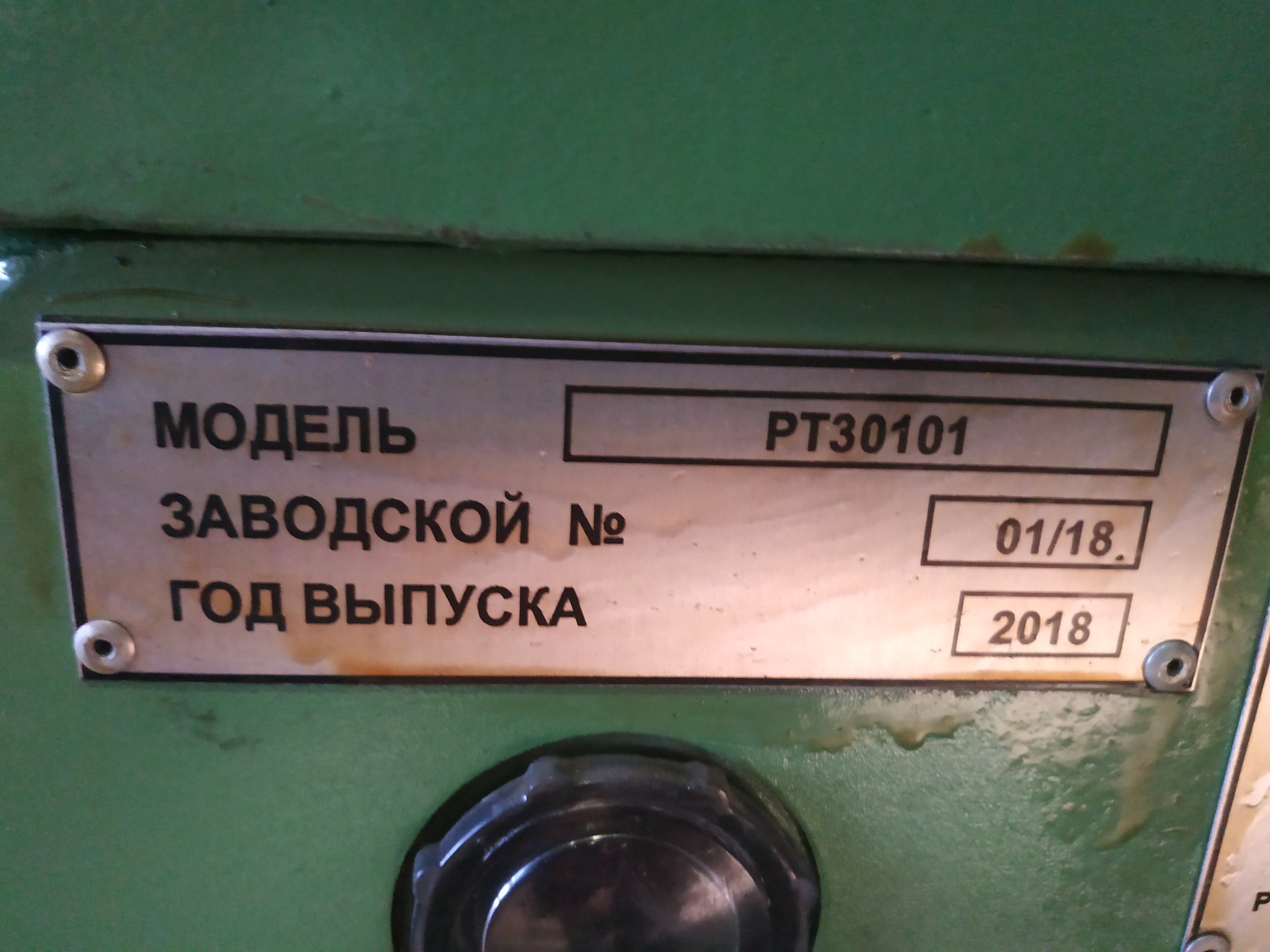
ПНР токарно-накатного станка мод. РТ30101 РЖД Тамбов
Станок специальный токарно-накатной модели РТ30101
предназначендля обработки подступичной части оси
вагонной колесной парыРУ1, РУ1Ш РУ2, РУ2Ш
ГОСТ 22780-93 (ГОСТ Р 50334-92).
ПНР токарно-накатного станка мод. РТ30101 РЖД Тамбов
ПНР ( пуско-наладочные работы) специального бандажировочного станка мод. РТ5004 для филиал РЖД г. Владимир
 специального бандажировочного станка мод. РТ5004 для филиал РЖД г. Владимир")
Бандажировочный специальный станок РТ5004
Станок бандажировочный специальный РТ5004 предназначен для бандажировки якорей стеклолентой, а также для продорожки коллекторов электрических машин.
На станке возможно бандажирование якорей электродвигателей диаметром до 800 мм и общей длиной до 3000 мм при установке в центрах передней и задней бабок.
Станок подлежат применению в локомотивных депо и заводах, занимающихся ремонтом электрических машин.
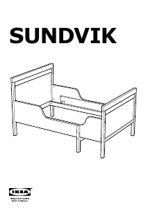
Требуется руководство для вашей IKEA SUNDVIK Каркас кровати? Ниже вы можете просмотреть и загрузить бесплатно руководство в формате PDF. Кроме того, приведены часто задаваемые вопросы, рейтинг изделия и отзывы пользователей, что позволит оптимально использовать ваше изделие. Если это не то руководство, которое вы искали, – свяжитесь с нами.
Ваше устройство неисправно, и в руководстве отсутствует решение? Перейдите в Repair Café для получения бесплатных ремонтных услуг.
Руководство

Рейтинг
Сообщите нам, что вы думаете о IKEA SUNDVIK Каркас кровати, оставив оценку продукта. Хотите поделиться вашими впечатлениями от данного изделия или задать вопрос? Вы можете оставить комментарий в нижней части страницы.
Довольны ли вы данным изделием IKEA?
Да Нет
37 голоса
Часто задаваемые вопросы
Наша служба поддержки выполняет поиск полезной информации по изделиям и отвечает на часто задаваемые вопросы. Если вы заметили неточность в наших часто задаваемых вопросах, сообщите нам об этом с помощью нашей контактной формы.
Как лучше всего разобрать мебель из IKEA? Проверенный
IKEA советует разбирать мебель, используя инструкцию по сборке в обратном порядке.
Это было полезно (17598)
У моей мебели из IKEA не достает винтика/заглушки/гвоздя. Где я могу найти замену? Проверенный
В каждом магазине IKEA есть отдел, где можно бесплатно взять винтики, заглушки и другие расходные материалы.
Это было полезно (8572)
Не могу извлечь шкант из изделия IKEA. Что делать? Проверенный
Лучше всего воспользоваться пассатижами и постараться не сжимать шкант слишком сильно, в противном случае он не будет сидеть так плотно.
Это было полезно (1403)
У меня есть каркас кровати IKEA. Согласно инструкции мне нужна центральная перекладина, но в комплекте ее нет. Что мне делать? Проверенный
Во многих кроватях IKEA используются центральные перекладины SKORVA. Их покупают отдельно в магазине.
Это было полезно (716)
Какая минимальная толщина матраса? Проверенный
Рекомендуется, чтобы все типы матрасов имели толщину не менее 16 см для обеспечения достаточного комфорта.
Это было полезно (355)
Могу ли я использовать двуспальный матрас на двуспальной кровати с индивидуально регулируемым решетчатым основанием кровати? Проверенный
Нет. Невозможно поставить двойной матрас на двуспальную кровать с индивидуальным решетчатым основанием из-за возможной разницы в высоте между обеими половинами. Каждой половине понадобится по одному матрасу. Также нельзя использовать двойной наматрасник.
Это было полезно (182)
В чем разница между каркасом кровати и коробчатой пружиной? Проверенный
Каркас кровати вмещает только матрас, но не обеспечивает демпфирования или другого комфорта. Пружинный короб — это наматрасник, наполненный металлическими витками. Пространство между змеевиками обеспечивает дополнительную вентиляцию. Поверх пружинного блока вы добавляете матрас и, возможно, наматрасник. Комбинация пружинного блока и матраса обеспечивает хорошее распределение веса и хорошую вентиляцию.
Это было полезно (137)
В чем разница между деревянным и металлическим каркасом кровати? Проверенный
Деревянные каркасы кроватей обычно прочнее металлических. Это означает, что с металлическим каркасом кровати нужно чаще проверять прочность и чаще затягивать винты.
Это было полезно (125)
-
Page 1
Original Instructions Operator’s Manual MANQA451OMEN 160615… -
Page 2
All rights reserved. No parts of this document may be reproduced or copied in any form or by any means without written permission from Sandvik. All data and information in this manual may be changed without further notice. Reservation for misprints. -
Page 3: Table Of Contents
1.12.1 Vibration levels — — — — — — — — — — — — — — — — — — — — — — — — — — — — — — — — — — — — — — — — — — — — — — — — — — — — — — — — — 37 Copyright © Sandvik Construction…
-
Page 4
3.7.4 Ignition switch E — — — — — — — — — — — — — — — — — — — — — — — — — — — — — — — — — — — — — — — — — — — — — — — — — — — — — — — — — -74 Copyright © Sandvik Construction… -
Page 5
4.6.4 To remove a gang tag — — — — — — — — — — — — — — — — — — — — — — — — — — — — — — — — — — — — — — — — — — — — — — — — — — — — 130 Copyright © Sandvik Construction… -
Page 6
6.9.2 Machine maintenance — every 1000 hours — — — — — — — — — — — — — — — — — — — — — — — — — — — — — — — — — — — — — — — 171 Copyright © Sandvik Construction… -
Page 7
8.1.2 Engine alternatives — — — — — — — — — — — — — — — — — — — — — — — — — — — — — — — — — — — — — — — — — — — — — — — — — — — — — — 206 Copyright © Sandvik Construction… -
Page 8
10.2 Hazardous substances — — — — — — — — — — — — — — — — — — — — — — — — — — — — — — — — — — — — — — — — — — — — — — — — — — — — — 211 Copyright © Sandvik Construction… -
Page 9: Safety
All machines Operator’s manual Safety…
-
Page 10: Safety Principles
All machines Operator — 1.1 Safety principles Safety principles SANDVIK put safety first. This is to ensure maximum safety measures are taken, ALWAYS read this section carefully BEFORE carrying out any work on the equipment or making any adjustments. Note: This equipment is manufactured in accordance with the Machinery Directive 2006/ 42/EC of 01.01.2010.
-
Page 11: Essentials
• Keep safety instructions and safety labels clean and visible at all times. • Replace any illegible or missing safety instructions and safety labels before operating the equipment. • Ensure replacement parts include safety instructions and labels. Copyright © Sandvik Construction All machines-en-160615…
-
Page 12: Colour Coded Safety Signs
The action which is prohibited will always be in black as follows: No climbing No smoking Do not touch No open flames Do not use hand to Do not remove Limited or restricted Do not weld test for hydraulic safety guard access leaks Copyright © Sandvik Construction All machines-en-160615…
-
Page 13: Symbols For Mandatory Actions
Wear safety Wear close Wear high Wear respirator power source boots fitting overalls visibility vest from supply Switch off and Use card for Read the Safe distance lockout hydraulic leak manual from hazard equipment testing Copyright © Sandvik Construction All machines-en-160615…
-
Page 14: Symbols For Hazards
Falling material Crushing Hanging load Magnet hazard Tipping hazard hazard hazard hazard Explosion High pressure Hot surface General hazard Poison hazard hazard hazard hazard Hot Coolant Electrocution Tipping hazard Tipping hazard under pressure hazard Copyright © Sandvik Construction All machines-en-160615…
-
Page 15: Features For Operator Safety
For maintenance access ONLY. If for any reason other areas of the machine need to be accessed, DO a full recorded risk assessment and take the appropriate safety measures. Copyright © Sandvik Construction All machines-en-160615…
-
Page 16: Environmental Safety
Observe local heath and safety data information and OEM data information detailed in the Information and Data Sheets section of this manual when working with components or substance that may contain chemicals. Use leak proof containers when draining fluids. Copyright © Sandvik Construction All machines-en-160615…
-
Page 17: Battery Disposal
All batteries must be disposed of via a local re-cycling scheme. Batteries must not be disposed of in normal waste which may go to landfill. 1.3.3 Machine disposal This equipment MUST ONLY be disposed of at a specialist machine breaker. Copyright © Sandvik Construction All machines-en-160615…
-
Page 18: Personal Protective Equipment (Ppe)
10m (33ft): Additional PPE may be required for specific tasks, which will be detailed in the relevant section throughout the manual. Safety gloves Eye protection Safety helmet Respirator Ear protection Close fitting High visibility Safety boots overalls vest Copyright © Sandvik Construction All machines-en-160615…
-
Page 19: Organisational Safety Measures
Follow local and national regulations regarding fire safety training as identified in the risk assessment. Fire extinguishing equipment must be available and easily accessible to the machine operator as identified in the risk assessment. Copyright © Sandvik Construction All machines-en-160615…
-
Page 20: Personnel Qualifications, Requirements And Responsibilities
ONLY trained, competent, reliable and authorized personnel should operate or maintain this machine. If necessary seek clarification from your supervisor and or a Sandvik representative, before attempting ANY operations or maintenance. Failure to do so may also invalidate the manufacturers warranties.
-
Page 21: Safety Advice Regarding Specific Operational Phases
Switch off and lockout equipment before removing any safety devices or guarding. Make sure all safety devices and guards are installed correctly before lock out is removed. Copyright © Sandvik Construction All machines-en-160615…
-
Page 22: Fire Risk Control Measures
Follow local and national regulations regarding fire safety training as identified in the risk assessment. Fire extinguishing equipment must be available and easily accessible to the machine operator as identified in the risk assessment. Copyright © Sandvik Construction All machines-en-160615…
-
Page 23: Special Work, Including Maintenance, Parts Disposal And Hazardous Materials
Switch off at isolation point, refer to the commissioning and shut down section. Implement tag and lockout procedures, refer to the commissioning and shut down section. Attach hazard sign(s) to equipment in appropriate positions to alert all personnel of potential hazards. Copyright © Sandvik Construction All machines-en-160615…
-
Page 24: Maintenance Site Conditions
Falling from and/or onto this equipment could result in serious injury or death. When reaching any points 2m (6ft) or more above ground level, ALWAYS use CE certified safety harness. Copyright © Sandvik Construction All machines-en-160615…
-
Page 25
When carrying out overhead assembly work, ALWAYS use specially designed or otherwise safety-oriented ladders and maintenance platforms. ONLY use Maintenance Platforms provided on the equipment. ALWAYS perform work from an approved, safe and secure platform. Copyright © Sandvik Construction All machines-en-160615… -
Page 26: Safety Considerations During Maintenance
To avoid serious personal injury or death, NEVER operate the equipment with safety devices, decal or guards removed or unsecured. ALWAYS report any defects regarding guards, safety devices, decals or control devices. Copyright © Sandvik Construction All machines-en-160615…
-
Page 27: Surrounding Structures
IMMEDIATELY clean up spilt fuel and dispose of correctly to minimize any environmental impact. To avoid spillage use drip trays. ONLY refuel with diesel from approved storage and supply equipment. Copyright © Sandvik Construction All machines-en-160615…
-
Page 28: Specific Hazards
Use ONLY original fuses with the specified current rating. Switch off the equipment IMMEDIATELY if trouble occurs in the electrical system. This equipment is wired on a negative earth. ALWAYS observe correct polarity. Copyright © Sandvik Construction All machines-en-160615…
-
Page 29: Automotive Batteries
MUST NOT be removed with compressed air. Dust waste MUST ONLY be handled by authorized personnel. When disposing of dust waste, the material must be dampened, placed in a sealed container and marked to ensure proper disposal. Copyright © Sandvik Construction All machines-en-160615…
-
Page 30
If, during maintenance, the equipment must be operated in an enclosed area, MAKE SURE there is sufficient ventilation or provide forced ventilation. Observe ALL local and national safety regulations. Contact your local authority for additional information. Copyright © Sandvik Construction All machines-en-160615… -
Page 31: Welding Or Naked Flames
Splashed or spilled oil creates the risk of a fire, which could result in serious injury or death. Check all lines, hoses and screwed connections regularly for leaks or other damage. Repair damaged lines, hoses, or screwed connections IMMEDIATELY. Copyright © Sandvik Construction All machines-en-160615…
-
Page 32: Hazardous Substances
ALWAYS practice extreme cleanliness when servicing hydraulic components. Make sure all measures are taken to avoid spillage and leaks. 1.9.6 Hazardous substances For more information, refer to 1.3 Environmental safety and the Hazardous substances section. Copyright © Sandvik Construction All machines-en-160615…
-
Page 33: Vibration Levels
Operator — 1.10 Vibration levels All machines 1.10 Vibration levels There are no circumstances where an operator needs to be on or holding the machine during the crushing operation or moving the machine. Copyright © Sandvik Construction All machines-en-160615…
-
Page 35: Hazard Exclusion Zones When Machine Is Operational
NO persons allowed within this exclusion zone unless operating machine. = 5m (17ft) hazard area at machine loading and material outlet areas. DO NOT ENTER when machine is operating. Copyright © Sandvik Construction QA451 — en-160615…
-
Page 36: Measured Noise Levels
The noise levels will be affected by the product being processed and local conditions. The readings were measured using a Casella CEL-244 (Type 2) meter with a calibration date of 11th July 2012. Copyright © Sandvik Construction QA451 — en-160615…
-
Page 37: Vibration Levels
*Test point 25 = Operator standing at control cabinet, ear level. 1.12.1 Vibration levels There are NO circumstances where an operator needs to be on or touching the machine when it is running. Copyright © Sandvik Construction QA451 — en-160615…
-
Page 38: Safety Decals — Locations
Operator’s manual — 1 Safety 1.13 Safety decals — Locations Copyright © Sandvik Construction QA451 — en-160615…
-
Page 39
LOCKOUT PROCEDURE 1. Switch off engine 2. Remove the ignition key DE6038 DE6033 3. Keep the ignition key on person during lockout 4. Place appropriate maintenance warning signs (ie. tagout) 5. NEVER work alone DE6038 Copyright © Sandvik Construction QA451 en-160615… -
Page 40
DE6039 WARNING FLYING MATERIAL HAZARD Platform is for maintenance DE6012 only. Risk of injury from flying material. DO NOT use platform when plant is operating DE6012 DE7103 DOUBLE SCREEN Copyright © Sandvik Construction QA451 en-160615… -
Page 41: Transportation & Technical Data
QA451 Operator’s manual Transportation & technical data…
-
Page 42: Transport
Check all fluid levels are to specification. Make sure that all the locating pins are in the correct positions. Make sure all operating levers are in an off or neutral position. Copyright © Sandvik Construction QA451-en-160615…
-
Page 43: Moving The Machine On The Tracks
Make sure the legs are in the transport position, refer to 2.1.12 Raise the legs. Before transporting on the road, the load dimensions must be checked to make sure that they are within the local and national legal transport limits. Copyright © Sandvik Construction QA451 en-160615…
-
Page 44: Vibrating Grid
2 Refer to 4.6 Lockout and tag procedures. 3. Start the machine > 3 Refer to 4.2 Engine starting procedure. 4. Set the mode control to auxiliary. 5. Move the lever to lower the grid flares down. Copyright © Sandvik Construction QA451-en-160615…
-
Page 45: Maintenance Platforms — Safety
• Access platforms are in place. • All hand rails are fixed in position. • All ladders are lowered and fixed in position. • A safety harness is worn. Copyright © Sandvik Construction QA451 en-160615…
-
Page 46: End Maintenance Platform
5. Stop the machine > 5 Refer to 4.5 Shut down the machine. 6. Lockout the machine > 6 Refer to 4.6 Lockout and tag procedures. 7. Use suitable access platforms and remove the end handrail retaining bolts. Copyright © Sandvik Construction QA451-en-160615…
-
Page 47
8. Remove the locking pins and retaining bolts on both sides. Remove the end hand rail from the machine. 9. Remove the retaining bolts and locking pins under the platform. 10. Remove the retaining bolts on both sides. Copyright © Sandvik Construction QA451 en-160615… -
Page 48
Operator’s manual — 2 Transportation & technical data 11. Fold up the front floor section. 12. Remove the infill plate retaining bolts on both sides. 13. Fold the infill plate up into the transport position. Copyright © Sandvik Construction QA451-en-160615… -
Page 49: Side Maintenance Platforms
3 Refer to 4.6 Lockout and tag procedures. 4. Start the machine > 4 Refer to 4.2 Engine starting procedure. 5. Set the mode control to auxiliary. 6. Move the lever to fold the right hand maintenance platform down. Copyright © Sandvik Construction QA451 en-160615…
-
Page 50
Note: Do not remove the pivot pin, only remove the locating pin in the position shown on each support end. 11. Secure the gates to handrails for folding up for transport, on both sides. Copyright © Sandvik Construction QA451-en-160615… -
Page 51
13. Make sure the maintenance platform locating pins are removed. Note: Do not remove the pivot pin, only remove the locating pin in the position shown on each support end. Copyright © Sandvik Construction QA451 en-160615… -
Page 52: Secure Loose Items
1. Remove the clips and pins securing the end section. 2. Un-tag the machine > 2 Refer to 4.6 Lockout and tag procedures. 3. Start the machine > 3 Refer to 4.2 Engine starting procedure. 4. Set the mode control to auxiliary. Copyright © Sandvik Construction QA451-en-160615…
-
Page 53
9 Refer to 4.6 Lockout and tag procedures. 10. Secure the end section with the latches. 11. Un-tag the machine > 11 Refer to 4.6 Lockout and tag procedures. 12. Start the machine > 12 Refer to 4.2 Engine starting procedure. Copyright © Sandvik Construction QA451 en-160615… -
Page 54
Operator’s manual — 2 Transportation & technical data 13. Raise the fines conveyor and secure. 14. Stop the machine > 14 Refer to 4.5 Shut down the machine. 15. Lockout the machine > 15 Refer to 4.6 Lockout and tag procedures. Copyright © Sandvik Construction QA451-en-160615… -
Page 55: Ladder
Adjust the hopper and chassis legs for transportation of the machine. Make sure the locating pins are removed. 1. Un-tag the machine > 1 Refer to 4.6 Lockout and tag procedures. 2. Start the machine > 2 Refer to 4.2 Engine starting procedure. Copyright © Sandvik Construction QA451 en-160615…
-
Page 56
6. Turn the machine off > 6 Refer to 4.5 Shut down the machine. 7. Lock out and tag the machine > 7 Refer to 4.6 Lockout and tag procedures. 8. Install the securing pins and clips. Copyright © Sandvik Construction QA451-en-160615… -
Page 57: Preparing The Machine For Transportation
1. Install the left hand side conveyor transportation strap & chain. 2. Install the right hand side conveyor belt restraining bar and rotate the turn buckle to make sure that the bar is tight. Copyright © Sandvik Construction QA451 en-160615…
-
Page 58
4. Make sure that the 4th side conveyor is located onto the support hook. 5. Install the locating pin through the oversize side conveyor and the support hook. 6. Install the oversize conveyor transportation strap. Copyright © Sandvik Construction QA451-en-160615… -
Page 59
7. Secure the end of the fines conveyor with a strap as shown. 8. Secure fines conveyor belt with strap. 9. Make sure the main conveyor is down. 10. Lock the main conveyor into position with the safety pin. Copyright © Sandvik Construction QA451 en-160615… -
Page 60: Machine Data
650 x 9750mm (2ft-2in x 32ft) Fines side 1200 x 10551mm (4ft x 34ft-7in) Mid oversize right hand side 700 x 9740mm (2ft-4in x 32ft) Mid fines left hand side 700 x 10350mm (2ft-4in x 34ft) Copyright © Sandvik Construction QA451-en-160615…
-
Page 61: Transport Dimensions
Operator’s manual — 2 Transportation & technical data Transport Dimensions Tipping grid option Vibrating grid option Copyright © Sandvik Construction QA451 en-160615…
-
Page 62: Working Dimensions
Operator’s manual — 2 Transportation & technical data Working dimensions Copyright © Sandvik Construction QA451-en-160615…
-
Page 63: Product Overview
Operator’s manual Product overview…
-
Page 64: Machine Main Components
Operator’s manual — 3 Product overview Machine main components 3.1.1 General information For more technical information on the machine, refer to section 2. Right hand side Left hand side Copyright © Sandvik Construction QA451-en-160615…
-
Page 65
G. Hydraulic control levers (right hand side) conveyor ‘E’ I. Mid fines oversize product left hand side J. Operation controls conveyor K. Hydraulic control levers (left hand side) L. Power pack M. Maintenance platform N. Fines product (end) conveyor O. Tracks Copyright © Sandvik Construction QA451-en-160615… -
Page 66: Emergency Stop Positions
Operator’s manual — 3 Product overview Emergency stop positions To operate, test and reset an emergency stop, refer to 4.3.2 How to operate an emergency stop. Copyright © Sandvik Construction QA451-en-160615…
-
Page 67: Key Features Of The Machine
• Diesel hydraulic power via water cooled Diesel engine. • Steel pipe runs used in hydraulic system gives improved temperature control and extended hose life. • Heavy duty construction — used worldwide in quarries and gravel pits. Copyright © Sandvik Construction QA451-en-160615…
-
Page 68: Applications
• Crushed rock • Recycling of demolition material • Sand and gravel This list is by no means exhaustive. Contact Sandvik Construction for further details of performance figures and advice on your material. 3.4.2 Machine application and limitations This machine has been designed and constructed to screen materials as described above, such as stone, sand and gravel to a predetermined size.
-
Page 69: Screening Machine
The larger and medium grades are separated onto the side conveyors leaving the fines to travel up the fines product conveyor. Each grade discharges from the conveyor and falls into separate stock piles around the machine. Copyright © Sandvik Construction QA451-en-160615…
-
Page 70: Main Control Devices
WARNING PERSONNEL HAZARD If a safety shut down occurs, the condition causing the engine to shut down must be corrected before any attempt is made to restart it. Copyright © Sandvik Construction QA451-en-160615…
-
Page 71: Hydraulic Controls
• Legs (Chassis) • Maintenance walkway • Left hand conveyor fold • Fines conveyor fold • Fines conveyor up/down • Maintenance walkway • Main conveyor/screen up/down • Raise/lower oversize conveyor • Slew turntable oversize conveyor Copyright © Sandvik Construction QA451-en-160615…
-
Page 72
Operator’s manual — 3 Product overview • Mesh change • Grid hopper flairs • Reject grid up/down • Right hand conveyor fold Copyright © Sandvik Construction QA451-en-160615… -
Page 73: Operational Controls
E. Key operated Power, Heater coils, Start F. Component start and stop sequence buttons engine, Engine run. 1 to 5. G. Automatic start and stop sequence button 5. H. Engine speed control. I. Battery isolator switch and lockout. Copyright © Sandvik Construction QA451-en-160615…
-
Page 74: Display Screen A And Buttons
O. Operation for screening and position for starting the engine. P. Track for moving the machine on the tracks. 3.7.4 Ignition switch E Q. Off R. Power on, run S. Heater T. Start, crank engine Copyright © Sandvik Construction QA451-en-160615…
-
Page 75: Display Screens
Operator’s manual — 3 Product overview Display screens 3.8.1 Auxiliary mode home screen Auxiliary mode. Engine information button. Working lights button [Red = on]. Machine diagnostics button. Engine speed. Engine operation hours. Copyright © Sandvik Construction QA451-en-160615…
-
Page 76: Operation Mode Home Screen
Operator’s manual — 3 Product overview 3.8.2 Operation mode home screen Auxiliary mode. Engine information button. Working lights button [Red = on]. Machine diagnostics button. Engine speed. Engine operation hours. Copyright © Sandvik Construction QA451-en-160615…
-
Page 77: Track Mode Home Screen
Press engine information button to display the information relating to the engine. The engine information icons display green normally and display red and an error message with a fault code is displayed if there is a fault, refer to 6.17 Machine error messages and fault codes. Copyright © Sandvik Construction QA451-en-160615…
-
Page 78: Engine Fault Code Display
Press button to exit and go to home page from any screen page. 3.8.5 Engine fault code display Refer to 6.17 Machine error messages and fault codes. Press button to exit and go to home page from any screen page. Copyright © Sandvik Construction QA451-en-160615…
-
Page 79: Machine Diagnostics
To check the grid control radio system. A blank control will be displayed initially. When a button is pressed on the grid control the display screen button lights up, when the correct input signal is received from the control. Copyright © Sandvik Construction QA451-en-160615…
-
Page 80
4-way screen control button. Screen page number. Press button for next page. Press button to exit and go to home page from any screen page. Copyright © Sandvik Construction QA451-en-160615… -
Page 81
Note: When the sensor is switched off, the feeder is on continuously and will not stop regardless of the stop setting. Note: A sensor that is not installed or being used should be switched off, shown by a red cross through it. Copyright © Sandvik Construction QA451-en-160615… -
Page 82
Press the up arrow to increase the value, down arrow to decrease. Screen page number. Press button for next page. Press button to exit and go to home page from any screen page. Copyright © Sandvik Construction QA451-en-160615… -
Page 83
Screen page number. Press button for next page. Press button to exit and go to home page from any screen page. If the speed falls below the minimum pre-set speed it will stop the feeder. Copyright © Sandvik Construction QA451-en-160615… -
Page 84
• Red indicates an error and an error code will be shown Screen page number 5. Screen page number 6. Press button for next page. Press button to exit and go to home page from any screen page. Copyright © Sandvik Construction QA451-en-160615… -
Page 85: Service Mode
Press service button again to return to operation mode. 3.8.8 Active error display screen When the system detects a fault, a message is displayed on the screen. Each fault is identified by a fault code number, description and icon. Copyright © Sandvik Construction QA451-en-160615…
-
Page 86
Refer to 6.17 Machine error messages and fault codes for more information. Press button to exit and go to home page from any screen page. If the cause of the error is not cleared, the active error message will re-appear Copyright © Sandvik Construction QA451-en-160615… -
Page 87: Reject Grid Radio Control
Reject grid radio control Move reject grid UP Move reject grid DOWN Automatic reject grid cycle, [moves up holds for short time then down] Engine stop Sound alarm when held Transmitting indicator Transmitting code indicator Copyright © Sandvik Construction QA451-en-160615…
-
Page 88: Track Controls
LED indicator: Off — No buttons pressed On steady green — Track direction button active On steady red — Engine stop button active Flashing red — Error detected in button Copyright © Sandvik Construction QA451-en-160615…
-
Page 89: Commissioning And Shut Down
Operator’s manual Commissioning and shut down Copyright © Sandvik Construction QA451-en-160615…
-
Page 90: Pre-Commissioning Instructions
Make sure that all the locating pins are in the correct positions. Make sure all operating levers are in an off or neutral position. Make sure that the conveyor belts, skirting rubbers and scrapers are in good condition and working properly. Copyright © Sandvik Construction QA451-en-160615…
-
Page 91: Engine Starting Procedure
It must be plugged in for all operations except if the umbilical track control is to be used. 4. The alternative plug with umbilical track control can be plugged in if it is to be used. Copyright © Sandvik Construction QA451-en-160615…
-
Page 92: Engine Controls
2 Refer to 4.6 Lockout and tag procedures. 3. Turn battery isolation switch to the on position. 4. Set the engine speed control down to the slowest position. 5. Set mode control switch to screening operation position. Copyright © Sandvik Construction QA451-en-160615…
-
Page 93
When operating the machine at low temperatures of 0°C (32°F) or below, run all systems empty for approximately 15 minutes to allow the hydraulic systems to reach working temperature. Do not load any material into the machine until the hydraulic systems are at working temperature. Copyright © Sandvik Construction QA451-en-160615… -
Page 94: Stopping Machine In An Emergency
Make sure that all emergency stops are tested daily. refer to the scheduled maintenance instructions. 4.3.2 How to operate an emergency stop 1. Push a red an emergency stop to stop the machine. 2. To reset the emergency stop. Turn the red emergency stop button clockwise and release. Copyright © Sandvik Construction QA451-en-160615…
-
Page 95: Moving Machine On The Tracks
Please use the wire connected umbilical controller if this is a problem. Check all radio frequencies and codes for conflicts and contact the Sandvik dealer if a re-program of the radio remote is necessary.
-
Page 96: Radio Remote Track Control
Switch has integral removable key. 2. The remote charging socket for connecting lead to re-charge battery when required. The radio handset must be fully charged at regular intervals. Copyright © Sandvik Construction QA451-en-160615…
-
Page 97: Umbilical Track Control
2. Connect the umbilical wired track control Note: The dummy plug must be inserted for all other machine operations. 3. Switch on the umbilical track handset for use. Copyright © Sandvik Construction QA451-en-160615…
-
Page 98: Track Control Mode
Prior to operating the machine, it is essential that both tracks are in contact with firm level ground to avoid excessive vibration or rocking of the machine. Do not move the machine across excessively sloping ground. Copyright © Sandvik Construction QA451-en-160615…
-
Page 99
If the machine is being manoeuvred on or off a trailer or in a confined space, set the engine to a slower speed. 1. When the machine is in the required position, set mode control to operation. Copyright © Sandvik Construction QA451-en-160615… -
Page 100
5. If the wired umbilical control has been used, disconnect the umbilical wired track control handset and store the control. 6. Insert the dummy plug into the socket. The dummy plug must be inserted for all other machine operations. Copyright © Sandvik Construction QA451-en-160615… -
Page 101: Preparing For Screening Operation
7. Set up the feed conveyor and screen box > an screen box height 8. If fitted setup the optional equipment, such 8 Refer to 4.4.15 Set up the optional as the vibrating grid > vibrating grid Copyright © Sandvik Construction QA451-en-160615…
-
Page 102: Set Up The Legs
1. Remove the clips and securing pins from all legs. 2. Start the machine in operation mode > 2 Refer to 4.2 Engine starting procedure. 3. Set the mode control to auxiliary. Copyright © Sandvik Construction QA451-en-160615…
-
Page 103
6. Turn machine off > 6 Refer to 4.5 Shut down the machine. 7. Lock out and tag the machine > 7 Refer to 4.6 Lockout and tag procedures. Copyright © Sandvik Construction QA451-en-160615… -
Page 104: Set Up The Maintenance Platforms
1. Turn the machine off > 1 Refer to 4.5 Shut down the machine. 2. Lock out and tag the machine > 2 Refer to 4.6 Lockout and tag procedures. 3. Remove rear hand rail from the maintenance platform. Copyright © Sandvik Construction QA451-en-160615…
-
Page 105
6. Lowered and unfolded conveyor. 7. Turn the machine off > 7 Refer to 4.5 Shut down the machine. 8. Lock out and tag the machine > 8 Refer to 4.6 Lockout and tag procedures. Copyright © Sandvik Construction QA451-en-160615… -
Page 106
10. Fold down the rails and install all the locating pins and clips. Note: Make sure the maintenance platform locating pins are removed. Copyright © Sandvik Construction QA451-en-160615… -
Page 107
12 Refer to 4.6 Lockout and tag procedures. 13. Start the machine in operation mode > 13 Refer to 4.2 Engine starting procedure. 14. Set the mode control to auxiliary. 15. Move the lever to fold the left hand maintenance platform up. Copyright © Sandvik Construction QA451-en-160615… -
Page 108
17. Turn the machine off > 17 Refer to 18. Lock out and tag the machine > 18 Refer to 19. Install all the securing pins with the clips. 20. Fold the infill plate down into working position. Copyright © Sandvik Construction QA451-en-160615… -
Page 109
Operator’s manual — 4 Commissioning and shut down 21. Secure the infill plate retaining bolts both sides. 22. Remove the locking pins, fold the front floor section into working position and secure the locking pins. 23. Secure the retaining bolts both sides. Copyright © Sandvik Construction QA451-en-160615… -
Page 110: Set Up The Fines Conveyor
1. Turn the machine off > 1 Refer to 4.5 Shut down the machine. 2. Lock out and tag the machine > 2 Refer to 4.6 Lockout and tag procedures. Copyright © Sandvik Construction QA451-en-160615…
-
Page 111
If not this may damage the equipment. 5. Un-tag the machine > 5 Refer to 4.6 Lockout and tag procedures. 6. Start the machine in operation mode > 6 Refer to 4.2 Engine starting procedure. Copyright © Sandvik Construction QA451-en-160615… -
Page 112
12 Refer to 4.5 Shut down the machine. 13. Lock out and tag the machine > 13 Refer to 4.6 Lockout and tag procedures. 14. Install the pins and clips to secure the conveyor end section. Copyright © Sandvik Construction QA451-en-160615… -
Page 113: Set Up The Oversize, Fourth, Conveyor
1. Turn the machine off > 1 Refer to 4.5 Shut down the machine. 2. Lock out and tag the machine > 2 Refer to 4.6 Lockout and tag procedures. Copyright © Sandvik Construction QA451-en-160615…
-
Page 114
8. Move the lever to raise the fourth side conveyor to operating height. 9. Turn the machine off > 9 Refer to 4.5 Shut down the machine. 10. Lock out and tag the machine > 10 Refer to 4.6 Lockout and tag procedures. Copyright © Sandvik Construction QA451-en-160615… -
Page 115: Set Up The Mid Oversize Conveyor — Right Hand Side
3. Remove any transport straps from the right hand side conveyor. Remove the clips and pins, then remove the transport retaining bar from the conveyor. 4. Place and secure the transport bar in stowed position. Copyright © Sandvik Construction QA451-en-160615…
-
Page 116
10. Turn the machine off > 10 Refer to 4.5 Shut down the machine. 11. Lock out and tag the machine > 11 Refer to 4.6 Lockout and tag procedures. Copyright © Sandvik Construction QA451-en-160615… -
Page 117
12. Remove the clip and pin to release the support rod. 13. Swing support rod down into the working position as shown. 14. Install the retaining pin and clip. 15. Adjust the nut as necessary to straighten the side conveyor. Copyright © Sandvik Construction QA451-en-160615… -
Page 118: Set Up The Mid Fines Conveyor — Left Hand Side
Set up barriers if necessary. 4. Un-tag the machine > 4 Refer to 4.6 Lockout and tag procedures. 5. Start the machine in operation mode > 5 Refer to 4.2 Engine starting procedure. Copyright © Sandvik Construction QA451-en-160615…
-
Page 119
9. Turn the machine off > 9 Refer to 4.5 Shut down the machine. 10. Lock out and tag the machine > 10 Refer to 4.6 Lockout and tag procedures. 11. Install the securing pins and clips. Copyright © Sandvik Construction QA451-en-160615… -
Page 120
16. Start the machine in operation mode > 16 Refer to 4.2 Engine starting procedure. 17. Set the mode control to auxiliary. 18. Move the lever to unfold the side conveyor out, to the full working position. Copyright © Sandvik Construction QA451-en-160615… -
Page 121: Set Up The Main Conveyor An Screen Box Height
1. Un-tag the machine > 1 Refer to 4.6 Lockout and tag procedures. 2. Start the machine in operation mode > 2 Refer to 4.2 Engine starting procedure. 3. Set the mode control to auxiliary. Copyright © Sandvik Construction QA451-en-160615…
-
Page 122
8. Install the pins and clips to secure the conveyor in position. NOTICE Make sure all locating pins are in position and installed correctly, or the equipment may be damage during operation. Copyright © Sandvik Construction QA451-en-160615… -
Page 123: Reject Grid Setup
4. Move the grid lever and adjust the angle reject grid up. 5. Turn the machine off > 5 Refer to 4.5 Shut down the machine. 6. Lock out and tag the machine > 6 Refer to 4.6 Lockout and tag procedures. Copyright © Sandvik Construction QA451-en-160615…
-
Page 124: Set Up The Optional Vibrating Grid
1. Un-tag the machine > 1 Refer to 4.6 Lockout and tag procedures. 2. Start the machine in operation mode > 2 Refer to 4.2 Engine starting procedure. 3. Set the mode control to auxiliary. Copyright © Sandvik Construction QA451-en-160615…
-
Page 125
For working at heights, make sure that a correct working platform is used with the correct anchor points and safety rails in position, which meets the local and national regulations. 7. Install the bolts and the nuts with the washers in the positions shown Copyright © Sandvik Construction QA451-en-160615… -
Page 126: Ladder
1. Remove retaining clips and pins to release the lower part of the ladder. 2. Pivot the lower part of the ladder down into the working position. Secure the ladder with the pins and clips. Copyright © Sandvik Construction QA451-en-160615…
-
Page 127: Shut Down The Machine
5. Stop the engine by turning the ignition key to the off position. Note: When the machine is switched off wait a minimum of 60 seconds before the start sequence is run again or an error code may show. Copyright © Sandvik Construction QA451-en-160615…
-
Page 128: Manual Shut Down
6. Stop the engine by turning the ignition key to the off position. Note: When the machine is switched off wait a minimum of 60 seconds before the start sequence is run again or an error code may show. Copyright © Sandvik Construction QA451-en-160615…
-
Page 129: Lockout And Tag Procedures
1. Make sure that all maintenance and work has stopped. 2. Fit and secure all guards. Check all guards are operational 3. Unlock and remove only your lock, or your lock and tag from the battery isolation switch. Copyright © Sandvik Construction QA451-en-160615…
-
Page 130: How To Use And Fit A Gang Tag
Make sure that no persons are on the machine or in the danger zones as this may cause injury or death. 1. Make sure that all maintenance and work has stopped. 2. Fit and secure all guards. Check all guards are operational Copyright © Sandvik Construction QA451-en-160615…
-
Page 131
4. When the last person has finished their work and the last lock is removed, the gang tag may also be removed. 5. Replace the ignition key, if all personnel have finished and are clear of the machine. Copyright © Sandvik Construction QA451-en-160615… -
Page 133: Operations
Operator’s manual Operations…
-
Page 134: Start Up The Machine [Operating]
If the machine becomes blocked: • Make sure the hopper feed has stopped. • Make sure the screen box is off. • Make sure the all of the conveyors have no material on them and are off. Copyright © Sandvik Construction QA451-en-160615…
-
Page 135
Make sure no persons are on the machine when it is on, as this may cause injury or death. Make sure correct safe procedures are followed for the tasks that are done at height. falling may cause injury or death. Copyright © Sandvik Construction QA451-en-160615… -
Page 136: Screening Operation
1. Locate and set mode control switch to screen operation position. 2. Start the engine > 2 Refer to 4.2 Engine starting procedure. 3. This screen will be displayed. Note: For an overview of the screen display, refer to 3 Product overview. Copyright © Sandvik Construction QA451-en-160615…
-
Page 137: Machine Starting Sequence — Automatic
2. When the automatic sequence is complete, indicated by all five red button lights and the feeder is operating, the machine is ready for loading with the material to be screened. Copyright © Sandvik Construction QA451-en-160615…
-
Page 138: Machine Starting Sequence — Manual
Prior to loading material into the machine, make sure the machine is on firm ground and not vibrating excessively. If necessary, shut down the machine, refer to 4.5 Shut down the machine. Move the machine to more suitable ground if necessary. Copyright © Sandvik Construction QA451-en-160615…
-
Page 139: Set Up The Conveyor Speeds
Make sure that all material is off the machine and do not load the feeder with material Start the machine for screening, refer to 5.1 Start up the machine [Operating]. Copyright © Sandvik Construction QA451-en-160615…
-
Page 140
2. Turn the flow controller as necessary to change to speed. [Clockwise = Slower : Anti-Clockwise = Faster] Main conveyor speed adjustment 3. Turn the flow controller as necessary to change to speed. [Clockwise = Slower : Anti-Clockwise = Faster] Copyright © Sandvik Construction QA451-en-160615… -
Page 141
If you need to re-adjust the conveyor speeds, stop loading the material, wait until the material has completely passed through the machine, and do the procedure again. If necessary, change the screen box mesh, refer to 6.11 Installation and removal of the screen box mesh. Copyright © Sandvik Construction QA451-en-160615… -
Page 142: Installation And Removal Of The Screen Mesh
4.7 Lockout and tag procedure. 1. Loosen all 3 sets of tension bolts to release the tension block hooks. 2. Make sure that the mesh clamp has moved enough and releases the mesh. Copyright © Sandvik Construction QA451-en-160615…
-
Page 143
Note: Make sure that the mesh is installed correctly in the mesh clamp. 5. Tighten the 3 sets of 3 tension bolts evenly against the tension blocks, until the mesh is correctly tightened. Copyright © Sandvik Construction QA451-en-160615… -
Page 144: Grid Loading
1. Radio remote grid control. Note: Make sure the machine is ON refer to 4.2 Engine starting procedure and make sure it is set for screening refer to 5.1 Start up the machine [Operating]. Copyright © Sandvik Construction QA451-en-160615…
-
Page 145
Note: To shake the reject grid, press the up and down buttons in short quick bursts. NOTICE DO NOT use this engine stop button to stop the machine as a normal operation because repeated use could cause damage to the machine. Copyright © Sandvik Construction QA451-en-160615… -
Page 146: Machine Control Grid Operation
3. 6. Use the 4-way screen control button, up arrow to switch on or down arrow to switch off. 7. Press button to exit and go to home page. Copyright © Sandvik Construction QA451-en-160615…
-
Page 147: Switching Off
To stop the machine operation, it is essential that the correct shut down sequence is followed in order to prevent damage to the machine. 5.4.3 Isolate and lockout To isolate the machine and lockout from use, refer to 4.6 Lockout and tag procedures. Copyright © Sandvik Construction QA451-en-160615…
-
Page 149: Routine Maintenance
MAINTENANCE manual Routine maintenance…
-
Page 150: Introduction — Machine Maintenance
• All adjustments must only be carried out by trained persons. • All adjustments to modify hydraulic system must only be carried out by trained Sandvik service engineers. Make sure oil and fluid is cleaned and disposed of correctly in a way that meets the local and national environmental regulations.
-
Page 151: Lubricants And Fluids
Shell Spirax S2 G 80W-90 CN6100 5 lt Track gearbox (1.3 US gall) Exol Athena EP90 Gear Oil Feeder Drive 1.2 lt -10 to +50°C Shell Spirax S2 G 80W-90 CN6100 Gearbox (0.32 US gall) (4 to 122°F) Copyright © Sandvik Construction QA451-en-160615…
-
Page 152: Daily Maintenance Schedule
Power pack — engine Check fuel level and fill as necessary > Refer to 6.4.2 Diesel fuel. Check the diesel fuel water trap > Refer to 6.4.2 Diesel fuel Inspect the engine and power pack > Visual Inspection Copyright © Sandvik Construction QA451-en-160615…
-
Page 153
If the optional vibrating grid is fitted in the Refer to 6.16 Vibrating grid in hopper feeder > [option]. Discharge conveyors Check for build up of material on conveyor rollers, clear as necessary > Inspection Check the belts for damage > Visual Inspection Copyright © Sandvik Construction QA451-en-160615… -
Page 154
Make sure that the batteries hold charge for the correct amount of time > Inspection General machine Make sure that all the safety guards are in position and installed correctly > Inspection Check all around machine to secure any loose components > Inspection Copyright © Sandvik Construction QA451-en-160615… -
Page 155: Procedures
Make sure that the appropriate personal protection equipment is used. 1. Check engine oil level. 2. Drainage Point. 3. Refill if necessary. 4 Refer to 6.2 Lubricants and fluids and the 4. For engine oil specification.-> engine manufacturer’s handbook. Copyright © Sandvik Construction QA451-en-160615…
-
Page 156: Diesel Fuel
Note: Avoid diesel spillage when the tank is being filled. 3. Drain water from the diesel water trap. Note: If filter is removed, the fuel system will require priming. Copyright © Sandvik Construction QA451-en-160615…
-
Page 157: Hydraulic Fluid
Install the cover plate into position and tighten the bolts. NOTICE Make sure that all power pack covers are replaced, if not material may fall into the into the power pack and cause damage, this will invalidate the warranty. Copyright © Sandvik Construction QA451-en-160615…
-
Page 158: Air Cleaner Servicing
2. If the air filter service icon is red then renew the filter. Note: Indicator shows red when the elements need to be replaced, not cleaned. 3. Open the clips and remove the cover. Copyright © Sandvik Construction QA451-en-160615…
-
Page 159
5. Only remove and replace the secondary air cleaner after five services. After 5 cleaning services, replace both the inner and outer elements. SANDVIK MINING & CONSTRUCTION 6. Clean the inside with a dry cloth. Install the filters. SANDVIK MINING & CONSTRUCTION 7. -
Page 160: Screen Mesh Tension And Adjustments
2. Tighten top and bottom mesh using the ratchet. SANDVIK SCREENS & CRUSHERS LTD. 6.4.7 Belt scrapers Check the belt scrapers on all the conveyors and adjust them if necessary. Make sure correct procedures are followed for the tasks that are done at height.
-
Page 161: Optional Magnet Conveyor
Make sure correct procedures are followed for the tasks that are done at height. Falling may cause serious injury or death. Make sure that a correct working platform is used with the correct anchor points and/or safety rails in position which meets the local and national regulations. Copyright © Sandvik Construction QA451-en-160615…
-
Page 162: Inspection Of The Tracks
2. Check the track surface of the track rollers, idler wheels, track shoes and drive sprockets for wear and loose mounting bolts. 3. Listen for abnormal noises when the machine is moving slowly. 4. To adjust the track tension, refer to 6.12 Track adjustment. Copyright © Sandvik Construction QA451-en-160615…
-
Page 163: Weekly Machine Maintenance
Refer to 6.9.1 Hydraulic tank filters. Electrical Check for damage and corrosion, clean away Visual Inspection the dust as necessary > Check the battery connections for corrosion Refer to 6.14 Battery maintenance and damage > Copyright © Sandvik Construction QA451-en-160615…
-
Page 164
Conveyors Refer to 6.6.4 Side sealing strips — Check the wear strips and adjust as necessary conveyor belts. Check the impact bars for damage and replace them if Visual Inspection necessary Copyright © Sandvik Construction QA451-en-160615… -
Page 165
General machine Check all the bearings for damage and wear Inspection Check the centralised grease system (if fitted) Inspection Check all the oil and grease levels and apply or fill as necessary Inspection Copyright © Sandvik Construction QA451-en-160615… -
Page 166: Procedures
NOTICE Never use grease containing molybdenum as it may cause damage to machine parts and will invalidate any warranty. A. Conveyor grease points x ??g (oz) qty B. Screen box bearings x ??g (oz) qty Copyright © Sandvik Construction QA451-en-160615…
-
Page 167: Screen Box
Feed hoppers. 1. If adjustment is necessary loosen the bolts. 2. Move the sealing strip as necessary then tighten the bolts. Note: Make sure there is no clearance between the conveyor belt and the strip. Copyright © Sandvik Construction QA451-en-160615…
-
Page 168: Machine Maintenance — Every 250 Hours
Check the condition of the belts and the tracking > tracking of conveyor belts. Check the condition of all the drums and the rollers Visual Inspection General machine Check the condition of all the bearings Inspection Copyright © Sandvik Construction QA451-en-160615…
-
Page 169: Machine Maintenance — Every 500 Hours
Clean the fuel filter water trap > Refer to 6.4.2 Diesel fuel. Change the air filter > Refer to 6.4.5 Air cleaner servicing. Follow the maintenance instructions shown in Refer also to the engine manual. the engine manufacturer’s manual >. Copyright © Sandvik Construction QA451-en-160615…
-
Page 170: Procedures
Install the plate and tighten the bolts. 4. Remove the access plate and change the hydraulic tank suction filter, when tank is drained for fluid renewal. 5. Check the hydraulic tank vent and filler cap. Copyright © Sandvik Construction QA451-en-160615…
-
Page 171: Machine Maintenance — Every 1000 Hours
Refer to 6.4.3 Hydraulic fluid and 6.2 Replace the hydraulic fluid and filters > Lubricants and fluids. Note: Sandvik recommend that the hydraulic hoses are replaced every 5 years. Power pack — engine Change the diesel filters > Refer to 6.4.2 Diesel fuel…
-
Page 172: Tensioning And Tracking Of Conveyor Belts
Make sure the feeder, screen box and conveyors are clear of all material before you make adjustments to the machine. Switch off and lock and tag out. NOTICE Do not over tighten conveyor belts as this will cause damage to the drum bearings. Copyright © Sandvik Construction QA451-en-160615…
-
Page 173: Feed Conveyor Belt
3. Remove bolts and conveyor drum guards at each side. 4. Loosen the two bearing clamp bolts on both sides of the machine. 5. Adjust the belt tension as necessary by turning the adjusters equally. Copyright © Sandvik Construction QA451-en-160615…
-
Page 174
8. Install all guards and secure with bolts and washers. 9. Close the side and end access doors and secure with bolts and washers. Make sure that all safety guards are Installed before the machine is started. Copyright © Sandvik Construction QA451-en-160615… -
Page 175: Main Conveyor Belt
1. Remove the side plates and guard. 2. Loosen the two bearing clamp bolts on both sides of the machine. 3. Release lock nut and adjust the belt tension as necessary by turning the adjusters. Copyright © Sandvik Construction QA451-en-160615…
-
Page 176
6. Install all guards and secure with bolts and washers. Make sure that all safety guards are Installed before the machine is started. Note: If necessary repeat the procedure. Copyright © Sandvik Construction QA451-en-160615… -
Page 177: Side Conveyor Belts
4. Make sure that both sides are adjusted equally and the conveyor is aligned correctly and the conveyor belt is in the centre of the drum. 5. Tighten the bearing clamp bolts when the belt is central and the tension is correct. Copyright © Sandvik Construction QA451-en-160615…
-
Page 178: Oversize Conveyor Belt — 4Th
3. Tighten the lock nuts when the belt is central and the tension is correct. Make sure that all safety guards are Installed before the machine is started. Note: If necessary repeat the procedure. Copyright © Sandvik Construction QA451-en-160615…
-
Page 179: Fines Conveyor Belt
4. Tighten the two bearing clamp bolts when the belt is central and the tension is correct. Make sure that all safety guards are Installed before the machine is started. Note: If necessary repeat the procedure. Copyright © Sandvik Construction QA451-en-160615…
-
Page 180: Installation And Removal Of The Screen Box Mesh
3 Refer to 4.4.13 Set up the main conveyor 3. Raise the main conveyor fully > an screen box height. 4. Lower the fines conveyor fully > 4 Refer to 4.4.9 Set up the fines conveyor. Copyright © Sandvik Construction QA451-en-160615…
-
Page 181
5. Install the fines conveyor locating pins and the clips. 6. Install the main conveyor locating pins or the hooks correctly 7. Install the locating pins. Copyright © Sandvik Construction QA451-en-160615… -
Page 182: Removal Of The Screen Box Mesh
Make sure that a correct working platform is used with the correct anchor points and/or safety rails in position which meets the local and national regulations. A. Fixed mesh hook D. Screen mesh B. Tension adjusting bar E. Tensioning ratchet C. Rubber capping Copyright © Sandvik Construction QA451-en-160615…
-
Page 183
1. Position the ratchet latch then move the levers on both sides to decrease the tension in the mesh then loosen the mesh. 2. Unhook the mesh from the tension spring bar. 3. Move the mesh to the side as shown and Copyright © Sandvik Construction QA451-en-160615… -
Page 184: Installation Of The Screen Box Mesh
2. Position the ratchet latch then move the levers on both sides to increase the tension evenly in the mesh. Copyright © Sandvik Construction QA451-en-160615…
-
Page 185: Track Adjustment
It will also lead to accelerated wear and premature failures. 1. Use a straight edge and measure the maximum droop of the track. SAN-00019 2. Droop ‘A’ should not exceed 30mm (1.2in). Copyright © Sandvik Construction QA451-en-160615…
-
Page 186: Increasing The Track Tension
Pump grease into adjuster valve until droop of the track is correct. 6. Recheck the track tension > 6 Refer to 6.12.2 Track tension check. 7. Clean off any excess grease and install the inspection cover. Copyright © Sandvik Construction QA451-en-160615…
-
Page 187: Releasing The Track Tension
Grease should slowly escape from track tensioning cylinder and the track slacken. 4. When satisfactorily tensioned, tighten track adjuster valve. 5. Clean off any excess grease and install the inspection cover. Copyright © Sandvik Construction QA451-en-160615…
-
Page 188: Track Gearbox
Note: Check plug seal before installing a plug. Repeat for track gearbox on the other side. 6 . For lubrication information > 6 Refer to 6.2 Lubricants and fluids. Copyright © Sandvik Construction QA451-en-160615…
-
Page 189: Drain Gearbox Oil
7 . For lubrication information > 7 Refer to 6.2 Lubricants and fluids. Make sure oil and fluid is cleaned and disposed of correctly in a way that meets the local and national environmental regulations. Copyright © Sandvik Construction QA451-en-160615…
-
Page 190
Maintenance manual — 6 Routine maintenance NOTICE When filling up gearbox oil, make sure no contamination enters the gearbox as this will cause damage. Copyright © Sandvik Construction QA451-en-160615… -
Page 191: Battery Maintenance
• Remove the Positive Cable (+). • Refit is the reverse. Note: Smear the terminals with petroleum jelly or a non acidic grease. 6.14.3 Battery housing Keep the battery and housing clean of heavy dirt and oil. Copyright © Sandvik Construction QA451-en-160615…
-
Page 192: Optional Magnetic Conveyor
Falling may cause serious injury or death. Make sure that a correct working platform is used with the correct anchor points and/or safety rails in position which meets the local and national regulations. Follow maintenance instructions in the magnet manufacturer’s handbook. Copyright © Sandvik Construction QA451-en-160615…
-
Page 193: Vibrating Grid In Hopper [Option]
After the first 50 hours of operation, clear the vibrating grid bars and check all the securing bolts are tight. Tighten bolts if required to the correct general maximum torque settings, refer to . These bolts and all other fasteners should be checked periodically and any that become loose tightened also. Copyright © Sandvik Construction QA451-en-160615…
-
Page 194: Machine Error Messages And Fault Codes
Engine loom Stop Engine only activated brown/white wire, 12V = FAULT Fuel solenoid relay is not working Fault with Fuel solenoid relay Warning only correctly. Replace relay. Copyright © Sandvik Construction QA451-en-160615…
-
Page 195
Warning only Hand Track Forward Valve resistance. Check wiring to coil. I/O module detected electrical problem Electrical problem with Aux. with solenoid coil. Check solenoid coil Warning only Divert Valve resistance. Check wiring to coil. Copyright © Sandvik Construction QA451-en-160615… -
Page 196
Check solenoid coil Warning only Valve resistance. Check wiring to coil. I/O module detected electrical problem Electrical problem with Plant with solenoid coil. Check solenoid coil Warning only Valve resistance. Check wiring to coil. Copyright © Sandvik Construction QA451-en-160615… -
Page 197: Trouble Shooting
Maintenance manual Trouble shooting…
-
Page 198: Fault Finding Tables
Refill coolant level. Over heats quickly Check engine for leaks repair if Engine Oil level Low necessary. Refill the oil Check hydraulic fluid system for leaks Hydraulic Fluid low repair as necessary. Refill hydraulic fluid Copyright © Sandvik Construction QA451-en-160615…
-
Page 199: Moving The Machine On The Tracks
One of the tracks tension is not Tighten the Track to the correct correctly set tension Tracks do not move at the same Check the hoses, pumps, valves and speed Hydraulic system failure connections for leaks or damage replace as necessary Copyright © Sandvik Construction QA451-en-160615…
-
Page 200: Conveyors, Maintenance Platforms And Legs
Replace the bearings Belt tension is too tight Reduce the tension in the belt The belt is too noisy Belt is not tracked correctly Align the belt as necessary There is a blockage Remove the blockage Copyright © Sandvik Construction QA451-en-160615…
-
Page 201: Loading And Operating
Replace the mesh or clear the blockage damaged or blocked Product output only from one or The other conveyors are not Make sure the conveyors are set for some conveyors functioning operation No smaller product is loaded Change raw material mixture Copyright © Sandvik Construction QA451-en-160615…
-
Page 202: Screen Box
Make sure the system is greased correctly and uneven The drive shaft system inspect the parts for damage,. Repair or replace speed malfunction as necessary The screen box is blocked Remove the blockage Copyright © Sandvik Construction QA451-en-160615…
-
Page 203: Electrical, Radio, Umbilical Controls
The warning lights The lights/display are damaged Replace the lights/display or the display do Check the wires and components in the not work or Electrical malfunction control box and machine repair or replace intermittent as necessary Copyright © Sandvik Construction QA451-en-160615…
-
Page 204: Problems Not Listed
Problems not listed If any problem persists after carrying out the recommended solution, or a problem arises that is not on the fault code or fault finding lists, contact your local Sandvik service department for further assistance. Copyright © Sandvik Construction…
-
Page 205: Engine
Maintenance manual Engine…
-
Page 206: Engine In Power Pack
• 74kW engine identified on the machine serial plate. • Hydraulic pump detail shown -> • 83kW engine identified on the machine serial plate. • 83kW engine on ‘EU’ CN8081 plate. • Hydraulic pump detail shown -> Copyright © Sandvik Construction QA451-en-160615…
-
Page 207: Electrical & Hydraulic Information
Maintenance manual Electrical & Hydraulic Information…
-
Page 208: Schematic Diagrams
Alternative engines can be fitted to this machine which have some differences in the hydraulic systems. Refer to the appropriate hydraulic schematic diagrams pdf files. Common schematic: HD002905 74kW schematics: HD002901, HD002902, HD002903, HD002904, HD002906. 83kW schematics: HD002907, HD002908, HD002909, HD002910, HD002911 Copyright © Sandvik Construction QA451 -en-160615…
-
Page 209: Information And Data Sheets
Maintenance manual 10 Information and Data Sheets…
-
Page 210: Original Equipment Manufacturer Information
10.1 Original equipment manufacturer information Note: Please make sure you read this section carefully. It contains information supplied by original equipment manufactures of components used in the machine, therefore Sandvik has reservations for misprints. 10.1.1 Strickland tracks 10.1.2 Engine (manual supplied separately) 10.1.3 Variations and options (if applicable)
-
Page 211: Hazardous Substances
• Shell Spirax S2 G 80W-90 — track gear oil • Exxon Unirex N3 grease — screen box bearings • SKF LGHB2 — auto lubrication system grease • Shell Aeroshell 33 — auto lubrication system grease Copyright © Sandvik Construction QA451 -en-160615…
Руководство по металлообработке Sandvik Coromant
(технический справочник)
Руководство по металлообработке Sandvik Coromant
(технический справочник)
Руководство по металлообработке Sandvik Coromant предлагается в формате *.pdf.
| Руководство по металлообработке Sandvik Coromant (технический справочник) | ||
| Оглавление со ссылками | 11.5 Mb | Открыть |
| Токарная обработка | 35.7 Mb | Открыть |
| Отрезка и обработка канавок | 13.1 Mb | Открыть |
| Резьбонарезание | 12.9 Mb | Открыть |
| Фрезерование | 61.8 Mb | Открыть |
| Сверление | 14.3 Mb | Открыть |
| Растачивание | 14.5 Mb | Открыть |
| Инструментальная оснастка | 22.8 Mb | Открыть |
| Материалы | 5.6 Mb | Открыть |
| Информация / Указатель | 3.1 Mb | Открыть |
Рассылка
ПНР (Пуско-наладочные работы) оборудования у Заказчиков
ПНР токарно-накатного станка мод. РТ30101 РЖД Тамбов
Станок специальный токарно-накатной модели РТ30101
предназначендля обработки подступичной части оси
вагонной колесной парыРУ1, РУ1Ш РУ2, РУ2Ш
ГОСТ 22780-93 (ГОСТ Р 50334-92).
ПНР токарно-накатного станка мод. РТ30101 РЖД Тамбов
ПНР ( пуско-наладочные работы) специального бандажировочного станка мод. РТ5004 для филиал РЖД г. Владимир
Бандажировочный специальный станок РТ5004
Станок бандажировочный специальный РТ5004 предназначен для бандажировки якорей стеклолентой, а также для продорожки коллекторов электрических машин.
На станке возможно бандажирование якорей электродвигателей диаметром до 800 мм и общей длиной до 3000 мм при установке в центрах передней и задней бабок.
Станок подлежат применению в локомотивных депо и заводах, занимающихся ремонтом электрических машин.
- Файлы
- Академическая и специальная литература
- Машиностроение и металлообработка
- Обработка резанием
- Токарная обработка
-
Файл формата
pdf - размером 16,04 МБ
- Добавлен пользователем Алексей Иванович 07.01.2016 23:29
- Описание отредактировано 09.01.2016 00:56

Руководство по металлообработке. Sandvik Coromant, — 88 с.
Содержание:
Обычное точение
Внутренняя обработка (растачивание)
Выбор токарного инструмента
- Чтобы скачать этот файл зарегистрируйтесь и/или войдите на сайт используя форму сверху.
- Регистрация
- Узнайте сколько стоит уникальная работа конкретно по Вашей теме:
- Сколько стоит заказать работу?
Скачано с сайта
http://www.sandvik.c…aspx?country=ru
Данное руководство заменяет справочник “Руководство по
металлообработке” от 2005 года.
Цель настоящего руководства — обеспечение информацией,
необходимой для надёжной и эффективной обработки материалов с
помощью инструментов Sandvik Coromant.
Данное руководство рекомендуется использовать в сочетании с
“Основным каталогом” и последним дополнением к “Основному
каталогу”. В совокупности эти издания позволяют узнать о:
• выборе оптимального метода обработки
• выборе инструмента
• применении и обслуживании инструмента
• методах повышения производительности
• о том, как устранить возникающие проблемы
• технических характеристиках инструмента
• формулах для расчета параметров резания
• особенностях обработки конкретного материала.
Инструкция и руководство для
Sandvik Coromant Threading  на русском

118 страниц подробных инструкций и пользовательских руководств по эксплуатации
 02:46
02:46
CoroThread 266 with iLock Technology Sandvik Coromant
 04:52
04:52
CAM Programming Tip: Thread Turning Sandvik Coromant
 01:20
01:20
CoroThread® 266 — Thread turning with precision coolant
 02:52
02:52
Thread Milling Sandvik Coromant
 01:30
01:30
High Precision Thread Whirling with CoroMill 325 — Sandvik Coromant
 05:09
05:09
CAM Programming — Thread Milling Sandvik Coromant
 04:54
04:54
Sandvik Coromant iLock clamping system, now on threading inserts.
 12:35
12:35
Sandvik Coromant — AMAZING Factory Tour!

2
Введение
Введение
Ассортимент продукции Sandvik Coromant включает в себя
большое количество разнообразного инструмента для
резьбонарезания. Каждый инструмент имеет свою специфику
и характерную область применения.
В данном техническом руководстве мы покажем, как добиться
эффективного и стабильного процесса нарезания резьбы
инструментом Sandvik Coromant. Наша цель заключается в том,
чтобы помочь Вам определить оптимальный набор инструментов
для получения резьб неизменно высокого качества и достигнуть
стабильности и надежности резьбонарезания.
Кроме описания основных принципов нарезания резьбы
руководство содержит подробную информацию методах
резьбонарезания, способах решения возникающих проблем,
а также практические рекомендации по применению
современного инструмента для резьбонарезания. Одним словом,
в руководстве есть ответы на любые вопросы, касающиеся
нарезания резьбы.

3
1. Основные определения
1. Основные определения
Что представляет собой резьба?
Классификация резьб осуществляется в зависимости от их назначения.
Основные функции резьбовых соединений:
r Крепёжная – соединение деталей
r Передача движения – преобразование вращательного движения в линейное
перемещение и наоборот
r Передаточное отношение – повышение значения крутящего момента
Также существует классификация резьб в зависимости от формы или профиля. Выбор
формы, безусловно, оказывает вторичное, но, тем не менее, большое значение на
качество резьбовых соединений.
Форма резьбы
Геометрию резьбы определяет её профиль, который, в свою очередь, характеризуют
следующие параметры: диаметр (внутренний, средний и наружный), угол профиля, шаг
и угол подъема винтовой линии резьбы. Самые распространенные профили резьб
указаны ниже.
Назначение
Форма резьбы
Тип резьбы
Соединение деталей
Резьба общего
назначения
Метрическая (ММ), Дюймовая (UN)
Трубные резьбы
Whitworth, BSPT, American
National, Трубные резьбы, NPT, NPTF
Резьбы для пищевой
промышленности,
взрыво
— и
искробезопасные
соединения
Круглая DIN 405
Резьбовые соединения
аэрокосмической
промышленности
MJ, UNJ
Резьбы нефтяной
и газовой
промышленности
API Круглая, API Buttress, VAM
Резьбы ходовых
винтов
Общего назначения
Трапецеидальная/ DIN 103, ACME, Stub
ACME

4
1. Основные определения
Обозначения и определения
1. Впадина
Поверхность, соединяющая две боковых стороны
профиля на меньшем диаметре
2. Боковая сторона профиля
Поверхность, соединяющая вершину и впадину
профиля
3. Вершина
Поверхность, соединяющая две боковые стороны
профиля на большем диаметре
P = Шаг, мм или ниток/дюйм (t.p.i.)
E= Угол профиля
M= Угол подъема винтовой линии резьбы
d / D = Наружный диаметр, наружная/внутренняя
d
1
/ D
1
= Внутренний диаметр, наружная/
внутренняя
d
2
/ D
2
= Приведенный средний диаметр,
наружная/внутренняя
Средний диаметр резьбы, d
2
/ D
2
Эффективный диаметр резьбы,
расположенный приблизительно
посередине между наружными и
внутренними диаметрами.
Угол подъема винтовой линии
резьбы
Угол между главной режущей кромкой и
линией, проходящей через вершину резца
параллельно основной плоскости.
Соотношение параметров резьбы может
быть представлено в виде развертки
прямоугольного треугольника.
Значение угла подъема винтовой
линии резьбы, измеренное на
различных диаметрах резьбы
неодинаково, см. рисунок.

Обозначение профиля резьбы, Обозначение метрических резьб
Страница 5
- Изображение
- Текст
5
M10 x 1.25 5g6g
M16 — 6h
1. Основные определения
Обозначение профиля резьбы
Международные стандарты
Для того, чтобы гарантировать работоспособность резьбового
соединения, каждая из его составляющих (с наружной и
внутренней резьбой) должна изготавливаться в соответствии
с принятыми стандартами. Именно по этой причине на каждый
из многочисленных типов резьб были разработаны и приняты
единые международные стандарты.
Ниже приведены примеры обозначений метрической, дюймовой
и Whitworth резьб.
Обозначение метрических резьб
Полная маркировка резьбы включает в себя обозначение
формы и точности. Точность регламентируется цифрой степени
точности резьбы и буквой, характеризующей отклонение
значения действительного размера от номинального.
Величина зазора между частями резьбового соединения задается
значением класса точности внутренней резьбы, указываемой сразу после
класса точности наружной. В обозначении эти классы точности разделяются
косой чертой.
Шаг
Поле допуска приведенного среднего диаметра болта
Поле допуска наружного диаметра болта
Тип резьбы и номинальный диаметр
Поле допуска приведенного среднего диаметра болта
Примеры:

6
1. Основные определения
Класс точности резьбы
Определяет основное отклонение размера от номинального
значения и обозначается заглавной буквой для внутренних резьб
и строчной буквой для наружных резьб. Сочетание степени и
квалитета точности определяет поле допуска. Значения полей
допусков приводятся в соответствующих стандартах на различные
типы резьб.
Поля допусков
Внутренние резьбы
H и G
Наружные резьбы
h, g, f и e

7
1A
1B
2A
2B
3A
3B
¼”
20UNC – 2A
1. Основные определения
Величина шага указывается с помощью t.p.i. (ниток на дюйм).
Для перевода в миллиметры, необходимо разделить величину
шага на 25.4, как показано ниже:
20 ниток/дюйм
25.4/20 = 1.27 мм.
Классы точности
ISO — единая (UN):
Дюймовые резьбы (UNC, UNF, UNEF, UN)
Дюймовые резьбы системы UN делятся на три класса точности.
Обычно UN резьбы обозначаются как:
Класс точности
Типы UN резьб
UNC
Резьба с крупным шагом
UNF
Резьба с мелким шагом
UNEF
Резьба с экстра
-мелким шагом
UN
Резьба с постоянным шагом
Все перечисленные типы резьб могут быть получены с помощью
резьбовых пластин Sandvik Coromant с UN
-профилем
Грубый
Средний
Точный
2A – резьба среднего класса точности
UNC – резьба с крупным шагом
20 – значение шага: ниток на дюйм (н.н.д.)
¼”
– наибольший (основной) диаметр

Резьбы whitworth (g, r, bsw, bsf, bspf), Трубные резьбы whitworth, Обозначение трубных резьб whitworth
Примеры обозначения трубных резьб whitworth
- Изображение
- Текст
8
A
B
BSW
BSF
BSP. F
ISO 228/1
G
1 ½
ISO 7/1
= R
p
1 ½
R
p
7/1
= R
c
1 ½
R
c
7/1
= R 1 ½
R
1. Основные определения
Трубные резьбы Whitworth:
Классы точности
Точный
Только
один
класс
Грубый
Резьбы Whitworth (G, R, BSW, BSF, BSPF)
Резьбы Whitworth на данный момент устарели, но, тем не менее,
они являются международным стандартом.
Существует два класса точности для наружных резьб и один
класс точности для внутренних трубных резьб Whitworth.
Обозначение трубных резьб Whitworth
Эти резьбы делятся на две группы:
r Резьбы трубные, не обеспечивающие герметичность
соединения, ISO 228/1
r Резьбы трубные, обеспечивающие герметичность
соединения, ISO 7/1
Примеры обозначения трубных резьб Whitworth:
Резьбы трубные, не обеспечивающие герметичность соединения
= G 1 ½ A
(наружная)
= цилиндрическая резьба
= G 1 ½
(внутренняя)
= диаметр трубы, не диаметр резьбы
A
или B
= класс точности только на наружную резьбу
Резьбы трубные, обеспечивающие герметичность соединения
= цилиндрическая резьба, внутренняя
= коническая резьба, внутренняя
= коническая резьба, наружная
Резьбовые пластины Sandvik Coromant с WH профилем предназначены для обработки
цилиндрических резьб Whitworth.

Применение, Методы получения резьб, Применение методы получения резьб
Страница 9
- Изображение
- Текст
9
2. Применение
2. Применение
Методы получения резьб
Существуют различные методы и варианты получения резьб.
Выбор метода обработки зависит от требуемого времени на
изготовление, точности и качества получаемой резьбы.
Различные методы получения резьб
Прессование
Методы обработки резьбы резанием
Резьбо
—
фрезерование
Обработка
резьбы точением
Нарезание
резьбы
метчиками
Вихревое
резьбо
—
нарезание
Накатывание
Обработка
резанием
Резьбо
—
шлифование
Для обработки резьбы точением, фрезерованием и нарезания
резьбы метчиками, обычно используют режущие инструменты
из твердого сплава. Параметры детали и технические
характеристики оборудования являются основными факторами,
влияющими на выбор метода и типа инструмента для получения
резьбы. Также существует ряд важных особенностей, которые
необходимо учитывать для достижения максимального успеха.

10
2. Применение
Обработка резьбы
точением
Резьбофрезерование
Точение резьбы
r Как правило, самый производительный метод получения резьбы
r Получение большинства профилей резьб
r Наиболее простой и изученный метод обработки
r Хорошее качество обработанной поверхности
r Возможно нарезание резьбы в глубоких отверстиях с использованием
антивибрационных оправок
r Стандартные циклы нарезания резьбы в станках с ЧПУ
Фрезерование резьбы
r Нарезание резьбы в не вращающихся деталях
r Прерывистое резание исключает проблемы со стружкодроблением, что актуально
для вязких материалов
r Низкие усилия резания позволяют работать с большими вылетами и
обрабатывать тонкостенные детали
r Возможность нарезать резьбу вплотную к уступу или дну отверстия, нет
необходимости в канавке для выхода инструмента
r Позволяет нарезать резьбу в крупногабаритных деталях, которые невозможно
установить на токарный станок
Сравнение методов обработки резьб
В этом руководстве основное внимание уделяется обработке
резьбы точением и резьбофрезерованию. Каждый из этих
методов имеет свои преимущества и особенности в определенных
ситуациях.
