- Manuals
- Brands
- BTL Manuals
- Medical Equipment
- BTL-5000 Series
- User manual
-
Contents
-
Table of Contents
-
Bookmarks
Quick Links
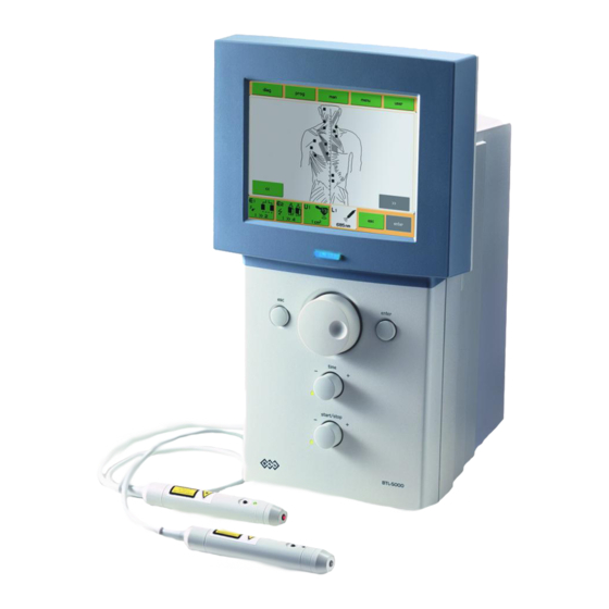
BTL-5000
Series
U S E R ‘ S M A N U A L
v 1 1 2 R K 2 1 / 0 4 / 2 0 0 5 E N
Related Manuals for BTL 5000 Series
Summary of Contents for BTL 5000 Series
-
Page 1
BTL-5000 Series U S E R ’ S M A N U A L v 1 1 2 R K 2 1 / 0 4 / 2 0 0 5 E N… -
Page 2
All of us at BTL wish you every success with your BTL-5000 system. We pride ourselves on being as responsive as possible to our customer’s needs. Your suggestions and comments are always welcome since we believe an ongoing relationship with our customers is critically important to our future product line. -
Page 3: Table Of Contents
Save Therapy and Add It to the Patient Data ………………23 2.10 Interconnection of Units ……………………..26 2.10.1 Interconnection of BTL-5000 Puls (Combi) and Vacuum Unit BTL vac ……….26 2.10.2 Interconnection of BTL-5000 Puls and BTL-5000 Sono ……………..26 2.10.3 Interconnection of BTL-5000 Puls, BTL-5000 Sono and BTL vac …………27 2.10.4…
-
Page 4
Interconnection of Devices………………………48 Manufacturer …………………………49 UNITS CONFIGURATIONS ……………………..50 Table of Configurations of the Combined Devices BTL 5000 Combi …………50 Table of Configurations of the Electrotherapy Devices BTL-5000 Puls…………54 Table of Configurations of the Ultrasound Therapy Devices BTL-5000 Sono ……….55 Table of Configurations of the Laser Therapy Devices BTL-5000 Laser…………55… -
Page 5: General Characteristics
With every BTL unit, you can purchase a cart specially designed for BTL products. Its versatile design allows you to conveniently store and use 1 or 2 physiotherapy units and a vacuum unit. The cart includes a range of accessory trays and baskets.
-
Page 6: Instructions For Use
B T L — 5 0 0 0 S E R I E S U S E R ‘ S M A N U A L I N S T R U C T I O N S F O R U S E 2 .
-
Page 7: Rear View
B T L — 5 0 0 0 S E R I E S U S E R ‘ S M A N U A L R E A R V I E W 1 — 6 patient outputs – for exact configuration see Tab. 2.1 mains switch to switch the power supply on/off socket for connection of the mains cable label showing equipment type and manufacturer and safety precautions and warnings…
-
Page 8
* can be supplied or upgraded with HVT module Notes: connector for connection of electrotherapy accessories (BTL-236-1, BTL vac) to E1 generator connector for connection of electrotherapy accessories (BTL-236-1, BTL vac) to E2 generator connector for connection of electrotherapy accessories (BTL-236-1, BTL vac) to E2 generator… -
Page 9: Unpacking And Assembly
B T L — 5 0 0 0 S E R I E S U S E R ‘ S M A N U A L 2 . 3 U N P A C K I N G A N D A S S E M B L Y Inspect the box for damage and report any damage to carrier and your distributor.
-
Page 10: Operating The Unit
B T L — 5 0 0 0 S E R I E S U S E R ‘ S M A N U A L Connection of accessories: Connect the accessories to the output connectors (1) — (6) on the rear panel according to the Tab. 2.1. The unit will automatically detect their type and display them on the screen.
-
Page 11: Numerical Keyboard
B T L — 5 0 0 0 S E R I E S U S E R ‘ S M A N U A L 2 . 4 . 2 N u m e r i c a l K e y b o a r d In addition to setting numerical value with the select (14) button, you can also use “numerical keyboard”.
-
Page 12: Therapy Setting
B T L — 5 0 0 0 S E R I E S U S E R ‘ S M A N U A L 2 . 5 T H E R A P Y S E T T I N G 2 .
-
Page 13: Welcome Screen And Selection Of Channels, Tabs And Accessories
BTL-236-1 with two electrodes Tab of channel E1 with electrotherapy accessory BTL-236-1 and possibility to apply combined therapy Tab of channel E2 with electrotherapy accessory BTL-236-1 and possibility to apply combined and HVT therapies Tab of selected channel E2 with electrotherapy accessory BTL-236-2.
-
Page 14: Setting Therapy Parameters Via The ‘Diag’ Button
B T L — 5 0 0 0 S E R I E S U S E R ‘ S M A N U A L 2 . 5 . 3 S e t t i n g T h e r a p y P a r a m e t e r s v i a t h e ‘ d i a g ’ B u t t o n Press the diag (8) button to display a list of therapy protocols / diagnoses.
-
Page 15: Setting Therapy Parameters Via The ‘Prog’ Button
Press the prog (9) button to set the required program number. The program numbers generally correspond to the program numbers used in the traditional BTL physiotherapy line. A letter in front of each number corresponds to the type of therapy selected: E – electrotherapy; U – ultrasound; L – laser.
-
Page 16: Setting Therapy Parameters Manually Via The ‘Man’ Button
B T L — 5 0 0 0 S E R I E S U S E R ‘ S M A N U A L 2 . 5 . 5 S e t t i n g T h e r a p y P a r a m e t e r s M a n u a l l y v i a t h e ‘ m a n ‘ B u t t o n Press the man (11) button to select manual setting for therapy.
-
Page 17: Therapy Parameters Screen — Ergonomic, Standard And Expert Mode
B T L — 5 0 0 0 S E R I E S U S E R ‘ S M A N U A L 2 . 5 . 6 T h e r a p y P a r a m e t e r s S c r e e n – E r g o n o m i c , S t a n d a r d a n d E x p e r t M o d e This screen opens after pressing the diag (8) or prog (9) button (see 2.5.1 Therapy Flow Chart) before the start of therapy.
-
Page 18: Course Of Therapy
B T L — 5 0 0 0 S E R I E S U S E R ‘ S M A N U A L 2 . 6 C O U R S E O F T H E R A P Y 2 .
-
Page 19: Running Therapy Screen
B T L — 5 0 0 0 S E R I E S U S E R ‘ S M A N U A L 2 . 6 . 2 R u n n i n g T h e r a p y S c r e e n Therapy description Intensity Time till end of…
-
Page 20: Accessories — Visual Signaling
A c c e s s o r i e s – V i s u a l S i g n a l i n g Accessories BTL-236 (for electrotherapy) and BTL-237 (ultrasound heads) feature blue pilot lights that signal their operating conditions.
-
Page 21: Ultrasound Therapy
2 . 6 . 5 . 2 U l t r a s o u n d T h e r a p y Generation of ultrasound energy by ultrasound head BTL-237 is indicated: • on the screen – by value of intensity •…
-
Page 22: Encyclopaedia
B T L — 5 0 0 0 S E R I E S U S E R ‘ S M A N U A L 2 . 8 E N C Y C L O P A E D I A The encyclopaedia provides information about individual therapies, examples of electrode placement and application areas for ultrasound and laser.
-
Page 23: Therapy Printing And Saving
B T L — 5 0 0 0 S E R I E S U S E R ‘ S M A N U A L 2 . 9 T H E R A P Y P R I N T I N G A N D S A V I N G Pressing the print, save button allows you to make several choices.
-
Page 24
B T L — 5 0 0 0 S E R I E S U S E R ‘ S M A N U A L Set therapy parameters Save therapy select enter Enter name of diagnosis Enter program number Select patient All information is enter… -
Page 25
B T L — 5 0 0 0 S E R I E S U S E R ‘ S M A N U A L A saved therapy will be visible in the: List of diagnoses List of programs and in the list of therapies of the selected patient p a g e 2 5 o f 5 6… -
Page 26: Interconnection Of Units
U n i t B T L v a c Combine any BTL-5000 Puls or Combi unit with the vacuum unit BTL vac to apply electrotherapy currents by means of suction cup electrodes. Adjustable vacuum pressure ensures simple and convenient attachment of patient electrodes, especially on the parts of body hard to reach with classic electrodes.
-
Page 27: Interconnection Of Btl-5000 Puls, Btl-5000 Sono And Btl Vac
‘negative polarity’ in the therapy parameters screen of the electrotherapy unit. To apply electrotherapy only with interconnected units, cancel the choice ‘interconnection with electrotherapy’ on the BTL-5000 Sono screen. The electrotherapy electrodes are automatically connected to the electrotherapy output. 2 . 1 0 . 3…
-
Page 28: Setup And Operation Of Combined Therapy In Single Devices
B T L — 5 0 0 0 S E R I E S U S E R ‘ S M A N U A L 2 . 1 0 . 4 S e t u p a n d O p e r a t i o n o f C o m b i n e d T h e r a p y i n S i n g l e D e v i c e s After checking for correct interconnection of the electrotherapy and ultrasound units, select a diagnosis or program that utilizes combined therapy.
-
Page 29: Menu Button
Make sure the installed accessory is connected directly, not via interface cable and vacuum or BTl-5000 Sono devices. This will help decrease electromagnetic interference that could cause improper reading of memory data.
-
Page 30: Unit Settings
All audio tones can be switched off or modified as required. Units with laser generator — BTL-5000 Laser, BTL-58xx L, BTL-58xx xL — cannot have the audio tone of the running therapy switched off (in compliance with the applicable standards).
-
Page 31: Operation Mode
N e w O p e r a t i o n M o d e Use this option for the first series BTL-5000 units manufactured in 2001 and early in the year 2002. These units have the knobs (17) and (18) marked as time (17) and start / stop (18). For these units, select the option new operation mode = no (after the new version of firmware is loaded).
-
Page 32: File System Formatting
B T L — 5 0 0 0 S E R I E S U S E R ‘ S M A N U A L 3 . 2 . 1 4 . 2 F i l e S y s t e m F o r m a t t i n g Clears all data and programs created by the user.
-
Page 33: User Options Via The «User» Button
B T L — 5 0 0 0 S E R I E S U S E R ‘ S M A N U A L U S E R O P T I O N S V I A T H E “ U S E R ” B U T T O N Pressing the user (13) button opens a screen allowing access to special features of the unit, as well as to data saved by the user.
-
Page 34: User Sequences
B T L — 5 0 0 0 S E R I E S U S E R ‘ S M A N U A L 4 . 2 U S E R S E Q U E N C E S Serves to work with the list of self-designed sequences of therapy programs.
-
Page 35
B T L — 5 0 0 0 S E R I E S U S E R ‘ S M A N U A L Open the therapy parameters screen. In the manual mode select therapy / sequence (or ultrasound sequence or laser sequence). -
Page 36: Parameters Of Sections In Sequence
B T L — 5 0 0 0 S E R I E S U S E R ‘ S M A N U A L 4 . 2 . 1 . 1 P a r a m e t e r s o f S e c t i o n s i n S e q u e n c e A sequence consists of a few currents/programs that are called sections.
-
Page 37: User Diagnoses/Programs
B T L — 5 0 0 0 S E R I E S U S E R ‘ S M A N U A L 4 . 3 U S E R D I A G N O S E S / P R O G R A M S Use this feature to run user designed therapies and edit and delete their parameters, names and therapy comments.
-
Page 38: Accessories
A C C E S S O R I E S F O R U L T R A S O U N D T H E R A P Y user’s guide for ultrasound therapy holder for ultrasound head ultrasound head BTL-237-1-13 for 1 and 3MHz, ERA 0.7 cm ultrasound head BTL-237-4-13 for 1 and 3MHz, ERA 3.24 cm ultrasound gel 235ml, 5l, 10l interface cable between BTL-56xx Puls and BTL-57xx Sono, type PVAC.056…
-
Page 39: Maintenance And Safety Instructions
B T L — 5 0 0 0 S E R I E S U S E R ‘ S M A N U A L M A I N T E N A N C E A N D S A F E T Y I N S T R U C T I O N S All maintenance and repairs must be carried out by authorized personnel only.
-
Page 40: Safety
Always follow your local and national electrical, safety and healthy standards when using this equipment. Call your distributor for advice. • The device does not have any user-servicing parts. Do not remove any covers. Always have the unit repaired by BTL Service Department. p a g e 4 0 o f 5 6…
-
Page 41
• For therapy use only the BTL ultrasound gel; the head is not tested for other gels or oils and use of them could damage the head. If you still want to use other gels, we recommend them to be only water-based gels. -
Page 42: Useful Addresses
6 . 2 U S E F U L A D D R E S S E S The product is manufactured in accordance with the EU Medical Devices Directive by : BTL Industries Ltd. Suite 401 Albany House 324-326 Regents Street…
-
Page 43: Contraindications
B T L — 5 0 0 0 S E R I E S U S E R ‘ S M A N U A L 6 . 4 C O N T R A I N D I C A T I O N S The list of contraindications gives the cases when the manufacturer does not recommend to apply the selected therapy.
-
Page 44: Technical Parameters
0 and I Power switch on the front panel, labelled on off Internal chemical sources Type of batteries lithium CR2032 (replacement by BTL Service Department) Design Weight – device only max. 5 kg Weight –…
-
Page 45: Basic Parameters Of Ultrasound Generator
B T L — 5 0 0 0 S E R I E S U S E R ‘ S M A N U A L Output voltage — HVT max. 390 V (maximum instantaneous value) *maximum value for some currents is limited according to IEC 601-2-10 Tolerance of output amplitude ±…
-
Page 46: Technical Parameters Of Ultrasound Heads
U S E R ‘ S M A N U A L Adjustable values Frequency*** 0 – 5000 Hz, (0 – 10000 Hz for C variant) with laser probe BTL-448 0 – 500 Hz with laser cluster BTL-445 accuracy of frequency ±…
-
Page 47: Technical Parameters Of Laser Clusters
B T L — 5 0 0 0 S E R I E S U S E R ‘ S M A N U A L Laser probes with infrared (invisible) radiation: Type: BTL-448-05IC BTL-448-10IC BTL-448-20IC BTL-448-30IC Output power: 50 mW ± 20 % 100 mW ±…
-
Page 48: Applicable Standards
I N T E R C O N N E C T I O N O F D E V I C E S BTL-5000 Puls can be interconnected with: BTL vac, BTL-5000 Sono, BTL-12, BTL-07p, BTL-4000 Sono BTL-5000 Combi can be interconnected with:…
-
Page 49: Manufacturer
The contents of this document is provided «as is». Except as required by applicable law, no warranties of any kind, either expressed or implied, are made in relation to the accuracy, reliability or contents of this document. BTL Industries Limited reserves the right to revise this document or withdraw it at any time without prior notice.
-
Page 50: Units Configurations
B T L — 5 0 0 0 S E R I E S U S E R ‘ S M A N U A L U N I T S C O N F I G U R A T I O N S 8 .
-
Page 51
B T L — 5 0 0 0 S E R I E S U S E R ‘ S M A N U A L Type: 5820SL 5825SL 5820L 5825L 5830L 5835L 5840S 5840SL 5840L 5860L Number of therapies Electrotherapy Ultrasound therapy Laser therapy… -
Page 52
B T L — 5 0 0 0 S E R I E S U S E R ‘ S M A N U A L Type: 5800SLC 5810SC 5810S2C 5810SLC 5810LC 5810L2C 5820SC 5825SC Number of therapies Electrotherapy Ultrasound therapy Laser therapy Patient cardfile (positions) min. -
Page 53
B T L — 5 0 0 0 S E R I E S U S E R ‘ S M A N U A L Type: 5820SLC 5825SLC 5820LC 5825LC 5830LC 5835LC 5840SC 5840SLC 5840LC 5860LC Number of therapies Electrotherapy Ultrasound therapy Laser therapy… -
Page 54: Table Of Configurations Of The Electrotherapy Devices Btl-5000 Puls
B T L — 5 0 0 0 S E R I E S U S E R ‘ S M A N U A L 8 . 2 T A B L E O F C O N F I G U R A T I O N S O F T H E E L E C T R O T H E R A P Y D E V I C E S B T L — 5 0 0 0 P U L S Type: 5610…
-
Page 55: Table Of Configurations Of The Ultrasound Therapy Devices Btl-5000 Sono
50 min. 150 min. 150 Step of setting of values standard standard fine fine Encyclopaedia Preset diagnoses Preset programs Interconnection with BTL-5000 Puls Interconnection with PC optional optional optional optional Print optional optional optional optional Language versions Sound schemes…
-
Page 56
B T L — 5 0 0 0 S E R I E S U S E R ‘ S M A N U A L p a g e 5 6 o f 5 6…

BTL-4000
Magnetotherapy
U S E R ’ S G U I D E
110DA03/03/2008EN

|
CONTENTS |
||
|
1. |
M AGNETOTHER APY ………………………………………………………………………….. |
. 4 |
|
2. |
MAGNETOTHERAPY – PHYSICAL BACKGROUND ………………………………………. |
5 |
|
2.1 |
Magnetic Field ……………………………………………………………………………………………………………………… |
5 |
|
2.1.1 |
Stationary Magnetic Field………………………………………………………………………………………………….. |
6 |
|
2.1.2 |
Alternating Magnetic Field…………………………………………………………………………………………………. |
6 |
|
2.1.3 |
Pulse Magnetic Field………………………………………………………………………………………………………… |
6 |
|
2.2 |
FMF Technology…………………………………………………………………………………………………………………… |
7 |
|
2.3 |
Magnetic Field Units ……………………………………………………………………………………………………………… |
8 |
|
3. |
THERAPEUTIC EFFECTS OF MAGNETOTHERAPY …………………………………….. |
10 |
|
3.1 |
Analgesic Effect………………………………………………………………………………………………………………….. |
10 |
|
3.2 |
Antiphlogistic Effect …………………………………………………………………………………………………………….. |
10 |
|
3.3 |
Trophic Effect …………………………………………………………………………………………………………………….. |
11 |
|
3.4 |
Myorelaxation and Spasmolytic Effect ……………………………………………………………………………………. |
11 |
|
3.5 |
Vasodilatation Effect ……………………………………………………………………………………………………………. |
11 |
|
3.6 |
Antiedematous Effect…………………………………………………………………………………………………………… |
11 |
|
4. |
RECOMMENDED DOSAGE OF MAGNETOTHERAPY …………………………………… |
12 |
|
5. |
BIBLIOGRAPHY ……………………………………………………………………………….. |
13 |
|
6. |
SETTING AND CONTROL OF MAGNETOTHERAPY – TECHNICAL PARAMETERS . 16 |
|
|
6.1 |
Magnetic Field Intensity ……………………………………………………………………………………………………….. |
16 |
|
6.2 |
Therapy DURATION……………………………………………………………………………………………………………. |
16 |
|
6.3 |
Physiological Effects……………………………………………………………………………………………………………. |
16 |
|
6.4 |
Selection of Therapy……………………………………………………………………………………………………………. |
16 |
|
6.4.1 |
Magnetic Pulses…………………………………………………………………………………………………………….. |
17 |
|
6.4.2 |
Series of Magnetic Pulses……………………………………………………………………………………………….. |
17 |
|
6.4.3 |
Continuous Magnetic Field………………………………………………………………………………………………. |
18 |
|
6.5 |
Pulse Shape ………………………………………………………………………………………………………………………. |
19 |
|
6.5.1 |
Rectangular Pulses ………………………………………………………………………………………………………… |
19 |
|
6.5.2 |
Rectangular Protracted Pulses ………………………………………………………………………………………… |
20 |
|
6.5.3 |
Exponential Pulses…………………………………………………………………………………………………………. |
21 |
|
6.5.4 |
Sinusoidal Pulses…………………………………………………………………………………………………………… |
22 |
|
6.5.5 |
Triangular Pulses …………………………………………………………………………………………………………… |
22 |
|
6.6 |
Modulation …………………………………………………………………………………………………………………………. |
23 |
|
6.6.1 |
Random Frequency………………………………………………………………………………………………………… |
23 |
|
6.6.2 |
Burst…………………………………………………………………………………………………………………………….. |
23 |
|
6.6.3 |
Sine Surges ………………………………………………………………………………………………………………….. |
23 |
|
6.6.4 |
Trapezoid Surges…………………………………………………………………………………………………………… |
24 |
|
6.6.5 |
Symmetric Surges………………………………………………………………………………………………………….. |
24 |
|
6.7 |
Test of Connected Applicator ……………………………………………………………………………………………….. |
25 |
|
7. |
APPLICATORS ………………………………………………………………………………… |
26 |
|
7.1 |
“Disc» Applicator …………………………………………………………………………………………………………………. |
26 |
|
7.1.1 |
Technical Parameters …………………………………………………………………………………………………….. |
27 |
|
7.1.2 |
Shape of the Magnetic Field of the Applicator…………………………………………………………………….. |
27 |
|
7.2 |
“Double Disc» Applicator ………………………………………………………………………………………………………. |
28 |
|
7.2.1 |
Technical Parameters …………………………………………………………………………………………………….. |
28 |
|
7.2.2 |
Shape of the Magnetic Field of the Applicator…………………………………………………………………….. |
29 |
PAGE 2 OF 35

|
7.3 |
“Multi Disc» Applicator………………………………………………………………………………………………………….. |
30 |
|
7.3.1 |
Technical Parameters …………………………………………………………………………………………………….. |
30 |
|
7.3.2 |
Shape of the Magnetic Field of the Applicator…………………………………………………………………….. |
31 |
|
7.4 |
“Solenoid 30” Applicator ………………………………………………………………………………………………………. |
32 |
|
7.4.1 |
Technical Parameters …………………………………………………………………………………………………….. |
32 |
|
7.4.2 |
Shape of the Magnetic Field of the Applicator…………………………………………………………………….. |
32 |
|
7.5 |
“Solenoid 60” Applicator ………………………………………………………………………………………………………. |
33 |
|
7.5.1 |
Technical Parameters …………………………………………………………………………………………………….. |
33 |
|
7.5.2 |
Shape of the Magnetic Field of the Applicator…………………………………………………………………….. |
33 |
|
7.6 |
“Linear» Applicator ………………………………………………………………………………………………………………. |
34 |
|
7.6.1 |
Technical Parameters …………………………………………………………………………………………………….. |
34 |
|
7.6.2 |
Shape of the Magnetic Field of the Applicator…………………………………………………………………….. |
34 |
|
7.7 |
“Solenoid 70” Applicator ………………………………………………………………………………………………………. |
35 |
|
7.7.1 |
Technical Parameters …………………………………………………………………………………………………….. |
35 |
|
7.7.2 |
Shape of the Magnetic Field of the Applicator…………………………………………………………………….. |
35 |
PAGE 3 OF 35

1. MAGNETOTHERAPY
Magnetotherapy is one of the basic physiotherapy procedures. Its basic form — application of a static magnetic field, i.e. a permanent magnet — has been used since time immemorial as one of the natural healing sources. However, only the coming of electronics and powerful switching elements enabled the rapid development of lowfrequency pulse magnet therapy, the effects of which are several times greater than those of the static magnetic field. Recently performed studies imply that therapy performed by means of pulse electromagnetic field is up to 100 times more effective than the application of a stationary magnetic field. That is why pulse magnetotherapy is becoming one of the most widespread physiotherapy methods nowadays. In some conditions (e.g. chronic pains in degenerative articular diseases) this method has proven successful as therapy withlong-lasting therapeutic effect even when other therapy methods failed.
Pulse magnetotherapy can be very effective in case of correct indication and application. It can also be recommended for use in combination with other therapy methods, such as pharmacotherapy, the effects of which are usually supported by magnetotherapy. That is why magnetotherapy should neither be left out in case of a comprehensive approach to treatment, nor given preference as monotherapy.
The latest findings about the physiological response of the body to the electromagnetic field imply the following effects of magnetotherapy:
•analgesic effect,
•antiedematous effect,
•antiphlogistic effect,
•trophic effect (acceleration of healing and growth),
•myorelaxation and spasmolytic effect,
•vasodilatation effect.
The following chapters contain a brief explanation of the physical background of magnetotherapy and the physiological mechanisms of its effect with the emphasis on application in individual fields of medicine.
The Encyclopaedia, which is a separate attachment to this User’s Guide, contains a list of recommended parameters of magnetotherapy in selected diagnoses.
The design of this device utilizes the experience acquired during the development, manufacturing and long-standing clinical operation of the BTL-09 device and state-of-the-art devices in the BTL-4000 and BTL-5000 series. During the design of new magnetic applicators for this device, there was developed a brand new technology – so-called “FMF” (“Focused Magnetic Field”) technology. Thus we managed to increase the electromagnetic field intensity on the patient’s side and significantly reduce the electromagnetic field intensity on the applicator’s side, turned away from the patient. Colloquially put, the magnetic field was moved from the improper side to the side where it is desired.
Thanks to these construction elements and thanks to state-of-the-art sources based on the principle of electronic switching elements, we have managed to reduce the power consumption significantly while preserving the same electromagnetic field intensities.
Note
The authors of this User’s Guide are aware that such a small space is not sufficient for a detailed description of the entire magnetotherapy issue. They therefore had to make some generalizations and simplifications resulting from the limited scope of this text. More details can be found in the available literature (see the chapter
Bibliography).
MAGNETOTHERAPY | PAGE 4 OF 35

2. MAGNETOTHERAPY – PHYSICAL BACKGROUND
2.1MAGNETIC FIELD
The magnetic field is an integral part of the electromagnetic field, which consists of electrical and magnetic components. Both components of the electromagnetic field are mutually closely connected and cannot exist without each other, except in the following two special cases:
•electrostatic field, in which the magnetic component of the field is zero, and
•stationary magnetic field, in which the electrical component is zero.
Owing to the used frequencies up to 150 Hz and owing to the design of the BTL applicators, the magnetic component of the field predominates over the electrical. In short we will hereinafter call the field by the commonly used term “magnetic field”.
The presence of a magnetic field is sensed primarily through its force effects, by which it affects magnetically conductive things, moving charges and conductors with electric current flowing through them. The force effects are not very important for our theory, because biological objects are diamagnetic. However, it is necessary to take these force effects into account in case of metal implants, especially those which are fixed in soft tissues and are not made of antimagnetic materials.
Another interaction between the magnetic field and matter occurs at the moment when matter is exposed to the magnetic field. At that moment, individual free molecules are orientated in such a way as to minimize the energy inside the field. In case of biological objects, these forces act against the bonds between atoms, molecules and ions in the tissues, which consequently also influence the cellular processes.
The effects important for physiotherapy are based on electrodynamic induction, discovered by the physicist M. Faraday in the 19th century. In practice, if you move an electric conductor in a magnetic field, voltage appears on it. If you make a closed loop of the moving conductor, electric current will flow through it. As Faraday discovered, this phenomenon also works the other way around – if the magnetic field moves or changes in the course of time (instead of the conductor), a similar effect occurs. These discoveries were only a short remove from the application of alternating magnetic fields in therapy.
In case of living organisms, the moving charges (the conductor moving in the magnetic field) are represented by the circulating body fluids (blood, lymph). In case of exposure to an alternating magnetic field, it refers to its individual more electrically conductive parts — the vascular bed (including circulating fluids), peripheral nerves, CNS neural paths and, last but not least, also individual ions and charges on cellular membranes.
MAGNETOTHERAPY – PHYSICAL BACKGROUND | PAGE 5 OF 35
2.1.1STATIONARY MAGNETIC FIELD
A stationary magnetic field arises around permanent magnets but also around moving electric charges which move at a constant speed (direct current).
Electric charge may be carried e.g. by ions (electric current flowing in liquids) and electrons (electric current flowing in conductors). In the latter case, a magnetic field similar to that around a permanent magnet arises around the electric conductor with constant direct electric current flowing through it.
2.1.2ALTERNATING MAGNETIC FIELD
The time behaviour of this field is usually derived from the sinusoidal mains voltage. In common practice, devices most often generate fields of a frequency of 50 Hz and the sinusoidal waveform. The magnetic fields of these devices change their polarity in the course of time.
These fields, even though with much lower intensity, exist in the surroundings of each electrical conductor, transformer and motor supplied from the AC mains.
2.1.3PULSE MAGNETIC FIELD
This field is characterized by fast changes of field; individual pulses are close to rectangular pulses, their edges are very steep. That is why in a pulse magnetic field the electrical component is higher and is permanently present beside the magnetic component. Some studies, which deal with the comparison of individual magnetic field types, point out the very high efficiency of the pulse magnetic field in comparison with the stationary magnetic field. Therefore, the question arises whether the positive results of the pulse magnetic field are not caused by the more intensive electrical component of the field.
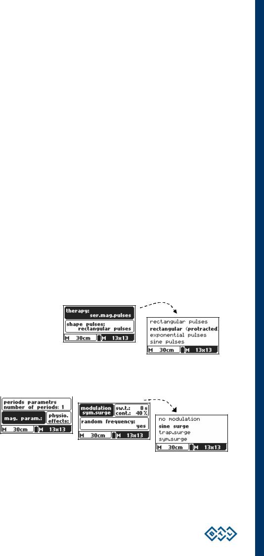
Of all the possible pulse types, the BTL – 4000 Topline device has been equipped with the following ones. These pulses cover the entire spectrum of required applications, from acute to chronic states.
•Device Options
The device can be set to generate the following pulse types:
• rectangular pulses,
•rectangular protracted pulses,
•exponential pulses,
•sinusoidal pulses,
•triangular pulses and
•continuous magnetic field.
All the above listed magnetic field waveforms can be further modulated and the following surges of basic pulses can be created: 
• trapezoid surges,
•sine surges,
•symmetrical surges.
It is also possible to create groups of magnetic pulses — so called bursts.
The option of random sweep of the basic selected frequency is available, too.
All these parameters can be set in the well-arranged manual mode. Preset programs and recommended diagnoses are available, too.
MAGNETOTHERAPY – PHYSICAL BACKGROUND | PAGE 6 OF 35

2.2 FMF TECHNOLOGY
FMF = Focused Magnetic Field
In dependence on their spatial distribution, magnetic fields are divided into uniform and non-uniform. The uniform field has the same intensity and the same direction in all points of space.
The applicators were designed using state-of the-art ferromagnetic and magnetic materials which enable highly effective magnetic concentration systems to be assembled. These elements focus the electromagnetic field onto the desired space towards the treated body part. Therefore, the magnetic field of the BTL applicator is intentionally non-uniform and focused.
|
Standard Magnetic Applicator |
FMF Technology Applicator of DISC Type |
The sides of the applicator are identified as the patient side, from which the magnetic field is emitted to a higher extent, and the operator side, where the field intensities are several times lower.
blue indicator light
|
Patient / Application |
Side turned away from the patient |
|
Side of the Applicator |
(operator side) |
The side is marked with a pictograph of a “patient in the magnetic field”. The intensities on this side of the applicator are much higher than those on the operator’s side. During operation of the device, the operator should not touch this side of the applicator.
The side marked with the BTL logo. It is also equipped with a blue indicator lamp which indicates operation of the applicator (continuous light, fast blinking) and its readiness for operation (slow blinking).
MAGNETOTHERAPY – PHYSICAL BACKGROUND | PAGE 7 OF 35

Example of possible use of the magnetic applicator with FMF technology:
The magnetic field of the solenoid type applicators is focused inward:
|
Standard applicator |
and its |
FMF technology applicator |
|
— magnetic field |
— focused magnetic field |
2.3MAGNETIC FIELD UNITS
The BTL-4000, BTL-4000 Topline and BTL-5000 devices use for magnetic field induction (B) the unit according to the SI international unit system – Tesla (T) or its one thousandth — millitesla (mT).
Owing to the fact that the formerly used unit Gauss (G) has the following relation to millitesla:
1mT = 10 G, the display shows the converted value in mT/10.
Then, 1mT/10 = 1G.
Other magnetic field units:
Then the unit of magnetic field intensity is ampere per meter (A/m).
An older unit of intensity is Oersted (Oe).
The relation between these two units is: 1 Oe = 79.577 A/m.
The relation between magnetic induction and magnetic intensity is the following:
B = µr . µo . H
MAGNETOTHERAPY – PHYSICAL BACKGROUND | PAGE 8 OF 35

where: B is the magnetic induction
H is the magnetic intensity
µo is the permeability of a vacuum, which equals 1.2566 . 10-6
µr is the relative permeability of the environment, which expresses the magnetic properties of the environment
•for a vacuum it equals 1
•for magnetically conductive materials, the values are much higher than 1 (e.g. for steel, the values range from 100 to 5800)
•for air, the value is similar as for a vacuum, i.e. approximately 1 (1.00000038 to be accurate)
•biological tissues from this view can be compared to water, for which the value equals 0.999991
It can be calculated that for biological tissues a magnetic field induction of 1mT corresponds to a magnetic field intensity of 795.8 A/m.
MAGNETOTHERAPY – PHYSICAL BACKGROUND | PAGE 9 OF 35

3. THERAPEUTIC EFFECTS OF MAGNETOTHERAPY
Magnetotherapy is one of the most commonly used physiotherapy procedures. This method has proved successful in some diseases as therapy with long-lasting therapeutic effect (e.g. in chronic pains of vertebrogenous aetiology or in degenerative joint diseases) even when other therapy methods have failed. However, it is necessary to consider that, like every therapeutic procedure, magnetotherapy also has a certain failure rate.
It has been proved that for the treatment of patients in acute stages it is better to use a static magnetic field at the beginning; in chronic diseases it is better to use pulse magnetotherapy. Application of magnetotherapy must always be based on a thorough medical history and detailed examination of the patient.
It is suitable to take into account that the natural magnetic field of the Earth equals approximately 0.04 – 0.05 mT (0.4 – 0.5 Gauss). The BTL-4000, BTL-4000 Topline and BTL-5000 devices work with magnetic fields, the intensity of which may be up to 1000 times higher. Therefore, the application requires particular caution, also with respect to the fact that man has no specific receptors for a magnetic field and therefore does not perceive it directly – unlike e.g. an electric current.
The latest findings about the physiological response of the body to the electromagnetic field imply the following effects of magnetotherapy:
•analgesic effect,
•antiphlogistic effect,
•trophic effect (acceleration of healing and growth),
•myorelaxation and spasmolytic effect,
•vasodilatation effect,
•antiedematous effect.
3.1ANALGESIC EFFECT
The analgesic effect of magnetotherapy applies in most algesic states of muscular as well as articular aetiology. A detailed description of this effect is quite complicated; its physiological effects have been specified in recent years. According to these findings, the analgesic effect of magnetotherapy is accounted for by the increased secretion of endogenous opioids caused by the myorelaxation, antiphlogistic and antiedematous effect and maybe also the impact on presinaptic inhibition of nociceptive signals at the level of the medullary dorsal horns.
The treatment should be combined with aimed pharmacotherapy, manual treatment and relaxation therapy, at least in the initial stage.
3.2ANTIPHLOGISTIC EFFECT
This effect has not been convincingly explained so far, but recent studies agree on the following principle:
The antiphlogistic effect is induced by increased phagocytosis of neutrophils and the increased production of hyperoxide. This is followed by the induction of hyperoxide dismutase bound to endothelium, which all probably leads to a higher concentration of hydrogen peroxide in the exposed area. Owing to the fast that hyperoxide inhibits the activity of catalase, the hydrogen peroxide is not degraded and thus is able to destroy leucotriens, some of the strongest activators of phagocytosis.
THERAPEUTIC EFFECTS OF MAGNETOTHERAPY | PAGE 10 OF 35
![]()
This mechanism also explains the initial controversial action of the magnetic field in sterile inflammations as well as in microbially induced inflammations. This effect also accounts for temporary impairment of rheumatic conditions during the first two or three exposures, when the inflammatory symptoms are intensified by increasingly produced hyperoxide.
Simultaneous medication and physical therapy is necessary; the patient must be monitored during the therapy and in case of longer negative reaction, the therapy must be stopped.
3.3TROPHIC EFFECT
The magnetic field accelerates healing of the skeleton and soft tissues. It is caused by better blood circulation in the exposed area and by the irritation of cytoplasmatic membranes. This activates the metabolic chain, the key point of which is a change in the cAMP/cGMP ratio.
The acceleration of healing, especially of the skeleton, is described in detail in the literature (Chvojka, 1993, 2000).
3.4MYORELAXATION AND SPASMOLYTIC EFFECT
Increased blood circulation in the area improves the washing away of acidic metabolites which cause painful irritation. In the muscles exposed to the magnetic field there also proceeds increased activity of LDH (lactate dehydrogenase) and efflux of the Ca2+ ion from muscle cells.
3.5VASODILATATION EFFECT
This effect is caused by the efflux of Ca2+ ions, which causes relaxation of the tonus of the vascular musculature and precapillary sphincters. Probably the n. vagus is also directly influenced and the increased metabolic activity of cells in the exposed area results in the creation of EDRF and prostacyclins.
3.6ANTIEDEMATOUS EFFECT
This effect results from the two above-described effects — the antiphlogistic effect of the magnet and acceleration of healing and improved blood circulation.
THERAPEUTIC EFFECTS OF MAGNETOTHERAPY | PAGE 11 OF 35
 Loading…
В наличии документация на медицинское оборудование фирмы BTL (в т.ч. на русском языке):
Modification: 30 August 2023
Инструкция пользователя (User manual) на BTL VAC [BTL] Терапия
Инструкция по эксплуатации (Operation (Instruction) manual) на BTL-06 [BTL] Терапия
Руководство пользователя (Users guide) на BTL-07P [BTL] Терапия
![Руководство пользователя Users guide на BTL-07P [BTL]](https://medtechnic.net.ua/img_d/9000/9386.jpg "Руководство пользователя Users guide на BTL-07P [BTL]")
Руководство пользователя (Users guide) на BTL-08 [BTL] Диагностика-ЭКГ
![Руководство пользователя Users guide на BTL-08 [BTL]](https://medtechnic.net.ua/img_d/0000/660.jpg "Руководство пользователя Users guide на BTL-08 [BTL]")
Сервисная инструкция (Service manual) на BTL-08 ECG-Spiro [BTL] Диагностика-ЭКГ
![Сервисная инструкция Service manual на BTL-08 ECG-Spiro [BTL]](https://medtechnic.net.ua/img_d/9000/9510.jpg "Сервисная инструкция Service manual на BTL-08 ECG-Spiro [BTL]")
Сервисная инструкция (Service manual) на BTL-08 Holter [BTL] Диагностика-ЭКГ
![Сервисная инструкция Service manual на BTL-08 Holter [BTL]](https://medtechnic.net.ua/img_d/9000/9509.jpg "Сервисная инструкция Service manual на BTL-08 Holter [BTL]")
Сервисная инструкция (Service manual) на BTL-08 SD ECG [BTL] Диагностика-ЭКГ
![Сервисная инструкция Service manual на BTL-08 SD ECG [BTL]](https://medtechnic.net.ua/img_d/9000/9511.jpg "Сервисная инструкция Service manual на BTL-08 SD ECG [BTL]")
Сервисная инструкция (Service manual) на BTL-20 [BTL] Терапия
![Сервисная инструкция Service manual на BTL-20 [BTL]](https://medtechnic.net.ua/img_d/9000/9503.jpg "Сервисная инструкция Service manual на BTL-20 [BTL]")
Сервисная инструкция (Service manual) на BTL-21 [BTL] Терапия
![Сервисная инструкция Service manual на BTL-21 [BTL]](https://medtechnic.net.ua/img_d/9000/9508.jpg "Сервисная инструкция Service manual на BTL-21 [BTL]")
Инструкция пользователя (User manual) на BTL-4000 Series [BTL] Терапия
Методические материалы (Methodical materials) на BTL-4000/5000 Электротерапия Список диагнозов [BTL] Терапия
![Методические материалы Methodical materials на BTL-4000/5000 Электротерапия Список диагнозов [BTL]](https://medtechnic.net.ua/img_d/8000/8529.jpg "Методические материалы Methodical materials на BTL-4000/5000 Электротерапия Список диагнозов [BTL]")
Инструкция пользователя (User manual) на BTL-5000 Series [BTL] Терапия
Инструкция пользователя (User manual) на BTL-5000 Shocwave Series [BTL] Терапия
Сервисная инструкция (Service manual) на BTL-5000 SWT Series [BTL] Терапия
Сервисная инструкция (Service manual) на BTL-6000 Shortwave [BTL] Терапия
![Сервисная инструкция Service manual на BTL-6000 Shortwave [BTL]](https://medtechnic.net.ua/img_d/9000/9512.jpg "Сервисная инструкция Service manual на BTL-6000 Shortwave [BTL]")
Руководство пользователя (Users guide) на BTL-6000 SWT Series [BTL] Терапия
![Руководство пользователя Users guide на BTL-6000 SWT Series [BTL]](https://medtechnic.net.ua/img_d/8000/8416.jpg "Руководство пользователя Users guide на BTL-6000 SWT Series [BTL]")
Архив технической документации медицинского оборудования © 2006 … 2023
- Manuals
- Brands
- BTL Manuals
- Medical Equipment
- 6000 SWT TOPLINE
- User manual
-
Contents
-
Table of Contents
-
Bookmarks
Quick Links
BTL-6000 SWT
TOPLINE
USER’S MANUAL
v100AS08/01/2010EN
GENERAL CHARACTERISTICS OF THE DEVICE | PAGE 1 OF 38
Related Manuals for BTL 6000 SWT TOPLINE
Summary of Contents for BTL 6000 SWT TOPLINE
- Page 1
BTL-6000 SWT TOPLINE USER’S MANUAL v100AS08/01/2010EN GENERAL CHARACTERISTICS OF THE DEVICE | PAGE 1 OF 38… - Page 2
BEFORE YOU START Dear Customer, Thank you for purchasing BTL technology. All of us at BTL wish you every success with your system. We pride ourselves on being as responsive as possible to our customers’ needs. Your suggestions and comments are always welcome since we believe an ongoing relationship with our customers is critically important to our future product line. -
Page 3: Table Of Contents
Possible side Effects of Shockwave Treatment……………………7 Indications for Shockwave Treatment ……………………..8 Contra-indications for Shockwave Treatment……………………8 INSTRUCTIONS FOR OPERATION……………………….9 The Front Panel of the BTL-6000 SWT Topline ……………………9 Applicator for BTL-6000 SWT Topline ……………………..9 The Rear Panel of the BTL-6000 SWT Topline…………………….10 Assembly and Set-Up………………………….11 Basic Displays and Operating of the Device ……………………12…
- Page 4
2.11.3.8 Operation Mode …………………………23 2.11.3.9 Touch Panel Calibration……………………….23 2.11.3.10 User Options…………………………..23 2.11.3.11 Setting of HW Key …………………………23 2.11.3.12 Unit Information …………………………23 2.11.3.13 Unlock Code …………………………..23 2.11.3.14 Service Functions …………………………24 2.11.4 Specific Settings …………………………..24 2.11.4.1 Applicator Button Mode……………………….24 2.11.4.2 Applicator Kit Replacement Wizard …………………….24 LIST OF STANDARD AND OPTIONAL ACCESSORIES ………………..25 MAINTENANCE AND SAFETY INSTRUCTIONS……………………26 4.1.1… -
Page 5: General Characteristics Of The Device
A time-saving feature of the BTL-6000 SWT Topline is the predefined programs stored in the memory of the main unit. Based on detailed research and practical use of the device, the well-organized predefined programs will provide recommendations for the treatment of various conditions.
-
Page 6: Shockwave And Its Character
Several types of generators have been developed for shockwave therapy, each producing shockwaves with varied characteristics. Each type of generation method induces shockwaves with different time progressions and spatial arrangements. The BTL-6000 SWT Topline uses the ballistic principle of shockwave generation. 1.3.1 BALLISTIC PRINCIPLE OF SHOCKWAVE GENERATION A pressure wave is formed via a projectile by using accelerated compressed air.
-
Page 7: Biological Effects Of Shockwave Treatment
1.4 BIOLOGICAL EFFECTS OF SHOCKWAVE TREATMENT The effects of the shockwaves mainly occur at sites where there is a change in impedance, such as the bone-soft tissue interface. There is an improvement in the regeneration and repair of tissues in the following areas and the achievement of the following effects: •…
-
Page 8: Indications For Shockwave Treatment
1.7 INDICATIONS FOR SHOCKWAVE TREATMENT • Plantar Fasciitis • Achillodynia/Achillobursitis • Inflammations and calcification of shoulder joint tendons. • Pain in the groin area. • Epicondylitis (Tennis and Golf Elbow) • Apex Patellae Syndrome and Tibial Stress Syndrome. • Pain in the hip area and/or the iliotibial tract. •…
-
Page 9: Instructions For Operation
2 INSTRUCTIONS FOR OPERATION THE FRONT PANEL OF THE BTL-6000 SWT TOPLINE 10 3 10 4 10 5 10 2 touch screen select knob (to select individual parameters) enter key esc key start / stop key (to start and stop therapy) ON/OFF switch (back lit, in blue, when the control unit is ‘’on’’…
-
Page 10: The Rear Panel Of The Btl-6000 Swt Topline
THE REAR PANEL OF THE BTL-6000 SWT TOPLINE connector for shockwave applicator control unit mains fuse connector for power cable power on/off switch vessel for collecting condensed water type label – contains type of the device, manufacturer and safety and warning signs…
-
Page 11: Assembly And Set-Up
Do not place the device close to appliances producing strong electromagnetic, electric or magnetic field (diathermy, X-rays, etc.), otherwise it could be undesirably influenced. In the event of any questions, please contact an authorized service of BTL devices. Procedure: First connect the device in mains by means of the supplied power supply adapter, which you will connect to the connector on the rear panel of the device and to a 100 V or 240 V mains socket.
-
Page 12: Basic Displays And Operating Of The Device
BASIC DISPLAYS AND OPERATING OF THE DEVICE 2.5.1 INITIAL SCREEN AND TYPES OF TABS The initial screen after the switch-on of the device contains the tab displaying information about the connected accessories. Examples of information shown on the tabs: Indicates that no accessories are connected Indicates that the applicator is connected and shockwave therapy can be applied.
-
Page 13: Numeric Keypad
2.5.3 NUMERIC KEYPAD In addition to setting the numerical values with the select knob on all the screens, the ”numeric keypad» can be use for the faster setting of values. This is the icon for the opening of the numeric keyboard window: Press the numeric keypad button to display the window with the numeric keypad for the parameter with the “pressed”…
-
Page 14: Setting Therapy Parameters Manually (User Setup) Via The ‘Man’ Button
2.6.3 SETTING THERAPY PARAMETERS MANUALLY (USER SETUP) VIA THE ‘MAN’ BUTTON The therapy parameters screen for the user (manual) setting will be displayed by pressing the man button. All specifications of the therapy can be set and possibly saved as a user program or a diagnosis. Pressing of individual buttons will open an individual menu and pop-up boxes for the settings.
-
Page 15: Setting Therapy Intensity
The endless therapy option allows for an infinite number of shocks, that can be applied from the start of the therapy. The end of therapy is not limited to the number of shocks. 2.6.5 SETTING THERAPY INTENSITY The intensity (power) of the shockwave therapy can be set on the therapy parameters screen, even during the course of therapy.
-
Page 16: Therapy Parameters Screen — Ergonomic, Standard And Expert Mode
2.6.6 THERAPY PARAMETERS SCREEN – ERGONOMIC, STANDARD AND EXPERT MODE This screen always appears before the start of therapy when the diag or prog buttons are pressed (see Diagram of the therapy setting process). If only the most important therapy parameters are shown, then the ergonomic operation mode was selected.
-
Page 17: Running Therapy Screen
2.7.2 RUNNING THERAPY SCREEN Name of selected therapy / program and the set parameters Set frequency Number of applied shocks Set number of shocks Set intensity Number of remaining shocks Icon and name of connected accessories Time of applied therapy Symbolic description of generated output 2.7.3…
- Page 18
Examples of how to hold the shockwave applicator These examples illustrate the application of shockwaves in different areas and several of ways of holding the applicator. Painful shoulder Trigger-points Tibial Edge Syndrome Calcar Calcanei (Plantar Fasciitis) Epicondylitis Achillodynia Patellar Tendinopathy (Jumper’s Knee) Trigger points INSTRUCTIONS FOR OPERATION | PAGE 18 OF 38… -
Page 19: Saving Therapy
SAVING THERAPY A particular operation can selected after pressing the “save” button. Depending on which operation is selected, a chart with the appropriate data will be shown. An example of the procedure is displayed on the following screens. It is always possible to save the therapy after setting its parameters, for example from the screen of therapy parameters – see the chapter Therapy parameters screen.
-
Page 20: Clients
2.10.1 CLIENTS This feature allows the entering, editing and deleting of information about clients. A particular therapy can be assigned to each client. 2.10.2 USER DIAGNOSES/PROGRAMS This feature makes it possible to start the user therapies, to adjust their parameters, names and descriptions, to delete them and to sort them by using the buttons and choices shown on the screen.
-
Page 21: Information
The memory-chip contains a lot of information and reading it takes from 30 seconds to 2 minutes. The “installation of accessories” function serves for faster functioning of the unit. After the installation, under normal operation of the device only the serial number of the accessory is read from the accessory’s memory and the other information is read from the device’s memory.
-
Page 22: Unit Settings
2.11.3 UNIT SETTINGS This submenu offers the options of setting and displaying these parameters: • Password setting • Sound setting • Screen saver and auto switch-off • Colour setting • Setting of display contrast • Date and time setting • Language setting •…
-
Page 23: Setting Of Display Contrast
2.11.3.5 Setting of Display Contrast Allows the setting of the optimum contrast (readability) of the display by turning the select knob. Since the contrast of the screen depends on various factors, such as the temperature of the room, there is a faster and direct way of setting the screen contrast.
-
Page 24: Service Functions
2.11.3.14 Service Functions • repair of files Checks the file storage system of the device, the system of saved information. It will repair possible errors, delete empty files, etc. We recommend using this feature in the event of a lack of memory space, if the device rejects saving any data, or if you are in doubt that some data may have been lost.
-
Page 25: List Of Standard And Optional Accessories
1x spare fuse T6.3A,L,250V • 1x User’s Manual on CD Optional accessories: • transport case for the BTL-6000 SWT Topline • additional shockwave applicator with focusing shock transmitter • gel 300 ml LIST OF STANDARD AND OPTIONAL ACCESSORIES | PAGE 25 OF 38…
-
Page 26: Maintenance And Safety Instructions
Exterior cleaning of the device: Use a soft cloth slightly moistened with water or with a 2% detergent solution to clean the exterior of the BTL-6000 SWT Topline device and its parts. Never use cleaning agents containing alcohol, ammonia, benzine, thinners, etc. Never use abrasive cleaning materials which will scratch the device’s surfaces.
-
Page 27: Shock Transmitter Replacement Procedure
4.1.1 SHOCK TRANSMITTER REPLACEMENT PROCEDURE The shock transmitter can be replaced as necessary. Three shock transmitters are included as part of the BTL-6000 SWT Topline standard accessories: • 1x replaceable multi-focus shock transmitter (Ø 15mm) • 1x replaceable multi-focus shock transmitter (Ø 9mm) •…
-
Page 28: Procedure Of Worn-Out Tube And Projectile Replacement
If the applicator stops working correctly after some amount of time, then it is possible to change the worn-out parts of the tube and projectile by using the spare parts kit included in the BTL-6000 SWT Topline package. Do not use damaged applicators! There is a risk of injury to the operating staff or the client.
- Page 29
Use the key to unscrew the screw cap of the cartridge. See the pictures below. Remove the worn-out part from the cartridge from the applicator Remove the plastic cover from a new replacement part. MAINTENANCE AND SAFETY INSTRUCTIONS | PAGE 29 OF 38… - Page 30
Insert the shock transmitter back into the applicator, including both of its O-rings. 10. Put the shock transmitter screw cap back in place and screw it on tightly by hand. 11. Reconnect the applicator to the BTL-6000 SWT Topline device. MAINTENANCE AND SAFETY INSTRUCTIONS | PAGE 30 OF 38… -
Page 31: General Safety Precautions
If the source of the concern can be determine after a thorough study of the user’s manual, then contact an authorized BTL service department immediately. If the device is not used in accordance with this manual or if it is used when the device exhibits functional differences from those stated in this manual, then BTL is not responsible for any damage to or caused by the device.
-
Page 32: Used Symbols
BTL’s sole obligations under this warranty are as set forth herein. In no event shall BTL be liable for any lost revenue or profits, direct, indirect, special, incidental or consequential damages of any kind.
-
Page 33: Technical Parameters
5 TECHNICAL PARAMETERS Identification of the device B T L — 6 0 0 0 S W T T o p l i n e Operating conditions Ambient temperature + 10 ° C to + 40 ° C Relative humidity 30 % to 75 % Atmospheric pressure 700 hPa to 1060 hPa…
- Page 34
Technical parameters of the Switching Power Supply Adapter BTL-4000 SWT 150W Design Weight – device only 780 g approx. Dimensions (w x h x d) 142 x 76 x 43,7 mm Covering grade according to EN 60 529 IP20 Class according to IEC 60601-1… -
Page 35: Emc Information
Directive and declaration of manufacturer – Electromagnetic Emission BTL-6000 SWT Topline is suitable for use in the specified electromagnetic environment. The purchaser or user of BTL-6000 SWT Topline should assure that it is used in an electromagnetic environment as described below…
- Page 36
Directive and declaration of manufacturer – Electromagnetic immunity BTL-6000 SWT Topline is suitable for use in the specified electromagnetic environment. The purchaser or user of BTL-6000 SWT Topline should assure that it is used in an electromagnetic environment as described below. -
Page 37: Applicable Standards
5.2 APPLICABLE STANDARDS Name IEC, MDD EN, ISO, Medical electrical equipment – IEC 60601-1:2005 EN ISO 60601-1:2007 Part 1: General requirements for basic safety and essential performance Medical electrical equipment Part 1: General requirements for safety 1.Collateral standard: Safety IEC 60601-1-1:2000 EN ISO 60601-1-1:2001 requirements for medical electrical systems Medical electrical equipment –…
-
Page 38: Manufacturer
Except as required by applicable law, no warranties of any kind, either expressed or implied, are made for the accuracy, reliability or contents of this document. BTL Industries Limited reserves the right to revise or withdraw this document at any time without prior notice.
Loading…

BTL-6000 SWT TOPLINE
USER’S MANUAL
v100AS08/01/2010EN

BEFORE YOU START
Dear Customer,
Thank you for purchasing BTL technology. All of us at BTL wish you every success with your system. We pride ourselves on being as responsive as possible to our customers’ needs. Your suggestions and comments are always welcome since we believe an ongoing relationship with our customers is critically important to our future product line.
While we would like you to start using your new equipment right away, we encourage a thorough reading of this manual in order to fully understand the operational features of the system.
Please visit our corporate website at http://www.btlnet.com for the latest information on BTL products and services.
Again, thank you for being a BTL customer.
BTL Industries, Ltd.
PAGE 2 OF 38

CONTENTS
|
1 GENERAL CHARACTERISTICS OF THE DEVICE………………………………………………………………………………………………… |
5 |
|||
|
1.1 |
BTL–6000 SWT Topline System Series……………………………………………………………………………………………………………… |
5 |
||
|
1.2 |
Shockwave and Its Character…………………………………………………………………………………………………………………………… |
6 |
||
|
1.3 |
Shockwave Generation……………………………………………………………………………………………………………………………………. |
6 |
||
|
1.3.1 |
Ballistic Principle of Shockwave Generation ……………………………………………………………………………………………………… |
6 |
||
|
1.4 |
Biological Effects of Shockwave Treatment ………………………………………………………………………………………………………… |
7 |
||
|
1.5 |
Advantages of Shockwave Treatment ……………………………………………………………………………………………………………….. |
7 |
||
|
1.6 |
Possible side Effects of Shockwave Treatment……………………………………………………………………………………………………. |
7 |
||
|
1.7 |
Indications for Shockwave Treatment ………………………………………………………………………………………………………………… |
8 |
||
|
1.8 |
Contra-indications for Shockwave Treatment………………………………………………………………………………………………………. |
8 |
||
|
2 INSTRUCTIONS FOR OPERATION…………………………………………………………………………………………………………………….. |
9 |
|||
|
2.1 |
The Front Panel of the BTL-6000 SWT Topline …………………………………………………………………………………………………… |
9 |
||
|
2.2 |
Applicator for BTL-6000 SWT Topline ……………………………………………………………………………………………………………….. |
9 |
||
|
2.3 |
The Rear Panel of the BTL-6000 SWT Topline………………………………………………………………………………………………….. |
10 |
||
|
2.4 |
Assembly and Set-Up……………………………………………………………………………………………………………………………………. |
11 |
||
|
2.5 |
Basic Displays and Operating of the Device ……………………………………………………………………………………………………… |
12 |
||
|
2.5.1 |
Initial Screen and Types of Tabs …………………………………………………………………………………………………………………… |
12 |
||
|
2.5.2 |
Touch Screen…………………………………………………………………………………………………………………………………………….. |
12 |
||
|
2.5.3 |
Numeric Keypad ………………………………………………………………………………………………………………………………………… |
13 |
||
|
2.6 |
Setting of Therapy ………………………………………………………………………………………………………………………………………… |
13 |
||
|
2.6.1 |
Setting Therapy Parameters Via the ‘diag’ Button ……………………………………………………………………………………………. |
13 |
||
|
2.6.2 |
Setting Therapy Parameters Via the ‘prog’ Button ……………………………………………………………………………………………. |
13 |
||
|
2.6.3 |
Setting Therapy Parameters Manually (User Setup) Via the ‘man’ Button …………………………………………………………… |
14 |
||
|
2.6.4 |
Setting the Number of Shocks………………………………………………………………………………………………………………………. |
14 |
||
|
2.6.5 |
Setting Therapy Intensity……………………………………………………………………………………………………………………………… |
15 |
||
|
2.6.6 |
Therapy Parameters Screen – Ergonomic, Standard and Expert Mode……………………………………………………………….. |
16 |
||
|
2.7 |
Course of Therapy………………………………………………………………………………………………………………………………………… |
16 |
||
|
2.7.1 |
Start, Interruption and End of Therapy……………………………………………………………………………………………………………. |
16 |
||
|
2.7.2 |
Running Therapy Screen …………………………………………………………………………………………………………………………….. |
17 |
||
|
2.7.3 |
End of Therapy / Generation of Shocks………………………………………………………………………………………………………….. |
17 |
||
|
2.8 |
Application of Shockwaves …………………………………………………………………………………………………………………………….. |
17 |
||
|
2.9 |
Saving Therapy ……………………………………………………………………………………………………………………………………………. |
19 |
||
|
2.10 |
User Settings: The ‘user’ Button ……………………………………………………………………………………………………………………… |
19 |
||
|
2.10.1 |
Clients………………………………………………………………………………………………………………………………………………………. |
20 |
||
|
2.10.2 |
User Diagnoses/Programs …………………………………………………………………………………………………………………………… |
20 |
||
|
2.10.3 |
Recent Therapies……………………………………………………………………………………………………………………………………….. |
20 |
||
|
2.11 |
Unit Settings: The ‘menu’ Button …………………………………………………………………………………………………………………….. |
20 |
||
|
2.11.1 |
Accessories……………………………………………………………………………………………………………………………………………….. |
20 |
||
|
2.11.1.1 |
Installation ………………………………………………………………………………………………………………………………………….. |
20 |
||
|
2.11.1.2 |
Information………………………………………………………………………………………………………………………………………….. |
21 |
||
|
2.11.2 |
Encyclopaedia……………………………………………………………………………………………………………………………………………. |
21 |
||
|
2.11.3 |
Unit Settings………………………………………………………………………………………………………………………………………………. |
22 |
||
|
2.11.3.1 |
Password Setting…………………………………………………………………………………………………………………………………. |
22 |
||
|
2.11.3.2 |
Sound Setting ……………………………………………………………………………………………………………………………………… |
22 |
||
|
2.11.3.3 |
Screen Saver and Auto Switch-Off………………………………………………………………………………………………………….. |
22 |
||
|
2.11.3.4 |
Colour Setting……………………………………………………………………………………………………………………………………… |
22 |
||
|
2.11.3.5 |
Setting of Display Contrast…………………………………………………………………………………………………………………….. |
23 |
||
|
2.11.3.6 |
Date and Time Setting ………………………………………………………………………………………………………………………….. |
23 |
||
|
2.11.3.7 |
Language Setting…………………………………………………………………………………………………………………………………. |
23 |
PAGE 3 OF 38

|
2.11.3.8 |
Operation Mode …………………………………………………………………………………………………………………………………… |
23 |
|
|
2.11.3.9 |
Touch Panel Calibration………………………………………………………………………………………………………………………… |
23 |
|
|
2.11.3.10 |
User Options……………………………………………………………………………………………………………………………………….. |
23 |
|
|
2.11.3.11 |
Setting of HW Key ……………………………………………………………………………………………………………………………….. |
23 |
|
|
2.11.3.12 |
Unit Information …………………………………………………………………………………………………………………………………… |
23 |
|
|
2.11.3.13 |
Unlock Code ……………………………………………………………………………………………………………………………………….. |
23 |
|
|
2.11.3.14 |
Service Functions ………………………………………………………………………………………………………………………………… |
24 |
|
|
2.11.4 Specific Settings ………………………………………………………………………………………………………………………………………… |
24 |
||
|
2.11.4.1 |
Applicator Button Mode…………………………………………………………………………………………………………………………. |
24 |
|
|
2.11.4.2 |
Applicator Kit Replacement Wizard …………………………………………………………………………………………………………. |
24 |
|
|
3 LIST OF STANDARD AND OPTIONAL ACCESSORIES ………………………………………………………………………………………. |
25 |
||
|
4 MAINTENANCE AND SAFETY INSTRUCTIONS…………………………………………………………………………………………………. |
26 |
||
|
4.1.1 Shock Transmitter Replacement Procedure ……………………………………………………………………………………………………. |
27 |
||
|
4.1.2 Procedure of Worn-out Tube and Projectile Replacement …………………………………………………………………………………. |
28 |
||
|
4.2 |
General Safety Precautions……………………………………………………………………………………………………………………………. |
31 |
|
|
4.3 |
Used Symbols ……………………………………………………………………………………………………………………………………………… |
32 |
|
|
4.4 |
Warranty……………………………………………………………………………………………………………………………………………………… |
32 |
|
|
5 |
TECHNICAL PARAMETERS ……………………………………………………………………………………………………………………………. |
33 |
|
|
5.1 |
EMC Information ………………………………………………………………………………………………………………………………………….. |
35 |
|
|
5.2 |
Applicable Standards…………………………………………………………………………………………………………………………………….. |
37 |
|
|
5.3 |
Manufacturer ……………………………………………………………………………………………………………………………………………….. |
38 |
PAGE 4 OF 38

1 GENERAL CHARACTERISTICS OF THE DEVICE
The BTL-6000 SWT Topline is a state-of-the-art device allowing the application of therapy using non-invasive shockwaves. Shockwaves are one of the most effective ways to treat pain associated with the musculoskeletal system. Musculoskeletal pain is currently the second-leading cause of absences in the workplace.
The device is equipped with a color touch screen on the main unit which considerably simplifies its use. The touch screen is equipped with a stylus (touch-pen) for easy operation of the device. The horizontally orientation of the device allows the information on the screen to be seen clearly from different servicing positions. Additionally, the brightness of the screen can be set to match the lighting in the room of the office or the health-care center. The on-screen information will guide the user step- by-step through the entire therapy process. The therapeutic parameters are easily set using the touch screen buttons and knobs/keys on the device.
Therapy is easily and efficiently started by simply selecting a diagnosis from an alphabetized list of treatment protocols or by selecting a therapy program. The treatment parameters can be manually set by the simple use of the touch screen buttons. Throughout the course of a therapy session, the device will keep the user informed about the therapeutic method in use, the type of treatment, the total number of shocks to be applied, the number of shocks applied and remaining, the frequency being used, the intensity and other necessary data.
A time-saving feature of the BTL-6000 SWT Topline is the predefined programs stored in the memory of the main unit. Based on detailed research and practical use of the device, the well-organized predefined programs will provide recommendations for the treatment of various conditions.
The BTL-6000 SWT Topline allows the entering of client names and other relevant information into the internal memory of the device and to link their data with the predefined programs or with the user’s own. When a client has a return visit, simply call up their name and begin the pre-set therapy.
We also carry a specially-designed cart for the BTL-6000 SWT Topline which is sold separately. The design allows convenient movement and use of the device. Four stable castors ensure smooth and easy movement of the device in the office or the health-care center.
For the latest information on BTL products and services, please visit our corporate website at http://www.btlnet.com.
1.1BTL–6000 SWT TOPLINE SYSTEM SERIES
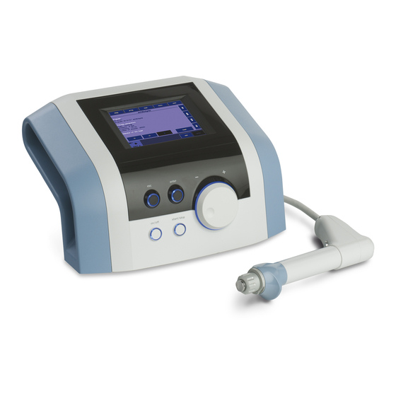
The device consists of two parts: the main unit and the applicator
Main Unit: BTL-6000 SWT Topline which contains the main microcomputer and software for controlling the entire system,in also includes the user encyclopaedia and the therapy guide.
Applicator – ergonomical applicator simplifies the „course of» the therapy, following the instructionsof the main unit.
The BTL-6000 SWT Topline is a state-of-the-art device allowing the application of therapy using non-invasive shockwaves. Shockwaves are one of the most effective ways to treat pain associated with the musculoskeletal system. Musculoskeletal pain is currently the second-leading cause of absences in the workplace.
The device consists of two parts:
∙Main Unit – contains the main microcomputer and software for controlling the entire system
∙Applicator – this ergonomically designed applicator will simplify the course of therapy
GENERAL CHARACTERISTICS OF THE DEVICE | PAGE 5 OF 38

1.2 SHOCKWAVE AND ITS CHARACTER
A shockwave is defined as a wave with a rapid increase of pressure within a very short time and then having a gradual decrease of pressure with a small negative pressure phase.
Shockwaves are aimed at the affected areas that are the source of chronic pain. The influence of the shockwaves causes to the dissolution of calcium deposits and leads to better vascularization. The after-effect is relief from the pain.
Outside of the client’s body (extra-corporeally), a pressure pulse of high amplitude is generated and its energy is concentrated on the target area. The pressure pulse travels through a liquid medium gel into the client’s body and penetrates soft tissue without major energy loss.
The pressure course of the shockwave in real-time in expressively different from the pressure course of the harmonic sound wave. Shockwaves can be compared to ultrasonic waves which are particularly characterized by a pressure jump change, a higher amplitude and non-periodicity.
In the shockwave, the positive amplitude is generally much larger than the negative amplitude. The frequency rate of the shockwaves is usually low (in Hz units) and the eventual cavitation (the disturbance of material consistency and the development of cavities) will relax. Consequently, there is no threat of energy absorption in the cavitations as is the case with continuous ultrasound.
A substantial part of the shockwave energy penetrates into the liquid (of the organism) with a great positive pressure pulse. Its diffusion is only limited by the actual tissue absorption and eventual reflections on acoustic non-homogeneities.
A shockwave is defined as a pressure pulse with these characteristics:
∙High positive pressure amplitude: 10 to 1000 MPa = 100 to 1000 Bar (100x atmospheric pressure)
∙Low negative pressure amplitude: 1 to 10 MPa
∙Short time duration: 1 µs to 20 µs
∙Rapid pressure increase: < 100 ns
∙Broad frequency spectrum: 1 Hz to 1 MHz
For therapeutic applications, these values are lower, especially the maximum pressure amplitude. The maximum pressure amplitude is about 15 MPa, the pulse length is 10 to 20 µs, and the frequency of the applied shockwave is 1 to 15Hz. The treatment is generally carried out without local anaesthesia and lasts about 15 to 30 minutes. During the first week after treatment, the client should avoid all physical activities that could excessively strain the treated area.
1.3 SHOCKWAVE GENERATION
Several types of generators have been developed for shockwave therapy, each producing shockwaves with varied characteristics. Each type of generation method induces shockwaves with different time progressions and spatial arrangements.
The BTL-6000 SWT Topline uses the ballistic principle of shockwave generation.
1.3.1BALLISTIC PRINCIPLE OF SHOCKWAVE GENERATION
A pressure wave is formed via a projectile by using accelerated compressed air. The compressed air is generated by an electronically-controlled ballistic-pressure compressor. Using elastic impact, the kinetic energy of the projectile is transferred into the probe of the applicator and then into the client’s body. Consequently, during the treatment, the end of the applicator must be in direct -contact with the skin and subcutaneous tissue.
GENERAL CHARACTERISTICS OF THE DEVICE | PAGE 6 OF 38

1.4 BIOLOGICAL EFFECTS OF SHOCKWAVE TREATMENT
The effects of the shockwaves mainly occur at sites where there is a change in impedance, such as the bone-soft tissue interface.
There is an improvement in the regeneration and repair of tissues in the following areas and the achievement of the following effects:
∙Cellular: Increase in cell membrane transmittance by improving ionic channels activity, stimulation of cell division, stimulation of cellular cytokines production.
∙Reproduction of vessels in the area of tendons and muscles: Improvement of blood circulation and MTB, increase in concentration of growth factor beta 1, chemotactic and mitogenic effect on osteoblasts.
∙Effect on nitrogen oxide system: Bone healing and re-modelling.
∙Improvement of micro-circulation and metabolism
∙Dissolution of calcified fibroblasts
∙Supports the production of collagen
∙Reduction in tissue tension
∙Analgesic effect:
o Destruction of afferent nerves and nerve receptors.
o CNS stimulants, sensed as pain, are also inflammation transmitter substances. o Regression of pain caused by local ischemia.
oGate control theory of pain.
1.5ADVANTAGES OF SHOCKWAVE TREATMENT
∙By the targeted application of the shockwaves, stress to the surrounding tissues is quite insignificant.
∙The body is not burdened by pharmaceuticals, except the short-term effect of local anaesthesia, if used.
∙The possibility of preventing the necessity of surgical intervention and its relevant hazards.
∙Thanks to ambulatory treatment, work absences are reduced to a minimum. Additionally, training routine absences for sport athletes is likewise reduced.
∙For some indications, such as Tennis Elbow, there is really no other effective treatment.
1.6POSSIBLE SIDE EFFECTS OF SHOCKWAVE TREATMENT
∙Erythema or swelling can temporarily occur in the treated area.
∙Loss of bodily sensation or itching can temporarily occur in the treated area
∙Hematoma
∙Petechiae
∙Skin damage after previous corticoid therapy
∙Shockwave application can cause undesirable heart activity
GENERAL CHARACTERISTICS OF THE DEVICE | PAGE 7 OF 38

1.7INDICATIONS FOR SHOCKWAVE TREATMENT
∙Plantar Fasciitis
∙Achillodynia/Achillobursitis
∙Inflammations and calcification of shoulder joint tendons.
∙Pain in the groin area.
∙Epicondylitis (Tennis and Golf Elbow)
∙Apex Patellae Syndrome and Tibial Stress Syndrome.
∙Pain in the hip area and/or the iliotibial tract.
∙Jumper’s Knee (Patellar Tendinitis)
∙Pain in the hamstring insertions.
∙Pain on the palmar side of the wrist.
∙Exostoses of small hand joints from Grade 1 Arthrosis.
∙Acupuncture
∙Pain trigger-points or painful points in muscles.
1.8CONTRA-INDICATIONS FOR SHOCKWAVE TREATMENT
∙Application to certain tissues: The eyes and the surrounding area, the myocardium, the spinal cord, the gonads, the kidneys and the liver
∙Blood disorders, coagulation problems or the use of anticoagulants
∙Blood thinning medications (Warfarinization)
∙Polypus in the area of treatment
∙Pregnancy
∙Thrombosis
∙Tumor diseases
∙Polyneuropathy
∙Acute inflammation
∙Growing cartilage in children
∙Therapy using corticoids
∙Inapplicable on areas of the body and organs with possible gas content
∙Inapplicable on areas in proximity to large nerve bundles, blood vessels, the spinal cord and the head
GENERAL CHARACTERISTICS OF THE DEVICE | PAGE 8 OF 38
2INSTRUCTIONS FOR OPERATION
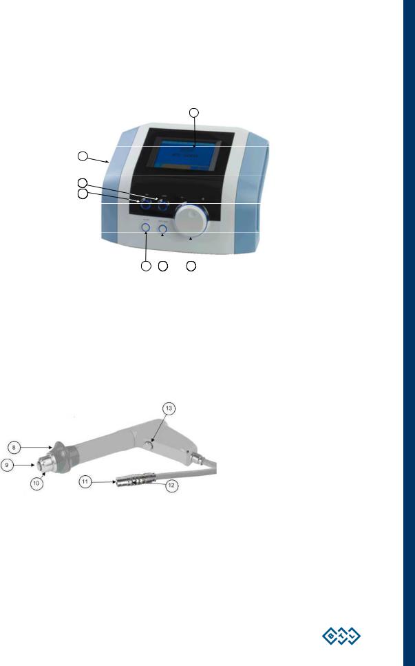
2.1THE FRONT PANEL OF THE BTL-6000 SWT TOPLINE
1
7
103
104
1.touch screen
2.select knob (to select individual parameters)
3.enter key
4.esc key
5.start / stop key (to start and stop therapy)
6.ON/OFF switch (back lit, in blue, when the control unit is ‘’on’’ )
7.USB port in the space of the device’s grip for use only in compliance with IEC 60950-1
The USB port serves only for service purposes such as upload of firmware; it is not designed for therapy use!
2.2APPLICATOR FOR BTL-6000 SWT TOPLINE
8.hand rest of the applicator
9.shock transmitter of the applicator
10.shock transmitter screw cap of the applicator
11.connector of the applicator
12.guide mark of the connector
13.applicator button: to start therapy
INSTRUCTIONS FOR OPERATION | PAGE 9 OF 38
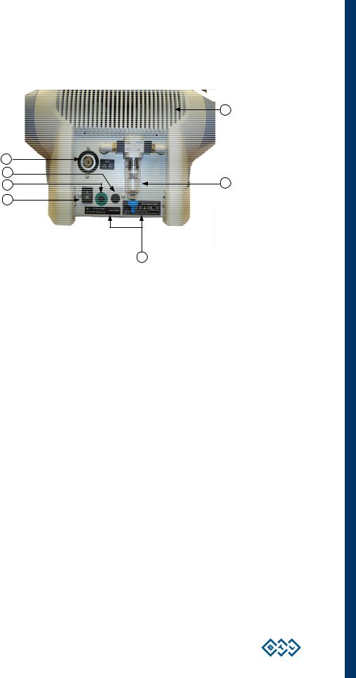
2.3THE REAR PANEL OF THE BTL-6000 SWT TOPLINE
14.connector for shockwave applicator
15.control unit mains fuse
16.connector for power cable
17.power on/off switch
18.vessel for collecting condensed water
19.type label – contains type of the device, manufacturer and safety and warning signs
20.venting grid
INSTRUCTIONS FOR OPERATION | PAGE 10 OF 38
![]()
2.4ASSEMBLY AND SET-UP
Inspect the box for damage and report any damage to the transport carrier and the distributor. Do not proceed with assembly and set-up if the box is damaged. Keep the original box and packaging to ensure safe future transport of the device.
When bringing the device from a cold environment into a warm one, do not plug it into the power source until the device has had to equilibrate to room temperature (Minimum 2 hours).
Unpack the device and place it on a stable horizontal surface which is suitable for its weight. Always position the device out of direct sunlight. During operation, the control unit gets warm, so it must not be positioned near direct heat sources. The device is self-cooled by forced air circulation. The cooling vents are located on the rear panel and on the bottom. Do not cover or block these vents. Allow a minimum of 4 inches (10cm) clearance behind the rear panel. Do not place the device on a soft surface (such as a towel) which may obstruct air flow to the bottom cooling vents. Do not put any heat-producing devices or any objects containing water or other liquids on the device. Do not put any heat-producing devices or objects containing water or other liquid on the device. Do not place the device close to appliances producing strong electromagnetic, electric or magnetic field (diathermy, X-rays, etc.), otherwise it could be undesirably influenced.
In the event of any questions, please contact an authorized service of BTL devices.
Procedure:
1.First connect the device in mains by means of the supplied power supply adapter, which you will connect to the connector on the rear panel of the device and to a 100 V or 240 V mains socket. The device detects the voltage automatically.
Plug the device directly into the mains socket. Do not use any multi-connection extension cables or two-socket adaptors.
2.Connect the applicator to the connector on the rear panel as follows:
Turn the applicator so that the red dot on its end is in straight line with the red dot on the output connector and only then plug the connector in.
When disconnecting the connector take the indented part of the applicator connector’s end in your fingers and pull slowly towards you to disconnect the connector carefully.
CAUTION! DO NOT TURN THE ENTIRE CONNECTED CONNECTOR BY FORCE, OTHERWISE THERE IS A RISK OF DAMAGE TO THE DEVICE!
The device detects the accessory, specifies its type and displays it on the screen in the appropriate tab. If you connect an improper accessory by mistake, the display shows a message with a help where to connect the given accessory.
3.Then switch on the power on/off switch on the rear panel of the device.
4.Press the on/off switch located on the front panel of the device.
Note:
After switching the device on, the device will run a self-diagnostic of its internal circuits and its functions for about 10 to 15 seconds. If any fault is detected, the screen will display a warning message. If necessary; the control unit will lock itself into a “secure” mode. If this situation occurs, please contact your authorized BTL distributor.
INSTRUCTIONS FOR OPERATION | PAGE 11 OF 38
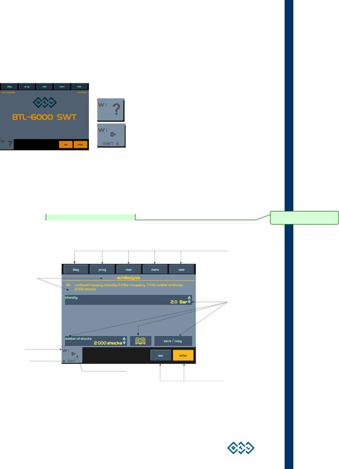
2.5BASIC DISPLAYS AND OPERATING OF THE DEVICE
2.5.1INITIAL SCREEN AND TYPES OF TABS
The initial screen after the switch-on of the device contains the tab displaying information about the connected accessories.
Examples of information shown on the tabs:
Indicates that no accessories are connected
Indicates that the applicator is connected and shockwave therapy can be applied.
2.5.2TOUCH SCREEN
The touch screen can display several graphic elements. Some are only for informative purposes but others can be pressed and activated. These basic elements include:
∙3D buttons which can be pressed to change the indicated values
∙Informative text
∙Channels tabs to switch between the channels and selection
The items on the touch screen can be pressed by a finger or by using a special pointer with a soft tip, so — called touchpen, which is included in the accessories of the device. The touch screen must not come in contact with any sharp objects, ball pens etc.
3D buttons of the menu
Information
3D buttons
Channel marking: W = shockwave
1 = No. of generator
|
Information about connected accessories |
Buttons with the same function as |
|
esc and enter on the control panel |
INSTRUCTIONS FOR OPERATION | PAGE 12 OF 38
Comment [andy1]: Neni dostupné této verzi
CONTENTS
1
GENERAL CHARACTERISTICS OF THE DEVICE…………………………………………………………………………………………………5
1.1
BTL-6000 SWT Topline System Series………………………………………………………………………………………………………………5
1.2
Shockwave and Its Character ……………………………………………………………………………………………………………………………6
1.3
Shockwave Generation…………………………………………………………………………………………………………………………………….6
1.3.1
1.4
1.5
Advantages of Shockwave Treatment ………………………………………………………………………………………………………………..7
1.6
1.7
Indications for Shockwave Treatment …………………………………………………………………………………………………………………8
1.8
2
INSTRUCTIONS FOR OPERATION……………………………………………………………………………………………………………………..9
2.1
2.2
Applicator for BTL-6000 SWT Topline ………………………………………………………………………………………………………………..9
2.3
2.4
Assembly and Set-Up…………………………………………………………………………………………………………………………………….11
2.5
2.5.1
Initial Screen and Types of Tabs ……………………………………………………………………………………………………………………12
2.5.2
Touch Screen……………………………………………………………………………………………………………………………………………..12
2.5.3
Numeric Keypad …………………………………………………………………………………………………………………………………………13
2.6
Setting of Therapy …………………………………………………………………………………………………………………………………………13
2.6.1
2.6.2
2.6.3
2.6.4
Setting the Number of Shocks……………………………………………………………………………………………………………………….14
2.6.5
Setting Therapy Intensity………………………………………………………………………………………………………………………………15
2.6.6
2.7
Course of Therapy…………………………………………………………………………………………………………………………………………16
2.7.1
Start, Interruption and End of Therapy…………………………………………………………………………………………………………….16
2.7.2
Running Therapy Screen ……………………………………………………………………………………………………………………………..17
2.7.3
End of Therapy / Generation of Shocks…………………………………………………………………………………………………………..17
2.8
Application of Shockwaves ……………………………………………………………………………………………………………………………..17
2.9
Saving Therapy …………………………………………………………………………………………………………………………………………….19
2.10 User Settings: The ‘user’ Button ………………………………………………………………………………………………………………………19
2.10.1 Clients……………………………………………………………………………………………………………………………………………………….20
2.10.2 User Diagnoses/Programs ……………………………………………………………………………………………………………………………20
2.10.3 Recent Therapies………………………………………………………………………………………………………………………………………..20
2.11 Unit Settings: The ‘menu’ Button ……………………………………………………………………………………………………………………..20
2.11.1 Accessories………………………………………………………………………………………………………………………………………………..20
2.11.1.1
Installation …………………………………………………………………………………………………………………………………………..20
2.11.1.2
Information…………………………………………………………………………………………………………………………………………..21
2.11.2 Encyclopaedia…………………………………………………………………………………………………………………………………………….21
2.11.3 Unit Settings……………………………………………………………………………………………………………………………………………….22
2.11.3.1
Password Setting………………………………………………………………………………………………………………………………….22
2.11.3.2
Sound Setting ………………………………………………………………………………………………………………………………………22
2.11.3.3
Screen Saver and Auto Switch-Off…………………………………………………………………………………………………………..22
2.11.3.4
Colour Setting ………………………………………………………………………………………………………………………………………22
2.11.3.5
Setting of Display Contrast……………………………………………………………………………………………………………………..23
2.11.3.6
Date and Time Setting …………………………………………………………………………………………………………………………..23
2.11.3.7
Language Setting………………………………………………………………………………………………………………………………….23
PAGE 3 OF 38
BTL-6000 SWT TOPLINE
USER’S MANUAL
v100AS08/01/2010EN
BEFORE YOU START
Dear Customer,
Thank you for purchasing BTL technology. All of us at BTL wish you every success with your system. We pride ourselves on being as responsive as possible to our customers’ needs. Your suggestions and comments are always welcome since we believe an ongoing relationship with our customers is critically important to our future product line.
While we would like you to start using your new equipment right away, we encourage a thorough reading of this manual in order to fully understand the operational features of the system.
Please visit our corporate website at http://www.btlnet.com for the latest information on BTL products and services.
Again, thank you for being a BTL customer.
BTL Industries, Ltd.
PAGE 2 OF 38
CONTENTS
|
1 GENERAL CHARACTERISTICS OF THE DEVICE………………………………………………………………………………………………… |
5 |
|||
|
1.1 |
BTL–6000 SWT Topline System Series……………………………………………………………………………………………………………… |
5 |
||
|
1.2 |
Shockwave and Its Character…………………………………………………………………………………………………………………………… |
6 |
||
|
1.3 |
Shockwave Generation……………………………………………………………………………………………………………………………………. |
6 |
||
|
1.3.1 |
Ballistic Principle of Shockwave Generation ……………………………………………………………………………………………………… |
6 |
||
|
1.4 |
Biological Effects of Shockwave Treatment ………………………………………………………………………………………………………… |
7 |
||
|
1.5 |
Advantages of Shockwave Treatment ……………………………………………………………………………………………………………….. |
7 |
||
|
1.6 |
Possible side Effects of Shockwave Treatment……………………………………………………………………………………………………. |
7 |
||
|
1.7 |
Indications for Shockwave Treatment ………………………………………………………………………………………………………………… |
8 |
||
|
1.8 |
Contra-indications for Shockwave Treatment………………………………………………………………………………………………………. |
8 |
||
|
2 INSTRUCTIONS FOR OPERATION…………………………………………………………………………………………………………………….. |
9 |
|||
|
2.1 |
The Front Panel of the BTL-6000 SWT Topline …………………………………………………………………………………………………… |
9 |
||
|
2.2 |
Applicator for BTL-6000 SWT Topline ……………………………………………………………………………………………………………….. |
9 |
||
|
2.3 |
The Rear Panel of the BTL-6000 SWT Topline………………………………………………………………………………………………….. |
10 |
||
|
2.4 |
Assembly and Set-Up……………………………………………………………………………………………………………………………………. |
11 |
||
|
2.5 |
Basic Displays and Operating of the Device ……………………………………………………………………………………………………… |
12 |
||
|
2.5.1 |
Initial Screen and Types of Tabs …………………………………………………………………………………………………………………… |
12 |
||
|
2.5.2 |
Touch Screen…………………………………………………………………………………………………………………………………………….. |
12 |
||
|
2.5.3 |
Numeric Keypad ………………………………………………………………………………………………………………………………………… |
13 |
||
|
2.6 |
Setting of Therapy ………………………………………………………………………………………………………………………………………… |
13 |
||
|
2.6.1 |
Setting Therapy Parameters Via the ‘diag’ Button ……………………………………………………………………………………………. |
13 |
||
|
2.6.2 |
Setting Therapy Parameters Via the ‘prog’ Button ……………………………………………………………………………………………. |
13 |
||
|
2.6.3 |
Setting Therapy Parameters Manually (User Setup) Via the ‘man’ Button …………………………………………………………… |
14 |
||
|
2.6.4 |
Setting the Number of Shocks………………………………………………………………………………………………………………………. |
14 |
||
|
2.6.5 |
Setting Therapy Intensity……………………………………………………………………………………………………………………………… |
15 |
||
|
2.6.6 |
Therapy Parameters Screen – Ergonomic, Standard and Expert Mode……………………………………………………………….. |
16 |
||
|
2.7 |
Course of Therapy………………………………………………………………………………………………………………………………………… |
16 |
||
|
2.7.1 |
Start, Interruption and End of Therapy……………………………………………………………………………………………………………. |
16 |
||
|
2.7.2 |
Running Therapy Screen …………………………………………………………………………………………………………………………….. |
17 |
||
|
2.7.3 |
End of Therapy / Generation of Shocks………………………………………………………………………………………………………….. |
17 |
||
|
2.8 |
Application of Shockwaves …………………………………………………………………………………………………………………………….. |
17 |
||
|
2.9 |
Saving Therapy ……………………………………………………………………………………………………………………………………………. |
19 |
||
|
2.10 |
User Settings: The ‘user’ Button ……………………………………………………………………………………………………………………… |
19 |
||
|
2.10.1 |
Clients………………………………………………………………………………………………………………………………………………………. |
20 |
||
|
2.10.2 |
User Diagnoses/Programs …………………………………………………………………………………………………………………………… |
20 |
||
|
2.10.3 |
Recent Therapies……………………………………………………………………………………………………………………………………….. |
20 |
||
|
2.11 |
Unit Settings: The ‘menu’ Button …………………………………………………………………………………………………………………….. |
20 |
||
|
2.11.1 |
Accessories……………………………………………………………………………………………………………………………………………….. |
20 |
||
|
2.11.1.1 |
Installation ………………………………………………………………………………………………………………………………………….. |
20 |
||
|
2.11.1.2 |
Information………………………………………………………………………………………………………………………………………….. |
21 |
||
|
2.11.2 |
Encyclopaedia……………………………………………………………………………………………………………………………………………. |
21 |
||
|
2.11.3 |
Unit Settings………………………………………………………………………………………………………………………………………………. |
22 |
||
|
2.11.3.1 |
Password Setting…………………………………………………………………………………………………………………………………. |
22 |
||
|
2.11.3.2 |
Sound Setting ……………………………………………………………………………………………………………………………………… |
22 |
||
|
2.11.3.3 |
Screen Saver and Auto Switch-Off………………………………………………………………………………………………………….. |
22 |
||
|
2.11.3.4 |
Colour Setting……………………………………………………………………………………………………………………………………… |
22 |
||
|
2.11.3.5 |
Setting of Display Contrast…………………………………………………………………………………………………………………….. |
23 |
||
|
2.11.3.6 |
Date and Time Setting ………………………………………………………………………………………………………………………….. |
23 |
||
|
2.11.3.7 |
Language Setting…………………………………………………………………………………………………………………………………. |
23 |
PAGE 3 OF 38
|
2.11.3.8 |
Operation Mode …………………………………………………………………………………………………………………………………… |
23 |
|
|
2.11.3.9 |
Touch Panel Calibration………………………………………………………………………………………………………………………… |
23 |
|
|
2.11.3.10 |
User Options……………………………………………………………………………………………………………………………………….. |
23 |
|
|
2.11.3.11 |
Setting of HW Key ……………………………………………………………………………………………………………………………….. |
23 |
|
|
2.11.3.12 |
Unit Information …………………………………………………………………………………………………………………………………… |
23 |
|
|
2.11.3.13 |
Unlock Code ……………………………………………………………………………………………………………………………………….. |
23 |
|
|
2.11.3.14 |
Service Functions ………………………………………………………………………………………………………………………………… |
24 |
|
|
2.11.4 Specific Settings ………………………………………………………………………………………………………………………………………… |
24 |
||
|
2.11.4.1 |
Applicator Button Mode…………………………………………………………………………………………………………………………. |
24 |
|
|
2.11.4.2 |
Applicator Kit Replacement Wizard …………………………………………………………………………………………………………. |
24 |
|
|
3 LIST OF STANDARD AND OPTIONAL ACCESSORIES ………………………………………………………………………………………. |
25 |
||
|
4 MAINTENANCE AND SAFETY INSTRUCTIONS…………………………………………………………………………………………………. |
26 |
||
|
4.1.1 Shock Transmitter Replacement Procedure ……………………………………………………………………………………………………. |
27 |
||
|
4.1.2 Procedure of Worn-out Tube and Projectile Replacement …………………………………………………………………………………. |
28 |
||
|
4.2 |
General Safety Precautions……………………………………………………………………………………………………………………………. |
31 |
|
|
4.3 |
Used Symbols ……………………………………………………………………………………………………………………………………………… |
32 |
|
|
4.4 |
Warranty……………………………………………………………………………………………………………………………………………………… |
32 |
|
|
5 |
TECHNICAL PARAMETERS ……………………………………………………………………………………………………………………………. |
33 |
|
|
5.1 |
EMC Information ………………………………………………………………………………………………………………………………………….. |
35 |
|
|
5.2 |
Applicable Standards…………………………………………………………………………………………………………………………………….. |
37 |
|
|
5.3 |
Manufacturer ……………………………………………………………………………………………………………………………………………….. |
38 |
PAGE 4 OF 38
1 GENERAL CHARACTERISTICS OF THE DEVICE
The BTL-6000 SWT Topline is a state-of-the-art device allowing the application of therapy using non-invasive shockwaves. Shockwaves are one of the most effective ways to treat pain associated with the musculoskeletal system. Musculoskeletal pain is currently the second-leading cause of absences in the workplace.
The device is equipped with a color touch screen on the main unit which considerably simplifies its use. The touch screen is equipped with a stylus (touch-pen) for easy operation of the device. The horizontally orientation of the device allows the information on the screen to be seen clearly from different servicing positions. Additionally, the brightness of the screen can be set to match the lighting in the room of the office or the health-care center. The on-screen information will guide the user step- by-step through the entire therapy process. The therapeutic parameters are easily set using the touch screen buttons and knobs/keys on the device.
Therapy is easily and efficiently started by simply selecting a diagnosis from an alphabetized list of treatment protocols or by selecting a therapy program. The treatment parameters can be manually set by the simple use of the touch screen buttons. Throughout the course of a therapy session, the device will keep the user informed about the therapeutic method in use, the type of treatment, the total number of shocks to be applied, the number of shocks applied and remaining, the frequency being used, the intensity and other necessary data.
A time-saving feature of the BTL-6000 SWT Topline is the predefined programs stored in the memory of the main unit. Based on detailed research and practical use of the device, the well-organized predefined programs will provide recommendations for the treatment of various conditions.
The BTL-6000 SWT Topline allows the entering of client names and other relevant information into the internal memory of the device and to link their data with the predefined programs or with the user’s own. When a client has a return visit, simply call up their name and begin the pre-set therapy.
We also carry a specially-designed cart for the BTL-6000 SWT Topline which is sold separately. The design allows convenient movement and use of the device. Four stable castors ensure smooth and easy movement of the device in the office or the health-care center.
For the latest information on BTL products and services, please visit our corporate website at http://www.btlnet.com.
1.1BTL–6000 SWT TOPLINE SYSTEM SERIES
The device consists of two parts: the main unit and the applicator
Main Unit: BTL-6000 SWT Topline which contains the main microcomputer and software for controlling the entire system,in also includes the user encyclopaedia and the therapy guide.
Applicator – ergonomical applicator simplifies the „course of» the therapy, following the instructionsof the main unit.
The BTL-6000 SWT Topline is a state-of-the-art device allowing the application of therapy using non-invasive shockwaves. Shockwaves are one of the most effective ways to treat pain associated with the musculoskeletal system. Musculoskeletal pain is currently the second-leading cause of absences in the workplace.
The device consists of two parts:
∙Main Unit – contains the main microcomputer and software for controlling the entire system
∙Applicator – this ergonomically designed applicator will simplify the course of therapy
GENERAL CHARACTERISTICS OF THE DEVICE | PAGE 5 OF 38
1.2 SHOCKWAVE AND ITS CHARACTER
A shockwave is defined as a wave with a rapid increase of pressure within a very short time and then having a gradual decrease of pressure with a small negative pressure phase.
Shockwaves are aimed at the affected areas that are the source of chronic pain. The influence of the shockwaves causes to the dissolution of calcium deposits and leads to better vascularization. The after-effect is relief from the pain.
Outside of the client’s body (extra-corporeally), a pressure pulse of high amplitude is generated and its energy is concentrated on the target area. The pressure pulse travels through a liquid medium gel into the client’s body and penetrates soft tissue without major energy loss.
The pressure course of the shockwave in real-time in expressively different from the pressure course of the harmonic sound wave. Shockwaves can be compared to ultrasonic waves which are particularly characterized by a pressure jump change, a higher amplitude and non-periodicity.
In the shockwave, the positive amplitude is generally much larger than the negative amplitude. The frequency rate of the shockwaves is usually low (in Hz units) and the eventual cavitation (the disturbance of material consistency and the development of cavities) will relax. Consequently, there is no threat of energy absorption in the cavitations as is the case with continuous ultrasound.
A substantial part of the shockwave energy penetrates into the liquid (of the organism) with a great positive pressure pulse. Its diffusion is only limited by the actual tissue absorption and eventual reflections on acoustic non-homogeneities.
A shockwave is defined as a pressure pulse with these characteristics:
∙High positive pressure amplitude: 10 to 1000 MPa = 100 to 1000 Bar (100x atmospheric pressure)
∙Low negative pressure amplitude: 1 to 10 MPa
∙Short time duration: 1 µs to 20 µs
∙Rapid pressure increase: < 100 ns
∙Broad frequency spectrum: 1 Hz to 1 MHz
For therapeutic applications, these values are lower, especially the maximum pressure amplitude. The maximum pressure amplitude is about 15 MPa, the pulse length is 10 to 20 µs, and the frequency of the applied shockwave is 1 to 15Hz. The treatment is generally carried out without local anaesthesia and lasts about 15 to 30 minutes. During the first week after treatment, the client should avoid all physical activities that could excessively strain the treated area.
1.3 SHOCKWAVE GENERATION
Several types of generators have been developed for shockwave therapy, each producing shockwaves with varied characteristics. Each type of generation method induces shockwaves with different time progressions and spatial arrangements.
The BTL-6000 SWT Topline uses the ballistic principle of shockwave generation.
1.3.1BALLISTIC PRINCIPLE OF SHOCKWAVE GENERATION
A pressure wave is formed via a projectile by using accelerated compressed air. The compressed air is generated by an electronically-controlled ballistic-pressure compressor. Using elastic impact, the kinetic energy of the projectile is transferred into the probe of the applicator and then into the client’s body. Consequently, during the treatment, the end of the applicator must be in direct -contact with the skin and subcutaneous tissue.
GENERAL CHARACTERISTICS OF THE DEVICE | PAGE 6 OF 38
1.4 BIOLOGICAL EFFECTS OF SHOCKWAVE TREATMENT
The effects of the shockwaves mainly occur at sites where there is a change in impedance, such as the bone-soft tissue interface.
There is an improvement in the regeneration and repair of tissues in the following areas and the achievement of the following effects:
∙Cellular: Increase in cell membrane transmittance by improving ionic channels activity, stimulation of cell division, stimulation of cellular cytokines production.
∙Reproduction of vessels in the area of tendons and muscles: Improvement of blood circulation and MTB, increase in concentration of growth factor beta 1, chemotactic and mitogenic effect on osteoblasts.
∙Effect on nitrogen oxide system: Bone healing and re-modelling.
∙Improvement of micro-circulation and metabolism
∙Dissolution of calcified fibroblasts
∙Supports the production of collagen
∙Reduction in tissue tension
∙Analgesic effect:
o Destruction of afferent nerves and nerve receptors.
o CNS stimulants, sensed as pain, are also inflammation transmitter substances. o Regression of pain caused by local ischemia.
oGate control theory of pain.
1.5ADVANTAGES OF SHOCKWAVE TREATMENT
∙By the targeted application of the shockwaves, stress to the surrounding tissues is quite insignificant.
∙The body is not burdened by pharmaceuticals, except the short-term effect of local anaesthesia, if used.
∙The possibility of preventing the necessity of surgical intervention and its relevant hazards.
∙Thanks to ambulatory treatment, work absences are reduced to a minimum. Additionally, training routine absences for sport athletes is likewise reduced.
∙For some indications, such as Tennis Elbow, there is really no other effective treatment.
1.6POSSIBLE SIDE EFFECTS OF SHOCKWAVE TREATMENT
∙Erythema or swelling can temporarily occur in the treated area.
∙Loss of bodily sensation or itching can temporarily occur in the treated area
∙Hematoma
∙Petechiae
∙Skin damage after previous corticoid therapy
∙Shockwave application can cause undesirable heart activity
GENERAL CHARACTERISTICS OF THE DEVICE | PAGE 7 OF 38
1.7INDICATIONS FOR SHOCKWAVE TREATMENT
∙Plantar Fasciitis
∙Achillodynia/Achillobursitis
∙Inflammations and calcification of shoulder joint tendons.
∙Pain in the groin area.
∙Epicondylitis (Tennis and Golf Elbow)
∙Apex Patellae Syndrome and Tibial Stress Syndrome.
∙Pain in the hip area and/or the iliotibial tract.
∙Jumper’s Knee (Patellar Tendinitis)
∙Pain in the hamstring insertions.
∙Pain on the palmar side of the wrist.
∙Exostoses of small hand joints from Grade 1 Arthrosis.
∙Acupuncture
∙Pain trigger-points or painful points in muscles.
1.8CONTRA-INDICATIONS FOR SHOCKWAVE TREATMENT
∙Application to certain tissues: The eyes and the surrounding area, the myocardium, the spinal cord, the gonads, the kidneys and the liver
∙Blood disorders, coagulation problems or the use of anticoagulants
∙Blood thinning medications (Warfarinization)
∙Polypus in the area of treatment
∙Pregnancy
∙Thrombosis
∙Tumor diseases
∙Polyneuropathy
∙Acute inflammation
∙Growing cartilage in children
∙Therapy using corticoids
∙Inapplicable on areas of the body and organs with possible gas content
∙Inapplicable on areas in proximity to large nerve bundles, blood vessels, the spinal cord and the head
GENERAL CHARACTERISTICS OF THE DEVICE | PAGE 8 OF 38
2INSTRUCTIONS FOR OPERATION
2.1THE FRONT PANEL OF THE BTL-6000 SWT TOPLINE
1
7
103
104
1.touch screen
2.select knob (to select individual parameters)
3.enter key
4.esc key
5.start / stop key (to start and stop therapy)
6.ON/OFF switch (back lit, in blue, when the control unit is ‘’on’’ )
7.USB port in the space of the device’s grip for use only in compliance with IEC 60950-1
The USB port serves only for service purposes such as upload of firmware; it is not designed for therapy use!
2.2APPLICATOR FOR BTL-6000 SWT TOPLINE
8.hand rest of the applicator
9.shock transmitter of the applicator
10.shock transmitter screw cap of the applicator
11.connector of the applicator
12.guide mark of the connector
13.applicator button: to start therapy
INSTRUCTIONS FOR OPERATION | PAGE 9 OF 38
2.3THE REAR PANEL OF THE BTL-6000 SWT TOPLINE
14.connector for shockwave applicator
15.control unit mains fuse
16.connector for power cable
17.power on/off switch
18.vessel for collecting condensed water
19.type label – contains type of the device, manufacturer and safety and warning signs
20.venting grid
INSTRUCTIONS FOR OPERATION | PAGE 10 OF 38
![]()
2.4ASSEMBLY AND SET-UP
Inspect the box for damage and report any damage to the transport carrier and the distributor. Do not proceed with assembly and set-up if the box is damaged. Keep the original box and packaging to ensure safe future transport of the device.
When bringing the device from a cold environment into a warm one, do not plug it into the power source until the device has had to equilibrate to room temperature (Minimum 2 hours).
Unpack the device and place it on a stable horizontal surface which is suitable for its weight. Always position the device out of direct sunlight. During operation, the control unit gets warm, so it must not be positioned near direct heat sources. The device is self-cooled by forced air circulation. The cooling vents are located on the rear panel and on the bottom. Do not cover or block these vents. Allow a minimum of 4 inches (10cm) clearance behind the rear panel. Do not place the device on a soft surface (such as a towel) which may obstruct air flow to the bottom cooling vents. Do not put any heat-producing devices or any objects containing water or other liquids on the device. Do not put any heat-producing devices or objects containing water or other liquid on the device. Do not place the device close to appliances producing strong electromagnetic, electric or magnetic field (diathermy, X-rays, etc.), otherwise it could be undesirably influenced.
In the event of any questions, please contact an authorized service of BTL devices.
Procedure:
1.First connect the device in mains by means of the supplied power supply adapter, which you will connect to the connector on the rear panel of the device and to a 100 V or 240 V mains socket. The device detects the voltage automatically.
Plug the device directly into the mains socket. Do not use any multi-connection extension cables or two-socket adaptors.
2.Connect the applicator to the connector on the rear panel as follows:
Turn the applicator so that the red dot on its end is in straight line with the red dot on the output connector and only then plug the connector in.
When disconnecting the connector take the indented part of the applicator connector’s end in your fingers and pull slowly towards you to disconnect the connector carefully.
CAUTION! DO NOT TURN THE ENTIRE CONNECTED CONNECTOR BY FORCE, OTHERWISE THERE IS A RISK OF DAMAGE TO THE DEVICE!
The device detects the accessory, specifies its type and displays it on the screen in the appropriate tab. If you connect an improper accessory by mistake, the display shows a message with a help where to connect the given accessory.
3.Then switch on the power on/off switch on the rear panel of the device.
4.Press the on/off switch located on the front panel of the device.
Note:
After switching the device on, the device will run a self-diagnostic of its internal circuits and its functions for about 10 to 15 seconds. If any fault is detected, the screen will display a warning message. If necessary; the control unit will lock itself into a “secure” mode. If this situation occurs, please contact your authorized BTL distributor.
INSTRUCTIONS FOR OPERATION | PAGE 11 OF 38
2.5BASIC DISPLAYS AND OPERATING OF THE DEVICE
2.5.1INITIAL SCREEN AND TYPES OF TABS
The initial screen after the switch-on of the device contains the tab displaying information about the connected accessories.
Examples of information shown on the tabs:
Indicates that no accessories are connected
Indicates that the applicator is connected and shockwave therapy can be applied.
2.5.2TOUCH SCREEN
The touch screen can display several graphic elements. Some are only for informative purposes but others can be pressed and activated. These basic elements include:
∙3D buttons which can be pressed to change the indicated values
∙Informative text
∙Channels tabs to switch between the channels and selection
The items on the touch screen can be pressed by a finger or by using a special pointer with a soft tip, so — called touchpen, which is included in the accessories of the device. The touch screen must not come in contact with any sharp objects, ball pens etc.
3D buttons of the menu
Information
3D buttons
Channel marking: W = shockwave
1 = No. of generator
|
Information about connected accessories |
Buttons with the same function as |
|
esc and enter on the control panel |
INSTRUCTIONS FOR OPERATION | PAGE 12 OF 38
Comment [andy1]: Neni dostupné této verzi
Loading…