-
Contents
-
Table of Contents
-
Bookmarks
Quick Links
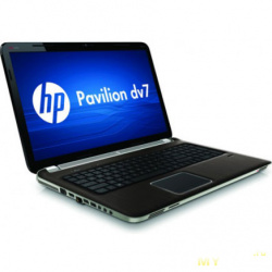
HP Pavilion dv7 Entertainment PC
Maintenance and Service Guide
Downloaded from LpManual.com Manuals
Related Manuals for HP Pavilion dv7
Summary of Contents for HP Pavilion dv7
-
Page 1
HP Pavilion dv7 Entertainment PC Maintenance and Service Guide Downloaded from LpManual.com Manuals… -
Page 2
The information contained herein is subject to change without notice. The only warranties for HP products and services are set forth in the express warranty statements accompanying such products and services. Nothing herein should be construed as constituting an additional warranty. -
Page 3
Safety warning notice WARNING! To reduce the possibility of heat-related injuries or of overheating the computer, do not place the computer directly on your lap or obstruct the computer air vents. Use the computer only on a hard, flat surface. Do not allow another hard surface, such as an adjoining optional printer, or a soft surface, such as pillows or rugs or clothing, to block airflow. -
Page 4
Safety warning notice Downloaded from LpManual.com Manuals… -
Page 5: Table Of Contents
Table of contents 1 Product description 2 Components Top components ……………………… 6 TouchPad ……………………..6 Lights ……………………… 7 Buttons and fingerprint reader (select models only) …………9 Keys ……………………… 11 Front components ……………………..12 Rear component ……………………..13 Right-side components ……………………13 Left-side components …………………….
-
Page 6
Electrostatic discharge damage ……………. 38 Packaging and transporting guidelines ……….39 Workstation guidelines …………..39 Equipment guidelines …………… 40 Component replacement procedures ………………..41 Service tag ……………………. 41 Computer feet ……………………42 Battery ……………………..43 Optical drive ……………………44 Primary hard drive cover ………………..45 Secondary hard drive cover ……………….. -
Page 7
System Configuration menu ………………..98 Diagnostics menu ………………….99 6 Specifications Computer specifications ……………………100 17.3-inch, HD+ flush glass AntiGlare display specifications …………101 17.3-inch HD+ BrightView display specifications …………….102 Hard drive specifications ……………………103 Blu-ray ROM DVD±R/RW SuperMulti DL Drive …………….104 DVD±RW and CD-RW SuperMulti Double-Layer Combo Drive specifications …….. -
Page 8
9 Connector pin assignments 1394 …………………………138 Audio-in (microphone) ……………………138 Audio-out (headphone) ……………………139 External monitor ……………………..139 HDMI …………………………140 RJ-11 (modem) ……………………..141 RJ-45 (network) ……………………..141 Universal Serial Bus ……………………. 142 10 Power cord set requirements Requirements for all countries or regions ……………… -
Page 9: Product Description
Product description Category Description Product Name HP Pavilion dv7 Entertainment PC Processors Intel® Core™2 Quad Q9100 2.26-GHz with 12-MB L2 cache and 1066-MHz front side bus (FSB) Intel Core2 Quad Q9000 2.00-GHz with 12-MB L2 cache and 1066-MHz FSB Intel Core2 Duo T9800 2.93-GHz with 6-MB L2 cache and 1066-MHz FSB Intel Core2 Duo T9550 2.66-GHz with 6-MB L2 cache and 1066-MHz FSB…
-
Page 10
Category Description Discrete graphics subsystem memory ● ATI Mobility Radeon HD 4650 (M96) with 1024 MB (64 MB × 16 DDR3 × 8 PCs) ● ATI Mobility Radeon HD 4530 (M92) with 512 MB (64 MB × 16 DDR3 × 4 PCs) ●… -
Page 11
Category Description Single hard drive configurations: ● 500-GB, 5400-rpm ● 320-GB, 7200-rpm ● 320-GB, 5400-rpm ● 250-GB, 7200-rpm ● 250-GB, 5400-rpm Optical drives 12.7-mm tray load Serial ATA Fixed (1 screw for removal) Support for the following optical drives: ● DVD±RW and CD-RW SuperMulti Double-Layer Combo Drive with LightScribe ●… -
Page 12
TV tuner antenna (select models only) USB 2.0 VGA (Dsub 15-pin) 2-pin AC power for 90-W AC adapter Docking Expansion port 3 supports the HP Notebook Expansion Base and HP Notebook QuickDock Keyboard/pointing devices 17-inch full-size keyboard with numeric keypad TouchPad supports 2-way scrolling… -
Page 13
Category Description Serviceability AC adapter Battery (system) Hard drives (2) Memory module Optical drive Downloaded from LpManual.com Manuals… -
Page 14: Components
Components Top components TouchPad Component Description TouchPad light ● White: TouchPad is enabled. ● Amber: TouchPad is disabled. TouchPad* Moves the pointer and selects or activates items on the screen. Left TouchPad button* Functions like the left button on an external mouse. TouchPad on/off button Enables/disables the TouchPad.
-
Page 15: Lights
Lights Component Description Caps lock light On: Caps lock is on. ● Power lights (2)* On: The computer is on. ● Blinking: The computer is in the Sleep state. ● Off: The computer is off or in Hibernation. ● Volume mute light White: Computer sound is on.
-
Page 16
Blinking: The hard drive or optical drive is being accessed. ● Amber: HP 3D DriveGuard has temporarily parked the hard drive. *The 2 power lights display the same information. The light on the power button is visible only when the computer is open. The power light on the front of the computer is visible whether the computer is open or closed. -
Page 17: Buttons And Fingerprint Reader (Select Models Only)
Buttons and fingerprint reader (select models only) Component Description Power button* ● When the computer is off, press the button to turn on the computer. ● When the computer is on, press the button briefly to initiate Sleep. ● When the computer is in the Sleep state, press the button briefly to exit Sleep.
-
Page 18
Component Description ● Next/fast forward button Plays the next track or chapter when the button is pressed once. ● Fast forwards media when pressed in combination with the key. Stop button Stops playback. Wireless button Turns the wireless feature on or off but does not create a wireless connection. -
Page 19: Keys
Keys Component Description Displays system information when pressed in combination with key. Executes frequently used system functions when pressed in combination with a function key or the key. Windows logo key Displays the Windows Start menu. Windows applications key Displays a shortcut menu for items beneath the pointer. Integrated numeric keypad keys Can be used like the keys on an external numeric keypad.
-
Page 20: Front Components
● Drive light Blinking: The hard drive or optical drive is being accessed. ● Amber: HP 3D DriveGuard has temporarily parked the hard drive. Consumer infrared lens Receives a signal from the remote control. Audio-in (microphone) jack Connects an optional computer headset microphone, stereo array microphone, or monaural microphone.
-
Page 21: Rear Component
Rear component Component Description Vent Enables airflow to cool internal components. NOTE: The computer fan starts up automatically to cool internal components and prevent overheating. It is normal for the internal fan to cycle on and off during routine operation. Right-side components Component Description…
-
Page 22: Left-Side Components
Left-side components Component Description External monitor port Connects an external VGA monitor or projector. Expansion port 3 Connects the computer to an optional docking device or an optional expansion product. NOTE: The computer has only one expansion port. The term expansion port 3 describes the type of expansion port.
-
Page 23: Bottom Components
Bottom components Component Description Battery bay Holds the battery. Battery release latch Releases the battery from the battery bay. Vents (9) Enable airflow to cool internal components. NOTE: The computer fan starts up automatically to cool internal components and prevent overheating. It is normal for the internal fan to cycle on and off during routine operation.
-
Page 24: Display Components
Display components Component Description Internal display switch Turns off the display and initiates Sleep if the display is closed while the power is on. Internal microphones (2) Record sound. Webcam light On: The webcam is in use. Webcam Records audio and video and captures still photographs. Chapter 2 Components Downloaded from LpManual.com Manuals…
-
Page 25: Illustrated Parts Catalog
Illustrated parts catalog Service tag When ordering parts or requesting information, provide the computer serial number and model description provided on the service tag. (1) Product name: This is the product name affixed to the front of the computer. (2) Serial number (s/n): This is an alphanumeric identifier that is unique to each product. (3) Part number/Product number (p/n): This number provides specific information about the product’s hardware components.
-
Page 26: Computer Major Components
Computer major components Chapter 3 Illustrated parts catalog Downloaded from LpManual.com Manuals…
-
Page 27
Item Description Spare part number 17.3-inch display assembly (includes wireless antenna transceivers and cables) HD+ flush glass AntiGlare display assembly with webcam and 2 microphones for use 516296-001 in white computers HD+ BrightView display assembly with webcam and 2 microphones for use in white 516295-001 computers HD+ flush glass AntiGlare display assembly with webcam and 2 microphones for use… -
Page 28
Item Description Spare part number (10) Modem module NOTE: The modem module spare part kit does not include a modem module cable. The modem module cable is included in the Cable Kit, spare part number 516328-001. For use in all countries and regions except Australia and New Zealand 461749-001 For use only in Australia and New Zealand 461749-011… -
Page 29
Item Description Spare part number (17) USB board (includes cable) For use in computers with discrete graphics subsystems 516332-001 For use in computers with UMA graphics subsystems 518168-001 (18) Base enclosure (includes rubber feet) For use only with computer models equipped with an Intel Core2 Quad processor 516298-001 For use only in defeatured computer models equipped with an Intel Core2 Duo 516297-001… -
Page 30
Item Description Spare part number Broadcom 4322 802.11a/b/g/n WLAN module for use in Afghanistan, Albania, Algeria, 504664-002 Andorra, Angola, Antigua and Barbuda, Argentina, Armenia, Aruba, Australia, Austria, Azerbaijan, the Bahamas, Bahrain, Bangladesh, Barbados, Belarus, Belgium, Belize, Benin, Bermuda, Bhutan, Bolivia, Bosnia and Herzegovina, Botswana, Brazil, the British Virgin Islands, Brunei, Bulgaria, Burkina Faso, Burundi, Cameroon, Cape Verde, the Central African Republic, Chad, Chile, the People’s Republic of China, Colombia, Comoros, the Congo, Costa Rica, Croatia, Cyprus, the Czech Republic,… -
Page 31
Item Description Spare part number Broadcom BCM4312 802.11b/g WLAN module for use in Afghanistan, Albania, Algeria, 504593-002 Andorra, Angola, Antigua and Barbuda, Argentina, Armenia, Aruba, Australia, Austria, Azerbaijan, the Bahamas, Bahrain, Bangladesh, Barbados, Belarus, Belgium, Belize, Benin, Bermuda, Bhutan, Bolivia, Bosnia and Herzegovina, Botswana, Brazil, the British Virgin Islands, Brunei, Bulgaria, Burkina Faso, Burundi, Cameroon, Cape Verde, the Central African Republic, Chad, Chile, the People’s Republic of China, Colombia, Comoros, the Congo, Costa Rica, Croatia, Cyprus, the Czech Republic, Denmark,… -
Page 32: Display Assembly Components
Display assembly components Flush glass display assembly spare parts Item Description Spare part number Display enclosure (includes wireless antenna transceivers and cables and logo LED board and cable) For use in white computers 516443-001 For use in black computers 519262-001 Webcam/microphone module 516312-001 Display Hinge Kit (includes right and left hinges)
-
Page 33: Brightview Panel
BrightView panel Item Description Spare part number Display bezel 516305-001 Display Hinge Kit (includes left and right hinges) 516306-001 Webcam/microphone module 516312-001 Display panel (includes display panel cable) 516303-001 Display Cable Kit (includes display panel cable, and microphone receiver and cable) 516307-001 Display enclosure (includes wireless antenna transceivers and cables and logo LED board and cable)
-
Page 34: Mass Storage Devices
Mass storage devices Item Description Spare part number Hard drive (includes left and right bracket rails, connector cable, Mylar cover with tab, and 4 rubber isolators): ● 500-GB, 5400-rpm 516350-001 ● 320-GB, 7200-rpm 516349-001 ● 320-GB, 5400-rpm 516346-001 ● 250-GB, 7200-rpm 516348-001 ●…
-
Page 35: Miscellaneous Parts
Miscellaneous parts Description Spare part number AC adapters 120-W AC adapter 463953-001 90-W AC adapter 463955-001 65-W AC adapter 463958-001 Wired headset with volume control 371693-001 Wireless laser mouse (includes infrared transceiver) 430958-001 Power cords: Australia and New Zealand 490371-011 Belgium, Bulgaria, the Czech Republic, Finland, France, Germany, Greece, Hungary, Iceland, the 490371-021 Netherlands, northwest Africa, Norway, Poland, Portugal, Russia, Slovakia, Spain, Sweden, and…
-
Page 36: Sequential Part Number Listing
Sequential part number listing Spare part Description number 371693-003 Wired headset with volume control 430958-001 Wireless laser mouse (includes infrared transceiver) 449729-001 RTC battery 459263-002 Broadcom BCM4312 802.11b/g WLAN module for use only with computer models equipped with Intel processors in Afghanistan, Albania, Algeria, Andorra, Angola, Antigua and Barbuda, Argentina, Armenia, Aruba, Australia, Austria, Azerbaijan, the Bahamas, Bahrain, Bangladesh, Barbados, Belarus, Belgium, Belize, Benin, Bermuda, Bhutan, Bolivia, Bosnia and Herzegovina, Botswana, Brazil, the British Virgin Islands, Brunei, Bulgaria, Burkina Faso, Burundi, Cameroon, Cape Verde,…
-
Page 37
Spare part Description number 482899-002 DVB-T/ANG TV tuner module NOTE: The TV tuner module spare part kit does not include a TV tuner module cable. The TV tuner module cable is included in the Cable Kit, spare part number 501891-001. 482899-003 DVB-T TV tuner module NOTE:… -
Page 38
Spare part Description number 504593-002 Broadcom BCM4312 802.11b/g WLAN module for use in Afghanistan, Albania, Algeria, Andorra, Angola, Antigua and Barbuda, Argentina, Armenia, Aruba, Australia, Austria, Azerbaijan, the Bahamas, Bahrain, Bangladesh, Barbados, Belarus, Belgium, Belize, Benin, Bermuda, Bhutan, Bolivia, Bosnia and Herzegovina, Botswana, Brazil, the British Virgin Islands, Brunei, Bulgaria, Burkina Faso, Burundi, Cameroon, Cape Verde, the Central African Republic, Chad, Chile, the People’s Republic of China, Colombia, Comoros, the Congo, Costa Rica, Croatia, Cyprus, the Czech Republic, Denmark, Djibouti,… -
Page 39
Spare part Description number 513592-001 Intel Core2 Duo T6400 processor (2.00-GHz with 2-MB L2 cache and 800-MHz FSB) 513593-001 Intel Core2 Duo T6600 processor (2.20-GHz with 2-MB L2 cache and 800-MHz FSB) 513599-001 Intel Pentium Dual Core T4200 processor (2.00-GHz with 1-MB L2 cache and 800-MHz FSB) 516291-001 System board with Intel GMA 4700MHD UMA graphics subsystem and shared memory 516292-001… -
Page 40
Spare part Description number 516332-001 USB board for use in computers with discrete graphics subsystems (includes cable) 516333-001 Subwoofer 516334-001 System board bracket 516335-001 1-GB memory module (800-MHz, PC2-6400, 1-DIMM) 516336-001 2-GB memory module (800-MHz, PC2-6400, 1-DIMM) 516337-001 4-GB memory module (800-MHz, PC2-6400, 1-DIMM) 516345-001 250-GB, 5400-rpm hard drive (includes left and right bracket rails, connector cable, Mylar cover with tab, and 4 rubber isolators) -
Page 41
Spare part Description number 516357-A41 Keyboard for use in white computers in Belgium 516357-AD1 Keyboard for use in white computers in South Korea 516357-B31 Keyboard for use white computers internationally 516357-BB1 Keyboard for use in white computers in Israel 516357-DH1 Keyboard for use in white computers in Denmark, Norway, and Sweden 516357-DJ1 Keyboard for use in white computers in Greece… -
Page 42
Spare part Description number 519265-221 Black molded keyboard for use in the Czech Republic 519265-251 Black molded keyboard for use in Russia 519265-A41 Black molded keyboard for use in Belgium 519265-B31 Black molded keyboard for use internationally 519265-BB1 Black molded keyboard for use in Israel 519265-DJ1 Black molded keyboard for use in Greece 519266-001… -
Page 43
Spare part Description number 535085-001 Optical drive board for computers with UMA graphics subsystems 535086-001 Base enclosure for use only in full-featured computer models equipped with an Intel Core2 Duo processor 536857-001 Power connector cable 537844-001 Display hinge cover for use in computers with a flush glass display Sequential part number listing Downloaded from LpManual.com Manuals… -
Page 44: Removal And Replacement Procedures
Removal and replacement procedures Preliminary replacement requirements Tools required You will need the following tools to complete the removal and replacement procedures: ● Magnetic screwdriver ● Phillips P0 and P1 screwdrivers ● Flat-bladed screwdriver Service considerations The following sections include some of the considerations that you must keep in mind during disassembly and assembly procedures.
-
Page 45: Cables And Connectors
Cables and connectors CAUTION: When servicing the computer, be sure that cables are placed in their proper locations during the reassembly process. Improper cable placement can damage the computer. Cables must be handled with extreme care to avoid damage. Apply only the tension required to unseat or seat the cables during removal and insertion.
-
Page 46: Grounding Guidelines
Grounding guidelines Electrostatic discharge damage Electronic components are sensitive to electrostatic discharge (ESD). Circuitry design and structure determine the degree of sensitivity. Networks built into many integrated circuits provide some protection, but in many cases, ESD contains enough power to alter device parameters or melt silicon junctions. A discharge of static electricity from a finger or other conductor can destroy static-sensitive devices or microcircuitry.
-
Page 47: Packaging And Transporting Guidelines
Packaging and transporting guidelines Follow these grounding guidelines when packaging and transporting equipment: ● To avoid hand contact, transport products in static-safe tubes, bags, or boxes. ● Protect ESD-sensitive parts and assemblies with conductive or approved containers or packaging. ● Keep ESD-sensitive parts in their containers until the parts arrive at static-free workstations.
-
Page 48: Equipment Guidelines
Equipment guidelines Grounding equipment must include either a wrist strap or a foot strap at a grounded workstation. ● When seated, wear a wrist strap connected to a grounded system. Wrist straps are flexible straps with a minimum of one megohm ±10% resistance in the ground cords. To provide proper ground, wear a strap snugly against the skin at all times.
-
Page 49: Component Replacement Procedures
Component replacement procedures This chapter provides removal and replacement procedures. There are as many as 110 screws, in 13 different sizes, that must be removed, replaced, or loosened when servicing the computer. Make special note of each screw size and location during removal and replacement.
-
Page 50: Computer Feet
Computer feet The computer feet are adhesive-backed rubber pads. The feet are included in the Rubber Feet Kit, spare part number 516326-001. There are 4 rubber feet that attach to the base enclosure in the locations illustrated below. Chapter 4 Removal and replacement procedures Downloaded from LpManual.com Manuals…
-
Page 51: Battery
Battery Description Spare part number 8-cell, 73-Wh, 2.55-Ah Li-ion battery 516355-001 6-cell, 47-Wh, 2.55-Ah Li-ion battery 516354-001 Before disassembling the computer, follow these steps: Shut down the computer. If you are unsure whether the computer is off or in Hibernation, turn the computer on, and then shut it down through the operating system.
-
Page 52: Optical Drive
Optical drive NOTE: The optical drive spare part kit includes an optical drive bezel and bracket. Description Spare part number Blu-ray ROM DVD±R/RW SuperMulti DL Drive with LightScribe 516352-001 Blu-ray ROM DVD±R/RW SuperMulti DL Drive 516351-001 DVD±RW and CD-RW SuperMulti Double-Layer Combo Drive with LightScribe 516353-001 NOTE: If it is necessary to remove the optical drive board, see…
-
Page 53: Primary Hard Drive Cover
Remove the two Phillips PM2.0×4.0 screws that secure the optical drive bracket to the optical drive and remove the bracket. Reverse this procedure to reassemble and install the optical drive. Primary hard drive cover Description Spare part number Primary hard drive cover 518162-001 Before removing the primary hard drive cover, follow these steps: Shut down the computer.
-
Page 54: Secondary Hard Drive Cover
Lift the right side (2) of the primary hard drive cover, and then remove the cover (3). Reverse this procedure to install the primary hard drive cover. Secondary hard drive cover Description Spare part number Secondary hard drive cover 518164-001 Before removing the secondary hard drive cover, follow these steps: Shut down the computer.
-
Page 55
Lift the rear edge (2), and remove the cover (3). Reverse this procedure to install the secondary hard drive cover. Component replacement procedures Downloaded from LpManual.com Manuals… -
Page 56: Hard Drive
Hard drive NOTE: The hard drive spare part kit includes left and right bracket rails, a connector cable, Mylar cover with tab, and 4 rubber isolators. Description Spare part number 500-GB, 5400-rpm 516350-001 320-GB, 7200-rpm 516349-001 320-GB, 5400-rpm 516346-001 250-GB, 7200-rpm 516348-001 250-GB, 5400-rpm 516345-001…
-
Page 57
Remove the hard drive (4). Reverse this procedure to install the hard drive. Component replacement procedures Downloaded from LpManual.com Manuals… -
Page 58: Wlan Module
WLAN module Description Spare part number Intel Wi-Fi Link 5100 802.11a/b/g WLAN module for use in all countries and regions 482957-001 Intel Wi-Fi Link 5100 802.11a/b/g/n WLAN module for use in all countries and regions 480985-001 Broadcom 4322 802.11a/b/g/n WLAN module for use in Antigua and Barbuda, Barbados, Belize, 504664-001 Canada, the Cayman Islands, Guam, Puerto Rico, Trinidad and Tobago, the U.S.
-
Page 59
Description Spare part number Broadcom BCM4312 802.11b/g WLAN module for use in Antigua and Barbuda, Barbados, Belize, 504593-001 Canada, the Cayman Islands, Guam, Puerto Rico, Trinidad and Tobago, the U.S. Virgin Islands, and the United States Broadcom BCM4312 802.11b/g WLAN module for use in Afghanistan, Albania, Algeria, Andorra, 504593-002 Angola, Antigua and Barbuda, Argentina, Armenia, Aruba, Australia, Austria, Azerbaijan, the Bahamas, Bahrain, Bangladesh, Barbados, Belarus, Belgium, Belize, Benin, Bermuda, Bhutan,… -
Page 60
Remove the WLAN module (3) by pulling it away from the slot at an angle. NOTE: WLAN modules are designed with a notch (4) to prevent incorrect insertion into the WLAN module slot. Reverse this procedure to install a WLAN module. Chapter 4 Removal and replacement procedures Downloaded from LpManual.com Manuals… -
Page 61: Rtc Battery
RTC battery NOTE: Removing the RTC battery and leaving it uninstalled for 5 or more minutes causes all passwords and CMOS settings to be cleared. Description Spare part number RTC battery 449729-001 Before removing the RTC battery, follow these steps: Shut down the computer.
-
Page 62: Memory Module
Memory module Description Spare part number 4096-MB 516337-001 2048-MB 516336-001 1024-MB 516335-001 Before removing the memory module, follow these steps: Shut down the computer. If you are unsure whether the computer is off or in Hibernation, turn the computer on, and then shut it down through the operating system. Disconnect all external devices connected to the computer.
-
Page 63: Tv Tuner Module
TV tuner module NOTE: The TV tuner module spare part kits do not include a TV tuner module cable. The TV tuner module cable is included in the Cable Kit, spare part number 516328-001. NOTE: The TV tuner external antenna cables are available using spare part numbers 482900-001 (with F-PAL jack) and 482900-002 (with PAL jack).
-
Page 64
Remove the TV tuner module (3). NOTE: The TV tuner module is designed with a notch (4) to prevent incorrect insertion into the TV tuner module slot. Reverse this procedure to install the TV tuner module. Chapter 4 Removal and replacement procedures Downloaded from LpManual.com Manuals… -
Page 65: Switch Cover And Keyboard
Switch cover and keyboard Description Spare part number Switch cover, for use in white computers (includes LED board and cable) 516300-001 Switch cover, for use in black computers (includes LED board and cable) 519269-001 White keyboard 516357-xxx Black molded keyboard 519265-xxx Black painted keyboard 519266-xxx…
-
Page 66
Remove the switch cover and keyboard: Remove the following screws: (1) Three Phillips PM2.5×7.0 screws that secure the keyboard to the computer (2) Three Phillips PM2.5×7.0 screws that secure the switch cover to the computer (3) Four Phillips PM2.5×3.0 screws that secure the switch cover to the computer Turn the computer display-side up, with the front toward you. -
Page 67
Remove the four Phillips PM2.0×4.0 screws (2) that secure the keyboard to the computer. Lift the keyboard (3) until the keyboard connector on the system board is accessible. Release the zero insertion force (ZIF) connector (1) to which the keyboard cable is connected and disconnect the cable (2) from the system board. -
Page 68
Disconnect the LED board cable (2) from the LIF connector on the system board. Remove the switch cover. Reverse this procedure to install the switch cover and keyboard. Chapter 4 Removal and replacement procedures Downloaded from LpManual.com Manuals… -
Page 69: Power Button Board
Power button board Description Spare part number Power button board for use in computers with discrete graphics subsystems (includes cable) 516329-001 Power button board for use in computers with UMA graphics subsystems (includes cable) 518165-001 Before removing the power button board, follow these steps: Shut down the computer.
-
Page 70: Speaker Assembly
Speaker assembly Description Spare part number Speaker assembly 516323-001 Before removing the speaker assembly, follow these steps: Shut down the computer. If you are unsure whether the computer is off or in Hibernation, turn the computer on, and then shut it down through the operating system. Disconnect all external devices connected to the computer.
-
Page 71: Bluetooth Module
Bluetooth module NOTE: The Bluetooth module spare part kit does not include a Bluetooth module cable. The Bluetooth module cable is available using spare part number 517638-001. Description Spare part number Bluetooth module 483113-001 Before removing the Bluetooth module, follow these steps: Shut down the computer.
-
Page 72: Display Assembly
Display assembly NOTE: The display assembly includes a webcam, 2 microphones, and 2 wireless antenna transceivers and cables. Description Spare part number 17.3-inch HD+ flush glass AntiGlare display assembly for use in white computers 516296-001 17.3-inch HD+ BrightView display assembly for use in white computers 516295-001 17.3-inch HD+ flush glass AntiGlare display assembly for use in black computers 519260-001…
-
Page 73
Remove the WLAN antenna cables from the clips (3) built into the top cover. CAUTION: Support the display assembly when removing the following screws. Failure to support the display assembly can result in damage to the display assembly and other computer components. -
Page 74
If it is necessary to replace the display enclosure or any of the display assembly internal components, remove the following screw covers and screws: (1) Two rubber screw covers on the display bezel bottom edge. The display rubber screw covers are included in the Display Rubber Kit, spare part number 516446-001. -
Page 75
If it is necessary to remove the hinge cover, remove the four Phillips PM2.5×5.0 screws (1) that secure the hinge cover to the display assembly, and then remove the cover (2). The hinge cover is available using spare part number 537844-001. If it is necessary to replace the webcam/microphone module, remove the Phillips PM2.0×4.0 screw (1) that secures the module to the display bezel. -
Page 76
Disconnect the display panel cable from the display panel. The display panel cable is available using spare part number 516307-001. If it is necessary to replace the display hinges, remove the six Phillips PM2.5×4.0 screws (1) that secure the display hinges to the top of the display panel. Remove the four Phillips PM 2.0×3.0 screws that secure the hinges to the sides of the display panel (2). -
Page 77
Remove the display hinge assembly (3) by lifting it straight up. The display hinges are available using spare part number 516444-001. The display screw kit is available using spare part kit 531764-001. The left and right sides of the display hinge assembly are secured using four PM 2.5×4.0 screws (1) to a bracket (2) as shown in the following image. -
Page 78
If it is necessary to replace the display bezel or any of the display assembly internal components, remove the following screw covers and screws: (1) Two rubber screw covers on the display bezel bottom edge. The display rubber screw covers are included in the Display Rubber Kit, spare part number 516308-001. -
Page 79
Disconnect the webcam/microphone module cable (2) and remove the webcam/microphone module. The webcam/microphone module is available using spare part number 516312-001. If it is necessary to replace the display panel, remove the two Phillips PM2.5×5.0 screws (1) from the top corners and the six Phillips PM2.5×5.0 screws (2) from the display hinges. The display panel is available using spare part number 516303-001. -
Page 80
Flex the bottom of the display panel (1) back and release the display hinges. Remove the display panel (2). If it is necessary to replace the display hinges, remove the four Phillips PM2.0×3.0 screws (1) that secure each display hinge to the display panel. Remove the display hinges (2). -
Page 81
If it is necessary to remove the display panel cable, remove the adhesive plastic strip (1) from the display panel cable, and lift up the display panel cable (2). Remove the tape (3) that secures the cable to the display panel. The display panel cable is available using spare part number 516307-001. -
Page 82: Top Cover
Top cover Description Spare part number For use only with white computer models equipped with a fingerprint reader; includes fingerprint 516299-001 reader board For use only with white computer models not equipped with a fingerprint reader 516360-001 For use only with black computer models equipped with a fingerprint reader; includes fingerprint 519267-001 reader board For use only with black computer models not equipped with a fingerprint reader…
-
Page 83
Remove the 3 Phillips 2.5×4.0 silver broadhead screws (1) and 11 Phillips PM2.5×7.0 screws (2) that secure the top cover to the bottom of the computer. Disconnect the following cables from the system board: (1) TouchPad board cable (2) Fingerprint reader board cable Component replacement procedures Downloaded from LpManual.com Manuals… -
Page 84
Remove the following screws that secure the top cover to the computer: (1) 4 black PM2.0×4.0 screws (2) 4 silver PM2.0×4.0 screws (3) 2 black PM2.5×7.0 screws Remove the top cover by lifting it straight up. Reverse this procedure to install the top cover. Chapter 4 Removal and replacement procedures Downloaded from LpManual.com Manuals… -
Page 85: Modem Module
Modem module NOTE: The modem module spare part kits do not include a modem module cable. The modem module cable is included in the Cable Kit, spare part number 516328-001. Description Spare part number Modem module for use in all countries and regions except Australia and New Zealand 461749-001 For use only in Australia and New Zealand 461749-011…
-
Page 86
Disconnect the modem module cable (3) and remove the modem module from the system board. Reverse this procedure to install the modem module. Chapter 4 Removal and replacement procedures Downloaded from LpManual.com Manuals… -
Page 87: System Board
System board NOTE: The system board spare kit includes replacement thermal material. Description Spare part number System board with ATI Mobility Radeon HD 4650 discrete graphics subsystem and 1-GB of 516294-001 dedicated memory System board with ATI Mobility Radeon HD 4650 discrete graphics subsystem and 1-GB of 516293-001 dedicated memory System board with ATI Mobility Radeon HD 4530 discrete graphics subsystem and 512-MB of…
-
Page 88
● Fan/heat sink assembly (see System board on page ● Processor (see System board on page Remove the system board: Disconnect the following cables from the system board: (1) Audio/infrared board cable NOTE: The audio/infrared board cable connects to a LIF connector on the system board. (2) Subwoofer cable (3) USB board cable NOTE:… -
Page 89
Disconnect the hard drive connector cables from the system board. Remove the two Phillips PM2.5×5.0 screws (1) that secure the system board to the base enclosure. Lift up on the right side of the system board until it is at approximately a 45-degree angle (2), and then lift the system board to the right and up and out of the base enclosure (3). -
Page 90: Audio/Infrared Board
If it is necessary to remove the optical drive board from the system board, pull the optical drive board straight off the system board. The optical drive board is available using spare part number 519481-001 for computers with discrete graphics and 535805-001 for computers with UMA graphics.
-
Page 91: Usb Board
Display assembly (see Display assembly on page 64). Top cover (see Top cover on page 74). Remove the audio/infrared board: Remove the Phillips PM2.5×5.0 screw (1) that secures the audio/infrared board to the base enclosure. Release the audio/infrared board cable from the clip (2) built into the base enclosure. Lift the audio/infrared board (3) straight up.
-
Page 92: Subwoofer
Remove the battery (see Battery on page 43). Remove the following components: Hard drive (see Hard drive on page 48). Optical drive (see Optical drive on page 44). Switch cover and keyboard (see Switch cover and keyboard on page 57). Speaker assembly (see Speaker assembly on page 62).
-
Page 93
Disconnect the power from the computer by first unplugging the power cord from the AC outlet and then unplugging the AC adapter from the computer. Remove the battery (see Battery on page 43). Remove the following components: Hard drive (see Hard drive on page 48). -
Page 94: Tv Tuner Module Cable
TV tuner module cable NOTE: The TV tuner module cable is available in the Cable Kit, spare part number 516328-001. Before removing the TV tuner module cable, follow these steps: Shut down the computer. If you are unsure whether the computer is off or in Hibernation, turn the computer on, and then shut it down through the operating system.
-
Page 95: Modem Module Cable
Remove the assembly from the enclosure (3). Reverse this procedure to install the TV tuner module cable. Modem module cable NOTE: The modem module cable is available in the Cable Kit, spare part number 516328-001. The modem module cable includes the RJ-11 jack. Before removing the modem module cable, follow these steps: Shut down the computer.
-
Page 96: Power Connector Cable
Release the cable from the clips (1) built into the base enclosure. Remove the RJ-11 jack (2) from the clip built into the base enclosure. Remove the assembly from the base enclosure (3). Reverse this procedure to install the modem module cable. Power connector cable Description Spare part number…
-
Page 97: Fan/Heat Sink Assembly
USB board (see USB board on page 83). System board (see System board on page 79). Remove the power connector cable: Remove the Phillips PM2.5×7.0 screw (1) that secures the power connector and bracket (2) to the base enclosure. Remove the power connector cable (3). Reverse this procedure to install the power connector cable.
-
Page 98
Disconnect the power from the computer by first unplugging the power cord from the AC outlet and then unplugging the AC adapter from the computer. Remove the battery (see Battery on page 43). Remove the following components: Hard drive (see Hard drive on page 48). -
Page 99
Remove the fan/heat sink assembly (3). NOTE: Due to the adhesive quality of the thermal material located between the fan/heat sink assembly and system board components, it may be necessary to move the fan/heat sink assembly from side to side to detach the assembly. NOTE: The thermal material must be thoroughly cleaned from the surfaces of the fan/heat sink assembly and the system board each time the fan/heat sink assembly is removed. -
Page 100
Remove the fan/heat sink assembly (3). NOTE: Due to the adhesive quality of the thermal material located between the fan/heat sink assembly and system board components, it may be necessary to move the fan/heat sink assembly from side to side to detach the assembly. The thermal material must be thoroughly cleaned from the surfaces of the fan/heat sink assembly and the system board each time the fan/heat sink assembly is removed. -
Page 101: Processor
Processor NOTE: The processor spare part kit includes thermal material. Description Spare part number Intel Core™2 Quad Q9100 2.26-GHz with 12-MB L2 cache and 1066-MHz FSB 507947-001 Intel Core2 Quad Q9000 2.00-GHz with 12-MB L2 cache and 1066-MHz FSB 507948-001 Intel Core2 Duo T9800 2.93-GHz with 6-MB L2 cache and 1066-MHz FSB 507951-001 Intel Core2 Duo T9550 2.66-GHz with 6-MB L2 cache and 1066-MHz FSB…
-
Page 102
Lift the processor (2) straight up and remove it. NOTE: When you install the processor, the gold triangle (3) on the processor must be aligned with the triangle icon (4) embossed on the processor socket. Reverse this procedure to install the processor. Chapter 4 Removal and replacement procedures Downloaded from LpManual.com Manuals… -
Page 103: Setup Utility
Setup Utility WARNING! Only authorized technicians trained by HP must repair this equipment. All troubleshooting and repair procedures are detailed to allow repair at only the subassembly or module level. Because of the complexity of the individual boards and subassemblies, do not attempt to make repairs at the component level or modify any printed wiring board.
-
Page 104: Using The Setup Utility
Using the Setup Utility Changing the language of the Setup Utility The following procedure explains how to change the language of the Setup Utility. If the Setup Utility is not already running, begin at step 1. If the Setup Utility is already running, begin at step 2. Open the Setup Utility by turning on or restarting the computer.
-
Page 105: Restoring Default Settings In The Setup Utility
Restoring default settings in the Setup Utility The following procedure explains how to restore the Setup Utility default settings. If the Setup Utility is not already running, begin at step 1. If the Setup Utility is already running, begin at step 2. Open the Setup Utility by turning on or restarting the computer.
-
Page 106: Setup Utility Menus
Setup Utility menus The menu tables in this section provide an overview of Setup Utility options. NOTE: Some of the Setup Utility menu items listed in this chapter may not be supported by your computer. Main menu Select To do this ●…
-
Page 107: Diagnostics Menu
Select To do this Fan Always On Enabled/disable Fan Always On. When enabled, the computer fan will always be on. Boot Options Set the following boot options: ● f9 and f10 Delay (sec.)―Set the delay for the f9 and f10 functions of the Setup Utility in intervals of 5 seconds each (0, 5, 10, 15, 20).
-
Page 108: Specifications
Specifications Computer specifications Metric U.S. Dimensions Width 46.60 cm 18.35 in Depth 30.90 cm 12.16 in Height (front to back) 3.90 to 4.70 cm 1.53 to 1.85 in Weight (with optical drive, hard drive, 3.75 kg 8.26 lbs and battery) Second hard drive adds: 0.13 kg 0.28 lbs…
-
Page 109: Inch, Hd+ Flush Glass Antiglare Display Specifications
17.3-inch, HD+ flush glass AntiGlare display specifications Metric U.S. Dimensions Height 20.7 cm 12.15 in Width 33.1 cm 17.03 in Diagonal 43.9 cm 17.29 in Number of colors Up to 16.8 million Contrast ratio 200:1 (typical) Brightness 180 nits (typical) Pixel resolution Pitch 0.197 ×…
-
Page 110: Inch Hd+ Brightview Display Specifications
17.3-inch HD+ BrightView display specifications Metric U.S. Dimensions Height 30.7 cm 12.15 in Width 43.1 cm 17.03 in Diagonal 43.9 cm 17.29 in Number of colors Up to 16.8 million Contrast ratio 200:1 Brightness 150 nits typical Pitch resolution Pitch 0.259 ×…
-
Page 111: Hard Drive Specifications
Hard drive specifications 500-GB* 320-GB* 250-GB* Dimensions Height 9.5 mm 9.5 mm 9.5 mm Width 70 mm 70 mm 70 mm Weight 101 g 101 g 101 g Interface type ATA-7 ATA-7 ATA-7 Transfer rate Synchronous (maximum) 100 MB/sec 100 MB/sec 100 MB/sec Security ATA security…
-
Page 112: Blu-Ray Rom Dvd±R/Rw Supermulti Dl Drive
Blu-ray ROM DVD±R/RW SuperMulti DL Drive Applicable disc Read: Write: CD-DA, CD+(E)G, CD-MIDI, CDTEXT, CD-R and CD-RW DVD+R, DVD+R(9), CD-ROM, CD-ROM XA, DVD+RW, DVD-R, DVD-R(9),DVD-RW, MIXED MODE CD, CD-I, CD-I Bridge DVD-RAM (Photo-CD, Video CD), Multisession CD (Photo-CD, CD-EXTRA, Portfolio, CD- R, CD-RW), CD-R, CD-RW, DVDROM (DVD-5, DVD-9, DVD-10, DVD-18), DVD-R, DVD-RW, DVD+R,…
-
Page 113: Dvd±Rw And Cd-Rw Supermulti Double-Layer Combo Drive Specifications
DVD±RW and CD-RW SuperMulti Double-Layer Combo Drive specifications Applicable disc Read: Write: CD-DA, CD+(E)G, CD-MIDI, CD- CD-R and CD-RW TEXT, CD-ROM, CD-ROM XA, MIXED DVD+R, DVD+RW, DVD-R, DVD-RW, MODE CD, CD-I, CD-I Bridge (Photo- DVD-RAM CD, Video CD), Multisession CD (Photo-CD, CD-EXTRA, Portfolio, CD- R, CD-RW), CD-R, CD-RW, DVD- ROM (DVD-5, DVD-9, DVD-10,…
-
Page 114
Hardware DMA System function DMA4 Direct memory access controller DMA5* Available for PC Card DMA6 Not assigned DMA7 Not assigned *PC Card controller can use DMA 1, 2, or 5. 106 Chapter 6 Specifications Downloaded from LpManual.com Manuals… -
Page 115: System Interrupt Specifications
System interrupt specifications Hardware IRQ System function IRQ0 System timer IRQ1 Standard 101-/102-Key or Microsoft® Natural Keyboard IRQ2 Cascaded IRQ3 Intel 82801DB/DBM USB2 Enhanced Host Controller—24CD IRQ4 COM1 IRQ5* Conexant AC—Link Audio Intel 82801DB/DBM SMBus Controller—24C3 Data Fax Modem with SmartCP IRQ6 Diskette drive IRQ7*…
-
Page 116: System I/O Address Specifications
System I/O address specifications I/O address (hex) System function (shipping configuration) 00-1F DMA Controller Channel 0-3 PCI Bus on MS ACPI-Compliant System 20 — 21 Programmable Interrupt Controller (Master Controller) 24 — 25 Programmable Interrupt Controller (Aliases) 28 — 29 Programmable Interrupt Controller (Aliases) 2C — 2D Programmable Interrupt Controller (Aliases)
-
Page 117
I/O address (hex) System function (shipping configuration) BC — BD Programmable Interrupt Controller (Aliases) C0 — DF DMA Controller Channel 4-7 Numeric data processor 380 — 383 ENE CIR Receiver 384 — 38E 3B0 — 3BB 3C0 — 3DF 400 — 47F 4D0 — 4D1 Programmable Interrupt Controller 500 — 53F… -
Page 118: System Memory Map Specifications
System memory map specifications Size Memory address System function 640 KB 00000000-0009FFFF Base memory 128 KB 000A0000-000BFFFF Video memory 48 KB 000C0000-000CBFFF Video BIOS 160 KB 000C8000-000E7FFF Unused 64 KB 000E8000-000FFFFF System BIOS 15 MB 00100000-00FFFFFF Extended memory 58 MB 04800000-07FFFFFF Super extended memory 58 MB…
-
Page 119: Screw Listing
Screw listing This section provides specification and reference information for the screws used in the computer. Screws listed in this section are available in the Screw Kit, spare part number 516327-001. Phillips PM2.5×3.0 screw (black) Color Quantity Length Thread Head diameter Black 3.0 mm 2.5 mm…
-
Page 120: Phillips Pm2.5×3.0 Screw (Silver)
Phillips PM2.5×3.0 screw (silver) Color Quantity Length Thread Head diameter Silver 3.0 mm 2.5 mm 5.0 mm Where used: 4 screws that secure the display hinges to the hinge bracket on computer models equipped with flush glass display assemblies 112 Chapter 7 Screw listing Downloaded from LpManual.com Manuals…
-
Page 121
Where used: 4 screws that secure the display hinges to the display panel on computer models equipped with flush glass display assemblies Where used: 4 screws that secure the display panel to the display enclosure on computer models equipped with BrightView display assemblies Phillips PM2.5×3.0 screw (silver) 113 Downloaded from LpManual.com Manuals… -
Page 122: Phillips Pm2.5×7.0 Screw
Phillips PM2.5×7.0 screw Color Quantity Length Thread Head diameter Black 7.0 mm 2.5 mm 5.0 mm Where used: One screw that secures the optical drive to the computer Where used: 4 screws that secure the display bezel to the display enclosure on computer models equipped with flush glass display assemblies 114 Chapter 7 Screw listing Downloaded from LpManual.com Manuals…
-
Page 123
Where used: 11 screws that secure the top cover to the base enclosure Where used: One screw that secures the power connector and bracket to the base enclosure Where used: 3 screws that secure the keyboard to the base enclosure Phillips PM2.5×7.0 screw 115 Downloaded from LpManual.com Manuals… -
Page 124
Where used: 2 screws that secure the switch cover to the computer Where used: 2 screws that secure the top cover to top of the computer 116 Chapter 7 Screw listing Downloaded from LpManual.com Manuals… -
Page 125: Phillips Pm2.5×6.0 Captive Screw
Phillips PM2.5×6.0 captive screw Color Quantity Length Thread Head diameter Black 6.0 mm 2.5 mm 5.0 mm Where used: (1) 4 captive screws that secure the primary hard drive cover to the computer (screws are secured by a C-clip) (2) 3 captive screws that secure the secondary hard drive cover to the computer (screws are secured by a C-clip) Phillips PM2.5×6.0 captive screw 117 Downloaded from LpManual.com Manuals…
-
Page 126
Where used: 3 screws that secure the fan/heat sink to the system board in computer models equipped with discrete graphics 118 Chapter 7 Screw listing Downloaded from LpManual.com Manuals… -
Page 127: Phillips Pm2.0×4.0 Screw (Black)
Phillips PM2.0×4.0 screw (black) Color Quantity Length Thread Head diameter Black 4.0 mm 2.0 mm 4.5 mm Where used: One screw that secures the TV tuner module to the system board Phillips PM2.0×4.0 screw (black) 119 Downloaded from LpManual.com Manuals…
-
Page 128
Where used: One screw that secures the WLAN module to the system board Where used: 4 screws that secure the top cover to the base enclosure (along top of base enclosure) Where used: One screw that secures the power button board to the switch cover 120 Chapter 7 Screw listing Downloaded from LpManual.com Manuals… -
Page 129
Where used: One screw that secures the Bluetooth module to the top cover Phillips PM2.0×4.0 screw (black) 121 Downloaded from LpManual.com Manuals… -
Page 130: Phillips Pm2.0×4.0 Screw (Silver)
Phillips PM2.0×4.0 screw (silver) Color Quantity Length Thread Head diameter Silver 4.0 mm 2.0 mm 4.5 mm Where used: 2 screws that secure the optical drive bracket to the optical drive Where used: 4 screws that secure the keyboard to the top of the computer 122 Chapter 7 Screw listing Downloaded from LpManual.com Manuals…
-
Page 131
Where used: One screw that secures the webcam/microphone module to the display bezel on computer models equipped with flush glass display assemblies Where used: Four screws that secure the top cover to the top of the computer Phillips PM2.0×4.0 screw (silver) 123 Downloaded from LpManual.com Manuals… -
Page 132: Phillips Pm2.5×4.0 Screw (Silver)
Phillips PM2.5×4.0 screw (silver) Color Quantity Length Thread Head diameter Silver 4.0 mm 2.5 mm 5.0 mm Where used: 6 screws that secure the display hinges to the display panel on computer models equipped with flush glass display assemblies 124 Chapter 7 Screw listing Downloaded from LpManual.com Manuals…
-
Page 133: Phillips Pm2.5×4.0 Screw (Black)
Where used: 4 screws that secure the hinge cover to the display enclosure on computer models equipped with flush glass display assemblies Phillips PM2.5×4.0 screw (black) Color Quantity Length Thread Head diameter Black 4.0 mm 2.5 mm 4.5 mm Where used: 4 screws, located inside the battery bay, that secure the switch cover to the computer Where used: 4 screws that secure the display hinges to the display hinge bracket on computer models equipped with flush glass display assemblies Phillips PM2.5×4.0 screw (black) 125…
-
Page 134: Phillips Pm2.5×4.0 Broadhead Screw
Phillips PM2.5×4.0 broadhead screw Color Quantity Length Thread Head diameter Silver 4.0 mm 2.5 mm 8.0 mm Where used: 3 screws, located inside the hard drive bay, that secure the top cover to the computer 126 Chapter 7 Screw listing Downloaded from LpManual.com Manuals…
-
Page 135: Phillips Pm2.5×5.0 Screw
Phillips PM2.5×5.0 screw Color Quantity Length Thread Head diameter Black 5.0 mm 2.5 mm 4.4 mm Where used: One screw that secures the USB board to the base enclosure Phillips PM2.5×5.0 screw 127 Downloaded from LpManual.com Manuals…
-
Page 136
Where used: 2 screws that secure the system board to the base enclosure Where used: One screw that secures the audio/infrared board to the base enclosure Where used: 8 screws that secure the display panel to the display enclosure on computer models equipped with BrightView display assemblies 128 Chapter 7 Screw listing Downloaded from LpManual.com Manuals… -
Page 137: Phillips Pm2.5×5.0 Broadhead Screw
Phillips PM2.5×5.0 broadhead screw Color Quantity Length Thread Head diameter Black 5.0 mm 2.5 mm 8.0 mm Where used: 3 screws that secure the subwoofer to the computer Phillips PM2.5×5.0 broadhead screw 129 Downloaded from LpManual.com Manuals…
-
Page 138: Phillips Pm2.5×6.5 Screw
Phillips PM2.5×6.5 screw Color Quantity Length Thread Head diameter Black 6.5 mm 2.5 mm 4.5 mm Where used: 2 screws that secure the display bezel to the display enclosure on computer models equipped with BrightView display assemblies 130 Chapter 7 Screw listing Downloaded from LpManual.com Manuals…
-
Page 139: Phillips Pm2.5×14.0 Captive Screw
Phillips PM2.5×14.0 captive screw Color Quantity Length Thread Head diameter Silver 14.0 mm 2.5 mm 4.5 mm Where used: 3 screws that secure the fan/heat sink to the system board in computer models equipped with discrete graphics Phillips PM2.5×14.0 captive screw 131 Downloaded from LpManual.com Manuals…
-
Page 140
Where used: 3 screws that secure the fan/heat sink to the system board in computer models equipped with UMA graphics 132 Chapter 7 Screw listing Downloaded from LpManual.com Manuals… -
Page 141: Backup And Recovery
Recovery discs have been included for computers that do not have a partition. Use these discs to recover your operating system and software. To check for the presence of a recovery partition, select Start > Computer. If the partition is present, an HP Recovery drive is listed in the Hard Disk Drives section of the window.
-
Page 142: Creating Recovery Discs
Creating recovery discs HP recommends that you create recovery discs to be sure that you can restore your system to its original factory state if you experience serious system failure or instability. Create these discs after setting up the computer for the first time.
-
Page 143: Backing Up Your Information
Backing up your information When to back up ● On a regularly scheduled basis NOTE: Set reminders to back up your information periodically. ● Before the computer is repaired or restored ● Before you add or modify hardware or software Backup suggestions ●…
-
Page 144: When To Create Restore Points
When to create restore points ● Before you add or extensively modify software or hardware ● Periodically, whenever the system is performing optimally NOTE: If you revert to a restore point and then change your mind, you can reverse the restoration. Create a system restore point Select Start >…
-
Page 145: Performing A Recovery
Performing a recovery NOTE: You can recover only files that you have previously backed up. HP recommends that you use Recovery Manager to create an entire drive backup as soon as you set up your computer. Recovery Manager software allows you to repair or restore the system if you experience system failure or instability.
-
Page 146: Connector Pin Assignments
Connector pin assignments 1394 Signal Power Ground TPB- TPB+ TPA- TPA+ Audio-in (microphone) Signal Audio signal in Audio signal in Ground 138 Chapter 9 Connector pin assignments Downloaded from LpManual.com Manuals…
-
Page 147: Audio-Out (Headphone)
Audio-out (headphone) Signal Audio out, left channel Audio out, right channel Ground External monitor Signal Red analog Green analog Blue analog Not connected Ground Ground analog Ground analog Ground analog +5 VDC Ground Monitor detect DDC 2B data Horizontal sync Vertical sync DDC 2B clock Audio-out (headphone) 139…
-
Page 148: Hdmi
HDMI Signal TMDS data 2+ TMDS data 2 shield TMDS data 2– TMDS data 1+ TMDS data 1 shield TMDS data 1– TMDS data 0+ TMDS data 0 shield TMDS data 0– TMDS clock+ TMDS clock shield TMDS clock- Not connected DDC clock DDC data Ground…
-
Page 149: Modem)
RJ-11 (modem) Signal Unused Ring Unused Unused Unused RJ-45 (network) Signal Transmit + Transmit — Receive + Unused Unused Receive — Unused Unused RJ-11 (modem) 141 Downloaded from LpManual.com Manuals…
-
Page 150: Universal Serial Bus
Universal Serial Bus Signal +5 VDC Data — Data + Ground 142 Chapter 9 Connector pin assignments Downloaded from LpManual.com Manuals…
-
Page 151: 10 Power Cord Set Requirements
10 Power cord set requirements The wide range input feature of the computer permits it to operate from any line voltage from 100 to 120 volts AC or from 220 to 240 volts AC. The 3-conductor power cord set included with the computer meets the requirements for use in the country or region where the equipment is purchased.
-
Page 152: Requirements For Specific Countries Or Regions
Requirements for specific countries or regions Country or region Accredited agency Applicable note number Australia EANSW Austria Belgium CEBC Canada Denmark DEMKO Finland FIMKO France Germany Italy Japan METI The Netherlands KEMA Norway NEMKO The People’s Republic of China South Korea Sweden SEMKO Switzerland…
-
Page 153: 11 Recycling
When you remove these components, handle them carefully. NOTE: Materials Disposal. This HP product contains mercury in the backlight in the display assembly that might require special handling at end-of-life. Disposal of mercury may be regulated because of environmental considerations. For disposal or recycling information, contact your local authorities, or see the Electronic Industries Alliance (EIA) Web site at http://www.eiae.org.
-
Page 154
Perform the following steps to disassemble the display assembly: Remove all screw covers (1) and screws (2) that secure the display bezel to the display assembly. Lift up and out on the left and right inside edges (1) and the top and bottom inside edges (2) of the display bezel until the bezel disengages from the display assembly. -
Page 155
Disconnect all display panel cables (1) from the display inverter and remove the inverter (2). Remove all screws (1) that secure the display panel assembly to the display enclosure. Remove the display panel assembly (2) from the display enclosure. Turn the display panel assembly upside down. Remove all screws that secure the display panel frame to the display panel. -
Page 156
Remove the display panel frame (2) from the display panel. Remove the screws (1) that secure the backlight cover to the display panel. Lift the top edge of the backlight cover (2) and swing it outward. Remove the backlight cover. Turn the display panel right-side up. -
Page 157
Remove the backlight cables (1) from the clip (2) in the display panel. Turn the display panel upside down. Remove the backlight frame from the display panel. WARNING! The backlight contains mercury. Exercise caution when removing and handling the backlight to avoid damaging this component and causing exposure to the mercury. Remove the backlight from the backlight frame. -
Page 158
Disconnect the display cable (1) from the LCD panel. Remove the screws (2) that secure the LCD panel to the display rear panel. Release the LCD panel (3) from the display rear panel. Release the tape (4) that secures the LCD panel to the display rear panel. Remove the LCD panel. -
Page 159: Index
Index Symbols/Numerics battery release latch, 1394 port identifying 15 Cable Kit, spare part number 19, identifying 14 bays pin assignments 138 battery 15 cables, service considerations 37 1394 Power Saving 98 primary hard drive 15 caps lock light, identifying 7 secondary hard drive 15 Card Reader Power Saving 98 Blu-ray Disc ROM Drive…
-
Page 160
display components headphone (audio-out) jack illustrated 24 electrostatic discharge 38 identifying 12 recycling 145 eSATA/USB port, identifying 14 pin assignments 139 display enclosure esc key, identifying 11 headset, spare part number 27, removal 66 Ethernet, product description 3 display enclosure, BrightView exiting the Setup Utility 97 heatsink, spare part illustrated 25… -
Page 161
lights eSATA/USB 14 battery 8, 12 network jack, pin expansion 14 caps lock 7 assignments 141 external monitor 14 Digital Media Slot 14 next/fast forward button, HDMI 14 drive 8, 12 identifying 10 product description 4 mute 7 num lock light, identifying 7 USB 13, 14 num lock 7 power button board… -
Page 162
optical drives 3 secondary hard drive bay, subwoofer pointing device 4 identifying 15 removal 84 ports 4 secondary hard drive cover spare part number 23, 32 power requirements 4 removal 46 supported discs 134 processors 1 spare part number 23, 33 switch cover product name 1 secondary hard drive self test 99… -
Page 163
spare part number 21, 32, spare part numbers 33 USB ports, identifying 13, 14 using system restore points 135 vents, identifying 13, 15 Virtualization Technology 98 volume down light, identifying 7 volume mute button, identifying 9 volume mute light, identifying 7 volume scroll zone, identifying 9 volume up light, identifying 7 webcam… -
Page 164
Downloaded from LpManual.com Manuals…
Смотреть руководство для HP Pavilion dv7 ниже. Все руководства на ManualsCat.com могут просматриваться абсолютно бесплатно. Нажав кнопку «Выбор языка» вы можете изменить язык руководства, которое хотите просмотреть.
MANUALSCAT | RU
Вопросы и ответы
У вас есть вопрос о HP Pavilion dv7, но вы не можете найти ответ в пользовательском руководстве? Возможно, пользователи ManualsCat.com смогут помочь вам и ответят на ваш вопрос. Заполните форму ниже — и ваш вопрос будет отображаться под руководством для HP Pavilion dv7. Пожалуйста, убедитесь, что вы опишите свои трудности с HP Pavilion dv7 как можно более детально. Чем более детальным является ваш вопрос, тем более высоки шансы, что другой пользователь быстро ответит на него. Вам будет автоматически отправлено электронное письмо, чтобы проинформировать вас, когда кто-то из пользователей ответит на ваш вопрос.
Задать вопрос о HP Pavilion dv7
- Бренд:
- HP
- Продукт:
- ноутбуки
- Модель/название:
- Pavilion dv7
- Тип файла:
- Доступные языки:
- английский
Сопутствующие товары HP Pavilion dv7
Когда обслуживаешь систему охлаждения этой серии ноутбуков, вспоминается Чуковский, со своим стихотворением «Ох, нелегкая это работа — Из болота тащить бегемота!» 
На самом деле здесь действительно необходима именно
полная
(!) разборка всего ноутбука, что бы сделать столь незначительную (казалось бы) замену расходника.
Ноутбуки от HP имеют «интересную» особенность — контроль параметров системы охлаждения при включении.
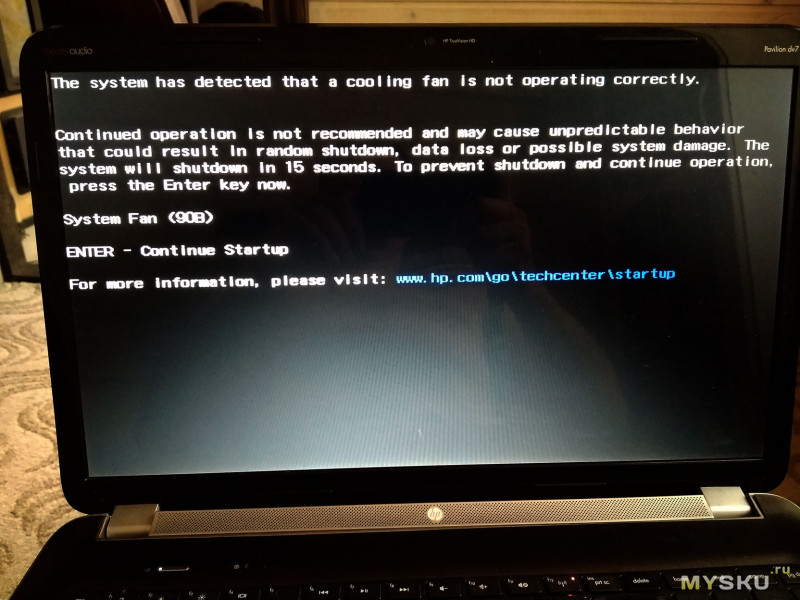
При старте у меня начала вываливаться ошибка «90b» — неисправность вентилятора системы охлаждения
— если в течении 15сек не подтвердить принудительный пуск с неисправной системой охлаждения, ноутбук просто выключается.
Часто встречается ее разновидность, «90f» — она обычно указывает на плохое охлаждение (высохла паста, или забит грязью радиатор охлаждения)
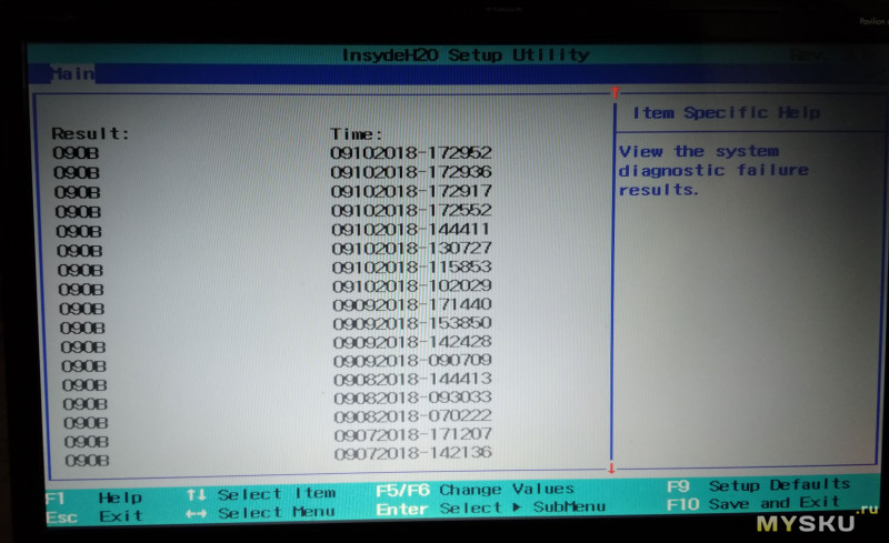
Все эти ошибки пишутся в лог. Вот например такой лог получился на моем ноутбуке, после того как «стала барахлить» система охлаждения.
При этом стали слышны периодические старт/стоп вентилятора… иногда он включался и работал нормально.
Это одна из стандартных «болячек» этих ноутбуков, а вернее контроллеров их кулеров. Через несколько лет работы они частенько начинают «глючить» именно при нагревании радиатора (через него греется корпус чипа) и при этом идет некорректное управление скоростью вентилятора (или полная его остановка). В сети попадалось даже видео эксперимента, с принудительным прогреванием этого контроллера, для доказательства виновника проблемы.
При такой ошибке, понятное дело, чистка радиаторов не дает результата. Можно попытаться смазать ось вентилятора, изредка это дает положительный результат (не всегда виноват сам контроллер), но оригинальный имеет неразборный корпус. Чтобы смазать, необходимо сверлить в корпусе отверстие (без гарантий результата) — короче, если еще учесть сложность разборки этого ноутбука, проще просто заменить кулер на новый…
Забегая вперед… конкретно в моем случае, вентилятор имел хорошую инерционность (мягкое вращение) и чистые, не забитые радиаторы, однако из 10 раз 9 выскакивала ошибка и охлаждение практически не работало (сильно грелась нижняя часть ноутбука)-проблема была именно с контроллером.
Для того, что бы заказать новый кулер, необходимо знать его Part Number. Хорошо если Вы его знаете и уверены в его правильности, иначе Вам предстоит все та же разборка/сборка 
По правде сказать, в конечном результате мне это мало помогло 

В итоге поисков нашел пару вариантов на ebay и Али. Был куплен по этой ссылке.
Внешний вид продающегося по ссылке, на текущий момент, отличается от купленного мною
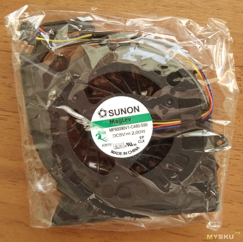
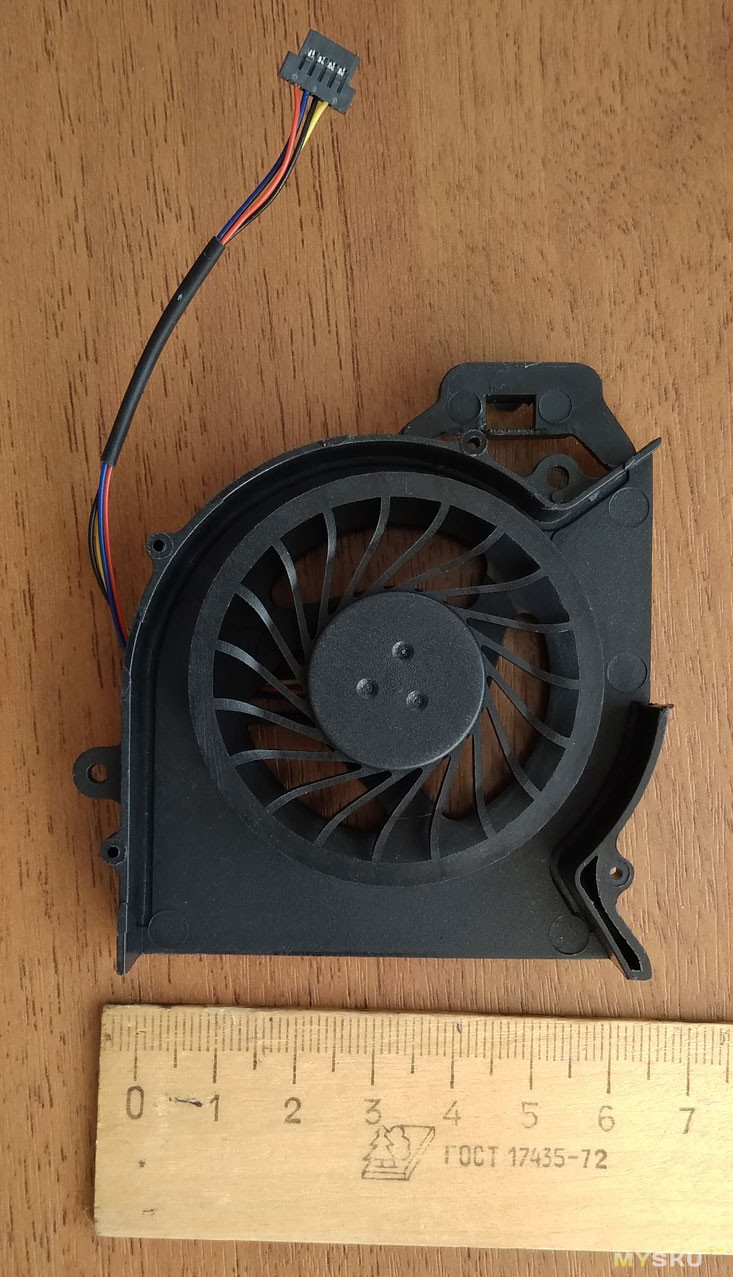
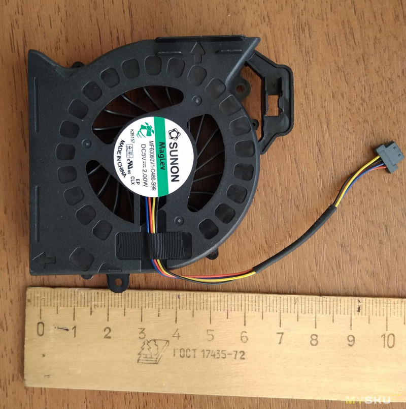
Довольно быстро приехал вот такой кулер, внешне очень похож на мой (насколько я его помнил по памяти).
Размеры
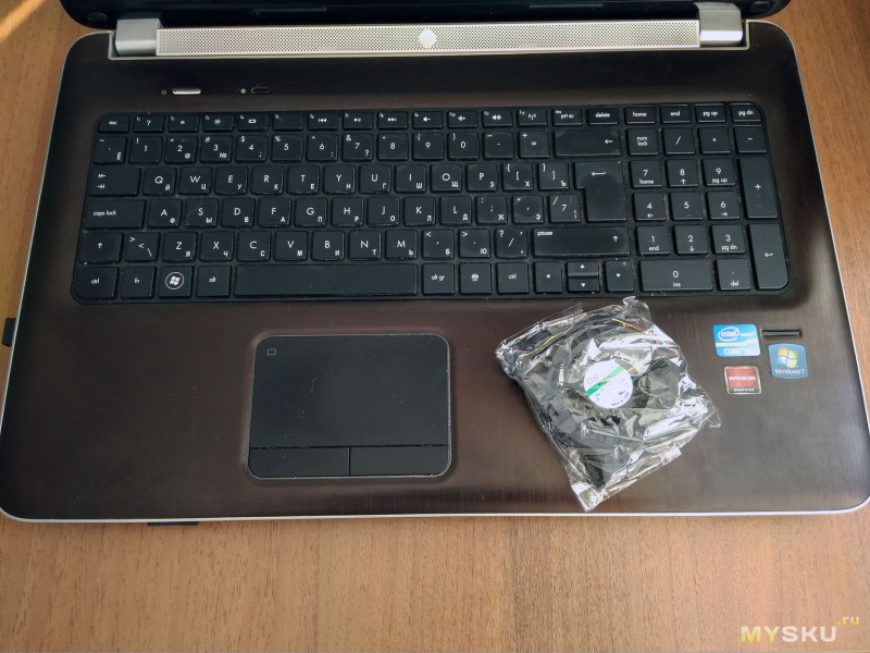
Ну что, будем менять!? 
Разборка ноутбука
Пошаговая инструкция
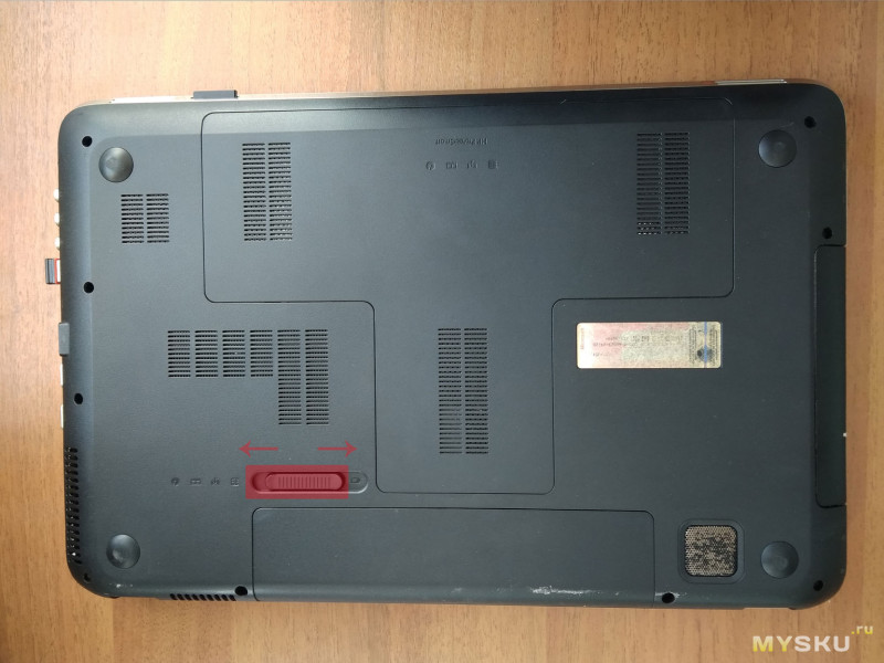
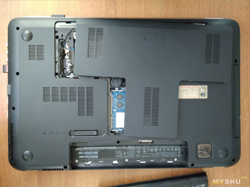
Переворачиваем ноутбук, нижней частью вверх, предварительно желательно подстелить что-нибудь мягкое под крышку.
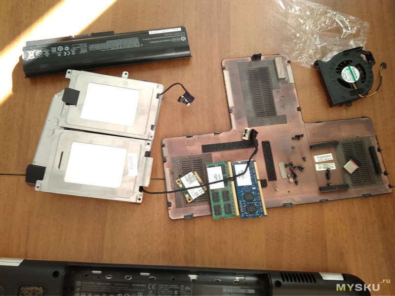
Сначала указанной защелкой разблокируем и вытаскиваем аккумулятор, затем движением в другую сторону приоткрываем отсек со всякими «вкусняшками»: жесткие диски, память, плата BT +WI-Fi…
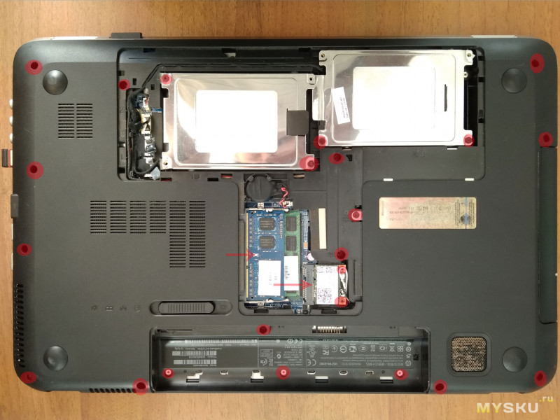
Все указанные кружочками винты необходимо открутить. Заодно вытащить платы памяти и беспроводной связи (указаны стрелками)
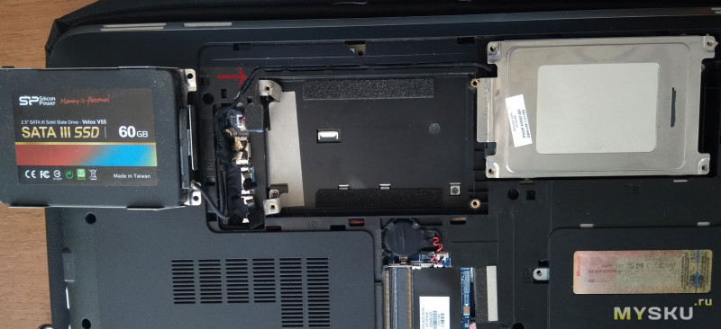
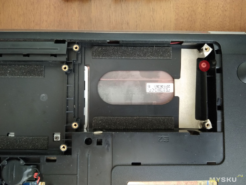
У меня два жестких дисках, но закреплены парами винтов (SSD нормально не становился).
Скорее всего у Вас будет один жесткий диск.
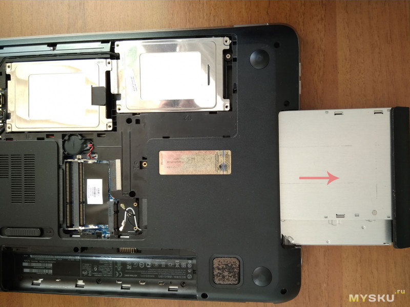
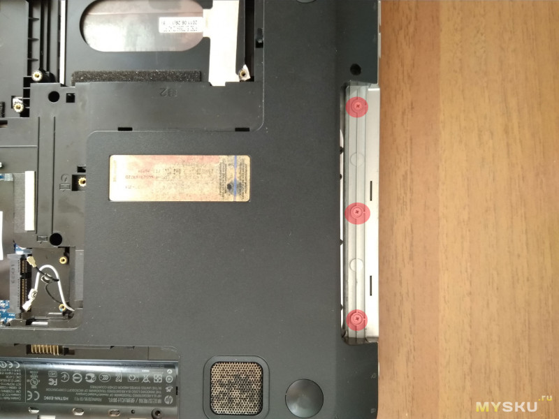
Среди откручиваемых винтов несколько отвечают за крепление CD-ROM и клавиатуры. Поэтому после их удаления можно вытаскивать CD-ROM, он держится только на разъеме.
После этого откроется доступ к еще трем винтам, их тоже надо открутить.
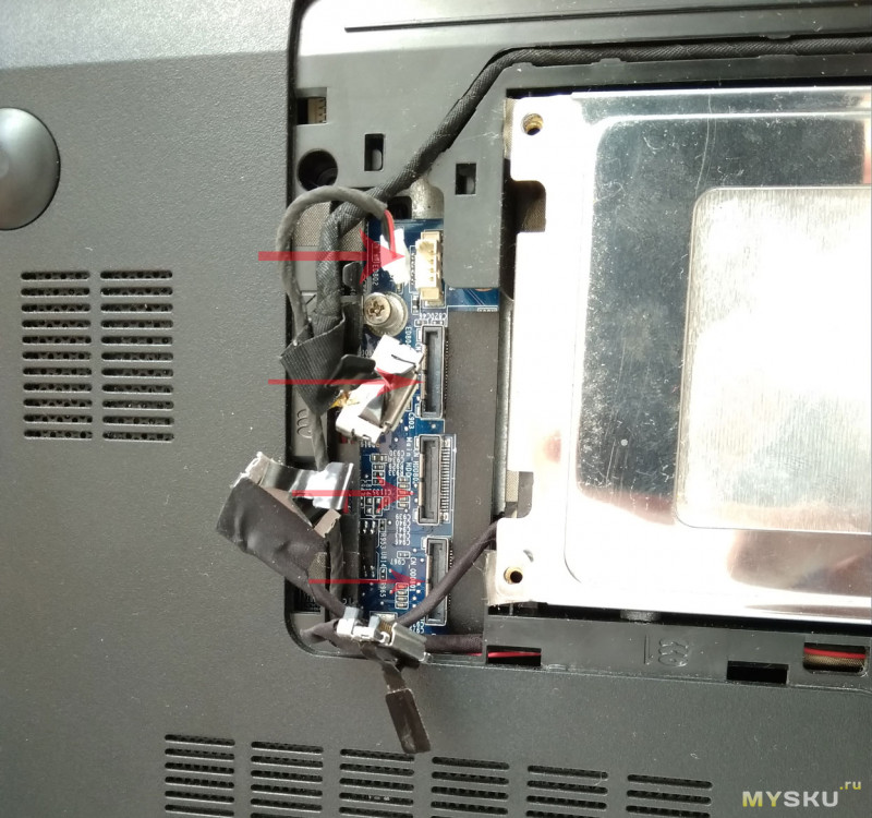
Следующим шагом отключаем шлейфы жестких дисков и CD-ROM
аккуратно вытаскиваем шлейфы -они довольно плотно «упакованы»
Появляется еще один винтик — откручиваем и его 
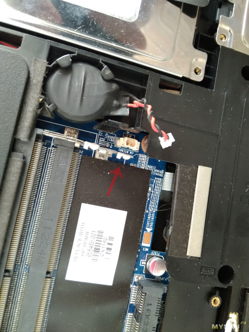
отсоединяем разъем батареи БИОС (находится возле плат памяти).
Можно не отключать (что бы потом в БИОСе настройки не восстанавливать), но тогда надо отщелкнуть батарею из посадочного места, что бы она осталась висеть на разъеме, когда начнем плату снимать.
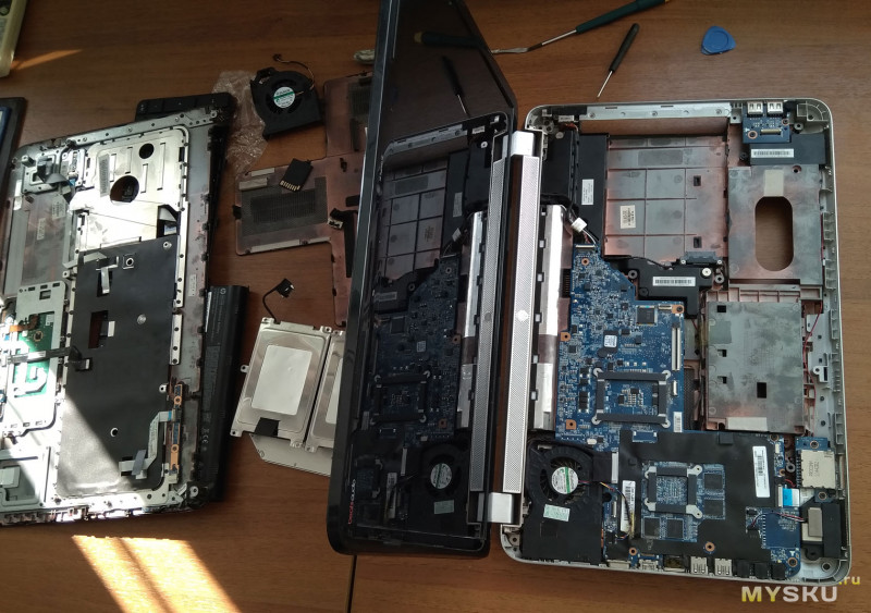
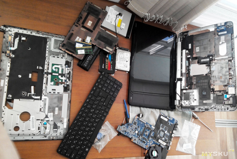
Смотрим сколько «лишних» деталей мы уже вытащили и переворачиваем ноутбук- будем теперь «курОчить» его сверху 
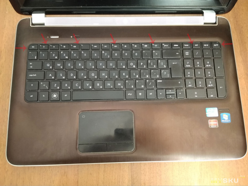
Первым делом снимает клавиатуру.
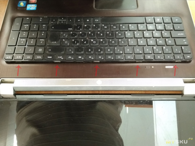
Примерно, в местах указанных стрелками, необходимо поддевать и приподнимать верхнюю часть клавиатуры.
На фото видны крепления, которыми фиксируется верхняя часть клавиатуры.
нижняя часть после этого легко вынимается, но не нужно торопиться!
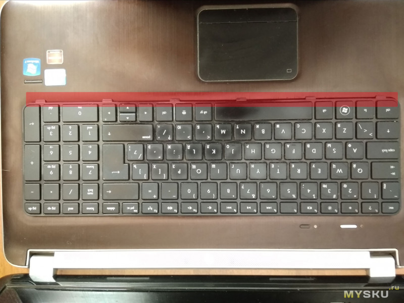
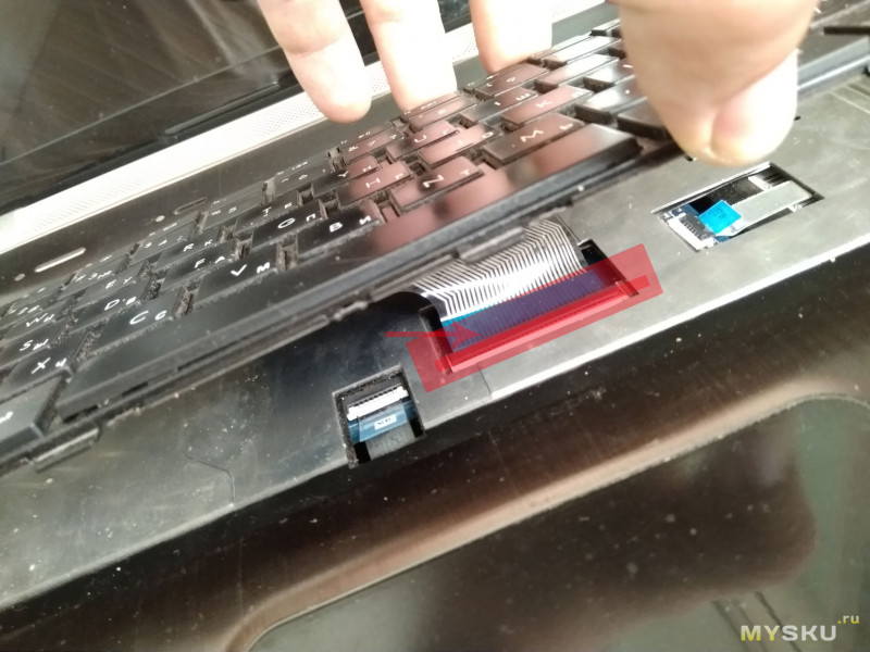
Верхнюю, освобожденную часть клавиатуры надо поднимать осторожно — под ней находится шлейф, довольно короткий. Если неосторожно потянуть клавиатуру вверх, его можно повредить!
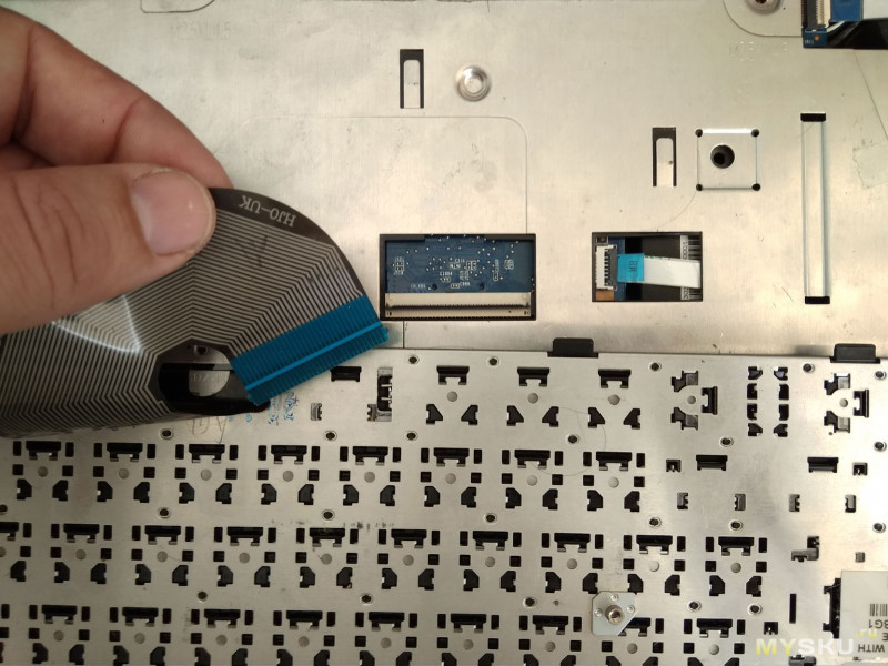
Для вытаскивания шлейфа его необходимо разблокировать защелкой (указана стрелкой и темной красной полосой) — подцепив например ногтем, защелку надо поднять вверх. После этого можно вытащить шлейф и снять клавиатуру.
Удалив клавиатуру отсоединяем подобным образом еще несколько шлейфов.
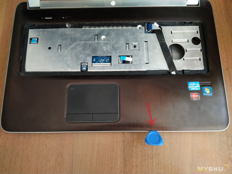
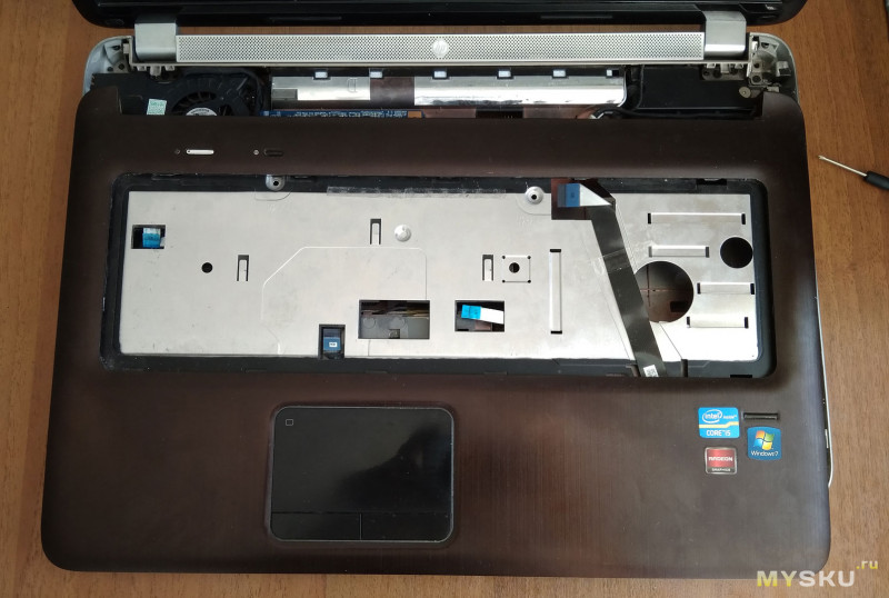
Теперь можно снять верхнюю металлическую крышку. Поддеваем ее медиатором или иным пластиковым предметом и отщелкиваем все крепления по кругу.
Крышка освобождена — можно удалить ее в сторону.
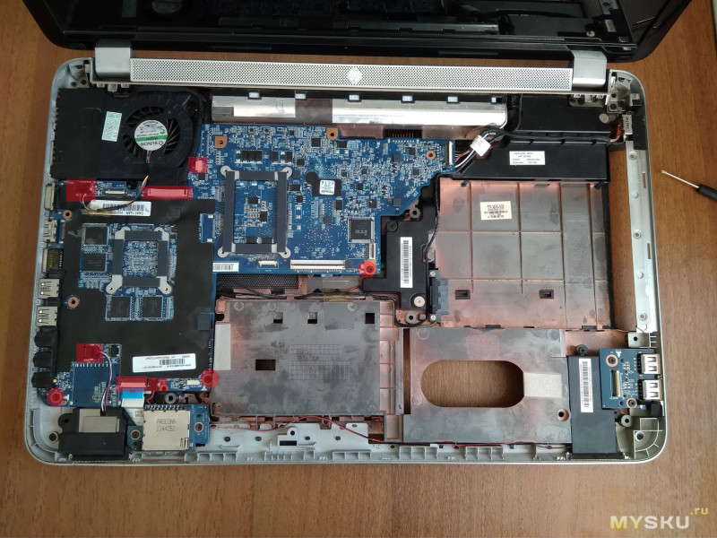
Теперь нам открывается «загадочный внутренний мир» нашего ноутбука 

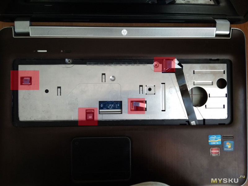
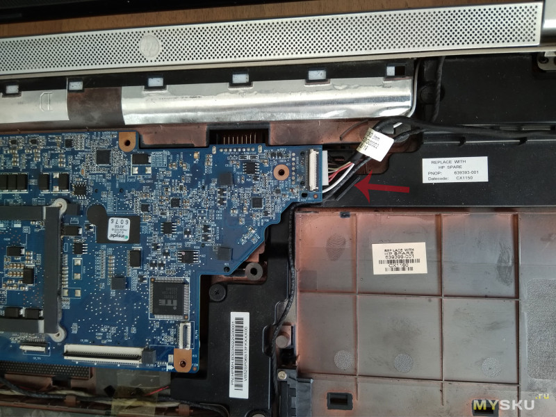
Откручиваем три винта указанных кружками и отсоединяем несколько шлейфов обозначенных красными прямоугольниками
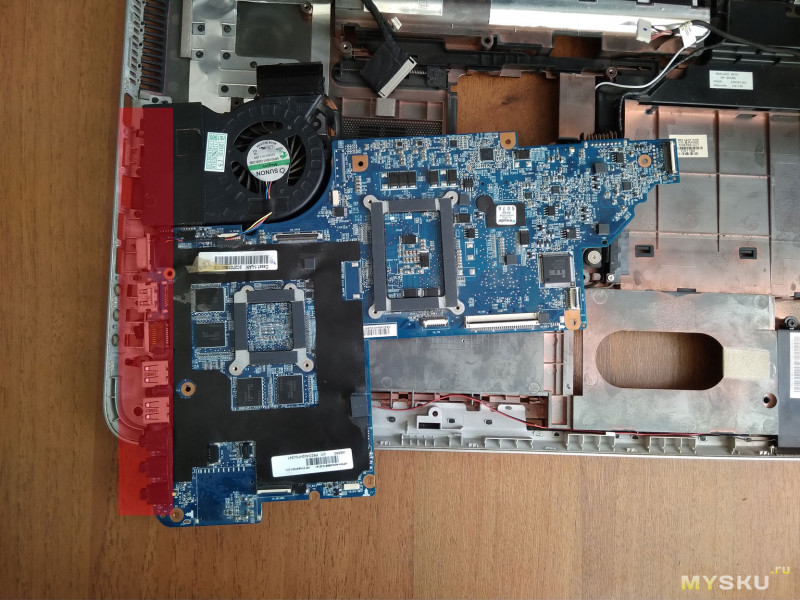
Кроме этого надо вытащить разъем справа
Ну что, мы уже близки к цели! 

Теперь надо АККУРАТНО вытащить материнскую платы, она держится в корпусе разъемами обозначенными красным цветом. Смотрите не перестарайтесь! Плата относительно хрупкая — встречал в сети жалобы на ее повреждения при неаккуратном извлечении из корпуса.
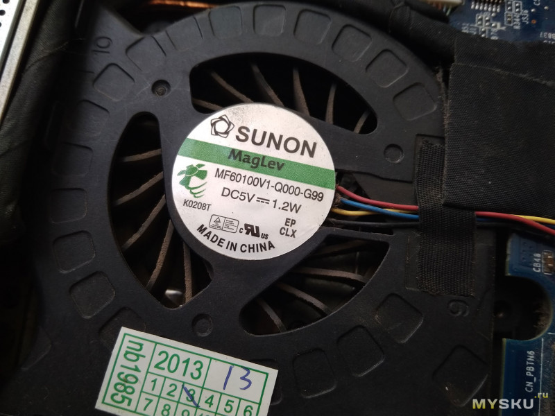
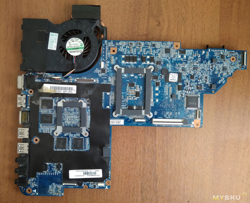
Материнка на столе, теперь можно рассмотреть маркировку кулера и заменить его на купленный.
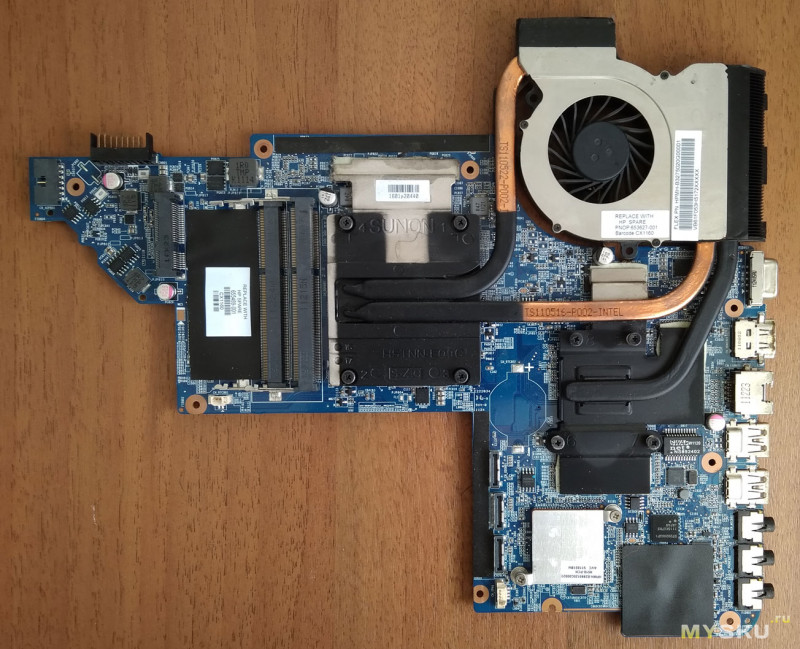
обратная сторона материнки.
При подобной разборке рекомендуется сделать профилактику радиаторам (очистить от грязи) и заменить термопасту. Я это не так давно делал, поэтому этот пункт пропускаю (фото процесса нет в наличии)
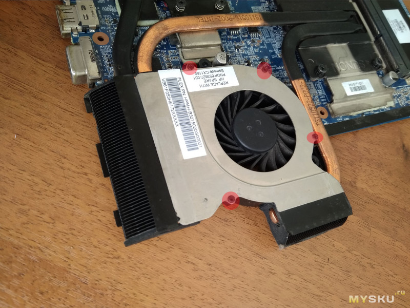
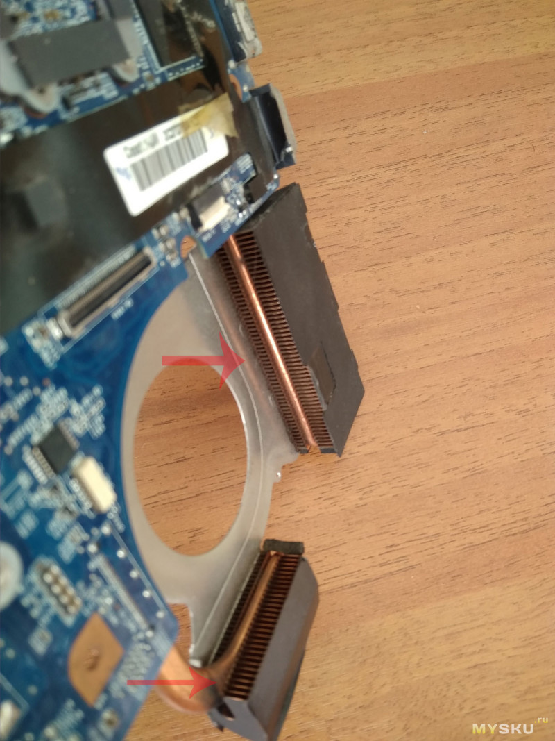
Для снятия самого кулера надо открутить еще несколько винтов 
Радиаторы, как видим, чистые — я их не слишком давно продувал.
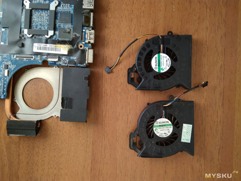
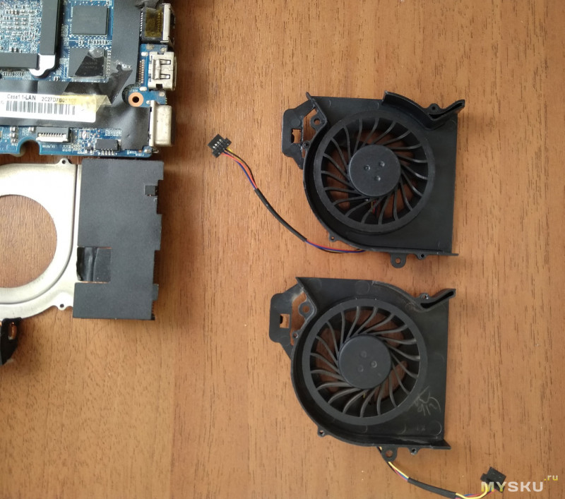
Рядом два кулера -оригинальный и купленный. На первый взгляд абсолютно одинаковые.
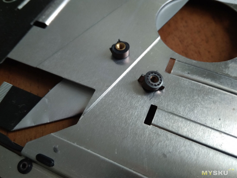
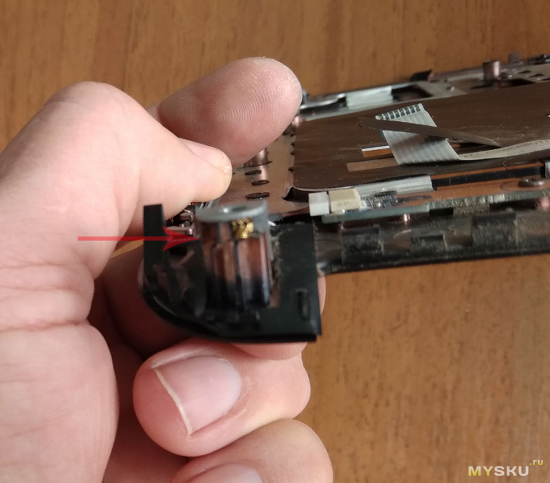
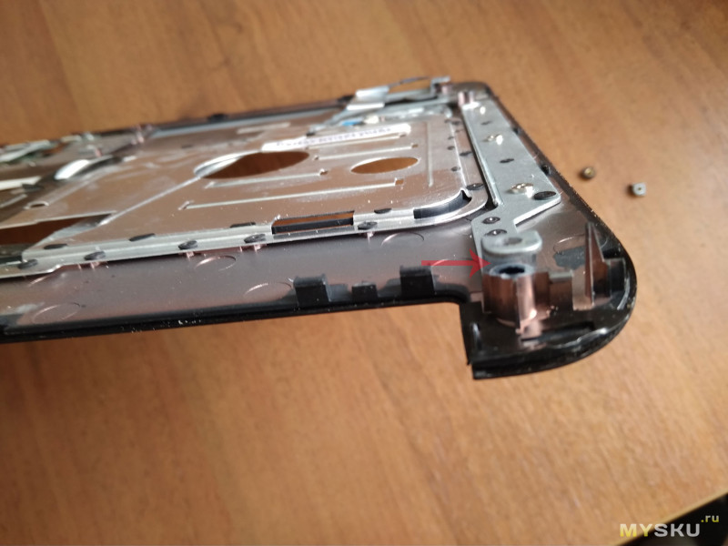
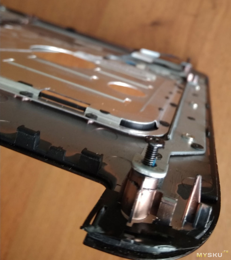
В процессе разборки, выпала пара креплений — я предполагаю уже от времени пластик стал хрупким, разбирал вроде аккуратно.
Слегка не попал в фокус, но понять откуда они я думаю возможно.
Заодно реанимируем их.
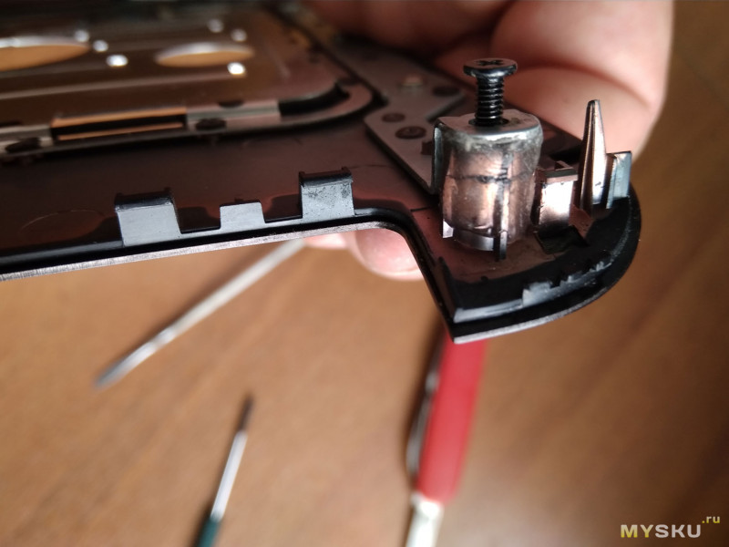
Я делаю это клеем полиморф. При высокой адгезии он имеет высокую прочность и пластичность. Всегда можно подогреть и переделать неудачно сделанное крепление. Более подробно о клее, если (вдруг) кто не сталкивался с ним, можно посмотреть, например, в этом обзоре
Сначала наживляю стойку (можно и другим клеем, имеющим большую текучесть)
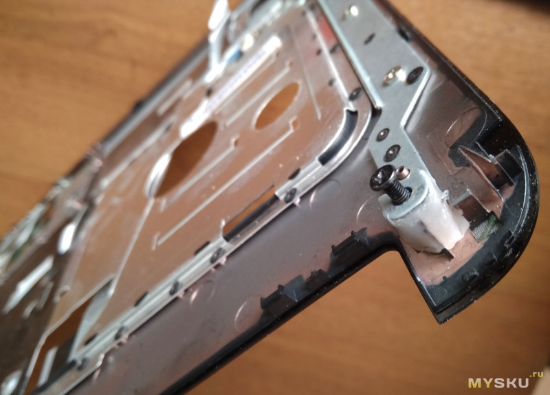
Затем разогретым полиморфом леплю необходимую форму, по необходимости подогревая его.
По мере остывания клей белеет. Это признак, что можно начинать сборку ноутбука (пока не забыли что куда вставлять и крутить;)
Сборка
думаю понятно и так — все в обратном порядке…
Из нюансов — особое внимание надо уделить фиксации шлейфов матрицы (после сборки может не заработать подсветка экрана) и шлейфам жестких дисков -иначе получите неработающую «машинку».
Шлейф клавиатуры не очень удобно вставлять и он хрупок — будьте аккуратны.
Собрали включаем :)))… и облом! 
Вроде и заработало — но нет управления вентилятором охлаждения! 
Порылся по форумам (есть нюансы настроек в БИОС и системе, а я много где успел полазить, когда плохо работало охлаждение) и в отзывах на товар (где был куплен кулер). Из отзывов понял, что
купленный кулер, хотя и 4 проводный, но это фейк!
Этот вариант не имеет управления скоростью вращения-«такое» можно было и не покупать 
ВЫВОД:
Надо СНАЧАЛА читать отзывы, а уже потом принимать решение о покупке!
День два потерпел, и полез искать другой кулер. Нашел. И уже поменял 
Ссылка на второй купленный кулер — здесь, судя по отзывам, с регулировкой оборотов должно быть все хорошо…
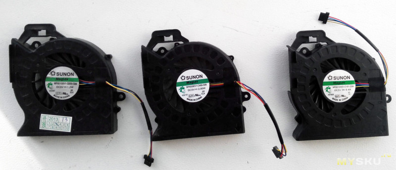
Все три кулера «в ряд»
и да, на вновь купленном
регулировка оборотов присутствует!

Итого имеем: Три раза полную разборку/сборку ноутбука (первый раз смотрел маркировку кулера) — как смог, показал, что разборка удовольствие «так себе»
Ну и вполне рабочую систему охлаждения ноутбука!
Всем удачи и хорошего настроения! 


