- Manuals
- Brands
- Honda Manuals
- Motorcycle
- CRF450X 2008
Manuals and User Guides for Honda CRF450X 2008. We have 3 Honda CRF450X 2008 manuals available for free PDF download: Service Manual, Owner’s Manual
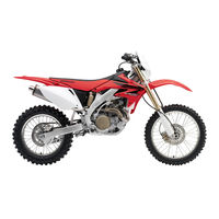
Honda CRF450X 2008 Service Manual (465 pages)
Motorcycle
Brand: Honda
|
Category: Motorcycle
|
Size: 57.18 MB
Table of Contents
-
How to Use this Manual
3
-
Contents
3
-
Symbols
4
-
Table of Contents
5
-
General Information Contents
5
-
Service Rules
6
-
Model Identification
6
-
Vehicle Identification Number
7
-
Engine Serial Number
7
-
Carburetor Identification Number
7
-
Name Plate (U.S.A.) or Safety Certification Label (Canada)
7
-
Emission Control Information Label
8
-
-
General Specifications
9
-
Lubrication System Specifications
11
-
Fuel System Specifications
11
-
Cooling System Specifications
11
-
Cylinder Head/Valves Specifications
12
-
Cylinder/Piston Specifications
12
-
Clutch/Starter Clutch/Kickstarter/Gearshift Linkage Specifications
13
-
Crankcase/ Crankshaft/ Transmission / Balancer Specifications (,Os — ·07)
13
-
CRANKCASE/CRANKSHAFT/ TRANSMISSION / BALANCER SPECIFICATIONS Iafter ·07)
14
-
Front Wheel/Suspension/Steering Specifications
15
-
Battery/Charging System Specifications
16
-
Hydraulic Brake Specifications
16
-
Ignition System Specifications
16
-
Electric Starter Specification
17
-
Lights/Meter/Switches Specifications
17
-
Engine and Frame Torque Values
18
-
Standard Torque Values
18
-
Insulator Band
21
-
Cylinder Head Side Insulator Band (After’07)
21
-
Cylinder Stud Bolt
21
-
Water Hose Clamp
21
-
Frame
22
-
Lubrication and Seal Points
25
-
Cable and Harness Routing (05-07)
29
-
Secondary Air Supply System (05 and 06 California Type, 07)
35
-
Cable and Harness Routing (after 07)
36
-
Optional Parts
41
-
-
Parts
42
-
Source of Emissions
44
-
Exhaust Emission Control System
44
-
Crankcase Emission Control System
44
-
-
Emission Control Systems
44
-
Exhaust Emission Control System (Pulse Secondary Air Injection System): 05 and 06 California Type, after 06
45
-
Prohibited Actions
45
-
Servicing the Honda
45
-
Fuel Permeation Emission Control System (after 07)
46
-
Noise Emission Control System
46
-
Rebuilt Engine
46
-
Technical Feature Contents
47
-
After the Engine Starts
48
-
Auto-Decompression System (after 07)
48
-
During Starting (When Engine Is Off)
48
-
HPSD: after 07
49
-
HPSD Characteristics
50
-
Frame/Body Panels/Exhaust System Contents
53
-
Service Information
54
-
Torque Values
54
-
Troubleshooting
54
-
Seat Installation
55
-
Seat Removal
55
-
Side Cover Removal/Installation
55
-
Radiator Shroud Removal/Installation
56
-
Center Engine Guard Removal/Installation
57
-
Front Visor Removal/Installation
57
-
Left/Right Engine Guard Removal/Installation
57
-
Front Visor Removal/Installation (after 07)
58
-
Sub-Frame Removal
58
-
Sub-Frame Installation
59
-
Fuel Tank Removal/Installation
60
-
-
Exhaust System
61
-
Muffler Removal/Installation (05-07)
61
-
Muffler Removal/Installation (after 07)
63
-
Exhaust Pipe Removal
65
-
Exhaust System Installation
66
-
Maintenance Contents
69
-
Maintenance Service Information
70
-
Maintenance Schedule (05, 06)
72
-
Maintenance Schedule (after ’06)
73
-
-
Competition Maintenance Schedule
74
-
Additional Items Requiring Frequent Replacement
75
-
Fuel Line
76
-
Fuel Strainer Screen
76
-
Throttle Operation
77
-
Air Cleaner
78
-
Hot Start
78
-
Crankcase Breather
79
-
Spark Plug Inspection
80
-
Spark Plug Removal
80
-
-
Radiator Coolant
81
-
Cooling System
82
-
Secondary Air Supply System (05 and 06 California Type, after 06)
82
-
Valve Clearance Inspection
83
-
Valve Clearance/Decompressor System
83
-
Valve Clearance Adjustment
84
-
Decompressor Clearance Inspection/Adjustment (05-07)
86
-
Decompressor System (after 07)
87
-
Engine Oil/Oil Filter
87
-
Oil Level Inspection
87
-
Engine Oil and Filter Change
88
-
-
Engine Idle Speed
90
-
Oil Level Inspection
90
-
Transmission Oil
90
-
Transmission Oil Change
91
-
Drive Chain
92
-
Drive Chain Adjustment
92
-
Drive Chain Cleaning and Lubrication
92
-
Drive Chain Slack Inspection
92
-
Drive Chain Replacement
93
-
-
Drive Chain Slider
95
-
Drive Chain Roller
96
-
Drive/Driven Sprocket
96
-
Brake Fluid
97
-
Fluid Filling
97
-
Fluid Level Inspection
97
-
-
Brake Pad Wear
98
-
Brake System
98
-
Lever Position Inspection
98
-
Brake Pedal Height
99
-
-
Clutch System
99
-
Headlight Aim
99
-
Control Cables
100
-
Exhaust Pipe/Muffler
101
-
Exhaust System Inspection
101
-
Spark Arrester Inspection/Cleaning
101
-
Spark Arrester Removal
101
-
Front Suspension Inspection
102
-
Sidestand Inspection
102
-
Spark Arrester Installation
102
-
Rear Suspension Inspection
103
-
-
Swingarm/Shock Linkage
103
-
Nuts, Bolts, Fasteners
104
-
Wheels/Tires
104
-
Steering Head Bearings
105
-
Lubrication System Contents
107
-
Lubrication System Diagram
108
-
Lubrication System Service Information
109
-
Oil Strainer Removal/Inspection
110
-
Oil Strainer Installation
111
-
Pressure Relief Valve Removal/Inspection
111
-
Oil Jet Removal/Inspection
112
-
Pressure Relief Valve Installation
112
-
Oil Jet Installation
113
-
Oil Pump Disassembly
113
-
Oil Pump Inspection
113
-
Oil Pump Assembly
114
-
Fuel System Contents
115
-
Fuel System Component Location
116
-
Fuel System Service Information
117
-
Carburetor Adjustment
120
-
Idle Mixture and Idle Speed
120
-
Air Cleaner Housing Removal
121
-
Air Cleaner Housing Installation
123
-
Carburetor Removal
125
-
Carburetor Disassembly
127
-
Jet Needle/Throttle Valve
127
-
Choke Knob/Throttle Sensor
128
-
Accelerator Pump/Float/Jets
129
-
Carburetor Assembly
132
-
Carburetor Installation
138
-
Throttle Position Sensor Replacement
140
-
Best Idle (05, 06: 49 States and Canada Type Only)
141
-
Pilot Screw Adjustment
141
-
Idle Drop Procedure (05 and 06 California Type, 07, after 07)
142
-
System Inspection
143
-
Pair Check Valve Ispection
144
-
Pair Control Valve Removal/Installation
144
-
Air Supply Pipe Removal/Installation
145
-
Cooling System Contents
147
-
System Flow Pattern
148
-
Cooling System Service Information
149
-
Cooling System Troubleshooting
150
-
Coolant (Hydrometer Test)
151
-
Coolant Gravity Chart
151
-
System Testing
151
-
Coolant Replacement Preparation
152
-
Radiator Cap/System Pressure Inspection
152
-
Replacement/Air Bleeding
153
-
Radiator Removal/Installation
154
-
Mechanical/Oil Seal Inspection
155
-
Radiator Reserve Tank Removal/Installation
155
-
Water Pump
155
-
Water Pump Removal
156
-
Bearing/Mechanial Seal/Oil Seal Replacement
158
-
Water Pump Installation
159
-
Engine Removal/Installation Contents
163
-
Engine Component Location
164
-
-
Engine Removal
164
-
Engine Service Information
165
-
Drive Sprocket Installation
166
-
Drive Sprocket Removal
166
-
Engine Removal
167
-
-
Engine Installation
170
-
Drive Sprocket
171
-
Cylinder Head/Valves Contents
173
-
Cylinder Head/Valves Component Location
174
-
Cylinder Head/Valves Service Information
175
-
Cylinder Compression Test
179
-
Cylinder Head Cover Removal
179
-
Camshaft Removal (05-07)
180
-
Camshaft Disassembly
182
-
Camshaft Inspection
183
-
Camshaft Assembly
186
-
Camshaft Removal (after 07)
188
-
Rocker Arm Inspection
191
-
Rocker Arm Shaft Inspection
191
-
Cam Sprocket/Decompressor Weight/Spring Inspection
192
-
Decompressor Shaft/Plunger Inspection
192
-
Camshaft Holder Bearing Replacement
193
-
Camshaft Holder Inspection
193
-
Valve Lifter Inspection
193
-
Camshaft Holder Bearing Assembly
194
-
Cylinder Head Removal
196
-
Cam Chain Tensioner/Cam Chain Guide Removal
197
-
Cam Chain Tensioner/Cam Chain Guide Inspection
198
-
Cam Chain Tensioner/Cam Chain Guide Installation
198
-
Cylinder Head Disassembly
199
-
Cylinder Head Inspection
200
-
Valve Spring Inspection
200
-
Valve/Valve Guide Inspection
200
-
Valve Guide Replacement
201
-
Valve Seat Inspection/Refacing
202
-
Valve Seat Refasing
203
-
Cylinder Head Assembly
205
-
Cylinder Head Installation
208
-
Camshaft Installation (05-07)
209
-
Camshaft Installation (after 07)
211
-
Cylinder Head Cover Installation
214
-
Cylinder/Piston Contents
217
-
Cylinder/Piston Component Location
218
-
Cylinder/Piston Service Information
219
-
Cylinder/Piston Troubleshooting
220
-
Cylinder Removal
221
-
Cylinder Inspection
222
-
-
Piston Removal
222
-
Piston Ring Removal
222
-
Piston/Piston Ring Inspection
223
-
Cam Chain Tensioner Lifter Inspection
224
-
Connecting Rod Inspection
224
-
-
Piston Installation
225
-
Piston Ring Installation
225
-
Cylinder Installation
226
-
Clutch/Starter Clutch/Kickstarter/Gearshift Linkage Contents
229
-
Clutch/Starter Clutch/Kickstarter/Gearshift Linkage Component Location
230
-
Clutch/Starter Clutch/Kickstarter/Gearshift Linkage Service Information
231
-
Right Crankcase Cover Removal
233
-
Right Crankcase Cover Installation
234
-
Clutch Removal
235
-
Clutch Spring Inspection
237
-
Clutch Center Inspection
238
-
Clutch Discs Inspection
238
-
Clutch Lifter/Needle Bearing Inspection
238
-
Clutch Plates Inspection
238
-
Clutch Lifter Lever Inspection
239
-
Clutch Outer Guide Inspection
239
-
Clutch Outer Inspection
239
-
Needle Bearing Inspection
239
-
Clutch Installation
240
-
Kickstarter Disassembly
243
-
Kickstarter Inspection
243
-
Kickstarter Removal
243
-
Kickstarter Assembly
245
-
Kickstarter Installation
246
-
Starter Clutch Removal
247
-
Starter Clutch Disassembly/Inspection
248
-
Starter Clutch Assembly
250
-
Starter Clutch Installation
251
-
Gearshaft Linkage Removal
252
-
Gearshaft Linkage Inspection
253
-
Gearshift Spindle Inspection
253
-
Ratchet Pawl Inspection
253
-
Gearshift Linkage Installation
254
-
Alternator Contents
257
-
Alternator Component Location
258
-
Alternator Service Information
259
-
-
Stator
259
-
Left Crankcase Cover Removal
260
-
Flywheel Removal
261
-
Stator Removal
261
-
Flywheel Installation
262
-
-
Left Crankcase Cover Installation
262
-
Crankcase/Crankshaft/Transmission/Balancer Contents
265
-
Crankcase/Crankshaft/Transmission/Balancer Component Location
266
-
Crankcase/Crankshaft/Transmission/Balancer Component Service Information
267
-
Crankcase/Crankshaft/Transmission/Balancer Troubleshooting
271
-
Balancer/Gear Balancer Inspection
272
-
Balancer/Gear Balancer Installation
272
-
Balancer/Gear Balancer Removal
272
-
-
Crankcase Separation
274
-
Transmission Disassembly
275
-
Bushing Inspection
276
-
Gear Inspection
276
-
Mainshaft/Countershaft Inspection
277
-
Shift Fork Inspection
277
-
Shift Fork Shaft Inspection
277
-
-
Crankshaft Removal
278
-
Shift Drum Inspection
278
-
Transmission Bearing Inspection
278
-
Crankshaft Inspection
279
-
-
Crankcase Bearing Replacement
280
-
Crankcase Bearing/Oil Seal Location
280
-
Crankshaft Bearing
280
-
Left Crankcase
282
-
Transmission/Balancer Bearings
282
-
Right Crankcase
284
-
-
Crankshaft Installation
285
-
Transmission Assembly
286
-
Countershaft (05-07)
287
-
Mainshaft (after 07)
287
-
Countershaft (after 07)
288
-
Transmission Installation
288
-
-
Crankcase Assembly
289
-
Front Wheel/Suspension/Steering Contents
291
-
Front Wheel/Suspension/Steering Component Location
292
-
Front Wheel/Suspension/Steering Service Information
294
-
Front Wheel/Suspension/Steering Troubleshooting
297
-
Axle Inspection
298
-
Front Wheel Removal
298
-
Front Wheel Disassembly
299
-
Wheel Bearing Inspection
299
-
Wheel Rim Inspection
299
-
Front Wheel Assembly
300
-
Front Wheel Installation
302
-
Fork Removal
303
-
Fork Disassembly
305
-
Outer Tube and Slider Disassembly
307
-
Fork Damper Disassembly
308
-
Fork Cap Inspection
309
-
Fork Center Bolt Inspection
309
-
Slider/Outer Tube Inspection
309
-
Bushing/Back-Up Ring Inspection
310
-
Fork Damper Inspection
310
-
Fork Spring Inspection
310
-
Fork Assembly
311
-
Outer Tube and Slider Assembly
311
-
Fork Damper Refilling/Assembly
312
-
Fork Damper Operation Inspection
315
-
Fork Damper Instllation/Preparation
316
-
Fork Damper Installation
317
-
Fork Installation
320
-
Oil Capacity Adjustment
320
-
Standard Position
321
-
Handlebar Removal
322
-
Handlebar Installation
324
-
-
After ’07
327
-
HPSD (Honda Progressive Steering Damper): after 07 Removal/Installation
328
-
HPSD (Honda Progressive Steering Damper): after 07 Inspection
329
-
Spherical Bearing Replacement
329
-
HPSD (Honda Progressive Steering Damper): after 07 Disassembly
330
-
HPSD Assembly
332
-
Steering Stem Removal
337
-
Bearing Replacement
338
-
Steering Stem Installation
340
-
Clutch Lever Removal/Installation
342
-
Rear Wheel/Suspension Contents
343
-
Rear Wheel/Suspension Component Location
344
-
Rear Wheel/Suspension Service Information
345
-
Rear Wheel/Suspension Troubleshooting
349
-
Rear Wheel Removal
350
-
Rear Wheel Disassembly
351
-
Rear Wheel Assembly
352
-
Rear Wheel Installation
355
-
Shock Absorber Removal
356
-
Bladder Replacement
357
-
Shock Absorber Disassembly
357
-
Damper Disassembly
360
-
Damper Rod Disassembly
362
-
Piston Ring Replacement
362
-
Damper Rod Inspection
364
-
Rod Guide Case Inspection
364
-
Damper Assembly
365
-
Shock Absorber Installation
371
-
Shock Linkage Removal
372
-
Shock Absorber Inspection
374
-
Shock Arm Needle Bearing
374
-
Shock Link Needle Bearing
376
-
Swingarm Removal
378
-
Swingarm Disassembly
380
-
Swingarm Assembly
381
-
Swingarm Installation
382
-
Hydraulic Brake Contents
385
-
Hydraulic Brake Component Location
386
-
Hydraulic Brake Service Information
387
-
Hydraulic Brake Troubleshooting
389
-
Brake Fluid Replacement/Air Bleeding
390
-
Brake Fluid Filling/Air Bleeding
391
-
Brake Pad Replacement
394
-
-
Brake Pad/Disc
394
-
Brake Disc Inspection
395
-
Front Master Cylinder Disassembly
396
-
Front Master Cylinder Removal
396
-
Front Master Cylinder Inspection
397
-
Front Master Cylinder Assembly
398
-
Front Master Cylinder Installation
398
-
Rear Master Cylinder Disassembly
399
-
Rear Master Cylinder Removal
399
-
Rear Master Cylinder Assembly
400
-
Rear Master Cylinder Inspection
400
-
Rear Master Cylinder Installation
401
-
Front Brake Caliper Disassembly
402
-
Front Brake Caliper Removal
402
-
Front Brake Caliper Assembly
403
-
Front Brake Caliper Inspection
403
-
Front Brake Caliper Installation
404
-
Rear Brake Caliper Removal
404
-
Rear Brake Caliper Disassembly
405
-
Rear Brake Caliper Inspection
406
-
Rear Brake Caliper Assembly
407
-
Rear Brake Caliper Installation
407
-
Brake Pedal Installation
408
-
Brake Pedal Removal
408
-
Battery/Charging System Contents
411
-
Battery/Charging System Component Location
412
-
Battery/Charging System Diagram
412
-
Battery/Charging System Service Information
413
-
Battery/Charging System Troubleshooting
415
-
Battery Charging (USA Only)
416
-
Battery Removal/Installation
416
-
Battery Testing
416
-
Voltage Inspection
416
-
-
Charging System Inspection
417
-
Charging Voltage Inspection
417
-
Current Leakage Inspection
417
-
Alternator Charging Coil Inspection
418
-
Regulator/Rectifier Removal/Installation
418
-
Regulator/Rectifier System Inspection
418
-
Ignition System Contents
419
-
Ignition System Component Location
420
-
Ignition System System Diagram
420
-
Ignition System Service Information
421
-
Ignition System Troubleshooting
422
-
Ignition Coil Primary Peak Voltage
423
-
Ignition System Inspection
423
-
Exciter Coil Resistance
424
-
Ignition Pulse Generator Peak Voltage
424
-
Ignition Coil Inspection
425
-
Ignition Control Module (ICM) Removal/Installation
425
-
-
Ignition Timing
426
-
Ignition Coil Removal/Installation (after 07)
426
-
Ignition Coil Removal/Installation (05-07)
426
-
Throttle Position Sensor Inspection
427
-
Electric Starter Contents
429
-
Electric Starter Component Location
430
-
Electric Starter System Diagram
430
-
Electric Starter Service Information
431
-
Electric Starter Troubleshooting
432
-
Starter Motor Removal
434
-
Starter Motor Disassembly/Inspection
434
-
Starter Motor Assembly
438
-
Ground Line
441
-
Starter Relay Switch Inspection
441
-
Starter Motor Installation
441
-
Starter Relay Switch Removal/Installation
442
-
Power Input Line
442
-
Operation Check
442
-
Lights/Meter/Switches Contents
443
-
Lights/Meter/Switches Component Location
444
-
Lights/Meter/Switches Service Information
445
-
Headlight Bulb Replacement
446
-
Headlight Removal/Installation (05-07)
447
-
Headlight Removal/Installation (after 07)
448
-
Tail Light Inspection
448
-
Tail Light Removal/Installationn
448
-
Engine Stop Button Inspection
449
-
Clutch Switch Inspection
450
-
Clutch Switch Removal/Installation
450
-
Starter Switch Inspection
451
-
Tripmeter Removal/Installation
452
-
Wiring Diagram
454
-
Troubleshooting Contents
455
-
Engine Does Not Start or Is Hard to Start
456
-
Engine Lacks Power
457
-
Poor Performance at Low and Idle Speed
459
-
Poor Performance at High Speed
460
-
Poor Handling
461
-
Index
463
-
Advertisement
Honda CRF450X 2008 Owner’s Manual (64 pages)
Brand: Honda
|
Category: Water Pump
|
Size: 1.22 MB
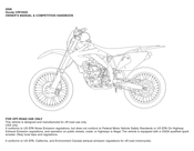
Honda CRF450X 2008 Owner’s Manual (5 pages)
Brand: Honda
|
Category: Motorcycle
|
Size: 0.14 MB
Advertisement
Advertisement
Related Products
-
Honda CRF450X 2007
-
Honda CRF450X 2006
-
Honda CRF450X 2010
-
Honda CRF450X 2009
-
Honda CRF450X 2011
-
Honda CRF450X 2005
-
Honda CRF450X 2012
-
Honda CRF450X 2017
-
Honda CRF450X 2020
-
Honda CRF450X 2021
Honda Categories
Motorcycle
Automobile
![]()
Lawn Mower
Offroad Vehicle
Engine
More Honda Manuals
![]()
4-я Красноармейская, 2А
Санкт-Петербург, 190005
Email: info@lenmoto.ru
Телефон: +7 (921) 930-81-18
Телефон: +7 (911) 928-08-06
Компания ЛенМото
Запчасти, аксессуары, экипировка, тюнинг для мотоциклов, скутеров, квадроциклов, снегоходов, багги, гидроциклов, катеров и лодочных моторов.
Подпишитесь на наши новости
Подписаться
(Ocr-Read Summary of Contents of some pages of the Honda CRF450X 2005 Document (Main Content), UPD: 27 April 2023)
-
318, FRONT WHEEL/SUSPENSION/STEERING Do not over- lIghten the vISe on the 8Jt/e holder, Check / he push rod Inst/JllallOn by turning rhe push rod fight and I6fr 14-28 Set the axle holder of the slider in a vise with a piece of weod or soh jaws to avoid damage. Push the fork damper out of the lock nut from sl ider , while install the piston base or mechanic…
-
217, ‘— .- u \ COMPONENT LOCATION ···· .. · .. · .. ·· ······ ···· 10-2 SERVICE INFORMATION ························· 10-3 TROUBLESHOOTING ……………. · ………….. 10-4 CYLINDER REMOVAL .. .. · .. .. .. ……………… · 10-5 10. CYLINDER/PISTON PISTON REMOVAL …… .. …. .. ……………….. 10-6 PISTON INSTALLATION ………………… …. . 10-9 CYLINDER INSTALLATION …. …… …….. .. 10 …
-
441, Honda CRF450X 2005 ‘- INSTALLATION Install the starter motor onto the crankcase. Install and tighten the starter motor mounting bolt. Install the starter motor cable and terminal nut onto the motor terminal. Tighten the nut securely. Install the rubber cap over the motor terminal prop — erly. Install the cylinder (page 10-1 0). STARTER RELAY SWITCH INSPECTION Remove the left side cover (page 3-3 ), Shift the transmission into neutral. Pull the …
-
362, REAR WHEEL/SUSPENSION 15-20 PISTON RING REPLACEMENT Inspect the piston ring. If the piston ring is damaged, cut th e piston ring and replace it along with new O-rings. O-RINGS PISTON RING Apply fork oil to new a’rings and piston ring. ~~~;=;~~~ =~~~ ~~;;;; ~;=,;~~ ~ Place the piston ring guide attachment over the pis- 1 S!I ~ .. PISTON RING ton and install new Q-rings and piston ring into IIIijjjIII place by hand. .. TOOL :…
-
48, TECHNICAL FEATURE AUTO-DECOMPRESSION SYSTEM (After ’07) DURING STARTING (WHEN ENGINE IS OF F ): DECOMPRESSOR PLUNGER CAMSHAFT DEC:OM I PRE’SS,)R SHAFT )AI ROCKER ARM AFTER THE ENG I NE STARTS: VALVE DEC:O.,PRESE:OR WEIGHT DURING STARTING (WHEN ENGINE IS OFF) The decompressor plunger protrudes from the exhaust cam lobe, and depresses the exhaust valve via the rocker arm . The exhaust valve is slightly opened, end releases some cylinder comp…
-
257, 12. ALTERNATOR COMPONENT LOCATION ··· …. ················· 12 -2 STATOR ………………………………………. · …. · 12 -5 SERVICE INFORMATION …. · .. · …… · …. · …. ·12 -3 FLyWHEEL …… · …….. · ………… · …. · ………….. 12-5 LEFT CRANKCASE COVER REMOVAL .. · 12-4 LEFT CRANKCASE COVER INSTALLATION …. …………………… · …. · …… 12-6 ( ~ 12-1 …
-
340, FRONT WHEEL/SUSPENSION/STEERING 14-50 Temporarily install the stem nut to avoid damaging the stee ring stem threads. Remove the lower tapered roller bearing and dust seal from the steering stem. Apply urea based mUlti-purpose grease with extreme pressure to the dust seal lips. Install a new dust seal. Install the lower bearing using a hydraulic press and the special tool …
-
97, Honda CRF450X 2005 BRAKE FLUID I NOTICE Spilled fluid can damage painted, plastic or rubber parts. Place a rag over these parts whenever the system is serviced. • Do not mix different types of fluid, as they are not compatible with each other. • Do not allow foreign material to enter the system when filling the reservoir. FLUID LEVEL INSPECTION When the fluid level is low, check the brake pads for …
-
82, MAINTENANCE COOLING SYSTEM Remove the fuel tank (page 3-8). Remove the radiator grill (page 7- B), Check the radiator air passages f or clogging or dam — age. Straighten bent fins, and remove insects, mud or other obstructions w it h compressed air or l ow water pressur e. Replace the radiator if the ai r flow is restricted over more than 20 % of the radiating s urf ace. Inspect the radiator hoses for cracks or deteriora- L ::;;;…
-
367, Honda CRF450X 2005 l Stake the end of the damper rod in three places as shown, to the end nut. Coat the damper rod with Pro Honda HP Fork Oi l 5W or equivalent. Check the rod guide case by sliding it up and down fully to be sure there is no restriction. Coat the damper case inner surface, piston ring and O-ring with Pro Honda HP Fork Oil 5W or equivalent, and insert the damper rod assembly carefully.…
-
8, GENERAL INFORMATION The Vehicle Emission Control Information label is attached on the rear ’05 — ’06 California type, ’07 U.S. A. : fender (‘ 05 — ’06 California type, ‘ 07 U.S.A.!. /’ DO ~ » ~:/~~ EMISSION CDNTROllNFORMATION LABEL The Vehicle Emission Control Information label is attached on the rear After ’07 U.S.A. and Canada : fender (After ’07 U.S.A. and Canada ). ;:…- /ada type o nly ~»- ~ ~ V ~ …
-
254, CLUTCH/ STARTER CLUTCH/KICKSTARTER/GEARSHIFT LINKAGE 11-26 INSTALLATION Install the drum pin into the hole on the shift drum. Install the return spring, washer and stopper arm and tighten the gearshift stopper arm bolt to the specified torque. TORQUE: 12 N’m (1.2 kgf·m , 9 Ibf.ft) Check the gearshift stopper arm for proper opera- tion. M ove the stopper arm out …
-
396, HYDRAULIC BRAKE Measure the brake di sc warpage with a dial indica- J;5 _ ’07 …. tor. SERVICE LIMIT: 0.15 mm (0.006 in) Check the wheel bearings fo r excessive play. if the wa rpage exceeds the service lim it . __ —:; t’ Replace the brake disc if the wheel bearings are no(- mal. _ ….,~l FRONT MASTER CYLINDER REMOVAL Drain the front br ake hydraulic system (page 16-6). When removing the Remove the brake hose oil bolt, seal…
-
399, L Align the brake hose eyelet between the stoppers. Install the brake hose eyelet with the oi l bolt and new sealing washers . Tighten the brake hose oi l bolt to the specified torque . TORQUE: 34 N·m 13 .5 kg f·m, 25 Ibf· ft ) Fill and bleed the fr ont brake hydraulic system (page 16- 7) . REAR MASTER CYLINDER REMOVAL Drain the rear brake hydraulic system (page 16-6). Remove the brake pedal (page 16-24). Vv…
-
151, £ «-. SYSTEM TESTING COOLANT (HYDROMETER TEST) Make sure the engine is cool, remove the radiator cap. Te st the coolant specific gravity using a hydrome- ter. STANDARD COOLANT CONCENTRATION: 1 : 1 Look for contamination and replace the coolant if Io…..,;ol: … — necessary. COOLANT GRAVITY CHART COOLING SYSTEM 7-5
…
CT110
User Manual

Honda CT110 User’s Manual,
10 pages
2005 CB900F
User Manual
Honda 2005 CB900F User’s Manual,
18 pages
2006 ST1300/A
User Manual
Honda 2006 ST1300/A User’s Manual,
28 pages
VFR750F 1995
User Manual
Honda VFR750F 1995 User’s Manual,
130 pages
CBR600RR-ABS
User Manual

Инструкция по эксплуатации HONDA CBR600RR-ABS,
166 pages
CRF150RE (2006)
User Manual
Инструкция по эксплуатации HONDA CRF150RE (2006),
153 pages
FMX650
User Manual
Инструкция по эксплуатации HONDA FMX650,
126 pages
VTX1800
User Manual
Инструкция по эксплуатации HONDA VTX1800,
120 pages
GL1800A (2006)
User Manual
Инструкция по эксплуатации HONDA GL1800A (2006),
196 pages
VTR1000
User Manual
Инструкция по эксплуатации HONDA VTR1000,
138 pages
CBR1000RR-ABS
User Manual
Инструкция по эксплуатации HONDA CBR1000RR-ABS,
171 pages
TRX450R (2005-2011)
User Manual
Инструкция по эксплуатации HONDA TRX450R (2005-2011),
210 pages
CBR600F (2004)
User Manual
Инструкция по эксплуатации HONDA CBR600F (2004),
147 pages
TRX420FA (2009-2011)
User Manual
Инструкция по эксплуатации HONDA TRX420FA (2009-2011),
234 pages
XL1000VA Varadero
User Manual
Инструкция по эксплуатации HONDA XL1000VA Varadero,
154 pages
CBR600RR
User Manual
Инструкция по эксплуатации HONDA CBR600RR,
160 pages
CRF250X (2006)
User Manual
Инструкция по эксплуатации HONDA CRF250X (2006),
171 pages
VT750C2B
User Manual
Инструкция по эксплуатации HONDA VT750C2B,
163 pages
XL650V
User Manual
Инструкция по эксплуатации HONDA XL650V,
113 pages
TRX680FA (2005-2011)
User Manual
Инструкция по эксплуатации HONDA TRX680FA (2005-2011),
235 pages