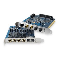
E-MU 1212M PCI
Срок обслуживания истек
Выбранное изделие относится к категории изделий с истекшим сроком обслуживания.
Для таких изделий техническая поддержка ограничивается предоставлением в интерактивном режиме материалов, размещенных на веб-узле технической поддержки пользователей Creative: решений из базы знаний, драйверов, обновленных версий приложений и документации по изделию.
База знаний: Самые популярные решения
Руководство пользователя по началу работы / инструкции по технике безопасности и нормативная информация
|
Ниже приведен список руководств пользователя по началу работы с E-MU 1212M PCI. |
Все материалы для загрузки
В следующем списке представлены совместимые с E-MU 1212M PCI материалы для загрузки.
Просмотр: Драйвер | Приложение | Все
Все материалы для загрузки
Для получения полного списка загрузочных файлов, Вы можете вручную найти их в нашей базе данных.
Драйвер
Дата выпуска:
5 Jul 11
Размер файла:
33.41 MB
Загрузка
Дата выпуска:
18 Nov 05
Размер файла:
21.45 MB
Загрузка
Приложение
Дата выпуска:
14 Jul 11
Размер файла:
29.28 MB
Загрузка
Дата выпуска:
5 Oct 05
Размер файла:
16.63 MB
Загрузка
-
Contents
-
Table of Contents
-
Bookmarks
Quick Links
O w n e r ‘ s M a n u a l
O w n e r ‘ s M a n u a l
Related Manuals for E-Mu 1212m
Summary of Contents for E-Mu 1212m
-
Page 1
O w n e r ’ s M a n u a l O w n e r ’ s M a n u a l… -
Page 2
Ballycoolin Business Park Scotts Valley, CA 95066 Blanchardstown Dublin 15 IRELAND Asia Pacific, Africa, Middle East E-MU Japan Creative Media K K Creative Technology Ltd Kanda Eight Bldg., 3F 31 International Business Park 4-6-7 Soto-Kanda Creative Resource. Singapore 609921 Chiyoda-ku, Tokyo 101-0021… -
Page 3: Table Of Contents
Safety First! ………………..14 Connector Types ………………..14 Installing the E-MU 1010 PCI Card ……………. 15 1212M Owners — Install the 0202 Daughter Card ……….16 Optional Sync Daughter Card Installation………….. 16 Connecting the MicroDock ………………. 17 WARNING: E-MU 0202 & MicroDock ………….. 17 Software Installation …………………
-
Page 4
Sidechain Diagram ………………47 Pre or Post Fader Aux Sends …………….48 Level, Pan, Solo & Mute Controls …………… 49 Main Section………………….50 TV Screen & Selectors ………………51 Effect ………………….51 Input ………………….52 Output ………………….52 Creative Professional… -
Page 5
Auxiliary Effects & Returns …………….. 53 Sidechain Diagram ………………53 Sync/Sample Rate Indicators …………….53 Output Section ………………..54 Main Inserts ………………..54 Main Output Fader ………………54 Output Level Meters ………………54 Monitor Output Level ………………54 Monitor Balance Control …………….54 Monitor Output Mute ……………… -
Page 6
Sync Daughter Card Supplement ……………. 114 SMPTE Conversion ………………114 SMPTE Options ………………..114 SMPTE Modes of Operation …………….115 Host Mode ………………..115 External Mode ………………… 115 Flywheel Mode ……………….. 115 Flywheel Modes ………………115 Stripe Mode ………………..116 Creative Professional… -
Page 7
Example SMPTE Connection …………….116 MIDI Time Code (MTC) ………………117 Word Clock In/Out ………………… 117 Getting in Sync ………………..119 Useful Information ………………..120 Cables — balanced or unbalanced? …………..120 Balanced Cables ………………120 Unbalanced Cables ………………120 Adapter Cables ……………….. -
Page 8
Creative Professional… -
Page 9: 1- Introduction
1- Introduction Welcome! Thank you for purchasing the E-MU 1616 PCI, E-MU 1616M PCI, or 1212M PCI Digital Audio System. Your computer is about to be transformed into a powerful audio processing workstation. We’ve designed this E-MU digital audio system to be logical, intuitive and above all, to provide you with pristine sound quality.
-
Page 10
(2) Turntable Preamp Inputs (with RIAA equalized preamplifier) (1) Stereo Headphone Output (with volume control) (3) Stereo Computer Speaker Outputs (with 1/8” jacks to connect powered speakers) 1212M PCI System Components E-MU 1212M • E-MU 1010 PCI Card • E-MU 0202 I/O Daughter Card •… -
Page 11: All Systems Include
Sync Daughter Card The Sync Daughter Card can be purchased as an optional upgrade for the 1616M, 1616 MicroDock and 1212M systems. The Sync Card adds Word Clock in and out for sample-synchronizing outboard digital equipment and SMPTE longitudinal time code in/out for syncing other recording equipment.
-
Page 12: Patchmix Dsp
Tips describe applications for the topic under discussion. Warnings are especially important, since they help you avoid activities that can cause damage to your files, your computer or yourself. Creative Professional…
-
Page 13: Installation
2 — Installation Setting Up the Digital Audio System 2 — Installation Setting Up the Digital Audio System There are six basic steps to installing your E-MU system: Remove any other sound cards you have in your computer. (Once you are sure that the E-MU card works properly, your old sound card can be reinstalled if desired.) Install the E-MU 1010 PCI card in your computer.
-
Page 14: Safety First
TOSLINK Optical Connector ADAT digital audio devices (or S/PDIF) ADAT Optical Out TOSLINK Optical Connector ADAT digital audio devices (or S/PDIF) Warning: Please verify that all cables are connected only to the proper compo- nents before powering up your system. Creative Professional…
-
Page 15: Installing The E-Mu 1010 Pci Card
Follow the computer manufacturer’s recommended procedure for opening the case. Remove the metal bracket from one PCI slot. If you have the E-MU 1212M system Note: Some or the Sync Daughter Card you’ll need to remove the bracket from two PCI slots.
-
Page 16: 1212M Owners — Install The 0202 Daughter Card
2 — Installation 1212M Owners — Install the 0202 Daughter Card 1212M Owners — Install the 0202 Daughter Card Unwrap the 0202 Daughter Card and get Figure 3 ready to install it. Connect the provided ribbon cable between the E-MU 1010 card and the 0202 Daughter card as shown in figure 3.
-
Page 17: Connecting The Microdock
2 — Installation Connecting the MicroDock Secure the card into the slot using one of the screws you placed aside earlier. After all components have been installed and securely fastened, close the computer case. Plug the power cord back into the wall outlet and turn on your computer. Connecting the MicroDock Connect the supplied EDI cable between the 1010 PCI Card and the MicroDock.
-
Page 18: Software Installation
When you install the 1616 PCI drivers, you will see a dialog box informing you either that the driver has not been certified by Windows Hardware Quality Labs (WHQL), or that the driver is signed by Creative Labs, Inc, and you will be asked if you would like to continue with the installation.
-
Page 19: Pci Card & Interfaces
3 — PCI Card & Interfaces The E-MU 1010 PCI Card 3 — PCI Card & Interfaces The E-MU 1010 PCI Card The E-MU 1010 PCI card is the heart of the system and contains E-MU’s powerful E-DSP chip. The powerful hardware DSP on this card leaves more power free on your CPU for additional software plug-ins and other tasks.
-
Page 20: The 0202 Daughter Card
DIN connectors on the card. The adapter cables convert the mini-DIN to standard DIN connectors used on most keyboards and synthesizers. Connect MIDI Out to the MIDI In port of your synthesizer and MIDI Out of your synth to MIDI In of the 0202 Daughter Card. Creative Professional…
-
Page 21: The Microdock
3 — PCI Card & Interfaces The MicroDock The MicroDock The MicroDock connects to the E-MU 1010 PCI card via the EDI cable. The MicroDock provides (4) balanced analog inputs, (2) microphone preamp inputs, The MicroDock is (6) balanced line-level analog outputs, (3) stereo 1/8” outputs for connecting powered completely “hot computer speakers, (2) MIDI inputs, (2) MIDI outputs, a stereo headphone output, pluggable”—…
-
Page 22: Front Panel Connections
The S/PDIF out can be configured in either Professional or Consumer mode in the Session Settings menu. The MicroDock can also send and receive AES/EBU digital audio through the use of a cable adapter. See “Cables — balanced or unbalanced?” details. Creative Professional…
-
Page 23: Adat Optical Digital Input & Output
3 — PCI Card & Interfaces The MicroDock ADAT Optical Digital Input & Output The ADAT optical connectors transmit and receive 8 channels of 24-bit audio using the Important: When ADAT type 1 & 2 formats. The word clock contained in the input data stream can be using any type of digital used as a word clock source.
-
Page 24: Digital Connections
Audio Outs MIDI Sound Module SAMPLE TRIGGERS TRANSPOSE MASTER/GLOBAL SAMPLE MANAGEMENT DIGITAL PROCESSING INC/YES PRESET DEC/NO MULTIMODE PRESET MANAGEMENT PRESET DEFINITION DYNAMIC PROCESING MIDI 2 ENTER VOLUME ESCAPE DRIVE SELECT LOAD SAVE AUDITION TRIGGER MODE MIDI MIDI In Creative Professional…
-
Page 25: Rear Panel Connections
3 — PCI Card & Interfaces The MicroDock Rear Panel Connections Turntable MIDI Port 48 Volt DC 4 Balanced Line Level Inputs Turntable Inputs (configured as 2 stereo pairs) (tied to line input 2) Ground Connector Power Input Pho no MIDI Cable 48 VDC 6 Balanced Line Level Outputs…
-
Page 26: Computer Speaker Analog Outputs
MIDI Cable 48 VDC AC Adapter 1010 PCI Card Connect Audio Desktop Powered Speakers to Monitors Desktop 1/8″ jacks Speakers Mixer & Speakers * Note: Line Inputs 2L/2R and Phono 2L/2R cannot be used at the same time. Creative Professional…
-
Page 27
3 — PCI Card & Interfaces The MicroDock 5.1 Surround Speaker Connections Center Left Phono Right MIDI Cable 48 VDC Front Front Left Right Rear Rear Front Rear Ctr/Sub Sub-Woofer (with built-in power amps) The 1/8” stereo jacks make it easy to connect to powered surround sound speakers. Only three stereo cables are necessary with many speaker systems (see above). -
Page 28
3 — PCI Card & Interfaces The MicroDock Creative Professional… -
Page 29: The Patchmix Dsp Mixer
4 — The PatchMix DSP Mixer PatchMix DSP 4 — The PatchMix DSP Mixer PatchMix DSP The PatchMix DSP Mixer is a virtual console which performs all of the functions of a typical hardware mixer and a multi-point patch bay. With PatchMix, you may not even need a hardware mixer.
-
Page 30: Mixer Window
Post Fader (both Aux Sends come after the channel fader) or Pre Fader (both Aux Sends come before the channel fader). The Pre-fader option allows you to use either Aux Send as another mix bus, which is unaffected by the channel fader. More Information. Creative Professional…
-
Page 31: E-Mu Icon In The Windows Taskbar
4 — The PatchMix DSP Mixer E-MU Icon in the Windows Taskbar E-MU Icon in the Windows Taskbar Right-clicking on the E-MU icon in the Windows taskbar calls the following window. Right-Click Here Opens the PatchMix DSP Mixer. Calls the PatchMix DSP help system. Disables the splash screen that appears at boot-up.
-
Page 32: The Session
Toolbar. The following dialog box appears. Select a Template or new Session at the desired sample rate Session Description Add your own comment or note about the Session Check this if you want to edit the New Session. Creative Professional…
-
Page 33: Open Session
96k, or 176k/192k. You can create your own templates by simply copying or saving sessions into the “Session Templates” folder (Program Files\Creative Professional\E-MU PatchMix DSP\Session Templates). There is also a Comment area that you can use to give yourself some clue as to what you were thinking when you created the session.
-
Page 34: Using External Clock
Use +4 Output setting input by inserting a meter into the first effect location in the strip. Adjust your external equipment outputs for the optimum signal level. See “To Set the Input Levels of a Strip” for details. Creative Professional…
-
Page 35
4 — The PatchMix DSP Mixer The Session Input Level Output Level Settings Settings Optical Optical Input Output Select Select S/PDIF Mic Soft Output Limiting Format On/Off • Inputs +4 or -10 Selects between Consumer level (-10dBV) or Professional level (+4dBu) inputs. (Use the -10dBV setting if your input is too weak.) •… -
Page 36: Input Mixer Strips
Strip solo or mute selected channels. Scribble Strips This screen shows a mono strip on the left and Click inside the scribble strip and type a a stereo strip on the right. name of up to eight characters. Creative Professional…
-
Page 37: Mixer Strip Creation
4 — The PatchMix DSP Mixer Mixer Strip Creation Mixer Strip Creation PatchMix DSP is a dynamically configurable mixer. Each mixer session can contain an Tip: Adding or deleting arbitrary number of strips up to a limit set by the number of available input sources a strip “defragments”…
-
Page 38: Multichannel Wave Files
3L = C 3R = Sub 3 (Tip = C Ring = Sub) E-DSP WAVE 5/6 Rear Left / Rear Right 2L = RL 2R = RR 2 (Tip = RL Ring = RR) E-DSP WAVE 7/8 Side Left / Side Right Creative Professional…
-
Page 39: Insert Section
4 — The PatchMix DSP Mixer Mixer Strip Creation Insert Section The Insert Section is next in line. PatchMix DSP effects can be selected from the Effects Palette and dropped into the insert locations. See “The Effects Palette”. Any number of effects can be inserted in series.
-
Page 40: The Insert Menu
Right-Click over the Insert section. A pop-up dialog box appears. Select “Insert Send/Return (Physical Output and Input)” from the list of options. The following dialog box appears. Creative Professional…
-
Page 41: Asio Direct Monitor Send/Return
4 — The PatchMix DSP Mixer Mixer Strip Creation If the source or Input destination you want to use is not available in the To Physical Output Insert list, they are probably Send/Return From Physical Input already being used elsewhere. Check the Panning input Strips, Inserts and Fader…
-
Page 42: Meter Inserts
You want the input signal level to drive the 24-bit ADCs into their optimum range without clipping. A reading of 0dB on an input meter indicates signal clipping. Level —12dB Each bar of the meter equals 1dB. The yellow bars begin at -12dB below full scale. Creative Professional…
-
Page 43: To Set The Input Levels Of A Strip
4 — The PatchMix DSP Mixer Mixer Strip Creation The insert meters are also useful to monitor incoming digital signals such as ADAT, ASIO or S/PDIF to make sure the mixer is receiving a proper signal level. They’re also great for troubleshooting, since you can place them virtually anywhere in the mixer. To Insert a Meter Right-Click on an Insert location of the mixer strip.
-
Page 44: Trim Pot Insert
A/D converters in order to get maximum resolution and signal-to-noise ratio from the converters. The phase invert switch inverts the polarity of the signal. It is generally used to correct for balanced lines and mics that are wired backwards. Creative Professional…
-
Page 45: Test Tone/Signal Generator Insert
4 — The PatchMix DSP Mixer Mixer Strip Creation To Add a Trim Pot Insert Right-Click over any of the Insert sections. A pop-up dialog box appears. Select Insert Trim Control from the list of options. A Trim Pot insert appears in the insert location.
-
Page 46: Managing Your Inserts
Click on the Effect (in the Insert section) and select Effect in the TV display. Click the Solo button. Method #2 Right-Click over the Effect you want to Solo (in the Insert section). A pop-up dialog box appears. Select Solo Insert from the list of options. Creative Professional…
-
Page 47: Aux Section
4 — The PatchMix DSP Mixer Mixer Strip Creation Aux Section The Auxiliary Sends tap the signal from the channel strips and sum them together before sending the mix to the Auxiliary Effects section. In a traditional mixing console, aux sends are used to send part of the signal to outboard effect devices, then return the effected signal back into the mix using the effect returns.
-
Page 48: Pre Or Post Fader Aux Sends
Input Post-Fader Aux Send Volume Fader & Mute affects both Aux Send Levels Fader Mute Send Return Amount Amount Side Chain Aux Bus 1 Send Return Amount Amount Side Chain Aux Bus 2 Main / Monitor Bus Output Creative Professional…
-
Page 49: Level, Pan, Solo & Mute Controls
4 — The PatchMix DSP Mixer Mixer Strip Creation Level, Pan, Solo & Mute Controls The Pan control comes before the Level Control and Aux Sends in the signal flow. On stereo strips Pan Controls we use an unconventional pan section with two pan pots –…
-
Page 50: Main Section
There is a stereo peak meter that indicates the signal strength for the main mix. The Monitor section has a volume, balance, and a mute control to cut off the monitor output. Creative Professional…
-
Page 51: Tv Screen & Selectors
4 — The PatchMix DSP Mixer Main Section TV Screen & Selectors The “TV screen” at the top of the main section is a multi-function display and control center for the input and output routings and effect controls. The three buttons at the top of the display select the current function of the display—Effect, Inputs or Outputs.
-
Page 52: Input
(or break) a connection. The Host Output screen displays and allows you to view the Host (ASIO or WAVE) outputs of the mixer. See “Insert Section” for information on how to connect the inserts. Creative Professional…
-
Page 53: Auxiliary Effects & Returns
4 — The PatchMix DSP Mixer Main Section Auxiliary Effects & Returns The section immediately below the TV Screen is where you assign the Auxiliary Effects. The Wet/Dry mix In a traditional mixing console, auxiliary effects sends are used to send part of the setting in the effect should signal to outboard effect devices, then return the effected signal back into the mix using normally be set to 100%…
-
Page 54: Output Section
This button completely cuts off the monitor output and provides a convenient way to instantly kill all sound without having to re-adjust the monitor level later. When the telephone rings, just hit the monitor mute to cut the noise. Creative Professional…
-
Page 55: Effects
5 — Effects Overview 5 — Effects Overview PatchMix DSP comes complete with a host of great core DSP effects including Compressors, Delays, Choruses, Flangers and Reverb. Each 32-bit effect has various parameters for editing, as well as factory presets. You can also create and save as many of your own effect presets as you wish.
-
Page 56: Fx Insert Chains
Select a category folder where your preset will be placed, and enter a new preset name for your FX Chain. Select a folder where your new preset will be placed, then type in a new preset name and click OK. Your preset is now saved. Creative Professional…
-
Page 57: The Order Of Effects
5 — Effects The Effects Palette The Order of Effects PatchMix DSP allows you to record your tracks without effects (dry) and monitor with effects enabled (wet). It works like this: If the effect is inserted BEFORE the ASIO send in the signal path, it will get recorded;…
-
Page 58: Importing And Exporting Core Fx Presets And Fx Insert Chains
To Import FX Category Folders This option imports complete category folders of FX Chains into the E-MU PatchMix DSP folder (normally located here: “C:\Program Files\Creative Professional\E-MU PatchMix DSP\Effect Presets”). If the name of an imported FX preset exactly matches a preset you already have, a number will be appended to end of the imported preset name.
-
Page 59: Fx Edit Screen
5 — Effects FX Edit Screen FX Edit Screen Click on an FX Insert to display the parameters for that effect. If an insert effect is not Note: Effects have selected, the FX display will read “No Insert”. to be placed into an insert location before you can Most effects have a wet/dry mix parameter to control the ratio of effect-to-plain signal.
-
Page 60: User Preset Section
Select the desired insert effect, highlighting it. The effect parameters appear in the TV screen. Click on the Edit button. A pop-up menu appears. Select New. A pop-up dialog box appears asking you to name the new preset. Name the preset and click OK. Your new preset is now saved. Creative Professional…
-
Page 61: Core Effects And Effects Presets
Core Effects and Effects Presets The Core Effects cannot be removed or copied. Effect presets (stored in “C:\Program Hint: You can open Files\Creative Professional\E-MU 1616\E-MU PatchMix DSP\Effect Presets”) can be the effects presets with copied, e-mailed or shared like any other computer file.
-
Page 62: List Of Core Effects
3-Band EQ 1-Band EQ Stereo Delay 1500 1-Band EQ Compressor Mono Delay 250 Compressor Mono Delay 1500 Compressor Chorus Mono Delay 250 Chorus Mono Delay 1500 Auto-Wah Flanger 4-Band EQ 3-Band EQ Total Effects Total Effects Total Effects Creative Professional…
-
Page 63: Core Effects Descriptions
5 — Effects Core Effects Descriptions Core Effects Descriptions 1-Band Para EQ This single band parametric equalizer is useful +15dB when you just want to boost or cut a single range of frequencies. For example, if you just Boost want to brighten up the lead vocal a bit, you Width might choose this EQ.
-
Page 64: 3-Band Eq
Sets the amount of cut (-) or boost (+) of the low frequency shelf. Range: -24dB to +24dB Low Corner Freq. Sets the frequency where the signal begins getting cut or boosted with the Low Gain control. Range: 50Hz to 800Hz Creative Professional…
-
Page 65: 4-Band Eq
5 — Effects Core Effects Descriptions 4-Band EQ This 4-band equalizer provides two shelving filters at the high and low ends of the frequency range and two fully parametric bands in the center. Up to ±24 dB of boost or cut is provided for each band.
-
Page 66: Auto-Wah
Range: 10ms to 1000ms Sweep Range Controls the amount of “wah” sweep. Range: 0% to 100% Center Frequency Sets the initial bandpass filter frequency. Range: 80Hz to 2400Hz Bandwidth Sets the width of the bandpass filter. Range: 1Hz to 800Hz Creative Professional…
-
Page 67: Chorus
5 — Effects Core Effects Descriptions Chorus An audio delay in the range of 15-20 milliseconds is too short to be an echo, but is perceived by the ear as a distinctly separate sound. If we now vary the delay time in this range, an effect called chorus is created, which gives the illusion of multiple sound sources.
-
Page 68: Basic Controls
Sets the ratio of input signal level to output signal level, or “how much” compression will be applied. Range: 1:1 to ×:1 Post Gain Amplifies the signal after it has been compressed to bring up the volume. Range -60dB to +60dB Creative Professional…
-
Page 69: Distortion
5 — Effects Core Effects Descriptions Parameter Description Attack Time Controls how quickly the gain is turned down after the signal exceeds the threshold. Range .1ms to 500ms Release Time Controls how fast the gain is returned to its normal setting after the signal has fallen below the threshold.
-
Page 70: Flanger
Range 05 to 100% LFO Waveform Selectable between Sine or Triangle wave. LFO L/R Phase Controls the stereo width by adjusting the phase difference between the left and right sweeps. Range: -180° to +180° Creative Professional…
-
Page 71: Freq Shifter
5 — Effects Core Effects Descriptions Freq Shifter This unusual effect is sometimes called “spectrum shifting” or “single sideband modulation”. Frequency shifting shifts every frequency in the signal by a fixed number of Hz which causes the harmonics to lose their normal relationship. The more common pitch shifter, in contrast, preserves the harmonic relationships of the signal and so is better suited to creating “musical”…
-
Page 72: Leveling Amp
Post Gain Amplifies the signal after it has been compressed to bring up the volume. Range 0dB to 36dB Creative Professional…
-
Page 73: Lite Reverb
5 — Effects Core Effects Descriptions Lite Reverb Reverberation is a simulation of a natural space such as a room or hall. The Lite Reverb algorithm is designed to simulate various rooms and reverberation plates while using fewer DSP resources than the Stereo Reverb. Up to five Lite Reverbs can be used at once.
-
Page 74: Mono Delays — 100, 250, 500, 750, 1500, 3000
Range: 1 millisecond to 3 seconds Feedback Sets the amount of delayed signal that will be recirculated through the delay line. Range: 0% to 100% High Freq. Rolloff Damps high frequencies in the feedback path. Range: 0% to 100% Creative Professional…
-
Page 75: Phase Shifter
5 — Effects Core Effects Descriptions Phase Shifter A phase shifter produces a fixed number of peaks and notches in the audio spectrum which can be swept up and down in frequency with a low frequency oscillator (LFO). This creates a swirly, ethereal sound with harmonically rich sound sources of a type of pitch shift with simpler sounds.
-
Page 76: Speaker Simulator
2 x 12 Combo Modeled from an American, 1960’ s era, 2-speaker combo amplifier. 4 x 12 Combo Modeled from an American, 1960’ s era, 4-speaker amplifier set. Metal Stack 1 & 2 Modeled from a modern era, power amplifier stack. Creative Professional…
-
Page 77: Stereo Delays — 100, 250, 500, 750, 1500
5 — Effects Core Effects Descriptions Stereo Delays — 100, 250, 500, 750, 1500 The Stereo Delays are true stereo delay lines in that the left and right channels are kept entirely separate from each other. The delay number refers to the maximum delay time that can be produced by the delay lines.
-
Page 78
Range: 0% to 100% High Freq. Damping Sets the rate at which high frequencies die away. Range: -10.0 to +3.0 damping factor Low Freq. Damping Sets the rate at which low frequencies die away. Range: -10.0 to +3.0 damping factor Creative Professional… -
Page 79: Vocal Morpher
5 — Effects Core Effects Descriptions Vocal Morpher This unique effect allows you to select two vocal phonemes and morph between them using an LFO. Phonemes are the consonants and vowels we use in articulating speech sounds and these sounds are very distinctive and evocative. 30 different phonemes are available and these can be shifted up or down in pitch for even more effects.
-
Page 80: Gate
Gate Delay Lookahead Envelope Follower/ Threshold Detector Release Threshold Max Gain Reduction The Gate behaves exactly as a straight wire, except when activated by a signal level below the Threshold (with Lookahead Off). Creative Professional…
-
Page 81: Parameters
5 — Effects Core Effects Descriptions Parameters Threshold When the input signal rises above the level set by the Threshold parameter, the Gate is triggered to turn on and go from its maximum gain reduction level up to 0dB gain. The turn-on threshold is adjustable anywhere between -70dB and 0dB (below the PatchMix nominal operating point of -12dBFS.) One of the keys to the smooth operation of the Gate is that the input Threshold level…
-
Page 82: Level Meter
The most-leftward gain shutoff value achieved by the Gain meter is set by the Max Gain Reduction parameter (values from -70dB to -infinity are off the meter.) The speed with which the Gain signal decays from 0dB to the shutoff value can be observed to change according to the Release time parameter. Creative Professional…
-
Page 83: Reshaper
5 — Effects Core Effects Descriptions Reshaper The Reshaper effect is a special purpose dynamics modification program, designed to “resculpt” the amplitude envelope of an audio signal. The effect uses an envelope follower and threshold detector to drive an ADSR-type gain stage, which can impose new attack, decay, sustain and release profiles on the signal’s original envelope.
-
Page 84
This parameter allows additional time to be added onto the Sustain phase after the input signal falls below the Release Threshold before transitioning to the Release phase. This extension of the Sustain phase is useful for altering the tail dynamics of the sound. Creative Professional… -
Page 85
5 — Effects Core Effects Descriptions Parameter Description Attack This parameter is adjustable in milliseconds to allow the Reshaper to Lookahead/ either “look ahead” and advance (negative values) or “delay” Delay (positive values) the response of the envelope detector relative to the dynamics of the input signal. -
Page 86: Multimode Eq
• Pseudo-stereo Effect — apply slightly different EQ to left and right channels to broaden the spread of a mono signal • Cross-over — left and right channels split a mono signal between highpass and lowpass with a sharp transition region. Creative Professional…
-
Page 87: Parameters
5 — Effects Core Effects Descriptions Parameters While the Multimode EQ has many parameters applicable to the various possible configurations of channels and filters, it selectively enables or hides parameters depending on their applicability to the current configuration. As a result, not all of the parameters listed below appear on-screen at the same time.
-
Page 88: Highpass -> Lowpass
In Highpass || Lowpass mode, the effect does not place any limitations on the Freq parameters of one filter relative to the other. In normal use, the Highpass Freq parameter will be higher than the Lowpass Freq parameter, creating a bandcut-type response: Creative Professional…
-
Page 89: Band Pass
5 — Effects Core Effects Descriptions However, when the Highpass Freq parameter is lower than the Lowpass Freq parameter, the combined filter response is basically flat, since the passbands of each filter combine to admit the entire spectrum. An exception occurs when there is resonance added to the filters — you’ll hear the resonant peaks as increased gain above the otherwise flat spectral response.
-
Page 90: Rfx Compressor
The RFX Compressor does not have the input gain control that is found on some compressors. These are typically used to align the input signal range to the compression threshold. Instead, we’ve allowed the RFX Compressor’s Threshold Creative Professional…
-
Page 91: Parameters
5 — Effects Core Effects Descriptions parameter to operate over an exceptionally large range of 0-60dB so that it can be “steered” to the appropriate range of the input signal. The output Gain parameter also operates — either manually or automatically — over the unusually large range of -60dB to +60dB in order to renormalize the compressor’s output for the next stage of the signal path.
-
Page 92: Gain
1:Ratio at the upper Threshold. Both the Soft Knee depth and the Ratio will affect the particular shape of the knee: shallower depths and higher Ratios will create a sharper knee, while greater depths and lower ratios create a softer knee. Creative Professional…
-
Page 93
5 — Effects Core Effects Descriptions Soft Knee (Varying the Soft Knee Threshold) Threshold: -20dB Ratio = 4:1 -20dB Knee Threshold -10dB Threshold -20dB Threshold -30dB -80dB This diagram shows the effect of varying the Soft Knee Threshold. Compres- sion is 1:1 (no compression) at the Knee Threshold and smoothly transforms into the selected compression ratio at the Compression Threshold. -
Page 94: Gate
At positive values, the signal path delay is zero; instead, a delay of up to 50 milli- seconds is inserted into the sidechain path containing the level detector. This delay can be used intentionally to cause the compressor to miss signal peaks, retaining the Creative Professional…
-
Page 95: Auto-Release
5 — Effects Core Effects Descriptions “punch” and “bite” of signal attacks while subsequently compressing the sustained portions of the sound. In general, both positive and negative values of this parameter are useful for applica- tions where the normal envelope of a signal is being creatively manipulated to achieve special effects.
-
Page 96: Max Compression
-3:1 -2:1 results in an output signal that -1.5:1 actually gets quieter as the input signal rises above the threshold. -1:1 This action can be useful for applications like ducking and for other special effects. -80dB Creative Professional…
-
Page 97: Input Mode
5 — Effects Core Effects Descriptions The diagram above shows the gain curves using a Threshold at -30dB and a range of negative compression ratios. At just past 1:INFINITE, the setting of 1:-100 causes input signals approaching 0dB to be only slightly decreased below -30dB. In contrast, the compression ratio of 1:-1 causes a 2dB gain reduction for each 1dB of additional input signal level, resulting in an output signal level that is folded down over the Threshold.
-
Page 98: Example Settings
• Threshold: -37dB (adjust according to the sound) • Ratio: 2:1 or 3:1 • Attack: Instantaneous • Release: 30 msec • Gain: 0dB • Soft Knee: Off • Gate: Off • Comp. Lookahead: -5 msec • Max. Compression: Unlimited Creative Professional…
-
Page 99
5 — Effects Core Effects Descriptions Vocal Compression/Spoken Word: This setup compresses the entire dynamic range of the vocal. Whenever there is a signal present, there is some compression taking place. • Threshold: Adjust so that the first bar of the meter comes on even on soft passages. -
Page 100: Multimode Eq Settings
• Threshold: -32dB (adjust to control amount of de-essing) • Ratio: 2.5:1 • Attack: Instantaneous • Release: 40 msec • Gain: 0dB • Soft Knee: Off • Gate: Off • Comp. Lookahead: -20 msec • Auto-release: Off • Max. Compression: Unlimited Creative Professional…
-
Page 101: E-Mu Powerfx
5 — Effects E-MU PowerFX E-MU PowerFX The hardware-accelerated effects of the E-MU Digital Audio System can also be used as E-MU PowerFX are VST inserts in Cubase. E-MU PowerFX allow you to use PatchMix DSP effects from not available at 88.2kHz, within Cubase with minimal load on your CPU.
-
Page 102
If you are using Cubase VST 5.1, you will have to insert an E-Delay Compensator into any other audio tracks to keep them time-aligned. Simply insert an E-Delay Compensator plug-in into the same insert location you used for E-MU PowerFX on any other audio tracks. That’s it. Creative Professional… -
Page 103: Automating E-Mu Powerfx
5 — Effects E-MU PowerFX Automating E-MU PowerFX E-MU PowerFX can be automated in Cubase LE (or other recording host) just like any Steinberg Cubasis other VST effect. When “Write Automation” is activated in Cubase, control changes does not have the control made in the PowerFX window during playback will be recorded on a special automation feature.
-
Page 104
1024) Sony Acid 4 Sony Vegas 5 Sony SoundForge 7 Power FX crashes when launched. Adobe Audition 1.5 Audio distortion & immediate lockup. FruityLoops Studio 4.5 Ableton Live 3.5 Distortion when FX parameters are changed. Cakewalk Sonar 3 Creative Professional… -
Page 105: Rendering Audio With E-Mu Powerfx
5 — Effects Rendering Audio with E-MU PowerFX Rendering Audio with E-MU PowerFX Rendering (sometimes called Export) is a mixdown process performed by the host application, which creates a new digital audio file from a multitrack song. Rendering allows a virtually unlimited number of VST effects to be used because the audio processing is performed out of realtime.
-
Page 106: E-Mu Vst E-Wire
Strip configured for E-Wire E-Wire bridges the gap between hardware I/O and the VST world. The E-Wire VST plug-in sends audio to a strip containing the desired effect. An ASIO Send routes the audio back to E-Wire VST. Creative Professional…
-
Page 107: E-Delay Compensator
5 — Effects E-MU VST E-Wire To Setup and use E-Wire: Setup PatchMix DSP Open PatchMix DSP application. Insert an ASIO Input mixer strip into PatchMix DSP. (Alternately, you can select “New Session”, select “E-Wire Example” and skip to step 6.) Mute the strip or turn the Fader all the way down.
-
Page 108: E-Delay Compensator Use
An E-Delay Compensator should be used when unprocessed audio tracks are played alongside tracks using a PowerFX or E-Wire plug-in. Simply insert an E-Delay Compensator into each track that doesn’t use a PowerFX or E-Wire send. Creative Professional…
-
Page 109: E-Delay Units Parameter
5 — Effects E-MU VST E-Wire E-Delay Units Parameter The Units value in the E-Delay dialog box should be set for the number of times you send ASIO down to the PatchMix DSP mixer and back in a single track. A single PowerFX insert chain with any number of effects only requires one delay unit because there was only one trip to the hardware and back.
-
Page 110
5 — Effects E-MU VST E-Wire Creative Professional… -
Page 111: Appendix
6 — Appendix Using High Sample Rates 6 — Appendix Using High Sample Rates Overview When operating at 176.4k or 192k sample rates, the mixer functionality and number of I/O channels are slightly reduced. The number of ADAT channels also decreases at the 88k/96k and 176/192k sample rates (due to the bandwidth limitations of the optical components).
-
Page 112
— — — — — — — — Line 1 Line 2 Line 3 (output) — — — — — — — — — — — — — — — — — — — — — — — — S/PDIF Total Creative Professional… -
Page 113: Wdm Recording And Playback Behavior
6 — Appendix Using High Sample Rates WDM Recording and Playback Behavior WDM recording and playback is supported at all PatchMix sample rates. The behavior of the driver with respect to PatchMix sample rate is described below. When PatchMix and the WDM audio content (.WAV file format, playback and record settings in WaveLab.
-
Page 114: Sync Daughter Card Supplement
PatchMix DSP mixer becomes visible. Pressing the SMPTE button brings up the SMPTE window. SMPTE Flywheel Mode Start Striping Current Time Start Time • Off • Continuous Flywheel • Fixed •1-time Jam Amount SMPTE Frame Stop Output Word Clock Output SMPTE Status/ Source Termination Rate Settings Striping Level Error Indicators Creative Professional…
-
Page 115: Smpte Modes Of Operation
6 — Appendix Sync Daughter Card Supplement Sets the transmitted frame rate when striping SMPTE. Mode (fps) Edit this field to set the start time in hours:minutes:seconds:frames for SMPTE Striping striping SMPTE. Initiates SMPTE Time Code generation at the SMPTE output beginning at Stripe Button the time set in the striping display.
-
Page 116: Stripe Mode
The Sync Card should not be used as both the SMPTE and word clock master. Word Clock is generated by the Digital Audio System and NOT by the software application (such as Cubase). SMPTE is not locked to Word Clock inside the Sync Card—they are completely independent. Creative Professional…
-
Page 117: Midi Time Code (Mtc)
6 — Appendix MIDI Time Code (MTC) MIDI Time Code (MTC) MIDI time code is basically SMPTE time code adapted to the world of MIDI. MTC MTC and SMPTE do specifies “absolute” location information in hours:minutes:seconds:frames, just like NOT synchronize at the SMPTE.
-
Page 118
E-MU 1010 CARD SYNC CARD Word Clock Termination ON This diagram shows the proper way to connect word clock if you don’t have a multi-output word clock generator. The last device in a Word Clock chain should have Termination ON. Creative Professional… -
Page 119: Getting In Sync
6 — Appendix Getting in Sync Getting in Sync Whenever you connect external digital audio devices together, you need to be aware of how they are synchronized to each other. Simply connecting digital out to digital in doesn’t guarantee that two digital devices are synced, even if audio is being passed. Unless you have set one to be the Master and the other a Slave, they are probably NOT synchronized and the quality of your audio will suffer.
-
Page 120: Useful Information
Unbalanced cables are more prone to hum and interference than balanced cables, but the shorter the cable, the less hum and noise is introduced into the system. Creative Professional…
-
Page 121: Adapter Cables
6 — Appendix Useful Information Adapter Cables 1/8” Mini-phone to 1/4” Adapters To connect headphones with an 1/8” (mini-phone) plug to the headphone jack on the MicroDock, you need a 1/8” to 1/4” adapter. These handy devices are available at electronic department stores everywhere.
-
Page 122: Grounding
To Improve the Appearance Settings: Open the Windows Control Panel. (Start, Settings, Control Panel). Select System. Select the Advanced Settings tab. Under Visual Effects, select Adjust for Best Performance. Click OK. Creative Professional…
-
Page 123: Technical Specifications
6 — Appendix Technical Specifications Technical Specifications Specifications: 1616 PCI System GENERAL 44.1 kHz. 48 kHz, 96 kHz, 192 kHz from internal crystal Sample Rates or externally supplied clock (no sample rate conversion) 24-bit I/O, 32-bit processing Bit Depth PCI 2.2 compliiant Form Factor: Universal Keyed, Short PCI Card PCI Specification 3.3V I/O, 5V Tolerant…
-
Page 124
(A-weighted, 1kHz, min. gain: 118 dB Dynamic Range: (A-weighted, min. gain): 118 dB SNR: (1kHz at-1dBFS): -105 dB (.0006%) THD+N: MICROPHONE PREAMP 1.5 Kohm Input Impedance: +6 dbV (8.2dBu) Max Level: (20Hz-20kHz, 150 ohm, unweighted): -129.5 dBu EIN: Creative Professional… -
Page 125
6 — Appendix Technical Specifications Specifications: 1616 PCI System (A-weighted, min. gain): 119 dB Signal-To-Noise Ratio: (1kHz at -1dBFS, min gain): -110dB (.0003%) THD+N: (20Hz — 20kHz, gain +40dB): ±0.08 dB Frequency Response: +48V Phantom Power: 5dB max compression (software selectable) Soft Limiter: HEADPHONE AMP Linear power amplifier… -
Page 126
ADAT (44.1kHz — 192kHz) External Sample Rate Sync: Optical S/PDIF (44.1kHz — 96kHz) Coaxial S/PDIF (44.1kHz — 192kHz) 24, 25, 30 drop-frame, 30 non-drop SMPTE to MTC, MTC to SMPTE Conversion SMPTE/LTC/MTC: (via optional Sync Daughtercard) SMPTE Striping Flywheel/Jam/Regenerate Creative Professional… -
Page 127
6 — Appendix Technical Specifications Specifications: 1616 PCI System GENERAL 44.1 kHz. 48 kHz, 88.2kHz, 96 kHz, 176.4kHz & 192 kHz from internal crystal or externally supplied clock Sample Rates: (no sample rate conversion) 16 or 24-bit I/O, 32-bit processing Bit Depths: PCI 2.2 compliiant Form Factor: Universal Keyed, Short PCI Card… -
Page 128
(1kHz at-1dBFS): -102 dB (.0008%) THD+N: MICROPHONE PREAMP 1.5 Kohm Input Impedance: +6 dbV (8.2dBu) Max Level: (20Hz-20kHz, 150 ohm, unweighted): -127 dBu EIN: (A-weighted, min. gain): 112.5 dB Signal-To-Noise Ratio: (1kHz at -1dBFS, min gain): -103 dB (.0007%) THD+N: Creative Professional… -
Page 129
6 — Appendix Technical Specifications Specifications: 1616 PCI System +48V Phantom Power: 5dB max compression (software selectable) Soft Limiter: HEADPHONE AMP Linear power amplifier CS4392 D/A Converter: 85 dB Gain Range: 50 mW Maximum Output Power: 22 ohms Output Impedance: (20Hz — 20kHz): +0.0/-0.07 dB Frequency Response: (A-weighted): 112 dB… -
Page 130
(Measured via Audio Precision 2) 44.1 kHz Optical Input 795ps ANALOG LINE INPUTS Servo-balanced, DC-coupled, low-noise input circuitry Type AK5394A A/D Converter Professional: +4 dBu nominal, 20 dBu maximum (balanced) Level (software selectable) Consumer: -10 dBV nominal, 6 dBV maximum (unbal- anced) Creative Professional… -
Page 131
6 — Appendix Technical Specifications Specifications: 1212 System (20Hz — 20kHz): +/- 0.05 db Frequency Response (1kHz, A-weighted): 120 dB Dynamic Range (A-weighted): 120 dB Signal-to-Noise Ratio (1kHz at -1dBFS): -110 dB (.0003%) THD + N (1kHz at -1dBFS): -115 dB Channel Crosstalk 10K ohm Input Impedance… -
Page 132
ADAT (44.1kHz — 192kHz) Optical S/PDIF (44.1kHz — 96kHz) External Sample Rate Sync: Coaxial S/PDIF (44.1kHz — 192kHz) 24, 25, 30 drop-frame, 30 non-drop SMPTE to MTC, MTC to SMPTE Conversion SMPTE/LTC/MTC: (via optional Sync Daughtercard) SMPTE Striping Flywheel/Jam/Regenerate Creative Professional… -
Page 133
6 — Appendix Technical Specifications Dimensions & Weight MicroDock 2.27 lb / 1.03 kg MicroDock Weight: W: 7.25″ H: 1.625″ L: 7.75″ Dimensions: W: 184 mm H: 41 mm L: 196 mm 1010 PCI Card 0.30lb / 0.14kg Weight: L: 6.7″ / 170.2mm Dimensions: 0202 Daughter Card 0.25lb / 0.10kg… -
Page 134: Internet References
Forums Unofficial E-MU Forum ……http://www.productionforums.com/emu/ KVR Forum ……….http://www.kvr-vst.com/forum/ Driver Heaven Forum……http://www.driverheaven.net/search.php?s MIDI Addict Forum …….. http://forum.midiaddict.com/search.php Home Recording Forum ……http://homerecording.com/bbs/ search.php?s=d866b60193933eb726660e7b d90dfb27 Sound-On-Sound Forum ……. http://sound-on-sound.com/forum/ Studio-Central Cafe Forum….http://studio-central.com/phpbb/search.php Sound Card Benchmarking….http://audio.rightmark.org Creative Professional…
-
Page 135: Declaration Of Conformity
6 — Appendix Internet References Declaration of Conformity E-MU Systems Trade Name: EM8850 Model No.: EM8870 EM8871 E-MU Systems Responsible Party: 1500 Green Hills Road, Address: Scotts Valley, CA 95066 U.S.A. This device complies with Part 15 of the FCC rules. Operation is subject to the following two conditions: (1) This device may not cause harmful interference, and (2) this device must accept any interference received, including interference that may cause undesired operation.
-
Page 136: Compliance Information
This product has been tested and found compliant with the limits set out in the EMC Directive for using connection cables shorter than 3 meters (9.8 feet). Notice If static electricity or electromagnetism causes data transfer to discontinue midway (fail), restart the application or disconnect and connect the Firewire cable again. Creative Professional…
-
Page 137: Index
Category create new preset 57 delete effects 57 rename effects 57 A/D Converter CDs, playing 37 1212M 130 Chorus 67 1616 127 using freq. shifter 71 1616M 123 Clicks & Pops, in the audio 19, 23, 117 AC3 Passthrough 23…
-
Page 138
Index overview 55 palette 55 D/A Converter phase shifter 75 1212M 131 placing into an insert location 39 1616 128 preset 1616M 124 create new 60 Damping, high frequency 73, 78 delete 61 Decay Time, lite reverb 73 overwrite 61… -
Page 139
Index Hardware DSP 123, 130 Jitter Spec Headphone Amp Specs 125, 129 1616 system 130 Headphone Output 23 1616M system 123 Headphones, using with the 0202 20 Help System 31 High Frequency Damping, stereo reverb 78 Label, scribble strip 49 High Frequency Decay Factor, lite reverb 73 Latency, monitoring without 41 High Frequency Rolloff… -
Page 140
61 session 31, 32 select user 60 at 176k/192k 111 Punch Enhancement user effect preset 60 reshaper effect 83 Noise Gate 80 using gate effect 80 Notes, Tips & Warnings 12 Punch Reducer, using reshaper effect 83 Creative Professional… -
Page 141
Robot Voice Effects, creating 77 send/return insert 51 Rotary, effect 75 Specifications Rubber Feet, installing on Audio Dock 18 1212M System 130 Rumble Filter, using multimode filter 86 1616 System 127 1616M System 123 Start Time, SMPTE 115 S/MUX 111… -
Page 142
WDM Recording & Playback Behavior 113 Wet/Dry Mix, effects 59 White Noise Generator 45 Window Appearance Settings 122 Windows Media Player 37 Windows Media Player, multichannel 38 Windows Taskbar, E-MU icon 31 Word Clock In/Out 117 XLR Connector 22 Zero-Latency Monitoring 41 Creative Professional…
This manual is also suitable for:
16161616m16161616m
-
Contents
-
Table of Contents
-
Bookmarks
Quick Links
O w n e r ‘ s M a n u a l
O w n e r ‘ s M a n u a l
Related Manuals for E-Mu 1212M
Summary of Contents for E-Mu 1212M
-
Page 1
O w n e r ’ s M a n u a l O w n e r ’ s M a n u a l… -
Page 2
E-MU 1616/1616 Digital Audio System Owner’ s Manual © 2006 E-MU Systems All Rights Reserved Software Version: 1.82 Revision: B E-MU World Headquarters E-MU Systems 1500 Green Hills Road Scotts Valley, CA 95066 Asia Pacific, Africa, Middle East Creative Technology Ltd 31 International Business Park Creative Resource. -
Page 3: Table Of Contents
Safety First! … 12 Connector Types … 12 Installing the E-MU 1010 PCI Card … 13 1212M Owners — Install the 0202 Daughter Card … 14 Optional Sync Daughter Card Installation… 14 Connecting the MicroDock … 15 WARNING: E-MU 0202 & MicroDock … 15 Software Installation …
-
Page 4
Overview of the Mixer … 27 Mixer Window … 28 Mixer Block Diagram … 28 Pre Fader or Post Fader … 28 E-MU Icon in the Windows Taskbar … 29 The Toolbar … 29 The Session … 30 New Session … 30 Open Session … -
Page 5
Rendering Audio with E-MU PowerFX … 82 General Tips for Rendering using PowerFX … 82 Tips for using Freeze Mode on Cubase LE … 82 Using E-MU PowerFX with WaveLab and SoundForge … 82 E-MU VST E-Wire… 83 E-Delay Compensator … 84 E-Delay Compensator Use … -
Page 6
E-Delay Units Parameter … 85 Grouping Tracks … 86 6 — Appendix … 87 Using High Sample Rates … 87 Overview … 87 WDM Recording and Playback Behavior … 89 Sync Daughter Card Supplement … 90 SMPTE Conversion … 90 SMPTE Options … -
Page 7: 1- Introduction
1- Introduction Welcome! Thank you for purchasing the E-MU 1616 PCI, E-MU 1616M PCI, or 1212M PCI Digital Audio System. Your computer is about to be transformed into a powerful audio processing workstation. We’ve designed this E-MU digital audio system to be logical, intuitive and above all, to provide you with pristine sound quality.
-
Page 8
1- Introduction Welcome! 1616M PCI System Components • E-MU 1010 PCI Card • MicroDockM • EDI (E-MU Digital Interface Cable) • +48VDC AC Adapter • MIDI Breakout Cable • Digital Audio System Software/Driver Installation CD-ROM • Production Tools Software Bundle CD-ROM •… -
Page 9: All Systems Include
All Systems Include: The E-MU 1010 PCI Card is the heart of all three systems. Its powerful hardware DSP processor allows you to use over 16 simultaneous hardware-based effects, which place minimal load on your computer’s CPU. The E-MU 1010 PCI Card also provides eight- channels of ADAT®…
-
Page 10: Patchmix Dsp
DVDs, or general computer use. You’ll want to keep up with the latest software and options for your E-MU digital audio system. You can find all of this, plus other helpful information, at the E-MU Website: http://www.emu.com.
-
Page 11: Installation
There are six basic steps to installing your E-MU system: Remove any other sound cards you have in your computer. (Once you are sure that the E-MU card works properly, your old sound card can be reinstalled if desired.) Install the E-MU 1010 PCI card in your computer.
-
Page 12: Safety First
2 — Installation Setting Up the Digital Audio System Please read the following sections as they apply to your system as you install the E-MU 1010, paying special attention to the various warnings they include. Prior to installing the hardware, take a few moments to write down the 18-digit serial number, which is located on the back of the box and on the 1010 PCI Card.
-
Page 13: Installing The E-Mu 1010 Pci Card
Follow the computer manufacturer’s recommended procedure for opening the case. Remove the metal bracket from one PCI slot. If you have the E-MU 1212M system or the Sync Daughter Card you’ll need to remove the bracket from two PCI slots.
-
Page 14: 1212M Owners — Install The 0202 Daughter Card
After all components have been installed and securely fastened, close the computer case. Connect the supplied network-type cable from the 10 BaseT jack on the E-MU 1010 PCI card labeled “EDI” to the matching connector labeled “EDI” on the MicroDock. The cable supplied with the MicroDock is specially shielded to prevent unwanted RF emissions.
-
Page 15: Connecting The Microdock
E-MU 1010 PCI card, or the MicroDock. WARNING: E-MU 0202 & MicroDock If you have both the E-MU 0202 I/O card and the MicroDock, DO NOT connect both to the E-MU 1010 PCI card. They cannot be used together.
-
Page 16: Software Installation
Software Installation Installing the E-MU 1010 Drivers The first time you restart your PC after installing the E-MU 1010 PCI card, you will need to install the PatchMix DSP software and E-MU 1010 PCI card drivers. Windows XP , Windows XP x64, Windows 2000 The software is not compatible with other versions of Windows.
-
Page 17: Pci Card & Interfaces
3 — PCI Card & Interfaces The E-MU 1010 PCI Card The E-MU 1010 PCI card is the heart of the system and contains E-MU’s powerful E-DSP chip. The powerful hardware DSP on this card leaves more power free on your CPU for additional software plug-ins and other tasks.
-
Page 18: The 0202 Daughter Card
192kHz The 0202 Daughter Card The 0202 Daughter card is the companion card for E-MU 1010 systems which don’t include the MicroDock. The 0202 Daughter card provides one pair of 24-bit balanced analog inputs and one pair of 24-bit balanced analog outputs, plus MIDI in and out.
-
Page 19: The Microdock
The MicroDock The MicroDock connects to the E-MU 1010 PCI card via the EDI cable. The MicroDock provides (4) balanced analog inputs, (2) microphone preamp inputs, (6) balanced line-level analog outputs, (3) stereo 1/8” outputs for connecting powered computer speakers, (2) MIDI inputs, (2) MIDI outputs, a stereo headphone output, and a RIAA equalized turntable preamp section which is “normalled”…
-
Page 20: Front Panel Connections
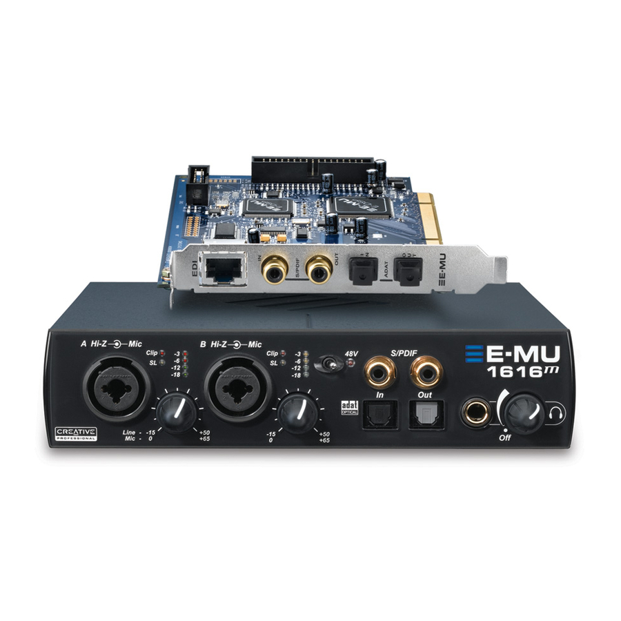
3 — PCI Card & Interfaces The MicroDock Front Panel Connections Preamp Section The front panel mono Mic/Line inputs A & B can be used as balanced microphone inputs, hi-Z guitar pickup inputs, or line level inputs. The Neutrik combination jack accepts microphones using a standard XLR connector or line level/hi-Z inputs (such as an electric guitar) using a standard 1/4 inch TRS/TS connector.
-
Page 21: Adat Optical Digital Input & Output
For this reason it has a very clean signal that can be used as another stereo output if you need it. E-MU PCI Digital Audio Systems Settings”. Optical connections have certain (page 31) 3 — PCI Card &…
-
Page 22: Digital Connections
3 — PCI Card & Interfaces The MicroDock Front Panel Analog Connections Use the 3-pin XLR jack for Low Impedance microphones. Line Clip Line — Mic — Use the center Phone Jack for Instrument High Impedance instruments such as electric guitar or bass.
-
Page 23: Rear Panel Connections
+4 dBu standard in the I/O screen of the Session Settings dialog box. Settings”. The maximum input and output line levels are matched when the input and output settings are set to the same mode (pro or consumer) in the I/O preferences screen. E-MU PCI Digital Audio Systems Turntable MIDI Port Ground…
-
Page 24: Computer Speaker Analog Outputs
MIDI Out to the MIDI In port of your synthesizer and MIDI Out of your synth to MIDI In of the MicroDock MIDI cable. EDI Connector (Card) Connects the MicroDock to the E-MU 1010 PCI card using a CAT5-type computer cable. The cable supplied with the MicroDock is specially shielded to prevent unwanted RF emissions.
-
Page 25
Surround Channels E-DSP WAVE 1/2 Front Left/Front Right 1L = FL 1R = FR E-DSP WAVE 3/4 Center/Subwoofer E-DSP WAVE 5/6 Rear Left/Rear Right E-DSP WAVE 7/8 Side Left/Side Right E-MU PCI Digital Audio Systems Center Phono Front Rear Ctr/Sub 1/4”… -
Page 26
3 — PCI Card & Interfaces The MicroDock Creative Professional… -
Page 27: The Patchmix Dsp Mixer
“Sessions” at will. To Invoke the PatchMix DSP Mixer Left-click once on the E-MU icon DSP mixer window appears. Overview of the Mixer Physical Input Strips…
-
Page 28: Mixer Window
4 — The PatchMix DSP Mixer Overview of the Mixer Mixer Window The Mixer consists of four main sections. Application Toolbar Lets you manage sessions and show/hide the various views. Main Section Controls all the main levels, aux buses, and their inserts. This section also has a “TV” which shows parameters for the currently selected effect and the input/output patching.
-
Page 29: E-Mu Icon In The Windows Taskbar
E-MU Icon in the Windows Taskbar Right-clicking on the E-MU icon in the Windows taskbar calls the following window. Right-Click Here The Toolbar Save Session Session Open Session New Session Calls up the “New Session” dialog box. Open Session Calls up the standard “Open” dialog box, allowing you to open a saved Session.
-
Page 30: The Session
4 — The PatchMix DSP Mixer The Session The Session The current state of the PatchMix DSP mixer (fader settings, effects routings…every- thing!) can be saved as a Session. Whenever you create or modify a mixer setup, all you have to do is Save it to be able to recall it at a later time. Before you begin using PatchMix DSP, you need to set it up to be compatible with the other software applications you may be running.
-
Page 31: Open Session
96k, or 176k/192k. You can create your own templates by simply copying or saving sessions into the “Session Templates” folder (Program Files\Creative Professional\E-MU PatchMix DSP\Session Templates). There is also a Comment area that you can use to give yourself some clue as to what you were thinking when you created the session.
-
Page 32: Using External Clock
4 — The PatchMix DSP Mixer The Session • Internal/External Clock Selects between internal or external word clock source as the master clock source for the system • Sample Rate Selects the sample rate when using internal clock. Your choices are: 44.1kHz, 48kHz, 88.2kHz, 96kHz, 176.4kHz, 192kHz.
-
Page 33
• S/PDIF Output Format Selects between S/PDIF or AES/EBU format for S/PDIF . This sets the S/PDIF-AES status bit, but does not affect the signal level. E-MU PCI Digital Audio Systems 4 — The PatchMix DSP Mixer The Session Output Level… -
Page 34: Input Mixer Strips
4 — The PatchMix DSP Mixer Input Mixer Strips Input Mixer Strips PatchMix DSP Input Mixer Strips are stereo except for the MicroDock Mic/Line inputs. Each input mixer strip can be divided into four basic sections. • Insert Section Effects, EQ, External/Host Sends & Returns can be inserted into the signal path. •…
-
Page 35: Mixer Strip Creation
WAVE 3/4, WAVE 5/6, WAVE 7/8 — Additional WDM channels Select Pre-Fader Aux Sends or leave the box unchecked for Post-Fader Aux Sends. Click OK to create a new strip or Cancel to cancel the operation. E-MU PCI Digital Audio Systems See “Overview of the Mixer”. The New Mixer…
-
Page 36: Multichannel Wave Files
4 — The PatchMix DSP Mixer Mixer Strip Creation To Delete a Mixer Strip: Click the top of the mixer strip you wish to delete. A red border appears around the strip, indicating that it is selected. Click on the Delete Mixer Strip button, or right-click and choose Delete, or use the Delete key on the PC keyboard.
-
Page 37: Insert Section
Select the effect you want, drag it over the insert section, then drop it into an insert location. To rearrange the order of effects, simply drag and drop them into the desired order. E-MU PCI Digital Audio Systems See “The Effects Palette”. Any number of See “To Add a Send Inserts”.
-
Page 38: The Insert Menu
4 — The PatchMix DSP Mixer Mixer Strip Creation The Insert Menu Right-Clicking over the insert section brings up a pop-up selection box containing various insert options to help you control and manage your inserts. To Add a Send Insert: This type of insert send splits the signal at the insert point and sends it out to the selected destination.
-
Page 39: Asio Direct Monitor Send/Return
In this case, set the PatchMix DSP stereo pan controls hard left and right, mono pan controls to center, and the fader to 0dB. E-MU PCI Digital Audio Systems Input To Physical Output…
-
Page 40: Meter Inserts
4 — The PatchMix DSP Mixer Mixer Strip Creation To Add an ASIO Direct Monitor Send/Return: Right-Click over the Insert section. A pop-up dialog box appears. Select Insert ASIO Direct Monitor from the list of options. The following dialog box appears. Choose one of the Send Outputs.
-
Page 41: To Set The Input Levels Of A Strip
You can enlarge the meter view by clicking on the insert meter in a strip and selecting the “Effect” button at the top of the TV screen. The “I/O Settings” in the Digital Audio System allow you to set the input levels to -10dBV (consumer equipment level) or +4dBu (professional equipment level) for each analog input.
-
Page 42: Trim Pot Insert
MicroDock’s ultra-high-quality A-D converters. The Digital Audio System includes Insert “Trim Pot” controls, but since they adjust the signal level AFTER the signal has been digitized, this will not recover any lost resolution.
-
Page 43: Test Tone/Signal Generator Insert
Click on the Test Tone insert to view and adjust the controls in the TV screen. To move the Test Tone to another location, simply drag and drop it into the desired position. E-MU PCI Digital Audio Systems Signal Type (Sine wave, White or Pink Noise)
-
Page 44: Managing Your Inserts
4 — The PatchMix DSP Mixer Mixer Strip Creation Managing Your Inserts To Delete an Insert: Right-Click over the Insert you wish to delete. A yellow line around the insert location indicates that it is selected. A pop-up dialog box appears. Select Delete Insert to remove the selected insert or select Delete All Inserts to remove all inserts.
-
Page 45: Aux Section
ASIO pair. You could route one of the Aux buses to the Monitor out to create a monitor mix while sending the main mix off to your audio recording software. E-MU PCI Digital Audio Systems Sidechain Diagram (Post-Fader Aux Sends)
-
Page 46: Pre Or Post Fader Aux Sends
4 — The PatchMix DSP Mixer Mixer Strip Creation Pre or Post Fader Aux Sends When you create a New Mixer Strip you have the option to place both Aux Sends after the channel volume fader and mute control or you can place them before the fader and mute.
-
Page 47: Level, Pan, Solo & Mute Controls
Level Control Mute & Solo Buttons Scribble Strip E-MU PCI Digital Audio Systems The Pan control comes before the Level Control and Aux Sends in the signal flow. On stereo strips we use an unconventional pan section with two pan pots – one for the left part of the signal and one for the right part of the signal.
-
Page 48: Main Section
4 — The PatchMix DSP Mixer Main Section Main Section Physical/Host Select Buttons “TV” Screen Master Aux Send Amounts Main Insert Section Output Fader & Meters The main section contains all controls for controlling the main mix elements as well as a “TV screen”…
-
Page 49: Tv Screen & Selectors
Send is going and where the Return is coming from. The bypass or solo buttons at the top of the display are available for Send/Return type inserts only. E-MU PCI Digital Audio Systems for detailed information about the individual Effect Location Effect Bypass &…
-
Page 50: Input
4 — The PatchMix DSP Mixer Main Section Input Selecting the Input display view shows a graphic representation of the PatchMix DSP Mixer inputs. This screen is only a display, unlike the Effects and Outputs screens, which allow you to make routing changes. Input routing changes are made by adding mixer strips.
-
Page 51: Auxiliary Effects & Returns
48kHz clock until the proper external clock is restored. The “LOCKED” LED will be off and the two units are NOT synchronized. Always check the “LOCKED” LED when using an external clock source to make sure you are sample- locked. E-MU PCI Digital Audio Systems Input Input Sidechain Diagram…
-
Page 52: Output Section
4 — The PatchMix DSP Mixer Main Section Output Section Clip Indicators Main Output Level Fader Main Insert Section Output Level Meters Main Inserts The main inserts allow you to apply effects to the main stereo signal coming out of the mixer (both mains and monitor).
-
Page 53: Effects
Effects Chains and the folders that contain them. For more information on Effects Chains, see “FX Insert Chains” on page 54. New Folder button Import/Export FX Button E-MU PCI Digital Audio Systems Effect Categories Core Effects (Single Effect) Multi-Effects (Effect Combinations) Distortion Lo-fi Drums &…
-
Page 54: Fx Insert Chains
5 — Effects The Effects Palette To Select an Effect Click the FX button to bring up the Effects Palette. The effect palette contains numerous folders containing effects presets. Click on any folder to open it. Select the effect you wish to use by clicking on it with the left mouse button and while continuing to hold the mouse button, drag the effect into the desired location on the PatchMix DSP mixer screen and release the mouse button.
-
Page 55: The Order Of Effects
Select “Rename Category”. A pop-up dialog box appears, asking you to “Enter New Category Name.” Click OK to rename the folder or Cancel to cancel the operation. E-MU PCI Digital Audio Systems Input If you want Effects 1L/1R to be recorded, insert them Above the ASIO Send.
-
Page 56: Importing And Exporting Core Fx Presets And Fx Insert Chains
You can share presets with your friends or download new presets from the Internet. To Import Core FX Presets This option imports complete folders of Core FX presets into the E-MU PatchMix DSP folder (normally located here: “C:\Program Files\Creative Professional\E-MU PatchMix DSP\Core Effects”).
-
Page 57: Fx Edit Screen
Method #1 Click on the Insert Effect (in the Insert section). Click the Solo button in the TV display. E-MU PCI Digital Audio Systems Note: Effects have to be placed into an insert location before you can program them.
-
Page 58: User Preset Section
5 — Effects FX Edit Screen Method #2 Right-click over the Insert Effect you want to Solo (in the Insert section). A pop-up menu appears. Select “Solo Insert” from the list of options. The other Insert Effect names in the strip will “gray-out”…
-
Page 59: Core Effects And Effects Presets
Core Effects and Effects Presets The Core Effects cannot be removed or copied. Effect presets (stored in “C:\Program Files\Creative Professional\E-MU 1616\E-MU PatchMix DSP\Effect Presets”) can be copied, e-mailed or shared like any other computer file. E-MU PCI Digital Audio Systems…
-
Page 60: List Of Core Effects
5 — Effects List of Core Effects List of Core Effects Stereo Reverb Frequency Shifter Lite Reverb Auto-Wah Compressor Vocal Morpher Leveling Amp 1-Band Para EQ Chorus 1-Band Shelf EQ Flanger 3-Band EQ Distortion 4-Band EQ Speaker Sim Mono Delay 100 Rotary Mono Delay 250 Phase Shifter…
-
Page 61: Core Effects Descriptions
Corner Frequency Sets the frequency where the signal begins getting cut or boosted with the Gain control. Range: 80Hz to 16kHz E-MU PCI Digital Audio Systems This single band parametric equalizer is useful when you just want to boost or cut a single range of frequencies.
-
Page 62: 3-Band Eq
5 — Effects Core Effects Descriptions 3-Band EQ This versatile equalizer provides two shelving filters at the high and low ends of the frequency range and a fully parametric band in the center. Up to ±24 dB of boost or cut is provided for each band.
-
Page 63: 4-Band Eq
Sets the amount of cut (-) or boost (+) of the low frequency shelf. Range: -24dB to +24dB Low Corner Freq. Sets the frequency where the signal begins getting cut or boosted with the Low Gain control. Range: 50Hz to 800Hz E-MU PCI Digital Audio Systems page 62. Mid 2-Band High-Shelf Corner…
-
Page 64: Auto-Wah
5 — Effects Core Effects Descriptions Auto-Wah This effect creates the sound of a guitar wah-wah pedal. The “Wah” filter sweep is automatically triggered from the amplitude envelope of the input sound. Auto-wah works well with percussive sounds such as guitar or bass. The Auto-Wah is a bandpass filter whose frequency can be swept up or down by an envelope follower, which extracts the volume contour of the input signal.
-
Page 65: Chorus
This level is called the Threshold, which just happens to be the most important control on the compressor. Delay Level Control Threshold Ratio Attack Release E-MU PCI Digital Audio Systems Post Gain 5 — Effects Core Effects Descriptions…
-
Page 66: Basic Controls
5 — Effects Core Effects Descriptions Basic Controls The three main controls of a compressor are the Ratio control, the Threshold control and the Gain control. If the signal falls below the Threshold, no processing will take place. Signals exceeding the Threshold will have gain reduction applied as set by the ratio control.
-
Page 67: Distortion
Post EQ Center Freq. Sets the frequency of the output bandpass filter. Range: 80Hz to 24kHz Post EQ Bandwidth Sets the width of the output bandpass filter. Range: 80Hz to 24kHz E-MU PCI Digital Audio Systems Bandpass Filter Distortion EQ BW Gain…
-
Page 68: Flanger
5 — Effects Core Effects Descriptions Flanger A flanger is a very short delay line whose output is mixed back together with the original sound. Mixing the original and delayed signals results in multiple frequency cancellations known as a comb filter. Since the flanger is a type of filter, it works best with harmonically rich sounds.
-
Page 69: Freq Shifter
Range: .01Hz to 24kHz Left Direction Sets pitch shift up or down for the left channel. Right Direction Sets pitch shift up or down for the right channel. E-MU PCI Digital Audio Systems Frequency Shifted (100 Hz) 1200 1500…
-
Page 70: Leveling Amp
5 — Effects Core Effects Descriptions Leveling Amp The first compressors developed in the 1950’s were based on a slow-acting optical gain cells which were able to control the signal level in a very subtle and musical way. This effect is a digital recreation of the leveling amps of yesteryear. The leveling amp uses a large amount of “lookahead delay”…
-
Page 71: Lite Reverb
Sets the volume of the initial wall reflections. Range: 0% to 100% Reverberance Sets the amount of scattering of the early reflections and the reverberation cloud. Range: 0% to 100% E-MU PCI Digital Audio Systems Core Effects Descriptions Time 5 — Effects…
-
Page 72: Mono Delays — 100, 250, 500, 750, 1500, 3000
5 — Effects Core Effects Descriptions Mono Delays — 100, 250, 500, 750, 1500, 3000 A delay line makes a copy of the incoming audio, holds it in memory, then plays it back after a predetermined time. The delay number refers to the maximum delay time that can be produced by the delay line.
-
Page 73: Phase Shifter
The Rotary incorporates acceleration and deceleration as you switch between the two speeds. Parameter Description Speed Switches between slow or fast rotor speeds with acceleration and deceleration as the speed changes. E-MU PCI Digital Audio Systems 5 — Effects Core Effects Descriptions…
-
Page 74: Speaker Simulator
5 — Effects Core Effects Descriptions Speaker Simulator The Speaker Simulator provides realistic guitar speaker responses and is designed for use with guitar, bass or synthesizer. Twelve popular guitar amp speaker cabinets are modeled. There is only one parameter on this effect. Just select the speaker you want and listen. Normally this effect should be used with the Mix control set to 100%.
-
Page 75: Stereo Delays — 100, 250, 500, 750, 1500
Sets the amount of delayed signal that will be recirculated through the delay line. Range: 0% to 100% High Freq. Rolloff Damps high frequencies in the feedback path. Range: 0% to 100% E-MU PCI Digital Audio Systems Feedback R Delay Time…
-
Page 76
5 — Effects Core Effects Descriptions Stereo Reverb Reverberation is a simulation of a natural space such as a room or hall. The stereo reverb algorithm is designed to simulate various halls, rooms and reverberation plates. Decay time defines the time it takes for the reflected sound from the room to decay or die away. -
Page 77: Vocal Morpher
LFO Rate Controls how fast the phonemes morph back and forth. Range: .01Hz to 10Hz LFO Waveform Selects the waveform for the morph: Sinusoid, Triangle, Sawtooth E-MU PCI Digital Audio Systems Phoneme B Phoneme A 5 — Effects Core Effects Descriptions…
-
Page 78: E-Mu Powerfx
E-MU PowerFX E-MU PowerFX The hardware-accelerated effects of the E-MU Digital Audio System can also be used as VST inserts in Cubase. E-MU PowerFX allow you to use PatchMix DSP effects from within Cubase with minimal load on your CPU.
-
Page 79
Setup E-MU PowerFX Make sure the blue button on. The blue “Signal Present” indicators will be illuminated if E-MU PowerFX is properly patched into a signal path. Drag the desired effects from the Effects Palette to the center Insert strip. -
Page 80: Automating E-Mu Powerfx
• If DSP resources ARE available, but no Hardware I/O Paths are available, the plug-in will run in soft pass-through mode. • If the sample rate is changed in the middle of a E-MU PowerFX session, E-MU PowerFX plug-ins will be bypassed, since the hardware effects cannot operate at 88kHz, 96kHz, 176.4kHz or 192kHz.
-
Page 81
Steinberg WaveLab 5 Sony Acid 4 Sony Vegas 5 Sony SoundForge 7 Adobe Audition 1.5 FruityLoops Studio 4.5 Ableton Live 3.5 Cakewalk Sonar 3 E-MU PCI Digital Audio Systems Compatible? Note Instrument Freeze triggers error if not in render mode. -
Page 82: Rendering Audio With E-Mu Powerfx
MU PowerFX are used while rendering audio, the rendering process must proceed at realtime rate. Some host applications are not designed to handle realtime rendering and this can cause problems. E-MU PowerFX can be used with these applications if you are willing to follow certain guidelines.
-
Page 83: E-Mu Vst E-Wire
E-Wire bridges the gap between hardware I/O and the VST world. The E-Wire VST plug-in sends audio to a strip containing the desired effect. An ASIO Send routes the audio back to E-Wire VST. E-MU PCI Digital Audio Systems Send to Strip…
-
Page 84: E-Delay Compensator
E-Wire on any other audio tracks. That’s it. E-Delay Compensator As audio is transferred back and forth between the VST host application and the E-MU sound hardware, a delay in the audio stream is incurred. Normally this delay is compensated for automatically by the host application, but not all VST host applica- tions support this automatic compensation.
-
Page 85: E-Delay Compensator Use
If you use two Cubase inserts in series on a track both using PowerFX or E-Wire, you would set the number parameter E-MU PCI Digital Audio Systems Track 3 E-Delay E-Delay Compensator Use For host applications that don’t support…
-
Page 86: Grouping Tracks
E-Delay Compensator on the output of the group or bus. • E-MU Digital Audio System and PatchMix DSP must be installed. • E-Wire is compatible with Cubase SX/SL/LE, Cubase VST, Wavelab, and Cakewalk Sonar (via DirectX-VST adapter) among others.
-
Page 87: Appendix
I/O from the New Session window. Once you have selected one of the three session types, you will not be able to change to another type without starting a new session. E-MU PCI Digital Audio Systems Select the Type of Session you need Analog & S/PDIF Session Analog &…
-
Page 88
At the 192kHz sample rate, you may choose one of these three options: 1. Keep all Analog I/O, but lose S/PDIF 2. Keep all Analog I/O, but lose ADAT E-MU 1616 Hardware Inputs & Outputs at 176.4k or 192k Input Output Source Analog &… -
Page 89: Wdm Recording And Playback Behavior
PatchMix. If the sample rates are mismatched, NO AUDIO will be produced or recorded. In other words, the WDM driver does not perform sample rate conversion of any kind when PatchMix is running at 88.2kHz, 96kHz, 176.4kHz or 192kHz. E-MU PCI Digital Audio Systems…
-
Page 90: Sync Daughter Card Supplement
6 — Appendix Sync Daughter Card Supplement Sync Daughter Card Supplement SMPTE Conversion One of the main functions of the Sync Daughter Card is to convert SMPTE (LTC) to MIDI Time Code (MTC) and vice-versa. The term “Host MTC” refers to MTC, which is generated or used by the host application (Cubase, etc.).
-
Page 91: Smpte Modes Of Operation
Upon any dropout, MTC continues outputting Quarter-frame messages at 1-Time Jam Sync the same rate (flywheeling) without monitoring the SMPTE input until the Stop button is pressed. E-MU PCI Digital Audio Systems Sync Daughter Card Supplement “Word Clock In/Out”. 6 — Appendix…
-
Page 92: Stripe Mode
The Sync Card should not be used as both the SMPTE and word clock master. Word Clock is generated by the Digital Audio System and NOT by the software application (such as Cubase). SMPTE is not locked to Word Clock inside the Sync Card—they are completely independent.
-
Page 93: Midi Time Code (Mtc)
The E-MU 1010 PCI card can be externally clocked from the ADAT input, S/PDIF input or from the Sync Daughter card (if installed). In a digital studio, all digital devices in the system should run off the same master Word Clock.
-
Page 94
ADAT Optical ADAT Optical or AES Digital Word Clock Termination OFF E-MU 1010 CARD SYNC CARD Word Clock Termination ON This diagram shows the proper way to connect word clock if you don’t have a multi-output word clock generator. The last device in a Word Clock chain should have Termination ON. -
Page 95: Getting In Sync
In the first example, only the A/D converters on the external device are being used. Only one lightpipe is needed as long as PatchMix is set to receive its word clock signal from the external device. The external A/D is the Master and the E-MU DAS is the Slave. External Device supplies Master Clock (;7(51$/…
-
Page 96: Useful Information
Useful Information Cables — balanced or unbalanced? All inputs and outputs on the E-MU Digital Audio System are designed to use either balanced or unbalanced cables. Balanced signals provide an additional +6dB of gain on the inputs and are recommended for best audio performance, although unbalanced cables are fine for most applications.
-
Page 97: Adapter Cables
This simple adapter cable allows you to receive AES/EBU digital audio via the S/PDIF input on the E-MU 1010 PCI card. This cable may also work to connect S/PDIF out from the 1010 PCI card to the AES/EBU input of other digital equipment.
-
Page 98: Grounding
6 — Appendix Useful Information Grounding In order to obtain best results and lowest noise levels, make sure that your computer and any external audio devices are grounded to the same reference. This usually means that you should be using grounded AC cables on both systems and make sure that both systems are connected to the same grounded outlet.
-
Page 99: Technical Specifications
(A-weighted): 120 dB Signal-to-Noise Ratio (1kHz at -1dBFS): -110 dB (.0003%) THD + N (1kHz at -1dBFS): -120 dB Channel Crosstalk -79 dB at 60Hz Common-mode Rejection E-MU PCI Digital Audio Systems 795ps 15.4 Watts 6 — Appendix Technical Specifications…
-
Page 100
THD + N (1kHz at -1dBFS): < -115 dB Stereo Crosstalk 560 ohms Output Impedance MIC PREAMP/LINE INPUT (2) E-MU XTC combo mic preamp & Hi-Z line input w/ soft Type: limiter +60 dB Gain Range: (min. gain, 20Hz — 20kHz) +0.0/-0.1dB Frequency Response: (1kHz, min. -
Page 101
220 pF Input Capacitance: DIGITAL I/O • 2 in/2 out coaxial (transformer coupled) • 2 in/2 out optical (software switchable with ADAT) S/PDIF • AES/EBU or S/PDIF (switchable under software control) E-MU PCI Digital Audio Systems 6 — Appendix Technical Specifications… -
Page 102
6 — Appendix Technical Specifications Specifications: 1616 PCI System • 8 channels, 24-bit @ 44.1/48 kHz ADAT • 4 channels, 24-bit @ 96 kHz (S-MUX compatible) • 2 channels, 24-bit @ 192 kHz 2 MIDI in, 2 MIDI out MIDI SYNCHRONIZATION 44.1kHz, 48 kHz, 88.2kHz, 96 kHz, 176.4kHz, 192 kHz Internal Crystal Sync:… -
Page 103
Dynamic Range (A-weighted): 112 dB Signal-to-Noise Ratio (1kHz at -1dBFS): -102.5 dB (.0012%) THD + N (1kHz at -1dBFS): -115 dB, Channel Crosstalk 10K ohm Input Impedance E-MU PCI Digital Audio Systems 795ps 10 Watts 6 — Appendix Technical Specifications… -
Page 104
(1kHz at -1dBFS): -98 dB (.0012%) THD + N (1kHz at -1dBFS): < -115 dB Stereo Crosstalk MIC PREAMP/LINE INPUT (2) E-MU XTC combo mic preamp & Hi-Z line input w/ soft Type: limiter +60 dB Gain Range: (min. gain, 20Hz — 20kHz) +0.0/-0.1dB Frequency Response: (1kHz, min. -
Page 105
• 8 channels, 24-bit @ 44.1/48 kHz • 4 channels, 24-bit @ 96 kHz (S-MUX compatible) ADAT • 2 channels, 24-bit @ 192 kHz 2 MIDI in, 2 MIDI out MIDI SYNCHRONIZATION E-MU PCI Digital Audio Systems 6 — Appendix Technical Specifications… -
Page 106
ASIO2. WDM/MME/DirectSound. x64 Drivers Drivers WDM: 2-in/8-out at 44.1kHz, 48kHz, 88.2kHz, 96kHz WDM: 2-in/4-out at 176.4kHz & 192kHz Proprietary 64-channel audio link over CAT-5 cable EDI (E-MU Digital Interface) Anti-pop speaker protection minimizes noise during Anti-Pop Protection power-up SRSync SourceRMS jitter in picoseconds ULTRA-LOW JITTER CLOCK 44.1 kHz Internal Crystal 596ps… -
Page 107
• 8 channels, 24-bit @ 44.1/48 kHz • 4 channels, 24-bit @ 96 kHz (S-MUX compatible) ADAT • 2 channels, 24-bit @ 192 kHz 1 MIDI in, 1 MIDI out (16 channels) MIDI E-MU PCI Digital Audio Systems 6 — Appendix Technical Specifications… -
Page 108
6 — Appendix Technical Specifications Specifications: 1212 System SYNCHRONIZATION 44.1kHz, 48 kHz, 88.2kHz, 96 kHz, 176.4kHz, 192 kHz Internal Crystal Sync: ADAT (44.1kHz — 192kHz) Optical S/PDIF (44.1kHz — 96kHz) External Sample Rate Sync: Coaxial S/PDIF (44.1kHz — 192kHz) 24, 25, 30 drop-frame, 30 non-drop SMPTE to MTC, MTC to SMPTE Conversion SMPTE/LTC/MTC: (via optional Sync Daughtercard) -
Page 109
W: 184 mm H: 41 mm L: 196 mm 1010 PCI Card 0.30lb / 0.14kg Weight: L: 6.7″ / 170.2mm Dimensions: 0202 Daughter Card 0.25lb / 0.10kg Weight: L: 5.04″ / 128mm Dimensions: E-MU PCI Digital Audio Systems 6 — Appendix Technical Specifications… -
Page 110: Internet References
MIDI & Audio Recording … MIDI & Audio Recording … ASIO, Cubase & Digital Audio … Cubase Users Group… Forums Unofficial E-MU Forum … KVR Forum … Driver Heaven Forum… MIDI Addict Forum … Home Recording Forum … Sound-On-Sound Forum …
-
Page 111: Declaration Of Conformity
The supplied interface cables must be used with the equipment in order to comply with the limits for a digital device pursuant to Subpart B of Part 15 of FCC Rules. E-MU PCI Digital Audio Systems 6 — Appendix Internet References…
-
Page 112
6 — Appendix Internet References Compliance Information United States Compliance Information FCC Part 15 Subpart B Class B using: CISPR 22 (1997) Class B ANSI C63.4 (1992) method FCC Site No.90479 Canada Compliance Information ICES-0003 Class B using: CISPR 22 (1997) Class B ANSI C63.4 (1992) method Industry of Canada File No.IC 3171-B European Union Compliance Information… -
Page 113: Index
Aux Bus 45 Auxiliary Effects Assignment 51 Auxiliary Returns 51 Auxiliary Sends 45 used as extra mix busses 51 E-MU PCI Digital Audio Systems Background program, disabling 29 Balance Control, monitor 52 Balanced Cables 23, 96 Bit Depth 99 Block Diagram, mixer 28…
-
Page 114
E-MU 0202 Daughter Card description 18 E-MU 1010 PCI Card description 17 installing 13 E-MU Icon, in taskbar 29 Envelope, reverberation 71, 76 E-Wire 83 Exit PatchMix DSP Services 29 Exporting Core FX & FX Insert Chains 56 External Clock 32, 93, 95… -
Page 115
44 menu 38 meter 41 mixer strip 37 solo 44, 57 types 37 Installing E-MU 0202 daughter card 14 E-MU 1010 PCI card 13 sync daughter card 14 Interface ADAT 18, 21 EDI 24 MIDI 18, 24 required cable 15… -
Page 116
Index Mono Delays 72 MTC 93 enabling 93 to SMPTE Conversion 90 Mute mixer strip 47 monitor 48 mixer strip 35 preset category 55 session 29, 30 at 176k/192k 87 user effect preset 58 Notes, Tips & Warnings 10 OpAmps 99 Optical Cables 97 Optical S/PDIF 21, 33 Order of Effects 55… -
Page 117
Session 30 creating 176k/192k 31, 87 creating new 30 templates 31 at 176k/192k 31, 87 Setting Up the E-MU Digital Audio System 11 Settings I/O 32 input level 20 system 31 Sidechain Effects 51 routing 45 Signal Generator Insert 43…

E-MU PCIe Digital Audio Systems
1
Owner’s Manual
Owner’s Manual
(Ocr-Read Summary of Contents of some pages of the E-Mu 1212M Document (Main Content), UPD: 13 August 2023)
-
114, 6 — Using High Sample Rates Overview 114 Creative Professional or… or… Microphone & Line 3 Input enabled Line Input 1 & ADAT Input enabled Line Inputs 1 & 3 enabled 2 Chan. ADOCK 2 Chan. 2 Chan. ADOCK ADOCK 2 Chan. or… Microphone & ADAT Input enabled 2 Chan. ADOCK 2 Chan. At the 176.4kHz or 192kHz sample rates, you sacrifice S/PDIF, line input 3, and line output 3. ADAT optical is reduced t…
-
27, 4 — The PatchMix DSP Mixer PatchMix DSP E-MU 1820M/1820/1212M PCI Digital Audio System 27 4 — The PatchMix DSP Mixer PatchMix DSP The PatchMix DSP Mixer is a virtual console which performs all of the functions of a typical hardware mixer and a multi-point patch bay. With PatchMix, you may not even need a hardware mixer. PatchMix DSP performs many audio operations such as ASIO/ WAVE routing, volume control, stereo panning, equalization, effect processing, effect send/return routing, main m…
-
45, 4 — The PatchMix DSP Mixer Mixer Strip Creation E-MU Digital Audio System 45 Managing Your Inserts To Delete an Insert: f Tip: Select the Insert and press the Delete key to delete the plug-in from the strip. 1. Right-Click over the Insert you wish to delete. A yellow line around the insert location indicates that it is selected. A pop-up dialog box appears. 2. Select Delete Insert to remove the selected insert or select Dele…
-
137, E-Mu 1212M 7 — Appendix Internet References E-MU 1820M/1820/1212M PCI Digital Audio System 137 Compliance Information United States Compliance Information FCC Part 15 Subpart B Class B using: CISPR 22 (1997) Class B ANSI C63.4 (1992) method FCC Site No.90479 Canada Compliance Information ICES-0003 Class B using: CISPR 22 (1997) Class B ANSI C63.4 (1992) method Industry of Canada File No.IC 3171-B European Union Compliance Information EN55024 (1998) EN55022 (1998) Class B EN61000-3-2 (2001) EN610…
-
109, 5 — Effects E-MU E-Wire VST E-MU Digital Audio System 109 In practical use, however, you’ll probably never need to use more than one E-Wire VST on a single track since PowerFX effects can be placed in series. We have included this feature “just in case” you need it. Here’s one more example of how to use the E-Delay Compensator with different numbers of PowerFX/E-Wire sends on each track. The delay compensation on each track must equal the tr…
-
103, 5 — Effects E-MU PowerFX E-MU Digital Audio System 103 Automating E-MU PowerFX Steinberg Cubasis does not have the control automation feature. E-MU PowerFX can be automated in Cubase LE (or other recording host) just like any other VST effect. When “Write Automation” is activated in Cubase LE, control changes made in the PowerFX window during playback will be recorded on a special “Audio Mix” track located at the bottom of the Arrange Window. When “Automation Read” is…
-
66, 5 — Effects Core Effects Descriptions 66 Creative Professional Auto-Wah This effect creates the sound of a guitar wah-wah pedal. The “Wah” filter sweep is automatically triggered from the amplitude envelope of the input sound. Auto-wah works well with percussive sounds such as guitar or bass. The Auto-Wah is a bandpass filter whose frequency can be swept up or down by an envelope follower, which extracts the volum…
-
9, 1- Introduction Welcome! E-MU 1820M/1820/1212M PCI Digital Audio System 9 1- Introduction Welcome! Thank you for purchasing the E-MU 1820M, E-MU 1820 or E-MU 1212M digital audio system. Your computer is about to be transformed into a powerful audio processing workstation. We’ve designed this E-MU digital audio system to be logical, intuitive and above all, to provide you with pristine sound quality. All th…
-
7, Creative Professional 7 7 — Appendix ……………………………………………………….. 117 Sync Daughter Card Supplement…………………………………………………………………………117 SMPTE Conversion …………………………………………………………………………………………117 SMPTE Features ………………………………………………………………………………………….. 117 SMPTE Opti…
-
28, 4 — The PatchMix DSP Mixer Overview of the Mixer 28 Creative Professional Mixer Window The Mixer consists of four main sections. A simplified diagram of the mixer is shown below. Pre Fader or Post Fader When creating a new Mixer Strip, you have the option for the Aux Sends to be Post Fader (both Aux Sends come after the channel fader) or Pre Fader (both Aux Sends come before the channel fader). The Pre-fader option allows you to use either Aux Send as another mix bus, which is unaffe…
-
68, 5 — Effects Core Effects Descriptions 68 Creative Professional Basic Controls The three main controls of a compressor are the Ratio control, the Threshold control and the Gain control. If the signal falls below the Threshold, no processing will take place. Signals exceeding the Threshold will have gain reduction applied as set by the ratio control. This important control allows you to dial in the range of…
-
22, 3 — PCI Card & Interfaces The AudioDock 22 Creative Professional Front Panel Connections Preamp Section Warning: Some microphones cannot tolerate phantom power and may be damaged. Check the microphone’s specifications and requirements before using phantom power. The front panel mono Mic/Line inputs A & B can be used as balanced microphone inputs, hi-Z guitar pickup inputs, or line level inputs. The Neutrik combination jack accepts microphones using a standard XL…
-
123, E-Mu 1212M 7 — Appendix Word Clock In/Out E-MU 1820M/1820/1212M PCI Digital Audio System 123 Word Clock In: Receives word clock (sample clock) from another digital device such as a digital video deck, digital recorder or digital mixer. Word Clock Out: Sends word clock (sample clock) to another digital recorder. Word clock is always output, whether it is generated by the internal clock or passed through from the word clock input. 7…
-
46, 4 — The PatchMix DSP Mixer Mixer Strip Creation 46 Creative Professional Aux Section The Auxiliary Sends tap the signal from the channel strips and sum them together before sending the mix to the Auxiliary Effects section. In a traditional mixing console, aux sends are used to send part of the signal to outboard effect devices, then return the effected signal back into the mix using the effect returns. Th…
-
117, 7 — Appendix Sync Daughter Card Supplement E-MU 1820M/1820/1212M PCI Digital Audio System 117 7 — Appendix Sync Daughter Card Supplement SMPTE Conversion Warning: SMPTE and MTC do not provide sample sync for digital I/O. You must use Word Clock, S/PDIF or ADAT sync. One of the main functions of the Sync Daughter Card is to convert SMPTE (LTC) to MIDI Time Code (MTC) and vice-versa. The term “Host MTC” r…
-
119, E-Mu 1212M 7 — Appendix SMPTE Background E-MU 1820M/1820/1212M PCI Digital Audio System 119 Stripe Mode This mode is used to record SMPTE time code onto an audio track of another recorder. SMPTE is output when the Start button is pressed in the System Settings menu and begins at the time set by the Start Time setting. MTC is also simultaneously output from the Sync Daughter Card MIDI out. SMPTE and MTC will continue to be output until the Stop button is pressed. See Striping SMP…
-
4, 4 E-MU 1820M/1820/1212M PCI Digital Audio System The AudioDock Front Panel Indicators ……………………………………………………………… 23 The MIDI Input Indicators …………………………………………………………………………….. 23 The Clock Source and Sample Rate Indicators ………………………………………………… 23 The Clock Source LEDs ……………………………