
32
APPA 107N/109N
DIGITAL MULTIMETER
INSTRUCTION MANUAL

TABLE OF CONTENTS
1. SAFETY 1
2. PRODUCT DESCRIPTION 2
3. PANELS OVERVIEW 4
3.1 REAR PANEL 5
4. BUTTONS FUNCTION 6
4.1 LIGHT (Yellow Button) 6
4..2 BAR 6
4.3 PEAK HOLD 7
4.4 AUTO HOLD 7
4.5 BLUE 7
4.6 M/M/A 7
4.7 REL △ 7
4.8 RANGE 7
4.9 dB/dBm 8
4.10 STORE 8
4.11 RECALL 8
4.12 RED (Data Log) 8
4.12.1 LOG RATE 8
5.7 CAPACITANCE MEASUREMENTS 17
9. MAINTENANCE 28
10. ACCESSORIES 30
4.12.2 DATA LOG-IN 9
5.5 CONTINUITY CHECK 15
5.6 CURRENT MEASUREMENTS (AC, DC, AC + DC) 16
4.12.3 DATA LOG-OUT 9
4.12.4 ▲ 9
4.12.5 ▼ 9
5. OPERATION 11
5.1 VOLTAGE MEASUREMENTS 11
5.2 Milli VOLTAGE MEASUREMENTS (AC,DC,AC + DC) 12
5.3 OHM AND LOW VOLTAGE OHM MEASUREMENTS 13
5.4 DIODE TEST 14
5.8 FREQUENCY AND DUTY FACTOR MEASUREMENTS 18
5.9 TEMPERATURE MEASUREMENTS 19
6. SPECIAL FEATURE DESCRIPTIONS 20
7. POWER-UP OPTIONS 20
8. SPECIFICATIONS 21
4.13 DTGIT 10

1
1. SAFETY
Review the following safety precautions to avoid injury and prevent damage to this
product or any products connected to it. To avoid potential hazards, use the prod-
uct only as specified.
CAUTION. These statements identify conditions or practices that could
result in damage to the equipment or other property.
WARNING. These statements identify conditions or practices that could
result in personal injury or loss of life.
Symbols on the product
Refer to manual Double Insulated High Voltage
Specific precautions
Use proper Fuse. To avoid fire hazard, use only the fuse type and rating
specified for this product.
Do not operate without covers. To avoid personal injury , do not apply any
voltage or current to the product without the covers in place.
Electric overload. Never apply a voltage to a connector on the product that is
outside the range specified for that connector.
Avoid electric shock. To avoid injury or loss of life, do not connect or disconnect
probes or test leads while they are connected to a voltage source.
Do not operate in wet/damp conditions. To avoid electric shock , do not operate
this product in wet or damp conditions.
2
2. PRODUCT DESCRIPTION
The meters provide many functions and features, Depending on your meter
type, each type of meter has own features described in this manual.
The following list provides a comparison of the features between meters.
FUNCTION 107N
DC Voltage •
AC Voltage •
mV Voltage •
Resistance •
Lo Ohm •
Diode Test •
Continuity Check •
DC Current •
AC Current •
Capacitance •
Frequency •
Duty Factor •
•
Temperature (K-Type)
109N
•
•
•
•
•
•
•
•
•
•
•
•
•
3
FEATURES 107N 109N
Auto Power Off (30 minutes) • •
Analog Bargraph Display , 42 Segments Graph • •
Center Zero Analog Bargraph • •
Auto Calibration • •
Auto HOLD • •
Autorange With Rang HOLD • •
Auto Fuse Detector • •
Beep Guard • •
dBm / dB Readings (600Ω for dBm) • •
Delta mode • •
Hazard Warning • •
Storage and Recell up to 1000 Memories • •
Low Battery Indicator • •
MAX / MIN / AVG • •
Peak Hold (0.5ms) • •
Safety IEC, UL, CSA IEC, UL, CSA
CE Mark • •
True RMS (AC / DC + AC) • •
VAC / Hz Dual Display • •
Water / Dust Resistant • •
Battery 9V 9V
600V High Energy Fuse • •
LCD Backlight • •
Auto Backlight Off (15 Minutes) • •
RS — 232 Phototronic Serial Port • •
RS — 232 Cable Option •
Win DMM 100 software Option •
Holster and Stand • •
Data Log up to 40k memories 6K •
4
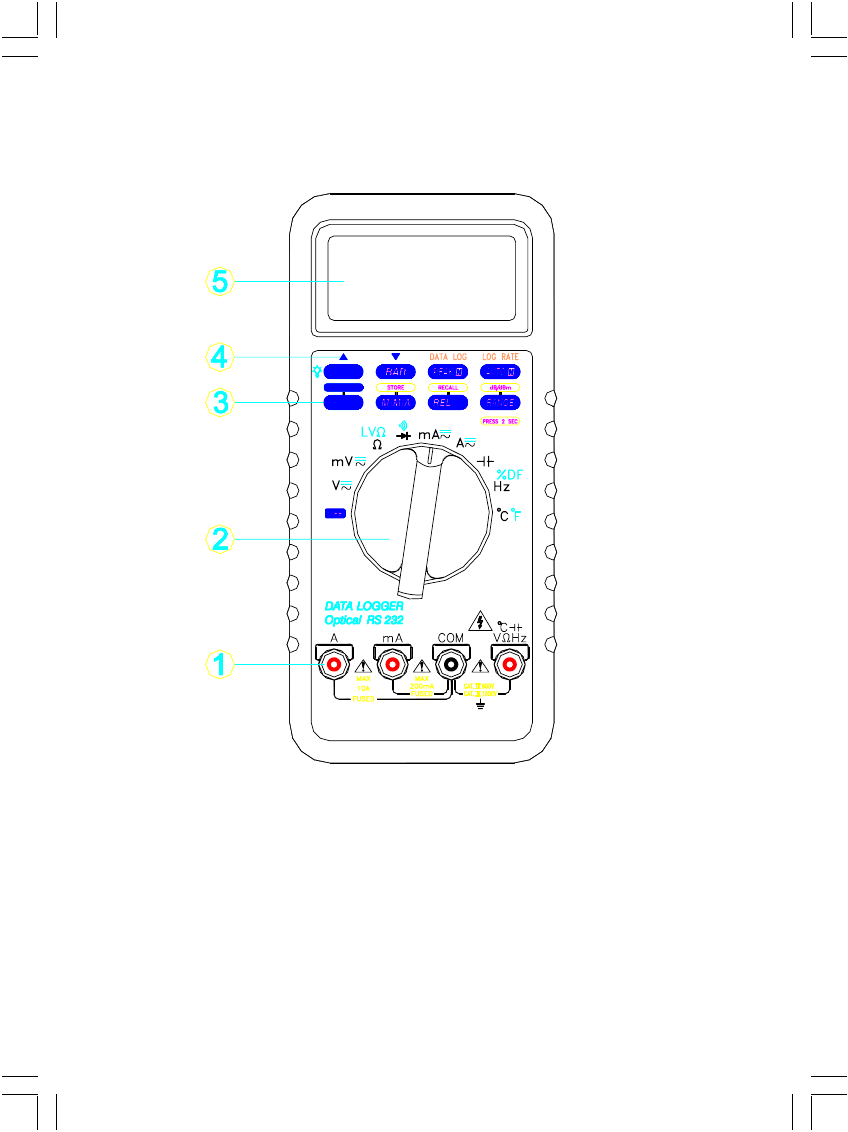
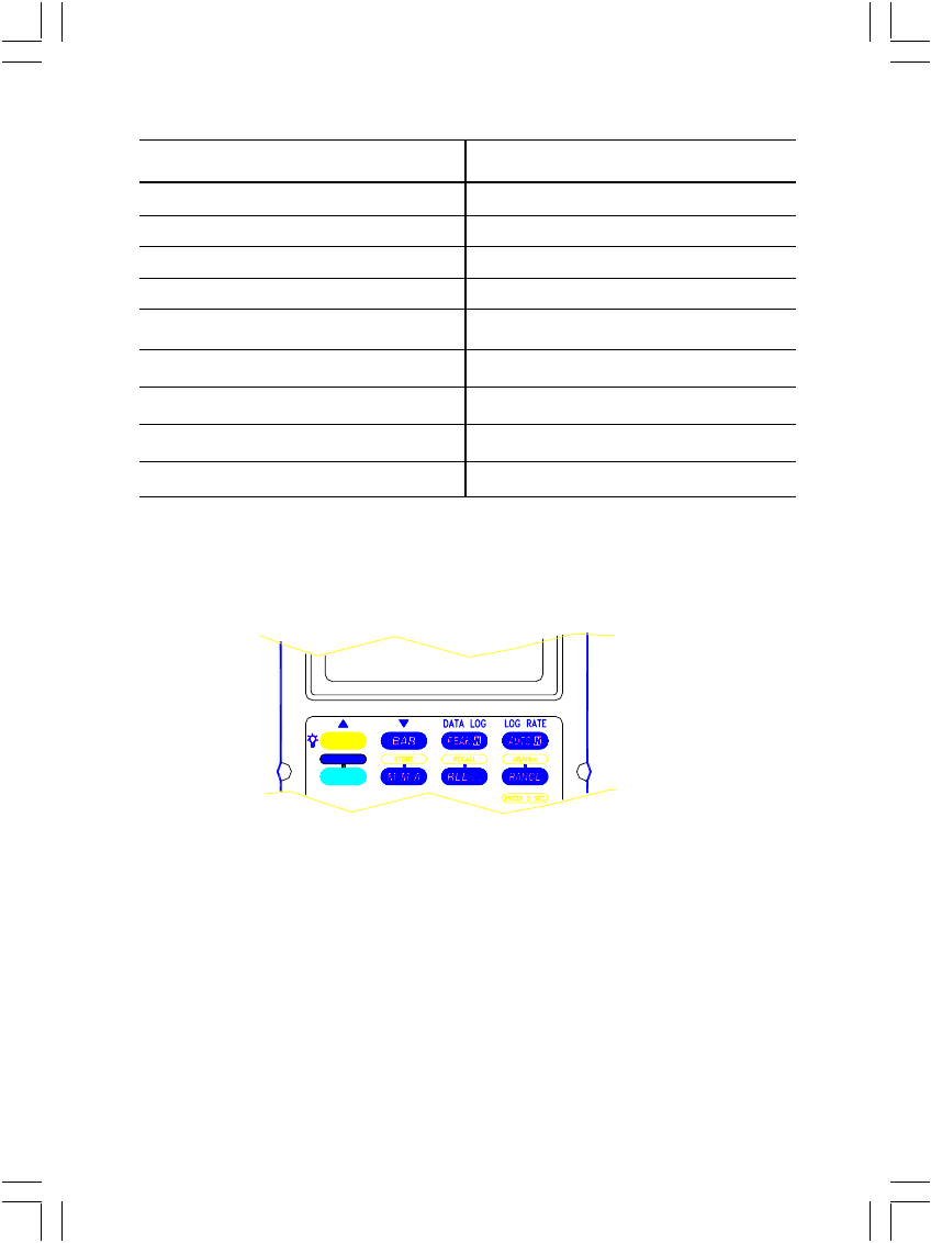
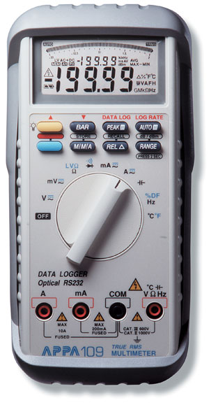
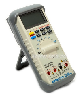
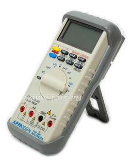
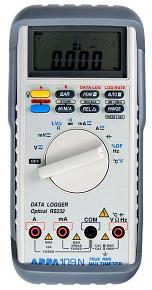
3. FRONT PANEL OVERVIEW
Figure 1
1. Input connectors.
2. Measurement function dial. Black labels are the initial settings, blue labels are
selected by the blue button.
3. Function buttons.
4. Data log features.
5. LCD display with dual numeric readout.
5
3-1 DISPLAY INDICATORS
Figure 2
1. Auto range indicator.
2. True RMS mode indicator.
3. AC, DC and AC + DC mode indicators.
4. Low voltage resistance indicator.
5. Auto hold indicator.
6. Peak hold indicator.
7. Maximum, Minimum and Average indicators.
8. Main display unit indicators.
9. Sub-display unit indicators.
10. STORE and RECALL indicator.
11. High voltage input warning (>60V DC, 30V ACrms).
12. is indicator (low battery)
13. Average indicator equals to (MAX + MIN)/2.
14. DATA LOG indicator.
6
Indicator Unit Indicator Unit
µ micro V Volt
m milli A Ampere
K kilo F Farad
M mega Hz Hertz
△ delta S Second
% percent Fahrenheit
dB Decibel (1V ref.) ℃ Celsius
dBm Decibel(1mW on 600Ω) Ω ohm
G gega n nano
4. BUTTONS FUNCTION
Prediction : Buzzer beeps once for every key-press.
Buzzer beeps twice for every invalid key-press.
Figure 3
4.1 LIGHT
* This button is used to turn on or turn off the backlight.
* This button is disabled in DATA LOG functions.
4.2 BAR
* This button toggles analog bar center zero bar displays.
Zero at center.
Zero at center (graph zoomed ÷ 2).
* This button is disabled in DATA LOG and non-DC volt and current function.

7
4.3 PEAK HOLD
* This button longlegs the peak hold on and off.
* On the peak hold mode, push the M/M/A button to toggle peak hold max and
min values.
* The beeper sounds when new minimum or maximum values are detected.
4.4 AUTO HOLD
* Auto hold is activated when a stable reading is first achieved.
* This button toggles the auto hold mode on and off.
* With auto hold on, the instrument beeps when the reading is updated, the
auto hold reading is displayed on sub-display with AH indicator.
* Changing range escapes.
* Switches to Manual range mode when press this key under Resistance ,
Capacitance and frequency functions.
* 2GΩ range has no this function.
* / position has no this function.
4.5 BLUE
* The blue button toggles between dual functions (black or blue) located on the dial.
4.6 M/M/A
* This button toggles the MAX/MIN/AVG .
* When this button is first time pressed, MAX indicator is displayed and the
value displayed on sub-display is the most recent maximum value.
The beeper sounds with each new update.
* Pressing on this key for ≧2 sec escapes.
4.7 REL △
* This function provides subtraction reading on main display from measured
reading.
* The value on main display when this key is press stores in memory for
reference of subtraction, then the main display turns to “zero” “△” is on , the
reference is on sub-display. Every reading is subtracted by reference in
memory in this mode.
* Press again to escape.
4.8 Range
* It switches meter auto ranging or manual ranging and range change in
manual range mode.
* Pressing this key for 2 sec turns manual ranging to auto ranging mode.

8
4.9 dB/dBm
* Pressing RANGE key for ≧ 2 sec enables «dB/dBm» function in AC Volt
mode; One press in this mode toggles dB and dBm.
* The reading of dB or dBm appears on sub-display, reference resistance
for dBm is 600Ω and reference voltage for dB is 1V.
* Again 2 sec press on this key in this mode escaps.
4.10 STORE
* Pressing M/M/A key for ≧ 2 sec enables «STORE» function, one press
in this mode stores reading just measured, in memory offering up to 1000
stores. When store is full, Every press beeps twice.
* Again 2 sec press on this key in this mode escaps.
* Power-up with PEAK key pressing to clear stores.
4.11 RECALL
* Pressing REL △ key for ≧ 2 enables «RECALL» function.
* Again 2 sec press on this key in this mode escaps.
* In RECALL mode, use arrow keys (“△” , “ ▽ “) marked above yellow
and BAR keys to scroll and veiw up and down the stored readings;
arrow keys perform scroll rate of 10 data/sec when is pressed ≧2
sec and hold.
4.12 RED (Data Log)
* Predictions : A. Data quantities : 40K readings form as sequence
number on sub-display up to 9999 and each 1/4
scale of bar indicates 10K. (for 109N only)
B. RANGE function is only enable in just data log mode.
C. Any position (measuring function) change escaps out
without storing any data to memory.
D. Max. Pause time is 4095 seconds, exceed pause
time stores as 4095 seconds.
E. Max. Pause and Log Rate setting quantities are 3.6K.
F. Auto Power Off function is disabled.
* Pressing BLUE key ≧ 2 sec turns meter into Data log mode, then
can be chose desired Data log function.
* Again 2 sec press on this key in this mode while not in any
Data Log function mode escaps, otherwise, any press on this
key is invalid.
4.12.1 LOG RATE
* Selectable Log Rate has 0.5″, 1″, 10″, 30″, 60″, 120″, 180″, 240″ 300”,
360”, 480” and 600”.

9
* One press on AUTO H key (LOG RATE) enables this function, the 1st
default is on sub-display, use «▼» or «▲» to select Log Rate period for
data log-in.
* The default (1st) Log Rate is adapted to measuring requirements.
* Again press this key once in this mode confirms the Log Rate for log-in
and escaps.
4.12.2 DATA LOG-IN
* Pressing on PEAK H key ≧ 2 sec enables data log-in function.
* Meter starts storing measured reading referring to log rate selected into
memory.
* One press on this key in this mode interrupts data log-in with “PAUS” on
sub-display for log rate re-setting.
* While data log-in performing, the “—” sub-display is blinking for storing
indication.
* When stores data at 40Kth (6Kth for 107N), data log-in stops, the bar is
full (for 109 only) , sub-display keeps blinking “—” and showing FULL.
4.12.3 DATA LOG-OUT
* One press on PEAK H key (DATA LOG) enables data log-out function
when is just in data log mode, sub-display appears sequence number
of this logged-in reading has displayed on main display.
* The first data displayed when just enabled data log-out is the last reading
logged-in.
* In this mode, one press on «▼» or «▲» key sequentely steps up or down
the logged-in data.
* Pressing on «▼» or «▲» key ≧ 2 sec performs sequentely steps up or
down the logged-in data with 10 data/sec display rate and stops at the
reading when the key is released.
* In this mode, one press M/ M/ A key toggles maximum and minimum
values logged-in, pressing on ≧ 2 sec escaps.
* In this mode, press RANGE key and then press on «▼» or «▲» key
toggles the turning points logged-in with “MAX” or “MIN” symbol depending
on the comparison from current reading and next reading. Press Range
key again to escape.
4.12.4 ▲ : Scrolls up data of function selected.
4.12.5 ▼ : Scrolls down data of function selected.

10
4.13 DIGIT
* Pressing on BAR key for ≧ 2 sec enables “DIGIT” function, again 2 sec
pressing excapes.
* Press under this mode toggles 20000 / 4000 count modes.
* Rotate to power OFF then on to reset to 20000 count mode (default).
* This key is not available on following items.
4.13.1 200MΩ and 2GΩ ranges of Resistances function.
4.13.2 “” / “” position.
4.13.3 “” position.
4.13.4 “Hz” / “%DF” position.
4.13.5 “°C “ / “°F “ position.
11
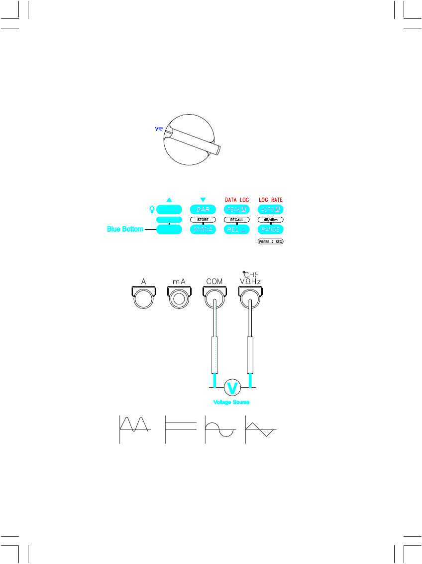
5 OPERATION
5.1 VOLTAGE MEASUREMENTS (AC, DC, AC + DC) (Set to autoranging mode
for unknown voltage measurements).
* Set dial.
* Choose AC, DC or AC + DC
* Connect leads
* The AC and AC + DC measurements provide a true RMS measurement.
* In AC mode, the frequency of the measured signal ≧20% of full scale is
displayed on sub-display.
12
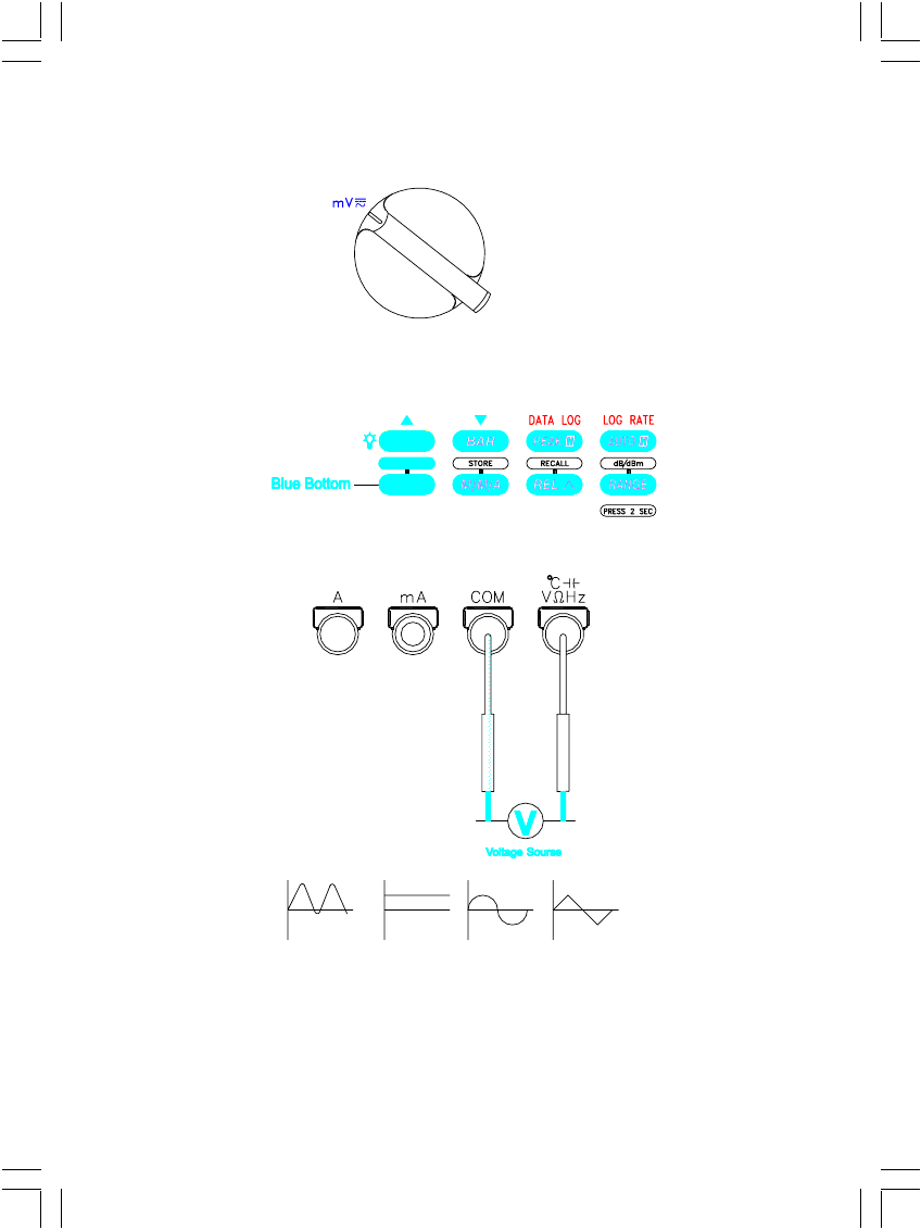
5.2 Milli VOLTAGE MEASUREMENTS (AC, DC, AC + DC)
* Set dial.
* Choose AC, DC or AC + DC
* The AC and AC + DC measurements provide a true RMS measurement.
* In AC mode, the frequency of the measured signal ≧20% of full scale is
displayed on sub-display.
*Connect leads
13
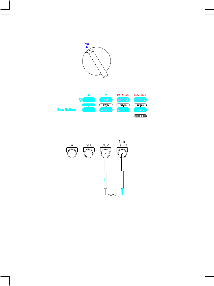
5.3 OHM AND LOW VOLTAGE OHM MEASUREMENTS
* Set dial.
* Choose Ω or LV Ω
*Connect leads
* CAUTION : Remove all power from the circuit before connecting the test
leads.
* LV setting reduces the maximum test voltage level to about 0.5V to avoid turning
on semiconductor devices.
* Remove individual components from circuitry for best results.
14
5.4 DIODE TEST
* Set dial.
CAUTION : Remove all power from the circuit before connecting the test
leads.
* Remove individual components from circuitry for best results.
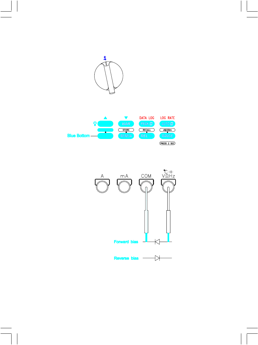
* Choose diode test.
*Connect leads
Forward bias
Good = 0.4 to 0.9V
Bad = o or = > 2.0V
Reverse bias
Good = OL
Bad = <2.0V
15
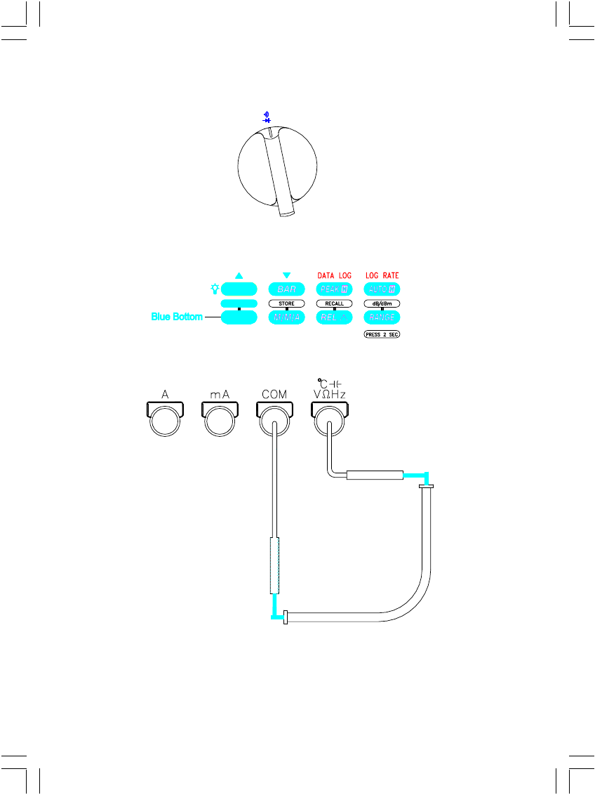
5.5 CONTINUITY CHECK
* Set dial.
CAUTION : Remove all power from the circuit before connecting the test
leads.
* The beeper sounds if the resistance of the circuit is less than 50Ω.
* Choose diode test.
*Connect leads
16
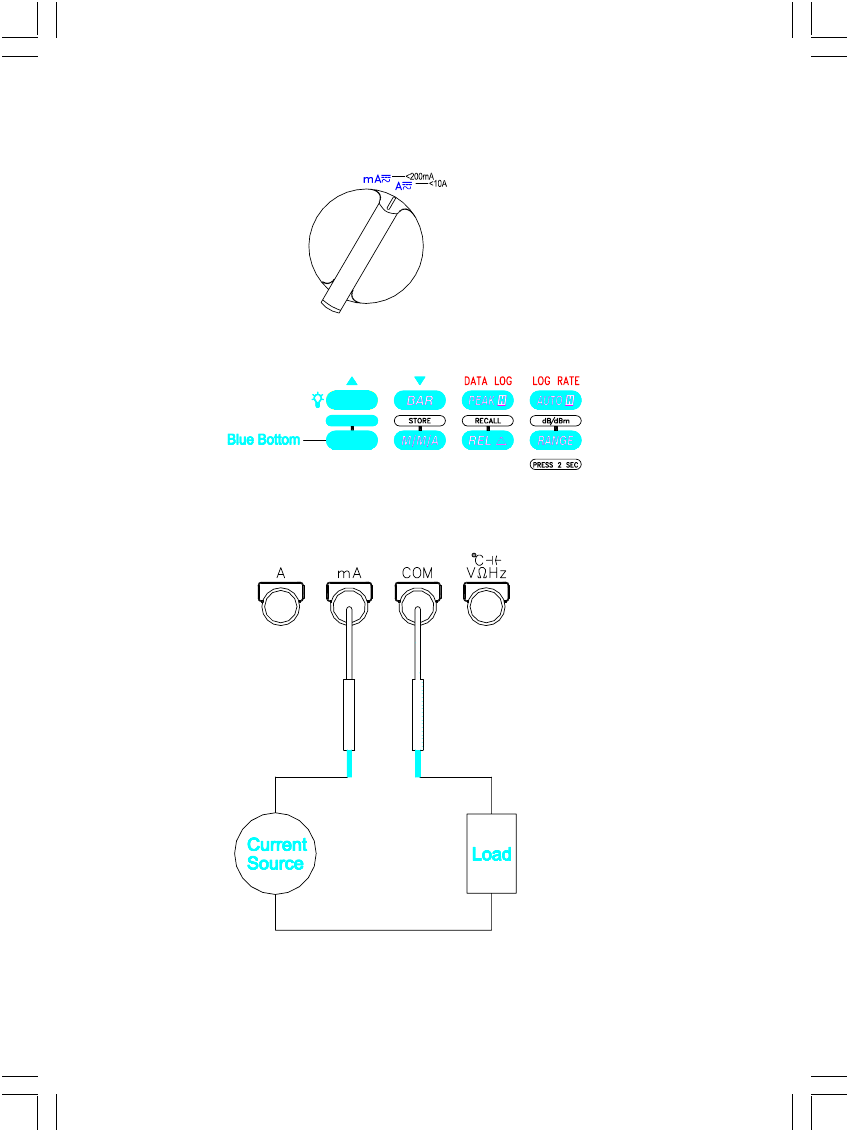
5.6 CURRENT MEASUREMENTS (AC, DC, AC +DC)
* Set dial.
* Choose AC, DC or AC + DC
* Connect leads
17
* CAUTION : Limit large current measurements ( 10 to 20A) to 30 seconds
and allow two minutes of cooling between measurements.
* Do not connect to circuits with > 600V.
* The AC and AC + DC measurements provide true RMS.
* In AC mode, the frequency of the measured signal ≧ 20% of full scale is
displayed simultaneously.
5.7 CAPACITANCE MEASUREMENTS
* Set dial.
* Connect leads, zero stray capacitance for low capacitance measurements.
* CAUTION : Remove all power from the circuit and discharge Capacitor to be
measured before connecting the test leads.
* Remove individual components from circuit for best results.
18
5.8 FREQUENCY AND DUTY FACTOR MEASUREMENTS
* Set dial.
* The duty factor displays the percent of the signal that is high.
* Choose period or duty factor on sub-display.
*Connect leads
19
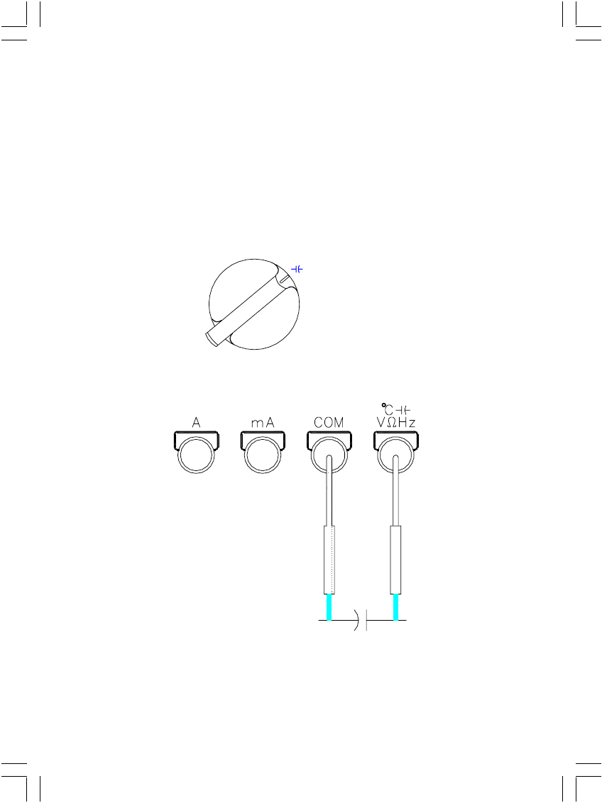
5.9 TEMPERATURE MEASUREMENTS
* Set dial.
* This setting requires an optional temperature probe and adapter. Refer to
Accessories.
* Allow about 5 minutes room temperature balance after settled for best
measurement.
* Choose Celsius or Fahrenheit.
*Connect leads

20
6. SPECIAL FEATURE DESCRIPTIONS
6.1 Auto fuse detection
The meter checks the integrity of the internal fuses for the mA, A measure-
ments.
If an open fuse is detected, ProbE is displayed and beep sounds continuously
when the correct function position and probe insertion are applied.
6.2 Probe input guard
The meter beeps continuously and displays “ProbE” if a probe is inserted in a
current input connector and a measurement other than current is selected.
6.3 Buzzer
A single beep indicates correct operation ; two beeps indicate a warning or
error condition.
7. POWER-UP OPTIONS
Press button while turning meter on from OFF position.
LIGHT : Disable backlit auto off.
RANGE : Turn off beeper.
BLUE : Disable Auto Power OFF.
AUTO H : Set temperature measurement default at °F .
M/ M/ A : Clear memory area for store.
PEAK H : Toggle 50Hz / 60Hz of line frequency.
AUTO POWER OFF : The meter turns itself off within 30 minutes if no controls
or settings are changed. Restore power by switching dial.

21
8. SPECIFICATIONS
All specifications are warranted unless noted typical and apply to the DMM 107N
and DMM 109N.
Stated accuracies are at 23°C ± 5°C at less than 80% relative humidity and
without the battery indicator displayed.
8.1 General specifications
Characteristics Description
LCD display digits 4 1/2 or 3 3/4
Bargraph segments 42 Segment Graph
Display count 20,000 or 4,000
Numeric update rate 2 times / sec (20,000 count),
4 times / sec (4000 count)
Bargraph 20 times/sec
Polarity display Automatic
Overrange display OL is displayed
Low voltage indicator is indicated
Temperature Coefficient 0.1 x (Spec.Accuracy) per °C,< 18°C
or > 28°C .
Automatic power-off time Automatic backslit off =15minutes
Power source One 9V dry cell battery
Maximum input voltage 1000V (750V AC) CAT Ⅱbetween
V and COM
Maximum floating voltage 1000V (750V AC) CAT Ⅱbetween
any terminal and earth ground
Maximum open circuit
Voltage (current inputs) 600V between A and COM and
between mA and COM
Overload protection mA connector 1A (600V) fast blow fuse
A connector 15A (600V) fast blow fuse
V connector
1100 Vp V V AC+DC
850 Vp mV mV AC+DC
LVΩ Ω Hz% DF °C °F
Battery Life 100 hours typical (alkaline)
Maximum input current 200mA between mA and COM 10A
continuous between A and COM
(20A for 30 seconds)
22
8.2 Measurement Characteristics
(All at 23°C ± 5°C ,< 80% R.H.) ±([% of reading] + [number of least digits]).
Functions with 4000-count mode divide the [ number of least digits ] by 10 when on
4000 count mode, in addition DCV to add 2 more digits on every ranges.
1. VOLTAGE :
DCV 107N 109N
20mV ± (0.06% + 60) ± (0.06% + 60)
200mV ± (0.06% + 20) ± (0.06% + 20)
2V, 20V, 200V, 1000V ± (0.06% + 10) ± (0.06% + 10)
ACV 107N 109N
20mV,200mV
40Hz ~ 100Hz
100Hz ~ 1KHz
± (0.70% + 80)
± (1.00% + 80)
± (0.70% + 80)
± (1.00% + 80)
2V
40Hz ~ 100Hz
100Hz ~ 1KHz
1KHz ~ 10KHz
10KHz ~ 20KHz
20KHz ~ 50KHz
50KHz ~ 100KHz
± (0.70% + 50)
± (1.00% + 50)
± (2.00% + 60)
± (3.00% + 70)
± (5.00% + 80)
± (10.00% + 100)
± (0.70% + 50)
± (1.00% + 50)
± (2.00% + 60)
± (3.00% + 70)
± (5.00% + 80)
± (10.00% + 100)
20V
40Hz ~ 100Hz
100Hz ~ 1KHz
1KHz ~ 10KHz
10KHz ~ 20KHz
20KHz ~ 50KHz
50KHz ~ 100KHz
± (0.70% + 50)
± (1.00% + 50)
± (2.00% + 60)
± (3.00% + 70)
± (5.00% + 80)
± (10.00% + 100)
± (0.70% + 50)
± (1.00% + 50)
± (2.00% + 60)
± (3.00% + 70)
± (5.00% + 80)
± (10.00% + 100)
200V
40Hz ~ 100Hz
100Hz ~ 1KHz
1KHz ~ 10KHz
10KHz ~ 20KHz
20KHz ~ 50KHz
± (0.70% + 50)
± (1.00% + 50)
± (2.00% + 60)
± (3.00% + 70)
± (5.00% + 80)
± (0.70% + 50)
± (1.00% + 50)
± (2.00% + 60)
± (3.00% + 70)
± (5.00% + 80)
750V
40Hz ~ 100Hz
100Hz ~ 1KHz
± (0.70% + 50)
± (1.00% + 50)
± (0.70% + 50)
± (1.00% + 50)
Bandwidth 40Hz ~ 100KHz 40Hz ~ 100KHz
23
dBm (typical) : -15 dBm to +55 dBm (0 dBm = 1mW into 600Ω).
dBv (typical) : -80 dBv to + 50 dBv (0 dBv = 1 Vrms).
Note : (ACV and AC + DCV)
Add additional 20 for reading under 0.5 time of range for 5K ~ 50KHz.
Specifications exclude under 0.4 time of range for 50KHz ~ 100KHz.
Resolution : 1µV in the 20mV range.
Input Impedance : 10MΩ, <100pF.
Overload Protection : 1000V dc, 750V rms.
AC Conversion Type : AC Coupled True RMS responding.
AC + DC Volts : Same as AC(RMS) + 1.00% + 80.
Crest Factor : +1.5% addition error for C.F. 1.4 to 3
+3.0% addition error for C.F. from 3 to 4
2. CURRENT :
DCA 107N 109N
20mA, 200mA ± (0.20% + 40) ± (0.20% + 40)
2A, 10A ± (0.20% + 40) ± (0.20% + 40)
ACA 107N 109N
20mA, 200mA, 2A,10A
40Hz ~ 500Hz ± (0.80% + 50) ± (0.80% + 50)
20mA, 200mA, 2A,10A
500Hz ~ 1KHz ± (1.20% + 80) ± (1.20% + 80)
200mA, 10A
1KHz ~ 3KHz ± (2.00% + 80) ± (2.00% + 80)
Range : 20mA, 200mA, 2A,10A.
Resolution : 1µA in the 20mA range.
Burden Voltage : 800mV max. for mA input, 1V max. for A input.
AC Conversion Type : AC Coupled True RMS responding.
Input Protection : Equipped with High Energy Fuse.
1A, 600V, IR 10KV fuse (Bussmann BBS-1 or equivalent) for
mA input.
15A, 600V, IR 100KV fuse (Bussmann KTK 15 or equivalent)
for A input.
AC + DC Current : Same as AC(RMS) + 1.00% + 80
C.F. : Same as ACV.
24
3. PEAK HOLD : +[±(0.7% + 20)] additional error for > 20% of full scale and
pulse width greater than 0.5mS; ±(10) more for 50% of full
scale on 2V range. (2000 / 4000 counts)
4. RESISTANCE :
OHM 107N 109N
200Ω, 2KΩ ± (0.30% + 30) ± (0.30% + 30)
20KΩ, 200KΩ ± (0.30% + 30) ± (0.30% + 30)
2MΩ ± (0.30% + 50) ± (0.30% + 50)
20MΩ ± (5.00% + 50) ± (5.00% + 50)
200MΩ * ± (5.00% + 20) ± (5.00% + 20)
2GΩ * ± (5.00% + ± (5.00% +
LV OHM 107N 109N
2KΩ, 20KΩ, 200KΩ ± (0.60% + 20) ± (0.60% + 30)
2MΩ ± (0.60% + 50) ± (0.60% + 50)
20MΩ * ± (7.00% + 50) ± (7.00% + 50)
200MΩ * ± (7.00% + 20) ± (7.00% + 20)
* excludes DIGIT switch.
Resolution : 0.01Ω in the 200Ω range.
Open Circuit Voltage : 3.3V
Open Circuit Low Voltage : 0.6V
Input Protection : 600V rms.
5. CONTINUITY CHECK (Excludes DIGIT switch)
Continuity Threshold : Approx. 50Ω.
Continuity Indicator : 2KHz Tone Buzzer.
Input Protection : 600V rms.
6. DIODE TEST (Excludes DIGIT switch)
Test Current : 1.1mA (Typical)
Open Circuit Voltage : 3.3V DC (max).
Input Protection : 600V rms.
25
7. CAPACITANCE (4000 counts) (Excludes DIGIT switch)
Capacitance 107N 109N
4nF, 40nF * ± (1.50% + 10d) ± (1.50% + 10d)
400nF, 4µF ± (0.90% + 5d) ± (0.90% + 5d)
40µF, 400µF ± (1.20% + 5d) ± (1.20% + 5d)
4mF,40mF ± (1.50% + 5d) ± (1.50% + 5d)
Note : For best measurements, with △ mode on nF ranges.
* With △ mode.
Range : 4nF, 40nF, 400nF, 4µF, 400µF, 4mF, 40mF
Resolution : 1pF in the 4nF range.
Input Protection : 600V rms.
8. FREQUENCY COUNTER (Excludes DIGIT switch)
Range : 20Hz, 200Hz, 2KHz, 20KHz, 200KHz, 1MHz.
Resolution : 0.01Hz in the 200Hz range.
Accuracy : ±(0.01% + 10), ±(0.01% + 50) for 20Hz Range.
Sensitivity : 0.5Vp-p, for 5Hz ~ 1MHz.
Min.Frequency : 5Hz.
Input Protection : 600V rms.
9. DUTY FACTOR (Excludes DIGIT switch)
Range : 20% ~ 80%
Resolution : 0.1%.
Accuracy : ± 1% (20Hz ~ 10KHz, 5Vp-p), ± 2% for 50% ~ 80%
10. Temperature (Excludes DIGIT switch)
Temperature 107N 109N
-100°C ~ 1200°C ± (0.1% + 3°C) ± (0.1% + 3°C)
-200°C ~ -100°C ± (0.1% + 6°C) ± (0.1% + 6°C)
Note : The readings < 360°C on 1°C resolution range when settled as manual
range, display reads “Er” to change to lower range for best measurements.
Multiply the digit accuracy by 2 for °F .
Range : -200°C ~ 1200°C.
Resolution : 0.1°C for –200°C ~ 400°C, 1°C for 400°C ~ 1200°C
Input protection : 600V rms.

26
8.3 Physical characteristics
Characteristics Description
Dimensions (H x W x D) 200mmx90mmx42mm
212mmx100mmx55mm(with holster)
Weight (with battery) 0.4Kg
With holster 0.6Kg
8.4 Environmental characteristics
Characteristics Description
Temperature operating 0 to + 50°C
Non-Operating -20 to + 60°C
Humidity (operating) < 80% R.H.
Altitude Operating 2,222 m (7290 ft.)
Non-Operating 12,300 m (40354 ft.)
Vibration & shock Operating MIL-T-28800E TYPE II Class 5
2.66gRMS, 5 to 500 Hz, 3axes
(10 minutes each)
Dust / Water Protection IP Rating IP 64.
Indoor Use
8.5 Certifications and compliances
Safety Designed to IEC 1010-1, UL3111-1 and CSA specifications
Input rating
1000V DC Category Ⅱ
600V DC Category Ⅲ
750V AC Category Ⅱ
600V AC Category Ⅲ
CAT Ⅲ : Distribution level mains, fixed installation.
CAT Ⅱ : Local level mains, appliances, portable equipment.
CAT Ⅰ: Signal level, special equipment or parts of
equipment, telecommunication, electronics.
Pollution Degree 2 Do not operate in environments where conductive pollutants
may be present.
Over voltage
category

27
Certifications and compliances (cont.)
EC Declaration
of Conformity
Meets the intent of Directive 89/336/EEC for Electtromag-
netic Compatibility and Low Voltage Directive 73/23/EEC
for Product Safety. Compliance was demonstarted to
the following specifications as listed in the official Journal
of the European Communites:
En 55011 Class A : Radiated and Conducted Emissions.
EN 50082-1 Immunity : IEC 801-2 Electrostatic Discharge
IEC 801-3 RF Radiated
EN 61010-1 Safety requirements for electrical equipment
for measurement, control, and laboratory use.

28
9. MAINTENANCE
Protect the meter from adverse weather conditions. The meter is not waterproof.
Do not expose the LCD display to direct sunlight for long period of time.
CAUTIONS. To avoid damage to the meter, do not expose it to sprays, liquids,
or solvents.
Clean the exterior of the meter by removing dust with a lint-free cloth. Use care to
Avoid scratching the clear plastic display filter.
For further cleaning, use a soft cloth or paper towel dampened with water. You
can use a 75% isopropyl alcohol solution for more efficient cleaning.
CAUTION. To avoid damage to the surface of the meter, do not use abrasive
or chemical cleaning agents.
BATTERY REPLACEMENT (refer to Figure 4)
1. Disconnect the test leads from any circuit under test and turn off meter.
2. Remove the test leads from meter.
3. Loosen the plastic screws on the battery cover.
4. Remove battery cover from case bottom.
5. Install a new battery after removing the original one.
6. Assemble battery cover onto bottom case with screw driver.
FUSE REPLACEMENT (refer to Figure 5)
1. Follow step 1 to step 4 described in Battery Replacement.
2. Remove the battery from meter.
3. Remove 3 screws installed the top case and bottom case of meter.
4. Separate the top case and PCB of meter.
5. Replace a new fuse(FUSE 1 or FUSE 2).
6. Assemble the top case and PCB of meter.
7. Assemble the top case, PCB, and bottom case of meter.
8. Install the battery removed and assemble the battery cover.
29
Battery and Fuse Replacement
WARNING : Installing improper fuses can cause injury and product damage.
Screw
Screw
Battery
Cover
Battery
Connector
9V
Battery
Figure 4
Screw
Bottom
Case
Figure 5
Fuse1
1A(600v)
Battery
Cover
Screw
Screw
Fuse2
15A(600v)
Top
Case
Figure 4
Figure 5
Screw
Screw
Battery Cover
Battery
Connector
9V Battery
Top Case
Bottom Case
Screw
Screw
Screw
Battery Cover
Fuse 1
1A (600V)
Fuse 2
15A (600V)
30
107N 109N
Gift Box • •
Meter • •
Holster + Tilt • •
Battery (9V Alkaline) • •
Manual • •
Test Leads • •
Aligator Clip • •
Temp. Socket • •
K-Type Sensor (50BK) • •
RS 232 Cable (with Adapter DB9M to DB25F) Option •
Carrying Case Option Option
10. ACCESSORIES

APPA TECHNOLOGY CORP.
9F, 119-1 Pao-Zong Rd., Shin-Tien,
Taipei, 23115, Taiwan, R.O.C.
P.O.Box. 12-24 Shin-Tien, Taiwan.
Tel : +886-2-29178820
Fax: +886-2-29170848
E-mail : info@appatech.com
Http: // www.appatech.com
Высококонтрастный ЖК-индикатор, которым оснащены модели этой серии, позволит вам без проблем считывать показания с дисплея как при ярком солнечном свете, так и, благодаря встроенной подсветке, в абсолютной темноте.


Подробное описание
Для увеличения ресурса батарей, подсветка дисплея имеет функцию автоотключения.
- Количество разрядов индикатора max 20000
- Линейная шкала
- Диапазоны измерения постоянного напряжения 200 мВ-2-20-200-1000 В
- Диапазоны измерения переменного напряжения 20-200 мВ-2-20-200-750 В
- Диапазоны измерения постоянного тока 2-200 мА-2-10 А
- Диапазоны измерения переменного тока 20-200 мА-2-10 А
- Диапазоны измерения сопротивления 200 Ом-2-20-200 кОм-2-20-200 МОм-2 ГОм
- Диапазоны измерения емкости 4-40-400 нФ-4-40-400 мкФ-4-40 мФ
- Диапазоны измерения частоты 20 Гц-1 МГц
- Диапазоны измерения температуры, С -200 1200
- Тест диодов и транзисторов
- Прозвонка цепей на проводимость
- Память предыдущих значений
- Защита от перегрузок
- Порт RS232
- Автоматическое отключение
- Размеры 98 x 197 x 50 мм
- Вес 620 г
Техническое описание цифровых мультиметров APPA серии 100 — 103N, 105N, 106, 107, 109 (pdf)
Сводная таблица технических характеристик цифровых мультиметров APPA серии 100 — 103N, 105N, 106, 107, 109
Характеристики нормируются при: (23±5) °С, отн. влажность 80%
|
Параметры |
АРРА 103N | АРРА 105N | APPA 106 | APPA 107/109 | |
| Постоянное напряжение |
Пределы измерений |
400 мВ; 4; 40; 400; 1000 В |
20; 200 мВ; 2; 20; 200; 1000 В |
||
|
Точность |
± (0,25 % + 2 ед. сч.) |
± (0,1 % + 2 ед. счета) |
±(0,06% + 10 ед. сч.) |
||
|
Разрешение |
0,1 мВ |
1 мкВ |
|||
|
Вх. сопротивление |
10 МОм |
||||
|
Защита входа |
1000 В |
=1000 В; ~750 В |
|||
|
Переменное напряжение |
Пределы измерений |
400 мВ; 4; 40; 400; 750 В |
20; 200 мВ; 2; 20; 200; 750 В |
||
|
Погрешность |
± (0,8 % + 5 ед. сч.) |
± (0,5 % + 5 ед. счета) |
± (0,7 % + 50 ед. сч.) |
||
|
Разрешение |
0,1 мВ |
1 мкВ |
|||
|
Полоса частот |
40 Гц…1 кГц |
40 Гц…100 кГц |
|||
|
Вх. импеданс |
10 МОм/100 пФ |
||||
|
Защита входа |
1000 В |
=1000 В; ~750 В |
|||
|
Относительный уровень |
Диапазон измерений |
Нет |
Нет |
Нет |
-80 дБ…50 дБ |
|
Опорный уровень |
0 дБ = 1 В0 дБм = 1 мВт, 600 Ом |
||||
|
Постоянный ток |
Пределы измерений |
40; 400 мА; 10 А |
20; 200 мА; 2; 10 А |
||
|
Точность |
± (0,6 % + 2 ед. сч.) |
± (0,4 % + 2 ед. сч.) |
± (0,2 % + 40 ед. сч.) |
||
|
Разрешение |
10 мкА |
1 мкА |
|||
|
Защита входа |
Предохранитель 15 А/600 В (вход <А>); 1 А/600 В (вход <мА>) |
||||
|
Переменный ток |
Пределы измерений |
40; 400 мА; 10 А |
20; 200 мА; 2; 10 А |
||
|
Погрешность |
± (1,2 % + 5 ед. сч.) |
± (1,0 % + 5 ед. сч.) |
± (0,8 % + 50 ед. сч.) |
||
|
Разрешение |
10 мкА |
1 мкА |
|||
|
Полоса частот |
40 Гц…1 кГц |
40 Гц…3 кГц |
|||
|
Защита входа |
Предохранитель 15 А/600 В (вход <А>); 1 А/600 В (вход <мА>) |
||||
|
Сопротивление |
Пределы измерений |
400 Ом; 4; 40; 400 кОм; 4; 40 МОм |
200 Ом; 2; 20; 200 кОм; 2; 20; 200 МОм; 2 ГОм |
||
|
Погрешность |
± (0,6 % + 3 ед. сч.) |
± (0,4 % + 2 ед. сч.) |
± (0,3 % + 30 ед. сч.) |
||
|
Разрешение |
0,1 Ом |
10 мОм |
|||
|
Тестовое напряжение |
1,3 В |
3,3; 0,6 В |
|||
|
Защита входа |
600 В |
||||
|
Прозвон цепи |
Порог срабатывания |
30 Ом |
50 Ом |
||
|
Индикация |
Непрерывный звуковой сигнал частотой 2 кГц |
||||
|
Защита входа |
600 В |
||||
|
Испытание p-n |
Макс. ток теста |
1,5 мА |
1,1 мА |
||
|
Напряжение теста |
3 В |
3,3 В |
|||
|
Защита входа |
600 В |
||||
|
Частота |
Пределы измерений |
4; 40; 400 кГц; 4; 40 МГц |
4; 40; 400 кГц; 4; 40; 400 МГц |
20; 200 Гц; 2; 20; 200 кГц; 1 МГц |
|
|
Погрешность |
± (0,01 % + 1 ед. счета) |
±(0,01 % + 10 ед. сч.) |
|||
|
Разрешение |
1 Гц |
1 мГц |
|||
|
Чувствительность |
150 мВ |
250 мВ |
|||
|
Защита входа |
600 В |
||||
|
Частота вращения |
Пределы измерений |
40; 400 коб/мин; 4; 40; 400 Моб/мин |
40; 400 коб/мин; 4; 40; 400; 4000 Моб/мин |
Нет |
|
|
Погрешность |
± (0,01 % + 10 ед. счета) |
||||
|
Разрешение |
30 об/мин |
||||
|
Чувствительность |
150 мВ |
||||
|
Защита входа |
600 В |
||||
|
Коэф. заполнения импульсов |
Диапазон измерений |
Нет |
Нет |
Нет |
20…80 % |
|
Погрешность |
± (0,1 % + 1 ед. сч.) |
||||
|
Разрешение |
0,10% |
||||
|
Емкость |
Пределы измерений |
4; 40; 400 нФ; 4; 40; 400 мкФ; 4; 40 мФ |
|||
|
Погрешность |
± (2,0 % + 8 ед. счета) |
± (0,9 % + 5 ед. сч.) |
|||
|
Разрешение |
1 пФ |
||||
|
Защита входа |
600 В |
||||
|
Температура |
Диапазон измерений |
Нет |
Нет |
-20 °С…800 °С; -4 °F…1472 °F |
-200 °С…1200 °С; -328 °F…2192 °F |
|
Погрешность |
± (1,0 % + 3 °С); |
± (0,1 % + 3 °С); |
|||
|
Разрешение |
1 °С; 1 °F |
0,1 °С; 0,1 °F |
|||
|
Защита входа |
600 В |
||||
|
Общие данные |
Измерение ср. кв. зн. |
Синусоидальный сигнал |
TRUE-RMS |
||
|
Макс. индицир-е число |
4000 |
20000 |
|||
|
Линейная шкала |
82 сегмента |
42 сег.; возможна уст-ка <0> в центр |
|||
|
Интерфейс |
RS-232 |
||||
|
Объем памяти |
Нет |
1000 |
|||
|
Объем регистратора |
Нет |
40000 (АРРА 109) |
|||
|
Скорость измерения |
Цифровая шкала: 2 изм./с; линейная шкала: 20 изм./с |
||||
|
Автовыключение |
30 мин (возможна блокировка автовыключения) |
||||
|
Источник питания |
1,5 В х 2 (тип ААА) |
9 В (тип <Крона>) |
|||
|
Срок службы батареи |
450 ч |
300 ч |
100 ч |
||
|
Условия эксплуатации |
Температура: 0 °С…50 °С; отн. влажность: не более 80 % |
||||
|
Габаритные размеры |
98 х 197 х 50 мм |
||||
|
Масса |
620 г |
||||
|
Комплект поставки |
Прибор, провода, зажим <крокодил>, батарея, защитный чехол, руководство. |
||||
|
Опции |
Прогр. WinDMM100J (АРРА 103N/105N/106), WinDMM100 (APPA 107), кабель RS-232 |
Варианты написания:
109, 109N, APPA109N, APPA 109N, , APPA109, APPA 109, 109, 109N, APPA 109N, APPA 109N, , APPA 109, APPA 109, 109 109N APPA-109N APPA 109N APPA-109 APPA 109, 109 109N APPA-109N APPA 109N APPA-109 APPA 109
На чтение 6 мин. Опубликовано
Высококонтрастный ЖК-индикатор, которым оснащены модели этой серии, позволит вам без проблем считывать показания с дисплея как при ярком солнечном свете, так и, благодаря встроенной подсветке, в абсолютной темноте.
Содержание
- Подробное описание
- Описание товара
- Замена:
- общие данные APPA 109N
- Технические характеристики APPA 109N
- Комплектность APPA 109N
Подробное описание
Для увеличения ресурса батарей, подсветка дисплея имеет функцию автоотключения.
- Количество разрядов индикатора max 20000
- Линейная шкала
- Диапазоны измерения постоянного напряжения 200 мВ-2-20-200-1000 В
- Диапазоны измерения переменного напряжения 20-200 мВ-2-20-200-750 В
- Диапазоны измерения постоянного тока 2-200 мА-2-10 А
- Диапазоны измерения переменного тока 20-200 мА-2-10 А
- Диапазоны измерения сопротивления 200 Ом-2-20-200 кОм-2-20-200 МОм-2 ГОм
- Диапазоны измерения емкости 4-40-400 нФ-4-40-400 мкФ-4-40 мФ
- Диапазоны измерения частоты 20 Гц-1 МГц
- Диапазоны измерения температуры, С -200 1200
- Тест диодов и транзисторов
- Прозвонка цепей на проводимость
- Память предыдущих значений
- Защита от перегрузок
- Порт RS232
- Автоматическое отключение
- Размеры 98 x 197 x 50 мм
- Вес 620 г
Сводная таблица технических характеристик цифровых мультиметров APPA серии 100 — 103N, 105N, 106, 107, 109
Характеристики нормируются при: (23±5) °С, отн. влажность 80%
Описание товара
APPA 109N мультиметр. Все мультиметры 100-ой серии оснащены высококонтрастным ЖК индикатором. Пользователь мультиметра сможет без затруднений считывать показания, как при дневном свете, так и ночью т.к. в приборе имеется функция подсветки. Подсветка имеет функцию автоотключения для сохранения заряда батареи.
Мультиметры этой серии могут быть предоставлены с двумя типами интерфейсов: RS-232 или USB (только 109N) для удобного и быстрого подключения к компьютеру с целью калибровки мультиметра и передачи полученной информации.
Во всех приборах APPA 100-ой серии стоят высоковольтные предохранители и предохранительные сопротивления для надежной защиты прибора от перегрузок.
В новой серии приборов батарейный отсек находится под небольшой крышкой, которую удерживает один винт, что позволяет производить “горячую” замену элементов питания.
Прибор оснащен защитным резиновым кожухом. Кожух имеет подставку, а так же отверстие для подвешивания прибора и фиксаторы для щупов. Резиновый корпус способствует дополнительной защите прибора от механических повреждений.
Эргономичный дизайн измерительных щупов с упорными кольцами, предотвращающими соскальзывание пальцев, с надёжно опрессованным проводом и наконечником из прочной стали для обеспечения продолжительного срока службы. В комплект входят съёмные зажимы типа “крокодил”. Для моделей с измерением температуры в комплекте поставляется адаптер и датчик для измерения температуры.
APPA 109N USB. Общие данные
Измерение постоянного напряжения 1 мкВ … 1000 В
Измерение переменного напряжения 1 мкВ … 750 В
Измерение постоянного / переменного ток 1 мкА … 10 А
Измерение сопротивления 0,01 Ом … 2 Гом
Измерение частоты 0,01 Гц … 1 МГц
Измерение ёмкости 1 пФ … 40 мФ
Измерение температуры -200 °С … 1200 °C
Интерфейс RS-232 с оптической развязкой
Регистратор на 1600/40000 значений
APPA 109N USB. Технические характеристики
| ПОСТОЯННОЕНАПРЯЖЕНИЕ | Пределы измерений | 20; 200 мВ; 2; 20; 200; 1000 В |
| Погрешность | ± (0,06 % + 10 ед. сч.) | |
| Макс. разрешение | 1 мкВ | |
| Вх. сопротивление | 10 МОм | |
| Защита входа | =1000 В;
750 В |
|
| ПЕРЕМЕННОЕНАПРЯЖЕНИЕ | Пределы измерений | 20; 200 мВ; 2; 20; 200; 750 В |
| Погрешность | ± (0,7 % + 50 ед. сч.) | |
| Макс. разрешение | 1 мкВ | |
| Полоса частот | 40 Гц…100 кГц | |
| Вх. импеданс | 10 МОм/100 пФ | |
| Защита входа | =1000 В;
750 В |
|
| ОТНОСИТЕЛЬНЫЙ УРОВЕНЬ | Диапазон измерений | -80 дБ…50 дБ-15 дБм…55 дБм |
| Опорный уровень | 0 дБ = 1 В0 дБм = 1 мВт, 600 Ом | |
| ПОСТОЯННЫЙ ТОК | Пределы измерений | 20; 200 мА; 2; 10 А1 |
| Погрешность | ± (0,2 % + 40 ед. сч.) | |
| Макс. разрешение | 1 мкА | |
| Защита входа | Предохранитель 15 А/600 В (вход «А»); 1 А/600 В (вход «мА») | |
| ПЕРЕМЕННЫЙ ТОК | Пределы измерений | 20; 200 мА; 2; 10 А1 |
| Погрешность | ± (0,8 % + 50 ед. сч.) | |
| Макс. разрешение | 1 мкА | |
| Полоса частот | 40 Гц…3 кГц | |
| Защита входа | Предохранитель 15 А/600 В (вход «А»); 1 А/600 В (вход «мА») | |
| ЧАСТОТА(ПРИ ИЗМЕРЕНИИ УРОВНЯ) | Диапазон измерений | 40 Гц…100 кГц |
| Погрешность Макс. разрешение | ± (0,01 % + 10 ед. сч.) 0,1 Гц | |
| Чувствительность | 1/5 от предела изм-ия | |
| СОПРОТИВЛЕНИЕ | Пределы измерений | 200 Ом; 2; 20; 200 кОм; 2; 20; 200 МОм; 2 ГОм |
| Погрешность | ± (0,3 % + 30 ед. сч.) | |
| Макс. разрешение | 10 мОм | |
| Тестовое напряжение | 3,3; 0,6 В | |
| Защита входа | 600 В | |
| ПРОЗВОН ЦЕПИ | Порог срабатывания | 50 Ом |
| Индикация | Непрерывный звуковой сигнал частотой 2 кГц | |
| Защита входа | 600 В | |
| ИСПЫТАНИЕ P-N | Макс. ток теста | 1,1 мА |
| Напряжение теста | 3,3 В | |
| Защита входа | 600 В | |
| ЧАСТОТА | Пределы измерений | 20; 200 Гц; 2; 20; 200 кГц; 1 МГц |
| Погрешность | ± (0,01 % + 10 ед. сч.) | |
| Макс. разрешение | 1 мГц | |
| Чувствительность | 250 мВ | |
| Защита входа | 600 В | |
| КОЭФ.ЗАПОЛНЕНИЯ ИМПУЛЬСОВ | Диапазон измерений | 20…80 % |
| Погрешность | ± (0, 1 % + 1 ед. сч.) | |
| Макс. разрешение | 0,1 % | |
| ЁМКОСТЬ | Пределы измерений | 4; 40; 400 нФ; 4; 40; 400 мкФ; 4; 40 мФ |
| Погрешность | ± (0,9 % + 5 ед. сч.) | |
| Макс. разрешение | 1 пФ | |
| Защита входа | 600 В | |
| ТЕМПЕРАТУРА | Диапазон измерений | -200 °С…1200 °С; -328 °F…2192 °F |
| Погрешность | ± (0,1 % + 3 °С);± (0,2 % + 6 °F) | |
| Макс. разрешение | 0,1 °С; 0,1 °F | |
| Защита входа | 600 В | |
| ОБЩИЕ ДАННЫЕ | Измерение ср. кв. зн. | Сигнал произвольной формы |
| Макс. индицируемое число | 20000 | |
| Линейная шкала | 42 сегмента; возможна установка «0» в центр | |
| Интерфейс | USB | |
| Объем памяти | 1000 | |
| Объем регистратора | 40000 | |
| Интервалы регистрации | •2 | |
| Скорость измерения | Цифровая шкала: 2 изм./с; линейная шкала: 20 изм./с | |
| Автовыключение | 30 мин (возможна блокировка автовыключения) | |
| Источник питания | 9 В (тип «Крона») | |
| Срок службы батареи | 100 ч | |
| Условия эксплуатации | Температура: 0 °С…50 °С; отн. влажность: не более 80 % | |
| Габаритные размеры | 98 х 197 х 50 мм | |
| Масса | 620 г | |
| Комплект поставки | Измерительные провода (2), зажим типа «крокодил» (2), батарея (установлена), защитный чехол, руководство по эксплуатации. Дополнительно (АРРА 106/107/109): термопара К-типа (1), адаптер термопары (1).Дополнительно (АРРА 109): программа WinDMM100, кабель RS-232, переходник DB9M-DB25F (1) | |
| Опции | Программа WinDMM100J (АРРА 103N/105N/106), WinDMM100 (APPA 107), кабель RS-232 |
Комплектация мультиметра APPA 109N USB:
Замена:
- общие данные APPA 109N
- Технические характеристики APPA 109N
- Комплектность APPA 109N
- дополнительные материалы APPA 109N
- примечание
общие данные APPA 109N
Измерение постоянного напряжения 1 мкВ … 1000 В
Измерение переменного напряжения 1 мкВ … 750 В
Измерение постоянного / переменного ток 1 мкА … 10 А
Измерение сопротивления 0,01 Ом … 2 Гом
Измерение частоты 0,01 Гц … 1 МГц
Измерение ёмкости 1 пФ … 40 мФ
Измерение температуры -200 °С … 1200 °C
Интерфейс RS-232 с оптической развязкой
Регистратор на 1600/40000 значений
Технические характеристики APPA 109N
20; 200 мВ; 2; 20; 200; 1000 В
20; 200 мВ; 2; 20; 200; 750 В
0 дБм = 1 мВт, 600 Ом
20; 200 мА; 2; 10 А1
Предохранитель 15 А/600 В (вход «А»); 1 А/600 В (вход «мА»)
20; 200 мА; 2; 10 А1
Предохранитель 15 А/600 В (вход «А»); 1 А/600 В (вход «мА»)
(ПРИ ИЗМЕРЕНИИ УРОВНЯ)
Погрешность Макс. разрешение
± (0,01 % + 10 ед. сч.) 0,1 Гц
1/5 от предела изм-ия
200 Ом; 2; 20; 200 кОм; 2; 20; 200 МОм; 2 ГОм
Непрерывный звуковой сигнал частотой 2 кГц
20; 200 Гц; 2; 20; 200 кГц; 1 МГц
4; 40; 400 нФ; 4; 40; 400 мкФ; 4; 40 мФ
-200 °С…1200 °С; -328 °F…2192 °F
± (0,1 % + 3 °С);± (0,2 % + 6 °F)
Измерение ср. кв. зн.
Сигнал произвольной формы
Макс. индицируемое число
42 сегмента; возможна установка «0» в центр
Цифровая шкала: 2 изм./с; линейная шкала: 20 изм./с
30 мин (возможна блокировка автовыключения)
Срок службы батареи
Температура: 0 °С…50 °С; отн. влажность: не более 80 %
98 х 197 х 50 мм
Комплектность APPA 109N
Измерительные провода (2), зажим типа «крокодил» (2), батарея (установлена), защитный чехол, руководство по эксплуатации. Дополнительно (АРРА 106/107/109): термопара К-типа (1), адаптер термопары (1).Дополнительно (АРРА 109): программа WinDMM100, кабель RS-232, переходник DB9M-DB25F (1)
Мультиметры цифровые APPA 100N серии: 103N, 105N, 106, 107. 109
| Наименование | Краткое описание | Карточка товара |
||
|---|---|---|---|---|
| APPA 109N (APPA) |
|
— | — |
Скачать документацию: Документация на APPA 109N (282.5 Кб)
- ru
- eng
-
ул. Плеханова 15А
![]()
Нет в наличии
| Торговая марка: | APPA |
| Срок гарантии (лет): | 2 |
| Поделиться: |
-
Характеристики
-
Комплектация
-
Библиотека
-
FAQ
| Измеряет | DCV | ACV | DCA | ACA | Сопротивление | Емкость | Частота | Температура | Прозвон цепи | Проверка диодов |
| Напряжение постоянное | 1000 В |
| Напряжение переменное | 750 В |
| Разрешение по напряжению | 0,001 мВ |
| Ток постоянный | 10 А |
| Ток переменный | 10 А |
| Разрешение по току | 1 мкА |
| Сопротивление максимум | 2000 МОм |
| Разрешение по сопротивлению | 0,01 Ом |
| Емкость максимум | 40000 мкФ |
| Разрешение по емкости | 1 пФ |
| Частота максимум | 1 МГц |
| Разрешение по частоте | 0,001 Гц |
| Базовая погрешность | 0,06 % |
| TrueRMS | Да |
| Интерфейс | RS-232 |
| Измерение температуры | Да |
| Прозвон цепи | Да |
| Проверка диодов | Да |
| Особенности | Регистратор 40000 |
| Мультиметр цифровой APPA 109N | 1 шт. |
| Защитный чехол с подставкой | 1 шт. |
| Измерительные провода ATL-3N | 2 шт. |
| Зажимы (типа “крокодил”) ТС-10N | 2 шт. |
| Источник питания (Крона 9B) | 1 шт. |
| Термопара К-типа | 1 шт. |
| Адаптер термопары | 1 шт. |
| Кабель RS-232 | 1 шт. |
| CD с программой WinDMM100 | 1 шт. |
| Магнитный держатель | 1 шт. |
| Руководство по эксплуатации | 1 шт. |
Расширенные характеристики, каталоги, брошюры
-
312.26 КБ
Новости
- Сертификация СИ
18.05.2016 г.
Дополнительные материалы (требуется регистрация)
-
Руководство по эксплуатации APPA 107N, APPA 109N (требуется регистрация)
837.02 КБ
Вопрос — ответ:
Где узнать содержание драгметаллов, срок службы СИ, ресурс наработки на отказ?
Изготовители импортных приборов является зарубежными компаниями, на которые не распространяется требование законодательства РФ и технического регулирования в сфере производства средств измерений. По аналогичной причине не указано содержание драгметаллов, срок службы СИ, а также ресурс наработки на отказ (в моточасах).
Внимание! Отсутствие ошибок и опечаток не гарантируется. В технические характеристики средств измерений неутвержденного типа производителем могут быть внесены изменения без предварительного уведомления. Соответствие важных параметров требует уточнения. Полные технические характеристики предоставляются по отдельному запросу. Нашли ошибку? Выделите мышкой и нажмите Ctrl+Enter.