7. Эксплуатация бетононасосных установок
Общие положения по эксплуатации бетононасосных установок
7.1. Эксплуатация бетононасосных установок должна производиться с соблюдением требований специальных инструкций по их применению и ремонту и в соответствии с нижеследующими указаниями.
7.2. Перед началом работы бетононасоса необходимо проверить надежность его установки, удостовериться, что количество масла и воды в резервуарах соответствует норме. При эксплуатации автобетононасоса следует проверить наличие горючего в баке и уровень масла в двигателе.
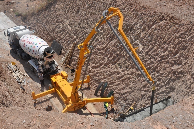
7.3. Установка автономных стрел производится в зависимости от их типа и конструктивного решения путем свободного опирания на несущие элементы конструкций (специальные фундаменты) или прикрепления к массивным частям сооружения с помощью анкеров. При любом способе закрепления этого оборудования должна быть обеспечена его устойчивость от опрокидывания в процессе работы на максимальном вылете стрелы.
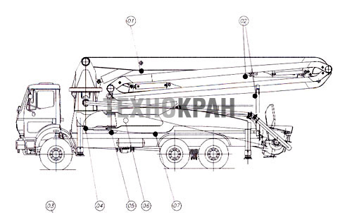
Устойчивость автобетононасосов с распределительными стрелами обеспечивается опорными стойками (аутригерами), которые при их установке в рабочее положение выдвигаются попарно с каждой стороны машины и закрепляются. Обязательным условием является выдвижение опорных стоек до отказа (рис. 33).
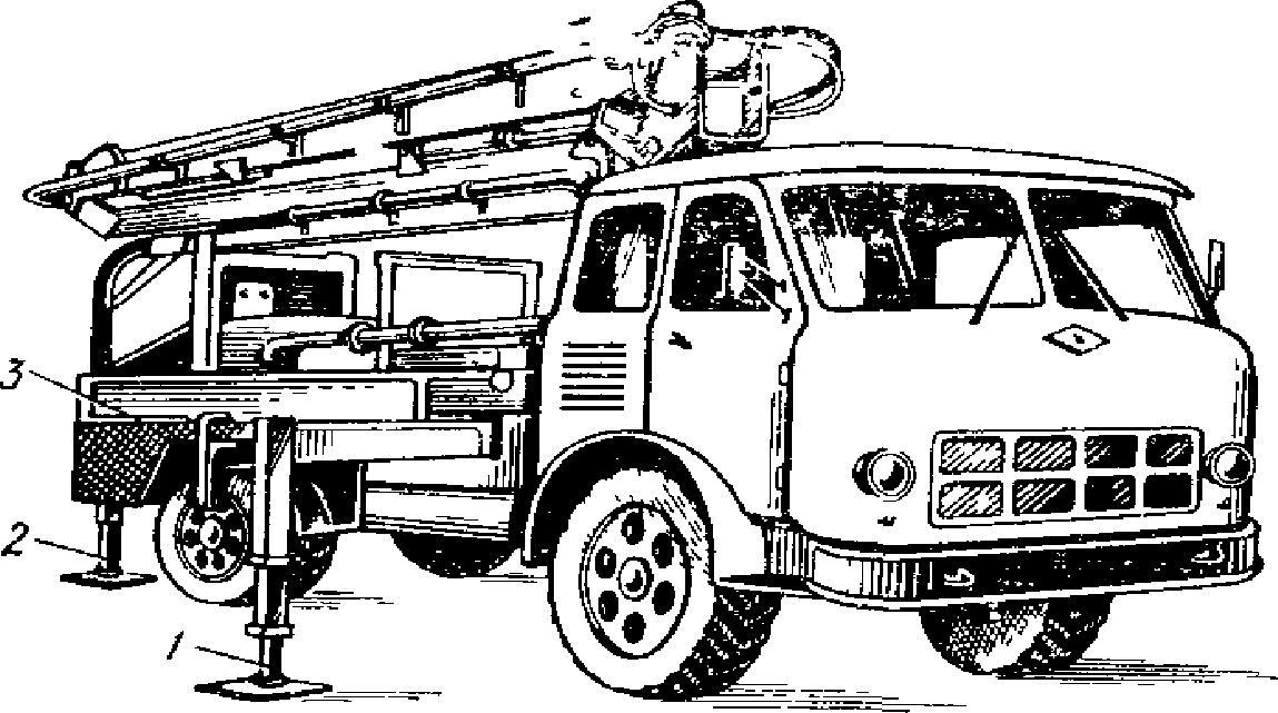
Рис. 33. Установка автобетононасоса в рабочее положение
1 и 2 — передняя и задняя опорные стойки (аутригеры);
3 — зажимное устройство для задних колес
7.4. Для обеспечения нормальной работы бетононасосной установки необходимо постоянно контролировать режим работы бетононасоса; состояние бетоновода и устройств, входящих в состав установки, показания приборов, нагрев двигателей, подшипниковых узлов, работу смесителя, уровень бетонной смеси в приемном бункере бетононасоса; уровень рабочей жидкости в баке и ее температуру и состояние соединений трубопроводов системы гидропривода.
При изменении показаний контрольно-измерительных приборов, обнаружении утечки жидкости из гидросистемы или недопустимого ее нагрева, появлении нехарактерного шума, стуков, перегрева двигателей, подшипников или нарушений герметичности бетоновода бетононасос необходимо остановить, выявить причину неисправности работы и устранить неполадки.
Большое значение для нормальной работы бетононасоса имеет заправка гидросистемы чистым маслом и своевременная проверка работы фильтров. Работа на загрязненном масле может привести к заклиниванию золотников, клапанов и др. элементов системы гидропривода, что влечет за собой длительную остановку машины и очистку бетоновода вручную.
Основные неисправности, возникающие в процессе эксплуатации бетононасосов, и способы их устранения приведены в табл. 13.
Таблица 13
|
Характер неисправности |
Возможная причина неисправности |
Способ устранения |
|
Бетононасос не включается |
Неисправность схемы электропривода |
Проверить схему электропривода |
|
При работающих насосах системы гидропривода гидроцилиндры неподвижны |
Закрыта задвижка всасывающей линии насоса. Неисправность электромагнитов предохранительных клапанов, золотников, низкое давление в гидросистеме |
Проверить состояние катушек и наличие напряжения. Отрегулировать требуемое давление в системе гидропривода |
|
При работающих насосах гидроцилиндры медленно движутся |
Недостаточный уровень рабочей жидкости в баке; в гидросистему попал воздух, утечка рабочей жидкости из трубопроводов, засорены фильтры |
Проверить уровень и долить рабочую жидкость, удалить воздух из гидросистемы, проверить трубопроводы, очистить фильтры |
|
Гидроцилиндры движутся рывками |
Недостаточный уровень рабочей жидкости, обрыв и задир внутреннего слоя гибкого рукава, внутренние утечки масла в насосе |
Проверить и долить до требуемого уровня рабочую жидкость, на неисправном гидроцилиндре поочередно заменить рукава, проверить давление масла, развиваемого насосом по манометру, выключив систему согласования |
|
Вспенивание масла |
При недостаточном уровне масла в баке из сливной трубы в бак поступает воздух |
Проверить уровень и долить масло |
|
Гидроцилиндры транспортных цилиндров работают, гидроцилиндры привода заслонок неподвижны (или наоборот) |
Неисправна система синхронизации |
Произвести регулировку в соответствии с требованиями инструкции |
|
Нагрев рабочей жидкости |
Недостаточный уровень, загрязнился фильтр сливной трубы |
Проверить уровень и при необходимости долить масло, проверить фильтр и прочистить |
|
Повышенный расход рабочей жидкости |
Наличие утечки в системе гидропривода |
Проверить состояние стыков трубопроводов, уплотнительных элементов гидроцилиндров, золотников и др. аппаратуры и устранить утечку |
|
Система гидропривода работает, гидроцилиндры транспортных цилиндров внезапно остановились. Звук изменился. При переводе на ручное управление гидроцилиндры вздрагивают или выключается система гидропривода |
Образовалась пробка в рабочей камере бетононасоса или бетоновода. Некачественная смесь, смесь расслаивается пропускаемой через неплотности манжет промывочной водой |
Прекратить прием смеси. Реверсированием работы бетононасоса попытаться откачать бетонную смесь в бункер, перемешать, перевести бетононасос на прямой ход и сделать 4 — 5 ходов для ликвидации пробки. При неудаче — найти место образования пробки и удалить, проверить качество смеси. Проверить состояние манжет поршня транспортного цилиндра и заменить |
|
Бетонная смесь вываливается из бункера |
Забита сверхмерным заполнителем виброрешетка |
Остановить бетононасос, очистить решетку от сверхмерных кусков |
|
При работе бетононасоса на режиме промывки привод цилиндров работает, бетонная смесь из бетоновода не удаляется |
Неисправность всасывающего клапана (обрыв клапана, клапан застопорен заполнителем или песком) |
Прекратить подачу воды, слить остаток воды из промывочной емкости, очистить, проверить или заменить клапан. Установить и продолжать работу |
7.5. Кроме общего наблюдения за работой всех узлов бетононасоса, дежурному оператору необходимо: следить за поступлением бетонной смеси в приемный бункер, не допуская попадания в бетононасос посторонних предметов и заполнителя, размер которого превышает 1/3 диаметра бетоновода; регулярно производить смазку движущихся частей в соответствии с требованием инструкции по эксплуатации бетононасоса; постоянно наблюдать за степенью загрязнения промывочной воды, циркулирующей в полости транспортных цилиндров. Появление цементного молока в промывочной воде свидетельствует об износе манжет поршней транспортных цилиндров. При этом вода из промывочной полости попадает в рабочую камеру, расслаивая бетонную смесь, что способствует образованию пробок в рабочей камере или в первых звеньях бетоновода.
7.6. При большой интенсивности подачи по трубам бетонной смеси (при максимальных режимах работы бетононасоса) на решетку приемного бункера целесообразно установить вибратор, который при его периодическом включении за счет побуждения бетонной смеси исключает ее «зависание» и увеличивает пропускную способность решетки.
7.7. Для предотвращения потерь бетонной смеси стенки приемного бункера бетононасоса рекомендуется наращивать резиновыми полосами.
7.8. Рабочее давление в трубопроводе при перекачивании бетонной смеси не должно превышать 80% максимального давления, развиваемого бетононасосом.
7.9. При кратковременных остановках бетононасоса целесообразно отключать его двигатель, во избежание расслоения бетонной смеси и образования пробок в трубопроводе вследствие вибрации установки.
7.10. При эксплуатации автобетононасосов их перебазировка на другую стоянку разрешается только при полностью сложенной распределительной стреле. Нарушение этого правила может повлечь за собой опрокидывание машины. Перебазировка продолжительностью не более 30 мин допускается без промывки оборудования.
7.11. При работе бетононасосных установок, оснащенных стрелами, необходимо пользоваться пультом дистанционного управления. Это позволяет оператору находиться непосредственно у места укладки бетонной смеси и точно регулировать положение стрелы и работу бетононасоса.
7.12. В случае закупорки бетоновода в процессе эксплуатации, пробки должны удаляться в соответствии с рекомендациями разд. 6.
При окончании бетонирования необходимо тщательно очистить и промыть бетоноводы и оборудование. В конце промывки бетононасоса целесообразно проконтролировать качество работ по очистке транспортных цилиндров путем дополнительного включения установки на два-три хода поршня. После этого внутреннюю поверхность бетоновода, транспортных цилиндров, приемный бункер и ряд других узлов необходимо протереть отработанным маслом.
Опорные стойки (аутригеры) автобетононасосов, зажимные и анкерные устройства убираются только при полностью сложенной стреле.
Особенности эксплуатации автономных распределительных стрел
7.13. Подготовку автономных распределительных стрел к работе необходимо производить следующим образом:
установить стрелу в рабочее положение;
зафиксировать ее положение с помощью выносных опор, анкеров или других приспособлений;
тщательно заземлить установку;
вокруг установки оставить удобные проходы;
присоединить к стреле магистральный бетоновод, а к электрошкафу управления — кабель энергосети. В случае, если диаметр магистрального бетоновода больше проложенного по стреле, то их необходимо соединить переходным конусом.
7.14. Перед пуском распределительной стрелы в эксплуатацию необходимо проверить:
исправность трубопроводов, шлангов и основных узлов; прочность и герметичность смонтированного бетоновода;
работу механизмов и узлов на холостом ходу;
наличие источника водоснабжения и исправность индивидуального центробежного насоса или компрессора для очистки бетоновода стрелы.
7.15. Перед подачей бетонной смеси включается система управления стрелой; гибкий шланг стрелы подводится к месту бетонирования (путем управления работой масляного насоса и гидравлических цилиндров с выносного пульта управления), после чего по переговорному устройству оператору бетононасоса сообщается о готовности к приему бетонной смеси.
7.16. Бетонная смесь распределяется перемещением концевого шланга стрелы к соответствующему месту бетонируемой конструкции.
Очистку бетоновода стрелы целесообразно осуществлять отдельно от магистрального трубопровода. Одновременная очистка магистрального трубопровода и бетоновода стрелы допускается в случае их одинакового диаметра и при наличии центробежного насоса или компрессора достаточной мощности (п. 6.50).
7.17. Для обеспечения безотказной работы распределительной стрелы требуется тщательный уход и обслуживание, при этом необходимо:
один раз в месяц производить смазку всех шарнирных соединений;
каждые 10 дней производить осмотр стыковых соединений с проверкой надежности затяжки болтов и гаек;
вести наблюдение за правильностью функционирования всех механизмов, гидромотора, насосной станции, цилиндров и др. При обнаружении мелких неисправностей, как, например, ослабление крепежа, течь в гидросистеме, необходимо немедленно их устранить. При неисправностях, которые нельзя устранить на месте, эксплуатацию установки необходимо прекратить;
ежедневно перед началом работы производить осмотр гидросистемы и при обнаружении течи в стыках немедленно их устранить;
вести наблюдение за исправностью электроаппаратуры и за состоянием токоведущих проводов.
7.18. При завершении работ на данном объекте распределительную стрелу необходимо сложить в транспортное положение и установить ее в месте хранения на деревянных подкладках. Все шарнирные и резьбовые соединения очистить от бетона и грязи и смазать антикоррозионной смазкой.
7.19. Замену масла в гидросистеме стрелы необходимо производить в соответствии с требованиями паспорта-инструкции по эксплуатации стрелы.
7.20. Транспортировать автономную распределительную стрелу следует в собранном виде (в транспортном положении), при этом секции стрелы должны быть надежно зафиксированы против смещения.
Для транспортирования стрелы применяются серийные прицепы соответствующей грузоподъемности.
Обслуживание и ремонт бетононасосных установок
7.21. Техническое обслуживание и ремонт бетононасосных установок являются взаимосвязанными операциями, направленными на поддержание работоспособности оборудования, и должны выполняться в соответствии с требованиями специальной инструкции по эксплуатации.
Износ деталей бетононасосов влечет за собой потерю первоначальных качеств машины, снижение производительности, вызывает повышенный расход электроэнергии, рабочей жидкости и т.п. Несвоевременная замена изношенных деталей может явиться причиной аварий и привести к длительным простоям при внеплановых ремонтах. Поэтому работа бетононасосов будет наиболее эффективной при строгом соблюдении правил технической эксплуатации и ремонтов.
7.22. Для поддержания бетононасосных установок в рабочем состоянии необходимо систематически выполнять ежесменное техническое обслуживание ЕО и техническое обслуживание ТО, а также производить планово-предупредительные ремонты ППР в соответствии с требованиями инструкции СН 207-68.
В состав ЕО входят работы по наружной очистке и промывке бетононасоса, очистке рабочей камеры, приспособлений и устройств бетоновода от бетонной смеси, смазке основных узлов, устранению утечек, доливке и смене рабочей жидкости, проверке технического состояния фильтров, подтяжке креплений, проверке регулируемых узлов, состояния гидро- и электроаппаратуры, проверке состояния бетоновода, работы по контрольному осмотру перед передачей машины при смене бригад. Замеченные неисправности записываются в журнал передачи смен.
7.23. При ежедневном техническом обслуживании обслуживающий персонал после очистки и промывки бетононасоса должен выполнить следующие операции:
1) проверить и устранить места утечки рабочей жидкости. Для этого до остановки бетононасоса осматриваются места подсоединения маслопроводов к гидроцилиндрам, соединения трубопроводов, линии разъема крышек и корпуса распределителей, насосов, гидроцилиндров и других элементов гидроаппаратуры. Подтяжка соединений производится только при выключенном бетононасосе. Для выявления мест утечек при работе на холостом ходу давление рабочей жидкости в системе гидропривода необходимо понизить до минимально возможного (3,0 — 4,0 МПа);
2) проверить положение гибких маслопроводов. Они не должны касаться друг друга и деталей бетононасоса;
3) проверить уровень рабочей жидкости в баке и при необходимости долить;
4) проверить состояние уплотнений транспортных цилиндров и деталей распределительного устройства, заменить воду в системе промывки транспортных цилиндров;
5) устранить неплотность в местах соединений стыков звеньев бетоновода, замеченную в процессе промывки, очистить и промыть всасывающий клапан;
6) произвести смазку бетононасоса согласно карте смазки;
7) проверить состояние регулируемых узлов, подтянуть крепления разъемных соединений, подготовить машину для передачи следующей смене с записью замеченных недостатков в журнале передачи смен.
7.24. ТО представляет собой комплекс мероприятий, направленных на борьбу с износом деталей, увеличение срока службы и надежности работы, а ремонт ликвидирует последствия износа заменой или восстановлением тех деталей, которые уже не могут обеспечить нормальную работу бетононасосной установки. Для самоходных бетононасосов дополнительно выполняется объем по техническому обслуживанию автомобилей.
Техническое обслуживание, кроме операций ЕО, включает номенклатуру работ, выполнение которых является обязательным: ревизия транспортных цилиндров, распределительной части и приемного бункера с целью установления степени износа уплотнительных элементов, подшипников, и других деталей с составлением перечня замены и уточнения объема работ последующего ремонта: ежедневный осмотр бетоновода, быстроразъемных соединений стыков с целью замены неисправных; замена рабочей жидкости и промывка, бака, фильтров. При необходимости выполняются работы по замене изношенных деталей.
7.25. При текущем ремонте Т выполняют все работы, предусмотренные ТО, и производится разборка транспортных цилиндров, распределительного устройства, приемного бункера для замены уплотнительных элементов, заслонок, лопастей. При необходимости производят замену манжет поршней и штоков. Производится испытание насоса главного гидропривода на расход и давление рабочей жидкости.
В процессе текущего ремонта устраняются неисправности основных узлов бетононасоса, препятствующие дальнейшей нормальной его эксплуатации. Кроме этого, уточняется объем работ последующего ремонта.
Текущий ремонт гидропривода производится по мере выявления неисправностей в работе отдельных узлов в процессе ЕО и ТО. Текущий ремонт системы гидропривода включает в основном следующие виды работ: замена уплотнительных колец в соединенных трубопроводах, в стыковых соединениях насосов, распределителей, клапанов, гидроцилиндров. В гидроцилиндрах производится также замена грязесъемника, манжет и упорных шайб. Производится заварка трещин трубопроводов, маслобака, замена фильтров и др.
7.26. Для текущего ремонта бетононасосов на местах работы рекомендуется использовать передвижные ремонтно-механические мастерские, оснащенные необходимым оборудованием и приспособлениями. С их помощью могут выполняться ТО, аварийные и заявочные ремонты.
7.27. При капитальном ремонте бетононасос в заводских условиях полностью разбирается, производится ремонт базовых деталей, восстанавливаются начальные допуски и посадки сопрягаемых поверхностей в соответствии с требованиями технической документации и указаний на производство капитального ремонта, восстанавливается чистота обработки поверхностей, заменяются изношенные агрегаты насосной части, бетоновода, электро- и гидропривода новыми или заранее отремонтированными, а также производится модернизация отдельных узлов бетононасоса.
Техника безопасности при применении бетононасосных установок
7.28. При применении бетононасосов необходимо строгое соблюдение общих правил по технике безопасности для строительных работ согласно СНиП III-А.11-70.
7.29. К управлению бетононасосами допускаются только машинисты-операторы, имеющие удостоверение на право работы на данном типе машины.
7.30. Инструктаж по технике безопасности машинистов-операторов бетононасосов проводится администрацией управления механизации совместно с администрацией строительства.
7.31. При работе бетононасосов на стройплощадке нельзя допускать:
передвижения бетононасосов со стрелой, не установленной в транспортном положении;
установку бетононасосов на опорные стойки без наличия прочных прокладок, уложенных на твердое основание;
установку бетононасосов на свеженасыпанном, неутрамбованном грунте.
7.32. Установка и перемещение бетононасосов на краю откосов котлованов, траншей, канав и других выемок допускается лишь при условии соблюдения расстояний, указанных в табл. 14.
Таблица 14
|
Глубина выемки, м |
Грунт ненасыпной |
||||
|
песчаный и гравийный |
супесчаный |
суглинистый |
глинистый |
лессовый сухой |
|
|
Наименьшее допустимое расстояние по горизонтали от подошвы откоса выемки до ближайших опор машины, м |
|||||
|
1 |
1,5 |
1,25 |
1 |
1 |
1 |
|
2 |
3 |
2,4 |
2 |
1,5 |
2 |
|
3 |
4 |
3,6 |
3,25 |
1,75 |
2,5 |
|
4 |
5 |
4,4 |
4 |
3 |
3 |
|
5 |
6 |
5,3 |
4,75 |
3,5 |
3,5 |
7.33. При монтаже бетононасосной установки необходимо тщательно заземлить электрическую систему бетононасоса, испытать бетоновод при гидравлическом давлении, в 1,5 раза превышающем рабочее. Замковые соединения бетоновода перед подачей бетонной смеси очистить и плотно закрыть.
7.34. Открытые передачи и движущиеся части машины и механизмов, входящих в бетононасосную установку (приемный бункер, электродвигатели, механическое оборудование, электрокабели), должны быть защищены специальными щитками. Работа бетононасоса со снятыми ограждениями запрещается.
7.35. Смазка механизмов и прочие операции по обслуживанию бетононасосной установки должны производиться только сменным мастером или в присутствии помощника.
7.36. Рубильники включения электродвигателей должны быть закрытого типа. По окончании работы их необходимо выключить и запереть на замок. Они включаются и выключаются сменным оператором или его помощником.
7.37. Включение и выключение рубильников для приведения в действие вибратора на виброрешетке производятся специально инструктированным рабочим бетонщиком, обслуживающим приемку бетонной смеси.
Посторонние лица к этим операциям не должны допускаться.
До пуска бетононасосной установки в работу необходимо проверить исправность заземления всей электрической части и всех основных узлов бетононасоса и вспомогательного оборудования на холостом ходу.
7.38. Электромонтажные и ремонтные работы по электрооборудованию, а также электросиловой и осветительной сети должны выполняться только электромонтерами, снабженными необходимыми инструментами, резиновыми перчатками и резиновой обувью и соответственно проинструктированными.
7.39. Работу бетононасоса без исправно действующей звонковой или световой сигнализации, либо телефонной связи между оператором бетононасосной установки и мастером бетонируемого объекта не следует допускать.
7.40. Ежедневно перед началом смены необходимо проверять исправность всех манометров бетононасосной установки, предохранительных клапанов, предупреждающих появление в ней давления выше допускаемого. В гидросистеме распределительной стрелы должны быть проверены предохранительные устройства (например, гидрозамки) для предотвращения ее падения.
7.41. Перегибание шлангов, по которым транспортируется бетонная смесь, запрещается. Закрепление гибких шлангов на штуцерах бетоноводов должно осуществляться хомутами на болтах. Применение проволоки для этой цели запрещается.
7.42. Над трубопроводами, уложенными в местах постоянного движения людей или транспортных средств, следует устраивать мостики.
7.43. При монтаже бетоноводов на высоких отметках или над котлованами должны быть установлены ограждения всех мест работы монтажников или обслуживающего персонала.
7.44. Для использования виброхоботов, вибролотков и вибропитателей для распределения бетонной смеси, подаваемой бетононасосами, должна быть обеспечена безопасность работающих от поражения электротоком. Электропровода от электродвигателей и вибраторов до рубильника заключаются в резиновые шланги.
7.45. Лотки, хоботы и виброхоботы для спуска бетонной смеси в конструкцию, а также загрузочные воронки должны быть прочно прикреплены к надежным опорам.
Для предупреждения падения бетонной смеси из загрузочной воронки бетононасоса на уровне верха воронки следует предусматривать настил или козырьки из полос резины.
7.46. Очистку бетоноводов сжатым воздухом не следует допускать, если их очистка и промывка могут быть выполнены водой.
При очистке бетоноводов сжатым воздухом должны соблюдаться следующие мероприятия:
1) у выходного отверстия бетоновода необходимо установить, кроме козырька отражателя, деревянный щит, слегка наклоненный в сторону бетоновода, при этом все рабочие должны быть удалены от выходного отверстия бетоновода на безопасное расстояние (но не менее 10 м);
2) очистку бетоноводов нужно производить при помощи 2 — 3 пыжей из пористой резины или мешковины, тщательно смоченных водой;
3) краны воздуховодов и манометр должны находиться под непрерывным наблюдением оператора, который обязан следить за равномерностью подъема давления в бетоноводе;
4) перед пуском сжатого воздуха бетоновод нужно тщательно проверить и стянуть клиньями все замковые соединения;
5) отдельные звенья бетоновода, особенно колена, должны быть испытаны на прочность соединений в стыках посредством сильного обстукивания. Появившиеся вмятины свидетельствуют об износе стенок. Такие звенья необходимо заменить;
6) воздух должен подаваться в бетоновод медленно и равномерно, чтобы пыжи выходили из конечного выходного отверстия бетоновода плавно.
7.47. При работе бетононасосных установок с распределительными стрелами необходимо учитывать следующее:
1) эксплуатация стрелы не допускается до тех пор, пока бетононасос не установлен на опоры;
2) стрела должна эксплуатироваться при силе и скорости ветра, не превышающих пределов, указанных в паспорте-инструкции по применению установки;
3) радиус вращения стрелы — опасная зона;
4) скорость поворота стрелы не должна превышать 0,5 об/мин;
5) запрещается использование концевого шланга на стреле бетононасоса большей длины, чем обозначена в паспорте-инструкции к нему.
7.48. При применении автобетононасосов необходимо обеспечить требуемое техническое состояние узлов, механизмов и приборов машин, влияющих на безопасность движения.
7.49. Для обеспечения безопасных проходов расстояние между выступающими частями бетононасоса и другими предметами должно быть не менее 1 м.
7.50. Запрещается производство бетонных работ с помощью бетононасосов без присутствия технического руководства на строительной площадке, а также применение методов и приемов работ, не соответствующих назначению и технической характеристике машины.
7.51. Возобновление работы бетононасоса после его даже незначительной остановки должно сопровождаться предупредительным сигналом мастеру бетонных работ и обратным сигналом, подтверждающим готовность принять бетонную смесь.
7.52. При работе в темное время суток дороги, проходы, а также все рабочие места должны быть освещены в соответствии с требованиями норм электрического освещения строительных и монтажных работ (СН 81-60).
7.53. Производство работ вблизи линий электропередач допускается с соблюдением правил технической эксплуатации электроустановок потребителей вдоль воздушных линий электропередач (ЛЭП), устанавливающих величину охранной зоны.
7.54. Осмотр и ремонт бетононасоса или стрелы, разъединение нагнетательного трубопровода допускается производить только после остановки бетононасоса, снятия давления в бетоноводе и отключения установки от электросети.
7.55. Запрещается ликвидировать пробки, увеличивая давление в системе выше допустимого.
7.56. Операторы бетононасоса и бетонщики должны обязательно носить защитные шлемы. Разъединение бетоноводов производить в защитных очках.
Скачать документ целиком в формате PDF
Машины
для транспортирования
бетонной
смеси и растворов.
Бетононасосы
и пневмонагнетатели.
Способ
доставки бетонов и растворов от
смесительной установки к месту их
укладки и необходимое для этого
оборудование выбирают в зависимости
от характера сооружения, общего объёма
укладываемой смеси, суточной потребности
в смеси, высоты её подъёма и дальности
горизонтального перемещения.
Дальность
подачи смеси бетононасосами по
горизонтальному бетоноводу достигает
400м,
по вертикали – 70м.
Монтируя последовательно ряд бетононасосных
установок, можно увеличить дальность
и высоту подачи.
При
любом способе транспортирования смесь
должна предохраняться от расслаивания
на составные части.
В
большинстве случае при выполнении
больших объёмов бетонных работ
экономически целесообразно транспортирование
бетонной смеси по трубам при помощи
бетононасосов. При необходимости
транспортирования бетона от центральных
бетонных установок на удалённые
строительные объекты лучшими транспортными
средствами, обеспечивающими сохранение
качества бетона, являются автобетономешалки.
а
б
в
г
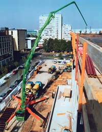
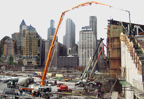
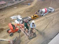
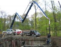
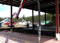
Рис.1.
Автобетононасосы
в работе:
а
— монолитное строительство; б
—
строительство стены, укрепление откоса;
в
– заливка фундамента; г
– заливка полов.
В
современных технологиях строительства
важнейшую роль играет повышение
производительности работ, экономия
времени, рабочей силы, и в конечном
счете, финансовых затрат. Использование
механизированного оборудования позволяет
решить эту задачу. Одним из видов
профессиональной строительной техники
является бетононасос.
Назначение
этой установки — транспортировка
приготовленной бетонной смеси
непосредственно к месту ее заливки с
применением бетоновода, состоящего из
отдельных секций с быстроразъемными
соединениями и специальных распределительных
стрел.
Подача
бетона по трубам при возведении монолитных
сооружений по сравнению с его подачей
ленточными конвейерами или кранами
повышает производительность труда и
снижает себестоимость работ. Такой
способ транспорта бетона позволяет
работать в стеснённых условиях и
труднодоступных местах, где другие виды
подачи не могут быть применены.
Бетононасос
– это машина для нагнетания бетонной
смеси к месту её укладки (в пределах
строительной площадки) для оперативного
и качественного строительства
разнообразных объектов с помощью гибкого
бетоновода, что также дает возможность
для нагнетания бетона в различные
плоскости.
Считается,
что подача бетона с помощью бетононасосов
существенно улучшает качество
укладываемого бетона. Это объясняется
тем, что при передаче раствора бетона
осуществляется дополнительное
перемешивание, что повышает структуру
укладываемого бетона.
Классификация:
А).
Конструктивно,
в зависимости от назначения, бетононасосы
подразделяются
на три
основные категории:
1)
–
автобетононасос;
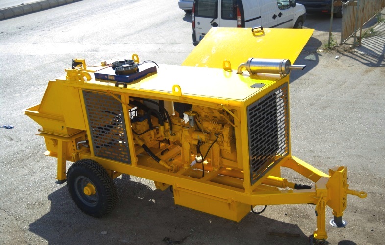
2)
—
стационарный прицепной бетононасос;
3)
—
автобетононасос со смесителем.

а
б
в
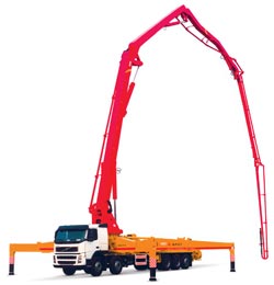
Рис.2.
Бетононасосы:
а
— стационарный прицепной бетононасос;
б
– автобетононасос;
в
— автобетононасос со смесителем (АБНС-29).
Автобетононасосы
– это строительное оборудование,
предназначенное для подачи бетона к
месту укладки, как в горизонтальном,
так и в вертикальном положении.
Автобетононасос устанавливается на
автомобильные шасси и состоит из
раздаточной стрелы, системы опоры и
бетононасоса. В зависимости от марки
автобетононасоса, длина стрелы
бетононасоса может меняться в большую
или меньшую сторону.
Производительность
автобетононасоса может достигать до
200
м³/час,
а высота подачи бетона до 48
метров.
Некоторые модели автобетононасосов
могут вращаться вокруг вертикальной
оси или оснащаться миксерами для
перемешивания бетона. В целом же
функциональных возможностей даже самого
простого автобетононасоса вполне
хватает для укладки бетона на довольно
большие площади.
Управление
работой автобетононасоса может
осуществляться либо из кабины водителя,
либо с пульта, установленного на
автомобильные шасси. Работу автобетононасоса
можно контролировать и с помощью пульта
дистанционного управления. Такой пульт
может передавать сигналы по радио или
кабелю, подключённому к автобетононасосу.
Подача
материала из автобетононасоса производится
по специальной трубе, которая называется
бетоновод. Бетоновод надёжно крепится
к раздаточной стреле автобетононасоса,
что полностью исключает потери материала
в процессе подачи к месту укладки. Если
укладку бетона планируется проводить
в зимнее время, бетоновод следует
утеплить или обогреть паром.
Стационарный
бетононасос
– спецтехника, которая, в основном,
предназначена для строительства
многоэтажных зданий. Для более дальней
подачи бетонной смеси на бетононасосе
устанавливается стрела (труба).
Стационарные агрегаты подачи бетона
(бетононасосы) отличаются следующими
техническими характеристиками:
производительность от 15
до 85
м³/час;
подача бетонной смеси может осуществляться
до 150
метров
по вертикали, и до 450
метров
по горизонтали. Работа стационарных
бетононасосов может обеспечиваться
двигателями, работающими как на дизельном
топливе, так и электричестве.
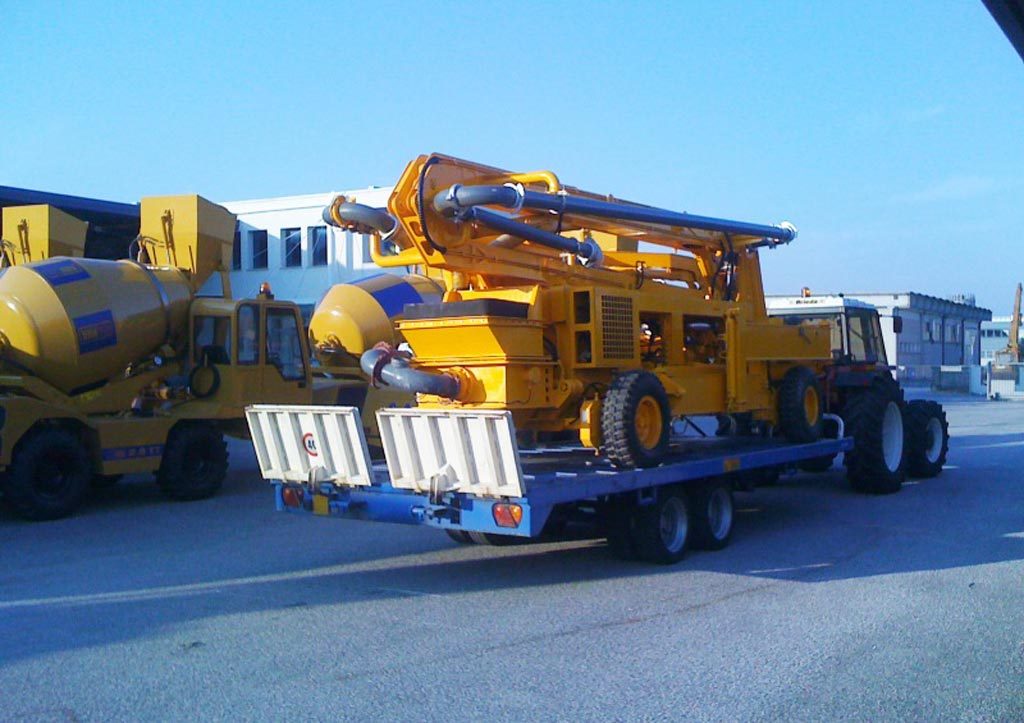
Они
предназначаются для объектов с малым
объёмом работ и представляют собой
лёгкие мобильные машины на колёсном
ходу или салазках.
Передвижные
смесители используются при небольших
объемах строительных и ремонтно-строительных
работ (с
небольшим объёмом замеса)
на рассредоточеных объектах, представляют
собой лёгкие мобильные машины на колёсном
ходу или салазках; а стационарные входят
в состав технологических линий
бетонорастворосмесительных установок
средней и большой производительности
бетонных и растворных заводов.
Стационарные
отличаются большей мощностью, однако
не имеют стрелы для подачи бетонной
смеси.
Б).
По
типу привода:
■ кривошипно-шатунные;
■ гидравлические
бетононасосы;
■ пневматические
бетононасосы.
В).
По
количеству цилиндров:
■ одноцилиндровые;
■ двухцилиндровые.
Г).
По
мобильности:
■ стационарные;

■ автобетононасосы.


Наиболее
эффективно использование бетононасоса
в следующих случаях:
• повышение
производительности труда при многоэтажном
строи-
тельстве;
• бетонирование
площадок, где в силу разных причин
затруднена
подача
бетона;
• бетонные
работы на высоте;
• имеются
препятствия, мешающие подъезду
автобетоносмесителя
и
др.
Технологический
процесс работы бетононасосов выглядит
следующим образом: бетон , по бетоноводам
поступает к месту укладки. Расстояние
и высота могут быть различными. Регулятор
оборотов, в зависимости от характеристик
бетона и расстояния, на которое
осуществляется перекачка, автоматически
устанавливает режим работы. Также
учитывается и температура воздуха.
Бетон перемешивается с помощью реверсной
системы.
Главные
достоинства бетононасосов:
выносливость и стабильность работы.
Технические характеристики позволяют
оборудованию работать в экономном
режиме. Т.к. оборудование может
использоваться круглый год, в том числе
в зимнее время, на бетононасосах
установлена система подогрева дизельного
топлива. Для защиты двигателя от перегрева
установлен агрегат, охлаждающий масло.
Обслуживать
бетононасосы несложно. Достаточно
использовать промывочный насос с водяным
пистолетом.
Общее устройство бетононасосов
Бетононасосы
поршневого типа
(с механическим приводом). Отечественная
промышленность выпускает бетононасосы
поршневого типа производительностью
10, 20 и 40м3/час
с механическим и гидравлическим приводом.
Привод
от ДВС:
Принцип
работы бетононасоса заключается в
следующем: поступающая в приёмный бункер
6
бетонная смесь подвергается непрерывному
перемешиванию лопатками 5,
для того чтобы сохранить её однородность
и предупредить расслоение. Из бункера
смесь при помощи побудителя 7,
выполненного в идее лопастной мешалки.
Поступает через всасывающий клапан 8
в цилиндр 11
насоса.
Поршень
12
насоса совершает возвратно-поступательное
движение при помощи кривошипно-шатунного
механизма, коленчатый вал 2
которого приводится во вращение от
основного электродвигателя бетононасоса.
Движение поршня строго согласовано с
положением всасывающего 8
и нагнетательного 9
клапанов: при всасывающем движении
поршня (рис.а)
клапан 8
открывается, а клапан 9
закрывается; при нагнетательном положении
поршня (рис.б)
клапан 8
закрывается , а клапан 9
открывается. Синхронизация перемещений
поршня и клапанов достигается при помощи
кулисного механизма 1,
получающего качательное движение от
профильных кулаков на коленчатом валу,
и двух тяг 3
и 4,
связывающих каждую из кулис с клапанами.
Во время всасывающего движения поршня
бетонная смесь поступает в полость
цилиндра, а во время нагнетательного
движения выталкивается в трубопровод
10.
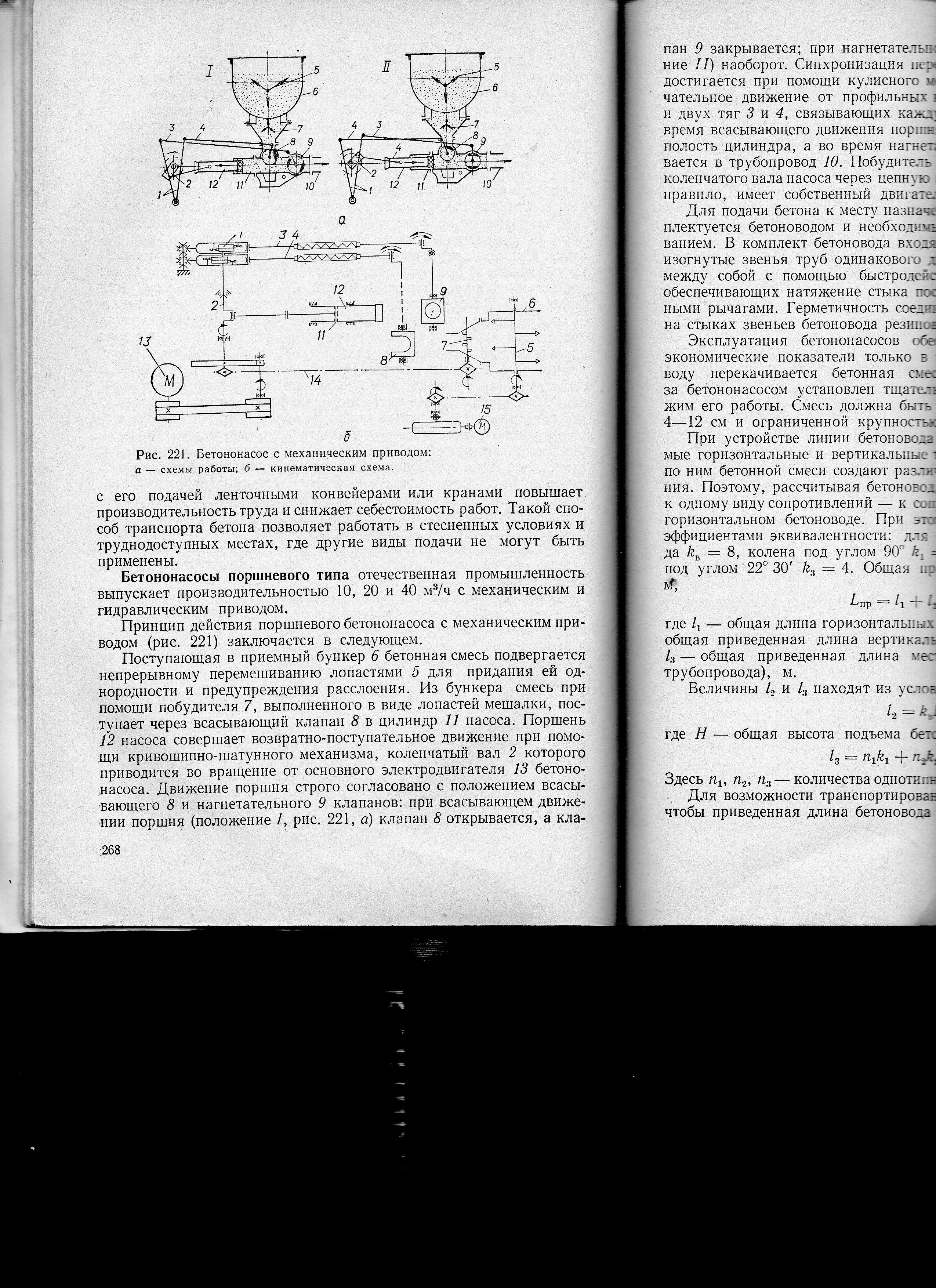
Рис.3.
Бетононасос с механическим приводом:
а
–
схема работы; б
— кинематическая схема;
І
–
всасывающее положение поршня; ІІ
–
нагнетательное положение поршня;
1
– кулисный механизм; 2
– коленчатый вал КШМ; 3
и
4
— тяги; 5
— лопасти; 6
– приёмный бункер; 7
— побудитель; 8
— ;всасывающий клапан; 9
– нагнетательный клапан; 10
— трубопровод; 11 – цилиндр насоса; 12 –
поршень насоса.
Привод
от электродвигателя:
Бетононасосы
монтируются на сварной раме 15,
снабжённой лыжами 16
для возможности перемещения бетононасоса
на небольшие расстояния. Приёмный бункер
6
делается сварным из листовой стали, а
его внутренняя поверхность футеруется
сменными броневыми листами, защищающими
стенки бункера от износа. К бункеру
прикреплена верхняя площадка 20,
на которой монтируется привод 3,
4
и 5
вала смесителя 7
и крепится пускорегулирующее
электрооборудование 2
главного
привода. С этой площадки производится
наблюдение за поступлением в бункер
бетонной смеси. В нижней переходной
воронке бункера. В непосредственной
близости к всасывающему клапану,
установлен вал 8
побудителя. Привод вала побудителя
осуществляется с помощью цепной передачи
21,
27
от коленчатого вала 18.
Рабочая
часть бетононасоса состоит из клапанной
коробки 12
и цилиндра 13,
в котором перемещается поршень 17.
Внутренняя поверхность клапанной
коробки футеруется (футеровка
– это
специальная отделка для обеспечения
защиты поверхностей от возможных
механических или физических повреждений)
сменными втулками из износоустойчивой
стали, а цилиндр – вставной гильзой.
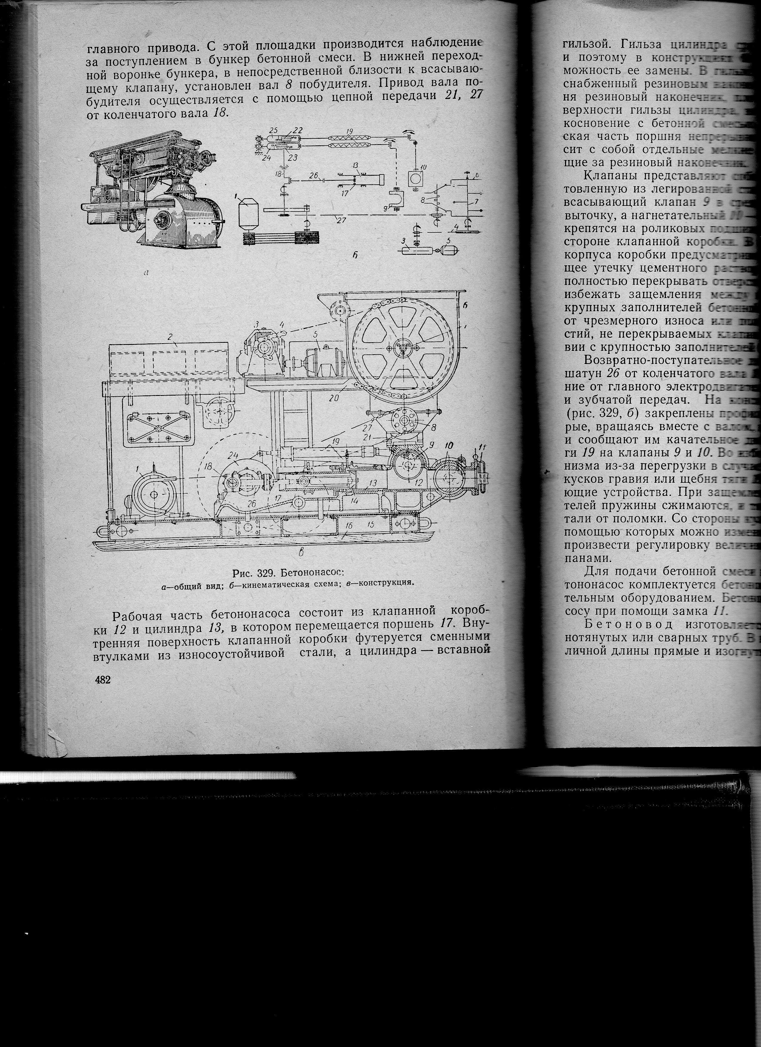
Рис.4.
Бетононасос:
1
– главный электродвигатель; 2
– пускорегулирующее оборудование
главного привода;
3
; 4
и 5
– привод вала смесителя; 6
– приёмный бункер; 7
— смеситель; 8
– вал возбудителя; 9
– всасывающий клапан; 10
– нагнетательный клапан; 11
— ; 12
– клапанная коробка; 13
— цилиндр; 14
–
резиновый наконечник; 15
– сварная рама; 16
— лыжи; 17
— поршень; 18
– коленчатый вал; 19
— тяга; 20
– верхняя площадка; 21
и 27
– цепная передача; 22
и 23
– профилированные кулаки; 24
и 25
— кулисы; 26
— шатун.
Гильза
цилиндра сравнительно быстро изнашивается


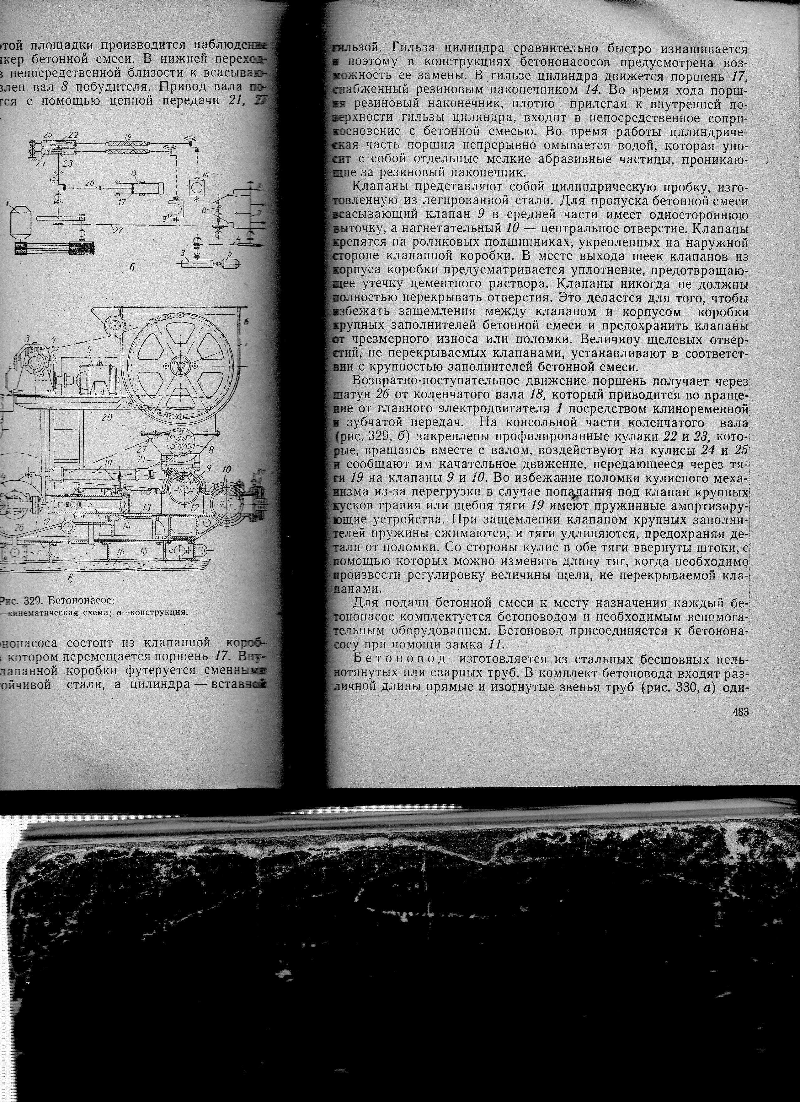
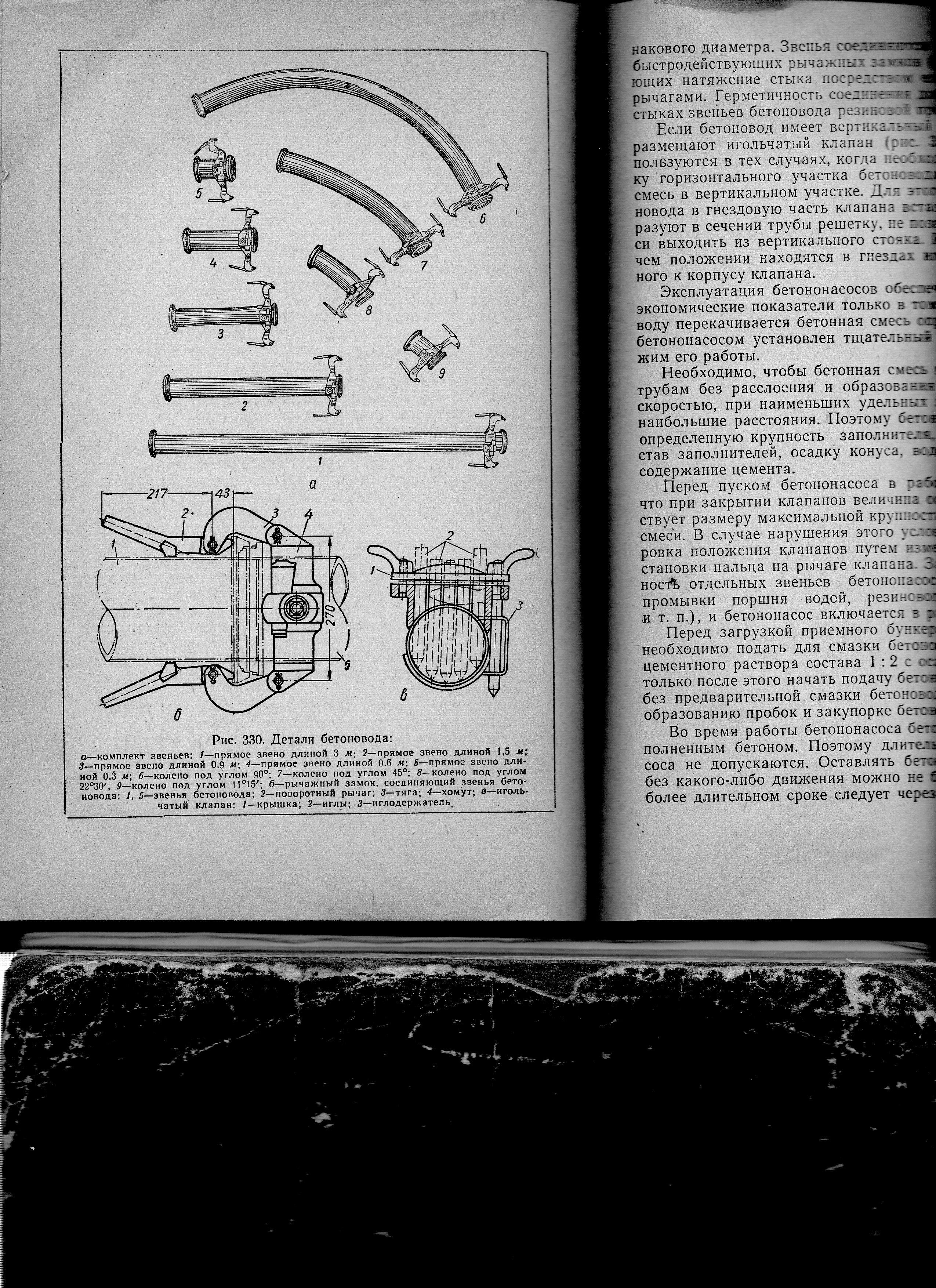
Рис.5.
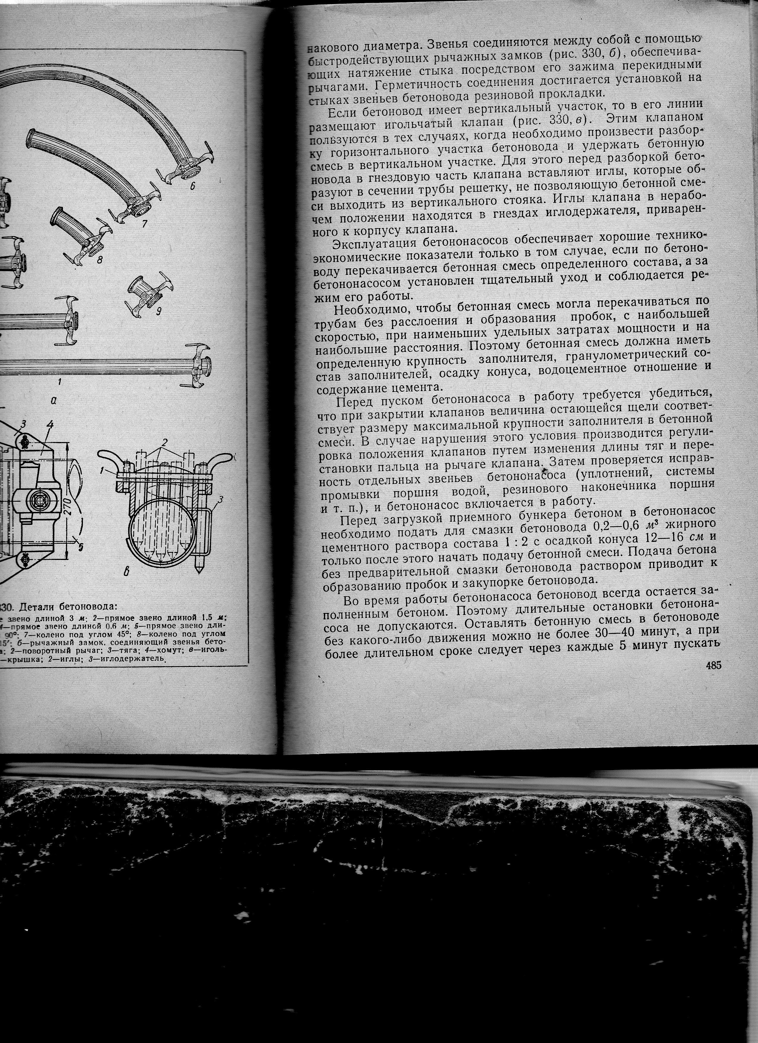
Детали бетоновода:
а
– комплект звеньев; 1
– прямое звено длиной 3м;
2
– прямое звено длиной 1,5м;
3
— прямое звено длиной 0,9м;
4
–
прямое звено длиной 0,6м;
5
– прямое звено длиной 0,3м;
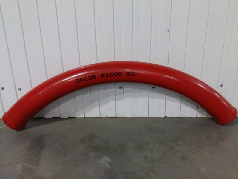
6
– колено под углом 90°; 7
– колено под углом 45°; 8
– колено под углом22°30′; 9
– колено под углом 11°15′;
б
–
рычажный замок, соединяющий звенья
бетоновода; 1
и 5
– звенья бетоновода; 2
— поворотный рычаг; 3
– тяга; 4
– хомут;
в
– игольчатый клапан; 1
– крышка; 2
– иглы; 3
– иглодержатель.


Пневматические
бетононагнетатели.
Предназначены
для перемещения порций бетона по трубам
при помощи сжатого воздуха.

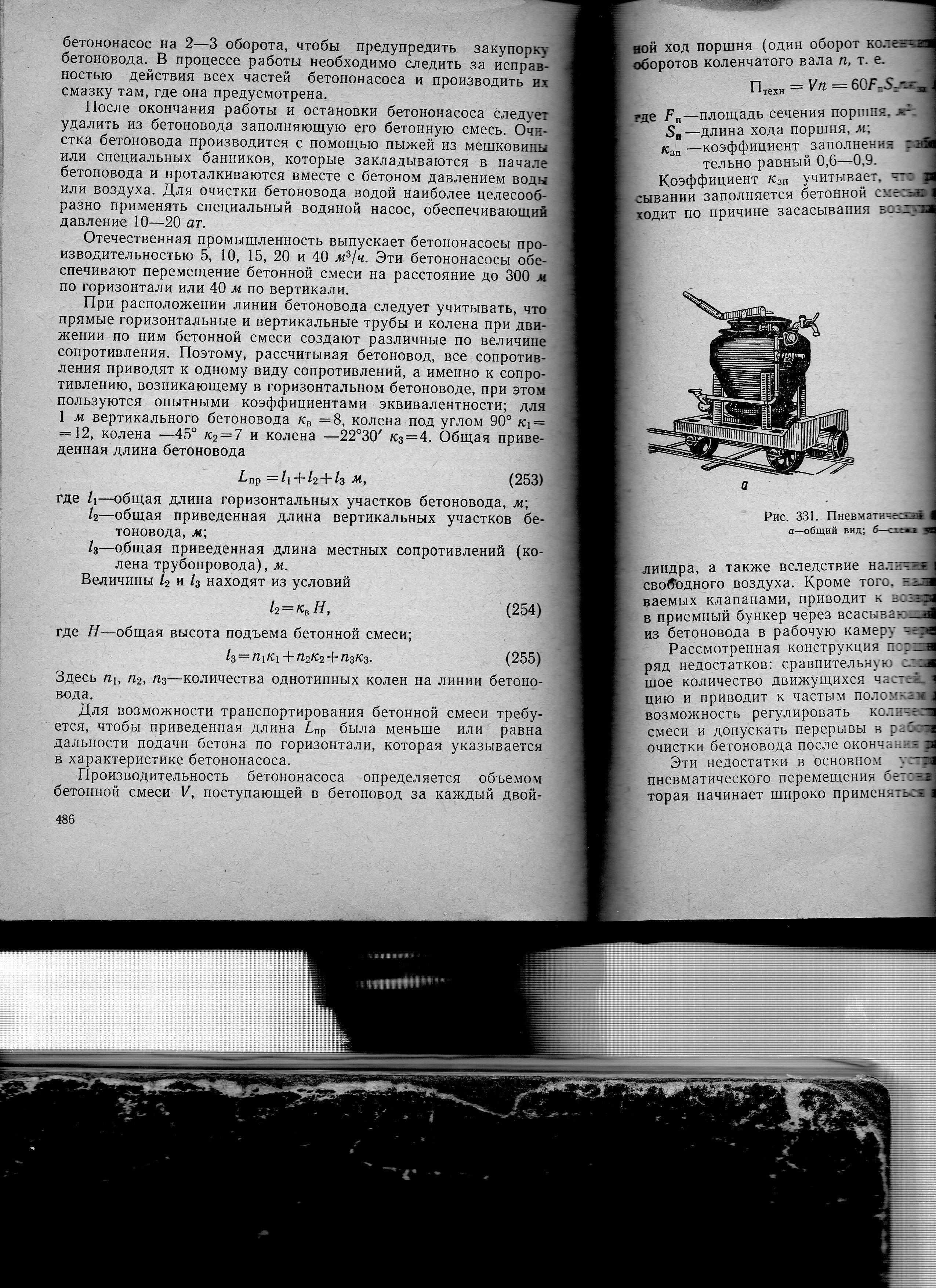
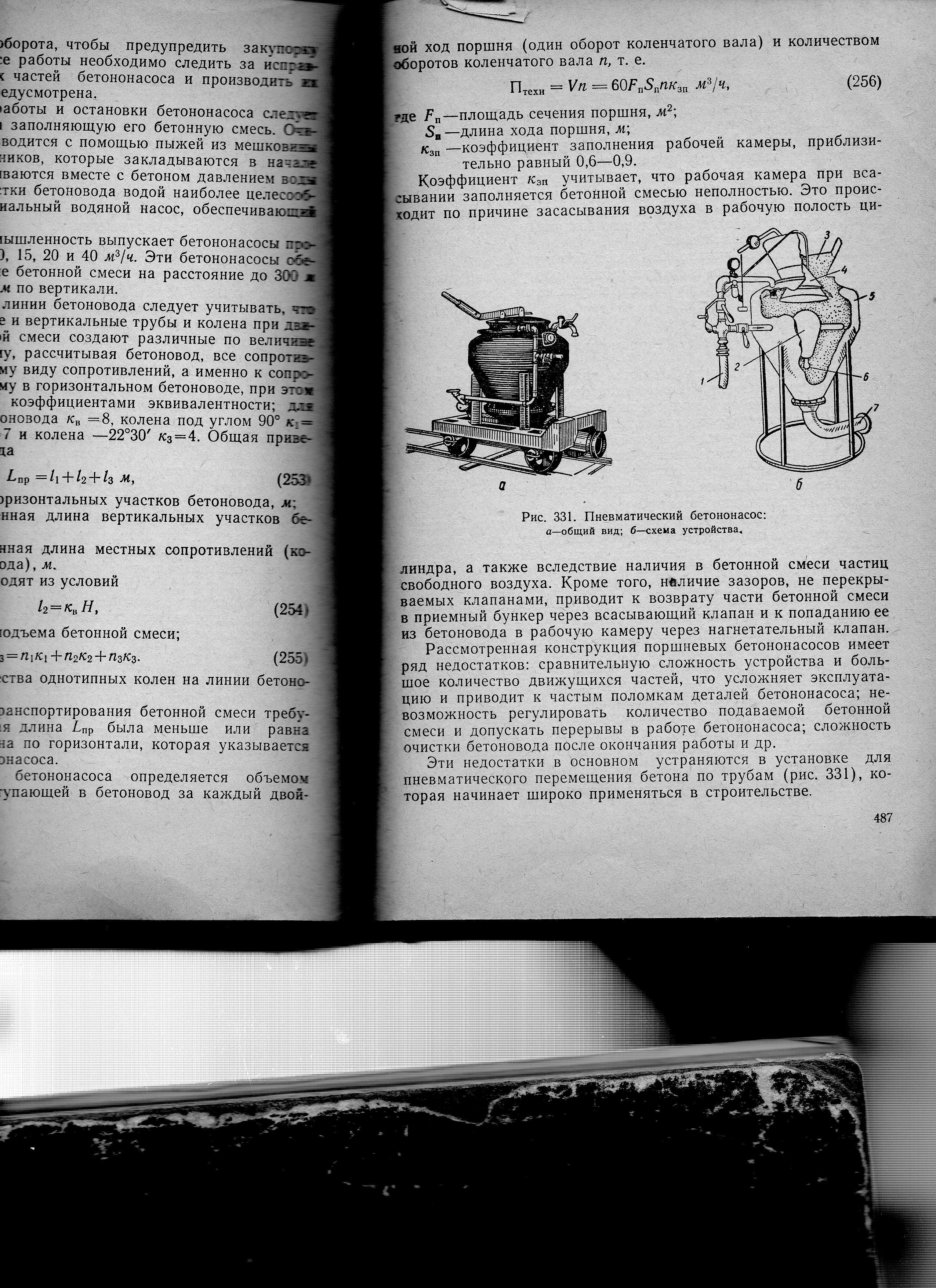
Рис.6.
Пневматический бетононасос:
а
—
общий вид; б
— схема устройства; 1
— трубопровод; 2
— направляющий конус;
3
— воронка; 4
— конусный затвор; 5
— резервуар; 6
— сопла.
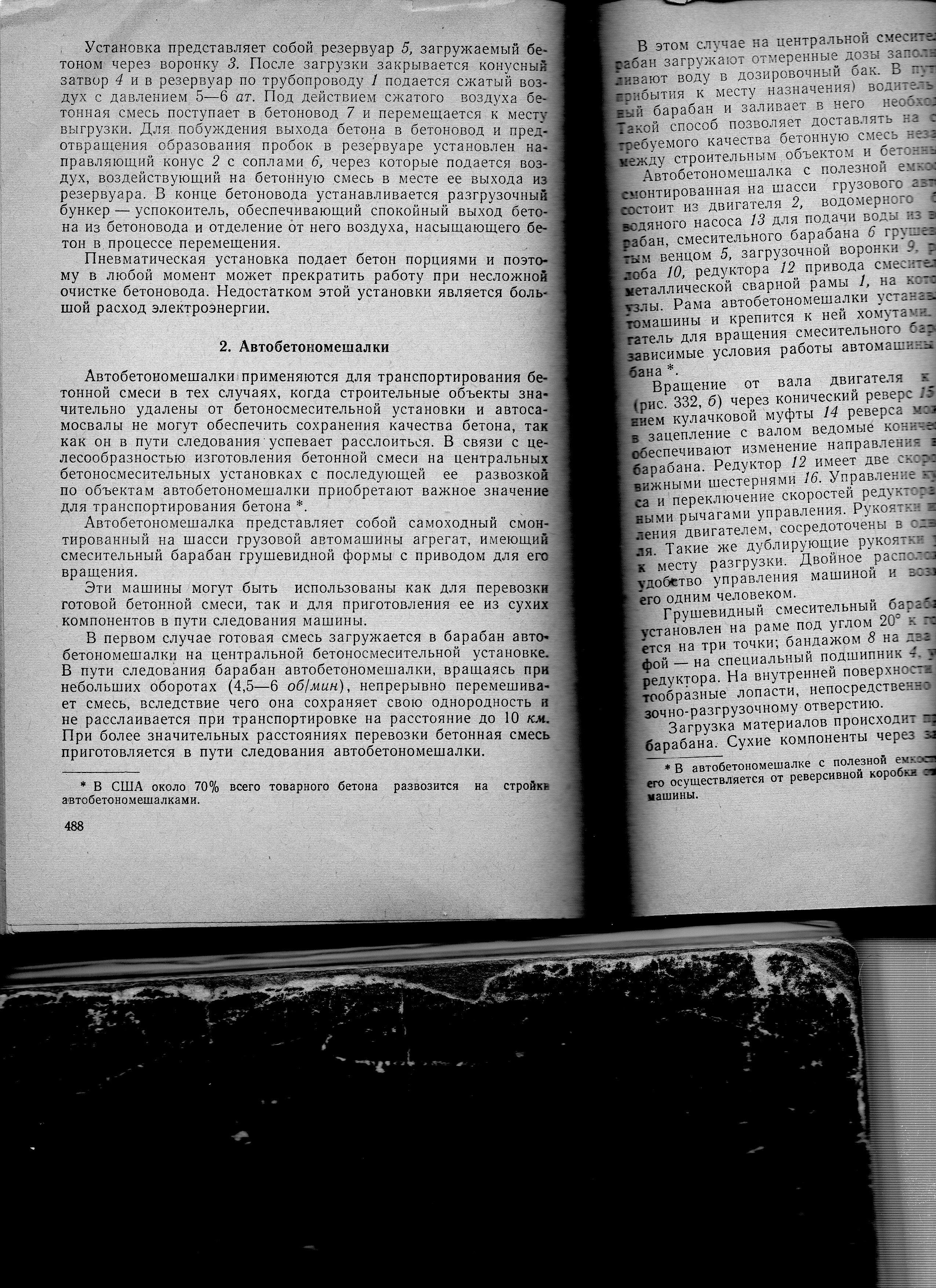

Дальность
подачи находится в пределах 150м.
Бетононасос
с гидравлическим приводом.
Частично
устраняет недостатки механического
привода. Они состоят из установленных
под расходным бункером-побудителем 2
двух рабочих цилиндров 4,
снабжённых двумя шиберными затворами-
вертикальным 7
и горизонтальным 6.
Движение поршням рабочих цилиндров и
шиберным затворам сообщается
маслоприводными цилиндрами 5
и 3.
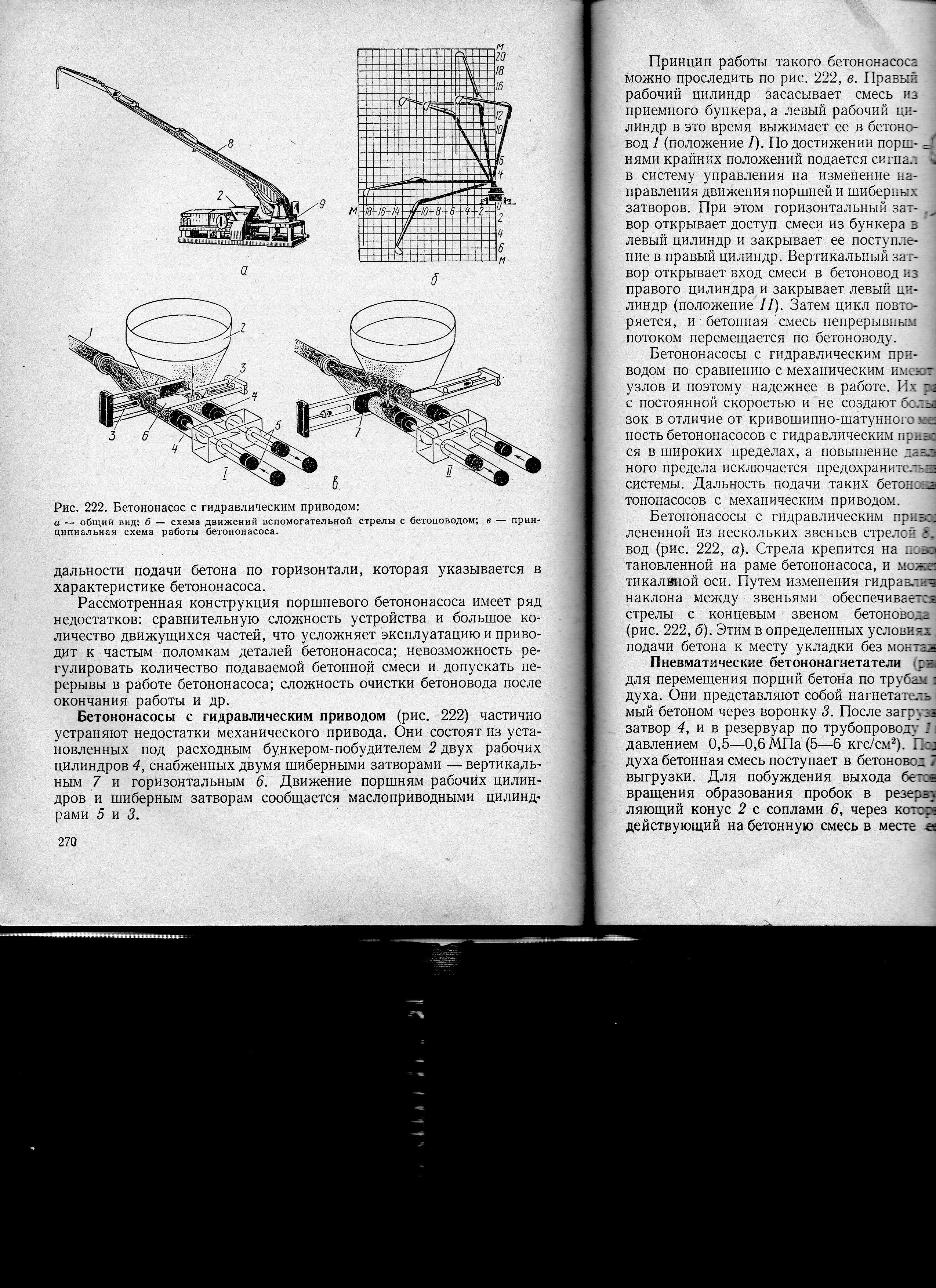
Рис.7.
Бетононасос с гидравлическим приводом:
а
– общий вид; б
– схема движений вспомогательной стрелы
с бетоноводом; в
– принципиальная схема работы
бетононасоса; 1
— ; 2
– бункер-побудитель; 3
и
5
–маслоприводные цилиндры; 4
– два расходных цилиндра;; 6
– горизонтальный шиберный затвор; 7
– вертикальный шиберный затвор.
Принцип
работы такого бетононасоса можно
проследить на рис.в.
Правый рабочий цилиндр засасывает смесь
из приёмного бункера, а левый рабочий
цилиндр в это время выжимает её в
бетоновод 1
(положение І).
По достижении поршнями крайних положений
подаётся сигнал в систему управления
на изменение направления движения
поршней и шиберных затворов. При этом
горизонтальный затвор открывает доступ
смеси из бункера в левый цилиндр и
закрывает её поступление в правый
цилиндр. Вертикальный затвор открывает
вход смеси в бетоновод из правого
цилиндра и закрывает левый цилиндр
(положение ІІ).
Затем
цикл повторяется, и бетонная смесь
непрерывным потоком перемещается по
бетоноводу.
Бетононасосы
с гидравлическим приводом по сравнению
с механическим имеют меньше конструктивных
узлов и поэтому надёжнее в работе. Их
рабочие поршни движутся с постоянной
скоростью и не создают больших инерционных
нагрузок в отличие от кривошипно-шатунного
механизма. Производительность
бетононасосов с гидравлическим приводом
может регулироваться в широких пределах,
а повышение давления свыше установленного
предела исключается предохранительными
устройствами гидросистемы. Дальность
подачи таких бензонасосов больше, чем
у бетононасосов с механическим приводом.
Бетононасосы
с гидравлическим приводом комплектуются
сочленённой из нескольких звеньев
стрелой 8,
несущей на себе бетоновод. Стрела
крепится на поворотной платформе 9,
установленной на раме бетононасоса, и
может вращаться вокруг вертикальной
оси. Путём изменения гидравлическими
цилиндрами угла наклона между звеньями
обеспечивается перемещение головки
стрелы с концевым звеном бетоновода в
нужное положение (рис.б).
Этим в определённых условиях достигается
возможность подачи бетона к месту
укладки без монтажа бетоновода.
Конструктивно,
в зависимости от назначения, бетононасосы
подразделяются на три
основные категории:
1)
–
автобетононасос;
2)
—
стационарный прицепной бетононасос;
3)
—
автобетононасос со смесителем.
1)
— автобетононасос
– передвижное строительное оборудование,
установленное на базе грузового
автомобиля. Оборудование работает по
следующему принципу: посредством
распределительной стрелы бетонная
смесь подается из бетоносмесителя к
месту ее непосредственной укладки. При
необходимости стрелу наращивают
дополнительным бетоноводом. Тип шасси
грузового автомобиля возможен от двух-
до пятиосного, вылет распределительной
стрелы зависит от конструкции установки
и колеблется от 16,1
до 57
метров.
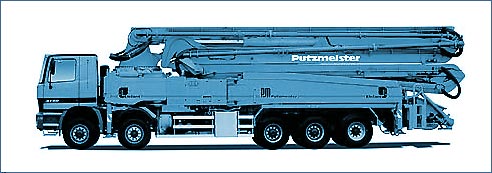
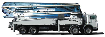
Рис.8.
Автобетононасос.
С
повышением требований к темпам и качеству
строительно-монтажных работ, инженерами
было разработано передвижное строительное
оборудование. В среде бетононасосной
техники были сконструированы
автобетононасосы – бетононасосы,
установленные на автомобильное шасси.
Основное
отличие автобетононасосов от стационарных
бетононасосов заключается в их
мобильности.
Автобетононасосы
предназначены для подачи свежеприготовленной
бетонной смеси в горизонтальном и
вертикальном направлениях распределительной
стрелой к месту укладки на строительных
объектах. Применение бетононасосов
значительно сокращает сроки возведения
зданий и сооружений, повышает качество
строительства, улучшает условия труда.
Автобетононасос,
также как и его стационарный собрат,
может работать в любых погодных условиях
с производительностью до 150
м3/час,
подавать бетон на высоту до 70
метров
и до 200
метров
по горизонтали.
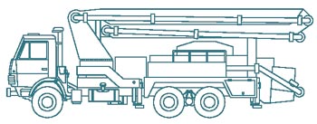
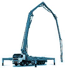
Рис.9.
Внешний вид автомобильных бетононасосов.
Автобетононасосы
оборудуются амортизационной системой,
которая минимизирует колебания вызванные
работой гидравлики. Современные
автомобильные бетононасосы оборудуются
электронной системой контроля качества
подаваемого бетона, а также регулируется
распределение нагрузки на стрелу, что
уменьшает амплитуду колебаний конструкции.
Большим
плюсом автобетононасоса, позволившим
интенсивно использовать этот вид техники
при сооружении объекта Укрытие над
разрушенным реактором Чернобыльской
АЭС,
является его мобильность. Это дало
возможность начать бетонирование стен
Саркофага дистанционно (на расстоянии)
и в короткий строк организовать весь
технологический процесс бетонирования.
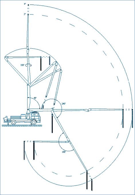
Рис.10.Схема
работы бетоновода автомобильного
бетононасоса
(трехсекционная стрела)
Применение
автобетононасосов при ликвидации аварии
на ЧАЭС позволило существенно сократить
сроки выполнения работ, сократить
потребности в рабочей силе и снизить
затраты.
Потребность
в дистанционном бетонировании при
сооружении Саркофага
Сооружение
объекта Укрытие, по первоначальному
проекту, предусматривало полную изоляцию
(захоронение) всех помещений, относящихся
к 4-му блоку ЧАЭС. Но после анализа
радиационных условий в местах проведения
работ (внутри помещений и на территории
ЧАЭС), а также обследования строительных
конструкций здания позволили упростить
конструкцию объекта Укрытие.
При
возведении стен объекта Укрытие был
предусмотрен следующий порядок
бетонирования. Армоблоки поставлялись
на АЭС в готовом виде. На участке с
наиболее благоприятной радиационной
обстановкой осуществлялась сборка их
в блок-опалубку.
Собранный
блок доставлялся к месту расположения
стенки и после монтажа бетоноводов и
установки бетононасосов производилась
укладка в него бетонной смеси.
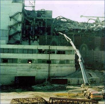
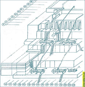
Рис.11.Схема
расположения бетононасосов при
строительстве
каскадной стены объекта Укрытие.
При
возведении некоторых наружных бетонных
стенок Укрытия армоблоки монтировались
на железнодорожных платформах. Количество
платформ определялось длинной стенки.
Для наиболее протяженной стенки
потребовалось 14
платформ,
рабочее место для сборки армоблоков
которой было определено в районе АБК-1,
т.е. на расстоянии 500-600
м
от места возведения стенки. При этом
для размещения платформ и доставки
опалубки к месту расположения стенки
использовался существовавших
железнодорожный путь.
Наибольшую
сложность представляли собой работы
по возведению каскадной стены высотой
5,75
м
в осях 43-51
вдоль ряда Ю.
Затем бетонировалось пространство
между этой стенкой и блоком Б
до верхней отметки стенки. На образованную
ступеньку максимально приблизившись
к развалу, устанавливалась опалубка:
армоблоки высотой 12
м,
для второй стенки за которую также
укладывался бетон, в результате
образовывалась вторая ступенька – ярус
каскадной стенки общей высотой 17,55
метров.
Аналогично первому и второму ярусам
возводились третий (общая высота 29,75
м
) и четвертый (общая высота 41.00м)
ярусы. Схема возведения каскадной стены
представлена на рисунке. При возведении
стенок внутри помещений армоблоки
устанавливались на место по отдельности.
В ряде случаев опалубка монтировалась
непосредственно на месте возведения
стенок.
Подача
бетона в армоблоки осуществлялась с
помощью передвижных и стационарных
бетононасосов, позволявших выносить
приемщики бетонной смеси на расстояние
150-200
метров
от мест установки армоблоков. К числу
использовавшихся бетононасосов относятся
Вортингтон (Worthington), Швинг (Schwing), Путцмейстер
(Putzmeister), БН-80-20.
Согласно
проекту защитной оболочки, разработанному
ВНИПИЭТ, при сооружении «Укрытия»
потребовалось уложить более 300
000 м3
бетона. При этом было смонтировано более
7
тысяч
тон
металлоконструкций. Работы были начаты
в конце мая 1986 года и окончены в ноябре
1986 года.
Устройство
автобетононасоса.
![]()
![]()
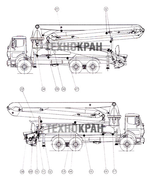
Рис.12.
Автобетононасос:
1
– захватный крюк; 2
– сигнальные индикаторы; 3
– смазочная система; 4
–
фиксация
конечной позиции телескопического
устройства спереди; 5
– блок управления левой опорой; 6
– водяной насос, сливной кран; 7
– фиксирующее устройство транспортного
положения сзади; 8
– выключатель звукового сигнала
(клаксона); 9
– панель управления мешалки; 10
–
панель блока управления; 11
– панель управления водяного насоса;
12
– блок регулирования; 13 – блок управления
бетононасосом; 14
– блок управления мачтой; 15
– фиксирующее устройство транспортного
положения сзади; 16
– блок управления правой опорой; 17
– фиксирующее устройство конечной
позиции телескопического устройства
спереди.
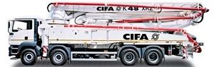
Рис.13.Автобетононасос
CIFA
K48 XRZ
Автобетононасос
CIFA
К48 XRZ
монтируется на 4-х осное шасси, оснащен
5-секционной раздаточной стрелой B5RZ
48/44
с диаметром бетоновода 125мм
с RZ-образной
кинематикой раскрытия, Х-образными
выдвижными аутригерами, что ускоряет
установку бетононасоса и упрощает его
помещение на узких площадках. Стрела
снабжена системой BFC
(быстросъемного крепления бетоновода),
а пропорциональное управление раскрытием
стрелы позволяет оператору независимо
управлять раскрытием секций.
Основные
характеристики:
• Компактная
и удобная конструкция, продуманная для
установки на четырехосное шасси.
• Задние
складывающиеся и передние складывающиеся
с телескопическим выдвижением опоры.
• Независимая
рама с защитой от деформации кручения.
• Выносные
опоры с гидравлическим приводом по
обеим сторонам машины.
• Пятисекционная
раздаточная стрела B5RZ
47/43
диаметром 125
мм
со смешанной Z-образной
и раскручивающейся кинематикой раскрытия.
• Пропорциональное
управление раскрытием стрелы позволяет
оператору независимо управлять раскрытием
секций.
• Регулятор
подачи бетона.
• Возможность
установки насосного узла серии HPG-IF
c закрытым гидравлическим контуром:
превосходная производительность,
высокое давление и поток бетона, простой
в обслуживании.
• Устройство
безопасности на открываемом смотровом
люке.
• Серия
насосов «F8»
высокой производительности: ровный,
непрерывный ток бетона в сочетании с
простотой обслуживания.
Таблица
1
Соседние файлы в предмете [НЕСОРТИРОВАННОЕ]
- #
- #
- #
- #
- #
- #
- #
- #
- #
- #
- #
В этой статье вы найдете информацию о первом запуске бетононасоса, а также рекомендации по эксплуатации и процессу завершения работы
В последнее время у покупателей появился интерес к списку рекомендаций и правил для первого запуска и эксплуатации бетононасоса, используемого для вертикальной и горизонтальной передачи бетонной смеси к месту ее укладки.
Потребность в покупке бетононасоса резко ощущается при необходимости прокачки больших объемов бетона за относительно малое количество времени на большое расстояние и высоту, например, если нужно доставить бетон на площадку высотки или передать по тоннелю. В такой ситуации используется бетононасос с бетонопроводом и распределительными стрелами.
Для того, чтобы верно произвести первый запуск бетононасоса нужно иметь представление о принципе его работы. Подробную информацию на эту тему можно найти в развернутой статье по ссылке
Операторы, работающие со бетононасосами должны быть компетентны в вопросах безопасности при использовании такого оборудования, так как помимо риска поломки техники, существуют реальные угрозы для жизни.
Зачастую в комплекте с бетононасосом идет инструкция по эксплуатации. Однако бывают ситуации, когда по какой-либо причине руководство пользователяотсутствует, а Вам необходимо запускать в работу бетононасос. Исходя из вышеперечисленных фактов, мы бы хотели дать список рекомендаций для работы с бетононасосом.
При работе с любой новой техникой в первую очередь нужно провести осмотр и проверить основные узлы.
При осмотре силового агрегата оператору нужно проверить:
- уровень масла в двигателе и гидравлической системе;
- уровень тосола в системе охлаждения;
- фильтра;
- качество и уровень зарядки аккумуляторной батареи.
При необходимости произвести замену неисправных компонентов. Если на бетононасосе не установлена центральная автоматическая или полуавтоматическая система смазки, то нужно произвести смазку основных трущихся узлов (пальцев, шарниров, шкворней) посредством пистолета для шприцевания. После полной проверки работоспособности бетононасос можно завести.
На следующем этапе работы мы выставляем бетононасос в непосредственном месте заливки, распираем опорными “лапами” и фиксируем так, чтобы он устойчиво стоял в горизонтальном положении. Если опора, грунт или та поверхность, на которой стоит бетононасос, является неустойчивой, либо непрочной, то необходимо подставить под колеса и под опорные “ноги” специальные деревянные подпорки, чтобы снизить давление бетононасоса на поверхность.
Выставлять бетононасос необходимо таким образом, чтобы для оператора был обеспечен комфортный доступ к бетоносмесителю, который подвозит бетон. Бетононасос обязательно должен находиться на расстоянии не менее 8 метров от места крепления бетоновода к стене. Этот горизонтальный “коридор” монтируется для того, чтобы бетон не выдавливало обратно в приемный бункер.
Теперь можно приступать к монтажу бетонопровода. Собирается бетонопровод из 2-4 метровых бетоноводов и фиксируется друг с другом посредством металлических хомутов с резиновыми уплотнительными кольцами. Для того чтобы при работе бетононасоса снять вибрационные движения с бетоновода, необходимо монтировать гибкий двухвальцовый кольцевик между бетононасосом и бетонопроводом.
Бетононасос в зависимости от марки, мощности и модели будет иметь определенную дальность и высоту подачи. Например, у бетононасосов от фирмы Atabey производительность бетона от 25 до 100 кубов в час, высота подъема до 100 м, а при вертикальной заливке бетона дальность подачи достигает 240 м.
После перехода с горизонтального на вертикальный выход бетоновода обязательно необходимо установить разгонное колено (90☌), представляющее из себя уголок с плавным углом поворота. Когда все работы по монтировке бетоновода к месту подачи бетона произведены, можно приступать к заливке.
Оператор должен знать весь функционал бетононасоса и работать синхронно вместе с водителем миксера (АБС), так как скорость подачи должна соответствовать скорости выгрузки бетона в бункер.
Перед стартом очень важно обратить внимание на несколько параметров. Первое это густота бетонной смеси. На строительную площадку иногда привозят густой бетон. Это может происходить по разным причинам: бетоносмеситель, может застрять в пробке, и бетон “сядет”; бетон могут не до конца размешать; плечо доставки может быть достаточно большим. Севший бетон или более плотный бетон способствовует закупориванию бетонопровода, в следствии чего достаточно опасным финалом будет его разрыв и выброс бетона.
Обычно закупоривание происходит по нескольким причинам:
- отсутствие смазки по бетонопроводу во время первого старта;
- неправильная укладка бетоновода;
- густая бетонная смесь;
- расслоение бетонной смеси.
Для запусков стационарных, мобильных и автобетононасосов используется специальная пусковая смесь. В целях безопасности и экономии времени при каждом новом запуске после прочистки бетононасоса нужно использовать пусковую смесь для первого старта.
Пусковая смесь — это специальный сухой порошок для смазки бетонопровода. Перед применением пусковую смесь разводят разводят в воде.
При первом запуске вместо пусковой смеси зачастую используется так называемое “молочко” для смазки бетонопровода, предотвращающее от заворачивания и закупоривания бетонной смеси. Если объем этого “молочка” слишком большой, либо в нем малое количество цемента, то оно начинает вымывать из бетонного раствора песок с цементом, таким образом происходит расслоение смеси: песок, цемент и “молочко” остаются сверху, а щебень оседает, и вследствие чего, на ближайшем конце образуется пробка.
“Молочко” — это заменитель пусковой смеси, состоящий из цемента и воды в примерной пропорции на 200 л воды 4 мешка цемента.
При горизонтальной подаче бетона, перед пусковой смесью, рекомендуется запускать хорошо смоченный водой спандж (промывочный шар), чтобы равномерно распределить “молочко” по бетоноводу.
После вышеперечисленных мер можно приступать к прогону бетона по бетоноводу и начинать заливку. Если мы говорим о вертикальной заливке бетона, то не рекомендуется при первом старте и в первые минуты прогона бетона использовать максимальные обороты. Если на конце трубы уже осуществляется раздача бетона, то потихоньку можно увеличивать обороты двигателя, а соответственно и скорость подачи.
Оператору следует следить за давлением в системе гидравлики бетононасоса. Как только вы видите, что давление в бетононасосе значительно превышает положенное, рекомендуется не дожидаться разрыва трубы, а сразу же начинать искать место в котором произошло закупоривание с помощью простукивания бетоновода, так как разрывы бетононасоса могут повлечь за собой трагические последствия.
Оператор в процессе перекачки держит связь с бетонщиками, корректирующими работу бетононасоса по радиосвязи. На многих бетононасосах может устанавливаться пульт радиоконтроля: оператор сам регулирует работу бетононасоса на расстоянии.

Бетононасос в рабочем состоянии имеет несколько режимов:
- режим прокачки бетона;
- режим ожидания;
- режим откачки бетона;
Если бетон используется без присадок, то не рекомендуется держать смесь в бетонопроводе в режиме ожидания более 25 минут, в противном случае бетоновод придется прочищать, так как бетон начнет “садиться”.
По окончании работы необходимо произвести замывку бетоновода и бетононасоса. Начинать стоит с максимальной откачки бетона из бетоновода. При этом уровень бетона должен находиться на границе с верхней кромкой цилиндра поршня. После этого оператор включает бетононасос в режим откачки: весь бетон, который есть в бетонопроводе, загоняется обратно в приемный бункер. Бывает такое, что не хватает приемного бункера для всего бетона. Чтобы не сорить на строительной площадке, под приемный бункер бетононасоса ставится небольшая ванна для слива остатков бетона.
После слива бетона следует взять специальные спанджи (промывочные шары), напитать их водой, вставить один спандж в конец бетонопровода и протолкнуть. Затем залить ведро воды и сверху вставить еще один спандж, и включить бетононасос на откачку. Это поможет отмыть бетонопровод от остатков бетона. Путем простукивания по трубе оператор может понять в каком месте спандж уже прошел. После того как спандж дошел до шароуловителя, нужно открыть хомуты и достать оттуда спанджи. Бетон, оставшийся в колене, мы замываем с помощью насосов с водой.
Оператор завершает смену тем, что вновь смазывает все трущиеся узлы высокотемпературной смазкой. Рекомендуется хранить бетононасос в закрытом помещении, чтобы не подвергать открытые участки металла коррозии.
Материал основан на экспертном мнении Корневого Ильи Викторовича, инженера-технолога, работающего с разными моделями бетононасосов.
| Найти: | |
| Где: | |
| Тип документа: | |
| Отображать: | |
| Упорядочить: |
Скачать Руководство по укладке бетонных смесей бетононасосными установками
Дата актуализации: 01.01.2021


Руководство по укладке бетонных смесей бетононасосными установками
| Статус: | Действует |
| Название рус.: | Руководство по укладке бетонных смесей бетононасосными установками |
| Дата добавления в базу: | 01.09.2013 |
| Дата актуализации: | 01.01.2021 |
| Дата введения: | 23.05.1978 |
| Область применения: | В руководстве содержатся рекомендации по технологии и организации укладки бетонных смесей с применением бетононасосных установок и их эксплуатации. Приведены основные требования к бетонным смесям и их составляющим, особенности транспортирования по трубам смесей в зимних условиях и на пористых заполнителях, методика определения гидравлических сопротивлений в трубопроводах, рекомендации по выбору оптимальных комплектов оборудования и специальным методам производства бетонных работ с применением бетононасосов. |
| Оглавление: | Предисловие 1 Общие положения 2 Оборудование для транспортирования бетонных смесей по трубам 3 Требования к бетонным смесям и их составляющим 4 Гидравлические сопротивления в трубопроводе и их влияние на производительность бетононасосов 5 Особенности транспортирования по трубам бетонных смесей на пористых заполнителях 6 Организация и производство работ при укладке бетонных смесей 7 Эксплуатация бетононасосных установок 8 Особенности применения бетононасосов в зимних условиях Приложения: 1 Устройство и принцип работы бетононасоса СБ-95А 2 Устройство бетоновода к бетононасосу СБ-95А 3 Техническая характеристика бетононасосов советского и зарубежного производства, применяемых в отечественном строительстве 4 Техническая характеристика и общие виды опытных образцов распределительных стрел 5 Определение удобоперекачиваемости бетонной смеси 6 Устройство и принцип работы перегрузочного бункера 7 Графики для определения показателей, влияющих на производительность бетононасосов и стоимость их эксплуатации 8 Принципиальные схемы и общие виды по применению бетононасосов 9 Определение продолжительности промежутка времени для отбора проб бетонной смеси на выходе из бетоновода 10 Определение экономической эффективности применения автобетононасосов 11 Определение температуры бетонной смеси в трубопроводах |
| Разработан: | ЦНИИОМТП |
| Утверждён: | 23.05.1978 ЦНИИОМТП (TsNIIOMTP ) |
| Издан: | Стройиздат (1978 г. ) |
| Расположен в: | Техническая документация Экология СТРОИТЕЛЬНЫЕ МАТЕРИАЛЫ И СТРОИТЕЛЬСТВО Строительное оборудование Строительство Справочные документы Директивные письма, положения, рекомендации и др. |
| Нормативные ссылки: |
|
 ГОСТ 8269-87 «Щебень из природного камня, гравий и щебень из гравия для строительных работ. Методы испытаний»


-
Bookmarks
Quick Links
Original operating instructions
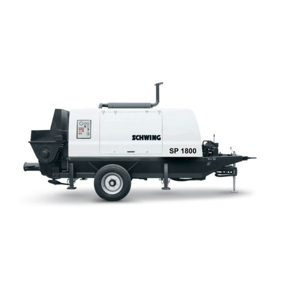
Stationary concrete pump
SP 1800
SP 2800
CAT
Related Manuals for Schwing SP 1800

Summary of Contents for Schwing SP 1800
-
Page 1
Original operating instructions Stationary concrete pump SP 1800 SP 2800… -
Page 2
Specify the machine type and the machine number stamped on the type plate of your machine when placing an order. Pass on these operating instructions when leaving the machine to someone else. Imprint: Editor: Schwing GmbH Department: TDS 1 Address: Heerstr. 9-27… -
Page 3
2.6 Technical data for SP 1800 / 2800 CAT ……. . -
Page 4
3.4 EMERGENCY-STOP system for SP 1800 / 2800 ……. 77… -
Page 5
1 Contents 3.5 Readying the machine for operation SP 1800/2800 ……81 3.5.1 Diesel engine …………84 3.5.2… -
Page 6
3.13 Working operation — Air system SP 1800 / 2800 …… -
Page 7
3.20.3 Semi-hydraulic outrigger SP 1800 …….. -
Page 8
4.5 Explanation of the maintenance schedule — Stationary concrete pump ..243 4.6 Maintenance plan for stationary concrete pump SP 1800/2800 ….245 4.6.1… -
Page 9
1 Contents 4.6.2 Concrete pump (pump kit) ……….246 4.6.3 Special equipment . -
Page 10
1 Contents 4.12.5 Checking the cutting ring ……….275 4.12.6 Rotating the cutting ring . -
Page 11
4.18.3 Changing the fuses in SCHWING components ……. . 335… -
Page 12
1 Contents 4.19.7 Notification of damage for safety components ……. . . 347 4.20 Repair welding . -
Page 13
2 Introduction This chapter contains the most important informa- tion about your machine, including: • Layout, • Conventions and • Handling Of these operating instructions. Trennblatt-Einleitung-EN.fm… -
Page 14
2 Introduction Trennblatt-Einleitung-EN.fm — 01.00.01… -
Page 15
In addition to the operating instructions, the general relevant legal and other rules on accident prevention of the country of operation should be observed. SCHWING GmbH is not liable for damages caused by a failure to observe these provisions and/or these operating instructions or by improper use of the machine! -
Page 16
The same also applies for the manufacturer of integrated motors used in our sta- tionary concrete pumps. Other special pieces of equipment on your SCHWING machine may also have their own operating instructions. Please observe these documents, in addition to the SCHWING operating instruc- tions, in order to service and maintain these components properly. -
Page 17
If you still have any questions or doubts after reading the operating instructions, please do not hesitate to contact the customer service department at Schwing GmbH. If necessary, you can also organise individual training seminars. -
Page 18
2.2 Structure of the operating instructions 2.2.2 Contents of the individual chapters in these operating instructions Introduction This chapter is intended to familiarise you with your machine. It contains, for example, the technical specifications, a short description and an overview of the machine. Operation In this chapter, you will find descriptions of all machine operating procedures, from commissioning to working operation and cleaning to decommissioning. -
Page 19
2.2 Structure of the operating instructions 2.2.3 Page layout of the operating instructions Header A dynamic column title is contained in the header on the outer edge of the page. The column title shows the corresponding sub-chapter currently being read, along with the chapter number and title. -
Page 20
2.2 Structure of the operating instructions 2.2.4 Structure of safety instructions In these operating instructions, safety instructions are placed in front of certain sec- tions to warn readers of dangers that could cause potential personal injury or ma- terial danger. The measures described to avert these dangers must be adhered to. -
Page 21
2.2 Structure of the operating instructions 2.2.6 Warning of material damage The following safety instructions describe the meaning of the signal word for mate- rial damage. ACHTUNG! Attention! Material damage! Damage to your own machine or other objects. Describes how the material damage can be avoided. 2.2.7 Additional information The following symbol indicates useful tips and recommendations, as well as infor-… -
Page 22
2.2 Structure of the operating instructions Aufbau-BA-EN.fm — 01.05.01… -
Page 23
2.3.1 Declaration of conformity SCHWING declares that the machine placed on the market in the European Eco- nomic Area complies with the relevant EC directives. We confirm this by issuing a declaration of conformity and affixing a CE mark to the machine. -
Page 24
Complete list of the applied national standards and technical specifications, see »Ref- erences in DIN EN 12001 conveying, spraying and placing machines for concrete and mortar — Safety requirements«, as well as the SCHWING factory standard. Noise emission Installed effective output… -
Page 25
Complete list of the applied national standards and technical specifications, see »Ref- erences in DIN EN 12001 conveying, spraying and placing machines for concrete and mortar — Safety requirements«, as well as the SCHWING factory standard. Noise emission P hydraulic = kW (hydraulic drive) -
Page 26
CE marking and declaration of conformity only apply to design and scope of deliv- ery of the machine delivered ex works. Making changes to the machine without the approval of SCHWING, in addition to using accessories without the approval of SCHWING, shall cause both to lose their validity. -
Page 27
• Improper operation by machine operators without adequate training or instruction • Using concrete pipelines that are not approved by SCHWING • Not performing the boom inspections and corresponding repairs on time Any discrepancies can affect the service life accordingly. The information specified with regard to the theoretical life does not constitute any commitment or guarantee, nor does it represent any other assurance as to a machine’s quality and durability. -
Page 28
In the event of damages of any kind, the entire machine must be inspected. Contact SCHWING in the event of operations outside of the indicated reference values The following applies to all SCHWING machines: Fresh concrete +15 °C… -
Page 29
2.5 Labelling SCHWING machines Labelling SCHWING machines The most common abbreviations and their meanings are listed and explained here. 2.5.1 Stationary concrete pumps SP 1800 BR02 Stationary concrete Pump 1800 technical parameters (minimum value) Series SP 3800 BR02 Stationary concrete Pump… -
Page 30
2.5 Labelling SCHWING machines Maschinenkennzeichnung-SP-EN.fm — 01.04.00… -
Page 31
2.6 Technical data for SP 1800 / 2800 CAT Technical data for SP 1800 / 2800 CAT Information Power ratings are theoretical max. values! WARNUNG! Warning! The specified concrete pressures require suitable pumping line material! (see “Operating the pumping line” on page 107) -
Page 32
2.6 Technical data for SP 1800 / 2800 CAT Technische Daten/Technical Data TBS, Juni 2017 SP1800 Stage IIIA / Tier3 Pumpenbatterie P1620 ‐120/80 Pump kit Motorhersteller und Typ Deutz TCD2013 L04 Engine Abgasstufe Diesel Stage IIIA/Tier3 Emission standard Motorleistung 126kW/169hp Engine power max. Motordrehzahl ‐1 2300min max. engine speed Tankinhalt Diesel 250ltr Fuel tank capacity Tankinhalt Hydrauliköl 400ltr Hydraulic tank capacity max. Betondruck stangenseitig/kolbenseitig 60bar/108bar max. concrete pressure rod side/piston side 870psi/1566psi max. Fördervolumen stangenseitig/kolbenseitig 84m³/h / 48m³/h… -
Page 33
2.6 Technical data for SP 1800 / 2800 CAT Technische Daten/Technical Data TBS, März 2017 SP1800 Stage IIIB / Tier4i Pumpenbatterie P1620 ‐120/80 Pump kit Motorhersteller und Typ Caterpillar C4.4 Engine Abgasstufe Diesel Stage IIIB/Tier4i Emission standard Motorleistung 129kW/173hp Engine power max. Motordrehzahl ‐1 2200min max. engine speed Tankinhalt Diesel 250ltr Fuel tank capacity Tankinhalt Hydrauliköl 400ltr Hydraulic tank capacity max. Betondruck stangenseitig/kolbenseitig 60bar/108bar max. concrete pressure rod side/piston side 870psi/1566psi max. Fördervolumen stangenseitig/kolbenseitig 80m³/h / 46m³/h… -
Page 34
2.6 Technical data for SP 1800 / 2800 CAT Technische Daten/Technical Data TBS, Januar 2018 SP1800 Stage IV / Tier4f Pumpenbatterie P1620 ‐120/80 Pump kit Motorhersteller und Typ Caterpillar C4.4 Engine Abgasstufe Diesel Stage IV/Tier4f Emission standard Motorleistung 129kW/173hp Engine power max. Motordrehzahl ‐1 2200min max. engine speed Tankinhalt Diesel 250ltr Fuel tank capacity Tankinhalt Hydrauliköl 400ltr Hydraulic tank capacity max. Betondruck stangenseitig/kolbenseitig 60bar/108bar max. concrete pressure rod side/piston side 870psi/1566psi max. Fördervolumen stangenseitig/kolbenseitig 80m³/h / 46m³/h… -
Page 35
2.6 Technical data for SP 1800 / 2800 CAT Technische Daten/Technical Data TBS, Juni 2017 SP2800 Stage IIIA / Tier3 Pumpenbatterie P1620 ‐120/80 Pump kit Motorhersteller und Typ Deutz TCD2012 L06 Engine Abgasstufe Diesel Stage IIIA/Tier3 Emission standard Motorleistung 147kW/197hp Engine power max. Motordrehzahl ‐1 2300min max. engine speed Tankinhalt Diesel 250ltr Fuel tank capacity Tankinhalt Hydrauliköl 400ltr Hydraulic tank capacity max. Betondruck stangenseitig/kolbenseitig 60bar/108bar max. concrete pressure rod side/piston side 870psi/1566psi max. Fördervolumen stangenseitig/kolbenseitig 112m³/h / 64m³/h… -
Page 36
2.6 Technical data for SP 1800 / 2800 CAT Technische Daten/Technical Data TBS, März 2017 SP2800 Stage IIIB / Tier4i Pumpenbatterie P1620 ‐120/80 Pump kit Motorhersteller und Typ Caterpillar C7.1 Engine Abgasstufe Diesel Stage3B/Tier4i Emission standard Motorleistung 151kW/203hp Engine power max. Motordrehzahl ‐1 2200min max. engine speed Tankinhalt Diesel 250ltr Fuel tank capacity Tankinhalt Hydrauliköl 400ltr Hydraulic tank capacity max. Betondruck stangenseitig/kolbenseitig 60bar/108bar max. concrete pressure rod side/piston side 870psi/1566psi max. Fördervolumen stangenseitig/kolbenseitig 112m³/h / 64m³/h… -
Page 37
2.6 Technical data for SP 1800 / 2800 CAT Technische Daten/Technical Data TBS, Juni 2017 SP2800 Stage IV / Tier4f Pumpenbatterie P1620 ‐120/80 Pump kit Motorhersteller und Typ Caterpillar C7.1 Engine Abgasstufe Diesel Stage IV /Tier4f Emission standard Motorleistung 168kW/225hp Engine power max. Motordrehzahl ‐1 2200min max. engine speed Tankinhalt Diesel 250ltr Fuel tank capacity Tankinhalt Hydrauliköl 400ltr Hydraulic tank capacity max. Betondruck stangenseitig/kolbenseitig 60bar/108bar max. concrete pressure rod side/piston side 870psi/1566psi max. Fördervolumen stangenseitig/kolbenseitig 112m³/h / 64m³/h… -
Page 38
2.6 Technical data for SP 1800 / 2800 CAT Techn-Daten-SP-1800-2800-CAT-EN.fm — 01.00.00… -
Page 39
2.7 Assembly groups and designations for your machine SP 1800 / 2800 Assembly groups and designations for your machine SP 1800 / 2800 This chapter contains an overview of the main assembly groups for your machine and their respective positions. -
Page 40
2.7 Assembly groups and designations for your machine SP 1800 / 2800 2.7.5 Concrete pump The concrete pump is a two-cylinder piston pump with a rock valve. The most important assembly groups (Fig. 3 Concrete pump) include: Rock valve Pumping cylinder and piston Water box Hydraulic drive cylinder 2.7.6… -
Page 41
2.7 Assembly groups and designations for your machine SP 1800 / 2800 Fig. 3 Concrete pump Caption (Fig. 3 Concrete pump) Pos. Description Rock valve Pumping cylinder and piston Water box Hydraulic differential cylinders (drive cylinders) Baugruppen-SP-1800-2800-EN.fm — 01.01.00… -
Page 42
2.7 Assembly groups and designations for your machine SP 1800 / 2800 2.7.7 On the left in the direction of travel Fig. 4: Side view on the left in the direction of travel Caption (Fig. 4: Side view on the left in the direction of travel) Pos. -
Page 43
2.7 Assembly groups and designations for your machine SP 1800 / 2800 2.7.8 On the right in the direction of travel Fig. 5 Side view on the right in the direction of travel Caption (Fig. 5 Side view on the right in the direction of travel) Pos. -
Page 44
2.7 Assembly groups and designations for your machine SP 1800 / 2800 2.7.9 Aerial view Fig. 6: Aerial view Caption (Fig. 6: Aerial view) Pos. Description Pos. Description EMERGENCY-STOP button Baugruppen-SP-1800-2800-EN.fm — 01.01.00… -
Page 45
Fig. 7 Noise level The indicated value represents an average value for the respective series, plus a safety margin. SCHWING guarantees that this value will not be exceeded by newly delivered, ex works machines. Information Regarding noise emissions, please observe the regionally applicable reductions in operating time! Geraeuschemission-SP-EN.fm — 01.11.01… -
Page 46
2.8 Noise information 2.8.2 The highest sound pressure level (L The sound pressure level is a measure of the sound emissions in the workplace. Machines equipped with a remote control unit as standard have no fixed workplace. In this case, the Machine Directive prescribes that the highest sound pressure level be measured at a distance of 1 m from the machine surface and 1.6 m across the ground, which must be indicated in the operating instructions. -
Page 47
95 dB(A) 123 dB(A) driving direction SP 1400 D 123 dB(A) 4 m from the front, SP 1800 D 92 dB(A) on the left in the 90 dB(A) 123 dB(A) driving direction SP 1800 E… -
Page 48
2.8 Noise information Fig. 9 Measuring point (L ) measured from the front pAmax Ground clearance: 1.6 m Operate the machine at maximum hydraulic Taking the measurement: power Information The measured sound pressure level (L ) is also influenced by the installed drive power and the drive motor used. -
Page 49
Pictographs without text Different warning and information signs in the national language are located on your SCHWING concrete pump, in addition to textless pictographs. An overview of all signs without text can be found below. Pictographs without text are situated on various control elements on the machine. -
Page 50
2.9 Pictographs without text 2.9.1 Pictographs Concrete pump Start-up damping Delivery rate Start-up damping on / off adjustment Pumping — 0 — Sucking 10144573 10187511 10144566 98362082 Agitator Concrete pump Isolation valve Isolation valve Pump operation (P) — 0 — Suck — 0 — Pump open close… -
Page 51
2.9 Pictographs without text Speed adjuster Water pump Compressor CE signs 10086507 10158389 10144568 10148919 Main switch battery Delivery note box — No tread surface on — off 98394724 98393988 Stowing box EASy display Underride protection device Up — 0 — Down 10191719 10200927 98361549… -
Page 52
2.9 Pictographs without text Lifting eye; 98363577* 10163380 Attention! Example values for: • Horizontal trailer load • Vertical trailer load 98381870* 98381419* * = For stationary concrete pumps only Textlose-Bildzeichen-EN.fm — 01.04.00… -
Page 53
2.10 Control, warning and steering elements SP 1800 / 2800 2.10 Control, warning and steering elements SP 1800 / 2800 This chapter clearly describes the positions of the control, warning and steering el- ements on your machine. 2.10.1 Concrete pump control The concrete pump control lets the operator control all functions of the concrete pump electronically. -
Page 54
2.10 Control, warning and steering elements SP 1800 / 2800 Fig. 11 Concrete pump control Caption (Fig. 11 Concrete pump control) Pos. Description Fuel level warning light Illuminated ON / OFF button for agitator suction operation Illuminated ON / OFF button for agitator pumping operation… -
Page 55
2.10 Control, warning and steering elements SP 1800 / 2800 Caption (Fig. 11 Concrete pump control) Pos. Description Illuminated button for concrete pump pumping operation EMERGENCY STOP Water pump Compressor Power outlet for remote control cable / dummy plug Hydraulic oil temperature indicator CAT control 2.10.2 Cable remote control… -
Page 56
2.10 Control, warning and steering elements SP 1800 / 2800 2.10.3 CAT control (IOPU control panel) Information Note that regeneration occurs automatically with the SP 1800 CAT TIER 4i and 2800 TIER 4f. Fig. 13 IOPU Tier 4i, Stage IIIB — CAT control panel Caption (Fig. -
Page 57
2.10 Control, warning and steering elements SP 1800 / 2800 Caption (Fig. 13) Pos. Description IOPU control station connector: Connects the IOPU control station to the motor wiring harness. «Left arrow» button: The operator can use this button to scroll through error lists in measurement display screens and through settings in the settings screen. -
Page 58
2.10 Control, warning and steering elements SP 1800 / 2800 2.10.4 TSC function The TSC function allows you to change and save the motor’s rotational speed on the control panel. The function is the equivalent of a cruise control in a passenger vehicle. -
Page 59
2.10 Control, warning and steering elements SP 1800 / 2800 2.10.5 “Regeneration” instructions Information Engine power failure! Observe the possible automatic regenerations of the diesel engine. The motor speed can be lowered automatically or the diesel engine will be switched off in pumping operation. -
Page 60
2.10 Control, warning and steering elements SP 1800 / 2800 13. If generation is not carried out, then the motor is automatically locked and shuts down. When restarting, the motor shuts down again after 30 seconds and can only be unlocked again by authorised service technicians. -
Page 61
2.10 Control, warning and steering elements SP 1800 / 2800 Fig. 15 The “Regeneration” key-operated switch Fig. 16 Caption (Fig. 16) Pos. Description Locking bar for grid assembly filling-in hopper Cleaning cover of the rock valve Lubrication point Locking bar for outrigger Hydraulic oil pressure gauge for concrete pump Kontroll-Warn-Steuerelemente-SP-1800-2800-EN.fm — 01.03.00… -
Page 62
2.10 Control, warning and steering elements SP 1800 / 2800 2.10.6 Hydraulic oil filter Fig. 17 Caption (Fig. 17) Pos. Description Hydraulic oil filter 2.10.7 Water separator A warning is issued when the water level in the fuel/water separator is too high. -
Page 63
2.10 Control, warning and steering elements SP 1800 / 2800 Fig. 18 Caption (Fig. 18) Pos. Description Breather screw on the water separator 2.10.8 Output regulation Fig. 19 Kontroll-Warn-Steuerelemente-SP-1800-2800-EN.fm — 01.03.00… -
Page 64
2.10 Control, warning and steering elements SP 1800 / 2800 Caption (Fig. 19) Pos. Description Output regulation of the concrete pump 2.10.9 Fuel filter Fig. 20 Caption (Fig. 20) Pos. Description Fine fuel filter Course fuel prefilter Fig. 21 Caption (Fig. 21) Pos. -
Page 65
2.10 Control, warning and steering elements SP 1800 / 2800 2.10.10 Main switch for starter batteries The main switch for the starter batteries (1) and the button for the forced switch-off (2) are located on the left in the direction of travel for the machines described in these operating instructions. -
Page 66
2.10 Control, warning and steering elements SP 1800 / 2800 2.10.11 Forced motor switch-off Interruption of the run-on function! The motor can be switched off immediately via a forced switch-off in case of an emergency. To do so, actuate the button (2) (Fig. 24). -
Page 67
3 Operation This chapter describes: • All of your machine’s operating modes • Safe and proper handing • Safe and economical operation Trennblatt_Kapitel-Betrieb-EN.fm… -
Page 68
3 Operation Trennblatt_Kapitel-Betrieb-EN.fm — 01.00.00… -
Page 69
3.1 Driving operation PLC Driving operation PLC Information Stationary concrete pumps may only be driven in open road traffic with the appro- priate approval. The equipment for the concrete pump with a chassis frame approved for road traffic may require an amendment to the operating instructions. This amendment is provided as a separate document, as needed. -
Page 70
3.1 Driving operation PLC Tyre size Air pressure (bar/psi) 275 / 70 R 22.5 7.0 / 102 445 / 45R 19.5 9.0 / 130 3.1.3 Transporting people and goods Stationary concrete pumps are work machines. They may not be used for the transport of people and goods. This also applies for the transport of concrete in the filling-in hopper of the concrete pump. -
Page 71
3.2 Installation site of the stationary concrete pump Installation site of the stationary concrete pump SCHWING recommends not driving onto the jobsite until you have been briefed by an “instructor” authorised by the site management. If stationary concrete pumps (SP) are used for up-pumping or down-pumping, a certain amount of “run-up track”… -
Page 72
During bad weather, the placing boom must be folded together into transport posi- tion. Information As of May 2012, SCHWING concrete pumps are equipped with a connection option for an earthing cable. Before connecting the earthing cable, the supporting surfaces must be bare metal! -
Page 73
The earthing cable and conductive metal rod are not included in the scope of deliv- ery of your SCHWING machine. A stainless steel screw M12 with nut is pre-installed for the earthing connection on one of the two vertical spars (1) (Fig. 27) on the rock valve support (screw inside, nut outside). -
Page 74
3.2 Installation site of the stationary concrete pump Aufstellungsort-SP-waehlen-EN.fm — 01.06.00… -
Page 75
3.3 Electrical connection (optional) Electrical connection (optional) GEFAHR! Danger! Only authorised personnel may connect, commission and disconnect electri- cally driven machines. Only authorised personnel may open the switch cabinet. The operator must initiate the correct connection of the machine. In Germany, a special feed point is required in accordance with VDE 0100 § 55 (e.g. -
Page 76
3.3 Electrical connection (optional) 3.3.1.2 Safeguarding and conductor cross-sections Electric motor Supply line max. 100m mm² Fuse (A) 4 x 16 4 x 25 4 x 35 4 x 50 4 x 70 4 x 95 4 x 120 4 x 185 4 x 240 3.3.2 Checking the rotational direction of the electric motors (control without phase… -
Page 77
3.3 Electrical connection (optional) Fig. 28 Proceed as follows to check the rotational direction: • Switch on the motor briefly • Check rotational direction by looking at the fan wheel • Switch the phases if rotating in the wrong direction •… -
Page 78
3.3 Electrical connection (optional) Elektrischer-Anschluss-EN.fm — 01.10.00… -
Page 79
3.4 EMERGENCY-STOP system for SP 1800 / 2800 EMERGENCY-STOP system for SP 1800 / 2800 Your machine’s EMERGENCY-STOP system is intended to allow you to shut off dangerous machine functions as quickly as possible when other protective meas- ures that have already been taken do not suffice. -
Page 80
3.4 EMERGENCY-STOP system for SP 1800 / 2800 Fig. 30 Remote control WARNUNG! Warning! The motor is not switched off! Such special equipment having locked control levers also continues to run. Switch off the motor or special equipment, if necessary, as described in the cor- responding chapters. -
Page 81
3.4 EMERGENCY-STOP system for SP 1800 / 2800 3.4.1 Restarting the machine after an EMERGENCY STOP Switch all locked selector switches and control levers to the centre or 0 position. Remedy the fault. Unlock the EMERGENCY-STOP button by turning it towards the arrow. -
Page 82
3.4 EMERGENCY-STOP system for SP 1800 / 2800 Not-Halt-System-SP-1800-2800-EN.fm — 01.02.00… -
Page 83
3.5 Readying the machine for operation SP 1800/2800 Readying the machine for operation SP 1800/2800 Check the hydraulic oil level in the reservoir. The hydraulic oil box is located on the left in the direction of travel. The oil level must be visible between “min” and “max”… -
Page 84
3.5 Readying the machine for operation SP 1800/2800 • Ensure that the screw joints of the hydraulic system are tight, and tighten them if necessary. • Fill the water box (1) (Fig. 32) to the top edge of the pumping pistons. If there is a danger of frost, only add water immediately before concreting. -
Page 85
3.5 Readying the machine for operation SP 1800/2800 Fig. 33 Pressure control for concrete pump The ball valve is used to block the concrete pump during repair work. • Check the grid assembly in the concrete filling hopper. Two locking bars (3) (Fig. 34) are used to secure the grid assembly. -
Page 86
3.5 Readying the machine for operation SP 1800/2800 GEFAHR! Danger! The machine may only be commissioned with closed covering caps and tightly closed grid assembly. Shutdowns triggered by the end limit switch are not EMERGENCY-OFF shut- downs. The agitator and concrete pump restart after closing the grid assembly. -
Page 87
3.5 Readying the machine for operation SP 1800/2800 The filling neck (1) (Fig. 36) for the fuel tank is located on top of the fuel tank. The fuel tank features a level indicator (2) (Fig. 36). • Top up diesel fuel, if necessary. Refer to the motor operating instructions for the fuel quality. -
Page 88
3.5 Readying the machine for operation SP 1800/2800 3.5.2 Fuel prefilter Any accumulated water must be drained daily from the settling vessel on the fuel prefilter (1) (Fig. 37) according to manufacturer’s instructions. Water collects in the lower part of the vessel. -
Page 89
3.5 Readying the machine for operation SP 1800/2800 Fig. 38 Fig. 39 Fig. 40 Fig. 41 Betriebsbereitschaft-herstellen-SP-1800-2800-EN.fm — 01.02.00… -
Page 90
3.5 Readying the machine for operation SP 1800/2800 Fig. 42 Fig. 43 Betriebsbereitschaft-herstellen-SP-1800-2800-EN.fm — 01.02.00… -
Page 91
3.5 Readying the machine for operation SP 1800/2800 3.5.4 Theoretical operating time Plan the operating times of the machine carefully before commencing work. Find out about the average fuel consumption using the consumption values and thus calculate the theoretical operating times, see motor operating instructions! -
Page 92
3.5 Readying the machine for operation SP 1800/2800 3.5.5 Example of an operating time calculation Theoretically, the following operating times apply for each full tank with an average fuel consumption of approx. 220 g per kW and hour: Fig. 44 To A) Max. -
Page 93
3.6 Drive circuit SP 1800 / 2800 Drive circuit SP 1800 / 2800 3.6.1 Starting the diesel engine VORSICHT! Caution! Unintentional start-up! Hydraulic oil pressure is built up automatically! After starting the drive motor, the hydraulic pumps immediately deliver oil. -
Page 94
3.6 Drive circuit SP 1800 / 2800 Fig. 45 Control panel with regeneration Fig. 46 Control panel with TSC Antriebsschaltung-SP-1800-2800-EN.fm — 01.06.00… -
Page 95
3.6 Drive circuit SP 1800 / 2800 Fig. 47 3.6.2 Switching off the diesel engine Allow the engine to idle for a few minutes to equalise the temperature. Only switch off the engine at full load in an absolute emergency. -
Page 96
3.6 Drive circuit SP 1800 / 2800 Fig. 48 Maintenance flaps on left in direction of travel 3.6.3 Forced switch-off of motor The motor can be switched off immediately via a forced switch-off in case of an emergency. Fig. 49 Button for forced motor switch-off … -
Page 97
3.6 Drive circuit SP 1800 / 2800 VORSICHT! Caution! Motor damage caused by forced switch-off! Only use the interruption of the run-on function (forced switch-off of motor) in case of emergency. Repeatedly forcing the motor to switch off at short intervals can cause severe motor damage. -
Page 98
3.6 Drive circuit SP 1800 / 2800 Antriebsschaltung-SP-1800-2800-EN.fm — 01.06.00… -
Page 99
3.7 Setting up the machine Setting up the machine The installation site must be set up so that the transport vehicles can reach the con- crete filling hopper without any problems and the machine is accessible for main- tenance and cleaning purposes. •… -
Page 100
3.7 Setting up the machine 3.7.1 Downtimes • Secure the machine against unintentional changes of position, even during short downtimes. Information Brake wedges are not included in your machine’s scope of delivery! Machines without a “chassis frame for road traffic” do not have brakes. If the machine remains at an installation site for an extended period of time, we rec- ommend removing the wheels (prior to lifting, loosen the wheel nuts). -
Page 101
Chain lengths that are too short lead to serious strain on the straight frame. When transporting the machine with chain slings, the individual chain lengths must be a minimum of 2.5 m! 3.7.3 Machine with chassis frame (SP 1800) • Drive the machine to the prepared installation site. •… -
Page 102
• Secure the machine using the wheel wedge (1) (wheel wedges are not included in the scope of delivery) (Fig. 54). • Uncouple the towing vehicle. Fig. 52 Support jack (SP 1800) Caption of (Fig. 52) Pos. Designation Socket pin… -
Page 103
3.7 Setting up the machine Fig. 53 Example illustration Fig. 54 3.7.4 Machine with chassis frame (SP 3800) • Drive the machine to the prepared installation site. • Lay a suitable support pad (e.g. item no.: 1095646) under the supporting dish of the crank support (Fig. -
Page 104
3.7 Setting up the machine Fig. 55 Support jack (SP 3800) Caption of (Fig. 55) Pos. Designation Socket pin Interior tube Crank Exterior tube Fig. 56 Example illustration Maschine-aufstellen-EN.fm — 01.03.00… -
Page 105
3.7 Setting up the machine Fig. 57 3.7.5 Mechanical outrigger • Lower the front of the machine using the crank (3) (Fig. 55) / (Fig. 52). • Lower the rear supports (2) (Fig. 53) / (Fig. 56) and secure with socket pins and split pins. -
Page 106
3.7 Setting up the machine 3.7.6 Semi-hydraulic outrigger (optional) For the semi-hydraulic outrigger, the oil flow from the agitator pump is directed into the control blocks of the outrigger. • Lower the front of the machine using the crank (3) (Fig. 52) / (Fig. 55). •… -
Page 107
These inspections should be documented in a suitable form. The operator should check the support equipment for damages and wear prior to each use. The connection and safety parts should be checked in particular for tight- ness and functionality. Fig. 58 Grease nipples (SP 1800) Maschine-aufstellen-EN.fm — 01.03.00… -
Page 108
3.7 Setting up the machine Fig. 59 Grease nipples (SP 3800) Maschine-aufstellen-EN.fm — 01.03.00… -
Page 109
3.8 Operating the pumping line Operating the pumping line 3.8.1 Observation during operation Prior to operation, make sure that the pumping line is in sound operating condition. Check the safety devices of the pumping line, see (Fig. 60). Fig. 60 VORSICHT! Caution! Injury caused by the cocking lever springing open! -
Page 110
We strongly recommend setting up the pumping line exclusively with appropriate SCHWING material. This is an important contribution to high operational safety and efficiency. SCHWING is not liable for any damages caused as a result of using inappropriate material! 3.8.2 Marking pumping pipes and elbows All SCHWING pumping pipes and elbows are marked as follows, example (Fig. -
Page 111
Fig. 63 Tapered tube marking as of approx. 2017 Fig. 64 Elbow marking as of approx. 2017 Caption for (Fig. 62) — (Fig. 64) Designation Meaning Charge Order no., customer no. Date Production week (MM/YY) Material SCHWING item no. Foerderleitung_Betrieb-EN.fm — 01.15.03… -
Page 112
Caption for (Fig. 62) — (Fig. 64) Designation Meaning Dimensions mm/degree Nominal size in mm (inner diameter) SUPER 1000 SCHWING quality label WTmm Total thickness (inside wall + outside wall) permissible operating pressure in bar WeightNET/pc. Net unit weight Outer diameter mm Tube, elbow and tapered tube weight per Weight-FWC/pc. -
Page 113
3.8 Operating the pumping line Fig. 65 Example: Type plate on 5-part boom Caption of (Fig. 65) Designation Meaning max. DN max. nominal size for inlet side Length of the pipe on the corresponding boom max. DN max. nominal size for outlet side Fig. -
Page 114
This also applies to the use of individual parts, such as: Tubes, couplings, elbows, etc. We would like to draw attention once again to the fact that SCHWING is not liable for damages caused by improper or negligent operation, maintenance and repair or improper use. -
Page 115
Severe to fatal injuries as a result of liquid being discharged explosively from de- fective pipelines. The machine must only be modified by SCHWING’s customer service. With piston-side pressure, only use suitable pumping line material. These concrete pumps must not pump through the end hose and boom pumping line with piston-side pressure. -
Page 116
3.8 Operating the pumping line GEFAHR! Danger! Danger to life due to moving parts! Severe injuries or even death due to severed limbs. Do not reach into the gate valve. Before opening the pumping line / outlets, switch the drive motor off and secure it against unauthorised activation. -
Page 117
3.8 Operating the pumping line 3.8.7 Short outlet (foldable) The foldable pipeline outlet can make the connection flange of the rock valve ac- cessible and cleaned trough the foldable pipeline outlet. In order to make the connection flange freely accessible: … -
Page 118
Fig. 70 Wedge lock 3.8.8 Short outlet (foldable and rotatable) In order to connect a separate pumping line more easily, certain SCHWING truck- mounted concrete pumps can be optionally equipped with a foldable and rotatable outlet (6; (Fig. 71)). The short, foldable outlet (standard) can be fully replaced by the foldable and rotat- able outlet. -
Page 119
3.8 Operating the pumping line Fig. 71 Outlet, foldable and rotatable Foerderleitung_Betrieb-EN.fm — 01.15.03… -
Page 120
3.8 Operating the pumping line 3.8.9 Large outlet DN 180/180/150 (foldable) The folding function is the same as for the short outlet. The larger outlet 180/180/ 150 has the advantage of having less concrete resistance. Use the “large outlet” when pumping concrete that is difficult to pump. The larger outlet 180/180/150 also has a 14-degree elbow mounted on the rock valve, see (1) (Fig. -
Page 121
In addition to the selection of the right pump, the selection and installation of the pumping line is of great significance. Both must be done with great care and expertise. SCHWING offers an extensive range of pumping lines and accessories. Should you have any questions regarding the pumping line, please contact SCHWING Customer Service. -
Page 122
3.8 Operating the pumping line Separate pumping lines are available in different versions: Pumping pipes for split couplings (Fig. 73) These correspond to the system used for placing booms. They can be used with a pressure of up to 85 bar depending on the nominal sizes (DN). Separately installed pumping lines are suitable up to 110 bar. -
Page 123
3.8 Operating the pumping line Fig. 73 1 — Flange 3 — Seal 4 — Split coupling Fig. 74 Fig. 75 1 — Flange with male face 2 — Flange with female face 3 — Seal 4 — Cup expansion coupling Foerderleitung_Betrieb-EN.fm — 01.15.03… -
Page 124
3.8 Operating the pumping line 3.8.12 Concrete pumping hoses 3.8.12.1 End hoses An end hose is connected at the end of the pumping line for the distribution of the concrete. GEFAHR! Danger! Direct danger to life in the danger zone of the end hose! Danger of death due to flapping end hose, spraying concrete and stones shooting out! Always adhere to the required safety regulations! -
Page 125
3.8 Operating the pumping line Observe the safety instructions on the machine, see (Fig. 76) — (Fig. 78). Fig. 76 Fig. 77 Fig. 78 3.8.13 Connecting hoses Connecting hoses with double-sided fixing can be used as flexible intermediate pieces in rigid pumping lines based on their permissible concrete pressure. Foerderleitung_Betrieb-EN.fm — 01.15.03… -
Page 126
3.8 Operating the pumping line 3.8.14 Hose pipes Multiple connecting hoses are often connected to hose pipes in mobile restoration operations. The hoses are usually carried on a specially equipped truck-mounted concrete pump, installed before use and removed again after use. 3.8.14.1 Installing and operating a hose pipe The installation of the hose line, as well as its operation, requires special care and… -
Page 127
3.8 Operating the pumping line 3.8.14.2 Cleaning the hose pipe GEFAHR! Danger! Direct danger to life due to flapping hoses! Blowing out pumping hoses with compressed air is prohibited, see safety manual. Hoses must be carefully cleaned after each use. A thorough internal cleaning is especially important for this. -
Page 128
3.8 Operating the pumping line Foerderleitung_Betrieb-EN.fm — 01.15.03… -
Page 129
3.9 Working operation — General information SP 1800 / SP 2800 Working operation — General information SP 1800 / SP 2800 3.9.1 Special equipment Outrigger, compressor, water pump and shut-off assembly are supplied by the ag- itator pump and activated by engaging the control elements (see hydraulic switch- ing diagram). -
Page 130
3.9 Working operation — General information SP 1800 / SP 2800 3.9.2 CP remote control The cable remote control steers the concrete pump during operation. Fig. 80 Control panel Insert the plug of the remote control cable into the power outlet (11) (Fig. 80) and secure it. While the motor is running, the light “1” (Fig. 81) lights up on the cable remote con- trol. -
Page 131
3.9 Working operation — General information SP 1800 / SP 2800 Fig. 81 Cable remote control 3.9.3 CP local control In the event that the machine has to be operated during an emergency or test op- eration, a bypass plug has to be inserted into the power outlet (11) (Fig. 80). -
Page 132
3.9 Working operation — General information SP 1800 / SP 2800 3.9.4 Close maintenance flaps VORSICHT! Caution! Hearing can be damaged! Personal hearing protection must always be worn when a sound pressure level of 80 dB(A) is exceeded. Failure to observe this may be harmful to your health. -
Page 133
3.10 Working operation — Concrete pump SP 1800 / 2800 3.10 Working operation — Concrete pump SP 1800 / 2800 3.10.1 General • Lightly spray the concrete filling hopper with mould oil from the outside before pumping for the first time. This facilitates subsequent cleaning. -
Page 134
3.10 Working operation — Concrete pump SP 1800 / 2800 3.10.2 Operational readiness • Release the EMERGENCY STOP button on the remote control and on the ma- chine by turning it in the direction of the arrow. • Configure the operating speed of the diesel engine. -
Page 135
3.10 Working operation — Concrete pump SP 1800 / 2800 If you want the concrete pump to pump, the agitator must feed the concrete to the suction intake: P = pump If you want the concrete pump to suck, the… -
Page 136
3.10 Working operation — Concrete pump SP 1800 / 2800 3.10.5 Concrete pump • Switch on the concrete pump using the remote control (Fig. 83). Fig. 83 Remote control Button (5): Concrete pump, pumping Button (3): Concrete pump, suction The corresponding button lights up. The concrete pump starts up. -
Page 137
3.10 Working operation — Concrete pump SP 1800 / 2800 Fig. 84 Maintenance flaps on right in direction of travel 3.10.6 Switching off the concrete pump, agitator and special equipment • Switch off the concrete pump by pressing the button (4) (Fig. 83). -
Page 138
Fig. 86 Piston-side pressure on the machine Fig. 87 Rod-side pressure Fig. 88 Rod-side pressure on the machine see (“Technical data for SP 1800 / 2800 CAT” on page 29). The machine configured for rod-side pressure as a factory standard. Arbeitsbetrieb-Betonpumpe-SP-1800-2800-EN.fm — 01.05.00… -
Page 139
3.10 Working operation — Concrete pump SP 1800 / 2800 WARNUNG! Warning! The concrete pump must only be reconfigured by qualified personnel. • Work only on the unpressurised hydraulic system. • Switch off the motor and secure it against being switched back on. -
Page 140
3.10 Working operation — Concrete pump SP 1800 / 2800 Arbeitsbetrieb-Betonpumpe-SP-1800-2800-EN.fm — 01.05.00… -
Page 141
3.11 Working operation — Auxiliary power units 3.11 Working operation — Auxiliary power units The hydraulic pump for the agitator supplies various types of special equipment, if necessary, for example: • Hydraulic outrigger • Water system (water pump) • Air system (compressor) •… -
Page 142
3.11 Working operation — Auxiliary power units The following description only applies to SP 1800 / 2800 types For equipment with a hydraulic outrigger, a ball valve selects between the outrigger and additional functions. In the position: Outrigger, only it can be driven. -
Page 143
3.12 Working operation — Water system SP 1800 / 2800 3.12 Working operation — Water system SP 1800 / 2800 The machine can be quipped with various water systems, e.g. 80/8 (special equip- ment). 80/8 means that the water pump provides theoretically 80l of water per minute against an 8 bar pressure. -
Page 144
3.12 Working operation — Water system SP 1800 / 2800 3.12.2 Operation • Start the drive motor and adjust the speed of the diesel engine to idle. Regulation is not possible with the electric version. • Switch the upstream ball valve to the base position: Fig. -
Page 145
3.12 Working operation — Water system SP 1800 / 2800 Fig. 91 Control panel 3.12.3 End of operation Switch off the water pump by pressing the button (9) (Fig. 91) again. 3.12.4 Winter operation If there is danger of frost, the water pump must be drained after each operation. -
Page 146
3.12 Working operation — Water system SP 1800 / 2800 Arbeitsbetrieb-Wasseranlage-SP-1800-2800-EN.fm — 01.01.00… -
Page 147
3.13 Working operation — Air system SP 1800 / 2800 3.13 Working operation — Air system SP 1800 / 2800 The machine can be equipped with a rotary compressor (2) (Fig. 92) (special equipment). Theoretically, the compressor provides 900 l of air per minute against a pressure of 10 bar. -
Page 148
3.13 Working operation — Air system SP 1800 / 2800 Fig. 93 3.13.2 Operation • Start the drive motor and adjust the speed of the diesel engine to idle. Regula- tion is not possible with the electric version. • Switch the upstream ball valve to the base position: Fig. -
Page 149
3.13 Working operation — Air system SP 1800 / 2800 Fig. 95 Control panel 3.13.3 End of operation • Open the air drain cock in the pressure line. • Switch off the compressor using the button (10) (Fig. 95). 3.13.4 Winter operation The rotary compressor can be used at temperatures of up to -15 °C, with proper… -
Page 150
3.13 Working operation — Air system SP 1800 / 2800 With the use (cleaning of the pumping line) typical for the concrete pump operation, the short duty cycle is often not sufficient to bring the compressor up to operating temperature. -
Page 151
Working operation — Hydraulic shut-off assembly (special equipment) The machine can be provided with a control valve for a separate, hydraulically pow- ered SCHWING shut-off assembly. Hydraulically powered shut-off assemblies are required, for example, to prevent backflow from the concrete column to the concrete pump during up-pumping pro- cedures. -
Page 152
We recommend using the shut-off assembly (Fig. 97) and pumping line material from SCHWING. When using unsuitable material, SCHWING is not liable for any damages! We recommend DN 12 hydraulic hoses with up to a 15 m line length (for A and B lines) for the junction. -
Page 153
3.15 Clearing blockages 3.15 Clearing blockages GEFAHR! Danger! Danger to life due to suspended loads! If interventions are required in the machine technology to release blockages, which go beyond the measures described below, these may only be carried out by qual- ified personnel. -
Page 154
3.15 Clearing blockages The following blockages are likely to occur: 3.15.1 Blockage in the pumping line In the event of a clog (blockage) in the pumping line, the pressure in the concrete pump’s hydraulic system will rise until the pressure relief valve (hereinafter: PRV) opens. -
Page 155
3.15 Clearing blockages GEFAHR! Danger! Danger to life due to pressurised pumping lines and blockages! Concrete exiting at high pressure may seriously injure persons due to violent move- ments of the pumping line and also at a distance due to stones or fragments of the pumping line flying about. -
Page 156
3.15 Clearing blockages 3.15.2.2 Blockages in the control system Blockages in the hydraulic pilot control system are often caused by dirt in the hy- draulic oil. This dirt causes the control piston to jam and in turn to not execute control com- mands or to execute them incorrectly. -
Page 157
3.16 Control of operations SP 1800/2800 Pressing an EMERGENCY-STOP button interrupts the main hydraulic functions, see (“EMERGENCY-STOP system for SP 1800 / 2800” on page 77). • Pay attention to unusual noises, vibrations, etc. caused by the machine. There may be a damage that could be localised through timely repair. -
Page 158
3.16 Control of operations SP 1800/2800 Fig. 98 Fig. 99 • Monitor the water level and contamination in the water box (1) (Fig. 100). Drain any contaminated water using the drain valve (2) (Fig. 101) on the bottom and fill with clean water up to the top edge of the pumping pistons. -
Page 159
3.16 Control of operations SP 1800/2800 Fig. 101 WARNUNG! Warning! Danger of crushing! Before opening the water box, always switch off the drive motor and discharge the pressure accumulator (if available) in order to prevent the concrete pump from per-… -
Page 160
The pressure relief valves set in the factory may not be altered. Connect the concrete pump to piston-side pressure if more power is required (see “Working operation — Concrete pump SP 1800 / 2800” on page 131). In order to protect the pressure gauge from spikes in pressure, close the shut-off valve (6) (Fig. -
Page 161
3.16 Control of operations SP 1800/2800 3.16.2 Switching damping The machine is equipped with rock valve switching damping. It prevents a hard stop of the slewing cylinder in the end positions. The switching damping is set at the factory and should only be changed for com- pelling reasons. -
Page 162
3.16 Control of operations SP 1800/2800 3.16.3 Control of operations for diesel engine • Check the fuel supply on the level indicator. Open the right maintenance flap. The level indicator has been designed as a riser pipe and is located on the right next to the fuel prefilter (3) (Fig. 104). -
Page 163
3.16 Control of operations SP 1800/2800 Fig. 105 In the event of certain failures (e.g. motor oil pressure too low), the motor must be shut down immediately in order to prevent serious motor damage. In the event of other failures, it is possible to continue working at reduced power, if necessary (e.g. -
Page 164
3.16 Control of operations SP 1800/2800 Betriebsueberwachung-SP-1800-2800-EN.fm — 01.00.00… -
Page 165
3.17 Troubleshooting — Emergency operation SP 1800 / 2800 3.17 Troubleshooting — Emergency operation SP 1800 / 2800 3.17.1 Control failure If a functional failure occurs, first check whether: • An EMERGENCY-STOP button has been actuated. • The grid assembly in the agitator hopper is raised. -
Page 166
3.17 Troubleshooting — Emergency operation SP 1800 / 2800 Fig. 106 Switch cabinet • Close the cover of the control station and begin operating the machine. If the error occurs again: • Stop the machine and • have an electrician inspect the system. -
Page 167
3.17 Troubleshooting — Emergency operation SP 1800 / 2800 Fig. 107 Fig. 108 3.17.3 Bypass In the event that the machine has to be operated during an emergency or test op- eration, a bypass plug has to be inserted into the power outlet (11) (Fig. 106). -
Page 168
3.17 Troubleshooting — Emergency operation SP 1800 / 2800 3.17.4 Directional valve emergency actuation A small control lever is available in the tool set for testing the concrete pump pilot control. The control lever (1) (Fig. 109) may only be installed for testing purposes on the directional valve of the pilot control unit. -
Page 169
3.17 Troubleshooting — Emergency operation SP 1800 / 2800 3.17.5 EMERGENCY-STOP valve The EMERGENCY STOP valve 1 (see hydraulic switching diagram or (Fig. 110)) is located at the front of the hydraulic oil reservoir and can be reached after remov- ing the plastic cover. -
Page 170
3.17 Troubleshooting — Emergency operation SP 1800 / 2800 Verhalten-bei-Stoerungen-SP-1800-2800-EN.fm — 01.04.00… -
Page 171
ACHTUNG! Attention! Unsuitable material may cause damage! Only use accessories in perfect condition approved by SCHWING for cleaning ma- chine and pumping line. SCHWING is not liable for damages caused by defective or unsuitable equipment and unsuitable cleaning methods and -means. -
Page 172
3.18 Cleaning Fig. 112 (Schematic diagram) Fig. 113 Cleaning head and trap basket Information For information on the special equipment “High-pressure cleaning system”, please read the separate chapter. 3.18.2 Cleaning the pumping line • After work, clean the pumping line first since this is where the concrete sets quicker. -
Page 173
3.18 Cleaning GEFAHR! Danger! Danger caused by concrete under pressure! When opening pumping lines, sudden releases of pressure can cause severe inju- ries or even death. Before opening the pumping line, the concrete column must be released by pump- ing backwards. Various methods can be applied to clean a pumping line. -
Page 174
3.18 Cleaning Position the placing boom as shown in (Fig. 115). A pumping pipe with a cleaning cover (2) (Fig. 116) is available as special equip- ment. If the top cover is installed reversed, it retains the cleaning ball during reverse pumping. -
Page 175
3.18 Cleaning Fig. 116 Cleaning cover Fig. 117 Sponge rubber ball Briefly tap on the pumping pipe with the handle of a hammer just in front of the cleaning aperture. If there is still concrete in the line at this point, the tapping will produce a deep, dull sound (Fig. -
Page 176
3.18 Cleaning Information Bear in mind that the content of the pumping line can exceed the volume of the con- crete filling hopper during back siphonage. In such cases, it is necessary to interrupt the process and empty the filling hopper. Fig. -
Page 177
3.18 Cleaning Example: S 58 SX with pump kit 2525 at 1. = approx. 600 l for 2. = approx. 850 l for 3. = approx. 125 l (one cylinder) for 4. = unknown A theoretical degree of filling of the pumping cylinder of 100% would require ap- prox. -
Page 178
3.18 Cleaning 3.18.4 Clearing the pumping line with water This method is ideal for separately laid, long pipelines, vertical lines and lines with a downstream placing boom. For stiff, rough, fine-grained or sand-poor concretes, this method can also be rec- ommended for the boom pipeline of truck-mounted concrete pumps. -
Page 179
3.18 Cleaning Fig. 122 Blowing out the pumping line Fig. 123 Rinsing the pumping line Reinigung-EN.fm — 01.18.04… -
Page 180
3.18 Cleaning 3.18.6 Blowing out the pumping line with compressed air WARNUNG! Warning! Severe injuries due to compressed air Severe injuries due to flying material. Air can become compressed in pumping pipes and be discharged explosively, which can result in severe injuries. Avoid excessive concentrations of compressed air in pumping pipes. -
Page 181
3.18 Cleaning Fig. 124 Trap basket Fig. 125 Cleaning head Reinigung-EN.fm — 01.18.04… -
Page 182
3.18 Cleaning 3.18.7 Cleaning the concrete pump WARNUNG! Warning! Make sure to observe the following points: • Do not remove the cover grid from the concrete filling hopper or enter the grid. • Do not reach into the machine while the drive motor is running or the pressure accumulator is charging, and do not hold objects in openings. -
Page 183
3.18 Cleaning Discard the residual concrete if you are no longer able to use it at the jobsite. Connect the water hose and hose out the filling hopper (Fig. 126). The concrete pump sucks in water and rinses out the pumping cylinders. … -
Page 184
3.18 Cleaning Rinse the water box by switching on the concrete pump briefly with the lowest stroke rate with open drain valve. ACHTUNG! Attention! Material wear! Switch off concrete pump immediately if water no longer comes out Hose out the water box with pressure water (Fig. 130). Do not remove the grid from the water box! … -
Page 185
3.18 Cleaning Fig. 129 Clean concrete filling hopper Fig. 130 Hose out water box Close and secure the cleaning flap on the rock valve (Fig. 131). Close the slewing lever on the cleaning flap by hitting it with a hammer in the axial direction. -
Page 186
3.18 Cleaning ACHTUNG! Attention! Material damage! Never let rock valve machines run «dry». The kidney seal faster can be damaged. Fig. 131 A = close B = open C = secure 3.18.10 Exterior cleaning • We recommend the occasional hosing down with a water hose during breaks to prevent the concrete setting. -
Page 187
3.18 Cleaning 3.18.11 Using high-pressure cleaners (HP cleaners) WARNUNG! Warning! Poor preparation can cause accidents! Observe the operating instructions of the high-pressure cleaner system, and wear the appropriate personal protective covering. Information New paints are only properly dry after approx. 3 months. During this time, do not clean the machine with an HP cleaner. -
Page 188
3.18 Cleaning 3.18.12 Using cleaning agents GEFAHR! Danger! Fire hazard! Do not use highly flammable agents. • Do not use aggressive cleaning agents. They can corrode different materials (e.g. rubber) and painted surfaces. • Commercially available paint cleaner and care products can be used, provided they do not exceed a pH value of 9 or fall below a pH value of 4. -
Page 189
3.18 Cleaning End the cleaning process when clean water emerges from the drain cock. Close the drain cock and fill the water box with clean water. This can also be done with the spraying nozzles or, as usual, through the drain hose. Always rinse the water box immediately after each use of the concrete pump and visually inspect it once a week to make sure that it is clean. -
Page 190
3.18 Cleaning Reinigung-EN.fm — 01.18.04… -
Page 191
3.19 Hazard prevention on the concrete filling hopper 3.19 Hazard prevention on the concrete filling hopper GEFAHR! Danger! Danger of death due to exposed agitator! Danger of death as a result of being crushed by or pulled into the agitator! Disassembled or open hopper grates, as well as defective or manipulated end limit switches, can cause serious injuries and even death. -
Page 192
3.19 Hazard prevention on the concrete filling hopper 3.19.2 Cleaning flap and pipeline outlet Fig. 134 Do not reach into the hopper Fig. 135 Additional label for stationary concrete pumps Secure the machine from being switched off before opening the cleaning flap under the rock valve housing or the elbow of the pipeline outlet of concrete pumps. -
Page 193
Lay a suitable support pad (e.g. item no.: 1095646) under the supporting dish of the crank support (Fig. 138). Proceed with the subsequent steps depending on the type of outrigger: 3.20.1 Mechanical outrigger SP 1800 Lower the crank (3) (Fig. 136) by rotating the support dish. -
Page 194
Insert the interior tubes of the rear supports and secure them with socket pins and split pins. Place the machine in a horizontal position with the crank support. Fig. 136 Support jack SP 1800 Caption of (Fig. 136) Pos. Designation… -
Page 195
3.20 Establishing transport readiness Fig. 137 Example illustration Caption of (Fig. 137) Pos. Designation Front outrigger Rear outrigger Crank support 3.20.2 Mechanical outrigger SP 3800 Pull out the crank (3) (Fig. 138) and lower the supporting dish by rotating it. The crank can be pulled out in 2 steps. -
Page 196
3.20 Establishing transport readiness Fig. 138 Crank support SP 3800 Caption of (Fig. 138) Pos. Designation Socket pin Interior tube Crank Exterior tube Transportbereitschaft-herstellen-EN.fm — 01.01.00… -
Page 197
Caption of (Fig. 139) Pos. Designation Front outrigger Rear outrigger Crank support 3.20.3 Semi-hydraulic outrigger SP 1800 (Special equipment) Lower the crank support (Fig. 136) until the supporting dish touches the ground. Switch the ball valve to the “Outrigger” position. -
Page 198
3.20 Establishing transport readiness Retract the rear supports (2) using the control levers on the machine and secure them with socket pins and split pins. Place the machine in a horizontal position with the crank support. VORSICHT! Caution! Danger of crushing! When lowering the machine, ensure that no unauthorised persons are in the vicinity of the machine and no one will be crushed by the machine or machine parts. -
Page 199
3.20 Establishing transport readiness 3.20.5 Coupling SP 1800 VORSICHT! Caution! Danger of crushing! No one may remain between concrete pump and towing vehicle during coupling. Set the height of the draw bar using the crank support and couple the machine to the towing vehicle. -
Page 200
3.20 Establishing transport readiness 3.20.7 Crane loading Use suitable slings and only attach them to the lifting eyes on the machine! GEFAHR! Danger! Falling loads! Do NOT exceed the load capacity of the lifting eyes with additional weight from ac- cessories and remnants of pumping medium! Determine weight of loads prior to raising. -
Page 201
3.21 Difficult operating conditions Heat, cold, dust, dirt, high humidity, sea water, continuous operation, etc. compli- cate the working conditions of your SCHWING machine. Under certain circumstances, these working conditions exceed the «limits of the machine». Refer to chapter (2.4). -
Page 202
3.21 Difficult operating conditions 3.21.1 Low ambient temperatures (up to -15 °C) 3.21.1.1 General • Move the machine into an enclosed building overnight, if possible. 3.21.1.2 Vehicle motor and integrated motor Observe the manufacturer’s operating instructions. Experience has shown that at least the following measures are required: •… -
Page 203
3.21.1.4 Hydraulic system SCHWING recommends appropriate hydraulic fluids for different climates and ap- plications, see (“Recommended lubricants and fuels” on page 227). The multi-purpose hydraulic oil filled in at the Herne factory can remain in the sys- tem, as long as the starting temperature does not drop below -10 °C. -
Page 204
3.21 Difficult operating conditions Viscosity-temperature diagram: Fig. 142 Viscosity-temperature diagram Erschwerter-Betrieb-EN.fm — 01.08.01… -
Page 205
3.21 Difficult operating conditions Concessions must also be made for various winter oils regarding the pressure load and wear protection. Please ask your supplier about the measures required when using its oil. We recommend using a hydraulic oil from the same supplier and same series, as was the case for «summer operation». -
Page 206
3.21 Difficult operating conditions 3.21.1.5 Air system Due to their construction, piston compressors may not be started up at ambient temperatures below +1 °C (risk of damage caused by frozen condensate). Rotation compressors can be used at up to -15 °C, with appropriate maintenance. Since the vehicle air system supplies the electro-pneumatic pilot control for some truck-mounted concrete pumps, it is also important to set the vehicle air system to winter operation. -
Page 207
3.21 Difficult operating conditions 3.21.1.7 Comparison of viscosity classes Industry standard Vehicle standard e.g. hydraulic oil Motor oil Gear oil ISO-VG «thin» 20W / 20 «thick» 1000 Table 1 Comparison of viscosity classes 3.21.1.8 Grease lubrication points The KP2K lubricating greases listed in (chap. 4.3) are suitable for temperatures up to — 20 °C. -
Page 208
3.21 Difficult operating conditions Information Charging the battery becomes problematic at temperatures below +10 °C. 3.21.1.11 Setting up the machine Frost, thaw, rain, etc. can significantly change the load-bearing capacity of the ground. • Before starting to work, check the ground conditions and monitor them during operation. -
Page 209
3.21 Difficult operating conditions 3.21.1.14 Decommissioning • Clean the machine after the work assignment. • Clean steps, platforms, etc. from ice and dirt. • Position the machine on firm, dry ground. • Secure the machine properly from rolling away. • Only release the parking brake (can freeze) if the machine can be otherwise se- cured effectively from rolling away. -
Page 210
3.21 Difficult operating conditions • Ensure that the hydraulic system is configured correctly. For example, a pres- sure relief valve that is set too low will cause the oil temperature to increase be- cause oil is continuously discharged under high pressure through a small cross section. -
Page 211
3.21 Difficult operating conditions 3.21.2.4 Hydraulic system The multi-purpose hydraulic oil filled in at the Herne plant covers the viscosity class VG 46 and the viscosity class VG 68, intended for tropical applications, see (“Rec- ommended lubricants and fuels” on page 227). If a single-purpose oil VG 46 is used, the oil must be changed to VG 68. -
Page 212
3.21 Difficult operating conditions 3.21.2.7 Grease lubrication points The KP2K lubricating greases listed in (chap. 4.3) are suitable for temperatures of -20° to +140 °C. 3.21.2.8 Electrical system Check the acid level of the battery cells more frequently at high ambient tempera- tures. -
Page 213
3.21 Difficult operating conditions 3.21.2.12 Pump operation The concrete is frequently prepared in hot areas with cooled aggregates or cooled water. The placement of the concrete should take place preferably during cooler periods of the time, such as in the morning or evening. •… -
Page 214
3.21 Difficult operating conditions Erschwerter-Betrieb-EN.fm — 01.08.01… -
Page 215
3.22 Decommissioning 3.22 Decommissioning If the machine is to be decommissioned for an extended period of time, please ob- serve the following list. 3.22.1 Tasks prior to decommissioning Clean and lubricate the machine thoroughly. Check the concentration of antifreeze for liquid-cooled motors and top up if necessary. -
Page 216
Carry out functional testing. Information For storage of the machine under difficult conditions, special regulations apply. Difficult conditions include, for example: • Storage periods of over 6 months. • High air humidity. • Sea air, etc. Contact SCHWING customer service. Stilllegung-EN.fm — 01.05.01… -
Page 217
3.23 Technical preconditions for concreting 3.23 Technical preconditions for concreting Information Pumped concrete is not a special concrete, but a standardised quality concrete. 3.23.1 Properties of pumped concrete • A minimum fine grain content of approx. 400 kg per m³ (with a maximum grain size of 32 mm). -
Page 218
3.23 Technical preconditions for concreting Betontechnologische-Vorauss-EN.fm — 01.04.01… -
Page 219
4 Maintenance This chapter contains maintenance instructions for concrete pumps. Further measures should be carried out by SCHWING’s customer service department or by trained and qualified personnel. Otherwise, the warranty and liability shall become void for this machine. Trennblatt_Kapitel-Wartung-EN.fm… -
Page 220
4 Maintenance Trennblatt_Kapitel-Wartung-EN.fm — 01.00.01… -
Page 221
We recommend copying the maintenance schedule (chap. 4.6). The maintenance personnel can then acknowledge the work carried out on the copies. Schwing expressly prohibits any maintenance work carried out by personnel who are not specially trained and authorised. GEFAHR! Danger! -
Page 222
4.1 General maintenance instructions 4.1.3 Corrosion protection Heavy rust weakens the material and may cause fractures and cracks. • Repair damaged painted surfaces within due time and grease bare machine parts. 4.1.4 Checking the oil level In general, take the following points into account when checking the oil: •… -
Page 223
By opening the drain screw on the hydraulic oil box, you can then drain the water from the bottom of the box. Information Best downtime! The hydraulic oil used at SCHWING requires a downtime period of at least 2 days in order to achieve good results. 4.1.7 Seals and fuse elements •… -
Page 224
Contact SCHWING’s customer service for an individual consultation. Only use original SCHWING spare parts for repairs or replacements. SCHWING will not be held liable for damage caused by use of third-party products or improper equipment. Only use mineral oil-based greases for installation work on the hydraulic sys- tem. -
Page 225
4.1 General maintenance instructions Contact SCHWING’s customer service for non-binding informational material on available flushing / filtration units (Fig. 144). Fig. 144 Available flushing / filtration units After such procedures, always perform a test run with the machine and then check the oil level afterwards. -
Page 226
4.1 General maintenance instructions Any penetrating moisture leads to malfunctions and can destroy electronics and electrical components completely. 4.1.15 Electrically powered machines • Have an electrician disconnect the power supply to such machines prior to car- rying out repair work on the respective machine. GEFAHR! Danger! Danger to life by electric shock! -
Page 227
4.2 Consumable volumes (in litres) Consumable volumes (in litres) Machines SP 1800 BR02 SP 2800 BR02 SP 3800 BR02 2 x 195 SP 8800 BR02 1000 1500 Container SP 7000 2 x 195 SP 7500 2 x 195 SP 900… -
Page 228
4.2 Consumable volumes (in litres) Betriebsstoffmengen-SP-EN.fm — 01.00.00… -
Page 229
4.3 Recommended lubricants and fuels Recommended lubricants and fuels GEFAHR! Danger! Oil under pressure is very dangerous! The following points must be observed: • Only qualified personnel may work on hydraulic systems. • Personal protective equipment must be worn during work (safety glasses, suit- able gloves and clothing). -
Page 230
4.3 Recommended lubricants and fuels 4.3.1 Behaviour in case of injuries Immediately seek a doctor familiar with such injuries. Seek a doctor even if the wound seems harmless. Hydraulic fluid sprayed under the skin must be removed immediately. This could result in serious circulatory disorders and tissue damage (gangrene). -
Page 231
= Special lubricant for material pairing: Plastic / metal for prolonged lubrication of the slider in the telescopic arms. Art. no.: = SCHWING drive line grease. 10197297 Only use this grease to lubricate the SCHWING drive lines. Schmier-Betriebstoffempfehlung-EN.fm — 01.22.01… -
Page 232
HV 46 HS 68 HV 68 1.Standard filling SCHWING GmbH Herne VG 32 = Winter operating conditions in Central Europe VG 46 = Summer operating conditions in Central Europe VG 68 = Rooms with high amounts of heat or tropics… -
Page 233
4.3 Recommended lubricants and fuels 4.3.4 Recommended gear oil (see gear type plate) 4.3.4.1 Industrial gear oil Viscosity according to ISO: VG 220 Quality according to DIN: ARAL Degol BG 220/Degol BMB 220 Energol GR-XP 220 KLÜBER Klüberoil GEM 1-220 MOBIL Mobilgear 600 XP 220 SHELL… -
Page 234
4.3 Recommended lubricants and fuels 4.3.4.3 Industrial gear oil (polyglycol base) Viscosity according to ISO: VG 220 Quality according to DIN: ARAL Degol GS 220 AVIA Avilub VSG 220 Energol SG — XP 220 Syntherma P 270 FUCHS Renodiol PGP 220 MOBIL Glygoyle 30 SHELL… -
Page 235
4.3 Recommended lubricants and fuels 4.3.5 Recommended compressor oil 4.3.5.1 Reciprocating compressor Viscosity according to ISO: VG 100 VG 150 Quality according to DIN: ARAL Motanol HE 100 Motanol HE 150 Energol RC 100 Energol RC 150 SHELL Corena oil H 100 D Corena Öl H 150 D SUNOCO Sunvis 9100… -
Page 236
— strong impact load and vibrations — multi-week abandonment. It is imperative to use OPTIMOL-OPTIPIT in the mounting of the above components. It is available in 400g cartridges under art. no.: 10087948 from SCHWING’s spare parts service. Schmier-Betriebstoffempfehlung-EN.fm — 01.22.01… -
Page 237
Mobilgear OGL 007 LUB-A 4.3.6.5 Special lubricants for the plastic sliders in the telescopic arm Designation according to DIN: MLE2N-40 SCHWING item no.: 10194658 10 kg tin 4.3.6.6 Special lubricants for couplings and seals in pumping lines OPTIMOL OLIT CLS 10 kg tin SCHWING item no.: 10149905… -
Page 238
4.3 Recommended lubricants and fuels 4.3.7 Excerpt from the safety data sheet for hydraulic oil This is an excerpt from the manufacturer’s safety data sheet according to the Di- rective 91/155/EC. Please request the complete safety data sheet from your oil supplier in your country of operation. -
Page 239
4.3 Recommended lubricants and fuels ACCIDENTAL RELEASE MEASURES: GENERAL PROTECTIVE- AND HYGIENIC MEASURES: Person-related measures: Do not carry oil-soaked cleaning rags within the Ventilate affected rooms thoroughly. Avoid skin clothing. Do not eat, drink, smoke, sniff during contact. work. Environmental protection: SAFETY-RELEVANT DATA: Prevent further leakage and flow into drains. -
Page 240
4.3 Recommended lubricants and fuels Schmier-Betriebstoffempfehlung-EN.fm — 01.22.01… -
Page 241
SCHWING machine. Please note that SCHWING must rule out all warranties in the event that you or a third party commissioned by you carry out improper work. -
Page 242
Careful maintenance and upkeep, as well as proper use of the machine can delay, but not entirely prevent, this so-called wear. Since the wear and tear on various components of your SCHWING machine can vary greatly depending on their operating conditions, there are no universal rules to be applied for inspecting and replacing these parts. -
Page 243
4.4 Spare parts and accessories Information Our machines are constantly optimised in the course of improving the specification. In doing so, a critical focus is on the improvement of the wear and tear. Special components are also available for special applications. If necessary, please ask our customer service for the optimal solution to your wear problem. -
Page 244
4.4 Spare parts and accessories Ersatzteile-Zubehoer-EN.fm — 01.05.02… -
Page 245
4.5 Explanation of the maintenance schedule — Stationary con- crete pump Explanation of the maintenance schedule — Stationary concrete pump Fig. 145: Illustration of similar Symbols used in the following maintenance schedule: = CHECK = LUBRICATE = CLEAN = REPLACE … -
Page 246
4.5 Explanation of the maintenance schedule — Stationary con- crete pump Deckblatt-Wartungsplan-SP-EN.fm — 01.01.01… -
Page 247
4.6 Maintenance plan for stationary concrete pump SP 1800/ 2800 Maintenance plan for stationary concrete pump SP 1800/2800 4.6.1 General information Description Chap. (chap. 7.4) A1 Technical safety inspection by experts. Intervals according to time or operating hours, whichever occurs first. -
Page 248
4.6 Maintenance plan for stationary concrete pump SP 1800/ 2800 4.6.2 Concrete pump (pump kit) Description CHAP: (chap. 3.16) B1 Flush water box (chap. 3.16) B2 Check water box for deposits, clean as required Replace main hydraulic oil filter after maintenance in- (chap. -
Page 249
4.6 Maintenance plan for stationary concrete pump SP 1800/ 2800 4.6.3 Special equipment Description G CHAP. Rotary compressor: (chap. 4.17) Z3 Check oil level (before every commissioning) (chap. 4.17) Z4 Oil change with ROTORÖL 8000 F2 (chap. 4.17) Z5 Replacing the oil filter … -
Page 250
4.6 Maintenance plan for stationary concrete pump SP 1800/ 2800 4.6.4 Test intervals according to concrete delivery rate The amount of wear on your machine’s parts depends on the operating conditions (e.g.: concrete type, concrete pump stroke rate, etc.). We therefore recommend testing new components after having pumped a speci- fied amount of concrete. -
Page 251
4.7 Maintenance report Maintenance report (Copy template) Type of Date Signature Comments maintenance A, V, B, S, P (please enter) G: General P: Placing boom (only S/SPB) C: Concrete pump (pump kit) S: Special equipment T: Test intervals Wartungsbericht-EN.fm — 01.00.01… -
Page 252
4.7 Maintenance report Type of Date Signature Comments maintenance A, V, B, S, P (please enter) G: General P: Placing boom (only S/SPB) C: Concrete pump (pump kit) S: Special equipment T: Test intervals Wartungsbericht-EN.fm — 01.00.01… -
Page 253
Checking the fill level of the reservoir The reservoir for the hydraulic oil is equipped with an oil level indicator (1) (Fig. 146) / (Fig. 147). Fig. 146 SP 1800 Fig. 147 SP 3800 Caption (Fig. 146) / (Fig. 147) -
Page 254
If necessary, top up the hydraulic oil via the filler cap (4) (Fig. 146) / (Fig. 147). Do not mix different types of oil. ACHTUNG! Attention! Ensure absolute cleanliness! To do this, we recommend using SCHWING’s flushing and filtration unit. For more information on this, contact SCHWING. 4.8.2 Filling the empty oil box … -
Page 255
In complex hydraulic systems, the most sensitive component determines the re- quired purity in the entire system. For components used in SCHWING GmbH hydraulic systems, a purity classifica- tion as set out in the manufacturer’s specifications is required, which should at least be compliant with or better than classification 20/18/15 according to ISO 4406. -
Page 256
• Only in a clean and dry sample cup – at best directly into the «original» from the analysis set. You can obtain suitable measuring and flushing devices via SCHWING. Please contact our Customer Services: Telephone: + 49 (0) 2325 / 987 — 231/232 Email: service@schwing.de… -
Page 257
4.8 Hydraulic fluid and filters for stationary concrete pump 4.8.8 Draining condensation water ACHTUNG! Attention! Danger of unintentional draining! Do not leave the draining site while draining is in progress. After an extended period of downtime, drain any water from the hydraulic oil box. To do this, use the drain valve (1) (Fig. -
Page 258
Clean the box and replace the filter inserts whenever you change the oil. Document the oil and filter changes using the appropriate SCHWING tags, see (Fig. 153) and (Fig. 154). 4.8.10 Cleaning the reservoir In particular during long periods at standstill, the hydraulic oil excretes dirt particles which are deposited onto the bottom of the container. -
Page 259
Clean and check all individual parts. Look out for rubbed-off metallic particles in the filter, as this would be an indication of damage. Document the oil and filter changes using the appropriate SCHWING tags, see (Fig. 153) and (Fig. 154). -
Page 260
4.8 Hydraulic fluid and filters for stationary concrete pump Fig. 151 SP 3800 4.8.11.1 Dismantling Unscrew the filter bowl (3) (Fig. 152) at the bottom hexagon (4) using a ring spanner. Collect the fluid in a suitable receptacle and clean it or dispose of it in an envi- ronmentally responsible way. -
Page 261
4.8 Hydraulic fluid and filters for stationary concrete pump Fig. 152 Fig. 153 Fig. 154 Hydraulikflüssigkeit-Filter-SP-EN.fm — 01.01.01… -
Page 262
4.8 Hydraulic fluid and filters for stationary concrete pump Hydraulikflüssigkeit-Filter-SP-EN.fm — 01.01.01… -
Page 263
If, during the check, the prescribed values are clearly exceeded or fallen short of, leave the required setting adjustment work to SCHWING’s customer service. Take the machine out of service and transmit the measured values to customer ser- vice. -
Page 264
After the pressure check, first switch off the concrete pump, then switch the ball valves back to their operating position. In this way, you prevent uncontrolled running of the concrete pump after turning the ball valve. Fig. 155 SP 1800 Fig. 156 SP 3800, 7000, 7500 Druckkontrolle-SP-EN.fm — 01.01.01… -
Page 265
4.9 Pressure checks — stationary concrete pumps Fig. 157 SP 9000, SP 9500 Fig. 158 Pressure gauge pressure check Druckkontrolle-SP-EN.fm — 01.01.01… -
Page 266
4.9 Pressure checks — stationary concrete pumps Druckkontrolle-SP-EN.fm — 01.01.01… -
Page 267
4.10 Radiator 4.10 Radiator VORSICHT! Caution! Risk of injury due to rotating fan blades and hot machine parts! Before working on radiators: • Switch off all control units. • Switch off the motor and ignition. • Allow the cooler to cool down. Wear work gloves, helmet and safety glasses. -
Page 268
4.10 Radiator 4.10.1.1 Cleaning the exterior of the hydraulic oil cooler Carefully clean the radiator with compressed air. To do this, bring the air flow par- allel to the cooler fins and against the normal flow direction. Cleaning with water or steam jet is possible for heavy soiling. ACHTUNG! Attention! Steam jet cleaning can potentially cause damage! -
Page 269
4.11 Air-filter system 4.11 Air-filter system Only service air filter when motor is not running. Do not start the motor while the filter element is removed. Assess the condition and tightness of the suction line each time the filter is ser- viced. -
Page 270
4.11 Air-filter system Fig. 161 Fig. 162 4.11.3 Cleaning the filter element Replace the filter element after 3 cleanings or after one year at the latest. ACHTUNG! Attention! Improper cleaning! Never wash or brush filter element or clean by slamming. Clean and dry compressed air is used for the cleaning (max. -
Page 271
4.11 Air-filter system VORSICHT! Caution! Health hazard! Do not inhale dust! Wear respiratory protection (dust mask)! Inspect the cleaned element for damages (paper bellows, seals) before re-in- stalling it. Cracks and holes in the paper bellows can be detected with a torch. ACHTUNG! Attention! Potential motor damage! -
Page 272
4.11 Air-filter system 4.11.4 Installing the filter element Insert filter element carefully into the housing. Mount cover of housing. Ensure that the dust discharge valve faces down- wards. When closing the top cover, the filter element is automatically pressed into the correct position. -
Page 273
4.12 Rock valve 4.12 Rock valve GEFAHR! Danger! Danger of crushing and injury! To prevent unwanted working movements prior to working on the rock valve, al- ways follow the points below! • Switch off the drive motor and prevent it from starting up. •… -
Page 274
4.12 Rock valve Fig. 165 Greasing strip on stationary concrete pumps Fig. 166 Greasing strip on truck-mounted concrete pumps Rockschieber-EN.fm — 01.17.01… -
Page 275
4.12 Rock valve Information In various pumping units, the swivel head of the rock valve is powered by the mounted ball bearing of the hydraulic cylinder. Cylinders with unilateral and bilateral ball bearings are allowed. The appropriate lubrication points are connected to the lubrication point (or the cen- tral greasing) through the greasing lines. -
Page 276
4.12 Rock valve 4.12.2 Checking the screw-type connections Regularly make sure that the cover screws (14) and clamping screws on the swivel head (15) are tight, in accordance with the maintenance schedule (Fig. 168). If necessary, tighten screws using a torque wrench in accordance with the torque table in the preface of the spare parts catalogue. -
Page 277
4.12 Rock valve • Cutting ring jammed. • Too much grease was used during assembly or parts were not cleaned carefully. Fig. 170 Fig. 169 Caption for (Fig. 169) and (Fig. 170) Pos. Designation Adjusting nut Locking disc Safety screw Bearing bushing Swivel head (rock) Housing lining… -
Page 278
4.12 Rock valve Information Grooves are irrelevant as long as the wearing insert is not fully worn. A one-piece wearing insert (9) (Fig. 171) made of white cast iron is used as standard. A two-piece wearing insert (9) (Fig. 172) made of white cast iron with an appropri- ate support plate is available as special equipment. -
Page 279
4.12 Rock valve Fig. 172 4.12.6 Rotating the cutting ring In order to be able to rotate the cutting ring, proceed as follows: Disconnect the pumping line from the outlet of the rock valve. To do this: a) Remove the tapered tube for stationary concrete pumps. b) Remove the wedges (1+2) and the coupling (3) for truck-mounted concrete pumps. -
Page 280
4.12 Rock valve Fig. 173 Loosen the adjusting nut (1) (Fig. 174) by two to three turns. Loosen the cover screws (14) evenly by approx. two to three turns to release the pressure spring in the cutting ring. VORSICHT! Caution! Danger of crushing and breakage! -
Page 281
4.12 Rock valve Make sure that the cutting ring is guided securely by the rock and cannot fall out or tilt. Also make sure that no stones etc. are trapped between the individual compo- nents when tightening the cover screws. … -
Page 282
4.12 Rock valve When replacing the cutting ring, check the condition of the wearing insert (9) and pressure spring (11) (Fig. 176). Fig. 175 Fig. 176 Rockschieber-EN.fm — 01.17.01… -
Page 283
4.12 Rock valve Fig. 177 4.12.7 Checking the seal of the slewing shaft The bearings of the slewing shaft are sealed against the medium being pumped with 0-rings (Fig. 177). In the event of leaks, replace the 0-rings (super-fine concrete components pene- trate outwards through the bearing) immediately before the bearing is destroyed. -
Page 284
4.12 Rock valve 4.12.9 Checking the wear of the rock Most of our swivel heads (rocks) are armoured on the outside and inside by means of welding to reduce wear. The means of armouring depends on empirical values from the main fields of ap- plication for the individual swivel heads (rocks), see example (Fig. -
Page 285
A regeneration by means of renewed hard facing is no longer possible for the ma- terials currently used! We strongly advise against unqualified welding and the use of replicas. SCHWING is not liable for damages caused by improper repair attempts or replicas. Rockschieber-EN.fm — 01.17.01… -
Page 286
4.12 Rock valve Rockschieber-EN.fm — 01.17.01… -
Page 287
4.13 Delivery and differential cylinders, pumping piston change 4.13 Delivery and differential cylinders, pumping piston change Make sure the fastening screws on the differential and pumping cylinders are tight. Tighten any loose fastening screws crosswise in three steps using a torque wrench (Fig. -
Page 288
4.13 Delivery and differential cylinders, pumping piston change WARNUNG! Warning! Different water boxes can be available depending on the installed concrete pump kit! The covers are designed correspondingly. The basic principles are: • If the top cover of the water box can be opened without tools, bolted protective grids are located under the top cover. -
Page 289
4.13 Delivery and differential cylinders, pumping piston change Fig. 181 Example SP 1800 Fig. 182 Example of SP 3800 BR02 Fig. 183 Example of SP 9500 BR02 Foerder-Diff-Zyl-SP-EN.fm — 01.07.01… -
Page 290
4.13 Delivery and differential cylinders, pumping piston change 4.13.2.1 Driving the concrete pump in repair mode (SP1800) Remove the top cover on the water box (Fig. 184). Fig. 184 Water box Drain the water. Close the ball valve 1 (Fig. 181) on the concrete pump control block in order to prevent the piston rods from switching into the end positions. -
Page 291
4.13 Delivery and differential cylinders, pumping piston change Fig. 185 Example of pumping piston change control 4.13.3 Checking the fastener Lift the top cover off of the water box (2) (Fig. 180) and remove the protective grills. Move an intermediate piece into the water box. … -
Page 292
4.13 Delivery and differential cylinders, pumping piston change 4.13.4 Changing the pumping piston ACHTUNG! Attention! Material damage caused by leaking pumping pistons. If sand is in the water box, the pumping pistons are worn and need to be replaced. Leaking pumping pistons cause premature wear on the pumping cylinders. Always replace both pumping pistons together. -
Page 293
4.13 Delivery and differential cylinders, pumping piston change 4.13.4.1 Removal Close the ball valves (1) (Fig. 181) or (1+2) (Fig. 182) / (Fig. 183) on the con- crete pump control block. Closing the ball valve prevents switching of the piston rods in the final position. -
Page 294
4.13 Delivery and differential cylinders, pumping piston change Fig. 188 Fig. 189 Fig. 190 Foerder-Diff-Zyl-SP-EN.fm — 01.07.01… -
Page 295
4.13 Delivery and differential cylinders, pumping piston change Fig. 191 4.13.4.2 Installation Apply a thick layer of grease to the new piston and cylinder wall. Attach the new pistons to the piston rod flange using a screw and nut. … -
Page 296
4.13 Delivery and differential cylinders, pumping piston change Fig. 193 Foerder-Diff-Zyl-SP-EN.fm — 01.07.01… -
Page 297
4.14 High-pressure version (HP) (pumping and differential cyl- inders) (optional) 4.14 High-pressure version (HP) (pumping and differential cylinders) (optional) Work on the pumping pistons is carried out in the water box. WARNUNG! Warning! Danger of crushing! Before working in the water box, always switch off drive motor and release pressure accumulator in order to prevent unwanted working movements of the concrete pump. -
Page 298
4.14 High-pressure version (HP) (pumping and differential cyl- inders) (optional) 4.14.1 Pumping pistons Work on the pumping pistons is carried out in the water box. WARNUNG! Warning! Different water boxes can be available depending on the installed concrete pump kit! The covers are designed correspondingly. -
Page 299
4.14 High-pressure version (HP) (pumping and differential cyl- inders) (optional) Loosen, but do not unscrew, fastening screws on the distance piece. The flanges of the piston rod and pumping piston may not be twisted against each other as this may complicate the removal of the pumping piston. In order to loosen the fastening screws below, position an open-jawed spanner (SW 60) onto the hexagon of the distance piece and rotate the distance piece (along with pumping piston and piston rod). -
Page 300
4.14 High-pressure version (HP) (pumping and differential cyl- inders) (optional) Fig. 197 Fig. 198 4.14.4 Installing the HP pumping pistons Screw two assembly aids (1) (Fig. 199) into the pumping piston. Mount new pumping piston onto the piston rod flange. … -
Page 301
4.14 High-pressure version (HP) (pumping and differential cyl- inders) (optional) Only use new, original safety discs to fasten the pumping pistons. The smaller disc diameter has to face towards the screw head (Fig. 201). Tighten screws manually. Drive piston rod to the distance piece. -
Page 302
4.14 High-pressure version (HP) (pumping and differential cyl- inders) (optional) Fig. 201 Fill in water, mount protective grill and top cover and secure using a wedge and clip pin. Switch the ball valves (1+2) (Fig. 182) or (Fig. 183) on the concrete pump control block into the operating position. -
Page 303
4.15 Multi-part pumping pistons (optional) 4.15 Multi-part pumping pistons (optional) The pumping cylinders DN 180 for concrete pumps SP 9000 and SP 9500 can be equipped with multi-part, renewable pumping pistons. Multi-part pumping pistons consist of the following individual parts (Fig. 202), (Fig. 203), (Fig. -
Page 304
4.15 Multi-part pumping pistons (optional) • Install the pumping pistons, as described in (chap. 4.14). Fig. 202 Fig. 203 Mehrteilige-Foerderkolben-EN.fm — 01.00.02… -
Page 305
4.15 Multi-part pumping pistons (optional) Fig. 204 Mehrteilige-Foerderkolben-EN.fm — 01.00.02… -
Page 306
4.15 Multi-part pumping pistons (optional) Mehrteilige-Foerderkolben-EN.fm — 01.00.02… -
Page 307
If the minimum wall thickness is not met, then replace the tubes and elbows. Under extreme conditions, daily checks may be necessary. SCHWING’s customer service can recommend suitable measurement devices de- pending on the pumping line material being used. The minimum permissible wall thickness depends on the maximum possible con- crete pressure of the concrete pump. -
Page 308
4.16 Servicing the pumping line Information Depending on the installation situation, the wear and tear on the pumping lines can vary greatly. Check the elbows and reductions under highest strain especially carefully. Experience has shown that the concrete pump outlet as well as the “impact elbows” on the last section of the boom (see “Impact bend”… -
Page 309
4.16 Servicing the pumping line 4.16.1 Diagrams For determining the required minimum wall strengths of concrete pumping lines from P 355 (with prescribed, twofold safety): (Y) = Concrete pressure PN in bar (X) = Minimum wall strength in mm 1) Tube 70×2.9 2) Tube 88.9×3.2 3) Tube 108×4 4) Tube 114.3×7.1… -
Page 310
4.16 Servicing the pumping line 7) Tube 139.7×8.8 Tube 159×4.5 9) Tube 165.1×7.1 10) Tube 168.3×10 11) Tube 191×5.5 Wartung-Foerderleitung-EN.fm — 01.15.01…
 -
Page 311
4.16 Servicing the pumping line 4.16.2 Main wear zones (pay particular attention during inspections) Pumping pipes The main wear zone is located in the direction of the flowing concrete approx. 100 mm behind the flange (Fig. 205). Fig. 205 Elbows The main wear zone is located in the direction of the flowing concrete in the «inlet bend»… -
Page 312
4.16 Servicing the pumping line Fig. 207 4.16.3 Impact bend The impact bend (1) (Fig. 208) is the penultimate bend in the boom pumping line. The concrete frequently falls into this elbow and the impacting material causes so- called impact wear. Impact wear can be largely avoided if the last boom section is positioned horizon- tally during the pumping process (Fig. -
Page 313
4.16 Servicing the pumping line Fig. 208 Fig. 209 Wartung-Foerderleitung-EN.fm — 01.15.01… -
Page 314
Determine which type is available in which quality. The measurement sheet is selected based on the type. Should you have questions or be missing measurement sheets, please contact SCHWING’s customer service. 2. Specification of the installation situation The respective installation situation is specified on the measurement sheet, ac- cording to the installation present. -
Page 315
4.16 Servicing the pumping line 5. Decision on further use If one of the measured values has been reached, then at this critical point the pumping pipe has a remaining wall thickness of 0.5 mm and should be replaced as soon as possible. -
Page 316
4.16 Servicing the pumping line 4.16.5 Tube type — tubes 4.16.5.1 Installation situation 1 — tube after tube Measurement points: (P1) approx. 20-30 mm behind the welding seam of the inlet flange (P2) measurement on the shoulder of the inlet flange around the entire circumfer- ence. -
Page 317
4.16 Servicing the pumping line 4.16.6 Measurement sheet — tubes (As of 31/10/2012, excerpt from Esser Sales Booklet EM120029 _ EM130023 DE 141208): Removal of the pipe component must be done on reaching a measurement point (P1 or P2) at the latest! Type: SUPER 2000 TUBES (ESSER TWIN PIPE 700 TUBES) Nominal size DN Quality type… -
Page 318
4.16 Servicing the pumping line 4.16.7 Tube type — elbows 4.16.7.1 Installation situations 1, 2, 3 — elbow after elbow / tube / tapered tube For all elbows of 10° to 90° with standard connection, but without leg extension Measurement points: (P1) measurement on the shoulder of the installation flange around the entire cir- cumference. -
Page 319
4.16 Servicing the pumping line 4.16.8 Measurement sheet — elbows (As of 31.10.2012, excerpt from the Esser Sales Booklet ES4045): Removal of the pipe component must be done on reaching a measurement point (P1 or P2) at the latest! Type: SUPER 2000 ELBOWS (ESSER TWIN PIPE 700 ELBOWS) Nominal size DN Quality type Wall thickness… -
Page 320
4.16 Servicing the pumping line 4.16.9 Tube type — tapered tubes Measurement points: (P1) measurement in the 50 mm area in front of the outlet flange welding seam. (P2) measurement on the shoulder of the outlet flange around the entire circumfer- ence. -
Page 321
4.16 Servicing the pumping line 4.16.9.1 Measurement sheet — tapered tubes (As of 31.10.2012, excerpt from the Esser Sales Booklet ES4045): Removal of the pipe component must be done on reaching a measurement point (P1 or P2) at the latest! Type: SUPER 2000 TAPERED TUBES (ESSER TWIN PIPE 700 TAPERED TUBES) DN inlet DN outlet… -
Page 322
For this purpose, directional arrows are located on the material. • Pay attention to the quality and correct size of spare parts. Only original SCHWING spare parts correspond exactly to the factory-installed parts. • During the initial assembly at the factory, the boom pumping line is assembled without tension on a folded placing boom. -
Page 323
4.16 Servicing the pumping line Information While being assembled at the factory, the pumping lines are fitted with special web seals. As such, the required precision is achieved when first assembling the pump- ing line. The centres of rotation for the pumping lines, however, are fitted with sim- ple seals without web. -
Page 324
4.16 Servicing the pumping line 4.16.13 Visual inspection (exterior) • Check the safety catch on one of the placing boom end hoses to make sure it is in proper working order. • The outlet end of an end hose must not be «frayed». •… -
Page 325
4.16 Servicing the pumping line Fig. 214 Wartung-Foerderleitung-EN.fm — 01.15.01… -
Page 326
4.16 Servicing the pumping line Wartung-Foerderleitung-EN.fm — 01.15.01… -
Page 327
Information In order to ensure safe and smooth operation, please only use the material men- tioned above. SCHWING is not liable for any damages caused by improperly performed mainte- nance and/or unsuitable material. * = Special equipment Information Read these instructions before starting with the work. -
Page 328
4.17 Rotary compressor 4.17.2 Checking the oil level Check oil level when drive is at a standstill and compressor is depressurised (pressure gauge at «0»). Place vehicle on level ground. The sight glass (4) can be used to check the oil level (Fig. 215). The oil level must exceed the upper edge of the sight glass. -
Page 329
4.17 Rotary compressor 4.17.3 Topping up the oil Top up oil when drive is at a standstill and compressor is depressurised (pres- sure gauge at «0»). Carefully open the filler plug (1) (Fig. 215) to equalise the pressure. … -
Page 330
4.17 Rotary compressor Information New compressors are filled with a run-in oil. That oil must be changed during the first oil change with a compressor oil recommended by the compressor manufac- turer. Using the correct oil is imperative for the safe function of the compressor. Only use the Rotor Oil 8000 F2 included in maintenance package 1. -
Page 331
4.17 Rotary compressor 4.17.7 Replacing compressed air hoses Compressed air hoses must be replaced after 3 years at the latest. The production information is engraved on the hoses. Fig. 216 Air filter Fig. 217 Air compressor Rotationskompressor-EN.fm — 01.02.01… -
Page 332
4.17 Rotary compressor 4.17.8 Replacing the oil filter Drain the old oil as described above. Loosen the screws (1) on the filter cover (2) (Fig. 219). Rotate the top cover 90° and remove the cover together with the filter. … -
Page 333
4.17 Rotary compressor Fig. 218 Oil return valves Fig. 219 Oil filter 4.17.10 Replacing the oil separator cartridge 4.17.10.1 Removing the oil separator cartridge Disconnect the plug for the solenoid valve (1) on the separator housing (2) (Fig. 220) and loosen the air hose (3). … -
Page 334
4.17 Rotary compressor Loosen the connection tube and lift the separator housing (2) out of the oil chamber. Remove the connection tube (7) from the separator housing. Lever the cover of the housing (8) with the oil separator cartridge (12) carefully out of the housing. -
Page 335
Electrical / Electronic system, software 4.18.1 Electrical system: Description The electric system of the SP 1800 D / SP 3800 D is powered by two 12V batteries connected in series with 24V. The following should be observed in terms of jump-starting and welding due to the spatial separation of both batteries (one on the right-hand and one on the left-hand side). -
Page 336
A main safety fuse near the starter • Safety fuses in the switch cabinet or operator station of the concrete pump, see (Fig. 221) / (Fig. 222). Fig. 221 Example: Operator station on a stationary concrete pump SP 1800. Elektrische-Elektronische-Anlage-SP-EN.fm — 01.04.01… -
Page 337
4.18 Electrical / Electronic system, software Fig. 222 Example: Operator station on a stationary concrete pump SP 3800. 4.18.3 Changing the fuses in SCHWING components Switch off the machine’s control unit and the drive motor. Switch the main battery switch (1) to the “0” position (Fig. 224), (Fig. 225) or (Fig. -
Page 338
4.18 Electrical / Electronic system, software ACHTUNG! Attention! The electrical/electronic system can be destroyed due to overrated or by- passed fuses. Fig. 223 Panel with regeneration If triggered again, there is a short circuit. Stop the machine and have an electrician inspect the system. If a fuse is tripped once again, there is a short circuit. -
Page 339
4.18 Electrical / Electronic system, software Fig. 224 Example SP 1800 Fig. 225 Example: SP 3800 BR02 Fig. 226 Example: SP 9500 BR02 Elektrische-Elektronische-Anlage-SP-EN.fm — 01.04.01… -
Page 340
Before working on electrical or electronic components, disconnect: First the negative lead (-). Then the positive lead (+). from the drive motor’s starter batteries. This is sufficient for preventing short circuits and protecting the SCHWING control unit. Connect in reverse order. ACHTUNG! -
Page 341
4.18 Electrical / Electronic system, software 4.18.5 Software Only representatives of SCHWING are permitted to alter the machine’s software. This also applies to updates. GEFAHR! Danger! Unauthorised modifications to the software can result in serious damage and accidents. SCHWING is not liable for the consequences of unauthorised software modifications. -
Page 342
4.18 Electrical / Electronic system, software Make sure to observe the correct order! Under no circumstances may the terminals of the batteries be connected the other way round. If the engine starts, then the cables can be removed again in the reverse order. A diesel engine uses considerably more power to start than a gasoline engine, which must be taken into account when selecting the donor unit. -
Page 343
4.18 Electrical / Electronic system, software 4.18.13 Starter batteries (lead-acid batteries) GEFAHR! Danger! Risk of explosion! The gases discharged when charging the lead acid rechargeable batteries are highly explosive! Fire, sparks, smoking and naked lights are prohibited in the vicinity! Danger of acid burns! Wear protective glasses and protective gloves! Avoid any contact with skin and clothing! -
Page 344
4.18 Electrical / Electronic system, software 4.18.16 Checking the acid density Using a hydrometer (Fig. 227) measures the acid density of each individual cell. The acid temperature must be at least at 10 °C during this process. The acid densities of the individual cells may not deviate by more than 0.03 kg/l. Otherwise, the battery is defective and must be replaced. -
Page 345
4.18 Electrical / Electronic system, software Information Always disconnect the negative terminal first and then the positive. Otherwise, there is a risk of short circuiting! Open locking cap. Charging current max. 10 % of the battery capacity: Example: 120 Ah battery Charging current max.: 12 ampere… -
Page 346
4.18 Electrical / Electronic system, software Information Please refer to the manufacturer specifications for further information on the starter batteries! 4.18.19 Storage and installation Keep battery clean and dry in order to prevent discharge through leakage. Ensure proper installation in the machine. Vibrations shorten the service life. Dam- age to the battery case entails high follow-up costs due to escaping acid. -
Page 347
The definition of a competent person is given in the SAFETY MANUAL. We recommend only contracting SCHWING employees to carry out this inspection. 4.19.3 Expert An expert must be consulted in case of significant changes and extensive repairs (for example, if welding is carried out on load-bearing parts). -
Page 348
As a rule, special skills are required to carry out repairs, which is why we strongly recommend contracting SCHWING’s customer service to perform this inspection. If you carry out repairs on safety components yourself or hire a third party to do this, we encourage you to notify us of the damage and the work carried out. -
Page 349
4.19 Safety inspections 4.19.6.1 What are safety components? The SCHWING factory standard distinguishes between safety components of the first (S1) and second order (S2). The failure of S1 parts can pose a danger to life and limb. All persons inside the danger zone are in extreme danger of being killed. -
Page 350
4.19 Safety inspections Of course you can also fax us this page or reply by email: Email: service@schwing.de Customer no.: Address: Contact person: Tel.: Fax: Email: Machine type: Machine no.: Operating hours: Concrete delivery volume in m³: Sicherheitspruefung-EN.fm — 01.07.01… -
Page 351
4.19 Safety inspections Short description of the damage: The following parts were replaced (item number, if known): Sicherheitspruefung-EN.fm — 01.07.01… -
Page 352
4.19 Safety inspections Was welded? If so, where? Were mechanical procedures carried out? Drilling Sanding Other If so, where? Was the work documented by photos or drawings? If so, is this document attached to this message? … -
Page 353
4.20 Repair welding 4.20 Repair welding On the placing boom, on the support or on other components important to work safety, welding may only be carried out by authorised representatives of the man- ufacturer. In general, welding should only be carried out by personnel specially trained and qualified for this activity. -
Page 354
4.20 Repair welding Reparaturschweissen-EN.fm — 01.05.01… -
Page 355
5 Remote control Trennblatt_Kapitel-Fernsteuerung-EN.fm… -
Page 356
5 Remote control Trennblatt_Kapitel-Fernsteuerung-EN.fm — 01.00.00… -
Page 357
® OPERATING INSTRUCTIONS Planar-V4 R-18, R-CAN R6, R10 Compact-M, Compact-V Compact-M2 Receiver Type Transmitter Type / Version / Version Factory No. Factory No. Frequency Frequency… -
Page 358
Portable transmitter. 1. STANDARD SPECIFICATION Receiver with integrated mounting holes. Multi-pin connecting cable for the receiver according to your specifications. The actual delivery specification is as detailed on the confirmation of order or the delivery note accompanying the goods! 2. SAFETY PRECAUTIONS Even if you are accustomed to working with radio control systems, read these operating instructions carefully before using this equipment. -
Page 359
Switching on: To make the unit ready for use, unscrew the screw plug of the battery com- 3. TRANSMITTER partment on the back of the transmitter and remove the cover. Insert 2 charged AA Mi- gnon batteries 1,2V NiMH (or batteries 1,5V — not rechargeable) into the battery compart- ment, close the cover and tighten the screw plug again. -
Page 360
Base Unit When a transmitter is operated with AA Mignon 1,2 V NiMH rechargeable batteries, these batteries automatically charge inside the transmitter in the optional base unit. To start the charging process simply slide the transmitter into base unit (see image 1). An automati- cally controlled charging process keeps batteries from over-charging. -
Page 361
5. RECEIVER R-6, R-10, R-18, R-CAN, Compact-M, Compact-V R-6, R-10 R-18 R-CAN Compact-M Compact-V The receiver is connected to the unit to be controlled with the multi-pin connecting cable supplied. Please observe the instructions issued by the manufacturer of the unit to be controlled! We recommend urgently to realize this connection via a cen- tral, well accessible, multi-pin plug connector (for example HTS-plug connec-… -
Page 362
4. OPERATING THE UNIT Safety equipment in the NBB-radio remote control: , this comprises mainly: In the transmitter STOP (transmitter ON/OFF) with automatic disconnection of the power supply. Automatic zero positioning. In the receiver: Automatic zero setting when switching back on after radio interruption. Locking of the radio commands at relay level in the event of a defective STOP circuit. -
Page 363
To maintain operational safety, a regular function check of the NBB radio remote control is necessary. In single-shift day-to-day operation, we recommend performing this check at 6. FUNCTION CHECK least once a week. Checking is possible using the display lights provided on the receiver. To do so, the transmitter must be set to the ready-to-operate state. -
Page 364
TECHNICAL DATA ® Operating ambient temperature -20 to +70 °C Insulation class — Protection IP 65 Planar-V4 TRANSMITTER Transmission frequency range see r ating plate The use of synthesizer technology permits frequencies to be selected in accordance with the appropriate waveband for the country of use. -
Page 367
Cable length: 3.400.7011 (15 x 0,75mm²) Line-Pumps Model: Cable loop-no.: System-plug-no.: Harting Han 10A (19200101540)* Wiring diagram no.: Producer: Schwing Hydraulik Indert-no.: Harting Han D 15pol. (09210153001)* Date: 2011-03-16 *Connecter installed by costumer. Name: M. Tscholak Modification: RECEIVER CONTROL CABLE… -
Page 369
DATASHEET TRANSMITTER Formular-Nr.: 154_engl SERIAL No.: 9999904790 Stand: 01-10/10 M. Tscholak 16.03.2011 NAME: DATE: Transmitter Planar V4 PART No.: BOARD TITLE: NOTE: QUANTITY F- Band FREQUENCY BAND Active / Passive LBT-Mode Auto Off Charger Forst_V1_1_V_2_4.txt Firmware PLV4_4139.scd Config PROGRAM 1 Interpreter PLV4_4139.il2 Firmware… -
Page 370
DATASHEET RECEIVER Formular-Nr.: 154_engl SERIAL No.: 9999904790 Stand: 01-10/10 M. Tscholak 16.03.2011 NAME: DATE: RECEIVER Compact M- B NOTE: PART No.: BOARD TITLE: QUANTITY F- Band FREQUENCY BAND Active / Passive RECEIVER POTTED E_5029.H86 PROGRAM 1 Firmware Config PROGRAM 2 Interpreter UPPER PART 3.300.1410… -
Page 372
APPROVALS AND CERTIFICATES ® Approvals EU countries: Enclosure: EC Declaration of Conformity Obtainable at demand: M-Zert mbH Certificate DIN EN ISO 9001:2008 No. 03022 © NBB Controls + Components GmbH Otto-Hahn-Straße 3-5 DE-75248 Ölbronn-Dürrn Tel.: 0 72 37 / 9 99 — 0 Fax: 0 72 37 / 9 99 — 1 99 eMail: sales @ nbb.de http://www.nbb.de… -
Page 373
6 Special equipment Please note that the possibility to use special equipment depends on the machine model. Trennblatt_Kapitel-Sonderausstattung-EN.fm… -
Page 374
6 Special equipment Trennblatt_Kapitel-Sonderausstattung-EN.fm -… -
Page 375
6.1 Hydraulic shut-off assembly (98383777) Hydraulic shut-off assembly (98383777) SCHWING’s hydraulic shut-off assemblies (Fig. 229) are designed for installation in SCHWING concrete pumping lines. The shut-off assemblies can be supplied for various: • Pumping line diameters • Concrete pressures •… -
Page 376
6.1 Hydraulic shut-off assembly (98383777) 6.1.2 Safety Read through these operating instructions carefully before the initial commission- ing. Only begin with the work when you have understood everything. Should you have any doubts or queries, never begin to work! In case of danger, actuate an EMERGENCY-OFF button on the machine. WARNUNG! Warning! Malfunctions while pressure cleaning the pumping lines are dangerous! -
Page 377
6.1 Hydraulic shut-off assembly (98383777) WARNUNG! Warning! Danger of crushing and injury! Do NOT reach into the openings of the shut-off assembly and the pumping line and do not hold any objects inside. Switch off the drive motor of the machine prior to opening the shut-off assembly and secure the machine from unintentional switching on. -
Page 378
6.1 Hydraulic shut-off assembly (98383777) 6.1.3 Structure of the system Junction tube Housing «Retract» junction = gate valve «open» «Extend» junction = gate valve «closed» Visual display of the switch position Cone-type lubricating nipple * optional proximity switch * = required for operation from a control station Hydraulischer-Absperrschieber-EN.fm — 01.00.01… -
Page 379
The shut-off assembly is installed in the pumping line using two couplings. WARNUNG! Warning! The use and insertion of materials other than those supplied by Schwing re- sult in the loss of operational safety and thus automatically in the loss of op- erational approval! Only use original SCHWING couplings and spare parts. -
Page 380
6.1 Hydraulic shut-off assembly (98383777) Hydraulischer-Absperrschieber-EN.fm — 01.00.01… -
Page 381
6.2 Central lubricating system Central lubricating system SCHWING machines can be equipped as special equipment with a central lubrica- tion system. The electrically powered piston pump, reservoir and electronic control part are combined into a single unit (Fig. 231).This unit supplies the lubrication points of the machine via distributors and lines (Fig. -
Page 382
6.2 Central lubricating system Fig. 232 Example of a progressive system 6.2.1 Safety Information Supply documentation. In addition to these operating instructions, the supplier documentation and any oth- er legal provisions and related regulations on accident prevention and environmen- tal protection must be observed and applied. 6.2.2 Instructions for filling with lubricant Only use clean lubricant with a suitable filling device. -
Page 383
6.2 Central lubricating system 6.2.2.1 Filling with lubricant The machine is filled with lubricant via the cone-type lubricating nipple DIN 71412- AM10x1 (1) (Fig. 233) using a conventional grease gun. The cone-type lubricating nipple can be repositioned to position (2) (Fig. 233), e.g. in order to provide im- proved access. -
Page 384
6.2 Central lubricating system 6.2.2.3 Vent system Fill reservoir with lubricant Remove the main lines (1) (Fig. 235) from the male connector (2) (Fig. 235) on the pump elements (3) (Fig. 235) Let the pump run until lubricant emerges from the male connector on the pump elements without any air bubbles … -
Page 385
6.2 Central lubricating system Fig. 235 Pump element (3) with male connector (2) and emergency grease nipple (4) Fig. 236 Pressure relief valve with discharge opening Zentralschmieranlage-EN.fm — 01.07.01… -
Page 386
6.2 Central lubricating system 6.2.3 Configuring the system The pump units of the KFGS series are equipped with integrated control part type IG502-2-I with an operating display (Fig. 237). Operating parameters such as pause times (Timer) and pump runtimes (Contact) can be parameterised via the control part. -
Page 387
6.2 Central lubricating system After the pump runtime, the lubrication cycle is interrupted and then resumed after the configured pause time. That is, a lubrication cycle always starts with the «residual lubrication time» or «re- sidual pause time». Even a power failure cannot erase the integrated data memory. 6.2.3.1 Pump runtime The pump runtime corresponds to the time in which the pump conveys the lubri-… -
Page 388
Check the supplied bearing points (visual inspection) daily There must be clearly visible traces of lubricant. If any faults are detected during the check, have SCHWING’s customer service repair the system immediately in order to prevent any consequential damages caused by a lack of lubrication. -
Page 389
Any type of use other than or beyond that described in “Intended use.” is consid- ered improper. If the “DAF” is not operated as intended, SCHWING shall not be held liable for any resulting damage to the machine, other assets or private goods, or for consequen- tial damages in the event of injury or death of persons or animals. -
Page 390
6.3 Remote pressure cut-off (“DAF”) The hand-wheel (2) (Fig. 242) is locked and the key is located on the right-hand side inside the control cabinet. Always store the key in a secure location in order to prevent unauthorised adjust- ments. 6.3.4 Step-by-step instructions Proceed as follows in order to use the “DAF”. -
Page 391
6.3 Remote pressure cut-off (“DAF”) If you would like to switch your pump back to maximum pressure, move the ball valve (1) (Fig. 242) on the “DAF” back to the “II max. concrete pressure” position. Fig. 240 Fig. 241 Fig. 242 Druckabschneidung-fernverstellbar-EN.fm — 01.00.00… -
Page 392
6.3 Remote pressure cut-off (“DAF”) Druckabschneidung-fernverstellbar-EN.fm — 01.00.00… -
Page 393
7 Appendix Trennblatt_Kapitel-Anhang-EN.fm… -
Page 394
7 Appendix Trennblatt_Kapitel-Anhang-EN.fm -… -
Page 395
Are you already using our information service? — 5 minutes that pay off! Dear Customer, With the purchase of your SCHWING machine, you have acquired a high quality product. Of course, we are constantly working to improve our products and would like to in- form you when new findings become available. -
Page 396
7.1 Information service Please complete in block letters: Customer no.: Address: Country: Contact person: Telephone: Fax: Email: Machine type: Machine no.: Infodienst-EN.fm — 01.00.00… -
Page 397
7.2 Always nearby Always nearby HERNE SCHWING GmbH Service Centre Heerstraße 9-27 44653 Herne Telephone: 02325/9870 ET Sales: 02325/987-352 Customer Service: 02325/987-231/232 Fax; 02325/987-470 Email: parts@schwing.de Contact: Mr Beiersdorf HAMBURG BERLIN SCHWING Stetter SCHWING Stetter Service Branch Service Support Centre… -
Page 398
7.2 Always nearby DRESDEN LORSCH SCHWING Stetter Eberhard Becker & Partner GmbH Service Branch Hamburger Ring 13a In der Wolfshecke 5 01665 Klipphausen 64653 Lorsch Telephone: 035204/47888 Telephone: 06251/9648-0 Fax; 035204/47887 Fax; 06251/9648-20 Email: Dresden@schwing.de Email: Lorsch@schwing.de Contact: Mr Rahming… -
Page 399
7.3 Always Ready Always Ready Schwing/Stetter GmbH 0049 ‐ 2325 ‐ 987 0 info@schwing.de Heerstr. 9 ‐ 27 D ‐ 44653 Herne 0049 ‐ 2325 ‐ 72922 Germany Schwing Hydraulik‐Elektronik 0049 ‐ 2325 ‐ 987 0 info@schwing.de GmbH Dorstener Str. 428 0049 ‐ 2325 ‐ 50568 Germany D ‐ 44653 Herne Stetter GmbH 0049 ‐ 8331 ‐ 78 0 info@stetter.de Dr. Karl‐Lenz‐Str. 70 D ‐ 87700 Memmingen 0049 ‐ 8331 ‐ 78 Germany Memo Industrial Planning Ltd 0020 ‐ 2 ‐ 2419 memo@memoindustr El Nozha Street Nasr City 2989 ial.com P. O. Box 4525 Egypt 11717 Cairo 0020 ‐ 2 ‐ 2419 2986 Schwing/Stetter 00213 ‐ 21 ‐ 60 82 … -
Page 400
7.3 Always Ready Schwing Australia Pty. Ltd. 0061 ‐ 2 ‐ 4369 contact@schwing.co 77 Avoca Drive 6884 m.au Green Point Australia NSW 2251 0061 ‐ 2 ‐ 4369 6774 Nass Commercial 00973 ‐ 17 703 123 info@nasscommercial Commercial Division .com P.O. Box 669 00973 ‐ 17703090 Mamlakat al‐Bahrain Manama www.nassgroup.com Always-Ready-EN.fm — 01.01.01… -
Page 401
7.3 Always Ready MRC Betontechniek 0032 ‐ 3766 7666 reginald.judy@skynet. Oost Jachtpark 14 9100 Sint Niklaas 0032 ‐ 3766 2958 Kingdom of Belgium n.v. auto‐ Construct 0032 ‐ 57466939 Reutelhoekstraat 1 a 8980 Zonnebeke 0032 ‐ 57466231 Kingdom of Belgium Schwing Equipamentos Ind. 0055 ‐ 11 ‐ 4486 info@schwing‐ Ltda. 8500 stetter.com.br Rod. Fernão Dias, Km 56 Bairro terra Preta 0055 ‐ 11 ‐ 4486 Federal Republic of Brazil 07600‐000 Mairiporá ‐ S.P. 1344 Wassilev BM Eood 00359 ‐ 32 ‐ 692727 mwco@plov.omega.b Br. Bakston‐Str. 134 4004 Plovdiv 00359 ‐ 32 ‐ 698 Republic of Bulgaria Emaresa Ingenieros y 0056 ‐ 2 ‐ 4602020 evbischho@emaresa. -
Page 402
6, Rue Thomas Edison Zone 4 B.P. 1844 Abidjan Republic of the Ivory Coast Elfenbeinküste Mytec Oy 00358 ‐ 207528240 mikko.ylitalo@mytec. Rahkontie 21 85140 TYNKÄ 00358 ‐ 207528249 Republic of Finland Finland Tamflow OY 00358 ‐ 3 ‐ 31 38 44 tamflow@yritys.tpo.f Kalevanpuistotie 7 33500 Tampere Republic of Finland Finland 00358 ‐ 3 ‐ 31 38 44 Schwing / Stetter S.A. 0033 ‐ 3 ‐ 8881 DI@schwing‐ 12, Rue des Tuileries 5151 stetter.fr B.P.44 Republic of France 67460 Souffelweyersheim 0033 ‐ 3 ‐ 8833 9955 Impasse du Vexin 0033‐1 ‐ 3492 9505 78250 Hardricourt France 0033‐1 ‐ 3474 7260 Republic of France Schwing/Stetter Hellas S. A. 0030 ‐ 210 ‐ 5155 G. Margaritis ‐ G. Karvounis Leoforos Athinon 204… -
Page 403
7.3 Always Ready Imocom Centroamericana S/ 00502 ‐ 2 ‐ 334 imocom@infovia.co A de CA 6148 m.gt 8a, Calle 3‐142, Zona 10 Republic of Guatemala Apartado Postal 639 A 00502 ‐ 2 ‐ 360 Guatemala City 9677 Always-Ready-EN.fm — 01.01.01… -
Page 404
7.3 Always Ready Ekpac Equipment Limited 00852 ‐ 2555 5555 www.ekpac.com 255 Gloucester Road 2803 Sino Plaza Causeway 00852 ‐ 2873 6230 Hong Kong Hong Kong C. Crossfield & Co. Ltd. 00852 ‐ 2753 8500 scanlee@ccrossfield.c Room 1102 ‐ 1112 om.hk Corporation Square 00852 ‐ 2756 0700 Hong Kong 8 Lam Lok Street Kowloon Bay/Kowloon Schwing/Stetter (India) PVT. 0091 ‐ 44 ‐ 371 78 info@schwingstetterin Ltd. dia.com F‐71 + 72, SIPCOT Industrial 0091 ‐ 44 ‐ 271 56 Republic of India Park Irungattukottai Sriperumpudur Taluk Kancheepuram District Tamil Nadu 602 105 Schwing/Stetter (India) PVT. 0091 ‐ 22 ‐ 256 $SSIPL‐ Ltd. 24862 Mumbai$@Schwing.d 620 / 621, Nirmal Lifestyle … -
Page 405
7.3 Always Ready Schwing Stetter Pars +49 172 ‐ 150‐4648 szaidi@schwingstetterpa Hamgam rs.de Hydraulic Robat Co. Republic of Iran No. 97 Karoon Ave next to Tolid St Emam Khomeyni Blvd Robat Karim Saveh Road Tehran Harris Assemblers 00353 ‐ 1 ‐ 4194 John.Davitt@hino.ie Naas Road P. O. Box 3960 Ireland Dublin 12 00353 ‐ 1 ‐ 4602 Always-Ready-EN.fm — 01.01.01… -
Page 406
7.3 Always Ready Thor Ltd. 00354 ‐ 681 500 P.O. Box 1194 Reykjavik Republic of Iceland M. Bar Maintenance Ltd. 00972 ‐ 4 ‐ 6378595 info@mbar.co.il P.O. Box 3055 20 Harduf Hanechalim Street 00972 ‐ 4 ‐ 6378667 Israel 38900 Caesarea Farradj & Co. 00962 ‐ 6 ‐ 464 k.abujaber@ P. O. Box 974 3800 o. 3801 o. abujaber‐group.com Jabal El Weibdeh 2900 al‐Mamlaka al‐Urduniyya al‐ Amman 11118 Ha‐schimiyya Jordan 00962 ‐ 6 ‐ 464 3901 Gecolsa 0057 ‐ 1 ‐ 405 5554 cesar_palomino@geco or 405 5544 lsa. Avd. Amèricas No. 42A ‐ 21 com.co Republic of Colombia Bogotá 0057 ‐ 1 ‐ 268 4902 ENC., Ltd. -
Page 407
7.3 Always Ready Mediterranean Engineering 00218 ‐ 92501 3310 memolibya@moussa.n & Maintenance Operation 00218 ‐ 21 ‐ 480 Erabi Compound, Office No. 6473 Libya P.O. Box 83993 Tripoli Always-Ready-EN.fm — 01.01.01… -
Page 408
2032 0052 ‐ 55 ‐ 9114 ‐ United Mexican States Col. La Loma 3930 Tlalnepantla, Edo. de Mexico 54000 México Imocom de Mexico S/A de CA 0052 ‐ 8 ‐ 311 0411 Av. Afonso Reyes 1760 Fracc. Bernado Reyes 0052 ‐ 8 ‐ 311 0911 United Mexican States Monterrey, N.L. Schwing/Stetter B.V. 0031 ‐ 162 ‐ 518 Bliek 15 (Dombusch 1) NL‐4941 SG The Netherlands Raamsdonksveer 0031 ‐ 162 ‐ 518 Axflow B.V. 0031 ‐ 365 ‐ 381 De Steiger 30 NL‐1351 AB Almere The Netherlands 0031 ‐ 365 ‐ 314 B M E Baumaschinen & 0 69 ‐ 4 20 97 30 Ersatzteilhandels GmbH Flischstraße 53 0 69 ‐ 4 20 37 60 Federal Republic of Nigeria 60388 Frankfurt Alpha Maskin AS… -
Page 409
7.3 Always Ready ABS Pumper A/S 0047 ‐ 6 ‐ 754 4760 PO Box 473 Sandvika 0047 ‐ 6 ‐ 754 3848 Kingdom of Norway AL Fairuz Trading & Cont. Co. 00968 ‐ 2456 1399 info@alfairuzoman.co Wadi Adal ‐ Al Amerat Road P.O. Box 330, Muscat Sultanate of Oman Postal Code ‐ 100 alfairuzoman.co www. Always-Ready-EN.fm — 01.01.01… -
Page 410
7.3 Always Ready Schwing/Stetter 0043 ‐ 16 16 73 13 Baumachinen Ges.m.b.H Heizwerkstraße 6 0043 ‐ 16 16 70 66 Federal Republic of Austria 1230 Vienna Schwing GmbH 0043 ‐ 43 52 28 12 Friedrich‐Wilh. Schwing Str. 1 9431 St. Stefan Lavanttal 0043 ‐ 43 52 29 53 Federal Republic of Austria Gordon Ingenieros 0051 ‐ 1‐ 448 6612 gordonsa@amauta.rcp Maquinaria S.A. .net.pe A. Franco 282 Urb. Chama 0051 ‐ 1 ‐ 448 3725 Republic of Peru Lima 33 Republic of Poland Edificio Vecofabril +351 (21) 478 8500 pedro.f.maia@equibetao Divisao Equibetão Estrada da Paiã Republic of Portugal 1679‐007 Pontinha Hill Construccion 001 ‐ 787 ‐287 3200 Montehiedra Cinema Bldg. -
Page 411
7.3 Always Ready Schwing/Stetter 007 ‐ 495 ‐ 258 Stetter@datarecovery. Krasnopresnenskaja 1412 Naberezhnaja 12 Federation of Russia Entry 6 ‐ Apartment 1412 007 ‐ 495 ‐ 258 123610 Moscow 2092 Zahid Tractor Co. 00966 ‐ (0) 2 info@zahid.com P.O. Box 1588 6209173 Jeddah 12441 Saudi Arabia Bakheet Co. for Machinery 00966 ‐ (0) 2 691 inquirejd@bakheet.co P.O. Box 6101 0550 m.sa Madina Road, Kilo 9 Saudi Arabia Jeddah 21442 www.bakheet.com.sa Bekoteknik Sverige AB 0046 ‐ 31 ‐ 30 11 Möbelgatan 4 43133 Mölndal Kingdom of Sweden 0046 ‐ 31 ‐ 30 11 MAF Sweden AB 0046 ‐ 31 ‐ 45 27 40… -
Page 412
7.3 Always Ready Schwing/Stetter Iberica S. L. 0034 ‐ 91 ‐ 6162 cgrohmann@schwing. C.I.F.: B‐84832997 C/Nardos, n° 15, Polígono Kingdom of Spain Industrial El Molino 0034 ‐ 91 ‐ 6162 28970 Humanes de Madrid Always-Ready-EN.fm — 01.01.01… -
Page 413
Shenger Corporation 00886 ‐ 2 ‐ 770 shenger@shenger.com G 21 Fl. 88168 No. 98, Hsin‐Tai‐Wu Rd. Taiwan Section 1, Hsi‐Chih 00886 ‐ 2 ‐ 770 Taipei Hsien 88198 C & C Corporation Ltd. 0066 ‐ 2 ‐ 7317364 ‐ 495 Krungthep Kreetha Road Huamark. Bangapi Kingdom of Thailand Bangkok 10240 0066 ‐ 2 ‐ 7316824 Schwing/Stetter Ostrava 00420 ‐ 596 ‐ 746 servis@schwing.cz s.r.o. 780 ‐ 2 Moravska 1215/6 Czech Republic CZ‐70030 Ostrava‐Hrabuvka 00420 ‐ 596 ‐ 746 Alfatek Co. Ltd 0090 ‐ 216 ‐ 660 09 c.simsek@alfatekturk. Ferhatpasa Mah., Akdeniz CAD. G‐63 SK., No 4 Republic of Turkey 34888 Samandira ‐ Istanbul 0090 ‐ 216 ‐ 660 09 Construction Machinery Ltd. 00380 ‐ 44 ‐ 467 kiev@construction.co 54 a, Petropavlovskaya Str. -
Page 414
7.3 Always Ready Inversiones Resansil, CA 0058 ‐ 2 ‐ 12237 resansil@cantv.net 4a. Tranv. De Montecristo, 7726 Edif. Bolivarian Republic of Bancaracas, Piso 2, Oficina 2, 0058 ‐ 2 ‐ 12237 Venezuela Caracas 1071 9515 Schwing GmbH‐Dubai Branch 00971 ‐ 4 ‐ 88 55 OBissada@Stetter.de Dubai Investment Park H. Shukoor European Business Centre 00971 ‐ 50 ‐ 298 U.A.E. 3rd Floor, Office #326 3203 P.O. Box 487432 Jebel Ali 00971 ‐ 4 ‐ 88 55 Always-Ready-EN.fm — 01.01.01… -
Page 415
Inma ‐ The Gulf Development 0097 ‐ 14 ‐ 2857 & Construction Co. P.O. Box 4560 U.A.E. Dubai 0097 ‐ 14 ‐ 2857 GREEN INDOCHINA 0084 ‐ 4 ‐ 3783 ncamlinh@yahoo.com. INVESTMENT & 4234 COMMERCIAL CORP. Vietnam No. 14 lot 10B, Trung yen New Residential Area 0084 ‐ 4 ‐ 3783 Trung Hoa, Cau giay 4256 Hanoi Schwing Shanghai Machinery 0086 ‐ 21 ‐ 5764 Co.Ltd. 5855 5 Xin Xiao Road Republic of China Xin Qiao Industrial Zone 0086 ‐ 21 ‐ 5764 Song Jiang 5577 Shanghai 201 602 Mugahed Trading Company 00967 ‐ 1447 961‐2 malik@y.net.ye LTD. P. O. Box 837 00967 ‐ 1447 963 Yemen Sana’a Republic of Yemen Uniplant Ltd. -
Page 416
7.3 Always Ready Always-Ready-EN.fm — 01.01.01… -
Page 417
7.4 VDMA safety manual VDMA safety manual This chapter serves as the safety manual and contains basic safety instructions re- garding the operation of pumping, spraying and spreading machinery for concrete. The safety manual is prepared jointly by leading manufacturers of concrete pump- ing and spreading machines under the auspices of the VDMA (Verband Deutscher Maschinen- und Anlagenbau/Mechanical Engineering Industry Association). -
Page 418
7.4 VDMA safety manual Vorwort-Sicherheitshandbuch-VDMA-EN.fm — 01.00.01… -
Page 419
Safety Manual Concrete delivery and placing machines 01/2018 Rev16 EN… -
Page 420
Verband Deutscher Maschinen- und Putzmeister Concrete Pumps GmbH Anlagenbau e. V. (VDMA) Max–Eyth–Straße 10 Bau- und Baustoffmaschinen 72631 Aichtal Lyoner Straße 18 60528 Frankfurt Schwing GmbH Heerstraße 9–27 Telefon +49 69 6603-1262 44653 Herne +49 69 6603-2262 E-Mail bub@vdma.org Liebherr–Betonpumpen GmbH Internet bub.vdma.org… -
Page 421
Table of contents Concrete delivery and placing machines . . . Table of contents Foreword …………….. Terms, definitions, requirements ……….Definition of terms ………………….1.1.1 Machine ……………………… 1.1.2 Concrete pump …………………… 1.1.3 Arm assembly ……………………. 1.1.4 Placing boom ……………………1.1.5 Base structure ……………………. -
Page 422
Table of contents Concrete delivery and placing machines . . . Personnel ……………………1.5.1 Requirements ……………………1.5.2 Qualifications ……………………1.5.3 Responsibility of the machine operator …………….Operating Instructions, operating procedures and other regulations ……1.6.1 Operating Instructions ………………… 1.6.2 Operating procedures ………………… 1.6.3 Other regulations …………………. -
Page 423
Table of contents Concrete delivery and placing machines . . . 2.5.6 Concreting in cold weather ………………..Delivery line systems …………………. 2.6.1 Suitable delivery lines ………………… 2.6.2 Securing delivery lines ………………..2.6.3 Leak tightness and blockages ………………2.6.4 Opening delivery lines ………………… 2.6.5 Clearance to delivery lines ……………….. -
Page 424
Table of contents Concrete delivery and placing machines . . . Noise emissions ………………….3.10 Exhaust fumes …………………… 3.11 Functional fluids ………………….3.12 Disposal of the machine ………………..Index ………………01/2018 Rev16 EN… -
Page 425
Safety Manual Concrete delivery and placing machines Foreword This Safety Manual contains important information on how to operate concrete delivery and placing machines safely, properly and economi‐ cally. Observing these instructions helps to avoid danger, to reduce repair costs and downtimes and to increase the reliability and service life of the machine. -
Page 426
01/2018 Rev16 EN… -
Page 427
Safety Manual Concrete delivery and placing machines Terms, definitions, requirements 01/2018 Rev16 EN… -
Page 428
01/2018 Rev16 EN… -
Page 429
Safety Manual Concrete delivery and placing machines Definition of terms The terms used in this Safety Manual are explained below, along with descriptions of the requirements placed on specific groups of people. 1.1.1 Machine For the purposes of this Safety Manual, concrete delivery and placing machines are defined as: ●… -
Page 430
Safety Manual Concrete delivery and placing machines 1.1.6 Truck mixer For the purposes of this Safety Manual, truck mixers are defined as vehicles with mixing equipment for transporting concrete. 1.1.7 Delivery line systems For the purposes of this Safety Manual, delivery line systems are de‐ fined as self-contained pipes or hoses in which concrete is pumped from the concrete pump to the placement site. -
Page 431
Safety Manual Concrete delivery and placing machines 1.1.13 Signaller and other auxiliary personnel Persons instructed by the site management to help the machine oper‐ ator in his work if the latter is unable to observe all areas of operation and danger zones. Signallers must be able to independently evaluate all dangerous situations which may occur when working with a con‐… -
Page 432
Safety Manual Concrete delivery and placing machines 1.1.19 Place of work, working area, danger zone 1.1.19.1 Mobile machines Figure 1: Example 1.1.19.2 Stationary machines Figure 2: Example 01/2018 Rev16 EN… -
Page 433
Safety Manual Concrete delivery and placing machines Pos. Designation Explanation Place of work (during Machine operator In normal operation, with the remote con‐ pumping operations) trol Hoseman At the end hose in the danger zone Signaller In the machine operator’s range of vision Auxiliary personnel As machine operators of the manual placing system… -
Page 434
Safety Manual Concrete delivery and placing machines 1.1.19.3 Place of work The place of work is the area in which people must remain in order to carry out the work. Place of work – machine operator The machine operator’s place of work is with the remote control when the pump is in operation. -
Page 435
Safety Manual Concrete delivery and placing machines Impermissible working area Because of their high manoeuvrability, some placing booms can also be shifted into positions for which they are not designed. This may overload or damage the placing boom. Placing booms must therefore (Impermissible only be moved within the permitted working area. -
Page 436
Safety Manual Concrete delivery and placing machines Machine All the time the vehicle is in operation, there is a risk of injury on and below the machine from moving parts and bursting delivery lines or hydraulic hoses, as well as a risk of falling on slippery surfaces or steps. -
Page 437
Safety Manual Concrete delivery and placing machines You must also observe the Operating Instructions and comply with the intervals and conditions for inspections (particularly retesting) and maintenance work in order to operate the machine within the limits of its proper use. 1.2.1 Retesting (safety inspection) After initial commissioning of the machine, the operational safety of… -
Page 438
Safety Manual Concrete delivery and placing machines The day of initial commissioning in accordance with the handover re‐ port and the machine’s operating hours meter are definitive for the in‐ tervals. This operating hours meter records the hours of pumping op‐ erations. -
Page 439
Safety Manual Concrete delivery and placing machines 1.3.2 Lifting loads The placing boom must never be used for lifting loads. 1.3.3 Removing obstacles The placing boom must not be used under any circumstances to re‐ move obstacles. This would overload the placing boom, causing dam‐ age and endangering people. -
Page 440
Safety Manual Concrete delivery and placing machines 1.3.6 Impermissible end hose There must be no couplings, spouts, discharge stops or other items fixed to the outlet end of the end hose unless they are approved by the manufacturer. 1.3.7 Impermissible working area During pumping operations, the end hose must not be moved back‐… -
Page 441
Safety Manual Concrete delivery and placing machines In addition to this, additional impermissible working areas exist, de‐ pending on the machine model and manufacturer, which are descri‐ bed in the Operating Instructions. 1.3.8 Climbing the placing boom It is prohibited to climb the placing boom, to stand on top of it or to misuse it as a working platform or climbing aid. -
Page 442
Safety Manual Concrete delivery and placing machines Exclusion of liability Where the manufacturer’s delivery conditions are agreed, liability will be as described in the provisions there. The manufacturer is not liable for damage in cases specified there. Unless the responsibility of the manufacturer, the warranty will be in‐ validated in the following situations in particular: ●… -
Page 443
Safety Manual Concrete delivery and placing machines ● They must have demonstrated their competence to the operator. ● They can be expected to reliably execute the tasks with which they are charged. The operating personnel must not wear loose garments or jewellery, including rings. -
Page 444
Safety Manual Concrete delivery and placing machines As the operator, you must always make sure that the Operating In‐ structions are available. The Operating Instructions and check book must always be kept to hand at the site of use of the machine (in the tool compartment or container provided for this purpose). -
Page 445
Safety Manual Concrete delivery and placing machines 1.6.3 Other regulations The current regulations for concrete delivery and placing machines as issued by: ● The legal authorities in your country ● The national supervisory bodies ● The responsible commercial liability insurance company. Personal protective equipment In order to reduce risks to personnel, the operating personnel must use personal protective equipment insofar as this is necessary or… -
Page 446
Safety Manual Concrete delivery and placing machines Symbol Meaning Protective gloves Protective gloves protect your hands from ag‐ gressive or chemical substances, mechanical effects (e.g. impact) and from cuts. (DIN EN 388; Protective gloves against me‐ chanical risks; Class 1111) Protective goggles Protective goggles protect your eyes from in‐… -
Page 447
Safety Manual Concrete delivery and placing machines Setting up and working with the machine 01/2018 Rev16 EN… -
Page 448
01/2018 Rev16 EN… -
Page 449
Safety Manual Concrete delivery and placing machines Before working with the machine 2.1.1 Checking that the machine is ready for operation As machine operator, it is your responsibility to check the machine for external damage and defects before any use of the machine. You must immediately report any changes (including changes in the work‐… -
Page 450
Safety Manual Concrete delivery and placing machines 2.2.2 Discharge voltage pattern In the event of a flash over, what is known as a “discharge voltage pattern” is formed in the vicinity of the machine. The voltage decrea‐ ses from the inside to the outside in this discharge voltage pattern. If you step inside this discharge voltage pattern, you will bridge different potentials. -
Page 451
Safety Manual Concrete delivery and placing machines You must stand as close as possible to the unfolded placing boom if you wish to correctly estimate the movements of the boom and, above all, the clearance between the placing boom and obstacles or high-voltage lines. -
Page 452
Safety Manual Concrete delivery and placing machines If your machine comes into contact with high-voltage lines: ● Warn people standing outside the area not to approach or touch the machine. ● Have the power switched off. ● Only leave the machine once you are sure that the line you have touched or damaged has been deenergised. -
Page 453
Safety Manual Concrete delivery and placing machines Stationary machines 2.3.1 Setup site Stationary machines are generally used on a construction site for a lengthy period. For this reason, site management should prepare the setup site carefully. Site management must deliver the necessary documents in good time in order to be able to prepare the founda‐… -
Page 454
Safety Manual Concrete delivery and placing machines If there are transport fixtures provided for the machine or its individual components, only these should be used. The machine/components must be properly secured during transport. The transport vehicle and machine must be marked to conform with the road traffic regulations in the country concerned if they are to use the public highway. -
Page 455
Safety Manual Concrete delivery and placing machines 2.4.2 Supporting ground Find out the load-bearing capacity of the supporting ground. The site management will be able to state the permitted ground pressure. If the load-bearing capacity is unknown, assume the that worst case scenario applies. -
Page 456
Safety Manual Concrete delivery and placing machines 2.4.3 Corner bearing loads The corner bearing load is stated on each support leg. This value must always be legible. The load supported by each support leg is conically diffused in the ground at an angle of 45 °. Safe clearance to the pits and slopes must be maintained, and such clearance must be determined in accord‐… -
Page 457
Safety Manual Concrete delivery and placing machines Do not carry out more than one movement at a time. If a movement is stopped, the entire volume of fluid is available for the remaining movements, and can increase their speeds. Depending on the de‐ sign, it may be the case that carrying out several movements at once (as opposed to carrying out a single movement at maximum speed at any one time) does not bring any advantage in terms of time. -
Page 458
Safety Manual Concrete delivery and placing machines ● Accessories and moving parts belonging to the machine must be safely stowed/secured. ● The maximum permissible gross weight must not be exceeded. While the vehicle is being driven, the delivery line, pump and hopper must be empty. -
Page 459
Safety Manual Concrete delivery and placing machines For truck mixer concrete pumps, only turn the mixer drum at the maxi‐ mum specified speed of rotation whilst the truck is in motion. The truck is at risk of toppling over, particularly when travelling round cor‐ ners. -
Page 460
Safety Manual Concrete delivery and placing machines Placing booms 2.5.1 Unfold placing boom Only raise a mobile placing boom from the driving position once the machine has been supported in accordance with the Operating In‐ structions. Stationary placing booms may only be raised after the proper set-up has been checked by a subject expert. -
Page 461
Safety Manual Concrete delivery and placing machines Press the EMERGENCY STOP immediately if the placing BUTTON boom moves unexpectedly. If this should occur, you must cease working and have the cause of the fault rectified by your qualified per‐ sonnel or our After Sales Service personnel. Placing booms with placing boom hinges which allow considerable flex angles have a very large potential working area. -
Page 462
Safety Manual Concrete delivery and placing machines The diameter of the danger zone is twice the end hose length. Do not guide the end hose when pumping is started. There is a risk of acci‐ dent from the end hose swinging out or stones being ejected. (Ex‐… -
Page 463
Safety Manual Concrete delivery and placing machines 2.5.4 Connecting drills If a drill is connected to the delivery line for the placing boom, it must not place any further strain on the placing boom. The placing boom must be connected to the drill in such a way that the placing boom does not require adjustment. -
Page 464
Safety Manual Concrete delivery and placing machines 2.5.6 Concreting in cold weather Placing booms must not be used at temperatures of below minus 15 °C (+5 °F) except with the express approval of the manufacturer. There is a danger of damage to the steel (brittle fracture) and the seals throughout the system at such extreme minus temperatures. -
Page 465
Safety Manual Concrete delivery and placing machines 2.6.3 Leak tightness and blockages Regularly force water through the delivery line under operating pres‐ sure to check that the system is watertight. A properly cleaned delivery line is the best insurance against the for‐ mation of blockages. -
Page 466
Safety Manual Concrete delivery and placing machines 2.6.4 Opening delivery lines Delivery lines must not be opened or tapped off while they are pres‐ surised. Concrete exiting under pressure can cause injury. The con‐ crete column must be depressurised by reverse pumping before the delivery line is opened. -
Page 467
Safety Manual Concrete delivery and placing machines 2.6.8 Devices for shutting off, diverting and cleaning During operation, there is a risk of being crushed and of injury by shearing. Hydraulically driven devices are generally supplied with power by the hydraulic system of a machine. For this reason, there must always be a line of sight between the devices and the machine fitted with the control unit. -
Page 468
Safety Manual Concrete delivery and placing machines 2.7.3 Remote control You must always carry the remote control on your person when the machine is ready for operation. Only in this way can it be guaranteed that you can press the EMERGENCY STOP in the event of an BUTTON emergency situation. -
Page 469
Safety Manual Concrete delivery and placing machines Do not insert any objects (shovel handle, trowel, etc.) into moving ma‐ chine components. Such objects could become trapped and dragged into the machine. They might then hit you or be torn from your hands and cause you injury. -
Page 470
Safety Manual Concrete delivery and placing machines The preferred methods for cleaning the delivery line are reverse pumping or forced cleaning with water. The agitator must be switched on during reverse pumping. Otherwise, the concrete flowing back into the hopper can bend the agitator shaft. Use a catch basket, pipe cleaning head and wash-out ball for forced cleaning to prevent any water from flowing into the formwork. -
Page 471
Safety Manual Concrete delivery and placing machines manufacturer’s instructions regarding use and safe handling. Wear protective clothing. Always rinse off cleaning agent thoroughly with clean water; do not allow puddles to form. Do not use sea water or other water containing salt for cleaning pur‐ poses. -
Page 472
Safety Manual Concrete delivery and placing machines ● A catch basket must be fastened at the end of the delivery line and a wash-out adaptor must be fitted on the head of the delivery line. The catch basket and washout adaptor must fit the delivery line system. -
Page 473
Safety Manual Concrete delivery and placing machines You must close/seal all openings into which water/steam/cleaning agent must not penetrate for safety or functional reasons before cleaning the machine with water or a steam jet (high-pressure clean‐ er) or other cleaning agents. Electric motors and control cabinets are particularly at risk. -
Page 474
01/2018 Rev16 EN… -
Page 475
Safety Manual Concrete delivery and placing machines Maintenance and special work 01/2018 Rev16 EN… -
Page 476
01/2018 Rev16 EN… -
Page 477
Safety Manual Concrete delivery and placing machines Requirements for special work As the operator, it is your responsibility to provide all the necessary information to the personnel involved before special work or mainte‐ nance work is carried out. Someone should be nominated as the per‐ son responsible for this. -
Page 478
Safety Manual Concrete delivery and placing machines Work on chassis, braking and steering systems must only be carried out by qualified personnel trained for such work. Clean any traces of oil, fuel or preservatives from the machine, espe‐ cially connections and threaded unions, before carrying out mainte‐ nance or repair work. -
Page 479
Safety Manual Concrete delivery and placing machines Electronic components can be destroyed by stray voltage during arc welding processes. For this reason: ● Disconnect the remote control cable from the control console. ● Disconnect all cables leading to the receiver of the radio remote control system. -
Page 480
Safety Manual Concrete delivery and placing machines Safetyrelevant components Work on safety-relevant components requires particular specialist knowledge. The following activities in particular must only be carried out by quali‐ fied personnel that have been authorised by the manufacturer: ● Repairing, replacing or adjusting safety-relevant components and adjustable devices (pressure limiting valves, potentiometers, fluid flow limiters, hydraulic cylinders, sensors, etc.) ●… -
Page 481
Safety Manual Concrete delivery and placing machines Electrical power 3.7.1 General Work on electrical systems or operating equipment must only be car‐ ried out by qualified personnel. For further information on machines (Power at that are operated using the site power supply, see also the the construction site P. -
Page 482
Safety Manual Concrete delivery and placing machines IP 54 means: ● Complete protection against contact with live components or inter‐ nal moving parts. Protection against damaging dust deposits. ● Water spraying on the equipment from random directions must not have a damaging effect. Use only original fuses with the specified voltage rating. -
Page 483
Safety Manual Concrete delivery and placing machines Injection through the skin is a major medical emergency. In the event of injuries caused by pressurised fluid, inform the company medical officer and call a medical specialist immediately. This also applies for injuries which may seem only slight. -
Page 484
Safety Manual Concrete delivery and placing machines Open vent valves very carefully until hydraulic fluid starts to escape. You should on no account open vent valves further than necessary or go so far as to remove them. Damaged hydraulic lines must be replaced rather than repaired. You must replace damaged or saturated hydraulic hoses immediately. -
Page 485
Safety Manual Concrete delivery and placing machines Wear personal protective clothing and equipment for all work in which exhaust gases or particles of building material can enter the body through the respiratory passages. Comply with the information issued by the manufacturer of the building material. 3.11 Functional fluids When handling oils, greases and other functional fluids, observe the… -
Page 486
Safety Manual Concrete delivery and placing machines Have used operating equipment and functional fluids such as filters, batteries, oil, brake fluid, etc. disposed of properly. Used cleaning rags should also be disposed of properly. 3.12 Disposal of the machine To dispose of the machine, you must proceed in accordance with all points in the disposal regulations which apply in your country. -
Page 487
Safety Manual Concrete delivery and placing machines Index In this chapter, you will find the most important keywords and the number(s) of the page(s) on which they appear. This index of key words is in alphabetical order. P. 11 Definition of terms P. -
Page 488
Safety Manual Concrete delivery and placing machines P. 23 P. 48 Highpressure delivery Opening delivery lines P. 31 P. 25 High-voltage lines Operating Instructions P. 33 Highvoltage warning devices Operating Instructions, operating procedures and other P. 25 regulations P. 18 Hopper P. -
Page 489
Safety Manual Concrete delivery and placing machines P. 21 Removing obstacles P. 31 P. 42 Rendering the machine ready for operation Unfold placing boom P. 66 Replacing hydraulic hoses P. 24 Requirements P. 60 Welding P. 59 Requirements for special work P. -
Page 490
01/2018 Rev16 EN…
 Tube 159×4.5 9) Tube 165.1×7.1 10) Tube 168.3×10 11) Tube 191×5.5 Wartung-Foerderleitung-EN.fm — 01.15.01…
 This manual is also suitable for:
Sp 2800