-
Contents
-
Table of Contents
-
Bookmarks
Quick Links
Revision: H
Manual No: 577014-049
●
The Red Jacket
4″ Submersible Turbine Pump
380 — 415 V, 3 Phase, 50 Hz
Installation, Operation And Service
®
®
Red Jacket
Quick-Set
Submersible Pump
Related Manuals for Veeder-Root Red Jacket Quick-Set
Summary of Contents for Veeder-Root Red Jacket Quick-Set
-
Page 1
Revision: H Manual No: 577014-049 ● The Red Jacket 4” Submersible Turbine Pump 380 — 415 V, 3 Phase, 50 Hz Installation, Operation And Service ® ® Red Jacket Quick-Set Submersible Pump… -
Page 2
Notice Veeder-Root makes no warranty of any kind with regard to this publication, including, but not limited to, the implied warranties of merchantability and fitness for a particular purpose. Veeder-Root shall not be liable for errors contained herein or for incidental or consequential damages in connection with the furnishing, performance, or use of this publication. -
Page 3: Table Of Contents
Table of Contents Introduction Overview ………………………1 Newly designed safety features of The Red Jacket STP ………1 Service spill elimination ………………..1 Vacuum monitoring applications…………….1 Plug-in yoke electrical connection …………….1 Extractable is easy to service ……………….2 Manifold allows for vertical or horizontal discharge ……….2 Built-in contractor’s box ………………..2 Line leak detection facility………………2 Safety Precautions ………………….3…
-
Page 4
Table of Contents Replacing the Check Valve Assembly …………….34 Kits Required: ………………….34 Procedure: ………………….34 Replacing the Conduit Bushing ………………36 Parts Required:…………………..36 Procedure: ………………….36 Replacing the Pigtail …………………..37 Kits Required: ………………….37 Procedure: ………………….37 Replacing the Packer-to-Manifold Wiring Connectors …………40 Kits Required: ………………….40 Procedure: ………………….40 Replacing the Air Purge Screw ………………45 Kits Required: ………………….45… -
Page 5
Table of Contents Figure 18. Suggested Wiring For Three Phase Tandem Pumps ……23 Figure 19. Siphon Connection …………….24 Figure 20. Siphon Ports ………………25 Figure 21. Inserting Siphon Assembly Into Manifold ……….25 Figure 22. Locating Discharge Port Plug For Line Leak Transducer …..26 Figure 23. -
Page 6
Table of Contents Table 13. 410154-001 Hardware/Seal Kit Parts List ……….53 Table 14. 410694-001 Electrical Connector Kit Parts List ……..54 Table 15. 410697-001 UMP Wire Termination And Sealing Kit Parts List ….54 Table 16. 410485-001 Die Spring Kit Parts List …………55 Table 17. -
Page 7: Overview
Introduction Overview The Red Jacket Submersible Turbine Pump (STP) assembly for international markets is engineered for advanced safety, environmental protection, serviceability and flow. The Red Jacket STP fits 4-inch NPT threaded thin-wall risers and is available in a variety of horsepowers and lengths. NOTICE This information is generated as a consequence of carrying out the ignition hazard assessment.
-
Page 8: Extractable Is Easy To Service
Line leak detection facility A connection port for Veeder-Root/Red Jacket industry leading pressurized line leak detection (PLLD) provides environmental compliance without the fuel flow restrictions of mechanical (MLLD) or electronic (ELLD) systems. The port also provides required connection features for MLLD and ELLD detectors.
-
Page 9: Safety Precautions
Introduction Safety Precautions Safety Precautions The following safety symbols are used throughout this manual to alert you to important safety hazards and precautions. EXPLOSIVE FLAMMABLE Fuels and their vapors are extremely explosive if Fuels and their vapors are extremely flammable. ignited.
-
Page 10: Warnings And Instructions
Introduction Warnings and Instructions WARNING This product operates in the highly combustible atmosphere of a gasoline storage tank. FAILURE TO COMPLY WITH THE FOLLOWING WARNINGS AND SAFETY PRECAUTIONS COULD CAUSE DAMAGE TO PROPERTY, ENVIRONMENT, RESULTING IN SERIOUS INJURY OR DEATH. 1.
-
Page 11: Requirements For Use
• The selection of any Veeder-Root product must be based upon physical specifications and limitations and the product’s compatibility with the materials to be handled. Veeder-Root makes no warranty of fitness for a particular purpose.
-
Page 12
– SPECIAL CONDITIONS FOR SAFE USE (EN 15268 Compliant) • ATEX Directive 2014/34/EU approved Red Jacket Submersible Turbine Pump Assemblies shall be marked with the following information: Manufacturer: Veeder-Root Company 2709 Route 764 Duncansville, PA 16635 U.S.A. Marking: Type series… -
Page 13: Regulatory Approvals
Introduction Regulatory Approvals Regulatory Approvals All models of The Red Jacket are UL and cUL listed. Fuel Compatibilities Pumps are designed to operate in a Class 1, Group D atmosphere and in accordance with CENELEC standard EN 15268 and the European Directive 2014/34/EU “Equipment for Potentially Explosive Atmospheres” (Ex II 1/2 G IIA T3).
-
Page 14: Installation And Manifold Dimensions
Introduction Installation and Manifold Dimensions Installation and Manifold Dimensions Figure 1 shows several views and dimensions of The Red Jacket Packer/Manifold. Check valve pressure Line test port Contractor’s box release with threaded entry Line leak 7.7» (196 mm) installation detection port radius (15.4» [392 mm] diameter) Air purge screw…
-
Page 15: Recommended Floating Suction Installation
Figure 2 is an example of a floating suction installation. The floating suction arm can be mounted to pump previous to installing in tank. NOTICE Veeder-Root supplies adapter only, not the apparatus. Manhole: Opening for gauging and should be larger than manhole…
-
Page 16: Dimensions For Pump Selection
Introduction Dimensions for Pump Selection Dimensions for Pump Selection The Red Jacket features an adjustable column pipe and electrical conduit that allows the overall length to be adjusted to a wide range of overall pump lengths. By loosening a collet on the column pipe, the length of the pump may be varied by extending or retracting the column pipe.
-
Page 17: Specifications
Introduction Specifications Distance between centerline of UMP and centerline of bottom fill tube should be 3 feet (914 NOTICE mm) minimum. Air locking of pump after product delivery may occur at distances less than this. Specifications Table 2 shows the adjustable pump lengths by model Table 2.
-
Page 18
Introduction Specifications The weights and lengths listed below are approximate values and will vary due to manufac- NOTICE turing tolerances. The optional trapper intake screen is available as a field installed accessory. Trapper options will increase the length of the UMP by 3.3 inches (83 mm). For installation instructions, see Red Jacket installation instructions #051-256-1. -
Page 19: Installation
Installation Attaching the UMP Table 6 lists the applicable UMPs for each packer/manifold. Table 6. UMP And Packer/Manifold Combinations Packer/Manifold AGP200S17-4RJ1, RJ2, RJ3 AGUMP200S17-4 AGP75S17-3RJ1, RJ2, RJ3 AGUMP75S17-3 P75U17-3RJ1, RJ2, RJ3 UMP75U17-3 AGP150S17-3RJ1, RJ2, RJ3 AGUMP150S17-3 P150U17-3RJ1, RJ2, RJ3 UMP150U17-3 X4AGP150S17RJ1, RJ2, RJ3 X4AGUMP150S17 X4P150U17RJ1, RJ2, RJ3…
-
Page 20: Figure 6. Verifying Pigtail’s Female Connector Is Seated Properly
Installation Attaching the UMP Pigtail female connector/indexing tab is out of its socket — this is the incorrect position when attaching the UMP! Pigtail female connector/index- ing tab is fitted in notch of its socket — this is the correct position when attaching the UMP! Connector’s o-ring…
-
Page 21: Installing The Pump
Installation Installing the Pump Fasteners are not metric — use fasteners provided with equipment. WARNING Installing the Pump • The Red Jacket STP is designed to operate in a Class 1, Group D atmosphere and in accordance with CENELEC standard EN 15268 and the European Directive 2014/34/EU “Equipment for Potentially Explosive Atmospheres”…
-
Page 22: Figure 9. Loosening Locking Nut
Installation Installing the Pump A slight twisting of the UMP will loosen the seals and facilitate adjusting it to the correct NOTICE length. Do not rotate piping beyond 1/4 turn. 1/4 turn maximum on piping rjpumps/fig8.eps Figure 9. Loosening Locking Nut 5.
-
Page 23: Figure 11. Locating Return Line Fitting On Packer
Installation Installing the Pump 2″ discharge port Siphon return line barbed fitting Power wiring compression bushing 3/4”- 14 NPT rjpumps/fig33.eps Figure 11. Locating Return Line Fitting On Packer 8. Lay the siphon return line tubing beside the column pipe. Stop 1 — 3 inches (25 — 76 mm) above the discharge head.
-
Page 24
Installation Installing the Pump Separation of Zone 0 and Zone 1 is accomplished by the male connector partition wall WARNING between the packer and manifold connection. Connection of the UMP wiring is within the Zone 0 boundary and Increased Safety measures inside the flameproof enclosure must be ensured during field wiring connections. -
Page 25: Wiring Power From The Panel To The Red Jacket Stp
Installation Wiring Power from the Panel to the Red Jacket STP Remove cover to access packer wiring compartment Male connector in packer housing Female connector in manifold housing UMP pigtail wires Figure 13. Connecting UMP To Packer Wiring Wiring Power from the Panel to the Red Jacket STP WARNING Disconnect, lock out, and tag the power at the panel before servicing the pump.
-
Page 26: Figure 14. Power Wiring Enters Through Compression Bushing
Installation Wiring Power from the Panel to the Red Jacket STP bushing assembly down over the power wires until it seats in its socket in the base of the manifold’s contractor box leaving sufficient wire lengths for connecting to the pump wires and then tighten the two screws in bushing assembly securely to compress the bushing and seal the wiring entry.
-
Page 27: Connecting To The External Equipotential Bonding Terminal
Installation Connecting to the External Equipotential Bonding Terminal The ATG terminal will be the same voltage and phase as the power supplied to the L1 terminal. 240 V Coil 240 V Coil 240 V Isotrol To 380-415V Supply To 380-415V Supply Dispenser Manual Motor Manual Motor…
-
Page 28: Installing Two Pumps For Tandem Operation
Installation Installing Two Pumps for Tandem Operation External equipotential bonding terminal Figure 16. Equipotential Bonding Terminal Installing Two Pumps for Tandem Operation When greater flow rates are needed, two pumps may be installed in the same piping system by means of a manifold.
-
Page 29: Wiring Three Phase Tandem Pumps
Installation Wiring Three Phase Tandem Pumps Wiring Three Phase Tandem Pumps Figure 18 shows the wiring schematic which allows both three phase STPs to operate simultaneously with any combination of dispensers turned on. 240 V Coil 240 V Coil To 380-415V Supply To 380-415V Supply Manual Motor Manual Motor…
-
Page 30: Siphon Ports
Installation Siphon Ports Siphon Ports The siphon port for The Red Jacket STP is in a siphon assembly that fits into one of the two vacuum ports (see Figure 19). The port end can be swiveled after loosening the hex on top to accommodate the incoming siphon tube.
-
Page 31
Installation Installing a Siphon Assembly Service screw — accessible after removing protective plug Air purge screw Spare vacuum port Siphon port — attach siphon tubing here Siphon cartridge rjpumps/fig20.eps Figure 20. Siphon Ports 6. Remove the 1/4’’ NPT plug from the siphon outlet port and attach siphon system tubing. WARNING Before installing pipe threads, apply an adequate amount of fresh, UL classified for petroleum, non-setting thread sealant. -
Page 32: Installing An Electronic Line Leak Detector Transducer Or Mechanical Lld
Installation Installing an Electronic Line Leak Detector Transducer or Mechanical LLD Installing an Electronic Line Leak Detector Transducer or Mechanical LLD WARNING Disconnect, lock out, and tag power at the panel before servicing the pump. When servicing equipment, use non-sparking tools and use caution when removing or in- stalling equipment to avoid generating a spark.
-
Page 33: Initial Start Up Of Pump
Installation Initial Start Up of Pump Initial Start Up of Pump 1. If a ball valve is installed down line from the pump, close it. 2. Open the air purge screw 2 — 3 turns counterclockwise (see Figure 19). WARNING The air purge screw is retained by a hitch pin to limit travel.
-
Page 34: Checking Relief Pressure At The Pump
Installation Checking Relief Pressure at the Pump Checking Relief Pressure at the Pump WARNING Disconnect, lock out, and tag power at the panel before servicing the pump. When servicing equipment, use non-sparking tools and use caution when removing or in- stalling equipment to avoid generating a spark.
-
Page 35: Testing The Line
Installation Testing the Line Testing the Line WARNING Disconnect, lock out, and tag power at the panel before servicing the pump. When servicing equipment, use non-sparking tools and use caution when removing or installing equipment to avoid generating a spark. Equipment required: •…
-
Page 36: Testing The Tank
Installation Testing the tank Testing the tank WARNING Disconnect, lock out, and tag power at the panel before servicing the pump. When servicing equipment, use non-sparking tools and use caution when removing or installing equipment to avoid generating a spark. Equipment required: •…
-
Page 37: Service And Repair
Service And Repair Replacing the UMP WARNING Disconnect, lock out, and tag power at the panel before servicing the pump. When servicing equipment, use non-sparking tools and use caution when removing or installing equipment to avoid generating a spark. Kit Required: •…
-
Page 38
Service And Repair Replacing the UMP 6. Remove the old UMP by removing the four bolts holding the discharge head as shown in Figure 27. Discard the old gasket and fasteners. 7. Visually inspect the pigtail connector in the discharge head — replace if damaged. Be certain the indexing tab of the pigtail is seated in the notch of the discharge head. -
Page 39
Service And Repair Replacing the UMP Use hand force to push the UMP onto the discharge head. If the UMP does not seat WARNING snug against the discharge head, remove the UMP and correct the problem. 11. Install the four UMP retaining bolts and lock washers. Snug and then torque the bolts using a cross pattern technique to 7 ft-lbs (11 N•m). -
Page 40: Replacing The Check Valve Assembly
Service And Repair Replacing the Check Valve Assembly 14. Reinstall the extractable unit into the manifold and tank. Torque the extractable lock-down nuts in an alternating pattern to 50 ft-lbs (68 N•m). Remove the springs around the lock-down studs and replace with the springs from the kit. NOTICE 15.
-
Page 41
Service And Repair Replacing the Check Valve Assembly 7. Replace the protective plug over the service screw and fully thread into place to ensure a good seal. 8. Open the air purge screw 2 — 3 turns counterclockwise (see Figure 26). WARNING The air purge screw is retained by a hitch pin to limit travel. -
Page 42: Replacing The Conduit Bushing
Service And Repair Replacing the Conduit Bushing Replacing the Conduit Bushing WARNING Disconnect, lock out, and tag power at the panel before servicing the pump. When servicing equipment, use non-sparking tools and use caution when removing or in- stalling equipment to avoid generating a spark. Parts Required: •…
-
Page 43: Replacing The Pigtail
Service And Repair Replacing the Pigtail Replacing the Pigtail WARNING Disconnect, lock out, and tag power at the panel before servicing the pump. When servicing equipment, use non-sparking tools and use caution when removing or installing equipment to avoid generating a spark. Kits Required: •…
-
Page 44
Service And Repair Replacing the Pigtail 7. Remove the packer wiring compartment cover. Remove and discard the O-ring from the cover and set aside the cover. Observe the three wiring connections sealed in the compartment. Make a note of which wire from the packer connects to which wire from the pigtail (it should be like colored wires connecting to like colored wires). -
Page 45
Service And Repair Replacing the Pigtail 18. Insulate the three connections by placing each by itself into an epoxy sealant bag following steps A, B, C below. From pigtail To male connector Only one connection Tie wrap per bag. Wire insulation is fully into epoxy Butt splice Instructions:… -
Page 46: Replacing The Packer-To-Manifold Wiring Connectors
Service And Repair Replacing the Packer-to-Manifold Wiring Connectors Replacing the Packer-to-Manifold Wiring Connectors WARNING Disconnect, lock out, and tag power at the panel before servicing the pump. When servicing equipment, use non-sparking tools and use caution when removing or installing equipment to avoid generating a spark. Kits Required: •…
-
Page 47
Service And Repair Replacing the Packer-to-Manifold Wiring Connectors Male connector’s indexing pin Male connector Male connector’s retaining washer Female connector rjpumps/fig42.eps Wiring to UMP Figure 32. Packer-To-Manifold Wiring Connectors 7. Use a pair of needle-nose pliers or long-nose locking pliers to remove the retaining washer that holds the male connector in its socket. -
Page 48
Service And Repair Replacing the Packer-to-Manifold Wiring Connectors Place a mark on the facing rjpumps/fig44.eps of the packer using a felt pen to indicate the position of the index hole Hole to receive male connector’s indexing pin Figure 34. Male Connector Index Hole In Base Of Socket 12. -
Page 49
Service And Repair Replacing the Packer-to-Manifold Wiring Connectors Indexing pin in hole Retaining washer flat side against connector about 1-3/8» (35mm) Packer facing Retaining View A-A washer 045-3 Figure 36. Correct Depth Of Male Connector In Packer Socket 15. Strip insulation off all six wires 5/16 of an inch (8mm). 16. -
Page 50
Service And Repair Replacing the Packer-to-Manifold Wiring Connectors 21. Remove capacitor access cover (see Figure 37). Remove and discard the O-ring from the cover and set aside the cover. Observe the three wiring connections from the female connector. Make a note of which wire from the connector connects to which wire from the incoming power wiring. -
Page 51: Replacing The Air Purge Screw
Service And Repair Replacing the Air Purge Screw extra care to distinguish each one before replacing them in the extractable. Lubricate each O-ring with petroleum jelly and then install them in their assigned grooves in the extractable (see Figure 29 on page 33). 29.
-
Page 52
Service And Repair Replacing the Air Purge Screw 8. Lubricate the three O-rings on the new screw with petroleum jelly and install it with the hitch pin pushed on and hanging in the vertical position (see Figure 41). Service screw (beneath protective plug) Check valve housing 2-inch port Air purge screw… -
Page 53
Service And Repair Replacing the Air Purge Screw Hitch pin in retaining position Hitch pin ready for screw removal Use your forefinger to push the pin all the way in Figure 40. Reorienting The Air Purge Screw’s Hitch Pin Upper o-ring (-015 [0.551» ID x 0.070» wide]) Middle o-ring (-014 [0.489» ID x 0.070» wide]) Lower o-ring (-903 [0.301» ID x 0.064» wide]) Figure 41. -
Page 54
Service And Repair Replacing the Air Purge Screw Push the hitch pin’s up with one forefinger. While holding the pin up with one forefinger position the gloved forefinger of the other hand Note that the crimped leg of the pin is facing against the other end of the pin. -
Page 55: Parts Lists
Parts Lists Customer Service Number After unpacking the equipment, please inspect the parts. Make sure all accessories are included and that no damage occurred during shipping. Report any damage to the shipper immediately and inform a customer service representative at 1-800-873-3313 of any equipment damage or missing parts. Pump Parts Table 7 lists the international pump parts list.
-
Page 56
Parts Lists Pump Parts Table 7. International Pump Parts List Item (ref. Figure 43) Part No. Description INTL 410156-001 20 ft. pigtail 410184-034 UMP75U17-3 W/2″ Discharge head 410184-036 UMP150U17-3 W/2″ Discharge head 410184-038 X4UMP150U17 W/2″ Discharge head 410184-033 UMP75U17-3 410184-035 UMP150U17-3 410184-041 AGUMP75S17-3… -
Page 57: Siphon Cartridge Kit Parts
Parts Lists Siphon Cartridge Kit Parts Siphon Cartridge Kit Parts Table 8 lists the 410151-001 Siphon Cartridge Kit & 410151-002 AG Siphon Cartridge Kit parts lists. Table 8. Siphon Cartridge Kit Parts List Item (ref. Figure 44) Part No. Description Qty.
-
Page 58: Check Valve Kit Parts
Parts Lists Check Valve Kit Parts Check Valve Kit Parts Table 10 lists the 410153-001 Check Valve Kit parts list. Table 10. 410153-001 Check Valve Kit Parts List Item (ref. Figure 46) Part No. Description Qty. 410022-005 Poppet assembly — check relief valve 410753-001 Spring Table 11 lists the 410153-002 Hi Pressure Check Valve Kit parts list.
-
Page 59: Hardware/Seal Kit Parts
Parts Lists Hardware/Seal Kit Parts Hardware/Seal Kit Parts Table 13 lists the 410154-001 Hardware/Seal Kit parts list. Table 13. 410154-001 Hardware/Seal Kit Parts List (Ref. Figure) Part No. Description Qty. Figure 29 on page 33 072-541-1 O-ring — 118-FKM Figure 30 on page 35 072-578-1 O-ring — 225-FKM Figure 30 on page 35…
-
Page 60: Electrical Connector Kit Parts
Parts Lists Electrical Connector Kit Parts Electrical Connector Kit Parts Table 14 lists the 410694-001 Electrical Connector Kit parts list. Table 14. 410694-001 Electrical Connector Kit Parts List Item (ref. Figure 49) Part No. Description Qty. 410607-001 Connector — male 410117-001 Connector — electrical 072-541-1…
-
Page 61: Die Spring Kit Parts
Parts Lists Die Spring Kit Parts Figure 50. UMP Wire Termination And Sealing Kit Die Spring Kit Parts Table 16 lists the 410485-001 Die Spring Kit parts list. Table 16. 410485-001 Die Spring Kit Parts List Item (ref. Figure 51) Part No.
-
Page 62: Air Purge Screw Kit Parts
Parts Lists Air Purge Screw Kit Parts Air Purge Screw Kit Parts Table 17 lists the 410484-001 Air Purge Screw Kit parts list. Table 17. 410484-001 Air Purge Screw Kit Parts List Item (ref. Figure 52) Part No. Description Qty. 410064-001 O-ring-015-FKM 410134-002…
-
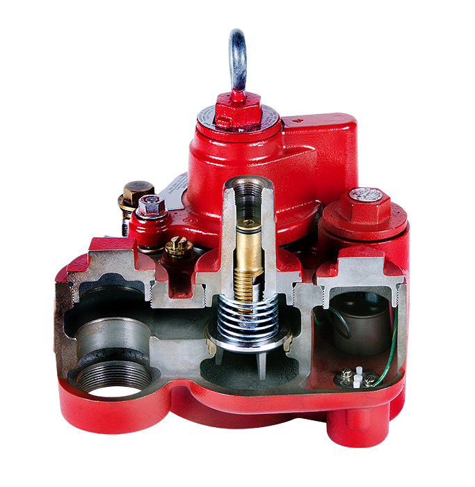
Page 63: Appendix A: Check Valve/Air Purge Screw Operation
Appendix A: Check Valve/Air Purge Screw Operation This appendix discusses the theory of operation of the Red Jacket STP’s check valve and air purge screw. Check Valve Operation Pump On As shown in the check valve cutaway diagram in Figure A-1, when the pump is On, the check valve is opened by fuel flow.
-
Page 64
Appendix A Check Valve Operation Locking Down Check Valve for Line Testing Turning the service screw all the way clockwise, seals the relief valve and at the same time locks down and seals the check valve as shown in Figure A-3. The line is now isolated for pressure testing. Service screw Service screw full down seals off check valve… -
Page 65
Appendix A Check Valve Operation How the Service Screw Lifts the Check Valve When you turn the service screw clockwise 7.5 turns to push open the relief valve stem, a slightly compressible snap ring in the service screw squeezes past a rim on the inside of the top edge of the check valve as shown in Figure A-5. -
Page 66
Appendix A Air Purge Screw Operation Air Purge Screw Operation The air purge screw is used to rid air from the line and manifold hydraulic cavities after opening a port in the manifold (e.g., after installing a line leak detector). When repairs to the pump have been made, the technician will need to purge the air within the manifold as shown in diagram 1 of Figure A-6. -
Page 67: Appendix B: Hardware/Seal Kit O-Ring Gauge
Appendix B: Hardware/Seal Kit O-Ring Gauge…
-
Page 68: Appendix C: Settings For Motor Protection Device
Appendix C: Settings For Motor Protection Device When the submersible pumping unit (UMP) is installed in areas where Category 1 equipment is required, the use of a Motor-Protective Circuit-Breaker (Manual Motor Protector) with phase failure protection is necessary to meet Category 1 requirements.
-
Page 69
Россия, 196247, Санкт-Петербург, Ленинский проспект, дом 160, офис 419. ОГРН: 1057812478790. Телефон: +7 (812) 370-46-63. Адрес электронной почты: info@ gilbarco.ru ИЗГОТОВИТЕЛЬ Veeder-Root Company, 2709 Route 764, Duncansville, PA 16635, США. ій Электронасосные погружные агрегаты Red Jacket и Red Jacket LPG Prem ier ПРОДУКЦИЯ… -
Page 70
ТАМОЖЕННЫЙ СОЮЗ ПРИЛОЖЕНИЕ RU C-US.AA87.B.01125 Лист 1 К СЕРТИФИКАТУ СООТВЕТСТВИЯ №ТС Серия RU № 0 4 9 6 7 І 8 НАЗНАЧЕНИЕ И ОБЛАСТЬ ПРИМЕНЕНИЯ Электронасосные погружные агрегаты Red Jacket и Red Jacket LPG Premier (далее — электронасосы) предназначены для перекачки… -
Page 71
ТАМОЖЕННЫЙ СОЮЗ ПРИЛОЖЕНИЕ RU C-US.AA87.B.01125 Лист 2 К СЕРТИФИКАТУ СООТВЕТСТВИЯ №ТС Серия RU № 0 4 9 6 7 1 9 Электронасос Red Jacket LPG Premier выполнен в виде трубы, внутри которой расположен электродвигатель V4L307, V4L507 (с Ex-маркировкой Ex d НА U), который с одной стороны соединяется соосно с насосом LPG-17 или LPG-21 или LPG-24, а… -
Page 72
For technical support, sales or other assistance, please visit: www.veeder.com…
-
Contents
-
Table of Contents
-
Bookmarks
Quick Links
Revision: H
Manual No: 577014-049
●
The Red Jacket
4″ Submersible Turbine Pump
380 — 415 V, 3 Phase, 50 Hz
Installation, Operation And Service
®
®
Red Jacket
Quick-Set
Submersible Pump
Related Manuals for Veeder-Root Red Jacket Quick-Set
Summary of Contents for Veeder-Root Red Jacket Quick-Set
-
Page 1
Revision: H Manual No: 577014-049 ● The Red Jacket 4” Submersible Turbine Pump 380 — 415 V, 3 Phase, 50 Hz Installation, Operation And Service ® ® Red Jacket Quick-Set Submersible Pump… -
Page 2
Notice Veeder-Root makes no warranty of any kind with regard to this publication, including, but not limited to, the implied warranties of merchantability and fitness for a particular purpose. Veeder-Root shall not be liable for errors contained herein or for incidental or consequential damages in connection with the furnishing, performance, or use of this publication. -
Page 3: Table Of Contents
Table of Contents Introduction Overview ………………………1 Newly designed safety features of The Red Jacket STP ………1 Service spill elimination ………………..1 Vacuum monitoring applications…………….1 Plug-in yoke electrical connection …………….1 Extractable is easy to service ……………….2 Manifold allows for vertical or horizontal discharge ……….2 Built-in contractor’s box ………………..2 Line leak detection facility………………2 Safety Precautions ………………….3…
-
Page 4
Table of Contents Replacing the Check Valve Assembly …………….34 Kits Required: ………………….34 Procedure: ………………….34 Replacing the Conduit Bushing ………………36 Parts Required:…………………..36 Procedure: ………………….36 Replacing the Pigtail …………………..37 Kits Required: ………………….37 Procedure: ………………….37 Replacing the Packer-to-Manifold Wiring Connectors …………40 Kits Required: ………………….40 Procedure: ………………….40 Replacing the Air Purge Screw ………………45 Kits Required: ………………….45… -
Page 5
Table of Contents Figure 18. Suggested Wiring For Three Phase Tandem Pumps ……23 Figure 19. Siphon Connection …………….24 Figure 20. Siphon Ports ………………25 Figure 21. Inserting Siphon Assembly Into Manifold ……….25 Figure 22. Locating Discharge Port Plug For Line Leak Transducer …..26 Figure 23. -
Page 6
Table of Contents Table 13. 410154-001 Hardware/Seal Kit Parts List ……….53 Table 14. 410694-001 Electrical Connector Kit Parts List ……..54 Table 15. 410697-001 UMP Wire Termination And Sealing Kit Parts List ….54 Table 16. 410485-001 Die Spring Kit Parts List …………55 Table 17. -
Page 7: Overview
Introduction Overview The Red Jacket Submersible Turbine Pump (STP) assembly for international markets is engineered for advanced safety, environmental protection, serviceability and flow. The Red Jacket STP fits 4-inch NPT threaded thin-wall risers and is available in a variety of horsepowers and lengths. NOTICE This information is generated as a consequence of carrying out the ignition hazard assessment.
-
Page 8: Extractable Is Easy To Service
Line leak detection facility A connection port for Veeder-Root/Red Jacket industry leading pressurized line leak detection (PLLD) provides environmental compliance without the fuel flow restrictions of mechanical (MLLD) or electronic (ELLD) systems. The port also provides required connection features for MLLD and ELLD detectors.
-
Page 9: Safety Precautions
Introduction Safety Precautions Safety Precautions The following safety symbols are used throughout this manual to alert you to important safety hazards and precautions. EXPLOSIVE FLAMMABLE Fuels and their vapors are extremely explosive if Fuels and their vapors are extremely flammable. ignited.
-
Page 10: Warnings And Instructions
Introduction Warnings and Instructions WARNING This product operates in the highly combustible atmosphere of a gasoline storage tank. FAILURE TO COMPLY WITH THE FOLLOWING WARNINGS AND SAFETY PRECAUTIONS COULD CAUSE DAMAGE TO PROPERTY, ENVIRONMENT, RESULTING IN SERIOUS INJURY OR DEATH. 1.
-
Page 11: Requirements For Use
• The selection of any Veeder-Root product must be based upon physical specifications and limitations and the product’s compatibility with the materials to be handled. Veeder-Root makes no warranty of fitness for a particular purpose.
-
Page 12
– SPECIAL CONDITIONS FOR SAFE USE (EN 15268 Compliant) • ATEX Directive 2014/34/EU approved Red Jacket Submersible Turbine Pump Assemblies shall be marked with the following information: Manufacturer: Veeder-Root Company 2709 Route 764 Duncansville, PA 16635 U.S.A. Marking: Type series… -
Page 13: Regulatory Approvals
Introduction Regulatory Approvals Regulatory Approvals All models of The Red Jacket are UL and cUL listed. Fuel Compatibilities Pumps are designed to operate in a Class 1, Group D atmosphere and in accordance with CENELEC standard EN 15268 and the European Directive 2014/34/EU “Equipment for Potentially Explosive Atmospheres” (Ex II 1/2 G IIA T3).
-
Page 14: Installation And Manifold Dimensions
Introduction Installation and Manifold Dimensions Installation and Manifold Dimensions Figure 1 shows several views and dimensions of The Red Jacket Packer/Manifold. Check valve pressure Line test port Contractor’s box release with threaded entry Line leak 7.7» (196 mm) installation detection port radius (15.4» [392 mm] diameter) Air purge screw…
-
Page 15: Recommended Floating Suction Installation
Figure 2 is an example of a floating suction installation. The floating suction arm can be mounted to pump previous to installing in tank. NOTICE Veeder-Root supplies adapter only, not the apparatus. Manhole: Opening for gauging and should be larger than manhole…
-
Page 16: Dimensions For Pump Selection
Introduction Dimensions for Pump Selection Dimensions for Pump Selection The Red Jacket features an adjustable column pipe and electrical conduit that allows the overall length to be adjusted to a wide range of overall pump lengths. By loosening a collet on the column pipe, the length of the pump may be varied by extending or retracting the column pipe.
-
Page 17: Specifications
Introduction Specifications Distance between centerline of UMP and centerline of bottom fill tube should be 3 feet (914 NOTICE mm) minimum. Air locking of pump after product delivery may occur at distances less than this. Specifications Table 2 shows the adjustable pump lengths by model Table 2.
-
Page 18
Introduction Specifications The weights and lengths listed below are approximate values and will vary due to manufac- NOTICE turing tolerances. The optional trapper intake screen is available as a field installed accessory. Trapper options will increase the length of the UMP by 3.3 inches (83 mm). For installation instructions, see Red Jacket installation instructions #051-256-1. -
Page 19: Installation
Installation Attaching the UMP Table 6 lists the applicable UMPs for each packer/manifold. Table 6. UMP And Packer/Manifold Combinations Packer/Manifold AGP200S17-4RJ1, RJ2, RJ3 AGUMP200S17-4 AGP75S17-3RJ1, RJ2, RJ3 AGUMP75S17-3 P75U17-3RJ1, RJ2, RJ3 UMP75U17-3 AGP150S17-3RJ1, RJ2, RJ3 AGUMP150S17-3 P150U17-3RJ1, RJ2, RJ3 UMP150U17-3 X4AGP150S17RJ1, RJ2, RJ3 X4AGUMP150S17 X4P150U17RJ1, RJ2, RJ3…
-
Page 20: Figure 6. Verifying Pigtail’s Female Connector Is Seated Properly
Installation Attaching the UMP Pigtail female connector/indexing tab is out of its socket — this is the incorrect position when attaching the UMP! Pigtail female connector/index- ing tab is fitted in notch of its socket — this is the correct position when attaching the UMP! Connector’s o-ring…
-
Page 21: Installing The Pump
Installation Installing the Pump Fasteners are not metric — use fasteners provided with equipment. WARNING Installing the Pump • The Red Jacket STP is designed to operate in a Class 1, Group D atmosphere and in accordance with CENELEC standard EN 15268 and the European Directive 2014/34/EU “Equipment for Potentially Explosive Atmospheres”…
-
Page 22: Figure 9. Loosening Locking Nut
Installation Installing the Pump A slight twisting of the UMP will loosen the seals and facilitate adjusting it to the correct NOTICE length. Do not rotate piping beyond 1/4 turn. 1/4 turn maximum on piping rjpumps/fig8.eps Figure 9. Loosening Locking Nut 5.
-
Page 23: Figure 11. Locating Return Line Fitting On Packer
Installation Installing the Pump 2″ discharge port Siphon return line barbed fitting Power wiring compression bushing 3/4”- 14 NPT rjpumps/fig33.eps Figure 11. Locating Return Line Fitting On Packer 8. Lay the siphon return line tubing beside the column pipe. Stop 1 — 3 inches (25 — 76 mm) above the discharge head.
-
Page 24
Installation Installing the Pump Separation of Zone 0 and Zone 1 is accomplished by the male connector partition wall WARNING between the packer and manifold connection. Connection of the UMP wiring is within the Zone 0 boundary and Increased Safety measures inside the flameproof enclosure must be ensured during field wiring connections. -
Page 25: Wiring Power From The Panel To The Red Jacket Stp
Installation Wiring Power from the Panel to the Red Jacket STP Remove cover to access packer wiring compartment Male connector in packer housing Female connector in manifold housing UMP pigtail wires Figure 13. Connecting UMP To Packer Wiring Wiring Power from the Panel to the Red Jacket STP WARNING Disconnect, lock out, and tag the power at the panel before servicing the pump.
-
Page 26: Figure 14. Power Wiring Enters Through Compression Bushing
Installation Wiring Power from the Panel to the Red Jacket STP bushing assembly down over the power wires until it seats in its socket in the base of the manifold’s contractor box leaving sufficient wire lengths for connecting to the pump wires and then tighten the two screws in bushing assembly securely to compress the bushing and seal the wiring entry.
-
Page 27: Connecting To The External Equipotential Bonding Terminal
Installation Connecting to the External Equipotential Bonding Terminal The ATG terminal will be the same voltage and phase as the power supplied to the L1 terminal. 240 V Coil 240 V Coil 240 V Isotrol To 380-415V Supply To 380-415V Supply Dispenser Manual Motor Manual Motor…
-
Page 28: Installing Two Pumps For Tandem Operation
Installation Installing Two Pumps for Tandem Operation External equipotential bonding terminal Figure 16. Equipotential Bonding Terminal Installing Two Pumps for Tandem Operation When greater flow rates are needed, two pumps may be installed in the same piping system by means of a manifold.
-
Page 29: Wiring Three Phase Tandem Pumps
Installation Wiring Three Phase Tandem Pumps Wiring Three Phase Tandem Pumps Figure 18 shows the wiring schematic which allows both three phase STPs to operate simultaneously with any combination of dispensers turned on. 240 V Coil 240 V Coil To 380-415V Supply To 380-415V Supply Manual Motor Manual Motor…
-
Page 30: Siphon Ports
Installation Siphon Ports Siphon Ports The siphon port for The Red Jacket STP is in a siphon assembly that fits into one of the two vacuum ports (see Figure 19). The port end can be swiveled after loosening the hex on top to accommodate the incoming siphon tube.
-
Page 31
Installation Installing a Siphon Assembly Service screw — accessible after removing protective plug Air purge screw Spare vacuum port Siphon port — attach siphon tubing here Siphon cartridge rjpumps/fig20.eps Figure 20. Siphon Ports 6. Remove the 1/4’’ NPT plug from the siphon outlet port and attach siphon system tubing. WARNING Before installing pipe threads, apply an adequate amount of fresh, UL classified for petroleum, non-setting thread sealant. -
Page 32: Installing An Electronic Line Leak Detector Transducer Or Mechanical Lld
Installation Installing an Electronic Line Leak Detector Transducer or Mechanical LLD Installing an Electronic Line Leak Detector Transducer or Mechanical LLD WARNING Disconnect, lock out, and tag power at the panel before servicing the pump. When servicing equipment, use non-sparking tools and use caution when removing or in- stalling equipment to avoid generating a spark.
-
Page 33: Initial Start Up Of Pump
Installation Initial Start Up of Pump Initial Start Up of Pump 1. If a ball valve is installed down line from the pump, close it. 2. Open the air purge screw 2 — 3 turns counterclockwise (see Figure 19). WARNING The air purge screw is retained by a hitch pin to limit travel.
-
Page 34: Checking Relief Pressure At The Pump
Installation Checking Relief Pressure at the Pump Checking Relief Pressure at the Pump WARNING Disconnect, lock out, and tag power at the panel before servicing the pump. When servicing equipment, use non-sparking tools and use caution when removing or in- stalling equipment to avoid generating a spark.
-
Page 35: Testing The Line
Installation Testing the Line Testing the Line WARNING Disconnect, lock out, and tag power at the panel before servicing the pump. When servicing equipment, use non-sparking tools and use caution when removing or installing equipment to avoid generating a spark. Equipment required: •…
-
Page 36: Testing The Tank
Installation Testing the tank Testing the tank WARNING Disconnect, lock out, and tag power at the panel before servicing the pump. When servicing equipment, use non-sparking tools and use caution when removing or installing equipment to avoid generating a spark. Equipment required: •…
-
Page 37: Service And Repair
Service And Repair Replacing the UMP WARNING Disconnect, lock out, and tag power at the panel before servicing the pump. When servicing equipment, use non-sparking tools and use caution when removing or installing equipment to avoid generating a spark. Kit Required: •…
-
Page 38
Service And Repair Replacing the UMP 6. Remove the old UMP by removing the four bolts holding the discharge head as shown in Figure 27. Discard the old gasket and fasteners. 7. Visually inspect the pigtail connector in the discharge head — replace if damaged. Be certain the indexing tab of the pigtail is seated in the notch of the discharge head. -
Page 39
Service And Repair Replacing the UMP Use hand force to push the UMP onto the discharge head. If the UMP does not seat WARNING snug against the discharge head, remove the UMP and correct the problem. 11. Install the four UMP retaining bolts and lock washers. Snug and then torque the bolts using a cross pattern technique to 7 ft-lbs (11 N•m). -
Page 40: Replacing The Check Valve Assembly
Service And Repair Replacing the Check Valve Assembly 14. Reinstall the extractable unit into the manifold and tank. Torque the extractable lock-down nuts in an alternating pattern to 50 ft-lbs (68 N•m). Remove the springs around the lock-down studs and replace with the springs from the kit. NOTICE 15.
-
Page 41
Service And Repair Replacing the Check Valve Assembly 7. Replace the protective plug over the service screw and fully thread into place to ensure a good seal. 8. Open the air purge screw 2 — 3 turns counterclockwise (see Figure 26). WARNING The air purge screw is retained by a hitch pin to limit travel. -
Page 42: Replacing The Conduit Bushing
Service And Repair Replacing the Conduit Bushing Replacing the Conduit Bushing WARNING Disconnect, lock out, and tag power at the panel before servicing the pump. When servicing equipment, use non-sparking tools and use caution when removing or in- stalling equipment to avoid generating a spark. Parts Required: •…
-
Page 43: Replacing The Pigtail
Service And Repair Replacing the Pigtail Replacing the Pigtail WARNING Disconnect, lock out, and tag power at the panel before servicing the pump. When servicing equipment, use non-sparking tools and use caution when removing or installing equipment to avoid generating a spark. Kits Required: •…
-
Page 44
Service And Repair Replacing the Pigtail 7. Remove the packer wiring compartment cover. Remove and discard the O-ring from the cover and set aside the cover. Observe the three wiring connections sealed in the compartment. Make a note of which wire from the packer connects to which wire from the pigtail (it should be like colored wires connecting to like colored wires). -
Page 45
Service And Repair Replacing the Pigtail 18. Insulate the three connections by placing each by itself into an epoxy sealant bag following steps A, B, C below. From pigtail To male connector Only one connection Tie wrap per bag. Wire insulation is fully into epoxy Butt splice Instructions:… -
Page 46: Replacing The Packer-To-Manifold Wiring Connectors
Service And Repair Replacing the Packer-to-Manifold Wiring Connectors Replacing the Packer-to-Manifold Wiring Connectors WARNING Disconnect, lock out, and tag power at the panel before servicing the pump. When servicing equipment, use non-sparking tools and use caution when removing or installing equipment to avoid generating a spark. Kits Required: •…
-
Page 47
Service And Repair Replacing the Packer-to-Manifold Wiring Connectors Male connector’s indexing pin Male connector Male connector’s retaining washer Female connector rjpumps/fig42.eps Wiring to UMP Figure 32. Packer-To-Manifold Wiring Connectors 7. Use a pair of needle-nose pliers or long-nose locking pliers to remove the retaining washer that holds the male connector in its socket. -
Page 48
Service And Repair Replacing the Packer-to-Manifold Wiring Connectors Place a mark on the facing rjpumps/fig44.eps of the packer using a felt pen to indicate the position of the index hole Hole to receive male connector’s indexing pin Figure 34. Male Connector Index Hole In Base Of Socket 12. -
Page 49
Service And Repair Replacing the Packer-to-Manifold Wiring Connectors Indexing pin in hole Retaining washer flat side against connector about 1-3/8» (35mm) Packer facing Retaining View A-A washer 045-3 Figure 36. Correct Depth Of Male Connector In Packer Socket 15. Strip insulation off all six wires 5/16 of an inch (8mm). 16. -
Page 50
Service And Repair Replacing the Packer-to-Manifold Wiring Connectors 21. Remove capacitor access cover (see Figure 37). Remove and discard the O-ring from the cover and set aside the cover. Observe the three wiring connections from the female connector. Make a note of which wire from the connector connects to which wire from the incoming power wiring. -
Page 51: Replacing The Air Purge Screw
Service And Repair Replacing the Air Purge Screw extra care to distinguish each one before replacing them in the extractable. Lubricate each O-ring with petroleum jelly and then install them in their assigned grooves in the extractable (see Figure 29 on page 33). 29.
-
Page 52
Service And Repair Replacing the Air Purge Screw 8. Lubricate the three O-rings on the new screw with petroleum jelly and install it with the hitch pin pushed on and hanging in the vertical position (see Figure 41). Service screw (beneath protective plug) Check valve housing 2-inch port Air purge screw… -
Page 53
Service And Repair Replacing the Air Purge Screw Hitch pin in retaining position Hitch pin ready for screw removal Use your forefinger to push the pin all the way in Figure 40. Reorienting The Air Purge Screw’s Hitch Pin Upper o-ring (-015 [0.551» ID x 0.070» wide]) Middle o-ring (-014 [0.489» ID x 0.070» wide]) Lower o-ring (-903 [0.301» ID x 0.064» wide]) Figure 41. -
Page 54
Service And Repair Replacing the Air Purge Screw Push the hitch pin’s up with one forefinger. While holding the pin up with one forefinger position the gloved forefinger of the other hand Note that the crimped leg of the pin is facing against the other end of the pin. -
Page 55: Parts Lists
Parts Lists Customer Service Number After unpacking the equipment, please inspect the parts. Make sure all accessories are included and that no damage occurred during shipping. Report any damage to the shipper immediately and inform a customer service representative at 1-800-873-3313 of any equipment damage or missing parts. Pump Parts Table 7 lists the international pump parts list.
-
Page 56
Parts Lists Pump Parts Table 7. International Pump Parts List Item (ref. Figure 43) Part No. Description INTL 410156-001 20 ft. pigtail 410184-034 UMP75U17-3 W/2″ Discharge head 410184-036 UMP150U17-3 W/2″ Discharge head 410184-038 X4UMP150U17 W/2″ Discharge head 410184-033 UMP75U17-3 410184-035 UMP150U17-3 410184-041 AGUMP75S17-3… -
Page 57: Siphon Cartridge Kit Parts
Parts Lists Siphon Cartridge Kit Parts Siphon Cartridge Kit Parts Table 8 lists the 410151-001 Siphon Cartridge Kit & 410151-002 AG Siphon Cartridge Kit parts lists. Table 8. Siphon Cartridge Kit Parts List Item (ref. Figure 44) Part No. Description Qty.
-
Page 58: Check Valve Kit Parts
Parts Lists Check Valve Kit Parts Check Valve Kit Parts Table 10 lists the 410153-001 Check Valve Kit parts list. Table 10. 410153-001 Check Valve Kit Parts List Item (ref. Figure 46) Part No. Description Qty. 410022-005 Poppet assembly — check relief valve 410753-001 Spring Table 11 lists the 410153-002 Hi Pressure Check Valve Kit parts list.
-
Page 59: Hardware/Seal Kit Parts
Parts Lists Hardware/Seal Kit Parts Hardware/Seal Kit Parts Table 13 lists the 410154-001 Hardware/Seal Kit parts list. Table 13. 410154-001 Hardware/Seal Kit Parts List (Ref. Figure) Part No. Description Qty. Figure 29 on page 33 072-541-1 O-ring — 118-FKM Figure 30 on page 35 072-578-1 O-ring — 225-FKM Figure 30 on page 35…
-
Page 60: Electrical Connector Kit Parts
Parts Lists Electrical Connector Kit Parts Electrical Connector Kit Parts Table 14 lists the 410694-001 Electrical Connector Kit parts list. Table 14. 410694-001 Electrical Connector Kit Parts List Item (ref. Figure 49) Part No. Description Qty. 410607-001 Connector — male 410117-001 Connector — electrical 072-541-1…
-
Page 61: Die Spring Kit Parts
Parts Lists Die Spring Kit Parts Figure 50. UMP Wire Termination And Sealing Kit Die Spring Kit Parts Table 16 lists the 410485-001 Die Spring Kit parts list. Table 16. 410485-001 Die Spring Kit Parts List Item (ref. Figure 51) Part No.
-
Page 62: Air Purge Screw Kit Parts
Parts Lists Air Purge Screw Kit Parts Air Purge Screw Kit Parts Table 17 lists the 410484-001 Air Purge Screw Kit parts list. Table 17. 410484-001 Air Purge Screw Kit Parts List Item (ref. Figure 52) Part No. Description Qty. 410064-001 O-ring-015-FKM 410134-002…
-
Page 63: Appendix A: Check Valve/Air Purge Screw Operation
Appendix A: Check Valve/Air Purge Screw Operation This appendix discusses the theory of operation of the Red Jacket STP’s check valve and air purge screw. Check Valve Operation Pump On As shown in the check valve cutaway diagram in Figure A-1, when the pump is On, the check valve is opened by fuel flow.
-
Page 64
Appendix A Check Valve Operation Locking Down Check Valve for Line Testing Turning the service screw all the way clockwise, seals the relief valve and at the same time locks down and seals the check valve as shown in Figure A-3. The line is now isolated for pressure testing. Service screw Service screw full down seals off check valve… -
Page 65
Appendix A Check Valve Operation How the Service Screw Lifts the Check Valve When you turn the service screw clockwise 7.5 turns to push open the relief valve stem, a slightly compressible snap ring in the service screw squeezes past a rim on the inside of the top edge of the check valve as shown in Figure A-5. -
Page 66
Appendix A Air Purge Screw Operation Air Purge Screw Operation The air purge screw is used to rid air from the line and manifold hydraulic cavities after opening a port in the manifold (e.g., after installing a line leak detector). When repairs to the pump have been made, the technician will need to purge the air within the manifold as shown in diagram 1 of Figure A-6. -
Page 67: Appendix B: Hardware/Seal Kit O-Ring Gauge
Appendix B: Hardware/Seal Kit O-Ring Gauge…
-
Page 68: Appendix C: Settings For Motor Protection Device
Appendix C: Settings For Motor Protection Device When the submersible pumping unit (UMP) is installed in areas where Category 1 equipment is required, the use of a Motor-Protective Circuit-Breaker (Manual Motor Protector) with phase failure protection is necessary to meet Category 1 requirements.
-
Page 69
Россия, 196247, Санкт-Петербург, Ленинский проспект, дом 160, офис 419. ОГРН: 1057812478790. Телефон: +7 (812) 370-46-63. Адрес электронной почты: info@ gilbarco.ru ИЗГОТОВИТЕЛЬ Veeder-Root Company, 2709 Route 764, Duncansville, PA 16635, США. ій Электронасосные погружные агрегаты Red Jacket и Red Jacket LPG Prem ier ПРОДУКЦИЯ… -
Page 70
ТАМОЖЕННЫЙ СОЮЗ ПРИЛОЖЕНИЕ RU C-US.AA87.B.01125 Лист 1 К СЕРТИФИКАТУ СООТВЕТСТВИЯ №ТС Серия RU № 0 4 9 6 7 І 8 НАЗНАЧЕНИЕ И ОБЛАСТЬ ПРИМЕНЕНИЯ Электронасосные погружные агрегаты Red Jacket и Red Jacket LPG Premier (далее — электронасосы) предназначены для перекачки… -
Page 71
ТАМОЖЕННЫЙ СОЮЗ ПРИЛОЖЕНИЕ RU C-US.AA87.B.01125 Лист 2 К СЕРТИФИКАТУ СООТВЕТСТВИЯ №ТС Серия RU № 0 4 9 6 7 1 9 Электронасос Red Jacket LPG Premier выполнен в виде трубы, внутри которой расположен электродвигатель V4L307, V4L507 (с Ex-маркировкой Ex d НА U), который с одной стороны соединяется соосно с насосом LPG-17 или LPG-21 или LPG-24, а… -
Page 72
For technical support, sales or other assistance, please visit: www.veeder.com…
Погружной турбинный насос Red Jacket – самый популярный насос в мире. Это самая высокая производительность и скорость потока топлива, самое низкое энергопотребление среди аналогов. Производится с 1878 г. Это продукт, о котором говорят «сделан на совесть».
Безупречная конструкция
- Высокая скорость подачи топлива, низкое энергопотребление, повышенная надежность и безопасность.
- Улучшенная конструкция корпуса и разъема обеспечивает больший тракт прохождения топлива и увеличение скорости потока на 5%.
- Двигатель с улучшенным КПД позволяет снизить потребляемую мощность на 8%.
- Улучшение качества сборки и технических характеристик означает повышение коэффициента непрерывной эксплуатации. Эти показатели значительно опережают показатели аналогов на рынке.
- Универсальная совместимость – меньше запчастей.
- Улучшенная конструкция корпуса и изоляции повышает надежность изделия и обеспечивает более долгий срок службы.
- Постоянная рабочая температура насоса на 125 градусов меньше, чем у аналогов, что повышает его безопасность и отвечает самым последним нормам противопожарной безопасности.
Улучшенная конструкция съемной части
- Быстрый монтаж, простое обслуживание и проверка задают стандарты электробезопасности и экологичности:
- Встроенный изолированный блок переключателя: корпус электрических соединений встроен в съемную часть и полностью изолирован от топливного тракта.
- Простой монтаж и обслуживание не требуют регулировки и ускоряют процесс сборки.
- Повышенная электробезопасность: электрическое соединение автоматически разрывается при демонтаже съемных креплений.
- Автоматическое отсоединение изоляционного слоя при демонтаже съемных креплений обеспечивает автоматический возврат топлива в резервуар, что предотвращает его разлив и гарантирует экологическую безопасность.
- Инновационная конструкция контрольного клапана: установка «в открытую» облегчает проверку на линии и обслуживание.
| Характеристика | Значение |
|---|---|
| Совместимость с сортами топлива | Дизель, Бензин 100%, Бензин 80% с 20% содержанием этанола, метанола, МТАЭ, ЭБТЭ или МТБЭ |
| Электропитание | 3-фазное, 50Гц, 380 – 415 В переменного тока |
| ДКЗ насоса | 100 мм над входным каналом |
| Сертификация | |
| ATEX | II 1/2 G EN15268 IIA T3 DEMKO 12 ATEX 1247797 X |
| Специальные условия для безопасного использования | См. руководство 577014-049 по установке, требованиям по эксплуатации и обслуживания |
-

Прайс-лист на продукцию
-
Red Jacket 4 дюйма. Технические характеристики.
-
Каталог оборудования
-
Опросный лист

-
ИННОВАЦИИ
Большинство технологий и инноваций в сфере топливораздаточного оборудования разработано специалистами компании. Вот некоторые из них: система измерения топлива, турбинные насосы, объемомер Ecometer, до сих пор не имеющий аналогов.
-
КАЧЕСТВО
Учитывая специфику отрасли компании GILBARCO VEEDER-ROOT, потребности рынка и технологические тренды, компания уделяет внимание не только качеству исполнения продукции, но и возможности ее эффективного использования в далекой перспективе.
-
ИСТОРИЯ
История компании GILBARCO VEEDER-ROOT начинается в 1865 году, когда Джон Баркер и Чарльз Гилберт начинают строительство «Спрингфилдской топливной машины», которая должна была вырабатывать газовые пары из сырой нефти.
-

Топливораздаточные колонки
SK700-II, Horizon и др.
-
Зарядные станции
Veefil-RT и др.
-
Автоматические уровнемеры
TLS4, TLS4B и др.
-
Погружные насосы
Red Jacket и др.
-
Управление АЗС
POS, BOS и др.
-
Терминалы
FlexPay NP3 и др.
-
Системы мониторинга
Insite360 Fuel Suite и др.
-
Запасные части
Encore 510 и др.


Обратитесь к нам или региональному дилеру для получения более подробной информации о сертификатах, характеристиках, отзывах, стоимости, наличии на складе и сроках поставки оборудования Gilbarco.
Мы гарантируем ответ в течение 8 рабочих часов!
адрес для заявок: gcr@nt-rt.ru
-

029 — Громова Марина
Здравствуйте! Я могу вам чем-то помочь?

Оператор набирает сообщение
Здравствуйте! Какая продукция Вас интересует?
Задайте вопрос прямо сейчас:
- Home
- Погружные насосы Red Jacket
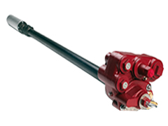
Погружные турбинные насосы серии Red Jacket®
Насосы Red Jacket® — это сердце заправочной инфраструктуры. Модельный ряд погружных насосов задает стандарты высокого качества и надежности устройств для АЗС.
Отправить запрос
Погружные насосные системы Red Jacket®
Red Jacket® STP
Red Jacket® AG STP
Red Jacket® LPG Premier
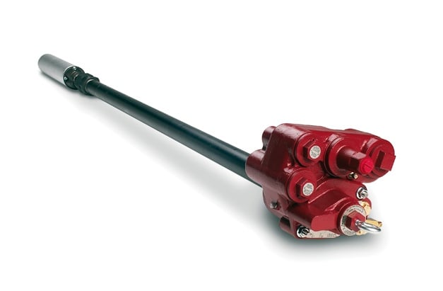
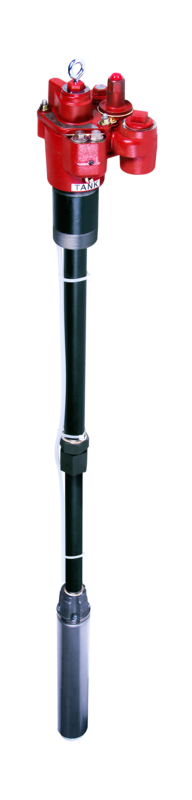
Погружной турбинный насос Red Jacket®
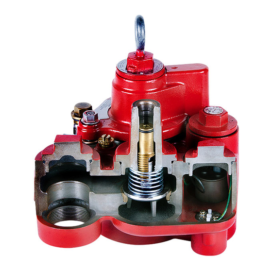
Погружной турбинный насос Red Jacket – самый популярный насос в мире. Это самая высокая производительность и скорость потока топлива, самое низкое энергопотребление среди аналогов. Производится с 1878 г. Это продукт, о котором говорят «сделан на совесть».
Характеристики
Широкий выбор опций
3-фазные насосы мощностью ¾, 1½ или 2 л.с., что позволяет применять их на самых разных АЗС.
Напорная технология
Меньшее количество труб и подвижных частей в гидравлической системе по сравнению со всасывающей технологией, без риска образования воздушных пробок.
Стабильные параметры потока
Эффективная перекачка топлива на большие расстояния, в том числе в условиях высокой окружающей температуры и большого перепада высот.
Интегрированный контроль утечек из напорной линии
Механический или электронный контроль утечек из напорной линии с помощью систем Veeder-Root TLS с функцией автоматического отключения насоса для обеспечения безопасности окружающей среды.
Уникальная конструкция съемной части
При демонтаже контрольный клапан, датчик утечек и сифонный картридж остаются в пакере и не требуют отсоединения.
Обеспечение безопасности труда
Электрическое соединение автоматически разрывается при демонтаже съемной части и топливо в пакере и неизолированном трубопроводе безопасно возвращается в резервуар, что предотвращает его разлив и снижает сервисные затраты.
Вертикальный выход топлива
Обеспечивается простое подключение к горизонтальному трубопроводу с помощью стандартных трубных фитингов.
Два сифонных порта
Два порта сифонных картриджей позволяют подключать несколько резервуаров к одному насосу. Уникальная шарнирная конструкция обеспечивает легкость подключения.
Блокируемый контрольный клапан
Легкость сброса давления и безопасного слива неизолированного топлива в пакере и линии обратно в резервуар для проверок или технического обслуживания системы.
Преимущества
Безупречная конструкция
- Высокая скорость подачи топлива, низкое энергопотребление, повышенная надежность и безопасность.
- Улучшенная конструкция корпуса и разъема обеспечивает больший тракт прохождения топлива и увеличение скорости потока на 5%.
- Двигатель с улучшенным КПД позволяет снизить потребляемую мощность на 8%.
- Улучшение качества сборки и технических характеристик означает повышение коэффициента непрерывной эксплуатации. Эти показатели значительно опережают показатели аналогов на рынке.
- Универсальная совместимость – меньше запчастей.
- Улучшенная конструкция корпуса и изоляции повышает надежность изделия и обеспечивает более долгий срок службы.
- Постоянная рабочая температура насоса на 125 градусов меньше, чем у аналогов, что повышает его безопасность и отвечает самым последним нормам противопожарной безопасности.
Улучшенная конструкция съемной части
- Быстрый монтаж, простое обслуживание и проверка задают стандарты электробезопасности и экологичности:
- Встроенный изолированный блок переключателя: корпус электрических соединений встроен в съемную часть и полностью изолирован от топливного тракта.
- Простой монтаж и обслуживание не требуют регулировки и ускоряют процесс сборки.
- Повышенная электробезопасность: электрическое соединение автоматически разрывается при демонтаже съемных креплений.
- Автоматическое отсоединение изоляционного слоя при демонтаже съемных креплений обеспечивает автоматический возврат топлива в резервуар, что предотвращает его разлив и гарантирует экологическую безопасность.
- Инновационная конструкция контрольного клапана: установка «в открытую» облегчает проверку на линии и обслуживание.
Технические характеристики
| Погружные турбинные насосы Red Jacket 4” | ||||
| Мощность, лс | 0.75 | 1.5 | 1.5 x 4 | 2.0 |
| Стандартные версии | ||||
| Быстро налаживаемые модели | P75U17-3 RJ1/2/3 | P150U17-3RJ2 | X4P150U17 RJ1/2/3 | P200U17-4 RJ1/2/3 |
| Артикул | 410140-074/5/6 | 410141-076/7/8 | 410143-071/2/3 | 410142-051/2/3 |
| Модели фиксированной длины | P75U17-3 RJ | P150U17-3 RJ | X4P150U17 RJ | P200U17-4 RJ |
| Артикул | 410177-014 | 410177-011 | 410177-012 | 410177-013 |
| Совместимость с сортами топлива | Дизель, Бензин 100%, Бензин 80% с 20% содержанием этанола, метанола, МТАЭ, ЭБТЭ или МТБЭ | |||
| Функциональные характеристики | ||||
| Скорость потока при 0.7 Бар (бензин)l | 200 л/мин | 300 л/мин | 220 л/мин | 330 л/мин |
| Статическое давление (бензин) | 2.4 Бар | 2.5 Бар | 2.8 Бар | 3.1 Бар |
| Монтажные требования | ||||
| Электропитание | 3-фазное, 50Гц, 380 – 415 В переменного тока | |||
| ДКЗ насоса | 100 мм над входным каналом | |||
| Сертификация | ||||
| ATEX | II 1/2 G EN15268 IIA T3 DEMKO 12 ATEX 1247797 X | |||
| Специальные условия для безопасного использования | См. руководство 577014-049 по установке, требованиям по эксплуатации и обслуживания | |||
| Замена на месте для старых моделей | ||||
| Доступно для старых одно- и 3-фазных моделей (см. актуальный прайс-лист) |
Погружной турбинный насос Red Jacket® AG
Серия погружных насосов Red Jacket® AG основана на модели Red Jacket® и специально разработана с учетом агрессивных сред, таких как альтернативное топливо.
Red Jacket® AG совместим с концентрациями этанола и метанола почти на 100%, МТБЭ, ЭТБЭ или МТАЭ почти на 20%, имеет сертификаты по UL79A и UL79B для использования возобновляемого биотоплива.
Технические характеристики
| Погружные турбинные насосы Red Jacket 4” | ||||
| Мощность, лс | 0.75 | 1.5 | 1.5 x 4 | 2.0 |
| Стандартные версии | ||||
| Быстро налаживаемые модели | P75U17-3 RJ1/2/3 | P75U17-3 RJ1/2/3 | X4P150U17 RJ1/2/3 | P200U17-4 RJ1/2/3 |
| Артикул | 410140-074/5/6 | 410141-076/7/8 | 410143-071/2/3 | 410142-051/2/3 |
| Совместимость с сортами топлива | Дизель, Бензин 100%, Бензин 80% с 20% содержанием этанола, метанола, МТАЭ, ЭБТЭ или МТБЭ | |||
| Функциональные характеристики | ||||
| Скорость потока при 0.7 Бар (бензин)l | 200 л/мин | 300 л/мин | 220 л/мин | 330 л/мин |
| Статическое давление (бензин) | 2.4 Бар | 2.5 Бар | 2.8 Бар | 3.1 Бар |
| Монтажные требования | ||||
| Электропитание | 3-фазное, 50Гц, 380 – 415 В переменного тока | |||
| ДКЗ насоса | 100 мм над входным каналом | |||
| Сертификация | ||||
| ATEX | II 1/2 G EN15268 IIA T3 DEMKO 12 ATEX 1247797 X | |||
| Специальные условия для безопасного использования | См. руководство 577014-049 по установке, требованиям по эксплуатации и обслуживания | |||
| Замена на месте для старых моделей | ||||
| Доступно для старых одно- и 3-фазных моделей (см. актуальный прайс-лист) |
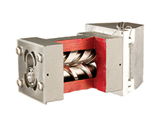
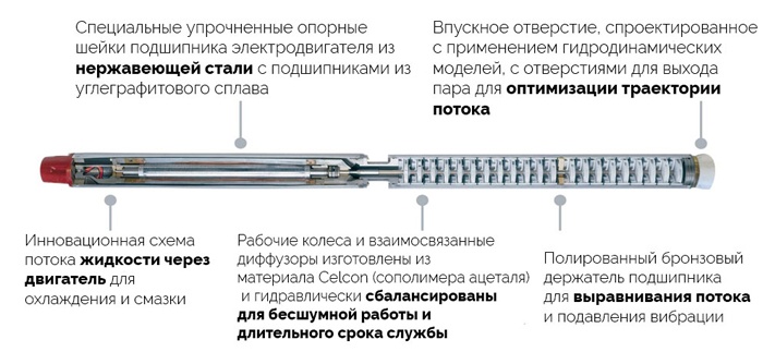
Усовершенствованная конструкция
![]()
Простота монтажа и обслуживания
Технология фиксированных оборотов снижает расходы на монтаж и предотвращает электрические и радиопомехи, создаваемые оборудованием АЗС. Интегрированные соединительные компоненты и клеммная коробка избавляют от необходимости заказа дополнительных компонентов и дальнейшей рационализации процессов.
![]()
Сертификация
Линейка насосов Red Jacket – это сочетание различных решений, которые отвечают самым высоким мировым стандартам и требованиям местных регулирующих органов.
Усиленный контроль

Оптимизация скорости потока
При необходимости вы можете установить дополнительные насосы для оптимизации подачи топлива.

Связь с другими устройствами
Подсоединение к уровнемеру TLS-450PLUS для активации резервуаров на основе настроек параметров топлива в распределительных резервуарах.

Настраиваемый пользовательский доступ
Два насоса Red Jacket с высокой потребляемой мощностью для оптимизации потока топлива и возможности замены одного насоса другим.
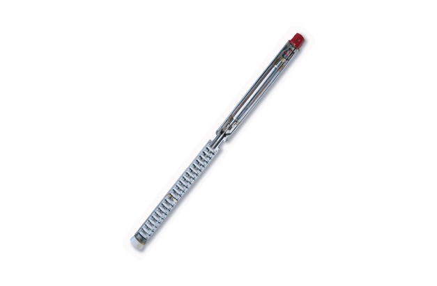
Серия LPG Premier
Самый эффективный способ перекачки СУГ
Нанос обеспечивает бесшумную заправку, поддержание высокой скорости отпуска топлива и устранение воздушных пробок. Дополнителные преимущества: перекачка СУГ на большие расстояния и гибкость в проектировании АЗС.
- Red Jacket Premier – Скорость потока 70 л/мин под давлением 7 бар
- Red Jacket Premier MidFlow — Скорость потока 100 л/мин под давлением 7 бар
- Red Jacket Premier HiFlow — Скорость потока 150 л/мин под давлением 7 бар
Характеристики и преимущества
Red Jacket Premier
- Базовая модель для применения на объектах с небольшой прокачкой.
- Скорость потока 70 литров в минуту под давлением 7 бар.
Red Jacket Premier MidFlow
- Для работы с СУГ с низком или средней скоростью потока.
- Скорость потока 100 л/мин под давлением 7 бар.
Red Jacket Premier HiFlow
- Модель для высокопроизводительных объектов, таких как ведомственные АГЗС и станции по наполнению газовых баллонов.
- Скорость потока 150 л/мин под давлением 7 бар.
Технические характеристики
| Модель | Premier | Premier MidFlow | Premier HiFlow | |
| Скорость потока под давлением 7 Барª | 70 л/мин | 100 л/мин | 150 л/мин | |
| Скорость потока при максимальном КПД | 70 л/мин при 6.8 бар | 130 л/мин при 5.8 бар | 130 л/мин при 8.1 бар | |
| Скорость потока под давлением 4 Барª | 100 litre/min | 170 Litre/min | 190 litre/min | |
| Мотор | В переменного тока | 380-415 | 380-415 | 380-415 |
| Гц | 50 | 50 | 50 | |
| лс | 3 | 3 | 5 | |
| кВт | 2.2 | 2.2 | 3.7 | |
| Кол-во ступеней | 21 | 17 | 24 | |
| Длина, мм | 1506 | 1506 | 1896 | |
| Вес, кг | 39 | 39 | 48 |
К СЕРТИФИКАТУ СООТВЕТСТВИЯ №ТС
Электронасос Red Jacket LPG Premier выполнен в виде трубы, внутри которой расположен электродвигатель V4L307,
V4L507 (с Ex-маркировкой Ex d НА U), который с одной стороны соединяется соосно с насосом LPG-17 или LPG-21 или
LPG-24, а с другой стороны выполнен нагнетательный патрубок, во внутренней части которого расположен разъем для
подключения кабеля через трубный ввод, а по кольцевому зазору между внешней и внутренней трубой протекает
перекачиваемое топливо.
Для тепловой защиты электродвигателей на двух обмотках статора установлены биметаллические выключатели.
Взрывозащищенность электронасосов обеспечивается выполнением требований:
ГОСТ 31441.1-2011 (EN 13463-
взрывоопасных средах. Часть 1. Общие требования,
ГОСТ 31441.3-2011 (EN 13463-3:2005) Оборудование неэлектрическое, предназначенное для применения в потенциально
взрывоопасных средах. Часть 3. Защита взрывонепроницаемой оболочкой «d»,
ГОСТ 31441.5-2011 (EN 13463-5:2003) Оборудование неэлектрическое, предназначенное для применения в потенциально
взрывоопасных средах. Часть 5. Защита конструкционной безопасностью «с»,
ГОСТ 31441.6-2011 (EN 13463-6:2005) Оборудование неэлектрическое, предназначенное для применения в потенциально
взрывоопасных средах. Часть 6. Защита контролем источника воспламенения «Ь».
Взрывозащищенность электродвигателей обеспечивается выполнением требований:
ГОСТ 31610.0-2014 (ІЕС 60079-0:2011) Взрывоопасные среды. Часть 0• Оборудовшіие. Общие требования,
ГОСТ 31610.26-2012 ЛЕС 60079-26:2006 Взрывоопасные среды. Часть 26. Оборудование с уровнем взрывозащиты
оборудования Ga,
ГОСТ ІЕС 60079-1-2011 Взрывоопасные среды. Часть 1. Оборудование с видом взрывозащиты «взрывонепроиицаемые
оболочки «d»,
ГОСТ Р МЭК 60079-7-2012 Взрывоопасные среды. Часть 7. Оборудование. Повышенная защита вида «е»,
ГОСТ Р МЭК 60079-18-2012 Взрывоопасные среды. Часть 18. Оборудование с видом взрывозащиты «герметизация
компаундом «т».
Маркировка, наносимая на электронасосы, включает следующие данные:
—
товарный знак или наименование предприятия — изготовителя;
—
тип изделия, заводской номер и год выпуска;
—
Ех-маркировку;
—
специальный знак взрывобезопасности;
—
диапазон температуры окружающей среды;
—
предупредительные надписи;
—
номер сертификата.
и другие данные, которые изготовитель должен отразить в маркировке, если это требуется технической документацией.
Знак X, стоящий после Ex-маркировки, означает, что при эксплуатации электронасосов необходимо соблюдать
следующие специальные условия:
5.1. Все модели электронасосов и связанное с ними оборудование должны устанавливаться в соответствии с
требованиями по монтажу. Смотри Руководство по эксплуатации 051-327-1, 577014-049.
5.2. При монтаже и техническом обслуживании электронасосов, во избежание опасности возгорания от фрикционных
искр, образующихся при трении или соударении деталей, необходимо использовать инструменты, не создающие искр от
механических ударов согласно Руководствам по эксплуатации 051-327-1, 577014-049.
5.3. Моторно-насосный блок (UMP) и функциональные компоненты системы не подлежат ремонту, а подлежат замене на
соответствующий блок или компонент от производителя в случае повреждения или выхода из строя.
Специальные условия, обозначенные знаком X, должны быть отражены в сопроводительной документации,
подлежащей обязательной поставке в комплекте с каждым электронасосом.
Внесение изменений в согласованные конструкцию электронасосов возможно только по согласованию с
НАНИО ЦСВЭ в соответствии с требованиями ТР ТС 012/2018.
Инспекционный контроль — 2019 г., 2020 г., 2021 г., 2022 г.
Руководитель (уполномоченн<
лицо) органа по сертификации
Эксперт-аудитор (эксперт)
ТАМОЖЕННЫЙ СОЮЗ
ПРИЛОЖЕНИЕ
2001) Оборудование неэлектрическое, предназначенное для применения в потенциально
丨
:
4.
МАРКИРОВКА
5.
СПЕЦИАЛЬНЫЕ УСЛОВИЯ ПРИМЕНЕНИЯ
,2016. дБ» лицензия № 05-05-09/003 ФНС РФ , тел (495) 726 4742. www.opclon.ru
RU C-US.AA87.B.01125 Лист 2
Серия RU
№ 0 4 9 6 7 1 9
Александр Сергеевич
п од пи сь
Чернов Борис Владимирович
и н иц и ал ы , ф ам илия
и н иц и ал ы , ф ам илия
Погружной турбинный насос Red Jacket – самый популярный насос в мире. Это самая высокая производительность и скорость потока топлива, самое низкое энергопотребление среди аналогов. Производится с 1878 г. Это продукт, о котором говорят «сделан на совесть».
Безупречная конструкция
- Высокая скорость подачи топлива, низкое энергопотребление, повышенная надежность и безопасность.
- Улучшенная конструкция корпуса и разъема обеспечивает больший тракт прохождения топлива и увеличение скорости потока на 5%.
- Двигатель с улучшенным КПД позволяет снизить потребляемую мощность на 8%.
- Улучшение качества сборки и технических характеристик означает повышение коэффициента непрерывной эксплуатации. Эти показатели значительно опережают показатели аналогов на рынке.
- Универсальная совместимость – меньше запчастей.
- Улучшенная конструкция корпуса и изоляции повышает надежность изделия и обеспечивает более долгий срок службы.
- Постоянная рабочая температура насоса на 125 градусов меньше, чем у аналогов, что повышает его безопасность и отвечает самым последним нормам противопожарной безопасности.
Улучшенная конструкция съемной части
- Быстрый монтаж, простое обслуживание и проверка задают стандарты электробезопасности и экологичности:
- Встроенный изолированный блок переключателя: корпус электрических соединений встроен в съемную часть и полностью изолирован от топливного тракта.
- Простой монтаж и обслуживание не требуют регулировки и ускоряют процесс сборки.
- Повышенная электробезопасность: электрическое соединение автоматически разрывается при демонтаже съемных креплений.
- Автоматическое отсоединение изоляционного слоя при демонтаже съемных креплений обеспечивает автоматический возврат топлива в резервуар, что предотвращает его разлив и гарантирует экологическую безопасность.
- Инновационная конструкция контрольного клапана: установка «в открытую» облегчает проверку на линии и обслуживание.
| Характеристика | Значение |
|---|---|
| Совместимость с сортами топлива | Дизель, Бензин 100%, Бензин 80% с 20% содержанием этанола, метанола, МТАЭ, ЭБТЭ или МТБЭ |
| Электропитание | 3-фазное, 50Гц, 380 – 415 В переменного тока |
| ДКЗ насоса | 100 мм над входным каналом |
| Сертификация | |
| ATEX | II 1/2 G EN15268 IIA T3 DEMKO 12 ATEX 1247797 X |
| Специальные условия для безопасного использования | См. руководство 577014-049 по установке, требованиям по эксплуатации и обслуживания |
-
Прайс-лист на продукцию
-
Red Jacket 4 дюйма. Технические характеристики.
-
Каталог оборудования
-
Опросный лист
-
ИННОВАЦИИ
Большинство технологий и инноваций в сфере топливораздаточного оборудования разработано специалистами компании. Вот некоторые из них: система измерения топлива, турбинные насосы, объемомер Ecometer, до сих пор не имеющий аналогов.
-
КАЧЕСТВО
Учитывая специфику отрасли компании GILBARCO VEEDER-ROOT, потребности рынка и технологические тренды, компания уделяет внимание не только качеству исполнения продукции, но и возможности ее эффективного использования в далекой перспективе.
-
ИСТОРИЯ
История компании GILBARCO VEEDER-ROOT начинается в 1865 году, когда Джон Баркер и Чарльз Гилберт начинают строительство «Спрингфилдской топливной машины», которая должна была вырабатывать газовые пары из сырой нефти.
-
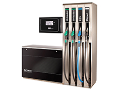
Топливораздаточные колонки
SK700-II, Horizon и др.
-
Зарядные станции
Veefil-RT и др.
-
Автоматические уровнемеры
TLS4, TLS4B и др.
-
Погружные насосы
Red Jacket и др.
-
Управление АЗС
POS, BOS и др.
-
Терминалы
FlexPay NP3 и др.
-
Системы мониторинга
Insite360 Fuel Suite и др.
-
Запасные части
Encore 510 и др.
Обратитесь к нам или региональному дилеру для получения более подробной информации о сертификатах, характеристиках, отзывах, стоимости, наличии на складе и сроках поставки оборудования GILBARCO.
Мы гарантируем ответ в течение 8 рабочих часов!
адрес для заявок: gcr@nt-rt.ru
-
029 — Громова Марина
Здравствуйте! Я могу вам чем-то помочь?
Оператор набирает сообщение
Здравствуйте! Какая продукция Вас интересует?
Задайте вопрос прямо сейчас:
- Home
- Погружные насосы Red Jacket
Погружные турбинные насосы серии Red Jacket®
Насосы Red Jacket® — это сердце заправочной инфраструктуры. Модельный ряд погружных насосов задает стандарты высокого качества и надежности устройств для АЗС.
Отправить запрос
Погружные насосные системы Red Jacket®
Red Jacket® STP
Red Jacket® AG STP
Red Jacket® LPG Premier
Погружной турбинный насос Red Jacket®
Погружной турбинный насос Red Jacket – самый популярный насос в мире. Это самая высокая производительность и скорость потока топлива, самое низкое энергопотребление среди аналогов. Производится с 1878 г. Это продукт, о котором говорят «сделан на совесть».
Характеристики
Широкий выбор опций
3-фазные насосы мощностью ¾, 1½ или 2 л.с., что позволяет применять их на самых разных АЗС.
Напорная технология
Меньшее количество труб и подвижных частей в гидравлической системе по сравнению со всасывающей технологией, без риска образования воздушных пробок.
Стабильные параметры потока
Эффективная перекачка топлива на большие расстояния, в том числе в условиях высокой окружающей температуры и большого перепада высот.
Интегрированный контроль утечек из напорной линии
Механический или электронный контроль утечек из напорной линии с помощью систем Veeder-Root TLS с функцией автоматического отключения насоса для обеспечения безопасности окружающей среды.
Уникальная конструкция съемной части
При демонтаже контрольный клапан, датчик утечек и сифонный картридж остаются в пакере и не требуют отсоединения.
Обеспечение безопасности труда
Электрическое соединение автоматически разрывается при демонтаже съемной части и топливо в пакере и неизолированном трубопроводе безопасно возвращается в резервуар, что предотвращает его разлив и снижает сервисные затраты.
Вертикальный выход топлива
Обеспечивается простое подключение к горизонтальному трубопроводу с помощью стандартных трубных фитингов.
Два сифонных порта
Два порта сифонных картриджей позволяют подключать несколько резервуаров к одному насосу. Уникальная шарнирная конструкция обеспечивает легкость подключения.
Блокируемый контрольный клапан
Легкость сброса давления и безопасного слива неизолированного топлива в пакере и линии обратно в резервуар для проверок или технического обслуживания системы.
Преимущества
Безупречная конструкция
- Высокая скорость подачи топлива, низкое энергопотребление, повышенная надежность и безопасность.
- Улучшенная конструкция корпуса и разъема обеспечивает больший тракт прохождения топлива и увеличение скорости потока на 5%.
- Двигатель с улучшенным КПД позволяет снизить потребляемую мощность на 8%.
- Улучшение качества сборки и технических характеристик означает повышение коэффициента непрерывной эксплуатации. Эти показатели значительно опережают показатели аналогов на рынке.
- Универсальная совместимость – меньше запчастей.
- Улучшенная конструкция корпуса и изоляции повышает надежность изделия и обеспечивает более долгий срок службы.
- Постоянная рабочая температура насоса на 125 градусов меньше, чем у аналогов, что повышает его безопасность и отвечает самым последним нормам противопожарной безопасности.
Улучшенная конструкция съемной части
- Быстрый монтаж, простое обслуживание и проверка задают стандарты электробезопасности и экологичности:
- Встроенный изолированный блок переключателя: корпус электрических соединений встроен в съемную часть и полностью изолирован от топливного тракта.
- Простой монтаж и обслуживание не требуют регулировки и ускоряют процесс сборки.
- Повышенная электробезопасность: электрическое соединение автоматически разрывается при демонтаже съемных креплений.
- Автоматическое отсоединение изоляционного слоя при демонтаже съемных креплений обеспечивает автоматический возврат топлива в резервуар, что предотвращает его разлив и гарантирует экологическую безопасность.
- Инновационная конструкция контрольного клапана: установка «в открытую» облегчает проверку на линии и обслуживание.
Технические характеристики
| Погружные турбинные насосы Red Jacket 4” | ||||
| Мощность, лс | 0.75 | 1.5 | 1.5 x 4 | 2.0 |
| Стандартные версии | ||||
| Быстро налаживаемые модели | P75U17-3 RJ1/2/3 | P150U17-3RJ2 | X4P150U17 RJ1/2/3 | P200U17-4 RJ1/2/3 |
| Артикул | 410140-074/5/6 | 410141-076/7/8 | 410143-071/2/3 | 410142-051/2/3 |
| Модели фиксированной длины | P75U17-3 RJ | P150U17-3 RJ | X4P150U17 RJ | P200U17-4 RJ |
| Артикул | 410177-014 | 410177-011 | 410177-012 | 410177-013 |
| Совместимость с сортами топлива | Дизель, Бензин 100%, Бензин 80% с 20% содержанием этанола, метанола, МТАЭ, ЭБТЭ или МТБЭ | |||
| Функциональные характеристики | ||||
| Скорость потока при 0.7 Бар (бензин)l | 200 л/мин | 300 л/мин | 220 л/мин | 330 л/мин |
| Статическое давление (бензин) | 2.4 Бар | 2.5 Бар | 2.8 Бар | 3.1 Бар |
| Монтажные требования | ||||
| Электропитание | 3-фазное, 50Гц, 380 – 415 В переменного тока | |||
| ДКЗ насоса | 100 мм над входным каналом | |||
| Сертификация | ||||
| ATEX | II 1/2 G EN15268 IIA T3 DEMKO 12 ATEX 1247797 X | |||
| Специальные условия для безопасного использования | См. руководство 577014-049 по установке, требованиям по эксплуатации и обслуживания | |||
| Замена на месте для старых моделей | ||||
| Доступно для старых одно- и 3-фазных моделей (см. актуальный прайс-лист) |
Погружной турбинный насос Red Jacket® AG
Серия погружных насосов Red Jacket® AG основана на модели Red Jacket® и специально разработана с учетом агрессивных сред, таких как альтернативное топливо.
Red Jacket® AG совместим с концентрациями этанола и метанола почти на 100%, МТБЭ, ЭТБЭ или МТАЭ почти на 20%, имеет сертификаты по UL79A и UL79B для использования возобновляемого биотоплива.
Технические характеристики
| Погружные турбинные насосы Red Jacket 4” | ||||
| Мощность, лс | 0.75 | 1.5 | 1.5 x 4 | 2.0 |
| Стандартные версии | ||||
| Быстро налаживаемые модели | P75U17-3 RJ1/2/3 | P75U17-3 RJ1/2/3 | X4P150U17 RJ1/2/3 | P200U17-4 RJ1/2/3 |
| Артикул | 410140-074/5/6 | 410141-076/7/8 | 410143-071/2/3 | 410142-051/2/3 |
| Совместимость с сортами топлива | Дизель, Бензин 100%, Бензин 80% с 20% содержанием этанола, метанола, МТАЭ, ЭБТЭ или МТБЭ | |||
| Функциональные характеристики | ||||
| Скорость потока при 0.7 Бар (бензин)l | 200 л/мин | 300 л/мин | 220 л/мин | 330 л/мин |
| Статическое давление (бензин) | 2.4 Бар | 2.5 Бар | 2.8 Бар | 3.1 Бар |
| Монтажные требования | ||||
| Электропитание | 3-фазное, 50Гц, 380 – 415 В переменного тока | |||
| ДКЗ насоса | 100 мм над входным каналом | |||
| Сертификация | ||||
| ATEX | II 1/2 G EN15268 IIA T3 DEMKO 12 ATEX 1247797 X | |||
| Специальные условия для безопасного использования | См. руководство 577014-049 по установке, требованиям по эксплуатации и обслуживания | |||
| Замена на месте для старых моделей | ||||
| Доступно для старых одно- и 3-фазных моделей (см. актуальный прайс-лист) |
Усовершенствованная конструкция
![]()
Простота монтажа и обслуживания
Технология фиксированных оборотов снижает расходы на монтаж и предотвращает электрические и радиопомехи, создаваемые оборудованием АЗС. Интегрированные соединительные компоненты и клеммная коробка избавляют от необходимости заказа дополнительных компонентов и дальнейшей рационализации процессов.
![]()
Сертификация
Линейка насосов Red Jacket – это сочетание различных решений, которые отвечают самым высоким мировым стандартам и требованиям местных регулирующих органов.
Усиленный контроль
Оптимизация скорости потока
При необходимости вы можете установить дополнительные насосы для оптимизации подачи топлива.
Связь с другими устройствами
Подсоединение к уровнемеру TLS-450PLUS для активации резервуаров на основе настроек параметров топлива в распределительных резервуарах.
Настраиваемый пользовательский доступ
Два насоса Red Jacket с высокой потребляемой мощностью для оптимизации потока топлива и возможности замены одного насоса другим.
Серия LPG Premier
Самый эффективный способ перекачки СУГ
Нанос обеспечивает бесшумную заправку, поддержание высокой скорости отпуска топлива и устранение воздушных пробок. Дополнителные преимущества: перекачка СУГ на большие расстояния и гибкость в проектировании АЗС.
- Red Jacket Premier – Скорость потока 70 л/мин под давлением 7 бар
- Red Jacket Premier MidFlow — Скорость потока 100 л/мин под давлением 7 бар
- Red Jacket Premier HiFlow — Скорость потока 150 л/мин под давлением 7 бар
Характеристики и преимущества
Red Jacket Premier
- Базовая модель для применения на объектах с небольшой прокачкой.
- Скорость потока 70 литров в минуту под давлением 7 бар.
Red Jacket Premier MidFlow
- Для работы с СУГ с низком или средней скоростью потока.
- Скорость потока 100 л/мин под давлением 7 бар.
Red Jacket Premier HiFlow
- Модель для высокопроизводительных объектов, таких как ведомственные АГЗС и станции по наполнению газовых баллонов.
- Скорость потока 150 л/мин под давлением 7 бар.
Технические характеристики
| Модель | Premier | Premier MidFlow | Premier HiFlow | |
| Скорость потока под давлением 7 Барª | 70 л/мин | 100 л/мин | 150 л/мин | |
| Скорость потока при максимальном КПД | 70 л/мин при 6.8 бар | 130 л/мин при 5.8 бар | 130 л/мин при 8.1 бар | |
| Скорость потока под давлением 4 Барª | 100 litre/min | 170 Litre/min | 190 litre/min | |
| Мотор | В переменного тока | 380-415 | 380-415 | 380-415 |
| Гц | 50 | 50 | 50 | |
| лс | 3 | 3 | 5 | |
| кВт | 2.2 | 2.2 | 3.7 | |
| Кол-во ступеней | 21 | 17 | 24 | |
| Длина, мм | 1506 | 1506 | 1896 | |
| Вес, кг | 39 | 39 | 48 |
-
Page 1
Manual No: 042-153 Revision: N ● 4” Submersible Petroleum and AG Pump Installation, Operation & Service ® ® Red Jacket Quick-Set Submersible Pump… -
Page 2
For the parts return procedure, please follow the instructions in the “General Returned Goods Policy” pages of the “Policies and Literature” section of the Veeder-Root North American Red Jacket Mechanical Products Price Book. Veeder-Root will not accept any return product without a Return Goods Authorization (RGA) number clearly printed on the outside of the package. -
Page 3: Table Of Contents
Customer Service Number ………………..40 Yoke Assembly and Conduit Box Parts …………….40 Packer-Manifold Assembly Parts ………………41 Pump Parts ……………………43 Control Boxes …………………….46 Appendix A: 4” Standard Red Jacket STP Safety Instructions Appendix B: Declaration of Conformity Appendix C: FDNY Conditions of Approval…
-
Page 4
Table of Contents Figure Figure 1. Leak detector and manifold dimensions ……….5 Figure 2. Floating suction installation …………..6 Figure 3. Floating suction adapter ……………..6 Figure 4. Measuring the tank (see Table 2 for adjustment ranges)…….7 Figure 5. Identifying UMP models by their end view ……….12 Figure 6. -
Page 5
Table of Contents Table 8.- Yoke Assembly and Conduit Box Parts List ……….40 Table 9.- Packer-Manifold Assembly Parts List …………42 Table 10.- Pump Parts List ………………44 Table 11.- 880-041-5 Control Box w/115V Coil (60 Hz) ………..46 Table 12.- 880-042-5 Control Box w/230V Coil (50/60 Hz) ……..46 Table 13.- 880-045-5 1/3 &… -
Page 6: Safety Precautions
Introduction This manual contains installation, operation, and service information for the Red Jacket 4-inch Standard Submersible Petroleum and AG pump. Safety Precautions The following safety symbols are used throughout this manual to alert you to important safety hazards and precautions.
-
Page 7: Warnings And Instructions
4” Standard Pump Installation, Operation & Service Manual Warnings and Instructions Warnings and Instructions IMPORTANT SAFETY INFORMATION This section introduces the hazards and safety precautions associated with installing, inspecting, maintaining or servicing this product. Before performing any task on this product, read this safety information and the applicable sections in this manual, where additional hazards and safety precautions for your task will be found.
-
Page 8: Requirements For Use
4” Standard Pump Installation, Operation & Service Manual Warnings and Instructions FIRE HAZARD! Do NOT use power tools (Class I Division I and Class I Division II) during the installation or maintenance of equipment. Sparking could ignite fuel or vapors, resulting in fire. CHEMICAL EXPOSURE HAZARD! Wear appropriate safety equipment during installation or maintenance of equipment.
-
Page 9: Fuel Compatibilities
4” Standard Pump Installation, Operation & Service Manual Fuel Compatibilities Fuel Compatibilities Pumps are designed to operate in a Class 1, Group D atmosphere and in accordance with CENELEC standard and the European Directive 94/9/EC “Equipment for Potentially Explosive Atmoshpere” (II 2G Ex IIA T4). All Models of the Standard STP are UL Listed for the Following Fuel Compatibility Gasoline and up to Diesel…
-
Page 10
4” Standard Pump Installation, Operation & Service Manual Leak Detector Installation and Manifold Dimensions RED JACKET LEAK DETECTOR 6″ (152 mm) PUMP 8-3/4″ (222 mm) 20″ (508 mm) 20″ (508 mm) 12″ DRIVEWAY (305 mm) GRADE RED JACKET LEAK DETECTOR… -
Page 11: Recommended Floating Suction Installation
Use proper thread sealant and insert gasket between flanges of floating suction and pump. This prevents hindrance to pump performance when product level is below this point. NOTE: Red jacket pumps are centrifugal type pumps and are not designed to pump product when the level is below the bottom end of the UMP.
-
Page 12: Dimensions For Pump Selection
4” Standard Pump Installation, Operation & Service Manual Dimensions for Pump Selection Dimensions for Pump Selection Figure 4 shows the dimensions needed to ensure a correctly sized pump. 4″ (102 mm) min. 11» (279 mm) Adjust the Quantum to this dimension 5″…
-
Page 13: Specifications
4” Standard Pump Installation, Operation & Service Manual Specifications Specifications Table 2 shows the adjustable pump lengths by model Table 2.- Distance From Eye Bolt to Inlet COMPRESSED EXTENDED MODEL# P33R1T1, AGP33R1T1 68.5 1740 95.5 2426 P33R1T2, AGP33R1T2 91.5 2324 125.5 3188 P33R1T3, AGP33R1T3…
-
Page 14
4” Standard Pump Installation, Operation & Service Manual Specifications Table 2.- Distance From Eye Bolt to Inlet COMPRESSED EXTENDED MODEL# X4P150S17T1, X4AGP150S17T1 74.5 1892 101.5 2578 X4P150S17T2, X4AGP150S17T2 97.5 2476 131.5 3340 X4P150S17T3, X4AGP150S17T3 131.5 3340 198.5 5041 X4P150S17T4, X4AGP150S17T4 131.5 3340 165.5… -
Page 15
The optional trapper intake screen is available as a field installed accessory. Trapper options will change the length of the UMP by 3.3 inches (83 mm). For installation instructions, see Red Jacket installation instructions #051-256- 1. For models with Floating Suction Adapter, add 2-3/8 inches (59 mm) and 4 pounds (1.8 kg). -
Page 16
4” Standard Pump Installation, Operation & Service Manual Specifications Table 5.- UMP Model Dimensions Franklin Motors Faradyne Motors (Use these (Use these lengths for UMPs lengths for UMPs with end view A with end view B shown in shown in Figure 5) Figure 5) Weight… -
Page 17
4” Standard Pump Installation, Operation & Service Manual Specifications Figure 5 identifies UMP models by their end view. 153-2.eps UMP End View A UMP End View B Figure 5. Identifying UMP models by their end view… -
Page 18: Installation
Installation Attaching the UMP Table 6 lists the applicable UMPs for each packer/manifold. Table 6.- Applicable UMPs for 4” Standard Packer/Manifolds Packer/Manifold Packer/Manifold AGP33R1 AGUMP33R1 P150S3-3 UMP150S3-3 P33R1 UMP33R1 X4AGP150S3 X4AGUMP150S3 AGP75S1 AGUMP75S1 X4P150S3 X4UMP150S3 P75S1 UMP75S1 AGP75S17-3 AGUMP75S17-3 AGP150S1 AGUMP150S1 P75S17-3 UMP75S17-3…
-
Page 19
4” Standard Pump Installation, Operation & Service Manual Attaching the UMP 1. Place the new gasket on the new UMP so that all holes align (see Figure 7). Gaskets from competitive UMPs will not seal properly and performance will be reduced. CAUTION: Visually inspect the pigtail connector in the discharge head. -
Page 20: Installing The Pump
NOTES: • Red Jacket petroleum pumps are designed to operate in a Class 1, Group D atmosphere. • The manufacturer may recommend new specifications and installation instructions. • The product temperature must not exceed 105°F (41°C) because the thermal overload protectors in the submersible motors may trip.
-
Page 21
4” Standard Pump Installation, Operation & Service Manual Installing the Pump 3. Uncoil the pigtail and lay it flat so it will feed into the packer without knotting or kinking. 4. Loosen the clinch assembly starting by unscrewing the set screw in the side of locking nut, then backing off the locking nut (see Figure 10). -
Page 22
4” Standard Pump Installation, Operation & Service Manual Installing the Pump 8. Lay the tubing beside the column pipe. Stop 1 — 3 inches (25 — 76 mm) above the discharge head. 9. Secure the siphon return line tube to the column pipe with tie straps. Locate the tie straps approximately 6 inches (152 mm) from the packer, 6 inches from the discharge head and in the middle of the tubing (see Figure 12). -
Page 23: Conduit Box Wiring
4” Standard Pump Installation, Operation & Service Manual Conduit Box Wiring 16. Install excess wire into wiring compartment. Replace wiring compartment cover. Torque to 35 ft-lb (50 N•m). Thread sealant should not be used. 17. Apply an adequate amount of fresh, UL classified for petroleum, non-setting thread sealant to the threads of the riser pipe.
-
Page 24
4” Standard Pump Installation, Operation & Service Manual Conduit Box Wiring Ground Wire Screw Ground Wire DUAL BOX Cup Washer Terminal External Tooth Lockwasher Power Leads To Pump 3/4” FNPT Conduit Connector Yoke Ass’y. Green Grounding Screw Ground Wire Cup Washer Terminal SINGLE BOX External Tooth Lock Washer Power Leads To Pumps… -
Page 25
4” Standard Pump Installation, Operation & Service Manual Conduit Box Wiring Load center 208 or 230 volt Pilot light Line starter 3 P.S.T. 1 phase, 3 wire toggle 15A-2P switched switch neutral breaker L2 L1 External pilot light (115 volts) 25 watt max. -
Page 26
4” Standard Pump Installation, Operation & Service Manual Conduit Box Wiring 115 volt 25 watt Line starter max. PILOT LIGHT Pilot light 3 P.S.T. toggle switch Load center 208 or 230 volt Capacitor L2 L1 S1 S2 S3 M1 M2 M3 N L1 L2 Dispenser… -
Page 27
4” Standard Pump Installation, Operation & Service Manual Conduit Box Wiring ISOTROL CONTROL BOX (P/N 880-049-1) UNSWITCHED NEUTRAL TO TB2 NEUTRAL 1 2 3 4 5 6 7 8 DISPENSER INPUTS PHASE ON L1 MUST BE SAME AS DEVICE CONNECTED TO ATG TERMINAL CONNECT TO CHANNEL 1 USED… -
Page 28
4” Standard Pump Installation, Operation & Service Manual Conduit Box Wiring ISOTROL CONTROL BOX (P/N 880-050-1) UNSWITCHED NEUTRAL TO TB2 NEUTRAL 1 2 3 4 5 6 7 8 DISPENSER INPUTS PHASE ON L1 MUST BE SAME AS DEVICE CONNECTED TO ATG TERMINAL CONNECT TO CHANNEL 1 USED… -
Page 29: Installing Two Pumps For Tandem Operation
If installed according to the Figure 21, tandem systems offer backup support so operations can continue if one pump stops working. Alternatively, Veeder-Root’s Red Jacket IQ™ Control Unit can be connected to additional control boxes to allow up to four pumps per tank with demand-based sequencing. UMPs containing a Faradyne motor require IQ software 805-001 C (Version 3.2 or newer for proper operation of the system.
-
Page 30: Wiring Single-Phase Tandem Pumps
4” Standard Pump Installation, Operation & Service Manual Wiring Single-Phase Tandem Pumps Wiring Single-Phase Tandem Pumps Figure 22 shows the wiring allowing both STPs to operate simultaneously with any combination of dispensers turned on. To operate individually, the appropriate toggle switch, located externally on the side of the control box can be turned off manually.
-
Page 31: Wiring Three Phase Tandem Pumps
4” Standard Pump Installation, Operation & Service Manual Wiring Three Phase Tandem Pumps Wiring Three Phase Tandem Pumps Figure 23 shows the wiring schematic which allows both three phase STPs to operate simultaneously with any combination of dispensers turned on. To Power Supply by Installer To Power Supply by Installer COIL…
-
Page 32: Adjusting The Functional Element
(207 kPa) by turning down the adjustment screw. This adjustment feature allows the use of the Red Jacket Standard pump with electronic line leak detection systems that require higher relief pressures and enhances performance of electronic line leak detection systems where field conditions have necessitated minor adjustments to the relief pressure.
-
Page 33: Initial Start Up Of Pump
4” Standard Pump Installation, Operation & Service Manual Initial Start Up of Pump NOTICE: If a siphon system is being utilized, it is especially important to follow the 5 psi (34 kPa) rule, that is the pump must create 5 psi more pressure than the relief pressure setting. For example, if a relief pressure of 25 psi (170 kPa) is desired, the pump in use must be capable of producing 30 psi (210 kPa).
-
Page 34
4” Standard Pump Installation, Operation & Service Manual Initial Start Up of Pump To Power Supply by Installer To Power Supply by Installer To Isotrol To Neutral Neutral 220/240 V (Dispenser) isolated output COIL COIL NOTE: Coil above is wired NOTE: Coil above is wired Orange Black… -
Page 35: Testing The Installation
Testing The Installation DANGER! Always disconnect, lock out, and tag the power before starting to service the pump. When servicing unit use non-sparking tools and use caution when removing or installing equipment to avoid generating a spark. To Test Piping 1.
-
Page 36: To Test Tank
4” Standard Pump Installation, Operation & Service Manual To Test Tank LINE TEST PORT TANK TEST PORT fig 22.eps Figure 27. Line test port To Test Tank DANGER! Always disconnect, lock out, and tag the power before starting to service the pump. When servicing unit use non-sparking tools and use caution when removing or installing equipment to avoid generating a spark.
-
Page 37: Service And Repair
Service And Repair Removing the Pump DANGER! Always disconnect, lock out, and tag the power before starting to service the pump. When servicing unit use non-sparking tools and use caution when removing or installing equipment to avoid generating a spark. 1.
-
Page 38: Replacing The Ump
4” Standard Pump Installation, Operation & Service Manual Replacing the UMP Replacing the UMP DANGER! Always disconnect, lock out, and tag the power before starting to service the pump. When servicing unit use non-sparking tools and use caution when removing or installing equipment to avoid generating a spark.
-
Page 39
4” Standard Pump Installation, Operation & Service Manual Replacing the UMP 6. Pull the pigtail connector in the discharge head out far enough to see the o-ring in the sidewall of its socket (see Figure 31). Remove the connector’s o-ring from the connector’s socket and discard it. Get a 0.551” ID x 0.070’’… -
Page 40: Replacing The Functional Element
4” Standard Pump Installation, Operation & Service Manual Replacing the Functional Element Replacing the Functional Element DANGER! Always disconnect, lock out, and tag the power before starting to service the pump. When servicing unit use non-sparking tools and use caution when removing or installing equipment to avoid generating a spark.
-
Page 41: Replacing The Capacitor In Packer
4” Standard Pump Installation, Operation & Service Manual Replacing the Capacitor in Packer Replacing the Capacitor in Packer DANGER! Always disconnect, lock out, and tag the power before starting to service the pump. When servicing unit use non-sparking tools and use caution when removing or installing equipment to avoid generating a spark.
-
Page 42: Installing A Replacement Extractable Pump
IF FIXED LENGTH, SKIP TO STEP 9. 1. If a ball valve is installed down line from the pump, close it. 2. Remove existing Red Jacket pump — see “Removing the Pump” on page 32. NOTE: Confirm length of pump prior to installation.
-
Page 43
4” Standard Pump Installation, Operation & Service Manual Installing a Replacement Extractable Pump 12. Remove cover from wiring compartment. 13. Pull pigtail wires into wiring compartment. 14. Cut pigtail wires leaving approximately 8 inches (200 mm) hanging out of wiring compartment. 15. -
Page 44
4” Standard Pump Installation, Operation & Service Manual Installing a Replacement Extractable Pump 25. Torque the conduit box bolts to 30 — 45 ft-lb (40 — 61 N•m). NOTE: suggested tools (non-sparking) include a 3/4» wrench, pipe wrench, 1/4” allen wrench, 9/16” wrench, screw driver, wire cutter and wire stripper. -
Page 45: Parts Lists
Parts Lists Customer Service Number After unpacking the equipment, please inspect the parts. Make sure all accessories are included and that no damage occurred during shipping. Report any damage to the shipper immediately and inform a customer service representative at 1-800-873-3313 of any equipment damage or missing parts. Yoke Assembly and Conduit Box Parts Table 8.- Yoke Assembly and Conduit Box Parts List Item…
-
Page 46: Packer-Manifold Assembly Parts
4” Standard Pump Installation, Operation & Service Manual Packer-Manifold Assembly Parts Packer-Manifold Assembly Parts fig29.eps TOP VIEW Figure 35. Packer-Manifold Assembly Top View — Part Identification SIDE VIEW fig30.eps Figure 36. Packer-Manifold Assembly Side View- Part Identification…
-
Page 47
4” Standard Pump Installation, Operation & Service Manual Packer-Manifold Assembly Parts Table 9.- Packer-Manifold Assembly Parts List Item (Ref. Figure 35 & Figure 36) Part No. Description INT’L 026-205-1 Screw — 1/2-13 x 1-1/4 UNC 027-031-1 Plug — Pipe 1/4” NPT 027-084-1 Plug — Pipe 3/8”… -
Page 48: Pump Parts
4” Standard Pump Installation, Operation & Service Manual Pump Parts Table 9.- Packer-Manifold Assembly Parts List Item (Ref. Figure 35 & Figure 36) Part No. Description INT’L 072-718-1 O-Ring — Fluorocarbon (-443) PETRO 072-542-1 O-Ring — Fluorocarbon (-443) AG 144-183-5 Kit — Check Valve &…
-
Page 49
4” Standard Pump Installation, Operation & Service Manual Pump Parts Table 10.- Pump Parts List Item Part No. Description INT’L 144-091-5 Kit — Pigtail (20 feet) 072-106-1 O-Ring Buna (-113) PETRO 072-528-1 O-Ring GFLT (-113) AG 852-198-5 UMP33R1 852-024-5 UMP33R1 W/FSA 852-199-5 UMP75S1 852-025-5… -
Page 50
4” Standard Pump Installation, Operation & Service Manual Pump Parts Table 10.- Pump Parts List Item Part No. Description INT’L 852-061-5 UMP75U17-3 W/DH 852-062-5 UMP150U17-3 W/DH 852-074-5 UMP75U3-3 W/DH 852-075-5 UMP150U3-3 W/DH 852-080-5 AGUMP75S3-3 W/DH 852-081-5 AGUMP150S3-3 W/DH 852-105-5 AGUMP75S17-3 W/DH 852-106-5 AGUMP150S17-3 W/DH 852-145-5… -
Page 51: Control Boxes
4” Standard Pump Installation, Operation & Service Manual Control Boxes Control Boxes Electrical Continuous interlock duty capacitor Extractable packer Junction box in manifold Internal overload protector Motor 153-15.eps Figure 38. 880-041-5/880-042-5 control box Table 11.- 880-041-5 Control Box w/115V Coil (60 Hz) Item (Ref.
-
Page 52
4” Standard Pump Installation, Operation & Service Manual Control Boxes 153-16.eps Figure 39. 880-045-5/880-046-5 control box Table 13.- 880-045-5 1/3 & 3/4 HP Control Box w/Cap (115V Coil) Item (Ref. Figure 39) Part No. Description Qty. 123-141-1 Control box 147-006-1 Pilot light ass’y 014-723-1 Line contractor relay… -
Page 53: Appendix A: 4″ Standard Red Jacket Stp Safety Instructions
Appendix A: 4” Standard Red Jacket STP Safety Instructions APPENDIX A: 4” Standard Red Jacket STP Safety Instructions ATEX Directive 94/9/EC approved Red Jacket Pumps shall be marked with the following information Location: Veeder-Root Company Ave. at Burns Crossing…
-
Page 55
The City of New York Fire Department Conditions of Approval Certificate of Approval #4939 1. Motor wiring shall be in accordance with the New York City Electrical code for hazardous locations. 2. The installation and use of pumps shall comply with applicable New York City Code, rules and regulations including 3RCNY §… -
Page 56
For technical support, sales or other assistance, please visit: www.veeder.com…