- Manuals
- Brands
- Opel Manuals
- Automobile
- Agila
- Manual
-
Contents
-
Table of Contents
-
Bookmarks
Quick Links
Aftersales Training
Participant’s Handout
Opel Agila
LAAS07
V 1.0
Click here to go back to the Leadersguide
Related Manuals for Opel Agila
Summary of Contents for Opel Agila
-
Page 1
Aftersales Training Participant’s Handout Opel Agila LAAS07 V 1.0 Click here to go back to the Leadersguide… -
Page 3: Table Of Contents
Page 1……General introduction of the Opel Agila _______ 4 2……..Body and Safety features ______ 13 3.
-
Page 4: General Introduction Of The Opel Agila
1. General introduction of the Opel Agila Introduction For the model year 2000½, Opel introduces the new Agila, a car that belongs to the so-called Mini People Carrier segment. With this vehicle Opel is the first European car The Agila is a Sub-S model, which…
-
Page 5
— Electrically adjustable mirrors — Electronic power steering — Air conditioning (optional) — Power windows (optional) Performance: The Agila is available with two different engines: — 1.0 litre 12V engine (Z10XE) with 58 Hp — 1.2 litre 16V engine (Z12XE) with… -
Page 6
Some engine features: The Z- emission stands for the internal definition of the compliance — Double oxygen sensor to Euro IV emission regulations, that — Drive by wire (E-gas) will be effective by 2005. — Return-less fuel system — Catalytic converter welded to exhaust manifold — Plastic intake manifolds for both engines… -
Page 7
Dimensions of the Agila in mm The luggage compartment has a The Agila has a turning circle of 10.6 volume of 248 litres behind the m from wall to wall. second seat row. With the second… -
Page 8
European specifi- Z12XE 1340 Kg (1340 Kg with AC) cations and may vary from country to country. The maximum roof load for the Agila is 30 Kg. Agila Base: The fuel tank has a capacity of 41 — Electric power steering Litre. -
Page 9
J = Vectra V = Omega Model designation which indicates the version of the model: G for Astra-G, A for Agila-A, B for Corsa-B etc. GM code for body style 10 Model Year: W = 98, X = 99, Y =00 11 Manufacturing plant: 1= Rüsselsheim… -
Page 10
Thanks to its body shape, Agila offers a generous interior space. The Agila design provides maximum interior space vs. the small exterior size. The height of the Agila offers maximum headroom. Height adjustable headrests on the front seats are standard. The rear… -
Page 11
On the rear window a centre high Exterior mounted stop light is installed. The Agila has the following features The size of the tyres of the Agila is related to the exterior. 155/65 R14. Currently only pro- duced by the manufacturers Kleber The Agila front design is character- and Michelin. -
Page 12
• Central armrest • Towing hitch • Fog lights • Opel FIX child seat • Boot storage box • Low profile base carrier • Opel i-line interior and exterior accessories • Sunroof Opel i-line exterior spoiler Sport Interior… -
Page 13: Body And Safety Features
2. Body and Safety features Body equipment 2.1.1 Bonnet The bonnet is connected to the body with two scissor-type hinges. With these two scissor-type hinges it is possible to adjust the bonnet perfectly to the body work. 2.1.2 Wings To remove the front wings, the front bumper and wheel arches must be removed from the body.
-
Page 14
2.1.3 Front/rear doors To increase the passive safety level of the Agila the doors are equipped with side impact door bars. It is not allowed to adjust or replace these door bars. The hinges are welded to to the body. -
Page 15
2.1.5 Bumpers After every disassembly of the front or rear bar new self-locking nuts To reduce repair costs in the event must be used. of a collision the front and rear members are connected with nuts to the chassis, when the front or rear member is removed, parts mounted behind the bars are easy accessible. -
Page 16
2.1.6 Side windows The Agila will be available with manual operated windows and optional with electrically operated windows. Electrically operated windows are only available on the front doors. The manual operated windows of the front and rear doors are similar. -
Page 17
For the Agila is a sunroof available as an option. This sunroof is similar to the sunroof available for the Astra-G. The body mouldings on the Agila are glued and can be removed by heating them with a hairdryer. -
Page 18
2.1.9 Roof railing Safety Features On the standard equipped Agila a 2.2.1 Freewheeling lock cylin- roof railing is only available as an ders option. With all other model variants the roof railing is standard. The roof The front doors and the trunk lid are… -
Page 19
Two for the front airbags principal of the seatbelt pretensioner and two for the seatbelt The known seatbelt pretensioners of the Agila is similar to the known pretensioners. from Opel are all located at the lock seatbelt pretensioners. So there is The control unit is serviceable with of the safety belt. -
Page 20
The energy of the pyrotechnical load is not brought to the retractor by a cable like all other seatbelt pre- tensioners Opel uses. The manufac- turer (Autoliv) of this seatbelt pretensioner invented a new way for this energy transmission. -
Page 21
And now you’re able to secure a child seat tightly to the rearseat. The load limiter on the pretensioners af the Agila is created by a torsion The pedal release system is bar in the retractor. When the standard for the clutch and the safety belt reaches a certain force brake pedal on the Agila. -
Page 23: Heating, Ventilation And Air-Conditioning
3. Heating, ventilation and air-conditioning The Opel Agila is standard equipped The following features can be Heating and ventilation with a conventional heating and identified: features ventilation system. On both engine versions air conditioning is optionally • A four speed fan is used.
-
Page 24
Dash panel air vent holes rear passengers are not avail- The heating and ventilation system able. The outer dashboard vents of the Opel Agila has 10 outlets. The have adjustable doors. The distrbution of the air is controlled Centre outlets have no doors. -
Page 25
1. Heater core 2. Temperature control flap 3. Feet outlets 4. Feet outlet control flap 5. Center outlet control flap 6. Center outlets 7. Defrost outlets 8. Blower 9. Resistor pack… -
Page 26
The following illustrations show the air flow through the heater housing, depending on the air distribution control knob position. -
Page 30
These channels have separate doors, located in the outlets. The centre outlets do not have these doors as with other Opel models. The recirculation flap is equipped with a small additional flap that… -
Page 31
1. Bulb The control panel bulbs are replace- able separately. The control panel must be removed to have proper access to the bulbs. The location of the bulbs is indicated in the illustra- tion above. G0792 1. Body vents The required body vents are located on the rear end of the car, behind the impact limiter (bumper) and on the inside of the rear doorsill panel… -
Page 32
G0793 1. Body vents The additional small flap in the recirculation flap also adds to the decompression during the closing of the doors and the tailgate. The vents contribute to a better airflow in the interior and therefor help to demist the windows. -
Page 33
Air conditioning features The air conditioning system of the Opel Agila is an add-on unit. The system has a new design, accord- ing to the Opel standards. The system is designed for the use of R134A refrigerant only. The air… -
Page 34
The compressor, condenser, Engine compartment receiver / dryer and the ECU are located in the engine compartment 1. Low pressure service port at the usual locations. The com- 2. Pipe connection pressor is the same as the one 3. TXV used on the Corsa-B X10XE and 4. -
Page 35
A coolant cut-off valve is not used on the Opel Agila. This means that there are no additional switches in the control panel. Underneath the evaporator are the water collector and the water drain. -
Page 36
The receiver / dryer can be replaced separately. The linear refrigerant pressure sensor is positioned in the high-pressure liquid line from the condenser to the TXV, close to the longitudinal front member. The sensor is similar to the used on from the Opel Astra-G. -
Page 37
Air conditioning operation An Engine Cooling Module (MKM) as used on the Opel Astra-G is not used on the Opel Agila. Instead, the engine control unit (ECU) controls the cooling fans and the compressor clutch via relays, based on the sensor inputs from the… -
Page 38
The illustration shows the electrical Component codes circuits for air conditioning and cooling fans. The following compo- •E15 Heated back window nents are shown: •K3 Relay — Heated back window Circuits •K13 Relay — Radiator fan •K36 Relay — Compressor, •Engine cooling 1102 — 1104 air conditioning… -
Page 39
Opel Agila. • When the air conditioning is switched ON the blower will run at first speed if it was not activated yet using relay K43. -
Page 41: Suspension
4. Suspension Front suspension General description The front suspension of the Opel Agila is designed using Mc Pherson type struts in combination with a stabiliser bar used as a trailing rod. The stabiliser bar has a constant diameter. The layout and tuning of…
-
Page 42
Service 1. Lower control arm mounting The lower control arm can only be 2. Lower control arm replaced as an assembly. No 3. Steering knuckle with wheel hub separate parts, such as bushings, can be ordered. In the illustration above the stabiliser bar is already removed. -
Page 43
K2062 1. Special wheel bolts 2. Hub 3. KM 6142 K2091 The hubs are equipped with four special bolts(1) to fix the rims, in combination with nuts. The normal tightening torque for the nuts is 85 Nm and dry nuts should be greased slightly. -
Page 44
Rear suspension General description The rear suspension of the Agila is a 1. Rear spring combination of a semi-independant 2. Panhard rod torsion type rear axle with a 3. Rear axle body with wheel hub Panhard rod. The journals form one 4. -
Page 45
Adjustments on the front and rear suspension The front suspension wheel align- ment values are listed in the table below: Wheel alignment Front Axle All versions Tolerance min. max. Camber -0° 20′ -1° 20′ 0° 40′ Toe-in -0° 10′ 0° 00′ -0°… -
Page 47: Brakes
5. Brakes The general features of the brake • A vacuum brake booster as system of the Opel Agila are: standard equipment. • Safety brace assembly for the • Diagonal split 4-channel brake Pedal Release System (PRS). system. • Optional ABS on all versions.
-
Page 48
Opel Astra-G. The inner brake pads are equipped with audible wear indicators. There are no electrical sensors used, because MID is not available on the Opel Agila. The anti-resonance springs are mounted on the brake pads. Calliper frame Calliper housing… -
Page 49
This is system that is alos used on other shown in the illustration below. Opel cars with drum brakes. The brake lining is glued to the brake shoes. Instead of coil springs a W- shaped retracting spring is used to return the brake shoes into the normal position. -
Page 50
(Corsa-B) a special nut is To remove of the brake fluid reser- Brake booster used on the Opel Agila. To secure voir special tool KM 6144 is neces- the nut the outer edge must be sary. With this tool the pin fixing the The brake booster is a vacuum-type bent into a recess in the spindle. -
Page 51
Maintenance and repairs Regarding brake maintenance and repairs, mentioned in the Service Plan and the Service Instructions, the Opel Agila should be treated similar to the other models in the Opel range. The following features ensure the safety of the drivers and the occupants. -
Page 52
The hydrau- lic modulator comes filled with brake fluid from Parts & Accessories (P&A). The standard bleeding procedure (mentioned in the Service Instruc- tions), as used on other Opel vehicles, can be used on the Agila too. -
Page 53
Electrical and electronic features The ABS of the Opel Agila incorpo- rates dynamic rear brake propor- tioning. The ABS versions are not equipped with a load sensing proportioning valve. When ABS is in emergency mode dynamic rear brake proportioning is not opera- tional. -
Page 54
A-pillar on the passenger side. This plug provides an additional blink code request for the ABS and EPS control units, by grounding the wires. Opel does not use the blink codes for diagnostic purposes, because there is a better diagnostic… -
Page 55: Engines
6. Engines Engine data Engine Types Z10XE The new New Opel Agila is available with two different engines: Output 43 kW/58 PS at 5600 rpm • The Z10XE a 1.0 litre 12V petrol Torque 85 Nm at 3800 rpm ECOTEC engine with 43 kW…
-
Page 56
Engine data Z12XE Output 55 kW/75 PS at 5600 rpm Torque 110 Nm at 4000 rpm Top speed 155 km/h Acceleration 0-100km/h 13.5 sec Fuel consumption (Lt/100 km) -Urban -Counry -Combined… -
Page 57
X10XE,X12XE Z10XE,Z12XE Engine management system Motronic M 1.5.5 Motronic ME 1.5.5 Number of oxygen sensors Fuel system X10XE X12XE Fuel supply and Returnless fuel sytem pressure regulator is return and line, component of the in-tank module pressure regulator on fuel line Intake manifold Aluminium Plastic… -
Page 58
Z12 XE compared with X10XE and X12XE On the new Z engines is the cata- lytic converter welded onto the ex- haust manifold. K3407 1. Heated oxygen sensor controls the mixture 2. Heatshield 3. Exhaust manifold with catalytic converter… -
Page 59
Oxygen sensors The new Z engines are ready for the EOBD regulations, these regulations require that the catalytic converter is controlled on its function. For this reason there are two heated oxygen sensors placed on the exhaust system of these Z engines. One is placed on top of the catalytic converter, this one controls the mixture. -
Page 60
Fuel system On both engines in the Agila is a return less fuel system used. This means that where normally two fuel lines (supply and return) were… -
Page 61
The in tank module is connected to Engine management system the engine management system with four wires, two for the fuel Both engines in the Agila are pump and two for the Fuel tank equipped with the Motronic ME content sensor. -
Page 62
Y engines. It potentiometer checks contains two potentiometers and no potentiometer 1. Both engines in the Agila are idle switch. The sensor pedal equipped with the Motronic ME position is connected to the engine 1.5.5 engine management system,… -
Page 63
During normal operation the signal The throttle body contains the different to the throttle bodies of the voltage of both potentiometers is throttle valve, the throttle positioner Y16XE and the Y22XE engine, never equal. The signal of (motor) and two potentiometers. these have an eight pin connector. -
Page 64
Where as, throttle potentiometer 2 shows a decrease in signal voltage when the throttle valve opens. The signal voltage range of this potentiometer is 5 to 0 Volts. The throttle positioner works in the When the accelerator is operated, same way as the one used on the the ECU receives a signal from the Y16XE and Y22XE. -
Page 65
The throttle valve is forced into this The opening and closing of the preset position by a spring. In this throttle valve is carried out by the preset position the throttle valve is throttle positioner that works in two partially open, allowing an engine directions. -
Page 66
PWM signals On further acceleration the throttle 900-1000 RPM valve reaches the preset position. The graphs of the throttle positioner The spring pressure becomes are made with use of the Tech 31. neutral. For the throttle valve to The ground probe is connected to open further, the throttle positioner pin 1 and the signal probe to pin must force the spring in the oppo-… -
Page 67
On acceleration the throttle valve 1100 — RPM position must be changed, the pulse On increased acceleration, the width will now change to achieve throttle valve opens further untill the this as additional force is required to engine reaches the demanded open the throttle valve. -
Page 68
Exhaust gas recirculation Fan control The Z10XE and Z12XE engines are To reduce the components the fan equipped with a modified linear is controlled by the ECU, this means exhaust gas recirculation valve (1). that the ECU sends a signal to a This electronically controlled compo- relay, which switches on the fan. -
Page 69
Emission control telltale (MIL) The emission control telltale informs the driver about malfunctions that lead to increased emissions or malfunctions that can damage the catalytic converter. This telltale is required by EOBD. -
Page 71: European On Board Diagnosis
OBD l. of 01-01-00. For Opel, OBD was introduced in For Opel the Agila and later on the 1985 on the C13LZ in the Corsa A. Speedster will have to comply with This system stores a DTC if an these regulations.
-
Page 72
OBD ll is required to monitor and perform diagnostic tests on vehicle emission systems. If the emissions were to rise above 1-1 ½ times the FTP (Federal test procedure) standards, then a malfunction indicator lamp (MIL) must be illuminated. The DTC’s were also standardised as of Model Year 1996. -
Page 73
EOBD and OBD ll (USA) are broadly EOBD similar in the areas of emission limits, diagnosed components and 7.3.1 European Union the list of defects with the potential to trigger the MIL. One of the measures taken by European Union (EU) to improve air Minor differences relative to the quality was a further reduction of OBD ll system are rooted in the… -
Page 74
7.3.2 EOBD & US OBD requirement comparison Typical Industry European OBD I OBD II Standard Manufacturer Dependent Standard codes Connector & Communica tion Protocols Misfire Cataytic converter Comprehen sive Component Monitor No response test response test No intrusive test intrusive test EVAP No leak… -
Page 75
7.3.3 The features of the EOBD Remark; the MIL will flash as long system. as the fault is present. More infor- mation about the circumstances is covered in a later stage. The regulations are compelled for Europe (newly sold cars) as of •… -
Page 76
EOBD uses an additional telltale for This telltale illuminates when a not emission-related defects, called defect arises which is emission the engine electronics telltale relevant. (formerly known as the Service Vehicle soon SVS lamp) Control lamp for engine electronics… -
Page 77
(city cycle, to be run 4x in a The test for Euro 4 is changed Step 1 7.4 Test cycle for EUR0 III row) compared to Euro 3 considering the period immediately after the start. • Effective running time: 195 For Euro 4 the period just after the 7.4.1 European Type approval seconds… -
Page 78
(Opel drive-cycle others are checked stances have passed. Therefore it is permanently. -
Page 79
1. Cold start, idle speed, approx. 3 3. Driving at constant speed Note: the test will be interrupted if; minutes: between 60 – 100 km/h, Checked function: Secondary approx. 15 minutes, In between • The engine speed exceeds air system. (If present) sufficient deceleration is de- 3000 rpm, tected. -
Page 80
7.5.2 Catalytic converter: moni 7.5 EOBD tests toring requirement 7.5.1 Tests of systems and According to the new EOBD components that are regulations, the catalytic converter’s exhaust emission rel efficiency must be monitored once a evant. drive cycle. This is done by using two oxygen EOBD tests the following systems;… -
Page 81
In case of an optimal functioning catalytic converter, the oxygen is fully consumed. Therefore the voltage of the second In case of deterioration of the oxygen sensor will be relatively catalytic converter the OSC will constant at a high level of approx. reduce and therefore the voltage of 0.7 V. -
Page 82
7.5.3 Misfire detection EOBD requirements. EOBD requires misfire detection under the following criteria: The phenomenon misfire detection is when an ignition (combustion) in a 1.Catalytic converter damaging certain cylinder does not take place, caused by either a fuel or ignition A level of misfire sufficient to result in system problem. -
Page 83
The ECU monitors the following The ECU maintains a record of a parameters: certain amount of crankshaft revolutions. • Crankshaft revolution speed If within this given record circum- • Engine speed stances as in 1 or 2 occur, a DTC •… -
Page 84
• No misfire detection on NOTE: rough road To detect misfire correctly, misfire will not be executed while vehicle is travelling on a rough road. The crankshaft sensor recognises rough road conditions. If a car is driving with snow- Note; 7.5.4 Fuel system chains, misfire detection will not be executed. -
Page 85
7.5.5 Fuel trim diagnostics 7.5.6 Heated Oxygen sensors (2HO2S) For maintaining the ideal air-fuel The air- fuel ratio is constantly kept ratio the ECU is capable to adapt within the optimal area. under all circumstances. This is done by measuring the For instance the altitude, humidity, composition of the exhaust gases. -
Page 86
1. Sensor Voltage test 2. Time to activity (warm-up time) 3. Response time To enable the oxygen sensor to This test is executed permanently The ‘Time to activity’ test, monitors measure the oxygen content, the under normal driving conditions. the sensor’s heater system by sensor needs to be heated. -
Page 87
7.5.7 Evaporative Emissions 7.5.8 Fuel level System The tank level sensor measures the The EVAP system is used to collect fuel level of the tank. fuel vapour from the fuel tank. This information is used for misfire These vapours are stored in a detection. -
Page 88
7.6 DTC memories and types 7.6.1 Diagnostic scan tool The Diagnostic Trouble Codes At this moment three different (DTC’s) are transmitted from the protocols for transmitting data are engine control unit to the generic used. scan tool in digital form by way of standardised data transmission Form of data protocols in CARB and formats. -
Page 89
7.6.2 Diagnostic Trouble Codes (DTC) The Society of Automotive Engi- neers (SAE) compelled the diagnos- tic trouble codes for the OBD II systems (USA). For EOBD, the DTC’s were adopted accordingly after being internationally standard- ised. The DTC’s can be identified by means of their alphanumeric structure. -
Page 90
• detection will occur, this fault shall Normal Fault be stored finally up to the end of a Under a normal fault, Opel under- later trip. stands the detection of a clear To read out DTC’s which are detectable electronic problem, open… -
Page 91
• Limp home failures 7.6.4 DTC Freeze Frame I f one of the emission systems The Diagnostic Executive in the comes into a limp home or back up ECU records certain vehicle operat- mode, a DTC will be stored, the ing conditions when an emission telltale engine electronics illuminates related Diagnostic Trouble Code is… -
Page 92
7.6.5 MIL/telltale engine electro- 7.6.6 Deletion of DTC nics illumination overview A DTC can be deleted if 40 failure- free warm-up cycles have passed, OBD I, critical (eg. Vehicle Speed) and the DTC was no longer de- OBD II, w/o Missfire (O2 esnsor’s) tected. -
Page 93
In case of an illuminated telltale, the mental minded. customer will have to consult the With the introduction of EOBD and Opel dealer. in some countries “EOBD tax The customer is advised to never reduction” the customer might carry out any repairs or adjustments… -
Page 94
Reducing the eingine load, will stop the flashing and the MIL will be steady ON. In both cases the driver will be advised to visit an Opel service station. Control lamp engine electronics… -
Page 95
Repeated turbine-geometric. illumination of the control light • Direct fuel injection, most informs the driver to visit an Opel important and viable one. service station. If it lights up briefly and goes out again this is of no significance. -
Page 97: Transmission And Clutch
2. Transmission description manual transmission. The forward 8. Drain plug gears are synchronised, the reverse 9. Oil collector All Opel Agila versions will be gear is not synchronised. The 10. Transmission housing cover equipped with a new transmission, transmission is operated using 11.
-
Page 98
Z10XE F12 — 4.39 4,39 Z12XE F12 — 4.11 4,11 The transmissions with clutch for the Z10XE and Z12XE versions are the same, except the final drive gears, the left hand bearing of the input shaft (1), the countershaft (2) and the shims. -
Page 99
As a result of the shorter engine Currently, the only repairs possible block of the Z10XE, and the fact on the F12 transmission are that the front right engine mounts of Replacement and adjustments of the Z10XE and the Z12XE are the bowden cable system. -
Page 100
8.1.2 Clutch The clutch pedal height and clutch pedal free play can be checked and 1. Lock nut adjusted on the Opel Agila. A spe- 2. Adjustment bolt cial procedure should be used to check and adjust these values. First the clutch pedal should be ad- justed to the same level as the brake pedal. -
Page 101: Steering
9. Steering Introduction The Agila has a conventional rack and pinion steering system. The Agila is standard equipped with Electric Power Steering (EPS). The steering system consists of the following components: 1. Airbag unit 2. Steering bolt 3. Steering wheel 4.
-
Page 102
An identification plate is located on The only difference in version is left- The steering ratio is 37.6 mm/ the steering gear; it contains the or right-hand drive; this can be revolution and the total steering ratio following information: identified by LH-EPS for left-hand is 17.6:1. -
Page 103
Electric Power Steering The new Opel Agila will be intro- duced with an Electric Power Steering system. The designation «Electric Power Steering» is abbrevi- ated as EPS, which appears on the control light on the instrument panel. Torque sensor EPS… -
Page 104
1. Steering column jacket Working principle EPS, 2. Steering spindle mechanical 3. Worm gear 4. Electric motor The Electric Power Steering system 5. EPS control unit mainly consists of two components, the steering shaft assembly and the electric motor assembly. A. -
Page 105
When the front wheels experience much resistance during turning the driver wants steering assistance. To detect wheel-turning resistance, the EPS system is equipped with a torque sensor. In case of wheel-turning resistance a certain torque in the steering shaft occurs. This torque causes the contact ring to move up- or down- wards, depending on the steering direction, because of the bearing… -
Page 106
The electric motor unit consists of an electric motor and an electric- magnetic clutch. The electric- magnetic clutch engages the electric motor with the worm gear when the engine is running and disengages as soon as the engine stops running. 1. -
Page 107
Terminal 5 of the EPS control unit Working principle EPS, leads to the telltale in the instru- electrical ment, at terminal 7 the vehicle speed signal enters the EPS control The circuit diagram of the EPS unit and at terminal 6 the engine system shows the following compo- revolution signal enters the EPS nents:… -
Page 108
The torque sensor, or deviation The electric motor is connected to sensor, only turns if the steering the EPS control unit via connector system experiences resistance. If X51 and contains 4 wires. Two thick the steering system experiences no wires (red and black) are used for resistance, the torque sensor is in the power supply to the electric its central position and 2.5 Volts will… -
Page 109
This PWM-signal can be positive, > The EPS system is fitted with 0 Volts, or negative, <0 Volts, overload protection. If the electric depending of the desired current motor current exceeds a limit for a flow through the electric motor specified period of time, the current turning the steering wheel clockwise is set back to a minimum value to… -
Page 111: Electrical Systems
10. Electrical systems 10.1 Introduction 10.2 Lighting, signalling and instrument The Agila which is the smallest car The Opel Agila has plastic headlight in the Opel range contains the lenses, which may not be cleaned following sophisticated electrical with abrasive or caustic agents. It is…
-
Page 112
Body front & Instrument panel connector • Y14 Headlamp levelling-Left • Y15 Headlamp levelling-Right The Agila has no single parking light feature but does contain a prepara- tion for additional fog lights in the wiring harness. The prepared fog lights connectors can be found behind the bumper close to the built-in location for fog lights. -
Page 113
The rear light units must be re- An instrument with tachometer is moved to replace the bulbs. optional for the Agila. The instru- ment of the Agila contains double trip odometer. 1. Electronic speedometer 2. Fuel indicator 3. Reset knob trip odometer 4. -
Page 114
• B0165 Coolant temperature signal low input. The instrument of the Agila is • B0166 Coolant temperature accessible for TECH 2. For the signal high input. following TECH 2 software features •… -
Page 115
10.3 Triple Info Display & Audio systems The optional Triple Info Display (TID) of the Agila is the same as used on the Astra-G with the exception of splice connector X23. This connec- tor is fixed on the wiring harness,… -
Page 116
The standard audio system of the Agila exists of the radio R2001 with two 7-Watt front speakers and 4 pre-settings. The R2001 has its own display and therefore it will not display informa- tion on the TID. All other optional radios will display information on the TID. -
Page 117
10.4 Power windows The front windows of the Agila can be equipped with power windows and are always combined with central door locking. Therefore the switch unit of power windows is combined with the lock/unlock button for the central door locking system. -
Page 118
• ZV Central door locking. • M8 Motor-window lifter, driver door. • M9 Motor-window lifter, front passenger door. • S17 Switch-window lifter. • S17.1 Switch-window lifter, driver door. • S17.2 Switch-window lifter, front passenger door. •` S17.6 Switch-central lock` ing. •… -
Page 119
10.5 Central door locking system With the help of the central door locking system of the Agila, it is possible to lock and unlock all doors simultaneously. The central door locking system, also called central locking, consists of the following… -
Page 120
The fuel filler cap can be locked via a separate lock operated The central door locking system of by the ignition key. the Agila has no overload protec- tion. Turning the key anti-clockwise once results in opening of that particular door only. -
Page 121
Central door locking • ASP Outside mirror • M54 Unit-Lock tailgate/lid • X7 Instrument panel & • FH Window lifters trunk Driver door • IRL Interior lamp • M54.1 Motor-Central locking • X8 Instrument panel & • TKS Door contact switch •… -
Page 122
When central locking is availabe,the motor (M54) on the hatch door (tailgate) has an internal switch for the lock/unlock switch (S102) is shared with the ground for power windows. The signal for lock, unlock and deadlock is the same, only the direction of current through the motor changes. -
Page 123
This sensor generates 25,714 Volts block signal to the instrument, pulses/km (±5%) with the standard the control unit for electronic power size tyres installed on the Agila. steering, the radio and the triple info display. Wheel speed sensor input signal at… -
Page 124
This module and/or the ABS gener- ate 8844 pulses/km. This value is also the K-factor of the instrument. This programming parameter can be displayed using the odometer display of the instrument. If the odometer-reset button is pressed for a period of 5 seconds or longer, the programming display appears. -
Page 125
Fuses & Relays In the circuit diagram 3 abbre- viations can be found for the fuses: Fc, Fb and Fl. The fuses indicated as Fc are located inside the vehicle. The abbreviation Fb indicates to mini fuses that are located in the engine compartment. -
Page 126
1. K45, Interval wiper, windscreen 2. K43, AC Blower 1 speed 3. U1, Speed signal converter module… -
Page 127
Ground points The following pictures indicate the 15 grounding points of a Left Hand Drive-Agila. 1. Engine compartment, left 4. Engine compartment, right 2. Engine compartment, left 5. Engine, left 3. Engine compartment, right 6. Flywheel housing… -
Page 128
7. Transmission housing 10. Bracket steering column/cross 13. D-pillar, right member 8. A-pillar, driver’s side 11. Chassis under seat, left 14. Tailgate, left 9. A-pillar, passenger’s side 12. Tunnel 15. Tailgate centre… -
Page 129: Service
• Changed adjustment of clutch pedal In the new version the emission • Parking brake is adjusted on the data of the Agila is added and these fourth tooth engine are tested according the • Air cleaner cartridge change on…
-
Page 130
11.7 Techline 11.8 Special Tools The following systems can be diag- 11.8.1 Body nosed with the TECH 2: KM-799-11 Adapter cable Motormanagement system: • Motronic ME 1.5.5 Hybrid For activation of airbag units and seatbelt pretensioners when fitted in the car. Body systems: •… -
Page 131
11.8.2 Front wheel suspension, KM-6142 wheel and tyres Fixing point Support wheel hub when pressed in or pressed out KM-6138 Fixing point Support of steering knuckle when wheel bearing is pressed in with KM-6139 KM-6139 Press tool for pressing wheel bearing in steering knuckel with KM-6138 KM-6140… -
Page 132
KM-6133 Installation tools Installation ABS sensor on hub of drum brake KM-6143 Adapter Removal ABS sensor of rear hub with KM-161-B KM-6144 Punch To remove spring pin brake fluid reservoir KM-6145 Reset tool To reset the adjusting mechanism of the drum brakes… -
Page 133
11.8.3 Engine KM-6054 For removal and installation of engine with KM-904 and KM-6056 KM-6056 Supports the engine with removal and installation with gearbox with KM-6054 KM-6103 Supports engine with installation and removal of cylinder head and for maintenance on ECM side. KM-6129 Installation an removal tool for Oxygen sensor with MKM-611… -
Page 134
11.8.4 Clutch and gearbox KM-6135 Centre pin for clutch plate KM-6133 Installation tool for sealing of crank shaft left with KM-523-1 KM-6134 Installation tool for sealing of crank- shaft right with KM-523-1…
![]()
Contents
|
Contents |
-1-1 |
|
In brief ………………………………….. |
1-1 |
|
Keys, doors and windows ………. |
2-1 |
|
Seats, restraints and interior ……. |
3-1 |
|
Storage compartments……………. |
4-1 |
|
Instruments and controls…………. |
5-1 |
|
Lighting ………………………………… |
6-1 |
|
Infotainment system……………….. |
7-1 |
|
Climate controls …………………….. |
8-1 |
|
Driving and operating……………… |
9-1 |
|
Vehicle care ………………………… |
10-1 |
|
Service and maintenance ……… |
11-1 |
|
Technical data……………………… |
12-1 |
|
Index …………………………………. |
13-1 |
Back to overview

0-1 Introduction
Introduction
Vehicle specific data
Please enter your vehicle’s data here to keep it easily accessible. This information is available under the chapters “Service and maintenance” and «Technical data» as well as on the identification plate.
|
Fuel |
Designation |
||||||||
|
Engine oil |
|||||||||
|
Grade |
|||||||||
|
Viscosity |
|||||||||
|
Tyre pressure |
Tyre size |
with up to 3 persons |
with full load |
||||||
|
Summer tyres |
Front |
Rear |
Front |
Rear |
|||||
|
Winter tyres |
Front |
Rear |
Front |
Rear |
|||||
|
Weights |
|||||||||
|
Permissible Gross |
|||||||||
|
Vehicle Weight |
|||||||||
|
– |
EC kerb |
||||||||
|
weight |
|||||||||
|
= |
Payload |
||||||||
Back to overview

Introduction 0-2
Introduction
Your vehicle is an intelligent combination of forward-looking technology, impressive safety, environmental friendliness and economy.
It now lies with you to drive your vehicle safely and ensure that it performs perfectly. This Owner’s Manual provides you with all the necessary information to that end.
Make sure your passengers are aware of the possible risk of accident and injury which may result from improper use of the vehicle.
You must always comply with the specific laws of the country that you are travelling through. These laws may differ from the information in this Owner’s Manual.
When instructed to seek the assistance of a workshop, we recommend that you consult an Opel Service Partner. All Opel Service Partners offer first-class service at reasonable prices. Experienced
mechanics, trained by Opel, work according to specific Opel instructions.
The Owner’s Manual and the Service and Warranty Booklet should always be kept ready to hand in the glove box.
Make use of the Owner’s Manual
The «In brief» chapter will give you an initial overview.
The table of contents at the beginning of the Owner’s Manual and within the individual chapters will show you where everything is.
Its index will help you find what you want.
Yellow arrows in the illustrations serve as points of reference or indicate some action to be performed.
Black arrows in the illustrations indicate a reaction or a second action to be performed.
This Owner’s Manual depicts lefthand drive vehicles. Operation is similar for right-hand drive vehicles.
The Owner’s Manual uses the internal engine codes. The corresponding sales designations are found in the chapter «Technical data».
Directional data, e.g. left or right, or front or back, in the descriptions always relate to the direction of travel.
9 Danger, 9 Warning, Caution
9 Danger
Text marked 9 Danger provides information on risk of fatal injury. Disregard of these instructions may endanger life.
9 Warning
Text marked 9Warning provides information on risk of accident or injury. Disregard of these instructions may result in injuries.
Back to overview

0-3 Introduction
Caution
Text marked Caution provides information on possible damage to the vehicle. Disregard of these instructions may lead to vehicle damage.
Symbols
The asterisk 3 signifies equipment not fitted to all vehicles (model variants, engine options, models specific to one country, optional equipment, genuine parts and accessories).
Page references are indicated with 3. 3 means “see page”.
We wish you many hours of pleasurable driving
Adam Opel GmbH
Back to overview

Introduction 0-4
Back to overview
In brief
The most important information for your first journey.
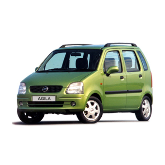
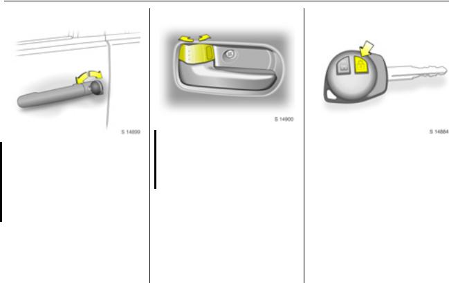
To unlock and open the vehicle: Press button c on remote control 3 or unlock with the key, pull door handle
Door locks 3 2-3, 5-12, keys 3 2-1, immobiliser 3 2-7, radio remote control 3 2-1, central locking system 3 2-3, anti-theft locking system 3 2-6.
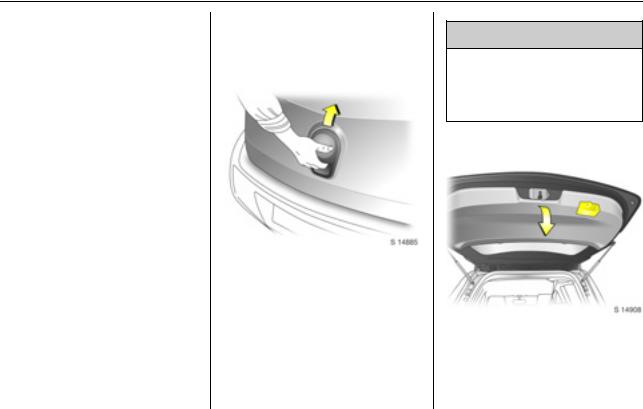
To unlock and open the tailgate: Press button c on remote control 3 or unlock with the key, operate button below the handle
Tailgate 3 2-5, radio remote control 3 2-1, central locking system 3 2-3.
Back to overview
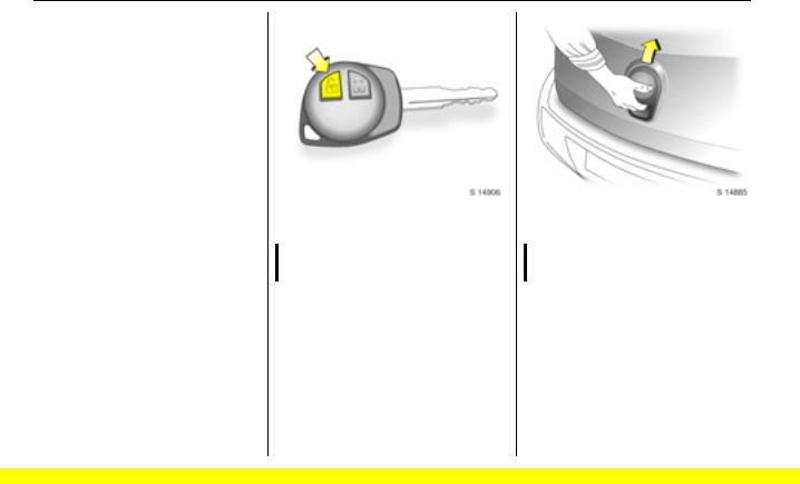
Longitudinal seat adjustment: Pull handle, slide seat, release handle
Seats 3 3-2.
Reclining seatbacks: Raise release lever
Move seatback to suit seating position.
Do not lean on seatback whilst adjusting it.
Seats 3 3-2.
Adjusting seat height 3: Raise or lower lever
Lever pumping action
|
Upwards: |
Raises seat |
|
Downwards: |
Lowers seat |
|
Seats 3 3-2. |
Back to overview
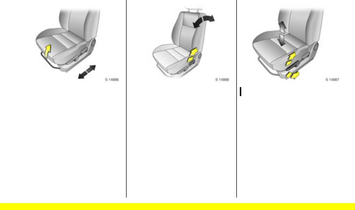
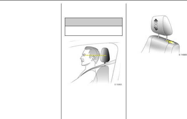
Adjusting head restraint height: Press catch, adjust height, then release
Head restraints 3 3-1.
Fitting seat belt: Pull belt out evenly from retractor, guide over shoulder and engage in buckle
The seat belt must not be twisted at any point. The lap belt must lie snugly against the body.
The seatbacks must not be tilted back too far (recommended maximum tilting angle approx. 25°).
To release seat belt, press red button on belt buckle.
Seat belts 3 3-5 to 3-8, airbag system 3 3-13, seat position 3 3-2.
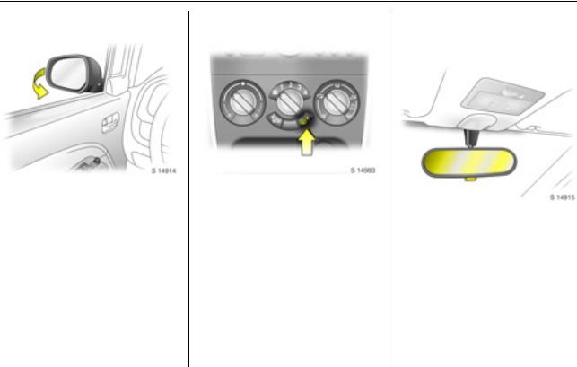
To adjust interior mirror: Swivel mirror housing
Swivel lever on underside of mirror housing to reduce dazzle at night.
Take care when driving with interior mirror adjusted for night vision. Rear view may be slightly distorted in this position.
Further information 3 2-9.
Back to overview
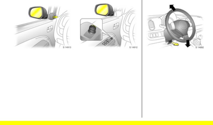
|
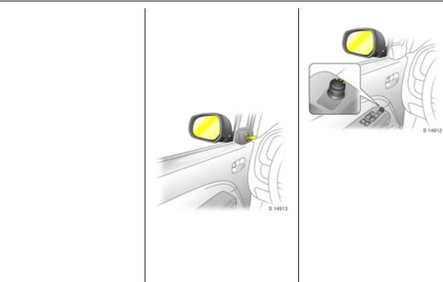
Adjusting manual exterior |
Adjusting power exterior |
|
mirrors: Swivel lever in |
mirrors 3: Four-way switch |
|
required direction |
in driver’s door |
|
Exterior mirrors 3 2-8, heated exterior |
Select corresponding mirror and |
|
mirrors 3 2-9, 8-5. |
adjust. |
|
Exterior mirrors 3 2-8, heated exterior |
|
|
mirrors 3 2-9, 8-5. |
|
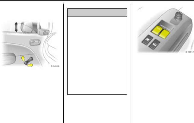
To adjust steering wheel 3: Pull lever forwards, adjust height, push lever back and engage
Adjust steering wheel only with vehicle stationary and steering column lock released.
Airbag system 3 3-13, further information 3 5-1.
Back to overview

Back to overview
![]()
|
1 |
Side air vents ……………….. |
3 8-5 |
|
|
2 |
Door window defroster |
||
|
vents …………………………… |
3 8-5 |
||
|
3 |
Steering wheel mounted |
||
|
remote control 3 …………… |
3 7-2 |
||
|
4 |
Parking lamps ………………. |
3 6-1 |
|
|
Turn signal lamps………….. |
3 6-2 |
||
|
High beam……………………. |
3 6-2 |
||
|
Dipped beam………………… |
3 6-2 |
||
|
Headlamp flash …………….. |
3 6-2 |
||
|
Rear fog lamp ………………. |
3 6-3 |
||
|
5 |
Central information display |
||
|
for time and outside |
|||
|
temperature ………….. |
3 5-3, 5-4 |
||
|
Instrument cluster …………. |
3 5-8 |
||
|
Speedometer ……………….. |
3 5-5 |
||
|
Odometer ……………………. |
3 5-6 |
||
|
Fuel gauge …………………… |
3 5-7 |
||
|
Service interval display 3 3 5-14 |
|||
|
Transmission display 3….. |
3 5-7 |
||
|
Trip computer 3………….. |
3 5-14 |
|
6 Driver’s airbag …………….. |
3 3-13 |
|
Horn ……………………………. |
3 5-2 |
7Windscreen wiper/washer . 3 5-2 Rear window wiper/washer 3 5-3
|
8 |
Tachometer ………………….. |
3 5-6 |
|
9 |
Centre air vents…………….. |
3 8-4 |
|
10 |
Hazard warning …………….. |
3 6-2 |
|
Control indicator for |
||
|
front passenger airbag |
3 3-18 |
|
|
deactivation 3 …………….. |
||
|
11 |
Upper tray ……………………. |
3 4-2 |
|
12 |
Infotainment system ………. |
3 7-1 |
|
13 |
Front passenger’s airbag |
3 3-13 |
|
14 |
Storage tray………………….. |
3 4-2 |
|
15 |
Passenger airbag deactivation |
|
|
switch 3……………………… |
3 3-17 |
|
|
16 |
Glove box …………………….. |
3 4-1 |
|
17 |
Climate controls ……………. |
3 8-1 |
|
18 |
Power outlet …………………. |
3 5-4 |
|
Cigarette lighter 3…………. |
3 5-5 |
|
19 |
Gearshift lever……….. |
3 9-4, 9-6 |
|
20 |
Storage tray |
|
|
21 |
Ignition switch………………. |
3 9-1 |
|
22 |
Steering wheel adjustment 3 5-1 |
|
|
23 |
Fuse box …………………. |
3 10-12 |
|
24 |
Bonnet release …………… |
3 10-2 |
|
25 |
Front fog lamps 3…………. |
3 6-3 |
|
Headlamp range |
||
|
adjustment 3……………….. |
3 6-1 |
|
|
TCSS deactivation 3 |
3 9-11 |
|
Back to overview
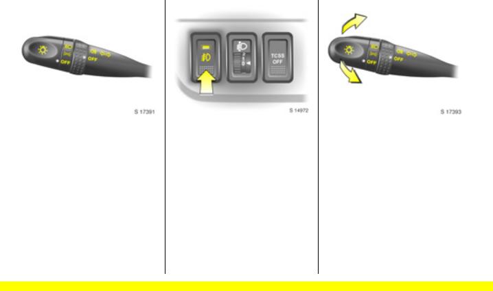
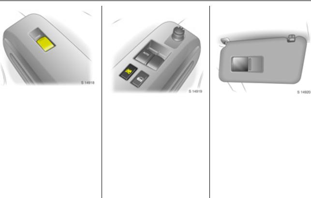
Exterior lamps controls:
Turn light switch:
P= Dipped beam or high beam
|
8 |
= |
Parking lamps |
|
|
OFF |
= |
Off |
|
|
Turn adjustment band: |
|||
|
r |
= |
Rear fog lamp |
|
|
OFF |
= |
Off |
Press button:
>= Front fog lamps 3
Headlamp warning device 3 5-13, further information 3 6-1, headlamp range adjustment 3 6-1, fog lamps 3 6-3, headlamps when driving abroad 3 6-3.
Headlamp flash, high beam and dipped beam:
|
Headlamp |
= |
Pull lever |
|
flash |
towards steering |
|
|
wheel |
||
|
High beam |
= Push lever |
|
|
forwards |
||
|
Dipped beam |
= |
Pull lever back |
|
towards steering |
||
|
wheel |
Further information 3 6-2.
Back to overview

|
In brief |
1-8 |
||
|
Turn signal lamps: |
Hazard warning lamps: |
Horn: Press j |
||||
|
Upwards |
= |
Right turn |
On |
= |
Press ¨ |
Airbag system 3 3-13, remote control |
|
Downwards |
= |
Left turn |
Off |
= |
Press ¨ again |
on steering wheel 3 3 5-1, 7-2. |
|
Further information 3 6-2. |
Back to overview

Windscreen wipers:
|
MIST |
= |
Misting function |
|
OFF |
= |
Off |
|
INT |
= Timed interval wipe 3 |
|
|
LO |
= |
Slow |
|
HI |
= |
Fast |
Move lever up from position OFF: Single swipe.
Windscreen wipers 3 5-2, further information 3 10-5, 10-30, 10-31.
Windscreen washer system: Pull lever towards steering wheel
Windscreen washer system 3 5-3, further information 3 10-5, 10-30, 10-31.
Rear window wiper and washer systems: Rotate end of lever
|
f |
= |
Washer |
|
ON |
= |
Wiper on |
|
INT |
= Timed interval wipe 3 |
|
|
OFF |
= |
Wiper off |
|
f |
= |
Washer |
Rear window wiper/washer systems 3 5-3, further information 3 10-5, 1030, 10-31.
Back to overview

Parking the vehicle:
Apply the parking brake firmly without actuating the release button. On a downhill or uphill slope, apply as firmly as possible. Depress foot brake at the same time to reduce operating forces.
Push key into ignition switch before turning to LOCK position and removing (vehicles with automatic transmission 3: depress foot brake and shift into P). Turn steering wheel until lock is felt to engage (anti-theft protection).
If the vehicle is parked on a level surface or a hill, select 1st gear before switching the ignition off, (vehicles with automatic transmission 3: shift into P). Also turn front wheels away from kerb if parked on an uphill slope.
If the vehicle is parked on a downhill slope, select reverse gear before switching the ignition off, (vehicles with automatic transmission 3: shift into P). Also turn front wheels towards kerb.
Lock doors and tailgate by pressing button e on the radio remote control 3. Press button e twice within 3 seconds to activate the anti-theft locking system 3.
Advice when parking:
Do not park the vehicle on an easily ignitable surface. The high temperature of the exhaust system could ignite the surface.
Close the windows.
The engine cooling fans may run after the engine has been switched off 3 10-1.
Radio remote control 3 3 2-1, central locking system 3 2-3.
Back to overview

2-1 Keys, doors and windows
Keys, doors and windows
|
Keys and locks ………………… |
2-1 |
|
Doors……………………………… |
2-5 |
|
Vehicle security ……………….. |
2-6 |
|
Exterior mirrors………………… |
2-8 |
|
Interior mirror…………………… |
2-9 |
|
Windows…………………………. |
2-10 |
Keys and locks
Keys
The key number is specified on the keys or on a key number tag 3. Remove key number tag from keys and make a note of the number.
The key is a constituent of the immobiliser 3. In case of loss, replacement keys can be ordered from your Opel Service Partner by quoting the key number.
Ordering keys from an Opel Service Partner guarantees problem-free operation of the immobiliser 3.
Keep spare key in a safe place. Locks 3 10-30.
Radio remote control 3
The remote control is used to operate:
Central locking system,
Anti-theft locking system 3.
The remote control has a range of approx. 5 metres. The range may be reduced due to environmental conditions or shadowing and reflection of the radio waves.
Treat the remote control unit with care: it should be protected against moisture, kept out of direct sunlight and should not be operated unnecessarily.
Back to overview

|
Keys, doors and windows |
2-2 |
Fault
If the central locking system cannot be operated with the remote control, this may be due to the following reasons:
The remote control is out of range.
The battery voltage of the remote control is too low. Change the battery in the remote control unit.
Interference from higher power radio waves from other sources.
Lock or unlock the doors manually using the key or central locking switch 3 2-3, 2-4.
Seek the assistance of a workshop to rectify the cause of the fault.
Changing battery in remote control unit
Replace the battery (CR 1620 or equivalent) in accordance with the chapter “Service and maintenance” 3 11-2 or when the range of the remote control starts to become reduced.
Remove screw on key cover and remove the transmitter.
Prise apart both halves of transmitter with a suitable screwdriver.
Replace battery, ensuring the new battery is installed correctly with positive (+) side facing the positive
(+) terminal.
Reattach both halves of transmitter and reinstall in holder, ensuring it engages correctly.
Replace cover and tighten screw.
Battery disposal
Batteries are not to be treated as household waste. They should be disposed of at a designated collection point for recycling.
Back to overview
2-3 Keys, doors and windows
Door locks
The front doors may be manually locked and unlocked using the key.
On vehicles with central locking system 3, the entire vehicle can be unlocked by turning the key twice in the driver’s door lock.
The tailgate is unlocked when the driver’s door is opened.
To lock or unlock doors from inside the vehicle, press the interior lock.
To lock front doors from outside the vehicle, press the interior lock and keep exterior door handle raised when closing the door.
Central locking system 3
For front doors, rear doors and tailgate.
To lock:
Press button e on remote control:Hazard warning lamps flash once.
All doors and the tailgate are locked.
Always ensure that the doors, bonnet, tailgate and windows are properly closed before locking the vehicle.
Back to overview
|
Keys, doors and windows |
2-4 |
To unlock driver’s door only: Press button c on remote control once:
Hazard warning lamps flash twice.
To unlock entire vehicle:
Press button c on remote control twice:
Hazard warning lamps flash twice with each press.
If no door is opened within approx. 30 seconds after the vehicle has been unlocked via the remote control, the vehicle is relocked automatically.
9 Warning
For safety reasons, the vehicle cannot be locked or unlocked via the remote control if the key is in the ignition switch.
The vehicle can also be manually locked and unlocked by turning the key in the driver’s door lock.
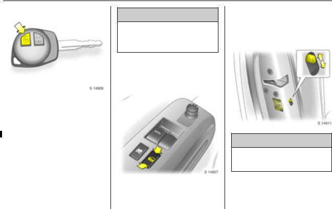
Central locking switch m
Use the central locking switch to lock or unlock the doors and tailgate from inside the vehicle.
Press the front part of the switch to lock or the rear part of the switch to unlock all doors and tailgate.
Safety locks
9 Warning
Use the safety locks whenever children are occupying the rear seats.
To engage lock, open door and move lock lever to lower position. Door cannot then be opened from inside.
Back to overview
2-5 Keys, doors and windows
To disengage safety lock, raise lock lever.
Lockout protection
To prevent the driver from being inadvertently locked out, the driver’s door cannot be locked when it is open.
Doors
Tailgate
To open
The tailgate can be opened by operating the button below the handle and lifting the tailgate.
If the tailgate is open when the ignition is switched on, control indicator 9 illuminates in the instrument cluster.
9 Warning
Do not drive with tailgate open or ajar, e.g. when transporting bulky objects, since toxic exhaust gases could penetrate the vehicle interior.
To close
There is a handle on the inside of the tailgate for closing the luggage compartment.
Back to overview
![]()
|
Keys, doors and windows |
2-6 |
Close tailgate by pushing it down so it latches securely. Ensure tailgate is fully closed before driving.
Emergency tailgate release
If the central locking system 3cannot be operated with the remote control, the tailgate can be opened from inside the vehicle.
Fold rear seats forward to allow access to the tailgate (3 3-3) and push up on emergency lever using a suitable screwdriver to open the tailgate.
Vehicle security
Anti-theft locking system 3
9 Warning
Do not use the system if there are people in the vehicle. The doors cannot be unlocked from inside.
All doors are secured against opening and must be unlocked with the vehicle key. Unlocking is not possible in any other way, so keep spare key in a safe place.
To lock:
All doors and the tailgate must be closed.
Press button e on remote control twice within 3 seconds:
Hazard warning lamps flash twice. — or —
Turn key in driver’s door lock towards rear of vehicle twice within
3 seconds.
Interior locks on all doors are positioned such that doors cannot be opened.
To unlock:
Back to overview

2-7 Keys, doors and windows
To unlock driver’s door only: Press  button c on remote control:
Hazard warning lamps flash twice. — or —
Turn key in driver’s door lock towards front of vehicle once.
To unlock entire vehicle: Press button c on remote control twice:
Hazard warning lamps flash twice with each press.
— or —
Turn key in driver’s door lock towards front of vehicle twice.
Immobiliser 3
The system checks whether the vehicle may be started using the key that has been inserted. If the key is recognised as «authorised», the vehicle can be started. The check is carried out via a transponder housed in the key.
The immobiliser is automatically activated when the key is turned to the LOCK position and removed from the ignition switch.
The theft-deterrent control indicator starts flashing after the key is turned to positions LOCK or ACC, or removed from the ignition switch.
Fault
If control indicator o or A flashes after the ignition is switched on, there may be a fault in the immobiliser system. If the engine cannot be started:
Turn key to LOCK position and remove,
wait approx. 2 seconds,
then repeat starting procedure.
Back to overview
|
Keys, doors and windows |
2-8 |
If the control indicator fails to extinguish, try to start the engine using the spare key and seek the assistance of a workshop to rectify the cause of the fault.
Note
The immobiliser does not lock the doors. Therefore, after leaving the vehicle, always lock it 3 2-3.
Exterior mirrors
Convex mirrors
As exterior mirrors are convex, objects are closer than they appear. Use interior mirror to judge size and distance of objects.
Manual mirrors
Adjust mirrors by swivelling lever in required direction.
Power mirrors 3
Adjust with the four-way switch in driver’s door: Turn selector switch to left or right; four-way outer part of switch adjusts corresponding mirror.
The mirror glass swivels in the same direction as the activation of the fourway switch.
Return the selector switch to the central position to prohibit further adjustment.
Back to overview
2-9 Keys, doors and windows
Folding mirrors
For the safety of pedestrians, the exterior mirrors will swing out of their normal mounting position in the event of an accident-like impact.
Reposition the mirror by applying slight pressure to the mirror housing.
Heated mirrors 3
The heating operates in conjunction with the heated rear window using button Ü.
Heated rear window, heated exterior mirrors 3 8-5.
Interior mirror
Manual mirror
To adjust interior mirror, swivel mirror housing.
Swivel lever on underside of mirror housing to reduce dazzle at night.
Take care when driving with interior mirror adjusted for night vision. Rear view may be slightly distorted in this position.
Back to overview
|
Keys, doors and windows |
2-10 |
Windows
Manual windows
The door windows can be operated with the crank.
Power windows 3
9 Warning
Care must be taken when operating the power windows. There is a risk of injury, particularly for children, and a danger that articles could become trapped.
If there are children on the front passenger’s seat, press the z switch in the driver’s door to deactivate power window operation.
Keep a close watch on the windows when closing them. Ensure that nothing becomes trapped in them as they move.
Before leaving the vehicle, remove the ignition key in order to prevent unauthorized operation.
Operational with key in ignition switch position ON.
Driver’s and front passenger’s door windows are operated via two switches located in the driver’s door.
For incremental operation, briefly pull or press the appropriate switch.
For automatic opening of the driver’s door window, press the switch down fully and release it. Pull up the switch to stop the window movement.
Back to overview
2-11 Keys, doors and windows
An additional switch is located in the front passenger’s door.
In the event of difficulty due to frost or the like, pull the relevant window switch several times until the window is closed.
Child safety system
Press the z switch in driver’s door to deactivate front passenger’s door power window operation when a child is occupying the seat.
Press switch again to activate power window operation.
Sun visors
Use the sun visor to protect from glare by pulling it up, down or swivelling it to the side.
Depending on equipment version, sun visors also have vanity mirrors 3.
Back to overview
|
Seats, restraints and interior |
3-1 |
Seats, restraints and interior
|
Head restraints ………………… |
3-1 |
|
Front seats………………………. |
3-2 |
|
Rear seats ………………………. |
3-3 |
|
Seat belts………………………… |
3-5 |
|
Child restraints…………………. |
3-9 |
|
Airbag system ………………….. |
3-13 |
Head restraints
Head restraint position
9 Warning
Only drive with head restraints correctly adjusted.
For maximum protection, the middle of the head restraint should be at eye level. If this is not possible for extremely tall persons, set to highest position, and set to lowest position for extremely small persons.
Height adjustment
To adjust head restraint height, press catch, adjust height to suit then release the catch.
Removal
Press catch. Pull up and remove the head restraint.
Stow head restraints securely in luggage compartment.
Back to overview

3-2 Seats, restraints and interior
Front seats
Seat position
9 Warning
Only drive with the seats correctly adjusted.
Adjust driver’s seat such that, with the driver sitting upright, the steering wheel is held in the area of its upper spokes with the driver’s arms slightly bent.
Slide front passenger’s seat as far back as it will go.
The seatbacks must not be tilted back too far (recommended maximum tilting angle approx. 25°).
Longitudinal seat adjustment
9 Warning
Never adjust seats whilst driving, as they could move uncontrollably.
To adjust, pull the handle on the front seat, slide the seat and release the handle.
Ensure seat audibly latches into position before driving.
Reclining seatbacks
To adjust, raise the release lever, move seatback to suit seating position and release lever to lock seatback in position.
Do not lean on the seatback whilst adjusting it.
Back to overview
|
Seats, restraints and interior |
3-3 |
Adjusting seat height 3
To adjust, operate lever on side of seat.
Lever pumping action Upwards: Raises seat Downwards: Lowers seat
Rear seats
Folding rear seatbacks
9 Warning
When adjusting the rear seatbacks, use caution; beware of moving parts.
The luggage compartment can be enlarged by folding the rear seatbacks onto the seat cushions.
Ensure front seats are not in reclined position and push rear seat head restraints all the way down.
When folding the rear seatbacks, ensure the seat belts are unbuckled.
Route outboard rear seat belts, including the latch plates, through their respective belt holders (as illustrated), ensuring they are not twisted at any point.
Back to overview
3-4 Seats, restraints and interior
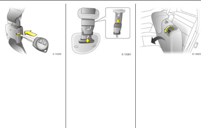
Unlatch detachable connector on centre rear seat belt by inserting the ignition key in the slot on the connector and allow the belt to retract.
Insert latch plate into the slit on the belt webbing and insert detached connector latch plate in roof holder slot to the rear of the belt webbing.
To fold outboard rear seatbacks separately 3, pull seatback release lever downwards, fold seatback forwards and down onto seat cushion.
Back to overview
![]()
|
Seats, restraints and interior |
3-5 |
To fold rear bench seat 3, pull both outboard seatback release levers downwards simultaneously, fold seatback forwards and down onto seat cushion.
Do not allow passengers to sit on folded seatbacks, or place any unrestrained loads on them.
Restoring rear seatbacks
Raise seatback and push back to its original position. Ensure seatback latches into place by pushing top of seatback and pulling it forwards again.
Pull detached connector latch plate of centre rear seat belt from roof holder slot and insert in connector, with the arrows aligned. Ensure the latch plate and connector audibly engage.
Release outboard rear seat belts from their respective belt holders.
Seat belts
Three-point seat belt
The front and rear seats are equipped with three-point seat belts with automatic retractors and locking devices, allowing freedom of body movement when the vehicle moves at a constant speed, although the spring-tensioned belts are always a snug fit.
The belt has a “vehicle sensitive retractor” which is designed to lock during heavy acceleration or deceleration in any direction.
Back to overview

3-6 Seats, restraints and interior
9 Warning
Always wear your seat belt, also in urban traffic and when you are a rear seat passenger. It can save your life!
In the event of an accident, persons not wearing seat belts endanger their fellow occupants and themselves.
Control indicator X for driver’s seat belt reminder 3 5-9.
Seat belts are designed to be used by only one person at a time. They are only suitable for children aged up to 12 years or smaller than 150 cm if used in conjunction with a child restraint 3.
Belt force limiters
Load limiters on the front seats reduce the impact on the seat occupant’s body from a tensioning belt, in the event of frontal collisions or rear impacts of a certain severity. The belt force is controlled, to reduce the risk of belt-inflicted injury.
Belt tensioners
The seat belt systems on the front seats incorporate belt tensioners housed in the belt buckles and seat belt retractors.
In the event of frontal collisions or rear impacts of a certain severity, belt buckles and seat belt retractors tighten the seat belts; the shoulder and lap belts are instantaneously tightened to fit the occupant’s body more snugly.
9 Warning
Improper handling (e.g. removal or installation) can activate the belt tensioners.
The belt tensioners actuate only once and must be replaced after activation. Seek the assistance of a workshop.
The belt tensioners only actuate once, indicated by continuous illumination of control indicator vin the instrument cluster 3 5-9. Deployed belt tensioners must be replaced. Seek the assistance of a workshop.
Accessories not released for your vehicle type and other objects must not be fixed or placed within the action zone of the belt tensioners, as they may result in injury if the belt tensioners are triggered.
Back to overview

|
Seats, restraints and interior |
3-7 |
How to wear seat belts properly
Pull the belt out evenly from the retractor and guide it over the shoulder, making certain that it is not twisted at any point. The belt must not rest against your neck or arm.
The seatback must not be tilted back too far (the recommended maximum tilting angle is approx. 25°).
Insert the latch plate into the buckle.
Seat belt buckles are designed such that latch plates cannot be inserted in
 the incorrect buckle.
The lap belt must not be twisted and must fit snugly across the body. Tension the belt frequently whilst driving by tugging the diagonal part of the belt.
The centre rear seat belt position has a twin buckle arrangement. Engage the smaller latch plate (1) into the correct buckle, then pull the belt across and audibly engage into the buckle marked CENTER (2).
9 Warning
The belt must not rest against hard or fragile objects in the pockets of your clothing. Do not place any objects (e.g. handbags) between the belt and your body.
Control indicator X for driver’s seat belt reminder 3 5-9.
Back to overview

3-8 Seats, restraints and interior
Seat belt height adjustment
Height adjustment of front seat belt upper anchorage points.
Do not adjust height whilst driving.
Pull out lock knob and slide adjuster up or down to desired position.
Ensure sliding height adjuster latches into position.
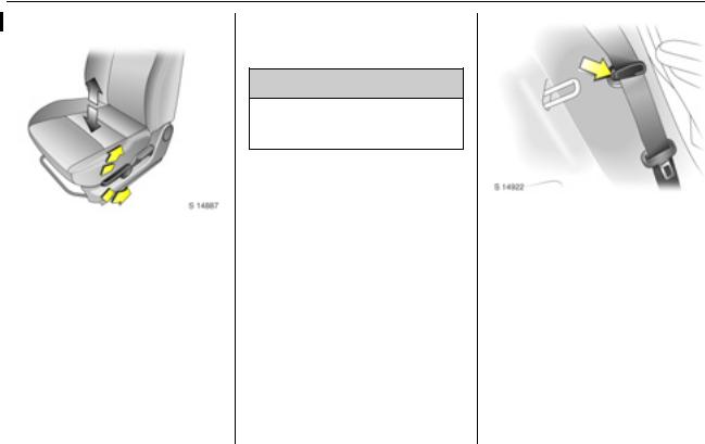
Removing the belt
To remove the belt, press the red release button on the belt buckle; the belt will retract automatically.
Guide the belt as it retracts, to prevent personal injury and damage  to interior surfaces.
Seat belt use during pregnancy
9 Warning
On pregnant women in particular, the lap belt must be positioned as low as possible across the pelvis in order to prevent pressure on the abdomen.
Seat belt care
Periodically inspect all parts of the belt system for damage and to make sure they are functioning properly.
Have damaged parts replaced. After an accident, belts and triggered belt tensioners must be replaced by new ones.
Do not perform any alterations on the belts, their anchorages, the automatic retractors or the belt buckles.
Make sure that belts are not damaged or trapped by sharp-edged  objects.
Back to overview

|
Seats, restraints and interior |
3-9 |
Child restraints
Child restraint systems 3
When a child restraint system is being used, pay attention to the following usage and installation instructions and also those supplied with the child restraint system.
The country in which you are driving could require the use of child restraint systems at specific seats. Follow all local and national regulations.
9 Warning
When using a child restraint system on the front passenger’s seat, the airbag systems for the front passenger’s seat must be deactivated; if not, the triggering of the airbags poses a risk of fatal injury to the child.
This is especially the case if rearfacing child restraint systems are used on the front passenger’s seat.
Selecting the right system
Your child should be transported facing rearwards in the vehicle for as long as possible. It is appropriate to change the system when the child’s head can no longer be properly supported at eye height. The child’s cervical vertebrae are still very weak and in an accident they suffer less stress in the semi-prone rearward position than when sitting upright.
Children under 12 years or under 150 cm tall should only travel in an appropriate child safety seat.
Never carry a child whilst travelling in the vehicle. The child will become too heavy to hold in the event of a collision.
When transporting children, use a child restraint system that is suitable for the child’s weight, age and height.
Ensure that the child restraint system to be installed is compatible with the vehicle type.
Ensure that the mounting location of the child restraint system within the vehicle is correct.
Only allow children to enter and exit the vehicle at the side facing away from the traffic.
When the child restraint system is not in use, secure the seat with a seat belt or remove it from the vehicle.
A child restraint system which has been subjected to stress in an accident must be replaced.
Opel produce a range of child restraint systems. We recommend
you consult an Opel Service Partner.
Back to overview

|
3-10 |
Seats, restraints and interior |
||||||||||
|
Child restraint installation locations |
|||||||||||
|
Mass group |
Front passenger’s seat |
Outboard rear |
Centre rear seat |
||||||||
|
airbags |
airbags |
seats |
|||||||||
|
activated |
deactivated |
||||||||||
|
Group 0: up to 10 kg |
U1) |
U2) |
|||||||||
|
or approx. 10 months |
X |
X |
|||||||||
|
Group 0+: up to 13 kg |
U1) |
U2) |
|||||||||
|
or approx. 18 months |
X |
X |
|||||||||
|
Group I: 9 to 18 kg |
U1) |
U2) |
|||||||||
|
or approx. 1 to 4 years |
X |
X |
|||||||||
|
Group II: 15 to 25 kg |
|||||||||||
|
or approx. 3 to 7 years |
X |
X |
U |
X |
|||||||
|
Group III: 22 to 36 kg |
|||||||||||
|
or approx. 6 to 12 years |
X |
X |
U |
X |
1)Only if front passenger’s seat airbag systems are deactivated 3 3 3-17. Seat height 3 must be in its uppermost position 3 3-3.
Group 0 and 0+: Front passenger’s seat must be in its rearmost position 3 3-2.
Group I: When attaching child restraints by means of three-point seat belts, seat belt must run forwards from the anchorage point 3 3-8.
2)Seat location with ISOFIX mountings available 3 3-11.
X = Seat position not suitable for children in this mass group.
U = Suitable for ’universal’ category child restraints, attached with the vehicle seat belt, approved for use in this mass group.
Back to overview

|
Seats, restraints and interior |
3-11 |
ISOFIX child restraint systems 3
Lower ISOFIX mountings
The ISOFIX mountings located between the seatback and seat cushion are used for mounting ISOFIX child restraint systems on the outboard rear seats.
The instructions accompanying the ISOFIX child restraint system are to be expressly followed.
Only ISOFIX child restraint systems approved for the vehicle may be used.
Top-Tether child restraint mountings
The Top-Tether mountings located on the rear of the seatbacks are designed to hold child restraints which come equipped with a toptether mounting strap only.
Please be sure to follow the instructions provided with the child restraint system.
ISOFIX child restraint classes
The ISOFIX size class is shown on a label attached to the child restraint system.
A = Forward-facing child restraint for children of maximum size in the weight class 9 to 18 kg.
B = Forward-facing child restraint for smaller children in the weight class 9 to
18 kg.
B1 = Forward-facing child restraint for smaller children in the weight class 9 to
18 kg.
C = Rear-facing child restraint for children of maximum size in the weight class up to 13 kg.
D = Rear-facing child restraint for smaller children in the weight class up to 13 kg.
E = Rear-facing child restraint for young children in the weight class up to 13 kg.
Back to overview
|
3-12 |
Seats, restraints and interior |
|||||
|
Permissible options for fitting an ISOFIX child restraint system |
||||||
|
Mass group |
ISOFIX size |
Fixture |
Front |
Outboard rear |
Centre rear |
|
|
class |
passenger’s seat |
seats |
seat |
|||
|
Group 0: up to 10 kg |
||||||
|
or approx. 10 months |
E |
ISO/R1 |
— |
IL |
— |
|
|
Group 0+: up to 13 kg |
||||||
|
or approx. 18 months |
E |
ISO/R1 |
— |
IL |
— |
|
|
D |
ISO/R2 |
— |
IL |
— |
||
|
C |
ISO/R3 |
— |
IL |
— |
||
|
Group I: 9 to 18 kg |
||||||
|
or approx. 1 to 4 years |
D |
ISO/R2 |
— |
IL |
— |
|
|
C |
ISO/R3 |
— |
IL |
— |
||
|
B |
ISO/F2 |
— |
IL, IUF1) |
— |
||
|
B1 |
ISO/F2X |
— |
IL, IUF2) |
— |
||
|
A |
ISO/F3 |
— |
IL, IUF1) |
— |
1)Head restraint must be in its uppermost locking position or removed and stowed securely in luggage compartment.
2)Head restraint must be removed and stowed securely in luggage compartment.
IL = Suitable for particular ISOFIX restraint systems of the ‘specific-vehicle’, ‘restricted’ or ‘semi-universal’ categories. The ISOFIX restraint system must be approved for the specific vehicle type.
IUF = Suitable for ISOFIX forward-facing child restraint systems of universal category approved for use in this mass group. — = No ISOFIX mounting locations available at this location.
Back to overview

|
Seats, restraints and interior |
3-13 |
Airbag system
The airbag system consists of several individual systems.
When triggered, the driver’s and front passenger’s airbags inflate to form safety cushions for the driver and front passenger.
When triggered, the side airbag inflates to form a safety cushion for the driver and/or front passenger in the respective door area.
When triggered, the curtain airbag inflates to provide a safety barrier in the head area on the respective side of the vehicle.
No impairment of view will occur, as airbags inflate and deflate so quickly that they are often not noticed in an accident.
9 Warning
The systems can be triggered abruptly and cause injury if they are handled improperly.
The airbag system and belt tensioner control electronics can be found in the centre console area. In order to avoid malfunctions, do not store magnetic objects in this area.
Do not stick or place anything on the steering wheel, instrument panel, front seatbacks in the vicinity of the airbags and seat areas or cover them with other materials.
Each airbag can be triggered only once. Once triggered, an airbag must be replaced immediately. Seek the assistance of a workshop.
Do not perform any modifications to the components of the airbag system, as this will render the vehicle unroadworthy.
We recommend having the steering wheel, the instrument panel, all panelling parts, the door seals, handles and the front seats removed by a workshop.
Control indicator for airbag systems 3 5-9.
Front airbag system
The front airbag system is identified by the words AIRBAG and SRS AIRBAG on the steering wheel and above the glove box respectively.
Back to overview

3-14 Seats, restraints and interior
The front airbag system will be triggered depending on the severity of the accident, and within the range shown in the illustration.
The ignition must be switched on.
When triggered, the airbags inflate in milliseconds. Forward movement of the driver and front passenger is checked and the risk of injuries to the upper body and head are thereby substantially reduced.
9 Warning
The front airbag system provides optimum protection when the seat, seat belt, seatback and head restraint are correctly adjusted as described 3 3-1 to 3-5.
Do not place objects, children or pets in the area in which the airbags inflate.
Back to overview
![]()
|
Seats, restraints and interior |
3-15 |
9 Warning
The three-point seat belt must always be correctly fitted 3 3-5. The front airbag system serves to supplement the three-point seat belts.
Side airbag system 3
The side airbags are identified by the words SRS AIRBAG on the outboard side of the front seatbacks and on the B-pillar.
The side airbag system will be triggered depending on the severity of the accident and within the range shown in the illustration.
The ignition must be switched on.
Back to overview

3-16 Seats, restraints and interior
Curtain airbag system 3
|
When triggered, the airbags inflate in |
The curtain airbag system will be |
||
|
milliseconds. The risk of injury to the |
The curtain airbag system is |
triggered depending on the severity |
|
|
upper body and pelvis in the event of |
of the accident and within the range |
||
|
identified by the words SRS AIRBAG |
|||
|
a side impact is thereby substantially |
shown in the illustration. |
||
|
on the roof frame. |
|||
|
reduced. |
The ignition must be switched on. |
||
9 Warning
Do not place objects or parts of your body in the area in which the airbag inflates.
Note
Only install seat covers to the front seats that have been approved for your vehicle with side airbags.
Back to overview

|
Seats, restraints and interior |
3-17 |
When triggered, the airbags inflate in milliseconds. The risk of injury to the head in the event of a side impact is substantially reduced.
9 Warning
Do not place any objects between the airbag systems and the vehicle occupants.
Only use hooks on the handles in the roof to hang light articles of clothing or coat hangers. Do not place objects in the pockets of the hanging items.
Passenger airbag deactivation switch 3
The front and side airbags for the front passenger’s seat must be deactivated if a child restraint system 3 is to be fitted on the front passenger’s seat. The curtain airbag system 3, the belt tensioners and all driver’s airbag systems remain active when the front passenger’s airbag systems are deactivated. The front passenger’s airbag systems are active in the as-delivered condition.
The deactivation switch is located on the side of the instrument panel on the front passenger’s side of the vehicle.
Control indicator * illuminates in the instrument panel when the front and side airbag systems for the front passenger’s seat have been deactivated.
The setting selected remains stored when the ignition is switched on.
Deactivation
With the vehicle stationary and the ignition switched off:
Insert ignition key in airbag deactivation switch and turn to the OFF position.
Back to overview

3-18 Seats, restraints and interior
Switch on ignition; control indicator * flashes in the instrument panel then remains illuminated, to display the current status.
Airbag systems for the front passenger’s seat are deactivated.
Activation
The airbag systems for the front passenger’s seat must be activated when the child restraint system has been removed and the seat is occupied.
Activate the airbag systems with the vehicle stationary and the ignition switched off:
Insert ignition key in airbag deactivation switch and turn to the ON position.
Switch on ignition; control indicator * flashes in the instrument panel then extinguishes, to display the current status.
Airbag systems for the front passenger’s seat are reactivated.
Back to overview

Storage compartments
|
Interior stowage ……………….. |
4-1 |
|
Luggage compartment………. |
4-3 |
|
Roof rack system 3 …………… |
4-6 |
Interior stowage
Glove box
To open, pull handle.
To close, push lid until it latches into position.
Cup holders
Located in the front and rear of the centre console between the front seats.
Back to overview

4-2 Storage compartments
Instrument panel storage
|
The front and rear cup holders are a |
The front passenger’s tray is located |
|
|
fixed size. |
The instrument panel upper tray is |
above the glove box, for storing |
|
maps, newspapers etc. |
||
|
located above the centre air vents. |
||
|
To open, lift front edge of lid. |
||
|
To close, push lid down until it latches |
||
|
into position. |
9 Warning
Do not place glasses, CDs, CD cases or flammable items, e.g. cigarette lighter, in the instrument panel upper tray when parked in direct sunlight or in hot weather, as the tray can become very hot.
Back to overview
 Loading…
Снова всех приветствуем на страницах нашего бортжурнала!Есть у меня привычка- собирать литературу техническую, по автомобилю, что я владею)А ещё есть привычка делиться найденным с людьми, которые не так опытны в поисках на интернетных просторах!)
Итак Вашему вниманию представляется всё, что я пока нарыл на наших Агил и брата Вагона)
Suzuki Wagon R+ / Opel Agila : руководства по ремонту и обслуживанию
Описание: Сервисная документация на Wagon R+ / Opel Agila
(90% — на пострестайлинговые венгерские Wagon R+ (RB413), русское руководство по ремонту — также для Opel Agila, некоторые вещи для старого Wagon).
Инфомация внутри:
— Wagon_K10A_parts_manual (doc)
Коды запчастей к Вагону K10A
— ServiceManuals\English (pdf)
Сервисные мануалы по ремонту Wagon R+ на английском (источник — Greg Snowdon, за что ему большое спасибо)
— ServiceManuals\Hungarian (pdf)
Сервисные мануалы по ремонту Wagon R+ на венгерском. Частично пересекаются с английскими,
но некоторые (например дизели) в английской версии отсутствуют
— ServiceManuals\MaintananceIntervals (pdf)
список сервисных работ ТО (для моделей RB413 и SR410) — английский
— ServiceManuals\RusRepairBook (gif)
Название книги: Suzuki Wagon R, Opel Agila: Руководство по ремонту и эксплуатации
Год выпуска:2008
Жанр: Руководства по ремонту и обслуживанию
Издательство: УП «Гуси-Лебеди»
Формат: gif
Количество страниц: 316
Качество: Сканированный текст
Описание:
Скан русской книги по ремонту Wagon R+ и Opel Agila.
Не так правильно и полно как английские руководства, но понятно.
Склеено из двух различных вариантов сканирования (но все равно несколько
страниц не хватает — список внутри).
— ServiceManuals\air_filter (jpg)
иллюстрации по замене салонного воздушного фильтра
— ServiceManuals\Ignis wiring diagram (pdf)
электрическая схема на Ignis, можно частично использовать для Вагона
— ServiceManuals\SparePartsCatalog_Wagon_R_plus (doc)
Коды запчастей к Wagon Вагону R+
— UserManual_Rus (gif)
отсканированное руководство по эксплуатации Wagon R+
disk.yandex.ru/d/qySVg5ddoGMZTg
Посмотреть инструкция для Opel Agila (2008) бесплатно. Руководство относится к категории автомобили, 2 человек(а) дали ему среднюю оценку 9. Руководство доступно на следующих языках: английский. У вас есть вопрос о Opel Agila (2008) или вам нужна помощь? Задайте свой вопрос здесь
Не можете найти ответ на свой вопрос в руководстве? Вы можете найти ответ на свой вопрос ниже, в разделе часто задаваемых вопросов о Opel Agila (2008).
Как перевести мили в километры?
1 миля равна 1,609344 километрам, а 1 километр — 0,62137119 милям.
Где я могу узнать идентификационный номер транспортного средства Opel?
Место размещения идентификационного номера транспортного средства зависит от марки и типа транспортного средства. Номер может быть выбит на раме транспортного средства или указан на номерном знаке. Чтобы узнать место расположения идентификационного номера транспортного средства лучше всего ознакомиться с руководством по эксплуатации Opel Agila (2008).
Что такое идентификационный номер транспортного средства (VIN)?
Идентификационный номер транспортного средства — уникальный для каждого транспортного средства идентификационный номер. Аббревиатура VIN расшифровывается как «Vehicle Identification Number» (Идентификационный номер транспортного средства).
Когда транспортному средству Opel требуется техническое обслуживание?
Регулярное техническое обслуживание необходимо всем транспортным средствам. С информацией о том, как часто необходимо проходить техническое обслуживание и чему именно стоит уделять особое внимание можно ознакомиться в инструкции по техническому обслуживанию. Как правило, транспортное средство требует технического обслуживания каждые 2 года или 30 000 километров пробега.
Когда следует заменять тормозную жидкость на Opel?
Тормозную жидкость рекомендуется менять каждые два года.
В чем разница между топливом E10 и E5?
В топливе E10 содержится до десяти процентов этанола, в то время как в E5 содержится менее пяти процентов. Соответственно, топливо E10 менее вредит окружающей среде.
Одна или несколько дверей не открываются изнутри. Что мне делать?
Скорее всего, замок оснащен защитой от детей и поэтому не может быть открыт изнутри. Процедура открытия замка с защитой от детей зависит от марки и типа замка.
Автомобильный радиоприемник не включается, что делать?
Если автомобильный радиоприемник не включен, на него не будет подаваться питание. Убедитесь, что красный провод подключен к контактному источнику питания, а желтый провод — к источнику питания постоянной мощности.
Инструкция Opel Agila (2008) доступно в русский?
К сожалению, у нас нет руководства для Opel Agila (2008), доступного в русский. Это руководство доступно в английский.
Не нашли свой вопрос? Задайте свой вопрос здесь
#1
![]()
Отправлено 25 Апрель 2005 — 12:39
Облазил массу форумов, и по Suzuki Wagon R+, нигде нет инструкции ни для него ни для Опель Агила.
#2
![]()
PITon
PITon
-

- Клубные пользователи
-
- Cообщений: 4 099
Гад ползучий)))

- Город:квартал Абрамцево
- Интересы:Футбол, игровые виды спорта
- Автомобиль: Meriva Cosmo 1,6 MT Star Silver, 2008; Nissan Qashqai 1,6 SV+, White, 2010
- @Упоминание
Отправлено 19 Январь 2007 — 21:03
Уважаемые Агиловоды!
Предугадывая вопросы относительно инструкции для Агилы, выкладываю здесь файл для скачивания.
Это инструкция для Suzuki Wagon R, что, собственно одно и тоже.
Кликаем
здесь
и качаем. После архив надо распаковать и наслаждаться жизнью 
P.S. Друзья! Если у Вас есть ещё какая-либо бумажная информация, просьба писать мне в личку. Спасибо.
Змей принято не любить….
#3
![]()
Aleks [VRN]
Aleks [VRN]
-
- Постоянные посетители
-
- Cообщений: 33
Начинающий Опелевод


- Город:г. Воронеж
- Интересы:Toyota Caldina
- Автомобиль: Opel Agila, 2002 г.в., Z12XE
- @Упоминание
Отправлено 26 Ноябрь 2007 — 09:08
Скачал на нашем сайте вот эти Диски
TIS 2000(2004) (полная версия, русское меню)
Установил на комп. Все на английском, в списке доступных языков — только английский,
не совсем понятен принцип работы программы — где что искать и где как смотреть — не понял.
Вроде не чайник, но то ли времени надо больше, чтобы разобраться, то ли есть какая-то специфика работы с такими программами.
Подскажите плизззз!
Opel Agila, 2002, 1.2/75
2SRS, AC, EPS
Цвет — серебристый металик
г. Воронеж
#4
![]()
sergg66
sergg66
- Город:С-Петербург (Петродворец)
- Автомобиль: Opel Agila 1.0
- @Упоминание
Отправлено 30 Ноябрь 2007 — 09:16
Цитата
‘ date=’26.11.2007, 9:08′ post=’234455’]
Скачал на нашем сайте вот эти Диски
TIS 2000(2004) (полная версия, русское меню)
Установил на комп. Все на английском, в списке доступных языков — только английский,
не совсем понятен принцип работы программы — где что искать и где как смотреть — не понял.
Вроде не чайник, но то ли времени надо больше, чтобы разобраться, то ли есть какая-то специфика работы с такими программами.
Подскажите плизззз!
Пробовал устанавливать — дествительно странно- только английский… Через день переустанавливал Винду, потом тра.. мучался еще пару дней и в результате TIS2000 больше не пробовал ставить. Самому интересен этот вопрос…
#5
![]()
аморальный
аморальный
- Город:Екатеринодаръ
- Автомобиль: OPEL AGILA 1.0 2003 г.
- @Упоминание
Отправлено 09 Июнь 2008 — 12:19
http://www.amazon.de…s…1904&sr=8-1
немогу сообразить, это просто мануал, типа вот этого http://forum.opel-cl…?showtopic=8261
или книжка по ремонту..?
думаю заказать себе.. 20 евро правда просят..
Сообщение отредактировал аморальный: 09 Июнь 2008 — 12:22
собой являя запредельность..
#6
![]()
Paruthik
Paruthik
-
- Постоянные посетители
-
- Cообщений: 87
Начинающий Опелевод
- Город:Питер
- Автомобиль: OPEL-AGILA
- @Упоминание
Отправлено 09 Июнь 2008 — 14:04
Сканируем книжку распазнаём и отпровляем в промт или в другой переводчик и более менее сностная книжка для ремонта 
#7
![]()
toolma
toolma
- Город:Казань,рег.016
- Автомобиль: НИВА 21214, Opel Corsa D 1.2,Suzuki Wagon R+ 4WD
- @Упоминание
Отправлено 16 Июнь 2008 — 13:29
По мотору подойдет косрсовская книга.
А вот по ходовке и прочему есть ремонгтный мануал по Сузуки-Игнису на www.suzuki-club.ru. Зарегиться и в поиске пошукать. Весил 4 метра, я пользуюсь.
#8
![]()
toolma
toolma
- Город:Казань,рег.016
- Автомобиль: НИВА 21214, Opel Corsa D 1.2,Suzuki Wagon R+ 4WD
- @Упоминание
Отправлено 15 Сентябрь 2008 — 08:19
#9
![]()
bananu
bananu
- Город:Москва "СТРОГИНО"
- Автомобиль: был opel agila 1.2, сейчас opel meriva 1.6
- @Упоминание
Отправлено 22 Сентябрь 2008 — 09:39
А я сегодня вот тут заказал http://www.ozon.ru/c…ail/id/4079589/ теперь жду!!!
BANANU
#10
![]()
bananu
bananu
- Город:Москва "СТРОГИНО"
- Автомобиль: был opel agila 1.2, сейчас opel meriva 1.6
- @Упоминание
Отправлено 24 Сентябрь 2008 — 21:56
Привезли мне сегодня заветную книженцию!  Если честно я очень разочаровался, примерно 85% всех описаний SUZUKI WAGON R+ по AGILA очень скудно. Описаний двигателя Z12XE вообще нет, система задних тормозов как у нас вообще нет…… Вообщем проще перечислить то, что есть:
Двигатель Z10XE и немного по кузову!!! Кинули нас бургеры с описаниями!!!  Почему бургеры, да потому, что в анотации книги написано «ПЕРЕВОД С НЕМЕЦКОГО» :-(((((((((((((((
Сообщение отредактировал bananu: 25 Сентябрь 2008 — 07:08
BANANU
#11
![]()
Dron
Dron
- Город:Оренбурга
- Автомобиль: Astra 1.6 МКПП Cosmo
- @Упоминание
Отправлено 16 Октябрь 2008 — 08:50
У сузуководов есть вот это http://www.suzuki-cl…….=file&id=57 даже не зная языка по картинкам почти все понятно ….
Он сказал «ПОЕХАЛИ» и запил водой
#12
![]()
Ralf
Ralf
-
- Клубные пользователи
-
- Cообщений: 1 502
Опелевод со стажем
- Город:Киров
- Автомобиль: Scenic II K9K 732, 2008, was Aygo 1KR-FE, 2008, was Agila Z12XE, 2000
- @Упоминание
Отправлено 06 Ноябрь 2008 — 22:25
Цитата(bananu @ 23.10.2008, 11:28) 
Будем по чайной ложке, своими силами, клепать свой, доступный каждому АГИЛАводу, мануал!!!
Скачал себе TIS 2000 и книжка не по обслуживанию не нужна, там все есть с картинками и пошаговыми инструкциями. 
Бывших Опелеводов не бывает!
#13
![]()
Ниночка
Ниночка
- Город:Брянск
- Автомобиль: Opel Agila 1,0
- @Упоминание
Отправлено 01 Декабрь 2008 — 15:24
Цитата(PIT @ 19.1.2007, 21:28)
Уважаемые Агиловоды!
Предугадывая вопросы относительно инструкции для Агилы, выкладываю здесь файл для скачивания.
Это инструкция для Suzuki Wagon R, что, собственно одно и тоже.
Кликаем
здесь
и качаем. После архив надо распаковать и наслаждаться жизнью
P.S. Друзья! Если у Вас есть ещё какая-либо бумажная информация, просьба писать мне в личку. Спасибо.
Всем здравствуйте! Сегодня мне пришла чудо-книжка под названием «Руководство по ремонту и эксплуатации Suzuki wagon R и Opel Agila. Там все прикольно — аж в картинках и с цветными электросхемами. Все описано очень даже подробно, по пунктам. Заказывала книжку по интернету в «Болеро». Одно «Но» — заказ везли месяц, я уж и не надеялась… Так что если кому надо — мне понравилась. Болеро нашла в Яндексе, когда забивала название книжки.
#14
![]()
bananu
bananu
- Город:Москва "СТРОГИНО"
- Автомобиль: был opel agila 1.2, сейчас opel meriva 1.6
- @Упоминание
Отправлено 02 Декабрь 2008 — 11:22
Цитата(Ниночка @ 1.12.2008, 16:49)
Всем здравствуйте! Сегодня мне пришла чудо-книжка под названием «Руководство по ремонту и эксплуатации Suzuki wagon R и Opel Agila. Там все прикольно — аж в картинках и с цветными электросхемами. Все описано очень даже подробно, по пунктам. Заказывала книжку по интернету в «Болеро». Одно «Но» — заказ везли месяц, я уж и не надеялась… Так что если кому надо — мне понравилась. Болеро нашла в Яндексе, когда забивала название книжки.
Если вы про это http://www.ozon.ru/c…ail/id/4079589/, то книжка полный «отстой», пригодна только для SUZUKI. Я уже писал о своих впечатлениях полистав. Помоему на екзисте по схемам и то, попонятней будет!
Сообщение отредактировал bananu: 02 Декабрь 2008 — 11:39
BANANU
#15
![]()
toolma
toolma
- Город:Казань,рег.016
- Автомобиль: НИВА 21214, Opel Corsa D 1.2,Suzuki Wagon R+ 4WD
- @Упоминание
Отправлено 22 Декабрь 2008 — 09:04
Теперь масса вопросов может отпасть сама-собой!
Качаем тут
http://rapidshare.de….r_rus.rar.html
Или здесь
http://files.mail.ru/EKY3VW
!!!!! Если что-то не работает, зайдите на сузуковский форум, посмотрите в теме:
http://www.suzuki-cl…ead.php?t=29163
жаль, что моего движка нет(((
Сообщение отредактировал toolma: 22 Декабрь 2008 — 09:13
#16
![]()
Ralf
Ralf
-
- Клубные пользователи
-
- Cообщений: 1 502
Опелевод со стажем
- Город:Киров
- Автомобиль: Scenic II K9K 732, 2008, was Aygo 1KR-FE, 2008, was Agila Z12XE, 2000
- @Упоминание
Отправлено 09 Февраль 2009 — 15:28
Главное что инструкция теперь есть! Хорошо бы залить ее на страничку с инструкциями http://www.opel-club…instruction.htm
Бывших Опелеводов не бывает!
#17
![]()
qwestern
qwestern
-
- Постоянные посетители
- Cообщений: 9
Читатель
- Город:Молдова Кишинев
- Автомобиль: Opel agila
- @Упоминание
Отправлено 14 Апрель 2009 — 16:24
#18
![]()
Alex140777
Alex140777
-
- Постоянные посетители
- Cообщений: 6
Читатель
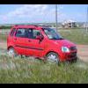
- Город:Омск
- Автомобиль: Opel Agila 1.2
- @Упоминание
Отправлено 06 Январь 2010 — 12:50
Может кому пригодится.
[attachmentid=45629]
Полная версия в двух частях находится в сообщении #88.
Сообщение отредактировал Alex140777: 12 Январь 2010 — 13:48
#19
![]()
Alex140777
Alex140777
-
- Постоянные посетители
- Cообщений: 6
Читатель
- Город:Омск
- Автомобиль: Opel Agila 1.2
- @Упоминание
Отправлено 12 Январь 2010 — 13:43
Техническое описание на Opel Agila, качество среднее но все понятно…..
1. часть №1 — deposit
2. часть №2 — deposit
Сообщение отредактировал Alex140777: 11 Март 2010 — 14:29
#20
![]()
sergg66
sergg66
- Город:С-Петербург (Петродворец)
- Автомобиль: Opel Agila 1.0
- @Упоминание
Отправлено 08 Апрель 2010 — 10:24