-
Page 1
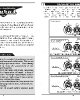
TAURUS 60 Turbomachinery Package Specification Oil & G a s A pp lic ations Compressor Set and Mechanical Drive… -
Page 2
TURBOMACHINERY PACKAGE SPECIFICATION Taurus 60 Compressor Set and Mechanical Drive Solar Turbines Incorporated P.O. Box 85376 San Diego, CA 92186-5376 Caterpillar is a trademark of Caterpillar Inc. Solar, Taurus, SoLoNOx, and Turbotronic are trademarks of Solar Turbines Incorporated. All other trademarks, service marks, or registered trademarks appearing in this specification are the intellectual property of their respective companies. -
Page 3: Table Of Contents
Turbomachinery Package Specification Taurus 60 Compressor Set and Mechanical Drive Table of Contents INTRODUCTION ……………………5 General Description………………….5 Overview…………………….5 Terminology……………………5 TAURUS 60 GAS TURBINE MECHANICAL DRIVE ………….6 General Description………………….6 Package Description ………………….6 TAURUS 60 GAS TURBINE………………..10 General Description………………….10 SOLAR COMPRESSOR SET PACKAGES ……………..13 Compressor Set Packages……………….13…
-
Page 4
Turbomachinery Package Specification Taurus 60 Compressor Set and Mechanical Drive QUALITY ASSURANCE AND TESTING …………….67 17.1 Quality Assurance ………………….67 17.2 Testing……………………..67 PRESERVATION, INSTALLATION, AND DOCUMENTATION………..70 18.1 General Description………………….70 18.2 Preservation …………………….70 18.3 Site Requirements………………….70 18.4 Mechanical Installation ………………..71 18.5 Documentation ………………….71 CERTIFICATION……………………73… -
Page 5
Suppression Fire Cylinder Cabinets ………….51 Figure 23. Typical Water Mist Suppression Fire Cylinder Cabinet ……….52 Figure 24. Typical Enclosed Taurus 60 Package with Exhaust and Inlet Systems ….54 Figure 25. Typical Taurus 60 High Velocity Air Inlet System………….56 Figure 26. -
Page 6: Introduction
Taurus 60 compressor sets and mechanical drives represent years of intensive engineering and manufacturing design. Solar gas turbines are manufactured to rigid industrial standards and are thoroughly tested in modern facilities. Solar’s operations are certified by Det Norske Veritas (DNV) to conform to International Standardization Organization (ISO) 9001:2000 Standard for Quality Management Systems.
-
Page 7: Taurus 60 Gas Turbine Mechanical Drive
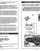
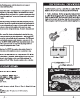
Figure 1. Typical Taurus 60 Gas Turbine Mechanical Drive Package Description The Taurus 60 gas turbine package is installed on a steel base frame referred to as the skid. The skid is a structural steel assembly with beam sections and cross members welded together to form a rigid foundation.
-
Page 8: Figure 2. Typical Taurus 60 Mechanical Drive Service Connections
Motor starters and contactors are not provided. 2.2.2 Service Connections The Taurus 60 Mechanical Drive is supplied with self-contained systems for starting, fuel, lube oil and control. All service connections (Figure 2) are conveniently located on the outer edge of the skid.
-
Page 9
Turbomachinery Package Specification Taurus 60 Compressor Set and Mechanical Drive Table 1. Package Specifications Dimensions Approximate Package Measurements Height, Unenclosed 2.72 m (8 ft 11 in.) Height, Enclosed 3.20 m (10 ft 6 in.) Width (to skid edges) 2.46 m (8 ft 1 in.) -
Page 10
Turbomachinery Package Specification Taurus 60 Compressor Set and Mechanical Drive Single-Phase Lighting and Space Heater Voltage Optional Package Lighting and Space Heater 120, 220, 230, or 240 VAC, 50 Hz or 60 Hz Voltage Ratings Ingress Protection (IP) Ratings Onskid Junction Boxes… -
Page 11: Taurus 60 Gas Turbine
The gas turbine combines high performance operation with rugged industrial construction. This design philosophy allows for high efficiency, low maintenance, and a long service life. The Taurus 60 gas turbine is designed for a high degree of compliance with American Petroleum Institute (API) requirements.
-
Page 12: Figure 4. Typical Combustion Process
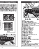
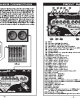
Turbomachinery Package Specification Taurus 60 Compressor Set and Mechanical Drive 3.1.1 Principles of Operation During the typical combustion process (Figure 4), air is drawn into the gas turbine air inlet and is compressed by the multi-stage, axial-flow engine compressor. The compressed air is directed into the annular combustion chamber at a steady flow.
-
Page 13
Turbomachinery Package Specification Taurus 60 Compressor Set and Mechanical Drive Power Turbine Type Reaction Number of Stages Maximum Speed 14,300 rpm Bearings Radial 3 Tilt Pad with Proximity Probes Thrust 1 Tilt Pad with Resistance Temperature Device Probes Construction Materials… -
Page 14: Solar Compressor Set Packages
Table 3 lists the Solar compressor products that are suitable for operation with the Taurus 60 gas turbine. Solar’s approach to compressor design is to maximize simplicity and flexibility. Solar gas compressors are designed to achieve a minimum of three years of continuous full-load duty between inspections, and major components are designed for 20 years of continuous operation.
-
Page 15: Figure 6. Cutaway Diagram Of A Solar Gas Compressor
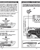
Turbomachinery Package Specification Taurus 60 Compressor Set and Mechanical Drive For more details about Solar centrifugal compressors, please consult Solar’s engineering for project specific gas compressors. Figures 6 and 7 show the internal construction of typical Solar compressors. Figure 6. Cutaway Diagram of a Solar Gas Compressor Figure 7.
-
Page 16
Turbomachinery Package Specification Taurus 60 Compressor Set and Mechanical Drive Table 3. Typical Solar Gas Compressors Maximum Pressure Maximum Flow Maximum Total Head Compressor Number Rating Family of Stages psig /min /min kJ/kg ft-lb For Gas Production Applications 1-10 20 700… -
Page 17
Turbomachinery Package Specification Taurus 60 Compressor Set and Mechanical Drive Seal Gas System The seal gas system consists of a primary and secondary gas face seal to prevent the escape of process gas for each shaft end. The primary dry seal takes the full pressure drop. -
Page 18
Turbomachinery Package Specification Taurus 60 Compressor Set and Mechanical Drive 4.2.7 Hydrostatic Testing Hydrostatic pressure testing of all compressor casings and end caps is done per API 617 for 30 minutes at 1.5 times the maximum casing design pressure, regardless of application. -
Page 19: Mechanical Drive Packages
Mechanical Drive Packages Mechanical Drives The Taurus 60 gas turbine mechanical-drive package is designed for a variety of driven equipment, including centrifugal pumps and centrifugal, rotary, and reciprocating compressors. The Taurus 60 gas turbine is well suited to drive pumps and compressors, where its variable-speed capability can be used to advantage in adjusting to changing specific gravity and flow.
-
Page 20
Turbomachinery Package Specification Taurus 60 Compressor Set and Mechanical Drive Single-Source Responsibility Solar is able to provide overall coordination to ensure that the unitized package will perform to its full potential with a minimum of installation time and cost. Performance characteristics of the driver and driven equipment are analyzed to provide an optimum match at design and off-design conditions. -
Page 21: Gearbox
Turbomachinery Package Specification Taurus 60 Compressor Set and Mechanical Drive Gearbox General Description If required, a gearbox (Figure
can be provided selected specifically for compressor set and mechanical drive applications. The gearbox uses few moving parts, providing high reliability and ease of assembly and disassembly. The gearbox is designed for continuous-duty operation and matches the output speed of the turbine or tandem compressor to the required operating speed of the driven compressor.
-
Page 22
Turbomachinery Package Specification Taurus 60 Compressor Set and Mechanical Drive The gearbox is mounted on the driven skid and, together with the input shaft coupling, is lubricated and cooled by forced-fed lubricating oil from the turbine. Gearbox journal and thrust bearing temperatures are monitored by two simplex resistance temperature devices (RTDs) at each radial bearing and two per thrust face on the thrust bearing. -
Page 23: Start System
Turbomachinery Package Specification Taurus 60 Compressor Set and Mechanical Drive Start System General Description The start system provides torque to initiate engine rotation and to assist the engine to reach a self-sustaining speed. The start system consists of either a direct-drive AC starter motor driven by a solid-state variable frequency drive (VFD) or an optional pneumatic start system.
-
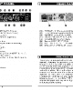
Page 24: Figure 9. Typical Direct-Drive Ac Starter Motor And Variable Frequency Drive
Turbomachinery Package Specification Taurus 60 Compressor Set and Mechanical Drive Figure 9. Typical Direct-Drive AC Starter Motor and Variable Frequency Drive RADIO VARIABLE INTERFERENCE FREQUENCY LINE REACTOR DRIVE FILTER AC POWER CONNECTION TURBINE CLUTCH ASSEMBLY MOTOR Figure 10. Typical Direct-Drive AC Start System 7.2.4…
-
Page 25
Turbomachinery Package Specification Taurus 60 Compressor Set and Mechanical Drive Variable Frequency Drive (cont.) Power Factor 0.96 Efficiency Minimum/Maximum Operating Temperature -10 to 40°C (14 to 104°F) Heat Rejection — 380 to 460 VAC Input 1780 watts Input Fuse Rating… -
Page 26: Pneumatic Start System (Optional)
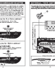
Turbomachinery Package Specification Taurus 60 Compressor Set and Mechanical Drive Pneumatic Start System (Optional) The pneumatic start system, (Figure 11) can use either process gas or compressed air as a power source. The standard system consists of a strainer, shutoff valve, pneumatic starter motor, and associated stainless steel piping and manifolds.
-
Page 27: Fuel System
Turbomachinery Package Specification Taurus 60 Compressor Set and Mechanical Drive Fuel System General Description The fuel system (Figure 12), in conjunction with the control system, includes all necessary components to control ignition and fuel flow during all modes of operation.
-
Page 28
Turbomachinery Package Specification Taurus 60 Compressor Set and Mechanical Drive • Pilot air operated secondary gas fuel shutoff valve • Pilot air operated gas vent valve • Electrically operated fuel control valve • Torch with shutoff valve and pressure regulators •… -
Page 29
Turbomachinery Package Specification Taurus 60 Compressor Set and Mechanical Drive Gas Fuel System (cont.) Response Time Less Than 100 msec From 10-to-90% Stroke Valve Body Aluminum (Standard) Stainless Steel (Optional) Gas Fuel Filter (Conventional Units Only) 10 Micron Customer-Furnished Pilot Air System… -
Page 30: Lubrication System
Turbomachinery Package Specification Taurus 60 Compressor Set and Mechanical Drive Lubrication System General Description The lubrication system, (Figure 13) circulates oil under pressure to the gas turbine and driven equipment. Lube oil is supplied from the lube oil tank located in the driver frame.
-
Page 31: Figure 13. Typical Lube Oil System
Turbomachinery Package Specification Taurus 60 Compressor Set and Mechanical Drive fire, control system failure, emergency stop, or if a turbine over speed is detected by the backup system. 9.1.5 Duplex Lube Oil Filter System The duplex lube oil filter system is supplied with a filter transfer valve and filter differential pressure indication with alarm.
-
Page 32
Turbomachinery Package Specification Taurus 60 Compressor Set and Mechanical Drive 9.1.7 Lube Oil Vent Flame Arrestor The lube oil vent flame arrestor prevents an ignition source from entering the lube oil tank. The flame arrestor is loose shipped for offskid installation by others. -
Page 33
Turbomachinery Package Specification Taurus 60 Compressor Set and Mechanical Drive Main Lube Oil Duplex Filters Type Self-Supporting Pedestal Duplex Filters 10 Micron Certification ASME, Section VIII, Division 1 Backup Lube Oil Pump Filter Type Bowl Filter Minimum/Maximum Operating Temperatures -54° to 135°C (-65° to 275°F) Simplex Filter β… -
Page 34
(c) The maximum total design pressure drop of the off skid oil cooler loop including supply and return lines shall not exceed 276 Kpad (40 psid) at the design flow rate and an oil viscosity of 60 ssu (10.5 centistokes). No check valves are allowed in the oil cooler loop. This is recommended for all… -
Page 35: Turbotronic 4 Control System
Turbomachinery Package Specification Taurus 60 Compressor Set and Mechanical Drive Turbotronic 4 Control System 10.1 General Description The Turbotronic 4 control system controls and monitors the turbomachinery package including the gas turbine and driven equipment. The system scope can be expanded to include monitoring and/or control of balance of plant equipment that is directly package related.
-
Page 36: Figure 14. Typical Onskid Control System
Turbomachinery Package Specification Taurus 60 Compressor Set and Mechanical Drive OPTIONAL AUXILIARY CONSOLE PACKAGE SKID OPTIONAL REMOTE DESKTOP COMPUTER CONTROLNET ETHERNET TT4000 TT4000S OPERATOR PANEL CONTROL PROCESSOR I/O MODULES TURBINE CONTROL PANEL BACKUP SHUTDOWN SYSTEM TT4000 FIRE & GAS SYSTEM…
-
Page 37: Component Descriptions
Turbomachinery Package Specification Taurus 60 Compressor Set and Mechanical Drive SAFE AREA OPERATOR INTERFACE MOTOR CONTROL CENTER TT4000 VARIABLE FREQUENCY DRIVES TURBINE CONTROL PANEL PRIMARY CONTROL SYSTEM COMPONENTS ONSKID OPERATOR INTERFACE SERIAL LINK TO CONTROLLOGIX SUPERVISORY CONTROLLER CONTROL TT4000S CONTROLNET…
-
Page 38: System Monitoring And Control Functions
Turbomachinery Package Specification Taurus 60 Compressor Set and Mechanical Drive The system is configurable from the control processor. It detects preprogrammed alarm and shutdown levels. See the specification tables for a list of monitored channels. 10.3.5 Backup Shutdown System The backup shutdown system shuts the package down in a safe and orderly manner without damage to the equipment in the event of a failure in the primary system.
-
Page 39
Turbomachinery Package Specification Taurus 60 Compressor Set and Mechanical Drive The fuel control valve gradually opens and admits fuel into the combustor through the injectors. The inlet guide vanes open and the bleed valve gradually closes. Fuel flow, engine temperature, and turbine speed all increase. Once starter dropout speed is exceeded, the starter freewheels and is de-energized. -
Page 40: Tt4000 Display And Monitoring System
Turbomachinery Package Specification Taurus 60 Compressor Set and Mechanical Drive 10.5 TT4000 Display and Monitoring System The TT4000 display and monitoring system provides extensive data collection and display capabilities. On a typical project, two standard versions of the product are used.
-
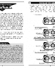
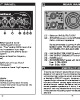
Page 41: Figure 17. Typical Tt4000 Operation Summary Screen
Turbomachinery Package Specification Taurus 60 Compressor Set and Mechanical Drive Figure 17. Typical TT4000 Operation Summary Screen Figure 18. Typical TT4000 Strip Chart Screen © 2009 Solar Turbines Incorporated. All rights reserved. TPS60CSMD/309…
-
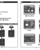
Page 42: Figure 19. Typical Tt4000S Engine Summary Screen
Turbomachinery Package Specification Taurus 60 Compressor Set and Mechanical Drive Figure 19. Typical TT4000S Engine Summary Screen 10.5.2 TT4000S Display Screens The TT4000S displays a comparable set of screens to the full TT4000 except that the data is in numerical form and graphics are limited (Figure 19).
-
Page 43
Turbomachinery Package Specification Taurus 60 Compressor Set and Mechanical Drive are available for transmittal. Interface modules mount in the controller rack and connect through the rack’s backplane. Available connections are: • ControlLogix 1.5 • Ethernet • Data Highway Plus •… -
Page 44
Turbomachinery Package Specification Taurus 60 Compressor Set and Mechanical Drive Offskid Control Console Dimensions One-Bay Control Console Height 2286 mm (90 in.) Width 914 mm (36 in.) Depth 800 mm (32 in.) Approximate Weight 570 kg (1250 lb) Two-Bay Control Console Height 2286 mm (90 in.) -
Page 45: Compressor Control And Monitoring
Turbomachinery Package Specification Taurus 60 Compressor Set and Mechanical Drive Compressor Control and Monitoring 11.1 General Description The following sections outline the control and monitoring options available for compressors and mechanical drives. 11.1.1 Process Control The process control options provide unit control based on the gas compressor suction pressure, discharge pressure, and flow (or combinations of these parameters).
-
Page 46
Turbomachinery Package Specification Taurus 60 Compressor Set and Mechanical Drive • Purchaser piping and instrumentation diagram including suction and recycle pipe size and schedule • Anti-surge control (recycle) valve and specification sheet, unless included in Solar’s scope • Suction and discharge gas temperature signal (100-ohm platinum resistance… -
Page 47
Turbomachinery Package Specification Taurus 60 Compressor Set and Mechanical Drive available at the time of this proposal. It may be necessary to select a different valve, or possibly a combination of valves, once complete compressor system design information is received. Any such change will have a commercial impact. -
Page 48: Enclosure
Turbomachinery Package Specification Taurus 60 Compressor Set and Mechanical Drive Enclosure 12.1 General Description The enclosure housing, Figure 20, is a completely self-contained, weatherproof, insulated, and sound-attenuated system. The enclosure is mounted on the package skid and supported by a heavy-duty frame. The enclosure sides include removable panels and/or doors to allow access to major components for inspection and maintenance and to permit removal of components by forklift or overhead crane.
-
Page 49: Standard Features
Turbomachinery Package Specification Taurus 60 Compressor Set and Mechanical Drive 12.2 Standard Features 12.2.1 Inlet and Exhaust Ventilation Silencers The enclosure ventilation openings are equipped with silencers with weather louvers. 12.2.2 Single-Fan Ventilation A single high efficiency motor-driven fan provides enclosure ventilation. The ventilation fan provides airflow to ensure the enclosure internal air temperature remains within acceptable limits.
-
Page 50: Figure 21. Typical Fire And Gas System
Turbomachinery Package Specification Taurus 60 Compressor Set and Mechanical Drive of the panels in decibels is available upon request. Further information is available in Solar’s publication SPNP, “Noise Prediction Guidelines for Industrial Gas Turbines.” 12.2.8 Exterior Connections Connections for oil vent line, fire and gas suppression systems, and gas turbine air inlet and exhaust are terminated outside the enclosure.
-
Page 51: Optional Features
Turbomachinery Package Specification Taurus 60 Compressor Set and Mechanical Drive mounted on the gas turbine enclosure or at the suppression skid. If a fire is detected, the fire detectors transmit an electrical signal to the fire system control panel to activate the fire alarm and suppression system.
-
Page 52: Figure 22. Typical Co
Turbomachinery Package Specification Taurus 60 Compressor Set and Mechanical Drive solenoids located in the CO fire suppression cylinder cabinets, Figure 22. On receipt of this signal, the solenoid actuated control heads activate the CO cylinders, releasing CO into the enclosure. CO pressure actuates the pressure trip operated dampers that close all vent openings.
-
Page 53: Figure 23. Typical Water Mist Suppression Fire Cylinder Cabinet
Optional Ventilation Fan Motor Voltage Ratings 380 VAC, 400 VAC, and 415 VAC (50 Hz) 460 VAC and 575 VAC (60 Hz) Primary Enclosure Lighting Voltage 220 VAC (50 Hz) or 110 VAC (60 Hz) Standby Enclosure Lighting Voltage 120 VDC Sound Pressure Level…
-
Page 54
Turbomachinery Package Specification Taurus 60 Compressor Set and Mechanical Drive Fire Cylinder Cabinets (Cont’d) Fire Cylinder Cabinet, Extended Release Height 213 cm (84 in.) Width 152 cm (60 in.) Depth 53 cm (21 in.) Approximate Cabinet Weight 429 kg (946 lb), Without Cylinders… -
Page 55: Air Inlet System
The filter house has a back outlet and requires ducting and a support frame. Figure 24. Typical Enclosed Taurus 60 Package with Exhaust and Inlet Systems © 2009 Solar Turbines Incorporated. All rights reserved.
-
Page 56
Turbomachinery Package Specification Taurus 60 Compressor Set and Mechanical Drive 13.1.2 Self-Cleaning Barrier Type Air Filter The self-cleaning barrier type air filter system is suitable for extreme environments where dust loading or cold-weather operation is a concern. This system is available in an updraft configuration. -
Page 57: Figure 25. Typical Taurus 60 High Velocity Air Inlet System
Turbomachinery Package Specification Taurus 60 Compressor Set and Mechanical Drive Figure 25. Typical Taurus 60 High Velocity Air Inlet System 13.1.4 Offshore / Coastal Medium Velocity Type Air Filter The offshore and coastal medium velocity type air filter system (Figure 26) is suitable for use in offshore and coastal applications.
-
Page 58: Figure 26. Typical Taurus 60 Medium Velocity Air Inlet System
Turbomachinery Package Specification Taurus 60 Compressor Set and Mechanical Drive Figure 26. Typical Taurus 60 Medium Velocity Air Inlet System 13.1.5 Insect Screens Optional insect screens can be installed on the air inlet filters (except for self-cleaning filters). This option is used when large numbers of insects are present. The screen is designed to reduce the velocity of the air stream sufficiently to allow most insects to fly away.
-
Page 59
Turbomachinery Package Specification Taurus 60 Compressor Set and Mechanical Drive Table 12. Air Inlet System Specifications Air Inlet System Pressure Drop Less Than 102 mm (4 in.) H O with a Clean Air Filter Ducting Loads Should Not Be Applied In Any Direction… -
Page 60
6°C (10°F) below the minimum temperature to which any part of the air system is exposed or between 1.6°C and 60°C (35°F and 140°F). Air should be free of all corrosive contaminants, hazardous gases, flammables, and toxics. -
Page 61: Exhaust System
Brackets are available for mounting the silencer in a vertical or horizontal position. Figure 24 shows a typical Taurus 60 mechanical drive with a radial exhaust silencer. 14.2 Turbine Exhaust Heat Recovery System High thermal efficiencies can be obtained by using the gas turbine exhaust heat energy.
-
Page 62
Turbomachinery Package Specification Taurus 60 Compressor Set and Mechanical Drive Table 13. Exhaust System Specifications Exhaust System Temperature Class Total System Pressure Loss Should Not Exceed 152 mm (6 In.) of Water Exhaust Temperature 538°C (1000°F) Nominal System Back Pressure 203 mm (8 in.) of water, See Note (a) -
Page 63: Accessory Equipment
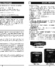
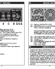
Turbomachinery Package Specification Taurus 60 Compressor Set and Mechanical Drive Accessory Equipment 15.1 Battery Charger System The battery charger system consists of a battery charger (Figure 27) and batteries to provide 120 VDC emergency power to the control console, fuel valve, bleed valve and variable guide vane actuators, and the DC backup lube oil pump.
-
Page 64: Figure 28. Turbine Cleaning System
Turbomachinery Package Specification Taurus 60 Compressor Set and Mechanical Drive Figure 28. Turbine Cleaning System 15.2.1 On-Crank Cleaning System The on-crank cleaning system only operates at gas turbine cranking speed with the fuel system and ignition system deactivated. The gas turbine cranking and cleaning solution activation can be initiated from the control console or turbine control junction box.
-
Page 65
Table 14. Accessory Equipment Specifications Battery Charger System Charger Type Wall Mounted, Bottom Entry, IP30 Supply Voltage 240, 380, and 480 VAC, 50 or 60 Hz. Output Single Phase, 120 VDC, 20 amps Operating Temperature -10° to 50°C (14° to 122°F) -
Page 66: Marinization
Marinization 16.1 General Description The Taurus 60 Compressor Set and Mechanical Drives may be operated in offshore oil and gas applications. Depending upon operating conditions and movement of the underlying support structure, optional package modifications may be required. Solar turbomachinery packages operate successfully on the following types of offshore installations: •…
-
Page 67
Turbomachinery Package Specification Taurus 60 Compressor Set and Mechanical Drive • Bureau Veritas (BV) • Lloyd’s Register (LR) • American Bureau of Shipping (ABS) 16.1.6 Deck Deflection Limits The package supporting deck structure must have sufficient stiffness to maintain alignment of the turbine and driven equipment under dynamic vessel motion. Solar’s engineering specification ES 2379, “Offshore Product Motion Requirements for Oil &… -
Page 68: Quality Assurance And Testing
Turbomachinery Package Specification Taurus 60 Compressor Set and Mechanical Drive Quality Assurance and Testing 17.1 Quality Assurance Solar is an Industry Standards Organization (ISO) 9000 company with ISO 9001:2000 and 9002 certification. Several Solar gas turbine models and manufacturing processes have been «type»…
-
Page 69
Turbomachinery Package Specification Taurus 60 Compressor Set and Mechanical Drive • Power and heat rate measurements at partial and full load under ambient conditions • Turbine and driven equipment temperature measurement • Variable guide vane adjustment • Malfunction and safety devices testing… -
Page 70
Turbomachinery Package Specification Taurus 60 Compressor Set and Mechanical Drive 17.2.7 Customer Participation As an option, the customer may observe specified tests on a noninterference basis and/or hold point basis. 17.2.8 Weld Radiography As an option, radiographic welding inspections can be performed on a higher percentage of the gas fuel and/or lube oil system piping and manifolds. -
Page 71: Preservation, Installation, And Documentation
Turbomachinery Package Specification Taurus 60 Compressor Set and Mechanical Drive Preservation, Installation, and Documentation 18.1 General Description This chapter describes preservation, general installation requirements, and project documentation. 18.2 Preservation Long term or short term preservation can be provided for the engine and package. The type of preservation required is dependent on the following: •…
-
Page 72: Mechanical Installation
Turbomachinery Package Specification Taurus 60 Compressor Set and Mechanical Drive 18.4 Mechanical Installation 18.4.1 TPIM-1010 Solar’s document TPIM-1010 “Package Installation Guideline – Compressor Sets and Mechanical Drives” outlines the responsibilities of the Customer and Solar regarding installation of the package. It provides guidelines for the installation of the standard package design and the interface with the turbine driven equipment.
-
Page 73
Turbomachinery Package Specification Taurus 60 Compressor Set and Mechanical Drive If a resonance condition (interference) is found, then a fatigue analysis is performed to confirm the resonance will not cause fatigue failure in the shafting. 18.5.2 Lateral Analysis Report (Optional) A lateral forced response analysis of the driven equipment can be performed to confirm that any lateral critical speeds aren’t close enough to the operating speed range to cause… -
Page 74: Certification
Turbomachinery Package Specification Taurus 60 Compressor Set and Mechanical Drive Certification 19.1 General Description Solar’s leadership in the gas turbine industry is supported by its ability to comply with regulations, codes, and standards required by industry and/or regional authorities around the world.
-
Page 75: Conformité Européenne Mark
Turbomachinery Package Specification Taurus 60 Compressor Set and Mechanical Drive 19.4 Conformité Européenne Mark For installations that require Conformité Européenne (CE) Mark certification, Solar complies with the CE Mark codes and standards adopted by local authorities and government entities. Sources for these codes and standards include the following European Union (EU) directives: •…
-
Page 76: International Electrotechnical Commission Safety Assessment
Turbomachinery Package Specification Taurus 60 Compressor Set and Mechanical Drive 19.5 International Electrotechnical Commission Safety Assessment International Electrotechnical Commission (IEC) 61508 is an international standard that describes a standardized approach to Asses the functional safety of electric, electronic, and programmable electronic safety-related systems. This standard is based on a life- cycle evaluation of system reliability and safety level determination.
-
Page 77: Summary
Turbomachinery Package Specification Taurus 60 Compressor Set and Mechanical Drive 19.7 Summary Solar has a continuing program to support customers in ensuring that Solar’s products conform to applicable codes and regulations. Solar also has the resources to provide customer guidance and assistance in this process.
-
Page 78: Support Services
Turbomachinery Package Specification Taurus 60 Compressor Set and Mechanical Drive Support Services 20.1 Construction Services Solar’s Construction Services organization offers a comprehensive range of equipment and services to successfully meet power system expectations and needs. Our experience takes us to many parts of the world, onshore and offshore, managing various types of power configurations.
-
Page 79: Contract Power And Leasing Services
Turbomachinery Package Specification Taurus 60 Compressor Set and Mechanical Drive 20.3 Contract Power and Leasing Services Solar offers numerous financing options. All or part of a project can be financed, offered under a lease agreement, or installed on a service tariff with a performance contract.
-
Page 80: Conversion Chart
Turbomachinery Package Specification Taurus 60 Compressor Set and Mechanical Drive Conversion Chart Conversion Factors To Convert From To Convert To English To S.I. Metric Multiply By Old Metric Multiply By 1.0551 kcal 0.252 Btu/h 0.2931 kcal/h 0.252 Btu/scf kJ/nm 39.3694 kcal/nm 9.382…
-
Page 81: List Of Abbreviations
Turbomachinery Package Specification Taurus 60 Compressor Set and Mechanical Drive List of Abbreviations Abbreviations American Bureau of Shipping Absolute AGMA American Gear Manufacturers Association American Petroleum Institute AS/NZS Australian/New Zealand Standard ASME American Society of Mechanical Engineers Atmosphere Absolute ATEX…
-
Page 82
Turbomachinery Package Specification Taurus 60 Compressor Set and Mechanical Drive Abbreviations (Cont’d) Horsepower HRSG Heat Recovery Steam Generator International Electrotechnical Commission IEEE Institute of Electrical and Electronic Engineers Inch in. Hg Inches of Mercury in. H Inches of Water Ingress Protections… -
Page 83
Turbomachinery Package Specification Taurus 60 Compressor Set and Mechanical Drive Abbreviations (Cont’d) Power Factor Product Information Letter Permanent Magnet Generator Pounds/Square Inch psia Pounds/Square Inch Absolute psig Pounds/Square Inch Gauge Revolutions Per Minute Resistance Temperature Device Standard* Cubic Foot scfd…
Посмотреть инструкция для Taurus Abductor and Adductor IT95 бесплатно. Руководство относится к категории фитнес-оборудование, 1 человек(а) дали ему среднюю оценку 7.5. Руководство доступно на следующих языках: английский. У вас есть вопрос о Taurus Abductor and Adductor IT95 или вам нужна помощь? Задайте свой вопрос здесь
Не можете найти ответ на свой вопрос в руководстве? Вы можете найти ответ на свой вопрос ниже, в разделе часто задаваемых вопросов о Taurus Abductor and Adductor IT95.
Сколько часов в неделю нужно тренироваться взрослому человеку?
Взрослым рекомендуется выполнять умеренно интенсивные упражнения не менее 2,5 часов в неделю. Желательно распределить их на несколько дней.
Какой максимально допустимый пульс взрослого человека?
Можно определить для себя максимально допустимый пульс, отняв от 220 свой возраст.
Инструкция Taurus Abductor and Adductor IT95 доступно в русский?
К сожалению, у нас нет руководства для Taurus Abductor and Adductor IT95, доступного в русский. Это руководство доступно в английский.
Не нашли свой вопрос? Задайте свой вопрос здесь
- Manuals
- Brands
- EWM Manuals
- Welding System
- Taurus 351
- Operating instructions manual
-
Contents
-
Table of Contents
-
Bookmarks
Quick Links
Operating instructions
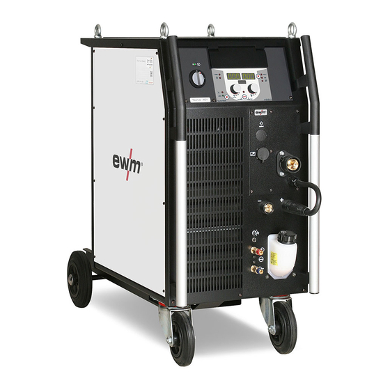
Welding machine
EN
Taurus 351-551 Synergic S MM FDG/FDW
099-005341-EW501
Observe additional system documents!
27.01.2016
Related Manuals for EWM Taurus 351
Summary of Contents for EWM Taurus 351
-
Page 1
Operating instructions Welding machine Taurus 351-551 Synergic S MM FDG/FDW 099-005341-EW501 Observe additional system documents! 27.01.2016… -
Page 2: General Instructions
+49 2680 181-0. A list of authorised sales partners can be found at www.ewm-group.com. Liability relating to the operation of this equipment is restricted solely to the function of the equipment.
-
Page 3: Table Of Contents
Contents Notes on the use of these operating instructions Contents Contents …………………………3 Safety instructions ……………………..5 Notes on the use of these operating instructions …………….5 Explanation of icons ……………………6 …
-
Page 4
Technical data……………………….45 Taurus 351 Synergic S MM FDG ………………..45 Taurus 351 Synergic S MM VRD FDG ………………46 Taurus 351 Synergic S MM FDW ………………..47 Taurus 401 Synergic S MM FDG ………………..48 … -
Page 5: Safety Instructions
Safety instructions Notes on the use of these operating instructions Safety instructions Notes on the use of these operating instructions DANGER Working or operating procedures which must be closely observed to prevent imminent serious and even fatal injuries. • Safety notes include the «DANGER» keyword in the heading with a general warning symbol. •…
-
Page 6: Explanation Of Icons
Safety instructions Explanation of icons Explanation of icons Symbol Description Special technical points which users must observe. Correct Wrong Press Do not press Press and keep pressed Turn Switch Switch off machine Switch on machine enter the menu ENTER Navigating in the menu NAVIGATION Exit the menu EXIT…
-
Page 7: General
Safety instructions General General DANGER Electric shock! Welding machines use high voltages which can result in potentially fatal electric shocks and burns on contact. Even low voltages can cause you to get a shock and lead to accidents. • Do not touch any live parts in or on the machine! •…
-
Page 8
Safety instructions General WARNING Explosion risk! Apparently harmless substances in closed containers may generate excessive pressure when heated. • Move containers with inflammable or explosive liquids away from the working area! • Never heat explosive liquids, dusts or gases by welding or cutting! Smoke and gases! Smoke and gases can lead to breathing difficulties and poisoning. -
Page 9
Safety instructions General CAUTION Obligations of the operator! The respective national directives and laws must be observed for operation of the machine! • National implementation of the framework directive (89/391/EWG), as well as the associated individual directives. • In particular, directive (89/655/EWG), on the minimum regulations for safety and health protection when staff members use equipment during work. -
Page 10
Safety instructions General CAUTION EMC Machine Classification In accordance with IEC 60974-10, welding machines are grouped in two electromagnetic compatibility classes — See 8 Technical data chapter: Class A machines are not intended for use in residential areas where the power supply comes from the low-voltage public mains network. -
Page 11: Transport And Installation
Safety instructions Transport and installation Transport and installation WARNING Incorrect handling of shielding gas cylinders! Incorrect handling of shielding gas cylinders can result in serious and even fatal injury. • Observe the instructions from the gas manufacturer and in any relevant regulations concerning the use of compressed air! •…
-
Page 12: Lifting By Crane
Safety instructions Transport and installation 2.4.1 Lifting by crane WARNING Risk of injury during lifting by crane When lifting the machine by crane, persons may be severely injured by falling machines or mount-on components. • Simultaneous lifting of system components such as power source wire feeder or cooling unit without suitable crane components is not allowed.
-
Page 13: Ambient Conditions
Safety instructions Transport and installation 2.4.2 Ambient conditions CAUTION Installation site! The machine must not be operated in the open air and must only be set up and operated on a suitable, stable and level base! • The operator must ensure that the ground is non-slip and level, and provide sufficient lighting for the place of work.
-
Page 14: Intended Use
(see the documentation in the relevant chapter). Use and operation solely with the following machines A suitable power source (system component) is required in order to operate the wire feed unit! Taurus 351, 401, 451, 551 Synergic S MM FDG/FDW drive 4X (LP/HP/MMA) …
-
Page 15: Documents Which Also Apply
3.3.1 Warranty For more information refer to the «Warranty registration» brochure supplied and our information regarding warranty, maintenance and testing at www.ewm-group.com! 3.3.2 Declaration of Conformity The designated machine conforms to EC Directives and standards in terms of its design and construction: •…
-
Page 16: Machine Description — Quick Overview
Machine description – quick overview Front view Machine description – quick overview Front view Coolant tank and quick connect coupling of coolant supply and return are only fitted in machines with water cooling. Figure 4-1 099-005341-EW501 27.01.2016…
-
Page 17
Machine description – quick overview Front view Item Symbol Description Lifting lug Voltage reduction device (VRD) signal light The VRD signal light is illuminated when the voltage reduction device is operating without fault and the output voltage is reduced to a value specified in the relevant standard (see technical data). -
Page 18: Rear View
Machine description – quick overview Rear view Rear view Figure 4-2 099-005341-EW501 27.01.2016…
-
Page 19
Machine description – quick overview Rear view Item Symbol Description 7-pole connection socket (digital) For connecting digital accessory components 7-pole connection socket (digital) Wire feed unit connection PC interface, serial (D-Sub connection socket, 9-pole) Connector plug, welding current «+» Welding current connection on wire feed unit Connection socket, “-”… -
Page 20: Design And Function
Design and function General Design and function General WARNING Risk of injury from electric shock! Contact with live parts, e.g. welding current sockets, is potentially fatal! • Follow safety instructions on the opening pages of the operating instructions. • Commissioning may only be carried out by persons who have the relevant expertise of working with arc welding machines! •…
-
Page 21: Installation
Design and function Installation CAUTION Damage due to incorrect connection! Accessory components and the power source itself can be damaged by incorrect connection! • Only insert and lock accessory components into the relevant connection socket when the machine is switched off. •…
-
Page 22: Notes On The Installation Of Welding Current Leads
Design and function Notes on the installation of welding current leads Notes on the installation of welding current leads Incorrectly installed welding current leads can cause faults in the arc (flickering). Lay the workpiece lead and hose package of power sources without HF igniter (MIG/MAG) for as long and as close as possible in parallel.
-
Page 23
Design and function Notes on the installation of welding current leads Use an individual welding lead to the workpiece for each welding machine! Figure 5-2 Fully unroll welding current leads, torch hose packages and intermediate hose packages. Avoid loops! Always keep leads as short as possible! Lay any excess cable lengths in meanders. -
Page 24: Welding Torch Cooling System
Design and function Welding torch cooling system Welding torch cooling system CAUTION Coolant mixtures! Mixtures with other liquids or the use of unsuitable coolants result in material damage and renders the manufacturer’s warranty void! • Only use the coolant described in this manual (overview of coolants). •…
-
Page 25: Adding Coolant
Design and function Welding torch cooling system 5.6.3 Adding coolant The unit is supplied ex works with a minimum level of coolant. Figure 5-4 Item Symbol Description Coolant tank cap Coolant filter sieve Coolant tank «Min» mark Minimum coolant level •…
-
Page 26: Mains Connection
Design and function Mains connection Mains connection DANGER Hazard caused by improper mains connection! An improper mains connection can cause injuries or damage property! • Only use machine with a plug socket that has a correctly fitted protective conductor. • If a mains plug must be fitted, this may only be carried out by an electrician in accordance with the relevant national provisions or regulations! •…
-
Page 27: Connecting The Intermediate Hose Package To The Power Source
Design and function Connecting the intermediate hose package to the power source Connecting the intermediate hose package to the power source Some wire electrodes (e.g. self-shielding cored wire) are welded using negative polarity. In this case, the welding current lead should be connected to the «-» welding current socket, and the workpiece lead should be connected to the «+»…
-
Page 28: Shielding Gas Supply (Shielding Gas Cylinder For Welding Machine)
Design and function Shielding gas supply (shielding gas cylinder for welding machine) • Insert the end of the hose package through the strain relief of the hose package and lock by turning to the right. • Insert the plug on the welding current lead into the welding current connection socket «+» and lock. •…
-
Page 29: Connection
Design and function Shielding gas supply (shielding gas cylinder for welding machine) 5.9.1 Connection • Place the shielding gas cylinder into the relevant cylinder bracket. • Secure the shielding gas cylinder using a securing chain. Figure 5-7 Item Symbol Description Pressure regulator Shielding gas cylinder Output side of the pressure regulator…
-
Page 30: Aligning The Cable Resistance
Design and function Aligning the cable resistance 5.10 Aligning the cable resistance The resistance value of cables can either be set directly or it can be aligned using the power source. The factory setting of the power sources is 8 mΩ. This value correponds to a 5 m earth cable, a 1.5 m intermediate hose package and a 3 m water-cooled welding torch.
-
Page 31
Design and function Aligning the cable resistance 1 Preparation • Switch off the welding machine. • Unscrew the gas nozzle from the welding torch. • Trim the welding wire, so that it is flush with the contact tip. • Retract the welding wire a little (approx. 50 mm) on the wire feeder. There should now be no more welding wire in the contact tip. -
Page 32: Mig/Mag Welding
Design and function MIG/MAG welding 5.11 MIG/MAG welding 5.11.1 Connection for workpiece lead Some wire electrodes (e.g. self-shielding cored wire) are welded using negative polarity. In this case, the welding current lead should be connected to the «-» welding current socket, and the workpiece lead should be connected to the «+»…
-
Page 33: Tig Welding
Design and function TIG welding 5.12 TIG welding 5.12.1 Welding torch connection TIG welding torches to be connected to a Euro torch connector are available in two versions: • TIG combi welding torches are connected to the Euro torch connector of the wire feeder and to the (-) welding current plug of the power source.
-
Page 34: 5.12.2 Connection For Workpiece Lead
Design and function TIG welding • Insert the central plug for the welding torch into the central connector and screw together with crown nut. • Insert the welding current plug of the combi welding torch into the (-) welding current connection socket and lock into place by turning to the right (only in case of a separate welding current connection).
-
Page 35: Mma Welding
Design and function MMA welding 5.13 MMA welding CAUTION Risk of being crushed or burnt. When replacing spent or new stick electrodes • Switch off machine at the main switch • Wear appropriate safety gloves • Use insulated tongs to remove spent stick electrodes or to move welded workpieces and •…
-
Page 36: Voltage Reducing Device (Vrd)
Design and function Remote control 5.13.2 Voltage reducing device (VRD) The voltage reduction device is only active on VRD machine versions. To increase safety, particularly in hazardous environments (like shipbuilding, pipe construction or mining), the machine is equipped with the VRD (Voltage-reducing device) voltage reduction device. The VRD signal light is illuminated, when the voltage reduction device is operating without fault and the output voltage is reduced to a value specified in the relevant standard (see technical data).
-
Page 37: Maintenance, Care And Disposal
Maintenance, care and disposal General Maintenance, care and disposal DANGER Improper maintenance and testing The equipment may only be cleaned, repaired or tested by specialist, skilled persons! A skilled person is one who, due to training, knowledge and experience, is able to recognise the dangers that can occur during testing of this equipment as well as possible subsequent damage and who is able to implement the required safety procedures.
-
Page 38: Monthly Maintenance Tasks
In addition to this, returns are also possible throughout Europe via EWM sales partners. Meeting the requirements of RoHS We, EWM AG Mündersbach, hereby confirm that all products supplied by us which are affected by the RoHS Directive, meet the requirements of the RoHS (Directive 2011/65/EU).
-
Page 39: Rectifying Faults
Rectifying faults Checklist for rectifying faults Rectifying faults All products are subject to rigorous production checks and final checks. If, despite this, something fails to work at any time, please check the product using the following flowchart. If none of the fault rectification procedures described leads to the correct functioning of the product, please inform your authorised dealer.
-
Page 40: Error Messages
Rectifying faults Error messages Error messages A welding machine error is indicated by an error code being displayed (see table) on the display on the machine control. In the event of a machine error, the power unit is shut down. The display of possible error numbers depends on the machine version (interfaces/functions).
-
Page 41
Rectifying faults Error messages Error Category Possible cause Remedy Error 56 Mains phase failure Check mains voltages (no Pha) Error 59 Machine incompatible Check machine used (Unit?) Legend for categories (error reset) a) The error message will disappear once the error has been rectified. b) The error message can be reset by pressing a key button: Welding machine control Key button… -
Page 42: Resetting Jobs (Welding Tasks) To The Factory Settings
Rectifying faults Resetting JOBs (welding tasks) to the factory settings Resetting JOBs (welding tasks) to the factory settings All customised welding parameters that are stored will be replaced by the factory settings. 7.3.1 Resetting a single JOB JOB- JOB- LIST LIST Figure 7-1 Display…
-
Page 43: Resetting All Jobs
Rectifying faults Resetting JOBs (welding tasks) to the factory settings 7.3.2 Resetting all JOBs JOBs 1–128 and 170–256 will be reset. Custom JOBs 129–169 are maintained. JOB- JOB- LIST LIST Figure 7-2 Display Setting/selection RESET to factory settings The RESET will be done after pressing the button. The menu will be ended when no changes are done after 3 sec.
-
Page 44: Vent Coolant Circuit
Rectifying faults Vent coolant circuit Vent coolant circuit Coolant tank and quick connect coupling of coolant supply and return are only fitted in machines with water cooling. To vent the cooling system always use the blue coolant connection, which is located as deep as possible inside the system (close to the coolant tank)! blau / blue ca.
-
Page 45: Technical Data
Technical data Taurus 351 Synergic S MM FDG Technical data Performance specifications and guarantee only in connection with original spare and replacement parts! Taurus 351 Synergic S MM FDG MIG/MAG Setting range for welding current 5 A -350 A Setting range for welding voltage…
-
Page 46: Taurus 351 Synergic S Mm Vrd Fdg
Technical data Taurus 351 Synergic S MM VRD FDG Taurus 351 Synergic S MM VRD FDG MIG/MAG Setting range for welding current 5 A -350 A Setting range for welding voltage 20,2 V — 34,0 V 20,2 V — 34,0 V 20,2 V — 34,0 V Duty cycle at 40 °C (100% DC)
-
Page 47: Taurus 351 Synergic S Mm Fdw
Technical data Taurus 351 Synergic S MM FDW Taurus 351 Synergic S MM FDW MIG/MAG Setting range for welding current 5 A -350 A Setting range for welding voltage 20,2 V — 34,0 V 20,2 V — 34,0 V 20,2 V — 34,0 V Duty cycle at 40 °C (100% DC)
-
Page 48: Taurus 401 Synergic S Mm Fdg
Technical data Taurus 401 Synergic S MM FDG Taurus 401 Synergic S MM FDG MIG/MAG 5 A -400 A Setting range for welding current 20.2 V – 36.0 V 10.2 V – 26.0 V 14.3 V – 34.0 V Setting range for welding voltage 400 A Duty cycle at 40 °C (100% DC) 10 min (60% DC …
-
Page 49: Taurus 401 Synergic S Mm Fdw
Technical data Taurus 401 Synergic S MM FDW Taurus 401 Synergic S MM FDW MIG/MAG 5 A -400 A Setting range for welding current 20.2 V – 36.0 V 10.2 V – 26.0 V 14.3 V – 34.0 V Setting range for welding voltage 400 A Duty cycle at 40 °C (100% DC) 10 min (60% DC …
-
Page 50: Taurus 451 Synergic S Mm Fdg
Technical data Taurus 451 Synergic S MM FDG Taurus 451 Synergic S MM FDG MIG/MAG Setting range welding current 5 to 450 A Setting range welding voltage 20,2 to 38 V 10,2 to 28,0 V 14,3 to 36,5 V Duty cycle at 40 °C (80 % DC) 450 A Duty cycle at 40 °C (100 % DC) 420 A…
-
Page 51: Taurus 451 Synergic S Mm Fdw
Technical data Taurus 451 Synergic S MM FDW Taurus 451 Synergic S MM FDW MIG/MAG Setting range welding current 5 to 450 A Setting range welding voltage 20,2 to 38 V 10,2 to 28,0 V 14,3 to 36,5 V Duty cycle at 40 °C (80 % DC) 450 A Duty cycle at 40 °C (100 % DC) 420 A…
-
Page 52: Taurus 551 Synergic S Mm Fdg
Technical data Taurus 551 Synergic S MM FDG Taurus 551 Synergic S MM FDG MIG/MAG Setting range welding current 5 to 550 A Setting range welding voltage 20,2 to 42 V 10,2 to 32 V 14,3 to 41,5 V Duty cycle at 40 °C (100 % DC) 420 A Duty cycle at 40 °C (60 % DC) 550 A…
-
Page 53: Taurus 551 Synergic S Mm Fdw
Technical data Taurus 551 Synergic S MM FDW Taurus 551 Synergic S MM FDW MIG/MAG Setting range welding current 5 to 550 A Setting range welding voltage 20,2 to 42 V 10,2 to 32 V 14,3 to 41,5 V Duty cycle at 40 °C (100 % DC) 420 A Duty cycle at 40 °C (60 % DC) 550 A…
-
Page 54: Accessories
Accessories System components Accessories Performance-dependent accessories like torches, workpiece leads, electrode holders or intermediate hose packages are available from your authorised dealer. System components Type Designation Item no. drive 4X HP Wire feeder, water-cooled, Euro torch connector 090-005392-00502 drive 4X HP MMA Wire feeder, water-cooled, Euro torch connector 090-005392-51502 with connection capability for electrode holder or…
-
Page 55: Options
Accessories Options Options Type Designation Item no. ON LB Wheels 160x40MM Retrofit option for locking brake for machine wheels 092-002110-00000 ON Hose/FR Mount DK 4L Mounting for hoses and remote controls for 092-002117-00000 machines with 4L pivot support (092-002112-00000 and 092-002113-00000) ON Hose/FR Mount Optional holder for tubes and remote control for 092-002116-00000…
-
Page 56: Overview Of Ewm Branches
Tel: +44 1670 505875 · Fax: -514305 www.ewm.cn · info@ewm.cn · info@ewm-group.cn www.ewm-morpeth.co.uk · info@ewm-morpeth.co.uk EWM HIGHTEC WELDING GmbH EWM HIGHTEC WELDING Sales s.r.o. / Prodejní a poradenské centrum Wiesenstraße 27b Tyršova 2106 4812 Pinsdorf · Austria · Tel: +43 7612 778 02-0 · Fax: -20 256 01 Benešov u Prahy ·…
Руководства, инструкции, техническая документация к технике TAURUS. Все необходимое для правильной и безопасной эксплуатации изделий.
-
TAURUS Abigar SL
Педаль эффектов

Размер файла: 582.7 Кб. Тип файла: pdf. Имя файла: taurus_manual_abigar_sl.pdf
2 страницы. Язык: английский
-
TAURUS BL-1010
Басовый комбоусилитель
Размер файла: 1.39 Мб. Тип файла: pdf. Имя файла: taurus_manual_bl_15.pdf
4 страницы. Язык: английский
-
TAURUS BL-12
Басовый комбоусилитель
Размер файла: 1.39 Мб. Тип файла: pdf. Имя файла: taurus_manual_bl_15.pdf
4 страницы. Язык: английский
-
TAURUS BL-15
Басовый комбоусилитель
Размер файла: 1.39 Мб. Тип файла: pdf. Имя файла: taurus_manual_bl_15.pdf
4 страницы. Язык: английский
-
TAURUS BL-450
Басовый усилитель
Размер файла: 1.16 Мб. Тип файла: pdf. Имя файла: taurus_manual_bl_450.pdf
4 страницы. Язык: английский
-
TAURUS Dexter SL
Педаль эффектов
Размер файла: 798.2 Кб. Тип файла: pdf. Имя файла: taurus_manual_dexter_sl.pdf
2 страницы. Язык: английский
-
TAURUS Qube-300
Басовый усилитель
Размер файла: 3.25 Мб. Тип файла: pdf. Имя файла: taurus_manual_qube_300.pdf
4 страницы. Язык: английский
-
TAURUS Qube-450
Басовый усилитель
Размер файла: 2.7 Мб. Тип файла: pdf. Имя файла: taurus_manual_qube_450.pdf
4 страницы. Язык: английский
-
TAURUS SL-10
Басовый комбоусилитель
Размер файла: 1.79 Мб. Тип файла: pdf. Имя файла: taurus_manual_slt_15.pdf
7 страниц. Язык: английский
-
TAURUS SL-1010
Басовый комбоусилитель
Размер файла: 1.79 Мб. Тип файла: pdf. Имя файла: taurus_manual_slt_15.pdf
7 страниц. Язык: английский
-
TAURUS SL-12
Басовый комбоусилитель
Размер файла: 1.79 Мб. Тип файла: pdf. Имя файла: taurus_manual_slt_15.pdf
7 страниц. Язык: английский
-
TAURUS SL-15
Басовый комбоусилитель
Размер файла: 1.79 Мб. Тип файла: pdf. Имя файла: taurus_manual_slt_15.pdf
7 страниц. Язык: английский
-
TAURUS SLT-10
Басовый комбоусилитель
Размер файла: 1.79 Мб. Тип файла: pdf. Имя файла: taurus_manual_slt_15.pdf
7 страниц. Язык: английский
-
TAURUS SLT-1010
Басовый комбоусилитель
Размер файла: 1.79 Мб. Тип файла: pdf. Имя файла: taurus_manual_slt_15.pdf
7 страниц. Язык: английский
-
TAURUS SLT-12
Басовый комбоусилитель
Размер файла: 1.79 Мб. Тип файла: pdf. Имя файла: taurus_manual_slt_15.pdf
7 страниц. Язык: английский
-
TAURUS SLT-15
Басовый комбоусилитель
Размер файла: 1.79 Мб. Тип файла: pdf. Имя файла: taurus_manual_slt_15.pdf
7 страниц. Язык: английский
-
TAURUS Stomp-Head 1
Гитарный усилитель
Размер файла: 825.12 Кб. Тип файла: pdf. Имя файла: taurus_manual_stomp_head_1.pdf
2 страницы. Язык: английский
-
TAURUS Stomp-Head 3
Гитарный усилитель
Размер файла: 1.31 Мб. Тип файла: pdf. Имя файла: taurus_manual_stomp_head_3.pdf
4 страницы. Язык: английский
-
TAURUS Stomp-Head 4
Гитарный усилитель
Размер файла: 1.16 Мб. Тип файла: pdf. Имя файла: taurus_manual_stomp_head_4.pdf
4 страницы. Язык: английский
-
TAURUS Stomp-Head 4.SL HG
Гитарный усилитель
Размер файла: 1.2 Мб. Тип файла: pdf. Имя файла: taurus_manual_stomp_head_4sl_hg.pdf
4 страницы. Язык: английский


Инструкции обслуживания Taurus
Air Purifier
- Название модели
- Подробности документа
-
48 pages
0 mb
Вертел
- Название модели
- Подробности документа
-
32 pages
0 mb -
64 pages
0 mb
Триммер для Бороды
- Название модели
- Подробности документа
-
88 pages
0 mb -
80 pages
0 mb -
92 pages
0 mb
Блендер
- Название модели
- Подробности документа
-
68 pages
0 mb -
104 pages
0 mb -
110 pages
0 mb -
110 pages
0 mb -
88 pages
0 mb
Все инструкции Taurus Блендер
Калькулятор
- Название модели
- Подробности документа
-
3 pages
1.87 mb
Cozy Eating
- Название модели
- Подробности документа
-
32 pages
1.02 mb -
32 pages
0.95 mb
Машинка для пирожных
- Название модели
- Подробности документа
-
32 pages
0 mb -
32 pages
0 mb -
36 pages
0 mb
Электрическая терка
- Название модели
- Подробности документа
-
56 pages
0 mb
Fan Heater
- Название модели
- Подробности документа
-
36 pages
0.55 mb
Фен
- Название модели
- Подробности документа
-
68 pages
0 mb -
72 pages
0 mb -
60 pages
0 mb
Heater
- Название модели
- Подробности документа
-
100 pages
2.36 mb -
100 pages
2.36 mb
Hometrainer
- Название модели
- Подробности документа
-
60 pages
3.72 mb -
48 pages
5.59 mb -
52 pages
17.85 mb -
44 pages
9.41 mb -
44 pages
1.44 mb
Все инструкции Taurus Hometrainer
Утюг
- Название модели
- Подробности документа
-
72 pages
0 mb -
205 pages
0 mb -
80 pages
0 mb -
72 pages
0 mb -
2 pages
0 mb
Все инструкции Taurus Утюг
Чайник
- Название модели
- Подробности документа
-
60 pages
0 mb -
60 pages
0 mb
Кухонные весы
- Название модели
- Подробности документа
-
58 pages
0 mb -
52 pages
0 mb
Kitchenmachine
- Название модели
- Подробности документа
-
16 pages
1.63 mb -
24 pages
0.7 mb
Мясорубка
- Название модели
- Подробности документа
-
64 pages
0 mb
Miscellaneous
- Название модели
- Подробности документа
-
50 pages
1.39 mb -
16 pages
1.17 mb -
48 pages
2.29 mb
Многоточечная плита
- Название модели
- Подробности документа
-
8 pages
0.73 mb
Oil Radiator
- Название модели
- Подробности документа
-
48 pages
1.26 mb
Духовка
- Название модели
- Подробности документа
-
36 pages
1.74 mb -
36 pages
1.74 mb -
56 pages
4.83 mb
Бритва
- Название модели
- Подробности документа
-
76 pages
0 mb
Рисоварка
- Название модели
- Подробности документа
-
56 pages
0 mb -
36 pages
0 mb
Зажим для бутербродов
- Название модели
- Подробности документа
-
48 pages
0 mb -
48 pages
0 mb
Sandwichtoaster
- Название модели
- Подробности документа
-
32 pages
0.52 mb
Шкала
- Название модели
- Подробности документа
-
48 pages
0 mb
Shaver
- Название модели
- Подробности документа
-
76 pages
2.28 mb -
76 pages
2.28 mb
Аппарат для измерения кровяного давления
- Название модели
- Подробности документа
-
84 pages
0 mb -
100 pages
0 mb
Steam — Rice Cooker
- Название модели
- Подробности документа
-
32 pages
1.19 mb
Паровой пылесос
- Название модели
- Подробности документа
-
40 pages
0 mb
Steam Iron
- Название модели
- Подробности документа
-
88 pages
2.88 mb -
88 pages
2.88 mb -
88 pages
2.88 mb -
32 pages
1.62 mb -
36 pages
0.84 mb
Все инструкции Taurus Steam Iron
Стилизатор
- Название модели
- Подробности документа
-
64 pages
0 mb -
68 pages
0 mb
Зубная щетка
- Название модели
- Подробности документа
-
88 pages
0 mb
Вакуумный уплотнитель
- Название модели
- Подробности документа
-
100 pages
0 mb