- Manuals
- Brands
- Deutz Manuals
- Engine
- D 2011 w
- Workshop manual
-
Contents
-
Table of Contents
-
Bookmarks
Quick Links
Workshop Manual
competence level 2
D 2011 w
TD 2011 w, TCD 2011 w
0312 4176 en
.
This document is subject to changes which may become necessary in the course of further de-
velopment of the engines. Reprinting and reproductions of any kind, even in part, require our
written permission.
Related Manuals for Deutz TD 2011 w
Summary of Contents for Deutz TD 2011 w
-
Page 1
Workshop Manual competence level 2 D 2011 w TD 2011 w, TCD 2011 w 0312 4176 en This document is subject to changes which may become necessary in the course of further de- velopment of the engines. Reprinting and reproductions of any kind, even in part, require our… -
Page 2
Regarding copyright questions and licensing agreements please contact : TE-FI, Mr. Sonntag Tel.: + 49 (0) 221 822-3053 EMail: sonntag.j@deutz.com DEUTZ AG Sales & Service Information Systems Ottostraße 1 D-51149 Köln (Cologne) Phone.: +49 (0) 221-822-0 Fax: +49 (0) 221-822-3525 Internet: www.deutz.com… -
Page 3: Table Of Contents
DEUTZ engines Table of contents Foreword General User notes General Specifications Operating manual and workshop manual Job cards Explanation of symbols Technical data Testing and setting data Tightening specifications Job card overview Sorted alphabetically Sorted numerically Job cards Commercial tools Special tools ©…
-
Page 4
Table of contents DEUTZ engines © 06/2008 17761-001… -
Page 5: Foreword
DEUTZ engines Foreword Foreword © 05/2005 17762-001…
-
Page 6
Foreword DEUTZ engines © 05/2005 17762-001… -
Page 7
(use for the intended purpose). Any use above and beyond this is con- The engines made by DEUTZ are developed for sidered improper use. The manufacturer will not a wide range of applications. A wide range of var- be liable for damages resulting from this. -
Page 8
Foreword DEUTZ engines © 05/2005 17762-001… -
Page 9: General
DEUTZ engines General General © 11/2005 17763-001…
-
Page 10
General DEUTZ engines © 11/2005 17763-001… -
Page 11
DEUTZ engines General DEUTZ engines are the product of years of re- search and development. The profound expertise gained through this, in combination with high de- mands on quality, attests to the fact that our engines possess all the qualities of long life, high reliability and low fuel consumption. -
Page 12
General DEUTZ engines © 11/2005 17763-001… -
Page 13: User Notes
DEUTZ engines User notes User notes © 06/2008 17764-001…
-
Page 14
User notes DEUTZ engines © 06/2008 17764-001… -
Page 15
DEUTZ engines User notes 3.1 General 3.2 Specifications The documentation of the workshop manual has 3.2.1 Accident prevention and safety regu- been created based on the engine available at the lations time of going to press. The legally prescribed rules for the prevention of ac- There may be deviations in the descriptions, illustra- cidents must be observed. -
Page 16
Rail System Working materials and tools must be cleaned be- fore work. Only use tools without damage to the The DEUTZ Common Rail system used in the chrome plating or tools which are not chrome- DEUTZ engines consists of high-precision compo- plated. -
Page 17
DEUTZ engines User notes When removing and installing components, no operating materials among other things. The re- materials which can leave behind particles or fi- newed parts / operating materials must be stored, bres (cardboard, wood, cloths) may be used. -
Page 18
User notes DEUTZ engines 3.3 Operation manual and workshop 3.4 Job cards manual The job cards are divided in the workshop manual into «W» and «I» job cards. To structure the information to suit the user, the The «W» job card documents standard repairs on the service documentation is divided into operation engine and/or its components. -
Page 19: Explanation Of Symbols
Test and Setting Va- 8. Graphic or photo lues table. For example: 9. DEUTZ internal creation number ID no. P01 61 = valve clearance, inlet 10.Page number Tightening specification 11.Date of issue of job card The necessary values are specified here.
-
Page 20
User notes DEUTZ engines © 06/2008 17764-001… -
Page 21: Technical Data
D 2011 w Technical data TD 2011 w, TCD 2011 w Testing and setting data Technical data Testing and setting data © 12/2008 19484-001…
-
Page 22
Check after 15 minutes running P12 21 V-belt tension, individual V-belts AVX 10 −20 under load D 2011 w / TD 2011 w / TCD 2011 w Recess cylinder head Identification, cylinder head gas- P02 75 Piston overhang 9.820 — 10.140 mm… -
Page 23: Tightening Specifications
D 2011 w Technical data TD 2011 w, TCD 2011 w Tightening specifications Tightening specifications © 12/2008 19484-001…
-
Page 24
TD 2011 w, TCD 2011 w ID no. Name Screw type Notes / Remark Value D 2011 w / TD 2011 w / TCD 2011 w A00 001 Clamping bracket on crankcase 90 Nm Clamping bracket on adapter for A00 002 90 Nm… -
Page 25
D 2011 w Technical data TD 2011 w, TCD 2011 w Tightening specifications ID no. Name Screw type Notes / Remark Value M8x35-10.9 A09 010 Coolant pump on thermostat housing 20 Nm M8x100-10.9 A09 020 Pipe clip on holder M6x16… -
Page 26
8 Nm (exhaust gas return) 30IPR A07 087 Fuel filter console to crankcase 21 Nm TD 2011 w / TCD 2011 w A06 004 Pin bolts on exhaust pipe coated Use new pin bolts 12 Nm A06 020 Turbocharger on exhaust pipe… -
Page 27: Job Card Overview
D 2011 w TD 2011 w, TCD 2011 w Job card overview Job card overview Sorted alphabetically 1/12 © 12/2008 19488-001…
-
Page 28
Job card overview D 2011 w Sorted alphabetically TD 2011w, TCD 2011 w 2/12 © 12/2008 19488-001… -
Page 29
D 2011 w Job card overview TD 2011w, TCD 2011 w Sorted alphabetically Activity Job card Maintenance group Checking piston overhang W 01-04-09 Cylinder head Checking the compression pressure W 00-02-06 General Checking the thermostat (in the removed state) W 09-08-01 Cooling system Disassembling, assembling and checking the rocker arm and rocker arm… -
Page 30
Job card overview D 2011 w Sorted alphabetically TD 2011w, TCD 2011 w Activity Job card Maintenance group Removing and installing the oil filter console W 08-11-07 Lube oil system Removing and installing the oil pressure switch W 08-11-08 Lube oil system Removing and installing the rocker arm and rocker W 01-02-02 Cylinder head… -
Page 31: Sorted Numerically
D 2011 w Job card overview TD 2011 w, TCD 2011 w Sorted numerically Sorted numerically 5/12 © 12/2008 19488-001…
-
Page 32: Job Cards
Job card overview D 2011 w Sorted numerically TD 2011 w, TCD 2011 w 6/12 © 12/2008 19488-001…
-
Page 33
D 2011 w Job card overview TD 2011 w, TCD 2011 w Sorted numerically Job card Activity Maintenance group W 00-02-06 Checking the compression pressure General Mounting engine on assembly block and demoun- W 00-05-01 General ting W 01-01-01 Setting valve clearance… -
Page 34
Job card overview D 2011 w Sorted numerically TD 2011 w, TCD 2011 w Job card Activity Maintenance group W 09-08-01 Checking the thermostat (in the removed state) Cooling system W 09-08-02 Removing and installing the thermostat Cooling system W 09-08-04… -
Page 35
DEUTZ engines Job cards Job cards © 11/2005 17767-001… -
Page 36
Job cards DEUTZ engines © 11/2005 17767-001… -
Page 37: Special Tools
D 2011 w General TD 2011 w, TCD 2011 w W 00-02-06 Checking the compression pressure Commercial available tools: – W 01-01-01 – Compression pressure – W 07-07-01 tester……8005…
-
Page 38
General D 2011 w W 00-02-06 TD 2011 w, TCD 2011 w Mount clamping shoe (1). Tighten screw (2). 21 Nm © 47535-0 Connect adapter (1) to connector. © 47536-0 Mount the compression tester on the adapter. Turn over engine with starter. -
Page 39
D 2011 w General TD 2011 w, TCD 2011 w W 00-02-06 The measured compression pressure depends on the starting speed during the measuring process and the altitude of the Kompression in bar engine installation site. Therefore, limit Compression value in bar values cannot be determined exactly. -
Page 40
General D 2011 w W 00-02-06 TD 2011 w, TCD 2011 w Unscrew screw (1). © 47535-1 Remove connector (1). Remove sealing ring. Install fuel injectors. W 07-07-01 © 47534-1 © 12/2008 17768-001… -
Page 41
D 2011 w General TD 2011 w, TCD 2011 w W 00-02-06 Technical Data Testing and setting data ID no. Name Additional information Value 25 — 30 bar P00 51 Compression pressure (2500 — 3000 kPa) Tightening specifications ID no. -
Page 42
General D 2011 w W 00-02-06 TD 2011 w, TCD 2011 w © 12/2008 17768-001… -
Page 43
D 2011 w General TD 2011w, TCD 2011 w W 00-05-01 Mounting engine on assembly block and demounting Commercial available tools: – W 13-03-02 – Lifting gear – Suspension ropes – Eyelet bolts Danger! Special tools: When using hoists (workshop crane) the –… -
Page 44
D 2011 w W 00-05-01 TD 2011w, TCD 2011 w Unscrew screws (1). Remove all mounting feet. – TD 2011 w, TCD 2011 w Unscrew screw (2). Remove holder (3). Remove oil return pipe (4). © 47532-3 Mount clamping holder (1). -
Page 45
D 2011 w General TD 2011w, TCD 2011 w W 00-05-01 Unhook the engine from the workshop crane. Unscrew eyelet bolts (1). © 47538-0 Demounting engine from assembly block Screw in eyelet bolts (1). Hang engine on workshop crane. approx. 268 kg ©… -
Page 46
Mount oil return pipe (1). Attention! Install tension-free. Mount holder (2). Tighten screw (3). 8.5 Nm – D 2011 w, TD 2011 w, TCD 2011 w Install all mounting feet. Tighten screws (4). 200 Nm © 47532-4 © 12/2008 17769-001… -
Page 47
D 2011 w General TD 2011w, TCD 2011 w W 00-05-01 Danger! Put the engine down on a secure surface. Unhook the engine from the workshop crane. Unscrew eyelet bolts (1). Install starter. W 13-03-02 © 47538-0 © 12/2008 17769-001… -
Page 48
M14x55-12.9 A00 003 200 Nm crankcase M14x100-12.9 TD 2011 w, TCD 2011 w Torx, A08 049 Holder oil return line on crankcase 8.5 Nm M6x14-8.8 For the tightening procedure according to torque using a torque wrench, a maximum variation of the tightening torque of +/- 10% is permissible. -
Page 49: Setting Valve Clearance
D 2011 w Cylinder head TD 2011 w, TCD 2011 w W 01-01-01 Setting valve clearance Commercial available tools: Attention! – Feeler gauges In case of internal exhaust gas recircula- tion, the inlet valve is opened briefly by an additional cam on the camshaft.
-
Page 50
Cylinder head D 2011 w W 01-01-01 TD 2011 w, TCD 2011 w Arrangement of the inlet and exhaust val- ves. IN = inlet valve EX = exhaust valve Valve overlap means: The inlet valve starts opening,exhaust valve closes. Attention! -
Page 51
D 2011 w Cylinder head TD 2011 w, TCD 2011 w W 01-01-01 Check the valve clearance with feeler gauge (1). © 47543-1 Hold adjusting screw (2). Tighten lock nut (1). 20 Nm Do not turn the setting screw when tighte- ning the locking nut. -
Page 52
Cylinder head D 2011 w W 01-01-01 TD 2011 w, TCD 2011 w Valve clearance setting schematic According to the order given below, the setting of the valve clearance is possible in two turns of the crankshaft (each 360°). Crankshaft position 1 Turn over crankshaft until the valve overlap is achieved on cylinder 1. -
Page 53
D 2011 w Cylinder head TD 2011 w, TCD 2011 w W 01-01-01 Mount cylinder head cover. Oil the screws lightly. Tighten all screws (1) alternately. 8.5 Nm © 47540-1 © 12/2008 17770-001… -
Page 54
Cylinder head D 2011 w W 01-01-01 TD 2011 w, TCD 2011 w Technical Data Testing and setting data ID no. Name Additional information Value P00 71 Ignition sequence 1-3-4-2 P01 61 Valve clearance (inlet) 0.3 mm P01 62 Valve clearance (outlet) 0.5 mm… -
Page 55
D 2011 w Cylinder head TD 2011w, TCD 2011 w W 01-02-02 Removing and installing the rocker arm and rocker arm bracket Commercial available tools: – W 01-01-01 – Torx tool set ….8189 Removing the rocker arm and rocker arm bracket Unscrew all screws (1). -
Page 56
Cylinder head D 2011 w W 01-02-02 TD 2011w, TCD 2011 w Remove push rods (1). Lay out components in the order in which they should be installed. Visually inspect the components. © 47565-0 Installing the rocker arm and rocker arm bracket Insert stop rods (1). -
Page 57
D 2011 w Cylinder head TD 2011w, TCD 2011 w W 01-02-02 Lightly oil screws (1). Tighten screws . 21 Nm Attention! Makes sure that the stop rods are not under stress due to valve overlap when fastening the screws. Set valve clearance. -
Page 58
Cylinder head D 2011 w W 01-02-02 TD 2011w, TCD 2011 w Technical Data Tightening specifications ID no. Name Screw type Notes / Remark Value A01 002 Rocker arm bracket on cylinder head 21 Nm A01 004 Cylinder head cover on cylinder head 8.5 Nm For the tightening procedure according to torque using a torque wrench, a maximum variation of the tightening torque of +/- 10% is permissible. -
Page 59
D 2011 w Cylinder head TD 2011 w, TCD 2011 w W 01-02-06 Disassembling, assembling and checking the rocker arm and rocker arm bracket Commercial available tools: – W 01-02-02 – Internal measuring device – Micrometer gauge – Locking ring pliers Special tools: –… -
Page 60
Cylinder head D 2011 w W 01-02-06 TD 2011 w, TCD 2011 w Hold adjusting screw (2). Loosen lock nut (1). Unscrew adjusting screw (2). Lay out components in the order in which they should be installed. © 47031-0 Visually inspect the components. -
Page 61
D 2011 w Cylinder head TD 2011 w, TCD 2011 w W 01-02-06 Checking the rocker arm Prepare internal measuring device: – Mount probe bolt for the appropriate measuring range in the internal measuring device. – Mount dial gauge with approx. 1 mm pre-tension in the internal measuring device. -
Page 62
Cylinder head D 2011 w W 01-02-06 TD 2011 w, TCD 2011 w Assembling the rocker arm bracket Lightly oil the rocker arm pin. Push rocker arm (1) onto rocker arm pin. © 39149-2 Insert new locking rings (1). Ensure that the installation location is free from faults. -
Page 63
D 2011 w Cylinder head TD 2011 w, TCD 2011 w W 01-02-06 Technical Data Testing and setting data ID no. Name Additional information Value +0.27 P01 72 Rocker arm, bore, diameter (outlet) +0.27 P01 73 Rocker arm, bore, diameter (inlet) +0.01… -
Page 64
Cylinder head D 2011 w W 01-02-06 TD 2011 w, TCD 2011 w © 12/2008 17772-001… -
Page 65
– W 06-02-03 … . TD 2011 w, – Dog wrench….8018 TCD 2011 w –… -
Page 66
Unscrew lock nuts (1) with dog wrench. Remove thermostat housing. W 09-08-04 – D 2011 w Remove the air intake pipe. W 06-07-03 – TD 2011 w, TCD 2011 w Remove the charge air pipe. W 06-02-03 Remove exhaust gas collection pipe. W 06-09-08 © 47550-0 Remove rocker arm and rocker arm bracket. -
Page 67
D 2011 w Cylinder head TD 2011 w, TCD 2011 w W 01-04-04 Installing the cylinder head Measure the piston overhang on all pistons. Select cylinder head gasket according to the largest piston projection measured. Check piston overhang. W 01-04-09 ©… -
Page 68
Cylinder head D 2011 w W 01-04-04 TD 2011 w, TCD 2011 w Clean sealing surfaces. The sealing surfaces for the cylinder head gasket must be clean and free of oil. Make sure the clamping bushings (1) are in place. -
Page 69
Install rocker arm and rocker arm bracket. W 01-02-02 – D 2011 w Install the air intake pipe. W 06-07-03 – TD 2011 w, TCD 2011 w Install the charge air pipe. W 06-02-03 © 47547-0 Install exhaust gas collection pipe. -
Page 70
Cylinder head D 2011 w W 01-04-04 TD 2011 w, TCD 2011 w Position clamping claws (1). Attention! Install tension-free. Tighten screws (2). 21 Nm © 47551-0 © 12/2008 17773-001… -
Page 71
D 2011 w Cylinder head TD 2011 w, TCD 2011 w W 01-04-04 Technical Data Testing and setting data ID no. Name Additional information Value Identification, cylinder head gasket P02 75 Piston overhang 0.325 — 0.604 mm = 1 recess… -
Page 72
Cylinder head D 2011 w W 01-04-04 TD 2011 w, TCD 2011 w © 12/2008 17773-001… -
Page 73
D 2011 w Cylinder head TD 2011 w, TCD 2011 w W 01-04-09 Checking piston overhang Commercial available tools – W 01-04-04 8190 Special tools: – Dial gauge….100400 –… -
Page 74
Cylinder head D 2011 w W 01-04-09 TD 2011 w, TCD 2011 w – Recess cylinder head Insert dial gauge 100410 in measuring beam. Place holders (1) on the sealing surface of the crank- case. Place measuring beam (2) on the holders. -
Page 75
D 2011 w Cylinder head TD 2011 w, TCD 2011 w W 01-04-09 – Recess cylinder head Move the measuring beam. Apply the stylus to the piston base (arrow) under pre- tension. Continue turning the crankshaft evenly until the re- versal point of the pointer on the dial gauge is reached. -
Page 76
Cylinder head D 2011 w W 01-04-09 TD 2011 w, TCD 2011 w – Recess cylinder head Select cylinder head gasket according to the largest piston projection measured. – 1 recess 9.820 — 10.140 mm – 2 recesses 10.141 — 10.239 mm –… -
Page 77
Identification, cylinder head gasket P02 77 Piston overhang 0.705 — 0.804 mm = 3 recesses D 2011 w / TD 2011 w / TCD 2011 w Recess cylinder head Identification, cylinder head gasket P02 75 Piston overhang 9.820 — 10.140 mm… -
Page 78
Cylinder head D 2011 w W 01-04-09 TD 2011 w, TCD 2011 w © 12/2008 17774-001… -
Page 79
D 2011 w Crankcase TD 2011 w, TCD 2011 w W 03-01-11 Removing and installing the crankcase bleeding Commercial available tools Special tools: – Disassembly tool… . . 110901 Removing the crankcase bleeding Unscrew screw (1). -
Page 80
Crankcase D 2011 w W 03-01-11 TD 2011 w, TCD 2011 w Install crankcase bleeding Clean sealing surfaces. Insert new O-ring (1). © 47160-0 Mount crankcase vent (2). Ensure that the installation location is free from faults. The crankcase bleeding must fit evenly. -
Page 81
D 2011 w Crankcase TD 2011 w, TCD 2011 w W 03-01-11 Technical Data Tightening specifications ID no. Name Screw type Notes / Remark Value Crankcase bleeding on front cover / A03 060 on cylinder head cover / on cylinder 8.5 Nm… -
Page 82
Crankcase D 2011 w W 03-01-11 TD 2011 w, TCD 2011 w © 12/2008 17790-001… -
Page 83
W 06-06-04 – Torx tool set ….8189 Removing exhaust line – TD 2011 w, TCD 2011 w Remove turbocharger. W 06-06-04 Unscrew all screws (1). -
Page 84
Clean sealing surfaces. Mount exhaust line (1). Mount new gaskets. Note installation position. Turn in new screws (2). Tighten new screws (2). 55 Nm – TD 2011 w, TCD 2011 w Install the turbocharger. W 06-06-04 © 47523-2 © 12/2008 17805-001… -
Page 85
D 2011 w Exhaust system/Charging TD 2011 w, TCD 2011 w W 06-01-05 Technical Data Tightening specifications ID no. Name Screw type Notes / Remark Value Torx screw, A06 001 Exhaust pipe at cylinder head Use new screws. 55 Nm… -
Page 86
Exhaust system/Charging D 2011 w W 06-01-05 TD 2011 w, TCD 2011 w © 12/2008 17805-001… -
Page 87
Exhaust system/Charging TD 2011 w, TCD 2011 w W 06-02-03 Removing and install the charge air line Commercial available tools: – W 06-06-04 – Torx tool set ….8189 –… -
Page 88
Exhaust system/Charging W 06-02-03 TD 2011 w, TCD 2011 w Install charge air line Mount charge air line (1). Mount new gaskets. Tighten screws (2) alternately working from the cen- tre to the outside. 21 Nm Install the exhaust pipe. -
Page 89
Exhaust system/Charging TD 2011 w, TCD 2011 w W 06-02-03 Technical Data Tightening specifications ID no. Name Screw type Notes / Remark Value Torx screw, A06 030 Charge air pipe on cylinder head Use new screws. 21 Nm coated For the tightening procedure according to torque using a torque wrench, a maximum variation of the tightening torque of +/- 10% is permissible. -
Page 90
Exhaust system/Charging W 06-02-03 TD 2011 w, TCD 2011 w © 12/2008 17806-001… -
Page 91
Exhaust system/Charging TD 2011 w, TCD 2011 w W 06-06-04 Removing and installing the turbocharger Commercial available tools: Attention! – Clamping tongs….9088 Do not remove the stoppers/caps until –… -
Page 92
Exhaust system/Charging W 06-06-04 TD 2011 w, TCD 2011 w Loosen spring band clip (1) with spring band pliers. Remove reducer (2). © 47554-0 Unscrew hollow screw (1). Remove lubricating oil pipe (2). Remove sealing rings. Press in stoppers. © 47526-0 Loosen spring band clip (1) with spring band pliers. -
Page 93
Exhaust system/Charging TD 2011 w, TCD 2011 w W 06-06-04 Unscrew nuts (1). © 47528-0 Remove turbocharger in the direction of the arrow. Remove gasket (1). © 47555-0 Remove the O-ring (1) with the disassembly tool. Unscrew screw-in nipple (2). -
Page 94
Exhaust system/Charging W 06-06-04 TD 2011 w, TCD 2011 w Unscrew studs (1). Check components for visible signs of wear. © 47523-0 Installing the turbocharger Mount sealing ring (1). Tighten screw-in nipple (2). 40 Nm Insert new O-ring (3). © 47529-1 Clean sealing surfaces. -
Page 95
Exhaust system/Charging TD 2011 w, TCD 2011 w W 06-06-04 Mount gasket (1). Plug in the tubing connection (2). Insert turbocharger in the direction of the arrow. © 47555-1 Mount turbocharger (1). Turn on new nuts (2). Tighten nuts (2). -
Page 96
Exhaust system/Charging W 06-06-04 TD 2011 w, TCD 2011 w Mount lubrication oil line (1). Mount sealing rings (2). Screw on hollow screw (3). © 47526-1 Insert new O-ring (1). Lightly oil new O-ring (1). © 39378-2 Mount oil return pipe (1). -
Page 97
Exhaust system/Charging TD 2011 w, TCD 2011 w W 06-06-04 Attention! Install tension-free. Tighten hollow screw (1). 29 Nm © 47526-2 Mount the reducer (1). Attention! Install tension-free. Position spring band clip (2) with spring band pliers. © 47554-1 Position hose clip (1) with clamping tongs. -
Page 98
Exhaust system/Charging W 06-06-04 TD 2011 w, TCD 2011 w Technical Data Tightening specifications ID no. Name Screw type Notes / Remark Value A06 004 Pin bolts on exhaust pipe coated Use new pin bolts 12 Nm A06 020 Turbocharger on exhaust pipe… -
Page 99
Exhaust system/Charging D 2011 w W 06-07-03 Removing and installing the intake manifold Commercial available tools: – W 06-01-05 – Torx tool set ….8189 Removing the intake manifold Remove the exhaust pipe. -
Page 100
Exhaust system/Charging W 06-07-03 D 2011 w Installing the intake manifold Mount new gaskets. Mount intake manifold (1). Tighten new screws (2) alternately working from the centre to the outside. 21 Nm Install the exhaust pipe. W 06-01-05 © 47645-1 ©… -
Page 101
Exhaust system/Charging D 2011 w W 06-07-03 Technical Data Tightening specifications ID no. Name Screw type Notes / Remark Value Air suction intake pipe on cylinder Torx screw, A06 030 Use new screws. 21 Nm head coated For the tightening procedure according to torque using a torque wrench, a maximum variation of the tightening torque of +/- 10% is permissible. -
Page 102
Exhaust system/Charging W 06-07-03 D 2011 w © 12/2008 17808-001… -
Page 103
Exhaust system/Charging D 2011 w W 06-09-06 Removing and installing the exhaust gas return valve Commercial available tools: – Special bit, 70 mm long..9120 Removing the exhaust gas return valve Unscrew screw (1) with special bit. -
Page 104
Exhaust system/Charging W 06-09-06 D 2011 w Unscrew hollow screws (1). Remove pipe (2). Remove sealing rings (3). © 46935-0 Unscrew hollow screw (1). Remove sealing rings (2). Unscrew hollow screw (3). Remove sealing rings (4). Remove pipe (5). © 46938-0 Unscrew screws (1). -
Page 105
Exhaust system/Charging D 2011 w W 06-09-06 Remove gasket (1). © 46940-0 Unscrew screws (1). Remove the exhaust gas return valve. © 46941-0 Remove gasket (1). © 46942-0 © 12/2008 17809-001… -
Page 106
Exhaust system/Charging W 06-09-06 D 2011 w Visually inspect the components. © 46965-0 Installing the exhaust gas return valve Clean sealing surfaces. Mount gasket (1). Mount exhaust gas return valve (2). © 46943-0 Tighten screws (1). Tighten screws (1). 20 Nm ©… -
Page 107
Exhaust system/Charging D 2011 w W 06-09-06 Clean sealing surfaces. Mount gasket (1). Mount exhaust gas collection pipe (2). Fasten screws (3). Tighten screws (3). 20 Nm © 46939-1 Insert pipe (5). Mount new sealing rings (4). Screw on hollow screw (3). Mount sealing rings (2). -
Page 108
Exhaust system/Charging W 06-09-06 D 2011 w Press in pipe holder (1). © 46937-0 Plug in the cable plug (3). Mount the safety cover (2). Fasten screw (1). Tighten screw (1) with special bit. 8 Nm © 46964-0 © 12/2008 17809-001… -
Page 109
Exhaust system/Charging D 2011 w W 06-09-06 Technical Data Tightening specifications ID no. Name Screw type Notes / Remark Value Pipe to exhaust gas return valve/cylin- Hollow screw A06 057 29 Nm der head (cooling — intake) M12x1.5 Exhaust return pipe to exhaust return A06 062 M8x65-10.9 20 Nm… -
Page 110
Exhaust system/Charging W 06-09-06 D 2011 w © 12/2008 17809-001… -
Page 111
Exhaust system/Charging D 2011 w W 06-09-07 Removing and installing the exhaust gas return pipe Commercial available tools: – Special bit, 70 mm long..9120 Removing the exhaust gas return pipe Unscrew screw (1). -
Page 112
Exhaust system/Charging W 06-09-07 D 2011 w Unscrew hollow screws (1). Remove pipe (2). Remove sealing rings (3). © 46935-0 Unscrew hollow screw (1). Remove sealing rings (2). Unscrew hollow screw (3). Remove sealing rings (4). Remove pipe (5). © 46938-0 Unscrew screws (1). -
Page 113
Exhaust system/Charging D 2011 w W 06-09-07 Remove gasket (1). © 46940-0 Unscrew screws (1). Remove the exhaust return pipe. © 46961-0 Remove gasket (1). © 46962-0 © 12/2008 17810-001… -
Page 114
Exhaust system/Charging W 06-09-07 D 2011 w Unscrew screws (3). Remove exhaust gas return valve (2). Remove gasket (1). © 46960-0 Visually inspect the components. © 46963-0 Installing the exhaust gas return pipe Clean all sealing surfaces. Mount gasket (1). Mount exhaust gas return valve (2). -
Page 115
Exhaust system/Charging D 2011 w W 06-09-07 Clean all sealing surfaces. Mount gasket (1). © 46962-0 Install the exhaust gas return pipe. Tighten screws (1). Tighten screws (1). 8.5 Nm © 46961-0 Clean sealing surfaces. Mount gasket (1). Mount exhaust gas collection pipe (2). Fasten screws (3). -
Page 116
Exhaust system/Charging W 06-09-07 D 2011 w Insert pipe (5). Mount new sealing rings (4). Screw on hollow screw (3). Mount sealing rings (2). Tighten hollow screw (1). 29 Nm Tighten hollow screw (3). 12 Nm © 46938-0 Insert pipe (1). Mount sealing rings (2). -
Page 117
Exhaust system/Charging D 2011 w W 06-09-07 Plug in the cable plug (3). Mount the safety cover (2). Fasten screw (1). Tighten screw (1). 8 Nm © 46964-0 © 12/2008 17810-001… -
Page 118
Exhaust system/Charging W 06-09-07 D 2011 w Technical Data Tightening specifications ID no. Name Screw type Notes / Remark Value Pipe to exhaust gas return valve/cylin- Hollow screw A06 057 29 Nm der head (cooling — intake) M12x1.5 Exhaust return pipe to exhaust return A06 062 M8x65-10.9 20 Nm… -
Page 119: Exhaust Gas Recirculation
Exhaust system/Charging D 2011 w W 06-09-08 Removing and installing the exhaust gas collection pipe (Exhaust gas recirculation) Commercial available tools: – W 06-01-05 – Cleaning brush ….8167 –…
-
Page 120
Exhaust system/Charging W 06-09-08 D 2011 w Remove gaskets (1). © 46948-0 Clean exhaust channels (1) with cleaning brush (2). Clean all sealing surfaces. © 46949-0 Install exhaust gas collection pipe Check that mounting lugs (1) are sufficiently pre-ten- sioned. ©… -
Page 121
Exhaust system/Charging D 2011 w W 06-09-08 Mount gasket (1). Make sure that the installation site of the mounting lugs (2) is in perfect condition. © 46951-0 Mount new gaskets (3). Mount new throttle (2). Note installation position. The marking (arrow) on the throttle is dependent on the engine version. -
Page 122
Exhaust system/Charging W 06-09-08 D 2011 w Tighten new screws (1). 55 Nm Install the exhaust gas return pipe. W 06-09-07 Install the exhaust pipe. W 06-01-05 © 46947-0 © 12/2008 17811-001… -
Page 123
Exhaust system/Charging D 2011 w W 06-09-08 Technical Data Tightening specifications ID no. Name Screw type Notes / Remark Value Torx M10x25-10.9 Exhaust gas collection pipe (exhaust Torx A06 073 Use new screws. 55 Nm gas return) on cylinder head M10x30-10.9 Torx M10x45-10.9… -
Page 124
Exhaust system/Charging W 06-09-08 D 2011 w © 12/2008 17811-001… -
Page 125
D 2011 w Fuel system TD 2011 w, TCD 2011 w W 07-02-07 Removing and installing the lifting magnet (Start amount release) Commercial available tools: Collect leaking operating substances in – Plier insert….8027 suitable vessels and dispose of according to regulations. -
Page 126
Fuel system D 2011 w W 07-02-07 TD 2011 w, TCD 2011 w Remove the O-ring (1) with the disassembly tool. Visually inspect the components. © 47392-0 Install lifting magnet Insert new O-ring (1). © 47392-0 Clean all sealing surfaces. -
Page 127
D 2011 w Fuel system TD 2011 w, TCD 2011 w W 07-02-07 Tighten lifting magnet (1) with plier insert. 10 Nm Note direction of terminal. © 39664-1 Plug in the cable plug (1). © 47128-0 © 12/2008 17814-001… -
Page 128
Fuel system D 2011 w W 07-02-07 TD 2011 w, TCD 2011 w Technical Data Tightening specifications ID no. Name Screw type Notes / Remark Value Lifting magnet (start amount release) A05 065 10 Nm on front cover For the tightening procedure according to torque using a torque wrench, a maximum variation of the tightening torque of +/- 10% is permissible. -
Page 129
D 2011 w Fuel system TD 2011 w, TCD 2011 w W 07-03-01 Renewing the injection lines Commercial available tools: Danger! – Dog wrench….8018… -
Page 130
Fuel system D 2011 w W 07-03-01 TD 2011 w, TCD 2011 w Remove injection pipes (1). Lay out components in the order in which they should be installed. Note assignment! © 47652-0 Mount the caps (1). © 47654-0 Visually inspect the components. -
Page 131
D 2011 w Fuel system TD 2011 w, TCD 2011 w W 07-03-01 Installing injection pipes Pull off the caps (1). Mount new injection pipe. © 47654-0 Screw on union nuts (1). Attention! Install injection line without tension. Note installation position. -
Page 132
Fuel system D 2011 w W 07-03-01 TD 2011 w, TCD 2011 w Technical Data Tightening specifications ID no. Name Screw type Notes / Remark Value Injection line on fuel injector / injection A07 003 M12x1.5 25 Nm pump For the tightening procedure according to torque using a torque wrench, a maximum variation of the tightening torque of +/- 10% is permissible. -
Page 133
D 2011 w Fuel system TD 2011 w, TCD 2011 w W 07-07-01 Removing and installing the fuel injectors Commercial available tools: – W 07-03-01 – Assembly pliers….8024 –… -
Page 134
Fuel system D 2011 w W 07-07-01 TD 2011 w, TCD 2011 w Unscrew screw (1). Remove clamping shoe (2). © 47562-0 Pull out fuel injector (1) and sealing ring (arrow). Lay out components in the order in which they should be installed. -
Page 135
D 2011 w Fuel system TD 2011 w, TCD 2011 w W 07-07-01 Mount sliding hammer on fuel injector. Screw on lock nut (1). Pull out stuck fuel injector. © 47564-0 Grip a tight sealing ring (1) with the assembly pliers (2) and pull off, turning slightly. -
Page 136
Fuel system D 2011 w W 07-07-01 TD 2011 w, TCD 2011 w Installing the fuel injector Mount new sealing ring (1) on fuel injector. © 47351-0 Insert fuel injector. Mount clamping shoe. Note installation position of the clamping shoe. -
Page 137
D 2011 w Fuel system TD 2011 w, TCD 2011 w W 07-07-01 Install injection lines. W 07-03-01 © 47557-0 © 12/2008 19502-001… -
Page 138
Fuel system D 2011 w W 07-07-01 TD 2011 w, TCD 2011 w Technical Data Tightening specifications ID no. Name Screw type Notes / Remark Value A07 001 Fuel injector on cylinder head 21 Nm For the tightening procedure according to torque using a torque wrench, a maximum variation of the tightening torque of +/- 10% is permissible. -
Page 139
Fuel system TD 2011 w, TCD 2011 w W 07-08-01 Removing and installing the lifting magnet (charge air pressure-dependent full load stop) Commercial available tools: – Plier insert….8027 Special tools: –… -
Page 140
Fuel system W 07-08-01 TD 2011 w, TCD 2011 w Install lifting magnet Mount new O-ring. Insert lifting magnet (1). © 47648-0 Tighten lifting magnet (1) with plier insert. 10 Nm © 47646-0 © 12/2008 17821-001… -
Page 141
Fuel system TD 2011 w, TCD 2011 w W 07-08-01 Technical Data Tightening specifications ID no. Name Screw type Notes / Remark Value A06 094 Lifting magnet on fuel filter console Renew O-ring 10 Nm For the tightening procedure according to torque using a torque wrench, a maximum variation of the tightening torque of +/- 10% is permissible. -
Page 142
Fuel system W 07-08-01 TD 2011 w, TCD 2011 w © 12/2008 17821-001… -
Page 143
Fuel system TD 2011 w, TCD 2011 w W 07-08-02 Installing and removing charge air pressure-dependent full load stop Commercial available tools: – W 07-10-08 – Plier insert….8027 Special tools: –… -
Page 144
Fuel system W 07-08-02 TD 2011 w, TCD 2011 w Unscrew lifting magnet (1) with plier insert. © 39387-1 Remove the O-ring with the disassembly tool. Visually inspect the components. © 47647-0 Installing the charge air-pressure depend- ent full load stop Clean sealing surfaces. -
Page 145
Fuel system TD 2011 w, TCD 2011 w W 07-08-02 Insert spring (1). Insert diaphragm (2) and cap (3). Attention! Note installation position. © 39389-1 Tighten screws (1). 8 Nm Install the fuel filter console. W 07-10-08 © 39385-2 © 12/2008… -
Page 146
Fuel system W 07-08-02 TD 2011 w, TCD 2011 w Technical Data Tightening specifications ID no. Name Screw type Notes / Remark Value A06 094 Lifting magnet on fuel filter console Renew O-ring 10 Nm Cap on charge air-dependent full load… -
Page 147
D 2011 w Fuel system TD 2011 w, TCD 2011 w W 07-10-06 Removing and installing fuel pipes Commercial available tools: Danger! – Hose clip pliers ….8011 Wait 30 seconds after switching off the –… -
Page 148
Fuel system D 2011 w W 07-10-06 TD 2011 w, TCD 2011 w Loosen spring band clips (1) with spring band pliers. © 47572-0 Pull off hose pieces (1) in the direction of the arrow. © 47573-0 Loosen hose clip (1). -
Page 149
D 2011 w Fuel system TD 2011 w, TCD 2011 w W 07-10-06 Loosen hose clip (1). Pull off fuel pipe (2). Collect draining fuel and dispose of accor- ding to regulations. © 47614-0 Unscrew hollow screws (1). Remove fuel pipe (2). -
Page 150
Fuel system D 2011 w W 07-10-06 TD 2011 w, TCD 2011 w Visually inspect the components. © 47618-0 Installing fuel pipes Mount fuel return pipe (1). Mount sealing rings (2). Tighten hollow screw (3). 29 Nm © 47617-1 Mount fuel pipe (1). -
Page 151
D 2011 w Fuel system TD 2011 w, TCD 2011 w W 07-10-06 Mount fuel hose (2). Lay hose without contact. Ensure that the installation location is free from faults. Mount new hose clip (1). Fix the hose clip (1) with the hose clip pliers. -
Page 152
Fuel system D 2011 w W 07-10-06 TD 2011 w, TCD 2011 w Push on hose pieces (1) in the direction of the arrow. © 47573-1 Position spring band clips (1) with spring band pliers. © 47572-0 Position clamping claws (1). -
Page 153
D 2011 w Fuel system TD 2011 w, TCD 2011 w W 07-10-06 Technical Data Tightening specifications ID no. Name Screw type Notes / Remark Value A07 015 Fuel supply line to injection pump Hollow screw Replace sealing rings 29 Nm… -
Page 154
Fuel system D 2011 w W 07-10-06 TD 2011 w, TCD 2011 w © 12/2008 17823-001… -
Page 155
Fuel system TD 2011 w, TCD 2011 w W 07-10-08 Removing and installing the fuel filter console Commercial available tools: Danger! – Hose clip pliers ….8011 Wait 30 seconds after switching off the –… -
Page 156
Fuel system W 07-10-08 TD 2011 w, TCD 2011 w Pull off hose pipe (1). © 47593-0 Unscrew screws (1). Remove fuel filter console (2). © 47594-0 Remove the O-ring (1) with the disassembly tool. © 47595-0 © 12/2008 17824-001… -
Page 157
Fuel system TD 2011 w, TCD 2011 w W 07-10-08 Visually inspect the components. © 47596-0 Installing the fuel filter console Clean sealing surfaces. © 47597-0 Insert new sealing ring (1). © 47598-0 © 12/2008 17824-001… -
Page 158
Fuel system W 07-10-08 TD 2011 w, TCD 2011 w Install the fuel filter console (2). Tighten screws (1). 22 Nm © 47594-0 Mount the hose pipe (1). © 47593-0 Note assignment! Lay hoses without contact. Install fuel hoses. Mount new hose clips (1). -
Page 159
Fuel system TD 2011 w, TCD 2011 w W 07-10-08 Position protective hoses, dimension X. 20 mm © 47599-0 © 12/2008 17824-001… -
Page 160
Fuel system W 07-10-08 TD 2011 w, TCD 2011 w Technical Data Tightening specifications ID no. Name Screw type Notes / Remark Value Fuel filter console/full load stop to Torx, A07 087 22 Nm crankcase M8x50-8.8 For the tightening procedure according to torque using a torque wrench, a maximum variation of the tightening torque of +/- 10% is permissible. -
Page 161
D 2011 w Fuel system TD 2011 w, TCD 2011 w W 07-11-01 Removing and installing the fuel supply pump Commercial available tools: Danger! – Hose clip pliers ….8011… -
Page 162
Fuel system D 2011 w W 07-11-01 TD 2011 w, TCD 2011 w Loosen hose clip (1). Pull off fuel pipe (2). Pull off protective hose (3). Collect draining fuel and dispose of accor- ding to regulations. © 47610-0 Unscrew screws (1). -
Page 163
D 2011 w Fuel system TD 2011 w, TCD 2011 w W 07-11-01 Installing the fuel supply pump Turn the crankshaft until the eccentric of the cam- shafts is in the top dead centre (arrow). © 47398-0 Insert new O-ring (1). -
Page 164
Fuel system D 2011 w W 07-11-01 TD 2011 w, TCD 2011 w Slip protective hose (3) over with mounting com- pound. Lay hose without contact. Mount fuel hose (2). Mount new hose clip (1). © 47610-0 Position protective hose, dimension X. -
Page 165
D 2011 w Fuel system TD 2011 w, TCD 2011 w W 07-11-01 Insert oil dipstick (1). © 47608-0 © 12/2008 17825-001… -
Page 166
Fuel system D 2011 w W 07-11-01 TD 2011 w, TCD 2011 w Technical Data Tightening specifications ID no. Name Screw type Notes / Remark Value A07 024 Fuel supply pump on crankcase 21 Nm For the tightening procedure according to torque using a torque wrench, a maximum variation of the tightening torque of +/- 10% is permissible. -
Page 167
D 2011 w Lube oil system TD 2011 w, TCD 2011 w W 08-08-02 Removing and installing the lubricating oil cooler Commercial available tools – W 08-11-07 Collect leaking operating substances in suitable vessels and dispose of according to regulations. -
Page 168
Lube oil system D 2011 w W 08-08-02 TD 2011 w, TCD 2011 w Installing the lubricating oil cooler Visually inspect the components. © 47519-0 Clean sealing surfaces. Insert new sealing ring (1). © 47518-0 Mount lubricating oil cooler (1). -
Page 169
D 2011 w Lube oil system TD 2011 w, TCD 2011 w W 08-08-02 Technical Data Tightening specifications ID no. Name Screw type Notes / Remark Value Lubricating oil cooler on oil filter con- A08 051 M6x16-10.9 13 Nm sole For the tightening procedure according to torque using a torque wrench, a maximum variation of the tightening torque of +/- 10% is permissible. -
Page 170
Lube oil system D 2011 w W 08-08-02 TD 2011 w, TCD 2011 w © 12/2008 17829-001… -
Page 171
D 2011 w Lube oil system TD 2011 w, TCD 2011 w W 08-11-07 Removing and installing the oil filter console Commercial available tools: – Operation manual – Torx tool set ….8189 –… -
Page 172
Lube oil system D 2011 w W 08-11-07 TD 2011 w, TCD 2011 w Unscrew hollow screw (1). Remove sealing rings (2). © 47514-0 Unscrew lubricating oil filter (1) with special wrench. Collect draining lubricating oil and dispose of properly. -
Page 173
D 2011 w Lube oil system TD 2011 w, TCD 2011 w W 08-11-07 Remove gasket (1). Clean sealing surfaces. © 47520-0 Installing oil filter console Visually inspect the components. © 47521-0 Fix new gasket (1) to the crankcase with a little grease. -
Page 174
Lube oil system D 2011 w W 08-11-07 TD 2011 w, TCD 2011 w Mount oil filter console (1). Do not move gasket. Tighten screws (2). Turn in screw (3). Tighten screws (2). 21 Nm Tighten screw (3). 21 Nm ©… -
Page 175
D 2011 w Lube oil system TD 2011 w, TCD 2011 w W 08-11-07 Push on hose pieces (1) in the direction of the arrow. © 47573-1 Position the spring band clip (1) with the spring band pliers. © 47572-0 ©… -
Page 176
Lube oil system D 2011 w W 08-11-07 TD 2011 w, TCD 2011 w Technical Data Tightening specifications ID no. Name Screw type Notes / Remark Value Torx M8x50-8.8 A08 003 Oil filter console on crankcase 21 Nm Torx M8x90-8.8… -
Page 177
D 2011 w Lube oil system TD 2011 w, TCD 2011 w W 08-11-08 Removing and installing the oil pressure switch Commercial available tools Collect leaking operating substances in suitable vessels and dispose of according to regulations. Removing the oil pressure switch Pull out cable plug (1). -
Page 178
Lube oil system D 2011 w W 08-11-08 TD 2011 w, TCD 2011 w Visually inspect the components. © 47433-0 Installing the oil pressure switch Screw on oil pressure switch (1). © 47434-0 Tighten oil pressure switch (1). 13 Nm ©… -
Page 179
D 2011 w Lube oil system TD 2011 w, TCD 2011 w W 08-11-08 Plug in the cable plug (1). Ensure that the connection is perfect. © 47344-0 © 12/2008 17832-001… -
Page 180
Lube oil system D 2011 w W 08-11-08 TD 2011 w, TCD 2011 w Technical Data Tightening specifications ID no. Name Screw type Notes / Remark Value A08 091 Oil pressure switch on crankcase M10x1 13 Nm For the tightening procedure according to torque using a torque wrench, a maximum variation of the tightening torque of +/- 10% is permissible. -
Page 181
D 2011 w Lube oil system TD 2011 w, TCD 2011 w W 08-11-12 Removing and installing the thermostat (Lubricating oil cooler) Commercial available tools: Collect leaking operating substances in – Slide gauge suitable vessels and dispose of according – Torx tool set ….8189 to regulations. -
Page 182
Lube oil system D 2011 w W 08-11-12 TD 2011 w, TCD 2011 w Remove the O-ring (1) with the disassembly tool. © 47439-0 Visually inspect the components. © 47568-0 Installing the thermostat Measure length of the compressor spring with calli- per gauge. -
Page 183
D 2011 w Lube oil system TD 2011 w, TCD 2011 w W 08-11-12 Clean sealing surfaces. Oil the thermostat lightly. Insert compression spring. Insert thermostat (1). Note installation position. © 47575-0 Lightly oil new O-ring (1). Insert new O-ring (1). -
Page 184
Lube oil system D 2011 w W 08-11-12 TD 2011 w, TCD 2011 w Technical Data Testing and setting data ID no. Name Additional information Value P08 74 Thermostat, compression spring, length 45.7 mm Tightening specifications ID no. Name Screw type Notes / Remark… -
Page 185
D 2011 w Lube oil system TD 2011 w, TCD 2011 w W 08-16-01 Removing and installing the control line Commercial available tools – W 07-10-08 – W 08-11-07 Collect leaking operating substances in suitable vessels and dispose of according to regulations. -
Page 186
Lube oil system D 2011 w W 08-16-01 TD 2011 w, TCD 2011 w Visually inspect sealing surfaces (arrows). © 47651-0 Visually inspect the components. © 47649-0 Installing control line Insert control line (1). Mount sealing rings (2). Screw in all hollow screws. -
Page 187
D 2011 w Lube oil system TD 2011 w, TCD 2011 w W 08-16-01 Install the fuel filter console. W 07-10-08 Mount oil filter console. W 08-11-07 Insert control line (1). Mount sealing rings (2). Tighten hollow screw (3). 18 Nm ©… -
Page 188
Lube oil system D 2011 w W 08-16-01 TD 2011 w, TCD 2011 w Technical Data Tightening specifications ID no. Name Screw type Notes / Remark Value Control line to oil filter console / crank- Hollow screw A08 048 18 Nm… -
Page 189
D 2011 w Cooling system TD 2011 w, TCD 2011 w W 09-07-08 Removing and installing the coolant pump Commercial available tools – Operation manual 8190 – W 13-02-03 Special tools: – Disassembly tool… . . 110901… -
Page 190
Cooling system D 2011 w W 09-07-08 TD 2011 w, TCD 2011 w Clean sealing surfaces. © 47511-0 Installing coolant pump Clean sealing surfaces. Insert new O-ring (1). © 47512-0 Mount coolant pump (1). Pay attention to different screw lengths. -
Page 191
D 2011 w Cooling system TD 2011 w, TCD 2011 w W 09-07-08 Install V-belt. W 13-02-03 Fill cooling system according to the operating manu- © 46986-2 © 12/2008 17835-001… -
Page 192
Cooling system D 2011 w W 09-07-08 TD 2011 w, TCD 2011 w Technical Data Tightening specifications ID no. Name Screw type Notes / Remark Value M8x35-10.9 A09 010 Coolant pump on thermostat housing 20 Nm M8x100-10.9 For the tightening procedure according to torque using a torque wrench, a maximum variation of the tightening torque of +/- 10% is permissible. -
Page 193
D 2011 w Cooling system TD 2011 w, TCD 2011 w W 09-08-01 Checking the thermostat (in the removed state) Commercial available tools: – W 09-08-02 – Thermometer Danger! Risk of injury! Hot water and hot thermostat. Checking thermostat Remove thermostat. -
Page 194
Cooling system D 2011 w W 09-08-01 TD 2011 w, TCD 2011 w Measure end of stroke, dimension (b). Note measured value, dimension (b). © 34679-2 Determine stroke. Calculation example Desired: Stroke Given: Measured: Beginning of stroke, dimension (a) End of stroke, dimension (b) -
Page 195
D 2011 w Cooling system TD 2011 w, TCD 2011 w W 09-08-01 Technical Data Testing and setting data ID no. Name Additional information Value P09 11 Thermostat, start of opening 86 — 90 °C P09 13 Thermostat, stroke distance at least 9 mm ©… -
Page 196
Cooling system D 2011 w W 09-08-01 TD 2011 w, TCD 2011 w © 12/2008 17836-001… -
Page 197
D 2011 w D 2011 w Cooling system Cooling system TD 2011 w, TCD 2011 w TD 2011 w, TCD 2011 w W 09-08-02 W 09-08-02 Removing and installing the thermostat Commercial available tools – W 09-08-01 Collect leaking operating substances in suitable vessels and dispose of according to regulations. -
Page 198
Cooling system Cooling system D 2011 w D 2011 w W 09-08-02 W 09-08-02 TD 2011 w, TCD 2011 w TD 2011 w, TCD 2011 w Check thermostat. W 09-08-01 Visually inspect the components. © 46984-0 Installing the thermostat Clean sealing surfaces. -
Page 199
D 2011 w D 2011 w Cooling system Cooling system TD 2011 w, TCD 2011 w TD 2011 w, TCD 2011 w W 09-08-02 W 09-08-02 Mount outlet nozzle (2). Tighten screws (1). 22 Nm © 46982-0 © 12/2008 17837-001… -
Page 200
Cooling system Cooling system D 2011 w D 2011 w W 09-08-02 W 09-08-02 TD 2011 w, TCD 2011 w TD 2011 w, TCD 2011 w Technical Data Tightening specifications ID no. Name Screw type Notes / Remark Value A09 002 Outlet nozzles on thermostat housing M8x30-10.9… -
Page 201
D 2011 w Cooling system TD 2011 w, TCD 2011 w W 09-08-04 Removing and installing the thermostat housing Commercial available tools: – Operation manual 8190 – Spring band pliers ….9090 –… -
Page 202
Cooling system D 2011 w W 09-08-04 TD 2011 w, TCD 2011 w Unscrew screw (1). Unscrew screws (2). Remove the thermostat housing (3). © 46990-0 Pull out plug element (1). Pull out plug element (2). © 46991-0 Remove the O-ring (1) with the disassembly tool. -
Page 203
D 2011 w Cooling system TD 2011 w, TCD 2011 w W 09-08-04 Installing thermostat housing Clean all sealing surfaces. Visually inspect the components. © 46993-0 Insert new O-ring (1). © 46992-0 Insert plug element (1). Insert plug element (2). -
Page 204
Cooling system D 2011 w W 09-08-04 TD 2011 w, TCD 2011 w Mount thermostat housing (1). Ensure that the installation location is free from faults. Tighten screws (2). 34 Nm Turn in screw (3). © 46990-1 Coat hose pieces with mounting compound. -
Page 205
D 2011 w Cooling system TD 2011 w, TCD 2011 w W 09-08-04 Technical Data Tightening specifications ID no. Name Screw type Notes / Remark Value A09 001 Thermostat housing to crankcase M8x100-10.9 34 Nm For the tightening procedure according to torque using a torque wrench, a maximum variation of the tightening torque of +/- 10% is permissible. -
Page 206
Cooling system D 2011 w W 09-08-04 TD 2011 w, TCD 2011 w © 12/2008 17838-001… -
Page 207
D 2011 w Cooling system TD 2011 w, TCD 2011 w W 09-12-01 Removing and installing temperature transmitter Commercial available tools Collect leaking operating substances in suitable vessels and dispose of according to regulations. Emptying and filling the engine with opera-… -
Page 208
Cooling system D 2011 w W 09-12-01 TD 2011 w, TCD 2011 w Installing temperature transmitter Tighten temperature transmitter (1). 25 Nm Make sure the sealing ring is in place. Connect cable. Ensure that the connection is perfect. © 46994-0 ©… -
Page 209
D 2011 w Cooling system TD 2011 w, TCD 2011 w W 09-12-01 Technical Data Tightening specifications ID no. Name Screw type Notes / Remark Value Temperature transmitter on thermo- A09 031 25 Nm stat housing For the tightening procedure according to torque using a torque wrench, a maximum variation of the tightening torque of +/- 10% is permissible. -
Page 210
Cooling system D 2011 w W 09-12-01 TD 2011 w, TCD 2011 w © 12/2008 17839-001… -
Page 211: Engine Shutdown
D 2011 w Monitoring system TD 2011 w, TCD 2011 w W 11-00-03 Removing and installing the lifting magnet (Engine shutdown) Commercial available tools – W 12-02-01 Special tools: – Disassembly tool… . . 110901 Remove lifting magnet –…
-
Page 212
Monitoring system D 2011 w W 11-00-03 TD 2011 w, TCD 2011 w Remove cable tie (1). Unscrew screws (2). Remove lifting magnet (3). © 47606-0 Remove the O-ring (1) with the disassembly tool. Visually inspect the components. © 47355-0 Install lifting magnet Insert new O-ring (1). -
Page 213: Monitoring System
D 2011 w Monitoring system TD 2011 w, TCD 2011 w W 11-00-03 Insert lifting magnet (1). Tighten screws (2). 8.5 Nm Fasten cable plug with cable tie (3). © 47606-1 Mount V-belt tensioning pulley (1). Fasten screw (2). Turn in screw (3).
-
Page 214
Monitoring system D 2011 w W 11-00-03 TD 2011 w, TCD 2011 w Technical Data Tightening specifications ID no. Name Screw type Notes / Remark Value Lifting magnet (engine shutdown) on A05 041 8.5 Nm front cover For the tightening procedure according to torque using a torque wrench, a maximum variation of the tightening torque of +/- 10% is permissible. -
Page 215
D 2011 w Other components TD 2011 w, TCD 2011 w W 12-01-04 Removing and installing the V-belt pulley Commercial available tools – W 12-02-01 Removing the V-belt pulley Remove V-belt. W 12-02-01 Unscrew screws (1). Remove fan (2). © 47574-0 Unscrew screws (1). -
Page 216
Other components D 2011 w W 12-01-04 TD 2011 w, TCD 2011 w Remove V-belt pulley (1). © 47014-0 Remove centrifugal disc (1). Note installation position. Visually inspect the components. © 47015-0 Installing the V-belt pulley Mount centrifugal disc (1). -
Page 217
D 2011 w Other components TD 2011 w, TCD 2011 w W 12-01-04 Mount V-belt pulley (1). © 47014-0 Mount flange hub (2). Tighten screws (1). 43 Nm © 47013-0 Attention! Note installation position: «Engine side» label faces engine! Mount fan (2). -
Page 218
Other components D 2011 w W 12-01-04 TD 2011 w, TCD 2011 w Technical Data Tightening specifications ID no. Name Screw type Notes / Remark Value A09 042 Ventilator on flange hub M8x40-10.9 30 Nm V belt pulley/flange hub on output A12 031 M10x30-8.8… -
Page 219
D 2011 w Other components TD 2011 w, TCD 2011 w W 12-02-01 Renew V-belts, check V-belt tension Commercial available tools: Attention! – V-belt tension measuring Only test / tighten / renew V-belts when the device ….. . . 8115 engine is not running. -
Page 220
Other components D 2011 w W 12-02-01 TD 2011 w, TCD 2011 w Loosen screws (1). Loosen screw (2). Swing generator (3) in the direction of the arrow. © 46987-0 Unscrew screw (1). Remove air bearing (2). Remove V-belt pulley (3). -
Page 221
D 2011 w Other components TD 2011 w, TCD 2011 w W 12-02-01 Swing generator (1) in the direction of the arrow. Tighten screws (2). Fasten screws (3). © 46987-1 Tighten new screw (1). – Stage 1: 30 Nm Tighten screw (1) with socket wrench insert and rota- tion angle disc. -
Page 222
Other components D 2011 w W 12-02-01 TD 2011 w, TCD 2011 w Mount V-belt tension measuring device on V-belt. The V-belt must be between the guides (arrow). © 46997-1 Press the V-belt measuring device against the V-belt with the button (1) until you hear it click. -
Page 223
D 2011 w Other components TD 2011 w, TCD 2011 w W 12-02-01 – Version with V-belt tensioning pulley Mount V-belt (1). Swing V-belt tensioning pulley (2) in the direction of the arrow. Fasten screws (3). © 46986-1 Press clamping strap (1) in direction of arrow with a suitable tool. -
Page 224
Other components D 2011 w W 12-02-01 TD 2011 w, TCD 2011 w Press the V-belt measuring device against the V-belt with the button (1) until you hear it click. Read measured value at the intersection (arrow) of the indicator arm and scale. -
Page 225
D 2011 w Other components TD 2011 w, TCD 2011 w W 12-02-01 Technical Data Testing and setting data ID no. Name Additional information Value P12 11 V-belt tension, individual V-belts AVX 10 First assembly −50 Check after 15 minutes running… -
Page 226
Other components D 2011 w W 12-02-01 TD 2011 w, TCD 2011 w © 12/2008 17842-001… -
Page 227
D 2011 w Other components TD 2011 w, TCD 2011 w W 12-06-01 Removing and installing the flywheel Commercial available tools: – Self-made mandrin guide – Rotation angle disc … . . 8190 Removing the flywheel Block flywheel with suitable tool. -
Page 228
Other components D 2011 w W 12-06-01 TD 2011 w, TCD 2011 w Installing the flywheel Screw two long screws into the threaded bores. To improve the removal and installation of the flywheel. Insert self-made mandrin guide (1). For example a pin bolt. -
Page 229
D 2011 w Other components TD 2011 w, TCD 2011 w W 12-06-01 Technical Data Tightening specifications ID no. Name Screw type Notes / Remark Value Stage 1: A12 001 Flywheel on crankshaft 30 Nm Use new screws A12 001 Flywheel on crankshaft Stage 2: 60°… -
Page 230
Other components D 2011 w W 12-06-01 TD 2011 w, TCD 2011 w © 12/2008 17843-001… -
Page 231
D 2011 w Other components TD 2011 w, TCD 2011 w W 12-08-02 Removing and installing the hydraulic pump Commercial available tools – Graphite grease G 500 Removing the hydraulic pump Remove the hydraulic pipes. Press in stoppers. Unscrew screws (1). -
Page 232
Other components D 2011 w W 12-08-02 TD 2011 w, TCD 2011 w Installing hydraulic pump Pull collar (1) onto coupling sleeve (3). Align cutting on the toothing of the coupling sleeve. Pull collar (2) onto coupling sleeve (3). Align cutting on the toothing of the coupling sleeve. -
Page 233
D 2011 w Other components TD 2011 w, TCD 2011 w W 12-08-02 Insert hydraulic pump (1) and coupling sleeve. Toothing of the coupling sleeve must engage with the gear shaft. Tighten screws (2). 57 Nm Pull out stoppers. Insert hydraulic pipes. -
Page 234
Other components D 2011 w W 12-08-02 TD 2011 w, TCD 2011 w Technical Data Tightening specifications ID no. Name Screw type Notes / Remark Value Hydraulic pump on hydraulic pump A12 051 57 Nm console For the tightening procedure according to torque using a torque wrench, a maximum variation of the tightening torque of +/- 10% is permissible. -
Page 235
D 2011 w Electrical system TD 2011 w, TCD 2011 w W 13-02-03 Removing and installing the generator Commercial available tools – W 12-02-01 Removing the generator Disconnect the battery’s negative terminal. Remove cable from generator. Note assignment! — (1) = terminal W… -
Page 236
Electrical system D 2011 w W 13-02-03 TD 2011 w, TCD 2011 w Unscrew screw (1). Remove generator. © 47602-0 Installing the generator Mount generator. Fasten screw (1). © 47602-0 Mount generator. Insert screw (1). Mount protective plate (2). Mount protective plate (3). -
Page 237
D 2011 w Electrical system TD 2011 w, TCD 2011 w W 13-02-03 Remove cable from generator. Note assignment! — (1) = terminal W — (2) = terminal D+ — (3) = terminal B+ – (Position 2) 3.5 Nm – (Position 3) 6.5 Nm… -
Page 238
Electrical system D 2011 w W 13-02-03 TD 2011 w, TCD 2011 w Technical Data Tightening specifications ID no. Name Screw type Notes / Remark Value Charging current cable to generator A13 081 6.5 Nm A13 082 Cable G1.D+ to generator 3.5 Nm… -
Page 239
TD 2011 w, TCD 2011 w W 13-03-02 Removing and installing the starter Commercial available tools Removing the starter – TD 2011 w, TCD 2011 w Disconnect the battery’s negative terminal. Disconnect cables. Unscrew screws (1). Remove shielding plate (2). -
Page 240
Electrical system D 2011 w W 13-03-02 TD 2011 w, TCD 2011 w Visually inspect the components. © 47476-0 Installing the starter Insert starter. Tighten screws (1). 43.5 Nm © 47579-0 Mount shielding plate (1). Tighten screws (2). Make sure that the installation site of the rubber pad (3) is in perfect condition. -
Page 241
D 2011 w Electrical system TD 2011 w, TCD 2011 w W 13-03-02 Technical Data Tightening specifications ID no. Name Screw type Notes / Remark Value A13 001 Starter on crankcase 43.5 Nm A13 009 Shield on crankcase M6x14-8.8 8.5 Nm For the tightening procedure according to torque using a torque wrench, a maximum variation of the tightening torque of +/- 10% is permissible. -
Page 242
Electrical system D 2011 w W 13-03-02 TD 2011 w, TCD 2011 w © 12/2008 17848-001… -
Page 243
D 2011 w Electrical system TD 2011 w, TCD 2011 w W 13-06-01 Removing and installing the heating plugs Commercial available tools Special tools: – Assembly tool ….120440 Removing the glow plugs Disconnect the battery. -
Page 244
Electrical system D 2011 w W 13-06-01 TD 2011 w, TCD 2011 w Installing the glow plugs Screw in heating plug (1). Tighten heating plug (1) with assembly tool. 21 Nm Connect cables to heating plugs. Connect the battery. © 46969-0 ©… -
Page 245
D 2011 w Electrical system TD 2011 w, TCD 2011 w W 13-06-01 Technical Data Tightening specifications ID no. Name Screw type Notes / Remark Value A13 032 Heating plug on cylinder head 21 Nm For the tightening procedure according to torque using a torque wrench, a maximum variation of the tightening torque of +/- 10% is permissible. -
Page 246
Electrical system D 2011 w W 13-06-01 TD 2011 w, TCD 2011 w © 12/2008 17849-001… -
Page 247
D 2011 w Electrical system TD 2011 w, TCD 2011 w W 13-06-02 Removing and installing the glow plug Commercial available tools Removing the glow plug Disconnect cable connections. Unscrew glow plug (1). Remove sealing ring. © 47477-0 Visually inspect the components. -
Page 248
Electrical system D 2011 w W 13-06-02 TD 2011 w, TCD 2011 w Installing the glow plug Insert new sealing ring. Insert glow plug (1). © 47479-0 Tighten glow plug (1). 60 Nm Connect cable. 4 Nm © 47477-0 © 12/2008… -
Page 249
D 2011 w Electrical system TD 2011 w, TCD 2011 w W 13-06-02 Technical Data Tightening specifications ID no. Name Screw type Notes / Remark Value Glow plug in charge air line / intake A13 031 60 Nm pipe A13 034 Cable connection to glow plug… -
Page 250
Electrical system D 2011 w W 13-06-02 TD 2011 w, TCD 2011 w © 12/2008 17850-001… -
Page 251
D 2011 w TD 2011 w, TCD 2011 w Standard tools Standard tools © 12/2008 19492-001… -
Page 252
D 2011 w Standard tools TD 2011 w, TCD 2011 w Orders The tools can be ordered directly, stating the order number, from: WILBAER Wilhelm Bäcker GmbH & Co.KG Postfach 14 05 80 42826 Remscheid Germany Tel.: +49 (0) 2191 9339-0 Fax: +49 (0) 2191 9339-200 E-mail: info@wilbaer.de… -
Page 253
D 2011 w TD 2011 w, TCD 2011 w Standard tools 8005 Compression pressure tester for diesel engines 10 — 40 bar Checking compression pressure © 35410-3 8011 Hose clip pliers Loosen and fasten hose clips e. g. fuel return pipe ©… -
Page 254
D 2011 w Standard tools TD 2011 w, TCD 2011 w 8024 Assembly pliers Removing valve shaft seals © 37509-2 8027 Plier insert Removing and installing the lifting magnet © 39531-1 8115 V-belt tension measuring device 150 to 600 N Check V-belt tension ©… -
Page 255
D 2011 w TD 2011 w, TCD 2011 w Standard tools 8116 Socket wrench insert Torx — E18 © 35415-1 8167 Cleaning brush Cleaning exhaust channels © 46283-0 8189 Torx tool set Contents of case: — Double-ended ring spanner E6/E8… -
Page 256
D 2011 w Standard tools TD 2011 w, TCD 2011 w 8190 Rotation angle disc with magnet (e. g. setting valve clearance) © 42528-1 9088 Clamping tongs Loosening and tightening hose clips © 39433-1 9090 Spring band pliers 320 mm Tighten spring clamp ©… -
Page 257
D 2011 w TD 2011 w, TCD 2011 w Standard tools 9120 Special bit 70 mm long © 39434-1 © 12/2008 19492-001… -
Page 258
D 2011 w Standard tools TD 2011 w, TCD 2011 w © 12/2008 19492-001… -
Page 259
D 2011 w TD 2011 w, TCD 2011 w Special tools Special tools © 12/2008 19496-001… -
Page 260
D 2011 w Special tools TD 2011 w, TCD 2011 w Orders The tools can be ordered directly, stating the order number, from: WILBAER Wilhelm Bäcker GmbH & Co.KG Postfach 14 05 80 42826 Remscheid Germany Tel.: +49 (0) 2191 9339-0 Fax: +49 (0) 2191 9339-200 E-mail: info@wilbaer.de… -
Page 261
D 2011 w TD 2011 w, TCD 2011 w Special tools 100120 Connector (in conjunction with compression pressure tester 8005) © 39400-1 100400 Dial gauge with fixing wheel Measuring range 0 — 10 mm / 0.01 mm © 35424-1 100410 Digital gauge Measuring range 0 — 30 mm / 0.01 mm… -
Page 262
D 2011 w Special tools TD 2011 w, TCD 2011 w 100750 Measuring device Measuring bar with two shims (in conjunction with 100400 and 100410) Checking valve lag dimension Checking piston projection © 39402-2 110090 Puller (in connection with sliding hammer 150800) Removing fuel injector ©… -
Page 263
D 2011 w TD 2011 w, TCD 2011 w Special tools 120440 Assembly tool Removing and installing the glow plugs © 40333-1 150180 Holder (in conjunction with measuring device 100750) Measure piston overhand on recess cylinder head © 43181-0 150800… -
Page 264
D 2011 w Special tools TD 2011 w, TCD 2011 w 170050 Special wrench Unscrewing the filter cartridges © 37629-2 170160 Stoppers/caps 1 set of differently-sized stoppers and caps Sealing openings on the fuel system © 43663-0 6067 Assembly block Engine clamping, one-sided ©… -
Page 265
D 2011 w TD 2011 w, TCD 2011 w Special tools 6067/114 Supporting bracket (in conjunction with assembly block 6067) Engine clamping, one-sided © 39369-1 6067/115 Clamping bracket (in conjunction with assembly block 6067) Engine clamping, one-sided © 39425-1 © 12/2008… -
Page 266
D 2011 w Special tools TD 2011 w, TCD 2011 w © 12/2008 19496-001…
|
Title |
File Size |
Download Links |
|
2013 Deutz TCD L04-06 4V Instruction Manual — Care and maintenance work.pdf |
1Mb |
Download |
|
2013 Deutz TCD L04-06 4V Instruction Manual — Engine corrosion protection.pdf |
127kb |
Download |
|
2013 Deutz TCD L04-06 4V Instruction Manual — Engine description.pdf |
2.1Mb |
Download |
|
2013 Deutz TCD L04-06 4V Instruction Manual — Faults, causes and remedies.pdf |
86.3kb |
Download |
|
2013 Deutz TCD L04-06 4V Instruction Manual — General.pdf |
19.3kb |
Download |
|
2013 Deutz TCD L04-06 4V Instruction Manual — Maintenance.pdf |
501.3kb |
Download |
|
2013 Deutz TCD L04-06 4V Instruction Manual — Operating substances.pdf |
51.3kb |
Download |
|
2013 Deutz TCD L04-06 4V Instruction Manual — Operation Manual.pdf |
22.1kb |
Download |
|
2013 Deutz TCD L04-06 4V Instruction Manual — Operation.pdf |
158.9kb |
Download |
|
2013 Deutz TCD L04-06 4V Instruction Manual — Service.pdf |
30.3kb |
Download |
|
2013 Deutz TCD L04-06 4V Instruction Manual — Technical data.pdf |
81kb |
Download |
|
2015 Deutz Engine TCD Workshop Manual — General.pdf |
22.7kb |
Download |
|
2015 Deutz Engine TCD Workshop Manual — Job card overview.pdf |
20.1Mb |
Download |
|
2015 Deutz Engine TCD Workshop Manual — Special tools.pdf |
303.8kb |
Download |
|
2015 Deutz Engine TCD Workshop Manual — Standart tools.pdf |
97.7kb |
Download |
|
2015 Deutz Engine TCD Workshop Manual — Technical data.pdf |
206.9kb |
Download |
|
2015 Deutz Engine TCD Workshop Manual — User notes.pdf |
57.9kb |
Download |
|
Deutz — Workshop Manual BFM 1008F part 1.pdf |
2.5Mb |
Download |
|
Deutz — Workshop Manual BFM 1008F part 2.pdf |
2.2Mb |
Download |
|
Deutz 0312 1936 2011 Workshop Manual- competence level 3.pdf |
20.7Mb |
Download |
|
Deutz 0312 1936 2011 Workshop Manual.pdf |
20.7Mb |
Download |
|
Deutz 0312 4004 2011 Workshop Manual- competence level 2.pdf |
8.1Mb |
Download |
|
Deutz 1011 Parts Manual.pdf |
2Mb |
Download |
|
Deutz 1011F Workshop Manual.pdf |
4.9Mb |
Download |
|
Deutz 1012 1013 Operation and Maintenance Manual.pdf |
4Mb |
Download |
|
Deutz 1012-1013 Service Manual.pdf |
3.7Mb |
Download |
|
Deutz 1015 Service Manual.pdf |
2.9Mb |
Download |
|
Deutz 2008-2009 Parts Manual.pdf |
3.2Mb |
Download |
|
Deutz 2008-2009 Service Manual.pdf |
4.5Mb |
Download |
|
Deutz 2011 — Operation Manual.pdf |
2.8Mb |
Download |
|
Deutz 2012 Service Manual.pdf |
11.1Mb |
Download |
|
Deutz 226B Operation Manual.pdf |
8.8Mb |
Download |
|
Deutz 413 Parts Manual.pdf |
4.6Mb |
Download |
|
Deutz 912 Parts Manual.pdf |
4.4Mb |
Download |
|
Deutz 912-913 Service Manual.pdf |
2.8Mb |
Download |
|
Deutz 912-913 Workshop Manual Workshop Manual.pdf |
5.8Mb |
Download |
|
Deutz 912-913 Workshop Manual.pdf |
34.6Mb |
Download |
|
Deutz 914 Parts Manual.pdf |
4.4Mb |
Download |
|
Deutz 914 Service Manual.pdf |
2.8Mb |
Download |
|
Deutz Accessories Catalogue.pdf |
5.2Mb |
Download |
|
Deutz B-F L / B-FM 1011F — Engine Description.pdf |
1.2Mb |
Download |
|
Deutz B-F L / B-FM 1011F — Engine Operation.pdf |
170.4kb |
Download |
|
Deutz B-F L / B-FM 1011F — Engine Preservation.pdf |
20.6kb |
Download |
|
Deutz B-F L / B-FM 1011F — Faults, Causes and Remedies.pdf |
33.1kb |
Download |
|
Deutz B-F L / B-FM 1011F — General.pdf |
33.6kb |
Download |
|
Deutz B-F L / B-FM 1011F — Notes.pdf |
155.6kb |
Download |
|
Deutz B-F L / B-FM 1011F — Operating Media.pdf |
418kb |
Download |
|
Deutz B-F L / B-FM 1011F — Routine Maintenance.pdf |
316.7kb |
Download |
|
Deutz B-F L / B-FM 1011F — Service and Maintenance.pdf |
448.2kb |
Download |
|
Deutz B-F L / B-FM 1011F — Technical Specifications.pdf |
70.8kb |
Download |
|
Deutz BF4m1011F Engine Service Parts Manual.pdf |
4.2Mb |
Download |
|
Deutz BF4M1013C Spare Parts Catalogue.pdf |
3.1Mb |
Download |
|
Deutz BFM 1015 Workshop Manual.pdf |
3.9Mb |
Download |
|
Deutz D 2008-2009 Workshop Manual.pdf |
4.7Mb |
Download |
|
Deutz D 2011 w, TD 2011 w, TCD 2011 w Workshop Manual- competence level 2.pdf |
13.9Mb |
Download |
|
Deutz D 2011, TD 2011 Workshop Manual- competence level 2.pdf |
21.7Mb |
Download |
|
DEUTZ EMR3 — Diagnostic trouble codes DTC.pdf |
289.4kb |
Download |
|
Deutz Engine 1011F Werkstatthandbuch.pdf |
10.5Mb |
Download |
|
Deutz Engine 1011F Workshop Manual.pdf |
11.2Mb |
Download |
|
Deutz Engine 1012-1013 Workshop Manual.pdf |
4.8Mb |
Download |
|
Deutz Engine 2012 Operation Manual.pdf |
3.7Mb |
Download |
|
Deutz Engine 914 Operation Manual.pdf |
3.2Mb |
Download |
|
Deutz Engine BF6M 1013 Operation Manual.pdf |
3.3Mb |
Download |
|
Deutz Engine B-FL 1011F Operation Manual.pdf |
2.9Mb |
Download |
|
Deutz Engine B-FL-FM 2011 Operation Manual.pdf |
7.4Mb |
Download |
|
Deutz Engine BFM-2012 Workshop Manual.pdf |
8.8Mb |
Download |
|
Deutz Engine D2008 2009 Workshop Manual PDF.pdf |
3.8Mb |
Download |
|
Deutz Engine Fire Protection — Operation Manual.pdf |
22.7Mb |
Download |
|
Deutz Engine S-BV6-8-9M628 Operation Manual.pdf |
10.1Mb |
Download |
|
Deutz Engine TCD 2013 2V Workshop Manual.pdf |
31.6Mb |
Download |
|
Deutz Engines B_FM 1008_F Workshop Manual.pdf |
2.7Mb |
Download |
|
Deutz F3M 1011F, BF3M, F4M, BF4M Service Manual.pdf |
1.3Mb |
Download |
|
Deutz FL 411 Service Manual.pdf |
8.7Mb |
Download |
|
Deutz FL 413 Service Manual.pdf |
8.7Mb |
Download |
|
Deutz Serie 7 Agrotron Service Manual.pdf |
4.5Mb |
Download |
|
Deutz TCD 2012-2013 Service Manual.pdf |
3.9Mb |
Download |
|
Deutz TCD 2013 4V — Industry Workshop Manual.pdf |
647.1kb |
Download |
|
Deutz TCD 2015 Service Manual.pdf |
4Mb |
Download |
|
Deutz TCD 2015 V08 EMR3 Diagnostic trouble codes.pdf |
62.4kb |
Download |
|
Deutz TCD2012 Instruction Manual.pdf |
5.1Mb |
Download |
|
DEUTZ Trouble Code List EMR4.pdf |
996.4kb |
Download |
|
Dtc List Deutz Engine.pdf |
359.9kb |
Download |
|
EMS2 Deutz Fault Codes.pdf |
1.3Mb |
Download |
|
Gt-50dz Tow Tractor With Deutz Engine.pdf |
36.4Mb |
Download |
|
Tabela de Falhas Motor Deutz.pdf |
556.3kb |
Download |
The company provides after-sales services, diagnostics, scheduled, emergency and overhauls of industrial and marine diesel engines Deutz MWM.
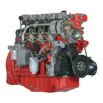
Today, Deutz is one of the best manufacturers of diesel engines for cars, ships, agricultural and construction equipment. Modern technologies, high quality and reliability put
Deutz in line with such world giants as Cummins, Detroit Diesel and others. The range of diesel engines currently produced includes more than 50 models,
different in power and area of application. But all of them are united by one thing — advanced technologies, thanks to which Deutz products are so appreciated in the world.
MWM — Motoren Werke Manheim, formerly known as Deutz Power Systems GmbH, has more than 130 years of successful production of gas and diesel engines. The current product range of this traditional
German company includes engines for various applications with a unit power of 180 to 4000 kW.
The range of engines produced in Mannheim is distinguished by quality, individual technical solutions, reliability and durability. Engines are used in various equipment, both for stationary and
for mobile use: they are compact, lightweight and very economical in fuel consumption.
Created over many years of operation, the database of maintenance and repair manuals issued by the manufacturer allows qualified service of an extensive range of all engine
modifications manufactured by DEUTZ and MWM: 912, 913, 914, 1011, 1012, 1013, 1015, 2008, 2009, 2001 , 2012, 2013, TCD2012, TCD2013, TCD2015, TBD234, TBD616, TCD2016, TBD620,
TCD2020, BVM628, TBD645.
Deutz Engines 912, BF4M2012, F4M2011, BF4M2011, 1011F operators, service and maintenance manuals, error codes list, DTC, spare parts manuals & catalogues, wiring diagrams, schematics free download PDF
![]()
Deutz logo
Deutz engine manuals free download are available for free download.
| Title | File Size | Download Links |
| Deutz 2008-2009 Parts Manual [PDF] | 3.1Mb | Download |
| Deutz 2008-2009 Service Manual [PDF] | 4.4Mb | Download |
| Deutz 226B Operation Manual [PDF] | 8.5Mb | Download |
| Deutz 413 Parts Manual [PDF] | 4.5Mb | Download |
| Deutz Accessories Catalogue [PDF] | 5.2Mb | Download |
| Deutz BF4M1013C Spare Parts Catalogue [PDF] | 3Mb | Download |
| Deutz BFM 1015 Series – BF6M 1015 C, BF8M 1015, BF8M 1015 C, BF8M 1015 CP, BF6M 1015 CP Workshop Manual [PDF] | 12.3Mb | Download |
| Deutz D 2008-2009 Workshop Manual [PDF] | 4.6Mb | Download |
| Deutz D 909 / 910, B / FL 1011 / F / 2011, B / FL 912 / 913 / 914 / C, B / FL 413 F / 513 / C / CP, B / FM 1011 F 2011 Installation Manual [PDF] | 7.8Mb | Download |
| Deutz Engine D2008 2009 Workshop Manual PDF [PDF] | 3.8Mb | Download |
| Deutz Engine Fire Protection – Operation Manual [PDF] | 21.2Mb | Download |
| Deutz Engine S-BV6-8-9M628 Operation Manual [PDF] | 10Mb | Download |
| Deutz FL 411 Service Manual [PDF] | 8.7Mb | Download |
| Deutz FL 413 Service Manual [PDF] | 8.7Mb | Download |
| Deutz Serie 7 Agrotron Service Manual [PDF] | 4.1Mb | Download |
| Gt-50dz Tow Tractor With Deutz Engine [PDF] | 36.1Mb | Download |
Deutz 912
| Title | File Size | Download Links |
| Deutz 912 Parts Manual [PDF] | 4.3Mb | Download |
| Deutz 912 Technical Specifications [PDF] | 384.6kb | Download |
| Deutz 912-913 Repair Manual [PDF] | 5.8Mb | Download |
| Deutz 912-913 Service Manual [PDF] | 2.6Mb | Download |
| Deutz 912-913 Workshop Manual [PDF] | 34.5Mb | Download |
| Deutz F 3 L912 / W, F 4 L912 / W, F 5 L912 / W, B / F6 L912 / W Spare Parts Catalog [PDF] | 15.7Mb | Download |
Deutz 914
| Title | File Size | Download Links |
| Deutz 914 Parts Manual [PDF] | 4.3Mb | Download |
| Deutz 914 Service Manual [PDF] | 2.7Mb | Download |
| Deutz Engine 914 Operation Manual [PDF] | 3.2Mb | Download |
Deutz 1008
| Title | File Size | Download Links |
| Deutz – Workshop Manual BFM 1008F part 1 [PDF] | 2.5Mb | Download |
| Deutz – Workshop Manual BFM 1008F part 2 [PDF] | 2.2Mb | Download |
| Deutz Engines B / FM 1008 / F Workshop Manual [PDF] | 2.7Mb | Download |
Deutz 1011
| Title | File Size | Download Links |
| Deutz 0312 1936 2011 Workshop Manual [PDF] | 20.6Mb | Download |
| Deutz 1011 Parts Manual [PDF] | 1.9Mb | Download |
| Deutz 1011F Workshop Manual [PDF] | 4.7Mb | Download |
| Deutz BF4m1011F Engine Service Parts Manual [PDF] | 4.2Mb | Download |
| Deutz Engine 1011F Werkstatthandbuch [PDF] | 10.3Mb | Download |
| Deutz Engine 1011F Workshop Manual [PDF] | 10.6Mb | Download |
| Deutz Engine B-F L 1011F B-FM 1011F Operation Manual – Engine Description [PDF] | 1.1Mb | Download |
| Deutz Engine B-F L 1011F B-FM 1011F Operation Manual – Engine Operation [PDF] | 157.3kb | Download |
| Deutz Engine B-F L 1011F B-FM 1011F Operation Manual – Engine Preservation [PDF] | 14.2kb | Download |
| Deutz Engine B-F L 1011F B-FM 1011F Operation Manual – Faults, Causes and Remedies [PDF] | 25.1kb | Download |
| Deutz Engine B-F L 1011F B-FM 1011F Operation Manual – General [PDF] | 24.2kb | Download |
| Deutz Engine B-F L 1011F B-FM 1011F Operation Manual – Notes [PDF] | 144.3kb | Download |
| Deutz Engine B-F L 1011F B-FM 1011F Operation Manual – Operating Media [PDF] | 411.2kb | Download |
| Deutz Engine B-F L 1011F B-FM 1011F Operation Manual – Routine Maintenance [PDF] | 299.2kb | Download |
| Deutz Engine B-F L 1011F B-FM 1011F Operation Manual – Service and Maintenance [PDF] | 429.8kb | Download |
| Deutz Engine B-F L 1011F B-FM 1011F Operation Manual – Technical Specifications [PDF] | 53.8kb | Download |
| Deutz Engine B-FL 1011F Operation Manual [PDF] | 2.9Mb | Download |
| Deutz F3M 1011F, BF3M, F4M, BF4M Service Manual [PDF] | 1.3Mb | Download |
Deutz 1012 1013
| Title | File Size | Download Links |
| Deutz 1012 1013 Operation and Maintenance Manual [PDF] | 3.8Mb | Download |
| Deutz 1012-1013 Service Manual [PDF] | 3.6Mb | Download |
| Deutz Engine 1012-1013 Workshop Manual [PDF] | 4.7Mb | Download |
Deutz 1015
| Title | File Size | Download Links |
| Deutz 1015 Maintenance Manual rus [PDF] | 2.8Mb | Download |
| Deutz BFM 1015 Workshop Manual [PDF] | 3.9Mb | Download |
Deutz 2011
| Title | File Size | Download Links |
| Deutz 0312 1936 2011 Workshop Manual- competence level 3 [PDF] | 20.6Mb | Download |
| Deutz 0312 4004 2011 Workshop Manual- competence level 2 [PDF] | 7.5Mb | Download |
| Deutz 2011 – Operation Manual [PDF] | 2.7Mb | Download |
| Deutz D 2011 w, TD 2011 w, TCD 2011 w Workshop Manual- competence level 2 [PDF] | 9.9Mb | Download |
| Deutz D 2011, TD 2011 Workshop Manual- competence level 2 [PDF] | 15.8Mb | Download |
| Deutz Engine B-FL-FM 2011 Operation Manual [PDF] | 7.1Mb | Download |
| Deutz F2M 2011, F3M 2011, F4M 2011, BF3M 2011, BF4M 2011, BF3L 2011, BF4L 2011 F2L 2011, F3L 2011, F4L 2011 Operation Manual [PDF] | 5.2Mb | Download |
| Deutz F4M 2011 Technical Specifications [PDF] | 278.7kb | Download |
| Deutz F4M2011 Service Manual pdf [PDF] | 5.2Mb | Download |
Deutz 2012
| Title | File Size | Download Links |
| Deutz 2012 Service Manual [PDF] | 9.5Mb | Download |
| Deutz BF4M 2012 Operation Manual [PDF] | 4.6Mb | Download |
| Deutz BF4M2012 Workshop Manual [PDF] | 14.3Mb | Download |
| Deutz Engine 2012 Operation Manual [PDF] | 3.7Mb | Download |
| Deutz Engine BF6M 1013 Operation Manual [PDF] | 3.3Mb | Download |
| Deutz Engine BFM-2012 Workshop Manual [PDF] | 8.7Mb | Download |
Deutz TCD 2012
| Title | File Size | Download Links |
| Deutz TCD 2012-2013 Service Manual [PDF] | 3.9Mb | Download |
| Deutz TCD2012 Instruction Manual [PDF] | 5.1Mb | Download |
Deutz TCD 2013
| Title | File Size | Download Links |
| Deutz Engine TCD 2013 2V Workshop Manual [PDF] | 26.9Mb | Download |
| Deutz Engine TCD 2013 L04-06 4V Instruction Manual – Care and maintenance work [PDF] | 1017.5kb | Download |
| Engine corrosion protection [PDF] | 119kb | Download |
| Engine Description [PDF] | 2.1Mb | Download |
| Faults, causes, and remedies [PDF] | 79.7kb | Download |
| General [PDF] | 13.1kb | Download |
| Maintenance [PDF] | 493.5kb | Download |
| Operating substances [PDF] | 44.7kb | Download |
| Operation Manual [PDF] | 15.6kb | Download |
| Operation [PDF] | 151.7kb | Download |
| Service [PDF] | 22.5kb | Download |
| Technical data [PDF] | 72.2kb | Download |
| Deutz TCD 2013 4V – Industry Workshop Manual [PDF] | 535.7kb | Download |
Deutz Engine TCD 2015 Service Manual
| Title | File Size | Download Links |
| General [PDF] | 18.1kb | Download |
| Job card overview [PDF] | 20.3Mb | Download |
| Special tools [PDF] | 299.3kb | Download |
| Standard tools [PDF] | 93.2kb | Download |
| Technical data [PDF] | 185.4kb | Download |
| User notes [PDF] | 51.8kb | Download |
| Deutz TCD 2015 Service Manual [PDF] | 3.2Mb | Download |
Deutz Engines
Modern technologies and materials, top quality, dependability, durability, and longevity are all features of Deutz diesel engines manufactured in Germany. German brand engines have high specific power and torque at the lightest possible weight for power plants with such specs. As a result, Deutz engines, which use the company’s unique innovations, can function well even in the most adverse circumstances and at a high maximum load for extended periods without diminishing motor resources or increasing overhaul time, therefore saving operational expenses.
After years of research at the company’s scientific and design bureaus, Deutz engineers developed motors that balance low operating costs and little impact on the environment. Because of their low fuel consumption, power plants from the German company Deutz are among the most cost effective in the world per kilowatt-hour produced, and they conform to the strictest standards for environmental protection. This means you may save money on gasoline and put Deutz generator installations close to where people live and work.
The Deutz 413 Series consists of V-shaped (V-Twin) diesel engines with 6, 8, 10, or 12 cylinders, a horizontal selection shaft, and valves in the upper location (OHV) for use in industrial and domestic applications. Focused on usage in sub-zero temperatures (down to -30 degrees Celsius), the 137 hp. (100 kW) to 322 hp. (236 kW) range of power and forced air conditioning;
Four-stroke, overhead-valve (OHV), horizontal power-shaft (HPS), and forced-air-cooled (FAC.) Deutz 912 Series diesel engines are designed for typical circumstances and may produce anywhere from 47 horsepower (34 kilowatts) to 111 horsepower (70 kW) (82 kW). The W models have a two-stage fuel combustion mechanism;
The Deutz 913 Series consists of 4-stroke, 3, 4, and 6-cylinder diesel engines with OHV, a horizontal power shaft, and forced air cooling, designed for use in typical circumstances and ranging in output from 59 horsepower (44 kilowatts) to 191 horsepower (141 kilowatts);
The Deutz 914 Series consists of four-stroke, three-, four-, five-, and six-cylinder diesel engines designed for professional and household appliances, featuring overhead valves, a horizontal power shaft, and forced air cooling, and optimized for normal conditions of operation between 59 horsepower (44 kilowatts) and 189 horsepower (141 kilowatts);
The Deutz 912/914 Genset Series includes 19 hp (14 kW) to 97.9 hp (4-stroke, 2, 3, 4, 6, 6-cylinder, OHV, horizontal air-cooled shaft, air-cooled) diesel engines for electro generators designed for usage in normal and harsh climatic situations (73 kW) manufactured with a mechanical or electronic (optional) fuel supply regulator;
The Deutz 1008 Series is a line of four-stroke, 2, 3, and 4-cylinder diesel engines designed for use in construction machinery, featuring overhead valves (OHV), a horizontal power shaft, liquid cooling, and an emphasis on operating in harsh environments, with outputs ranging from 17.7 horsepower (13 kilowatts) to 42 horsepower (31 kilowatts).
The Deutz 1011 Series is a line of 30-liter, 4-stroke, 2-, 3-, and 4-cylinder diesel engines used in construction machinery. These engines have overhead valves (OHV), a horizontal power shaft, and liquid cooling and are optimized for usage in harsh climates. (22 kW) up to (89.5 hp) (61 kW). Gas emission regulations that are in line with those of the European Union’s STEP II and the United States CFR 40, part 89, Tier II;
The Deutz 1013 Series consists of 4-stroke, 4- and 6-cylinder diesel engines with OHV, the horizontal power shaft, liquid cooling, and an output range of 154 hp (115 kW) to 313 hp (233 kW) for use in industrial and construction equipment in both mild and severe climates.
The Deutz 1015 Series consists of 6- and 8-cylinder V-shaped diesel engines with OHV, a horizontal power shaft, liquid cooling, and an output range of 407 hp (300 kW) to 598 hp (440 kW) that are designed for usage in typical climates.
The Deutz 1013/1015 Genset Series consists of four-stroke, six- and eight-cylinder diesel engines for electric generators, with overhead valves (OHV), a horizontal power shaft, liquid cooling, and an output ranging from 103 horsepower (77 kilowatts) to 571 horsepower (362 kilowatts) (426 kW) produced using both a mechanical regulator and electronic control (as an extra);
With power ranging from 31 horsepower (23 kilowatts) to 88 horsepower (65 kilowatts), the Deutz 2011 Series consists of 2, 3, 4, and 4-cylinder diesel engines for mobile medium-power mobile equipment with OHV, horizontal power shaft, air or liquid cooling, and an emphasis on operation in normal climatic conditions; the L models feature a heat exchanger.
The Deutz TCD 2011 Series is a line of air-cooled, OHV, horizontally-mounted, 2- and 3-cylinder diesel engines for medium-power mobile equipment ranging in output from 31 to 100 horsepower (23 to 74 kilowatts) (74.9 kW). Meet the gas emission requirements of European Union (EU) STEP III and United States (US) Tier 3;
Deutz f4m2011
The Deutz 2012 Series is a line of four- and six-cylinder diesel engines designed for medium-power mobile equipment. They feature overhead valves (OHV), a horizontal power shaft, and liquid cooling and are optimized for use in typical climates. Their output ranges from 101.8 horsepower (74.9 kilowatts) to 210 horsepower (155 kilowatts).
The Deutz TCD 2012 Series is a four-stroke and six-cylinder diesel engine line designed for medium-power mobile equipment. They feature overhead valves (OHV), a horizontal power shaft, and liquid cooling and are optimized for use in temperate climates.
The Deutz 2011/2012 Genset Series consists of four-stroke 2, 3, and 4-cylinder diesel engines for electric generators with overhead valves, horizontal power shafts, liquid or air cooling, and a primary focus on operation in both normal and difficult climatic conditions, with outputs ranging from 15.5 horsepower (11.4 kilowatts) to 101 horsepower (75 kilowatts);
The Deutz TCD2013 Series is a line of four- and six-cylinder diesel engines designed for use in mobile medium-power equipment. These engines feature overhead valves (OHV), a horizontal power shaft, liquid cooling, and are optimized for use in temperate climates. Their output ranges from 173 horsepower (129 kilowatts) to 325.9 horsepower (243 kW). Meet the requirements for gas emissions set out by the European Union’s STEP III A and the United States’ Tier 3;
The Deutz TCD2013 Genset Series consists of four- and six-cylinder diesel engines with an output ranging from 121 horsepower (90 kilowatts) to 314 horsepower (234 kilowatts) with an emphasis on normal climate operating.
The Deutz TCD 2015 Series consists of 6 and 8-cylinder, OHV, the horizontal power shaft, liquid-cooled, industrial diesel engines designed for usage in typical climates and capable of producing between 489 horsepower (360 kilowatts) and 670 horsepower (500 kilowatts);
The Deutz TCD 2.9-16 liter Series consists of 4, 6, and 8-cylinder diesel engines for mobile equipment; their engine volumes range from 2.9 to 16 liters; they feature overhead valves (OHV), a horizontal power shaft, water cooling, and are optimized for use in extreme climates; their outputs range from 50 horsepower (36.9 kW) to 697 horsepower (600 lb-ft) (520 kW).

![]()
Deutz 2008-2009 Service Manual
Deutz 2008-2009 Service Manual
Deutz 2008-2009 Service Manual_compresse
Adobe Acrobat Document
4.2 MB
![]()
Deutz FL 411 Service Manual
Deutz FL 411 Service Manual
Deutz FL 411 Service Manual_compressed.p
Adobe Acrobat Document
3.1 MB
![]()
Deutz Engine S-BV6-8-9M628 Operation Manual
Deutz Engine S-BV6-8-9M628 Operation Manual
Deutz Engine S-BV6-8-9M628 Operation Man
Adobe Acrobat Document
5.2 MB
![]()
Deutz 226B Operation Manual
Deutz 226B Operation Manual
Deutz 226B Operation Manual_compressed.p
Adobe Acrobat Document
2.2 MB
![]()
Deutz FL 413 Service Manual
Deutz FL 413 Service Manual
Deutz FL 413 Service Manual_compressed.p
Adobe Acrobat Document
3.1 MB
![]()
Deutz Serie 7 Agrotron Service Manual
Deutz Serie 7 Agrotron Service Manual
Deutz Serie 7 Agrotron Service Manual_co
Adobe Acrobat Document
3.6 MB
![]()
Gt-50dz Tow Tractor With Deutz Engine
Gt-50dz Tow Tractor With Deutz Engine
Gt-50dz Tow Tractor With Deutz Engine_co
Adobe Acrobat Document
23.7 MB
![]()
Deutz 1011 Parts Manual
Deutz 1011 Parts Manual
Deutz 1011 Parts Manual_compressed.pdf
Adobe Acrobat Document
1.7 MB
![]()
Deutz 2008-2009 Parts Manual
Deutz 2008-2009 Parts Manual
Deutz 2008-2009 Parts Manual_compressed.
Adobe Acrobat Document
2.2 MB
![]()
Deutz 413 Parts Manual
Deutz 413 Parts Manual
Deutz 413 Parts Manual_compressed.pdf
Adobe Acrobat Document
2.6 MB
![]()
Deutz 912 Parts Manual
Deutz 912 Parts Manual
Deutz 912 Parts Manual_compressed.pdf
Adobe Acrobat Document
2.4 MB
![]()
Deutz 914 Parts Manual
Deutz 914 Parts Manual
Deutz 914 Parts Manual_compressed.pdf
Adobe Acrobat Document
2.9 MB
![]()
Deutz Accessories Catalogue
Deutz Accessories Catalogue
Deutz Accessories Catalogue_compressed.p
Adobe Acrobat Document
666.4 KB
![]()
Deutz BF4M1013C Spare Parts Catalogue
Deutz BF4M1013C Spare Parts Catalogue
Deutz BF4M1013C Spare Parts Catalogue_co
Adobe Acrobat Document
1.7 MB
![]()
Deutz 912-913 Service Manual
Deutz 912-913 Service Manual
Deutz 912-913 Service Manual_compressed.
Adobe Acrobat Document
2.4 MB
![]()
Deutz 912-913 Workshop Manual Workshop Manual
Deutz 912-913 Workshop Manual Workshop Manual
Deutz 912-913 Workshop Manual Workshop
Adobe Acrobat Document
4.9 MB
![]()
Deutz 912-913 Workshop Manual
Deutz 912-913 Workshop Manual
Deutz 912-913 Workshop Manual_compressed
Adobe Acrobat Document
8.2 MB
![]()
Deutz 914 Service Manual
Deutz 914 Service Manual
Deutz 914 Service Manual_compressed.pdf
Adobe Acrobat Document
2.6 MB
![]()
Deutz — Workshop Manual BFM 1008F
Deutz — Workshop Manual BFM 1008F
Deutz — Workshop Manual BFM 1008F part 1
Adobe Acrobat Document
1.5 MB
![]()
Deutz 0312 1936 2011 Workshop Manual
Deutz 0312 1936 2011 Workshop Manual
Deutz 0312 1936 2011 Workshop Manual_com
Adobe Acrobat Document
17.3 MB
![]()
Deutz 1011F Workshop Manual
Deutz 1011F Workshop Manual
Deutz 1011F Workshop Manual_compressed.p
Adobe Acrobat Document
3.6 MB
![]()
Deutz Engine 1011F Werkstatthandbuch
Deutz Engine 1011F Werkstatthandbuch
Deutz Engine 1011F Werkstatthandbuch_com
Adobe Acrobat Document
10.1 MB
![]()
Deutz Engine B-F L 1011F B-FM 1011F Operation Manual — Engine Description
Deutz Engine B-F L 1011F B-FM 1011F Operation Manual — Engine Description
Deutz Engine B-F L 1011F B-FM 1011F Oper
Adobe Acrobat Document
1.1 MB
![]()
Deutz Engine B-F L 1011F B-FM 1011F Operation Manual — Engine Operation
Deutz Engine B-F L 1011F B-FM 1011F Operation Manual — Engine Operation
Deutz Engine B-F L 1011F B-FM 1011F Oper
Adobe Acrobat Document
143.3 KB
![]()
Deutz Engine B-F L 1011F B-FM 1011F Operation Manual — Faults, Causes and Remedies
Deutz Engine B-F L 1011F B-FM 1011F Operation Manual — Faults, Causes and Remedies
Deutz Engine B-F L 1011F B-FM 1011F Oper
Adobe Acrobat Document
20.2 KB
![]()
Deutz F3M 1011F, BF3M, F4M, BF4M Service Manual
Deutz F3M 1011F, BF3M, F4M, BF4M Service Manual
Deutz F3M 1011F, BF3M, F4M, BF4M Service
Adobe Acrobat Document
894.8 KB
![]()
Deutz 1012 1013 Operation and Maintenance Manual
Deutz 1012 1013 Operation and Maintenance Manual
Deutz 1012 1013 Operation and Maintenanc
Adobe Acrobat Document
3.1 MB
![]()
Deutz 1012-1013 Service Manual
Deutz 1012-1013 Service Manual
Deutz 1012-1013 Service Manual_compresse
Adobe Acrobat Document
3.1 MB
![]()
Deutz Engine 1012-1013 Workshop Manual
Deutz Engine 1012-1013 Workshop Manual
Deutz Engine 1012-1013 Workshop Manual_c
Adobe Acrobat Document
4.2 MB
![]()
Deutz BFM 1015 Workshop Manual
Deutz BFM 1015 Workshop Manual
Deutz BFM 1015 Workshop Manual_compresse
Adobe Acrobat Document
3.6 MB
![]()
Deutz 0312 1936 2011 Workshop Manual
Deutz 0312 1936 2011 Workshop Manual
Deutz 0312 1936 2011 Workshop Manual- co
Adobe Acrobat Document
17.3 MB
![]()
Deutz Engine B-FL-FM 2011 Operation Manual
Deutz Engine B-FL-FM 2011 Operation Manual
Deutz Engine B-FL-FM 2011 Operation Manu
Adobe Acrobat Document
4.8 MB
![]()
Deutz 2012 Service Manual
Deutz 2012 Service Manual
Deutz 2012 Service Manual_compressed.pdf
Adobe Acrobat Document
4.6 MB
![]()
Deutz Engine 2012 Operation Manual
Deutz Engine 2012 Operation Manual
Deutz Engine 2012 Operation Manual_compr
Adobe Acrobat Document
942.0 KB
![]()
Deutz Engine BF6M 1013 Operation Manual
Deutz Engine BF6M 1013 Operation Manual
Deutz Engine BF6M 1013 Operation Manual_
Adobe Acrobat Document
3.0 MB
![]()
Deutz Engine TCD 2013 L04-06 4V Instruction Manual — Faults, causes and remedies
Deutz Engine TCD 2013 L04-06 4V Instruction Manual — Faults, causes and remedies
Deutz Engine TCD 2013 L04-06 4V Instruct
Adobe Acrobat Document
74.2 KB
![]()
Deutz Engine TCD 2013 L04-06 4V Instruction Manual
Deutz Engine TCD 2013 L04-06 4V Instruction Manual
Deutz Engine TCD 2013 L04-06 4V Instruct
Adobe Acrobat Document
140.2 KB
![]()
Deutz Engine TCD 2015 Workshop Manual
Deutz Engine TCD 2015 Workshop Manual
Deutz Engine TCD 2015 Workshop Manual —
Adobe Acrobat Document
14.3 KB
![]()
Deutz Engine TCD 2015 Workshop Manual
Deutz Engine TCD 2015 Workshop Manual
Deutz Engine TCD 2015 Workshop Manual —
Adobe Acrobat Document
77.8 KB
![]()
Deutz Engine TCD 2015 Workshop Manual
Deutz Engine TCD 2015 Workshop Manual
Deutz Engine TCD 2015 Workshop Manual —
Adobe Acrobat Document
47.9 KB
![]()
Deutz TCD 2015 Service Manual
Deutz TCD 2015 Service Manual
Deutz TCD 2015 Service Manual_compressed
Adobe Acrobat Document
2.5 MB
![]()
Deutz — Workshop Manual BFM
Deutz — Workshop Manual BFM
Deutz — Workshop Manual BFM 1008F part 2
Adobe Acrobat Document
2.2 MB
Deutz
The German company Deutz was created by designer Nikolaus Otto and businessman Eugen Longen. At the time of the organization, Otto had already created his internal
combustion engine, Longen helped him get a patent and conducted an advertising campaign. Three years later, the model at the Paris exhibition received a gold medal, it was a worthy alternative to
bulky and dangerous steam engines.
In 1869, in the suburbs of Cologne, partners launched a motor factory. Otto managed to improve his development, and he proposed to the world the
first Deutz four-stroke engine, in which the principle of compression of the fuel-air mixture was used before ignition. Then, together with Robert Bosch, he developed an electric ignition
system.
In subsequent years, the production of engines, spare parts and parts for them was led by legendary personalities: Gottlieb Daimler, Wilhelm Maybach, collaborated
with the company «motor genius» Rudolf Diesel and the creator of the famous car Ettore Bugatti. Since its birth, Deutz has made a significant contribution to the history of the world engine
industry.
In 1949, Deutz production was expanded. The range of motor products was supplemented by agricultural and construction equipment — tractors, trucks and dump trucks
equipped with air-cooled diesel engines. In 1975, Iveco bought the automobile production, Deutz retained the production of motors and tractors, noting in 1978 the manufacture of a 4 millionth
internal combustion engine.
The agricultural machinery production line was sold by the company to the Italian Same Group in 1995, and Deutz returned to its origins — the production of engines
for various purposes, including for power plants.
Today, Deutz employs more than 6,000 employees, of which more than 1,500 are in other countries. The corporation includes 22 factories producing power plants for
various purposes, spare parts for them and some consumables. This business activity provides the company with an annual turnover of more than 1.3 billion euros. Sale of engines, their
maintenance, warranty and post-warranty repairs are carried out in 130 countries.

Werkstatthandbuch
Справочник по ремонту
П Р Е Д И С Л О В И Е
Квалифицированное исполнение ремонтно-наладочных работ является непременным условием надежной работы двигателя.
В настоящем справочнике описаны рабочие операции по выполнению ремонтноналадочных работ на двигателе и его узлах. При этом предполагается, что эти работы выполняются специальным высококвалифицированным персоналом.
При составлении настоящего справочника, в целях облегчения понимания, краткий описательный текст снабжен условными обозначениями, наглядно иллюстрирующими описываемую рабочую операцию.
Вопросыэксплуатацииитехническогообслуживаниярассматриваютсявсоответствующей инструкции по эксплуатации.
Дляоформлениязаказаназапчастинеобходимопользоватьсясоответствующимсписком запчастей.
Внесение изменений в настоящий справочник не предусматривается. Изменения будут внесены в новое издание справочника.
Во время ремонта необходимо учитывать указания наших технических циркуляров.
Общие указания:
—Внимательно прочтите и выполняйте указания, изложенные в настоящем справочнике. Это поможет Вам избежать несчастныхслучаев и обеспечить надежную и безотказную эксплуатацию двигателя.
—Все, кто участвует в ремонтно-наладочных работах, должны иметь доступ к справочнику и понимать его содержание.
—Несоблюдение настоящей инструкции по ремонту может привести к неполадкамвработеиповреждениюдвигателя,атакжектравмамперсонала, за которые изготовитель не несет ответственности.
—Необходимособлюдатьсоответствующиепредписанияпопредупреждению несчастных случаев, а также прочие общепризнанные правила техники безопасности и охраны труда.
—Непременным условием качественного ремонта является наличие всего необходимого оборудования, ручного и специального инструмента, а также их безупречное состояние.
—Высокая экономичность, надежность и длительный срок службы возможны только при применении подлинных деталей фирмы «ДОЙТЦ СЕРВИС ИНТЕРНАТИОНАЛЬ ГмбХ».
—Такие детали двигателя, как пружины, скобы, упругие стопорные кольца и т.д., являются источником повышенной опасности при неправильном обращении с ними.
—Ремонт двигателя должен соответствовать его назначению, указанному изготовителем. При переделках можно использовать только те детали, которые разрешает «ДОЙТЦ СЕРВИС ИНТЕРНАТИОНАЛЬ ГмбХ» для данной цели применения.

Werkstatthandbuch
|
Справочник по ремонту |
|
|
Workshop Manual |
BFM 1015 |
0297 7467
Gegenüber Darstellungen und Angaben dieses Werkstatthandbuches sind technische Änderungen, die zur Verbesserung der Motoren notwendig werden, vorbehalten. Nachdruck und Vervielfältigung jeglicher Art, auch auszugsweise, bedarf unserer schriftlichen Genehmigung.
Фирма оставляет за собой право вносить в иллюстрации и текст изменения технического характера, необходимые для усовершенствования двигателя. Перепечатка и любое размножение, в том числе частичное, допускается только с нашего письменного разрешения.
In view of continuous design improvements or changes, the technical sp e- cifications and the illustrations shown in this Workshop Manual are subject to alteration. Reprinting and reproduction, in part or in whole, are subject to our written approval.

Service-Telefon für technische Rückfragen
Сервисный телефон для выяснения технических вопросов
Service telephone for technical enquiries
(0221) 822 5454
Von 08.00 bis 17.00 Uhr mit direkter Vermittlung. Nachts, an Wochenenden und an Feiertagen als Anrufbeantworter
(Wir reagieren am nächsten Arbeitstag).
C 8.00 до 17.00 прямая связь.
Ночью, по выходным и праздничным дням через автоответчик (мы ответим в следующий рабочий день)
Personal answering service from 8.00 a.m. to 5.00 p.m.
At all other times and on weekends and holidays an ansafone system operates (we call back the next working day).
V O R W O R T
Die sachgerechte Ausführung von Reparaturund Einstellarbeiten ist Voraussetzung für einen zuverlässigen Motorbetrieb.
In diesem Werkstatthandbuch sind die zweckmäßigen Arbeitsabläufe für anfallende Reparaturund Einstellarbeiten an Motor und Motorbauteilen beschrieben. Dabei wird vorausgesetzt, daß die Arbeiten von qualifiziertem Fachpersonal durchgeführt werden.
Bei der Gestaltung des Werkstatthandbuches wurden im Sinne einer schnellen Erfassung der Inhalte zusätzlich zu den knapp gehaltenen beschreibenden Texten Bildzeichen gesetzt, die den jeweils behandelten Arbeitsgang visualisieren.
Betriebsund Wartungshinweise sind der entsprechenden Betriebsanleitung zu entnehmen.
Zur Ersatzteilbestellung ist die jeweilige Ersatzteilliste zugrunde zu legen.
Das vorliegende Werkstatthandbuch unterliegt keinem Änderungsdienst. Änderungen werden jeweils bei Neuauflage eingearbeitet.
Beachten Sie bei Reparaturen die Hinweise unserer Technischen Rundschreiben.
Allgemeine Hinweise:
—Lesen und beachten Sie die Informationen dieses Werkstatthandbuches. Sie vermeiden Unfälle und verfügen über einen funktionstüchtigen und einsatzbereiten Motor.
—Stellen Sie sicher, daß dieses Werkstatthandbuch jedem an Reparaturoder Einstellarbeiten Beteiligten zur Verfügung steht und daß der Inhalt verstanden wird.
—Die Nichtbeachtung dieser Reparaturanleitung kann zu Funktionsstörungen und Motorschäden sowie Verletzungen von Personen führen, für die vom Hersteller keine Haftung übernommen wird.
—Die einschlägigen Unfallverhütungsvorschriften sowie die sonstigen allgemeinen anerkannten sicherheitstechnischen und arbeitsmedizinischen Regeln sind einzuhalten.
—Voraussetzung für die fachgerechte Reparatur ist die Verfügbarkeit aller erforderlichen Ausrüstungen, Handund Spezialwerkzeuge, sowie deren einwandfreier Zustand.
—Höchste Wirtschaftlichkeit, Zuverlässigkeit und lange Lebensdauer ist nur bei
Verwendung von Original Teilen der DEUTZ AG sichergestellt.
—Motorteile wie Federn, Klammern, elastische Halteringe etc. beinhalten bei unsachgemäßer Behandlung erhöhte Verletzungsgefahr.
—Die Instandsetzung des Motors muß der bestimmungsgemäßen Verwendung — definiert durch den Gerätehersteller — entsprechen. Bei Umbauten dürfen nur von der DEUTZ AG für den jeweiligen Verwendungszweck freigegebene Teile eingesetzt werden.
П Р Е Д И С Л О В И Е
Квалифицированное исполнение ремонтно-наладочных работ является непременным условием надежной работы двигателя.
В настоящем справочнике описаны рабочие операции по выполнению ремонтноналадочных работ на двигателе и его узлах. При этом предполагается, что эти работы выполняются специальным высококвалифицированным персоналом.
При составлении настоящего справочника, в целях облегчения понимания, краткий описательный текст снабжен условными обозначениями, наглядно иллюстрирующими описываемую рабочую операцию.
Вопросыэксплуатацииитехническогообслуживаниярассматриваютсявсоответствующей инструкции по эксплуатации.
Дляоформлениязаказаназапчастинеобходимопользоватьсясоответствующимсписком запчастей.
Внесение изменений в настоящий справочник не предусматривается. Изменения будут внесены в новое издание справочника.
Во время ремонта необходимо учитывать указания наших технических циркуляров.
Общие указания:
—Внимательно прочтите и выполняйте указания, изложенные в настоящем справочнике. Это поможет Вам избежать несчастныхслучаев и обеспечить надежную и безотказную эксплуатацию двигателя.
—Все, кто участвует в ремонтно-наладочных работах, должны иметь доступ к справочнику и понимать его содержание.
—Несоблюдение настоящей инструкции по ремонту может привести к неполадкамвработеиповреждениюдвигателя,атакжектравмамперсонала, за которые изготовитель не несет ответственности.
—Необходимособлюдатьсоответствующиепредписанияпопредупреждению несчастных случаев, а также прочие общепризнанные правила техники безопасности и охраны труда.
—Непременным условием качественного ремонта является наличие всего необходимого оборудования, ручного и специального инструмента, а также их безупречное состояние.
—Высокая экономичность, надежность и длительный срок службы возможны только при применении подлинных деталей фирмы «ДОЙТЦ СЕРВИС ИНТЕРНАТИОНАЛЬ ГмбХ».
—Такие детали двигателя, как пружины, скобы, упругие стопорные кольца и т.д., являются источником повышенной опасности при неправильном обращении с ними.
—Ремонт двигателя должен соответствовать его назначению, указанному изготовителем. При переделках можно использовать только те детали, которые разрешает «ДОЙТЦ СЕРВИС ИНТЕРНАТИОНАЛЬ ГмбХ» для данной цели применения.
F O R E W O R D
Reliable engine operation is dependent on properly executed repairs as well as adjustment work.
This Workshop Manual describes the appropriate operations for any repair and adjustment work on the engine and engine components. It is presumed that this work will be carried out by qualified personnel.
The Manual has been laid out to ensure quick comprehension of the contents, i. e illustrations have been placed adjacent to the brief text passages to clearly show the working operations.
Aspects of operation and maintenance are dealt with in the respective Operation Manual.
For spare parts orders the respective spare parts catalogue should be referred to.
This Workshop Manual is not subject to engineering change service and is valid until next issue.
Therefore please refer to the information in our Technical Circulars when carrying out repairs.
General information:
—Please read carefully and observe the instructions given in this Workshop Manual to avoid accidents and ensure that your engine always functions properly and reliably.
—Make sure that this Workshop Manual is readily available for all those carrying out repairs or adjustments and that the contents are well understood.
—Non-compliance with these repair instructions may result in malfunction and engine damage as well as personal injuries for which the manufacturer shall not accept any liability.
—The accident prevention regulations and all other generally recognized regulations on safety and occupational medicine are to be observed.
—A prerequisite for successful repair is that all required equipment, hand and special tools are available and in perfect working order.
—Optimal operation economy, reliability and durability of the engine can only be ensured when genuine parts of DEUTZ AG are used.
—Engine components such as springs, clamps, snap rings, etc. may cause injury if not handled with care.
—Engine repairs must be carried out in accordance with intended use as defined by the equipment manufacturer. For conversions, only parts approved by DEUTZ AG for a specific purpose should be used.
П Р Е Д И С Л О В И Е
Квалифицированное исполнение ремонтно-наладочных работ является непременным условием надежной работы двигателя.
В настоящем справочнике описаны рабочие операции по выполнению ремонтноналадочных работ на двигателе и его узлах. При этом предполагается, что эти работы выполняются специальным высококвалифицированным персоналом.
При составлении настоящего справочника, в целях облегчения понимания, краткий описательный текст снабжен условными обозначениями, наглядно иллюстрирующими описываемую рабочую операцию.
Вопросыэксплуатацииитехническогообслуживаниярассматриваютсявсоответствующей инструкции по эксплуатации.
Дляоформлениязаказаназапчастинеобходимопользоватьсясоответствующимсписком запчастей.
Внесение изменений в настоящий справочник не предусматривается. Изменения будут внесены в новое издание справочника.
Во время ремонта необходимо учитывать указания наших технических циркуляров.
Общие указания:
—Внимательно прочтите и выполняйте указания, изложенные в настоящем справочнике. Это поможет Вам избежать несчастныхслучаев и обеспечить надежную и безотказную эксплуатацию двигателя.
—Все, кто участвует в ремонтно-наладочных работах, должны иметь доступ к справочнику и понимать его содержание.
—Несоблюдение настоящей инструкции по ремонту может привести к неполадкамвработеиповреждениюдвигателя,атакжектравмамперсонала, за которые изготовитель не несет ответственности.
—Необходимособлюдатьсоответствующиепредписанияпопредупреждению несчастных случаев, а также прочие общепризнанные правила техники безопасности и охраны труда.
—Непременным условием качественного ремонта является наличие всего необходимого оборудования, ручного и специального инструмента, а также их безупречное состояние.
—Высокая экономичность, надежность и длительный срок службы возможны только при применении подлинных деталей фирмы «ДОЙТЦ СЕРВИС ИНТЕРНАТИОНАЛЬ ГмбХ».
—Такие детали двигателя, как пружины, скобы, упругие стопорные кольца и т.д., являются источником повышенной опасности при неправильном обращении с ними.
—Ремонт двигателя должен соответствовать его назначению, указанному изготовителем. При переделках можно использовать только те детали, которые разрешает «ДОЙТЦ СЕРВИС ИНТЕРНАТИОНАЛЬ ГмбХ» для данной цели применения.

Inhalts-Verzeichnis
Содержание
Table of Contents
Technische Daten / Bildzeichenerklärung
Технические данные / Объяснение условных обозначений
Specification data / Key to symbols
1
Prüfen und Einstellen
Контроль и регудировка
Checking and adjusting
2
Bauteile instand setzen
Ремонт узлов
Repair of components
3
Demontage und Montage, Motor komplett
Разборка и сборка, двигатель в сборе
Disassembly and reassembly of complete engine
4
Werkzeuge
Инструмент
Tools
5
П Р Е Д И С Л О В И Е
Квалифицированное исполнение ремонтно-наладочных работ является непременным условием надежной работы двигателя.
В настоящем справочнике описаны рабочие операции по выполнению ремонтноналадочных работ на двигателе и его узлах. При этом предполагается, что эти работы выполняются специальным высококвалифицированным персоналом.
При составлении настоящего справочника, в целях облегчения понимания, краткий описательный текст снабжен условными обозначениями, наглядно иллюстрирующими описываемую рабочую операцию.
Вопросыэксплуатацииитехническогообслуживаниярассматриваютсявсоответствующей инструкции по эксплуатации.
Дляоформлениязаказаназапчастинеобходимопользоватьсясоответствующимсписком запчастей.
Внесение изменений в настоящий справочник не предусматривается. Изменения будут внесены в новое издание справочника.
Во время ремонта необходимо учитывать указания наших технических циркуляров.
Общие указания:
—Внимательно прочтите и выполняйте указания, изложенные в настоящем справочнике. Это поможет Вам избежать несчастныхслучаев и обеспечить надежную и безотказную эксплуатацию двигателя.
—Все, кто участвует в ремонтно-наладочных работах, должны иметь доступ к справочнику и понимать его содержание.
—Несоблюдение настоящей инструкции по ремонту может привести к неполадкамвработеиповреждениюдвигателя,атакжектравмамперсонала, за которые изготовитель не несет ответственности.
—Необходимособлюдатьсоответствующиепредписанияпопредупреждению несчастных случаев, а также прочие общепризнанные правила техники безопасности и охраны труда.
—Непременным условием качественного ремонта является наличие всего необходимого оборудования, ручного и специального инструмента, а также их безупречное состояние.
—Высокая экономичность, надежность и длительный срок службы возможны только при применении подлинных деталей фирмы «ДОЙТЦ СЕРВИС ИНТЕРНАТИОНАЛЬ ГмбХ».
—Такие детали двигателя, как пружины, скобы, упругие стопорные кольца и т.д., являются источником повышенной опасности при неправильном обращении с ними.
—Ремонт двигателя должен соответствовать его назначению, указанному изготовителем. При переделках можно использовать только те детали, которые разрешает «ДОЙТЦ СЕРВИС ИНТЕРНАТИОНАЛЬ ГмбХ» для данной цели применения.
![]()
Technische Daten
Технические данные |
|
Specification data |
BFM 1015 |
Hinweis zum Gebrauch des Werkstatthandbuches
In diesem Werkstatthandbuch sind alle technischen Daten, Einstellwer te und
Anziehvorschriften den Stellen zugeordnet, wo sie bei Servicearbeiten, Deund
Montage am Motor benötigt werden.
Указания по пользованию справочником по ремонту и техобслуживанию:
В настоящем справочнике все технические данные, величины регулируемых параметров и предписания по затяжке приведены в тех местах, где они требуются при сервисных работах, разборке и сборке двигателя.
Notes for the user of this Workshop Manual
In this Workshop Manual all specification data, adjustment values and tightening specifications are allocated to those parts where they are needed for service work, disassembly and reassembly on the engine.
П Р Е Д И С Л О В И Е
Квалифицированное исполнение ремонтно-наладочных работ является непременным условием надежной работы двигателя.
В настоящем справочнике описаны рабочие операции по выполнению ремонтноналадочных работ на двигателе и его узлах. При этом предполагается, что эти работы выполняются специальным высококвалифицированным персоналом.
При составлении настоящего справочника, в целях облегчения понимания, краткий описательный текст снабжен условными обозначениями, наглядно иллюстрирующими описываемую рабочую операцию.
Вопросыэксплуатацииитехническогообслуживаниярассматриваютсявсоответствующей инструкции по эксплуатации.
Дляоформлениязаказаназапчастинеобходимопользоватьсясоответствующимсписком запчастей.
Внесение изменений в настоящий справочник не предусматривается. Изменения будут внесены в новое издание справочника.
Во время ремонта необходимо учитывать указания наших технических циркуляров.
Общие указания:
—Внимательно прочтите и выполняйте указания, изложенные в настоящем справочнике. Это поможет Вам избежать несчастныхслучаев и обеспечить надежную и безотказную эксплуатацию двигателя.
—Все, кто участвует в ремонтно-наладочных работах, должны иметь доступ к справочнику и понимать его содержание.
—Несоблюдение настоящей инструкции по ремонту может привести к неполадкамвработеиповреждениюдвигателя,атакжектравмамперсонала, за которые изготовитель не несет ответственности.
—Необходимособлюдатьсоответствующиепредписанияпопредупреждению несчастных случаев, а также прочие общепризнанные правила техники безопасности и охраны труда.
—Непременным условием качественного ремонта является наличие всего необходимого оборудования, ручного и специального инструмента, а также их безупречное состояние.
—Высокая экономичность, надежность и длительный срок службы возможны только при применении подлинных деталей фирмы «ДОЙТЦ СЕРВИС ИНТЕРНАТИОНАЛЬ ГмбХ».
—Такие детали двигателя, как пружины, скобы, упругие стопорные кольца и т.д., являются источником повышенной опасности при неправильном обращении с ними.
—Ремонт двигателя должен соответствовать его назначению, указанному изготовителем. При переделках можно использовать только те детали, которые разрешает «ДОЙТЦ СЕРВИС ИНТЕРНАТИОНАЛЬ ГмбХ» для данной цели применения.

|
Inhalts-Verzeichnis |
Technische Daten |
|
Содержание |
Технические данные |
|
Table of Contents |
Specification data |
Werkstatthandbuch BFM 1015/ C
Deutsch
|
1. Technische Daten |
Seite |
|
|
Techn. Daten |
_______________________________________ |
1.00.02 — 1.00.07 |
|
Ventilspieleinstellschema |
_______________________________________ |
1.00.09 |
|
Bildzeichenerklärung |
_______________________________________ |
1.00.11 |
2
Русский
|
1. Технические данные |
стр. |
|
|
Технические данные |
______________________________________________ |
1.00.02 — 1.00.07 |
|
Схема регулирования зазора в клапанах____________________________________ |
1.00.09 |
|
|
Объяснение условных обозначений ________________________________________ |
1.00.11 |
English
|
1. Specification data |
Page |
|
Specification data |
_______________________________________ |
1.00.02 -1.00.07 |
|
Schematic for valve clearance adjustment _______________________________ |
1.00.09 |
|
|
Key to symbols |
_______________________________________ |
1.00.11 |

Technische Daten
Технические данные
Specification data
Werkstatthandbuch BFM 1015/ C
|
Deutsch |
Русский |
English |
|||
|
Motorgewicht |
Вес двигателя |
Engine weight |
|||
|
1 |
nach DIN 70020 — A |
по ДИН 70020-А |
acc. to DIN 70020 — A |
||
|
ca. kg |
ок. кг |
approx. kg |
|||
|
Gesamthubvolumen |
Общий рабочий объем |
Engine swept volume |
|||
|
cm3 |
см3 |
cm3 |
|||
|
Bohrung |
Диаметр цилиндра |
Bore |
|||
|
mm |
мм |
mm |
|||
|
Hub |
Ход |
Stroke |
|||
|
mm |
мм |
mm |
|||
|
Drehrichtung |
Направление вращения |
Direction of rotation |
|||
|
Nenndrehzahl |
Номинальная частота |
Rated speed |
|||
|
max. 1/min |
вращения |
max. rpm |
|||
|
макс. 1/мин |
|||||
|
niedrigste |
Минимальная частота |
Minimum |
|||
|
Leerlaufdrehzahl |
вращения |
idle speed |
|||
|
1/min |
при холостом ходе |
rpm |
|||
|
1/мин |
|||||
|
Arbeitsweise |
Принцип действия |
Working cycle |
|||
1.00.02

Technische Daten
Технические данные
Specification data
Werkstatthandbuch BFM 1015/ C
|
BF6M 1015 |
BF6M 1015 C |
BF8M 1015 |
BF8M 1015 C |
|||
132
145
auf Schwungrad gesehen links
левое, если смотреть на маховик
When facing flywheel counter-clockwise
2100
500
Viertakt — Diesel
Четырехтактный дизель
Four-stroke diesel
1.00.03

Technische Daten
Технические данные
Specification data
Werkstatthandbuch BFM 1015/ C
|
Deutsch |
Русский |
English |
|||
|
Verbrennungs- |
Процесс сгорания |
Combustion |
|||
|
1 |
verfahren |
system |
|||
|
Verdichtungsverhältnis |
Степень сжатия |
Compression ratio |
|||
|
Kompressionsdruck |
Давление сжатия |
Compression pressure |
|||
|
bar |
бар |
bar |
|||
|
Zündfolge |
Порядок зажигания |
Firing order |
|||
|
Abmessungen des |
Размеры двигателя с |
Dimensions of |
|||
|
Motors mit |
картером маховика |
engine incl. |
|||
|
Anschlußgehäuse |
(стандарт) |
standard adapter |
|||
|
(normal) |
housing |
||||
|
größte Länge |
Макс. длина |
Max. length |
|||
|
mm |
мм |
mm |
|||
|
größte Breite |
Макс. ширина |
Max. width |
|||
|
mm |
мм |
mm |
|||
|
größte Höhe |
Макс. высота |
Max. height |
|||
|
mm |
мм |
mm |
|||
1.00.04

Technische Daten
Технические данные
Specification data
Werkstatthandbuch BFM 1015/ C
|
BF6M 1015 |
BF6M 1015 C |
BF8M 1015 |
BF8M 1015 C |
|||
Direkteinspritzung
Непосредственное впрыскивание 1
Direct injection
17
|
A1 — |
B3 |
— A3 — |
B2 |
— A2 |
— B1 |
A1 |
— B4 — |
A4 — |
B1 |
— B3 |
— A3 |
— B2 |
— A2 |
|
1 — |
6 |
— 3 — |
5 |
— 2 |
— 4 |
1 |
— 8 — |
4 — |
5 |
— 7 |
— 3 |
— 6 |
— 2 |
1.00.05

Technische Daten
Технические данные
Specification data
Werkstatthandbuch BFM 1015/ C
|
Deutsch |
Русский |
English |
|||
|
Steuerzeiten ohne |
Фазы газораспределения без |
Valve timing without |
|||
|
Stößelund Ventilspiel |
зазора между толкателем и |
valve clearance |
|||
|
1 |
клапаном |
||||
|
Einlaß öffnet |
Впуск открывается |
Inlet opens |
|||
|
vor OT |
перед ВМТ |
before TDC |
|||
|
Grad |
градусов |
degrees |
|||
|
Einlaß schließt |
Впуск закрывается |
Inlet closes |
|||
|
nach UT |
после НМТ |
after TDC |
|||
|
Grad |
градусов |
degrees |
|||
|
Auslaß öffnet |
Выпуск открывается |
Exhaust opens |
|||
|
vor UT |
перед НМТ |
before BDC |
|||
|
Grad |
градусов |
degrees |
|||
|
Auslaß schließt |
Выпуск закрывается |
Exhaust closes |
|||
|
nach OT |
после ВМТ |
after TDC |
|||
|
Grad |
градусов |
degrees |
|||
|
Absteuerventil |
Перепускной клапан |
Pressurestat |
|||
|
bar |
бар |
bar |
|||
|
Schmieröldruck in |
Давление масла на малых |
Lube oil pressure at low |
|||
|
niedrigem Leerlauf |
оборотах холостого хода |
idling |
|||
|
Temperatur ca. 120° C |
Температура ок. 120° C |
Temperature approx. |
|||
|
Öl SAE 15W/40 |
Масло SAE 15W/40 |
120° C oil SAE 15W/40 |
|||
|
Minimum bar |
мин. бар |
Min. bar |
|||
1.00.06

Technische Daten
Технические данные
Specification data
Werkstatthandbuch BFM 1015/ C
|
BF6M 1015 |
BF6M 1015 C |
BF8M 1015 |
BF8M 1015 C |
|||
1
55
66
86
54
4.5
1.0
1.00.07

Technische Daten
Технические данные
Specification data
Werkstatthandbuch BFM 1015/ C
1
![]()
Ventilspieleinstellschema
Werkstatthandbuch BFM 1015/ C
Motor bis zum Erreichen der Ventilüberschneidung Zyl. Nr. A1 durchdrehen.
Beispiel: BF6M 1015
|
Zyl. Nr. A1 Weiße Kennzeichnung |
= Überschneidung |
1 |
|||||||
|
Zyl. Nr. B2 schwarze Kennzeichnung |
= Einstellen |
||||||||
Hinweis: Nach der unten genannten Reihenfolge (siehe Tabelle) ist die Ventilspieleinstellung mit 2 Kurbelwellenumdrehungen á 360° möglich.
|
BF6M 1015 Zündfolge: |
BF8M 1015 Zündfolge: |
||||||||||||||||||||||
|
A1 — B3 — A3 — B2 — A2 — B1 |
A1B4 — A4 — B1 — B3 — A3 — B2 — A2 |
||||||||||||||||||||||
|
Reihenfolge |
1 |
2 |
3 |
4 |
5 |
6 |
1 |
2 |
3 |
4 |
5 |
6 |
7 |
8 |
|||||||||
|
Überschneidung |
A1 |
B3 |
A3 |
B2 |
A2 |
B1 |
A1 |
B4 |
A4 |
B1 |
B3 |
A3 |
B2 |
A2 |
|||||||||
|
Einstellen |
B2 |
A2 |
B1 |
A1 |
B3 |
A3 |
B3 |
A3 |
B2 |
A2 |
A1 |
B4 |
A4 |
B1 |
|||||||||
|
A1 |
A2 |
A3 |
A1 |
A2 |
A3 |
A4 |
|
B1 |
B2 |
B3 |
B1 |
B2 |
B3 |
B4 |
|
A1 |
A2 |
A3 |
A1 |
A2 |
A3 |
A4 |
|
B1 |
B2 |
B3 |
B1 |
B2 |
B3 |
B4 |
|
1.00.09 |

Схема регулирования зазора в клапанах
Werkstatthandbuch BFM 1015/ C
Провернуть двигатель до перекрытия клапанов на цил. № А1.
Пример: BF6М1015
|
1 |
Цил. 1 |
А1 белая маркировка |
= перекрытие |
|||||||
|
Цил. 1 |
В2 черная маркировка |
= регулировка |
||||||||
Указание: В нижеуказанной последовательности (см. таблицу) возможна регулировка зазора в клапанах с двумя оборотами коленчатого вала по 360°.
|
BF6M 1015 Порядок зажигания: |
BF8M 1015 Порядок зажигания: |
||||||||||||||||||||||
|
A1 — B3 — A3 — B2 — A2 — B1 |
A1B4 — A4 — B1 — B3 — A3 — B2 — A2 |
||||||||||||||||||||||
|
Последовательность |
1 |
2 |
3 |
4 |
5 |
6 |
1 |
2 |
3 |
4 |
5 |
6 |
7 |
8 |
|||||||||
|
Перекрытие |
A1 |
B3 |
A3 |
B2 |
A2 |
B1 |
A1 |
B4 |
A4 |
B1 |
B3 |
A3 |
B2 |
A2 |
|||||||||
|
Регулировка |
B2 |
A2 |
B1 |
A1 |
B3 |
A3 |
B3 |
A3 |
B2 |
A2 |
A1 |
B4 |
A4 |
B1 |
|||||||||
|
A1 |
A2 |
A3 |
A1 |
A2 |
A3 |
A4 |
|
B1 |
B2 |
B3 |
B1 |
B2 |
B3 |
B4 |
|
A1 |
A2 |
A3 |
A1 |
A2 |
A3 |
A4 |
|
B1 |
B2 |
B3 |
B1 |
B2 |
B3 |
B4 |
|
1.00.09 |

Schematic for valve clearance adjustment
Werkstatthandbuch BFM 1015/ C
Turn engine until valves of cylinder No. A1 overlap.
Example: BF6M 1015
|
Cyl. No. A1 white marking |
= overlap |
1 |
|||||||
|
Cyl. No. B2 black marking |
= adjusting |
||||||||
Note: In in accordance with the sequence shown below (see table) valve clearance adjustment is possible with 2 crankshaft revolutions of 360 each.
|
BF6M 1015 firing order: |
BF8M 1015 firing order: |
||||||||||||||||||||
|
A1 — B3 — A3 — B2 — A2 — B1 |
A1B4 — A4 — B1 — B3 — A3 — B2 — A2 |
||||||||||||||||||||
|
Sequence |
1 |
2 |
3 |
4 |
5 |
6 |
1 |
2 |
3 |
4 |
5 |
6 |
7 |
8 |
|||||||
|
Overlap |
A1 |
B3 |
A3 |
B2 |
A2 |
B1 |
A1 |
B4 |
A4 |
B1 |
B3 |
A3 |
B2 |
A2 |
|||||||
|
Adjusting |
B2 |
A2 |
B1 |
A1 |
B3 |
A3 |
B3 |
A3 |
B2 |
A2 |
A1 |
B4 |
A4 |
B1 |
|||||||
|
A1 |
A2 |
A3 |
A1 |
A2 |
A3 |
A4 |
|
B1 |
B2 |
B3 |
B1 |
B2 |
B3 |
B4 |
|
A1 |
A2 |
A3 |
A1 |
A2 |
A3 |
A4 |
|
B1 |
B2 |
B3 |
B1 |
B2 |
B3 |
B4 |
|
1.00.09 |

Technische Daten
Технические данные
Specification data
Werkstatthandbuch BFM 1015/ C
1
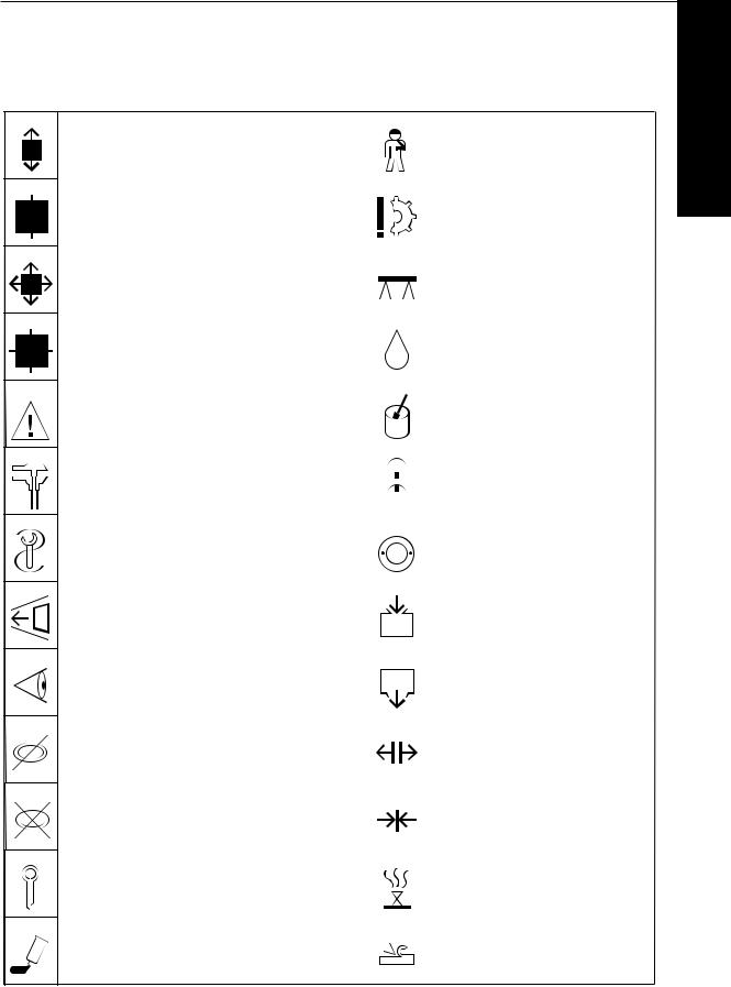
Bildzeichenerklärung
Werkstatthandbuch BFM 1015/ C
Bildzeichenerklärung
|
Zerlegen |
Personenschäden verhüten |
|||
|
von Baugruppen |
Hinweis auf Gefahrenstelle |
1 |
||
|
Zusammenbauen |
Materialschaden verhüten |
|||
|
zu einer Baugruppe |
Teilbeschädigung |
|||
|
Abbauen — Ausbauen |
Unterbauen — Abstützen — |
|||
|
behindernder Teile |
Abfangen |
|||
|
Einbauen — Anbauen |
Einölen |
|||
|
Teile, die beim Ab-/ Ausbau hinderten |
||||
|
Achtung, wichtiger Hinweis |
Einfetten |
|||
|
Prüfen — Einstellen |
Markieren |
|||
|
z. B. Drehmomente, Maße, Drücke usw. |
vor dem Zerlegen, beachten beim |
|||
|
Zusammenbau |
||||
|
Spezialwerkzeug |
Wuchten |
|||
|
Ausgleichen von Unwuchten |
||||
|
Einbaurichtung beachten |
Einfüllen — Auffüllen — Nachfüllen |
|||
|
z. B. Öl, Kühlwasser usw. |
||||
|
Kontrollieren — Prüfen |
Ablassen |
|||
|
Sichtprüfung |
z. B. Öl, Kühlwasser usw. |
|||
|
Bedingt wiederverwendbar |
Lösen |
|||
|
Bei Bedarf auswechseln |
z. B. Lockern einer Spanneinrichtung |
|||
|
Beim Zusammenbau immer |
Spannen |
|||
|
erneuern |
z. B. Anziehen einer Spanneinrichtung |
|||
|
Entsichern — Sichern |
Entlüften |
|||
|
z. B. Splint, Sicherungsblech usw. |
||||
|
Sichern — Kleben |
Spanabhebende Bearbeitung |
|||
|
z. B. Dichtmittel flüssig |
||||
1.00.11
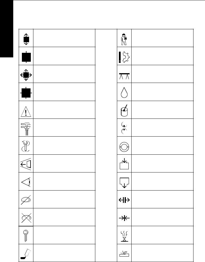
Объяснение условных обозначений
Werkstatthandbuch BFM 1015/ C
|
Объяснение условных обозначений |
|
|
Разборка |
Предупредить травмы |
|
узлов |
Указание на источник опасности |
|
1 |
Предупредить материальный ущерб |
|
Сборка |
|
|
в один узел |
Повреждение деталей |
|
Демонтаж |
Подвести опору, подпереть, |
|
закрепить |
|
|
мешающих деталей |
|
|
Монтаж деталей |
Смазать маслом |
|
которые мешали при демонтаже |
|
|
Внимание, важное указание |
Смазать консистентной смазкой |
|
Контроль-наладка |
Поставить метку |
|
напр., крутящих моментов, размеров, |
до разборки, обратить внимание при сборке |
|
давления и т.п. |
|
|
Специальный инструмент |
Сбалансировать |
|
выровнять дисбаланс |
|
|
Соблюдать направление монтажа |
Заправить, залить, долить |
|
напр., масло, воду и т.п. |
|
|
Контроль |
Слить |
|
визуальный |
напр., масло, воду и т.п. |
|
Условно пригоден к повторному |
Ослабить |
|
использованию |
|
|
при необходимости заменить |
напр., зажимное устройство |
|
При сборке всегда заменять |
Затянуть |
|
напр., зажимное устройство |
|
|
Расконтрить-законтрить |
Удалить воздух |
|
напр., шплинт, стопорную шайбу ит.п. |
|
|
Зафиксировать-склеить |
Обработка резанием |
|
напр., жидким герметиком |
|
|
1.00.11 |
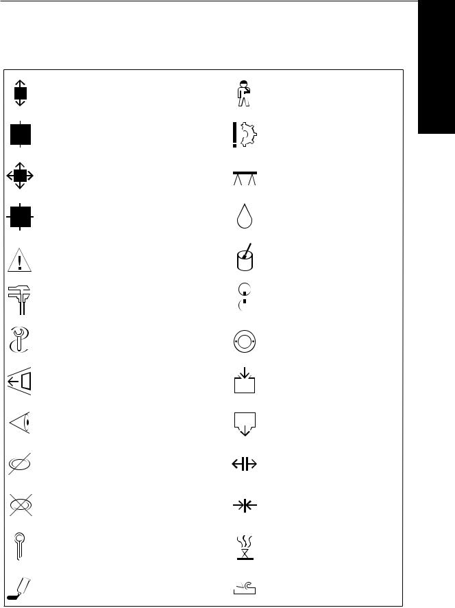
Key to Symbols
Werkstatthandbuch BFM 1015/ C
|
Key to Symbols |
||||||
|
Disassembly |
Guard against personal injury |
|||||
|
of assembly groups |
Indication of hazard |
1 |
||||
|
Reassembly |
Guard against material damage |
|||||
|
to form assembly group |
Damage to parts |
|||||
|
Remove |
Prop up — Support — Hold |
|||||
|
obstructing parts |
||||||
|
Reinstall — Remount |
Oil |
|||||
|
parts which had obstructed disassembly |
||||||
|
Attention! Impartant notice! |
Grease |
|||||
|
Check — Adjust |
Mark |
|||||
|
e. g. torque dimensions, pressures, etc. |
before disassembly, observe marks when |
|||||
|
reassembling |
||||||
|
Special tool |
Balance |
|||||
|
Eliminate any imbalance |
||||||
|
Note direction of installation |
Filling — Topping up — Refilling |
|||||
|
e. g. oil, cooling water, etc. |
||||||
|
Visual inspection |
Drain off |
|||||
|
e. g. oil, cooling water, etc. |
||||||
|
Possibly still serviceable |
Loosen — Release |
|||||
|
Renew if necessary |
e. g. loosening a clamping device |
|||||
|
Renew at each reassembly |
Tighten — Clamp |
|||||
|
e. g. tightening a clamping device |
||||||
|
Unlock — Lock |
Vent |
|||||
|
e. g. split pin, locking plate, etc. |
||||||
|
Lock — Adhere |
Machining process |
|||||
|
e. g. with liquid sealant |
||||||
1.00.11

Technische Daten
Технические данные
Specification data
Werkstatthandbuch BFM 1015/ C
1

Prüfen und Einstellen
Контроль и регудировка
Checking and adjusting BFM 1015
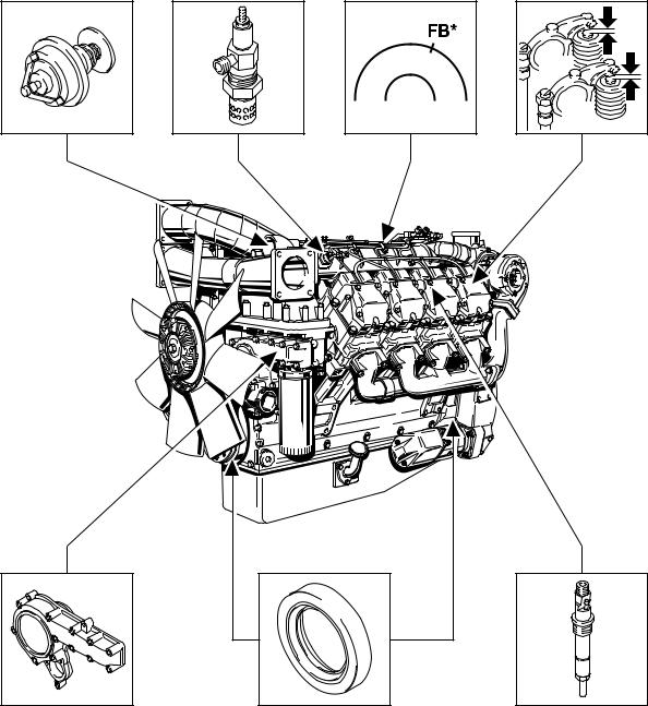
SERVICE — ARBEITEN AM KOMPLETTEN MOTOR
Сервисные работы на комплектном двигателе
SERVICE WORK ON COMPLETE ENGINE
*FB = Förderbeginn
*FB = начало подачи
*FB = commencement of delivery
![]()
|
Inhalts-Verzeichnis |
Prüfen und Einstellen |
|
Содержание |
Контроль и регулировка |
|
Table of Contents |
Checking and adjusting |
Werkstatthandbuch BFM 1015/ C
Deutsch
|
2. Prüfen und Einstellen |
Seite |
|
Ventilspiel _______________________________________________________ |
2.00.01 — 2.00.03 |
|
Einspritzventil ____________________________________________________ |
2.00.05 — 2.00.10 |
|
Förderbeginn _____________________________________________________ |
2.00.11 — 2.00.16 |
|
Austausch der Wellendichtringe ______________________________________ |
2.00.17 — 2.00.21 |
|
Thermostate austauschen ___________________________________________ |
2.00.23 — 2.00.24.2 |
|
Kühlmittelpumpe austauschen ________________________________________ |
2.00.25 — 2.00.26 |
|
Flammkerze austauschen ____________________________________________ |
2.00.27 |
2
Русский
|
2. Контроль и регулировка |
Стр. |
|
Зазор в клапанах __________________________________________________________ |
2.00.01 — 2.00.03 |
|
Форсунка _________________________________________________________________ |
2.00.05 — 2.00.10 |
|
Начало подачи ____________________________________________________________ |
2.00.11 — 2.00.16 |
|
Замена сальников вала ____________________________________________________ |
2.00.17 — 2.00.21 |
|
Замена термостатов ______________________________________________________ |
2.00.23 — 2.00.24.2 |
|
Замена насоса охлаждающей жидкости ____________________________________ |
2.00.25 — 2.00.26 |
|
Замена факельной свечи __________________________________________________ |
2.00.27 |
English
|
2. Checking and adjusting |
Page |
|
Valve clearance ___________________________________________________ |
2.00.01 — 2.00.03 |
|
Injector _________________________________________________________ |
2.00.05 — 2.00.10 |
|
Commencement of delivery __________________________________________ |
2.00.11 — 2.00.16 |
|
Replacing shaft seals _______________________________________________ |
2.00.17 — 2.00.21 |
|
Replacing thermostats ______________________________________________ |
2.00.23 — 2.00.24.2 |
|
Replacing coolant pump ____________________________________________ |
2.00.25 — 2.00.26 |
|
Replacing flame-type heater plug _____________________________________ |
2.00.27 |

|
Prüfen und Einstellen |
Ventilspiel |
||
|
Контроль и регулировка |
Зазор в клапанах |
||
|
Checking and adjusting |
Valve clearance |
||
|
Русский |
English |
||
|
Отрегулировать зазор в клапанах. |
Adjusting valve clearance. |
||
|
Специальный инструмент: |
Special tool required: |
||
|
Приспособление для проворачивания ________ 100 300 |
Cranking device __________________________ 100 300 |
||
|
Возможна настройка стандартного зазора в клапанах: |
The standard valve clearance can be adjusted: |
||
|
На холодном или теплом двигателе через минимум |
with engine cold or warm after cooling down for at |
||
|
0,5 часа после останова. |
least 0.5 h. |
||
|
Температура масла < 80°С |
Oil temperature < 80°C |
2
|
Крышка головки цилиндра снята. Приспособление |
Cylinder head cover has been removed. Cranking device |
|
для проворачивания установлено. |
has been mounted. |
|
1. Провернуть двигатель до перекрытия клапанов, цил. |
1. Turn engine until valves of |
|
1 А1. |
cyl. No. A1 overlap. |
|
Схему регулировки зазора в клапанах см. |
See specification data for valve clearance adjustment |
|
Технические данные. |
schematic. |
Указание: Перекрытие клапанов означает, что выпускные клапаны еще не закрылись, а впускные клапаны начали открываться.
Note: Valve ovelap means: Exhaust valves about to close, inlet valves about to open.
2.00.01

|
Ventilspiel |
Prüfen und Einstellen |
|
Зазор в клапанах |
Контроль и регулировка |
|
Valve clearance |
Checking and adjusting |
Deutsch
Ventilspiel einstellen.
Spezialwerkzeug:
Durchdrehvorrichtung _____________ 100 300
Die Standard-Ventilspieleinstellung ist möglich:
Am kaltenoder am warmen Motor nach einer Abkühlzeit von mindestens 0,5 h. Öltemperatur < 80° C
Zylinderkopfhaube ist abgebaut. Durchdrehvorrichtung ist angebaut.
1.Motor durchdrehen bis zum Erreichen der Ventilüberschneidung, Zyl. Nr. A1.
Ventilspieleinstellschema siehe Techn. Daten.
Hinweis: Ventilüberschneidung bedeutet: Auslaßventile sind noch nicht geschlossen, Einlaßventile beginnen zu öffnen.
Werkstatthandbuch BFM 1015/ C
2
9
9
5
2.00.01

|
Prüfen und Einstellen |
Ventilspiel |
|
Контроль и регулировка |
Зазор в клапанах |
|
Checking and adjusting |
Valve clearance |
Werkstatthandbuch BFM 1015/ C
9
|
6 |
|||
|
2 |
5 |
||
4
6
4
0
6
Deutsch
IN = Einlaßventil
EX = Auslaßventil
2.Ventilspieleinstellung am entsprechenden Zylinder mit abgewinkeltem Fühlerlehrenblatt einstellen.
Hinweis: Ventilspiel Einlaß: ______ 0,25 mm Ventilspiel Außlaß: ______ 0,30 mm
3.Kontermutter festdrehen.
Anziehvorschrift: ______________ 20 Nm
Einstellung nochmals mit Fühlerlehrenblatt überprüfen.
4.Bei Bedarf neue Dichtung auflegen. Zylinderkopfdeckel aufsetzen. Schrauben festdrehen.
Anziehvorschrift: ______________ 22 Nm
2.00.02

|
Ventilspiel |
Prüfen und Einstellen |
||
|
Зазор в клапанах |
Контроль и регулировка |
||
|
Valve clearance |
Checking and adjusting |
||
|
Русский |
English |
||
|
IN = впускной клапан |
IN = inlet valve |
||
|
EX = выпускной клапан |
EX = exhaust valve |
|
2. Отрегулировать зазор в клапанах на |
2. Adjust valve clearance on respective cylinder with |
||
|
соответствующем цилиндре с помощью плоского |
angled feeler gauge. |
||
|
щупа. |
|||
|
Указание: Зазор впускного клапана __________0,25 |
мм |
Note: Inlet valve clearance: ________________ 0.25 mm |
2 |
|
Зазор выпускного клапана ________ 0,30 |
мм |
Exhaust valve clearance: _____________ 0.30 mm |
|
|
3. Затянуть контргайку. |
3. Tighten locknut. |
|
Момент затяжки: ___________________________ 20 Нм |
Tightening specification: _________________ 20 Nm |
|
Eще раз проверить зазор с помощью плоского щупа. |
Recheck the adjustment with feeler gauge. |
|
4. В случае необходимости поставить новую |
4. Place on new gasket in place if needed. Fit inspection |
|
прокладку. Поставить на место крышку головки |
cover. Tighten bolts. |
|
цилиндра. Затянуть болты. |
|
|
Момент затяжки: ___________________________ 22 Нм |
Tightening specification: _________________ 22 Nm |
2.00.02

|
Prüfen und Einstellen |
Ventilspiel |
||
|
Контроль и регулировка |
Зазор в клапанах |
||
|
Checking and adjusting |
Valve clearance |
||
|
Русский |
English |
||
|
5. Снять приспособление для проворачивания. |
5. Remove cranking device. Fit cover with new gasket to |
||
|
Установить крышку с новой прокладкой на картере |
adapter housing. Tighten bolts. |
||
|
маховика. Затянуть болты. |
|||
|
Момент затяжки: ___________________________ 21 Нм |
Tightening specification: _________________ 21 Nm |
2
2.00.03

|
Ventilspiel |
Prüfen und Einstellen |
|
Зазор в клапанах |
Контроль и регулировка |
|
Valve clearance |
Checking and adjusting |
Deutsch
5.Durchdrehvorrichtung abbauen. Verschlußdeckel mit neuer Dichtung am Anschlußgehäuse anbauen. Schrauben festdrehen.
Anziehvorschrift: ______________ 21 Nm
Werkstatthandbuch BFM 1015/ C
3
ß
4
6
2
2.00.03

Prüfen und Einstellen
Контроль и регулировка
Checking and adjusting
|
Werkstatthandbuch BFM 1015/ C |
Deutsch |
2

Service-Telefon für technische Rückfragen
Сервисный телефон для выяснения технических вопросов
Service telephone for technical enquiries
(0221) 822 5454
Von 08.00 bis 17.00 Uhr mit direkter Vermittlung. Nachts, an Wochenenden und an Feiertagen als Anrufbeantworter
(Wir reagieren am nächsten Arbeitstag).
C 8.00 до 17.00 прямая связь.
Ночью, по выходным и праздничным дням через автоответчик (мы ответим в следующий рабочий день)
Personal answering service from 8.00 a.m. to 5.00 p.m.
At all other times and on weekends and holidays an ansafone system operates (we call back the next working day).

|
Prüfen und Einstellen |
Einspritzventil |
|||
|
Контроль и регулировка |
Форсунка |
|||
|
Checking and adjusting |
Injector |
|||
|
Русский |
English |
|||
|
Демонтаж-монтаж и контроль форсунок |
Removing/refitting and inspecting injectors |
|||
|
Обычный инструмент: |
Commercial tools required: |
|||
|
Прибор для контроля форсунок __________________ 3208 |
Nozzle tester _______________________________ 3208 |
|||
|
Ключ с захватом разм.17 ______________________ 4550-1 |
Claw-grip wrench a/flats 17 __________________ 4550-1 |
|||
|
Длинная сменная торцовая головка разм.19 ____ 900 Lg. |
Long socket a/flats 19 _______________________ 900 lg |
|||
|
Специальный инструмент: |
Special tools required: |
|||
|
Съемник _____________________________________ 110 030 |
Extractor _______________________________ 110 030 |
|||
|
Специальные клещи для топливопровода |
Special pliers for |
|||
|
слива просачивающегося топлива ____________ 110 120 |
fuel-leakage line __________________________ 110 120 |
|||
|
Ключ для шлицевой гайки ____________________ 110 130 |
Slotted nut wrench _______________________ 110 130 |
|||
|
Приспособление для снятия __________________ 150 800 |
Extracting device _________________________ 150 800 |
|||
|
2 |
Указание: При работе с системой впрыскивания |
Note: Utmost cleanliness must be ensured when working |
||
|
обращать особое внимание на чистоту. |
on the injection equipment. For testing the injector |
|||
|
Для контроля форсунок использовать |
use only pure test oil to ISO 4113 or clean diesel |
|||
|
только чистое масло для контроля по |
fuel. |
|||
|
ИСО 4113 или чистое дизельное топливо. |
Крышка головки цилиндра, топливопровод высокого давления и топливопровод слива просачивающегося топлива демонтированы.
Inspection cover, injection line and fuel-leakage line have been removed.
|
1. Снять винт крепления форсунки. |
1. Remove cap screw for injector. |
|
2. При застревании форсунки воспользуйтесь ударным |
2. If injector is jammed, use tapping tool. |
|
инструментом. |
|
|
Указание: Уплотнительное кольцо также должно быть |
Note: Be sure to remove the sealing ring as well. |
|
снято. |
2.00.05
![]()
|
Einspritzventil |
Prüfen und Einstellen |
|
Форсунка |
Контроль и регулировка |
|
Injector |
Checking and adjusting |
Deutsch
Einspritzventile ausund einbauen und prüfen.
Handelsübliche Werkzeuge:
Düsenprüfgerät ____________________ 3208 Klauenschlüssel SW 17 ___________ 4550 — 1 Lange Stecknuß SW 19 ____________ 900 Lg
Spezialwerkzeuge:
Auszieher _____________________ 110 030 Spezialzange für Leckkraftstoff-
leitung _____________________ 110 120 Nutmutterschlüssel ______________ 110 130 Ausziehvorrichtung ______________ 150 800
Hinweis: Bei Arbeiten an der Einspritzausrüstung auf größte Sauberkeit achten. Zur Prüfung der Einspritzventile reines Prüföl nach ISO 4113 oder sauberen Dieselkraftstoff verwenden.
Zylinderkopfdeckel, Einspritzleitung und Leckkraftstoffleitung ist abgebaut
1.Überwurfschraube für Einspritzventil ausbauen.
2.Bei Festsitz des Einspritzventils Schlagwerkzeug benutzen.
Hinweis: Darauf achten, daß der Dichtring mit ausgebaut wird.
Werkstatthandbuch BFM 1015/ C
5
2
3
7
3
7
5
2.00.05

|
Prüfen und Einstellen |
Einspritzventil |
|
Контроль и регулировка |
Форсунка |
|
Checking and adjusting |
Injector |
Werkstatthandbuch BFM 1015/ C
e
4
6
2
1
5
8 r
Deutsch
Achtung
Hände weg vom Düsenstrahl. Der Kraftstoff dringt tief in das Fleisch ein und kann zu Blutvergiftung führen.
3.Einspritzventil an das Düsenprüfgerät anbauen.
4.Prüfung des Öffnungsdruckes
Hebel des Düsenprüfgerätes bei zugeschaltetem Manometer langsam niederdrücken. Der Druck bei dem der Zeiger stehenbleibt oder plötzlich abfällt, ist der Öffungsdruck.
Öffnungsdruck: ___________ 290 + 8 bar.
5.Einstellen des Öffnungsdruckes am Einspritzventil
Überwurfmutter abschrauben, alle Teile ausbauen.
Hinweis: Schutzbacken verwenden
Folge der Einzeldemontage:
1.Überwurfmutter
2.Einspritzdüse
3.Zwischenstück
4.Druckbolzen
5.Druckfeder
6.Ausgleichscheiben
2.00.06

|
Einspritzventil |
Prüfen und Einstellen |
|
Форсунка |
Контроль и регулировка |
|
Injector |
Checking and adjusting |
Русский
Внимание!
Будьте осторожны при появлении топливной струи из форсунки. Топливо проникает глубоко в тело и может привести к заражению крови.
3.Подсоединить форсунку к прибору для контроля форсунок.
4.Контроль давления начала впрыска
Медленно опустить рычаг прибора для контроля форсунки при подсоединенном манометре. Давление, при котором стрелка останавливается или вдруг отходит назад, есть давление начала впрыска.
Давление начала впрыска: ____________ 290 + 8 бар
5.Регулировка давления начала впрыска на форсунке
Отвернуть накидную гайку, снять все детали.
Указание: Воспользоваться мягкими вставками к тискам
Последовательность операций демонтажа:
1.Накидная гайка
2.Форсунка
3.Проставка
4.Нажимной болт
5.Пружина форсунки
6.Компенсационные прокладки
English
Caution
Beware of injection nozzle fuel jet. The fuel penetrates deeply into the skin tissue and may cause blood poisening.
3. Connect injector to nozzler tester.
4. Checking opening pressure
With pressure gauge switched on, slowly press down lever of nozzle tester. The pressure at which the gauge
pointer stops or suddenly drops, is the opening 2 pressure.
Opening pressure: __________________ 290 + 8 bar.
5. Adjusting the opening pressure on the injector
Unscrew cap nut and remove all parts.
Note: Use protective jaws.
Sequence of parts disassembly:
1.Cap nut
2.Injection nozzle
3.Adapter
4.Thrust pin
5.Compression spring
6.Shims
2.00.06

|
Prüfen und Einstellen |
Einspritzventil |
||
|
Контроль и регулировка |
Форсунка |
||
|
Checking and adjusting |
Injector |
||
|
Русский |
English |
||
|
6. Отрегулировать давление путем подбора |
6. Adjust pressure by selecting appropriate shim. |
||
|
прокладок. Более толстая прокладка дает более |
A thicker shim increases the opening pressure. |
||
|
высокое давление начала впрыска. Собрать |
Tighten cap nut with a torque of 40 — 50 Nm. |
||
|
форсунку. Затянуть накидную гайку с моментом |
Recheck injector on nozzle tester. |
||
|
затяжки 40 — 50 Нм. Снова проверить форсунку на |
|||
|
приборе для контроля. |
|
7. |
Контроль герметичности |
7. Checking for tightness |
|
|
Подсушить форсунку и ее корпус с помощью струи |
Dry nozzle and nozzle holder — blow out with com- |
||
|
2 |
воздуха. Медленно опустить вниз рычаг контрольного |
pressed air. Press down handlever of tester until a |
|
|
прибора до метки давления на 20 бар ниже, чем |
pressure of up to about 20 bar below the previous |
||
|
ранее показанное прибором давление начала |
opening pressure reading is attained. |
||
|
впрыска. |
|||
|
8. Форсунка герметична, если в течение 10 секунд не |
8. Nozzle is tight if there is no dripping within a period of |
|
появится ни одной капли. |
10 seconds. |
|
9. Если появится хотя бы одна капля, необходимо |
9. In case of a drip, the injector must be dismantled and |
|
разобрать форсунку и устранить неплотность |
cleaned to remedy the leak. If this does not cure the |
|
путем очистки. Если это не поможет, необходимо |
leak, the injector must be replaced. |
|
заменить форсунку. |
|
|
Ремонт форсунки не допускается. |
Reworking is not permissible. |
2.00.07

|
Einspritzventil |
Prüfen und Einstellen |
|
Форсунка |
Контроль и регулировка |
|
Injector |
Checking and adjusting |
Deutsch
6.Durch Auswahl der erforderlichen Scheibe Druck einstellen. Stärkere Scheibe ergibt höheren Öffnungsdruck. Einspritzventil zusammenbauen. Überwurfmutter mit einem Drehmoment von 40 — 50 Nm festdrehen. Einspritzventil auf dem Düsenprüfgerät erneut prüfen.
7.Prüfung auf Dichtheit
Düse und Düsenhalter abtrocknen — mit Luft trockenblasen. Handhebel des Prüfgerätes langsam niederdrücken, bis ca. 20 bar unterhalb des vorher abgelesenen Öffnungsdruckes erreicht werden.
Werkstatthandbuch BFM 1015/ C
2
6
6
2
|
8. Düse ist dicht, wenn innerhalb 10 Sekunden |
9 |
|
kein Tropfen abfällt. |
|
9. Fällt ein Tropfen ab, ist das Einspritzventil zu |
9 |
|
|
zerlegen und die Undichtigkeit durch Reini- |
||
|
gen zu beseitigen. Ist das nicht erfolgreich, |
||
|
muß die Einspritzdüse erneuert werden. |
||
|
Nacharbeit ist nicht zulässig. |
||
2.00.07

|
Prüfen und Einstellen |
Einspritzventil |
||||||
|
Контроль и регулировка |
Форсунка |
||||||
|
Checking and adjusting |
Injector |
||||||
|
Werkstatthandbuch BFM 1015/ C |
Deutsch |
||||||
|
10. Schnarrund Strahlprüfung |
|||||||
|
9 |
|||||||
|
Manometer des Prüfgerätes abschalten. |
|||||||
|
Die Schnarrprüfung ermöglicht eine hörbare |
|||||||
|
Prüfung der Leichtgängigkeit der Düsennadel |
|||||||
|
im Düsenkörper. Neue Einspritzventile haben |
|||||||
|
gegenüber gebrauchten ein geändertes |
|||||||
|
Schnarrverhalten. |
|||||||
|
Durch Verschleiß im Nadelsitzbereich ver- |
|||||||
|
schlechtert es sich. Schnarrt eine Einspritz- |
|||||||
|
düse trotz Reinigung nicht, muß sie durch |
|||||||
|
eine neue ersetzt werden. |
|||||||
|
Ein gebrauchtes Einspritzventil muß bei |
|||||||
|
schneller Hebeltätigkeit hörbar schnarren und |
|||||||
|
dabei gut zerstäubt abspritzen. Das Strahl- |
|||||||
|
2 |
bild kann dabei gegenüber dem eines neuen |
||||||
|
Einspritzventils deutlich unterschiedlich sein. |
|||||||
11.Neuen Dichtring auflegen. Überwurfschraube und Dichtring mit Montagemittel Deutz S1 bestreichen.
12. Einspritzventil einsetzen.
4
2.00.08

|
Einspritzventil |
Prüfen und Einstellen |
|
Форсунка |
Контроль и регулировка |
|
Injector |
Checking and adjusting |
Русский
10.Контроль дребезжания и струи
Отсоединить манометр контрольного прибора.
Контроль дребезжания позволяет проверить на слух легкость хода иглы распылителя форсунки в корпусе. У новых форсунок характер дребезжания иной, чем у бывших в употреблении. Это обусловлено износом в области седла иглы. Если форсунка не издает дребезжащего звука несмотря на чистку, ее необходимо заменить.
Бывшая в употреблении форсунка должна при быстрой работе рычагом издавать четкое дребезжание и при этом хорошо распылять топливо. При этом форма струи может заметно отличаться от формы струи новой форсунки.
English
10.Buzzing and spray pattern test
Switch off pressure gauge of tester.
The buzzing test permits an audible check of the ease of movement of the nozzle needle in the nozzle body. New injectors emit a different buzzing sound as compared to used injectors. It deteriorates due to wear in the needle seat area. If an injection nozzle does not buzz despite cleaning, it must be renewed.
A used injector should buzz clearly during rapid actuation of the handlever, while exhibiting a well atomized spray pattern. The spray pattern may differ noticeably from that of a new injector.
2
|
11. Поставить новое уплотнительное кольцо. Винт с |
11. Place on new sealing ring. Apply Deutz S1 sealing |
|
головкой и уплотнительное кольцо смазать |
compound to cap screw and sealing ring. |
|
монтажным средством «Дойтц S1». |
|
12. Вставить форсунку. |
12. Insert injector. |
2.00.08

|
Prüfen und Einstellen |
Einspritzventil |
|
Контроль и регулировка |
Форсунка |
|
Checking and adjusting |
Injector |
Русский
13.Затянуть винт крепления форсунки.
Момент затяжки: ______________________ 60-80 Нм.
|
14. Захватить трубопровод слива просачивающегося |
|
|
топлива специальными клещами так, чтобы выступало |
|
|
около 15 мм. Подсоединить трубопровод слива к |
|
|
2 |
форсунке. |
|
Надеть трубопровод слива на тройник. |
|
|
Указание: Резиновые шланги трубопровода слива |
|
|
просачивающегося топлива, снятые с |
|
|
шлангового патрубка или тройника, |
|
|
подлежат обязательной замене. |
15.Протянуть трубопровод слива просачивающегося топлива и топливопровод высокого давления через резиновые уплотнения.
16.Поставить на место топливопровод высокого давления без натяга и затянуть ключом с захватом.
Момент затяжки: _____________________ 25 ± 10 Нм
Указание: Трубопроводы снова надлежащим образом закрепить хомутами.
English
13.Tighten cap screw.
Tightening specification: _____________ 60 — 80 Nm
14.Retain new fuel-leakage line with special pliers so that it protrudes by about 15 mm. Attach fuel-leak- age line to injector.
Attach fuel-leakage line to tee.
Note: Always renew rubber hoses of fuel-leakage line pulled off hose connection or tee.
15.Introduce fuel-leakage line and injection line through sealing rubber.
16.Position fuel-leakage line loosely back in place and tighten with claw-grip wrench.
Tightening specification: ____________ 25 ± 10 Nm
Note: Secure lines properly again with clamps
2.00.09

|
Einspritzventil |
Prüfen und Einstellen |
|
Форсунка |
Контроль и регулировка |
|
Injector |
Checking and adjusting |
Deutsch
13.Überwurfschraube festdrehen. Anziehvorschrift: ___________ 60 — 80 Nm
14.Neue Leckkraftstoffleitung in Spezialzange so aufnehmen, daß ca. 15 mm überstehen. Leckkraftstoffleitung auf Einspritzventil aufstecken.
Leckkraftstoffleitung auf T-Stück aufstecken.
Hinweis: Von Schlauchanschluß oder T-Stück abgezogene Gummischläuche der Leckkraftstoffleitungen sind grundsätzlich zu erneuern.
15.Leckkraftstoffleitung und Einspritzleitung durch den Dichtgummi führen.
16.Einspritzleitung wieder spannungsfrei aufsetzen und mit Klauenschlüssel festdrehen.
Anziehvorschrift: __________ 25 ± 10 Nm
Hinweis: Leitungen wieder ordnungsgemäß verschellen.
Werkstatthandbuch BFM 1015/ C
4
6
7
4
5
ß
4
4
6
5
2.00.09

|
Prüfen und Einstellen |
Einspritzventil |
|
Контроль и регулировка |
Форсунка |
|
Checking and adjusting |
Injector |
Werkstatthandbuch BFM 1015/ C
4
6
ß
Deutsch
17.Zylinderkopfdeckel mit neuer Dichtung aufsetzen. Schrauben festdrehen.
Anziehvorschrift: ______________ 22 Nm
2
2.00.10
 Loading…