-
Contents
-
Table of Contents
-
Bookmarks
Quick Links
YOUR OPERATOR’S MANUALS
Vehicle document wallet in the vehicle
Here you can find information on operation, service work and the guarantee for
your vehicle in printed form.
Digital on the Internet
You can access the Operator’s Manual on the Mercedes-Benz homepage.
Digital as an app
The Mercedes-Benz Guides app is available free of charge in common app stores.
É9605843273vËÍ
9605843273
Order no. 6462 9543 02 Part no. 960 584 32 73 Edition 2019-06
®
TM
Apple
iOS
Android
Actros/Arocs
Mercedes-Benz
Summary of Contents for Mercedes-Benz Actros
This manual is also suitable for:
Arocs
There’re some MERCEDES Benz Actros Truck Service Manuals, Parts Catalog PDF above the page.
The first MERCEDES ACTROS was released in 1996. A few years before the debut of the advanced family, the German trucks manufacturer was thinking about updating the line of
heavy vehicles.
The SK series is outdated in many ways. The indestructible truck began to lose in demand, and the manufacturer needed something fundamentally new. As a result, the
Mercedes Actros family appeared.
The developers went a revolutionary way. From a simple predecessor in the design, there was practically nothing left. The model has noticeably changed, and a lot of electronics have appeared
inside. This had a positive effect on the quality of work and the level of comfort, but reliability decreased slightly.
The car received the standard appearance and design for heavy truck models — a large rectangular cabin and a robust chassis. Mercedes did not forget about the corporate identity.
The front part of the truck cabin was decorated with a powerful radiator grill, characteristic of the brand’s products, and a large company icon.
![]()
Electronic systems, Actros, model 963
Functional description
– This printout will not be recorded by the update service. Status: 09 / 2011 –

Mercedes>Benz Service
Electronic systems, Actros, model 963
Technical status 09.11
Daimler AG . Technical Information and Workshop Equipment(GSP/OI)
D$70546 Stuttgart
– This printout will not be recorded by the update service. Status: 09 / 2011 –

Information and copyright
Product portfolio
You can also find comprehensive information about our complete product portfolio on our Internet portal: Link: http://aftersales.mercedes>benz.com
Questions and suggestions
If you have any questions or suggestions concerning this product, please write to us.
|
E>Mail: |
customer.support@daimler.com |
|
Telefax: |
+49>(0)18 05/0 10>79 78 |
or alternatively
Address: Daimler AG GSP/OIS,
HPC R822, W002
D>70546 Stuttgart (Germany)
©2011 by Daimler AG
This document, including all its parts, is protected by copyright.
Any further processing or use requires the previous written consent of Daimler AG, Department GSP/OIS, HPC R822, W002, D>70546 Stuttgart.
This applies in particular to reproduction, distribution, alteration, translation, microfilming and storage and/or processing in electronic systems, including databases and online services.
|
Image no. of title image: |
W00.01>1016>00 |
|
Order no. of this publication: |
6517 1261 02 > HLI 000 000 02 89 |
|
09/11 |
– This printout will not be recorded by the update service. Status: 09 / 2011 –

Preface
SN00.00>W>0001>01HA Preface
This brochure
Actros electronic systems, model 963
is intended for the technical personnel responsible for service and maintenance of Mercedes>Benz trucks.
The content of this brochure is split up into:
• function descriptions
• component descriptions
• Description of locations of electrical connectors, sockets and ground points
All the data listed in this brochure correspond with the technical status as per September 2011.
Any changes or supplements hereto will be published in the Workshop Information System (WIS) only.
Additional documents for model 963, such as maintenance and repair instructions or wiring diagrams are also available in the Workshop Information System (WIS).
Mercedes>Benz
W‘rth plant, GSP/TTM
September 2011
|
i Electronic systems, Actros, model 963 > 09/2011 > |
1 |
– This printout will not be recorded by the update service. Status: 09 / 2011 –

Contents
|
SN00.00>W>0110H |
Overview of as>built configuration and function descriptions |
2.8.11 |
|
MODEL 963 |
|
Function descriptions |
|||
|
Overall network |
Page 15 |
||
|
Overall network, function |
Page 16 |
||
|
Maintenance system, function |
Page 22 |
||
|
Maintenance system, overall network |
Page 23 |
||
|
Data acquisition function |
Page 24 |
||
|
Data storage function |
Page 29 |
||
|
Normal mode displays function |
Page 30 |
||
|
Reset service item function |
Page 32 |
||
|
Forecast calculation, function |
Page 34 |
||
|
Life cycle consumption calculation, |
Page 35 |
||
|
function |
|||
|
Transmission automation, function |
Page 37 |
||
|
Transmission automation, overall network |
Page 40 |
||
|
Operation, function |
Page 41 |
||
|
Driver information, function |
Page 44 |
||
|
Transmission mode, function |
Page 45 |
||
|
Shifting the transmission, function |
Page 46 |
||
|
Controlling the clutch, function |
Page 52 |
||
|
Countershaft brake, function |
Page 54 |
||
|
Level control, function |
Page 56 |
||
|
Level control, overall network |
Page 59 |
||
|
Axle load measuring system, function |
Page 60 |
||
|
Monitoring/control of specified level, |
Page 62 |
||
|
function |
|||
|
Changeover from level 1 to level 2, |
Page 64 |
||
|
function |
|||
|
Raise/lower vehicle frame manually, |
Page 66 |
||
|
function |
|||
|
Store frame height, function |
Page 68 |
||
|
Constant frame height when |
Page 70 |
||
|
loading/unloading, function |
|||
|
Raise/lower lift axle, function |
Page 73 |
||
2
– This printout will not be recorded by the update service. Status: 09 / 2011 –

|
Contents |
|||
|
Starting>off aid, function |
Page 76 |
||
|
Load/relieve additional axles, function |
Page 78 |
||
|
Roll control, function |
Page 81 |
||
|
Roll control, overall network |
Page 84 |
||
|
Tire pressure monitor, function |
Page 85 |
||
|
Tire pressure monitor, overall network |
Page 86 |
||
|
Tire pressure monitor, driver information |
Page 87 |
||
|
Electronic Brake Control, function |
Page 88 |
||
|
Electronic Brake Control, overall network |
Page 92 |
||
|
Brake application on front axle with |
Page 93 |
||
|
Electronic Brake Control, function |
|||
|
Brake application on front axle without |
Page 95 |
||
|
Electronic Brake Control, function |
|||
|
Brake application on rear axle with |
Page 97 |
||
|
Electronic Brake Control, function |
|||
|
Brake application on rear axle without |
Page 99 |
||
|
Electronic Brake Control, function |
|||
|
Trailer control with Electronic Brake |
Page 101 |
||
|
Control, function |
|||
|
Trailer control without Electronic Brake |
Page 104 |
||
|
Control, function |
|||
|
Auxiliary braking effect, function |
Page 106 |
||
|
Electronic Stability Program, function |
Page 108 |
||
|
Electronic Stability Program, overall |
Page 111 |
||
|
network |
|||
|
Intervention of Electronic Stability Program |
Page 112 |
||
|
in the event of understeer or oversteer, |
|||
|
function |
|||
|
Intervention of Electronic Stability Program |
Page 114 |
||
|
upon risk of tipping, function |
|||
|
Compressed air supply system, function |
Page 116 |
||
|
Compressed air supply system, overall |
Page 122 |
||
|
network |
|||
|
Hydraulic retarder, function |
Page 123 |
||
|
Overall network of hydraulic retarder |
Page 129 |
||
|
Single>circuit power steering, function |
Page 130 |
||
|
i Electronic systems, Actros, model 963 > 09/2011 > |
3 |
– This printout will not be recorded by the update service. Status: 09 / 2011 –

Contents
|
Additional steering axle, function |
Page 133 |
||
|
Additional steering axle, overall network |
Page 137 |
||
|
Additional steering axle, hydraulics |
Page 138 |
||
|
diagram |
|||
|
Driving assistance systems, function |
Page 139 |
||
|
Driving assistance systems, overall network |
Page 144 |
||
|
Proximity Control Assist function |
Page 145 |
||
|
Active Brake Assist function |
Page 149 |
||
|
Lane Keeping Assist function |
Page 154 |
||
|
Battery sensor function |
Page 158 |
||
|
Overall network battery sensor |
Page 159 |
||
|
Modular switch panel function |
Page 160 |
||
|
Overall network modular switch panel |
Page 162 |
||
|
Instrument cluster, function |
Page 163 |
||
|
Instrument cluster, overall network |
Page 166 |
||
|
Instrument cluster operating notes |
Page 167 |
||
|
Display fuel quantity, function |
Page 168 |
||
|
Display outside temperature, function |
Page 169 |
||
|
Display engine speed, function |
Page 170 |
||
|
Display speed and travel distance, function |
Page 171 |
||
|
Display AdBlue level, function |
Page 173 |
||
|
Redundancy operation of Electronic Air> |
Page 174 |
||
|
Processing Unit (EAPU), function |
|||
|
Signaling system, function |
Page 175 |
||
|
Overall network of signaling system |
Page 177 |
||
|
Power windows, function |
Page 178 |
||
|
Power windows, overall network |
Page 181 |
||
|
Electric power sliding roof, function |
Page 182 |
||
|
Electric power sliding rood, overall |
Page 184 |
||
|
network |
|||
|
Central locking, function |
Page 185 |
||
4
– This printout will not be recorded by the update service. Status: 09 / 2011 –

|
Contents |
|||
|
Central locking, overall network |
Page 191 |
||
|
Comfort locking system function |
Page 192 |
||
|
Comfort locking system overall network |
Page 198 |
||
|
Anti>theft alarm system, function |
Page 199 |
||
|
Anti>theft alarm system, overall network |
Page 201 |
||
|
Anti>theft alarm system, status messages |
Page 202 |
||
|
Activate antitheft alarm system, function |
Page 205 |
||
|
Deactivate anti>theft alarm system, |
Page 210 |
||
|
function |
|||
|
Triggering alarm by disconnecting trailer |
Page 214 |
||
|
or semitrailer, function |
|||
|
Alarm actuation by unlocking cab, function |
Page 217 |
||
|
Triggerring alarm with panic switch, |
Page 220 |
||
|
function |
|||
|
Alarm triggering with interior protection, |
Page 223 |
||
|
function |
|||
|
Alarm triggering by steeling fuel, function |
Page 226 |
||
|
Alarm triggering by unlocking/opening a |
Page 229 |
||
|
door/flap, function |
|||
|
Alarm triggering by alarm siren, function |
Page 233 |
||
|
Drive authorization system, function |
Page 236 |
||
|
Drive authorization system overall network |
Page 238 |
||
|
Exterior lighting, function |
Page 239 |
||
|
Exterior lights, overall network |
Page 241 |
||
|
Headlamp control, function |
Page 242 |
||
|
Fog lamp actuation, function |
Page 246 |
||
|
Rear fog lamp actuation, function |
Page 247 |
||
|
Turn signal light actuation, function |
Page 248 |
||
|
Brake lights actuation, function |
Page 250 |
||
|
Backup light actuation, function |
Page 252 |
||
|
Emergency light actuation, function |
Page 253 |
||
|
Floodlight actuation, function |
Page 255 |
||
|
Interior illumination, function |
Page 257 |
||
|
Interior illumination, overall network |
Page 259 |
||
|
Ambient lighting actuation, function |
Page 260 |
||
|
Interior illumination actuation, function |
Page 261 |
||
|
i Electronic systems, Actros, model 963 > 09/2011 > |
5 |
– This printout will not be recorded by the update service. Status: 09 / 2011 –

Contents
|
Reading light actuation, function |
Page 264 |
||
|
Night light actuation, function |
Page 266 |
||
|
Exit lamp actuation, function |
Page 267 |
||
|
Windshield wiper system, function |
With code (F8X) Rain and light sensor |
Page 268 |
|
|
With code (F8X) Rain and light sensor |
Page 270 |
||
|
Windshield wiper system overall network |
Page 272 |
||
|
Multifunction steering wheel, function |
Page 273 |
||
|
Multifunction steering wheel overall |
Page 275 |
||
|
network |
|||
|
Stationary air conditioning, function |
Page 276 |
||
|
Stationary air conditioner, overall network |
Page 279 |
||
|
Load cold reservoir, function |
Page 280 |
||
|
Discharge cold reservoir function |
Page 284 |
||
|
Automatic air conditioning, function |
Page 286 |
||
|
Automatic climate control, overall network |
Page 287 |
||
|
Ventilation function |
Page 288 |
||
|
Air supply in normal operation, function |
Page 290 |
||
|
Air supply in recirculated air mode, |
Page 292 |
||
|
function |
|||
|
Temperature control function |
Page 294 |
||
|
Refrigerant circuit, function |
Page 295 |
||
|
Heater circuit function |
Page 297 |
||
|
Temperature control during heater |
Page 299 |
||
|
operation, function |
|||
|
Temperature control during AC operation, |
Page 302 |
||
|
function |
|||
|
Auxiliary heater, function |
Page 306 |
||
|
Auxiliary heater, overall network |
Page 307 |
||
|
Heater operation, function |
Page 308 |
||
|
Terminate heater operation, function |
Page 309 |
||
|
Trigger heating mode, function |
Page 315 |
||
|
Triggering the permanent heater |
Page 316 |
||
|
operation, function |
|||
|
Triggering the preselection heater |
Page 318 |
||
|
operation, function |
|||
|
Automatic triggering of heat mode, |
Page 320 |
||
|
function |
|||
6
– This printout will not be recorded by the update service. Status: 09 / 2011 –

|
Contents |
|||
|
Starting operation, function |
Page 322 |
||
|
Combustion mode, function |
Page 325 |
||
|
Control pause, function |
Page 327 |
||
|
Residual heat system, function |
Page 329 |
||
|
Residual heat system overall network |
Page 330 |
||
|
Component descriptions |
|||
|
Instrument cluster control unit (ICUC), |
A1 |
Page 331 |
|
|
component description |
|||
|
Central gateway control unit (CGW), |
A2 |
Page 333 |
|
|
component description |
|||
|
Component description drive control (CPC) |
A3 |
Page 334 |
|
|
control unit |
|||
|
Component description for engine |
A4 |
Page 335 |
|
|
management (MCM) control unit |
|||
|
Transmission control (TCM) control unit. |
A5 |
Page 337 |
|
|
component description |
|||
|
Anti>theft alarm system control unit (ATA), |
A6 |
Page 338 |
|
|
component description |
|||
|
Cab signal acquisition and actuation |
A7 |
Page 339 |
|
|
module control unit (SCA), component |
|||
|
description |
|||
|
Signal acquisition and actuation module |
A8 |
Page 340 |
|
|
control unit, frame (SCH), component |
|||
|
description |
|||
|
Electronic Brake Control control unit (EBS), |
A10b, A10c |
Page 341 |
|
|
component description |
|||
|
Retarder control unit (RCM), component |
A11 |
Page 342 |
|
|
description |
|||
|
Component description for automatic air |
A12b |
Page 344 |
|
|
conditioning control unit |
|||
|
Auxiliary heater control unit, component |
A13 |
Page 346 |
|
|
description |
|||
|
Stationary air conditioner control unit, |
A14 |
Page 347 |
|
|
component description |
|||
|
Front radar sensor (RDF) control unit, |
A15 |
Page 348 |
|
|
component description |
|||
|
Driver door control unit (DCMD), |
A16 |
Page 349 |
|
|
component description |
|||
|
Passenger door module control unit |
A17 |
Page 350 |
|
|
(DCMP), component description |
|||
|
Electronic Air>Processing Unit (EAPU), |
A18, 6.16, 6.17, 6.18 |
Page 351 |
|
|
component description |
|||
|
i Electronic systems, Actros, model 963 > 09/2011 > |
7 |
– This printout will not be recorded by the update service. Status: 09 / 2011 –
![]()
Contents
|
Front axle axle modulator, component |
A20, A20a |
Page 509 |
|
|
description |
|||
|
Rear axle axle modulator, component |
A21, A21a |
Page 511 |
|
|
description |
|||
|
Parameterizable special module (PSM) |
A22 |
Page 356 |
|
|
control unit component description |
|||
|
Electronic Stability Program (ESP) control |
A25, A25a |
Page 357 |
|
|
unit, component description |
|||
|
Level control (CLCS) control unit, |
A26 |
Page 358 |
|
|
component description |
|||
|
Driver switch group, component |
A28 |
Page 359 |
|
|
description |
|||
|
Front passenger switch group, component |
A29 |
Page 360 |
|
|
description |
|||
|
FleetBoard control unit, component |
A30 |
Page 361 |
|
|
description |
|||
|
Battery disconnect switch control unit, |
A33 |
Page 362 |
|
|
component description |
|||
|
Additional steering axle (ASA) control unit, |
A34 |
Page 364 |
|
|
component description |
|||
|
Tire pressure monitor (TPM) control unit, |
A35 |
Page 365 |
|
|
component description |
|||
|
Stationary air conditioner cold reservoir, |
A41 |
Page 366 |
|
|
component description |
|||
|
Stationary air conditioner cold reservoir |
A41 b1 |
Page 367 |
|
|
temperature sensor, component |
|||
|
description |
|||
|
Stationary air conditioner cold reservoir |
A41 |
Page 368 |
|
|
coolant pump, component description |
|||
|
Stationary air conditioner cold reservoir |
A41 y1 |
Page 369 |
|
|
solenoid valve, component description |
|||
|
Modular switch panel control unit (MSF), |
A43 |
Page 370 |
|
|
component description |
|||
|
Instrument panel switch modules, |
A44, A45, A46 |
Page 372 |
|
|
component description |
|||
|
Switch module special equipment, |
A47 |
Page 374 |
|
|
component description |
|||
|
Roof switch modules, component |
A48, A49 |
Page 375 |
|
|
description |
|||
|
Bunk switch module, component |
A50, A51 |
Page 376 |
|
|
description |
|||
|
Driver assistance system (VRDU) control |
A53 |
Page 378 |
|
|
unit, component description |
|||
|
EATU output NOx sensor, component |
A57 |
||
|
description |
i The EATU output NOx sensor control |
||
|
unit (A57) forms one unit with the EATU |
|||
|
output NOx sensor (A57 b1). |
|||
8
– This printout will not be recorded by the update service. Status: 09 / 2011 –

|
Contents |
|||
|
Vehicles with code (M5R) Engine version |
Page 379 |
||
|
EEV and vehicles with code (M5Y) Engine |
|||
|
version Euro V |
|||
|
Vehicles with code (M5Z) Engine version |
Page 381 |
||
|
Euro VI |
|||
|
Pump module, component description |
A58 |
Page 384 |
|
|
i The SCR control unit (A58) forms one |
|||
|
unit with the pump module. |
|||
|
Exhaust aftertreatment (ACM) control unit, |
A60 |
||
|
component description |
|||
|
Vehicles with code (M5R) Engine version |
Page 386 |
||
|
EEV and vehicles with code (M5Y) Engine |
|||
|
version Euro V |
|||
|
Vehicles with code (M5Z) Engine version |
Page 388 |
||
|
Euro VI |
|||
|
EATU input NOx sensor, component |
A70 |
||
|
description |
i The EATU input NOx sensor control unit |
||
|
(A70) forms one unit with the EATU input |
|||
|
NOx sensor (A70 b1). |
|||
|
Vehicles with code (M5R) Engine version |
Page 390 |
||
|
EEV and vehicles with code (M5Y) Engine |
|||
|
version Euro V |
|||
|
Vehicles with code (M5Z) Engine version |
Page 392 |
||
|
Euro VI |
|||
|
Lane Assistant camera (SPA), component |
A72 |
Page 395 |
|
|
description |
|||
|
Auxiliary heater heating unit, component |
A901 |
Page 396 |
|
|
description |
|||
|
Exhaust temperature sensor, component |
A901 B1 |
Page 398 |
|
|
description |
|||
|
Component description for coolant |
A901 B2 |
Page 399 |
|
|
temperature sensor |
|||
|
Overheating protection, component |
A901 B3 |
Page 400 |
|
|
description |
|||
|
Glow plug, component description |
A901 E |
Page 401 |
|
|
Combustion air blower, component |
A901 M1 |
Page 402 |
|
|
description |
|||
|
Auxiliary heater coolant circulation pump, |
A901 M2 |
Page 403 |
|
|
component description |
|||
|
Brake wear sensor, component description |
B1, B2 |
Page 404 |
|
|
Component description for the rpm sensor |
B13, B14 |
Page 405 |
|
|
Brake value sensor, component description |
B17, B17a |
Page 406 |
|
|
Travel and speed sensor, component |
B18 |
Page 408 |
|
|
description |
|||
|
Level control pressure sensor, component |
B20, B21 |
Page 409 |
|
|
description |
|||
|
i Electronic systems, Actros, model 963 > 09/2011 > |
9 |
– This printout will not be recorded by the update service. Status: 09 / 2011 –

Contents
|
Travel sensor, component description |
B24, B25 |
Page 410 |
|
|
Condensation sensor, component |
B26 |
Page 412 |
|
|
description |
|||
|
Parking brake pressure switch, component |
B30 |
Page 413 |
|
|
description |
|||
|
Vehicle interior temperature sensor, |
B32 |
Page 414 |
|
|
component description |
|||
|
Air conditioning pressure sensor, |
B33 |
Page 415 |
|
|
component description |
|||
|
Alarm siren, component description |
B42 |
Page 418 |
|
|
Interior protection, component description |
B43 |
Page 419 |
|
|
Component description for accelerator |
B44 |
Page 420 |
|
|
pedal sensor |
|||
|
Outside air sensor, component description |
B49 |
Page 421 |
|
|
Front axle steering angle sensor, |
B64 |
Page 422 |
|
|
component description |
|||
|
Additional steering axle steering angle |
B65 |
Page 423 |
|
|
sensor, component description |
|||
|
Steering wheel angle sensor (SAS), |
B66 |
Page 424 |
|
|
component description |
|||
|
Rain/light sensor, component description |
B81 |
Page 428 |
|
|
Outside temperature sensor, component |
B92 |
Page 430 |
|
|
description |
|||
|
Main shaft rpm sensor, component |
B501 |
Page 431 |
|
|
description |
|||
|
Countershaft rpm sensor, component |
B502 |
Page 432 |
|
|
description |
|||
|
Clutch travel sensor, component |
B503 |
Page 433 |
|
|
description |
|||
|
Range group travel sensor, component |
B504 |
Page 434 |
|
|
description |
|||
|
Transmission oil temperature sensor, |
B505 |
Page 435 |
|
|
component description |
|||
|
Component description for crankshaft |
B600 |
Page 436 |
|
|
position sensor |
|||
|
Component description for camshaft |
B601 |
Page 437 |
|
|
position sensor |
|||
|
Stationary air conditioning air outlet |
B908 |
Page 439 |
|
|
temperature sensor, component |
|||
|
description |
|||
|
Stationary air conditioning air outlet |
B909 |
Page 440 |
|
|
temperature sensor, component |
|||
|
description |
|||
|
Air quality sensor, component description |
B928 |
Page 441 |
|
|
Evaporator temperature sensor, |
B929 |
Page 442 |
|
|
component description |
|||
10
– This printout will not be recorded by the update service. Status: 09 / 2011 –

|
Contents |
|||
|
Air outlet temperature sensor, component |
B930 |
Page 443 |
|
|
description |
|||
|
Dual sun sensor, component description |
B931 |
Page 444 |
|
|
Rear lamp unit, component description |
E3, E4 |
Page 445 |
|
|
Headlamp, component description |
E5, E6 |
Page 446 |
|
|
Component description for battery sensor |
G1a |
Page 447 |
|
|
Fuel metering pump, component |
M2 |
Page 448 |
|
|
description |
|||
|
Power window motor, component |
M3 |
Page 449 |
|
|
description |
|||
|
Door central locking motor, component |
M7 |
Page 450 |
|
|
description |
|||
|
Sliding roof motor, component description |
M12 |
Page 451 |
|
|
Blower motor, component description |
M13 |
Page 452 |
|
|
Residual heat pump, component |
M20 |
Page 453 |
|
|
description |
|||
|
Fresh air/air recirculation flap actuator |
M900 |
Page 454 |
|
|
motor, component description |
|||
|
Temperature control actuator motor, |
M901 |
Page 455 |
|
|
component description |
|||
|
Defroster flap actuator motor, component |
M902 |
Page 456 |
|
|
description |
|||
|
Stationary air conditioner blower motor, |
M904 |
Page 457 |
|
|
component description |
|||
|
Air distribution flap actuator motor, |
M905 |
Page 458 |
|
|
component description |
|||
|
Tachograph (TCO) component description |
P1 |
Page 459 |
|
|
Electronic ignition lock (EIS), component |
S1 |
Page 460 |
|
|
description |
|||
|
Level control operating unit, component |
S22 |
Page 461 |
|
|
description |
|||
|
Right multifunction control lever, |
S23 |
Page 463 |
|
|
component description |
|||
|
EMERGENCY OFF switch, component |
S30 |
Page 464 |
|
|
description |
|||
|
Frame EMERGENCY OFF switch, |
S31 |
Page 465 |
|
|
component description |
|||
|
Cab unlock switch, component description |
S36, S37 |
Page 466 |
|
|
Maintenance flap button, component |
S81 |
Page 467 |
|
|
description |
|||
|
Stowage box switch, component |
S83 |
Page 468 |
|
|
description |
|||
|
Multifunction steering wheel, component |
S110, S111 |
Page 469 |
|
|
description |
|||
|
i Electronic systems, Actros, model 963 > 09/2011 > |
11 |
– This printout will not be recorded by the update service. Status: 09 / 2011 –

Contents
|
Bunk auxiliary heating button, component |
S914, S915 |
Page 470 |
|
|
description |
|||
|
Bunk auxiliary heater and stationary air |
S941, S942 |
Page 471 |
|
|
conditioning button, component |
|||
|
description |
|||
|
Bunk stationary air conditioner button, |
S951, 952 |
Page 472 |
|
|
component description |
|||
|
Transmitter key, component description |
S953 |
Page 473 |
|
|
Antenna, component description |
W3, W6, W7, W8, W9 |
Page 476 |
|
|
Diagnostic socket, component description |
X100.16 |
Page 477 |
|
|
Multifunction antenna, component |
W15 |
Page 478 |
|
|
description |
|||
|
ABS solenoid valve, component description |
Y1, Y2 |
Page 479 |
|
|
Proportional valve component description |
Y12, Y13, Y14, Y15, Y16, Y17, Y18, Y19 |
Page 480 |
|
|
Stationary air conditioner solenoid valve, |
Y27 |
Page 482 |
|
|
component description |
|||
|
Front axle level control valve unit, |
Y20 |
Page 483 |
|
|
component description |
|||
|
Level control valve unit, 2>axle vehicles, |
Y21 |
Page 485 |
|
|
component description |
|||
|
Level control valve unit, 3>axle vehicles, |
Y21a |
Page 487 |
|
|
component description |
|||
|
Refrigerant compressor magnetic clutch, |
Y40 |
Page 489 |
|
|
component description |
|||
|
Heating shutoff valve, component |
Y49 |
Page 490 |
|
|
description |
|||
|
Additional steering axle valve unit, |
Y39 |
Page 491 |
|
|
component description |
|||
|
Transmission positioner, component |
Y900 |
Page 492 |
|
|
description |
|||
|
Overflow valve with return flow, |
7.01 |
Page 494 |
|
|
component description |
|||
|
Parking brake valve, component |
14.01 |
Page 495 |
|
|
description |
|||
|
Pressure limiting valve with ventilation, |
30.03 |
Page 497 |
|
|
component description |
|||
|
Coupling head for compressed air |
35.02, 35.03 |
Page 498 |
|
|
supply/brake, component description |
|||
|
Pneumatic central clutch release bearing, |
Page 499 |
||
|
component description |
|||
|
Range group module, component |
Page 501 |
||
|
description |
|||
|
Wheel sensor, component description |
Page 502 |
||
|
Trailer control valve, component |
Page 503 |
||
|
description |
|||
12
– This printout will not be recorded by the update service. Status: 09 / 2011 –

|
Contents |
|||
|
3/2>way valve for auxiliary braking effect, |
Page 507 |
||
|
component description |
|||
|
Front axle axle modulator, component |
Page 509 |
||
|
description |
|||
|
Rear axle axle modulator, component |
Page 511 |
||
|
description |
|||
|
Retarder, component description |
Page 514 |
||
|
Steering gear, component description |
Page 520 |
||
|
Power steering fluid reservoir, component |
Page 521 |
||
|
description |
|||
|
Power steering pump, component |
Page 522 |
||
|
description |
|||
|
Additional steering axle steering cylinder, |
Page 523 |
||
|
component description |
|||
|
Additional steering axle flow dividing |
Page 524 |
||
|
valve, component description |
|||
|
Additional steering axle high pressure |
Page 525 |
||
|
filter, component description |
|||
|
Heating system heat exchanger, |
Page 526 |
||
|
component description |
|||
|
Stationary air conditioner heat exchanger, |
Page 527 |
||
|
component description |
|||
|
Stationary air conditioner check valve, |
Page 528 |
||
|
component description |
|||
|
Stationary air conditioner expansion valve, |
Page 529 |
||
|
component description |
|||
|
Condenser, component description |
Page 530 |
||
|
Evaporator, component description |
Page 531 |
||
|
Component description for expansion |
Page 532 |
||
|
valve |
|||
|
Fluid reservoir, component description |
Page 533 |
||
|
A/C compressor, component description |
Page 534 |
||
|
Auxiliary heater heat exchanger, |
Page 535 |
||
|
component description |
|||
|
Burner insert with burner tube, component |
Page 536 |
||
|
description |
|||
|
Location of components |
|||
|
Arrangement of cable and plug |
Page 537 |
||
|
connections |
|||
|
Location of line connections and |
Page 541 |
||
|
connectors, interior compartment, left |
|||
|
Location of line connections and |
Page 541 |
||
|
connectors, interior compartment, right |
|||
|
i Electronic systems, Actros, model 963 > 09/2011 > |
13 |
– This printout will not be recorded by the update service. Status: 09 / 2011 –

Contents
|
Location of line connections and |
Page 542 |
||
|
connectors, instrument panel |
|||
|
Location of line connections and |
Page 543 |
||
|
connectors, frame |
|||
|
Location of line connections and |
Page 544 |
||
|
connectors, cab |
|||
|
Location of line connections and |
Page 544 |
||
|
connectors, doors |
|||
|
Location of line connections and |
Page 545 |
||
|
connectors, roof |
|||
|
Location of line connections and |
Page 545 |
||
|
connectors, footwell, left |
|||
|
Location of line connections and |
Page 546 |
||
|
connectors, footwell, right |
|||
|
Location of line connections and |
Page 546 |
||
|
connectors, engine compartment |
|||
|
Location of line connections and |
Page 547 |
||
|
connectors, electronics compartment |
|||
|
Location of line connections and |
Page 548 |
||
|
connectors, driver seat base |
|||
|
Location of line connections and |
Page 548 |
||
|
connectors, front passenger seat base |
|||
|
Location of sockets |
Page 549 |
||
|
Location of electrical sockets |
Page 550 |
||
|
Location of ground points |
Page 551 |
||
|
Location of left engine compartment |
Page 552 |
||
|
ground points |
|||
|
Location of right engine compartment |
Page 552 |
||
|
ground points |
|||
|
Location of left interior compartment |
Page 552 |
||
|
ground points |
|||
|
Location of ground points > frame |
Page 553 |
||
|
Location of ground points > instrument |
Page 553 |
||
|
panel |
|||
14
– This printout will not be recorded by the update service. Status: 09 / 2011 –
Functions
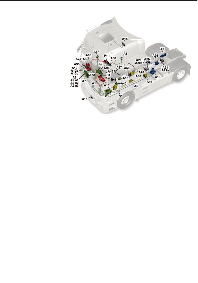
|
SN00.19>W>0001>02H |
Complete networking |
||||
|
Illustrated on model 963.4 |
|||||
|
A1 |
Instrument cluster (ICUC) control |
||||
|
unit |
|||||
|
A2 |
Central gateway control unit |
||||
|
(CGW) |
|||||
|
A2 a1 |
Central data memory (CDS) |
||||
|
A2 a2 |
Communications interface (COM) |
||||
|
control unit |
|||||
|
A2 a3 |
Maintenance system (MS) control |
||||
|
unit |
|||||
|
A3 |
Drive control (CPC) control unit |
||||
|
A4 |
Engine management control unit |
||||
|
(MCM) |
|||||
|
A5 |
Transmission control (TCM) |
||||
|
control unit |
|||||
|
A6 |
Anti>theft alarm system (ATA) |
||||
|
control unit |
|||||
|
A7 |
Cab signal acquisition and |
||||
|
actuation module control unit |
|||||
|
(SCA) |
|||||
|
W00.19>1065>76 |
|||||
|
A8 |
Frame signal acquisition and |
A17 |
Front passenger door module |
A30 |
FleetBoard“ control unit |
|
actuation module control unit |
(DCMP) control unit |
A35 |
Tire pressure monitor (TPM) |
||
|
(SCH) |
A18 |
Electronic Air Processing Unit |
control unit |
||
|
A9 |
Truck Control Center (TCC) |
(EAPU) control unit |
A40 |
Supplemental restraint system |
|
|
A10 |
Antilock brake system (ABS) |
A20 |
Front axle axle modulator |
(SRS) control unit |
|
|
control unit, 4>channel |
(Wabco) |
A43 |
Modular switch panel (MSF) |
||
|
A10b |
Electronic brake control (EBS) |
A20a |
Front axle axle modulator (Knorr) |
control unit |
|
|
control unit (Wabco) |
A21 |
Rear axle axle modulator |
A53 |
Driver assistance system (VRDU) |
|
|
A10c |
Electronic brake control (EBS) |
(Wabco) |
control unit |
||
|
control unit (Knorr) |
A21a |
Rear axle axle modulator (Knorr) |
A57 |
EATU output NOx sensor control |
|
|
A11 |
Retarder control (RCM) control |
A22 |
Parameterizable special module |
unit |
|
|
unit |
(PSM) control unit |
A58 |
SCR control unit |
||
|
A12b |
Heating, ventilation and air |
A25 |
Electronic Stability Program |
A60 |
Exhaust aftertreatment (ACM) |
|
conditioning control unit (HVAC) |
(ESP“) control unit (Wabco) |
control unit |
|||
|
A13 |
Truck auxiliary heater (ITH) |
A25a |
Electronic Stability Program |
A70 |
EATU input NOx sensor control |
|
control unit |
(ESP“) control unit (Knorr) |
unit |
|||
|
A14 |
Stationary air conditioning (IAC) |
A26 |
Level control (CLCS) control unit |
A72 |
Lane Assistant camera |
|
control unit |
B66 |
Steering wheel angle sensor |
|||
|
A15 |
Front radar sensor (RDF) control |
(SAS) |
|||
|
unit |
P1 |
Tachograph (TCO) |
|||
|
A16 |
Driver door module (DCMD) |
S1 |
Electronic ignition lock (EIS) |
||
|
control unit |
|
i Electronic systems, Actros, model 963 > 09/2011 > |
15 |
– This printout will not be recorded by the update service. Status: 09 / 2011 –

Functions
|
GF00.19>W>0004H |
Overall network, function |
2.8.11 |
MODEL 963
|
W00.19>1079>79 |
|||||
|
A1 |
Instrument cluster (ICUC) control |
A11 |
Retarder control (RCM) control unit |
A33 |
Battery disconnect switch control |
|
unit |
A12b |
Heating, ventilation and air |
unit (BESO) |
||
|
A2 |
Central gateway control unit (CGW) |
conditioning control unit (HVAC) |
A34 |
Additional steering axle (ASA) |
|
|
A2 a1 |
Central data memory (CDS) |
A13 |
Truck auxiliary heater (ITH) control |
control unit |
|
|
A2 a2 |
Communications interface (COM) |
unit |
A35 |
Tire pressure monitor (TPM) control |
|
|
control unit |
A14 |
Stationary air conditioning (IAC) |
unit |
||
|
A2 a3 |
Maintenance system (MS) control |
control unit |
A40 |
Supplemental restraint system (SRS) |
|
|
unit |
A15 |
Front radar sensor (RDF) control |
control unit |
||
|
A3 |
Drive control (CPC) control unit |
unit |
A43 |
Modular switch panel (MSF) control |
|
|
A4 |
Engine management control unit |
A16 |
Driver door module (DCMD) control |
unit |
|
|
(MCM) |
unit |
A53 |
Driver assistance system (VRDU) |
||
|
A5 |
Transmission control (TCM) control |
A17 |
Front passenger door module |
control unit |
|
|
unit |
(DCMP) control unit |
A54 |
Lower radiator shutters controller |
||
|
A6 |
Antitheft alarm system (ATA) |
A18 |
Electronic Air Processing Unit |
unit |
|
|
control unit |
(EAPU) control unit |
A55 |
Upper radiator shutters controller |
||
|
A7 |
Cab signal acquisition and |
A20 |
Front axle axle modulator (Wabco) |
unit |
|
|
actuation module control unit |
A20a |
Front axle axle modulator (Knorr) |
A57 |
EATU output NOx sensor control |
|
|
(SCA) |
A21 |
Rear axle axle modulator (Wabco) |
unit |
||
|
A8 |
Frame signal acquisition and |
A21a |
Rear axle axle modulator (Knorr) |
A58 |
SCR control unit |
|
actuation module control unit |
A22 |
Parameterizable special module |
A60 |
Exhaust aftertreatment (ACM) |
|
|
(SCH) |
(PSM) control unit |
control unit |
|||
|
A9 |
Truck Control Center (TCC) |
A25 |
Electronic Stability Program (ESP“) |
A70 |
EATU input NOx sensor control unit |
|
A10 |
Antilock brake system (ABS) control |
control unit (Wabco) |
A72 |
Lane Assistant camera |
|
|
unit, 4>channel |
A25a |
Electronic Stability Program (ESP“) |
|||
|
A10b |
Electronic Brake Control (EBS) |
control unit (Knorr) |
B42 |
Alarm siren |
|
|
control unit (Wabco) |
A26 |
Level control (CLCS) control unit |
B43 |
Interior protection sensor |
|
|
A10c |
Electronic Brake Control (EBS) |
A28 |
Driver switch group |
B66 |
Steering wheel angle sensor (SAS) |
|
control unit (Knorr) |
A30 |
FleetBoard“ control unit |
B81 |
Rain and light sensor (RLS) |
16
– This printout will not be recorded by the update service. Status: 09 / 2011 –

|
Functions |
|||||
|
CAN 1 |
Exterior>CAN |
LIN 3 |
Right multifunction control lever> |
X100.16 |
Diagnostic socket |
|
CAN 2 |
Interior CAN |
LIN |
X102.15 |
Trailer socket , 15>pin |
|
|
CAN 3 |
Frame CAN |
LIN 4 |
Left multifunction control lever LIN |
X103.7 |
ABS trailer socket 7>pin |
|
CAN 4 |
Drive train CAN |
LIN 5 |
Radiator shutters LIN |
X167.12 |
Fleet management system |
|
CAN 5 |
Climate control CAN |
LIN 6 |
LIN SCA/SCH redundancy |
electrical connector |
|
|
CAN 6a |
Front axle brakes CAN |
LIN 7 |
Button group LIN |
X910 |
Electrical connector for body |
|
CAN 6b |
Rear axle brakes CAN |
LIN 8 |
Level control LIN |
manufacturers |
|
|
CAN 6c |
Redundant brakes CAN |
LIN 9 |
Driver switch panel LIN |
XR>E1H |
CAN>H exterior cable weld point 1 |
|
CAN 6d |
ESP“ brakes CAN |
LIN 10 |
EAPU>LIN |
XR>E1L |
CAN>L exterior cable weld point 1 |
|
CAN 7 |
Trailer CAN (PSM) |
LIN 11 |
ATA>LIN |
XR>E1M |
CAN>ground exterior cable weld |
|
CAN 8 |
Body manufacturer CAN (PSM) |
P1 |
Tachograph (TCO) |
point 1 |
|
|
CAN 9 |
Telematics CAN |
S1 |
Electronic ignition lock (EIS) |
Z1 |
Cab instrument panel CAN bus star |
|
CAN 10 |
Diagnostic CAN |
S20 |
Left multifunction control lever |
point |
|
|
CAN 11 |
Trailer CAN (EBS) |
S22 |
Level control operating unit |
Z3 |
Frame CAN bus star point |
|
CAN 12 |
Radar CAN |
S23 |
Right multifunction control lever |
Z4 |
Drive CAN bus star point |
|
CAN 13 |
NOx>CAN |
S110 |
Left multifunction steering wheel |
||
|
G1a |
Battery sensor (IBS) |
button group |
|||
|
LIN 1 |
Rain/light sensor LIN |
S111 |
Right multifunction steering wheel |
ASIC |
ASIC data bus (Application System |
|
LIN 2 |
Battery sensor LIN |
button group |
Integrated Circuit) |
1General
The increase in electronic systems in the new Actros means that more and more signals now have to be made available across all the systems. This primarily has an impact on the networking, which has also gained in complexity. Alongside the familiar CAN and ASIC data bus systems the LIN data bus is now increasingly being used. The new Actros alone has 11 LIN data buses, which connect the various control units, switches or other electronic components to each other. The number of CAN data buses by contrast has only risen slightly.
2CAN data bus system
The CAN data bus system enables information to be exchanged quickly and reliably between control units over only a few lines. The information is sent or received successively (serial). The exchange is bidirectional, i.e. each control unit operates as both a transmitter and a receiver.
2.1 Transfer rates
In the new Actros up to 13 different CAN data buses are used. The majority of these CAN data buses have a transfer rate of >250 kBaud and this classes them as high>speed CAN data buses. The reasons for the increase in high>speed CAN data buses are:
•Increase in data rate (number of messages that are sent)
•Almost identical manufacturing costs as for low>speed CAN data buses
•Greater use of LIN data bus in non>critical safety areas
>>>>>>>>>>>>>>>>>>>>>>>>>>>>>>>>>>>>>>>>>>>>>>>>>>>>>>>>>>>>>>>>>>>>>>>>>>>>>>>>>>>>>>>>>
•Shortening of flash or parameterization times, in particular through increase in transfer rate for diagnostic CAN (CAN 10)
The following CAN data buses have a transfer rate of 500 kBaud:
•Exterior CAN (CAN 1)
•Interior CAN (CAN 2)
•Frame CAN (CAN 3)
•Climate control CAN (CAN 5)
•Front axle brake CAN (CAN 6a)
•Rear axle brake CAN (CAN 6b)
•Redundancy brake CAN (CAN 6c)
•Brake CAN ESP“ (CAN 6d)
•Diagnostic CAN (CAN 10)
•Radar CAN (CAN 12)
>>>>>>>>>>>>>>>>>>>>>>>>>>>>>>>>>>>>>>>>>>>>>>>>>>>>>>>>>>>>>>>>>>>>>>>>>>>>>>>>>>>>>>>>>
|
i Electronic systems, Actros, model 963 > 09/2011 > |
17 |
– This printout will not be recorded by the update service. Status: 09 / 2011 –
![]()
Functions
The transfer rate of the drive train CAN (CAN 4) was increased to 667 kBaud, because the high number of messages had significantly increased the bus operating rate. If the data rate was not increased, then there is the risk that some messages with low priority could no longer be sent due to the bus operating rate.
To ensure that freight forwarders, for example for fleet management, can continue to call up specific information on vehicle location, current speed, etc. the transfer rate of the telematics CAN (CAN 9) has been retained at 250 kBaud.
The transfer rates have also been retained on the trailer CAN (PSM) (CAN 7), the body manufacturer CAN (PSM) (CAN  and the trailer CAN (EBS) (CAN 11). They are 125 kBaud, whereby they are still classified as low>speed CAN data buses.
The transfer rate for the NOx>CAN (CAN 13) has not been changed either and is > as before > 250 kBaud.
>>>>>>>>>>>>>>>>>>>>>>>>>>>>>>>>>>>>>>>>>>>>>>>>>>>>>>>>>>>>>>>>>>>>>>>>>>>>>>>>>>>>>>>>>
2.3CAN neutral points and bus terminating resistors
Because of the high transfer rates on high>speed CAN data buses, there may be some reflections in the lines. Bus termination resistors are used to avoid reflections that would lead to the falsification of actual information. The characteristic impedance of the electrical line is important for the bus termination resistor. The total bus terminating resistor on a high>speed CAN data bus is 60 ].
In the neutral points for the cab instrument panel CAN bus (Z1) and frame CAN bus (Z3) the bus terminating resistors are integrated into the neutral points. The drive CAN bus neutral point (Z4) only includes those ferrite elements that are also installed in the neutral points for interference suppression of
high>frequency interference pulses.
>>>>>>>>>>>>>>>>>>>>>>>>>>>>>>>>>>>>>>>>>>>>>>>>>>>>>>>>>>>>>>>>>>>>>>>>>>>>>>>>>>>>>>>>>
3LIN data bus
The LIN data bus is an inexpensive serial subbus, which replaces the CAN data bus in the area of uncritical data transfer. The voltage supply for the LIN data bus is 12 V. This is realized internally in the control units through voltage dividers. Signals are transmitted through a single>wire line. The max. data rate is 20 kBaud. Communication refers to ID>based communication. All subscribers connected to the LIN data bus receive the message, but only one subscriber responds to it.
A LIN data bus subscriber never sends information by itself, as is the case, for example with a CAN data bus subscriber. Subscribers of the LIN data bus only ever respond to a query.
2.2Gateways
To compensate for the different transfer speeds, some control units also act as a gateway:
•The central gateway control unit (CGW) (A2) routes the respective messages from the exterior, interior, frame, telematics and diagnostic CAN (CAN 1, 2, 3, 9 and 10).
•The modular switch panel (MSF) control unit (A43) acts as a gateway between the interior CAN (CAN 2), the ASIC data bus (ASIC) and the three LIN data buses to the button groups on the multifunction steering wheel, the left multifunction control lever and the level control operating unit.
•The Electronic Brake Control (EBS) control unit (A10b) or (A10c), depending on the version, sends the messages from the frame CAN (CAN 3) to the front axle brake CAN (CAN 6a), the rear axle brake CAN (CAN 6b), the brake CAN ESP“ (CAN 6d) as well as, where applicable, the trailer CAN (EBS) (CAN 11) and vice versa.
•The drive control (CPC) control unit (A3) acts as an interface between the frame CAN (CAN 3) and the drive train CAN
(CAN 4).
>>>>>>>>>>>>>>>>>>>>>>>>>>>>>>>>>>>>>>>>>>>>>>>>>>>>>>>>>>>>>>>>>>>>>>>>>>>>>>>>>>>>>>>>>
The bus terminator on the exterior CAN (CAN 1) is realized by using bus terminating resistors within the central gateway control unit (CGW) (A2) and the Electronic Air>Processing Unit (EAPU) control unit (A18). Located in both control units is a 120 ] resistor each. The parallel connection then yields a total bus terminating resistance of 60 ].
In the diagnostic CAN (CAN 10) the bus terminator is realized by a 60 ] resistor in the central gateway control unit (CGW) (A2).
>>>>>>>>>>>>>>>>>>>>>>>>>>>>>>>>>>>>>>>>>>>>>>>>>>>>>>>>>>>>>>>>>>>>>>>>>>>>>>>>>>>>>>>>>
18
– This printout will not be recorded by the update service. Status: 09 / 2011 –

Functions
4ASIC data bus system
The previously familiar ASIC data bus system is also used in the new Actros.
The ASIC data bus (ASIC) belongs to the so>called subbuses. In contrast to conventional switches which switch via their own contacts and are connected to their components via separate electrical lines (e.g. motors, solenoid valves, switch inputs, lighting devices), the ASIC data bus performs these tasks.
The electronics installed in the ASIC signal switches notifies the modular switch panel (MSF) control unit (A43) the following via the ASIC data bus (ASIC):
fswitch position (open, closed, operated, not operated)
fFunctionality (normally closed contact, normally open contact, changeover contact)
fSystem affiliation (e.g. headlamp cleaning system button,
power take>off 1 button, etc.)
>>>>>>>>>>>>>>>>>>>>>>>>>>>>>>>>>>>>>>>>>>>>>>>>>>>>>>>>>>>>>>>>>>>>>>>>>>>>>>>>>>>>>>>>>
5Virtual control units
Each ASIC signal switch is connected over three contacts (pins) to the ASIC data bus (ASIC), and it is evaluated by the modular switch panel (MSF) control unit (A43). It is thus possible to install each ASIC signal switch at any arbitrary point on the individual switch modules.
For currents up to a maximum of 20 A there continues to be load switches which as before switch via their own contacts and are connected to their components through electrical lines.
These load switches are only connected to the switch panel via the ASIC contacts for separate background lighting.
>>>>>>>>>>>>>>>>>>>>>>>>>>>>>>>>>>>>>>>>>>>>>>>>>>>>>>>>>>>>>>>>>>>>>>>>>>>>>>>>>>>>>>>>>
6Safety strategy
Virtual control units are not equipped with their own housing. They are integrated into the hardware and software of other control units. In Star Diagnosis and the instrument cluster control unit (ICUC) (A1) they appear as independent control units. Among the virtual control units are the central data memory (CDS) (A2 a1), the communications interface (COM) control unit (A2 a2) and the maintenance system (MS) control unit (A2 a3), which are all integrated into the central gateway control unit (CGW) (A2).
With the aid of the central data memory (CDS) (A2 a1) the parameters for the electronic control units can be reset to manufacturer default settings.
Several control units have a redundant connection over LIN or CAN data buses. The redundant connection serves as an emergency communication, if the actual CAN connection malfunctions. The use of redundant LIN or CAN data buses is dependent on the safety relevance of each system.
The service brake system, for example has a redundant CAN data bus connection between the axle modulators.
LIN data buses serve as redundancies between the sensor and actuator module, cab (SCA) control unit (A7) and the sensor and actuator module, chassis (SCH) control unit (A8) as well as between the instrument cluster control unit (ICUC) (A1) and the Electronic Air>Processing Unit (EAPU) control unit (A18).
|
Instrument cluster control unit (ICUC), |
A1 |
Page 331 |
|
|
component description |
|||
|
Central gateway control unit (CGW), |
A2 |
Page 333 |
|
|
component description |
|||
|
Component description drive control (CPC) |
A3 |
Page 334 |
|
|
control unit |
|||
|
Component description for engine |
A4 |
Page 335 |
|
|
management (MCM) control unit |
|||
|
Transmission control (TCM) control unit. |
A5 |
Page 337 |
|
|
component description |
|||
|
Antitheft alarm system control unit (ATA), |
A6 |
Page 338 |
|
|
component description |
|||
|
Cab signal acquisition and actuation |
A7 |
Page 339 |
|
|
module control unit (SCA), component |
|||
|
description |
|||
|
Signal acquisition and actuation module |
A8 |
Page 340 |
|
|
control unit, frame (SCH), component |
|||
|
description |
|||
|
Electronic Brake Control (EBS) control unit, |
A10b, A10c |
Page 341 |
|
|
component description |
|||
|
Retarder control unit (RCM), component |
A11 |
Page 342 |
|
|
description |
i Only in vehicles with code (B3H) |
||
|
Secondary water retarder. |
|||
|
i Electronic systems, Actros, model 963 > 09/2011 > |
19 |
– This printout will not be recorded by the update service. Status: 09 / 2011 –

Functions
|
Component description for automatic air |
A12b |
Page 344 |
|
|
conditioning control unit |
|||
|
Auxiliary heater control unit, component |
A13 |
Page 346 |
|
|
description |
i Only in vehicles with code (D6M) Cab |
||
|
auxiliary water heater or with code (D6N) |
|||
|
Cab and engine auxiliary water heater. |
|||
|
Stationary air conditioner control unit, |
A14 |
Page 347 |
|
|
component description |
|||
|
Front radar sensor (RDF) control unit, |
A15 |
Page 348 |
|
|
component description |
|||
|
Driver door control unit (DCMD), |
A16 |
Page 349 |
|
|
component description |
|||
|
Passenger door module control unit |
A17 |
Page 350 |
|
|
(DCMP), component description |
|||
|
Electronic Air>Processing Unit (EAPU), |
A18 |
Page 351 |
|
|
component description |
i The Electronic Air>Processing Unit |
||
|
(EAPU) control unit (A18) forms a module |
|||
|
together with the Electronic Air>Processing |
|||
|
Unit (EAPU). |
|||
|
Front axle axle modulator, component |
A20, A20a |
Page 509 |
|
|
description |
|||
|
Rear axle axle modulator, component |
A21, A21a |
Page 511 |
|
|
description |
|||
|
Parameterizable special module (PSM) |
A22 |
Page 356 |
|
|
control unit component description |
|||
|
Electronic Stability Program (ESP) control |
A25, A25a |
Page 357 |
|
|
unit, component description |
|||
|
Level control (CLCS) control unit, |
A26 |
Page 358 |
|
|
component description |
|||
|
FleetBoard control unit, component |
A30 |
Page 361 |
|
|
description |
|||
|
Battery disconnect switch control unit, |
A33 |
Page 362 |
|
|
component description |
i Only in vehicles with one of the |
||
|
following codes: |
|||
|
• Code (E5T) ADR model class EX/II, |
|||
|
including AT |
|||
|
• Code (E5U) ADR model class EX/III, |
|||
|
including EX/II and AT |
|||
|
• Code (E5V) ADR model class FL, |
|||
|
including EX/II, EX/III and AT |
|||
|
• Code (E5X) ADR model class AT |
|||
|
• Code (E5Z) Accessories, ADR |
|||
|
• Code (E9D) Preinstallation, for bipolar |
|||
|
battery circuit breaker |
|||
|
• Code (E9E) ADR preinstallation, without |
|||
|
chassis shielding |
|||
|
Additional steering axle (ASA) control unit, |
A34 |
Page 364 |
|
|
component description |
|||
|
Tire pressure monitor (TPM) control unit, |
A35 |
Page 365 |
|
|
component description |
|||
20
– This printout will not be recorded by the update service. Status: 09 / 2011 –

|
Functions |
|||
|
Modular switch panel control unit (MSF), |
A43 |
Page 370 |
|
|
component description |
|||
|
Driver assistance system control unit |
A53 |
Page 378 |
|
|
(VRDU), component description |
|||
|
EATU output NOx sensor, component |
A57 |
||
|
description |
i The EATU output NOx sensor control |
||
|
unit (A57) together with the EATU output |
|||
|
NOx sensor (A57 b1) forms a unit. |
|||
|
Vehicles with code (M5R) EEV engine |
Page 379 |
||
|
version and vehicles with code (M5Y) Euro |
|||
|
V engine version |
|||
|
Vehicles with code (M5Z) Euro VI engine |
Page 381 |
||
|
version |
|||
|
Pump module, component description |
A58 |
Page 384 |
|
|
i The SCR control unit (A58) together |
|||
|
with the pump module forms a unit. |
|||
|
Exhaust aftertreatment (ACM) control unit, |
A60 |
||
|
component description |
|||
|
Vehicles with code (M5R) EEV engine |
Page 386 |
||
|
version and vehicles with code (M5Y) Euro |
|||
|
V engine version |
|||
|
Vehicles with code (M5Z) Euro VI engine |
Page 388 |
||
|
version |
|||
|
EATU input NOx sensor, component |
A70 |
||
|
description |
i The EATU input NOx sensor control unit |
||
|
(A70) together with the EATU input NOx |
|||
|
sensor (A70 b1) forms a unit. |
|||
|
Vehicles with code (M5R) EEV engine |
Page 390 |
||
|
version and vehicles with code (M5Y) Euro |
|||
|
V engine version |
|||
|
Vehicles with code (M5Z) Euro VI engine |
Page 392 |
||
|
version |
|||
|
Lane Assistant (SPA) camera, component |
A72 |
Page 395 |
|
|
description |
|||
|
Steering wheel angle sensor (SAS), |
B66 |
Page 424 |
|
|
component description |
|||
|
Tachograph (TCO) component description |
P1 |
Page 459 |
|
|
Electronic ignition lock (EIS), component |
S1 |
Page 460 |
|
|
description |
|||
|
i Electronic systems, Actros, model 963 > 09/2011 > |
21 |
– This printout will not be recorded by the update service. Status: 09 / 2011 –
Functions
|
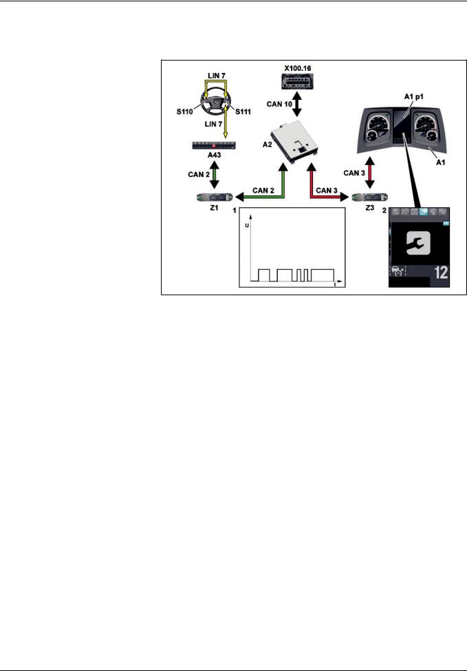
GF00.20>W>0005H |
Maintenance system, function |
2.8.11 |
MODEL 963
1CAN messages
2«Maintenance» menu
|
A1 |
Instrument cluster (ICUC) control |
|
unit |
|
|
A1 p1 |
Multifunction display |
|
A2 |
Central gateway control unit |
|
(CGW) |
|
|
A43 |
Modular switch panel (MSF) |
|
control unit |
|
|
CAN 2 |
Interior CAN |
|
CAN 3 |
Frame CAN |
|
CAN 10 |
Diagnostic CAN |
|
LIN 7 |
Button group LIN |
|
S110 |
Left multifunction steering wheel |
|
button group |
|
W00.20>1076>76 |
|||
|
S111 Right multifunction steering wheel |
Z1 Cab instrument panel CAN bus star |
Z3 |
Frame CAN bus star point |
|
button group |
point |
X100.16 |
Diagnostic socket |
General information
The maintenance system (WS):
fIs a software which is integrated as a virtual control unit into the central gateway control unit (CGW) (A2),
frecords all the required measurement data as CAN messages
(1) using the CAN data bus system and
fcalculates the load>dependent service life and forecast data for each maintenance item in order to determine the service dates.
i Load>dependent forecasting is used to carry out the following:
fIndividual determination of the service dates for each maintenance item and they can be called up in the «Maintenance» (2) menu of the instrument cluster control unit (ICUC) (A1).
fDisplay of pending maintenance items as a message in the multifunction display (A1 p1) when the ignition is switched on.
The menu is operated using the left multifunction steering wheel button group (S110) and the right multifunction steering wheel button group (S111).
Maintenance information is shown in the multifunction display (A1 p1) of the instrument cluster control unit (ICUC) (A1). The instrument cluster control unit (ICUC) (A1) acts as a display unit.
A maintenance item is reset using the left multifunction steering wheel button group (S110) and the right multifunction steering wheel button group (S111) or with the aid of Star Diagnosis through the diagnostic socket (X100.16).
|
Maintenance system overall network |
Page 23 |
||
|
Data acquisition function |
Page 24 |
||
|
Data storage function |
Page 29 |
||
|
Life cycle consumption calculation, |
Page 35 |
||
|
function |
|||
|
Forecast calculation, function |
Page 34 |
||
|
Normal mode displays function |
Page 30 |
||
|
Reset service item function |
Page 32 |
||
22
– This printout will not be recorded by the update service. Status: 09 / 2011 –

Functions
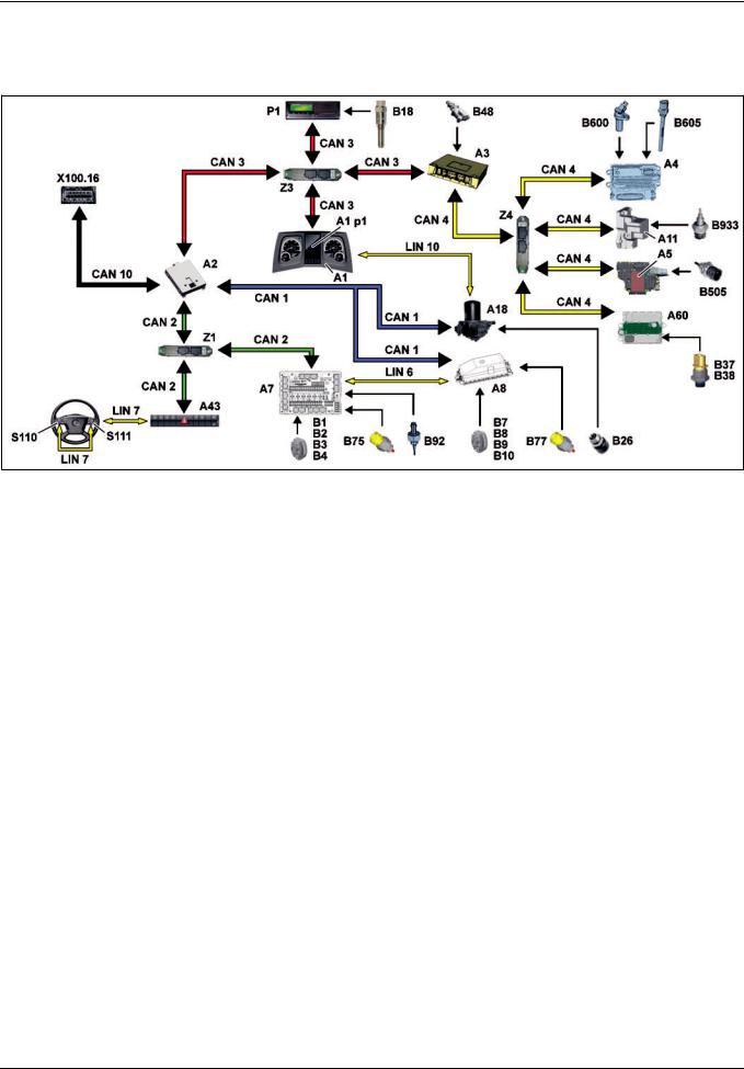
GF00.20>W>0005>02H Maintenance system overall network
|
W00.20>1079>79 |
|||||
|
A1 |
Instrument cluster (ICUC) control |
A11 |
Retarder control (RCM) control |
LIN 6 |
LIN SCA/SCH redundancy |
|
unit |
unit |
LIN 7 |
Button group LIN |
||
|
A2 |
Central gateway control unit (CGW) |
A18 |
Electronic Air Processing Unit |
LIN 10 |
EAPU>LIN |
|
A2a3 |
Maintenance system (MS) control |
(EAPU) control unit |
P1 |
Tachograph (TCO) |
|
|
unit |
A43 |
Modular switch panel (MSF) |
S110 |
Left multifunction |
|
|
A3 |
Drive control (CPC) control unit |
control unit |
steering wheel button group |
||
|
A4 |
Engine management control unit |
A60 |
Exhaust aftertreatment (ACM) |
S111 |
Right multifunction |
|
(MCM) |
control unit |
steering wheel button group |
|||
|
A5 |
Transmission control (TCM) control |
CAN 1 |
Exterior>CAN |
X100.16 |
Diagnostic socket |
|
unit |
CAN 2 |
Interior CAN |
Z1 |
Cab instrument panel CAN bus |
|
|
A7 |
Cab signal acquisition and |
CAN 3 |
Frame CAN |
star point |
|
|
actuation module control unit |
CAN 4 |
Drive train CAN |
Z3 |
Frame CAN bus star point |
|
|
(SCA) |
CAN 10 |
Diagnostic CAN |
Z4 |
Drive CAN bus star point |
|
|
A8 |
Frame signal acquisition and |
||||
|
actuation module control unit |
|||||
|
(SCH) |
|
i Electronic systems, Actros, model 963 > 09/2011 > |
23 |
– This printout will not be recorded by the update service. Status: 09 / 2011 –
Functions
|
GF00.20>W>3000H |
Data acquisition function |
2.8.11 |
MODEL 963
A1 Instrument cluster (ICUC) control unit
A1p1 Multifunction display
A2 Central gateway control unit (CGW)
A3 Drive control (CPC) control unit
A4 Engine management control unit (MCM)
A5 Transmission control (TCM) control unit
A7 Cab signal acquisition and actuation module control unit (SCA)
A8 Frame signal acquisition and actuation module control unit (SCH)
A11 Retarder control unit (RCM) (in vehicle with code (B3H) Secondary water retarder)
B48 Air filter sensor
B75 1st front axle temperature sensor
B77 1st rear axle temperature sensor
B92 Outside temperature sensor
B505 Transmission oil temperature sensor
B600 Crankshaft position sensor
B605 Engine oil fill level sensor
B933 Coolant temperature sensor (in vehicles with code (B3H) Secondary water retarder)
A18 Electronic Air Processing Unit (EAPU) control unit
A43 Modular switch panel (MSF) control unit
A60 Exhaust aftertreatment (ACM) control unit (in vehicles with code (M5Z) Euro VI engine version)
B1 Left 1st front axle brake wear sensor
B2 Right 1st front axle brake wear sensor
B3 Left 2nd front axle brake wear sensor
B4 Right 2nd front axle brake wear sensor
|
CAN 1 |
Exterior>CAN |
|
CAN 2 |
Interior CAN |
|
CAN 3 |
Frame CAN |
|
CAN 4 |
Drive train CAN |
|
CAN 10 |
Diagnostic CAN |
|
LIN 6 |
LIN SCA/SCH redundancy |
|
LIN 7 |
Button group LIN |
|
LIN 10 |
EAPU>LIN |
|
P1 |
Tachograph (TCO) |
W00.20>1078>79
B7 Left 1st rear axle brake wear sensor
B8 Right 1st rear axle brake wear sensor
B9 Left 2nd rear axle brake wear sensor
B10 Right 2nd rear axle brake wear sensor
B18 Travel and speed sensor
B26 Condensation sensor
B37 Exhaust pressure sensor upstream of diesel oxidation catalytic converter (in vehicles with code (M5Z) Euro VI engine version)
B38 Exhaust pressure sensor downstream of diesel particulate filter (in vehicles with code (M5Z) Euro VI engine version)
|
S110 |
Left multifunction steering wheel |
|
button group |
|
|
S111 |
Right multifunction steering |
|
wheel button group |
|
|
Z1 |
Cab instrument panel CAN bus |
|
star point |
|
|
Z3 |
Frame CAN bus star point |
|
Z4 |
Drive CAN bus star point |
|
X100.16 |
Diagnostic socket |
24
– This printout will not be recorded by the update service. Status: 09 / 2011 –

Functions
General information
The recording of data function enables the maintenance system (WS) to receive two different types of input factors for calculating the load>specific maintenance intervals:
fBasic data, which are determined unchangeable at first in the form of a parameterization and
fmeasured values, which are sensed continuously.
Thus, two functions are differentiated:
fAcquiring the basic data
fAcquiring the measured values
Acquiring the basic data
The maintenance system (WS) requires certain basic data (parameters), which:
fare a prerequisite for the general function and
fwhich are used to adapt the maintenance system (WS) to the vehicle and the operating fluids.
The basic data are acquired in the form of the following parameterizations:
fBasic parameterization
fVehicle>specific parameterization
fSubsequent parameterization
fParameterization of operating fluids
>>>>>>>>>>>>>>>>>>>>>>>>>>>>>>>>>>>>>>>>>>>>>>>>>>>>>>>>>>>>>>>>>>>>>>>>>>>>>>>>>>>>>>>>>
Subsequent parameterization
Subsequent parameterization:
fmakes it possible to change parameters, which are connected to constructional vehicle changes for instance or special customer’s requests, such as the «time>based servicing scheme grid» parameter and
fmay only be carried out in workshops authorized by Mercedes>Benz.
i Querying and operation are conducted using the left multifunction steering wheel button group (S110) and right multifunction steering wheel button group (S111) or using Star Diagnosis through the diagnostic socket (X100.16).
>>>>>>>>>>>>>>>>>>>>>>>>>>>>>>>>>>>>>>>>>>>>>>>>>>>>>>>>>>>>>>>>>>>>>>>>>>>>>>>>>>>>>>>>>
Basic parameterization
The basic parameterization (base parameterization):
fincludes the pre>assignment of certain parameters with values and is a prerequisite for the function of the maintenance system (WS) and
fis made at the manufacturer of the central gateway control unit (CGW) (A2).
Vehicle>specific parameterization
The vehicle>specific parameterization:
fis used to adapt the maintenance system (WS) to the vehicle model and the vehicle equipment, or to the special features of the individual maintenance items, such as
their cut>in or cutout and
fis carried out in the Mercedes>Benz production plant.
>>>>>>>>>>>>>>>>>>>>>>>>>>>>>>>>>>>>>>>>>>>>>>>>>>>>>>>>>>>>>>>>>>>>>>>>>>>>>>>>>>>>>>>>>
Parameterization of operating fluids
Parameterization of operating fluids:
fmakes it possible to change parameters with regard to the properties of fuels and lubricants, which can change during the operation of the vehicle, such as engine oil quality, engine oil viscosity, transmission oil quality, or sulfur content of the fuel and
fmay also be carried out by other workshops.
i The parameters can be checked and changed if necessary through the «Fuels and Lubricants» submenu in the «Adjustments» menu of the menu system. Querying and operation are conducted using the left multifunction steering wheel button group (S110) and right multifunction steering wheel button group (S111) or using Star Diagnosis through the
diagnostic socket (X100.16).
>>>>>>>>>>>>>>>>>>>>>>>>>>>>>>>>>>>>>>>>>>>>>>>>>>>>>>>>>>>>>>>>>>>>>>>>>>>>>>>>>>>>>>>>>
|
i Electronic systems, Actros, model 963 > 09/2011 > |
25 |
– This printout will not be recorded by the update service. Status: 09 / 2011 –

Functions
Acquiring the measured values
The measurement values are recorded using different sensors, which are connected to the system>specific control units or the locally best suited modules, e.g. on the sensor and actuator module, cab (SCA) control unit (A7).
The analog measured values are turned into corresponding CAN messages by the particular control units or modules; these CAN messages are transmitted with the aid of the CAN data bus system to the maintenance system (WS).
The maintenance system (WS):
fprocesses the recorded measured values converting them to input data for the life cycle consumption and forecast calculation, whereby the quality of processed measured values is of major significance in terms of the forecast calculation result and
fmonitors the acquired measured values for errors, exceeding limit values, and plausibility.
>>>>>>>>>>>>>>>>>>>>>>>>>>>>>>>>>>>>>>>>>>>>>>>>>>>>>>>>>>>>>>>>>>>>>>>>>>>>>>>>>>>>>>>>>
Transmission (TCM) control unit (A5)
The transmission control unit (TCM) (A5):
facquires the measured «transmission oil temperature» value from the transmission oil temperature sensor (B505) and
fsends a corresponding CAN message over the drive train CAN (CAN 4) and over the drive train CAN bus neutral point (Z4) to the drive control (CPC) control unit (A3) and from there over the frame CAN (CAN 3) and over the frame CAN bus neutral point (Z3) to the central gateway control unit (CGW) (A2).
>>>>>>>>>>>>>>>>>>>>>>>>>>>>>>>>>>>>>>>>>>>>>>>>>>>>>>>>>>>>>>>>>>>>>>>>>>>>>>>>>>>>>>>>>
Drive control (CPC) control unit (A3)
The drive control (CPC) control unit (A3):
facquires the measured value for air filter contamination by the air filter sensor (B48) and
fsends a corresponding CAN message over the frame CAN (CAN 3) and over the frame CAN bus neutral point (Z3) to the central gateway control unit (CGW) (A2).
Engine management (MCM) control unit (A4)
The engine management (MCM) control unit (A4):
facquires the measured «crankshaft rpm» value from the crankshaft position sensor (B600),
facquires the measured «engine oil temperature» value from the engine oil fill level sensor (B605),
fsends corresponding CAN messages over the drive train CAN (CAN 4) and over the drive train CAN bus neutral point (Z4) to the drive control (CPC) control unit (A3) and from there over the frame CAN (CAN 3) and over the frame CAN bus neutral point (Z3) to the central gateway control unit (CGW)
(A2).
>>>>>>>>>>>>>>>>>>>>>>>>>>>>>>>>>>>>>>>>>>>>>>>>>>>>>>>>>>>>>>>>>>>>>>>>>>>>>>>>>>>>>>>>>
Retarder control (RCM) control unit (A11)
i Only in vehicles with code (B3H) Secondary water retarder.
The retarder control unit (RCM) (A11):
facquires the measured «coolant temperature» value from the coolant temperature sensor (B933) and
fsends a corresponding CAN message over the drive train CAN (CAN 4) and over the drive train CAN bus neutral point (Z4) to the drive control (CPC) control unit (A3) and from there over the frame CAN (CAN 3) and over the frame CAN bus neutral point (Z3) to the central gateway control unit
(CGW) (A2).
>>>>>>>>>>>>>>>>>>>>>>>>>>>>>>>>>>>>>>>>>>>>>>>>>>>>>>>>>>>>>>>>>>>>>>>>>>>>>>>>>>>>>>>>>
26
– This printout will not be recorded by the update service. Status: 09 / 2011 –

Functions
Cab signal acquisition and actuation module (SCA) control unit (A7)
The sensor and actuator module, cab (SCA) control unit (A7):
facquires the measured «brake wear» value at the installed front axles from the following brake wear sensors:
fLeft 1st front axle brake wear sensor (B1)
fRight 1st front axle brake wear sensor (B2)
fLeft 2nd front axle brake wear sensor (B3)
fRight 2nd front axle brake wear sensor (B4)
facquires the measured «front axle oil temperature» value from the front axle temperature sensor
(B75) at the first front axle,
facquires the measured «outside temperature» value from the outside temperature sensor (B92) and
fsends a corresponding CAN message over the interior CAN (CAN 2) and over the cab instrument panel CAN bus neutral point (Z1) to the central gateway control unit (CGW) (A2).
>>>>>>>>>>>>>>>>>>>>>>>>>>>>>>>>>>>>>>>>>>>>>>>>>>>>>>>>>>>>>>>>>>>>>>>>>>>>>>>>>>>>>>>>>
Electronic Air>Processing Unit (EAPU) control unit (A18)
i Only in vehicles with code (B1C, B1D, B1E) Electronic Air> Processing Unit (EAPU).
The Electronic Air>Processing Unit (EAPU) control unit (A18)
frecords the measured «condensation water level» value from the condensation sensor (B26),
fdelivers the «reservoir pressure for brake circuit 1 and 2» measurement value from the integrated reservoir pressure sensors for brake circuit
1 and 2,
fsends corresponding CAN messages over the exterior CAN (CAN 1) to the central gateway control unit (CGW) (A2),
fsends corresponding LIN messages over the redundant EAPU>LIN (LIN 10) to the instrument cluster control unit (ICUC) (A1).
Sensor and actuator module, chassis (SCH) control unit (A8)
The sensor and actuator module, chassis (SCH) control unit (A8):
facquires the measured «brake wear» value at the installed rear axles from the following brake wear sensors:
>Left 1st rear axle brake wear sensor (B7)
>Right 1st rear axle brake wear sensor (B8)
>Left 2nd rear axle brake wear sensor (B9)
>Right 2nd rear axle brake wear sensor (B10)
frecords the «rear axle oil temperature» value at the first rear axle from the 1st rear axle temperature sensor (B77),
fsends corresponding CAN messages over the exterior CAN (CAN 1) to the central gateway control unit (CGW) (A2).
i In the event of any data transfer interference between the central gateway control unit (CGW) (A2) and the sensor and actuator module, cab (SCA) control unit (A7) or the sensor and actuator module, chassis (SCH) control unit (A8) the data can be sent as LIN messages redundantly over the redundancy LIN
SCA/SCH (LIN 6).
>>>>>>>>>>>>>>>>>>>>>>>>>>>>>>>>>>>>>>>>>>>>>>>>>>>>>>>>>>>>>>>>>>>>>>>>>>>>>>>>>>>>>>>>>
Exhaust aftertreatment (ACM) control unit (A60)
i Only for vehicles with code (M5Z) Engine version Euro VI.
The exhaust aftertreatment (ACM) control unit (A60)
facquires the exhaust pressure measurement values on the diesel oxidation catalytic converter/diesel particulate filter from the following pressure sensors:
>exhaust pressure sensor upstream of diesel oxidation catalytic converter (B37)
>exhaust pressure sensor downstream of diesel particulate filter (B38)
fsends a corresponding CAN message over the drive train CAN (CAN 4) and over the drive train CAN bus neutral point (Z4) to the drive control (CPC) control unit (A3) and from there over the frame CAN (CAN 3) and over the frame CAN bus neutral point (Z3) to the central gateway control unit (CGW) (A2).
|
Instrument cluster control unit (ICUC), |
A1 |
Page 331 |
|
|
component description |
|||
|
Central gateway control unit (CGW), |
A2 |
Page 333 |
|
|
component description |
|||
|
Component description drive control (CPC) |
A3 |
Page 334 |
|
|
control unit |
|||
|
Component description for engine |
A4 |
Page 335 |
|
|
management (MCM) control unit |
|||
|
Transmission control (TCM) control unit. |
A5 |
Page 337 |
|
|
component description |
|||
|
Cab signal acquisition and actuation |
A7 |
Page 339 |
|
|
module control unit (SCA), component |
|||
|
description |
|||
|
Signal acquisition and actuation module |
A8 |
Page 340 |
|
|
control unit, frame (SCH), component |
|||
|
description |
|||
|
i Electronic systems, Actros, model 963 > 09/2011 > |
27 |
– This printout will not be recorded by the update service. Status: 09 / 2011 –
![]()
Functions
|
Retarder control unit (RCM), component |
A11 |
Page 342 |
|
|
description |
i Only in vehicles with code (B3H) |
||
|
Secondary water retarder. |
|||
|
Electronic Air>Processing Unit (EAPU), |
A18 |
Page 351 |
|
|
component description |
i Only in vehicles with code (B1C) |
||
|
Electronic Air>Processing Unit (EAPU) low |
|||
|
or with code (B1D) Electronic Air> |
|||
|
Processing Unit (EAPU) mid or with code |
|||
|
(B1E) Electronic Air>Processing Unit (EAPU) |
|||
|
high. |
|||
|
Modular switch panel control unit (MSF), |
A43 |
Page 370 |
|
|
component description |
|||
|
Exhaust aftertreatment (ACM) control unit, |
A60 |
||
|
component description |
|||
|
Vehicles with code (M5R) EEV engine |
Page 386 |
||
|
version and vehicles with code (M5Y) Euro |
|||
|
V engine version |
|||
|
Vehicles with code (M5Z) Euro VI engine |
Page 388 |
||
|
version |
|||
|
Brake wear sensor, component description |
B1, B2, B3, B4, B7, B8, B9, B10 |
Page 404 |
|
|
Travel and speed sensor, component |
B18 |
Page 408 |
|
|
description |
|||
|
Condensation sensor, component |
B26 |
Page 412 |
|
|
description |
|||
|
Exhaust pressure sensor upstream of diesel |
B37 |
Page 416 |
|
|
oxidation catalytic converter, component |
i Only for vehicles with code (M5Z) |
||
|
description |
|||
|
Engine version Euro VI. |
|||
|
Exhaust pressure sensor downstream of |
B38 |
Page 417 |
|
|
diesel particulate filter, component |
i Only for vehicles with code (M5Z) |
||
|
description |
|||
|
Engine version Euro VI. |
|||
|
Outside temperature sensor, component |
B92 |
Page 430 |
|
|
description |
|||
|
Transmission oil temperature sensor, |
B505 |
Page 435 |
|
|
component description |
|||
|
Component description for crankshaft |
B600 |
Page 436 |
|
|
position sensor |
|||
|
Component description for engine oil fill |
B605 |
Page 438 |
|
|
level sensor |
|||
|
Retarder, component description |
B933 |
Page 514 |
|
|
i Only in vehicles with code (B3H) |
|||
|
Secondary water retarder. |
|||
|
The coolant temperature sensor (B933) is |
|||
|
located on the retarder. |
|||
|
Tachograph (TCO) component description |
P1 |
Page 459 |
|
|
Multifunction steering wheel, component |
S110, S111 |
Page 469 |
|
|
description |
|||
|
Diagnostic socket, component description |
X100.16 |
Page 477 |
|
28
– This printout will not be recorded by the update service. Status: 09 / 2011 –

Functions
|
GF00.20>W>3002H |
Data storage function |
2.8.11 |
MODEL 963
The maintenance system (WS) is equipped with different data memories:
fMaintenance memory
fService messages memory
fInternal memory
fMirror memory
fFault memory
Saving maintenance data in the maintenance memory
The maintenance memory:
fis a ring memory, in which the entries are stored in ascending sequence based on the date and time and
fis used to save the basic maintenance data when a maintenance item is reset.
It is possible to save data of consecutive inspections for each
maintenance item, afterwards the oldest entry is overwritten.
>>>>>>>>>>>>>>>>>>>>>>>>>>>>>>>>>>>>>>>>>>>>>>>>>>>>>>>>>>>>>>>>>>>>>>>>>>>>>>>>>>>>>>>>>
Saving service messages in the service messages memory
The service messages memory:
fis a ring memory, in which the data of up to 30 consecutive service messages can be stored,
iHere, the next service message with the highest urgency is then stored. If the data memory capacity has been reached, then the oldest entries are deleted first.
fdocuments the first>time occurrence of a service message and
fsaves the urgency level of the service message, the date, the maintenance interval travel distance, the kilometer reading of the speedometer and the relative life cycle consumption.
fsaves the major assembly designation and
fdocuments whether a service message was confirmed.
>>>>>>>>>>>>>>>>>>>>>>>>>>>>>>>>>>>>>>>>>>>>>>>>>>>>>>>>>>>>>>>>>>>>>>>>>>>>>>>>>>>>>>>>>
Saving service life data, forecast data, maintenance memory data and parameters in internal memory:
In the internal memory:
fthe service life and forecast data are always saved after switching off the ignition or after every operating hour,
fthe data are preserved after the ignition is switched off,
fthe maintenance memory data are stored after a maintenance operation was reset for a maintenance item,
fthe service memory data are saved when a message appears or is confirmed,
fparameters are saved again after a change is made and the Parameterization mode is exited and
fthe new parameters are also stored in the mirror memory of the instrument cluster control unit (ICUC) (A1) to enable parameterization to be conducted when a control unit is replaced.
Saving service life data, forecast data, maintenance memory data and parameters in mirror memory:
The mirror memory is a nonvolatile memory in the instrument cluster (ICUC) (A1), in which all the important service life data and parameters are saved every 5 operating hours.
If the central gateway control unit (CGW) (A2) has to be replaced, then the data from the mirror memory in the instrument cluster control unit (ICUC) (A1) can be copied into the new central gateway control unit (CGW) (A2). The parameterization of the central gateway control unit (CGW) (A2) is restored separately through the central data memory (CDS) in the instrument cluster (ICUC) (A1).
Storing faults and text messages in the diagnostic trouble code memory
The diagnostic trouble code memory stores any fault or text message that appears for the first time.
Consecutive new entries are stored one after the other.
|
Instrument cluster control unit (ICUC), |
A1 |
Page 331 |
|
|
component description |
|||
|
Central gateway control unit (CGW), |
A2 |
Page 333 |
|
|
component description |
|||
|
i Electronic systems, Actros, model 963 > 09/2011 > |
29 |
– This printout will not be recorded by the update service. Status: 09 / 2011 –
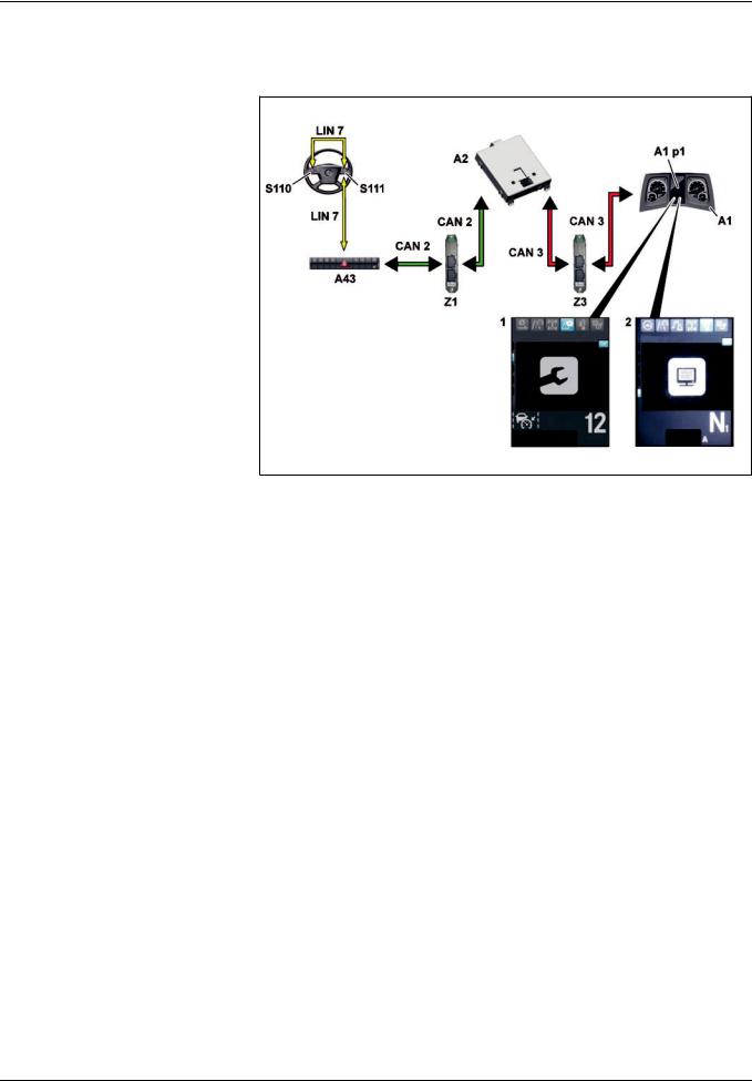
Functions
|
GF00.20>W>3003H |
Normal mode displays function |
2.8.11 |
MODEL 963
1 «Maintenance» menu
2«Diagnosis» menu
A1 Instrument cluster (ICUC) control unit
A1p1 Multifunction display
A2 Central gateway control unit (CGW)
A43 Modular switch panel (MSF) control unit
CAN 2 Interior CAN
CAN 3 Frame CAN
LIN 7 Button group LIN
S110 Left multifunction steering wheel button group
|
W00.20>1077>76 |
||
|
S111 Right multifunction steering wheel |
Z1 Cab instrument panel CAN bus star |
Z3 Frame CAN bus star point |
|
button group |
point |
General information
The central gateway control unit (CGW) (A2) sends the CAN messages with the display information over the frame CAN (CAN 3) and over the frame CAN bus neutral point (Z3) to the instrument cluster control unit (ICUC) (A1).
The maintenance information display is generated in the instrument cluster control unit (ICUC) (A1) and shown on the multifunction display (A1 p1).
The following service information is shown:
fService messages
fService information
>>>>>>>>>>>>>>>>>>>>>>>>>>>>>>>>>>>>>>>>>>>>>>>>>>>>>>>>>>>>>>>>>>>>>>>>>>>>>>>>>>>>>>>>>
Service messages
Service messages are text warnings that indicate upcoming maintenance operations. They contain the «service date» and «remaining driving distance» forecast data for the listed maintenance item or its urgency status (e.g. Service due). They are automatically generated by the maintenance system
(WS) as per their urgency status and shown on the multifunction display (A1 p1).
If there are any service messages pending, they are shown each time the ignition is switched on along with any other pending messages. Service messages can only be canceled by
acknowledging them.
>>>>>>>>>>>>>>>>>>>>>>>>>>>>>>>>>>>>>>>>>>>>>>>>>>>>>>>>>>>>>>>>>>>>>>>>>>>>>>>>>>>>>>>>>
30
– This printout will not be recorded by the update service. Status: 09 / 2011 –

Functions
Five urgency levels of service messages are differentiated:
fNo message
fEarly warning
fService due
fService now (can be acknowledged)
fService now (cannot be acknowledged)
i Any acknowledgeable service messages has to be acknowledged. The associated service dates have to be observed and the maintenance operations have to be carried out.
If service messages are skipped, the operational and road safety of the vehicle can be jeopardized. If a maintenance operation is carried out late or not at all, the wear at the vehicle or at the
major assemblies will increase at any rate.
>>>>>>>>>>>>>>>>>>>>>>>>>>>>>>>>>>>>>>>>>>>>>>>>>>>>>>>>>>>>>>>>>>>>>>>>>>>>>>>>>>>>>>>>>
Service immediately
The life cycle consumption has reached the exceeding limit. The due service date was significantly exceeded.
A highlighted text information is displayed in yellow.
When acknowledging the service message, the next pending service message, where applicable, is then shown.
Service now (cannot be acknowledged)
The life cycle consumption has extended far beyond the overrun limit. The Service due date was exceeded to an extreme extent. A text information highlighted in yellow is shown and the yellow indicator lamp with the wrench symbol. When the maximum brake wear is reached, the indicator lamp also appears with the brake symbol.
When acknowledging the service message, the next pending service message, where applicable, is then shown.
Advance warning
This is information on the maintenance item and the remaining driving distance until the service is due.
The life cycle consumption is still below 100%.
Service will be due within the next days and the life cycle consumption will then be
100%.
When acknowledging the service message, the next pending service message, where applicable, is then shown.
Service due
The life cycle consumption is 100%.
The due service date was reached or exceeded.
If the service message is acknowledged, the next service message
of the «Service due» urgency level is displayed if applicable.
>>>>>>>>>>>>>>>>>>>>>>>>>>>>>>>>>>>>>>>>>>>>>>>>>>>>>>>>>>>>>>>>>>>>>>>>>>>>>>>>>>>>>>>>>
Service information
Service information can be called up at any given time in the «Maintenance» menu in the instrument cluster and shown on the multifunction display (A1 p1). The system is operated using the left multifunction steering wheel button group (S110) and the right multifunction steering wheel button group (S111).
The service information listed in the «Maintenance» menu on a maintenance item contains the same information as the service messages. The interval number is also shown on the multifunction display (A1 p1).
If the «Reset?» prompt is shown in the multifunction display (A1 p1), the maintenance item above the left multifunction steering wheel button group (S110) and the right multifunction steering wheel button group (S111) can be reset.
If the multifunction display (A1 p1) shows a display without any forecast data under the maintenance item text, there are no forecast data available for the maintenance item.
Example: Transmission
> >.> >.> >
|
Instrument cluster control unit (ICUC), |
A1 |
Page 331 |
|
|
component description |
|||
|
Central gateway control unit (CGW), |
A2 |
Page 333 |
|
|
component description |
|||
|
Multifunction steering wheel, component |
S110, S111 |
Page 469 |
|
|
description |
|||
|
i Electronic systems, Actros, model 963 > 09/2011 > |
31 |
– This printout will not be recorded by the update service. Status: 09 / 2011 –

Functions
|
GF00.20>W>3005H |
Reset service item function |
2.8.11 |
||||||||||||
|
MODEL 963 |
||||||||||||||
|
Reset maintenance items |
||||||||||||||
|
Requirements: |
Execution: |
|||||||||||||
|
f Maintenance operation was conducted |
f Confirm the «Reset?» selection internally through the multifunction display (A1 p1) |
|||||||||||||
|
f |
Vehicle at rest |
in the instrument cluster control unit (ICUC) (A1) in the respective maintenance item |
||||||||||||
|
f |
Ignition switched on |
in the Maintenance menu by pressing the left multifunction steering wheel button |
||||||||||||
|
f |
Hand brake applied |
group (S110) and the right multifunction steering wheel button group (S111) |
||||||||||||
|
f Confirm externally through the diagnostic socket (X100.16) using Star Diagnosis |
||||||||||||||
|
Directly measured maintenance items |
Accumulating maintenance items |
Time>based servicing scheme |
||||||||||||
|
(e.g. brake linings) |
(operation oils) |
(e.g. lubrication of steering knuckles) |
||||||||||||
|
f |
Manual reset |
f Manual reset |
f Manual reset |
|||||||||||
f Possible adjustment of the new operating fluid
General information
If a maintenance operation was carried out, the associated maintenance item has to be reset.
For safety reasons the reset of maintenance items is only possible, if the vehicle’s hand brake is tightened and the ignition is switched on. When driving, the instrument cluster control unit (ICUC) (A1) blocks this function.
>>>>>>>>>>>>>>>>>>>>>>>>>>>>>>>>>>>>>>>>>>>>>>>>>>>>>>>>>>>>>>>>>>>>>>>>>>>>>>>>>>>>>>>>>
Reset maintenance items for directly measured maintenance items
Manual reset
The maintenance system (WS):
>recognizes, after the maintenance was carried out, that the currently valid measured wear value lies below the value for the calculation start and
>permits a reset.
After a manual reset:
>the entire service life data (with the exception of the operating time and the total travel distance) is reset to the initialization values,
>the interval number is incremented,
>bars are shown in the forecast data,
>>>>>>>>>>>>>>>>>>>>>>>>>>>>>>>>>>>>>>>>>>>>>>>>>>>>>>>>>>>>>>>>>>>>>>>>>>>>>>>>>>>>>>>>>
A differentiation is made between three functions:
fReset maintenance items for directly measured maintenance items
fReset maintenance items for accumulated maintenance items
fReset maintenance items with a time>based servicing scheme
All maintenance items, including the time>based servicing scheme,
are reset manually.
>>>>>>>>>>>>>>>>>>>>>>>>>>>>>>>>>>>>>>>>>>>>>>>>>>>>>>>>>>>>>>>>>>>>>>>>>>>>>>>>>>>>>>>>>
>bars are shown in the forecast data,
>then the service messages memory is deleted and
>basic maintenance data that have accrued so far are taken over into the maintenance memory.
A reset for the «brake» maintenance item is only possible, if the currently valid measured values for both brakes on one axle are below the brake wear value of 18%.
>>>>>>>>>>>>>>>>>>>>>>>>>>>>>>>>>>>>>>>>>>>>>>>>>>>>>>>>>>>>>>>>>>>>>>>>>>>>>>>>>>>>>>>>>
32
– This printout will not be recorded by the update service. Status: 09 / 2011 –

Functions
Reset maintenance items for accumulated maintenance items
Manual reset
After a manual reset:
>the service life data are reset to their initialization values,
>then the service messages memory is deleted,
>the basic maintenance data that have incurred this far are transferred to the maintenance memory,
>the interval number is incremented,
>bars are shown in the forecast data, and
>where fuels and lubricants are used, that differentiate from the previous fuel and lubricants, then these are to be set in the Fuels and Lubricants menu below the corresponding major assembly.
Reset maintenance items with a time>based servicing scheme
i A reset is only possible after 50 h operating time in the current maintenance interval.
Manual reset
After a reset:
>the entire life cycle data are reset and their initialization values are taken over again,
>then the service messages memory is deleted,
>basic maintenance data that have incurred this far are transferred to the maintenance memory,
>the interval number is incremented, and
>a new forecast date without remaining driving distance is shown.
|
Instrument cluster control unit (ICUC), |
A1 |
Page 331 |
|
|
component description |
|||
|
Central gateway control unit (CGW), |
A2 |
Page 333 |
|
|
component description |
|||
|
Multifunction steering wheel, component |
S110, S111 |
Page 469 |
|
|
description |
|||
|
Diagnostic socket, component description |
X100.16 |
Page 477 |
|
|
i Electronic systems, Actros, model 963 > 09/2011 > |
33 |
– This printout will not be recorded by the update service. Status: 09 / 2011 –

Functions
|
GF00.20>W>3011H |
Forecast calculation, function |
2.8.11 |
MODEL 963
General information
A forecast is used to schedule the vehicle’s visit to the workshop beforehand.
The maintenance system (WS) calculates the individual forecast data for each maintenance item during each calculation cycle:
fRemaining total time
fRemaining driving distance
fMaintenance date
>>>>>>>>>>>>>>>>>>>>>>>>>>>>>>>>>>>>>>>>>>>>>>>>>>>>>>>>>>>>>>>>>>>>>>>>>>>>>>>>>>>>>>>>>
Forecasting start
As long as the life cycle consumption is still below the forecasting start, no forecast data are calculated. There is not yet a sufficient amount of information below the forecasting start to be able to calculate reliable forecast data.
After each reset the forecast data are marked «not predictable» by the base parameterization. After exceeding the forecasting start, the predictions are calculated based on the current life cycle consumption values.
The forecasting start for accumulated, directly measured maintenance items and for time>based servicing schemes lies at 50 h operating time.
Forecasting
The forecast data are calculated individually for each maintenance item. As a result, the service dates of the individual maintenance items do not have a fixed time interval between one
another.
>>>>>>>>>>>>>>>>>>>>>>>>>>>>>>>>>>>>>>>>>>>>>>>>>>>>>>>>>>>>>>>>>>>>>>>>>>>>>>>>>>>>>>>>>
Time>based servicing
The life cycle consumption increases irrespective of the load of the maintenance item in proportion to the elapsed time.
The service date depends exclusively on the calculated remaining total time. The remaining total time is calculated beginning with the start of the total time calculation.
The prognosis calculation is based on the following input parameters:
fTotal time
fOperating time
fDistance
fLife cycle consumption
The service date of the time>based servicing scheme is exclusively specified via the parameterizable time maintenance grid. The forecast data are issued on the multifunction display (A1 p1) in
the instrument cluster (ICUC) (A1).
>>>>>>>>>>>>>>>>>>>>>>>>>>>>>>>>>>>>>>>>>>>>>>>>>>>>>>>>>>>>>>>>>>>>>>>>>>>>>>>>>>>>>>>>>
Thus, the workshop equipment is optimally utilized.
The forecast data for the remaining total time and the remaining driving distance apply exactly to each service date of a maintenance item and represent the remainder values until the due date.
The individual service date for each maintenance item is the point in time at which the next maintenance is due.
i This applies provided the workshop equipment is used with a constant load.
If maintenance items are close to each other, then a decision should be reached in consultation with the customer as to whether they can be conducted together during a maintenance visit to the workshop.
>>>>>>>>>>>>>>>>>>>>>>>>>>>>>>>>>>>>>>>>>>>>>>>>>>>>>>>>>>>>>>>>>>>>>>>>>>>>>>>>>>>>>>>>>
After confirmation of a conducted time>based servicing scheme, the new service date is displayed in the multifunction display (A1 p1).
The remaining distance is shown after 50 operating hours for the first time in the multifunction display (A1 p1).
|
Central gateway control unit (CGW), |
A2 |
Page 333 |
|
|
component description |
|||
34
– This printout will not be recorded by the update service. Status: 09 / 2011 –
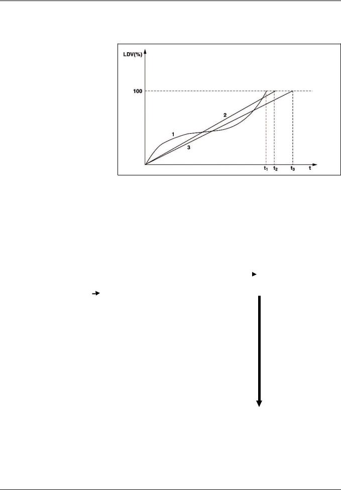
Functions
|
GF00.20>W>3012H |
Life cycle consumption calculation, function |
2.8.11 |
MODEL 963
Life cycle consumption of a maintenance item
1Life cycle consumption after
loading
2Life cycle consumption according to driving time limit
3Life cycle consumption after travel distance limitation
LDV (%) Life cycle consumption
tTime
|
t1 |
Time «100% LDV according to |
|
load» |
|
|
t2 |
Time «100% LDV according to |
|
driving time limit» |
|
|
t3 |
Time «100% LDV according to |
|
distance limit» |
W00.20>1040>05
|
INPUT DATA |
Calculation of life cycle consumption |
OUTPUT DATA |
|||
|
f Operating oil temperatures of |
f Life cycle consumption based on the vehicle load for |
f Life cycle consumption based |
|||
|
major assemblies |
A. directly measured maintenance items (brake linings, air |
on the load |
|||
|
f Brake lining thickness of front and |
filter) |
f Life cycle consumption based |
|||
|
rear axle |
Calculation with linear or nonlinear calculation instruction |
on the time limitation |
|||
|
f Air filter contamination |
as a function of the wear variable. |
f Life cycle consumption based |
|||
|
f Air drier condensation level |
B. Accumulating maintenance items (operation oils) |
on the travel distance |
|||
|
f Brake wear ratio |
Calculation with empirical calculation instructions |
limitation |
|||
|
f Operating time |
dependent on: |
f Life cycle consumption based |
|||
|
f Total time |
> Correction factors for temperature, load, rotational |
on operating |
|||
|
f Distance |
speed, cold start increment |
||||
|
f Number of crankshaft revolutions |
> Quality factors for oil, fuel, mechanical components |
||||
|
f Engine speed |
f Time>based servicing scheme (e.g. lubrication of steering |
||||
|
f Moderate engine speed |
knuckles) |
||||
|
f Average major assemblies |
f Life cycle consumption based on the drive time limit |
||||
|
temperature |
f Life cycle consumption based on the travel distance |
||||
|
f Average outside air temperature |
limitation |
||||
|
f Diesel particulate filter soiling |
f Life cycle consumption based on operating time |
||||
|
f Vehicle speed |
|||||
Æ for forecasting
Forecasting uses the highest value.
|
i Electronic systems, Actros, model 963 > 09/2011 > |
35 |
– This printout will not be recorded by the update service. Status: 09 / 2011 –

Functions
General information
The life cycle consumption calculation provides information on the degree to which the workshop equipment is worn out, and which one should be replaced or repaired during maintenance.
The life cycle consumption calculation determines 4 life cycle consumption values, which are calculated anew during each calculation cycle:
fLife cycle consumption based on vehicle load, based on calculation method for:
>directly measured maintenance items and
>accumulating maintenance items.
fLife cycle consumption based on the drive time limit,
fLife cycle consumption based on the travel distance limitation,
fLife cycle consumption based on operating time,
The workshop equipment is worn out if a life cycle consumption of 100% is reached.
An exception is the time>based servicing scheme, which has fixed maintenance intervals that are independent from loads and driving distance.
The life cycle consumption is the basis for forecasting.
i Very precise, earlier prognoses are possible in the event of regular operations in regard to loads and driving distance over a long period of time. If operations vary greatly, the prognosis variation is higher. The forecasts become increasingly more accurate as total vehicle operating time increases.
Once the four life cycle consumption values have been evaluated, the maintenance system (WS) provides the highest value as a forecasting life cycle parameter.
|
Central gateway control unit (CGW), |
A2 |
Page 333 |
|
|
component description |
|||
36
– This printout will not be recorded by the update service. Status: 09 / 2011 –

Functions
|
GF26.21>W>0002H |
Transmission automation, function |
2.8.11 |
TRANSMISSION 715 in MODEL 963 with CODE (G5G) Mercedes PowerShift 3
TRANSMISSION 715 in MODEL 964 with CODE (G5G) Mercedes PowerShift 3
|
W26.21>1121>79 |
|||||
|
A1 |
Instrument cluster (ICUC) control unit |
B18 |
Travel and speed sensor |
LIN 3 |
Multifunction control lever>LIN on |
|
A2 |
Central gateway control unit (CGW) |
B501 |
Main shaft rpm sensor |
the right |
|
|
A3 |
Drive control (CPC) control unit |
B502 |
Countershaft rpm sensor |
LIN 7 |
Button group LIN |
|
A4 |
Engine management control unit |
B503 |
Clutch travel sensor |
S23 |
Right multifunction control lever |
|
(MCM) |
B504 |
Range group travel sensor |
S110 |
Left multifunction steering wheel |
|
|
A5 |
Transmission control (TCM) control |
B505 |
Transmission oil temperature |
button group |
|
|
unit |
sensor |
S111 |
Right multifunction steering wheel |
||
|
A43 |
Modular switch panel (MSF) control |
CAN 2 |
Interior CAN |
button group |
|
|
unit |
CAN 3 |
Frame CAN |
Y900 |
Transmission positioner |
|
|
CAN 4 |
Drive train CAN |
1General
With transmission automation there a convenience shifting system available over which gear selection as well as declutching and engaging of the clutch take place automatically. It contains a fully automated manual transmission, based on a constant>mesh transmission, with automated clutch operating system. The clutch operation takes place over a pneumatically actuated centrally located clutch operator.
Synchronization does not take place via a blocking synchronization as on a synchromesh transmission but is realized instead by braking or accelerating the countershaft in a controlled manner. As a result can be widened for the same dimensions of the transmission gears and thus higher torques and outputs transmitted. Passive safety is also increased due to reducing the
burden for the driver.
>>>>>>>>>>>>>>>>>>>>>>>>>>>>>>>>>>>>>>>>>>>>>>>>>>>>>>>>>>>>>>>>>>>>>>>>>>>>>>>>>>>>>>>>>
Optimum gear selection supports an economic and fuel>saving driving style. All the shift operations take place in the optimum rpm range, minimizing wear on the transmission and engine.
Faults during shifting are ruled out and it is no longer possible to over rev the engine. After switching on the ignition the automatic mode of transmission automation is always activated irrespective of which mode was last selected (manual or automatic). The option of activating a manual or automatic shift mode with the transmission mode button (M/A) (S23 s3) on the RH multifunction control lever (S23) has been retained. 12 forwards gears, 4 reverse gears and neutral can be engaged.
>>>>>>>>>>>>>>>>>>>>>>>>>>>>>>>>>>>>>>>>>>>>>>>>>>>>>>>>>>>>>>>>>>>>>>>>>>>>>>>>>>>>>>>>>
|
i Electronic systems, Actros, model 963 > 09/2011 > |
37 |
– This printout will not be recorded by the update service. Status: 09 / 2011 –
![]()
Functions
2Changes compared with the previous transmission
generation
fThe transmission positioner (Y900) includes:
>all solenoid valves for controlling the clutch, gear, gate, split, countershaft brake and range group
>travel sensors for gear, gate and split
fa pressed down clutch operation due to the pneumatic central clutch release bearing
>>>>>>>>>>>>>>>>>>>>>>>>>>>>>>>>>>>>>>>>>>>>>>>>>>>>>>>>>>>>>>>>>>>>>>>>>>>>>>>>>>>>>>>>>
3Transmission modes and driving functions
Transmission automation offers the following operating modes:
fAutomatic transmission mode with a driving specific shift program (automatic operation)
fManual transmission mode (manual operation)
fBack>up mode (backup drive mode) includes the additional function «Towing».
Further driving functions include:
fEco>roll mode, in certain driving situations for supporting a fuel>saving driving style through automatic shifting into the transmission neutral position when the accelerator is not actuated
fCrawl function, for automatic starting moving when releasing the service brake and freewheeling without actuating the accelerator pedal
fRocking mode, for rocking the vehicle out of an off>road
recess
>>>>>>>>>>>>>>>>>>>>>>>>>>>>>>>>>>>>>>>>>>>>>>>>>>>>>>>>>>>>>>>>>>>>>>>>>>>>>>>>>>>>>>>>>
4Components of the transmission automation
4.1Transmission (TCM) control unit (A5)
The transmission (TCM) control unit (A5) is the central control unit for the transmission and the clutch. It contains the software modules for controlling the transmission and clutch actors.
The following sensor signals are read in directly amongst others:
fCountershaft rpm sensor (B502)
fTransmission oil temperature sensor (B505)
fMain shaft rpm sensor (B501)
4.2Transmission positioner (Y900)
The transmission positioner (Y900) combines the following components into one unit:
fGear cylinder
fGear cylinder travel sensor (Y900 b2)
>>>>>>>>>>>>>>>>>>>>>>>>>>>>>>>>>>>>>>>>>>>>>>>>>>>>>>>>>>>>>>>>>>>>>>>>>>>>>>>>>>>>>>>>>
4.3Splitter group shift cylinder
The splitter group shift cylinder is integrated into the front part of the transmission housing.
4.4Range group module
The range group module combines the following components into a unit:
fRange group shift cylinder
fRange group travel sensor (B504)
>>>>>>>>>>>>>>>>>>>>>>>>>>>>>>>>>>>>>>>>>>>>>>>>>>>>>>>>>>>>>>>>>>>>>>>>>>>>>>>>>>>>>>>>>
fRetract gear cylinder solenoid valve (Y900 y9)
fExtend gear cylinder solenoid valve (Y900 y8)
fGate cylinder
fGate cylinder travel sensor (Y900 b3)
fRetract gate cylinder solenoid valve (Y900 y11)
fExtend gate cylinder solenoid valve (Y900 y10)
fRetract splitter group solenoid valve (Y900 y7)
fExtend splitter group solenoid valve (Y900 y6)
fSlowly close clutch solenoid valve (Y900 y1)
fSlowly open clutch solenoid valve (Y900 y2)
fQuickly close clutch solenoid valve (Y900 y3)
fQuickly open clutch solenoid valve (Y900 y4)
fRetract range group solenoid valve (Y900 y12)
fExtend range group solenoid valve (Y900 y13)
fCountershaft brake solenoid valve (Y900 y5)
fSplitter group travel sensor (Y900 b1)
>>>>>>>>>>>>>>>>>>>>>>>>>>>>>>>>>>>>>>>>>>>>>>>>>>>>>>>>>>>>>>>>>>>>>>>>>>>>>>>>>>>>>>>>>
4.5Pneumatic central clutch release bearing
The pneumatic central clutch release bearing directly actuates the mechanical clutch components, takes on disengaging the clutch and engaging the clutch and contains the clutch travel sensor (B503).
4.6Right multifunction control lever (S23)
The RH multifunction control lever (S23) transmits the shift
commands to the drive control (CPC) control unit (A3).
>>>>>>>>>>>>>>>>>>>>>>>>>>>>>>>>>>>>>>>>>>>>>>>>>>>>>>>>>>>>>>>>>>>>>>>>>>>>>>>>>>>>>>>>>
38
– This printout will not be recorded by the update service. Status: 09 / 2011 –

Functions
5The following components support during transmission automation
5.1Engine management (MCM) control unit (A4)
The engine management (MCM) control unit (A4) includes the software module for torque and rotational speed actuation of the engine and therefore also implements requests from other control units on the rotational speed and torques for switching, starting off and stopping.
5.2Drive control (CPC) control unit (A3)
The drive control (CPC) control unit (A3) is modular in design and it contains the following software modules:
fSoftware module for drive control; it comes with extended functions (e.g. cruise control etc.)
fSoftware module for automatic gear selection
>>>>>>>>>>>>>>>>>>>>>>>>>>>>>>>>>>>>>>>>>>>>>>>>>>>>>>>>>>>>>>>>>>>>>>>>>>>>>>>>>>>>>>>>>
5.3Modular switch panel (MSF) control unit (A43)
The modular switch panel (MSF) control unit (A43) reads in the operation of the back>up mode via the left multifunction steering wheel button group (S110) or the right multifunction steering wheel button group (S111).
5.4Tachograph (TCO) (P1)
The tachograph (TCO) (P1) reads in the way and speed sensor (B18) and evaluates its signal.
5.5IC control unit (ICUC) (A1)
The IC (ICUC) control unit (A1) shows the driver information over
the multifunction display (A1 p1).
>>>>>>>>>>>>>>>>>>>>>>>>>>>>>>>>>>>>>>>>>>>>>>>>>>>>>>>>>>>>>>>>>>>>>>>>>>>>>>>>>>>>>>>>>
6Transmission cooling (for code N6Z)
A thermostatically regulated transmission cooling with the following components is used as special equipment:
fTransmission cooler with a transmission cooling fan (M19) (located in the direction of travel on the right, next to the cooling module)
fTransmission oil lines
fThermostat element with spring from the shape memory alloy (FGL)
For transmission oil temperatures above 80∞C the spring force of the spring closes the cooler protection valve (bypass). The transmission oil flows through the transmission cooler and is cooled by the airstream.
If the transmission oil temperature increases further, the transmission cooling fan (M19) located on the transmission cooler is switched on from 90∞C over the SCA (SCA) control unit (A7).
For transmission oil temperatures below 80∞C the spring opens the cooler protection valve. The transmission oil flows uncooled over the bypass back into the transmission.
i In the case of an excessively high transmission oil pressure the cooler and the transmission protection valve open and allow the oil to flow uncooled over a bypass back into the transmission.
|
Overall network for transmission |
Page 40 |
||
|
automation |
|||
|
Operation, function |
Page 41 |
||
|
Driver information, function |
Page 44 |
||
|
Transmission mode, function |
Page 45 |
||
|
Shifting the transmission, function |
Page 46 |
||
|
Controlling the clutch, function |
Page 52 |
||
|
Countershaft brake, function |
Page 54 |
||
|
i Electronic systems, Actros, model 963 > 09/2011 > |
39 |
– This printout will not be recorded by the update service. Status: 09 / 2011 –

Functions
GF26.21>W>0002>01H Overall network for transmission automation
|
W26.00>1032>79 |
|||||
|
A1 |
Instrument cluster (ICUC) control |
A10c |
Electronic brake system (EBS) |
S23 |
Right multifunction control lever |
|
unit |
control unit |
S110 |
Left multifunction steering wheel |
||
|
A2 |
Central gateway control unit (CGW) |
A43 |
Modular switch panel (MSF) |
button group |
|
|
A3 |
Drive control (CPC) control unit |
control unit |
S111 |
Right multifunction steering wheel |
|
|
A4 |
Engine management control unit |
CAN 2 |
Interior CAN |
button group |
|
|
(MCM) |
CAN 3 |
Frame CAN |
Z1 |
Cab instrument panel CAN bus star |
|
|
A5 |
Transmission control (TCM) control |
CAN 4 |
Drive train CAN |
point |
|
|
unit |
LIN 3 |
Multifunction control lever>LIN on |
Z3 |
Frame CAN bus star point |
|
|
A10b |
Electronic brake system (EBS) control |
the right |
Z4 |
Drive CAN bus star point |
|
|
unit |
LIN 7 |
Button group LIN |
|||
|
P1 |
Tachograph (TCO) |
40
– This printout will not be recorded by the update service. Status: 09 / 2011 –

Functions
|
GF26.21>W>3003H |
Operation, function |
2.8.11 |
TRANSMISSION 715 in MODEL 963 with CODE (G5G) Mercedes PowerShift 3
TRANSMISSION 715 in MODEL 964 with CODE (G5G) Mercedes PowerShift 3
A3 Drive control (CPC) control unit
A5 Transmission control (TCM) control unit
CAN 4 Drive train CAN
LIN 3 Multifunction control lever>LIN on the right
S23 Right multifunction control lever S23s1 Transmission position switch
(D/N/R)
S23s2 Gearshift paddle (+/>)
S23 s3 Transmission mode (M/A) button
W26.21>1119>06
Normal operation
The shift commands are recorded over in the integral controls in the RH multifunction control lever (S23):
fTransmission position (D/N/R) switch (S23 s1)
fGearshift paddle (+/>) (S23 s2)
fTransmission mode (M/A) button (S23 s3)
The drive control (CPC) control unit (A3) reads in the shift signals from the RH multifunction control lever (S23) via the RH multifunction control lever LIN (LIN 3), evaluates them and sends appropriate CAN messages to the transmission (TCM) control unit (A5) via the drive train CAN (CAN 4).
Twelve forwards gears, 4 reverse gears and neutral can be engaged.
>>>>>>>>>>>>>>>>>>>>>>>>>>>>>>>>>>>>>>>>>>>>>>>>>>>>>>>>>>>>>>>>>>>>>>>>>>>>>>>>>>>>>>>>>
Automatic operation
(the optimal gear (the required gear specification) is determined by the drive control (CPC) control unit (A3))
Gear selection is dependent on the following influencing variables:
fGround speed (only relevant for the start>off gear)
fAccelerator pedal position (specified torque)
fLoad condition of engine
fOperating point of the target gear
fStarting speed of the transmission
fOperation of the permanent brake
fLoad condition of the vehicle
fShift program
fLay of the land for the driving lane
Manual mode
Difference to automatic mode:
fThe shifting operations must be initiated by the driver, that is the driver determines the shift point and shift direction.
fThe kickdown function is not available.
>>>>>>>>>>>>>>>>>>>>>>>>>>>>>>>>>>>>>>>>>>>>>>>>>>>>>>>>>>>>>>>>>>>>>>>>>>>>>>>>>>>>>>>>>
|
i Electronic systems, Actros, model 963 > 09/2011 > |
41 |
– This printout will not be recorded by the update service. Status: 09 / 2011 –

Functions
Operation of the driving functions
The driving functions assist the driver in daily driving to drive with a more fuel economy. They increase the ride comfort and support him in difficult situations.
Selectable driving functions are:
fEcoRoll mode, in certain driving situations for supporting a fuel>saving driving style through automatic shifting into the transmission neutral position «N» when the accelerator is not actuated
fRocking mode, for rocking the vehicle out of an off>road recess
fCrawl mode, for automatic starting moving when releasing the service brake and continued crawling without actuating
the accelerator pedal.
>>>>>>>>>>>>>>>>>>>>>>>>>>>>>>>>>>>>>>>>>>>>>>>>>>>>>>>>>>>>>>>>>>>>>>>>>>>>>>>>>>>>>>>>>
Function sequence
If the pre>conditions are fulfilled then the drive control (CPC) control unit (A3) requests the neutral position from the transmission (TCM) control unit (A5) via the drive train CAN (CAN 4). The transmission (TCM) control unit (A5) actuates the transmission positioner (Y900) to open the clutch. After successful opening of the clutch, read in over the clutch position sensor (B503), the transmission positioner (Y900) is actuated to engage neutral. After ending the switching the transmission (TCM) control unit (A5) transmits the engaged neutral to the drive control (CPC) control unit (A3) via the drive train CAN (CAN 4).
i Based on the reduced engine speed a somewhat lower steering assist can occur and therefore greater steering forces in certain driving situations, for example on slightly curved downslopes. The operation or road safety is not endangered by this.
>>>>>>>>>>>>>>>>>>>>>>>>>>>>>>>>>>>>>>>>>>>>>>>>>>>>>>>>>>>>>>>>>>>>>>>>>>>>>>>>>>>>>>>>>
Function sequence
The crawl function consists of 2 parts:
fIn gears 1 to 6, R1 and R2, self>actuated starting crawling by releasing the service brake (only for an active crawl function)
fIn gears 1 to 6, R1 and R2 further crawling (=freewheeling)
for a non>actuated accelerator pedal
The driving off dosing occurs for first driving off over the accelerator pedal. The system is taught in in the process to the torque prescribed by the driver. After the first «real» driving determination of the crawling torque depends on the determined vehicle mass and incline in the driving lane.
i If driving with a trailer is recognized over the trailer recognition the mass and incline dependent crawling torque is reset in the drive control (CPC) control unit (A3) and teaching in
occurs again during first driving off.
>>>>>>>>>>>>>>>>>>>>>>>>>>>>>>>>>>>>>>>>>>>>>>>>>>>>>>>>>>>>>>>>>>>>>>>>>>>>>>>>>>>>>>>>>
EcoRoll mode
Preconditions
fEcoRoll function activated
fGround speed was > 35 km/h and is > 25 km/h (hysteresis)
fAccelerator not operated
fService brake or permanent brake not actuated
fDriver assistance systems not in control mode
fBrake assistant systems not in control mode
fPower take>off switched off
fVariable speed limiter maximum speed not exceeded
fCC speed tolerance not exceeded
>>>>>>>>>>>>>>>>>>>>>>>>>>>>>>>>>>>>>>>>>>>>>>>>>>>>>>>>>>>>>>>>>>>>>>>>>>>>>>>>>>>>>>>>>
Crawl mode
The crawl function is always switched on after an engine start and is activated after first moving off.
The crawl function is deactivated under the following conditions:
fThe crawl function is switched off over the IC (ICUC) control unit (A1)
fThe transmission in neutral for longer than 2 s
fThe parking brake is tightened
fThe rocking mode is activated
fDriver assistance systems switch into control mode
fIdle speed > 700 rpm
fThreat of clutch overloading
fAn excessively high air drag and rolling resistance
fAn excessively high tire grip
i The crawl function is similar in its behavior to an automatic torque converter. Since the function is realized over the clutch the function is not wear>free and the vehicle in the slip range of the
clutch is not capable of permanently crawling.
>>>>>>>>>>>>>>>>>>>>>>>>>>>>>>>>>>>>>>>>>>>>>>>>>>>>>>>>>>>>>>>>>>>>>>>>>>>>>>>>>>>>>>>>>
Rocking mode Function sequence
Rocking mode is activated over the rocking mode button (S938). If rocking mode has been activated the transmission control changes from automatic into manual mode.
Accelerator pedal requests are implemented more directly and the clutch is opened more rapidly for a non>actuated accelerator pedal. The clutch is closed quickly again as soon as the accelerator pedal is actuated again. Through repeated actuation and release of the accelerator pedal can put the vehicle into a rocking mode condition and in this way can rock the vehicle free out if a hollow.
>>>>>>>>>>>>>>>>>>>>>>>>>>>>>>>>>>>>>>>>>>>>>>>>>>>>>>>>>>>>>>>>>>>>>>>>>>>>>>>>>>>>>>>>>
42
– This printout will not be recorded by the update service. Status: 09 / 2011 –

Functions
Back>up mode
Back>up mode represents a last emergency function for engaging gears for a vehicle standstill. The operating commands for navigation are entered in the menu tree multifunction display (A1 p1) in the IC (ICUC) control unit (A1) over the LH multifunction steering wheel button group (S110) and the RH multifunction steering wheel button group (S111).
The modular switch panel (MSF) control unit (A43) reads in the switching commands from the LH multifunction steering wheel button group (S110) and the RH multifunction steering wheel button group (S111), evaluates them and transmits appropriate CAN messages via the interior CAN (CAN 2), the central gateway (CGW) control unit (A2) and the frame CAN (CAN 3) to the drive control (CPC) control unit (A3).
The drive control (CPC) control unit (A3) evaluates the switching request from the driver, determines the targeted gear to be switched and, for release, transmits appropriate CAN messages via the drive train CAN (CAN 4) to the transmission (TCM) control unit (A5).
The following switching positions can be selected in back>up mode:
fR (for reverse gear)
fN (for neutral)
fD1 (for 2nd gear)
fD2 (for 6th gear)
fTowing (for the towing mode)
The actuation of the clutch is controlled automatically as long as no malfunction is present. A malfunction would result in automatic clutch operation being disabled.
i If gear selection was not enabled, a shift to «neutral» is always enabled.
|
Instrument cluster control unit (ICUC), |
A1 |
Page 331 |
|
|
component description |
|||
|
Component description for central |
A2 |
Page 333 |
|
|
gateway control unit (CGW) |
|||
|
Component description for drive control |
A3 |
Page 334 |
|
|
(CPC) control unit |
|||
|
Component description for transmission |
A5 |
Page 337 |
|
|
control (TCM) control unit |
|||
|
Component description for modular switch |
A43 |
Page 370 |
|
|
panel control unit (MSF) |
|||
|
Component description for right |
S23 |
Page 463 |
|
|
multifunction control lever |
|||
|
Component description for multifunction |
S110, S111 |
Page 469 |
|
|
steering wheel |
|||
|
i Electronic systems, Actros, model 963 > 09/2011 > |
43 |
– This printout will not be recorded by the update service. Status: 09 / 2011 –

Functions
|
GF26.21>W>3005H |
Driver information, function |
2.8.11 |
TRANSMISSION 715 in MODEL 963 with CODE (G5G) Mercedes PowerShift 3
TRANSMISSION 715 in MODEL 964 with CODE (G5G) Mercedes PowerShift 3
A1 Instrument cluster (ICUC) control unit
A1 p1 Multifunction display
A3 Drive control (CPC) control unit
A5 Transmission control (TCM) control unit
B50 Center speaker CAN 3 Frame CAN CAN 4 Drive train CAN
W26.21>1118>76
Displaying shift status
The drive control (CPC) control unit (A3) transmits the information for indication of the switching condition to the IC (ICUC) control unit (A1) via the frame CAN (CAN 3).
To do this the transmission (TCM) control unit (A5) permanently transmits the CAN messages with information about the condition of the transmission (for example the engaged gear, the possible gear) to the drive control (CPC) control unit (A3) via the drive train CAN (CAN 4). Before execution of the shift operation the drive control (CPC) control unit (A3) transmits the targeted gear request (determined from the automatic gear selection or the gear selected by the driver) to the transmission (TCM) control unit (A5). The transmission (TCM) control unit (A5) transmits the confirmed targeted gear and the engaged current gear to the drive control
(CPC) control unit (A3) .
>>>>>>>>>>>>>>>>>>>>>>>>>>>>>>>>>>>>>>>>>>>>>>>>>>>>>>>>>>>>>>>>>>>>>>>>>>>>>>>>>>>>>>>>>
Emit warning tones acoustically
The transmission (TCM) control unit (A5) transmits CAN messages with information concerning the condition of the transmission (for example on the switched gear, the possible gear, temperature of the transmission oil) to the drive control (CPC) control unit (A3) via the drive train CAN (CAN 4).
The IC (ICUC) control unit (A1) receives the CAN messages and generates the following displays in the multifunction display (A1 p1):
fdisplay of the direction of travel and / or the engaged gear
fdisplay of the gearshift recommendation or to engaged gear
fdisplay of the transmission mode
The previous display is retained during the shift operation. The current display only takes place when the shift operation is concluded.
i During the teach>in process appropriate CAN messages are transmitted with information for display of the active teach>in process. Also in back>up mode all CAN messages are transmitted, as in normal mode, via the drive control (CPC) control unit (A3) and the frame CAN (CAN 3) to the IC (ICUC) control unit (A1).
>>>>>>>>>>>>>>>>>>>>>>>>>>>>>>>>>>>>>>>>>>>>>>>>>>>>>>>>>>>>>>>>>>>>>>>>>>>>>>>>>>>>>>>>>
The drive control (CPC) control unit (A3) decides over a warning emission to the driver. If a warning emission is necessary, the drive control (CPC) control unit (A3) transmits an appropriate CAN message with the information for output of warning tones to the IC (ICUC) control unit (A1) via the frame CAN (CAN 3).
The IC (ICUC) control unit (A1) receives the CAN messages from the drive control (CPC) control unit (A3) and generates acoustic messages whose output takes place over the center speaker (B50).
|
Component description for instrument |
A1 |
Page 331 |
|
|
cluster control unit (ICUC) |
|||
|
Component description drive control (CPC) |
A3 |
Page 334 |
|
|
control unit |
|||
|
Component description for transmission |
A5 |
Page 337 |
|
|
control (TCM) control unit |
|||
44
– This printout will not be recorded by the update service. Status: 09 / 2011 –

Functions
|
GF26.21>W>3007H |
Transmission mode, function |
2.8.11 |
TRANSMISSION 715 in MODEL 963 with CODE (G5G) Mercedes PowerShift 3
TRANSMISSION 715 in MODEL 964 with CODE (G5G) Mercedes PowerShift 3
General information
One can select between a manual transmission mode (manual operation) or an automatic transmission mode (automatic operation). In automatic operation there is a standard switching program (A) and either the shift program (A power) or the shift program
(A economy) available depending on the vehicle and transmission design.
Automatic transmission mode
The transmission automation is fitted with a standard shift program:
fA, with kickdown, accelerator pedal curve standard, CC standard, maximum speed of 89.8 km/h, function EcoRoll which can be switched off
The driving specific shift programs have the following significant properties:
fA power, switchings take place at an about 100 rpm higher rotational speed in comparison with a standard shift program and dynamic clutch matching for driving off
fA economy, no kickdown possible, EcoRoll cannot be switched off, maximum speed of 85 km/h, accelerator pedal curve and max. engine torque lowered, CC Softcruise
i Selection of the automatic transmission mode takes place over the transmission mode button (M/A) (S23 s3) on the RH multifunction control lever (S23).
Manual transmission mode
In manual transmission mode the shift operations are initiated by the driver over it. This means that the driver determines the shift point and the switching direction. The kickdown function is not available.
|
Component description for right |
S23 |
Page 463 |
|
|
multifunction control lever |
|||
|
i Electronic systems, Actros, model 963 > 09/2011 > |
45 |
– This printout will not be recorded by the update service. Status: 09 / 2011 –

Functions
|
GF26.20>W>3007H |
Shifting the transmission, function |
2.8.11 |
TRANSMISSION 715 in MODEL 963 with CODE (G5G) Mercedes PowerShift 3
TRANSMISSION 715 in MODEL 964 with CODE (G5G) Mercedes PowerShift 3
|
W26.21>1123>09 |
|||||
|
Schematic representation |
|||||
|
1 |
Gate cylinder |
A3 |
Drive control (CPC) control unit |
B504 |
Range group travel sensor |
|
2 |
Range group shift cylinder |
A4 |
Engine management (MCM) |
CAN 2 |
Interior CAN |
|
3 |
Gear cylinder |
control unit |
CAN 3 |
Frame CAN |
|
|
4 |
Splitter group shift cylinder |
A5 |
Transmission control (TCM) |
CAN 4 |
Drive train CAN |
|
6 |
Countershaft brake |
control unit |
LIN 3 |
Multifunction control lever>LIN on |
|
|
6.1 |
Mechanical vent valve |
A43 |
Modular switch panel (MSF) |
the right |
|
|
7 |
Pneumatic central clutch release |
control unit |
LIN 7 |
Button group LIN |
|
|
bearing |
B18 |
Travel and speed sensor |
S23 |
Right multifunction control lever |
|
|
B501 |
Main shaft rpm sensor |
S110 |
Left multifunction steering wheel |
||
|
A1 |
Instrument cluster (ICUC) control |
B502 |
Countershaft rpm sensor |
button group |
|
|
unit |
B503 |
Clutch travel sensor |
S111 |
Right multifunction steering wheel |
|
|
A2 |
Central gateway control unit (CGW) |
button group |
|
Y900 b1 |
Splitter group travel sensor |
Y900 y4 |
Clutch quick opening solenoid |
Y900 y9 ‘Retract’ gear cylinder solenoid |
|
|
Y900 b2 |
Gear cylinder travel sensor |
valve |
valve |
||
|
Y900 b3 |
Gate cylinder travel sensor |
Y900 y5 |
Countershaft brake solenoid |
Y900 y10 |
‘Extend’ gate cylinder solenoid |
|
Y900 y1 |
Clutch slow closing solenoid valve |
valve |
valve |
||
|
Y900 y2 |
Clutch slow opening solenoid valve |
Y900 y6 |
‘Extend’ splitter group solenoid |
Y900 y11 |
‘Retract’ gate cylinder solenoid |
|
Y900 y3 |
Clutch quick closing solenoid valve |
valve |
valve |
||
|
Y900 y7 |
‘Retract’ splitter group solenoid |
Y900 y12 |
‘Retract’ range group solenoid |
||
|
valve |
valve |
||||
|
Y900 y8 |
‘Extend’ gear cylinder solenoid |
Y900 y13 |
‘Extend’ range group solenoid |
||
|
valve |
valve |
46
– This printout will not be recorded by the update service. Status: 09 / 2011 –

Functions
1General
The transmission control (TCM) control unit (A5) is, as the interface to the transmission, the central control electronics for shift operation of a gear and actuation of the clutch.
It controls the entire shift operation and in the process performs the following tasks:
fSwitching the switching groups of the transmission
fMeasuring and evaluating the shift status and operating condition of the transmission
fMeasuring and evaluating the shift status and operating condition of the clutch
fRegulation and positioning of the clutch
>>>>>>>>>>>>>>>>>>>>>>>>>>>>>>>>>>>>>>>>>>>>>>>>>>>>>>>>>>>>>>>>>>>>>>>>>>>>>>>>>>>>>>>>>
3Shifting the transmission
Actuation of the components cylinder valve gear extend solenoid (Y900 y8), gear cylinder retract solenoid valve (Y900 y9), splitter group extend solenoid valve (Y900 y6), splitter group retract solenoid valve (Y900 y7), range group retract solenoid valve (Y900 y12), range group extend solenoid valve (Y900 y13), gate cylinder extend solenoid valve (Y900 y10), gate cylinder retract solenoid valve (Y900 y11) takes place over electrical shift signals from the transmission control (TCM) control unit (A5).
The sequence of actuation is carried out as per a specified sequence corresponding to the gear to be shifted. The solenoid valves control the admission and release of air into/out of the working spaces of the associated gate shift cylinder (1), range group shift cylinder (2), gear cylinder (3) and splitter group shift cylinder (4). In the process their piston rods assume a defined position and operate the associated shift mechanism for shifting
the splitter, range group, gear and gate.
>>>>>>>>>>>>>>>>>>>>>>>>>>>>>>>>>>>>>>>>>>>>>>>>>>>>>>>>>>>>>>>>>>>>>>>>>>>>>>>>>>>>>>>>>
3.3Shifting the splitter group
The splitter group is switched through actuation of the splitter group extend solenoid valve (Y900 y6) or splitter group retract solenoid valve (Y900 y7).
3.4Shifting the gate
The gate is switched through actuation of the gate cylinder retract solenoid valve (Y900 y11).
i There is a spring in the shift mechanism to reset the transmission shift rod. This ensures that there is the necessary return force present for a non> actuated gate cylinder retract solenoid valve (Y900 y11). The return force of the spring is also supported as required through actuation of the gate cylinder extended solenoid valve (Y900 y10).
>>>>>>>>>>>>>>>>>>>>>>>>>>>>>>>>>>>>>>>>>>>>>>>>>>>>>>>>>>>>>>>>>>>>>>>>>>>>>>>>>>>>>>>>>
2CAN communication
The transmission control (TCM) control unit (A5) which is located above the overall network is in constant data exchange with other control units which provide switching relevant data.
It is in direct connection with the drive control (CPC) control unit (A3) and the engine management (MCM) control unit (A4) via the drive train CAN (CAN 4). Also requests from the transmission control (TCM) control unit (A5) to other control units (e.g. rotational speed requests to the engine) are transmitted via the drive train CAN (CAN 4).
>>>>>>>>>>>>>>>>>>>>>>>>>>>>>>>>>>>>>>>>>>>>>>>>>>>>>>>>>>>>>>>>>>>>>>>>>>>>>>>>>>>>>>>>>
3.1Controlling the clutch
Actuation of the components clutch slow close solenoid valve (Y900 y1), clutch slow open solenoid valve (Y900 y2), clutch rapid close solenoid valve (Y900 y3), clutch rapid open solenoid valve (Y900 y4) occurs over electrical shift signals from the transmission control (TCM) control unit (A5).
The solenoid valves control the aeration and ventilation of the pneumatic central clutch release bearing (7). The pneumatic central clutch release bearing (7) opens or closes the clutch or regulates the clutch at a particular position.
3.2Switch the range group
Condition: the neutral position of gear cylinder (3) was detected. The range group is switched through actuation of the range group retract solenoid valve (Y900 y12) or the range group extend solenoid valve (Y900 y13).
>>>>>>>>>>>>>>>>>>>>>>>>>>>>>>>>>>>>>>>>>>>>>>>>>>>>>>>>>>>>>>>>>>>>>>>>>>>>>>>>>>>>>>>>>
3.5Switch the gear
The gears are switched through actuation of the gate cylinder extend solenoid valve (Y900 y8) or the gate cylinder retract solenoid valve (Y900 y9). The shift operation starts from the neutral position.
i The rotational speed of the countershaft must be aligned with the rotational speed of the main shaft before switching the gear. This occurs for upshifting through actuation of the countershaft brake solenoid valve (Y900 y5) as well as for downshifting through raising the engine speed for a closed clutch.
3.6Shifting gears in towing mode
Towing mode is only possible in back>up mode and if the electrical and pneumatic components are functioning correctly. Towing mode comprises automatic shifting of the high>speed range
group and of the neutral position.
>>>>>>>>>>>>>>>>>>>>>>>>>>>>>>>>>>>>>>>>>>>>>>>>>>>>>>>>>>>>>>>>>>>>>>>>>>>>>>>>>>>>>>>>>
|
i Electronic systems, Actros, model 963 > 09/2011 > |
47 |
– This printout will not be recorded by the update service. Status: 09 / 2011 –
 Loading…

Руководство по эксплуатации, техническому обслуживанию и ремонту грузовых автомобилей Mercedes-Benz Actros 1996-2007 годов выпуска.
- Автор: —
- Издательство: Диез
- Год издания: —
- Страниц: 704
- Формат: —
- Размер: —
Руководство по эксплуатации, техническому обслуживанию и ремонту грузовых автомобилей Mercedes-Benz Actros третьего поколения 2008-2011 годов выпуска.
- Автор: —
- Издательство: Диез
- Год издания: —
- Страниц: 496
- Формат: —
- Размер: —
Сборник руководств по диагностике, техническому обслуживанию и ремонту автомобиля Mercedes-Benz Actros первого поколения.
- Автор: —
- Издательство: Mercedes-Benz
- Год издания: —
- Страниц: —
- Формат: ISO
- Размер: 653,9 Mb

Руководство по ремонту автомобиля Mercedes-Benz Actros с 2003 года выпуска.
- Автор: —
- Издательство: Терция
- Год издания: —
- Страниц: 218
- Формат: —
- Размер: —
Руководство по эксплуатации, техническому обслуживанию и ремонту автомобиля Mercedes-Benz Actros 1996-2003 годов выпуска в кузовах W950/W952/W953/W954.
- Автор: —
- Издательство: Арго-Авто
- Год издания: —
- Страниц: 800
- Формат: —
- Размер: —
Схемы электрооборудования грузового автомобиля Mercedes-Benz Actros.
- Автор: —
- Издательство: Терция
- Год издания: —
- Страниц: 184
- Формат: —
- Размер: —
Руководство по эксплуатации, техническому обслуживанию и ремонту автомобиля Mercedes-Benz Actros 2003-2011 годов выпуска в кузовах W930/W932/W933/W934.
- Автор: —
- Издательство: Арго-Авто
- Год издания: —
- Страниц: 808
- Формат: —
- Размер: —

Руководство по эксплуатации, техническому обслуживанию и ремонту грузовых автомобилей Mercedes-Benz Actros с 2012 года выпуска.
- Автор: —
- Издательство: Монолит
- Год издания: —
- Страниц: 504
- Формат: —
- Размер: —

Руководство по эксплуатации, техническому обслуживанию и ремонту грузовых автомобилей Mercedes-Benz Actros с 2012 года выпуска.
- Автор: —
- Издательство: Монолит
- Год издания: —
- Страниц: 464
- Формат: —
- Размер: —

Mercedes Actros manual PDF: owner’s, operators, service and maintenance manuals, error codes list, DTC, spare parts manuals & catalogues, wiring diagrams, schematics free download PDF
See also:
| Title | File Size | Download Links |
| Mercedes Benz Actros 2031 S Specifications [PDF] | 555.1kb | Download |
| Mercedes Benz Actros 2648LS 6×4 v3 Specifications [PDF] | 776.8kb | Download |
| Mercedes Benz Actros 3939 K 6×4 39 Specifications [PDF] | 314.7kb | Download |
| Mercedes Benz Actros 4043 S 6×4 33 Specifications [PDF] | 283.5kb | Download |
| Mercedes Benz Actros 4046 S 6×4 33 Specifications [PDF] | 380.1kb | Download |
| Mercedes Benz Actros 4054 S Specifications [PDF] | 604.4kb | Download |
| MERCEDES BENZ Actros ABS EBS Wiring Diagrams [PDF] | 547.9kb | Download |
| Mercedes Benz Actros Brochure [PDF] | 2.5Mb | Download |
| Mercedes Benz Actros MP4 Water Retarder [PDF] | 393.9kb | Download |
| Mercedes Benz Actros Spec Engines Brochure [PDF] | 3.4Mb | Download |
| Mercedes Benz Actros Specifications [PDF] | 4.6Mb | Download |
| Mercedes Benz New Actros MP2 Training Manual [PDF] | 6.7Mb | Download |
| Mercedes-Benz 963 / 964 2022 Series Manual [PDF] | 2.3Mb | Download |
| Mercedes-Benz Actros – electronic systems Model 963 [PDF] | 36.2Mb | Download |
| Mercedes-Benz Actros 2017 Operating Instructions Manual [PDF] | 8.1Mb | Download |
| Mercedes-Benz Actros 932314 GS manual PDF [PDF] | 1.9Mb | Download |
| Mercedes-Benz Actros Abs Ebs Schematic Wiring Diagrams [PDF] | 713.2kb | Download |
| Mercedes-Benz Actros GS Service Manual [PDF] | 799kb | Download |
| Mercedes-Benz Actros Manual Oper Cplto [PDF] | 7.5Mb | Download |
| Mercedes-Benz Actros MP II Service Manual [PDF] | 7.9Mb | Download |
| Mercedes-Benz Actros MP4 2020 Driver Familiarisation [PDF] | 1.4Mb | Download |
| Mercedes-Benz Actros Operating Instructions Manual [PDF] | 6Mb | Download |
| Mercedes-Benz Actros, Antos, Arocs Full Service Manual 2014 [PDF] | 18.8Mb | Download |
| Mercedes-Benz Antos 2017 Operating Instructions Manual [PDF] | 8.1Mb | Download |
| Mercedes-Benz Arocs (964) Service Manual [PDF] | 3.9Mb | Download |
| Mercedes-Benz Card Actros Componentes [PDF] | 2.5Mb | Download |
Mercedes Actros User Manual PDF
Manuals for repair, maintenance, and operation of trucks Mercedes Benz Actros (W930 / W932 / W933 / W934) 2003-2011 with diesel engines OM501 V6 12 liters; OM502 V8 16 HP
A heavy truck or tractor driver is driving for a long time. Therefore, the manufacturers of Mercedes-Benz Actros paid special attention to creating a comfortable interior atmosphere. The well-thought-out arrangement of control devices, cozy seats, berths, everything is designed for the convenience of drivers. In addition, German trucks Mercedes Actros are famous for the highest safety, impeccable reliability, and also efficiency. In order for this truck to please you as long as possible with the uninterrupted operation, you need to know and be able to take care of it. To do this, you must have the Mercedes-Benz Actros User Manual. A detailed description of the capabilities, technical characteristics, devices, and rules for the care and operation of the Mercedes-Benz Actros will help you properly care for your truck. It details the control panel, onboard computer, and instrument cluster.
Repair manuals for Mercedes-Benz Actros will acquaint you with methods for diagnosing breakdowns. He will tell you about ways to eliminate them on the way, as well as in garage conditions.
The recommended manuals detail the V6OM 501 12 liters 456 hp diesel engines; V8OM 502, 16 liters, rated at 503 hp. The Mercedes-Benz Actros manuals describe the removal/installation, detailed assembly/dismantling, adjustment, and tuning of these diesel engines. Manual transmission, automatic transmission, transmission, steering, onboard communication systems, heating, air conditioning, control systems, pneumatic lines, axles, driveshaft, exhaust, and brake systems are described in detail.
The system SPA-assistance when driving along a given lane, ABA-distance support, ABS-anti-lock, EBD-distributing brake force, etc., is thoroughly signed. The repair of the cab, its removal and installation, cab suspensions, suspension struts, cab support stabilizers, replacement of floor panels, and much more are signed to the smallest detail.
The electrical equipment of the Mercedes-Benz Actros is presented in detail, accompanied by detailed wiring diagrams, tips, and tricks. Harnesses and, connectors, tightening moments are painted to the smallest detail.
The Mercedes-Benz Actros repair manual describes in detail the operating fluids, lubricants, and necessary spare parts. In addition, preparing the vehicle for driving, starting the engine with an auxiliary battery, towing, etc., are exhaustively described. Mercedes Actros has the most reliable engine capable of winding a million kilometers with proper operation. If the engine of your truck failed earlier than this, then this indicates a ruthless attitude towards your breadwinner.

#image_title
Naturally, the Mercedes-Benz Actros requires regular maintenance. You will find the frequency, schedule, and scope of procedures in the Mercedes Actros manual PDF. The onboard computer of this smart car will tell you, for example, when the oil should be changed. And how to do this, what engine oil to use, you will read in the presented manual. From it you will learn how to change the engine filters or dryer cartridge, how to initialize the control unit or adjust the headlights, and much more. All repair and maintenance procedures are displayed clearly with drawings and photographs. Because of this, you simply cannot have problems with the repair and maintenance of Mercedes-Benz Actros.
The Owner’s User Manual is intended for owners and drivers of Mercedes Actros. In addition, it will help point by point to understand the rather complex electronic control and monitoring system. The need for this manual by representatives of service stations, services and car repair shops is beyond doubt.