- Manuals
- Brands
- Allen-Bradley Manuals
- Controller
- RSLogix 5000 Version 20
Manuals and User Guides for Allen-Bradley RSLogix 5000 Version 20. We have 1 Allen-Bradley RSLogix 5000 Version 20 manual available for free PDF download: Reference Manual

RSLogix 5000
Fuzzy Designer
User Manual

Important User Information Solid state equipment has operational characteristics differing from those of electromechanical equipment. Safety Guidelines for the Application,
Installation and Maintenance of Solid State Controls (publication SGI-1.1 available from your local Rockwell Automation sales office or online at http://literature.rockwellautomation.com) describes some important differences between solid state equipment and hard-wired electromechanical devices. Because of this difference, and also because of the wide variety of uses for solid state equipment, all persons responsible for applying this equipment must satisfy themselves that each intended application of this equipment is acceptable.
In no event will Rockwell Automation, Inc. be responsible or liable for indirect or consequential damages resulting from the use or application of this equipment.
The examples and diagrams in this manual are included solely for illustrative purposes. Because of the many variables and requirements associated with any particular installation, Rockwell Automation, Inc. cannot assume responsibility or liability for actual use based on the examples and diagrams.
No patent liability is assumed by Rockwell Automation, Inc. with respect to use of information, circuits, equipment, or software described in this manual.
Reproduction of the contents of this manual, in whole or in part, without written permission of Rockwell Automation, Inc., is prohibited.
Throughout this manual, when necessary, we use notes to make you aware of safety considerations.
|
Identifies information about practices or circumstances that can cause |
||||||||
|
WARNING |
||||||||
|
an explosion in a hazardous environment, which may lead to personal |
||||||||
|
injury or death, property damage, or economic loss. |
||||||||
|
Identifies information that is critical for successful application and |
||||||||
|
IMPORTANT |
||||||||
|
understanding of the product. |
||||||||
|
Identifies information about practices or circumstances that can lead |
||||||||
|
ATTENTION |
||||||||
|
to personal injury or death, property damage, or economic loss. |
||||||||
|
Attentions help you identify a hazard, avoid a hazard, and recognize |
||||||||
|
the consequence |
||||||||
|
Labels may be on or inside the equipment, for example, a drive or |
||||||||
|
SHOCK HAZARD |
||||||||
|
motor, to alert people that dangerous voltage may be present. |
||||||||
|
Labels may be on or inside the equipment, for example, a drive or |
||||||||
|
BURN HAZARD |
||||||||
|
motor, to alert people that surfaces may reach dangerous |
||||||||
|
temperatures. |
||||||||
Allen-Bradley, ControlLogix, RSLogix 5000, Logix, and RSLinx are trademarks of Rockwell Automation, Inc. Trademarks not belonging to Rockwell Automation are property of their respective companies.

|
Table of Contents |
||
|
Preface |
About This Publication. . . . . . . . . . . . . . . . . . . . . . . . . . . . . |
7 |
|
Who Should Use This Publication. . . . . . . . . . . . . . . . . . . . . |
7 |
|
|
Conventions . . . . . . . . . . . . . . . . . . . . . . . . . . . . . . . . . . . . |
7 |
|
|
Chapter 1 |
||
|
Get Started with FuzzyDesigner |
Introduction . . . . . . . . . . . . . . . . . . . . . . . . . . . . . . . . . . . . |
9 |
|
Understanding FuzzyDesigner . . . . . . . . . . . . . . . . . . . . . . . |
9 |
|
|
Fuzzy Logic and Fuzzy Control Essentials . . . . . . . . . . . . |
12 |
|
|
Potential Use of Fuzzy Logic . . . . . . . . . . . . . . . . . . . . . . |
16 |
|
|
Specifications and Features . . . . . . . . . . . . . . . . . . . . . . . |
18 |
|
|
Integrated Design Environment (IDE) screen captures . . . . . . |
22 |
|
|
Chapter 2 |
||
|
FuzzyDesigner Component Library |
Introduction . . . . . . . . . . . . . . . . . . . . . . . . . . . . . . . . . . . . |
29 |
|
Component Interface . . . . . . . . . . . . . . . . . . . . . . . . . . . . . . |
29 |
|
|
Library of Components. . . . . . . . . . . . . . . . . . . . . . . . . . . . . |
30 |
|
|
Supported Membership Functions. . . . . . . . . . . . . . . . . . . . . |
30 |
|
|
Input Port . . . . . . . . . . . . . . . . . . . . . . . . . . . . . . . . . . . . . . |
32 |
|
|
User Defined Filter . . . . . . . . . . . . . . . . . . . . . . . . . . . . . |
33 |
|
|
Butterworth Low Pass Filter . . . . . . . . . . . . . . . . . . . . . . |
33 |
|
|
Connections . . . . . . . . . . . . . . . . . . . . . . . . . . . . . . . . . . |
33 |
|
|
Parameters . . . . . . . . . . . . . . . . . . . . . . . . . . . . . . . . . . . |
34 |
|
|
Input Linguistic Variable. . . . . . . . . . . . . . . . . . . . . . . . . . . . |
34 |
|
|
Connections . . . . . . . . . . . . . . . . . . . . . . . . . . . . . . . . . . |
36 |
|
|
Parameters . . . . . . . . . . . . . . . . . . . . . . . . . . . . . . . . . . . |
36 |
|
|
Output Linguistic Variable . . . . . . . . . . . . . . . . . . . . . . . . . . |
36 |
|
|
Defuzzification . . . . . . . . . . . . . . . . . . . . . . . . . . . . . . . . |
37 |
|
|
Connections . . . . . . . . . . . . . . . . . . . . . . . . . . . . . . . . . . |
42 |
|
|
Parameters . . . . . . . . . . . . . . . . . . . . . . . . . . . . . . . . . . . |
42 |
|
|
Output Takagi-Sugeno Variable . . . . . . . . . . . . . . . . . . . . . . |
42 |
|
|
Connections . . . . . . . . . . . . . . . . . . . . . . . . . . . . . . . . . . |
45 |
|
|
Parameters . . . . . . . . . . . . . . . . . . . . . . . . . . . . . . . . . . . |
46 |
|
|
Intermediate Linguistic Variable . . . . . . . . . . . . . . . . . . . . . . |
46 |
|
|
Connections . . . . . . . . . . . . . . . . . . . . . . . . . . . . . . . . . . |
47 |
|
|
Parameters . . . . . . . . . . . . . . . . . . . . . . . . . . . . . . . . . . . |
47 |
|
|
Rule Block. . . . . . . . . . . . . . . . . . . . . . . . . . . . . . . . . . . . . . |
47 |
|
|
Supported Format of Rules . . . . . . . . . . . . . . . . . . . . . . . |
48 |
|
|
Connections . . . . . . . . . . . . . . . . . . . . . . . . . . . . . . . . . . |
52 |
|
|
Parameters . . . . . . . . . . . . . . . . . . . . . . . . . . . . . . . . . . . |
52 |
|
|
PID Controller . . . . . . . . . . . . . . . . . . . . . . . . . . . . . . . . . . . |
52 |
|
|
Connections . . . . . . . . . . . . . . . . . . . . . . . . . . . . . . . . . . |
55 |
|
|
Parameters . . . . . . . . . . . . . . . . . . . . . . . . . . . . . . . . . . . |
56 |
|
|
Output Port . . . . . . . . . . . . . . . . . . . . . . . . . . . . . . . . . . . . . |
56 |
|
|
Connections . . . . . . . . . . . . . . . . . . . . . . . . . . . . . . . . . . |
56 |
|
|
Parameters . . . . . . . . . . . . . . . . . . . . . . . . . . . . . . . . . . . |
56 |

4
FuzzyDesigner Graphical User
Interface
FuzzyDesigner Projects
Chapter 3
Introduction. . . . . . . . . . . . . . . . . . . . . . . . . . . . . . . . . . . . 57
Setting Options . . . . . . . . . . . . . . . . . . . . . . . . . . . . . . . . . 57
Tool Bar. . . . . . . . . . . . . . . . . . . . . . . . . . . . . . . . . . . . 58
FuzzyDesigner Control Basics. . . . . . . . . . . . . . . . . . . . . . . 59
Main Menu . . . . . . . . . . . . . . . . . . . . . . . . . . . . . . . . . . . . 60
Chapter 4
Introduction. . . . . . . . . . . . . . . . . . . . . . . . . . . . . . . . . . . . 67 Working with Projects . . . . . . . . . . . . . . . . . . . . . . . . . . . . 67 Creating a Project . . . . . . . . . . . . . . . . . . . . . . . . . . . . . 69 Opening an Existing Project . . . . . . . . . . . . . . . . . . . . . 69 Changing the Active Project . . . . . . . . . . . . . . . . . . . . . 70 Project Information . . . . . . . . . . . . . . . . . . . . . . . . . . . . 70 Saving a Project . . . . . . . . . . . . . . . . . . . . . . . . . . . . . . 71 Closing a Project. . . . . . . . . . . . . . . . . . . . . . . . . . . . . . 71 Designing a Project. . . . . . . . . . . . . . . . . . . . . . . . . . . . 72 Printing a Project . . . . . . . . . . . . . . . . . . . . . . . . . . . . . 72 Designing a Fuzzy System . . . . . . . . . . . . . . . . . . . . . . . . . 72 Fuzzy System Project Window. . . . . . . . . . . . . . . . . . . . 73 Working with Blocks . . . . . . . . . . . . . . . . . . . . . . . . . . 73 Working with Text . . . . . . . . . . . . . . . . . . . . . . . . . . . . 75 Fuzzy System Components . . . . . . . . . . . . . . . . . . . . . . . . . 75 Input Port. . . . . . . . . . . . . . . . . . . . . . . . . . . . . . . . . . . 76 Input Linguistic Variable . . . . . . . . . . . . . . . . . . . . . . . . 79 Output Port . . . . . . . . . . . . . . . . . . . . . . . . . . . . . . . . . 82 Output Linguistic Variable . . . . . . . . . . . . . . . . . . . . . . . 84 Output Takagi-Sugeno Variable . . . . . . . . . . . . . . . . . . . 88 Intermediate Linguistic Variable. . . . . . . . . . . . . . . . . . . 92 Rule Block . . . . . . . . . . . . . . . . . . . . . . . . . . . . . . . . . . 94 PID Controller . . . . . . . . . . . . . . . . . . . . . . . . . . . . . . . 97 Term Editor . . . . . . . . . . . . . . . . . . . . . . . . . . . . . . . . . . . . 102 Term Properties Dialog . . . . . . . . . . . . . . . . . . . . . . . . . . . 105 Rule Editor . . . . . . . . . . . . . . . . . . . . . . . . . . . . . . . . . . . . 108 Operations with Rules. . . . . . . . . . . . . . . . . . . . . . . . . . 109 Rule Editor Tool Bar . . . . . . . . . . . . . . . . . . . . . . . . . . . 110 Port Order Editor . . . . . . . . . . . . . . . . . . . . . . . . . . . . . . . . 113 Watch . . . . . . . . . . . . . . . . . . . . . . . . . . . . . . . . . . . . . . . . 113 History Graph . . . . . . . . . . . . . . . . . . . . . . . . . . . . . . . . . . 117 History Graph Control – Context Menu . . . . . . . . . . . . . 119 History Graph Control – Tool Bar . . . . . . . . . . . . . . . . . 121 History Graph Control – Mouse Dragging . . . . . . . . . . . 122 2D Graph . . . . . . . . . . . . . . . . . . . . . . . . . . . . . . . . . . . . . 122 2D Graph Control – Context Menu . . . . . . . . . . . . . . . . 124 2D Graph Control – Tool Bar . . . . . . . . . . . . . . . . . . . . 125 3D Graph . . . . . . . . . . . . . . . . . . . . . . . . . . . . . . . . . . . . . 125 3D Graph Control – Context Menu . . . . . . . . . . . . . . . . 128

5
3D Graph Control – Tool Bar . . . . . . . . . . . . . . . . . . . . 130
3D Graph Control – Mouse Dragging . . . . . . . . . . . . . . 130
|
Chapter 5 |
||
|
Fuzzy System Simulation |
Introduction . . . . . . . . . . . . . . . . . . . . . . . . . . . . . . . . . . . |
131 |
|
Chapter 6 |
||
|
RSLogix 5000 Add-On Instruction |
Introduction . . . . . . . . . . . . . . . . . . . . . . . . . . . . . . . . . . . |
133 |
|
Generating a Fuzzy Add-On Instruction . . . . . . . . . . . . . . . |
134 |
|
|
Add-On Instruction Parameters . . . . . . . . . . . . . . . . . . . |
135 |
|
|
Importing Add-On Instructions to RSLogix 5000 Projects . . . |
136 |
|
|
Monitoring and Updating a Project Online . . . . . . . . . . . . . |
138 |
|
|
Configuring RSLinx OPC Server Topic. . . . . . . . . . . . . . . . . |
144 |
|
|
Modifying Fuzzy System Parameters Online . . . . . . . . . . . . |
145 |
|
|
Importing an Add-On Instruction to FuzzyDesigner. . . . . . . |
146 |
|
|
Chapter 7 |
||
|
XML Format of a Fuzzy Project |
Prolog . . . . . . . . . . . . . . . . . . . . . . . . . . . . . . . . . . . . . . . . |
147 |
|
Document Element . . . . . . . . . . . . . . . . . . . . . . . . . . . . . . |
147 |
|
|
Chapter 8 |
||
|
Glossary |
Introduction . . . . . . . . . . . . . . . . . . . . . . . . . . . . . . . . . . . |
149 |

6

Preface
About This Publication
Who Should Use This
Publication
Conventions
Use this manual to understand how to best use the features in RSLogix 5000 software version 16, FuzzyDesigner.
This manual describes the necessary tasks to:
•build fuzzy systems as block diagrams from components of the FuzzyDesigner Component Library and use FuzzyDesigner functions to complete the project.
•use, execute, and monitor the designed fuzzy system on Rockwell Automation Logix5000 controllers.
•understand the fuzzy project, and how you can export it to the XML format.
This manual is for application and control engineers, to enhance functionality of control and decision making systems.
|
Text that is |
Identifies |
|
Bold |
A value that you must enter exactly as shown |
|
Italic |
A variable that you replace with your own text or value |
|
Courier |
Example programming code, shown in a monospace font so |
|
you can identify each character and space |
|
|
Enclosed in brackets |
A keyboard key |
Publication LOGIX-UM004A-EN-P — March 2007

Publication LOGIX-UM004A-EN-P — March 2007

Chapter 1
Introduction
Understanding
FuzzyDesigner
Get Started with FuzzyDesigner
|
Topic |
Page |
Understanding FuzzyDesigner |
9 |
|
Fuzzy Logic and Fuzzy Control Essentials |
12 |
|
Specifications and Features |
18 |
FuzzyDesigner is a software package for designing a fuzzy system to be implemented as a Hierarchical Fuzzy System (HFS). Fuzzy systems can be used in the following applications:
•Industrial automation and control systems
•Process diagnostics and intelligent monitoring systems
•Artificial intelligence
•Decision-making and forecasting
Hierarchical Fuzzy System
FuzzyDesigner enables application and control engineers to enhance the functionality of control and decision making systems in various branches of industry.
FuzzyDesigner includes a library of components you can use to design a fuzzy system that includes nonlinear input-output mapping. You can use a hierarchical structure to decompose a complex fuzzy system into smaller and simpler parts. This reduces the internal complexity of a fuzzy model and results in fewer fuzzy rules and provides easier insight into the system operation.
Publication LOGIX-UM004A-EN-P — March 2007
10 Get Started with FuzzyDesigner
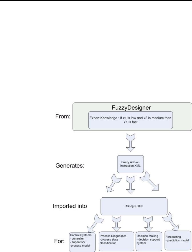
FuzzyDesigner is designed to work with Rockwell Automation’s Logix5000 family of controllers. A fuzzy system designed in FuzzyDesigner can be exported to an L5X Add-On instruction (AOI) format. You can then import the fuzzy AOI into any of your projects as needed. Fuzzy AOIs can be used by any of the programming languages (Function Block Diagram, Ladder Logic, or Structured Text). With FuzzyDesigner, you can also monitor and update the selected fuzzy AOI online, directly in the running controller. This is made available through the RSLinx OPC Server.
The Intended Use of FuzzyDesigner figure shows the underlying idea and intended use of the FuzzyDesigner software package used in designing Fuzzy Add-On Instructions for Logix applications. You can build smart components, based on the expert knowledge encoded in fuzzy If-Then rules. You can use these components in the many applications listed above.
Intended Use of FuzzyDesigner
Publication LOGIX-UM004A-EN-P — March 2007
![]()
|
Get Started with FuzzyDesigner |
11 |
A Fuzzy Add-On instruction does not typically compete against standard controls found in Proportional-Integral-Derivative Controllers (PID). Fuzzy logic is a complementary tool, and fills functional gaps not addressed in standard controllers such as PIDs or Model Predictive Controllers.
A development cycle of fuzzy logic solutions for Logix applications consists of multiple steps.
|
1. |
Design the fuzzy system in FuzzyDesigner. |
|
2. |
Generate the fuzzy Add-On Instruction. |
|
3. |
Integrate (import and instantiate) the fuzzy AOI to your RSLogix |
|
5000 project. |
|
|
4. |
Monitor and tune the fuzzy AOI running in Logix online by |
|
using FuzzyDesigner. |
|
|
Using FuzzyDesigner with RSLogix 5000 Software |
|
|
n |
p |
o
q
If you are unfamiliar with fuzzy logic, the next section introduces fuzzy logic terms and principles you might use in your fuzzy system.
Publication LOGIX-UM004A-EN-P — March 2007
12 Get Started with FuzzyDesigner
Fuzzy Logic and Fuzzy Control Essentials
This section introduces basic concepts used in a Fuzzy Add-On Instruction. The designer should know how to deal with an instruction’s inputs, outputs, and fuzzy If-Then rules that will be used to define input-output mapping.
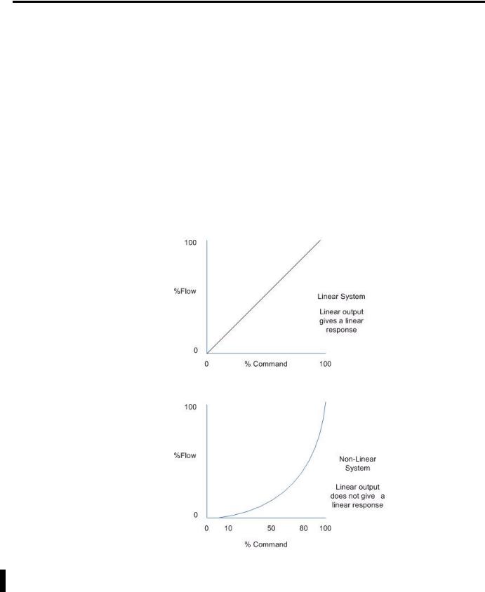
There are quite a number of systems or processes that are highly nonlinear, not well understood from the formal description point of view, or for which a mathematical model is not readily available. For these systems or processes, there is often an expert that is capable of supervising or controlling the process in a satisfactory manner. The figure Nonlinear System Example illustrates the difference between linear and nonlinear systems.
Nonlinear System Example
The decision making the expert uses in control system supervision can be expressed as a set of Fuzzy Logic If-Then rules.
Publication LOGIX-UM004A-EN-P — March 2007

|
Get Started with FuzzyDesigner |
13 |
An expert may be an operator, a maintenance person, or a control engineer, who knows what adjustments are needed during process instability. These adjustments may include defining setpoints for process variables, defining control action in feedforward or feedback contro,l or setting gains of conventional controllers, and may be as simple as turning a valve or knob.
Rockwell Automation is introducing a tool for building smart instructions that encode If-Then rules and use fuzzy logic internally to describe vague and incomplete knowledge in a natural way. Fuzzy Logic may serve in situations where:
•the process has not been automated and is running in Manual mode.
•a well-tuned PID controller does not provide the desired response, however, the expert knowledge is available to define the rules for a fuzzy algorithm.
Let’s look at an example where we will discuss building a Heat, Ventilation and Air Conditioning (HVAC) system that manipulates the compressor speed based on room temperature and humidity. In HVAC systems, room comfort is often associated with vague (fuzzy) values of temperature and humidity that are more suitable for describing the problem than numerical (crisp) values.
Fuzzy rules used in this example might be as follows.
|
If |
Then |
|
Temperature is high and humidity is |
Speed is medium |
|
high |
|
|
Temperature is medium and humidity |
Speed is high |
|
is very high |
|
Consider these factors when developing fuzzy rules:
•How do I specify High and other fuzzy values in fuzzy rules?
•How do the rules process numerical inputs provided by tags associated with sensors?
•How do the rules derive outputs from inputs?
•If the output generated is vague (fuzzy), how do I get the numerical (crisp) value at the output when needed?
Publication LOGIX-UM004A-EN-P — March 2007
14 Get Started with FuzzyDesigner
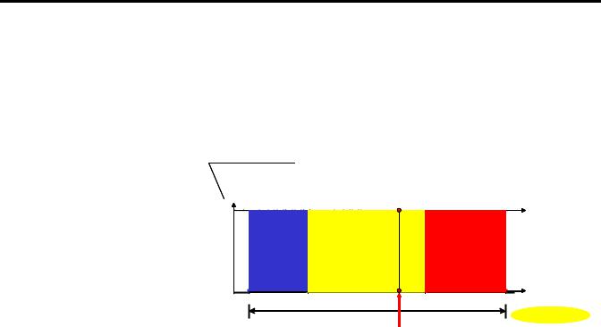
Crisp and Fuzzy
For temperature readings, you can classify a reading into three sets, Low, Medium and High. Each set contains values in a given interval, and the intervals do not overlap. This means that a single reading or value is uniquely classified into one set.
degree of membership (level of classification)
|
Classification |
|||
|
Low |
Medium |
High |
Result |
|
1 |
1.00 Medium |
||
|
0 |
0.0 High |
||
|
range |
0.0 Low |
||
|
temperature |
|||
|
20 |
150 |
||
|
Crisp Value |
|||
|
Degree of membership (DOM) is a value describing how well |
||
|
TIP |
||
|
the particular value of the variable (in this case, temperature) |
||
|
fits the meaning of the label of the set, Medium. If the DOM is |
||
|
1, the current temperature is understood as 100% Medium. |
However, vague classifications are more realistic as there is usually no sharp border between Low, Medium, or High temperatures. In this situation, however, a single numerical value might fall into multiple categories. For example, it might be partially Medium, and partially High as shown in the following figure. A specification of how much the particular value of temperature fits into the meaning of the label of the category (fuzzy set) is described by the membership function, which becomes a design parameter of the fuzzy controller.
Publication LOGIX-UM004A-EN-P — March 2007

|
Get Started with FuzzyDesigner |
15 |
Similar fuzzy terms are designed for the output variables, that is, Low,
Medium, and High for compressor speed in our example.
Fuzzy rules
The way in which the classified inputs are treated when passing through rules is shown in the following figure for our compressor control example.
Publication LOGIX-UM004A-EN-P — March 2007

16 Get Started with FuzzyDesigner
First, the numerical values of Temperature and Humidity get their meaning. In our case, the current setting of the Temperature is such that it is both 85% Medium and 40% High. Humidity is both 80% High and 50% Very High. The first rule is thus 80% true for the current inputs while the second rule is 40% true when using minimum for the and operation. The first rule states that, if 100% satisfied, the compressor should run at Medium speed. Currently, the first rule is only 80% fulfilled, so one method of how to consider that the rule is only 80% fulfilled is to truncate the Medium fuzzy set for the output at the level 0.8.
A similar situation happens with the second rule where High compressor speed is only 40% fulfilled. As both rules are used at the same time, their conclusions must be combined to get a fuzzy value for the output, which is compressor speed. The partially-fulfilled Medium and High fuzzy sets are unified, and a single fuzzy value is assigned to Compressor Speed. As conventional control systems cannot deal with fuzzy values, the fuzzy instruction includes conversion from a fuzzy to a crisp value. For this case, the center of gravity for the green area is computed and used to represent the original fuzzy value.
To summarize, the designer has to:
•define input and output variables.
•cover the interval of the respective variable by fuzzy sets (that is, membership functions).
•write if-then rules using labels of the fuzzy sets defined previously.
Potential Use of Fuzzy Logic
FuzzyDesigner enables you to enhance the functionality of existing or new control and decision making systems in various branches of industry.
The fuzzy system designed and generated by FuzzyDesigner can be used in control systems, for example, as a direct nonlinear fuzzy-rule based controller, PID-feedback control system supervisor, or a process model in a Model Predictive Control scheme. Input and output filters are used for signal preprocessing such as filtering, deriving trends, and many other functions that might add dynamics to the static I/O map generated from fuzzy rules. Input filters can also be designed in FuzzyDesigner. Output filtering is an option and contains, for instance, a discrete integrator fed by the output of the Fuzzy Add-On Instruction.
Publication LOGIX-UM004A-EN-P — March 2007

|
Get Started with FuzzyDesigner |
17 |
Nonlinear, Fuzzy Rule Based Supervisor of a PID Controller
|
Plant States |
|||
|
FUZZY |
feedforward |
||
|
FUZZY |
|||
|
SUPERVISOR |
|||
|
SUPERVISOR |
|||
|
PID |
|||
|
gains |
CV |
||
|
SP |
PID |
||
|
PLANT |
|||
|
PID |
|||
|
CONTROLLER |
PLANT |
||
|
CONTROLLER |
PV
The great advantage of fuzzy supervision is that it can be applied to existing control and there is little danger of making errors in design. Most frequently used is a supervised PID controller where PID gains, feedforward action, or setpoints are being modified dynamically by rules depending on the process status and external conditions defined through setpoints.
Smart Switching Between Conventional Controllers, Takagi-Sugeno Controller
|
FUZZY SUPERVISOR |
Plant State |
|
|
FUZZY SUPERVISOR |
||
Schedule weights [0,1]
|
CONTROLLER |
× |
|||
|
1 |
||||
|
CONTROLLER |
||||
|
1 |
+ CV |
|||
|
Setpoints |
CONTROLLER |
|||
|
PLANT |
||||
|
CONTROLLER |
× |
|||
|
2 |
+ |
PLANT |
||
|
2 |
+ |
|||
|
CONTROLLER |
||||
|
CONTROLLER |
× |
|||
|
3 |
||||
|
3 |
Process Variables
Another popular control structure with fuzzy logic is smart switching between local controllers. A local controller is an analytical controller designed to work around specific process operation conditions. Once the conditions change, the rule based supervisor decreases the influence of one controller and gives more weight to another controller that has been designed to work in the new conditions.
Publication LOGIX-UM004A-EN-P — March 2007
18 Get Started with FuzzyDesigner
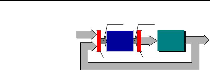
Feedback Control System with Direct Fuzzy Controller
|
Control system status |
Primary controls |
|
|
Setpoints |
||
|
FUZZY |
Control |
PLANT |
|
CONTROLLER |
Variables |
PLANT |
|
Input filter |
Output filter |
|
|
Process Variables |
A fuzzy controller with the above structure typically handles multiple inputs and generates multiple outputs. This system is recommended for experienced designers since control variables are direct functions of rules. The number of rules increases rapidly with the number of inputs and fuzzy terms for inputs. The problem of dimensionality can, however, be reduced by hierarchical structuring of the rule base of the controller, which is supported by FuzzyDesigner.
Specifications and Features
FuzzyDesigner features and specifications are summarized in the following tables.
For details, refer to the subsequent chapters.
Fuzzy System Components
Components are graphical objects, blocks you work with, to design a fuzzy system.
|
Component |
Membership |
AND |
OR |
Aggregation |
Inference |
Defuzzification |
|
functions |
(Activation) |
|||||
|
Type/method if applicable |
||||||
|
Input Port |
||||||
|
Input Linguistic |
Trapezoidal, |
|||||
|
Variable |
S-shape, and their |
|||||
|
inverses |
||||||
|
Rule Block |
Min/product |
Max |
||||
|
t-norms |
||||||
|
Output |
Trapezoidal, |
Max s-norm |
Mamdani/ Fuzzy |
CA/MCA/ |
||
|
Linguistic |
singleton |
Arithmetic |
MOM/SOM/ LOM |
|||
|
Variable |
||||||
|
Output Port |
||||||
Publication LOGIX-UM004A-EN-P — March 2007
|
Get Started with FuzzyDesigner |
19 |
|
Component |
Membership |
AND |
OR |
Aggregation |
Inference |
Defuzzification |
|
functions |
(Activation) |
|||||
|
Type/method if applicable |
||||||
|
Intermediate |
Max s-norm |
|||||
|
Linguistic |
||||||
|
Variable |
||||||
|
Output T-S |
Max s-norm |
|||||
|
Variable |
||||||
|
PID Controller |
||||||
Fuzzy System Analysis Tools
|
Tool |
Description |
|
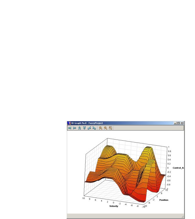
2D/3D mesh plots |
Visualization of input-output static mappings generated |
|
by the fuzzy system or its specified subsystem |
|
|
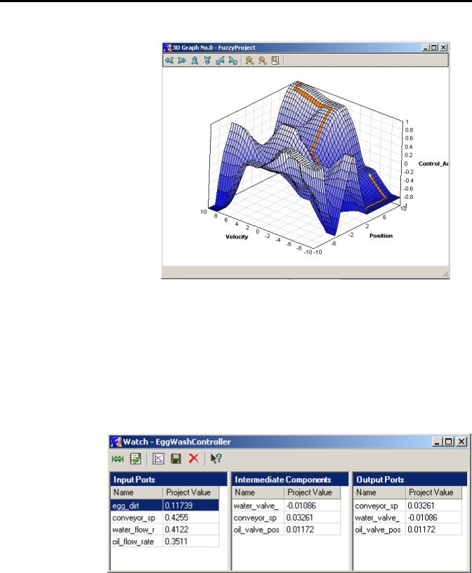
Interactive plot control |
Color, grid, texture, zoom, and viewpoint management |
|
Tracing fuzzy system evaluation |
Marks output on the mesh when input is being changed |
FuzzyDesigner Mesh Plot
Publication LOGIX-UM004A-EN-P — March 2007
20 Get Started with FuzzyDesigner
FuzzyDesigner Mesh Plot with Simulated Path
Fuzzy System Monitoring
|
Feature |
Description |
|
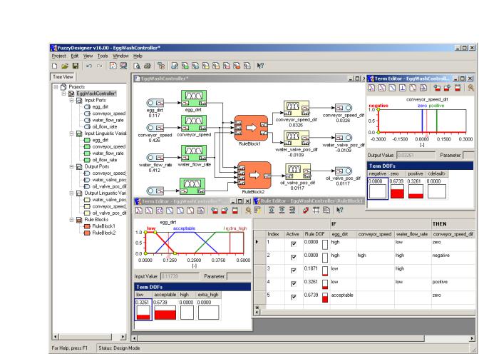
Numerical and graphical display |
Monitoring of all internal variables |
|
Archiving |
Recording specified internal or external variables |
|
History graph |
Plotting history graph for on-line or off-line monitoring |
Fuzzy System Monitoring Through Numerical Displays
Publication LOGIX-UM004A-EN-P — March 2007
![]()
|
Get Started with FuzzyDesigner |
21 |
Fuzzy System Monitoring Through Plotting Historical Recordings and On-Line
Update
FuzzyDesigner Project Formats
|
File Format |
Description |
|
XML |
.FSP – complete project file generated by |
|
FuzzyDesigner, .XML – user-supplied fuzzy system or |
|
|
project file |
|
Publication LOGIX-UM004A-EN-P — March 2007

22 Get Started with FuzzyDesigner
|
Direct Support of Logix5000 controllers |
||
|
FuzzyDesigner, version 16.00 and later, supports Rockwell |
||
|
Automation’s Logix5000 family of controllers. The fuzzy system |
||
|
designed using FuzzyDesigner can be exported to an RSLogix 5000 |
||
|
Add-On Instruction (AOI) XML import file. You can then import the |
||
|
fuzzy system into any of your projects as needed. Fuzzy AOI can be |
||
|
used by any of the programming languages (Function Block Diagram, |
||
|
Ladder Logic, or Structured Text). With FuzzyDesigner, you can also |
||
|
monitor and update the selected fuzzy AOI online, directly in the |
||
|
running controller. This is made available through RSLinx OPC Server. |
||
|
Features |
Description |
|
|
Export fuzzy AOI |
Utility for export of designed fuzzy system into L5X file. |
|
|
On-line parameter change |
Changing parameters of a fuzzy system downloaded to the controller |
|
|
dynamically is enabled. |
||
|
Real-time fuzzy system monitoring |
Exact copy of the fuzzy system running on the PLC allows FuzzyDesigner to |
|
|
monitor all internal variables on the computer when both copies are fed with |
||
|
the identical inputs. |
||
Integrated Design Environment (IDE) screen captures
Some of the FuzzyDesigner features, summarized in the preceding tables, are shown in this section.
Publication LOGIX-UM004A-EN-P — March 2007
|
Get Started with FuzzyDesigner |
23 |
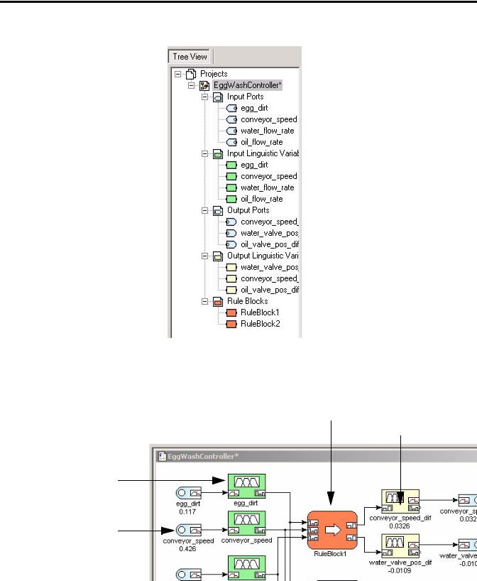
FuzzyDesigner Environment in Brief
Publication LOGIX-UM004A-EN-P — March 2007
24 Get Started with FuzzyDesigner
Project Tree view
FuzzyDesigner Environment — Component examples
|
Rule Block |
Output Liguistics |
|
Variable |
Input Linguistics
Variable
Input Port
Publication LOGIX-UM004A-EN-P — March 2007

|
Get Started with FuzzyDesigner |
25 |
FuzzyDesigner Membership Functions
Term Editor
Degree of Fulfillment window
FuzzyDesigner Rule Base — Rule Editor
Publication LOGIX-UM004A-EN-P — March 2007

26 Get Started with FuzzyDesigner
FuzzyDesigner Rule Interfacing
|
FuzzyDesigner Defuzzification Methods |
||||||||
|
DOF(negative) |
||||||||
|
DOF(negative) is maximal |
||||||||
|
DOF(zero) |
||||||||
|
y* |
y* |
|||||||
|
y* y* y* |
||||||||
|
(MCA) |
(CA) |
(SOM) (MOM) (LOM) |
Publication LOGIX-UM004A-EN-P — March 2007

|
Get Started with FuzzyDesigner |
27 |
FuzzyDesigner PID Controller
Publication LOGIX-UM004A-EN-P — March 2007

28 Get Started with FuzzyDesigner
Notes:
Publication LOGIX-UM004A-EN-P — March 2007
Chapter 2
FuzzyDesigner Component Library
Introduction
The FuzzyDesigner Component Library offers eight components from which you can efficiently build distributed fuzzy systems.
|
Topic |
Page |
Component Interface |
29 |
|
Library of Components |
30 |
|
Supported Membership Functions |
30 |
|
Input Port |
32 |
|
Input Linguistic Variable |
34 |
|
Output Linguistic Variable |
36 |
|
Output Takagi-Sugeno Variable |
42 |
|
Intermediate Linguistic Variable |
46 |
|
Rule Block |
47 |
|
PID Controller |
52 |
|
Output Port |
56 |
Component Interface
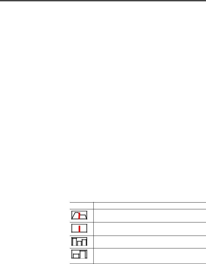
The connection between components is called a link. Generally, a Hierarchical Fuzzy System (HFS) computes with data in the form of a crisp (real) value and/or a fuzzy set. Not all components enable both types of data to be transferred over the link. The data type on both ends of a link should match. FuzzyDesigner uses icons to define a link type as follows.
FuzzyDesigner Icons
Icon Description
Crisp value (input or output value link) – input crisp values and crisp values resulting from defuzzification are transferred over the link
Crisp value (input or output value link) – crisp values are transferred over the link
DOF value (input or output logical link) – degrees of fulfillment of fuzzy terms of a fuzzy variable are transferred over the link to a rule block
DOF value (input or output logical link) – degrees of fulfillment of fuzzy terms resulting from rule block evaluation are transferred over the link to a fuzzy variable
Publication LOGIX-UM004A-EN-P — March 2007
30 FuzzyDesigner Component Library
Library of Components
The FuzzyDesigner Component Library offers the following components from which you can assemble fuzzy systems ranging from single input – single output systems to multiple input – multiple output systems with complex hierarchical structure of rules.
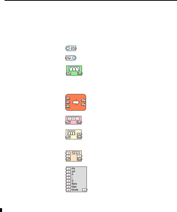
FuzzyDesinger Component Library Icons
|
Icon |
Name |
Description |
|
Input Port |
Preprocesses and stores values of a fuzzy |
|
|
system’s input variables. |
||
|
Output Port |
Stores values of a fuzzy system’s output |
|
|
variables. |
||
|
Input Linguistic |
Stores linguistic terms and is used for |
|
|
Variable |
classification of the actual component input, |
|
|
represented by a crisp value, into the fuzzy sets |
||
|
defined for the respective linguistic terms. In |
||
|
fuzzy control, the process where the input is |
||
|
converted from a crisp value is commonly called |
||
|
fuzzification. |
||
|
Rule Block |
Stores rules and computes degree of fulfillment |
|
|
of rule conditions . |
||
|
Intermediate |
Bridges logical chaining of rule blocks. |
|
|
Linguistic |
||
|
Variable |
||
|
Output Linguistic |
Stores linguistic terms and computes the output |
|
|
Variable |
value from degrees of fulfillment of stored terms |
|
|
(defuzzification). It implements the process of |
||
|
activation of output linguistic terms defined as |
||
|
fuzzy sets. |
||
|
Output |
Stores parameters of functional terms and |
|
|
Takagi-Sugeno |
computes the output value from degrees of |
|
|
Variable |
fulfillment of terms. |
|
|
PID Controller |
Allows intelligent supervision of a built-in PID |
|
|
controller. |
||
Supported Membership
Functions
Library blocks let you work with fuzzy sets as defined by membership functions. Let x be the linguistic variable and A(x) be the degree of membership of x to the fuzzy set A defined by the sketched membership function. FuzzyDesigner works with the following types of membership functions.
Publication LOGIX-UM004A-EN-P — March 2007
![]()
|
FuzzyDesigner Component Library |
31 |
|
Trapezoidal Membership Function with Parameters (vertices): (a,b,c,d) |
|||||||||
|
0 |
if |
x < a |
A(x) |
||||||
|
(x −a) /(b −a) |
if x [a,b) |
1 |
|||||||
|
1 |
if x [b,c] |
||||||||
|
A(x) = |
|||||||||
|
(x −d) /(c −d) |
if x (c, d] |
||||||||
|
0 |
if |
x > d |
0 |
||||||
|
a |
b |
c |
d |
x |
|||||
If a = b then A(a) = 1. If c = d then A(c) = 1.
Trapezoidal membership functions can be used in input and output linguistic variable components.
S-shape Membership Function (cubic spline) with Parameters: (a,b,c,d)
|
2 |
||
|
(a −b) |
||
|
3 |
||
|
A(x) = |
||
|
2 |
||
(d −c)3
|
0 |
if |
x < a |
|||||
|
2 |
3b −a |
||||||
|
(x −a) |
x − |
if x [a,b) |
|||||
|
2 |
|||||||
|
1 |
if |
x [b,c] |
|||||
|
2 |
3c −d |
||||||
|
(x −d) |
x − |
if x (c, d] |
|||||
|
2 |
|||||||
|
0 |
if |
x > d |
If a = b then A(a) = 1. If c = d then A(c) = 1.
S-shape membership functions can be used in input and output linguistic variable components.
Inverse Trapezoidal Membership Function with Parameters (vertices): (a,b,c,d)
|
1 |
if |
x ≤ a |
|
−b) /(a −b) if |
x (a,b] |
|
|
0 |
if |
x (b, c) |
|
−c) /(d −c) if |
x [c, d) |
|
|
1 |
if |
x ≥ d |
If a = b then A(a) = 1. If c = d then A(c) = 1.
Inverse trapezoidal membership functions can be used in an input linguistic variable component.
Publication LOGIX-UM004A-EN-P — March 2007

32 FuzzyDesigner Component Library
Input Port
Inverse S-shaped Membership Function (cubic spline) with Parameters: (a,b,c,d)
|
1 |
if |
x ≤ a |
A(x) |
||||||||||
|
2 |
3a −b |
1 |
|||||||||||
|
(x −b) |
2 |
if x (a,b] |
|||||||||||
|
(b −a) |
3 |
x − |
2 |
||||||||||
|
A(x) = |
0 |
if x (b, c) |
|||||||||||
|
2 |
(x −c) |
2 |
3d −c |
if x [c, d) |
|||||||||
|
(c −d ) |
3 |
x − |
2 |
||||||||||
|
0 |
|||||||||||||
|
1 |
if |
x ≥ d |
c |
x |
|||||||||
|
a |
b |
d |
|||||||||||
If a = b then A(a) = 1. If c = d then A(c) = 1.
Inverse S-shaped membership functions can be used in an input linguistic variable component.
Singleton Membership Function with Parameter (position, center) c
|
1 |
if x = c |
A(x) |
||||||
|
A(x) = |
otherwise |
|||||||
|
0 |
1 |
|||||||
|
0 |
x |
|||||||
|
c |
||||||||
Singleton membership functions can be used in an output linguistic variable component.
The fuzzy system Input Port component stores an actual input value entering the HFS. Optionally, you can preprocess the input values by using the linear digital filter. This filter is defined by its pulse-transfer operator H, expressed in terms of the backward-shift operator d, or equivalently in time-domain as a difference equation, as follows.
|
b(d ) |
b + b d +L + b |
m |
d m |
|||||
|
H (d ) = |
= |
0 |
1 |
, |
y(d ) = H (d )u (d ) |
|||
|
a(d ) |
1 |
+ a d +L + a |
||||||
|
n |
d n |
|||||||
|
1 |
y(t) = −a1 y(t −1) −L − an y(t − n) + b0u(t) + b1u (t −1) +Lbm u(t − m)
Filter numerator parameters : b0, b1, …bm ; filter denominator parameters : a1, …an
There are two ways for designing the filter:
•user defined filter.
•butterworth low pass filter .
Publication LOGIX-UM004A-EN-P — March 2007

|
FuzzyDesigner Component Library |
33 |
User Defined Filter
You set the numerator and denominator coefficients b0, b1, …bm and a1, …an directly (the parameters are entered in the specified order separated by the space character).
Butterworth Low Pass Filter
This filter can be created by specifying a normalized cutoff frequency q, taken from the interval [0.01, 1], and the order of the filter (1,2,3).
Bode Plot of the Butterworth Low-Pass Filter
0dB
|H(jω)|
ωc ω
This normalized frequency q corresponds to the absolute frequency ωc = qωn , where ωn = π / Ts is the Nyquist frequency for the sampling period Ts.
WARNING
All dynamical terms in a fuzzy system (filters, PID controllers) have to share the common sampling period Ts; otherwise the system will not work correctly.
Connections
The output link of the input port is connectable to all components expecting a crisp value at the input. This includes the following components:
•Input Linguistic Variable
•Output Port
•Output Takagi-Sugeno Variable (accepts crisp values only)
•PID (accepts crisp values only)
Publication LOGIX-UM004A-EN-P — March 2007

34 FuzzyDesigner Component Library
Input Linguistic Variable
trapezoid
Parameters
•Name of the component
•Vector b = [b0, b1,,bm] , coefficients of the filter transfer function numerator b(d)– optional
•vector a = [a1, …,an], coefficients of the filter transfer function denominator a(d) – optional
The fuzzy system Input Linguistic Variable component stores membership functions (fuzzy sets) of terms and is used for fuzzification (classification) of the component input – a crisp value. The component output is a vector of degrees of fulfillment of all terms for the crisp input or degree of overlapping for the input fuzzy set.
An Input Linguistic Variable component consists of linguistic terms. Each linguistic term is defined by a fuzzy set, that is by the membership function and the name. There are four supported membership functions.
•Trapezoidal membership function
•S-shaped membership function
•Inverse trapezoidal membership function
•Inverse S-shaped membership function
|
inverse trapezoid |
s-shape |
inverse s-shape |
Linguistic terms are defined on specified range [xmin, xmax] (universe of discourse).
The component crisp input is fuzzified. The result of fuzzification of
the crisp input value x* is a degree of fulfillment (DOF) of the terms, which is computed for each term given by the membership function A(x) as follows.
|
A(x* ) |
if x* [xmin , xmax ] |
|||
|
if x* < xmin |
||||
|
DOF(A) = A(xmin ) |
||||
|
if x |
* |
> xmax |
||
|
A(xmax ) |
Publication LOGIX-UM004A-EN-P — March 2007

|
FuzzyDesigner Component Library |
35 |
This value is simply membership degree of value x* to fuzzy set A and can be interpreted as a degree to which the proposition (x* IS A) is
true. An example of fuzzification of the crisp input value x* is shown in the figure Process of Crisp Input Fuzzification. The component input value is -0.3191.
The component consists of three linguistic terms – negative, zero, and positive. The output of the component is the vector [0.6383, 0.3617, 0]
– where 0.6383 is a degree of fulfillment of the term negative, 0.3617 is a degree of fulfillment of the term zero, and 0 is a degree of fulfillment of the term positive.
This value is simply membership degree of value x* to fuzzy set A and
can be interpreted as a degree to which the proposition (x* IS A) is true.
Process of Crisp Input Fuzzification
 Current input value
Term DOF = membership degree
DOFs of all terms are provided to connect rule blocks to complete the fuzzy logic inference.
Publication LOGIX-UM004A-EN-P — March 2007

36 FuzzyDesigner Component Library
Connections
The input link of the input linguistic variable is connectable to any of these components providing a crisp value:
•input Port component.
•output Linguistic Variable component.
•output Takagi-Sugeno Variable component.
•PID component.
The output logical link of the input linguistic variable is connectable to components expecting a DOF value (as a result of fuzzification or defuzzification), such as the Rule Block component.
Parameters
Output Linguistic Variable
•Name of the component
•Range of the input value of the component [xmin, xmax]
•List of terms described by
–Name
–Type of membership function
–Vector of membership function parameters [a, b, c, d]
The fuzzy system Output Linguistic Variable component stores output linguistic terms and is used for defuzzification. The component has a logical input link, degrees of fulfillment of all linguistic terms of the respective linguistic variable. The link can be multiple, meaning that the component can be connected to several rule blocks. The component has two output links – value and logical links. Depending on the selected inference algorithm and defuzzification method, the
component computes a crisp value y*. Such a result provides an output value link. The output logical link enables the connection of the component directly to another rule block. If the component input link is connected to a single rule block, the output degrees of fulfillment are the same as the input degrees of fulfillment. If the component is connected to several rule blocks, the output degrees of fulfillment of linguistic terms are computed as a maximum of the corresponding input degrees of fulfillment.
Publication LOGIX-UM004A-EN-P — March 2007

|
FuzzyDesigner Component Library |
37 |
The Output Linguistic Variable component stores linguistic terms. Each linguistic term is defined by its fuzzy set, that is, the membership function and the name. The following membership functions are supported:
•Trapezoidal membership function
•Singleton membership function
Linguistic terms are defined on the specified range [ymin, ymax] (universe of discourse).
Defuzzification
Defuzzification converts fuzzy sets to a crisp value, taking into account their degrees of fulfillment.
FuzzyDesigner supports the following defuzzification methods –
Centroid Average, Maximum Center Average, Mean of Maximum,
Smallest of Maximum, and Largest of Maximum.
|
y – output variable |
|||||||||||||||||||
|
Y – universe of output variable, defined by an |
A(y) |
… |
… |
||||||||||||||||
|
interval |
|||||||||||||||||||
|
y* – crisp output value (after defuzzification) |
|||||||||||||||||||
|
Ai –membership function the output term i, |
cj y* |
cj+1 |
y |
||||||||||||||||
|
that is, its fuzzy set |
A – fuzzy set, which is being defuzzified, obtained as a union of all “clipped” output membership functions.
A(y) – membership degree of variable y in fuzzy set A
Publication LOGIX-UM004A-EN-P — March 2007

38 FuzzyDesigner Component Library
Centroid Average – CA generally
An output value computed by this method is equal to the weighted average of the positions of the centroids of the output membership functions Aj weighted by their actual activation levels. The output value is computed as follows.
M
∑A(cj ) cj
y* = j=1M
∑A(cj )
j=1
where:
•A(cj) is the maximum of the degrees of fulfillment over all the rules with the consequent Aj
•cj is a position of the centroid of the membership function Aj which is calculated in advance
•M is a number of fuzzy sets Aj
This method is used for applications when output is to be a continuous function of inputs for example, a control system
Maximum Center Average – MCA generally
This method is similar to the Centroid Average method except that ci , the center of maxima of Bi , is calculated in advance. This method is also continuous and allows the output value to reach the limits of the range.
Defuzzification CA=MCA for singletons.
negative*DOF(negative) + zero*DOF(zero) + positive*DOF(positive)
Output =
DOF(negative) + DOF(zero) + DOF(positive)
Output = Default Value, if all term DOFs = 0
DOF(positive)
Publication LOGIX-UM004A-EN-P — March 2007

|
FuzzyDesigner Component Library |
39 |
Defuzzification CA and MCA for trapezoids.
Trapezoids are automatically transformed to singletons.
CA = centroid method
MCA = mean of maxima (to allow reaching limit values of the range)
The output value is then computed in the same way as for singletons.
Mean of Maxima – MOM generally
This method computes the mean value of the interval at which the output fuzzy set reached the largest membership degree. It is defined as follows.
|
y* = mean c |
A (c ) = max |
( |
A |
(c |
) |
) |
||||||||||||||
|
i |
i i |
j |
j |
|||||||||||||||||
|
{ |
j |
} |
A(y) |
… |
… |
|||||||||||||||
|
y* |
y |
|||||||||||||||||||
Smallest of Maxima – SOM generally
This method is similar to the previous one. Instead of mean value, the minimum value of the interval is chosen. The defuzzified output is computed as follows.
|
y* =smallest c |
A (c ) = max |
( |
A |
(c |
) |
) |
||||||||||||
|
i |
i i |
j |
j |
|||||||||||||||
|
{ |
j |
} |
A(y) |
… |
… |
|||||||||||||
|
y* |
y |
|||||||||||||||||
Publication LOGIX-UM004A-EN-P — March 2007

40 FuzzyDesigner Component Library
Largest of Maxima – LOM generally
The only difference to the previous method is that the maximum value of the interval is chosen. The defuzzified output is defined as follows.
|
y* = largest c |
A (c ) = max |
( |
A |
(c |
) |
) |
||||||||||||||||||||||||
|
i |
i i |
j |
j |
|||||||||||||||||||||||||||
|
{ |
j |
} |
A(y) |
… |
… |
|||||||||||||||||||||||||
|
y |
* |
y |
||||||||||||||||||||||||||||
Mean of Maxima, Smallest of Maxima, and Largest of Maxima methods are not continuous and are mainly used in applications on decision-making and classification when the task is to choose from several alternatives.
If no term is activated (DOF = 0) then the inference result is set to a user defined crisp default value.
Defuzzification SOM, MOM, LOM for singletons
Output value is computed as a reference singleton with maximal term
DOF.
If more terms have the same maximal DOF>0, then:
•SOM: output = smallest of the singletons with maximal DOF.
•LOM: output = largest of the singletons with maximal DOF.
•MOM: output = mean of the singletons with maximal DOF.
Publication LOGIX-UM004A-EN-P — March 2007
![]()
|
FuzzyDesigner Component Library |
41 |
Output = term with maximal DOF = zero
Output = Default Value, if all DOFs = 0
DOF(zero) is maximal
Defuzzification SOM, MOM, LOM for trapezoids
Trapezoids are automatically transformed to singletons.
SOM MOM LOM
The output value is then computed in the same way as for singletons.
Recommendation
•Use singletons to have easier insight to the output inference mechanism
•No functionality is lost
Publication LOGIX-UM004A-EN-P — March 2007

42 FuzzyDesigner Component Library
Connections
The input link of the output linguistic variable can be connected to a component providing the DOF value (as a result of fuzzy inference), that is, the Rule Block component.
The output value link of the output linguistic variable can be connected to components expecting a crisp value, such as:
•Output Port component.
•Input Linguistic Variable component.
•Output Takagi-Sugeno Variable component (only crisp values are considered).
•PID component (only crisp values are considered).
The output logical link of the output linguistic variable can be connected to components expecting the DOF value (as a result of fuzzification or defuzzification), that is, the Rule Block component.
Parameters
•Name of the component
•Range of the output value of the component [ymin, ymax]
•List of terms described by
–The name
–The type of membership function
–The vector of membership function parameters [a, b, c, d] for the trapezoidal membership function, [c] for the singleton membership function
•Type of fuzzy inference
•Type of defuzzification method
•Default output value
Output Takagi-Sugeno Variable The classical model by Takagi-Sugeno offers a fuzzy rule based, smooth switching between analytical functions. The consequent is a
crisp function of the antecedent variables rather than a fuzzy proposition. A general form of a Takagi-Sugeno model is:
Ri: IF x is Ai THEN yi = fi(x)
Publication LOGIX-UM004A-EN-P — March 2007

|
FuzzyDesigner Component Library |
43 |
The consequent functions fi are typically chosen as instances of a suitable parameterized function, whose structure remains equal in all the rules and only the parameters vary. Most often, these functions are linear combinations of antecedent variables. In control engineering, each rule usually represents local dynamics in different state space regions and the consequent is given in the form of a state-space or an ARX model. The overall model of the system is achieved by fuzzy blending of these linear models.
FuzzyDesigner supports Takagi-Sugeno fuzzy systems with linear functions in the rule consequents written in the following form.
Ri : IF x1 is Ai1 andLand xn is Ain THEN y = ai0 +ai1 x1 +K+ain xn
or
Ri : IF x1 is Ai1 andLand xn is Ain THEN y = ai0
The Takagi-Sugeno fuzzy system with the constant value in the rule consequents can be also considered as a fuzzy system with singleton membership functions in the rule consequents. If the Centroid Average or Maximum Centroid Average defuzzification and Fuzzy Arithmetic Inference method is chosen, than the behavior of both fuzzy systems is the same.
The fuzzy system Output Takagi-Sugeno Variable component stores parameters of reference linear or constant consequent functions. The component has two input links – a logical input link (degrees of fulfillment of all reference functions) that can be multiple, meaning that the component can be connected to several rule blocks, and a value input link (connectable to components that produce crisp values), which can be multiple too. The number of links depends on the number of consequent variables.
The component has two output links:
•Value link
•Logical link
The output logical link enables the connection of the component directly to other rule blocks. If the component input link is connected to one rule block, the output degrees of fulfillment are the same as the input degrees of fulfillment. If the component is connected to several rule blocks, the output degrees of fulfillment of reference membership functions are computed as a maximum of the corresponding input degrees of fulfillment.
Publication LOGIX-UM004A-EN-P — March 2007

44 FuzzyDesigner Component Library
The output Takagi-Sugeno Variable component consists of functional terms. Each functional term is defined by its parameters (a0, a1, … an) and its name (the parameters are entered in the specified order separated by the space character). The type of every linguistic term can be different. There are two supported functions.
•Linear function: f(x1,x2,…xn) = a0 + a1 x1 + a2 x2 +…+ an xn
•Constant function: f(x1,x2,…xn) = a0
Where x1,x2,…xn are outputs from preceding components providing crisp values.
The component calculates an inference result as a crisp value y*
∑dofi fi (x1 , x2 ,L, xn )
y* = i
∑dofi
i
where dofi is DOF of i-th term. This value is finally limited to the range
[ymin, ymax]. If no term is activated (DOF = 0) the inference result is a user-defined crisp default value.
Publication LOGIX-UM004A-EN-P — March 2007

|
FuzzyDesigner Component Library |
45 |
|
EXAMPLE |
Different linear-state feedback controllers are to be smoothly activated for different process states and |
|
|
setpoints – scheduling controller gains. There are three rules. |
||
|
• IF (x1 IS A1 ) AND (x2 |
IS B1) |
THEN y = K0 |
+ K1*x1 + K2*x2 (= y1) |
|
• IF (x1 IS A2 ) AND (x2 |
IS B2) |
THEN y = G0 + G1*x1 + G2*x2 (= y2) |
|
|
• IF (x1 IS A3 ) AND (x2 |
IS B3) |
THEN y = C0 |
(= y3) |
Defined (functional) terms:
K, type LINEAR, parameters = K0 K1 K2
G, type LINEAR, parameters = G0 G1 G2
C, type CONSTANT, parameters = C0
Evaluation (weighted average of functions):
|
x1 |
y |
|
|
from a rule blockx2 |
||
|
to a rule block |
||
y =
y1*DOF(K) + y2*DOF(G) + y3*DOF(C)
DOF(K) + DOF(G) + DOF(C)
y = Default Value, if all DOFs = 0
Connections
The input logical link of the output Takagi-Sugeno variable can be connected to a component providing a DOF value (as result of fuzzy inference), that is, the Rule Block component.
Publication LOGIX-UM004A-EN-P — March 2007

46 FuzzyDesigner Component Library
Intermediate Linguistic
Variable
The input value link of the output Takagi-Sugeno variable can be connected to components providing a crisp value, such as:
•Input Port component.
•Output Linguistic Variable component.
•PID component.
•Output Takagi-Sugeno Variable component.
The output value link of the output Takagi-Sugeno variable can be connected to components expecting a crisp value, such as:
•Output Port component.
•Input Linguistic Variable component.
•Output Takagi-Sugeno Variable component (only crisp values are considered).
•PID component (only crisp values are considered).
The output logical link of the output Takagi-Sugeno variable can be connected to components expecting a DOF value (as result of fuzzification or defuzzification), such as the Rule Block component.
Parameters
•Name of the component
•Range of the input value of the component [ymin, ymax]
•List of functional terms described by
–The name
–The type of the function
–The vector of the function parameters [a0, a1, … , an] for the linear function, [a0] for the constant function
•Default value
The fuzzy system Intermediate Linguistic Variable component is used as a buffer allowing logical chaining of rule blocks.
The component consists of linguistic terms with symbolic meaning. Each linguistic term is defined by its name. Degrees of fulfillment of all terms are results of previous logic inference in preceding rule blocks connected to this component.
Publication LOGIX-UM004A-EN-P — March 2007

|
FuzzyDesigner Component Library |
47 |
If the component input link is connected to a single rule block, the output degrees of fulfillment just copy inputs. If the component input is connected to several rule blocks, the output degrees of fulfillment of stored linguistic terms are computed as a maximum of the corresponding input degrees of fulfillment.
Connections
The input logical link of the Intermediate Linguistic Variable can be connected to a component providing a DOF value (as result of fuzzy inference in a rule block), that is, the Rule Block component.
The output logical link of the Intermediate Linguistic Variable can be connected to components expecting a DOF value (as result of fuzzification or fuzzy inference in a rule block), such as the Rule Block component.
Parameters
Rule Block
•Name of the component
•List of terms defined by their names
The fuzzy system Rule Block component stores rules, performs fuzzy logic inference based on fuzzy rules and computes degrees of fulfillment of linguistic terms for consequent variables (output logical links) from degrees of fulfillment of linguistic terms used in the rule for premise variables (input logical links).
Publication LOGIX-UM004A-EN-P — March 2007
 Loading…
Everybody enjoys nifty little tips and tricks to get their work done faster. This listing is for Allen Bradley’s RSLogix 5000 software. Feel free to add your own tips and tricks using the ‘add comment’ link.
General
- To access Release Notes for this version of software, choose Release Notes from the Help menu.
- The Quick View Pane, located below the Controller Organizer, provides «thumbnail» information for the selected component.
- The Watch Pane, located below the language editor window, provides monitoring for all tags referenced in the active routine window.
- The Controller Organizer is dockable. That is, you can drag it to the left or right side of the screen, or float it somewhere in between.
- Hide/show the Controller Organizer via a toolbar button to make more display area for editors.
- RSLogix 5000 supports Cut/Copy/Paste/Drag/Drop of components within the Controller Organizer as well as to other instances of RSLogix 5000.
- Double-clicking on error messages displayed in the Error Window will navigate you to where the error was encountered.F4 and Shift-F4 can be used to move between errors.
- You can reorder the columns in the tag editor by clicking on the title and dragging it to a new position.
- To simultaneously display logic in multiple routines, select Window -> New Window and then arrange the windows manually. Or select Window -> Tile Horizontal.
- To remove a yellow triangle warning symbol on a device, first check the connection status. If the status is «Connection is not scheduled», re-open the RSNetWorx software. Return to RSLogix 5000 software and the yellow triangle should be gone.
- On one computer, you can install and simultaneously launch (run) multiple translated versions of RSLogix 5000 software.
- Once you do a partial import of rungs, add-on instructions, or user-defined data types, you can’t undo the import. If the import didn’t work as expected, close the project without saving.
- When you select a partial import, make sure to select the correct rung or trend file. Both files have L5X extensions and the software doesn’t prevent you from selecting the wrong file. If you try to import a rung where a trend is expected, or vice versa, the software does display an error that the import failed.
- Partial import of rungs works in all ladder routines, including Add-On Instructions.
- In version 15, the Tag Editor added support for New Window.
- To simultaneously display logic in multiple routines, select Window -> New Window and then arrange the windows manually. Or select Window -> Tile Horizontal.
Keyboard
- Keyboard shortcuts are listed in the Online Help, under the «Navigating the Software» topic.
- You can use Ctrl+Page Down and Ctrl+Page Up to move between tabs in a dialog or routine window.
- You can use Ctrl+Tab and Shift+Ctrl+Tab to move between multiple RSLogix 5000 views.
- You can use Ctrl+G to invoke the Go To dialog. The Go To dialog is convenient for navigating the software.
- You can use Alt+Insert to open the Language Element browser in any of the language editors. You can also invoke this browser by pressing the Insert key in the LD, SFC and FBD editors.
- You can use Ctrl+Space to invoke the Tag browser from within the ST editor.
- You can use the Go To dialog (Ctrl+G) to quickly navigate to routines called by the current routine and to routines that call the current routine.
- In the Sequential Function Chart Editor, you can use the Routine Overview (Ctrl+B) tool to view your entire SFC and help navigate to a specific area of your chart.
- Double-clicking on error messages displayed in the Error Window will navigate you to where the error was encountered. F4 and Shift-F4 can be used to move between errors.
- The Language Element browser is a shortcut to adding logic. In the any of the language editors: use Alt+Insert, type the instruction mnemonic, and press Enter. You can also invoke this browser by pressing the Insert key in the LD, SFC and FBD editors. This short cut can be much quicker than using the instruction toolbar.
- As you use the keyboard to move the cursor around grid cells, press Alt+Down arrow to activate any controls that are active for that cell. This works in all grid-based editors, such as the Tag Editor, Data Monitor, etc. This gives you a way to access cell controls via the keyboard, rather than using the mouse.
Controller Projects
- Whenever you go online using RSLogix 5000, changes made to controller are simultaneously made to a temporary copy of the project file (.ACD). Save makes these changes permanent. Therefore, an upload is only necessary to obtain the latest copy of the tag data in the controller.
- Both Rockwell Automation and third-party sample projects are installed with RSLogix 5000. You can find them in the RSLogix 5000 Samples folder. These projects demonstrate program techniques and code that you can use to program select modules.
- Avoid pointing one alias tag to another alias tag to ensure the application maintains the appropriate references after an upload.
- Avoid pointing multiple alias tags to the same base tag to ensure the application maintains the appropriate references after an upload.
- All tag names are downloaded and resident in the controller along with your logic.
- On download, if the ControlNet schedule stored in the offline RSLogix 5000 project file is old, RSLogix 5000 will retrieve the latest ControlNet schedule from the associated RSNetWorx project file. To make an association to an RSNetWorx project file, use the RSNetWorx tab in the Module Properties dialog of the ControlNet scanner.
- RSLogix 5000 supports moving your project from one Logix platform/controller to another.
- ACD, L5K, CSV, and L5X files are independent of which translated version of RSLogix 5000 imports or exports the file. The software doesn’t create language-specific import/export files.
- Use any translated version of RSLogix 5000 software to go online to a controller without having to re-download.
- In a safety controller, standard tags in a safety mapped relationship follow safety restricted states. For example, a standard tag mapped to a safety tag is read-only in a safety locked state.
- Use Add-On Instructions to initialize tag values to specific values at the beginning of each routine or program scan. Then source protect the AOI to assure that values are correctly initialized and not overwritten manually.
- The order of members within a User-Defined Data Type affect the memory size of the data type. Within the UDT, keep members of the same data type together.
I/O Configuration
- Module icons in the I/O Configuration folder change to indicate the module has faulted or the connection to the module has been interrupted.
- To remove a yellow triangle warning symbol, first check the connection status. If the status is «Connection is not scheduled», re-open the RSNetWorx software. Return to RSLogix 5000 software and the yellow triangle should be gone.
- To easily find a module in the Select Module Type dialog, simply start typing any part of the module name or description. When you start typing, the Find Module dialog is launched automatically.
- Use rack optimized communication formats for digital I/O modules to minimize amount of controller memory and communications overhead associated with these modules.
- RSLogix 5000 automatically creates controller tags when you create an input or output module. You can reference these tags directly in your logic.
- Use alias tags to assign names to specific input/output data and/or to provide a short alternative to lengthy structure member names.
- When you configure an analog I/O module, hold the shift key as you move the slider to increment HH, H, L, and LL values in whole numbers.
- Copy I/O data to a User-Defined Type (UDT) so you can synchronize I/O data with program scan. The UDT also enables easier mapping of physical I/O.
Tasks, Programs and Equipment Phases
- An event task in Logix is similar to the processor input interrupt (PII) in the PLC-5. Multiple event tasks can exist in the controller, each configured to execute at the initiation of independent triggers.
- A periodic task in Logix is similar to the selectable timed interrupt (STI) in the PLC-5. Multiple periodic tasks can exist in the controller, each configured to execute at independent rates.
- Double-click on a state in an Equipment Phase to navigate to the logic for that state.
- Use RSBizWare Batch software to create Equipment Phases. Use the Equipment Editor to create the phases, define parameters, and synchronize the phases with an RSLogix 5000 project.
- Use any programming language (Ladder, Structured Text, FBD, or SFC) to program state routines in Equipment Phases.
- The fault routine for an Equipment Phase is the same as the fault routine for a program. Use a fault routine to allow logic to run before the controller faults due to a programming error.
- The Prestate routine runs all the time, even when the Equipment Phase is not active.
- The Prestate routine for an Equipment Phase is optional. Use the Prestate routine to execute the error detection logic for your phases.
- You don’t have to implement all the available states in an Equipment Phase. On the Equipment Phases properties, check the «Complete State if not implemented» option.
- In the Phase Monitor, the states you can write code have action names and have a command word leading into the state, such as Start leads to the Running state. You add routines to these states. Waiting states don’t require routines. The phase waits for a command to move to the next state. For example, Idle and Hold.
Tags, Data Types and Other Data
- As you organize, add, or delete members of a User-Defined Data Type, the software adjusts the associated tag members and values accordingly so that remaining members retain their values.
- In the tag browser, click the >> button to display the tag filter. Use the tag filter to display unused tags or tags of a particular data type.
- The tag browser filters tags in some situations. If you don’t see a tag you expect, change the tag filter.
- In version 15, the Tag Editor added support for New Window.
- You can use arrays to do indirect addressing. RSLogix 5000 supports arrays of one, two, and three dimensions.
- You can create a recipe by creating a new data type and then creating a tag which uses that data type. Your new data type can contain descriptive field names.
- RSLinx uses memory in a Logix controller to read data values. Use the following equation to estimate the memory needed: (1.5Kbyte + (Number of individual tags * 45 bytes) + (Number of array or structure tags * 7))
- The Watch Pane, located below the language editor window, provides monitoring for all tags referenced in the active routine window.
- You can trend a tag by right-clicking the tag and choosing «Trend Tag «.
- You can find all occurrences of a tag by right-clicking the tag in logic and choosing «Find All «.
- Logix controllers are optimized for the DINT and REAL data types. Use these data types to avoid conversion overhead and optimize performance.
- You can optimize the communication performance of acquiring data from Logix controllers by consolidating multiple data values into a User-Defined Data Type (UDT) or array.
- Indexed references to array elements add additional scan time overhead to the application. Use single dimension arrays whenever possible.
- When building a User-Defined Type (UDT), locate all bits or BOOLs adjacent to each other to minimize the amount of controller memory required to store the data.
- RSLogix 5000 automatically creates controller tags when you create an input or output module. You can reference these tags directly in your logic.
- Use alias tags to assign names to specific input/output data and/or to provide a short alternative to lengthy structure member names.
- Avoid pointing one alias tag to another alias tag to ensure the application maintains the appropriate references after an upload.
- Avoid pointing multiple alias tags to the same base tag to ensure the application maintains the appropriate references after an upload.
- Controller tags apply to the entire controller and can be referenced by any program. Program tags apply only to individual programs. This means program tags can have the same names in more than one program, allowing programs to be copied and reused.
- You can reorder the columns in the tag editor by clicking on the title and dragging it to a new position.
- All tag names are downloaded and resident in the controller along with your logic.
- You can export (and import) tag definitions to a comma separated value (CSV) file and manipulate them using external tool, e.g. spreadsheet, text editor.
- For tables of bits (BOOL), use a DINT array to ensure full access via the file and diagnostic instructions COP, DDT, FBC, etc.
- In a safety controller, standard tags in a safety mapped relationship follow safety restricted states. For example, a standard tag mapped to a safety tag is read-only in a safety locked state.
- The order of members within a User-Defined Type affect the memory size of the data type. Within the UDT, keep members of the same data type together.
Routines
- Logix supports four controller programming languages: Ladder, Function Block Diagram, Structured Text, and Sequential Function Chart.
- To simultaneously display logic in multiple routines, select Window -> New Window and then arrange the windows manually. Or select Window -> Tile Horizontal.
- Multiply the number of words in a PLC/SLC program times 18 to estimate the amount memory (in bytes) needed in a Logix controller.
- To display context-specific instruction help, select an instruction or element and press F1.
- The Language Element browser is a shortcut to adding logic. In the any of the language editors: use Alt+Insert, type the instruction mnemonic, and press Enter. You can also invoke this browser by pressing the Insert key in the LD, SFC and FBD editors. This short cut can be much quicker than using the instruction toolbar.
- You can find all occurrences of a tag by right-clicking the tag in logic and choosing «Find All «.
- You can use the Go To dialog (Ctrl+G) to quickly navigate to routines called by the current routine and to routines that call the current routine.
- You can drag and drop from the instruction toolbar in any of the language editors. In SFC editor, the elements auto-connect.
- Use the CPS instruction to provide buffering of communications and I/O data to minimize impact of asynchronous data arrival.
- For tables of bits (BOOL), use a DINT array to ensure full access via the file and diagnostic instructions COP, DDT, FBC, etc.
- Controller tags apply to the entire controller and can be referenced by any program. Program tags apply only to individual programs. This means program tags can have the same names in more than one program, allowing programs to be copied and reused.
- In the Sequential Function Chart Editor, you can use the Routine Overview (Ctrl+B) tool to view your entire SFC and help navigate to a specific area of your chart.
- Logix controllers perform a prescan of logic on startup to perform initialization. A tag used as an index can cause a startup fault if its value is larger than the array length. Use a Fault routine to detect and reset this condition.
- In the Sequential Function Chart Editor, you can use the indicator tag field in an action to specify a tag value to monitor during execution.
- In the Sequential Function Chart Editor, you can select multiple SFC elements and use the Layout SFC Elements feature to automatically rearrange the selected elements as needed to provide adequate spacing, avoid page boundaries, and left or center justify branches.
- In the Sequential Function Chart Editor, you can change the order in which selection branch legs are evaluated from the Set Sequence Priorities dialog.
- Refer to the Online Help for the Action Properties dialog — General Tab Overview for a useful timing diagram that explains how the various action qualifiers affect the execution of an action.
- You can customize the auto-naming of Sequential Function Chart Steps, Actions, Transitions, and Stop elements from the Workstation Options and Routine Properties dialogs.
- You can attach text boxes to language elements in FBD and SFC logic to maintain their relative positions if you move logic.
- You can use Ctrl+Space to invoke the Tag browser from within the ST editor.
- Comments in Structured Text are downloaded to the controller. This includes comments in Structured Text routines and embedded Structured Text in SFC routines.
- In the Structured Text Editor, you see the words colored to indicate keywords, tag names, and other recognized words. You can change the colors used by the editor by choosing Options from the Options menu.
- In the Structured Text Editor, you can configure the instruction’s parameters by right-clicking an instruction name and choosing «Instruction Properties».
- You can use instructions available in Ladder and Function Block Diagram routines also in Structured Text routines.
- You can configure the sheet size for your Function Block Diagram or Sequential Function Chart routines from the Routine Properties dialog.
- In the Function Block Editor, you can configure the block’s parameters by clicking the Browse (…) button on the upper right side of the block.
- RSLogix 5000 supports pending edits on multiple rungs when online editing ladder logic.
- When editing ladder routines, you can create logic using ASCII (for example: «XIC MYTAG») by either typing when a rung is selected, pressing the Enter key when a rung is selected, or double clicking to the left of a rung.
- In the Ladder Diagram Editor, you can insert a branch level above the current level by right clicking the left side of the branch and select Add branch. To insert a branch level below the current level, right click the right side of the branch and select Append New Level.
- Partial import of rungs works in all ladder routines, including Add-On Instructions.
- When performing a partial import of rungs, change tag names to create new tags in the imported logic.
- Once you do a partial import of rungs, add-on instructions, or user-defined data types, you can’t undo the import. If the import didn’t work as expected, close the project without saving.
- On a partial import of rungs, the exported data values are also imported. This includes configured message instructions. Partial imports/exports can save time versus copying and pasting since copying and pasting does not copy data values.
- Copy pieces of logic into other applications like Microsoft Word in a bitmap or metafile format.
- If you want a subroutine to execute every scan, copy the first instruction and paste it right next to the original instruction. Use the same tags on the duplicate instruction as on the first instruction. Then insert an AFI instruction before the duplicate.
- To copy a group of rungs to paste into another routine later, select the rungs and drag them to the desktop. This copies the rungs into a file that you can later drag into another routine.
- You can drag components from the Controller Organizer into the Ladder Editor instruction.
- Double click or press Enter at the end of a ladder rung to create and start a textual edit of that rung.
- To drag a language element from one routine to another, drag the element over the routine tabs at the bottom of the editor to switch the routine.
Add-On Instructions
- To display the logic of an Add-On Instruction, select the instruction and use the context menu (right click) to open the logic.
- You can drag an Add-On Instruction from the Controller Organizer into any language editor.
- Copy an Add-On Instruction Definition from one project and paste into another to move that AOI and referenced AOIs in to the project.
- Use Add-On Instructions to initialize tag values to specific values at the beginning of each routine or program scan. Then source protect the AOI to assure that values are correctly initialized and not overwritten manually.
- Use source protection on an Add-On Instruction to protect local tags, data and logic.
Communications
- Reserve 20% or more of the controller’s memory to accommodate communications and changes in future Logix controller firmware releases.
- Use rack optimized communication formats for digital I/O modules to minimize amount of controller memory and communications overhead associated with these modules.
- Use the CPS instruction to provide buffering of communications and I/O data to minimize impact of asynchronous data arrival.
- On download, if the ControlNet schedule stored in the offline RSLogix 5000 project file is old, RSLogix 5000 will retrieve the latest ControlNet schedule from the associated RSNetWorx project file. To make an association to an RSNetWorx project file, use the RSNetWorx tab in the Module Properties dialog of the ControlNet scanner.
- When working with multiple controller projects in different chassis, use RSLinx shortcuts to identify those chassis with meaningful names.
Drives and Motion
- RSLogix 5000 integrated motion supports camming, gearing, single-axis, and multi-axis instructions in Ladder Diagram, Structured Text, and Structured Text embedded in Sequential Function Charts.
- Execute motion direct commands directly from the context menu for any configured motion axis. The motion direct commands let you control motion instruction execution without creating or adding logic. This can be useful when first commissioning an axis or drive.
- To tune motor and drive parameters, such as gains for velocity and acceleration loops, as well as load dynamics, use the Tune tab or the MRAT and MAAT instructions. You can use the Tune tab in either Remote Program or Remote Run.
- The software automatically populates some SERCOS drive parameters when you configure an Axis_Servo_Drive. Display the axis properties to view or edit these parameters.
- In a SERCOS drive’s configuration, you can change the number of counts returned per revolution to make the counts per inch or degree an rational number.
- In a motion system, you can copy over all motion hardware from an existing project to a new project without losing any axis settings or tuning. First drag the motion control module over to the new project. Then, drag any drives, the Motion Group, and then the axes.
Optimizing Performance
- Logix controllers are optimized for the DINT and REAL data types. Use these data types to avoid conversion overhead and optimize performance.
- You can optimize the communication performance of acquiring data from Logix controllers by consolidating multiple data values into a User-Defined Type (UDT) or array.
- Indexed references to array elements add additional scan time overhead to the application. Use single dimension arrays whenever possible.
- Reserve 20% or more of the controller’s memory to accommodate communications and changes in future Logix controller firmware releases.
- Use rack optimized communication formats for digital I/O modules to minimize amount of controller memory and communications overhead associated with these modules.
- Use the CPS instruction to provide buffering of communications and I/O data to minimize impact of asynchronous data arrival.
- If the memory estimation button is disabled, it means that your estimation is up to date. This happens after an estimate, but it also happens when you go offline with the controller because the offline memory numbers reflect actual use.
- The order of members within a User-Defined Type (UDT) affect the memory size of the data type. Within the UDT, keep members of the same data type together.
Project Documentation
- Comments in Structured Text are downloaded to the controller. This includes comments in Structured Text routines and embedded Structured Text in SFC routines.
- You can print RSLogix 5000 views by clicking on the view and then pressing Ctrl+P or choosing Print from the File menu.
- When you print FBD logic, the editor automatically makes the logic fit the page. A 2:1 ratio is generally readable. For example, set the FBD sheet size to 11 x 17 (B Size) and print on 81/2 x 11 size paper.
- Copy pieces of logic into other applications like Microsoft Word in a bitmap or metafile format.
Security
- If you are have trouble downloading a project even though you have privileges, make sure that you have the project and that you are online with the controller.
- If you can’t access routine source protection when security is enabled, ask your administrator to grant you «Routine: Modify Properties» to obtain access.
- If your system uses FactoryTalk Security with RSLogix5000 software, version 16, software users can log into and log off of RSLogix 5000 software.
- If security functions are enabled, you must have appropriate access to import rungs or to copy/paste tags and data.