-
Contents
-
Table of Contents
-
Troubleshooting
-
Bookmarks
Related Manuals for Rosemount 8712
Summary of Contents for Rosemount 8712
-
Page 1
Reference Manual 00809-0100-4664, Rev BA January 2010 Rosemount 8712 Remote Mount Magnetic Flowmeter System www.rosemount.com… -
Page 3
The products described in this document are NOT designed for nuclear-qualified applications. Using non-nuclear qualified products in applications that require nuclear-qualified hardware or products may cause inaccurate readings. For information on Rosemount nuclear-qualified products, contact your local Emerson Process Management Sales Representative. www.rosemount.com… -
Page 5: Table Of Contents
Connections ……..2-13 Rosemount Sensors ……..2-13 Transmitter to Sensor Wiring.
-
Page 6
Reference Manual 00809-0100-4664, Rev BA Rosemount 8732 January 2010 Basic Setup……….3-8 Tag . -
Page 7
Diagnostics Licensing the 8712 Diagnostics……C-2 Tunable Empty Pipe Detection ……C-2 Tunable Empty Pipe Parameters. -
Page 8
Rosemount Sensors …….. -
Page 9: System Description
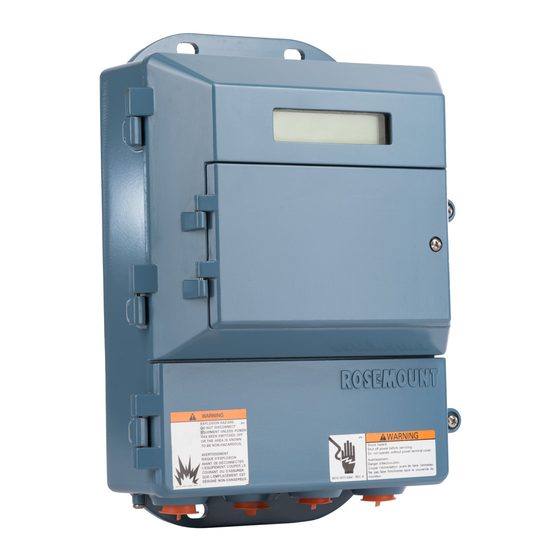
The transmitter can be integrally or remotely mounted from the sensor. This manual is designed to assist in the installation and operation of the Rosemount 8712 Magnetic Flowmeter Transmitter and the Rosemount 8700 Series Magnetic Flowmeter Sensors. www.rosemount.com…
-
Page 10: Safety Messages
Attempting to install and operate the Rosemount 8705, Rosemount 8707 High-Signal, Rosemount 8711, or Rosemount 8721 Magnetic Sensors with the Rosemount 8712 or Rosemount 8732 Magnetic Flowmeter Transmitter without reviewing the instructions contained in this manual could result in personal injury or equipment damage.
-
Page 11: Safety Messages
Verify that the operating environment of the sensor and transmitter is consistent with the appropriate hazardous area approval. Do not connect a Rosemount 8712 to a non-Rosemount sensor that is located in an explosive atmosphere. www.rosemount.com…
-
Page 12: Transmitter Symbols
Installation of this transmitter in an explosive environment must be in accordance with the appropriate local, national, and international standards, codes, and practices. Please review the approvals section of the 8712 reference manual for any restrictions associated with a safe installation.
-
Page 13
Reference Manual 00809-0100-4664, Rev BA Rosemount 8712 January 2010 Figure 2-1. Rosemount 8712 Dimensional Drawing WITH STANDARD COVER 4.31 9.01 (109) (229) 0.44 2.81 3.11 (11) (71) (79) 12.02 (305) 11.15 (283) 2.96 (75) WITH LOI COVER –14 NPT Conduit… -
Page 14: Environmental Considerations
Attach the 8712 to the mounting location using the mounting screws. Identify Options and The standard application of the 8712 includes a 4–20 mA output and control of the sensor coils. Other applications may require one or more of the…
-
Page 15
Connect 4–20 mA Loop External Power Source on page 2-9. Transmitter Security The security switch on the 8712 allows the user to lock out any configuration changes attempted on the transmitter. No changes to the configuration are allowed when the switch is in the ON position. The flow rate indication and totalizer functions remain active at all times. -
Page 16: Conduit Ports And Connections
AC or DC power wiring. • Device must be properly grounded or earthed according to local electric codes. • Rosemount combination cable model number 08712-0752-0001 (ft) or 08712-0752-0003 (m) is required to be used to meet EMC requirements.
-
Page 17: Electrical Considerations
Transmitter Input Power The 8712 transmitter is designed to be powered by 90-250 V AC, 50–60 Hz or 12–42 V DC. The eight digit in the transmitter model number designates the appropriate power supply requirement.
-
Page 18
Reference Manual 00809-0100-4664, Rev BA Rosemount 8712 January 2010 Table 2-1. Length of Annealed Copper (cu) Wires Types of Power Maximum Length of the Wire for Each Supply Wires Corresponding Power Supply Source Wire Annealed Cu 42 V DC 30 V DC 20 V DC 12.5 V DC… -
Page 19: Installation Category
3 Amp, Quick Acting Bussman AGC3 or Equivalent OPTIONS, If the application of the 8712 includes the use of options such as multidrop communications, auxiliary output control, or pulse output, certain CONSIDERATIONS, AND requirements may apply in addition to those previously listed. Be prepared to…
-
Page 20: Connect Pulse Output Power Source
Reference Manual 00809-0100-4664, Rev BA Rosemount 8712 January 2010 Internal The 4–20 mA analog power loop may be powered from the transmitter itself. Resistance in the loop must be 1,000 ohms or less. If a Handheld Communicator or control system will be used, it must be connected across a minimum of 250 ohms resistance in the loop.
-
Page 21: Connect Auxiliary Channel 1
Reference Manual 00809-0100-4664, Rev BA Rosemount 8712 January 2010 The pulse output option requires an external power source. Complete the following steps to connect an external power supply. Ensure that the power source and connecting cable meet the requirements outlined previously.
-
Page 22: Connect Auxiliary Channel 2
Reference Manual 00809-0100-4664, Rev BA Rosemount 8712 January 2010 When configured as an output, the following requirements apply: Supply Voltage: 5 to 28V DC Maximum Power: 2 watts Switch Closure: optically isolated solid state switch When using channel 1 as a digital output, the power source must be connected to the transmitter.
-
Page 23: Sensor Connections
This section covers the steps required to physically install the transmitter including wiring and calibration. Rosemount Sensors To connect the transmitter to a non-Rosemount sensor, refer to the appropriate wiring diagram in Appendix D: Wiring Diagrams. The calibration procedure listed is not required for use with Rosemount sensors.
-
Page 24: Conduit Cables
For remote mount installations, combination signal and coil drive cable should be limited to less than 300 ft. (100 m). Rosemount recommends using the combination signal and coil drive for N5, E5 approved sensors for optimum performance.
-
Page 25: Sensor To Remote Mount Transmitter Connections
Connect coil drive and electrode cables as shown in Figure 2-13. Transmitter Connections Do not connect AC power to the sensor or to terminals 1 and 2 of the transmitter, or replacement of the electronics board will be necessary. Figure 2-13. Wiring Diagram Rosemount 8712 Transmitter Rosemount 8705/8707/8711/8721 sensors 2-15…
-
Page 26: Rev Ba Rosemount
Reference Manual 00809-0100-4664, Rev BA Rosemount 8712 January 2010 2-16…
-
Page 27: Introduction
“Universal Sensor Wiring Diagrams” on page E-1. The Rosemount 8712 features a full range of software functions for configuration of output from the transmitter. Software functions are accessed through the LOI, AMS, a Handheld Communicator, or a control system.
-
Page 28: Local Operator Interface
Refer to Section 6 «Maintenance and Troubleshooting» for further information. LOCAL OPERATOR The optional Local Operator Interface (LOI) provides an operator communications center for the 8712. By using the LOI, the operator can INTERFACE access any transmitter function for changing configuration parameter settings, checking totalized values, or other functions.
-
Page 29: Basic Features
Transmitter Parameter Keys The transmitter parameter keys provide direct access to the most common transmitter parameters and stepped access to the advanced functions of the 8712 through the AUX. FUNCTION key. Figure 3-1. Local Operator Interface Keypad DATA…
-
Page 30: Selecting Options
Reference Manual 00809-0100-4664, Rev BA Rosemount 8712 January 2010 Selecting Options To select pre-defined software options on the LOI, use the following procedure: Access the appropriate option. Use SHIFT or INCR. to toggle between the applicable choices. Press ENTER when the desired choice is displayed on the screen.
-
Page 31
Function Performed Keys Tube Cal No. Identifies the calibration number when using Rosemount sensors, or other manufacturers’ sensors calibrated at the Rosemount factory Tube Size Specifies the sensor size and identifies the corresponding maximum flow (0.1 — through 80-inch line sizes) -
Page 32: Diagnostic Messages
• Totalizer indicator (A flashing letter “T” on the LOI indicates to totalizer is activated) Review The 8712 includes a capability that enables you to review the configuration variable settings. Fast Keys 1, 5 The flowmeter configuration parameters set at the factory should be reviewed to ensure accuracy and compatibility with your particular application of the flowmeter.
-
Page 33: Pv — Primary Variable
Reference Manual 00809-0100-4664, Rev BA Rosemount 8712 January 2010 PV — Primary Variable The Primary Variable shows the current measured flow rate. This value determines the analog output from the transmitter. Fast Keys 1, 1, 1 LOI Key FLOW RATE…
-
Page 34: Pulse Output
The Pulse Output displays the current value of the pulse signal. Fast Keys 1, 1, 5 BASIC SETUP The basic configuration functions of the Rosemount 8712 must be set for all applications of the transmitter in a magnetic flowmeter system. If your Fast Keys 1, 3 application requires the advanced functionality features of the Rosemount 8712, see Section 4 «Operation»…
-
Page 35
(see “Flow Units” on page 3-8). If your application has special needs and the standard configurations do not apply, the Rosemount 8712 provides the flexibility to configure the transmitter in a custom-designed units format using the special units variable. -
Page 36: Line Size
The actual special units setting you define will not appear. Four characters are available to store the new units designation. The 8712 LOI will display the four character designation as configured.
-
Page 37: Pv Urv (Upper Range Value)
Reference Manual 00809-0100-4664, Rev BA Rosemount 8712 January 2010 PV URV The upper range value (URV), or analog output range, is preset to 30 ft/s at the factory. The units that appear will be the same as those selected under the (Upper Range Value) units parameter.
-
Page 38: Calibration Number
Rosemount flow lab, accuracy of the system may be compromised. If your sensor is not a Rosemount sensor and was not calibrated at the Rosemount factory, contact your Rosemount representative for assistance. If your sensor is imprinted with an eight-digit number or a k-factor, check in the sensor wiring compartment for the sixteen-digit calibration number.
-
Page 39: Introduction
This section contains information for advanced configuration parameters and diagnostics. The software configuration settings for the Rosemount 8712 can be accessed through a HART-based communicator, Local Operator Interface (LOI), or through a control system. The software functions for the Field Communicator are described in detail in this section of the manual.
-
Page 40: Basic Diagnostics
For more details on the electronics temperature diagnostic, see Appendix C: «Diagnostics». Basic Diagnostics The basic diagnostics menu contains all of the standard diagnostics and tests that are available in the 8712 transmitter. Field Comm. 1, 2, 2 Self Test Field Comm.
-
Page 41
1, 2, 2, 2, 3 Send the analog output into an alarm mA value. Actual mA value depends on the alarm configuration. • Rosemount Standard High Alarm – 22.6 mA • Rosemount Standard Low Alarm – 3.75 mA • Namur Compliant High Alarm – 22.6 mA •… -
Page 42
Reference Manual 00809-0100-4664, Rev BA Rosemount 8712 January 2010 Empty Pipe Trigger Level Field Comm. 1, 2, 2, 4, 2 LOI Key AUX. FUNCTION Limits: 3 to 2000 Configure the threshold limit that the empty pipe value must exceed before the diagnostic alert activates. -
Page 43
Reference Manual 00809-0100-4664, Rev BA Rosemount 8712 January 2010 In Range – The HART Alert will activate when the measured flow rate is between the High Limit 1 and Low Limit 1 set points. Out of Range – The HART Alert will activate when the measured flow rate exceeds the High Limit 1 set point or falls below the Low Limit 1 set point. -
Page 44
Reference Manual 00809-0100-4664, Rev BA Rosemount 8712 January 2010 High Limit 2 Field Comm. 1, 2, 2, 7, 3 Set the flow rate value that corresponds to the high limit set point for the Flow Limit 2 alert. If a digital output is configured for Flow Limit 1, the digital output will activate when the conditions for mode 1 are met. -
Page 45: Advanced Diagnostics
Alert status. Advanced Diagnostics The advanced diagnostics menu contains information on all of the additional diagnostics and tests that are available in the 8712 transmitter if one of the Field Comm. 1, 2, 3 diagnostics suite packages was ordered.
-
Page 46
Reference Manual 00809-0100-4664, Rev BA Rosemount 8712 January 2010 8714i Results Field Comm. 1, 2, 3, 1, 2 LOI Key XMTR INFO Review the results of the most recently performed 8714i Meter Verification test. Information in this section details the measurements taken and if the meter passed the verification test. -
Page 47
Have the transmitter measure and store the sensor signature values. These values will then be used as the baseline for the meter verification test. Use this when connecting to older Rosemount or another manufacturers sensors, or installing the magnetic flowmeter system for the first time. For more details… -
Page 48
Reference Manual 00809-0100-4664, Rev BA Rosemount 8712 January 2010 Recall Last Saved Values Field Comm. 1, 2, 3, 1, 3, 3 LOI Key AUX. FUNCTION Recalls the last saved “good” values for the sensor signature. Set Pass/Fail Criteria Field Comm. -
Page 49
Reference Manual 00809-0100-4664, Rev BA Rosemount 8712 January 2010 Coil Signature Field Comm. 1, 2, 3, 1, 5, 2 View the measured value for the coil signature taken during the 8714i meter verification test. Electrode Resistance Field Comm. 1, 2, 3, 1, 5, 3 View the measured value for the electrode resistance taken during the 8714i meter verification test. -
Page 50: Diagnostic Variable Values
Reference Manual 00809-0100-4664, Rev BA Rosemount 8712 January 2010 Diagnostic Variable From this menu, all of the diagnostic variable values can be reviewed. This information can be used to get more information about the transmitter, sensor, Values and process, or to get more detail about an alert that may have activated.
-
Page 51
Reference Manual 00809-0100-4664, Rev BA Rosemount 8712 January 2010 8714i Test Result Field Comm. 1, 2, 3, 7, 3 Displays the results of the 8714i Meter Verification test as pass or fail. For more details on this parameter see Appendix C: «Diagnostics». -
Page 52: Trims
Digital trim is the function by which the factory calibrates the transmitter. This procedure is rarely needed by users. It is only necessary if you suspect the Rosemount 8712 is no longer accurate. A Rosemount 8714D Calibration Standard is required to complete a digital trim. Attempting a digital trim without a Rosemount 8714D Calibration Standard may result in an inaccurate transmitter or an error message.
-
Page 53
“DIGITAL TRIM FAILURE” message may appear. If this message occurs, no values were changed in the transmitter. Simply power down the Rosemount 8712 to clear the message. To simulate a nominal sensor with the Rosemount 8714D Calibration… -
Page 54: Status
LOI Key XMTR INFO ADVANCED In addition to the basic configuration options and the diagnostic information and controls, the 8712 has many advanced functions that can also be CONFIGURATION configured as required by the application. DETAILED SETUP The detailed setup function provides access to other parameters within the transmitter that can be configured such as coil drive frequency, output Field Comm.
-
Page 55: Configure Outputs
Reference Manual 00809-0100-4664, Rev BA Rosemount 8712 January 2010 Density Value Field Comm. 1, 4, 1, 2 LOI Key AUX. FUNCTION The density value is used to convert from a volumetric flow rate to a mass flow rate using the following equation:…
-
Page 56
Field Comm. 1, 4, 2, 1, 4 The analog output alarm type displays the alarm mode the 8712 is currently set for. This value is set by a switch on the electronics board. There are two available options for this setting: •… -
Page 57
Reference Manual 00809-0100-4664, Rev BA Rosemount 8712 January 2010 Loop Test Field Comm. 1, 4, 2, 1, 5 LOI Key AUX. FUNCTION The loop test allows you to drive the transmitter output to a desired electrical current output on terminals 1 and 2. This capability allows you to check the entire current loop prior to start-up. -
Page 58
10,000 Hz. With the 110 percent overrange capability, the absolute limit is 11,000 Hz. For example, if you want the Rosemount 8712 to pulse every time 0.01 gallons pass through the sensor, and the flow rate is 10,000 gal/min, you will exceed the 10,000 Hz full-scale limit: … -
Page 59
Reference Manual 00809-0100-4664, Rev BA Rosemount 8712 January 2010 The best choice for this parameter depends upon the required resolution, the number of digits in the totalizer, the extent of range required, and the maximum counter external frequency. NOTE For totalizing on the LOI, ten digits are available. -
Page 60
Reference Manual 00809-0100-4664, Rev BA Rosemount 8712 January 2010 Example The maximum flow rate is 10,000 gpm. Set the pulse output scaling such that the transmitter outputs 10,000 Hz at 10,000 gpm. Flow Rate (gpm) Pulse Scaling ———————————————————- — (60 s/min)(Frequency) -
Page 61
AUX. FUNCTION This menu is used to configure the optional digital input and digital output parameters of the 8712 transmitter. Note that this configuration option is only active if the auxiliary output suite (option code AX) was ordered or licensed in the field. -
Page 62
Reference Manual 00809-0100-4664, Rev BA Rosemount 8712 January 2010 DIO 1 Control Field Comm. 1, 4, 2, 3, 1, 2 Displays the configuration for Channel 1 as either a discrete Input or Output. Digital Input 1 Field Comm. 1, 4, 2, 3, 1, 3 Displays what digital input Channel 1 will be set to when the Control for Channel 1 is set to Input. -
Page 63
Reference Manual 00809-0100-4664, Rev BA Rosemount 8712 January 2010 Control 1 Field Comm. 1, 4, 2, 3, 3, 1 Turns the Flow Limit 1 HART Alert ON or OFF. ON – The transmitter will generate a HART alert when the defined conditions are met. -
Page 64
Reference Manual 00809-0100-4664, Rev BA Rosemount 8712 January 2010 ON – The transmitter will generate a HART alert when the defined conditions are met. If a digital output is configured for Flow Limit 1, the digital output will activate when the conditions for mode 1 are met. -
Page 65
Reference Manual 00809-0100-4664, Rev BA Rosemount 8712 January 2010 Total Mode Field Comm. 1, 4, 2, 3, 5, 2 Mode that determines when the Total Limit HART Alert will activate. > High Limit – The HART Alert will activate when the measured net total exceeds the Total High Limit set point. -
Page 66
Reference Manual 00809-0100-4664, Rev BA Rosemount 8712 January 2010 Totalizer Units Field Comm. 1, 4, 2, 5, 1 LOI Key AUX. FUNCTION Totalizer units allow for the configuration of the units that the totalized value will be displayed as. These units are independent of the flow units. -
Page 67
The alarm level allows you to drive the transmitter to preset values if an alarm occurs. There are two options: • Rosemount Alarm and Saturation Values • NAMUR-Complaint Alarm and Saturation Levels Table 4-3. Rosemount (Standard) Alarm and Saturation Values Level 4-20 mA Saturation 4-20 mA Alarm 3.75 mA 3.9 mA 22.6 mA… -
Page 68
Rosemount 8712 in the loop. NOTE The Rosemount 8712 is set to poll address zero at the factory, allowing it to operate in the standard point-to-point manner with a 4–20 mA output signal. To activate multidrop communication, the transmitter poll address must be changed to a number between 1 and 15. -
Page 69: Loi Configuration
Forward Total and Reverse Total • Net Total and Gross Total Signal Processing The 8712 contains several advanced functions that can be used to stabilize erratic outputs caused by process noise. The signal processing menu Field Comm. 1, 4, 4 LOI Key AUX.
-
Page 70
Field Comm. 1, 4, 4, 2, 1 When ON is selected, the Rosemount 8712 output is derived using a running average of the individual flow inputs. Signal processing is a software algorithm that examines the quality of the electrode signal against user-specified tolerances. -
Page 71
10 seconds. In some cases this may be unacceptable. By setting the time limit, you can force the 8712 to clear the value of the running average and re-establish the output and average at the new flow rate once the time limit has elapsed. -
Page 72: Universal Auto Trim
00809-0100-4664, Rev BA Rosemount 8712 January 2010 Universal Auto Trim The universal auto trim function enables the Rosemount 8712 to calibrate sensors that were not calibrated at the Rosemount factory. The function is Field Comm. 1, 4, 5 LOI Key AUX.
-
Page 73
Revisions numbers are fixed informational variables that provide the revision number for different elements of your Field Communicator and Rosemount 8712. These revision numbers may be required when calling the factory for support. Revision numbers can only be changed at the factory and are… -
Page 74
Reference Manual 00809-0100-4664, Rev BA Rosemount 8712 January 2010 Software Revision Number Field Comm. 1, 4, 6, 10, 3 This function displays the software revision number of the transmitter. This is one piece of information required to generate a license code to enable diagnostics in the field. -
Page 75
Reference Manual 00809-0100-4664, Rev BA Rosemount 8712 January 2010 Flange Material Field Comm. 1, 4, 6, 11, 2 LOI Key XMTR INFO Flange material enables you to select the flange material for your magnetic transmitter system. This variable only needs to be changed if you have changed your sensor. -
Page 76
Reference Manual 00809-0100-4664, Rev BA Rosemount 8712 January 2010 Liner Material Field Comm. 1, 4, 6, 11, 5 LOI Key XMTR INFO Liner material enables you to select the liner material for the attached sensor. This variable only needs to be changed if you have replaced your sensor. -
Page 77
Reference Manual 00809-0100-4664, Rev BA Rosemount 8712 January 2010 Figure 4-2. Field Communicator Menu Tree for the Rosemount 8712 4-39… -
Page 78
Reference Manual 00809-0100-4664, Rev BA Rosemount 8712 January 2010 Figure 4-3. HART Fast Key Function HART Fast Keys Process Variables (PV) Primary Variable Value 1,1,1 Primary Variable % 1,1,2 PV Loop Current 1,1,3 Totalizer Set-Up 1,1,4 Totalizer Units 1,1,4,1 Gross Total… -
Page 79
Reference Manual 00809-0100-4664, Rev BA Rosemount 8712 January 2010 Function HART Fast Keys Sensor Cal Test Result 1,2,3,1,2,9 Coil Circuit Test Result 1,2,3,1,2,x Electrode Circuit Test Result 1,2,3,1,2,x Sensor Signature 1,2,3,1,3 Signature Values 1,2,3,1,3,1 Coil Resistance 1,2,3,1,3,1,1 Coil Signature 1,2,3,1,3,1,2… -
Page 80
Reference Manual 00809-0100-4664, Rev BA Rosemount 8712 January 2010 Function HART Fast Keys Base Volume Unit 1,3,2,2,2 Conversion Number 1,3,2,2,3 Base Time Unit 1,3,2,2,4 Flow Rate Unit 1,3,2,2,5 Line Size 1,3,3 PV URV 1,3,4 PV LRV 1,3,5 Calibration Number 1,3,6… -
Page 81
Reference Manual 00809-0100-4664, Rev BA Rosemount 8712 January 2010 Function HART Fast Keys Diagnostic Status Alert 1,4,2,3,6 Reverse Flow 1,4,2,4 Totalizer Setup 1,4,2,5 Totalizer Units 1,4,2,5,1 Gross Total 1,4,2,5,2 Net Total 1,4,2,5,5 Reverse Total 1,4,2,5,4 Start Totalizer 1,4,2,5,5 Stop Totalizer… -
Page 82
Function Performed Keys Tube Cal No. Identifies the calibration number when using Rosemount sensors, or other manufacturers’ sensors calibrated at the Rosemount factory Tube Size Specifies the sensor size and identifies the corresponding maximum flow (0.1 — through 80-inch line sizes) -
Page 83
Reference Manual 00809-0100-4664, Rev BA Rosemount 8712 January 2010 Auxiliary Functions Function Options Run 8714i Runs the meter verification diagnostic Operating Mode Normal or Filter Coil Pulse Mode 5 or 37 Hz Flow rate Display Flow–% Span, Flow–Totalize, %Span–Totalize Totalizer Display Forward–Reverse or Net–Gross… -
Page 84
Reference Manual 00809-0100-4664, Rev BA Rosemount 8712 January 2010 4-46… -
Page 85: Safety Messages
Verify that the operating environment of the sensor and transmitter is consistent with the appropriate hazardous area approval. Do not connect a Rosemount 8712 to a non-Rosemount sensor that is located in an explosive atmosphere. www.rosemount.com…
-
Page 86
Installation of this transmitter in an explosive environment must be in accordance with the appropriate local, national, and international standards, codes, and practices. Please review the approvals section of the 8712 reference manual for any restrictions associated with a safe installation. -
Page 87: Sensor Handling
Figure 5-1 shows sensors correctly supported for handling and installation. Notice the plywood end pieces are still in place to protect the sensor liner during transportation. Figure 5-1. Rosemount 8705 Sensor Support for Handling 6-Inch and Larger ½- through 4-Inch…
-
Page 88: Sensor Mounting
Reference Manual 00809-0100-4664, Rev BA Rosemount 8712 January 2010 SENSOR MOUNTING Physical mounting of a sensor is similar to installing a typical section of pipe. Conventional tools, equipment, and accessories (bolts, gaskets, and grounding hardware) are required. Upstream/Downstream To ensure specification accuracy over widely varying process conditions,…
-
Page 89
Orientation FLOW The electrodes in the Rosemount 8711 are properly oriented when the top of the sensor is either vertical or horizontal, as shown in Figure 5-6. Avoid any mounting orientation that positions the top of the sensor at 45 degrees from… -
Page 90: Flow Direction
Reference Manual 00809-0100-4664, Rev BA Rosemount 8712 January 2010 Figure 5-6. Rosemount 8711 Mounting Position 45° Electrode Plane 45° Electrode Plane Flow Direction The sensor should be mounted so that the FORWARD end of the flow arrow, shown on the sensor identification tag, points in the direction of flow through the tube (see Figure 5-7).
-
Page 91: Installation (Flanged Sensor)
The following section should be used as a guide in the installation of the flange-type Rosemount 8705 and Rosemount 8707 High-Signal Sensors. (FLANGED SENSOR) Refer to page 5-10 for installation of the wafer-type Rosemount 8711 Sensor. Gaskets The sensor requires a gasket at each of its connections to adjacent devices or piping.
-
Page 92
All sensors require a second torquing 24 hours after initial flange bolt tightening. Table 5-1. Flange Bolt Torque Specifications for Rosemount 8705 and 8707 High-Signal Sensors PTFE/ETFE liner Polyurethane liner Class 150… -
Page 93
Reference Manual 00809-0100-4664, Rev BA Rosemount 8712 January 2010 Table 5-2. Flange Bolt Torque and Bolt Load Specifications for Rosemount 8705 PTFE/ETFE liner PN10 PN 16 PN 25 PN 40 Size Code Line Size (Newton-meter) (Newton) (Newton-meter) (Newton) (Newton-meter) (Newton) (Newton-meter) (Newton) -
Page 94: Installation (Wafer Sensor)
Reference Manual 00809-0100-4664, Rev BA Rosemount 8712 January 2010 Table 5-3. Flange Bolt Torque and Bolt Load Specifications for Rosemount 8705 Polyurethane Liner PN 10 PN 16 PN 25 PN 40 Size Code Line Size (Newton-meter) (Newton) (Newton-meter) (Newton) (Newton-meter) (Newton) (Newton-meter) (Newton)
-
Page 95: Flange Bolts
Reference Manual 00809-0100-4664, Rev BA Rosemount 8712 January 2010 Table 5-4. Stud Specifications Nominal Sensor Size Stud Specifications 0.15 – 1 inch (4 – 25 mm) 316 SST ASTM A193, Grade B8M Class 1 threaded mounted studs – 8 inch (40 – 200 mm) CS, ASTM A193, Grade B7, threaded mounting studs Place the sensor between the flanges.
-
Page 96: Installation (Sanitary Sensor)
The sensor requires a gasket at each of its connections to adjacent devices or piping. The gasket material selected must be compatible with the process fluid and operating conditions. Gaskets are supplied with all Rosemount 8721 Sanitary sensors except when the process connection is an IDF sanitary screw type.
-
Page 97
Reference Manual 00809-0100-4664, Rev BA Rosemount 8712 January 2010 NOTE Consult factory for installations requiring cathodic protection or situations where there are high currents or high potential in the process. The sensor case should always be earth grounded in accordance with national and local electrical codes. -
Page 98
Reference Manual 00809-0100-4664, Rev BA Rosemount 8712 January 2010 Figure 5-14. Grounding with Grounding Rings or Lining Protectors Grounding Rings or Lining Protectors Figure 5-15. Grounding with Grounding Rings or Lining Protectors Grounding Rings or Lining Protectors 5-14… -
Page 99: Process Leak Protection (Optional)
Figure 5-16. Grounding with Grounding Electrodes PROCESS LEAK The Rosemount 8705 and 8707 High-Signal Sensor housing is fabricated from carbon steel to perform two separate functions. First, it provides PROTECTION shielding for the sensor magnetics so that external disturbances cannot (OPTIONAL) interfere with the magnetic field and thus affect the flow measurement.
-
Page 100: Relief Valves
Reference Manual 00809-0100-4664, Rev BA Rosemount 8712 January 2010 Figure 5-17. Standard Housing Configuration — Sealed Welded Housing (Option Code W0) –14 NPT Conduit Connection (no relief valve) Relief Valves The first optional configuration, identified by the W1 in the model number option code, uses a completely welded coil housing.
-
Page 101: Process Leak Containment
Reference Manual 00809-0100-4664, Rev BA Rosemount 8712 January 2010 Process Leak The second optional configuration, identified as option code W3 in the model number, divides the coil housing into three compartments: one for each Containment electrode and one for the coils. Should a damaged liner or electrode fault allow process fluid to migrate behind the electrode seals, the fluid is contained in the electrode compartment.
-
Page 102
Reference Manual 00809-0100-4664, Rev BA Rosemount 8712 January 2010 5-18… -
Page 103: Safety Information
FM or CSA approval. Do not connect a Rosemount 8712 to a non-Rosemount sensor that is located in an explosive atmosphere. Mishandling products exposed to a hazardous substance may result in death or serious injury.
-
Page 104: Installation Check And Guide
Reference Manual 00809-0100-4664, Rev BA Rosemount 8712 January 2010 INSTALLATION CHECK Use this guide to check new installations of Rosemount magnetic flowmeter systems that appear to malfunction. AND GUIDE Before You Begin Transmitter Apply power to your system before making the following transmitter checks.
-
Page 105: Diagnostic Messages
Problems in the magnetic flowmeter system are usually indicated by incorrect output readings from the system, error messages, or failed tests. Consider all MESSAGES sources in identifying a problem in your system. Table 6-1. Rosemount 8712 Basic Diagnostic Messages Message Potential Cause Corrective Action “Empty Pipe”…
-
Page 106
Calibrator is not set to 30 FPS Change calibrator setting to 30 FPS Bad calibrator Replace calibrator Table 6-2. Rosemount 8712 Advanced Diagnostic Messages (Suite 1 — Option Code DA1) Message Potential Cause Corrective Action Grounding/Wiring Fault Improper installation of wiring See “Sensor to Remote Mount Transmitter Connections”… -
Page 107
Reference Manual 00809-0100-4664, Rev BA Rosemount 8712 January 2010 Table 6-4. Basic Troubleshooting–Rosemount 8712 Symptom Potential Cause Corrective Action Output at 0 mA No power to transmitter Check power source and connections to the transmitter Blown fuse Check the fuse and replace with an appropriately rated fuse, if necessary… -
Page 108: Transmitter Troubleshooting
Reference Manual 00809-0100-4664, Rev BA Rosemount 8712 January 2010 TRANSMITTER TROUBLESHOOTING Table 6-5. Advanced Troubleshooting–Rosemount 8712 Symptom Potential Cause Corrective Action Does not appear to be within Transmitter, control system, or other Check all configuration variables for the transmitter, sensor,…
-
Page 109
Sensor calibration number Units Line size Electrode coating Use bulletnose electrodes in the Rosemount 8705 Sensor. Downsize the sensor to increase the flow rate above 3 ft/s. Periodically clean the sensor Air in line Move the sensor to another location in the process line to… -
Page 110: Quick Troubleshooting
To interpret the results, the hazardous location certification for the sensor must be known. Applicable codes for the Rosemount 8705 are N0, N5, and KD. Applicable codes for the Rosemount 8707 are N0 and N5. Applicable codes for the Rosemount 8711 are N0, N5, E5, and CD.
-
Page 111
Reference Manual 00809-0100-4664, Rev BA Rosemount 8712 January 2010 Table 6-6. Sensor Test Sensor Required Measuring at Test Location Equipment Connections Expected Value Potential Cause Corrective Action A. Sensor Installed or Multimeter 1 and 2 = R 2… -
Page 112: Step 4: Uninstalled Sensor Tests
Sensor Tests be known. Applicable codes for the Rosemount 8705 are N0, N5, and KD. Applicable codes for the Rosemount 8707 are N0 and N5. Applicable codes for the Rosemount 8711 are N0, N5, E5, and CD.
-
Page 113
Measure both electrodes. One electrode should result in an open reading, while the other electrode should be less than 275 Table 6-8. Uninstalled Rosemount 8711 Wafer Sensor Tests Hazardous Location Certification Measuring at Connections N5, E5, CD 18 and Electrode … -
Page 114
Reference Manual 00809-0100-4664, Rev BA Rosemount 8712 January 2010 6-12… -
Page 115: Functional Specifications
Physical Specifications ……page A-8 Rosemount 8712E Ordering Information … . . page A-9…
-
Page 116
Reference Manual 00809-0100-4664, Rev BA Rosemount 8712 January 2010 DC Load Limitations (Analog Output) Maximum loop resistance is determined by the voltage level of the external power supply, as described by: FIGURE 1. DC Load Limitations 1250 1000 Operating Region 10.8… -
Page 117
Reference Manual 00809-0100-4664, Rev BA Rosemount 8712 January 2010 Humidity Limits 0–100% RH to 120 °F (49 °C), decreases linearly to 10% RH at 130 °F (54 °C) Enclosure Rating Type 4X, IP66 Output Signals Analog Output Adjustment 4–20 mA, switch-selectable as internally or externally powered 5 to 24 V DC;… -
Page 118
Reference Manual 00809-0100-4664, Rev BA Rosemount 8712 January 2010 Flow Limits (2): Activates switch closure output when the transmitter measures a flow rate that meets the conditions established for this alert. There are two independent flow limit alerts that can be configured as discrete outputs. -
Page 119
Damping Adjustable between 0.0 and 256 seconds Sensor Compensation Rosemount sensors are flow-calibrated and assigned a calibration factor at the factory. The calibration factor is entered into the transmitter, enabling interchangeability of sensors without calculations or a compromise in accuracy. -
Page 120: Performance Specifications
Includes the combined effects of linearity, hysteresis, repeatability, and calibration uncertainty. Rosemount 8712E with 8705/8707 Sensor: Standard system accuracy is ±0.25% of rate ±1.0 mm/sec from 0.04 to 6 ft/s (0.01 to 2 m/s); above 6 ft/s (2 m/s), the system has an accuracy of ±0.25% of rate ±1.5 mm/sec.
-
Page 121
0.04 and 3.0 ft/s (0.01 and 1 m/s), the system has an accuracy of ±0.015 ft/s (0.005 m/s). Rosemount 8712E with Other Manufacturers’ Sensors: When calibrated in the Rosemount Flow Facility, system accuracies as good as 0.5% of rate can be attained. There is no accuracy specification for other manufacturers’ sensors calibrated in the process line. -
Page 122: Physical Specifications
Reference Manual 00809-0100-4664, Rev BA Rosemount 8712 January 2010 PHYSICAL Materials of Construction SPECIFICATIONS Housing Low-copper aluminum, Type 4X and IEC 60529 IP66 Paint Polyurethane Cover Gasket Rubber Electrical Connections Four –14 NPT connections provided on the base of the transmitter. Screw terminals provided for all of the connections.
-
Page 123: Rosemount 8712E Ordering Information
Reference Manual 00809-0100-4664, Rev BA Rosemount 8712 January 2010 ROSEMOUNT 8712E ORDERING INFORMATION Model Product Description 8712E Remote Magnetic Flowmeter Transmitter Code Transmitter Style Standard Code Transmitter Mount Remote Mount for 2 in. pipe or panel (includes CS mounting bolts and 316L SST bracket)
-
Page 124
Reference Manual 00809-0100-4664, Rev BA Rosemount 8712 January 2010 QIG Language Danish Dutch French German Finnish Italian Norwegian Portuguese Spanish Russian Swedish Typical Model Number: 8712E S R 1 A 1 N0 DA1 DA2 M4 (1) Adapter are used for this conduit entry type… -
Page 125: Product Certifications
PRODUCT CERTIFICATIONS APPROVED Rosemount Inc. — Eden Prairie, Minnesota, USA MANUFACTURING Fisher-Rosemount Technologias de Flujo, S.A. de C.V. — Chihuahua Mexico LOCATIONS Emerson Process Management Flow — Ede, The Netherlands Asia Flow Technology Center — Nanjing, China European Directive The EC declaration of conformity can be found in document number 00825-0100-4664.
-
Page 126: Sensor Approval Information
Reference Manual 00809-0100-4664, Rev BA Rosemount 8712 January 2010 Canadian Standards Association (CSA) Non-incendive for Class I, Division 2, Groups A, B, C, and D non-flammable fluids (T4 at 40 °C), and Dust-ignition proof Class II/III, Division 1, Groups E, F, and G (T4 at 40 °C) Hazardous locations;…
-
Page 127
Reference Manual 00809-0100-4664, Rev BA Rosemount 8712 January 2010 North American Certifications Factory Mutual (FM) Non-incendive for Class I, Division 2, Groups A, B, C, and D non-flammable fluids (8705/8711 T5 at 60 °C; 8707 T3C at 60 °C), and Dust-ignition proof Class II/III, Division 1, Groups E, F, and G (8705/8711 T6 at 60 °C;… -
Page 128
A fuse with a rating of maximum 0,7 A according to IEC 60127-1 shall be included in the coil excitation circuit if the sensors are used with other flow transmitters. Table B-1. Electrical Data Rosemount 8705 and 8711 Sensors Coil excitation 40 V, 0,5 A, 20 W maximum… -
Page 129
Reference Manual 00809-0100-4664, Rev BA Rosemount 8712 January 2010 Table B-3. Relation between the maximum ambient temperature, the maximum process temperature, and the temperature class Maximum Maximum process temperature °F (°C) per temperature class Ambient Temperature 0.5 in. sensor size 149°F (65°C) -
Page 130
Reference Manual 00809-0100-4664, Rev BA Rosemount 8712 January 2010 Table B-3. Relation between the maximum ambient temperature, the maximum process temperature, and the temperature class Maximum Maximum process temperature °F (°C) per temperature class Ambient Temperature 2.0 in. sensor size 149°F (65°C) -
Page 131
Reference Manual 00809-0100-4664, Rev BA Rosemount 8712 January 2010 Figure B-1. CSA Installation… -
Page 132
Reference Manual 00809-0100-4664, Rev BA Rosemount 8712 January 2010 Figure B-2. Factory Mutual Hazardous Locations… -
Page 133: Diagnostic Availability
Rosemount magmeter diagnostics can be accessed through the Local Operator Interface (LOI), the 375 Handheld Communicator, and AMS Device Manager. Access Diagnostics through the LOI for quicker installation, maintenance, and meter verification Rosemount magmeter diagnostics are available through the LOI to make maintenance of every magmeter easier. www.rosemount.com…
-
Page 134: Licensing And Enabling
ENABLING diagnostics can be licensed in the field through the use of a license key. To obtain a license key, contact your local Rosemount Representative. Each transmitter has a unique license key specific to the diagnostic option code. See the detailed procedures below for entering the license key and enabling the advanced diagnostics.
-
Page 135: Tunable Empty Pipe Parameters
Reference Manual 00809-0100-4664, Rev BA Rosemount 8712 January 2010 Tunable Empty Pipe The Tunable Empty Pipe diagnostic has one read-only parameter, and two parameters that can be custom configured to optimize the diagnostic Parameters performance. Empty Pipe Value HART Fast Keys…
-
Page 136: Troubleshooting Empty Pipe
Reference Manual 00809-0100-4664, Rev BA Rosemount 8712 January 2010 Example Set the counts to 10 Troubleshooting Empty The following actions can be taken if Empty Pipe detection is unexpected. Pipe Verify the sensor is full. Verify that the sensor has not been installed with a measurement electrode at the top of the pipe.
-
Page 137: Troubleshooting Ground/Wiring Fault
Reference Manual 00809-0100-4664, Rev BA Rosemount 8712 January 2010 Troubleshooting The transmitter detected high levels of 50/60 Hz noise caused by improper wiring or poor process grounding. Ground/Wiring Fault Verify that the transmitter is earth grounded. Connect ground rings, grounding electrode, lining protector, or grounding straps.
-
Page 138: High Process Noise Parameters
Reference Manual 00809-0100-4664, Rev BA Rosemount 8712 January 2010 High Process Noise The High Process Noise diagnostic has two read-only parameters. It does not have any configurable parameters. This diagnostic requires that flow be Parameters present in the pipe and the velocity be > 1 ft/s.
-
Page 139: High Process Noise Functionality
Rosemount High-Signal 8707 sensor be used. These sensors can be calibrated to run at lower coil drive current supplied by the standard Rosemount transmitters, but can also be upgraded by changing to the 8712H High-Signal transmitter.
-
Page 140: 8714I Meter Verification
Reference Manual 00809-0100-4664, Rev BA Rosemount 8712 January 2010 The transmitter continuously monitors signal amplitudes over a wide range of frequencies. For the high process noise diagnostic, the transmitter specifically looks at the signal amplitude at frequencies of 2.5 Hz, 7.5 Hz, 32.5 Hz, and 42.5 Hz.
-
Page 141: 8714I Meter Verification Test Parameters
Reference Manual 00809-0100-4664, Rev BA Rosemount 8712 January 2010 8714i Meter Verification The 8714i has a multitude of parameters that set the test criteria, test conditions, and scope of the calibration verification test. Test Parameters Test Conditions for the 8714i Meter Verification There are three possible test conditions that the 8714i Meter Verification test can be initiated under.
-
Page 142: 8714I Meter Verification Test Results Parameters
Reference Manual 00809-0100-4664, Rev BA Rosemount 8712 January 2010 Empty Pipe Set the test criteria for the Empty Pipe condition. The factory default for this value is set to three percent with limits configurable between one and ten percent. HART Fast Keys…
-
Page 143
Reference Manual 00809-0100-4664, Rev BA Rosemount 8712 January 2010 Viewing the 8714i Meter Verification Results Depending on the method used to view the results, they will be displayed in either a menu structure, as a method, or in the report format. When using the HART Field Communicator, each individual component can be viewed as a menu item. -
Page 144
Reference Manual 00809-0100-4664, Rev BA Rosemount 8712 January 2010 Actual Velocity Displays the velocity measured by the transmitter during the transmitter calibration verification process. HART Fast Keys 1,2,3,3,2,5 LOI Key XMTR INFO Context Menu, Device Diagnostics, 8714i Report Velocity Deviation Displays the deviation in the actual velocity compared to the simulated velocity in terms of a percentage. -
Page 145: Optimizing The 8714I Meter Verification
Reference Manual 00809-0100-4664, Rev BA Rosemount 8712 January 2010 Optimizing the 8714i The 8714i Meter Verification diagnostic can be optimized by setting the test criteria to the desired levels necessary to meet the compliance requirements Meter Verification of the application. The following examples below will provide some guidance on how to set these levels.
-
Page 146: Troubleshooting The 8714I Meter Verification Test
Reference Manual 00809-0100-4664, Rev BA Rosemount 8712 January 2010 Troubleshooting the In the event that the 8714i Meter Verification test fails, the following steps can be used to determine the appropriate course of action. Begin by reviewing the 8714i Meter Verification 8714i results to determine the specific test that failed.
-
Page 147
Reference Manual 00809-0100-4664, Rev BA Rosemount 8712 January 2010 Coil Signature The Coil Signature is a measurement of the magnetic field strength. This value is used as a baseline to determine if a sensor calibration shift has occurred when the 8714i Meter Verification diagnostic is initiated. -
Page 148: Rosemount Magnetic Flowmeter Calibration Verification Report
Reference Manual 00809-0100-4664, Rev BA Rosemount 8712 January 2010 ROSEMOUNT MAGNETIC FLOWMETER CALIBRATION VERIFICATION REPORT Calibration Verification Report Parameters Calibration Conditions: □ Internal □ External User Name: _____________________________________________ Test Conditions: □ Flowing □ No Flow, Full Pipe □ Empty Pipe…
-
Page 149: Safety Messages
Reference Manual 00809-0100-4664, Rev BA Rosemount 8712 January 2010 Appendix D Digital Signal Processing Safety Messages ……. . . page D-1 Procedures .
-
Page 150: Procedures
00809-0100-4664, Rev BA Rosemount 8712 January 2010 PROCEDURES If the output of your Rosemount 8712 is unstable, first check the wiring and grounding associated with the magnetic flowmeter system. Ensure that the following conditions are met: • Ground straps are attached to the adjacent flange or ground ring? •…
-
Page 151
Reference Manual 00809-0100-4664, Rev BA Rosemount 8712 January 2010 This software technique, known as signal processing, “qualifies” individual flow signals based on historic flow information and three user-definable parameters, plus an on/off control. These parameters are: Number of samples: The number of samples function sets the amount of time that inputs are collected and used to calculate the average value. -
Page 152
Reference Manual 00809-0100-4664, Rev BA Rosemount 8712 January 2010 Figure D-1. Signal Processing Flow Rate Limit Time Limit 12 Samples = 1 Second Time Input flow signal from sensor. Average flow signals and transmitter output, determined by the “number of samples” parameter. -
Page 153
January 2010 When Should Signal Processing Be Used? The Rosemount 8712 offers three separate functions that can be used in series for improving a noisy output. The first step is to toggle the coil drive to the 37 Hz mode and initialize with an auto zero. If the output is still noisy at this stage, signal processing should be actuated and, if necessary, tuned to match the specific application. -
Page 154
Reference Manual 00809-0100-4664, Rev BA Rosemount 8712 January 2010… -
Page 155
Diagrams Rosemount Sensors ……page E-3 ABB Sensors ……..page E-7 Brooks Sensors . -
Page 156
Reference Manual 00809-0100-4664, Rev BA Rosemount 8712 January 2010 Rosemount Transmitter Sensor Manufacturer Page Number Rosemount Rosemount 8712 Rosemount 8705, 8707, 8711, 8721 page E-3 Rosemount 8712 Rosemount 8701 page E-4 Brooks Rosemount 8712 Model 5000 page E-9 Rosemount 8712… -
Page 157: Rosemount Sensors
ROSEMOUNT SENSORS Rosemount Connect coil drive and electrode cables as shown in Figure E-1. 8705/8707/8711/8721 Sensors to Rosemount 8712 Transmitter Figure E-1. Wiring Diagram to a Rosemount 8712 Transmitter ROSEMOUNT 8712 TRANSMITTER 8705/8707/8711/8721 SENSORS Table E-1. Rosemount 8705/8707/8711/8721 Sensor Rosemount 8712 Transmitters…
-
Page 158
00809-0100-4664, Rev BA Rosemount 8712 January 2010 Rosemount 8701 Sensor Connect coil drive and electrode cables as shown in Figure E-2 on page E-4. to Rosemount 8712 Transmitter Figure E-2. Wiring Diagram for Rosemount 8701 Sensor and ROSEMOUNT 8701 ROSEMOUNT 8712… -
Page 159
Transmitter Figure E-4. Wiring Diagram for Rosemount 8711 Sensor and ROSEMOUNT 8711 Rosemount 8712 Transmitter SENSOR ROSEMOUNT 8712 TRANSMITTER Table E-2. Rosemount 8711 Sensor Wiring Connections Rosemount 8712 Rosemount 8711 Sensors Coils + Coils – Shield Electrode + Electrode –… -
Page 160
Verify that the sensor coil is configured for series connection. Other manufacturers sensors may be wired in either a series or parallel circuit. All Rosemount magnetic sensors are wired in a series circuit. (Other manufacturers AC sensors (AC coils) wired for 220V operation are typically wired in parallel and must be rewired in series.) -
Page 161: Abb Sensors
Reference Manual 00809-0100-4664, Rev BA Rosemount 8712 January 2010 ABB SENSORS Connect coil drive and electrode cables as shown in Figure E-5. ABB Magmaster MFE and MFF Sensors (Old Version) to Rosemount 8712 Transmitter Figure E-5. Wiring Diagram for ABB Magmaster MFE and MFF…
-
Page 162
Reference Manual 00809-0100-4664, Rev BA Rosemount 8712 January 2010 ABB Magmaster MFE Connect coil drive and electrode cables as shown in Figure E-6. and MFF Sensors (New Version) to Rosemount 8712 Transmitter Figure E-6. Wiring Diagram for ABB Magmaster MFE and MFF… -
Page 163: Brooks Sensors
Reference Manual 00809-0100-4664, Rev BA Rosemount 8712 January 2010 BROOKS SENSORS Connect coil drive and electrode cables as shown in Figure E-7. Model 5000 Sensor to Rosemount 8712 Transmitter Figure E-7. Wiring Diagram for Brooks Sensor Model 5000 and BROOKS MODEL…
-
Page 164
Reference Manual 00809-0100-4664, Rev BA Rosemount 8712 January 2010 Model 7400 Sensor to Connect coil drive and electrode cables as shown in Figure E-8. Rosemount 8712 Transmitter Figure E-8. Wiring Diagram for Brooks Sensor Model 7400 and BROOKS MODEL 7400… -
Page 165: Endress And Hauser Sensors
Endress and Hauser Promag 10/50/53/55 H/P/WS Sensors Figure E-9. Wiring Diagram for Endress and Hauser Sensors ENDRESS AND HAUSER and Rosemount 8712 SENSORS ROSEMOUNT 8712 TRANSMITTER Table E-7. Endress and Hauser Sensor Wiring Connections Rosemount 8712 Endress and Hauser Sensors This is a pulsed DC magnetic flowmeter.
-
Page 166
Connect coil drive and electrode cables as shown in Figure E-10. Promag 30/33/39 D/H/F Sensors (FS Versions) Figure E-10. Wiring Diagram for Endress and Hauser Sensors ENDRESS AND HAUSER and Rosemount 8712 SENSORS ROSEMOUNT 8712 TRANSMITTER Table E-8. Endress and Hauser Promag 30/33/39 D/H/F Sensors (FS Versions) Wiring Connections… -
Page 167
Connect coil drive and electrode cables as shown in Figure E-11. Promag 30/33/39 A Sensors (FS Versions) Figure E-11. Wiring Diagram for Endress and Hauser Sensors ENDRESS AND HAUSER and Rosemount 8712 SENSORS ROSEMOUNT 8712 TRANSMITTER Table E-9. Endress and Hauser Promag 30/33/39 A Sensor (FS Versions) Wiring Connections… -
Page 168
Connect coil drive and electrode cables as shown in Figure E-12. Generic Sensor to Rosemount 8712 Transmitter Figure E-12. Wiring Diagram for Endress and Hauser Sensors and Rosemount 8712 ENDRESS AND HAUSER GENERIC SENSORS ROSEMOUNT 8712 TRANSMITTER 42 42 41 41 Table E-10. -
Page 169: Fischer And Porter Sensors
Rosemount 8712 January 2010 FISCHER AND PORTER Connect coil drive and electrode cables as shown in Figure E-13. SENSORS Model 10D1418 Sensor to Rosemount 8712 Transmitter Figure E-13. Wiring Diagram for Fischer and Porter Sensor ROSEMOUNT Model 10D1418 and Rosemount…
-
Page 170
Reference Manual 00809-0100-4664, Rev BA Rosemount 8712 January 2010 Model 10D1419 Sensor Connect coil drive and electrode cables as shown in Figure E-14. to Rosemount 8712 Transmitter Figure E-14. Wiring Diagram for Fischer and Porter Sensor ROSEMOUNT Model 10D1419 and Rosemount… -
Page 171
Connect coil drive and electrode cables as shown in Figure E-15. (Remote) to Rosemount 8712 Transmitter Figure E-15. Wiring Diagram for Fischer and Porter Sensor MODEL 10D1430 ROSEMOUNT 8712 TRANSMITTER Model 10D1430 (Remote) and SENSOR Rosemount 8712 Electrode Connections Coil Connections Table E-13. Fischer and Porter Model 10D1430 (Remote) Sensor… -
Page 172
Reference Manual 00809-0100-4664, Rev BA Rosemount 8712 January 2010 Model 10D1430 Sensor Connect coil drive and electrode cables as shown in Figure E-16. (Integral) to Rosemount 8712 Transmitter Figure E-16. Wiring Diagram for Fischer and Porter Sensor MODEL 10D1430 ROSEMOUNT… -
Page 173
Reference Manual 00809-0100-4664, Rev BA Rosemount 8712 January 2010 Model 10D1435 Sensor Connect coil drive and electrode cables as shown in Figure E-17. (Integral) to Rosemount 8712 Transmitter Figure E-17. Wiring Diagram for Fischer and Porter Sensor Model 10D1430 (Integral) and… -
Page 174
Rosemount 8712 January 2010 Model 10D1465 and Connect coil drive and electrode cables as shown in Figure E-18. Model 10D1475 Sensors (Integral) to 8712 Transmitter Figure E-18. Wiring Diagram for Fischer and Porter Sensor MODEL 10D1465 AND MODEL ROSEMOUNT 8712… -
Page 175: Fischer And Porter Sensors
Fischer and Porter Connect coil drive and electrode cables as shown in Figure E-19. Generic Sensor to Rosemount 8712 Transmitter Figure E-19. Generic Wiring Diagram for Fischer and Porter Sensors and Rosemount 8712 ROSEMOUNT 8712 FISCHER AND PORTER TRANSMITTER SENSORS Electrodes Chassis…
-
Page 176: Foxboro Sensors
Reference Manual 00809-0100-4664, Rev BA Rosemount 8712 January 2010 FOXBORO SENSORS Connect coil drive and electrode cables as shown in Figure E-20. Series 1800 Sensor to Rosemount 8712 Transmitter Figure E-20. Wiring Diagram for Foxboro Series 1800 and FOXBORO SERIES…
-
Page 177
Connect coil drive and electrode cables as shown in Figure E-21. Sensor to Rosemount 8712 Transmitter Figure E-21. Wiring Diagram for Foxboro Series 1800 (Version 2) ROSEMOUNT 8712 FOXBORO SERIES 1800 and Rosemount 8712 TRANSMITTER SENSOR (VERSION 2) White Black Shield Electrode Connections Coil Connections Table E-19. -
Page 178
Reference Manual 00809-0100-4664, Rev BA Rosemount 8712 January 2010 Series 2800/8300 Sensor Connect coil drive and electrode cables as shown in Figure E-22. to 8712 Transmitter Figure E-22. Wiring Diagram for Foxboro Series 2800 and FOXBORO SERIES Rosemount 8712 2800/8300 SENSOR… -
Page 179
Reference Manual 00809-0100-4664, Rev BA Rosemount 8712 January 2010 Series 8000A/9300A Connect coil drive and electrode cables as shown in Figure E-23. Sensor to 8712 Transmitter Figure E-23. Wiring Diagram for Foxboro Series 2800 and FOXBORO SERIES Rosemount 8712 ROSEMOUNT 8712… -
Page 180
Reference Manual 00809-0100-4664, Rev BA Rosemount 8712 January 2010 Series 9100A/9200A Connect coil drive and electrode cables as shown in Figure E-24. Sensors to 8712 Transmitter Figure E-24. Wiring Diagram for Foxboro Series 9100A/9200A ROSEMOUNT 8712 and Rosemount 8712 TRANSMITTER… -
Page 181
Reference Manual 00809-0100-4664, Rev BA Rosemount 8712 January 2010 Foxboro Generic Sensor Connect coil drive and electrode cables as shown in Figure E-25. to 8712 Transmitter Figure E-25. Generic Wiring Diagram for Foxboro Sensors FOXBORO and Rosemount 8712 SENSOR ROSEMOUNT 8712… -
Page 182: Kent Sensors
Reference Manual 00809-0100-4664, Rev BA Rosemount 8712 January 2010 KENT SENSORS Connect coil drive and electrode cables as shown in Figure E-26. Veriflux VTC Sensor to 8712 Transmitter Figure E-26. Wiring Diagram for Kent Veriflux VTC Sensor and KENT VERIFLUX VTC…
-
Page 183
Reference Manual 00809-0100-4664, Rev BA Rosemount 8712 January 2010 Kent Generic Sensor to Connect coil drive and electrode cables as shown in Figure E-27. Rosemount 8712 Transmitter Figure E-27. Generic Wiring Diagram for Kent Sensors and ROSEMOUNT 8712 Rosemount 8712… -
Page 184: Krohne Sensors
00809-0100-4664, Rev BA Rosemount 8712 January 2010 KROHNE SENSORS Connect coil drive and electrode cables as shown in Figure E-28. Krohne Autoflux Sensor to Rosemount 8712 Transmitter Figure E-28. Wiring Diagram for Krohne Autoflux Sensors and ROSEMOUNT 8712 Rosemount 8712…
-
Page 185
Reference Manual 00809-0100-4664, Rev BA Rosemount 8712 January 2010 Krohne Optiflux Sensor Connect coil drive and electrode cables as shown in Figure E-29. to Rosemount 8712 Transmitter Figure E-29. Wiring Diagram for Krohne Optiflux Sensors and Rosemount 8712 KROHNE ROSEMOUNT 8712… -
Page 186
Reference Manual 00809-0100-4664, Rev BA Rosemount 8712 January 2010 Krohne Generic Sensor Connect coil drive and electrode cables as shown in Figure E-30. to Rosemount 8712 Transmitter Figure E-30. Generic Wiring Diagram for Krohne Sensors and Rosemount 8712 KROHNE SENSORS… -
Page 187: Siemens Sensors
Reference Manual 00809-0100-4664, Rev BA Rosemount 8712 January 2010 SIEMENS SENSORS Connect coil drive and electrode cables as shown in Figure E-31. Siemens Sitrans F M Mag 3100/5100 Sensors to Rosemount 8712 Transmitter Figure E-31. Wiring Diagram for Siemens Sitrans F M Mag…
-
Page 188: Taylor Sensors
Reference Manual 00809-0100-4664, Rev BA Rosemount 8712 January 2010 TAYLOR SENSORS Connect coil drive and electrode cables as shown in Figure E-32. Series 1100 Sensor to Rosemount 8712 Transmitter Figure E-32. Wiring Diagram for Taylor Series 1100 Sensors and TAYLOR SERIES 1100…
-
Page 189: Taylor Sensors
Reference Manual 00809-0100-4664, Rev BA Rosemount 8712 January 2010 Taylor Generic Sensor to Connect coil drive and electrode cables as shown in Figure E-33. Rosemount 8712 Transmitter Figure E-33. Generic Wiring Diagram for Taylor Sensors and ROSEMOUNT 8712 Rosemount 8712…
-
Page 190: Toshiba Sensors
LF434 Sensor to Rosemount 8712 Transmitter Figure E-34. Generic Wiring Diagram for Toshiba LF430 and ROSEMOUNT 8712 TOSHIBA LF430 LF434 Sensor and Rosemount TRANSMITTER AND LF434 8712 SENSORS Table E-32. Toshiba LF430 and LF434 Sensor Wiring Connections Rosemount 8712 Toshiba LF430 and LF434 Sensors This is a pulsed DC magnetic flowmeter.
-
Page 191: Yamatake Honeywell Sensors
Reference Manual 00809-0100-4664, Rev BA Rosemount 8712 January 2010 YAMATAKE Connect coil drive and electrode cables as shown in Figure E-35. HONEYWELL SENSORS Yamatake Honeywell Sensor to Rosemount 8712 Transmitter Figure E-35. Generic Wiring Diagram for Yamatake ROSEMOUNT 8712 YAMATAKE…
-
Page 192: Yokogawa Sensors
Connect coil drive and electrode cables as shown in Figure E-36. Yokogawa Sensor to Rosemount 8712 Transmitter Figure E-36. Generic Wiring Diagram for Yokogawa Sensors ROSEMOUNT 8712 YOKOGAWA and Rosemount 8712 TRANSMITTER SENSORS Electrodes Chassis Ground Ex 2 Coils Ex 1 Fuse Table E-34.
-
Page 193: Generic Manufacturer Sensors
Connect the electrode terminals to Rosemount 8712 terminals 18 and 19. The electrode shield should be connected to terminal 17. Connect the coil terminals to Rosemount 8712 terminals 1, 2, and If the Rosemount 8712 Transmitter indicates a reverse flow condition, switch the electrode wires connected to terminals 8 and 19.
-
Page 194
Reference Manual 00809-0100-4664, Rev BA Rosemount 8712 January 2010 E-40… -
Page 195: Handheld Communicator
Reference Manual 00809-0100-4664, Rev BA Rosemount 8712 January 2010 Appendix F HART Field Communicator Operation HandHeld Communicator ……page F-1 Connections and Hardware .
-
Page 196: Connections And Hardware
Reference Manual 00809-0100-4664, Rev BA Rosemount 8712 January 2010 CONNECTIONS AND The HART Field Communicator exchanges information with the transmitter from the control room, the instrument site, or any wiring termination point in HARDWARE the loop. Be sure to install the instruments in the loop in accordance with intrinsically safe or non-incendive field wiring practices.
-
Page 197: Basic Features
Reference Manual 00809-0100-4664, Rev BA Rosemount 8712 January 2010 Figure F-3. Connecting the HART Field Communicator with NOTE the Optional Load Resistor Loop must be broken to insert the optional 250 ohm resistor. Optional 250 ohm load resistor BASIC FEATURES The basic features of the Handheld Communicator include Action Keys, Function Keys, and Alphanumeric and Shift Keys.
-
Page 198: Alphanumeric And Shift Keys
00809-0100-4664, Rev BA Rosemount 8712 January 2010 Select “NO” to go to the Main Menu. If a HART-compatible device is found, the communicator displays the Online Menu with device ID (8712) and tag (TRANSMITTER). Page Bksp Delete Page Directional Keys Use these keys to move the cursor up, down, left, or right.
-
Page 199: Fast Key Feature
Reference Manual 00809-0100-4664, Rev BA Rosemount 8712 January 2010 To enter an alphabetic character, first press the Shift key that corresponds to the position of the letter you want on the alphanumeric key. Then press the alphanumeric key. For example, to enter the letter R, first press the right Shift key, then the “6”…
-
Page 200: Online Menu
Reference Manual 00809-0100-4664, Rev BA Rosemount 8712 January 2010 NOTE Online communication with the flowmeter automatically loads the current flowmeter data to the Handheld Communicator. Changes in on-line data are made active by pressing SEND (F2). The transfer function is used only for off-line data retrieval and sending.
-
Page 201: Diagnostic Messages
Reference Manual 00809-0100-4664, Rev BA Rosemount 8712 January 2010 Diagnostic Messages The following is a list of messages used by the Handheld Communicator (HC) and their corresponding descriptions. Variable parameters within the text of a message are indicated with <variable parameter>.
-
Page 202
Reference Manual 00809-0100-4664, Rev BA Rosemount 8712 January 2010 Table F-1. Handheld Communicator Diagnostic Messages Message Description No Valid Items The selected menu or edit display contains no valid items. OFF KEY DISABLED Appears when the user attempts to turn the HC off before sending modified data or before completing a method On-line device disconnected with unsent data –… -
Page 203
Reference Manual 00809-0100-4664, Rev BA Rosemount 8712 January 2010 Table F-2. Handheld Fast Keys (HART Handheld Function HART Fast Keys Communicator) and LOI Keys Process Variables 1, 1 Primary Variable (PV) 1, 1, 1 PV Percent of Range 1, 1,2… -
Page 204
Reference Manual 00809-0100-4664, Rev BA Rosemount 8712 January 2010 Function HART Fast Keys Recall Last Saved Values 1,2,3,1,3,3 Set Pass/Fail Criteria 1,2,3,1,4 No Flow Limit 1,2,3,1,4,1 Flowing Limit 1,2,3,1,4,2 Empty Pipe Limit 1,2,3,1,4,3 Measurements 1,2,3,1,5 4-20 mA Verify 1,2,3,2 4-20 mA Verification… -
Page 205
Reference Manual 00809-0100-4664, Rev BA Rosemount 8712 January 2010 Function HART Fast Keys Detailed Setup Additional Parameters 1,4,1 Coil Drive Frequency 1,4,1,1 Density Value 1,4,1,2 PV Upper Sensor Limit (USL) 1,4,1,3 PV Lower Sensor Limit (LSL) 1,4,1,4 PV Minimum Span… -
Page 206
Reference Manual 00809-0100-4664, Rev BA Rosemount 8712 January 2010 Function HART Fast Keys Time Limit 1,4,4,2,4 Coil Drive Frequency 1,4,4,3 Low Flow Cutoff 1,4,4,4 PV Damping 1,4,4,5 Universal Trim 1,4,5 Device Info 1,4,6 Manufacturer 1,4,6,1 1,4,6,2 Descriptor 1,4,6,3 Message 1,4,6,4… -
Page 207
Reference Manual 00809-0100-4664, Rev BA Rosemount 8712 January 2010 Figure F-6. Field Communicator Menu Tree for the Rosemount 8712 F-13… -
Page 208
Reference Manual 00809-0100-4664, Rev BA Rosemount 8712 January 2010 F-14… -
Page 209
Reference Manual 00809-0100-4664, Rev AA Rosemount 8712 January 2010 Index ….A-6 Accuracy Electrical Handheld Communicator ..2-7 . -
Page 210
Reference Manual 00809-0100-4664, Rev AA Rosemount 8712 January 2010 … . 2-10 Local Operator Interface (LOI) Pulse Output ..3-6 ..A-4… -
Page 212
The Emerson logo is a trade mark and service mark of Emerson Electric Co. Rosemount and the Rosemount logotype are registered trademarks of Rosemount Inc. PlantWeb is a registered trademark of one of the Emerson Process Management group of companies.
![]()
Reference manual
00809-0100-4445, Rev AA December 2017
Rosemount® 8712EM Transmitter with HART Protocol Reference Manual

Contents
Contents
|
Chapter 1 |
Safety messages ……………………………………………………………………………………………… |
1 |
|
|
Chapter 2 |
Introduction …………………………………………………………………………………………………… |
5 |
|
|
2.1 |
System description ………………………………………………………………………………………………………. |
5 |
|
|
2.2 |
Product recycling/disposal …………………………………………………………………………………………….. |
7 |
|
|
Chapter 3 |
Sensor Installation …………………………………………………………………………………………… |
9 |
|
|
3.1 |
Handling and Lifting Safety ……………………………………………………………………………………………. |
9 |
|
|
3.2 |
Location and Position …………………………………………………………………………………………………. |
10 |
|
|
3.3 |
Sensor Installation ……………………………………………………………………………………………………… |
12 |
|
|
3.4 |
Process reference connection ………………………………………………………………………………………. |
20 |
|
|
Chapter 4 |
Remote Transmitter Installation ………………………………………………………………………. |
25 |
|
|
4.1 |
Pre-installation ………………………………………………………………………………………………………….. |
25 |
|
|
4.2 |
Transmitter symbols …………………………………………………………………………………………………… |
28 |
|
|
4.3 |
Mounting …………………………………………………………………………………………………………………. |
29 |
|
|
4.4 |
Wiring ……………………………………………………………………………………………………………………… |
30 |
|
|
Chapter 5 |
Basic Configuration ………………………………………………………………………………………… |
47 |
|
|
5.1 |
Basic Setup ……………………………………………………………………………………………………………….. |
47 |
|
|
5.2 |
Local operator interface (LOI) ………………………………………………………………………………………. |
48 |
|
|
5.3 |
Field Communicator interface ……………………………………………………………………………………… |
48 |
|
|
5.4 |
Measurement units ……………………………………………………………………………………………………. |
49 |
|
|
Chapter 6 |
Advanced installation details …………………………………………………………………………… |
51 |
|
|
6.1 |
Hardware switches …………………………………………………………………………………………………….. |
51 |
|
|
6.2 |
Additional loops ………………………………………………………………………………………………………… |
53 |
|
|
6.3 |
Coil housing configuration …………………………………………………………………………………………… |
64 |
|
|
Chapter 7 |
Operation …………………………………………………………………………………………………….. |
71 |
|
|
7.1 |
Introduction ……………………………………………………………………………………………………………… |
71 |
|
|
7.2 |
Local operator interface (LOI) ………………………………………………………………………………………. |
71 |
|
|
7.3 |
Field Communicator interface ……………………………………………………………………………………… |
80 |
|
|
Chapter 8 |
Advanced Configuration Functionality ………………………………………………………………. |
85 |
|
|
8.1 |
Introduction ……………………………………………………………………………………………………………… |
85 |
|
|
8.2 |
Configure outputs ……………………………………………………………………………………………………… |
85 |
|
|
8.3 |
Configure HART ……………………………………………………………………………………………………….. |
100 |
|
|
8.4 |
Configure LOI ………………………………………………………………………………………………………….. |
104 |
|
|
8.5 |
Additional parameters ………………………………………………………………………………………………. |
105 |
|
|
8.6 |
Configure special units ……………………………………………………………………………………………… |
106 |
|
|
Chapter 9 |
Advanced Diagnostics Configuration ……………………………………………………………….. |
109 |
|
|
9.1 |
Introduction ……………………………………………………………………………………………………………. |
109 |
|
|
9.2 |
Licensing and enabling ……………………………………………………………………………………………… |
110 |
|
|
9.3 |
Tunable empty pipe detection ……………………………………………………………………………………. |
111 |
|
|
9.4 |
Electronics temperature ……………………………………………………………………………………………. |
113 |
|
|
9.5 |
Ground/wiring fault detection ……………………………………………………………………………………. |
113 |
|
|
9.6 |
High process noise detection ……………………………………………………………………………………… |
114 |
|
|
9.7 |
Coated electrode detection ……………………………………………………………………………………….. |
115 |
|
|
9.8 |
4-20 mA loop verification ………………………………………………………………………………………….. |
117 |

Contents
|
9.9 |
SMART™ Meter Verification ………………………………………………………………………………………… |
118 |
|
9.10 |
Run manual SMART Meter Verification ………………………………………………………………………… |
121 |
|
9.11 |
Continuous SMART Meter Verification …………………………………………………………………………. |
122 |
|
9.12 |
SMART Meter Verification test results ………………………………………………………………………….. |
123 |
|
9.13 |
SMART Meter Verification measurements ……………………………………………………………………. |
125 |
|
9.14 |
Optimizing the SMART Meter Verification ……………………………………………………………………. |
127 |
|
Chapter 10 Digital Signal Processing ……………………………………………………………………………….. |
131 |
|
|
10.1 |
Introduction ……………………………………………………………………………………………………………. |
131 |
|
10.2 |
Safety messages ………………………………………………………………………………………………………. |
131 |
|
10.3 |
Process noise profiles ……………………………………………………………………………………………….. |
132 |
|
10.4 |
High process noise diagnostic …………………………………………………………………………………….. |
133 |
|
10.5 |
Optimizing flow reading in noisy applications ……………………………………………………………….. |
133 |
|
10.6 |
Explanation of signal processing algorithm …………………………………………………………………… |
136 |
|
Chapter 11 Maintenance ……………………………………………………………………………………………….. |
139 |
|
|
11.1 |
Introduction ……………………………………………………………………………………………………………. |
139 |
|
11.2 |
Safety information ……………………………………………………………………………………………………. |
139 |
|
11.3 |
Installing a local operator interface (LOI) ……………………………………………………………………… |
140 |
|
11.4 |
Replacing electronics stack ………………………………………………………………………………………… |
141 |
|
11.5 |
Replacing a terminal block socket module ……………………………………………………………………. |
142 |
|
11.6 |
Replacing a terminal block with amp clips ……………………………………………………………………. |
143 |
|
11.7 |
Trims ……………………………………………………………………………………………………………………… |
144 |
|
Chapter 12 Troubleshooting ………………………………………………………………………………………….. |
149 |
|
|
12.1 |
Introduction ……………………………………………………………………………………………………………. |
149 |
|
12.2 |
Safety information ……………………………………………………………………………………………………. |
150 |
|
12.3 |
Installation check and guide ………………………………………………………………………………………. |
150 |
|
12.4 |
Diagnostic messages ………………………………………………………………………………………………… |
152 |
|
12.5 |
Basic troubleshooting ……………………………………………………………………………………………….. |
162 |
|
12.6 |
Sensor troubleshooting …………………………………………………………………………………………….. |
166 |
|
12.7 |
Installed sensor tests ………………………………………………………………………………………………… |
170 |
|
12.8 |
Uninstalled sensor tests …………………………………………………………………………………………….. |
172 |
|
12.9 |
Technical support …………………………………………………………………………………………………….. |
174 |
|
12.10 |
Service ……………………………………………………………………………………………………………………. |
175 |
Appendices and reference
|
Appendix A |
Product Specifications …………………………………………………………………………………… |
177 |
|
|
A.1 |
Rosemount 8700M Flowmeter Platform specifications ………………………………………………….. |
177 |
|
|
A.2 |
Transmitter specifications …………………………………………………………………………………………. |
182 |
|
|
A.3 |
8705-M Flanged Sensor Specifications …………………………………………………………………………. |
191 |
|
|
A.4 |
8711-M/L Wafer Sensor Specifications …………………………………………………………………………. |
196 |
|
|
A.5 |
8721 Hygienic (Sanitary) Sensor Specifications ……………………………………………………………… |
199 |
|
|
Appendix B |
Product Certifications …………………………………………………………………………………… |
205 |
|
|
Appendix C |
Wiring Diagrams ………………………………………………………………………………………….. |
207 |
|
|
C.1 |
Wiring diagrams ………………………………………………………………………………………………………. |
208 |
|
|
C.2 |
775 Smart Wireless THUM™ Adapter wiring diagrams …………………………………………………….. |
210 |
|
|
C.3 |
Field Communicator wiring diagrams ………………………………………………………………………….. |
212 |
|
|
Appendix D |
Implementing a Universal Transmitter …………………………………………………………….. |
215 |
|
|
D.1 |
Safety messages ………………………………………………………………………………………………………. |
215 |
|
ii |
Rosemount® 8712EM Transmitter with HART Protocol Reference Manual |

|
Contents |
||
|
D.2 |
Universal capability …………………………………………………………………………………………………… |
216 |
|
D.3 |
Three step process ……………………………………………………………………………………………………. |
216 |
|
D.4 |
Wiring the universal transmitter …………………………………………………………………………………. |
217 |
|
D.5 |
Rosemount sensors ………………………………………………………………………………………………….. |
217 |
|
D.6 |
Brooks sensors …………………………………………………………………………………………………………. |
221 |
|
D.7 |
Endress and Hauser sensors ……………………………………………………………………………………….. |
223 |
|
D.8 |
Fischer and Porter sensors …………………………………………………………………………………………. |
224 |
|
D.9 |
Foxboro sensors ………………………………………………………………………………………………………. |
231 |
|
D.10 |
Kent Veriflux VTC sensor ……………………………………………………………………………………………. |
235 |
|
D.11 |
Kent sensors ……………………………………………………………………………………………………………. |
237 |
|
D.12 |
Krohne sensors ………………………………………………………………………………………………………… |
238 |
|
D.13 |
Taylor sensors ………………………………………………………………………………………………………….. |
239 |
|
D.14 |
Yamatake Honeywell sensors …………………………………………………………………………………….. |
241 |
|
D.15 |
Yokogawa sensors ……………………………………………………………………………………………………. |
242 |
|
D.16 |
Generic manufacturer sensor to 8712 Transmitter ………………………………………………………… |
244 |

Contents
|
iv |
Rosemount® 8712EM Transmitter with HART Protocol Reference Manual |

Safety messages
1 Safety messages
 WARNING!
General hazards. Failure to follow these instructions could result in death or serious injury.
•Read this manual before working with the product. For personal and system safety, and for optimum product performance, make sure you thoroughly understand the contents before installing, using, or maintaining this product.
•Installation and servicing instructions are for use by qualified personnel only. Do not perform any servicing other than that contained in the operating instructions, unless qualified.
•Verify the installation is completed safely and is consistent with the operating environment.
•Do not substitute factory components with non-factory compenents. Substitution of components may impair Intrinsic Safety.
•Do not perform any services other than those contained in this manual.
•Process leaks may result in death or serious injury.
•Mishandling products exposed to a hazardous substance may result in death or serious injury.
•The electrode compartment may contain line pressure; it must be depressurized before the cover is removed.
•If the product being returned was exposed to a hazardous substance as defined by OSHA, a copy of the required Material Safety Data Sheet (MSDS) for each hazardous substance identified must be included with the returned goods.
•The products described in this document are NOT designed for nuclear-qualified applications. Using non-nuclear qualified products in applications that require nuclearqualified hardware or products may cause inaccurate readings. For information on Rosemount nuclear-qualified products, contact your local Emerson Process Management Sales Representative.

Safety messages
 WARNING!
Explosion hazards. Failure to follow these instructions could cause an explosion, resulting in death or serious injury.
•If installed in explosive atmospheres [hazardous areas, classified areas, or an “Ex” environment], it must be assured that the device certification and installation techniques are suitable for that particular environment.
•Do not remove transmitter covers in explosive atmospheres when the circuit is live. Both transmitter covers must be fully engaged to meet explosion-proof requirements.
•Do not disconnect equipment when a flammable or combustible atmosphere is present.
•Before connecting a HART-based communicator in an explosive atmosphere, make sure the instruments in the loop are installed in accordance with intrinsically safe or nonincendive field wiring practices.
•Do not connect a Rosemount transmitter to a non-Rosemount sensor that is located in an explosive atmosphere. The transmitter has not been evaluated for use with other manufacturers’ magnetic flowmeter sensors in hazardous (Ex or Classified) areas. Special care should be taken by the end-user and installer to ensure the transmitter meets the safety and performance requirements of the other manufacturer’s equipment.
•Follow national, local, and plant standards to properly earth ground the transmitter and sensor. The earth ground must be separate from the process reference ground.
•Rosemount Magnetic Flowmeters ordered with non-standard paint options or nonmetallic labels may be subject to electrostatic discharge. To avoid electrostatic charge build-up, do not rub the flowmeter with a dry cloth or clean with solvents.
 WARNING!
Electrical hazards. Failure to follow these instructions could cause damaging and unsafe discharge of electricity, resulting in death or serious injury.
•Follow national, local, and plant standards to properly earth ground the transmitter and sensor. The earth ground must be separate from the process reference ground.
•Disconnect power before servicing circuits.
•Allow ten minutes for charge to dissipate prior to removing electronics compartment cover. The electronics may store energy in this period immediately after power is removed.
•Avoid contact with leads and terminals. High voltage that may be present on leads could cause electrical shock.
•Rosemount Magnetic Flowmeters ordered with non-standard paint options or nonmetallic labels may be subject to electrostatic discharge. To avoid electrostatic charge build-up, do not rub the flowmeter with a dry cloth or clean with solvents.
|
2 |
Rosemount® 8712EM Transmitter with HART Protocol Reference Manual |

Safety messages
NOTICE
Damage hazards. Failure to follow these instructions could resulting damage or destruction of equipment.
•The sensor liner is vulnerable to handling damage. Never place anything through the sensor for the purpose of lifting or gaining leverage. Liner damage may render the sensor inoperable.
•Metallic or spiral-wound gaskets should not be used as they will damage the liner face of the sensor. If spiral wound or metallic gaskets are required for the application, lining protectors must be used. If frequent removal is anticipated, take precautions to protect the liner ends. Short spool pieces attached to the sensor ends are often used for protection.
•Correct flange bolt tightening is crucial for proper sensor operation and life. All bolts must be tightened in the proper sequence to the specified torque specifications. Failure to observe these instructions could result in severe damage to the sensor lining and possible sensor replacement.
•In cases where high voltage/high current are present near the meter installation, ensure proper protection methods are followed to prevent stray electricity from passing through the meter. Failure to adequately protect the meter could result in damage to the transmitter and lead to meter failure.
•Completely remove all electrical connections from both sensor and transmitter prior to welding on the pipe. For maximum protection of the sensor, consider removing it from the pipeline.
•Do not connect mains or line power to the magnetic flowtube sensor or to the transmitter coil excitation circuit.

Safety messages
|
4 |
Rosemount® 8712EM Transmitter with HART Protocol Reference Manual |
![]()
Introduction
2 Introduction
Topics covered in this chapter:
•System description
•Product recycling/disposal
2.1System description
The 8700M Magnetic Flowmeter Platform consists of a sensor and a transmitter. The sensor is installed in-line with the process piping; the transmitter is remotely mounted to the sensor.
Figure 2-1: Wall mount transmitter
There are three Rosemount® flow sensors available.(1)
Figure 2-2: 8705 flanged sensor
(1) Also available for use with 8707 High Signal sensor with dual calibration (option code D2).

Introduction
Figure 2-3: 8711 wafer sensor
Figure 2-4: 8721 hygienic sensor
The flow sensor contains two magnetic coils located on opposite sides of the sensor. Two electrodes, located perpendicular to the coils and opposite each other, make contact with the liquid. The transmitter energizes the coils and creates a magnetic field. A conductive liquid moving through the magnetic field generates an induced voltage at the electrodes. This voltage is proportional to the flow velocity. The transmitter converts the voltage detected by the electrodes into a flow reading. A cross-sectional view is show in Figure 2-5.
Figure 2-5: 8705 Cross Section
|
6 |
Rosemount® 8712EM Transmitter with HART Protocol Reference Manual |

Introduction
2.2Product recycling/disposal
Recycling of equipment and packaging should be taken into consideration and disposed of in accordance with local and national legislation/regulations.

Introduction
|
8 |
Rosemount® 8712EM Transmitter with HART Protocol Reference Manual |

Sensor Installation
3 Sensor Installation
Topics covered in this chapter:
•Handling and Lifting Safety
•Location and Position
•Sensor Installation
•Process reference connection
This chapter provides instructions for handling and installing the flow sensor with a remotely mounted transmitter.
Related information
Remote Transmitter Installation
3.1Handling and Lifting Safety
 CAUTION!
To reduce the risk of personal injury or damage to equipment, follow all lifting and handling instructions.
•Handle all parts carefully to prevent damage. Whenever possible, transport the system to the installation site in the original shipping container.
•PTFE-lined sensors are shipped with end covers that protect it from both mechanical damage and normal unrestrained distortion. Remove the end covers just before installation.
•Keep the shipping plugs in the conduit ports until you are ready to connect and seal them. Appropriate care should be taken to prevent water ingress.
•The sensor should be supported by the pipeline. Pipe supports are recommended on both the inlet and outlet sides of the sensor pipeline. There should be no additional support attached to the sensor.
•Use proper PPE (Personal Protection Equipment) including safety glasses and steel toed shoes.
•Do not lift the meter by holding the electronics housing or junction box.
•The sensor liner is vulnerable to handling damage. Never place anything through the sensor for the purpose of lifting or gaining leverage. Liner damage can render the sensor useless.
•Do not drop the device from any height.

Sensor Installation
3.2Location and Position
3.2.1Environmental considerations
To ensure maximum transmitter life, avoid extreme temperatures and excessive vibration. Typical problem areas include the following:
•Tropical/desert installations in direct sunlight
•Outdoor installations in arctic climates
Remote mounted transmitters may be installed in the control room to protect the electronics from the harsh environment and to provide easy access for configuration or service.
3.2.2Upstream and downstream piping
To ensure specified accuracy over widely varying process conditions, install the sensor with a minimum of five straight pipe diameters upstream and two pipe diameters downstream from the electrode plane.
Figure 3-1: Upstream and downstream straight pipe diameters
A.Five pipe diameters (upstream)
B.Two pipe diameters (downstream)
C.Flow direction
Installations with reduced upstream and downstream straight runs are possible. In reduced straight run installations, the meter may not meet absolute accuracy specifications. Reported flow rates will still be highly repeatable.
3.2.3Flow direction
The sensor should be mounted so that the arrow points in the direction of flow.
|
10 |
Rosemount® 8712EM Transmitter with HART Protocol Reference Manual |

Sensor Installation
Figure 3-2: Flow direction arrow
3.2.4Sensor piping location and orientation
The sensor should be installed in a location that ensures it remains full during operation. Depending on where it is installed, orientation must also be considered.
•Vertical installation with upward process fluid flow keeps the cross-sectional area full, regardless of flow rate.
•Horizontal installation should be restricted to low piping sections that are normally full.
Figure 3-3: Sensor orientation
A.Flow direction

Sensor Installation
3.2.5Electrode orientation
The electrodes in the sensor are properly oriented when the two measurement electrodes are in the 3 and 9 o’clock positions or within 45 degrees from the horizontal, as shown on the left side of Figure 3-4. Avoid any mounting orientation that positions the top of the sensor at 90 degrees from the vertical position as shown on the right of the Electrode Orientation figure.
Figure 3-4: Electrode orientation
A.Correct orientation
B.Incorrect orientation
The sensor may require a specific orientation to comply with Hazardous Area T-code rating. Refer to the approrpirate reference manual for any potential restrictions.
3.3Sensor Installation
3.3.1Flanged sensors
Gaskets
The sensor requires a gasket at each process connection. The gasket material must be compatible with the process fluid and operating conditions. Gaskets are required on each side of a grounding ring (see Figure 3-5). All other applications (including sensors with lining protectors or a grounding electrode) require only one gasket on each process connection.
|
12 |
Rosemount® 8712EM Transmitter with HART Protocol Reference Manual |

Sensor Installation
Note
Metallic or spiral-wound gaskets should not be used as they will damage the liner face of the sensor. If spiral wound or metallic gaskets are required for the application, lining protectors must be used.
Figure 3-5: Gasket placement for flanged sensors
A.Grounding ring and gasket (optional)
B.Customer-supplied gasket
Bolts
Note
Do not bolt one side at a time. Tighten both sides simultaneously. Example:
1.Snug upstream
2.Snug downstream
3.Tighten upstream
4.Tighten downstream
Do not snug and tighten the upstream side and then snug and tighten the downstream side. Failure to alternate between the upstream and downstream flanges when tightening bolts may result in liner damage.
Suggested torque values by sensor line size and liner type are listed in Table 3-2 for ASME B16.5 flanges and Table 3-3 or Table 3-4 for EN flanges. Consult the factory if the flange rating of the sensor is not listed. Tighten flange bolts on the upstream side of the sensor in the incremental sequence shown in Figure 3-6 to 20% of the suggested torque values. Repeat the process on the downstream side of the sensor. For sensors with greater or fewer flange bolts, tighten the bolts in a similar crosswise sequence. Repeat this entire tightening sequence at 40%, 60%, 80%, and 100% of the suggested torque values.

Sensor Installation
If leakage occurs at the suggested torque values, the bolts can be tightened in additional 10% increments until the joint stops leaking, or until the measured torque value reaches the maximum torque value of the bolts. Practical consideration for the integrity of the liner often leads to distinct torque values to stop leakage due to the unique combinations of flanges, bolts, gaskets, and sensor liner material.
Check for leaks at the flanges after tightening the bolts. Failure to use the correct tightening methods can result in severe damage. While under pressure, sensor materials may deform over time and require a second tightening 24 hours after the initial installation.
Figure 3-6: Flange bolt torquing sequence
Prior to installation, identify the lining material of the flow sensor to ensure the suggested torque values are applied.
Table 3-1: Lining material
|
Fluoropolymer liners |
Other liners |
|
T — PTFE |
P — Polyurethane |
|
F — ETFE |
N — Neoprene |
|
A — PFA |
L — Linatex (Natural Rubber) |
|
K — PFA+ |
D — Adiprene |
Table 3-2: Suggested flange bolt torque values for Rosemount 8705 (ASME)
|
Fluoropolymer liners |
Other liners |
||||
|
Size |
Class 150 |
Class 300 |
Class 150 |
Class 300 |
|
|
Code |
Line Size |
(pound-feet) |
(pound-feet) |
(pound-feet) |
(pound feet) |
|
005 |
0.5-in. (15 mm) |
8 |
8 |
N/A |
N /A |
|
010 |
1-in. (25 mm) |
8 |
12 |
6 |
10 |
|
015 |
1.5-in. (40 mm) |
13 |
25 |
7 |
18 |
|
020 |
2-in. (50 mm) |
19 |
17 |
14 |
11 |
|
14 |
Rosemount® 8712EM Transmitter with HART Protocol Reference Manual |
|
Sensor Installation |
||||||
|
Table 3-2: Suggested flange bolt torque values for Rosemount 8705 (ASME) |
||||||
|
(continued) |
||||||
|
Fluoropolymer liners |
Other liners |
|||||
|
Size |
Class 150 |
Class 300 |
Class 150 |
Class 300 |
||
|
Code |
Line Size |
(pound-feet) |
(pound-feet) |
(pound-feet) |
(pound feet) |
|
|
025 |
2.5-in. (65 mm) |
22 |
24 |
17 |
16 |
|
|
030 |
3-in. (80 mm) |
34 |
35 |
23 |
23 |
|
|
040 |
4-in. (100 mm) |
26 |
50 |
17 |
32 |
|
|
050 |
5-in. (125 mm) |
36 |
60 |
25 |
35 |
|
|
060 |
6-in. (150 mm) |
45 |
50 |
30 |
37 |
|
|
080 |
8-in. (200 mm) |
60 |
82 |
42 |
55 |
|
|
100 |
10-in. (250 mm) |
55 |
80 |
40 |
70 |
|
|
120 |
12-in. (300 mm) |
65 |
125 |
55 |
105 |
|
|
140 |
14-in. (350 mm) |
85 |
110 |
70 |
95 |
|
|
160 |
16-in. (400 mm) |
85 |
160 |
65 |
140 |
|
|
180 |
18-in. (450 mm) |
120 |
170 |
95 |
150 |
|
|
200 |
20-in. (500 mm) |
110 |
175 |
90 |
150 |
|
|
240 |
24-in. (600 mm) |
165 |
280 |
140 |
250 |
|
|
300 |
30-in. (750 mm) |
195 |
415 |
165 |
375 |
|
|
360 |
36-in. (900 mm) |
280 |
575 |
245 |
525 |
|
Table 3-3: Suggested flange bolt torque values for Rosemount 8705 sensors with fluoropolymer liners (EN 1092-1)
|
Size |
Fluoropolymer liners (in Newton-meters) |
||||
|
code |
Line size |
PN 10 |
PN 16 |
PN 25 |
PN 40 |
|
005 |
0.5-in. (15 mm) |
N/A |
N/A |
N/A |
10 |
|
010 |
1-in. (25 mm) |
N/A |
N/A |
N/A |
20 |
|
015 |
1.5-in. (40 mm) |
N/A |
N/A |
N/A |
50 |
|
020 |
2-in. (50 mm) |
N/A |
N/A |
N/A |
60 |
|
025 |
2.5-in. (65 mm) |
N/A |
N/A |
N/A |
50 |
|
030 |
3-in. (80 mm) |
N/A |
N/A |
N/A |
50 |
|
040 |
4-in. (100 mm) |
N/A |
50 |
N/A |
70 |
|
050 |
5.0-in. (125 mm) |
N/A |
70 |
N/A |
100 |
|
060 |
6-in. (150mm) |
N/A |
90 |
N/A |
130 |
|
080 |
8-in. (200 mm) |
130 |
90 |
130 |
170 |
|
100 |
10-in. (250 mm) |
100 |
130 |
190 |
250 |
|
120 |
12-in. (300 mm) |
120 |
170 |
190 |
270 |

Sensor Installation
Table 3-3: Suggested flange bolt torque values for Rosemount 8705 sensors with fluoropolymer liners (EN 1092-1) (continued)
|
Size |
Fluoropolymer liners (in Newton-meters) |
||||
|
code |
Line size |
PN 10 |
PN 16 |
PN 25 |
PN 40 |
|
140 |
14-in. (350 mm) |
160 |
220 |
320 |
410 |
|
160 |
16-in. (400 mm) |
220 |
280 |
410 |
610 |
|
180 |
18-in. (450 mm) |
190 |
340 |
330 |
420 |
|
200 |
20-in. (500 mm) |
230 |
380 |
440 |
520 |
|
240 |
24-in. (600 mm) |
290 |
570 |
590 |
850 |
Table 3-4: Suggested flange bolt torque values for Rosemount 8705 sensors with non-fluoropolymer liners (EN 1092-1)
|
Size |
Non-fluoropolymer liners (in Newton-meters) |
||||
|
Code |
Line Size |
PN 10 |
PN 16 |
PN 25 |
PN 40 |
|
005 |
0.5-in. (15 mm) |
N/A |
N/A |
N/A |
20 |
|
010 |
1-in. (25 mm) |
N/A |
N/A |
N/A |
30 |
|
015 |
1.5-in. (40 mm) |
N/A |
N/A |
N/A |
40 |
|
020 |
2-in. (50 mm) |
N/A |
N/A |
N/A |
30 |
|
025 |
2.5-in. (65 mm) |
N/A |
N/A |
N/A |
35 |
|
030 |
3-in. (80 mm) |
N/A |
N/A |
N/A |
30 |
|
040 |
4-in. (100 mm) |
N/A |
40 |
N/A |
50 |
|
050 |
5.0-in. (125 mm) |
N/A |
50 |
N/A |
70 |
|
060 |
6-in. (150mm) |
N/A |
60 |
N/A |
90 |
|
080 |
8-in. (200 mm) |
90 |
60 |
90 |
110 |
|
100 |
10-in. (250 mm) |
70 |
80 |
130 |
170 |
|
120 |
12-in. (300 mm) |
80 |
110 |
130 |
180 |
|
140 |
14-in. (350 mm) |
110 |
150 |
210 |
288 |
|
160 |
16-in. (400 mm) |
150 |
190 |
280 |
410 |
|
180 |
18-in. (450 mm) |
130 |
230 |
220 |
280 |
|
200 |
20-in. (500 mm) |
150 |
260 |
300 |
350 |
|
240 |
24-in. (600 mm) |
200 |
380 |
390 |
560 |
3.3.2Wafer sensors
When installing wafer sensors, there are several components that must be included and requirements that must be met.
|
16 |
Rosemount® 8712EM Transmitter with HART Protocol Reference Manual |

Sensor Installation
Figure 3-7: Wafer sensors installation components and assembly requirements
A.Ground ring (optional)
B.Customer supplied gaskets
C.Spacer installation (horizontal meters)
D.Spacer installation (vertical meters)
E.O-ring
F.Installation studs, nuts, and washers (optional)
G.Wafer alignment spacer
H.Flow
Gaskets
The sensor requires a gasket at each process connection. The gasket material selected must be compatible with the process fluid and operating conditions. Gaskets are required on each side of a grounding ring. See Figure 3-7.
Note
Metallic or spiral-wound gaskets should not be used as they will damage the liner face of the sensor.
Alignment spacers
On 1.5 inch through 8 inch (40 through 200 mm) line sizes, Rosemount requires installing the alignment spacers to ensure proper centering of the wafer sensor between the process flanges. To order an Alignment Spacer Kit (quantity 3 spacers) use p/n 08711-3211-xxxx where xxxx equals the dash number shown in Table 3-5.
Table 3-5: Rosemount alignment spacers
|
Line size |
|||
|
Dash-no. (-xxxx) |
(in) |
(mm) |
Flange rating |
|
0A15 |
1.5 |
40 |
JIS 10K-20K |
|
0A20 |
2 |
50 |
JIS 10K-20K |
|
0A30 |
3 |
80 |
JIS 10K |

Sensor Installation
Table 3-5: Rosemount alignment spacers (continued)
|
Line size |
|||
|
Dash-no. (-xxxx) |
(in) |
(mm) |
Flange rating |
|
0B15 |
1.5 |
40 |
JIS 40K |
|
AA15 |
1.5 |
40 |
ASME150# |
|
AA20 |
2 |
50 |
ASME — 150# |
|
AA30 |
3 |
80 |
ASME — 150# |
|
AA40 |
4 |
100 |
ASME — 150# |
|
AA60 |
6 |
150 |
ASME — 150# |
|
AA80 |
8 |
200 |
ASME — 150# |
|
AB15 |
1.5 |
40 |
ASME — 300# |
|
AB20 |
2 |
50 |
ASME — 300# |
|
AB30 |
3 |
80 |
ASME — 300# |
|
AB40 |
4 |
100 |
ASME — 300# |
|
AB60 |
6 |
150 |
ASME — 300# |
|
AB80 |
8 |
200 |
ASME — 300# |
|
DB40 |
4 |
100 |
EN 1092-1 — PN10/16 |
|
DB60 |
6 |
150 |
EN 1092-1 — PN10/16 |
|
DB80 |
8 |
200 |
EN 1092-1 — PN10/16 |
|
DC80 |
8 |
200 |
EN 1092-1 — PN25 |
|
DD15 |
1.5 |
40 |
EN 1092-1 — PN10/16/25/40 |
|
DD20 |
2 |
50 |
EN 1092-1 — PN10/16/25/40 |
|
DD30 |
3 |
80 |
EN 1092-1 — PN10/16/25/40 |
|
DD40 |
4 |
100 |
EN 1092-1 — PN25/40 |
|
DD60 |
6 |
150 |
EN 1092-1 — PN25/40 |
|
DD80 |
8 |
200 |
EN 1092-1 — PN40 |
|
RA80 |
8 |
200 |
AS40871-PN16 |
|
RC20 |
2 |
50 |
AS40871-PN21/35 |
|
RC30 |
3 |
80 |
AS40871-PN21/35 |
|
RC40 |
4 |
100 |
AS40871-PN21/35 |
|
RC60 |
6 |
150 |
AS40871-PN21/35 |
|
RC80 |
8 |
200 |
AS40871-PN21/35 |
Studs
Wafer sensors require threaded studs. See Figure 3-8 for torque sequence. Always check for leaks at the flanges after tightening the flange bolts. All sensors require a second tightening 24 hours after initial flange bolt tightening.
|
18 |
Rosemount® 8712EM Transmitter with HART Protocol Reference Manual |

|
Sensor Installation |
||
|
Table 3-6: Stud specifications |
||
|
Nominal sensor size |
Stud specifications |
|
|
0.15–1-in. (4–25 mm) |
316 SST ASTM A193, Grade B8M, Class 1 threa- |
|
|
ded mounted studs |
||
|
1½–8-in. (40–200 mm) |
CS, ASTM A193, Grade B7, threaded mounting |
|
|
studs |
||
Figure 3-8: Flange bolt torquing sequence
Installation
1.Insert studs for the the bottom side of the sensor between the pipe flanges and center the alignment spacer in the middle of the stud. See Figure 3-7 for the bolt hole locations recommended for the spacers provided. Stud specifications are listed in Table 3-6.
2.Place the sensor between the flanges. Make sure the alignment spacers are properly centered on the studs. For vertical flow installations slide the o-ring over the stud to keep the spacer in place. See Figure 3-7. Ensure the spacers match the flange size and class rating for the process flanges. See Table 3-5.
3.Insert the remaining studs, washers, and nuts.
4.Tighten to the torque specifications shown in Table 3-7. Do not over-tighten the bolts or the liner may be damaged.
Table 3-7: Rosemount 8711 torque specifications
|
Size code |
Line size |
Pound-feet |
Newton-meter |
|
015 |
1.5-in. (40 mm) |
15 |
20 |
|
020 |
2-in. (50 mm) |
25 |
34 |
|
030 |
3-in. (80 mm) |
40 |
54 |
|
040 |
4-in. (100 mm) |
30 |
41 |
|
060 |
6-in. (150 mm) |
50 |
68 |

Sensor Installation
Table 3-7: Rosemount 8711 torque specifications (continued)
|
Size code |
Line size |
Pound-feet |
Newton-meter |
|
080 |
8-in. (200 mm) |
70 |
95 |
3.3.3Sanitary senors
Gaskets
The sensor requires a gasket at each of its connections to adjacent devices or piping. The gasket material selected must be compatible with the process fluid and operating conditions.
Note
Gaskets are supplied between the IDF fitting and the process connection fitting, such as a Tri-Clamp fitting, on all Rosemount 8721 Sanitary sensors except when the process connection fittings are not supplied and the only connection type is an IDF fitting.
Alignment and bolting
Standard plant practices should be followed when installing a magmeter with sanitary fittings. Unique torque values and bolting techniques are not required.
Figure 3-9: Sanitary sensor gasket and clamp alignment
A.User supplied clamp
B.User supplied gasket
3.4Process reference connection
The figures shown in this chapter illustrate process reference connections only. Earth safety ground is also required as part of this installation, but is not shown in the figures. Follow national, local, and plant electrical codes for safety ground.
|
20 |
Rosemount® 8712EM Transmitter with HART Protocol Reference Manual |

Sensor Installation
Use the Process reference options table to determine which process reference option to follow for proper installation.
Table 3-8: Process reference options
|
Grounding |
Reference elec- |
Lining protec- |
||
|
Type of pipe |
straps |
Grounding rings |
trode |
tors |
|
Conductive un- |
See Figure 3-10 |
See Figure 3-11 |
See Figure 3-13 |
See Figure 3-11 |
|
lined pipe |
||||
|
Conductive lined |
Insufficient |
See Figure 3-11 |
See Figure 3-10 |
See Figure 3-11 |
|
pipe |
grounding |
|||
|
Non-conductive |
Insufficient |
See Figure 3-12 |
Not recommen- |
See Figure 3-12 |
|
pipe |
grounding |
ded |
||
Note
For line sizes 10-inch and larger the ground strap may come attached to the sensor body near the flange. See Figure 3-14.
Figure 3-10: Grounding straps in conductive unlined pipe or reference electrode in lined pipe

Sensor Installation
Figure 3-11: Grounding with grounding rings or lining protectors in conductive pipe
A.Grounding rings or lining protectors
Figure 3-12: Grounding with grounding rings or lining protectors in non-conductive pipe
A.Grounding rings or lining protectors
|
22 |
Rosemount® 8712EM Transmitter with HART Protocol Reference Manual |

Sensor Installation
Figure 3-13: Grounding with reference electrode in conductive unlined pipe
Figure 3-14: Grounding for line sizes 10-in. and larger

Sensor Installation
|
24 |
Rosemount® 8712EM Transmitter with HART Protocol Reference Manual |
![]()
Remote Transmitter Installation
4 Remote Transmitter Installation
Topics covered in this chapter:
•Pre-installation
•Transmitter symbols
•Mounting
•Wiring
This chapter provides instructions for installing and wiring a remotely mounted transmitter.
Related information
Sensor Installation
4.1Pre-installation
Before installing the transmitter, there are several pre-installation steps that should be completed to make the installation process easier:
•Identify options and configurations that apply to your application
•Set the hardware switches if necessary
•Consider mechanical, electrical, and environmental requirements
Note
Refer to Appendix A for more detailed requirements.
Identify options and configurations
The typical transmitter installation includes a device power connection, a 4-20mA output connection, and sensor coil and electrode connections. Other applications may require one or more of the following configurations or options:
•Pulse output
•Discrete input/discrete output
•HART multidrop configuration
Hardware switches
The transmitter may have up to four user-selectable hardware switches. These switches set the alarm mode, internal/external analog power, internal/external pulse power, and transmitter security. The standard configuration for these switches when shipped from the factory is as follows:

Remote Transmitter Installation
Table 4-1: Hardware switch default settings
|
Setting |
Factory configuration |
|
Alarm mode |
High |
|
Internal/external analog power |
Internal |
|
Internal/external pulse power |
External |
|
Transmitter security |
Off |
The analog power switch and pulse power switches are not available when ordered with intrinsically safe output, ordering code B.
In most cases, it is not necessary to change the setting of the hardware switches. If the switch settings need to be changed, refer to Section 6.1.
Be sure to identify any additional options and configurations that apply to the installation. Keep a list of these options for consideration during the installation and configuration procedures.
Mechanical considerations
The mounting site for the transmitter should provide enough room for secure mounting, easy access to conduit entries, full opening of the transmitter covers, and easy readability of the Local Operator Interface (LOI) screen (if equipped).
|
26 |
Rosemount® 8712EM Transmitter with HART Protocol Reference Manual |

Remote Transmitter Installation
Figure 4-1: Rosemount 8712EM Dimensional Drawing
|
9.0 |
3.12 |
||
|
2.81 |
[229] |
3.51 |
|
|
[79] |
|||
|
[71] |
[89] |
||
|
12.03 |
|||
|
C |
[306] |
||
|
11.15 |
|||
|
[283] |
D
 17.68 [449]
1.941.94
[49][49]
|
3.90 |
7.80 |
|
|
[99] |
||
|
[198] |
||
A. Conduit entry, 1/2-14 NPT (4 places)
B. Ground lug
C. LOI keypad cover
D. Lower cover opens for electrical connections
Note
Dimensions are in inches [Millimeters]
Electrical considerations
Before making any electrical connections to the transmitter, consider national, local, and plant electrical installation requirements. Be sure to have the proper power supply, conduit, and other accessories necessary to comply with these standards.
The transmitter requires external power. Ensure access to a suitable power source.

Remote Transmitter Installation
Table 4-2: Electrical Data
Rosemount 8712EM Flow Transmitter
|
Power input |
AC power: |
|
90–250VAC, 0.45A, 40VA |
|
|
Standard DC power: |
|
|
12–42VDC, 1.2A, 15W |
|
|
Low power DC: |
|
|
12–30VDC, 0.25A, 3W |
|
|
Pulsed circuit |
Internally powered (Active): Outputs up to |
|
12VDC, 12.1mA, 73mW |
|
|
Externally powered (Passive): Input up to |
|
|
28VDC, 100mA, 1W |
|
|
4-20mA output circuit |
Internally Powered (Active): Outputs up to |
|
25mA, 24VDC, 600mW |
|
|
Externally Powered (Passive): Input up to 25mA, |
|
|
30VDC, 750mW |
|
|
Um |
250V |
|
Coil excitation output |
500mA, 40V max, 9W max |
Environmental considerations
To ensure maximum transmitter life, avoid extreme temperatures and excessive vibration. Typical problem areas include the following:
•Tropical or desert installations in direct sunlight
•Outdoor installations in arctic climates
Remote mounted transmitters may be installed in the control room to protect the electronics from the harsh environment and to provide easy access for configuration or service.
4.2Transmitter symbols
Caution symbol — check product documentation for details
Protective conductor (grounding) terminal
|
28 |
Rosemount® 8712EM Transmitter with HART Protocol Reference Manual |

Remote Transmitter Installation
4.3Mounting
Wall mount transmitters are shipped with mounting hardware for use on a 2-in. pipe or flat surface.
Figure 4-2: Mounting bracket

 A
A


 B
B
C

A.U-bolt
B.Saddle clamp
C.Fasteners
4.3.1Pipe mounting
1.Attach the saddle clamp to the pipe using the U-bolt mounting hardware.
2.Attach the transmitter to the saddle clamp assembly with appropriate fasteners.
4.3.2Surface mounting
Attach the transmitter to the mounting location using customer supplied mounting screws. The installation of the transmitter shall be rated for four (4) times the weight of the transmitter or 44lbs ( 20kgs).

Remote Transmitter Installation
4.4Wiring
4.4.1Conduit entries and connections
Transmitter conduit entries ports are ½»-14NPT as standard, M20 conduit connections will use an adapter. Conduit connections should be made in accordance with national, local, and plant electrical codes. Unused conduit entries should be sealed with the appropriate certified plugs. The plastic shipping plugs do not provide ingress protection.
4.4.2Conduit requirements
•For installations with an intrinsically safe electrode circuit, a separate conduit for the coil cable and the electrode cable may be required. Refer to Appendix B.
•For installations with non-intrinsically safe electrode circuit, or when using the combination cable, a single dedicated conduit run for the coil drive and electrode cable between the sensor and the remote transmitter may be acceptable. Removal of the barriers for intrinsic safety isolation is permitted for non-intrinsically safe electrode installations.
•Bundled cables from other equipment in a single conduit are likely to create interference and noise in the system. See Figure 4-3.
•Electrode cables should not be run together in the same cable tray with power cables.
•Output cables should not be run together with power cables.
•Select conduit size appropriate to feed cables through to the flowmeter.
|
30 |
Rosemount® 8712EM Transmitter with HART Protocol Reference Manual |

Remote Transmitter Installation
Figure 4-3: Best practice conduit preparation
A.Safety ground
B.Power
C.Coil
D.Output
E.Electrode
4.4.3Sensor to transmitter wiring
Wiring details
Cables kits are available as individual component cables or as a combination coil/electrode cable. Remote cables can be ordered directly using the kit numbers shown in Table 4-3, Table 4-4, and Table 4-5. Equivalent Alpha cable part numbers are also provided as an alternative. To order cable, specify length as quantity desired. Equal length of component cables is required.
Examples:
•25 feet = Qty (25) 08732-0065-0001
•25 meters = Qty (25) 08732-0065-0002
Table 4-3: Component cable kits — standard temperature (-20°C to 75°C)
|
Cable kit # |
Description |
Individual cable |
Alpha p/n |
|
08732-0065-0001 |
Kit, component cables, |
Coil |
2442C |
|
(feet) |
Std temp (includes Coil |
Electrode |
2413C |
|
and Electrode) |
|||

Remote Transmitter Installation
Table 4-3: Component cable kits — standard temperature (-20°C to 75°C) (continued)
|
Cable kit # |
Description |
Individual cable |
Alpha p/n |
|
08732-0065-0002 |
Kit, component cables, |
Coil |
2442C |
|
(meters) |
Std temp (includes Coil |
Electrode |
2413C |
|
and Electrode) |
|||
|
08732-0065-0003 |
Kit, component cables, |
Coil |
2442C |
|
(feet) |
Std temp (includes Coil |
Instrinsically Safe Blue |
Not available |
|
and I.S. Electrode) |
Electrode |
||
|
08732-0065-0004 |
Kit, component cables, |
Coil |
2442C |
|
(meters) |
Std temp (includes Coil |
Instrinsically Safe Blue |
Not available |
|
and I.S. Electrode) |
Electrode |
||
Table 4-4: Component cable kits — extended temperature (-50°C to 125°C)
|
Cable kit # |
Description |
Individual cable |
Alpha p/n |
|
08732-0065-1001 |
Kit, Component Ca- |
Coil |
Not available |
|
(feet) |
bles, Ext Temp. (in- |
Electrode |
Not available |
|
cludes Coil and Elec- |
|||
|
trode) |
|||
|
08732-0065-1002 |
Kit, Component Ca- |
Coil |
Not available |
|
(meters) |
bles, Ext Temp. (in- |
Electrode |
Not available |
|
cludes Coil and Elec- |
|||
|
trode) |
|||
|
08732-0065-1003 |
Kit, Component Ca- |
Coil |
Not available |
|
(feet) |
bles, Ext Temp. (in- |
Intrinsically Safe Blue |
Not available |
|
cludes Coil and I.S. |
Electrode |
||
|
Electrode) |
|||
|
08732-0065-1004 |
Kit, Component Ca- |
Coil |
Not available |
|
(meters) |
bles, Ext Temp. (in- |
Intrinsically Safe Blue |
Not available |
|
cludes Coil and I.S. |
Electrode |
||
|
Electrode) |
|||
Table 4-5: Combination cable kits — coil and electrode cable (-20°C to 80°C)
|
Cable kit # |
Description |
|
|
08732-0065-2001 (feet) |
Kit, Combination Cable, Standard |
|
|
08732-0065-2002 |
(meters) |
|
|
08732-0065-3001 |
(feet) |
Kit, Combination Cable, Submersible |
|
(80°C dry/60°C Wet) |
||
|
08732-0065-3002 |
(meters) |
|
|
(33ft Continuous) |
||
|
32 |
Rosemount® 8712EM Transmitter with HART Protocol Reference Manual |

Remote Transmitter Installation
Cable requirements
Shielded twisted pairs or triads must be used. For installations using the individual coil drive and electrode cable, see Figure 4-4. Cable lengths should be limited to less than 500 feet (152 m). Consult factory for length between 500–1000 feet (152–304 m). Equal length cable is required for each. For installations using the combination coil drive/ electrode cable, see Figure 4-5. Combination cable lengths should be limited to less than 330 feet (100 m).
Figure 4-4: Individual component cables
|
A |
B |
||||||
|
1 |
2 |
3 |
3 |
17 18 19 |
|||
|
C |
D |
G |
|||||
E
F
A.Coil drive
B.Electrode
C.Twisted, stranded, insulated 14 AWG conductors
D.Drain
E.Overlapping foil shield
F.Outer jacket
G.Twisted, stranded, insulated 20 AWG conductors
•1 = Red
•2 = Blue
•3 = Drain
•17 = Black
•18 = Yellow
•19 = White

Remote Transmitter Installation
Figure 4-5: Combination coil and electrode cable
|
3 |
2 |
1 |
17 |
19 |
18 |
17 |
A |
B
C
A.Electrode shield drain
B.Overlapping foil shield
C.Outer jacket
•1 = Red
•2 = Blue
•3 = Drain
•17 = Reference
•18 = Yellow
•19 = White
Cable preparation
Prepare the ends of the coil drive and electrode cables as shown in Figure 4-6. Remove only enough insulation so that the exposed conductor fits completely under the terminal connection. Best practice is to limit the unshielded length (D) of each conductor to less than one inch. Excessive removal of insulation may result in an unwanted electrical short to the transmitter housing or other terminal connections. Excessive unshielded length, or failure to connect cable shields properly, may also expose the unit to electrical noise, resulting in an unstable meter reading.
|
34 |
Rosemount® 8712EM Transmitter with HART Protocol Reference Manual |
![]()
Remote Transmitter Installation
Figure 4-6: Cable ends
D
A
B
C
A.Coil
B.Electrode
C.Combination
D.Unshielded length
 WARNING!
Shock hazard! Potential shock hazard across remote junction box terminals 1 and 2 (40V).
 WARNING!
Explosion hazard! Electrodes exposed to process. Use only compatible transmitter and approved installation practices. For process temperatures greater than 284°F (140°C), use a wire rated for 257°F (125°C).

Remote Transmitter Installation
Remote junction box terminal blocks
Figure 4-7: Remote junction box views
Table 4-6: Sensor/transmitter wiring
|
Wire color |
Sensor terminal |
Transmitter terminal |
|
Red |
1 |
1 |
|
Blue |
2 |
2 |
|
Shield |
3 or Float |
3 |
|
Black |
17 |
17 |
|
Yellow |
18 |
18 |
|
White |
19 |
19 |
Note
For hazardous locations, refer to Appendix B.
|
36 |
Rosemount® 8712EM Transmitter with HART Protocol Reference Manual |

Remote Transmitter Installation
4.4.4Wiring diagrams
Figure 4-8: Wiring 8712EM using component cable

Remote Transmitter Installation
Figure 4-9: Wiring 8712EM using combination cable
|
38 |
Rosemount® 8712EM Transmitter with HART Protocol Reference Manual |

Remote Transmitter Installation
4.4.5Power and I/O terminal blocks
Open the bottom cover of the transmitter to access the terminal block.
Note
To connect pulse output and/or discrete input/output, refer to Chapter 6, and for installations with intrinsically safe outputs, refer to Appendix B.
Figure 4-10: 8712EM Terminal blocks
|
N |
1 |
2 |
9 |
10 |
5 |
6 |
19 |
18 |
|||||||||||||||||||||||||||||||||||||||||||||||||||||||||||||||||
|
L1 |
3 |
11 |
12 |
7 |
8 |
17 |
Table 4-7: 8712EM Power and I/O terminals
|
Terminal number |
AC version |
DC version |
|
1 |
Coil Positive |
Coil Positive |
|
2 |
Coil Negative |
Coil Negative |
|
3 |
Coil Shield |
Coil Shield |
|
5 |
+ Pulse |
+ Pulse |
|
6 |
– Pulse |
– Pulse |
|
7(1) |
Analog HART |
Analog HART |
|
8(1) |
Analog HART |
Analog HART |
|
9(2) |
+ Discrete In/Out 2 |
+ Discrete In/Out 2 |
|
10(2) |
– Discrete In/Out 2 |
– Discrete In/Out 2 |
|
11(2) |
+ Discrete In/Out 1 |
+ Discrete In/Out 1 |
|
12(2) |
– Discrete In/Out 1 |
– Discrete In/Out 1 |
|
17 |
Electrode Reference |
Electrode Reference |
|
18 |
Electrode Negative |
Electrode Negative |
|
19 |
Electrode Positive |
Electrode Positive |
|
N |
AC (Neutral)/L2 |
DC (–) |
|
L1 |
AC L1 |
DC (+) |
(1)Note Polarity: Internally Powered, Terminal 7 (–) Analog HART, Terminal 8 (+) Analog HART. Externally Powered, Terminal 7 (+) Analog HART, Terminal 8 (–) Analog HART
(2)Only available with ordering code AX.

Remote Transmitter Installation
4.4.6Powering the transmitter
The transmitter is available in three models. The AC powered transmitter is designed to be powered by 90–250VAC (50/60Hz). The DC powered transmitter is designed to be powered by 12–42VDC. The low power transmitter is designed to be powered by 12–30VDC. Before connecting power to the transmitter, be sure to have the proper power supply, conduit, and other accessories. Wire the transmitter according to national, local, and plant electrical requirements for the supply voltage.
If installing in a hazardous location, verify that the meter has the appropriate hazardous area approval. Each meter has a hazardous area approval tag attached to the side of the transmitter housing.
AC power supply requirements
Units powered by 90 — 250VAC have the following power requirements. Peak inrush is 35.7A at 250VAC supply, lasting approximately 1ms. Inrush for other supply voltages can be estimated with: Inrush (Amps) = Supply (Volts) / 7.0
Figure 4-11: AC current requirements
0.24
0.22
0.20
A0.18
0.16
0.14
0.12
|
90 |
110 |
130 |
150 |
170 |
190 |
210 |
230 |
250 |
B
A.Supply current (amps)
B.Power supply (VAC)
|
40 |
Rosemount® 8712EM Transmitter with HART Protocol Reference Manual |

Remote Transmitter Installation
Figure 4-12: Apparent power
|
34 |
||||||||
|
32 |
||||||||
|
30 |
||||||||
|
A 28 |
||||||||
|
26 |
||||||||
|
24 |
||||||||
|
22 |
||||||||
|
2090 |
110 |
130 |
150 |
170 |
190 |
210 |
230 |
250 |
|
B |
A.Apparent power (VA)
B.Power supply (VAC)
DC power supply requirements
Standard DC units powered by 12VDC power supply may draw up to 1.2A of current steady state. Low power DC units may draw up to 0.25A of current steady state. Peak inrush is 42A at 42VDC supply, lasting approximately 1ms. Inrush for other supply voltages can be estimated with: Inrush (Amps) = Supply (Volts) / 1.0
Figure 4-13: DC current requirements
|
1.2 |
||||||
|
1.1 |
||||||
|
1.0 |
||||||
|
0.9 |
||||||
|
0.8 |
||||||
|
A 0.7 |
||||||
|
0.6 |
||||||
|
0.5 |
||||||
|
0.4 |
||||||
|
0.3 |
||||||
|
0.2 |
||||||
|
12 |
17 |
22 |
B 27 |
32 |
37 |
42 |
A.Supply current (amps)
B.Power supply (VDC)

Remote Transmitter Installation
Figure 4-14: Low power DC current requirements
0.25
0.2
0.15 A 0.1
0.05
0
|
10 |
15 |
B 20 |
25 |
30 |
A.Supply current (amps)
B.Power supply (VDC)
Supply wire requirements
Use 10–18 AWG wire rated for the proper temperature of the application. For wire 10–14 AWG use lugs or other appropriate connectors. For connections in ambient temperatures above 122 °F (50 °C), use a wire rated for 194 °F (90 °C). For DC powered transmitters with extended cable lengths, verify that there is a minimum of 12VDC at the terminals of the transmitter with the device under load.
Electrical disconnect requirements
Connect the device through an external disconnect or circuit breaker per national and local electrical code.
Installation category
The installation category for the transmitter is OVERVOLTAGE CAT II.
Overcurrent protection
The transmitter requires overcurrent protection of the supply lines. Fuse rating and compatible fuses are shown in Table 4-8.
Table 4-8: Fuse requirements
|
Power system |
Power supply |
Fuse rating |
Manufacturer |
|
AC power |
90–250VAC |
2 Amp quick acting |
Bussman AGC2 or |
|
equivalent |
|||
|
DC power |
12–42VDC |
3 Amp quick acting |
Bussman AGC3 or |
|
equivalent |
|||
|
DC low power |
12–30VDC |
3 Amp quick acting |
Bussman AGC3 or |
|
equivalent |
|||
|
42 |
Rosemount® 8712EM Transmitter with HART Protocol Reference Manual |

Remote Transmitter Installation
Power terminals
For AC powered transmitter (90–250VAC, 50/60 Hz):
•Connect AC Neutral to Terminal N and AC Line to Terminal L1.
For DC powered transmitter:
•Connect negative to Terminal N and positive to Terminal L1.
•DC powered units may draw up to 1.2A.
Covers
Use the transmitter lower door screw to secure the terminal compartment after the instrument has been wired and powered up. Follow these steps to ensure the housing is properly sealed to meet ingress protection requirements:
1.Ensure all wiring is complete and close the lower door.
2.Tighten the lower door screw until the lower door is tight against the housing. Metal to metal contact of the screw bosses is required to ensure a proper seal.
Note
Application of excessive torque may strip the threads or break the screw.
3.Verify the lower door is secure.
4.4.7Analog output
The analog output signal is a 4-20mA current loop. Depending on the IS output option, the loop can be powered internally or externally via a hardware switch located on the front of the electronics stack. The switch is set to internal power when shipped from the factory. Intrinsically safe analog output requires a shielded twisted pair cable. For HART communication, a minimum resistance of 250 ohms is required. It is recommended to use individually shielded twisted pair cable. The minimum conductor size is 24 AWG (0.51mm) diameter for cable runs less than 5,000 feet (1,500m) and 20 AWG (0.81mm) diameter for longer distances.
Note
For more information about the analog output characteristics, see Section A.2.3.

Remote Transmitter Installation
Internal Power
Figure 4-15: Analog output wiring, internal power
AB
A.4–20 mA (–) to Terminal #7
B.4–20 mA (+) to Terminal #8
Note
Terminal polarity for the analog output is reversed between internally and externally powered.
|
44 |
Rosemount® 8712EM Transmitter with HART Protocol Reference Manual |
 Loading…
(Ocr-Read Summary of Contents of some pages of the Rosemount 8712 Document (Main Content), UPD: 31 March 2023)
-
28, Rosemount 8712 Reference Manual 00809-0100-4664, Rev BA January 2010 Rosemount 8712 3-2 Transmitter Apply power to your system before making the following transmitter checks. 1. Verify that the correct sensor calibration number is entered in the transmitter. The calibration number is listed on the sensor nameplate. 2. Verify that the correct sensor line size is entered in the transmitter. The line size value is listed on the sensor nameplate. 3. Verify that the analog range of…
-
118, Reference Manual 00809-0100-4664, Rev BA January 2010 Rosemount 8712 A-4 Flow Limits (2): Activates switch closure output when the transmitter measures a flow rate that meets the conditions established for this alert. There are two independent flow limit alerts that can be configured as discrete outputs. Totalizer Limit: Activates switch closure output when the transmitter measures a total flow that meets the conditions established for this alert. Diagnostic Status: Activates switch …
-
108, Reference Manual 00809-0100-4664, Rev BA January 2010 Rosemount 8712 6-6 TRANSMITTER TROUBLESHOOTING Table 6-5. Advanced Troubleshooting–Rosemount 8712 Symptom Potential Cause Corrective Action Does not appear to be within rated accuracy Transmitter, control system, or other receiving device not configured properly Check all configuration variables for the transmitter, sensor, communicator, and/or control system Check these othe…
-
112, Reference Manual 00809-0100-4664, Rev BA January 2010 Rosemount 8712 6-10 Figure 6-1. Sensor Circuit Diagram Step 4: Uninstalled Sensor Tests An uninstalled sensor can also be used for sensor troubleshooting. To interpret the results, the hazardous location certification for the sensor must be known. Applicable codes for the Rosemount 8705 are N0, N5, and KD. Applicable codes for the Rosemount 87…
-
90, Reference Manual 00809-0100-4664, Rev BA January 2010 Rosemount 8712 5-6 Figure 5-6. Rosemount 8711 Mounting Position Flow Direction The sensor should be mounted so that the FORWARD end of the flow arrow, shown on the sensor identification tag, points in the direction of flow through the tube (see Figure 5-7). Figure 5-7. Flow Direction 45° Electrode Plane 45° Electrode Plane FLOW
… -
210, Rosemount 8712 Reference Manual 00809-0100-4664, Rev AA January 2010 Index-2 Rosemount 8712 Local Operator Interface (LOI) Diagnostic Messages . . . . 3-6 Examples . . . . . . . . . . . . 3-4 LOI Keys Data Entry . . . . . . . . . . . 3-3 Display Control . . . . . . . . 3-3 Function Definition . . . . . . 3-4 Keys And Functions . . . . . 3-4 Totalizer . . . . . . . . . . . . . 3-3 Transmitter Parameter . . . 3-3 Low Flow Cutoff . . . . . . . . . . . A-4 Lower Range Value (LRV) . …
-
146, Rosemount 8712 Reference Manual 00809-0100-4664, Rev BA January 2010 Rosemount 8712 C-14 Troubleshooting the 8714i Meter Verification Test In the event that the 8714i Meter Verification test fails, the following steps can be used to determine the appropriate course of action. Begin by reviewing the 8714i results to determine the specific test that failed. Figure C-1. Troubleshooting the 8714i Meter Verification Test Table 8714i Meter Verification Functionality The 8714i Meter Verification diagnostic fun…
-
164, Reference Manual 00809-0100-4664, Rev BA January 2010 Rosemount 8712 E-10 Model 7400 Sensor to Rosemount 8712 Transmitter Connect coil drive and electrode cables as shown in Figure E-8. Figure E-8. Wiring Diagram for Brooks Sensor Model 7400 and Rosemount 8712 Table E-6. Brooks Model 7400 Sensor Wiring Connections Rosemount 8712 Brooks Model 7400 Sensors 1 Coils + 2 Coils – 17 Shield 18 Electrode + 19 Electrode – BROOKS…
-
65, Reference Manual 00809-0100-4664, Rev BA January 2010 4-27 Rosemount 8712 Total Mode Mode that determines when the Total Limit HART Alert will activate. > High Limit – The HART Alert will activate when the measured net total exceeds the Total High Limit set point. < Low Limit – The HART Alert will activate when the measured net total falls below the Total Low Limit set point. In Range –…
-
127, Rosemount 8712 Reference Manual 00809-0100-4664, Rev BA January 2010 B-3 Rosemount 8712 North American Certifications Factory Mutual (FM) N0 Non-incendive for Class I, Division 2, Groups A, B, C, and D non-flammable fluids (8705/8711 T5 at 60 °C; 8707 T3C at 60 °C), and Dust-ignition proof Class II/III, Division 1, Groups E, F, and G (8705/8711 T6 at 60 °C; 8707 T3C at 60 °C) Hazardous locations; Enclosure Type 4X N0 8721 Hygienic Sensor Factory Mutual (FM) …
-
30, Reference Manual 00809-0100-4664, Rev BA January 2010 Rosemount 8712 3-4 Selecting Options To select pre-defined software options on the LOI, use the following procedure: 1. Access the appropriate option. 2. Use SHIFT or INCR. to toggle between the applicable choices. 3. Press ENTER when the desired choice is displayed on the screen. LOI EXAMPLES Use the TRANSMITTER PARAMETER keys shown in Figure 3-1 to change the parameters, which are set i…
-
27, Reference Manual 00809-0100-4664, Rev BA January 2010 Rosemount 8712 www.rosemount.com Section 3 Configuration Introduction . . . . . . . . . . . . . . . . . . . . . . . . . . . . . . . . . . . . . page 3-1 Installation Check and Guide . . . . . . . . . . . . . . . . . . . . . . page 3-1 Basic Features . . . . . . . . . . . . . . . . . . . . . . . . . . . . . . . . . . page 3-3 LOI Examples . . . . . . . . . . . . . . . . .…
-
176, Reference Manual 00809-0100-4664, Rev BA January 2010 Rosemount 8712 E-22 FOXBORO SENSORS Connect coil drive and electrode cables as shown in Figure E-20. Series 1800 Sensor to Rosemount 8712 Transmitter Figure E-20. Wiring Diagram for Foxboro Series 1800 and Rosemount 8712 Table E-18. Foxboro Series 1800 Sensor Wiring Connections Rosemount 8712 Foxboro Series 1800 Sensors 1L1 2 L2 Chassis Ground 17 Any Shield 18 Black 19 White ROSEMOUNT 8712 TRANSMITTER …
-
197, Reference Manual 00809-0100-4664, Rev BA January 2010 F-3 Rosemount 8712 Figure F-3. Connecting the HART Field Communicator with the Optional Load Resistor BASIC FEATURES The basic features of the Handheld Communicator include Action Keys, Function Keys, and Alphanumeric and Shift Keys. Figure F-4. The Handheld Communicator Action Keys The Action Keys As shown in Figure F-4, the action keys are the six b…
-
174, Reference Manual 00809-0100-4664, Rev BA January 2010 Rosemount 8712 E-20 Model 10D1465 and Model 10D1475 Sensors (Integral) to 8712 Transmitter Connect coil drive and electrode cables as shown in Figure E-18. Figure E-18. Wiring Diagram for Fischer and Porter Sensor Model 10D1465 and Model 10D1475 (Integral) and Rosemount 8712 Table E-16. Fischer and Porter Model 10D1465 and 10D1475 Sensor…
-
7, Reference Manual 00809-0100-4664, Rev BA January 2010 TOC-3 Rosemount 8732 SECTION 6 Maintenance and Troubleshooting Safety Information. . . . . . . . . . . . . . . . . . . . . . . . . . . . . . . . . . . . . . . . 6-1 Installation Check and Guide . . . . . . . . . . . . . . . . . . . . . . . . . . . . . . . 6-2 Diagnostic Messages . . . . . . . . . . . . . . . . . . . . . . . . . . . . . . . . .…
-
32, Reference Manual 00809-0100-4664, Rev BA January 2010 Rosemount 8712 3-6 DIAGNOSTIC MESSAGES The following error messages may appear on the LOI screen. See “Maintenance and Troubleshooting” on page 6-1 for potential causes and corrective actions for these errors: • Electronics Failure • Coil open circuit • Digital trim failure • Auto zero failure • Auto trim failure • Flow rate >42 ft/sec • A…
-
12, Reference Manual 00809-0100-4664, Rev BA January 2010 Rosemount 8712 2-2 TRANSMITTER SYMBOLS Caution symbol — check product documentation for details Protective conductor (grounding) terminal PRE-INSTALLATION Before installing the Rosemount 8712 Magnetic Flowmeter Transmitter, there are several pre-installation steps that should be completed to make the installation process easier: • Identify the options and configurations that apply to you…
- Manuals
- Brands
- Rosemount Manuals
- Transmitter
- 8712H
Manuals and User Guides for Rosemount 8712H. We have 2 Rosemount 8712H manuals available for free PDF download: Product Manual, Quick Install Manual
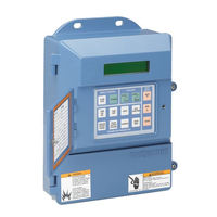
Rosemount 8712H Product Manual (112 pages)
Magnetic Flowmeter Transmitter
Brand: Rosemount
|
Category: Transmitter
|
Size: 3.18 MB
Table of Contents
-
Table of Contents
5
-
Section 1
9
-
Introduction
9
-
Manual Scope
9
-
SECTION 1 Manual Scope
9
-
System Description
10
-
-
Section 2
11
-
Installation
11
-
Introduction
11
-
Safety Messages
11
-
SECTION 2 Introduction
11
-
Transmitter Symbols
11
-
Pre-Installation
12
-
Mechanical Considerations
12
-
Environmental Considerations
13
-
-
Installation Procedures
13
-
Mount the Transmitter
13
-
Identify Options and Configurations
13
-
Hardware Jumpers/Switches
14
-
Electrical Considerations
15
-
Conduit Connections
16
-
Conduit Installation
16
-
-
Options, Considerations, and Procedures
19
-
Connect Transmitter Power
19
-
Connect 4-20 Ma Loop External Power Source
20
-
Connect Pulse Output Power Source
21
-
Connect Auxiliary Output Control
22
-
Connect Positive Zero Return (PZR) Power Source
23
-
-
Flowtube Connections
24
-
Rosemount Flowtubes
24
-
Flowtubes of Other Manufacturers
24
-
-
Applying Power
25
-
Software Installation
25
-
Installation Check and Guide
26
-
-
-
Section 3
29
-
Basic Features
29
-
Data Entry
30
-
Selecting Options
30
-
-
-
Local Operator
29
-
Local Operator Interface
29
-
LOI Examples
30
-
Select Value Example
30
-
-
Diagnostic Messages
32
-
-
Interface
29
-
Section 4
33
-
Device Software Functions
33
-
Introduction
33
-
Safety Messages
33
-
SECTION 4 Introduction
33
-
Process Variables
34
-
Diagnostics and Service
35
-
Analog Output Test
35
-
Pulse Output Test
35
-
Self Test
35
-
D/A Trim and (4-20 Ma Output Trim)
35
-
Scaled D/A Trim
36
-
Electronics Trim
36
-
Auto Zero Trim
37
-
Universal Auto Trim (Model 8712U Only)
37
-
-
Basic Setup
38
-
Tag
38
-
Flow Rate Units
38
-
URV (Upper Range Value)
38
-
LRV (Lower Range Value)
39
-
Line Size
39
-
Calibration Number
40
-
Damping
40
-
-
Detailed Setup
41
-
Pulse Output Scaling
41
-
Pulse Width
42
-
Special Units
43
-
User-Defined Volume Unit
43
-
Base Volume Unit
43
-
Conversion Number
44
-
Base Time Unit
44
-
User-Defined Flow Unit
44
-
Auxiliary Output
44
-
Totalizer
44
-
Measure Gross Total
45
-
Start Totalizer
45
-
Stop Totalizer
45
-
Reset Totalizer
45
-
Low Flow Cutoff
45
-
Coil Drive Frequency
45
-
Control Status
46
-
Signal Processing Control
46
-
Number of Samples
46
-
Maximum Percent Limit
47
-
Time Limit
47
-
-
Review Variables
47
-
Review
47
-
-
Miscellaneous Functions
48
-
Coil Current (Model 8712U Only)
48
-
Transmitter Gain (Model 8712U Only)
48
-
Flowtube Gain (Model 8712U Only)
48
-
Message
48
-
Date
48
-
Flowtube Tag
48
-
Flowtube Serial Number
48
-
Liner Material
49
-
Electrode Type
49
-
Electrode Material
49
-
-
Multidrop Communications
50
-
SECTION 5 Safety Messages
51
-
Basic Transmitter Troubleshooting
52
-
Advanced Transmitter Troubleshooting
53
-
Software Testing
55
-
Process Noise
57
-
Replacing the LOI Electronics
59
-
-
Return of Materials
60
-
SECTION 6 Specifications
61
-
Performance Specifications
63
-
Physical Specifications
64
-
-
Ordering Information
66
-
Spare Parts
67
-
Standard Configuration
68
-
-
APPENDIX A Introduction
69
-
Basic Features
73
-
Action Keys
74
-
HART Fast Key Feature
75
-
-
Menus and Functions
76
-
Diagnostic Messages
77
-
-
Appendix B
79
-
APPENDIX B Wiring Diagrams
79
-
Model 8712C/U Transmitter
80
-
High-Signal Transmitter
81
-
Model 8701 Flowtube to Model 8712U Transmitter
82
-
Model 8705 Flowtube to Model 8712U Transmitter
83
-
Model 8711 Flowtube to Model 8712U Transmitter
84
-
Brooks Flowtubes
85
-
Model 7400 Flowtube to Model 8712U Transmitter
86
-
-
Endress and Hauser Flowtubes
87
-
Fischer and Porter Flowtubes
88
-
Model 10D1418 Flowtube to Model 8712U Transmitter
88
-
Model 10D1419 Flowtube to Model 8712U Transmitter
89
-
Model 10D1430 Flowtube (Remote) to Model 8712U Transmitter
90
-
Model 10D1430 Flowtube (Integral) to Model 8712U Transmitter
91
-
Model 10D1465 and Model 10D1475 Flowtubes (Integral) to Model 8712U Transmitter
92
-
Fischer and Porter Flowtube to Model 8712U Transmitter
93
-
-
Foxboro Flowtubes
94
-
Series 1800 Flowtube to Model 8712U Transmitter
94
-
Series 1800 (Version 2) Flowtube to Model 8712U Transmitter
95
-
Series 2800 Flowtube to Model 8712U Transmitter
96
-
Foxboro Flowtube to Model 8712U Transmitter
97
-
-
Kent Veriflux VTC Flowtube
98
-
Veriflux VTC Flowtube to Model 8712U Transmitter
98
-
-
Kent Flowtubes
99
-
Kent Flowtube to Model 8712U Transmitter
99
-
-
Krohne Flowtubes
100
-
Krohne Flowtube to Model 8712U Transmitter
100
-
-
Taylor Flowtubes
101
-
Series 1100 Flowtube to Model 8712U Transmitter
101
-
Taylor Flowtube to Model 8712U Transmitter
102
-
-
Yamatake Honeywell Flowtubes
103
-
Yamatake Honeywell Flowtube to Model 8712U Transmitter
103
-
-
Yokogawa Flowtubes
104
-
Yokogawa Flowtube to Model 8712U Transmitter
104
-
-
Generic Manufacturer Flowtubes
105
-
Generic Manufacturer Flowtube to Model 8712U Transmitter
105
-
Identify the Terminals
105
-
Wiring Connections
105
-
-
Advertisement
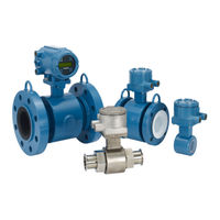
Rosemount 8712H Quick Install Manual (28 pages)
8700 series.
Magnetic Flowmeter
Sensor
Brand: Rosemount
|
Category: Measuring Instruments
|
Size: 3.87 MB
Table of Contents
-
Return Policy
4
-
Emerson Flow Customer Service
5
-
Location and Position
6
-
Environmental Considerations
6
-
Flow Direction
6
-
Electrode Orientation
9
-
Sensor Installation
10
-
Flanged Sensors
10
-
Wafer Sensors
14
-
Process Reference Connection
19
-
Wiring Sensor to Transmitter
22
Advertisement
Related Products
-
Rosemount 848T
-
Rosemount 8712C
-
Rosemount 8712U
-
Rosemount 8732E
-
Rosemount 8712
-
Rosemount 8712D Series
-
Rosemount 8712EM
-
Rosemount 8712E
-
Rosemount Series 8700
-
Rosemount 8750WA
Rosemount Categories
Measuring Instruments
Transmitter
Accessories
Analytical Instruments
Touch Panel
More Rosemount Manuals
-
Page 1
Reference Manual 00809-0100-4664, Rev BA January 2010 Rosemount 8712 Remote Mount Magnetic Flowmeter System www.rosemount.com… -
Page 3
The products described in this document are NOT designed for nuclear-qualified applications. Using non-nuclear qualified products in applications that require nuclear-qualified hardware or products may cause inaccurate readings. For information on Rosemount nuclear-qualified products, contact your local Emerson Process Management Sales Representative. www.rosemount.com… -
Page 5: Table Of Contents
Connections ……..2-13 Rosemount Sensors ……..2-13 Transmitter to Sensor Wiring.
-
Page 6
Reference Manual 00809-0100-4664, Rev BA Rosemount 8732 January 2010 Basic Setup……….3-8 Tag . -
Page 7
Diagnostics Licensing the 8712 Diagnostics……C-2 Tunable Empty Pipe Detection ……C-2 Tunable Empty Pipe Parameters. -
Page 8
Rosemount Sensors …….. -
Page 9: System Description
The transmitter can be integrally or remotely mounted from the sensor. This manual is designed to assist in the installation and operation of the Rosemount 8712 Magnetic Flowmeter Transmitter and the Rosemount 8700 Series Magnetic Flowmeter Sensors. www.rosemount.com…
-
Page 10: Safety Messages
Attempting to install and operate the Rosemount 8705, Rosemount 8707 High-Signal, Rosemount 8711, or Rosemount 8721 Magnetic Sensors with the Rosemount 8712 or Rosemount 8732 Magnetic Flowmeter Transmitter without reviewing the instructions contained in this manual could result in personal injury or equipment damage.
-
Page 11: Safety Messages
Verify that the operating environment of the sensor and transmitter is consistent with the appropriate hazardous area approval. Do not connect a Rosemount 8712 to a non-Rosemount sensor that is located in an explosive atmosphere. www.rosemount.com…
-
Page 12: Transmitter Symbols
Installation of this transmitter in an explosive environment must be in accordance with the appropriate local, national, and international standards, codes, and practices. Please review the approvals section of the 8712 reference manual for any restrictions associated with a safe installation.
-
Page 13
Reference Manual 00809-0100-4664, Rev BA Rosemount 8712 January 2010 Figure 2-1. Rosemount 8712 Dimensional Drawing WITH STANDARD COVER 4.31 9.01 (109) (229) 0.44 2.81 3.11 (11) (71) (79) 12.02 (305) 11.15 (283) 2.96 (75) WITH LOI COVER –14 NPT Conduit… -
Page 14: Environmental Considerations
Attach the 8712 to the mounting location using the mounting screws. Identify Options and The standard application of the 8712 includes a 4–20 mA output and control of the sensor coils. Other applications may require one or more of the…
-
Page 15
Connect 4–20 mA Loop External Power Source on page 2-9. Transmitter Security The security switch on the 8712 allows the user to lock out any configuration changes attempted on the transmitter. No changes to the configuration are allowed when the switch is in the ON position. The flow rate indication and totalizer functions remain active at all times. -
Page 16: Conduit Ports And Connections
AC or DC power wiring. • Device must be properly grounded or earthed according to local electric codes. • Rosemount combination cable model number 08712-0752-0001 (ft) or 08712-0752-0003 (m) is required to be used to meet EMC requirements.
-
Page 17: Electrical Considerations
Transmitter Input Power The 8712 transmitter is designed to be powered by 90-250 V AC, 50–60 Hz or 12–42 V DC. The eight digit in the transmitter model number designates the appropriate power supply requirement.
-
Page 18
Reference Manual 00809-0100-4664, Rev BA Rosemount 8712 January 2010 Table 2-1. Length of Annealed Copper (cu) Wires Types of Power Maximum Length of the Wire for Each Supply Wires Corresponding Power Supply Source Wire Annealed Cu 42 V DC 30 V DC 20 V DC 12.5 V DC… -
Page 19: Installation Category
3 Amp, Quick Acting Bussman AGC3 or Equivalent OPTIONS, If the application of the 8712 includes the use of options such as multidrop communications, auxiliary output control, or pulse output, certain CONSIDERATIONS, AND requirements may apply in addition to those previously listed. Be prepared to…
-
Page 20: Connect Pulse Output Power Source
Reference Manual 00809-0100-4664, Rev BA Rosemount 8712 January 2010 Internal The 4–20 mA analog power loop may be powered from the transmitter itself. Resistance in the loop must be 1,000 ohms or less. If a Handheld Communicator or control system will be used, it must be connected across a minimum of 250 ohms resistance in the loop.
-
Page 21: Connect Auxiliary Channel 1
Reference Manual 00809-0100-4664, Rev BA Rosemount 8712 January 2010 The pulse output option requires an external power source. Complete the following steps to connect an external power supply. Ensure that the power source and connecting cable meet the requirements outlined previously.
-
Page 22: Connect Auxiliary Channel 2
Reference Manual 00809-0100-4664, Rev BA Rosemount 8712 January 2010 When configured as an output, the following requirements apply: Supply Voltage: 5 to 28V DC Maximum Power: 2 watts Switch Closure: optically isolated solid state switch When using channel 1 as a digital output, the power source must be connected to the transmitter.
-
Page 23: Sensor Connections
This section covers the steps required to physically install the transmitter including wiring and calibration. Rosemount Sensors To connect the transmitter to a non-Rosemount sensor, refer to the appropriate wiring diagram in Appendix D: Wiring Diagrams. The calibration procedure listed is not required for use with Rosemount sensors.
-
Page 24: Conduit Cables
For remote mount installations, combination signal and coil drive cable should be limited to less than 300 ft. (100 m). Rosemount recommends using the combination signal and coil drive for N5, E5 approved sensors for optimum performance.
-
Page 25: Sensor To Remote Mount Transmitter Connections
Connect coil drive and electrode cables as shown in Figure 2-13. Transmitter Connections Do not connect AC power to the sensor or to terminals 1 and 2 of the transmitter, or replacement of the electronics board will be necessary. Figure 2-13. Wiring Diagram Rosemount 8712 Transmitter Rosemount 8705/8707/8711/8721 sensors 2-15…
-
Page 26: Rev Ba Rosemount
Reference Manual 00809-0100-4664, Rev BA Rosemount 8712 January 2010 2-16…
-
Page 27: Introduction
“Universal Sensor Wiring Diagrams” on page E-1. The Rosemount 8712 features a full range of software functions for configuration of output from the transmitter. Software functions are accessed through the LOI, AMS, a Handheld Communicator, or a control system.
-
Page 28: Local Operator Interface
Refer to Section 6 «Maintenance and Troubleshooting» for further information. LOCAL OPERATOR The optional Local Operator Interface (LOI) provides an operator communications center for the 8712. By using the LOI, the operator can INTERFACE access any transmitter function for changing configuration parameter settings, checking totalized values, or other functions.
-
Page 29: Basic Features
Transmitter Parameter Keys The transmitter parameter keys provide direct access to the most common transmitter parameters and stepped access to the advanced functions of the 8712 through the AUX. FUNCTION key. Figure 3-1. Local Operator Interface Keypad DATA…
-
Page 30: Selecting Options
Reference Manual 00809-0100-4664, Rev BA Rosemount 8712 January 2010 Selecting Options To select pre-defined software options on the LOI, use the following procedure: Access the appropriate option. Use SHIFT or INCR. to toggle between the applicable choices. Press ENTER when the desired choice is displayed on the screen.
-
Page 31
Function Performed Keys Tube Cal No. Identifies the calibration number when using Rosemount sensors, or other manufacturers’ sensors calibrated at the Rosemount factory Tube Size Specifies the sensor size and identifies the corresponding maximum flow (0.1 — through 80-inch line sizes) -
Page 32: Diagnostic Messages
• Totalizer indicator (A flashing letter “T” on the LOI indicates to totalizer is activated) Review The 8712 includes a capability that enables you to review the configuration variable settings. Fast Keys 1, 5 The flowmeter configuration parameters set at the factory should be reviewed to ensure accuracy and compatibility with your particular application of the flowmeter.
-
Page 33: Pv — Primary Variable
Reference Manual 00809-0100-4664, Rev BA Rosemount 8712 January 2010 PV — Primary Variable The Primary Variable shows the current measured flow rate. This value determines the analog output from the transmitter. Fast Keys 1, 1, 1 LOI Key FLOW RATE…
-
Page 34: Pulse Output
The Pulse Output displays the current value of the pulse signal. Fast Keys 1, 1, 5 BASIC SETUP The basic configuration functions of the Rosemount 8712 must be set for all applications of the transmitter in a magnetic flowmeter system. If your Fast Keys 1, 3 application requires the advanced functionality features of the Rosemount 8712, see Section 4 «Operation»…
-
Page 35
(see “Flow Units” on page 3-8). If your application has special needs and the standard configurations do not apply, the Rosemount 8712 provides the flexibility to configure the transmitter in a custom-designed units format using the special units variable. -
Page 36: Line Size
The actual special units setting you define will not appear. Four characters are available to store the new units designation. The 8712 LOI will display the four character designation as configured.
-
Page 37: Pv Urv (Upper Range Value)
Reference Manual 00809-0100-4664, Rev BA Rosemount 8712 January 2010 PV URV The upper range value (URV), or analog output range, is preset to 30 ft/s at the factory. The units that appear will be the same as those selected under the (Upper Range Value) units parameter.
-
Page 38: Calibration Number
Rosemount flow lab, accuracy of the system may be compromised. If your sensor is not a Rosemount sensor and was not calibrated at the Rosemount factory, contact your Rosemount representative for assistance. If your sensor is imprinted with an eight-digit number or a k-factor, check in the sensor wiring compartment for the sixteen-digit calibration number.
-
Page 39: Introduction
This section contains information for advanced configuration parameters and diagnostics. The software configuration settings for the Rosemount 8712 can be accessed through a HART-based communicator, Local Operator Interface (LOI), or through a control system. The software functions for the Field Communicator are described in detail in this section of the manual.
-
Page 40: Basic Diagnostics
For more details on the electronics temperature diagnostic, see Appendix C: «Diagnostics». Basic Diagnostics The basic diagnostics menu contains all of the standard diagnostics and tests that are available in the 8712 transmitter. Field Comm. 1, 2, 2 Self Test Field Comm.
-
Page 41
1, 2, 2, 2, 3 Send the analog output into an alarm mA value. Actual mA value depends on the alarm configuration. • Rosemount Standard High Alarm – 22.6 mA • Rosemount Standard Low Alarm – 3.75 mA • Namur Compliant High Alarm – 22.6 mA •… -
Page 42
Reference Manual 00809-0100-4664, Rev BA Rosemount 8712 January 2010 Empty Pipe Trigger Level Field Comm. 1, 2, 2, 4, 2 LOI Key AUX. FUNCTION Limits: 3 to 2000 Configure the threshold limit that the empty pipe value must exceed before the diagnostic alert activates. -
Page 43
Reference Manual 00809-0100-4664, Rev BA Rosemount 8712 January 2010 In Range – The HART Alert will activate when the measured flow rate is between the High Limit 1 and Low Limit 1 set points. Out of Range – The HART Alert will activate when the measured flow rate exceeds the High Limit 1 set point or falls below the Low Limit 1 set point. -
Page 44
Reference Manual 00809-0100-4664, Rev BA Rosemount 8712 January 2010 High Limit 2 Field Comm. 1, 2, 2, 7, 3 Set the flow rate value that corresponds to the high limit set point for the Flow Limit 2 alert. If a digital output is configured for Flow Limit 1, the digital output will activate when the conditions for mode 1 are met. -
Page 45: Advanced Diagnostics
Alert status. Advanced Diagnostics The advanced diagnostics menu contains information on all of the additional diagnostics and tests that are available in the 8712 transmitter if one of the Field Comm. 1, 2, 3 diagnostics suite packages was ordered.
-
Page 46
Reference Manual 00809-0100-4664, Rev BA Rosemount 8712 January 2010 8714i Results Field Comm. 1, 2, 3, 1, 2 LOI Key XMTR INFO Review the results of the most recently performed 8714i Meter Verification test. Information in this section details the measurements taken and if the meter passed the verification test. -
Page 47
Have the transmitter measure and store the sensor signature values. These values will then be used as the baseline for the meter verification test. Use this when connecting to older Rosemount or another manufacturers sensors, or installing the magnetic flowmeter system for the first time. For more details… -
Page 48
Reference Manual 00809-0100-4664, Rev BA Rosemount 8712 January 2010 Recall Last Saved Values Field Comm. 1, 2, 3, 1, 3, 3 LOI Key AUX. FUNCTION Recalls the last saved “good” values for the sensor signature. Set Pass/Fail Criteria Field Comm. -
Page 49
Reference Manual 00809-0100-4664, Rev BA Rosemount 8712 January 2010 Coil Signature Field Comm. 1, 2, 3, 1, 5, 2 View the measured value for the coil signature taken during the 8714i meter verification test. Electrode Resistance Field Comm. 1, 2, 3, 1, 5, 3 View the measured value for the electrode resistance taken during the 8714i meter verification test. -
Page 50: Diagnostic Variable Values
Reference Manual 00809-0100-4664, Rev BA Rosemount 8712 January 2010 Diagnostic Variable From this menu, all of the diagnostic variable values can be reviewed. This information can be used to get more information about the transmitter, sensor, Values and process, or to get more detail about an alert that may have activated.
-
Page 51
Reference Manual 00809-0100-4664, Rev BA Rosemount 8712 January 2010 8714i Test Result Field Comm. 1, 2, 3, 7, 3 Displays the results of the 8714i Meter Verification test as pass or fail. For more details on this parameter see Appendix C: «Diagnostics». -
Page 52: Trims
Digital trim is the function by which the factory calibrates the transmitter. This procedure is rarely needed by users. It is only necessary if you suspect the Rosemount 8712 is no longer accurate. A Rosemount 8714D Calibration Standard is required to complete a digital trim. Attempting a digital trim without a Rosemount 8714D Calibration Standard may result in an inaccurate transmitter or an error message.
-
Page 53
“DIGITAL TRIM FAILURE” message may appear. If this message occurs, no values were changed in the transmitter. Simply power down the Rosemount 8712 to clear the message. To simulate a nominal sensor with the Rosemount 8714D Calibration… -
Page 54: Status
LOI Key XMTR INFO ADVANCED In addition to the basic configuration options and the diagnostic information and controls, the 8712 has many advanced functions that can also be CONFIGURATION configured as required by the application. DETAILED SETUP The detailed setup function provides access to other parameters within the transmitter that can be configured such as coil drive frequency, output Field Comm.
-
Page 55: Configure Outputs
Reference Manual 00809-0100-4664, Rev BA Rosemount 8712 January 2010 Density Value Field Comm. 1, 4, 1, 2 LOI Key AUX. FUNCTION The density value is used to convert from a volumetric flow rate to a mass flow rate using the following equation:…
-
Page 56
Field Comm. 1, 4, 2, 1, 4 The analog output alarm type displays the alarm mode the 8712 is currently set for. This value is set by a switch on the electronics board. There are two available options for this setting: •… -
Page 57
Reference Manual 00809-0100-4664, Rev BA Rosemount 8712 January 2010 Loop Test Field Comm. 1, 4, 2, 1, 5 LOI Key AUX. FUNCTION The loop test allows you to drive the transmitter output to a desired electrical current output on terminals 1 and 2. This capability allows you to check the entire current loop prior to start-up. -
Page 58
10,000 Hz. With the 110 percent overrange capability, the absolute limit is 11,000 Hz. For example, if you want the Rosemount 8712 to pulse every time 0.01 gallons pass through the sensor, and the flow rate is 10,000 gal/min, you will exceed the 10,000 Hz full-scale limit: … -
Page 59
Reference Manual 00809-0100-4664, Rev BA Rosemount 8712 January 2010 The best choice for this parameter depends upon the required resolution, the number of digits in the totalizer, the extent of range required, and the maximum counter external frequency. NOTE For totalizing on the LOI, ten digits are available. -
Page 60
Reference Manual 00809-0100-4664, Rev BA Rosemount 8712 January 2010 Example The maximum flow rate is 10,000 gpm. Set the pulse output scaling such that the transmitter outputs 10,000 Hz at 10,000 gpm. Flow Rate (gpm) Pulse Scaling ———————————————————- — (60 s/min)(Frequency) -
Page 61
AUX. FUNCTION This menu is used to configure the optional digital input and digital output parameters of the 8712 transmitter. Note that this configuration option is only active if the auxiliary output suite (option code AX) was ordered or licensed in the field. -
Page 62
Reference Manual 00809-0100-4664, Rev BA Rosemount 8712 January 2010 DIO 1 Control Field Comm. 1, 4, 2, 3, 1, 2 Displays the configuration for Channel 1 as either a discrete Input or Output. Digital Input 1 Field Comm. 1, 4, 2, 3, 1, 3 Displays what digital input Channel 1 will be set to when the Control for Channel 1 is set to Input. -
Page 63
Reference Manual 00809-0100-4664, Rev BA Rosemount 8712 January 2010 Control 1 Field Comm. 1, 4, 2, 3, 3, 1 Turns the Flow Limit 1 HART Alert ON or OFF. ON – The transmitter will generate a HART alert when the defined conditions are met. -
Page 64
Reference Manual 00809-0100-4664, Rev BA Rosemount 8712 January 2010 ON – The transmitter will generate a HART alert when the defined conditions are met. If a digital output is configured for Flow Limit 1, the digital output will activate when the conditions for mode 1 are met. -
Page 65
Reference Manual 00809-0100-4664, Rev BA Rosemount 8712 January 2010 Total Mode Field Comm. 1, 4, 2, 3, 5, 2 Mode that determines when the Total Limit HART Alert will activate. > High Limit – The HART Alert will activate when the measured net total exceeds the Total High Limit set point. -
Page 66
Reference Manual 00809-0100-4664, Rev BA Rosemount 8712 January 2010 Totalizer Units Field Comm. 1, 4, 2, 5, 1 LOI Key AUX. FUNCTION Totalizer units allow for the configuration of the units that the totalized value will be displayed as. These units are independent of the flow units. -
Page 67
The alarm level allows you to drive the transmitter to preset values if an alarm occurs. There are two options: • Rosemount Alarm and Saturation Values • NAMUR-Complaint Alarm and Saturation Levels Table 4-3. Rosemount (Standard) Alarm and Saturation Values Level 4-20 mA Saturation 4-20 mA Alarm 3.75 mA 3.9 mA 22.6 mA… -
Page 68
Rosemount 8712 in the loop. NOTE The Rosemount 8712 is set to poll address zero at the factory, allowing it to operate in the standard point-to-point manner with a 4–20 mA output signal. To activate multidrop communication, the transmitter poll address must be changed to a number between 1 and 15. -
Page 69: Loi Configuration
Forward Total and Reverse Total • Net Total and Gross Total Signal Processing The 8712 contains several advanced functions that can be used to stabilize erratic outputs caused by process noise. The signal processing menu Field Comm. 1, 4, 4 LOI Key AUX.
-
Page 70
Field Comm. 1, 4, 4, 2, 1 When ON is selected, the Rosemount 8712 output is derived using a running average of the individual flow inputs. Signal processing is a software algorithm that examines the quality of the electrode signal against user-specified tolerances. -
Page 71
10 seconds. In some cases this may be unacceptable. By setting the time limit, you can force the 8712 to clear the value of the running average and re-establish the output and average at the new flow rate once the time limit has elapsed. -
Page 72: Universal Auto Trim
00809-0100-4664, Rev BA Rosemount 8712 January 2010 Universal Auto Trim The universal auto trim function enables the Rosemount 8712 to calibrate sensors that were not calibrated at the Rosemount factory. The function is Field Comm. 1, 4, 5 LOI Key AUX.
-
Page 73
Revisions numbers are fixed informational variables that provide the revision number for different elements of your Field Communicator and Rosemount 8712. These revision numbers may be required when calling the factory for support. Revision numbers can only be changed at the factory and are… -
Page 74
Reference Manual 00809-0100-4664, Rev BA Rosemount 8712 January 2010 Software Revision Number Field Comm. 1, 4, 6, 10, 3 This function displays the software revision number of the transmitter. This is one piece of information required to generate a license code to enable diagnostics in the field. -
Page 75
Reference Manual 00809-0100-4664, Rev BA Rosemount 8712 January 2010 Flange Material Field Comm. 1, 4, 6, 11, 2 LOI Key XMTR INFO Flange material enables you to select the flange material for your magnetic transmitter system. This variable only needs to be changed if you have changed your sensor. -
Page 76
Reference Manual 00809-0100-4664, Rev BA Rosemount 8712 January 2010 Liner Material Field Comm. 1, 4, 6, 11, 5 LOI Key XMTR INFO Liner material enables you to select the liner material for the attached sensor. This variable only needs to be changed if you have replaced your sensor. -
Page 77
Reference Manual 00809-0100-4664, Rev BA Rosemount 8712 January 2010 Figure 4-2. Field Communicator Menu Tree for the Rosemount 8712 4-39… -
Page 78
Reference Manual 00809-0100-4664, Rev BA Rosemount 8712 January 2010 Figure 4-3. HART Fast Key Function HART Fast Keys Process Variables (PV) Primary Variable Value 1,1,1 Primary Variable % 1,1,2 PV Loop Current 1,1,3 Totalizer Set-Up 1,1,4 Totalizer Units 1,1,4,1 Gross Total… -
Page 79
Reference Manual 00809-0100-4664, Rev BA Rosemount 8712 January 2010 Function HART Fast Keys Sensor Cal Test Result 1,2,3,1,2,9 Coil Circuit Test Result 1,2,3,1,2,x Electrode Circuit Test Result 1,2,3,1,2,x Sensor Signature 1,2,3,1,3 Signature Values 1,2,3,1,3,1 Coil Resistance 1,2,3,1,3,1,1 Coil Signature 1,2,3,1,3,1,2… -
Page 80
Reference Manual 00809-0100-4664, Rev BA Rosemount 8712 January 2010 Function HART Fast Keys Base Volume Unit 1,3,2,2,2 Conversion Number 1,3,2,2,3 Base Time Unit 1,3,2,2,4 Flow Rate Unit 1,3,2,2,5 Line Size 1,3,3 PV URV 1,3,4 PV LRV 1,3,5 Calibration Number 1,3,6… -
Page 81
Reference Manual 00809-0100-4664, Rev BA Rosemount 8712 January 2010 Function HART Fast Keys Diagnostic Status Alert 1,4,2,3,6 Reverse Flow 1,4,2,4 Totalizer Setup 1,4,2,5 Totalizer Units 1,4,2,5,1 Gross Total 1,4,2,5,2 Net Total 1,4,2,5,5 Reverse Total 1,4,2,5,4 Start Totalizer 1,4,2,5,5 Stop Totalizer… -
Page 82
Function Performed Keys Tube Cal No. Identifies the calibration number when using Rosemount sensors, or other manufacturers’ sensors calibrated at the Rosemount factory Tube Size Specifies the sensor size and identifies the corresponding maximum flow (0.1 — through 80-inch line sizes) -
Page 83
Reference Manual 00809-0100-4664, Rev BA Rosemount 8712 January 2010 Auxiliary Functions Function Options Run 8714i Runs the meter verification diagnostic Operating Mode Normal or Filter Coil Pulse Mode 5 or 37 Hz Flow rate Display Flow–% Span, Flow–Totalize, %Span–Totalize Totalizer Display Forward–Reverse or Net–Gross… -
Page 84
Reference Manual 00809-0100-4664, Rev BA Rosemount 8712 January 2010 4-46… -
Page 85: Safety Messages
Verify that the operating environment of the sensor and transmitter is consistent with the appropriate hazardous area approval. Do not connect a Rosemount 8712 to a non-Rosemount sensor that is located in an explosive atmosphere. www.rosemount.com…
-
Page 86
Installation of this transmitter in an explosive environment must be in accordance with the appropriate local, national, and international standards, codes, and practices. Please review the approvals section of the 8712 reference manual for any restrictions associated with a safe installation. -
Page 87: Sensor Handling
Figure 5-1 shows sensors correctly supported for handling and installation. Notice the plywood end pieces are still in place to protect the sensor liner during transportation. Figure 5-1. Rosemount 8705 Sensor Support for Handling 6-Inch and Larger ½- through 4-Inch…
-
Page 88: Sensor Mounting
Reference Manual 00809-0100-4664, Rev BA Rosemount 8712 January 2010 SENSOR MOUNTING Physical mounting of a sensor is similar to installing a typical section of pipe. Conventional tools, equipment, and accessories (bolts, gaskets, and grounding hardware) are required. Upstream/Downstream To ensure specification accuracy over widely varying process conditions,…
-
Page 89
Orientation FLOW The electrodes in the Rosemount 8711 are properly oriented when the top of the sensor is either vertical or horizontal, as shown in Figure 5-6. Avoid any mounting orientation that positions the top of the sensor at 45 degrees from… -
Page 90: Flow Direction
Reference Manual 00809-0100-4664, Rev BA Rosemount 8712 January 2010 Figure 5-6. Rosemount 8711 Mounting Position 45° Electrode Plane 45° Electrode Plane Flow Direction The sensor should be mounted so that the FORWARD end of the flow arrow, shown on the sensor identification tag, points in the direction of flow through the tube (see Figure 5-7).
-
Page 91: Installation (Flanged Sensor)
The following section should be used as a guide in the installation of the flange-type Rosemount 8705 and Rosemount 8707 High-Signal Sensors. (FLANGED SENSOR) Refer to page 5-10 for installation of the wafer-type Rosemount 8711 Sensor. Gaskets The sensor requires a gasket at each of its connections to adjacent devices or piping.
-
Page 92
All sensors require a second torquing 24 hours after initial flange bolt tightening. Table 5-1. Flange Bolt Torque Specifications for Rosemount 8705 and 8707 High-Signal Sensors PTFE/ETFE liner Polyurethane liner Class 150… -
Page 93
Reference Manual 00809-0100-4664, Rev BA Rosemount 8712 January 2010 Table 5-2. Flange Bolt Torque and Bolt Load Specifications for Rosemount 8705 PTFE/ETFE liner PN10 PN 16 PN 25 PN 40 Size Code Line Size (Newton-meter) (Newton) (Newton-meter) (Newton) (Newton-meter) (Newton) (Newton-meter) (Newton) -
Page 94: Installation (Wafer Sensor)
Reference Manual 00809-0100-4664, Rev BA Rosemount 8712 January 2010 Table 5-3. Flange Bolt Torque and Bolt Load Specifications for Rosemount 8705 Polyurethane Liner PN 10 PN 16 PN 25 PN 40 Size Code Line Size (Newton-meter) (Newton) (Newton-meter) (Newton) (Newton-meter) (Newton) (Newton-meter) (Newton)
-
Page 95: Flange Bolts
Reference Manual 00809-0100-4664, Rev BA Rosemount 8712 January 2010 Table 5-4. Stud Specifications Nominal Sensor Size Stud Specifications 0.15 – 1 inch (4 – 25 mm) 316 SST ASTM A193, Grade B8M Class 1 threaded mounted studs – 8 inch (40 – 200 mm) CS, ASTM A193, Grade B7, threaded mounting studs Place the sensor between the flanges.
-
Page 96: Installation (Sanitary Sensor)
The sensor requires a gasket at each of its connections to adjacent devices or piping. The gasket material selected must be compatible with the process fluid and operating conditions. Gaskets are supplied with all Rosemount 8721 Sanitary sensors except when the process connection is an IDF sanitary screw type.
-
Page 97
Reference Manual 00809-0100-4664, Rev BA Rosemount 8712 January 2010 NOTE Consult factory for installations requiring cathodic protection or situations where there are high currents or high potential in the process. The sensor case should always be earth grounded in accordance with national and local electrical codes. -
Page 98
Reference Manual 00809-0100-4664, Rev BA Rosemount 8712 January 2010 Figure 5-14. Grounding with Grounding Rings or Lining Protectors Grounding Rings or Lining Protectors Figure 5-15. Grounding with Grounding Rings or Lining Protectors Grounding Rings or Lining Protectors 5-14… -
Page 99: Process Leak Protection (Optional)
Figure 5-16. Grounding with Grounding Electrodes PROCESS LEAK The Rosemount 8705 and 8707 High-Signal Sensor housing is fabricated from carbon steel to perform two separate functions. First, it provides PROTECTION shielding for the sensor magnetics so that external disturbances cannot (OPTIONAL) interfere with the magnetic field and thus affect the flow measurement.
-
Page 100: Relief Valves
Reference Manual 00809-0100-4664, Rev BA Rosemount 8712 January 2010 Figure 5-17. Standard Housing Configuration — Sealed Welded Housing (Option Code W0) –14 NPT Conduit Connection (no relief valve) Relief Valves The first optional configuration, identified by the W1 in the model number option code, uses a completely welded coil housing.
-
Page 101: Process Leak Containment
Reference Manual 00809-0100-4664, Rev BA Rosemount 8712 January 2010 Process Leak The second optional configuration, identified as option code W3 in the model number, divides the coil housing into three compartments: one for each Containment electrode and one for the coils. Should a damaged liner or electrode fault allow process fluid to migrate behind the electrode seals, the fluid is contained in the electrode compartment.
-
Page 102
Reference Manual 00809-0100-4664, Rev BA Rosemount 8712 January 2010 5-18… -
Page 103: Safety Information
FM or CSA approval. Do not connect a Rosemount 8712 to a non-Rosemount sensor that is located in an explosive atmosphere. Mishandling products exposed to a hazardous substance may result in death or serious injury.
-
Page 104: Installation Check And Guide
Reference Manual 00809-0100-4664, Rev BA Rosemount 8712 January 2010 INSTALLATION CHECK Use this guide to check new installations of Rosemount magnetic flowmeter systems that appear to malfunction. AND GUIDE Before You Begin Transmitter Apply power to your system before making the following transmitter checks.
-
Page 105: Diagnostic Messages
Problems in the magnetic flowmeter system are usually indicated by incorrect output readings from the system, error messages, or failed tests. Consider all MESSAGES sources in identifying a problem in your system. Table 6-1. Rosemount 8712 Basic Diagnostic Messages Message Potential Cause Corrective Action “Empty Pipe”…
-
Page 106
Calibrator is not set to 30 FPS Change calibrator setting to 30 FPS Bad calibrator Replace calibrator Table 6-2. Rosemount 8712 Advanced Diagnostic Messages (Suite 1 — Option Code DA1) Message Potential Cause Corrective Action Grounding/Wiring Fault Improper installation of wiring See “Sensor to Remote Mount Transmitter Connections”… -
Page 107
Reference Manual 00809-0100-4664, Rev BA Rosemount 8712 January 2010 Table 6-4. Basic Troubleshooting–Rosemount 8712 Symptom Potential Cause Corrective Action Output at 0 mA No power to transmitter Check power source and connections to the transmitter Blown fuse Check the fuse and replace with an appropriately rated fuse, if necessary… -
Page 108: Transmitter Troubleshooting
Reference Manual 00809-0100-4664, Rev BA Rosemount 8712 January 2010 TRANSMITTER TROUBLESHOOTING Table 6-5. Advanced Troubleshooting–Rosemount 8712 Symptom Potential Cause Corrective Action Does not appear to be within Transmitter, control system, or other Check all configuration variables for the transmitter, sensor,…
-
Page 109
Sensor calibration number Units Line size Electrode coating Use bulletnose electrodes in the Rosemount 8705 Sensor. Downsize the sensor to increase the flow rate above 3 ft/s. Periodically clean the sensor Air in line Move the sensor to another location in the process line to… -
Page 110: Quick Troubleshooting
To interpret the results, the hazardous location certification for the sensor must be known. Applicable codes for the Rosemount 8705 are N0, N5, and KD. Applicable codes for the Rosemount 8707 are N0 and N5. Applicable codes for the Rosemount 8711 are N0, N5, E5, and CD.
-
Page 111
Reference Manual 00809-0100-4664, Rev BA Rosemount 8712 January 2010 Table 6-6. Sensor Test Sensor Required Measuring at Test Location Equipment Connections Expected Value Potential Cause Corrective Action A. Sensor Installed or Multimeter 1 and 2 = R 2… -
Page 112: Step 4: Uninstalled Sensor Tests
Sensor Tests be known. Applicable codes for the Rosemount 8705 are N0, N5, and KD. Applicable codes for the Rosemount 8707 are N0 and N5. Applicable codes for the Rosemount 8711 are N0, N5, E5, and CD.
-
Page 113
Measure both electrodes. One electrode should result in an open reading, while the other electrode should be less than 275 Table 6-8. Uninstalled Rosemount 8711 Wafer Sensor Tests Hazardous Location Certification Measuring at Connections N5, E5, CD 18 and Electrode … -
Page 114
Reference Manual 00809-0100-4664, Rev BA Rosemount 8712 January 2010 6-12… -
Page 115: Functional Specifications
Physical Specifications ……page A-8 Rosemount 8712E Ordering Information … . . page A-9…
-
Page 116
Reference Manual 00809-0100-4664, Rev BA Rosemount 8712 January 2010 DC Load Limitations (Analog Output) Maximum loop resistance is determined by the voltage level of the external power supply, as described by: FIGURE 1. DC Load Limitations 1250 1000 Operating Region 10.8… -
Page 117
Reference Manual 00809-0100-4664, Rev BA Rosemount 8712 January 2010 Humidity Limits 0–100% RH to 120 °F (49 °C), decreases linearly to 10% RH at 130 °F (54 °C) Enclosure Rating Type 4X, IP66 Output Signals Analog Output Adjustment 4–20 mA, switch-selectable as internally or externally powered 5 to 24 V DC;… -
Page 118
Reference Manual 00809-0100-4664, Rev BA Rosemount 8712 January 2010 Flow Limits (2): Activates switch closure output when the transmitter measures a flow rate that meets the conditions established for this alert. There are two independent flow limit alerts that can be configured as discrete outputs. -
Page 119
Damping Adjustable between 0.0 and 256 seconds Sensor Compensation Rosemount sensors are flow-calibrated and assigned a calibration factor at the factory. The calibration factor is entered into the transmitter, enabling interchangeability of sensors without calculations or a compromise in accuracy. -
Page 120: Performance Specifications
Includes the combined effects of linearity, hysteresis, repeatability, and calibration uncertainty. Rosemount 8712E with 8705/8707 Sensor: Standard system accuracy is ±0.25% of rate ±1.0 mm/sec from 0.04 to 6 ft/s (0.01 to 2 m/s); above 6 ft/s (2 m/s), the system has an accuracy of ±0.25% of rate ±1.5 mm/sec.
-
Page 121
0.04 and 3.0 ft/s (0.01 and 1 m/s), the system has an accuracy of ±0.015 ft/s (0.005 m/s). Rosemount 8712E with Other Manufacturers’ Sensors: When calibrated in the Rosemount Flow Facility, system accuracies as good as 0.5% of rate can be attained. There is no accuracy specification for other manufacturers’ sensors calibrated in the process line. -
Page 122: Physical Specifications
Reference Manual 00809-0100-4664, Rev BA Rosemount 8712 January 2010 PHYSICAL Materials of Construction SPECIFICATIONS Housing Low-copper aluminum, Type 4X and IEC 60529 IP66 Paint Polyurethane Cover Gasket Rubber Electrical Connections Four –14 NPT connections provided on the base of the transmitter. Screw terminals provided for all of the connections.
-
Page 123: Rosemount 8712E Ordering Information
Reference Manual 00809-0100-4664, Rev BA Rosemount 8712 January 2010 ROSEMOUNT 8712E ORDERING INFORMATION Model Product Description 8712E Remote Magnetic Flowmeter Transmitter Code Transmitter Style Standard Code Transmitter Mount Remote Mount for 2 in. pipe or panel (includes CS mounting bolts and 316L SST bracket)
-
Page 124
Reference Manual 00809-0100-4664, Rev BA Rosemount 8712 January 2010 QIG Language Danish Dutch French German Finnish Italian Norwegian Portuguese Spanish Russian Swedish Typical Model Number: 8712E S R 1 A 1 N0 DA1 DA2 M4 (1) Adapter are used for this conduit entry type… -
Page 125: Product Certifications
PRODUCT CERTIFICATIONS APPROVED Rosemount Inc. — Eden Prairie, Minnesota, USA MANUFACTURING Fisher-Rosemount Technologias de Flujo, S.A. de C.V. — Chihuahua Mexico LOCATIONS Emerson Process Management Flow — Ede, The Netherlands Asia Flow Technology Center — Nanjing, China European Directive The EC declaration of conformity can be found in document number 00825-0100-4664.
-
Page 126: Sensor Approval Information
Reference Manual 00809-0100-4664, Rev BA Rosemount 8712 January 2010 Canadian Standards Association (CSA) Non-incendive for Class I, Division 2, Groups A, B, C, and D non-flammable fluids (T4 at 40 °C), and Dust-ignition proof Class II/III, Division 1, Groups E, F, and G (T4 at 40 °C) Hazardous locations;…
-
Page 127
Reference Manual 00809-0100-4664, Rev BA Rosemount 8712 January 2010 North American Certifications Factory Mutual (FM) Non-incendive for Class I, Division 2, Groups A, B, C, and D non-flammable fluids (8705/8711 T5 at 60 °C; 8707 T3C at 60 °C), and Dust-ignition proof Class II/III, Division 1, Groups E, F, and G (8705/8711 T6 at 60 °C;… -
Page 128
A fuse with a rating of maximum 0,7 A according to IEC 60127-1 shall be included in the coil excitation circuit if the sensors are used with other flow transmitters. Table B-1. Electrical Data Rosemount 8705 and 8711 Sensors Coil excitation 40 V, 0,5 A, 20 W maximum… -
Page 129
Reference Manual 00809-0100-4664, Rev BA Rosemount 8712 January 2010 Table B-3. Relation between the maximum ambient temperature, the maximum process temperature, and the temperature class Maximum Maximum process temperature °F (°C) per temperature class Ambient Temperature 0.5 in. sensor size 149°F (65°C) -
Page 130
Reference Manual 00809-0100-4664, Rev BA Rosemount 8712 January 2010 Table B-3. Relation between the maximum ambient temperature, the maximum process temperature, and the temperature class Maximum Maximum process temperature °F (°C) per temperature class Ambient Temperature 2.0 in. sensor size 149°F (65°C) -
Page 131
Reference Manual 00809-0100-4664, Rev BA Rosemount 8712 January 2010 Figure B-1. CSA Installation… -
Page 132
Reference Manual 00809-0100-4664, Rev BA Rosemount 8712 January 2010 Figure B-2. Factory Mutual Hazardous Locations… -
Page 133: Diagnostic Availability
Rosemount magmeter diagnostics can be accessed through the Local Operator Interface (LOI), the 375 Handheld Communicator, and AMS Device Manager. Access Diagnostics through the LOI for quicker installation, maintenance, and meter verification Rosemount magmeter diagnostics are available through the LOI to make maintenance of every magmeter easier. www.rosemount.com…
-
Page 134: Licensing And Enabling
ENABLING diagnostics can be licensed in the field through the use of a license key. To obtain a license key, contact your local Rosemount Representative. Each transmitter has a unique license key specific to the diagnostic option code. See the detailed procedures below for entering the license key and enabling the advanced diagnostics.
-
Page 135: Tunable Empty Pipe Parameters
Reference Manual 00809-0100-4664, Rev BA Rosemount 8712 January 2010 Tunable Empty Pipe The Tunable Empty Pipe diagnostic has one read-only parameter, and two parameters that can be custom configured to optimize the diagnostic Parameters performance. Empty Pipe Value HART Fast Keys…
-
Page 136: Troubleshooting Empty Pipe
Reference Manual 00809-0100-4664, Rev BA Rosemount 8712 January 2010 Example Set the counts to 10 Troubleshooting Empty The following actions can be taken if Empty Pipe detection is unexpected. Pipe Verify the sensor is full. Verify that the sensor has not been installed with a measurement electrode at the top of the pipe.
-
Page 137: Troubleshooting Ground/Wiring Fault
Reference Manual 00809-0100-4664, Rev BA Rosemount 8712 January 2010 Troubleshooting The transmitter detected high levels of 50/60 Hz noise caused by improper wiring or poor process grounding. Ground/Wiring Fault Verify that the transmitter is earth grounded. Connect ground rings, grounding electrode, lining protector, or grounding straps.
-
Page 138: High Process Noise Parameters
Reference Manual 00809-0100-4664, Rev BA Rosemount 8712 January 2010 High Process Noise The High Process Noise diagnostic has two read-only parameters. It does not have any configurable parameters. This diagnostic requires that flow be Parameters present in the pipe and the velocity be > 1 ft/s.
-
Page 139: High Process Noise Functionality
Rosemount High-Signal 8707 sensor be used. These sensors can be calibrated to run at lower coil drive current supplied by the standard Rosemount transmitters, but can also be upgraded by changing to the 8712H High-Signal transmitter.
-
Page 140: 8714I Meter Verification
Reference Manual 00809-0100-4664, Rev BA Rosemount 8712 January 2010 The transmitter continuously monitors signal amplitudes over a wide range of frequencies. For the high process noise diagnostic, the transmitter specifically looks at the signal amplitude at frequencies of 2.5 Hz, 7.5 Hz, 32.5 Hz, and 42.5 Hz.
-
Page 141: 8714I Meter Verification Test Parameters
Reference Manual 00809-0100-4664, Rev BA Rosemount 8712 January 2010 8714i Meter Verification The 8714i has a multitude of parameters that set the test criteria, test conditions, and scope of the calibration verification test. Test Parameters Test Conditions for the 8714i Meter Verification There are three possible test conditions that the 8714i Meter Verification test can be initiated under.
-
Page 142: 8714I Meter Verification Test Results Parameters
Reference Manual 00809-0100-4664, Rev BA Rosemount 8712 January 2010 Empty Pipe Set the test criteria for the Empty Pipe condition. The factory default for this value is set to three percent with limits configurable between one and ten percent. HART Fast Keys…
-
Page 143
Reference Manual 00809-0100-4664, Rev BA Rosemount 8712 January 2010 Viewing the 8714i Meter Verification Results Depending on the method used to view the results, they will be displayed in either a menu structure, as a method, or in the report format. When using the HART Field Communicator, each individual component can be viewed as a menu item. -
Page 144
Reference Manual 00809-0100-4664, Rev BA Rosemount 8712 January 2010 Actual Velocity Displays the velocity measured by the transmitter during the transmitter calibration verification process. HART Fast Keys 1,2,3,3,2,5 LOI Key XMTR INFO Context Menu, Device Diagnostics, 8714i Report Velocity Deviation Displays the deviation in the actual velocity compared to the simulated velocity in terms of a percentage. -
Page 145: Optimizing The 8714I Meter Verification
Reference Manual 00809-0100-4664, Rev BA Rosemount 8712 January 2010 Optimizing the 8714i The 8714i Meter Verification diagnostic can be optimized by setting the test criteria to the desired levels necessary to meet the compliance requirements Meter Verification of the application. The following examples below will provide some guidance on how to set these levels.
-
Page 146: Troubleshooting The 8714I Meter Verification Test
Reference Manual 00809-0100-4664, Rev BA Rosemount 8712 January 2010 Troubleshooting the In the event that the 8714i Meter Verification test fails, the following steps can be used to determine the appropriate course of action. Begin by reviewing the 8714i Meter Verification 8714i results to determine the specific test that failed.
-
Page 147
Reference Manual 00809-0100-4664, Rev BA Rosemount 8712 January 2010 Coil Signature The Coil Signature is a measurement of the magnetic field strength. This value is used as a baseline to determine if a sensor calibration shift has occurred when the 8714i Meter Verification diagnostic is initiated. -
Page 148: Rosemount Magnetic Flowmeter Calibration Verification Report
Reference Manual 00809-0100-4664, Rev BA Rosemount 8712 January 2010 ROSEMOUNT MAGNETIC FLOWMETER CALIBRATION VERIFICATION REPORT Calibration Verification Report Parameters Calibration Conditions: □ Internal □ External User Name: _____________________________________________ Test Conditions: □ Flowing □ No Flow, Full Pipe □ Empty Pipe…
-
Page 149: Safety Messages
Reference Manual 00809-0100-4664, Rev BA Rosemount 8712 January 2010 Appendix D Digital Signal Processing Safety Messages ……. . . page D-1 Procedures .
-
Page 150: Procedures
00809-0100-4664, Rev BA Rosemount 8712 January 2010 PROCEDURES If the output of your Rosemount 8712 is unstable, first check the wiring and grounding associated with the magnetic flowmeter system. Ensure that the following conditions are met: • Ground straps are attached to the adjacent flange or ground ring? •…
-
Page 151
Reference Manual 00809-0100-4664, Rev BA Rosemount 8712 January 2010 This software technique, known as signal processing, “qualifies” individual flow signals based on historic flow information and three user-definable parameters, plus an on/off control. These parameters are: Number of samples: The number of samples function sets the amount of time that inputs are collected and used to calculate the average value. -
Page 152
Reference Manual 00809-0100-4664, Rev BA Rosemount 8712 January 2010 Figure D-1. Signal Processing Flow Rate Limit Time Limit 12 Samples = 1 Second Time Input flow signal from sensor. Average flow signals and transmitter output, determined by the “number of samples” parameter. -
Page 153
January 2010 When Should Signal Processing Be Used? The Rosemount 8712 offers three separate functions that can be used in series for improving a noisy output. The first step is to toggle the coil drive to the 37 Hz mode and initialize with an auto zero. If the output is still noisy at this stage, signal processing should be actuated and, if necessary, tuned to match the specific application. -
Page 154
Reference Manual 00809-0100-4664, Rev BA Rosemount 8712 January 2010… -
Page 155
Diagrams Rosemount Sensors ……page E-3 ABB Sensors ……..page E-7 Brooks Sensors . -
Page 156
Reference Manual 00809-0100-4664, Rev BA Rosemount 8712 January 2010 Rosemount Transmitter Sensor Manufacturer Page Number Rosemount Rosemount 8712 Rosemount 8705, 8707, 8711, 8721 page E-3 Rosemount 8712 Rosemount 8701 page E-4 Brooks Rosemount 8712 Model 5000 page E-9 Rosemount 8712… -
Page 157: Rosemount Sensors
ROSEMOUNT SENSORS Rosemount Connect coil drive and electrode cables as shown in Figure E-1. 8705/8707/8711/8721 Sensors to Rosemount 8712 Transmitter Figure E-1. Wiring Diagram to a Rosemount 8712 Transmitter ROSEMOUNT 8712 TRANSMITTER 8705/8707/8711/8721 SENSORS Table E-1. Rosemount 8705/8707/8711/8721 Sensor Rosemount 8712 Transmitters…
-
Page 158
00809-0100-4664, Rev BA Rosemount 8712 January 2010 Rosemount 8701 Sensor Connect coil drive and electrode cables as shown in Figure E-2 on page E-4. to Rosemount 8712 Transmitter Figure E-2. Wiring Diagram for Rosemount 8701 Sensor and ROSEMOUNT 8701 ROSEMOUNT 8712… -
Page 159
Transmitter Figure E-4. Wiring Diagram for Rosemount 8711 Sensor and ROSEMOUNT 8711 Rosemount 8712 Transmitter SENSOR ROSEMOUNT 8712 TRANSMITTER Table E-2. Rosemount 8711 Sensor Wiring Connections Rosemount 8712 Rosemount 8711 Sensors Coils + Coils – Shield Electrode + Electrode –… -
Page 160
Verify that the sensor coil is configured for series connection. Other manufacturers sensors may be wired in either a series or parallel circuit. All Rosemount magnetic sensors are wired in a series circuit. (Other manufacturers AC sensors (AC coils) wired for 220V operation are typically wired in parallel and must be rewired in series.) -
Page 161: Abb Sensors
Reference Manual 00809-0100-4664, Rev BA Rosemount 8712 January 2010 ABB SENSORS Connect coil drive and electrode cables as shown in Figure E-5. ABB Magmaster MFE and MFF Sensors (Old Version) to Rosemount 8712 Transmitter Figure E-5. Wiring Diagram for ABB Magmaster MFE and MFF…
-
Page 162
Reference Manual 00809-0100-4664, Rev BA Rosemount 8712 January 2010 ABB Magmaster MFE Connect coil drive and electrode cables as shown in Figure E-6. and MFF Sensors (New Version) to Rosemount 8712 Transmitter Figure E-6. Wiring Diagram for ABB Magmaster MFE and MFF… -
Page 163: Brooks Sensors
Reference Manual 00809-0100-4664, Rev BA Rosemount 8712 January 2010 BROOKS SENSORS Connect coil drive and electrode cables as shown in Figure E-7. Model 5000 Sensor to Rosemount 8712 Transmitter Figure E-7. Wiring Diagram for Brooks Sensor Model 5000 and BROOKS MODEL…
-
Page 164
Reference Manual 00809-0100-4664, Rev BA Rosemount 8712 January 2010 Model 7400 Sensor to Connect coil drive and electrode cables as shown in Figure E-8. Rosemount 8712 Transmitter Figure E-8. Wiring Diagram for Brooks Sensor Model 7400 and BROOKS MODEL 7400… -
Page 165: Endress And Hauser Sensors
Endress and Hauser Promag 10/50/53/55 H/P/WS Sensors Figure E-9. Wiring Diagram for Endress and Hauser Sensors ENDRESS AND HAUSER and Rosemount 8712 SENSORS ROSEMOUNT 8712 TRANSMITTER Table E-7. Endress and Hauser Sensor Wiring Connections Rosemount 8712 Endress and Hauser Sensors This is a pulsed DC magnetic flowmeter.
-
Page 166
Connect coil drive and electrode cables as shown in Figure E-10. Promag 30/33/39 D/H/F Sensors (FS Versions) Figure E-10. Wiring Diagram for Endress and Hauser Sensors ENDRESS AND HAUSER and Rosemount 8712 SENSORS ROSEMOUNT 8712 TRANSMITTER Table E-8. Endress and Hauser Promag 30/33/39 D/H/F Sensors (FS Versions) Wiring Connections… -
Page 167
Connect coil drive and electrode cables as shown in Figure E-11. Promag 30/33/39 A Sensors (FS Versions) Figure E-11. Wiring Diagram for Endress and Hauser Sensors ENDRESS AND HAUSER and Rosemount 8712 SENSORS ROSEMOUNT 8712 TRANSMITTER Table E-9. Endress and Hauser Promag 30/33/39 A Sensor (FS Versions) Wiring Connections… -
Page 168
Connect coil drive and electrode cables as shown in Figure E-12. Generic Sensor to Rosemount 8712 Transmitter Figure E-12. Wiring Diagram for Endress and Hauser Sensors and Rosemount 8712 ENDRESS AND HAUSER GENERIC SENSORS ROSEMOUNT 8712 TRANSMITTER 42 42 41 41 Table E-10. -
Page 169: Fischer And Porter Sensors
Rosemount 8712 January 2010 FISCHER AND PORTER Connect coil drive and electrode cables as shown in Figure E-13. SENSORS Model 10D1418 Sensor to Rosemount 8712 Transmitter Figure E-13. Wiring Diagram for Fischer and Porter Sensor ROSEMOUNT Model 10D1418 and Rosemount…
-
Page 170
Reference Manual 00809-0100-4664, Rev BA Rosemount 8712 January 2010 Model 10D1419 Sensor Connect coil drive and electrode cables as shown in Figure E-14. to Rosemount 8712 Transmitter Figure E-14. Wiring Diagram for Fischer and Porter Sensor ROSEMOUNT Model 10D1419 and Rosemount… -
Page 171
Connect coil drive and electrode cables as shown in Figure E-15. (Remote) to Rosemount 8712 Transmitter Figure E-15. Wiring Diagram for Fischer and Porter Sensor MODEL 10D1430 ROSEMOUNT 8712 TRANSMITTER Model 10D1430 (Remote) and SENSOR Rosemount 8712 Electrode Connections Coil Connections Table E-13. Fischer and Porter Model 10D1430 (Remote) Sensor… -
Page 172
Reference Manual 00809-0100-4664, Rev BA Rosemount 8712 January 2010 Model 10D1430 Sensor Connect coil drive and electrode cables as shown in Figure E-16. (Integral) to Rosemount 8712 Transmitter Figure E-16. Wiring Diagram for Fischer and Porter Sensor MODEL 10D1430 ROSEMOUNT… -
Page 173
Reference Manual 00809-0100-4664, Rev BA Rosemount 8712 January 2010 Model 10D1435 Sensor Connect coil drive and electrode cables as shown in Figure E-17. (Integral) to Rosemount 8712 Transmitter Figure E-17. Wiring Diagram for Fischer and Porter Sensor Model 10D1430 (Integral) and… -
Page 174
Rosemount 8712 January 2010 Model 10D1465 and Connect coil drive and electrode cables as shown in Figure E-18. Model 10D1475 Sensors (Integral) to 8712 Transmitter Figure E-18. Wiring Diagram for Fischer and Porter Sensor MODEL 10D1465 AND MODEL ROSEMOUNT 8712… -
Page 175: Fischer And Porter Sensors
Fischer and Porter Connect coil drive and electrode cables as shown in Figure E-19. Generic Sensor to Rosemount 8712 Transmitter Figure E-19. Generic Wiring Diagram for Fischer and Porter Sensors and Rosemount 8712 ROSEMOUNT 8712 FISCHER AND PORTER TRANSMITTER SENSORS Electrodes Chassis…
-
Page 176: Foxboro Sensors
Reference Manual 00809-0100-4664, Rev BA Rosemount 8712 January 2010 FOXBORO SENSORS Connect coil drive and electrode cables as shown in Figure E-20. Series 1800 Sensor to Rosemount 8712 Transmitter Figure E-20. Wiring Diagram for Foxboro Series 1800 and FOXBORO SERIES…
-
Page 177
Connect coil drive and electrode cables as shown in Figure E-21. Sensor to Rosemount 8712 Transmitter Figure E-21. Wiring Diagram for Foxboro Series 1800 (Version 2) ROSEMOUNT 8712 FOXBORO SERIES 1800 and Rosemount 8712 TRANSMITTER SENSOR (VERSION 2) White Black Shield Electrode Connections Coil Connections Table E-19. -
Page 178
Reference Manual 00809-0100-4664, Rev BA Rosemount 8712 January 2010 Series 2800/8300 Sensor Connect coil drive and electrode cables as shown in Figure E-22. to 8712 Transmitter Figure E-22. Wiring Diagram for Foxboro Series 2800 and FOXBORO SERIES Rosemount 8712 2800/8300 SENSOR… -
Page 179
Reference Manual 00809-0100-4664, Rev BA Rosemount 8712 January 2010 Series 8000A/9300A Connect coil drive and electrode cables as shown in Figure E-23. Sensor to 8712 Transmitter Figure E-23. Wiring Diagram for Foxboro Series 2800 and FOXBORO SERIES Rosemount 8712 ROSEMOUNT 8712… -
Page 180
Reference Manual 00809-0100-4664, Rev BA Rosemount 8712 January 2010 Series 9100A/9200A Connect coil drive and electrode cables as shown in Figure E-24. Sensors to 8712 Transmitter Figure E-24. Wiring Diagram for Foxboro Series 9100A/9200A ROSEMOUNT 8712 and Rosemount 8712 TRANSMITTER… -
Page 181
Reference Manual 00809-0100-4664, Rev BA Rosemount 8712 January 2010 Foxboro Generic Sensor Connect coil drive and electrode cables as shown in Figure E-25. to 8712 Transmitter Figure E-25. Generic Wiring Diagram for Foxboro Sensors FOXBORO and Rosemount 8712 SENSOR ROSEMOUNT 8712… -
Page 182: Kent Sensors
Reference Manual 00809-0100-4664, Rev BA Rosemount 8712 January 2010 KENT SENSORS Connect coil drive and electrode cables as shown in Figure E-26. Veriflux VTC Sensor to 8712 Transmitter Figure E-26. Wiring Diagram for Kent Veriflux VTC Sensor and KENT VERIFLUX VTC…
-
Page 183
Reference Manual 00809-0100-4664, Rev BA Rosemount 8712 January 2010 Kent Generic Sensor to Connect coil drive and electrode cables as shown in Figure E-27. Rosemount 8712 Transmitter Figure E-27. Generic Wiring Diagram for Kent Sensors and ROSEMOUNT 8712 Rosemount 8712… -
Page 184: Krohne Sensors
00809-0100-4664, Rev BA Rosemount 8712 January 2010 KROHNE SENSORS Connect coil drive and electrode cables as shown in Figure E-28. Krohne Autoflux Sensor to Rosemount 8712 Transmitter Figure E-28. Wiring Diagram for Krohne Autoflux Sensors and ROSEMOUNT 8712 Rosemount 8712…
-
Page 185
Reference Manual 00809-0100-4664, Rev BA Rosemount 8712 January 2010 Krohne Optiflux Sensor Connect coil drive and electrode cables as shown in Figure E-29. to Rosemount 8712 Transmitter Figure E-29. Wiring Diagram for Krohne Optiflux Sensors and Rosemount 8712 KROHNE ROSEMOUNT 8712… -
Page 186
Reference Manual 00809-0100-4664, Rev BA Rosemount 8712 January 2010 Krohne Generic Sensor Connect coil drive and electrode cables as shown in Figure E-30. to Rosemount 8712 Transmitter Figure E-30. Generic Wiring Diagram for Krohne Sensors and Rosemount 8712 KROHNE SENSORS… -
Page 187: Siemens Sensors
Reference Manual 00809-0100-4664, Rev BA Rosemount 8712 January 2010 SIEMENS SENSORS Connect coil drive and electrode cables as shown in Figure E-31. Siemens Sitrans F M Mag 3100/5100 Sensors to Rosemount 8712 Transmitter Figure E-31. Wiring Diagram for Siemens Sitrans F M Mag…
-
Page 188: Taylor Sensors
Reference Manual 00809-0100-4664, Rev BA Rosemount 8712 January 2010 TAYLOR SENSORS Connect coil drive and electrode cables as shown in Figure E-32. Series 1100 Sensor to Rosemount 8712 Transmitter Figure E-32. Wiring Diagram for Taylor Series 1100 Sensors and TAYLOR SERIES 1100…
-
Page 189: Taylor Sensors
Reference Manual 00809-0100-4664, Rev BA Rosemount 8712 January 2010 Taylor Generic Sensor to Connect coil drive and electrode cables as shown in Figure E-33. Rosemount 8712 Transmitter Figure E-33. Generic Wiring Diagram for Taylor Sensors and ROSEMOUNT 8712 Rosemount 8712…
-
Page 190: Toshiba Sensors
LF434 Sensor to Rosemount 8712 Transmitter Figure E-34. Generic Wiring Diagram for Toshiba LF430 and ROSEMOUNT 8712 TOSHIBA LF430 LF434 Sensor and Rosemount TRANSMITTER AND LF434 8712 SENSORS Table E-32. Toshiba LF430 and LF434 Sensor Wiring Connections Rosemount 8712 Toshiba LF430 and LF434 Sensors This is a pulsed DC magnetic flowmeter.
-
Page 191: Yamatake Honeywell Sensors
Reference Manual 00809-0100-4664, Rev BA Rosemount 8712 January 2010 YAMATAKE Connect coil drive and electrode cables as shown in Figure E-35. HONEYWELL SENSORS Yamatake Honeywell Sensor to Rosemount 8712 Transmitter Figure E-35. Generic Wiring Diagram for Yamatake ROSEMOUNT 8712 YAMATAKE…
-
Page 192: Yokogawa Sensors
Connect coil drive and electrode cables as shown in Figure E-36. Yokogawa Sensor to Rosemount 8712 Transmitter Figure E-36. Generic Wiring Diagram for Yokogawa Sensors ROSEMOUNT 8712 YOKOGAWA and Rosemount 8712 TRANSMITTER SENSORS Electrodes Chassis Ground Ex 2 Coils Ex 1 Fuse Table E-34.
-
Page 193: Generic Manufacturer Sensors
Connect the electrode terminals to Rosemount 8712 terminals 18 and 19. The electrode shield should be connected to terminal 17. Connect the coil terminals to Rosemount 8712 terminals 1, 2, and If the Rosemount 8712 Transmitter indicates a reverse flow condition, switch the electrode wires connected to terminals 8 and 19.
-
Page 194
Reference Manual 00809-0100-4664, Rev BA Rosemount 8712 January 2010 E-40… -
Page 195: Handheld Communicator
Reference Manual 00809-0100-4664, Rev BA Rosemount 8712 January 2010 Appendix F HART Field Communicator Operation HandHeld Communicator ……page F-1 Connections and Hardware .
-
Page 196: Connections And Hardware
Reference Manual 00809-0100-4664, Rev BA Rosemount 8712 January 2010 CONNECTIONS AND The HART Field Communicator exchanges information with the transmitter from the control room, the instrument site, or any wiring termination point in HARDWARE the loop. Be sure to install the instruments in the loop in accordance with intrinsically safe or non-incendive field wiring practices.
-
Page 197: Basic Features
Reference Manual 00809-0100-4664, Rev BA Rosemount 8712 January 2010 Figure F-3. Connecting the HART Field Communicator with NOTE the Optional Load Resistor Loop must be broken to insert the optional 250 ohm resistor. Optional 250 ohm load resistor BASIC FEATURES The basic features of the Handheld Communicator include Action Keys, Function Keys, and Alphanumeric and Shift Keys.
-
Page 198: Alphanumeric And Shift Keys
00809-0100-4664, Rev BA Rosemount 8712 January 2010 Select “NO” to go to the Main Menu. If a HART-compatible device is found, the communicator displays the Online Menu with device ID (8712) and tag (TRANSMITTER). Page Bksp Delete Page Directional Keys Use these keys to move the cursor up, down, left, or right.
-
Page 199: Fast Key Feature
Reference Manual 00809-0100-4664, Rev BA Rosemount 8712 January 2010 To enter an alphabetic character, first press the Shift key that corresponds to the position of the letter you want on the alphanumeric key. Then press the alphanumeric key. For example, to enter the letter R, first press the right Shift key, then the “6”…
-
Page 200: Online Menu
Reference Manual 00809-0100-4664, Rev BA Rosemount 8712 January 2010 NOTE Online communication with the flowmeter automatically loads the current flowmeter data to the Handheld Communicator. Changes in on-line data are made active by pressing SEND (F2). The transfer function is used only for off-line data retrieval and sending.
-
Page 201: Diagnostic Messages
Reference Manual 00809-0100-4664, Rev BA Rosemount 8712 January 2010 Diagnostic Messages The following is a list of messages used by the Handheld Communicator (HC) and their corresponding descriptions. Variable parameters within the text of a message are indicated with <variable parameter>.
-
Page 202
Reference Manual 00809-0100-4664, Rev BA Rosemount 8712 January 2010 Table F-1. Handheld Communicator Diagnostic Messages Message Description No Valid Items The selected menu or edit display contains no valid items. OFF KEY DISABLED Appears when the user attempts to turn the HC off before sending modified data or before completing a method On-line device disconnected with unsent data –… -
Page 203
Reference Manual 00809-0100-4664, Rev BA Rosemount 8712 January 2010 Table F-2. Handheld Fast Keys (HART Handheld Function HART Fast Keys Communicator) and LOI Keys Process Variables 1, 1 Primary Variable (PV) 1, 1, 1 PV Percent of Range 1, 1,2… -
Page 204
Reference Manual 00809-0100-4664, Rev BA Rosemount 8712 January 2010 Function HART Fast Keys Recall Last Saved Values 1,2,3,1,3,3 Set Pass/Fail Criteria 1,2,3,1,4 No Flow Limit 1,2,3,1,4,1 Flowing Limit 1,2,3,1,4,2 Empty Pipe Limit 1,2,3,1,4,3 Measurements 1,2,3,1,5 4-20 mA Verify 1,2,3,2 4-20 mA Verification… -
Page 205
Reference Manual 00809-0100-4664, Rev BA Rosemount 8712 January 2010 Function HART Fast Keys Detailed Setup Additional Parameters 1,4,1 Coil Drive Frequency 1,4,1,1 Density Value 1,4,1,2 PV Upper Sensor Limit (USL) 1,4,1,3 PV Lower Sensor Limit (LSL) 1,4,1,4 PV Minimum Span… -
Page 206
Reference Manual 00809-0100-4664, Rev BA Rosemount 8712 January 2010 Function HART Fast Keys Time Limit 1,4,4,2,4 Coil Drive Frequency 1,4,4,3 Low Flow Cutoff 1,4,4,4 PV Damping 1,4,4,5 Universal Trim 1,4,5 Device Info 1,4,6 Manufacturer 1,4,6,1 1,4,6,2 Descriptor 1,4,6,3 Message 1,4,6,4… -
Page 207
Reference Manual 00809-0100-4664, Rev BA Rosemount 8712 January 2010 Figure F-6. Field Communicator Menu Tree for the Rosemount 8712 F-13… -
Page 208
Reference Manual 00809-0100-4664, Rev BA Rosemount 8712 January 2010 F-14… -
Page 209
Reference Manual 00809-0100-4664, Rev AA Rosemount 8712 January 2010 Index ….A-6 Accuracy Electrical Handheld Communicator ..2-7 . -
Page 210
Reference Manual 00809-0100-4664, Rev AA Rosemount 8712 January 2010 … . 2-10 Local Operator Interface (LOI) Pulse Output ..3-6 ..A-4… -
Page 212
The Emerson logo is a trade mark and service mark of Emerson Electric Co. Rosemount and the Rosemount logotype are registered trademarks of Rosemount Inc. PlantWeb is a registered trademark of one of the Emerson Process Management group of companies.