-
Contents
-
Table of Contents
-
Troubleshooting
-
Bookmarks
Quick Links
Reference Manual
00809-0300-4408, Rev AA
June 2019
™
Rosemount
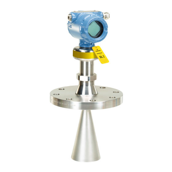
5408 Level Transmitter
™
Non-Contacting Radar with F
Fieldbus Protocol
OUNDATION
Related Manuals for Emerson Rosemount 5408
Summary of Contents for Emerson Rosemount 5408
-
Page 1
Reference Manual 00809-0300-4408, Rev AA June 2019 ™ Rosemount 5408 Level Transmitter ™ Non-Contacting Radar with F Fieldbus Protocol OUNDATION… -
Page 2
Equipment ratings and certifications are no longer valid on any products that have been damaged or modified without the prior written permission of Emerson. Any continued use of product that has been damaged or modified without the written authorization is at the customer’s sole risk and expense. -
Page 3
The products described in this document are NOT designed for nuclear-qualified applications. Using non-nuclear qualified products in applications that require nuclear-qualified hardware or products may cause inaccurate readings. For information on Rosemount nuclear-qualified products, contact your local Emerson Sales Representative. -
Page 5: Table Of Contents
5.5 Change device mode……………………76 5.6 Configure transmitter using Guided Setup………………77 5.7 Verify level……………………….78 5.8 Write protect a transmitter………………….79 Chapter 6 Operation……………………81 6.1 LCD display screen messages………………….81 6.2 Set up the LCD display……………………82 6.3 View measurement data…………………….83 Rosemount 5408 Level Transmitter…
-
Page 6
Contents Reference Manual June 2019 00809-0300-4408 6.4 Device status……………………..85 Chapter 7 Service and troubleshooting………………89 7.1 Safety messages……………………..89 7.2 Diagnostic messages……………………89 ™ 7.3 F Fieldbus error messages…………………96 OUNDATION 7.4 Troubleshooting guides……………………99 7.5 Service and troubleshooting tools………………..105 7.6 Application challenges……………………. -
Page 7
Reference Manual Contents 00809-0300-4408 June 2019 D.2 Analog Input block……………………239 D.3 Measurement Transducer block………………..248 D.4 Register Transducer block………………….252 D.5 Supported units……………………… 254 Rosemount 5408 Level Transmitter… -
Page 8
Contents Reference Manual June 2019 00809-0300-4408 viii Reference Manual… -
Page 9: Chapter 1 Introduction
FOUNDATION Fieldbus Block Information provides information regarding the function blocks. Product recycling/disposal Recycling of equipment and packaging should be taken into consideration and disposed of in accordance with local and national legislation/regulations. Rosemount 5408 Level Transmitter…
-
Page 10
Introduction Reference Manual June 2019 00809-0300-4408 Reference Manual… -
Page 11: Chapter 2 Transmitter Overview
This signal is further processed to obtain fast, reliable, and highly accurate level measurements. See Figure 2-2 for a schematic overview of the signal processing. Figure 2-1: FMCW-method Δf≈d=distance A. Frequency (GHz) B. Time (s) C. Transmitted signal D. Reflected signal Rosemount 5408 Level Transmitter…
-
Page 12: Process Characteristics
Transmitter overview Reference Manual June 2019 00809-0300-4408 Figure 2-2: Flowchart of the Signal Processing A. Microwave module B. A/D converter C. Fast Fourier transform (FFT) D. Peak search E. Peak interpolation F. Echo tracker G. Echo identifier H. Distance filtering I.
-
Page 13
Grain silo — small kernel grains Grain silo — large kernel grains Lime stone silo Possible Cement — raw mill silo Cement — finished product silo Coal bin Saw dust High consistency — pulp stock Alumina Salt Rosemount 5408 Level Transmitter… -
Page 14: Vessel Characteristics
Application examples The Rosemount 5408 is ideal for level measurements over a broad range of liquid and solids applications. The transmitters are virtually unaffected by changing density, temperature, pressure, media dielectric, pH, and viscosity. Non-contacting radar level is ideal for harsh conditions such as corrosive and sticky media, or when internal tank obstructions are a limiting factor.
-
Page 15
00809-0300-4408 June 2019 Blenders and mixers The Rosemount 5408 can help you withstand the rigors of blenders and mixing tanks. Easy to install and commission, it is also unaffected by virtually any fluid property change. Open atmospheric applications The Rosemount 5408 measures reliably in open applications, from short range sumps or ponds to long range dams. -
Page 16: Components Of The Transmitter
Reference Manual June 2019 00809-0300-4408 Bulk solids The Rosemount 5408 is the ideal solution for small to medium sized silos with rapid level changes. The narrow beam avoids internal obstructions while still keeping good level measurement. Components of the transmitter Figure 2-3 shows the different components of the transmitter.
-
Page 17
J. Threaded process connection (NPT or BSPP (G)) K. Air purge ring (option code PC1 for cone antenna) L. Integrated air purge connection M. Parabolic antenna N. Parabolic antenna with swivel mount O. Process seal antenna ® P. Tri-Clamp process connection Rosemount 5408 Level Transmitter… -
Page 18: System Integration
Application), a handheld communicator, the AMS Device Manager, or any other Device Descriptor (DD) or Field Device Integration (FDI) compatible host system. The Rosemount 5408 is compliant with NAMUR NE 107 Field Diagnostics for standardized device diagnostic information. Figure 2-4: System Architecture A.
-
Page 19: Chapter 3 Mechanical Installation
Use the equipment only as specified in this manual. Failure to do so may impair the protection provided by the equipment. • For installations in hazardous locations, the transmitter must be installed according to the Rosemount 5408 and 5408:SIS Product Certifications document and System Control Drawing (D7000002-885).
-
Page 20: Confirm Approval Type
Do not install the transmitter in the center of the tank. • Do not mount close to or above the inlet stream. • Multiple Rosemount 5408 Level Transmitters can be used in the same tank without interfering with each other. Reference Manual…
-
Page 21
Therefore the following minimum clearance, according to Table 3-1, must be maintained. For easy access to the transmitter, mount it with sufficient service space (see Table 3-2). Figure 3-3: Free Space Requirements Rosemount 5408 Level Transmitter… -
Page 22
Mechanical installation Reference Manual June 2019 00809-0300-4408 Table 3-1: Distance to Tank Wall (L) Application Minimum Recommended Liquids 8 in. (200 mm) ½ of tank radius Solids 8 in. (200 mm) ⅔ of tank radius Table 3-2: Free Space Requirements Description Distance Service space width (A) -
Page 23
Beam width and beam angle The transmitter should be mounted with as few internal structures as possible within the signal beam. Refer to Table 3-3 for beam angle and Table 3-4 for beam width at different distances. Rosemount 5408 Level Transmitter… -
Page 24
Mechanical installation Reference Manual June 2019 00809-0300-4408 Figure 3-5: Beam Angle and Beam Width Table 3-3: Beam Angle Antenna size Beam angle (α) 2-in. (DN50) cone/process seal 18° 3-in. (DN80) cone/process seal 14° 4-in. (DN100) cone/process seal 10° 8-in. (DN200) parabolic 4.5°… -
Page 25
Nozzle requirements for process seal antenna The antenna can be used on nozzles up to 4 ft. (1.2 m). Disturbing objects inside the nozzle may impact the measurement, and should therefore be avoided. Rosemount 5408 Level Transmitter… -
Page 26
Mechanical installation Reference Manual June 2019 00809-0300-4408 Figure 3-7: Mounting of the Process Seal Antenna Table 3-6: Nozzle Requirements for Process Seal Antenna Antenna size Minimum nozzle diameter (D) Recommended maximum nozzle height 2-in. (DN50) 1.77 in. (45 mm) 4 ft. (1.2 m) 3-in. -
Page 27
Minimum distance between holes is 6 in. (150 mm). • Holes should be drilled on one side only and deburred. • Drill one hole above maximum product surface. Antenna • All cone/process seal antenna sizes can be used for still pipe/chamber installations. Rosemount 5408 Level Transmitter… -
Page 28
Mechanical installation Reference Manual June 2019 00809-0300-4408 • The gap between the cone antenna and the still pipe should be maximum 0.2 in. (5 mm). If required, order a larger antenna and cut on location. See Table A-15 for antenna dimensions. Figure 3-9: Still Pipe Requirements A. -
Page 29
Ensure there is no edge between the ball valve and the nozzle or still pipe, the inside should be smooth. • Valves can be combined with still pipes. • The ball valve should have the same inner diameter as the still pipe. Rosemount 5408 Level Transmitter… -
Page 30: Mounting Preparations
Mechanical installation Reference Manual June 2019 00809-0300-4408 Mounting preparations 3.4.1 Assemble the segmented cone antenna This section applies to the segmented cone antenna (option code S2). Use only one segment; the total antenna length should not exceed 47.2 in. (1200 mm). To determine the antenna length, follow the guidelines in section Nozzle requirements.
-
Page 31
8. Update the transmitter configuration to the new Antenna Extension Length (L). • Rosemount Radar Master Plus: — Under Configure, select Level Setup → Antenna. • AMS Device Manager and handheld communicator: — Select Configure → Manual Setup → Level Setup → Antenna. Rosemount 5408 Level Transmitter… -
Page 32
Mechanical installation Reference Manual June 2019 00809-0300-4408 3.4.2 Shorten the extended cone antenna This section only applies to the extended cone antenna (option code S1). To determine the antenna length, follow the guidelines in section Nozzle requirements. Procedure 1. Mark where to cut the antenna. 2. -
Page 33
1. Remove the stop ring using a flat head screwdriver. Wear gloves to increase grip when using the tool! 2. Replace the transmitter head nut. 3. Mount the stop ring. Use the new stop ring supplied with the kit. Rosemount 5408 Level Transmitter… -
Page 34: Mount The Cone Antenna
Mechanical installation Reference Manual June 2019 00809-0300-4408 Postrequisites Ensure to set the Antenna Type to Legacy (Rosemount 5402), and then set the User Defined Antenna Options parameters. Related information User defined antenna options Mount the cone antenna 3.5.1 Overview Figure 3-11: Overview A.
-
Page 35
Assemble the segmented cone antenna). Procedure 1. Place a suitable gasket on the tank flange. 2. Lower transmitter with antenna and flange into the nozzle. 3. Tighten bolts and nuts with sufficient torque for the flange and gasket choice. Rosemount 5408 Level Transmitter… -
Page 36
Mechanical installation Reference Manual June 2019 00809-0300-4408 Postrequisites Align the transmitter head (see Align transmitter head). 3.5.4 Flanged version with air purge ring (option code PC1) Prerequisites If applicable, assemble the segmented cone antenna (see Assemble the segmented cone antenna). Procedure 1. -
Page 37
5. Tighten bolts and nuts with sufficient torque for the flange and gasket choice. A. 1.0 in. (25.5 mm) 6. Connect the air purging system. Use thread sealant or suitable gasket according to your site procedures. A. G⅜-in. B. 0.4 in. (10 mm) Rosemount 5408 Level Transmitter… -
Page 38
Mechanical installation Reference Manual June 2019 00809-0300-4408 Table 3-8: Incoming Air Supply Specification Maximum pressure Recommended pressure 190 psi (13 bar) 100 to 115 psi (7 to 8 bar) Postrequisites Align the transmitter head (see Align transmitter head). 3.5.5 Threaded version, antenna diameter smaller than thread diameter Threaded tank connection Prerequisites… -
Page 39
3. Tighten the bolts and nuts with sufficient torque for the flange and gasket choice. 4. Apply anti-seize paste or PTFE tape on threads according to your site procedures. Gasket may be used as a sealant for adapters with 1½- or 2-in. BSPP (G) threads. Rosemount 5408 Level Transmitter… -
Page 40
Mechanical installation Reference Manual June 2019 00809-0300-4408 5. Lower transmitter with antenna into the nozzle. A. Gasket (for 1½-in. and 2-in. BSPP (G) threads only) Postrequisites Align the transmitter head (see Align transmitter head). 3.5.6 Threaded version, antenna diameter larger than thread diameter Prerequisites If applicable, assemble the segmented cone antenna (see… -
Page 41
Gasket may be used as a sealant for adapters with 1½- or 2-in. BSPP (G) threads. 3. Mount the adapter on the customer supplied flange. A. Gasket (for 1½-in. and 2-in. BSPP (G) threads only) 4. Mount the antenna. Note Visually inspect the microwave launcher for damage and dirt. Rosemount 5408 Level Transmitter… -
Page 42
Mechanical installation Reference Manual June 2019 00809-0300-4408 Torque 5 in-lb (0.5 N-m) H2 mm Torque 250 in-lb (28 N-m) 38 mm 5. Place a suitable gasket on the tank flange. 6. Lower transmitter with antenna and flange into the nozzle. 7. -
Page 43: Bracket Mounting
B. Vertical pipe On wall: 2. Mount the holder to the bracket. 3. Unscrew and remove the antenna. H2 mm Note Be careful not to scratch the microwave launcher. The microwave launcher is sensitive to mechanical impacts. Rosemount 5408 Level Transmitter…
-
Page 44
Mechanical installation Reference Manual June 2019 00809-0300-4408 4. Screw the transmitter into the holder. 5. Mount the antenna. Torque 5 in-lb (0.5 N-m) H2 mm 38 mm Postrequisites Align the transmitter head (see Align transmitter head). 3.5.8 Align transmitter head Procedure 1. -
Page 45
Align the external ground screw toward the holes of the still pipe (see Figure 3-14). Chamber Align the external ground screw toward the process connections (see Figure 3-15). 3. Tighten the nut. Torque 355 in-lb (40 N-m) 60 mm Figure 3-13: Open Tank Figure 3-14: Still pipe Rosemount 5408 Level Transmitter… -
Page 46: Mount The Process Seal Antenna
Mechanical installation Reference Manual June 2019 00809-0300-4408 Figure 3-15: Chamber Mount the process seal antenna 3.6.1 Overview Figure 3-16: Overview A. Flanged version (see page ® B. Tri-Clamp version (see page 3.6.2 Mount the flanged version Procedure 1. Lower the transmitter into the nozzle. Reference Manual…
-
Page 47
The conditions used for the calculation are: Standard mating metal flange, A193 B8M Cl.2 / A4-70 bolt material, and a friction coefficient of μ=0.16. Low strength bolt and non-metallic mating flange may require lower tightening torque. Postrequisites Align the transmitter head (see Align transmitter head). Rosemount 5408 Level Transmitter… -
Page 48
Mechanical installation Reference Manual June 2019 00809-0300-4408 ® 3.6.3 Mount the Tri-Clamp version Procedure 1. Lower the transmitter into the nozzle. Note Be careful not to scratch or otherwise damage the PTFE sealing. 2. Tighten the clamp to the recommended torque (see the manufacturer’s instruction manual). -
Page 49: Mount The Parabolic Antenna
Reference Manual Mechanical installation 00809-0300-4408 June 2019 Mount the parabolic antenna 3.7.1 Overview Figure 3-17: Overview A. Flanged version (see page B. Threaded version (see page C. Welded version (see page Rosemount 5408 Level Transmitter…
-
Page 50
Mechanical installation Reference Manual June 2019 00809-0300-4408 3.7.2 Components of the parabolic antenna Components of the threaded version Figure 3-18: Components A. Antenna B. Purge plug kit C. Threaded sleeve D. M20 adapter E. Lock nut BSPP (G) 3½-in. F. Antenna adapter with ball joint G. -
Page 51
A. Antenna B. Purge plug kit C. Threaded sleeve D. M20 adapter E. Weld protection plate F. Flange ball G. O-ring H. Clamp flange I. Washer J. M8 screw K. Weld protection bar L. Ball joint Rosemount 5408 Level Transmitter… -
Page 52
Mechanical installation Reference Manual June 2019 00809-0300-4408 3.7.3 Mount the flanged version Procedure 1. Place a suitable gasket on the tank flange. 2. Lower the flange and antenna assembly into the nozzle. 3. Tighten the bolts and nuts with sufficient torque for the flange and gasket choice. Postrequisites 1. -
Page 53
A. Ø 3.98 ± 0.02 in. (Ø 101 ± 0.6 mm) or G 3½-in. B. Max. 0.59 in. (15 mm) 4. Remove the M20 adapter and visually inspect the O-rings for damage and dirt. Rosemount 5408 Level Transmitter… -
Page 54
Mechanical installation Reference Manual June 2019 00809-0300-4408 5. Carefully insert the antenna. 6. Secure the antenna. Torque 180 in-lb (20 N-m) 27 mm 7. Tighten the set screw. Torque 5 in-lb (0.5 N-m) H2 mm 8. Place a suitable gasket on the tank flange. Reference Manual… -
Page 55
10. Tighten the bolts and nuts with sufficient torque for the flange and gasket choice. Postrequisites 1. Adjust the inclination of the antenna (see Adjust the inclination of the antenna). 2. Connect the air purging system (see Connect the air purging). Rosemount 5408 Level Transmitter… -
Page 56
Mechanical installation Reference Manual June 2019 00809-0300-4408 3.7.5 Mount the welded version Procedure 1. Mount the protection plates to flange/manhole cover. These plates protect the internal surfaces of the flange ball from dust and sparks during welding. A. Ø 3.94 ± 0.02 in. (Ø 100 ± 0.5 mm) B. -
Page 57
Insert the ball joint and place the clamp flange with the “7 Nm” marking side b) Gradually tighten the M8 screws. Torque 65 in-lb (7 N-m) H6 mm 6. Remove the M20 adapter and visually inspect the O-rings for damage and dirt. Rosemount 5408 Level Transmitter… -
Page 58
Mechanical installation Reference Manual June 2019 00809-0300-4408 7. Carefully insert the antenna. 8. Secure the antenna. Torque 180 in-lb (20 N-m) 27 mm 9. Tighten the set screw. Reference Manual… -
Page 59
12. Tighten the bolts and nuts with sufficient torque for the flange and gasket choice. Postrequisites 1. Adjust the inclination of the antenna (see Adjust the inclination of the antenna). 2. Connect the air purging system (see Connect the air purging). Rosemount 5408 Level Transmitter… -
Page 60
Mechanical installation Reference Manual June 2019 00809-0300-4408 3.7.6 Adjust the inclination of the antenna Prerequisites WARNING Contents may be under pressure. • Do not loosen the M8 screws while in operation. Attempting to do so may release pressurized gases, resulting in serious injury or death. Procedure 1. -
Page 61
Reference Manual Mechanical installation 00809-0300-4408 June 2019 4. Adjust the inclination of the antenna. 5. Gradually tighten the M8 screws. Torque 65 in-lb (7 N-m) H6 mm 6. Remove the circular level. Rosemount 5408 Level Transmitter… -
Page 62
Mechanical installation Reference Manual June 2019 00809-0300-4408 7. Mount the transmitter head. Align the marking on the sensor module with the air purge connection. Torque 355 in-lb (40 N-m) 60 mm 36 mm Reference Manual… -
Page 63
D. Use thread sealant or gasket according to your site procedures. E. G⅜-in. F. 0.3-0.4 in. (8-10 mm) (gasket excluded) Table 3-10: Incoming Air Supply Specification Maximum pressure Recommended pressure 190 psi (13 bar) 100 to 115 psi (7 to 8 bar) Rosemount 5408 Level Transmitter… -
Page 64: Adjust Display Orientation (Optional)
Mechanical installation Reference Manual June 2019 00809-0300-4408 Adjust display orientation (optional) To improve field access to wiring or to better view the optional LCD display: Prerequisites Note In high vibration applications, the transmitter housing must be fully engaged into the sensor module to meet the vibration test specifications.
-
Page 65: Chapter 4 Electrical Installation
Use the equipment only as specified in this manual. Failure to do so may impair the protection provided by the equipment. • For installations in hazardous locations, the transmitter must be installed according to the Rosemount 5408 and 5408:SIS Product Certifications document and System Control Drawing (D7000002-885).
-
Page 66: Hazardous Areas
Electrical installation Reference Manual June 2019 00809-0300-4408 Hazardous areas When the transmitter is installed in hazardous areas, local regulations, and specifications in applicable certificates must be observed. Related information Product Certifications Prepare the electrical connections 4.3.1 Cable selection Recommended wiring is 18 AWG twisted shielded pair, referred to as Fieldbus type A cable.
-
Page 67
4.3.5 Power supply The transmitter operates on 9-32 Vdc (9-30 Vdc in Intrinsically Safe installations and 9-17.5 Vdc for FISCO) at the transmitter terminals. Rosemount 5408 Level Transmitter… -
Page 68: Wiring Diagram
Electrical installation Reference Manual June 2019 00809-0300-4408 4.3.6 Signal termination A terminator should be installed at the beginning and end of every Fieldbus segment. For transmitter with built-in terminator, connect a jumper wire between the «TERMINATE ON» terminals to activate the terminator. Refer to Cable selection for recommended wire size.
-
Page 69: Connect Wiring And Power Up
D. Daisy-chain connection to other devices E. Handheld communicator F. Fieldbus modem G. Power supply ™ H. Rosemount 2410 Tank Hub Connect wiring and power up Procedure Verify the power supply is disconnected. 2. Remove the cover. Rosemount 5408 Level Transmitter…
-
Page 70
Electrical installation Reference Manual June 2019 00809-0300-4408 3. Remove the plastic plugs. 4. Pull the cable through the cable gland/conduit. Identification of thread size and type: 5. Connect the cable wires (see Wiring diagram). Torque 7 in-lb (0.8 N-m) 6. Ensure proper grounding (see Grounding). 7. -
Page 71
Verify the cover jam screw is completely threaded into the housing. H2.5 mm b) Attach and tighten the cover. Make sure the cover is fully engaged. There should be no gap between the cover and the housing. Rosemount 5408 Level Transmitter… -
Page 72
Electrical installation Reference Manual June 2019 00809-0300-4408 c) Turn the jam screw counterclockwise until it contacts the cover. Required for explosion-proof/flameproof installations only. d) Turn the jam screw an additional ½ turn counterclockwise to secure the cover. 10. Connect the power supply. Note It may take up to 15 seconds before the LCD display lights up. -
Page 73: Chapter 5 Configuration
High voltage that may be present on leads can cause electrical shock. Overview This chapter provides information about configuration and configuration tools. Appendix Configuration parameters provides extended information about the configuration parameters. The menu trees can be found in Menu tree. Rosemount 5408 Level Transmitter…
-
Page 74: System Readiness
5-1, use the Device Revision number to find the correct DD or FDI Package. 2. Download the latest DD at Emerson.com/DeviceInstallKits. 3. Download the latest FDI Package at Emerson.com/RosemountRadarMasterPlus. Table 5-1: Identification and Compatibility According to NAMUR NE 53 Release…
-
Page 75
The Device Descriptor (DD) is a configuration tool that is developed to assist the user through the configuration. Prerequisites The Rosemount 5408 DD is typically installed together with AMS Device Manager. To download the latest DD, visit the Emerson Device Install Kit site at: Emerson.com/DeviceInstallKits… -
Page 76: Change Device Mode
Get the latest Device Descriptor (DD) If the DD is not installed in your handheld communicator, see the appropriate handheld communicator User’s Manual available at Emerson.com/FieldCommunicator instructions on how to update the handheld communicator with the latest DD. Change device mode 5.5.1…
-
Page 77: Configure Transmitter Using Guided Setup
The options available in the Guided Setup wizard include all items required for basic operation. Procedure 1. Turn on the handheld communicator and connect to the device. 2. Select Configure → Guided Setup. 3. Select Basic Setup and follow the on-screen instructions. Rosemount 5408 Level Transmitter…
-
Page 78: Verify Level
Configuration Reference Manual June 2019 00809-0300-4408 Verify level The Verify Level tool matches the product level reported by the device to a reference measurement (measured by using for example handgauging). If any difference, the Calibration Offset parameter will be adjusted. A minor adjustment using Calibration Offset is normal.
-
Page 79: Write Protect A Transmitter
Write protect a transmitter using AMS Device Manager and handheld communicator The transmitter can be write protected to prevent unauthorized changes. Procedure 1. Select Configure → Manual Setup → Device Setup → Security. 2. Select Change Write Protection and follow the on-screen instructions. Rosemount 5408 Level Transmitter…
-
Page 80
Configuration Reference Manual June 2019 00809-0300-4408 Reference Manual… -
Page 81: Chapter 6 Operation
The following screens are shown on the LCD display when the transmitter is switched on: Figure 6-2: Startup Screen Sequence 1. All segments on 2. Device type and 3. Software revision 4. Serial number communication protocol Variable screens The transmitter can display the following variables: Rosemount 5408 Level Transmitter…
-
Page 82: Set Up The Lcd Display
Operation Reference Manual June 2019 00809-0300-4408 Table 6-1: LCD Display Variables Parameter Presentation on display Description Level LEVEL The current level measurement value. Distance DIST Distance from the upper reference point to the product surface. Level Rate The current velocity at which the level is moving.
-
Page 83: View Measurement Data
Current measurement data of the primary variables are presented on the Overview screen together with a graphical representation of the tank. Procedure Select All Variables to view a complete list of all variables within the transmitter. Rosemount 5408 Level Transmitter…
-
Page 84
Operation Reference Manual June 2019 00809-0300-4408 Figure 6-3: Rosemount Radar Master Plus — Overview Screen 6.3.2 View measurement data in AMS Device Manager and handheld communicator Current measurement data of the primary variables are presented on the Overview screen. To view all current measurement values, do the following: Procedure 1. -
Page 85: Device Status
High/low user defined alert 6.4.1 Check device status Follow this procedure to check device status and see whether there are any active alerts reported. Procedure 1. Go to the Overview screen to view the overall device status. Rosemount 5408 Level Transmitter…
-
Page 86
Operation Reference Manual June 2019 00809-0300-4408 2. If status is anything than Good, click the button in the device status image to open a window with active alerts. The different device status images are shown in Table 6-2 Table 6-3. Active Alerts can also be obtained via Service Tools →… -
Page 87
At least one Out of Specification Specification alert is active (and no Failure or Function Check alerts). Maintenance At least one Maintenance Required Required alert is active (and no Failure, Function Check, or Out of Specification alerts). Rosemount 5408 Level Transmitter… -
Page 88
Operation Reference Manual June 2019 00809-0300-4408 Reference Manual… -
Page 89: Service And Troubleshooting
Make sure the mains power to the transmitter is off and the lines to any other external power source are disconnected or not powered while wiring the transmitter. Diagnostic messages Diagnostic messages per NAMUR NE 107 are listed in Table 7-1 Table 7-5. Rosemount 5408 Level Transmitter…
-
Page 90
Service and troubleshooting Reference Manual June 2019 00809-0300-4408 Table 7-1: Status — Failed LCD display Host diagnostic Description Recommended actions message message ELEC Electronics Failure, An electronics error has occurred. 1. Restart the device. Transmitter FAILUR The device measurement reading is 2. -
Page 91
ERROR multiple (see Table 7-2 for details). 2. Correct the parameter causing the error. DD4: 1. Check ALERT_CONFIG_DETAILS parameter for details. 2. Correct the issue causing configuration error. 3. Restore default settings and reconfigure device. Rosemount 5408 Level Transmitter… -
Page 92
Service and troubleshooting Reference Manual June 2019 00809-0300-4408 Table 7-2: Configuration Error Details Host diagnostic message Description Recommended actions Volume Configuration Error The volume cannot be calculated correctly 1. If strapping table is used, check that with the current configuration. level-volume values are entered in increasing order. -
Page 93
Upgrade function. Note 2. If condition persists, contact your Start codes are unique for individual local Emerson representative to get a devices and cannot be copied from one valid start code. device to another. Table 7-3: Status — Function Check… -
Page 94
Service and troubleshooting Reference Manual June 2019 00809-0300-4408 Table 7-3: Status — Function Check (continued) LCD display Host diagnostic Description Recommended actions message message OUTOF Device Not in Service One or more blocks in the device • Change block mode to Auto to are not in service. -
Page 95
1. Check configuration of Bottom Estimation Degraded degraded. Product Dielectric Constant. DEGRAD 2. Check configuration of Accuracy of level measurement may Reference Height and Bottom be degraded. Offset. 3. If not needed, disable Tank Bottom Projection. Rosemount 5408 Level Transmitter… -
Page 96: Foundation ™ Fieldbus Error Messages
Service and troubleshooting Reference Manual June 2019 00809-0300-4408 ™ Fieldbus error messages OUNDATION 7.3.1 Resource block errors Table 7-6 lists conditions reported in the BLOCK_ERR parameter. Table 7-6: Resource Block BLOCK_ERR Conditions Condition Condition name Description number Other A device specific error has occurred. Block Configuration Error There is a configuration error in resource block such as wrong…
-
Page 97
Check XD_SCALE parameter. correct. If using Indirect mode, scaling • Check OUT_SCALE parameter. (see could be wrong XD_SCALE and OUT_SCALE). OUT parameter status reads Out_ScaleEU_0 and EU_100 settings are XD_SCALE and OUT_SCALE. UNCERTAIN and substatus incorrect. reads EngUnitRangViolation Rosemount 5408 Level Transmitter… -
Page 98
Service and troubleshooting Reference Manual June 2019 00809-0300-4408 Table 7-8: Troubleshooting the AI Block (continued) Symptom Possible causes Recommended actions Mode will not leave OOS Target mode not set Set target mode to something other than OOS. Configuration error BLOCK_ERR will show the configuration error bit set. -
Page 99: Troubleshooting Guides
(especially the Reference Height). • Run Verify Level to adjust level measurement, see Verify level. • Analyze the echo curve and check amplitude thresholds, see Amplitude thresholds. • Restore default settings and Time reconfigure the device. Rosemount 5408 Level Transmitter…
-
Page 100
Service and troubleshooting Reference Manual June 2019 00809-0300-4408 Table 7-11: Incorrect Level Readings (continued) Symptom Possible causes Recommended actions Level is stuck in measuring range. Incorrect alignment of the • Verify the transmitter head is correctly transmitter. aligned, see Align transmitter head. -
Page 101
Analyze the echo curve and check tank with the amplitude amplitude thresholds, see Amplitude threshold set too low. thresholds. The product surface is close If possible, remove the disturbing object. to a suppressed false echo. Time Rosemount 5408 Level Transmitter… -
Page 102
Service and troubleshooting Reference Manual June 2019 00809-0300-4408 Table 7-11: Incorrect Level Readings (continued) Symptom Possible causes Recommended actions Measured level lags during rapid level Damping value too high. If there is a problem with lag during rapid changes. level changes, consider decreasing the Damping value, see Damping value. -
Page 103
Empty Tank Detection Area, see Empty tank handling. • Verify the Bottom echo visible when tank is empty parameter is disabled, Enable bottom echo visible when tank is empty. Time = actual level = reported level Rosemount 5408 Level Transmitter… -
Page 104
Service and troubleshooting Reference Manual June 2019 00809-0300-4408 ™ 7.4.2 Troubleshooting the F Fieldbus output OUNDATION Table 7-12: Troubleshooting the F Fieldbus Output OUNDATION Symptom Possible causes Recommended actions Transmitter does not show up on No power to transmitter • Ensure the transmitter is segment connected to the segment. -
Page 105: Service And Troubleshooting Tools
Service and troubleshooting tools This section briefly describes tools and functions in the Rosemount Radar Master Plus, AMS Device Manager, and handheld communicator, which may be useful for service and troubleshooting of the Rosemount 5408 Level Transmitter. 7.5.1 Using the echo curve The Rosemount Radar Master Plus software includes functions for viewing and recording single instances or movies of the echo curve.
-
Page 106
Service and troubleshooting Reference Manual June 2019 00809-0300-4408 Figure 7-1: Echo Curve Measurement problems can be understood by studying the position and amplitude of the different peaks. Additionally, the recorded echo curves give insight into unexpected and intermittent measurement behaviors, for instance, at the time of the triggered alert. Read the echo curve To read the echo curve in Rosemount Radar Master Plus: Procedure… -
Page 107
You can zoom in to a specific area of the echo curve. Procedure • To zoom in, drag a rectangle around the area you want to magnify. • To zoom out, in the upper right corner of the echo curve, select Reset Zoom. Rosemount 5408 Level Transmitter… -
Page 108
Service and troubleshooting Reference Manual June 2019 00809-0300-4408 View level trends and historical echo curves Procedure • To go to a desired point in the displayed part of the timeline, drag the slider, or click anywhere in the timeline. • To move the timeline forward or backward, click the left or right arrow, or drag anywhere in the timeline. -
Page 109
To set the resolution of the level trend timeline: Procedure 1. Under Service Tools, select Echo Curve. 2. Select Options. 3. In the Timeline Resolution list, select the desired length (in hours) of the timeline. 4. Select Save. 5. Select Back. Rosemount 5408 Level Transmitter… -
Page 110
Service and troubleshooting Reference Manual June 2019 00809-0300-4408 7.5.2 Managing disturbance echoes There are two general methods for managing disturbance echoes: • Set amplitude thresholds to filter out weak disturbance echoes and noise. • Use the suppress false echoes function to manage strong disturbance echoes. Amplitude thresholds The amplitude thresholds are used to filter out noise and disturbing echoes from the product surface echo. -
Page 111
A. Amplitude threshold point Set the endpoint of a threshold segment Procedure 1. In the echo curve, drag the endpoint up or down, or type the desired value (Figure 7-5). 2. Select Save. Figure 7-5: Endpoint A. Endpoint Rosemount 5408 Level Transmitter… -
Page 112
Service and troubleshooting Reference Manual June 2019 00809-0300-4408 Add or delete an amplitude threshold point Procedure 1. In the echo curve, select the desired amplitude threshold point, and select Split threshold or Merge with threshold below. 2. Click again on one of the amplitude threshold points and select Save. Suppressing false echoes Stationary objects with horizontal surfaces may generate strong false echoes. -
Page 113
2. In the echo curve, click at the unknown echo peak, and then select Suppress. Figure 7-7: Add False Echo Suppression Delete a false echo suppression Procedure 1. In Rosemount Radar Master Plus, under Service Tools, select Echo Curve. Rosemount 5408 Level Transmitter… -
Page 114
Service and troubleshooting Reference Manual June 2019 00809-0300-4408 2. In the echo curve, click at the left end of the false echo suppression, and then select Delete. Figure 7-8: Delete False Echo Suppression Suppress a false echo manually The false echo may also be suppressed manually if the position of the false echo is known. Procedure 1. -
Page 115
5. Optional: Select the Create and save report (.pdf) check box. 6. Select Save. 7.5.4 Download configuration from file to device Procedure 1. In Rosemount Radar Master Plus, under Service Tools, select Maintenance → Backup . Rosemount 5408 Level Transmitter… -
Page 116
Service and troubleshooting Reference Manual June 2019 00809-0300-4408 2. Select Restore Configuration. 3. Browse to the backup file and select Open. 7.5.5 Restore to default settings Restore to default settings using Rosemount Radar Master Plus This function restores the transmitter to default settings (user configuration is overwritten). -
Page 117
Procedure 1. Under Configure, select Level Setup → Advanced. 2. Under More Advanced Options, select Expert Options. 3. Select the Input Registers tab. 4. Under Show registers by, do one of the following: Rosemount 5408 Level Transmitter… -
Page 118
Service and troubleshooting Reference Manual June 2019 00809-0300-4408 • Select Block, and then in the list, select the desired register group. • Select Number, and then type the desired register number and the number of registers. 5. Select Refresh. View input registers using AMS Device Manager and handheld communicator Measured data is continuously stored in the input registers. -
Page 119: Application Challenges
Select Write Holding Register and follow the on-screen instructions. Application challenges 7.6.1 Handling disturbances at top of tank There are two general methods for managing disturbance echoes at the top of the tank: • Set amplitude threshold section • Extend the Upper Null Zone Rosemount 5408 Level Transmitter…
-
Page 120
Service and troubleshooting Reference Manual June 2019 00809-0300-4408 Set amplitude threshold section If necessary, a customized amplitude threshold section can be used to block out disturbing echoes (e.g. from the tank nozzle or bypass well inlet). Refer to Amplitude thresholds for general guidelines. -
Page 121
Under Configure, select Level Setup → Antenna. b) Under Advanced, type desired Upper Null Zone, and then select Save. Figure 7-10: Upper Null Zone A. Upper Null Zone B. Disturbance echo C. Amplitude threshold D. Product surface echo Rosemount 5408 Level Transmitter… -
Page 122
Service and troubleshooting Reference Manual June 2019 00809-0300-4408 7.6.2 Tracking of weak surface echoes close to tank bottom Use tank bottom projection The Tank Bottom Projection function can be used to enhance measurement performance in the tank bottom region. If the product surface echo is weak in the tank bottom region and the bottom echo is strong (typical for flat tank bottoms), the transmitter may lock on the bottom echo and report a false level measurement (empty tank). -
Page 123
F. Echo peak from tank bottom (at the electrical distance when product in the tank) Prerequisites Note Only enable this parameter if a bottom echo is visible when tank is empty. To verify this, use the echo curve function. Rosemount 5408 Level Transmitter… -
Page 124
Service and troubleshooting Reference Manual June 2019 00809-0300-4408 Procedure 1. In Rosemount Radar Master Plus, under Configure, select Level Setup → Advanced. 2. Under More Advanced Options, select Empty Tank Handling. 3. In the Empty Tank Handling list, select User Defined. 4. -
Page 125
A double bounce echo occurs when a radar signal bounces back and forth between the product surface and tank roof (or other object within the tank) before it is detected by the transmitter. Normally, these signals have a low amplitude and are ignored by the transmitter. Rosemount 5408 Level Transmitter… -
Page 126
Service and troubleshooting Reference Manual June 2019 00809-0300-4408 Figure 7-14: Double Bounce Echoes A. Distance to surface B. Distance to first double bounce C. Actual level D. Virtual level (first double bounce) E. Signal amplitude F. Distance Prerequisites Note The Double Bounce Handling function should only be used if the problem of double bounces cannot be solved by changing the mounting position. -
Page 127: Replace The Transmitter Head
1. Disconnect the power supply. 2. If applicable, remove the external ground cable from the transmitter head. 3. Turn the jam screw clockwise until it is completely threaded into the housing. H2.5 mm 4. Remove the cover. Rosemount 5408 Level Transmitter…
-
Page 128
Service and troubleshooting Reference Manual June 2019 00809-0300-4408 5. Remove all electrical leads and disconnect conduit. 6. Loosen the nut that connects the transmitter head to the process seal. 60 mm 7. Carefully lift the transmitter head. Do not attempt to loosen it by rotating the transmitter head. If it is stuck, then it may need to be replaced with a new process connection and transmitter head, by following all plant safety rules and procedures. -
Page 129: Cleaning Or Replacing The Ptfe Sealing
Remove from service Be aware of the following: • Follow all plant safety rules and procedures. • In Explosion Proof/Flameproof and Non-Incendive/Type n installations, do not remove the transmitter covers when power is applied to the unit. Rosemount 5408 Level Transmitter…
-
Page 130
Service and troubleshooting Reference Manual June 2019 00809-0300-4408 • Do not remove the process connection while in operation. Removing while in operation may cause process gas leaks. Cleaning To avoid electrostatic charges, use only a damp cloth to clean the PTFE surfaces. Clean the PTFE sealing with care. -
Page 131
3. Gently insert the PTFE sealing until it stops, and then firmly push it all the way in. ® 7.8.2 Tri-Clamp version Disassembly procedures Procedure 1. Insert a wide flathead screwdriver into the groove at the base of the PTFE sealing. Rosemount 5408 Level Transmitter… -
Page 132
Service and troubleshooting Reference Manual June 2019 00809-0300-4408 2. Gently wiggle the screwdriver back and forth. Note Be careful not to scratch or depress the PTFE surfaces (facing the process). 3. Repeat Step 1-Step 2 at different positions until the PTFE sealing is loose. 4. -
Page 133: Service Support
2. Verify the O-ring on the PTFE sealing is in place. 3. Gently insert the PTFE sealing until it stops, and then firmly push it all the way in. Service support To expedite the return process outside of the United States, contact the nearest Emerson representative. Rosemount 5408 Level Transmitter…
-
Page 134
Reference Manual June 2019 00809-0300-4408 Within the United States, call the Emerson Instrument and Valve Response Center using the 1-800-654-RSMT (7768) toll-free number. This center, available 24 hours a day, will assist you with any needed information or materials. The center will ask for product model and serial numbers, and will provide a Return Material Authorization (RMA) number. -
Page 135: Appendix A Specifications And Reference Data
Refers to inaccuracy according to IEC 60770-1 when excluding installation dependent offset. See the IEC 60770-1 standard for a definition of radar specific performance parameters and if applicable corresponding test procedures. Ambient temperature effect specification valid over temperature range -40 °F to 176 °F (-40 °C to 80 °C). Rosemount 5408 Level Transmitter…
-
Page 136
June 2019 00809-0300-4408 A.1.2 Measuring range Maximum measuring range Rosemount 5408: 130 ft. (40 m) Note that a combination of adverse process conditions, such as heavy turbulence, foam, and condensation, together with products with poor reflection may affect the measuring range. -
Page 137
In challenging applications where the dynamic of the transmitter sensitivity is utilized by multiple factors such as small aperture antenna, very low product dielectric constant and/or turbulent surface, the margin for additional influence due to extreme EMC may be limited. Rosemount 5408 Level Transmitter… -
Page 138: Functional Specifications
Specifications and reference data Reference Manual June 2019 00809-0300-4408 Pressure Equipment Directive (PED) Complies with 2014/68/EU article 4.3 Built-in lightning protection EN 61326, IEC 61000-4-5, level 6kV Radio approvals • Radio Equipment Directive (2014/53/EU): ETSI EN 302 372, ETSI EN 302 729 and EN 62479 •…
-
Page 139
Product Data Sheet for more information. Configuration tools • Rosemount Radar Master Plus for Rosemount 5408 Series (accessible through any Field ™ Device Integration (FDI) based tool, e.g Instrument Inspector Application • Device Descriptor (DD) based systems, e.g. AMS Device Manager, 475 Field ™… -
Page 140: Cable Selection
Specifications and reference data Reference Manual June 2019 00809-0300-4408 • Volume: ft , in. , yd , US gal, imperial gal, barrel (bbl), m • Temperature: °F, °C • Signal strength: mV Output variables Table A-2: Output Variables Variable Digital output LCD display ✓…
-
Page 141
Tools and logging in Rosemount Radar Master Plus • Echo curve • Measurement and alert log Rosemount Radar Master Plus, embedded in Instrument Inspector, enables easy and powerful troubleshooting with the echo curve tool as well as the measurement and alert log. Rosemount 5408 Level Transmitter… -
Page 142
Specifications and reference data Reference Manual June 2019 00809-0300-4408 The measurement and alert log holds records of the last seven days of level readings and echo curve profiles, as well as the 50 last alert events. The logs can be transferred from the transmitter’s internal memory to a local computer and be presented in a graphical time line, enabling analysis of historical behaviors. -
Page 143
(-30) (-15) (-1) (-60) (-25) (170) (200) (220) (250) A. Pressure psig (bar) B. Temperature °F (°C) C. Code CBF (FVMQ) ® D. Code CBV (Viton E. Code CBM (FKM) ® F. Code CBK (Kalrez 6375) Rosemount 5408 Level Transmitter… -
Page 144
Specifications and reference data Reference Manual June 2019 00809-0300-4408 Figure A-5: Process Seal Antenna 363 (25) 232 (16) -7 (-0.5) (200) (-60) (-25) A. Pressure psig (bar) B. Temperature °F (°C) C. Tri-Clamp Figure A-6: Parabolic Antenna 43 (3) -7 (-0.5) (200) (-55) A. -
Page 145
1.4404 according to EN 1092-1 material group 13E0 • 316 SST according to JIS B2220 material group No. 2.2 (10) • 316L SST according to JIS B2220 material group No. 2.3 (for protective plate design) (10) Flange rating according to backing flange. Rosemount 5408 Level Transmitter… -
Page 146
Specifications and reference data Reference Manual June 2019 00809-0300-4408 A.2.8 Conditions used for flange strength calculations Table A-4: 316/316L SST (EN 1.4404) Flanges Item ASME EN, JIS ® Bolting material SA193 B8M CL.2, SA193 B7 , or SA320 EN 1515-1/2, ISO 3506 A4-70, or Bumax Gasket Soft (1a) with min. -
Page 147
An air purge connection is also available for cone antennas with flanged connection by selecting option code PC1. This option consists of an antenna with purge holes and a separate air purge ring (see Figure A-9). Rosemount 5408 Level Transmitter… -
Page 148: Physical Specifications
Emerson is not in a position to evaluate or guarantee the compatibility of the process fluid or other process parameters with the product, options, configuration or materials of construction selected.
-
Page 149
All PTFE wetted parts ideal for use in corrosive and hygienic applications (11) Fully functional transmitter with sensor module, housing, terminal block, LCD display, and covers (12) The transmitter meets IP 68 at 9.8 ft. (3 m) for 30 minutes. Rosemount 5408 Level Transmitter… -
Page 150
This declaration is applicable to Tri-Clamp connections. Emerson certifies no process wetted components used in hygienic seal products contain substances of animal origin. Materials used in the production or processing of wetted components for hygienic seals meet the requirements stated in EMA/410/01 Rev. 3 and ISO 22442-1:2015. -
Page 151: Ordering Information
Ordering Information A.4.1 Rosemount 5408 Level Transmitter Table A-8: Rosemount 5408 Level Transmitter Ordering Information The starred offerings (★) represent the most common options and should be selected for best delivery. The non-starred offerings are subject to additional delivery lead time.
-
Page 152
Specifications and reference data Reference Manual June 2019 00809-0300-4408 Table A-8: Rosemount 5408 Level Transmitter Ordering Information (continued) ★ Canadian Intrinsically Safe; Nonincendive ★ Canadian FISCO Intrinsic Safety ★ IECEx Flameproof, Dust Ignition-proof ★ IECEx Intrinsic Safety ★ IECEx Type n ★… -
Page 153
Reference Manual Specifications and reference data 00809-0300-4408 June 2019 Table A-8: Rosemount 5408 Level Transmitter Ordering Information (continued) ASME flanges ★ ASME B16.5 Class 150 ★ ASME B16.5 Class 300 ★ ASME B16.5 Class 600 EN flanges Note ★ EN1092-1 PN6 ★… -
Page 154
Specifications and reference data Reference Manual June 2019 00809-0300-4408 Table A-8: Rosemount 5408 Level Transmitter Ordering Information (continued) (7)(8) Purging connection (see Figure A-9) ★ Purging Connector (Purge Ring) Display ★ LCD Display Diagnostic functionality (see Smart Diagnostics Suite) ★… -
Page 155
Reference Manual Specifications and reference data 00809-0300-4408 June 2019 Table A-8: Rosemount 5408 Level Transmitter Ordering Information (continued) ★ WPQR/WPQ/WPS (10) Dye penetration test certificate ★ Certificate of Liquid Penetrant Inspection Positive material identification certificate ★ Positive Material Identification Certificate of Conformance… -
Page 156: Availability Of Process Connections
Specifications and reference data Reference Manual June 2019 00809-0300-4408 Availability of process connections Table A-9: Cone Antenna — 316/316L SST/EN 1.4404 (Type vs. Size and Rating) Process Process connection rating connection Thread ASME B16.5 flanges EN1092-1 flanges JIS B2220 size flanges Class Class…
-
Page 157: Spare Parts And Accessories
W = Welded connection (process connection type code W) R = Raised Face face (process connection type code R) F = Flat Face face (process connection type code F) Spare parts and accessories Table A-13: Rosemount 5408 Series Spare Parts List — Transmitter Head Model Product Description 5408…
-
Page 158
Specifications and reference data Reference Manual June 2019 00809-0300-4408 Table A-13: Rosemount 5408 Series Spare Parts List — Transmitter Head (continued) Performance class Standard Signal output ™ Fieldbus OUNDATION Housing material Aluminum Stainless Steel (SST) Conduit/cable threads ½-14 NPT M20 x 1.5 G½… -
Page 159
Reference Manual Specifications and reference data 00809-0300-4408 June 2019 Table A-13: Rosemount 5408 Series Spare Parts List — Transmitter Head (continued) Process connection rating None (Spare Transmitter Head) Antenna type None (Spare Transmitter Head) Antenna size None (Spare Transmitter Head) -
Page 160
Rosemount 5408 is backward compatible with the full range of Rosemount 5402 antennas manufactured after September 2013, when ordered with the appropriate adapter (option code A1). The Rosemount 5408 transmitter head can also be ordered with a Rosemount 5402 antenna, or pre-configured to an existing Rosemount 5402 antenna. -
Page 161
Reference Manual Specifications and reference data 00809-0300-4408 June 2019 Table A-14: Rosemount 5408 Series Spare Parts List — Antenna (continued) Ring Type Joint (RTJ) Flange Process connection size (see Table A-9, Table A-10, Table A-11, and Table A-12) Available antenna types 1½-in. -
Page 162
Specifications and reference data Reference Manual June 2019 00809-0300-4408 Table A-14: Rosemount 5408 Series Spare Parts List — Antenna (continued) Cone Antenna (PEEK seal, FKM) -15 to 754 psig (-1 to 52 bar) -13 to 428 °F (-25 to 220 °C) -
Page 163
Reference Manual Specifications and reference data 00809-0300-4408 June 2019 Table A-14: Rosemount 5408 Series Spare Parts List — Antenna (continued) Welder Performance Qualification (WPQ) Welding Procedure Specification (WPS) WPQR/WPQ/WPS Dye penetration test certificate Certificate of Liquid Penetrant Inspection Positive material identification certificate… -
Page 164: Dimensional Drawings
Specifications and reference data Reference Manual June 2019 00809-0300-4408 Dimensional drawings Figure A-10: Cone Antenna with Flanged Process Connection 5.16 (131) 4.21 4.51 (107) (114.5) 4.21 (106.9) 8.27 (210) 10.83 11.02 (275) (280) 0.39 (10) A. See Table A-15 for dimensions. B.
-
Page 165
1.85 in. (47 mm) 5.39 in. (137 mm) 3-in. (DN80) 6.02 in. (153 mm) 2.64 in. (67 mm) 6.77 in. (172 mm) 4-in. (DN100) 6.93 in. (176 mm) 3.62 in. (92 mm) 7.80 in. (198 mm) Rosemount 5408 Level Transmitter… -
Page 166
Specifications and reference data Reference Manual June 2019 00809-0300-4408 Figure A-12: Extended Cone Antenna 23.6 (600) 47.2 (1200) A. Option code S1 B. Option code S2 Dimensions are in inches (millimeters). Reference Manual… -
Page 167
B. ½-14 NPT, M20 x 1.5, or G½; optional adapters: eurofast and minifast C. s60 D. 3-, 4-in. process seal style ® E. 2-in. Tri-Clamp F. 3-in. Tri-Clamp G. 4-in. Tri-Clamp Dimensions are in inches (millimeters). Rosemount 5408 Level Transmitter… -
Page 168
Specifications and reference data Reference Manual June 2019 00809-0300-4408 Figure A-14: Parabolic Antenna 5.16 (131) 4.21 4.51 (107) (114.5) 4.21 (106.9) 8.27 (210) 11.34 (288) 2.46 (62.4) 7.40 (188) 10.35 10.35 (263) (263) 1.14 (29) 1.14 (29) Ø 3.90 (99) 3.43 3.43 (87) (87) -
Page 169
(57) A. Pipe mounting (vertical pipe) B. Pipe diameter, max 2.52 in. (64 mm) C. Pipe mounting (horizontal pipe) D. Wall mounting E. Hole pattern for wall mounting F. NPT 1½-in. Dimensions are in inches (millimeters). Rosemount 5408 Level Transmitter… -
Page 170
Specifications and reference data Reference Manual June 2019 00809-0300-4408 A.7.1 Standard flanges Figure A-16: Cone Antenna Flange Connection A. Forged one-piece B. Welded construction C. Protective plate design D. Weld E. Backing flange F. Protective plate Table A-16: Standard Flanges for Cone Antenna Standard Face type Face surface finish, R… -
Page 171
Table A-18: Standard Flanges for Parabolic Antenna Standard Face type Face surface finish ASME B16.5 Raised face 125-250 µin EN 1092-1 Type A flat face 3.2-12.5 µm JIS B2220 Raised face 3.2-12.5 µm Face gasket surface is serrated per mating standard. Rosemount 5408 Level Transmitter… -
Page 172
Specifications and reference data Reference Manual June 2019 00809-0300-4408 Reference Manual… -
Page 173: Appendix B Product Certifications
5408 and 5408:SIS Product Certifications document. The most recent revision of the EU Declaration of Conformity can be found at Emerson.com/Rosemount. Ordinary location certification As standard, the transmitter has been examined and tested to determine that the design meets the basic electrical, mechanical, and fire protection requirements by a nationally recognized test laboratory (NRTL) as accredited by the Federal Occupational Safety and Health Administration (OSHA).
-
Page 174
Product Certifications Reference Manual June 2019 00809-0300-4408 and used in accordance with the instructions, may cause harmful interference to radio communications. However, there is no guarantee that interference will not occur in a particular installation. If this equipment does cause harmful interference to radio or television reception, which can be determined by turning the equipment off and on, the user is encouraged to try to correct the interference by one or more of the following measures:… -
Page 175: Radio Equipment Directive (Red) 2014/53/Eu
B.8.1 E5 Explosionproof (XP), Dust-Ignitionproof (DIP) Certificate FM-US FM16US0010X Standards FM Class 3600 – 2018; FM Class 3615 – 2018; FM Class 3810 – 2005; ANSI/ISA 60079-0 – 2013; ANSI/UL 60079-1 – 2015; ANSI/UL 60079-26 – Rosemount 5408 Level Transmitter…
-
Page 176
Product Certifications Reference Manual June 2019 00809-0300-4408 ® 2017; ANSI/ISA 60079-31 – 2015; ANSI/NEMA 250 – 1991; ANSI/IEC 60529 – 2014, ANSI/ISA 12.27.01:2011 Markings XP CL I, DIV 1, GRPS A, B, C, D T6…T2 DIP CLII/III, DIV 1, GRPS E, F, G; T6…T3 CL I Zone 0/1 AEx db IIC T6…T2 Ga/Gb Zone 21 AEx tb IIIC T85 °C…T250 °C Db (14) -
Page 177
I5 Intrinsic Safety (IS), Non-Incendive (NI) Certificate FM-US FM16US0010X Standards FM Class 3600 – 2018; FM Class 3610 – 2018; FM Class 3611 – 2018; FM Class 3810 – 2005; ANSI/ISA 60079-0 – 2013; ANSI/UL 60079-11 – 2014; Rosemount 5408 Level Transmitter… -
Page 178
Product Certifications Reference Manual June 2019 00809-0300-4408 ® ANSI/UL 60079-26 – 2017; ANSI/NEMA 250 – 1991; ANSI/IEC 60529 – 2014; ANSI/ISA 12.27.01:2011 Markings IS CL I, ll, lll DIV 1, GRPS A-G T4…T2 NI CL I, DIV 2, GRPS A-D T4…T2 S CL Il, lll DIV 2, GRPS E-G T4…T3 CL l Zone 0 AEx ia IIC T4…T2 Ga CL l Zone 0/1 AEx ib IIC T4…T2 Ga/Gb… -
Page 179
250 – 1991; ANSI/IEC 60529 – 2014; ANSI/ISA 12.27.01:2011 Markings IS CL I, ll, lll DIV 1, GRPS A-G T4…T2 NI CL I, DIV 2, GRPS A-D T4…T2 S CL Il, lll DIV 2, GRPS E-G T4…T3 Rosemount 5408 Level Transmitter… -
Page 180
Product Certifications Reference Manual June 2019 00809-0300-4408 CL l Zone 0 AEx ia IIC T4…T2 Ga CL l Zone 0/1 AEx ib IIC T4…T2 Ga/Gb Zone 20 AEx ia IIIC T85°C…T250°C Da -55 °C ≤ Ta ≤ +70°C When installed per Control Drawing D7000002-885 SINGLE SEAL Safety parameter FISCO… -
Page 181: Canada
No. 60079-1:2016 Ed. 3, C22.2 No. 60079-26:2016; CAN/CSA-C22.2 No. 60079-31:2015, C22.2. 60529:2016, ANSI/ISA 12.27.01:2011 Markings XP CL I, DIV 1, GRPS A-D T6…T2 DIP CLII/III, DIV 1, GRPS E-G; T6…T3 Ex db IIC T6…T3 Gb Ex tb IIIC T85°C…T250°C Db Rosemount 5408 Level Transmitter…
-
Page 182
Product Certifications Reference Manual June 2019 00809-0300-4408 (15) (-40 °C ≤ Ta ≤ +70 °C) ; Type 4X/IP6X SINGLE SEAL Specific Conditions of Use (X): 1. Flamepath joints are not for repair. Contact the manufacturer. 2. Plastic wire-on tag, Plastic part of Process Seal Antenna and Non-standard paint options (paint options other than Rosemount Blue) may cause risk from Electrostatic discharge. -
Page 183
-60 °C ≤ Ta ≤ 70 °C -60 °C to 80 °C B.9.2 I6 Intrinsically Safe and Non-Incendive Systems Certificate FM-C FM16CA0011X Standards C22.2 NO. 0.4-17:2017, C22.2 NO. 0.5-16:2016, C22.2 No. 25-17:2017, C22.2 No.94-M91:1991 (R:2011), C22.2 No. 213-16:2016, C22.2 No. Rosemount 5408 Level Transmitter… -
Page 184
Product Certifications Reference Manual June 2019 00809-0300-4408 61010-1:2004, CAN/CSA C22.2 No. 60079-0:2015 Ed. 3, CAN/CSAC22.2 No. 60079-11:2014 Ed. 2, CAN/CSAC22.2 No. 60079-15:2016 Ed.2, C22.2 No. 60079-26:2016, C22.2. 60529:2016, ANSI/ISA 12.27.01:2011 Markings IS CL I, ll, lll DIV 1, GRPS A-G T4…T2 NI CL I, DIV 2, GRPS A-D T4…T2 S CL Il, lll DIV 2, GRPS E-G T4…T3 Ex ia IIC T4…T2 Ga… -
Page 185
61010-11:2004, CAN/CSA C22.2 No. 60079-0:2015 Ed. 3, CAN/CSAC22.2 No. 60079-11:2014 Ed. 2, CAN/CSAC22.2 No. 60079-15:2016 Ed.2, C22.2 No. 60079-26:2016, C22.2. 60529:2016; ANSI/ISA 12.27.01:2011 Markings IS CL I, ll, lll DIV 1, GRPS A-G T4…T2 NI CL I, DIV 2, GRPS A-D T4…T2 Rosemount 5408 Level Transmitter… -
Page 186
Product Certifications Reference Manual June 2019 00809-0300-4408 S CL Il, lll DIV 2, GRPS E-G T4…T3 Ex ia IIC T4…T2 Ga Ex ib IIC T4…T2 Ga/Gb Ex ia IIIC T85°C…T250°C Da -55 °C ≤ Ta ≤ +70°C When installed per Control Drawing D7000002-885 SINGLE SEAL Safety parameter FISCO… -
Page 187: Europe
B.10 Europe B.10.1 E1 ATEX Flameproof Certificate FM15ATEX0055X Standards EN 60079-0:2012+A11:2013, EN 60079-1:2014, EN 60079-26:2015, EN 60079-31:2014, EN 60529+A1+A2:2013 Markings II 1/2G Ex db IIC T6…T2 Ga/Gb II 2D Ex tb IIIC T85°C… T250°C Db, IP6X Rosemount 5408 Level Transmitter…
-
Page 188
Product Certifications Reference Manual June 2019 00809-0300-4408 -60 °C ≤ Ta ≤ +70 °C Specific Conditions of Use (X): 1. Flamepath joints are not for repair. Contact the manufacturer. 2. Plastic wire-on tag, Plastic part of Process Seal Antenna and Non-standard paint options (paint options other than Rosemount Blue) may cause risk from Electrostatic discharge. -
Page 189
-55 °C ≤ Ta ≤ 70 °C -55 °C to 195 °C -55 °C ≤ Ta ≤ 70 °C -55 °C to 130 °C Dust groups: T250°C -55 °C ≤ Ta ≤ 70 °C -55 °C to 250 °C Rosemount 5408 Level Transmitter… -
Page 190
Product Certifications Reference Manual June 2019 00809-0300-4408 Temperature class / Ambient temperature range Process temperature range Maximum surface temperature T200°C -55 °C ≤ Ta ≤ 70 °C -55 °C to 195 °C T135°C -55 °C ≤ Ta ≤ 70 °C -55 °C to 130 °C T100°C -55 °C ≤… -
Page 191
Module to be fully tightened and PTFE tape or pipe dope is required for cable entries and blanking plugs. See Instruction Manual on application requirements. 4. The applicable temperature class, ambient temperature range and process temperature range of the equipment is as follows: Rosemount 5408 Level Transmitter… -
Page 192: International
Product Certifications Reference Manual June 2019 00809-0300-4408 Temperature class Ambient temperature range Process temperature range -34 °C ≤ Ta ≤ 70 °C -34 °C to 250 °C -34 °C ≤ Ta ≤ 70 °C -34 °C to 195 °C -34 °C ≤ Ta ≤ 70 °C -34 °C to 130 °C B.11 International…
-
Page 193
4. The Transmitter can be installed in the boundary wall between EPL Ga and EPL Gb. In this configuration, the process connection is EPL Ga, while the transmitter housing is EPL Gb. Refer to Control Drawing D7000002-885. Rosemount 5408 Level Transmitter… -
Page 194
Product Certifications Reference Manual June 2019 00809-0300-4408 5. Using the box provided on the nameplate, the User shall permanently mark the type of protection chosen for the specific installation. Once the type of protection has been marked it shall not be changed. 6. -
Page 195
V ≤ 32V, I ≤ 22 mA Specific Conditions of Use (X): 1. The Model 5408 Level Transmitter will not pass the 500Vrms dielectric strength test between the circuits and the earth ground. This must be taken into account during installation. Rosemount 5408 Level Transmitter… -
Page 196: Additional Certifications
Product Certifications Reference Manual June 2019 00809-0300-4408 2. Plastic wire-on tag, Plastic part of Process Seal Antenna and Non-standard paint options (paint options other than Rosemount Blue) may cause risk from Electrostatic discharge. Avoid installation that could cause electrostatic build-up, and only clean with a damp cloth.
-
Page 197: Installation Drawings
KazInMetr No. 15466 Russia Pattern Approval Certificate VNIIMS No. SE.C.29.004.A No 70968 B.13 Installation drawings The installation guidelines presented by the System Control Drawing must be followed in order to maintain certified ratings for installed transmitters. Rosemount 5408 Level Transmitter…
-
Page 198
Product Certifications Reference Manual June 2019 00809-0300-4408 Figure B-1: D7000002-885 — System Control Drawing Reference Manual… -
Page 199
Reference Manual Product Certifications 00809-0300-4408 June 2019 Rosemount 5408 Level Transmitter… -
Page 200
Product Certifications Reference Manual June 2019 00809-0300-4408 Reference Manual… -
Page 201
Reference Manual Product Certifications 00809-0300-4408 June 2019 Rosemount 5408 Level Transmitter… -
Page 202
Product Certifications Reference Manual June 2019 00809-0300-4408 Reference Manual… -
Page 203
Reference Manual Product Certifications 00809-0300-4408 June 2019 Rosemount 5408 Level Transmitter… -
Page 204
Product Certifications Reference Manual June 2019 00809-0300-4408 Reference Manual… -
Page 205
Reference Manual Product Certifications 00809-0300-4408 June 2019 Rosemount 5408 Level Transmitter… -
Page 206
Product Certifications Reference Manual June 2019 00809-0300-4408 Reference Manual… -
Page 207: Appendix C Configuration Parameters
Menu tree ™ The menu tree structure in Figure C-1 is applicable for Rosemount Radar Master Plus. For AMS Device Manager and the handheld communicator, see Figure C-2. Figure C-1: Menu Tree for Rosemount Radar Master Plus Rosemount 5408 Level Transmitter…
-
Page 208: Device Setup
Configuration parameters Reference Manual June 2019 00809-0300-4408 Figure C-2: Menu Tree for AMS Device Manager and Handheld Communicator Device setup ™ C.2.1 Fieldbus protocol OUNDATION Variables Select the variables you want to appear on the Overview screen and to be included in the Guided Setup.
-
Page 209
Click Change to set all blocks (except resource block) into Out of Service mode or to set all At least one block in the device blocks into Auto mode. is in Out of Service mode. Rosemount 5408 Level Transmitter… -
Page 210: Write Protection
Software write protection The transmitter can be software write protected to prevent unauthorized configuration changes. Hardware write protection Contact your local Emerson representative for instructions on how to enable the hardware write protection. C.2.5 Device information Device tag Identifier of up to 32 characters for the transmitter used by host system.
-
Page 211: Level Setup
Expert users will use classic view to review all block parameters, and to perform some configuration or service tasks. Emerson does not recommend classic view to anyone who ™…
-
Page 212
Configuration parameters Reference Manual June 2019 00809-0300-4408 Figure C-3: Tank Geometry, Basic Dimensions A. Device Reference Point B. Reference Height C. Zero Level D. Vertical cylinder E. Cubical Tank F. Horizontal cylinder G. Spherical tank Reference Manual… -
Page 213
End Shape Length*/End Length** Bottom Offset Length of Tank*/Length** Device Reference Point Vertical cylinder Reference Offset Cubical cylinder Top Shape Height*/Top Height** Horizontal cylinder Width of Tank*/Width** Spherical cylinder AMS Device Manager and handheld communicator Rosemount Radar Master Plus Rosemount 5408 Level Transmitter… -
Page 214: Tank Shape
Configuration parameters Reference Manual June 2019 00809-0300-4408 Mounting type Select option best describing how transmitter is mounted on the tank. There are four options to choose from: Nozzle, Still pipe, Chamber, and Bracket. The Bracket option should be used for measurements in open air installations such as sumps or ponds, or when measuring through a plastic tank roof.
-
Page 215
D. Flat, inclined (for vertical cylinder) E. Flat, inclined (for cubical tank) Tank end shape For a horizontal tank, form of the tank ends. Same shape is assumed at both ends. Figure C-8: Tank End Shape A. Dome B. Flat Rosemount 5408 Level Transmitter… -
Page 216
Configuration parameters Reference Manual June 2019 00809-0300-4408 Reference height Distance between the Tank Reference Point (typically same as Device Reference Point) and zero level. Ensure the Reference Height is set as accurate as possible. The transmitter measures the distance to the product surface and subtracts this value from the Reference Height to determine the level. -
Page 217
If the Zero Level is not located at the tank bottom, then enter a Bottom Offset. It is needed for the transmitter to know the position of the tank bottom echo and for correct volume calculations. Rosemount 5408 Level Transmitter… -
Page 218
Configuration parameters Reference Manual June 2019 00809-0300-4408 Figure C-13: Bottom Offset A. Tank Reference Point B. Reference Offset C. Device Reference Point D. Reference Height E. Zero Level F. Bottom Offset Height of tank The vertical distance between tank bottom and tank roof. For a horizontal cylinder or spherical tank, this is the diameter of the tank. -
Page 219
Product dielectric range Select the range of the dielectric constant for the product in the tank. If the range is not known, or if the product in the tank is changed on a regular basis, then select Default. Rosemount 5408 Level Transmitter… -
Page 220
Configuration parameters Reference Manual June 2019 00809-0300-4408 C.3.3 Volume Select if the volume measurement should be calculated from the configured tank dimensions or a strapping table. Strapping tables can be used for irregularly shaped tanks, to eliminate errors due to bulging when product is added to a tank, or if a pre-defined tank type does not provide sufficient accuracy. -
Page 221
These antenna parameters are applicable to customized antennas only. The settings are typically provided by factory. When a Rosemount 5408 transmitter head is mounted on a Rosemount 5402 antenna, then select the Legacy (Rosemount 5402) antenna type and specify the antenna… -
Page 222
Configuration parameters Reference Manual June 2019 00809-0300-4408 Table C-5: Legacy (Rosemount 5402) Antenna Parameters, Free Propagation Antenna type Tank connection length Antenna Nearzone Nearzone range Upper null zone gain threshold (mV) 2-in. cone, 316L SST (EN 0.509 0.155 2.45 4500 5.09 1.55 0.541… -
Page 223
A positive Calibration Offset value will increase the presented level value. It is recommended to run the Verify Level tool to match the product level reported by the transmitter to a reference measurement. Related information Verify level Rosemount 5408 Level Transmitter… -
Page 224
Configuration parameters Reference Manual June 2019 00809-0300-4408 User defined variable setup This section applies only to transmitters ordered with Smart Diagnostics Suite (option code D01). Name Name of the user defined variable. It is recommended to enter a short name to fit into the LCD display area. -
Page 225
(e.g. oil), the transmitter may lock on the bottom echo and report a false level measurement (empty tank). This problem can be solved by using the Tank Bottom Projection function. Rosemount 5408 Level Transmitter… -
Page 226
Configuration parameters Reference Manual June 2019 00809-0300-4408 Table C-9: Tank Bottom Projection Parameter Description Bottom product dielectric constant Enter the product dielectric constant for the product in the bottom of the tank. Maximum projection distance This defines the range where the function is active. -
Page 227
The Overfill Prevention Range defines the lower end of the range in which the function operates. The range is configurable. See Figure C-16 for default factory settings. Rosemount 5408 Level Transmitter… -
Page 228: Alert Setup
Configuration parameters Reference Manual June 2019 00809-0300-4408 Figure C-16: Overfill Prevention Range 20 in. (500 mm) A. Device Reference Point B. Overfill Prevention Range Expert options Use the expert options to view input registers, and to view and edit holding registers. Note Instructions for how to use Expert options are typically provided by factory and should only be modified if required.
-
Page 229
The Signal Quality Alert limit should be at least 1, but a better guideline is 2-3. (16) Signal strength fluctuations are common when measuring solids, so Signal Quality alerts may not be appropriate in this case. Rosemount 5408 Level Transmitter… -
Page 230
Configuration parameters Reference Manual June 2019 00809-0300-4408 Figure C-17: Signal Quality Alert A. Signal quality B. Time C. Alert ON D. Deadband E. Limit F. The Signal Quality drops below the alert limit and an alert message is triggered. G. The alert message is reset once the Signal Quality value rises above the Deadband range. Limit The Signal Quality value that will trigger the alert. -
Page 231
B. Time C. Low Alert ON D. Deadband E. Limit F. The alert is active when the level value falls below the alert limit. G. The alert turns off when the value rises above the deadband. Rosemount 5408 Level Transmitter… -
Page 232
Configuration parameters Reference Manual June 2019 00809-0300-4408 Reference Manual… -
Page 233: Foundation
Manufacturer’s model number associated with the resource — used by interface devices to locate the DD file for the resource. DEV_REV Manufacturer revision number associated with the resource — used by an interface device to locate the DD file for the resource. Rosemount 5408 Level Transmitter…
-
Page 234
Identifies the block execution methods available for this resource. CYCLE_SEL Used to select the block execution method for this resource. The Rosemount 5408 supports the following: Scheduled: Blocks are only executed based on the function block schedule. Block Execution: A block may be executed by linking to another blocks completion. -
Page 235
Active status, if the subcode has changed. ALARM_SUM The current alarm status, unacknowledged states, unreported states, and disabled states of the alarms associated with the function block. Rosemount 5408 Level Transmitter… -
Page 236
™ Fieldbus Block Information Reference Manual OUNDATION June 2019 00809-0300-4408 Table D-1: Resource Block Parameters (continued) Index Parameter Description Number ACK_OPTION Selection of whether alarms associated with the function block will be automatically acknowledged. WRITE_PRI Priority of the alarm generated by clearing the write lock. WRITE_ALM This alert is generated if the write lock parameter is cleared. -
Page 237
Indicates which miscellaneous device licensing options are enabled. OUTPUT_BOARD_SN Output board serial number. For the Rosemount 5408 this is the same as Main Label Device ID which can be found on the main label that is attached to the housing. -
Page 238
™ Fieldbus Block Information Reference Manual OUNDATION June 2019 00809-0300-4408 Table D-1: Resource Block Parameters (continued) Index Parameter Description Number FAILED_ENABLE Enabled FAILED_ALM alarm conditions. Corresponds bit for bit to the FAILED_ACTIVE. A bit on means that the corresponding alarm condition is enabled and will be detected. -
Page 239: Analog Input Block
Alarm detection is based on the OUT value and user specified alarm limits. Table D-3 lists the AI block parameters and their units of measure, descriptions, and index numbers. Rosemount 5408 Level Transmitter…
-
Page 240
™ Fieldbus Block Information Reference Manual OUNDATION June 2019 00809-0300-4408 Figure D-2: Analog Input Function Block Schematic A. Analog Measurement B. Access Analog Measurement C. CHANNEL D. SIMULATE E. Convert F. OUT_SCALE; XD_SCALE G. FIELD_VAL H. L_TYPE I. IO_OPTS J. PV_FTIME K. -
Page 241
If percentage value of transducer input fails below this, PV = 0. PV_FTIME Seconds The time constant of the first-order PV filter. It is the time required for a 63 percent change in the IN value. Rosemount 5408 Level Transmitter… -
Page 242
™ Fieldbus Block Information Reference Manual OUNDATION June 2019 00809-0300-4408 Table D-3: Definitions of Analog Input Function Block System Parameters (continued) Index Number Parameter Units Description FIELD_VAL Percent The value and status from the transducer block or from the simulated input when simulation is enabled. UPDATE_EVT None This alert is generated by any change to the static data. -
Page 243
A minimum of four parameters are required to configure the AI block. The parameters are described below with example configurations shown at the end of this section. CHANNEL Select the channel that corresponds to the desired sensor measurement: Rosemount 5408 Level Transmitter… -
Page 244
™ Fieldbus Block Information Reference Manual OUNDATION June 2019 00809-0300-4408 Table D-4: AI Block Channels AI block TB channel value Process variable Level CHANNEL_LEVEL Distance CHANNEL_DISTANCE Level Rate CHANNEL_LEVEL_RATE Signal Strength CHANNEL_SIGNAL_STRENGTH Volume CHANNEL_VOLUME Signal Quality CHANNEL_SIGNAL_QUALITY Scaled Variable CHANNEL_SCALED_VARIABLE Auxiliary Percent of CHANNEL_AUX_PERC_OF_RANGE Range… -
Page 245
Meter per hour CHANNEL_SIGNAL_STRENGTH Direct CHANNEL_ELECTRONICS_TEMPERATURE Direct deg C CHANNEL_VOLUME Direct Configuration examples Level and percentage of range are to be measured using a Rosemount 5408. The maximum level of the tank is 33 ft. (10 m). Rosemount 5408 Level Transmitter… -
Page 246
™ Fieldbus Block Information Reference Manual OUNDATION June 2019 00809-0300-4408 Figure D-3: Tank A. 100% B. 33 ft. (10 m) C. 0% Table D-6 lists the appropriate configuration settings for the level measurement. Table D-6: Analog Input Function Block Configuration, Level Value Parameter Configured values L_TYPE… -
Page 247
(such as diagnostics and system alerts). Alarm conditions of priority 3 to 7 are advisory alarms of increasing priority. 8-15 Alarm conditions of priority 8 to 15 are critical alarms of increasing priority. Rosemount 5408 Level Transmitter… -
Page 248: Measurement Transducer Block
™ Fieldbus Block Information Reference Manual OUNDATION June 2019 00809-0300-4408 D.2.4 Status options Status Options (STATUS_OPTS) supported by the AI block are shown below. Propagate fault If the status from the sensor is Bad, Device failure or Bad, Sensor forward failure, propagate it to OUT without generating an alarm.
-
Page 249
A directory that specifies the number, starting indices, and DD Item ID’s of the data collections in each transducer within a transducer block. LENGTH_UNITS Length Unit VELOCITY_UNITS Level Rate Unit VOLUME_UNITS Volume Unit TEMPERATURE_UNITS Temperature Unit Rosemount 5408 Level Transmitter… -
Page 250
™ Fieldbus Block Information Reference Manual OUNDATION June 2019 00809-0300-4408 Table D-9: Measurement Transducer Block Parameters (continued) Index Parameter Description Number LEVEL Distance from the zero level (tank bottom) to the product surface. DISTANCE Distance from the upper reference point to the product surface. -
Page 251
Auto Settings Configuration (Parameter defines which functions that should be automatically controlled by the device. If you disable the automatic setting you can define the corresponding settings yourself.) DEVICE_STATUS Status of device. NUM_OF_COMMAND Number of device command to execute. Rosemount 5408 Level Transmitter… -
Page 252: Register Transducer Block
Since the Register Transducer block allows access to most registers, it should be handled with care and ONLY to be changed by trained and certified service personnel, or as guided by Emerson Automation Solutions support personnel. The name of the Register Transducer block is REG_1200_xxxx where «xxxx» represents the serial number of the transmitter.
-
Page 253
RM_COMMAND Defines what action to perform; Read Input/Holding Register, Restart Device, Poll Program Complete. RM_DATA RM_DATA is used by the configuration tool to read/ write data from and to device. RM_STATUS Status of last executed command Rosemount 5408 Level Transmitter… -
Page 254: Supported Units
™ Fieldbus Block Information Reference Manual OUNDATION June 2019 00809-0300-4408 Table D-10: Register Transducer Block Parameters (continued) Index Parameter Description Number INP_SEARCH_START_NBR Input register search start number DB_SEARCH_START_NBR Holding register search start number Supported units Unit codes Table D-11: Length Units Display Description 1010…
-
Page 255
Table D-15: Volume Units Display Description 1034 Cubic meter 1038 Liter 1042 Cubic inch 1043 Cubic feet 1044 Cubic yard 1048 Gallon US gallon 1049 ImpGall Imperial gallon 1051 Barrel Table D-16: Percent Display Description 1342 Percent Rosemount 5408 Level Transmitter… -
Page 256
Linkedin.com/company/Emerson-Automation-Solutions © 2019 Emerson. All rights reserved. Twitter.com/Rosemount_News Emerson Terms and Conditions of Sale are available upon request. The Emerson logo is a Facebook.com/Rosemount trademark and service mark of Emerson Electric Co. Rosemount is mark of one of the Youtube.com/user/RosemountMeasurement…
![]()
Reference Manual
00809-0100-4408, Rev BB
April 2018
Rosemount™ 5408 and 5408:SIS Level Transmitters
Non-Contacting Radar

Rosemount 5408 and 5408:SIS Level Transmitters – Non-Contacting Radar
NOTICE
Read this manual before working with the product. For personal and system safety, and for optimum product performance, make sure you thoroughly understand the contents before installing, using, or maintaining this product.
For technical assistance, contacts are listed below:
Customer Central
Technical support, quoting, and order-related questions.
•United States — 1-800-999-9307 (7:00 am to 7:00 pm CST)
•Asia Pacific65 777 8211
North American Response Center
Equipment service needs.
•1-800-654-7768 (24 hours a day — includes Canada)
•Outside of these areas, contact your local Emerson representative.
 WARNING!
Failure to follow safe installation and servicing guidelines could result in death or serious injury.
•Make sure the transmitter is installed by qualified personnel and in accordance with applicable code of practice.
•Use the equipment only as specified in this manual. Failure to do so may impair the protection provided by the equipment.
•For installations in hazardous locations, the transmitter must be installed according to the Rosemount 5408 and 5408:SIS Product Certifications document and System Control Drawing (D7000002-885).
Explosions could result in death or serious injury.
•Verify that the operating atmosphere of the transmitter is consistent with the appropriate hazardous locations certifications.
•Before connecting a Field Communicator in an explosive atmosphere, ensure the instruments are installed in accordance with intrinsically safe or non-incendive field wiring practices.
•In Explosion-proof/Flameproof and Non-Incendive/Type n installations, do not remove the transmitter covers when power is applied to the unit.
•Both transmitter covers must be fully engaged to meet Explosion-proof/Flameproof requirements.
Electrical shock could cause death or serious injury.
•Avoid contact with the leads and terminals. High voltage that may be present on leads can cause electrical shock.
•Make sure the mains power to the transmitter is off and the lines to any other external power source are disconnected or not powered while wiring the transmitter.
Process leaks could result in death or serious injury.
•Make sure that the transmitter is handled carefully. If the process seal is damaged, gas might escape from the tank.
Any substitution of non-recognized parts may jeopardize safety. Repair, e.g. substitution of components etc., may also jeopardize safety and is under no circumstances allowed.
•Unauthorized changes to the product are strictly prohibited as they may unintentionally and unpredictably alter performance and jeopardize safety. Unauthorized changes that interfere with the integrity of the welds or flanges, such as making additional perforations, compromise product integrity and safety. Equipment ratings and certifications are no longer valid on any products that have been damaged or modified without the prior written permission of Emerson. Any continued use of product that has been damaged or modified without the written authorization is at the customer’s sole risk and expense.

 CAUTION!
Hot surfaces
The flange and process seal may be hot at high process temperatures. Allow to cool before servicing.
 CAUTION!
The products described in this document are NOT designed for nuclear-qualified applications. Using non-nuclear qualified products in applications that require nuclear-qualified hardware or products may cause inaccurate readings.
For information on Rosemount nuclear-qualified products, contact your local Emerson Sales Representative.

Contents
Contents
|
Chapter 1 |
Introduction |
……………………………………………………………………………………………………… |
1 |
|
|
1.1 |
Using this manual …………………………………………………………………………………………………………… |
1 |
||
|
1.2 |
Product ……………………………………………………………………………………………….recycling/disposal |
1 |
||
|
Chapter 2 |
Transmitter Overview ………………………………………………………………………………………… |
3 |
||
|
2.1 |
Measurement ……………………………………………………………………………………………………principle |
3 |
||
|
2.2 |
Process …………………………………………………………………………………………………….characteristics |
4 |
||
|
2.2.1 …………………………………………………………………………………………….. |
Dielectric constant |
4 |
||
|
2.2.2 …………………………………………………………………………………………. |
Foam and turbulence |
4 |
||
|
2.2.3 ………………………………………………………………………………………………………………… |
Dust |
5 |
||
|
2.2.4 …………………………………………………………………………………………………….. |
Solid surface |
5 |
||
|
2.3 |
Vessel characteristics ……………………………………………………………………………………………………… |
6 |
||
|
2.3.1 ………………………………………………………………………………………….. |
In — tank obstructions |
6 |
||
|
2.3.2 ………………………………………………………………………………………………………. |
Tank shape |
6 |
||
|
2.4 |
Application ………………………………………………………………………………………………………examples |
6 |
||
|
2.5 |
Components …………………………………………………………………………………………of the transmitter |
8 |
||
|
2.6 |
System ………………………………………………………………………………………………………..integration |
10 |
||
|
Chapter 3 |
Mechanical Installation …………………………………………………………………………………….. |
13 |
||
|
3.1 |
Safety messages …………………………………………………………………………………………………………… |
13 |
||
|
3.2 |
Confirm ……………………………………………………………………………………………………approval type |
13 |
||
|
3.3 |
Installation ……………………………………………………………………………………………..considerations |
14 |
||
|
3.3.1 …………………………………………………………………………………………… |
Mounting position |
14 |
||
|
3.3.2 ………………………………………………………………………………….. |
Free space requirements |
15 |
||
|
3.3.3 …………………………………………………………………………………………………… |
Antenna size |
16 |
||
|
3.3.4 …………………………………………………………………………………………. |
Antenna inclination |
16 |
||
|
3.3.5 ………………………………………………………………………………………….. |
Non — metallic tanks |
17 |
||
|
3.3.6 ……………………………………………………………………………… |
Beam width and beam angle |
17 |
||
|
3.3.7 ……………………………………………………………………………………….. |
Nozzle requirements |
19 |
||
|
3.3.8 ………………………………………………………………………….. |
Still pipe/chamber installations |
21 |
||
|
3.3.9 ……………………………………………………………………………………….. |
Ball valve installation |
24 |
||
|
3.4 |
Mounting ………………………………………………………………………………………………….preparations |
25 |
||
|
3.4.1 ……………………………………………………………… |
Assemble the segmented cone antenna |
25 |
||
|
3.4.2 …………………………………………………………………… |
Shorten the extended cone antenna |
26 |
||
|
3.5 |
Mount the ………………………………………………………………………………………………..cone antenna |
28 |
||
|
3.5.1 …………………………………………………………………………………………………. |
Protective cap |
28 |
||
|
3.5.2 ………………………………………………………………………………………………. |
Flanged version |
29 |
||
|
3.5.3 …………………………………………… |
Flanged version with air purge ring (option code PC1) |
30 |
||
|
3.5.4 ………………………………. |
Threaded version, antenna diameter (D) < Thread diameter (d) |
31 |
||
|
3.5.5 ………………………………. |
Threaded version, antenna diameter (D) > Thread diameter (d) |
34 |
||
|
3.5.6 ……………………………………………………………………………………………. |
Bracket mounting |
36 |
||
|
3.5.7 ……………………………………………………………………………………… |
Align transmitter head |
38 |
||
|
3.6 |
Mount the ………………………………………………………………………………………process seal antenna |
40 |
||
|
3.6.1 ………………………………………………………………………………………………. |
Flanged version |
40 |
||
|
3.6.2 ……………………………………………………………………………………………. |
Tri — Clamp version |
42 |
||
|
3.7 |
Mount the ………………………………………………………………………………………….parabolic antenna |
43 |
||
|
3.7.1 ………………………………………………………………………………………………. |
Flanged version |
43 |
|
Rosemount 5408 and 5408:SIS Level Transmitters |
i |

Contents
|
3.7.2 |
Threaded version …………………………………………………………………………………………….. |
45 |
||
|
3.7.3 |
Welded version ……………………………………………………………………………………………….. |
49 |
||
|
3.7.4 |
Adjust the inclination of the antenna ………………………………………………………………….. |
53 |
||
|
3.7.5 |
Connect the air purging ……………………………………………………………………………………. |
56 |
||
|
3.8 |
Adjust display orientation (optional) ……………………………………………………………………………….. |
57 |
||
|
Chapter 4 |
Electrical Installation ………………………………………………………………………………………… |
59 |
||
|
4.1 |
Safety messages …………………………………………………………………………………………………………… |
59 |
||
|
4.2 |
Cable selection …………………………………………………………………………………………………………….. |
59 |
||
|
4.3 |
Cable gland/conduit ……………………………………………………………………………………………………… |
60 |
||
|
4.4 |
Power supply ……………………………………………………………………………………………………………….. |
60 |
||
|
4.5 |
Load limitations ……………………………………………………………………………………………………………. |
60 |
||
|
4.6 |
Hazardous areas …………………………………………………………………………………………………………… |
60 |
||
|
4.7 |
Wiring diagram ……………………………………………………………………………………………………………. |
61 |
||
|
4.8 |
Grounding …………………………………………………………………………………………………………………… |
62 |
||
|
4.9 |
Connect wiring and power up …………………………………………………………………………………………. |
63 |
||
|
4.10 |
Optional devices ………………………………………………………………………………………………………….. |
66 |
||
|
4.10.1 |
Rosemount™ 333 HART Tri-Loop™ ……………………………………………………………………… |
66 |
||
|
Chapter 5 |
Configuration |
………………………………………………………………………………………………….. |
69 |
|
|
5.1 |
Safety messages …………………………………………………………………………………………………………… |
69 |
||
|
5.2 |
Overview …………………………………………………………………………………………………………………….. |
69 |
||
|
5.3 |
System readiness …………………………………………………………………………………………………………. |
69 |
||
|
5.3.1 |
Confirm correct device driver ……………………………………………………………………………. |
69 |
||
|
5.4 |
Get started with your preferred configuration tool …………………………………………………………….. |
70 |
||
|
5.4.1 |
Configuration tools ………………………………………………………………………………………….. |
70 |
||
|
5.4.2 |
Rosemount Radar Master Plus …………………………………………………………………………… |
71 |
||
|
5.4.3 |
AMS Device Manager ……………………………………………………………………………………….. |
71 |
||
|
5.4.4 |
Field Communicator ………………………………………………………………………………………… |
72 |
||
|
5.5 |
Confirm HART revision capability ……………………………………………………………………………………. |
72 |
||
|
5.5.1 |
Switch HART revision mode ………………………………………………………………………………. |
72 |
||
|
5.6 |
Configure device using Guided Setup ………………………………………………………………………………. |
73 |
||
|
5.6.1 |
Configure using Rosemount Radar Master Plus …………………………………………………….. |
73 |
||
|
5.6.2 |
Configure using AMS Device Manager ………………………………………………………………… |
73 |
||
|
5.6.3 |
Configure using Field Communicator ………………………………………………………………….. |
73 |
||
|
5.7 |
Verify level ………………………………………………………………………………………………………………….. |
73 |
||
|
5.7.1 |
Use Rosemount Radar Master Plus ……………………………………………………………………… |
74 |
||
|
5.7.2 |
Use AMS Device Manager and Field Communicator ………………………………………………. |
74 |
||
|
5.8 |
Establish multidrop communication ………………………………………………………………………………… |
75 |
||
|
5.8.1 |
Use Rosemount Radar Master Plus ……………………………………………………………………… |
75 |
||
|
5.8.2 |
Use AMS Device Manager …………………………………………………………………………………. |
75 |
||
|
5.8.3 |
Use Field Communicator ………………………………………………………………………………….. |
75 |
||
|
5.9 |
Use with the Rosemount 333 HART Tri-Loop …………………………………………………………………….. |
75 |
||
|
Chapter 6 |
Operation ………………………………………………………………………………………………………. |
77 |
||
|
6.1 |
LCD display screen messages …………………………………………………………………………………………. |
77 |
||
|
6.1.1 |
Startup screen sequence ………………………………………………………………………………….. |
77 |
||
|
6.1.2 |
Variable screens ………………………………………………………………………………………………. |
78 |
||
|
6.2 |
Set up the LCD display …………………………………………………………………………………………………… |
79 |
||
|
6.2.1 |
Use Rosemount Radar Master Plus ……………………………………………………………………… |
79 |
||
|
6.2.2 |
Use AMS Device Manager and Field Communicator ………………………………………………. |
79 |
||
|
6.3 |
View measurement data ……………………………………………………………………………………………….. |
79 |
||
|
6.3.1 |
Use Rosemount Radar Master Plus ……………………………………………………………………… |
79 |
|
Contents |
|||
|
6.3.2 |
Use AMS Device Manager and Field Communicator ………………………………………………. |
80 |
|
|
6.3.3 |
Interpret measurement status …………………………………………………………………………… |
80 |
|
|
6.4 |
Device status ……………………………………………………………………………………………………………….. |
81 |
|
|
6.4.1 |
Check device status …………………………………………………………………………………………. |
81 |
|
|
Chapter 7 Service and Troubleshooting ……………………………………………………………………………… |
85 |
||
|
7.1 |
Safety messages …………………………………………………………………………………………………………… |
85 |
|
|
7.2 |
Diagnostic messages …………………………………………………………………………………………………….. |
85 |
|
|
7.3 |
Troubleshooting guide ………………………………………………………………………………………………….. |
91 |
|
|
7.4 |
Service and troubleshooting tools …………………………………………………………………………………… |
97 |
|
|
7.4.1 |
Using the echo curve ……………………………………………………………………………………….. |
97 |
|
|
7.4.2 |
Managing disturbance echoes …………………………………………………………………………. |
101 |
|
|
7.4.3 |
Perform an analog loop test …………………………………………………………………………….. |
107 |
|
|
7.4.4 |
Use the TEST terminal …………………………………………………………………………………….. |
108 |
|
|
7.4.5 |
Calibrate analog out ………………………………………………………………………………………. |
110 |
|
|
7.4.6 |
Save a backup file of the device configuration …………………………………………………….. |
110 |
|
|
7.4.7 |
Download configuration from file to device ……………………………………………………….. |
111 |
|
|
7.4.8 |
Restore to default settings ………………………………………………………………………………. |
111 |
|
|
7.4.9 |
Use the simulation mode ………………………………………………………………………………… |
111 |
|
|
7.4.10 |
View input registers ……………………………………………………………………………………….. |
112 |
|
|
7.4.11 |
View/edit holding registers ……………………………………………………………………………… |
112 |
|
|
7.4.12 |
Write protect a transmitter ……………………………………………………………………………… |
113 |
|
|
7.5 |
Application challenges ………………………………………………………………………………………………… |
114 |
|
|
7.5.1 |
Handling disturbances at top of tank ………………………………………………………………… |
114 |
|
|
7.5.2 |
Tracking of weak surface echoes close to tank bottom ………………………………………… |
116 |
|
|
7.5.3 |
Handling ghost echoes in still pipes ………………………………………………………………….. |
119 |
|
|
7.5.4 |
Handling strong double bounce echoes …………………………………………………………….. |
120 |
|
|
7.6 |
Replace the transmitter head ……………………………………………………………………………………….. |
122 |
|
|
7.7 |
Cleaning or replacing the PTFE sealing …………………………………………………………………………… |
124 |
|
|
7.7.1 |
Flanged version …………………………………………………………………………………………….. |
125 |
|
|
7.7.2 |
Tri Clamp version …………………………………………………………………………………………… |
126 |
|
|
7.8 |
Service support ………………………………………………………………………………………………………….. |
128 |
|
|
Chapter 8 Safety Instrumented Systems (4-20 mA only) ……………………………………………………… |
131 |
||
|
8.1 |
Safety messages …………………………………………………………………………………………………………. |
131 |
|
|
8.2 |
Terms and definitions ………………………………………………………………………………………………….. |
131 |
|
|
8.3 |
Safety Instrumented System (SIS) certification ………………………………………………………………… |
133 |
|
|
8.4 |
Safety certified identification ……………………………………………………………………………………….. |
134 |
|
|
8.5 |
Installation ………………………………………………………………………………………………………………… |
135 |
|
|
8.5.1 |
Measuring range ……………………………………………………………………………………………. |
136 |
|
|
8.6 |
Configuration …………………………………………………………………………………………………………….. |
136 |
|
|
8.6.1 |
Prerequisites …………………………………………………………………………………………………. |
136 |
|
|
8.6.2 |
Configure device using Guided Setup ……………………………………………………………….. |
136 |
|
|
8.6.3 |
Set operational mode …………………………………………………………………………………….. |
136 |
|
|
8.6.4 |
Enable safety mode ……………………………………………………………………………………….. |
137 |
|
|
8.6.5 |
Alarm and saturation levels ……………………………………………………………………………… |
137 |
|
|
8.7 |
Site acceptance ………………………………………………………………………………………………………….. |
138 |
|
|
8.8 |
Proof-testing ……………………………………………………………………………………………………………… |
138 |
|
|
8.8.1 |
Overview ……………………………………………………………………………………………………… |
138 |
|
|
8.8.2 |
Perform 1-point level and analog output verification …………………………………………… |
139 |
|
|
8.8.3 |
Perfom 2-point level and analog output verification ……………………………………………. |
142 |
|
|
8.8.4 |
Perform analog output verification …………………………………………………………………… |
144 |
|
Rosemount 5408 and 5408:SIS Level Transmitters |
iii |

Contents
|
8.8.5 |
Perform level deviation monitoring ………………………………………………………………….. |
144 |
|
|
8.8.6 |
Product repair ……………………………………………………………………………………………….. |
145 |
|
|
8.9 |
Specifications …………………………………………………………………………………………………………….. |
145 |
|
|
8.9.1 |
Failure rate data …………………………………………………………………………………………….. |
145 |
|
|
8.9.2 |
Safety deviation …………………………………………………………………………………………….. |
145 |
|
|
8.9.3 |
Transmitter response time ……………………………………………………………………………… |
145 |
|
|
8.9.4 |
Diagnostic test interval …………………………………………………………………………………… |
145 |
|
|
8.9.5 |
Turn-on time ………………………………………………………………………………………………… |
145 |
Appendices and reference
|
Appendix A Specifications and Reference Data …………………………………………………………………….. |
147 |
||
|
A.1 |
Performance specifications ………………………………………………………………………………………….. |
147 |
|
|
A.1.1 |
General ………………………………………………………………………………………………………… |
147 |
|
|
A.1.2 |
Measuring range ……………………………………………………………………………………………. |
148 |
|
|
A.1.3 |
Environment …………………………………………………………………………………………………. |
150 |
|
|
A.2 |
Functional specifications ……………………………………………………………………………………………… |
151 |
|
|
A.2.1 |
General ………………………………………………………………………………………………………… |
151 |
|
|
A.2.2 |
Display and configuration ……………………………………………………………………………….. |
151 |
|
|
A.2.3 |
4-20 mA HART ………………………………………………………………………………………………. |
153 |
|
|
A.2.4 |
Diagnostics …………………………………………………………………………………………………… |
155 |
|
|
A.2.5 |
Process temperature and pressure rating ………………………………………………………….. |
156 |
|
|
A.2.6 |
Temperature limits ………………………………………………………………………………………… |
157 |
|
|
A.2.7 |
Flange rating ………………………………………………………………………………………………… |
158 |
|
|
A.2.8 |
Conditions used for flange strength calculations ………………………………………………… |
159 |
|
|
A.2.9 |
Air purging …………………………………………………………………………………………………… |
161 |
|
|
A.2.10 |
System integration ………………………………………………………………………………………… |
162 |
|
|
A.3 |
Physical specifications …………………………………………………………………………………………………. |
163 |
|
|
A.3.1 |
Material selection ………………………………………………………………………………………….. |
163 |
|
|
A.3.2 |
Engineered solutions ……………………………………………………………………………………… |
163 |
|
|
A.3.3 |
Housing and enclosure …………………………………………………………………………………… |
163 |
|
|
A.3.4 |
Tank connection ……………………………………………………………………………………………. |
164 |
|
|
A.3.5 |
Flange dimensions …………………………………………………………………………………………. |
164 |
|
|
A.3.6 |
Antenna versions …………………………………………………………………………………………… |
164 |
|
|
A.3.7 |
Material exposed to tank atmosphere ……………………………………………………………….. |
164 |
|
|
A.4 |
Ordering Information ………………………………………………………………………………………………….. |
165 |
|
|
A.4.1 |
Rosemount 5408 Level Transmitter ………………………………………………………………….. |
165 |
|
|
A.4.2 |
Rosemount 5408:SIS Level Transmitter …………………………………………………………….. |
170 |
|
|
A.5 |
Availability of process connections ………………………………………………………………………………… |
176 |
|
|
A.6 |
Spare parts and accessories ………………………………………………………………………………………….. |
178 |
|
|
A.6.1 |
Accessories …………………………………………………………………………………………………… |
185 |
|
|
A.7 |
Dimensional drawings …………………………………………………………………………………………………. |
186 |
|
|
A.7.1 |
Standard flanges ……………………………………………………………………………………………. |
190 |
|
Appendix B Product Certifications ……………………………………………………………………………………… |
193 |
|
|
B.1 |
European directive information …………………………………………………………………………………….. |
193 |
|
B.2 |
Safety Instrumented Systems (SIS) ………………………………………………………………………………… |
193 |
|
B.3 |
Telecommunication compliance …………………………………………………………………………………… |
193 |
|
B.4 |
FCC ………………………………………………………………………………………………………………………….. |
194 |
|
B.5 |
IC …………………………………………………………………………………………………………………………….. |
194 |
|
B.6 |
Radio Equipment Directive (RED) 2014/53/EU ………………………………………………………………… |
195 |
|
B.7 |
Installing equipment in North America …………………………………………………………………………… |
196 |

|
Contents |
|||
|
B.8 |
U.S.A. ……………………………………………………………………………………………………………………….. |
196 |
|
|
B.8.1 |
E5 Explosionproof (XP), Dust-Ignitionproof (DIP) ………………………………………………… |
196 |
|
|
B.8.2 |
I5 Intrinsic Safety (IS), Non-Incendive (NI) ………………………………………………………….. |
198 |
|
|
B.9 |
Canada ……………………………………………………………………………………………………………………… |
199 |
|
|
B.9.1 |
E6 Explosionproof, Dust-Ignitionproof ………………………………………………………………. |
199 |
|
|
B.9.2 |
I6 Intrinsically Safe and Non-Incendive Systems ………………………………………………….. |
201 |
|
|
B.10 |
Europe ……………………………………………………………………………………………………………………… |
203 |
|
|
B.10.1 |
E1 ATEX Flameproof ………………………………………………………………………………………. |
203 |
|
|
B.10.2 |
I1 ATEX Intrinsic Safety …………………………………………………………………………………… |
204 |
|
|
B.10.3 |
N1 ATEX Type N: Non-Sparking ………………………………………………………………………… |
206 |
|
|
B.11 |
International ……………………………………………………………………………………………………………… |
206 |
|
|
B.11.1 |
E7 IECEx Flameproof ………………………………………………………………………………………. |
206 |
|
|
B.11.2 |
I7 IECEx Intrinsic Safety …………………………………………………………………………………… |
207 |
|
|
B.11.3 |
N7 IECEx Type N: Non-Sparking ……………………………………………………………………….. |
209 |
|
|
B.12 |
Brazil ………………………………………………………………………………………………………………………… |
209 |
|
|
B.12.1 |
E2 INMETRO Flameproof …………………………………………………………………………………. |
209 |
|
|
B.12.2 |
I2 INMETRO Intrinsic Safety …………………………………………………………………………….. |
210 |
|
|
B.12.3 |
N2 INMETRO Type N: Non-Sparking ………………………………………………………………….. |
210 |
|
|
B.13 |
China ………………………………………………………………………………………………………………………… |
211 |
|
|
B.13.1 |
E3 Flameproof ………………………………………………………………………………………………. |
211 |
|
|
B.13.2 |
I3 Intrinsic Safety …………………………………………………………………………………………… |
211 |
|
|
B.13.3 |
N3 Type N: Non-Sparking ………………………………………………………………………………… |
211 |
|
|
B.14 |
India …………………………………………………………………………………………………………………………. |
212 |
|
|
B.14.1 |
Intrinsic Safety ………………………………………………………………………………………………. |
212 |
|
|
B.14.2 |
Flameproof Safety …………………………………………………………………………………………. |
212 |
|
|
B.14.3 |
Intrinsic Safety and Flameproof ……………………………………………………………………….. |
212 |
|
|
B.15 |
Republic of Korea ……………………………………………………………………………………………………….. |
212 |
|
|
B.15.1 |
IP Intrinsic Safety …………………………………………………………………………………………… |
212 |
|
|
B.16 |
Additional certifications ………………………………………………………………………………………………. |
213 |
|
|
B.16.1 |
QT Safety-certified to IEC 61508:2010 with certificate of FMEDA data ……………………. |
213 |
|
|
B.16.2 |
Suitable for intended use ………………………………………………………………………………… |
213 |
|
|
B.16.3 |
U1 Overfill prevention …………………………………………………………………………………….. |
213 |
|
|
B.16.4 |
QA 3-A …………………………………………………………………………………………………………. |
213 |
|
|
B.17 |
Installation drawings …………………………………………………………………………………………………… |
214 |
|
|
Appendix C Configuration Parameters ……………………………………………………………………………….. |
221 |
||
|
C.1 |
Menu tree …………………………………………………………………………………………………………………. |
221 |
|
|
C.2 |
Device setup ……………………………………………………………………………………………………………… |
223 |
|
|
C.2.1 |
HART protocol ………………………………………………………………………………………………. |
223 |
|
|
C.2.2 |
Units ……………………………………………………………………………………………………………. |
224 |
|
|
C.2.3 |
Analog output ………………………………………………………………………………………………. |
224 |
|
|
C.2.4 |
Display …………………………………………………………………………………………………………. |
225 |
|
|
C.2.5 |
Security ……………………………………………………………………………………………………….. |
225 |
|
|
C.2.6 |
Device Information ………………………………………………………………………………………… |
226 |
|
|
C.3 |
Level setup ………………………………………………………………………………………………………………… |
227 |
|
|
C.3.1 |
Geometry …………………………………………………………………………………………………….. |
227 |
|
|
C.3.2 |
Environment …………………………………………………………………………………………………. |
235 |
|
|
C.3.3 |
Volume ………………………………………………………………………………………………………… |
236 |
|
|
C.3.4 |
Scaled variable ………………………………………………………………………………………………. |
236 |
|
|
C.3.5 |
Antenna ……………………………………………………………………………………………………….. |
237 |
|
|
C.3.6 |
Advanced …………………………………………………………………………………………………….. |
239 |
|
|
C.4 |
Alert setup ………………………………………………………………………………………………………………… |
245 |
|
Rosemount 5408 and 5408:SIS Level Transmitters |
v |

Contents
|
C.4.1 |
Measurement recovery …………………………………………………………………………………… |
245 |
|
C.4.2 |
Signal quality alert …………………………………………………………………………………………. |
245 |
|
C.4.3 |
High/low user defined alert ……………………………………………………………………………… |
246 |
![]()
Introduction
1 Introduction
1.1Using this manual
The sections in this manual provide information on installing, operating, and maintaining the Rosemount™ 5408 and 5408:SIS Level Transmitters – Non-Contacting Radar.
The sections are organized as follows:
Chapter 2 provides an introduction to theory of operation, a description of the transmitter, information on typical applications, and process characteristics.
Chapter 3 contains mechanical installation instructions.
Chapter 4 contains electrical installation instructions.
Chapter 5 provides instructions on configuration of the transmitter.
Chapter 6 contains operation and maintenance techniques.
Chapter 7 provides troubleshooting techniques for the most common operating problems.
Chapter 8 contains identification, commissioning, maintenance, and operations information for safety-certified transmitter used in Safety Instrumented Systems (SIS) applications.
Appendix A supplies reference and specification data, as well as ordering information.
Appendix B contains safety approval information and approval drawings.
Appendix C provides extended information about the configuration parameters.
1.2Product recycling/disposal
Recycling of equipment and packaging should be taken into consideration and disposed of in accordance with local and national legislation/regulations.
|
Rosemount 5408 and 5408:SIS Level Transmitters |
1 |

Introduction

Transmitter Overview
2 Transmitter Overview
2.1Measurement principle
The Rosemount™ 5408 and 5408:SIS are two-wire transmitters for continuous level measurements over a broad range of liquids, slurries, and solids. The measurement principle is fast-sweep Frequency Modulated Continuous Wave (FMCW).
The transmitter continuously emits signal sweeps with a constantly varying frequency towards the product surface. Since the transmitter continuously changes the frequency of the transmitted signal, there will be a difference in frequency between the transmitted and the reflected signals (see Figure 2-1).
The frequency of the reflected signal is subtracted from the frequency of the signal transmitted at that moment, resulting in a low frequency signal which is proportional to the distance to the product surface. This signal is further processed to obtain fast, reliable, and highly accurate level measurements. See Figure 2-2 for a schematic overview of the signal processing.
|
Figure 2-1: FMCW-method |
|
|
& |
|
|
$ |
‘ |
|
IP [ |
|
|
ILQ |
|
|
I |
|
|
IRXW |
|
|
IPLQ |
|
|
W |
% |
|
f≈d=distance |
A.Frequency (GHz)
B.Time (s)
C.Transmitted signal
D.Reflected signal
IRXW  ILQ
ILQ
G
|
Rosemount 5408 and 5408:SIS Level Transmitters |
3 |

Transmitter Overview
Figure 2-2: Flowchart of the Signal Processing
Microwave module
A/D coverter
Fast Fourier transform (FFT)
Peak search
Peak interpolation
Echo tracker
Echo identifier
Distance filtering
Variable calculation
|
Aout handler |
LCD handler |
HART |
|||
2.2Process characteristics
2.2.1Dielectric constant
A key parameter for measurement performance is reflectivity. A high dielectric constant of the media provides better reflection and enables a longer measuring range.
2.2.2Foam and turbulence
Foaming liquids or turbulence may cause weak and varying surface echo amplitudes. The effects of turbulence are usually minor, but in the most challenging conditions, the transmitter may be mounted in a still pipe. In addition, measurement performance can be optimized by configuring the appropriate process conditions settings, see
Process conditions.

Transmitter Overview
Measurement in foamy applications depends largely on the foam properties. When the foam is light and airy, the actual product level is measured. For heavy and dense foam, the transmitter may measure the level of the foam’s upper surface. The Double Surface Handling function allows the user to select if the foam layer or product surface should be used as output (see Double surface handling).
2.2.3Dust
Dust is often present in solids applications, and even if the non-contacting radar is not affected by the dust in the vapor space, dust can be sticky and create a layer on the antenna. If this layer becomes too thick, it may affect the measurement. This is best managed by using air purging.
2.2.4Solid surface
Solids have some common characteristics which may cause weak and varying surface reflections. The surface is rarely flat or horizontal, the angle of the sloping surface differs during filling and emptying, and the dielectric constant of many solids is fairly
low.Table 2-1 presents common characteristics of some solids applications.
The parabolic antenna is ideal for applications with weak surface reflections. A larger diameter concentrates the radar beam and ensures maximum antenna gain. The parabolic antenna comes with a swivel connection that adjusts for angled tank roofs.
Table 2-1: Common Characteristics of Solids Applications
|
Common characteristics |
|||||
|
Particle size |
Vapor space |
||||
|
Applications |
Dust or powder |
Small (<1 in.) |
Larger (>1 in.) |
Dust |
Steam or condensation |
|
Wood chip bins |
Yes |
Yes |
Yes |
Yes |
Possible |
|
Grain silo — small kernel grains |
Yes |
Yes |
No |
Yes |
No |
|
Grain silo — large kernel grains |
No |
Yes |
No |
No |
No |
|
Lime stone silo |
No |
Yes |
Yes |
Possible |
No |
|
Cement — raw mill silo |
Yes |
Yes |
No |
Yes |
No |
|
Cement — finished product silo |
Yes |
Yes |
No |
Yes |
No |
|
Coal bin |
Yes |
Yes |
Yes |
Yes |
Yes |
|
Saw dust |
Yes |
Yes |
No |
Yes |
No |
|
High consistency — pulp stock |
No |
No |
No |
No |
Yes |
|
Alumina |
Yes |
Yes |
No |
Yes |
No |
|
Salt |
No |
Yes |
Yes |
No |
No |
|
Rosemount 5408 and 5408:SIS Level Transmitters |
5 |

Transmitter Overview
2.3Vessel characteristics
2.3.1In-tank obstructions
The transmitter should be mounted so that objects such as heating coils, ladders, and agitators are not in the radar signal path. These objects may cause false echoes resulting in reduced measurement performance. However, the transmitter has built-in functions designed to reduce the influence from disturbing objects where such objects cannot be totally avoided.
Vertical and inclined structures cause minimal effect since the radar signal is scattered rather than directed back to the antenna.
2.3.2Tank shape
The shape of the tank bottom affects the measurement signal when the product surface is close to the tank bottom. The transmitter has built-in functions which optimize measurement performance for various bottom shapes.
2.4Application examples
The Rosemount 5408 and 5408:SIS are ideal for level measurements over a broad range of liquid and solids applications. The transmitters are virtually unaffected by changing density, temperature, pressure, media dielectric, pH, and viscosity. Non-contacting radar level is ideal for harsh conditions such as corrosive and sticky media, or when internal tank obstructions are a limiting factor.
Storage and buffer tanks
The Rosemount 5408 provides accurate and reliable level measurement for both metallic or non-metallic vessels containing almost any liquid (e.g. oil, gas condensate, water, chemicals).
Reactors
The Rosemount 5408 is ideal for the most challenging applications, including reactors where there can be agitation, foaming, condensation as well as high temperatures and pressures.

Transmitter Overview
Blenders and mixers
The Rosemount 5408 can help you withstand the rigors of blenders and mixing tanks. Easy to install and commission, it is also unaffected by virtually any fluid property change.
Open atmospheric applications
The Rosemount 5408 measures reliably in open applications, from short range sumps or ponds to long range dams.
Still pipe and chamber installations
The Rosemount 5408 is an excellent choice for level measurement in tanks with still pipes. It may also be used in chambers, but guided wave radar is generally the best fit for these applications. See Section 3.3.8 for installation guidelines.
|
Rosemount 5408 and 5408:SIS Level Transmitters |
7 |
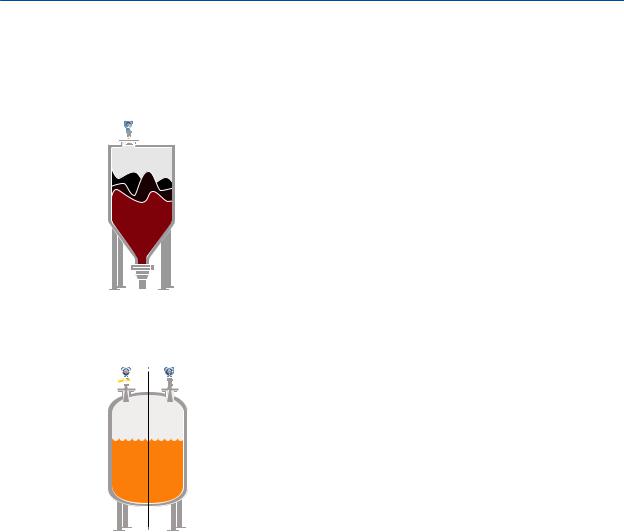
Transmitter Overview
Bulk solids
The Rosemount 5408 is the ideal solution for small to medium sized silos with rapid level changes. The narrow beam avoids internal obstructions while still keeping good level measurement.
Safety applications
The Rosemount 5408:SIS is the ideal choice for safety functions such as overfill prevention, level deviation monitoring or dry-run prevention.
SIL2 
2.5Components of the transmitter
Figure 2-3 shows the different components of the transmitter. There are different antenna types and sizes available for various applications.
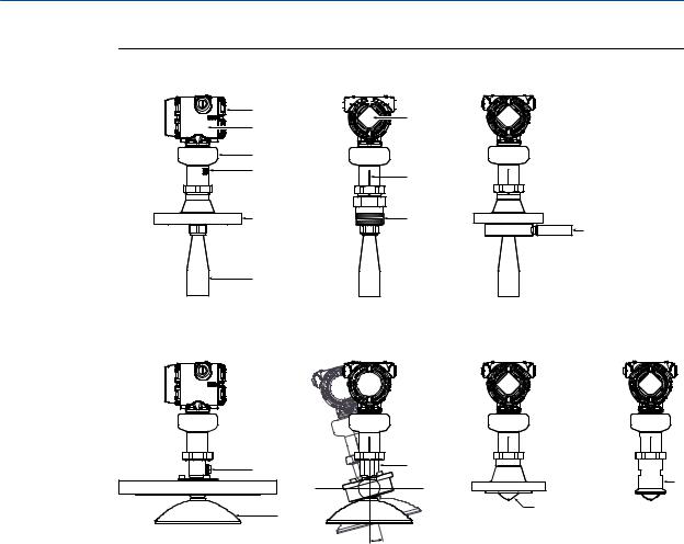
Transmitter Overview
Figure 2-3: Components
*


 *
*
+
|
/ |
1 |
|
|
3 |
||
|
0 |
2 |
|
|
s r |
|
A. |
Terminal compartment |
I. |
Alignment marker (one per side) |
|
B. |
Transmitter housing (aluminum or stainless steel) |
J. |
Threaded process connection (NPT or BSPP |
|
(G)) |
|||
|
C. |
Sensor module with signal processing electronics |
K. |
Air purge ring (option code PC1 for cone an- |
|
tenna) |
|||
|
D. |
External ground screw |
L. |
Integrated air purge connection |
|
E. |
Flanged process connection |
M. |
Parabolic antenna |
|
F. |
Cone antenna |
N. |
Parabolic antenna with swivel mount |
|
G. |
Two cable/conduit entries (½-14 NPT, M20 x 1.5, |
O. |
Process seal antenna |
|
or G½) |
|||
|
Optional adapters: eurofast™ and minifast™ |
|||
|
H. |
LCD display (optional) |
P. |
Tri-Clamp process connection |
|
Rosemount 5408 and 5408:SIS Level Transmitters |
9 |

Transmitter Overview
2.6System integration
The transmitter is loop-powered, and uses the same two wires for power supply and output signal. The output is a 4-20 mA analog signal superimposed with a digital HART signal. The transmitter can be configured for either HART Revision 6 (default) or 7 (option code HR7). The HART Revision can be switched in field.
By using the optional Rosemount 333 HART Tri-Loop™, the digital HART signal can be converted into three additional 4-20 mA analog signals. With the HART protocol, multidrop configuration is possible. In this case, communication is restricted to digital, since current is fixed to the 4 mA minimum value.
The transmitter can be combined with the Emerson™ Wireless 775 THUM™ Adapter to wirelessly communicate HART data with IEC 62591 (WirelessHART®) technology. In addition, the transmitter can be connected to a Rosemount 751 Field Signal Indicator, or it can be equipped with an LCD display.
The transmitter can easily be configured by using a PC with the Rosemount Radar Master Plus software (running in the Instrument Inspector™ Application), a Field Communicator, the AMS Device Manager, or any other Device Descriptor (DD) or Field Device Integration (FDI) compatible host system.
The Rosemount 5408 and 5408:SIS are compliant with NAMUR NE 107 Field Diagnostics for standardized device diagnostic information.
![]()
Transmitter Overview
Figure 2-4: System Architecture
)
(
&
*
,
A.Emerson Wireless 775 THUM Adapter
B.Rosemount 5408
C.Rosemount 751
D.Field Communicator
E.Approved IS barrier (for Intrinsically Safe installations only)
F.Rosemount 333
G.Host/DCS system
H.HART modem
I.Rosemount Radar Master Plus or AMS Device Manager
|
Rosemount 5408 and 5408:SIS Level Transmitters |
11 |

Transmitter Overview

Mechanical Installation
3 Mechanical Installation
3.1Safety messages
Instructions and procedures in this section may require special precautions to ensure the safety of the personnel performing the operations. Information that potentially raises safety issues is indicated by a warning symbol ( ). Refer to the following safety messages before performing an operation preceded by this symbol.
 WARNING!
Failure to follow safe installation and servicing guidelines could result in death or serious injury.
•Make sure the transmitter is installed by qualified personnel and in accordance with applicable code of practice.
•Use the equipment only as specified in this manual. Failure to do so may impair the protection provided by the equipment.
•For installations in hazardous locations, the transmitter must be installed according to the Rosemount 5408 and 5408:SIS Product Certifications document and System Control Drawing (D7000002-885).
Process leaks could result in death or serious injury.
•Make sure that the transmitter is handled carefully. If the process seal is damaged, gas might escape from the tank.
Explosions could result in death or serious injury.
•Verify that the operating atmosphere of the transmitter is consistent with the appropriate hazardous locations certifications.
3.2Confirm approval type
For hazardous locations transmitters labeled with multiple approval types:
Permanently mark the checkbox of the selected approval type(s).
|
Rosemount 5408 and 5408:SIS Level Transmitters |
13 |

Mechanical Installation
Figure 3-1: Label with Multiple Approval Types
3.3Installation considerations
Before installing the transmitter, follow recommendations for mounting position, sufficient free space, nozzle requirements, etc.
3.3.1Mounting position
When finding an appropriate location on the tank for the transmitter, the conditions of the tank must be carefully considered.
Consider the following guidelines when mounting the transmitter:
•For optimal performance, the transmitter should be installed in locations with a clear and unobstructed view of the product surface.
•The transmitter should be mounted with as few internal structures as possible within the signal beam, see Section 3.3.6.
•Do not install the transmitter in the center of the tank.
•Do not mount close to or above the inlet stream.
•Multiple Rosemount 5408 and 5408:SIS Level Transmitters can be used in the same tank without interfering with each other.
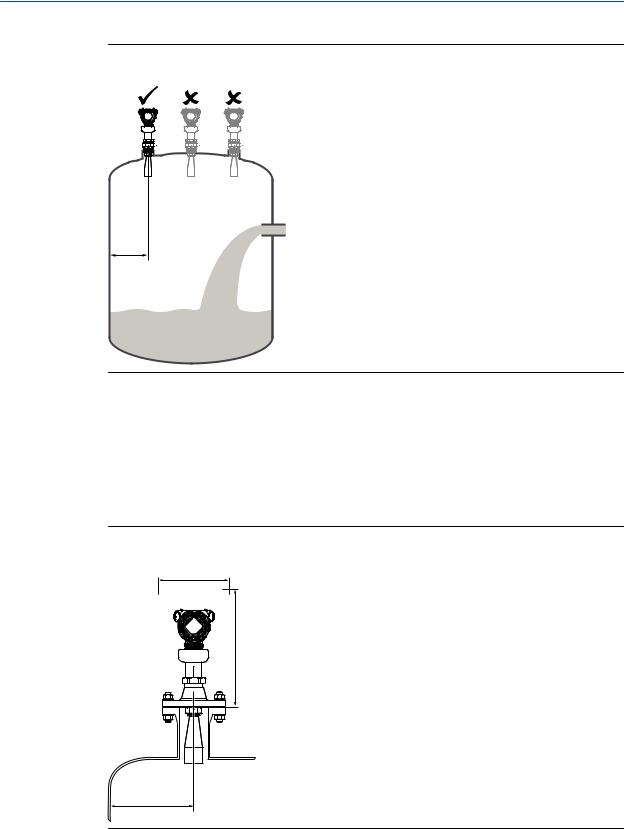
Mechanical Installation
Figure 3-2: Recommended Mounting Position
/
3.3.2Free space requirements
If the transmitter is mounted close to a wall or other tank obstructions such as heating coils and ladders, noise might appear in the measurement signal. Therefore the following minimum clearance, according to Table 3-1, must be maintained.
For easy access to the transmitter, mount it with sufficient service space (see Table 3-2).
Figure 3-3: Free Space Requirements
|
Rosemount 5408 and 5408:SIS Level Transmitters |
15 |

Mechanical Installation
Table 3-1: Distance to Tank Wall (L)
|
Application |
Minimum |
Recommended |
|
Liquids |
8 in. (200 mm) |
½ of tank radius |
|
Solids |
8 in. (200 mm) |
⅔ of tank radius |
Table 3-2: Free Space Requirements
|
Description |
Distance |
|
Service space width (A) |
20 in. (500 mm) |
|
Service space height (B) |
24 in. (600 mm) |
3.3.3Antenna size
Choose as large antenna diameter as possible. A larger antenna diameter concentrates the radar beam and ensures maximum antenna gain. Increased antenna gain permits greater margin for weak surface echoes.
In addition, a larger antenna diameter results in a smaller beam angle and thereby, less interference from any internal structures in the tank.
3.3.4Antenna inclination
Ensure the antenna is aligned perpendicular to the product surface (see Figure 3-4). The parabolic antenna comes with a swivel connection that adjusts for angled tank roofs.
Note that if the surface echo is weak in solids applications, then a small inclination of the parabolic antenna toward the surface slope may improve the performance.

Mechanical Installation
Figure 3-4: Inclination
A.Cone antenna/process seal antenna
B.Parabolic antenna
3.3.5Non-metallic tanks
The walls in non-metallic tanks can be invisible to the radar signal, so nearby objects outside the tank may cause disturbing radar echoes. Wherever possible, the transmitter should be positioned so that objects close to the tank are kept outside the signal beam.
3.3.6Beam width and beam angle
The transmitter should be mounted with as few internal structures as possible within the signal beam. Refer to Table 3-3 for beam angle and Table 3-4 for beam width at different distances.
|
Rosemount 5408 and 5408:SIS Level Transmitters |
17 |
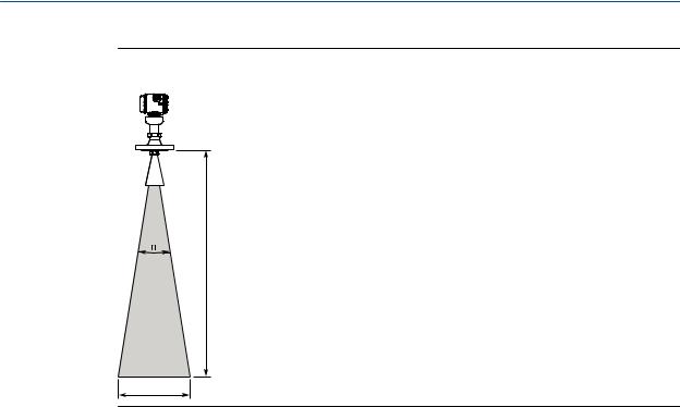
Mechanical Installation
Figure 3-5: Beam Angle and Beam Width
:
Table 3-3: Beam Angle
|
Antenna size |
Beam angle (α) |
|
2-in. (DN50) cone/process seal |
18° |
|
3-in. (DN80) cone/process seal |
14° |
|
4-in. (DN100) cone/process seal |
10° |
|
8-in. (DN200) parabolic |
4.5° |
Table 3-4: Beam Width, ft. (m)
|
Beam width (W) |
||||||
|
2-in. cone/ process |
3-in. cone/ process |
4-in. cone/ process |
||||
|
Distance (D) |
seal |
seal |
seal |
Parabolic |
||
|
16 |
(5) |
5.2 (1.6) |
4.0 (1.2) |
2.9 (0.9) |
1.3 (0.4) |
|
|
33 |
(10) |
10.4 |
(3.2) |
8.1 (2.5) |
5.7 (1.8) |
2.6 (0.8) |
|
49 |
(15) |
15.6 |
(4.8) |
12.1 (3.7) |
8.6 (2.6) |
3.9 (1.2) |
|
66 |
(20) |
20.8 |
(6.3) |
16.1 (4.9) |
11.5 (3.5) |
5.2 (1.6) |
|
82 |
(25) |
26.0 |
(7.9) |
20.1 (6.1) |
14.3 (4.4) |
6.4 (2.0) |
|
98 |
(30) |
31.2 |
(9.5) |
24.2 (7.4) |
17.2 (5.3) |
7.7 (2.4) |
|
131 (40) |
41.6 |
(12.7) |
32.2 (9.8) |
23.0 (7.0) |
10.3 (3.1) |
|

Mechanical Installation
3.3.7Nozzle requirements
In order to allow the microwaves to propagate undisturbed, the nozzle dimensions should be kept within the specified limits as given in Table 3-5, Table 3-6, and Table 3-7.
Nozzle requirements for cone antenna
For best performance, the cone antenna should extend at least 0.4 in. (10 mm) below the nozzle. If required, use the extended cone antenna versions (option code S1 or S2).
However, the antenna can be recessed in smooth nozzles up to 4 ft. (1.2 m). Note that if the inside of the nozzle has irregularities (e.g. due to bad welding, rust, or deposit), then use the extend cone antenna.
Figure 3-6: Mounting of the Cone Antenna
H


 > 0.4 in. (10 mm)
 D
D 
Table 3-5: Nozzle Requirements for Cone Antenna, in Inches (Millimeters)
|
Recommended maximum nozzle height (H)(2)(3) |
|||
|
Antenna size |
Minimum nozzle diameter (D)(1) |
Antenna |
Antenna with air purge ring (code PC1) |
|
2-in. (DN50) |
1.94 (49.3) |
5.71 (145) |
4.69 (119) |
|
3-in. (DN80) |
2.80 (71.0) |
5.63 (143) |
4.61 (117) |
|
4-in. (DN100) |
3.78 (96.0) |
6.54 (166) |
5.51 (140) |
(1)The antennas are sized to fit within schedule 80 or lower schedules.
(2)The values are valid for cone antennas without antenna extension.
(3)For liquid applications, the cone antenna can be recessed in smooth nozzles up to 4 ft. (1.2 m), but note that the accuracy may be reduced in the region close to the nozzle.
Nozzle requirements for process seal antenna
The antenna can be used on nozzles up to 4 ft. (1.2 m). Disturbing objects inside the nozzle may impact the measurement, and should therefore be avoided.
|
Rosemount 5408 and 5408:SIS Level Transmitters |
19 |

Mechanical Installation
Figure 3-7: Mounting of the Process Seal Antenna
Table 3-6: Nozzle Requirements for Process Seal Antenna
|
Recommended maximum nozzle height |
||
|
Antenna size |
Minimum nozzle diameter (D)(1) |
(H)(2) |
|
2-in. (DN50) |
1.77 in. (45 mm) |
4 ft. (1.2 m) |
|
3-in. (DN80) |
2.76 in. (70 mm) |
4 ft. (1.2 m) |
|
4-in. (DN100) |
2.76 in. (70 mm) |
4 ft. (1.2 m) |
(1)The antennas are sized to fit within schedule 120 or lower schedules.
(2)For hygienic applications, the nozzle height (H) must not exceed 2 × nozzle diameter (D) to ensure cleanability. Maximum nozzle height is 5 in. (127 mm).
Nozzle requirements for parabolic antenna
See Table 3-7 for nozzle height recommendations at different inclination angle.
![]()
Mechanical Installation
Figure 3-8: Mounting of the Parabolic Antenna
|
A |
B |
||||||||||||
A.Nozzle mounting
B.Flange mounting in manhole cover
Table 3-7: Nozzle Requirements for Parabolic Antenna, in Inches (Millimeters)
|
Nozzle size (D) |
Inclination angle (α) |
Maximum nozzle height (H)(1) |
|
|
Pipe schedule std, Ø 8 in. (200 mm) |
0° |
5.9 |
(150) |
|
3° |
5.5 |
(140) |
|
|
6° |
1.6 |
(40) |
|
|
9° |
1.2 |
(30) |
|
|
12° |
1.0 |
(25) |
|
|
15° |
0.6 |
(15) |
|
|
Pipe schedule std, Ø10 in. (250 mm) |
0° |
8.0 |
(200) |
|
3° |
8.0 |
(200) |
|
|
6° |
8.0 |
(200) |
|
|
9° |
8.0 |
(200) |
|
|
12° |
5.9 |
(150) |
|
|
15° |
4.3 |
(110) |
|
(1)Note that the inside of the nozzle must be smooth (i.e. avoid bad welding, rust, or deposit).
3.3.8Still pipe/chamber installations
Installation in still pipe/chamber is recommended for tanks where there are excessive foaming or turbulence. Still pipe/chamber may also be used to avoid disturbing objects in the tank.
Still pipe
Consider the following still pipe requirements:
|
Rosemount 5408 and 5408:SIS Level Transmitters |
21 |

Mechanical Installation
|
Pipe |
• |
Pipes should be an all-metal material. |
|
• |
Pipe should have a constant inside diameter. |
|
|
• |
The inner surface must be smooth and clear of any rough edges. |
|
|
(Smooth pipe joints are acceptable, but may reduce accuracy.) |
||
|
• |
The end of the pipe must extend beyond the zero level. |
|
|
Holes |
• |
Maximum hole diameter is 1 in. (25 mm). |
|
• |
Minimum distance between holes is 6 in. (150 mm). |
|
|
• |
Holes should be drilled on one side only and deburred. |
|
|
• |
Drill one hole above maximum product surface. |
|
|
Antenna |
• |
All cone/process seal antenna sizes can be used for still pipe/chamber |
|
installations. |
||
|
• |
The gap between the cone antenna and the still pipe should be |
|
|
maximum 0.2 in. (5 mm). If required, order a larger antenna and cut on |
||
|
location. See Table A-19 for antenna dimensions. |

Mechanical Installation
Figure 3-9: Still Pipe Requirements
‘
(
&
)
A.Max. 0.2 in. (5 mm)
B.Max. 1 in. (25 mm)
C.Min. 6 in. (150 mm)
D.Max. 1°
E.Level = 100%
F.Level = 0%
Chamber
Consider the following chamber requirements:
•Pipes should be an all-metal material.
•Pipe should have a constant inside diameter.
•Inlet pipes should not protrude into the inside of the stand pipe.
•The inner surface must be smooth and clear of any rough edges. (Smooth pipe joints are acceptable, but may reduce accuracy.)
•The gap between the cone antenna and the stand pipe should be maximum 0.2 in. (5 mm). If required, order a larger antenna and cut on location. See Table A-19 for antenna dimensions.
|
Rosemount 5408 and 5408:SIS Level Transmitters |
23 |

Mechanical Installation
Figure 3-10: Chamber Requirements
‘
&
A.Min. 0.4 in. (10 mm)
B.Min. 6 in. (150 mm)
C.Max. 1°
D.Max. 0.2 in. (5 mm)
For more information and installation requirements, refer to the Guidelines for Choosing and Installing Radar in Stilling Wells and Bypass Chambers Technical Note.
3.3.9Ball valve installation
The transmitter can be isolated from the process by using a valve:
•Use a full-port ball valve.
•Ensure there is no edge between the ball valve and the nozzle or still pipe, the inside should be smooth.
•Valves can be combined with still pipes.

Mechanical Installation
3.4Mounting preparations
3.4.1Assemble the segmented cone antenna
This section applies to the segmented cone antenna (option code S2). Use only one segment; the total antenna length should not exceed 47.2 in. (1200 mm).
To determine the antenna length, follow the guidelines in section Section 3.3.7.
Procedure
1.Insert the segment into the cone antenna until it bottoms.
2.Mark where to cut the segment.
|
0 |
1 |
2 |
3 |
4 |
5 |
6 |
7 |
8 |
9 |
|||||||
3.Remove and cut the segment at the marking.
4.Remove any burrs.
5.Insert the segment into the cone antenna until it bottoms.
6.Secure the segment to the antenna.
|
Rosemount 5408 and 5408:SIS Level Transmitters |
25 |

Mechanical Installation
7.Measure the Antenna Extension Length (L).
|
0 |
1 |
2 |
3 |
4 |
5 |
6 |
7 |
8 |
9 |
/
8.Update the transmitter configuration to the new Antenna Extension Length (L).
•Rosemount Radar Master Plus:
—Under Configure, select Level Setup > Antenna.
•AMS Device Manager and Field Communicator:
—Select Configure > Manual Setup > Level Setup > Antenna.
3.4.2Shorten the extended cone antenna
This section only applies to the extended cone antenna (option code S1).
To determine the antenna length, follow the guidelines in section Section 3.3.7.
Procedure
1.Mark where to cut the antenna.
|
0 |
1 |
2 |
3 |
4 |
5 |
6 |
||||||
2.Cut the antenna at the marking.

Mechanical Installation
3.Remove any burrs.
4.Measure the Antenna Extension Length (L).
|
0 |
1 |
2 |
3 |
4 |
5 |
6 |
/
5.Update the transmitter configuration to the new Antenna Extension Length (L).
•Rosemount Radar Master Plus:
—Under Configure, select Level Setup > Antenna.
•AMS Device Manager and Field Communicator:
—Select Configure > Manual Setup > Level Setup > Antenna.
|
Rosemount 5408 and 5408:SIS Level Transmitters |
27 |

Mechanical Installation
3.5Mount the cone antenna
Figure 3-11: Overview
|
& |
‘ |
( |
||||||||||||||||||||||||||
‘
‘
A.Flanged version (see page 29)
B.Flanged version with air purge ring (see page 30)
C.Threaded version, D < d (see page 31)
D.Threaded version, D > d (see page 34)
E.Bracket mounting (see page 36)
3.5.1Protective cap
For spare antennas, keep the protective cap in place until installing the transmitter head. The cap protects the process seal from dust and water.

Mechanical Installation
Figure 3-12: Protective Cap
3.5.2Flanged version
1.If applicable, assemble the segmented cone antenna (see Section 3.4.1).
2.Lower transmitter with antenna and flange into the nozzle.

 Gasket
3.Tighten bolts and nuts with sufficient torque for the flange and gasket choice.
4.Align the transmitter head (see Section 3.5.7).
|
Rosemount 5408 and 5408:SIS Level Transmitters |
29 |

Mechanical Installation
3.5.3Flanged version with air purge ring (option code PC1)
1.If applicable, assemble the segmented cone antenna (see Section 3.4.1).
2.Place a suitable gasket on the tank flange.
3.Place the purge ring over the gasket.
4.Place a suitable gasket over the purge ring.
Note
A minimum gasket thickness of 0.125 in. (3.2 mm) is required for flanges with protective plate design.
5.Lower transmitter with antenna and flange into the nozzle.
Antenna with air purge holes
6.Tighten bolts and nuts with sufficient torque for the flange and gasket choice.
![]()
Mechanical Installation
1.0 in. (25.5 mm)

7.Connect the air purging system. Use thread sealant or suitable gasket according to your site procedures.
or
Table 3-8: Incoming Air Supply Specification
|
Maximum pressure |
Recommended pressure |
|
190 psi (13 bar) |
100 to 115 psi (7 to 8 bar) |
8. Align the transmitter head (see Section 3.5.7).
3.5.4Threaded version, antenna diameter (D) < Thread diameter (d)
Flanged tank connection
1.If applicable, assemble the segmented cone antenna (see Section 3.4.1).
|
Rosemount 5408 and 5408:SIS Level Transmitters |
31 |

Mechanical Installation
2.Place a suitable gasket on the tank flange.
3.Place the customer supplied flange over the gasket.
4.Tighten the bolts and nuts with sufficient torque for the flange and gasket choice.
5.Apply anti-seize paste or PTFE tape on threads according to your site procedures.
 Gasket may be used as a sealant for adapters with 1½or 2-in. BSPP (G) threads.
6.Lower transmitter with antenna and flange into the nozzle.

Mechanical Installation
Gasket
(for 1½-in. and 2-in. BSPP (G) threads only)
7.Align the transmitter head (see Section 3.5.7).
Threaded tank connection
1.If applicable, assemble the segmented cone antenna (see Section 3.4.1).
2.Apply anti-seize paste or PTFE tape on threads according to your site procedures.
 Gasket may be used as a sealant for adapters with 1½or 2-in. BSPP (G) threads.
3.Mount the transmitter on the tank.
|
Rosemount 5408 and 5408:SIS Level Transmitters |
33 |

Mechanical Installation
Gasket
(for 1½-in. and 2-in. BSPP (G) threads only)
4.Align the transmitter head (see Section 3.5.7).
3.5.5Threaded version, antenna diameter (D) > Thread diameter (d)
1.If applicable, assemble the segmented cone antenna (see Section 3.4.1).
2.Unscrew and remove the antenna.


 H2 mm
H2 mm
Note
Be careful not to scratch the microwave launcher. The microwave launcher is sensitive to mechanical impacts.
Microwave launcher

Mechanical Installation
3.Apply anti-seize paste or PTFE tape on threads according to your site procedures.
 Gasket may be used as a sealant for adapters with 1½or 2-in. BSPP (G) threads.
4.Mount the adapter on the customer supplied flange.
Gasket
(for 1½-in. and 2-in. BSPP (G) threads only)
5.Mount the antenna.
 Torque 5 in-lb (0.5 N-m)
H2 mm
 Torque 250 in-lb (28 N-m) 38 mm
Note
Visually inspect the microwave launcher for damage and dirt.
6.Lower transmitter with antenna and flange into the nozzle.
|
Rosemount 5408 and 5408:SIS Level Transmitters |
35 |

Mechanical Installation

 Gasket
7.Tighten the bolts and nuts with sufficient torque for the flange and gasket choice.
8.Screw the adapter until it is properly tightened.
9.Align the transmitter head (see Section 3.5.7).
3.5.6Bracket mounting
1.Mount the bracket to the pipe/wall. On pipe:

Mechanical Installation
Horizontal pipe
4X
Vertical pipe
On wall:
4X
2.Mount the holder to the bracket.
3.Unscrew and remove the antenna.


 H2 mm
H2 mm
Note
Be careful not to scratch the microwave launcher. The microwave launcher is sensitive to mechanical impacts.
|
Rosemount 5408 and 5408:SIS Level Transmitters |
37 |

Mechanical Installation
Microwave launcher
4.Screw the transmitter into the holder.
5.Mount the antenna.
 Torque 5 in-lb (0.5 N-m)
H2 mm
38mm
6.Align the transmitter head (see Section 3.5.7).
3.5.7Align transmitter head
1.Loosen the nut slightly and turn the transmitter.

Mechanical Installation
60 mm
2.Verify the transmitter head is properly aligned.
|
Option |
Description |
|
Open tank |
Align the marking on the sensor module toward the tank wall (see Figure 3-13). |
|
Still pipe |
Align the external ground screw toward the holes of the still pipe (see |
|
Figure 3-14). |
|
|
Chamber |
Align the external ground screw toward the process connections (see |
|
Figure 3-15). |
|
3.Tighten the nut.
 Torque 355 in-lb (40 N-m) 60 mm
Figure 3-13: Open Tank
|
Rosemount 5408 and 5408:SIS Level Transmitters |
39 |

Mechanical Installation
Figure 3-14: Still pipe
Figure 3-15: Chamber
3.6Mount the process seal antenna
Figure 3-16: Overview
A.Flanged version (see page 40)
B.Tri-Clamp version (see page 42)
3.6.1Flanged version
1.Lower the transmitter into the nozzle.
 Loading…
Quick Start Manual for Emerson Rosemount 5408 Measuring Instruments, Transmitter (36 pages)
File Specifications:1300/1300280-rosemount_5408.pdf file (13 Jul 2023) |
Accompanying Data:
Emerson Rosemount 5408 Measuring Instruments, Transmitter PDF Quick Start Manual (Updated: Thursday 13th of July 2023 05:08:07 PM)
Rating: 4.4 (rated by 95 users)
Compatible devices: Micro Motion 7829 Visconic Series, ROSEMOUNT 5300, Rosemount 326P, Rosemount CT5400, Rosemount 2410, Rosemount 2555, Rosemount 370XA, PENBERTHY LC Series.
Recommended Documentation:
Quick Start Manual (Text Version):
(Ocr-Read Summary of Contents of some pages of the Emerson Rosemount 5408 Document (Main Content), UPD: 13 July 2023)
-
22, Emerson Rosemount 5408 6.8 Wiring diagram Figure 6-4: 4-20 mA/HART ® Communication & % ( ) ‘ $ A. Handheld communicator B. Approved IS barrier (for Intrinsically Safe installations only) C. HART modem D. Load resistance (≥250 Ω) E. Current meter F. Power supply Quick Start Guide June 2019 22 Rosemount 5408 and 5408:SIS Level Transmitters
… -
17, Emerson Rosemount 5408 Figure 4-1: Open Tank Figure 4-2: Still pipe Figure 4-3: Chamber June 2019 Quick Start Guide Quick Start Guide 17
… -
36, *00825-0100-4408* Quick Start Guide 00825-0100-4408, Rev. BB June 2019 Global Headquarters Emerson Automation Solutions 6021 Innovation Blvd. Shakopee, MN 55379, USA +1 800 999 9307 or +1 952 906 8888 +1 952 949 7001 [email protected] North America Regional Office Emerson Automation Solutions 8200 Market Blvd. Chanhassen, MN 55317, USA +1 800 999 9307 or +1 952 906 8888 +1 952 949 7001 [email protected] Latin America Regional Office Emers…
-
2, Contents About this guide……………………………………………………………………………………………………………3 Confirm approval type……………………………………………………………………………………………………5 Mount the transmitter……………………………………………………………………………………………………6 Align …
-
9, 3.3 Threaded version, antenna diameter smaller than thread diameter 3.3.1 Threaded tank connection Prerequisites If applicable, assemble the segmented cone antenna (see Assemble the segmented cone antenna). Procedure 1. Apply anti-seize paste or PTFE tape on threads according to your site procedures. Gasket may be used as a sealant for adapters with 1½- or 2-in. BSPP (G) threads. 2. Mount the transmitter on the tank. $ A. Gasket (for 1½-in. and 2-in. BSPP (G) threads only) June 2019 Quick S…
-
28, Emerson Rosemount 5408 9. Attach and tighten the cover. a) Verify the cover jam screw is completely threaded into the housing. H2.5 mm b) Attach and tighten the cover. Make sure the cover is fully engaged. There should be no gap between the cover and the housing. c) Turn the jam screw counterclockwise until it contacts the cover. Required for explosion-proof/flameproof installations only. Quick Start Guide June 2019 28 Rosemount 5408 and 5408:SIS Level Transmitters
… -
32, 9 Assemble the segmented cone antenna This section applies to the segmented cone antenna (option code S2). Use only one segment; the total antenna length should not exceed 47.2 in. (1200 mm). Figure 9-1: Installation Recommendation $ A. Min. 0.4 in. (10 mm) Procedure 1. Insert the segment into the cone antenna until it bottoms. 2. Mark where to cut the segment. 1 2 3 4 5 6 7 8 0 9 3. Remove and cut the segment at the marking. 4. Remove any burrs. 5. Insert the se…
-
27, 5. Connect the cable wires (see Wiring diagram). Torque 7 in-lb (0.8 N-m) 6. Ensure proper grounding (see Grounding). 7. Tighten the cable gland. Apply PTFE tape or other sealant to the threads. Note Make sure to arrange the wiring with a drip loop. 8. Seal any unused ports with the enclosed metal plug. Apply PTFE tape or other sealant to the threads. June 2019 Quick Start Guide Quick Start Guide 27
… -
15, Note Be careful not to scratch the microwave launcher. The microwave launcher is sensitive to mechanical impacts. 4. Screw the transmitter into the holder. 5. Mount the antenna. H2 mm 38 mm Torque 5 in-lb (0.5 N-m) Postrequisites Align the transmitter head (see Align transmitter head). June 2019 Quick Start Guide Quick Start Guide 15
… -
7, 3.2 Flanged version with air purge ring (option code PC1) Prerequisites If applicable, assemble the segmented cone antenna (see Assemble the segmented cone antenna). Procedure 1. Place a suitable gasket on the tank flange. 2. Place the purge ring over the gasket. 3. Place a suitable gasket over the purge ring. Note A minimum gasket thickness of 0.125 in. (3.2 mm) is required for flanges with protective plate design. 4. Lower transmitter with antenna and flange into the nozzle. $ A. Antenna wit…
-
33, 6. Secure the segment to the antenna. Note Be careful of sharp edges. Wear protective gloves! 1 2 3 4 7. Measure the Antenna Extension Length (L). Antenna Extension Length (L): / 1 2 3 4 5 6 7 8 0 9 8. Update the transmitter configuration to the new Antenna Extension Length (L). • Rosemount Radar Master Plus: — Under Configure, select Level Setup → Antenna. • AMS Device Manager and handheld communicator: — Select Configure �…
-
16, 4 Align transmitter head Procedure 1. Loosen the nut slightly and turn the transmitter. 60 mm 2. Verify the transmitter head is properly aligned. Option Description Open tank Align the marking on the sensor module toward the tank wall (see Figure 4-1). Still pipe Align the external ground screw toward the holes of the still pipe (see Figure 4-2). Chamber Align the external ground screw toward the process connections (see Figure 4-3). 3. Tighten the nut. 60 mm Torque 355 in-lb (4…
-
30, 8 Configure transmitter using Guided Setup 8.1 Configuration tools The transmitter can easily be configured using: • Rosemount Radar Master Plus (running in the Instrument Inspector ™ Application) • Device Descriptor (DD) based systems, e.g. AMS Device Manager, 475 Field Communicator, AMS Trex ™ Device Communicator, and DeltaV ™ , or any other EDDL or enhanced-EDDL host • Field Device Integration (FDI) based systems Rosemount Radar Master Plus is the recommended tool …
-
1, Quick Start Guide 00825-0100-4408, Rev BB June 2019 Rosemount ™ 5408 and 5408:SIS Level Transmitters Cone Antenna
… -
13, 5. Place a suitable gasket on the tank flange. 6. Lower transmitter with antenna and flange into the nozzle. 7. Tighten the bolts and nuts with sufficient torque for the flange and gasket choice. 8. Screw the adapter until it is properly tightened. Postrequisites Align the transmitter head (see Align transmitter head). June 2019 Quick Start Guide Quick Start Guide 13
… -
4, WARNING Process leaks could result in death or serious injury. • Make sure that the transmitter is handled carefully. If the process seal is damaged, gas might escape from the tank. WARNING Physical access Unauthorized personnel may potentially cause significant damage to and/or misconfiguration of end users’ equipment. This could be intentional or unintentional and needs to be protected against. Physical security is an important part of any security program and fundamenta…
-
Emerson Rosemount 5408 User Manual
-
Emerson Rosemount 5408 User Guide
-
Emerson Rosemount 5408 PDF Manual
-
Emerson Rosemount 5408 Owner’s Manuals
Recommended: CFA1300W, 1005438, HI DELTA SS HD101, PDUMNH20
Links & Tools
Operating Impressions, Questions and Answers:
-
Icom IC-A14
To : Icom Distributors From : Icom Inc., Japan Date : 21 November, 2007 Ref. No. : NPI-128 We are sending the new product information for the IC-A14/S, A15/S series handheld air band radios. You are authorized to circulate the attached information in its current form to your Dealers if you wish (Layou …
IC-A14 Transceiver, 6
-
WEVI VW-5
VW-5 取扱説明書 Operating Instructions 日本語 _________ Pages 2 — 13 English _________ Pages 14 — 29 WEVI — a division of IDX …
VW-5 Transmitter, 30
-
Pima TRV Series
-1- TRV/TRU Installation Instructions Инструкция по установке Instrucciones de Instalación הנקתה תוארוה English, Русский, Español, תירבע 1 TRV/TRU Transmitter 2 Control Panel Wiring Socket 3 F2 Connector 4 Programming Socket 5 Molex Cable 6 Control Panel 7 TRA …
TRV Series Transmitter, 8
-
JTS TG-98R
FCC StatementNotice: The changes or modifications not expressly approved by the party responsible for compliance could void the user’s authority to operate the equipment.This device complies with part 15 of the FCC Rules. Operation is subject to the following two conditions: (1) This device may not cause harmful inte …
TG-98R Transmitter, 4
-
Extron electronics FOX II T DP 4K
1 IMPORTANT:Go to www.extron.com for the complete user guide, installation instructions, and specifications before connecting the product to the power source.FOX II T/R DP 4K • Setup GuideThis guide provides quick start instructions for an experienced installer to set up and operate the Extron FOX II T/R DP 4K Fiber …
FOX II T DP 4K Extender, 4
-
Wyrestorm TX-SW-0201
HDBaseT™ 4K Transmitter with HDMI / VGA Auto-SwitchTX-SW-0201Quickstart GuideIn the Box1 x TX-SW-0201 Transmitter1 x 12V DC 1A Power Supply1 x 3-pin Screw Down Phoenix ConnectorFront PanelVGA Input 15-pin VGA VESA (D-SUB 15): Connect to D-SUB 15 VGA output of device such as a computer.HDMI Input 19-pin type …
TX-SW-0201 Transmitter, 2
-
Dräger PIR 3000
Dräger PIR 3000 – InstallationshinweisJede Handhabung an dem Gastransmitter setzt die genaue Kenntnis und Beachtung der «Gebrauchsanweisung» zum Dräger PIR 3000 (Bestell-Nr. 9023812) voraus!Gastransmitter installierenInstallation des Gastransmitters nur durch Fachleute (z. B. dem Service von Dräger Saf …
PIR 3000 Transmitter, 12
-
F-S Electronics Rangemaster X-Treme Series
F-S Electronics 2016© 1 FAIL-SAFE CONTENTS: 1- FSX-05B FM TRANSMITTER 1- GVE 12V 2.0A POWER SUPPLY 1- RUBBER DUCK ANTENNA REVERSE THREAD TNC 1- INSTRUCTION MANUAL Optional range adding accessories available at tinyurl.com/y8z4wgno: Reverse TNC Male x N-Type Female Adapter Various Broadcast Cables …
Rangemaster X-Treme Series Transmitter, 4
Руководство по быстрому старту
00825-0500-4408, ред. до н.э.
Датчики уровня Rosemount™ 5408 и 5408:SIS
Антенна с технологическим уплотнением
Об этом руководстве
В этом кратком руководстве представлены основные рекомендации по использованию уровнемеров Rosemount 5408 и 5408:SIS. См. Rosemount 5408 и 5408:SIS с HART®. Датчики уровня Rosemount 5408 и 5408:SIS (emerson.com) и Rosemount 5408 с FOUNDATION™ Fieldbus Уровнемер Rosemount 5408 (emerson.com) для получения дополнительных инструкций. Руководства и данное руководство также доступны в электронном виде на Emerson.com/Rosemount.
1.1 Сообщения о безопасности![]() ПРЕДУПРЕЖДЕНИЕ
ПРЕДУПРЕЖДЕНИЕ
Несоблюдение правил безопасной установки и обслуживания может привести к смерти или серьезной травме.
Убедитесь, что преобразователь установлен квалифицированным персоналом и в соответствии с применимыми нормами и правилами.
Используйте оборудование только так, как указано в данном руководстве. В противном случае может ухудшиться защита, обеспечиваемая оборудованием.
При установке в опасных зонах преобразователь должен быть установлен в соответствии с Rosemount 5408 и 5408:SIS. Датчики уровня Rosemount 5408 и 5408:SIS (emerson.com) документ и контрольный чертеж системы (D7000002-885).
Ремонт, например замена компонентов и т. д., может поставить под угрозу безопасность и не допускается ни при каких обстоятельствах.![]() ПРЕДУПРЕЖДЕНИЕ
ПРЕДУПРЕЖДЕНИЕ
Взрыв может привести к смерти или серьезным травмам.
Убедитесь, что рабочая атмосфера трансмиттера соответствует соответствующим сертификатам для опасных зон.
Перед подключением портативного коммуникатора во взрывоопасной среде убедитесь, что приборы установлены в соответствии с правилами искробезопасной или невоспламеняющейся полевой проводки.
Во взрывозащищенных/пожаробезопасных и невоспламеняющихся установках/установках типа n не снимайте крышки трансмиттера, когда на блок подается питание.
Обе крышки трансмиттера должны быть полностью закрыты, чтобы соответствовать требованиям взрывозащищенности/пожаробезопасности.![]() ПРЕДУПРЕЖДЕНИЕ
ПРЕДУПРЕЖДЕНИЕ
Поражение электрическим током может привести к смерти или серьезным травмам.
Во взрывозащищенных/пожаробезопасных и невоспламеняющихся установках типа n избегайте контакта с проводами и клеммами. Высокий объемtagд., которые могут присутствовать на проводах, могут привести к поражению электрическим током.
Убедитесь, что сетевое питание преобразователя отключено, а линии к любым другим внешним источникам питания отсоединены или обесточены при подключении преобразователя.![]() ПРЕДУПРЕЖДЕНИЕ
ПРЕДУПРЕЖДЕНИЕ
Утечки в процессе могут привести к смерти или серьезным травмам.
Убедитесь, что с передатчиком обращаются осторожно. Если технологическое уплотнение повреждено, газ может выйти из резервуара.![]() ПРЕДУПРЕЖДЕНИЕ
ПРЕДУПРЕЖДЕНИЕ
Физический доступ
Неуполномоченный персонал может потенциально вызвать значительный ущерб и / или неправильную настройку оборудования конечных пользователей. Это может быть преднамеренным или непреднамеренным, и от него необходимо защитить себя.
Физическая безопасность является важной частью любой программы безопасности и имеет основополагающее значение для защиты вашей системы. Ограничьте физический доступ неавторизованного персонала для защиты активов конечных пользователей. Это относится ко всем системам, используемым на объекте.![]() ВНИМАНИЕ!
ВНИМАНИЕ!
Горячие поверхности
Фланец и технологическое уплотнение могут быть горячими при высоких температурах технологического процесса. Дайте остыть перед обслуживанием. ![]()
Подтвердить тип утверждения
Датчики для опасных зон маркируются несколькими типами сертификатов:
Процедура
Постоянно отмечайте флажок выбранного типа(ов) утверждения.
Рисунок 2-1: Этикетка с несколькими типами утверждений
Установите фланцевую версию
Процедура
- Опустите передатчик в сопло.
Внимание
Будьте осторожны, чтобы не поцарапать или иным образом не повредить тефлоновое уплотнение.Внимание
Не снимайте тефлоновое уплотнение. - Затяните болты и гайки (см. Таблицу 3-1).
Внимание
• Повторно затяните через 24 часа и еще раз после первого температурного цикла.
• Регулярно проверяйте и при необходимости подтягивайте.Почтовые реквизиты
Выровняйте головку передатчика.
3.1 Характеристики крутящего момента
Условия, используемые для расчета: стандартный сопрягаемый металлический фланец, материал болта A193 B8M Cl.2 / A4-70 и коэффициент трения μ = 0.16.
Для болтов низкой прочности и неметаллических ответных фланцев может потребоваться меньший момент затяжки.
Таблица 3-1: Значения крутящего момента для антенны с технологическим уплотнением, фунт-фут (Нм)
| Размер технологического соединения | Рейтинг подключения к процессу | |||||
| ASME B16.5 | EN1092-1 | ДЖИС Б2220 | ||||
| Класс 150 | Класс 300 | PN6 | PN10 / PN16 | PN25 / PN40 | 10K | |
| 2 дюйма/DN50/50A | 29 (40) | 52 (70) | 15 (20) | 26 (35) | 29 (40) | 18 (25) |
| 3 дюйма/DN80/80A | 33 (45) | 48 (65) | 37 (50) | 37 (50) | 41 (55) | 22 (30) |
| 4 дюйма/DN100/100A | 59 (80) | 52 (70) | 37 (50) | 37 (50) | 74 (100) | 26 (35) |
Гора Три Клamp версия
Процедура
- Опустите передатчик в сопло.
Внимание
Будьте осторожны, чтобы не поцарапать или иным образом не повредить тефлоновое уплотнение. - Затяните clamp рекомендуемому крутящему моменту (см. инструкцию производителя).
Почтовые реквизиты
Выровняйте головку передатчика.
Установите кронштейн
Процедура
1. Установите кронштейн на трубу/стену.
На трубе: А. Горизонтальная труба
Б. Вертикальная труба
На стенке:
2. Установите преобразователь на кронштейн.
Выровняйте головку передатчика
Процедура
1. Слегка ослабьте гайку и поверните передатчик.
2. Убедитесь, что головка трансмиттера правильно выровнена.
| Опция | Описание |
| Открытый резервуар | Совместите маркировку на сенсорном модуле со стенкой резервуара (см. Рисунок 6-1). |
| Спокойная труба | Совместите внешний винт заземления с отверстиями успокоительной трубы (см. Рисунок 6-2). |
| камера | Совместите внешний винт заземления с технологическими соединениями (см. Рисунок 6-3). |
Рисунок 6-1: Открытый бакРисунок 6-2: Все еще труба
Рисунок 6-3: Камера
3. Затяните гайку.
Отрегулируйте ориентацию дисплея (необязательно)
Для улучшения доступа к проводке в полевых условиях или для улучшения view дополнительный ЖК-дисплей:
Предпосылки
Внимание
В приложениях с высокой вибрацией корпус преобразователя должен полностью входить в сенсорный модуль, чтобы соответствовать требованиям к испытаниям на вибрацию.
Это достигается вращением корпуса преобразователя по часовой стрелке до упора резьбы.
Процедура
- Ослабляйте установочный винт до тех пор, пока корпус преобразователя не сможет плавно вращаться.
- Сначала поверните корпус по часовой стрелке в нужное место. Если желаемое положение не может быть достигнуто из-за ограничения резьбы, поверните корпус против часовой стрелки до нужного места (до 360° от ограничения резьбы).
- Снова затяните установочный винт.
Рисунок 7-1: Поверните корпус преобразователя
Подготовьте электрические соединения
8.1 Выбор кабеля
Таблица 8-1: Рекомендуемый размер кабеля
| протокол | Диаметр проволоки |
| 4–20 мА/HART® | 24-14 AWG |
| Полевая шина FOUNDATION™ | 18 AWG, кабель Fieldbus типа A |
Витые пары и экранированная проводка рекомендуются для сред с высоким уровнем EMI (электромагнитных помех).
Используйте провод, рассчитанный как минимум на 5 °C выше максимальной температуры окружающей среды.
К каждому винтовому зажиму можно безопасно подключить два провода.
8.2 Кабельный ввод/кабелепровод
Для взрывозащищенных/пожаробезопасных установок используйте только кабельные вводы или кабельные вводы, сертифицированные как взрывозащищенные или огнестойкие.
8.3 Потребляемая мощность
Максимум. 1 Вт, ток макс. 23 мА
8.4 Заземление
Убедитесь, что заземление выполнено в соответствии с национальными и местными электротехническими нормами. В противном случае может ухудшиться защита, обеспечиваемая оборудованием.
Корпус преобразователя
Наиболее эффективным методом заземления является прямое соединение с заземлением с минимальным импедансом. Предусмотрено два винтовых соединения заземления (см. Рисунок 8-1).
Рисунок 8-1: Винты заземленияA. Внутренний винт заземления
B. Внешний винт заземления
Заземление экрана кабеля
Убедитесь, что экран кабеля прибора:
- Обрезаны вплотную и изолированы от прикосновения к корпусу преобразователя.
- Непрерывно подключен по всему сегменту.
- Подключен к надежному заземлению на стороне источника питания.
Рисунок 8-2: Экран кабеля
A. Изолируйте экран и заземляющий провод.
Б. Минимизируйте расстояние
C. Обрежьте экран и изолируйте оголенный заземляющий провод.
D. Подключите заземляющий провод к заземлению источника питания.
Внимание
Не заземляйте экран и его заземляющий провод на преобразователе. Если экран кабеля касается корпуса преобразователя, это может привести к образованию контуров заземления и помехам для связи.
8.5 Электропитание
Полевая шина 4–20 мА/HART®
Датчик работает от 12–42.4 В постоянного тока (12–30 В постоянного тока в искробезопасных установках) на клеммах датчика.
ФИСКО/ФОНД™
Преобразователь работает при напряжении 9-32 В пост. тока (9-30 В пост. тока в искробезопасных установках и 9-17.5 В пост. тока для FISCO) на клеммах преобразователя.
8.6 Завершение сигнала
Терминатор должен быть установлен в начале и в конце каждого сегмента Fieldbus.
Для передатчика со встроенным терминатором подключите перемычку между клеммами «TERMINATE ON», чтобы активировать терминатор. Рекомендуемый размер провода см. в разделе Выбор кабеля.
8.7 Ограничения по нагрузке
Для связи по протоколу HART® требуется минимальное сопротивление контура 250 Ом.
Максимальное сопротивление контура определяется объемомtagуровень внешнего питания.
Рисунок 8-3: Пределы нагрузки
Максимальное сопротивление контура = 43.5 × (объем внешнего источника питания).tagд — 12)
A. Сопротивление контура (Ом)
B. Объем внешнего источника питанияtagе (В постоянного тока)
8.8 Схема подключения
Рисунок 8-4: Связь 4-20 мА/HART®
А. Портативный коммуникатор
B. Утвержденный искробезопасный барьер (только для искробезопасных установок)
C. HART-модем
D. Сопротивление нагрузки (≥250 Ом)
E. Измеритель тока
F. Электропитание
Рисунок 8-5: Связь 4–20 мА/HART — клеммная колодка с клеммой TEST
А. Портативный коммуникатор
B. Утвержденный искробезопасный барьер (только для искробезопасных установок)
C. HART-модем
D. Сопротивление нагрузки (≥250 Ом)
E. Измеритель тока
F. Электропитание
Г. Синяя вилка
З. ТЕСТ-терминал
Внимание
Отсоединяйте синюю вилку только во время процедуры измерения тока контура.
Рисунок 8-6: Полевая шина FOUNDATION™
А. Портативный коммуникатор
B. Утвержденный искробезопасный барьер (только для искробезопасных установок)
C. Модем FOUNDATION Fieldbus
Д. Электропитание
Клеммы не чувствительны к полярности.
Рисунок 8-7: FOUNDATION Fieldbus — клеммная колодка со встроенным терминатором и соединениями для последовательного подключения
А. Танкбус
B. Экран кабеля (изолируйте от прикосновения к корпусу преобразователя)
C. Встроенный терминатор (подсоедините перемычку, если это последнее устройство в сегменте Fieldbus)
D. Последовательное подключение к другим устройствам
E. Портативный коммуникатор
F. Модем полевой шины
Г. Источник питания
H. Модуль связи Rosemount™ 2410
Подключить проводку и подать питание
Процедура
 Убедитесь, что источник питания отключен.
- Снимите крышку.
- Снимите пластиковые заглушки.
- Протяните кабель через кабельный сальник/кабелепровод. (1) Идентификация размера и типа резьбы:
(1) Если не промаркировано, вводы кабелепроводов/кабелей в корпус преобразователя имеют форму резьбы ½–14 NPT.
- Подсоедините провода кабеля.
- Обеспечьте надлежащее заземление.
- Затяните кабельный сальник.
Нанесите на резьбу тефлоновую ленту или другой герметик.Внимание
Не забудьте организовать проводку с капельной петлей. - Закройте все неиспользуемые порты прилагаемой металлической заглушкой.
Нанесите на резьбу тефлоновую ленту или другой герметик. - Установите и затяните крышку.
a) Убедитесь, что стопорный винт крышки полностью ввинчен в корпус.б) Установите и затяните крышку.
Внимание
Убедитесь, что крышка полностью зафиксирована. Между крышкой и корпусом не должно быть зазора.c) Поверните стопорный винт против часовой стрелки, пока он не коснется крышки.
Внимание
Требуется только для взрывозащищенных/пожаробезопасных установок.г) Поверните стопорный винт еще на ½ оборота против часовой стрелки, чтобы зафиксировать крышку.
- Подключите блок питания.
Внимание
Может пройти до 15 секунд, прежде чем загорится ЖК-дисплей.
Конфигурация
10.1 Инструменты настройки
- Системы на основе интеграции полевых устройств (FDI) (требуются для запуска Rosemount Radar Master Plus)
- Системы на основе дескриптора устройства (DD)
- Системы на базе Device Type Manager (DTM™)
10.2 Rosemount Radar Master Plus
Rosemount Radar Master Plus — это удобный программный пакет, который включает в себя базовые параметры конфигурации, а также расширенные функции настройки и обслуживания.
Для настройки рекомендуется использовать Rosemount Radar Master Plus.
Для запуска Rosemount Radar Master Plus требуется приложение AMS Instrument Inspector или любой хост, совместимый с FDI.
Связанная информация
Emerson.com/RosemountRadarMasterPlus
10.2.1 Загрузка AMS Instrument Inspector
Предпосылки
Смотрите пост в Инспектор инструментов AMS | Эмерсон США для получения списка поддерживаемых модемов и системных требований.
Процедура
Загрузите программное обеспечение на Emerson.com/InstrumentInspector.
10.2.2 Сообщение об ошибке Radar Master
Если появляется сообщение об ошибке «Не удается инициализировать Radar Master», это означает, что версия программного обеспечения на вашем устройстве требует обновления пакета FDI Rosemount Radar Master Plus.
10.3 Подтвердите правильный драйвер устройства
Процедура
- Убедитесь, что в ваших системах загружен правильный пакет FDI/DD/DTM, чтобы обеспечить правильную связь.
- Загрузите последний пакет FDI/DD/DTM по адресу Emerson.com/DeviceInstallKits or FieldCommGroup.org.
10.4 Конфигурирование преобразователя с помощью пошаговой настройки
Параметры, доступные в мастере пошаговой настройки, включают все элементы, необходимые для основных операций.
Процедура
- Если вы используете программное обеспечение, совместимое с FDI, выберите Болееview → Rosemount Radar Master Plus.
- Выберите Настройка → Пошаговая настройка и следуйте инструкциям на экране.
Руководство по быстрому старту
00825-0500-4408, ред. до н.э.
Апрель 2022
© 2022 Emerson. Все права защищены.
Условия продажи Emerson доступны по запросу. Логотип Emerson является товарным знаком и знаком обслуживания Emerson Electric Co. Rosemount является товарным знаком одной из компаний семейства Emerson. Все остальные товарные знаки являются собственностью их владельцев.
Датчики уровня Rosemount 5408 и 5408:SIS