
-
Contents
-
Table of Contents
-
Bookmarks
Quick Links
®
Relion
670 series
Transformer protection RET670
Customized
Product Guide
Related Manuals for ABB RET670
Summary of Contents for ABB RET670
-
Page 1
® Relion 670 series Transformer protection RET670 Customized Product Guide… -
Page 2: Table Of Contents
22. Ordering…………..93 Disclaimer The information in this document is subject to change without notice and should not be construed as a commitment by ABB. ABB assumes no responsibility for any errors that may appear in this document. © Copyright 2012 ABB.
-
Page 3: Application
Since optionally be made directional and/or voltage RET670 has very low requirements on the main controlled, provide further alternative backup CTs, no interposing CTs are required.It is suitable protection. Thermal overload with two time-…
-
Page 4: Available Functions
Transformer protection RET670 1MRK 504 117-BEN D Customized Product version: 1.2 2. Available functions Main protection functions = number of basic instances = option quantities IEC 61850 ANSI Function description Transformer RET670 Differential protection T2WPDIF Transformer differential protection, two winding…
-
Page 5: Current Protection
Transformer protection RET670 1MRK 504 117-BEN D Customized Product version: 1.2 Back-up protection functions IEC 61850 ANSI Function description Transformer RET670 Current protection PHPIOC Instantaneous phase overcurrent protection OC4PTOC 51_67 Four step phase overcurrent protection EFPIOC Instantaneous residual overcurrent protection…
-
Page 6: Secondary System Supervision
Transformer protection RET670 1MRK 504 117-BEN D Customized Product version: 1.2 Control and monitoring functions IEC 61850 ANSI Function description Transformer RET670 Control SESRSYN Synchrocheck, energizing check and synchronizing 0-6, 0-5 APC30 Apparatus control for up to 6 bays, max 30 apparatuses (6CBs) incl.
-
Page 7: Monitoring
Transformer protection RET670 1MRK 504 117-BEN D Customized Product version: 1.2 IEC 61850 ANSI Function description Transformer RET670 IB16FVCB Integer to Boolean 16 conversion with Logic Node representation Monitoring CVMMXN Measurements CNTGGIO Event counter Event Event function DRPRDRE Disturbance report…
-
Page 8
Transformer protection RET670 1MRK 504 117-BEN D Customized Product version: 1.2 Designed to communicate IEC 61850 ANSI Function description Transformer RET670 Station communication SPA communication protocol LON communication protocol IEC60870-5-103 communication protocol 20/1 Operation selection between SPA and IEC60870-5-103 for SLM DNP3.0 for TCP/IP and EIA-485 communication protocol… -
Page 9: Basic Ied Functions
Transformer protection RET670 1MRK 504 117-BEN D Customized Product version: 1.2 Basic IED functions IEC 61850 Function description Basic functions included in all products IntErrorSig Self supervision with internal event list TIME Time and synchronization error TimeSynch Time synchronization ActiveGroup…
-
Page 10
Transformer protection RET670 1MRK 504 117-BEN D Customized Product version: 1.2 Two-winding applications three-winding power transformer with two two-winding power circuit breakers and transformer two CT-sets on one xx05000048.vsd side IEC05000048 V1 EN xx05000053.vsd two-winding power IEC05000053 V1 EN transformer with… -
Page 11
Transformer protection RET670 1MRK 504 117-BEN D Customized Product version: 1.2 and a voltage dependent resistor which are mounted externally connected to the IED. HZPDIF can be used to protect tee-feeders or busbars. Six single phase function blocks are available to allow application for two three-phase zones busbar protection. -
Page 12
Transformer protection RET670 1MRK 504 117-BEN D Customized Product version: 1.2 encroachment, which gives the possibility to enlarge the resistive setting of both the phase selection and the measuring zones without interfering with the load. Forward operation The extensive output signals from the phase… -
Page 13
Transformer protection RET670 1MRK 504 117-BEN D Customized Product version: 1.2 The distance protection zones can operate, enlarge the resistive setting of the measuring independent of each other, in directional (forward zones without interfering with the load. or reverse) or non-directional mode. This makes… -
Page 14
Transformer protection RET670 1MRK 504 117-BEN D Customized Product version: 1.2 encroachment, which gives the possibility to 5. Current protection enlarge the resistive setting of both the phase Instantaneous phase overcurrent protection selection and the measuring zones without PHPIOC interfering with the load. -
Page 15
Transformer protection RET670 1MRK 504 117-BEN D Customized Product version: 1.2 IDir, UPol and IPol can be independently selected protected circuit to operate closer to the thermal to be either zero sequence or negative sequence. limits. Second harmonic blocking can be set individually The three-phase current measuring protection for each step. -
Page 16
Transformer protection RET670 1MRK 504 117-BEN D Customized Product version: 1.2 one phase plus the residual current start. This Capacitor bank protection (CBPGAPC) gives a higher security to the back-up trip Shunt Capacitor Banks (SCB) are used in a power command. -
Page 17
Transformer protection RET670 1MRK 504 117-BEN D Customized Product version: 1.2 for negative sequence currents down to the Reset delay ensures operation for intermittent continuous capability of a generator. earth faults. A separate output is available as an alarm feature… -
Page 18
Transformer protection RET670 1MRK 504 117-BEN D Customized Product version: 1.2 detection of high fundamental power system voltage and/or current controlled/restrained. 2nd frequency is needed. harmonic restraining facility is available as well. At too low polarizing voltage the overcurrent feature… -
Page 19
Transformer protection RET670 1MRK 504 117-BEN D Customized Product version: 1.2 The fuse failure supervision function basically has SESRSYN function includes a built-in voltage three different algorithms, negative sequence and selection scheme for double bus and 1½ breaker zero sequence based algorithms and an or ring busbar arrangements. -
Page 20
Transformer protection RET670 1MRK 504 117-BEN D Customized Product version: 1.2 supervised. Enhanced security means that the switches are used extensively by utilities, in order command is evaluated with an additional to have different functions operating on pre-set supervision of the status value of the control values. -
Page 21
Transformer protection RET670 1MRK 504 117-BEN D Customized Product version: 1.2 voltage apparatuses or for other user defined a fault current reversal logic (transient blocking functionality. logic) can be used. Permissive communication schemes for residual 11. Scheme communication overcurrent protection can basically operate only… -
Page 22
Transformer protection RET670 1MRK 504 117-BEN D Customized Product version: 1.2 • measured voltages, currents, frequency, conditions, recording times, and large storage active, reactive and apparent power and capacity. power factor A disturbance is defined as an activation of an •… -
Page 23
Transformer protection RET670 1MRK 504 117-BEN D Customized Product version: 1.2 short term (for example corrective actions) and in seconds of data before the trigger instant can be the long term (for example functional analysis). saved in the disturbance file. -
Page 24: Human Machine Interface
Transformer protection RET670 1MRK 504 117-BEN D Customized Product version: 1.2 14. Metering label. All LEDs are configurable from PCM600. Pulse counter logic PCGGIO • Liquid crystal display (LCD). Pulse counter (PCGGIO) function counts • Keypad with push buttons for control and…
-
Page 25: Station Communication
LON interface. This allows full SA functionality including peer-to-peer messaging and cooperation between existing ABB IED’s and the new IED 670. SPA communication protocol A single glass or plastic port is provided for the ABB SPA protocol.
-
Page 26: Remote Communication
Transformer protection RET670 1MRK 504 117-BEN D Customized Product version: 1.2 19. Hardware description Select IEC 62439-3 Edition 1 protocol at the time of ordering Hardware modules when an existing redundant Power supply module PSM station bus DuoDriver The power supply module is used to provide the installation is extended.
-
Page 27
Transformer protection RET670 1MRK 504 117-BEN D Customized Product version: 1.2 protocol (port A, B). The module has one or two GPS time synchronization module GTM optical ports with ST connectors. This module includes a GPS receiver used for time synchronization. The GPS has one SMA Serial and LON communication module SLM, contact for connection to an antenna. -
Page 28
Transformer protection RET670 1MRK 504 117-BEN D Customized Product version: 1.2 xx05000003.vsd IEC05000003 V1 EN Figure 7. 1/2 x 19” case with rear cover xx05000004.vsd IEC05000004 V1 EN Figure 8. Side-by-side mounting Case size 6U, 1/2 x 19” 265.9 223.7 201.1… -
Page 29
Transformer protection RET670 1MRK 504 117-BEN D Customized Product version: 1.2 – 1/2 case size (h) 254.3 mm (w) 210.1 mm – 3/4 case size (h) 254.3 mm (w) 322.4 mm – 1/1 case size (h) 254.3 mm (w) 434.7 mm •… -
Page 30: Connection Diagrams
Transformer protection RET670 1MRK 504 117-BEN D Customized Product version: 1.2 20. Connection diagrams Table 1. Designations for 1/2 x 19” casing with 1 TRM slot Module Rear Positions BIM, BOM, SOM, IOM or X31 and X32 etc. to X51…
-
Page 31
Transformer protection RET670 1MRK 504 117-BEN D Customized Product version: 1.2 Table 2. Designations for 3/4 x 19” casing with 1 TRM slot Module Rear Positions BIM, BOM, SOM, IOM or X31 and X32 etc. to X101 and X102 X301:A, B, C, D… -
Page 32
Transformer protection RET670 1MRK 504 117-BEN D Customized Product version: 1.2 Table 3. Designations for 3/4 x 19” casing with 2 TRM slot Module Rear Positions BIM, BOM, SOM, IOM or X31 and X32 etc. to X71 and X301:A, B, C, D… -
Page 33
Transformer protection RET670 1MRK 504 117-BEN D Customized Product version: 1.2 Table 5. Designations for 1/1 x 19” casing with 2 TRM slots Module Rear Positions BIM, BOM, SOM, X31 and X32 etc. to X131 IOM or MIM and X132… -
Page 34
Transformer protection RET670 1MRK 504 117-BEN D Customized Product version: 1.2 1MRK002801-AC-10-670-1.2-PG V1 EN Figure 9. Transformer input module (TRM) ■ Indicates high polarity CT/VT-input designation according to figure AI01 AI02 AI03 AI04 AI05 AI06 AI07 AI08 AI09 AI10 AI11… -
Page 35
Transformer protection RET670 1MRK 504 117-BEN D Customized Product version: 1.2 3I, 5A 110-220V 110-220V 110-220V 110-220V 110-220V 110-220V +3I, 1A 6I, 1A 6I, 5A *) Metering Note that internal polarity can be adjusted by setting of analog input CT neutral direction and/or on SMAI pre- processing function blocks. -
Page 36
Transformer protection RET670 1MRK 504 117-BEN D Customized Product version: 1.2 1MRK002801-AC-8-670-1.2-PG V1 EN Figure 12. IED with basic functionality and communication interfaces 1MRK002801-AC-7-670-1.2-PG V1 EN Figure 13. Power supply module (PSM) -
Page 37
Transformer protection RET670 1MRK 504 117-BEN D Customized Product version: 1.2 1MRK002801-AC-12-670-1.2-PG V1 EN Figure 14. Binary output module (BOM). Output contacts named XA corresponds to rear position X31, X41, and so on, and output contacts named XB to rear position X32, X42, and so on. -
Page 38
Transformer protection RET670 1MRK 504 117-BEN D Customized Product version: 1.2 1MRK002801-AC-14-670-1.2-PG V1 EN Figure 16. Binary in/out module (IOM). Input contacts named XA corresponds to rear position X31, X41, and so on, and output contacts named XB to rear position X32, X42, and so on. -
Page 39: Technical Data
Transformer protection RET670 1MRK 504 117-BEN D Customized Product version: 1.2 21. Technical data General Definitions Reference value The specified value of an influencing factor to which are referred the characteristics of the equipment Nominal range The range of values of an influencing quantity (factor) within which, under specified conditions,…
-
Page 40
Transformer protection RET670 1MRK 504 117-BEN D Customized Product version: 1.2 Table 7. TRM — Energizing quantities, rated values and limits for measuring transformer modules Quantity Rated value Nominal range Current = 1 or 5 A (0-1.8) × I at I = 1 A (0-1.6) ×… -
Page 41
Transformer protection RET670 1MRK 504 117-BEN D Customized Product version: 1.2 Auxiliary DC voltage Table 10. PSM — Power supply module Quantity Rated value Nominal range Auxiliary dc voltage, EL (input) EL = (24 — 60) V EL ± 20% EL = (90 — 250) V EL ±… -
Page 42
Transformer protection RET670 1MRK 504 117-BEN D Customized Product version: 1.2 Table 13. IOM — Binary input/output module Quantity Rated value Nominal range Binary inputs DC voltage, RL 24/30 V RL ± 20% 48/60 V RL ± 20% 110/125 V RL ±… -
Page 43
Transformer protection RET670 1MRK 504 117-BEN D Customized Product version: 1.2 Table 15. IOM with MOV — contact data (reference standard: IEC 60255-23) Function or quantity Trip and Signal relays Fast signal relays (parallel reed relay) Binary outputs IOM: 10… -
Page 44
Transformer protection RET670 1MRK 504 117-BEN D Customized Product version: 1.2 Table 16. SOM — Static Output Module (reference standard: IEC 61810-2): Static binary outputs Function of quantity Static binary output trip Rated voltage 48 — 60 VDC 110 — 250 VDC… -
Page 45
Transformer protection RET670 1MRK 504 117-BEN D Customized Product version: 1.2 Table 18. BOM — Binary output module contact data (reference standard: IEC 61810-2) Function or quantity Trip and Signal relays Binary outputs Max system voltage 250 V AC, DC… -
Page 46
Transformer protection RET670 1MRK 504 117-BEN D Customized Product version: 1.2 Table 21. Frequency influence (reference standard: IEC 60255–1) Dependence on Within nominal range Influence Frequency dependence, operate value ± 2.5 Hz for 50 Hz ± 1.0% / Hz ± 3.0 Hz for 60 Hz Frequency dependence for distance ±… -
Page 47
Transformer protection RET670 1MRK 504 117-BEN D Customized Product version: 1.2 Type tests according to standards Table 22. Electromagnetic compatibility Test Type test values Reference standards 1 MHz burst disturbance 2.5 kV IEC 60255-22-1 100 kHz slow damped oscillatory wave 2.5 kV… -
Page 48
Transformer protection RET670 1MRK 504 117-BEN D Customized Product version: 1.2 Table 24. Environmental tests Test Type test value Reference standard Cold test Test Ad for 16 h at -25°C IEC 60068-2-1 Storage test Test Ad for 16 h at -40°C… -
Page 49
Transformer protection RET670 1MRK 504 117-BEN D Customized Product version: 1.2 Differential protection Table 27. Transformer differential protection T2WPDIF, T3WPDIF Function Range or value Accuracy Operating characteristic Adaptable ± 1.0% of Ir for I < Ir ± 1.0% of I for I > Ir Reset ratio >95%… -
Page 50
Transformer protection RET670 1MRK 504 117-BEN D Customized Product version: 1.2 Table 28. Restricted earth fault protection, low impedance REFPDIF Function Range or value Accuracy Operate characteristic Adaptable ± 1% of IBase 2% of theoretical operate value (Idiff) if Ibias >= 1.25 IBase (i.e. -
Page 51
Transformer protection RET670 1MRK 504 117-BEN D Customized Product version: 1.2 Impedance protection Table 30. Distance measuring zone, Quad ZMQPDIS Function Range or value Accuracy Number of zones 5 with selectable direction Minimum operate residual (5-1000)% of IBase current, zone 1… -
Page 52
Transformer protection RET670 1MRK 504 117-BEN D Customized Product version: 1.2 Table 31. Distance measuring zone, quadrilateral characteristic for series compensated lines ZMCPDIS, ZMCAPDIS Function Range or value Accuracy Number of zones 5 with selectable direction IBase Minimum operate residual… -
Page 53
Transformer protection RET670 1MRK 504 117-BEN D Customized Product version: 1.2 Table 33. Full-scheme distance protection, Mho characteristic ZMHPDIS Function Range or value Accuracy Number of zones with selectable 5 with selectable direction directions Minimum operate current (10–30)% of I… -
Page 54
Transformer protection RET670 1MRK 504 117-BEN D Customized Product version: 1.2 Table 35. Faulty phase identification with load encroachment FMPSPDIS Function Range or value Accuracy Minimum operate current (5-30)% of IBase ± 1.0% of I Load encroachment criteria: (0.5–3000) W/phase ±… -
Page 55
Transformer protection RET670 1MRK 504 117-BEN D Customized Product version: 1.2 Table 37. Phase selection with load encroachment, quadrilateral characteristic FRPSPDIS Function Range or value Accuracy Minimum operate current (5-500)% of IBase Reactive reach, positive (0.50–3000.00) Ω/phase ± 2.0% static accuracy sequence ±… -
Page 56
Transformer protection RET670 1MRK 504 117-BEN D Customized Product version: 1.2 Table 40. Phase preference logic PPLPHIZ Function Range or value Accuracy Operate value, phase-to-phase (10.0 — 100.0)% of UBase ± 0,5% of U and phase-to-neutral undervoltage Reset ratio, undervoltage <… -
Page 57
Transformer protection RET670 1MRK 504 117-BEN D Customized Product version: 1.2 Current protection Table 41. Instantaneous phase overcurrent protection PHPIOC Function Range or value Accuracy Operate current (1-2500)% of lBase ± 1.0% of I at I £ I ± 1.0% of I at I > I Reset ratio >… -
Page 58
Transformer protection RET670 1MRK 504 117-BEN D Customized Product version: 1.2 Table 43. Instantaneous residual overcurrent protection EFPIOC Function Range or value Accuracy Operate current (1-2500)% of lBase ± 1.0% of I at I £ I ± 1.0% of I at I > I Reset ratio >… -
Page 59
Transformer protection RET670 1MRK 504 117-BEN D Customized Product version: 1.2 Table 45. Four step negative sequence overcurrent protection NS4PTOC Function Range or value Accuracy Operate value, negative (1-2500)% of lBase ± 1.0% of I at I £ I sequence current, step 1-4 ±… -
Page 60
Transformer protection RET670 1MRK 504 117-BEN D Customized Product version: 1.2 Table 46. Sensitive directional residual overcurrent and power protection SDEPSDE Function Range or value Accuracy Operate level for 3I ·cosj (0.25-200.00)% of lBase ± 1.0% of I at I £ I directional residual ±… -
Page 61
Transformer protection RET670 1MRK 504 117-BEN D Customized Product version: 1.2 Table 46. Sensitive directional residual overcurrent and power protection SDEPSDE, continued Function Range or value Accuracy Operate time, non-directional 60 ms typically at 0 to 2 x I residual over current… -
Page 62
Transformer protection RET670 1MRK 504 117-BEN D Customized Product version: 1.2 Table 49. Breaker failure protection CCRBRF Function Range or value Accuracy Operate phase current (5-200)% of lBase ± 1.0% of I at I £ I ± 1.0% of I at I > I Reset ratio, phase current >… -
Page 63
Transformer protection RET670 1MRK 504 117-BEN D Customized Product version: 1.2 Table 53. Broken conductor check BRCPTOC Function Range or value Accuracy Minimum phase current for operation (5–100)% of IBase ± 0.1% of I Unbalance current operation (0–100)% of maximum current ±… -
Page 64
Transformer protection RET670 1MRK 504 117-BEN D Customized Product version: 1.2 Table 55. Negative sequence time overcurrent protection for machines NS2PTOC Function Range or value Accuracy Operate value, step 1 and 2, negative (3-500)% of IBase ± 1.0% of I at I <… -
Page 65
Transformer protection RET670 1MRK 504 117-BEN D Customized Product version: 1.2 Voltage protection Table 56. Two step undervoltage protection UV2PTUV Function Range or value Accuracy UBase Operate voltage, low and high step (1–100)% of ± 0.5% of U UBase Absolute hysteresis (0–100)% of… -
Page 66
Transformer protection RET670 1MRK 504 117-BEN D Customized Product version: 1.2 Table 58. Two step residual overvoltage protection ROV2PTOV Function Range or value Accuracy Operate voltage, step 1 and step 2 (1-200)% of UBase ± 0.5% of U at U < U ±… -
Page 67
Transformer protection RET670 1MRK 504 117-BEN D Customized Product version: 1.2 Table 61. Loss of voltage check LOVPTUV Function Range or value Accuracy Operate voltage (0–100)% of UBase ± 0.5% of U Pulse timer (0.050–60.000) s ± 0.5% ± 10 ms Timers (0.000–60.000) s… -
Page 68
Transformer protection RET670 1MRK 504 117-BEN D Customized Product version: 1.2 Frequency protection Table 62. Underfrequency protection SAPTUF Function Range or value Accuracy Operate value, start function (35.00-75.00) Hz ± 2.0 mHz Operate time, start function 100 ms typically Reset time, start function… -
Page 69
Transformer protection RET670 1MRK 504 117-BEN D Customized Product version: 1.2 Multipurpose protection Table 65. General current and voltage protection CVGAPC Function Range or value Accuracy Measuring current input phase1, phase2, phase3, PosSeq, NegSeq, 3*ZeroSeq, MaxPh, MinPh, UnbalancePh, phase1-phase2, phase2-… -
Page 70
Transformer protection RET670 1MRK 504 117-BEN D Customized Product version: 1.2 Table 65. General current and voltage protection CVGAPC , continued Function Range or value Accuracy Reset time start undervoltage 25 ms typically at 0 to 2 x U High and low voltage limit, voltage (1.0 — 200.0)% of UBase… -
Page 71
Transformer protection RET670 1MRK 504 117-BEN D Customized Product version: 1.2 Secondary system supervision Table 66. Current circuit supervision CCSRDIF Function Range or value Accuracy Operate current (5-200)% of I ± 10.0% of I at I £ I ± 10.0% of I at I > I… -
Page 72
Transformer protection RET670 1MRK 504 117-BEN D Customized Product version: 1.2 Control Table 68. Synchronizing, synchrocheck and energizing check SESRSYN Function Range or value Accuracy Phase shift, j (-180 to 180) degrees line Voltage ratio, U 0.500 — 2.000 line… -
Page 73
Transformer protection RET670 1MRK 504 117-BEN D Customized Product version: 1.2 Table 69. Voltage control TR1ATCC, TR8ATCC, TCMYLTC and TLCYLTC Function Range or value Accuracy Transformer reactance (0.1–200.0)Ω, primary Time delay for lower command when fast (1.0–100.0) s step down mode is activated Voltage control set voltage (85.0–120.0)% of UB… -
Page 74
Transformer protection RET670 1MRK 504 117-BEN D Customized Product version: 1.2 Table 69. Voltage control TR1ATCC, TR8ATCC, TCMYLTC and TLCYLTC, continued Function Range or value Accuracy Type of code conversion BIN, BCD, GRAY, SINGLE, mA Time after position change before the value (1–60) s… -
Page 75
Transformer protection RET670 1MRK 504 117-BEN D Customized Product version: 1.2 Scheme communication Table 70. Scheme communication logic for residual overcurrent protection ECPSCH Function Range or value Accuracy Scheme type Permissive Underreaching Permissive Overreaching Blocking Communication scheme (0.000-60.000) s ± 0.5% ± 10 ms coordination time Table 71. -
Page 76
Transformer protection RET670 1MRK 504 117-BEN D Customized Product version: 1.2 Logic Table 72. Tripping logic SMPPTRC Function Range or value Accuracy Trip action 3-ph, 1/3-ph, 1/2/3-ph Minimum trip pulse length (0.000-60.000) s ± 0.5% ± 10 ms Timers (0.000-60.000) s ±… -
Page 77
Transformer protection RET670 1MRK 504 117-BEN D Customized Product version: 1.2 Monitoring Table 74. Measurements CVMMXN Function Range or value Accuracy Frequency (0.95-1.05) × f ± 2.0 mHz Voltage (0.1-1.5) ×U ± 0.5% of U at U£U ± 0.5% of U at U > U Connected current (0.2-4.0) ×… -
Page 78
Transformer protection RET670 1MRK 504 117-BEN D Customized Product version: 1.2 Table 78. Current sequence component measurement CMSQI Function Range or value Accuracy Current positive sequence, I1 (0.1–4.0) × I ± 0.2% of I at I ≤ 0.5 × I Three phase settings ±… -
Page 79
Transformer protection RET670 1MRK 504 117-BEN D Customized Product version: 1.2 Table 82. Disturbance report DRPRDRE Function Range or value Accuracy Pre-fault time (0.05–9.90) s Post-fault time (0.1–10.0) s Limit time (0.5–10.0) s Maximum number of recordings 100, first in — first out… -
Page 80
Transformer protection RET670 1MRK 504 117-BEN D Customized Product version: 1.2 Table 85. Event recorder Function Value Buffer capacity Maximum number of events in disturbance report Maximum number of disturbance reports Resolution 1 ms Accuracy Depending on time synchronizing Table 86. Trip value recorder… -
Page 81
Transformer protection RET670 1MRK 504 117-BEN D Customized Product version: 1.2 Metering Table 88. Pulse counter PCGGIO Function Setting range Accuracy Input frequency See Binary Input Module (BIM) Cycle time for report of counter (1–3600) s value Table 89. Energy metering ETPMMTR… -
Page 82
Transformer protection RET670 1MRK 504 117-BEN D Customized Product version: 1.2 Station communication Table 90. IEC 61850-8-1 communication protocol Function Value Protocol IEC 61850-8-1 Communication speed for the IEDs 100BASE-FX Protocol IEC 608–5–103 Communication speed for the IEDs 9600 or 19200 Bd Protocol DNP3.0… -
Page 83
Transformer protection RET670 1MRK 504 117-BEN D Customized Product version: 1.2 Table 95. SLM – SPA/IEC 60870-5-103/DNP3 port Quantity Range or value Optical connector Glass fibre: type ST Plastic fibre: type HFBR snap-in Fibre, optical budget Glass fibre: 11 dB (3000ft/1000 m typically *) -
Page 84
Transformer protection RET670 1MRK 504 117-BEN D Customized Product version: 1.2 Remote communication Table 98. Line data communication module Characteristic Range or value Type of LDCM Short range (SR) Medium range (MR) Long range (LR) Type of fibre Graded-index Singlemode 9/125 µm Singlemode 9/125 µm… -
Page 85
Transformer protection RET670 1MRK 504 117-BEN D Customized Product version: 1.2 Hardware Table 99. Case Material Steel sheet Front plate Steel sheet profile with cut-out for HMI Surface treatment Aluzink preplated steel Finish Light grey (RAL 7035) Table 100. Water and dust protection level according to IEC 60529… -
Page 86
Transformer protection RET670 1MRK 504 117-BEN D Customized Product version: 1.2 Basic IED functions Table 104. Self supervision with internal event list Data Value Recording manner Continuous, event controlled List size 1000 events, first in-first out Table 105. Time synchronization, time tagging… -
Page 87
Transformer protection RET670 1MRK 504 117-BEN D Customized Product version: 1.2 Table 108. IRIG-B Quantity Rated value Number of channels IRIG-B Number of channels PPS Electrical connector: Electrical connector IRIG-B Pulse-width modulated 5 Vpp Amplitude modulated – low level 1-3 Vpp –… -
Page 88
Transformer protection RET670 1MRK 504 117-BEN D Customized Product version: 1.2 Inverse characteristic Table 109. ANSI Inverse time characteristics Function Range or value Accuracy Operating characteristic: k = (0.05-999) in steps of 0.01 æ ö ç ÷ × ç ÷… -
Page 89
Transformer protection RET670 1MRK 504 117-BEN D Customized Product version: 1.2 Table 110. IEC Inverse time characteristics Function Range or value Accuracy Operating characteristic: k = (0.05-999) in steps of 0.01 æ ö ç ÷ × ç ÷ è ø… -
Page 90
Transformer protection RET670 1MRK 504 117-BEN D Customized Product version: 1.2 Table 111. RI and RD type inverse time characteristics Function Range or value Accuracy RI type inverse characteristic k = (0.05-999) in steps of 0.01 IEC 60255-151, 5% + 40 ×… -
Page 91
Transformer protection RET670 1MRK 504 117-BEN D Customized Product version: 1.2 Table 113. Inverse time characteristics for undervoltage protection Function Range or value Accuracy Type A curve: k = (0.05-1.10) in steps of 0.01 5% +40 ms æ ö < — ç… -
Page 92
Transformer protection RET670 1MRK 504 117-BEN D Customized Product version: 1.2 Table 114. Inverse time characteristics for residual overvoltage protection Function Range or value Accuracy Type A curve: k = (0.05-1.10) in steps of 5% +40 ms 0.01 æ ö… -
Page 93: Ordering
Transformer protection RET670 1MRK 504 117-BEN D Customized Product version: 1.2 22. Ordering Guidelines Carefully read and follow the set of rules to ensure problem-free order management. Be aware that certain functions can only be ordered in combination with other functions and that some functions require specific hardware selections.
-
Page 94
Transformer protection RET670 1MRK 504 117-BEN D Customized Product version: 1.2 Logic Rule: One Tripping logic must be ordered Tripping logic (SMPPTRC) Qty: 1MRK 002 917-AC Optional functions Differential protection 1Ph High impedance differential protection (HZPDIF) Qty: 1MRK 002 901-HB… -
Page 95
Transformer protection RET670 1MRK 504 117-BEN D Customized Product version: 1.2 Impedance protection Rule: One and only one of the alternatives (Alt. 1-4) can be ordered Alternative 1: Rule: Distance protection and Directional impedance must be ordered together Note: Phase selection FDPSPDIS always included in this… -
Page 96
Transformer protection RET670 1MRK 504 117-BEN D Customized Product version: 1.2 Phase selection, quadrilateral characteristic with settable Qty: 1MRK 002 925-XA angle (FRPSPDIS) Directional impedance quadrilateral (ZDRDIR) Qty: 1MRK 002 904-YB Note: Optional with alternative 1 Directional impedance element for mho characteristic… -
Page 97
Transformer protection RET670 1MRK 504 117-BEN D Customized Product version: 1.2 Current protection Instantaneous phase overcurrent protection (PHPIOC) Qty: 1MRK 002 906-AC Four step phase overcurrent protection (OC4PTOC) Qty: 1MRK 002 906-BD Qty: Instantaneous residual overcurrent protection (EFPIOC) 1MRK 002 906-CC… -
Page 98
Transformer protection RET670 1MRK 504 117-BEN D Customized Product version: 1.2 Voltage protection Two step undervoltage protection (UV2PTUV) Qty: 1MRK 002 908-AC Two step overvoltage protection (OV2PTOV) Qty: 1MRK 002 908-DC Two step residual overvoltage protection (ROV2PTOV) Qty: 1MRK 002 908-GC… -
Page 99
Transformer protection RET670 1MRK 504 117-BEN D Customized Product version: 1.2 Control Synchrocheck, energizing check and synchronizing Qty: 1MRK 002 916-SD (SESRSYN) Apparatus control for up to 6 bays, max 30 apparatuses 1MRK 002 916-RD (6CBs) incl. interlocking Rule: Only one of (TR1ATCC, TR8ATCC) can be ordered. -
Page 100
Transformer protection RET670 1MRK 504 117-BEN D Customized Product version: 1.2 Additional local HMI user dialogue language Rule: Maximum one alternative HMI language, German 1MRK 002 920-AB HMI language, Russian 1MRK 002 920-BB HMI language, French 1MRK 002 920-DB HMI language, Spanish… -
Page 101
Transformer protection RET670 1MRK 504 117-BEN D Customized Product version: 1.2 Analog system Rule: One Transformer input module must be ordered Note: The same type of connection terminals has to be ordered for both TRMs Transformer input module, compression terminals… -
Page 102
Transformer protection RET670 1MRK 504 117-BEN D Customized Product version: 1.2 Transformer input module, compression terminals 6I, 5A, 50/60 Hz Qty: 1MRK 002 247-DH Transformer input module, ring lug terminals 12I, 1A, 50/60 Hz Qty: 1MRK 002 247-CC Transformer input module, ring lug terminals… -
Page 103
Transformer protection RET670 1MRK 504 117-BEN D Customized Product version: 1.2 Transformer input module, ring lug terminals 6I, 1A, 50/60 Hz Qty: 1MRK 002 247-DC Transformer input module, ring lug terminals 6I, 5A, 50/60 Hz Qty: 1MRK 002 247-DD Note: One Analog digital conversion module, with time synchronization is always delivered with each Transformer input module. -
Page 104
Transformer protection RET670 1MRK 504 117-BEN D Customized Product version: 1.2 Binary input/output modules Make BIM with 50 mA inrush current the primary choice. BIM with 50 mA inrush current fulfill additional standards. As a consequence the EMC withstand capability is further increased. -
Page 105
Transformer protection RET670 1MRK 504 117-BEN D Customized Product version: 1.2 Binary input module (BIM) with enhanced pulse counting capabilities, 16 inputs RL 24-30 VDC Qty: 1MRK 000 508-HA 10 11 12 13 RL 48-60 VDC Qty: 1MRK 000 508-EA… -
Page 106
Transformer protection RET670 1MRK 504 117-BEN D Customized Product version: 1.2 Make IOM with 50 mA inrush current the primary choice. IOM with 50 mA inrush current fulfill additional standards. As a consequence the EMC withstand capability is further increased. -
Page 107
Transformer protection RET670 1MRK 504 117-BEN D Customized Product version: 1.2 Station communication ports Note: Optical ethernet module, 2 glass interfaces is not allowed together with SLM. Optical ethernet module, 1 channel glass 1MRK 002 266-AA Optical ethernet module, 2 channel glass… -
Page 108
Transformer protection RET670 1MRK 504 117-BEN D Customized Product version: 1.2 Accessories GPS antenna and mounting details GPS antenna, including mounting kits Quantity: 1MRK 001 640-AA Cable for antenna, 20 m Quantity: 1MRK 001 665-AA Cable for antenna, 40 m… -
Page 109
Transformer protection RET670 1MRK 504 117-BEN D Customized Product version: 1.2 Protection cover Protective cover for rear side of RHGS6, 6U, 1/4 x 19” Quantity: 1MRK 002 420-AE Protective cover for rear side of terminal, 6U, 1/2 x 19” Quantity: 1MRK 002 420-AC Protective cover for rear side of terminal, 6U, 3/4 x 19”… -
Page 110
Transformer protection RET670 1MRK 504 117-BEN D Customized Product version: 1.2 Rule: Specify additional quantity of IED Connect CD requested . Quantity: 1MRK 002 290-AB User documentation Rule: Specify the number of printed manuals requested Operator’s manual Quantity: 1MRK 504 114-UEN… -
Page 111
670 series SPA and signal list 1MRK 500 092-WEN IEC 61850 Data objects list for 670 series 1MRK 500 091-WEN Engineering manual 670 series 1MRK 511 240-UEN Communication set-up for Relion 670 series 1MRK 505 260-UEN More information can be found on www.abb.com/substationautomation. -
Page 113
Contact us ABB AB Substation Automation Products SE-721 59 Västerås, Sweden Phone +46 (0) 21 32 50 00 +46 (0) 21 14 69 18 www.abb.com/substationautomation…
(Ocr-Read Summary of Contents of some pages of the ABB RELION RET670 Document (Main Content), UPD: 22 July 2023)
-
69, ABB RELION RET670 Table 53. Event recorder Function Value Buffer capacity Maximum number of events in disturbance report 150 Maximum number of disturbance reports 100 Resolution 1 ms Accuracy Depending on time synchronizing Table 54. Trip value recorder Function Value Buffer capacity Maximum number of analog inputs 30 Maximum number of disturbance reports 100 Table 55. Disturbance recorder Function Value Buffer capacity Maximum number of analog in…
-
76, ABB RELION RET670 Table 77. IRIG-B Quantity Rated value Number of channels IRIG-B 1 Number of channels PPS 1 Electrical connector: Electrical connector IRIG-B BNC Pulse-width modulated 5 Vpp Amplitude modulated – low level – high level 1-3 Vpp 3 x low level, max 9 Vpp Supported formats IRIG-B 00x, IRIG-B 12x Accuracy +/-10μs for IRIG-B 00x and +/-100μs for IRIG-B 12x Input impedance 100 k ohm Optical connector: Optical connector PPS and IRIG-B Type ST Type of fibre 62.5/125 μm multimode fibre Supporte…
-
29, Table 2. Designations for 3/4 x 19” casing with 1 TRM slot 1MRK002801-AC-3-670-1.2-PG V1 EN Module Rear Positions PSM X11 BIM, BOM, SOM, IOM or MIM X31 and X32 etc. to X101 and X102 SLM X301:A, B, C, D LDCM, IRIG-B or RS485 X302 LDCM or RS485 X303 OEM X311:A, B, C, D LDCM, RS485 or GTM X312, X313 TRM X401 Transformer protection RET670 ANSI 1MRK 504 118-BUS A Pre-configured Prod…
-
14, 3. Differential protection Transformer differential protection T2WPDIF/ T3WPDIF (87T) The Transformer differential protection, two-winding (T2WPDIF, 87T) and Transformer differential protection, three-winding (T3WPDIF, 87T) are provided with internal CT ratio matching and phase shift compensation and settable zero sequence current elimination. The function can be provided with up to three- phase sets of current inputs. All current inputs are pro…
-
80, Table 81. Inverse time characteristics for overvoltage protection Function Range or value Accuracy Type A curve: = — æ ö ç ÷ è ø t td V VPickup VPickup EQUATION1661 V1 EN V = V measured td = (0.05-1.10) in steps of 0.01 unless otherwise stated Class 5 +40 ms Type B curve: = × — × — — æ ö ç ÷ è ø 2.0 480 32 0.5 0.035 t td V VPickup VPickup EQUATION1662 V1 EN td = (0.05-1.10) in steps of 0.01 unless otherwise stated Typ…
-
27, Case size A B C D E F 6U, 1/2 x 19” 10.47 8.81 7.92 9.53 9.96 8.10 6U, 3/4 x 19” 10.47 13.23 7.92 9.53 9.96 12.52 6U, 1/1 x 19” 10.47 17.65 7.92 9.53 9.96 16.94 (inches) Mounting alternatives The following mounting alternatives are available (IP40 protection from the front): • 19” rack mounting kit • Flush mounting kit with cut-out dimensions: – 3/4 case size (h) 10.01 inches (w) 12.69 inches – 1/1 case size (h) 10.01 inches (w) 17.11 inches • Wall mounting k…
-
60, Frequency protection Table 38. Underfrequency protection SAPTUF (81) Function Range or value Accuracy Operate value, pickup function (35.00-75.00) Hz ± 2.0 mHz Operate time, pickup function 100 ms typically — Reset time, pickup function 100 ms typically — Operate time, definite time function (0.000-60.000)s ± 0.5% ± 10 ms Reset time, definite time function (0.000-60.000)s ± 0.5% ± 10 ms Voltage dependent time delay ( ) _ _ _ …
-
45, ABB RELION RET670 Table 13. IOM — Binary input/output module contact data (reference standard: IEC 61810-2) Function or quantity Trip and signal relays Fast signal relays (parallel reed relay) Binary outputs 10 2 Max system voltage 250 V AC, DC 250 V AC, DC Test voltage across open contact, 1 min 1000 V rms 800 V DC Current carrying capacity Continuous 1 s 8 A 10 A 8 A 10 A Making capacity at inductive load with L/R>10 ms 0.2 s 1.0 s 30 A 10 A 0…
-
12, Designed to communicate IEC 61850 ANSI Function description Transformer RET670 (A30A) RET670 (B30A) RET670 (B40A) Station communication SPA communication protocol 1 1 1 LON communication protocol 1 1 1 IEC60870-5-103 communication protocol 20/1 20/1 20/1 Operation selection between SPA and IEC60870-5-103 for SLM 1 1 1 DNP3.0 for TCP/IP and EIA-485 communication protocol 1 1 1 DNP3.0 f…
-
30, Table 3. Designations for 1/1 x 19” casing with 2 TRM slots 1MRK002801-AC-6-670-1.2-PG V1 EN Module Rear Positions PSM X11 BIM, BOM, SOM, IOM or MIM X31 and X32 etc. to X131 and X132 SLM X301:A, B, C, D LDCM, IRIG-B or RS485 X302 LDCM or RS485 X303 OEM X311:A, B, C, D LDCM, RS485 or GTM X312, X313, X322, X323 TRM 1 X401 TRM 2 X411 SLM and LDCM ports shall not be used in RES670. Transformer protect…
-
22, ABB RELION RET670 before the trigger instant can be saved in the disturbance file. The disturbance recorder information for up to 100 disturbances are saved in the IED and the local HMI is used to view the list of recordings. Event function When using a Substation Automation system with LON or SPA communication, time-tagged events can be sent at change or cyclically from the IED to the station level. These events are created from any available signal in …
-
23, • Status indication LEDs. • Alarm indication LEDs, which consist of 15 LEDs (6 red and 9 yellow) with user printable label. All LEDs are configurable from PCM600. • Liquid crystal display (LCD). • Keypad with push buttons for control and navigation purposes, switch for selection between local and remote control and reset. • Isolated RJ45 communication port. IEC07000077 V1 EN Figure 5. Medium graphic HMI, 15 controllable objects 15. Stati…
-
46, Table 14. SOM — Static Output Module (reference standard: IEC 61810-2): Static binary outputs Function of quantity Static binary output trip Rated voltage 48 — 60 VDC 110 — 250 VDC Number of outputs 6 6 Impedance open state ~300 kΩ ~810 kΩ Test voltage across open contact, 1 min No galvanic separation No galvanic separation Current carrying capacity: Continuous 5A 5A 1.0s 10A 10A Making capacity at capacitive load with the maximum capacitance of 0.2 μF : 0.2s 30A …
-
72, Table 63. SLM – SPA/IEC 60870-5-103/DNP3 port Quantity Range or value Optical connector Glass fiber: type ST Plastic fiber: type HFBR snap-in Fiber, optical budget Glass fiber: 11 dB (3000ft/1000 m typically *) Plastic fiber: 7 dB (80ft/25 m typically *) diameter Glass fiber: 62.5/125 mm Plastic fiber: 1 mm *) depending on optical budget calculation Table 64. Galvanic X.21 line data communication module (X.21-…
-
91, Contact us ABB Inc. 1021 Main Campus Drive Raleigh, NC 27606, USA Phone Toll Free: 1-800-HELP-365, menu option #8 ABB Inc. 3450 Harvester Road Burlington, ON L7N 3W5, Canada Phone Toll Free: 1-800-HELP-365, menu option #8 ABB Mexico S.A. de C.V. Paseo de las Americas No. 31 Lomas Verdes 3a secc. 53125, Naucalpan, Estado De Mexico, MEXICO Phone (+1) 440-585-7804, menu option #8 1MRK 504 118-BUS A © Copyrig…
-
17, generating plant, generator governor problems can also cause over frequency. SAPTOF (81) is used mainly for generation shedding and remedial action schemes. It is also used as a frequency stage initiating load restoring. SAPTOF (81) is provided with an undervoltage blocking. The operation is based on positive sequence voltage measurement and requires two phase- phase or three phase-neutral voltages to be connected. For information abou…
-
79, Table 80. RI and RD type inverse time characteristics Function Range or value Accuracy RI type inverse characteristic = × — 1 0.236 0.339 t td I EQUATION1656 V1 EN I = I measured /I set td = (0.05-999) in steps of 0.01 IEC 60255-3, class 5 + 40 ms RD type logarithmic inverse characteristic = — × æ ö ç ÷ è ø 5.8 1.35t I In td EQUATION1657 V1 EN I = I measured /I set td = (0.05-999) in steps of 0.01 IEC 60255-3, class 5 + 40 ms Transformer protection RET670 ANSI 1MRK 504 11…
-
31, 1MRK002802-AB-10-670-1.2-PG-ANSI V1 EN Figure 8. Transformer input module (TRM) ■ Indicates high polarity. See table 4 Note that internal polarity can be adjusted by setting of analog input CT neutral direction and/or on SMAI pre- processing function blocks. Table 4. CT/VT-input designation Current/voltage configuration (50/60 Hz) AI01 AI02 AI03 AI04 AI05 AI06 AI07 AI08 AI09 AI10 AI11 AI12 9I+3V, 1A 1A 1A 1A 1A 1A 1A 1A 1A 1A 110-220V 110-220V 110-220V 9I+3V, 5A 5A 5A 5A 5A 5A 5A 5A 5A …
ABB 670 Series RET670 ANSI Transformer Protection Operator’s Manual PDF

Summary of Content for ABB 670 Series RET670 ANSI Transformer Protection Operator’s Manual PDF
Relion 670 series
Transformer protection RET670 ANSI Operator’s manual
Document ID: 1MRK504114-UUS Issued: February 2015
Revision: D Product version: 1.2
Copyright 2012 ABB. All rights reserved
Copyright This document and parts thereof must not be reproduced or copied without written permission from ABB, and the contents thereof must not be imparted to a third party, nor used for any unauthorized purpose.
The software and hardware described in this document is furnished under a license and may be used or disclosed only in accordance with the terms of such license.
Trademarks ABB and Relion are registered trademarks of the ABB Group. All other brand or product names mentioned in this document may be trademarks or registered trademarks of their respective holders.
Warranty Please inquire about the terms of warranty from your nearest ABB representative.
ABB Inc.
1021 Main Campus Drive
Raleigh, NC 27606, USA
Toll Free: 1-800-HELP-365, menu option #8
ABB Inc.
3450 Harvester Road
Burlington, ON L7N 3W5, Canada
Toll Free: 1-800-HELP-365, menu option #8
ABB Mexico S.A. de C.V.
Paseo de las Americas No. 31 Lomas Verdes 3a secc.
53125, Naucalpan, Estado De Mexico, MEXICO
Phone: (+1) 440-585-7804, menu option #8
Disclaimer The data, examples and diagrams in this manual are included solely for the concept or product description and are not to be deemed as a statement of guaranteed properties. All persons responsible for applying the equipment addressed in this manual must satisfy themselves that each intended application is suitable and acceptable, including that any applicable safety or other operational requirements are complied with. In particular, any risks in applications where a system failure and/or product failure would create a risk for harm to property or persons (including but not limited to personal injuries or death) shall be the sole responsibility of the person or entity applying the equipment, and those so responsible are hereby requested to ensure that all measures are taken to exclude or mitigate such risks.
This document has been carefully checked by ABB but deviations cannot be completely ruled out. In case any errors are detected, the reader is kindly requested to notify the manufacturer. Other than under explicit contractual commitments, in no event shall ABB be responsible or liable for any loss or damage resulting from the use of this manual or the application of the equipment.
Conformity This product complies with the directive of the Council of the European Communities on the approximation of the laws of the Member States relating to electromagnetic compatibility (EMC Directive 2004/108/EC) and concerning electrical equipment for use within specified voltage limits (Low-voltage directive 2006/95/EC). This conformity is the result of tests conducted by ABB in accordance with the product standards EN 50263 and EN 60255-26 for the EMC directive, and with the product standards EN 60255-1 and EN 60255-27 for the low voltage directive. The product is designed in accordance with the international standards of the IEC 60255 series and ANSI C37.90.
Table of contents
Section 1 Introduction………………………………………………………………..13 Introduction to the operators manual……………………………………………..13
About the complete set of manuals for an IED…………………………….13 About the operators manual…………………………………………………….14 Intended audience…………………………………………………………………..15 Related documents………………………………………………………………….15 Revision notes………………………………………………………………………..16
Section 2 Safety information………………………………………………………17 Warnings…………………………………………………………………………………….17
Section 3 Overview…………………………………………………………………..19 Operator overview……………………………………………………………………….19 Identify the IED……………………………………………………………………………19
Section 4 Understand the IED local human-machine interface………..23 Overview…………………………………………………………………………………….23 Keypad……………………………………………………………………………………….23 Key activated screens…………………………………………………………………..25
The Help screen……………………………………………………………………..25 The Reset screen……………………………………………………………………25
LCD……………………………………………………………………………………………26 Medium………………………………………………………………………………….26
LED……………………………………………………………………………………………26 Introduction…………………………………………………………………………….26 Status indication LEDs…………………………………………………………….26 Indication LEDs………………………………………………………………………27
Local HMI setup ………………………………………………………………………….27 How to navigate…………………………………………………………………………..28
Read……………………………………………………………………………………..28 Change …………………………………………………………………………………28 Control…………………………………………………………………………………..28
Section 5 Understand the HMI tree……………………………………………..31 Overview…………………………………………………………………………………….31
Menu-tree for RET670……………………………………………………………..31
Table of contents
1 Operator’s manual
Section 6 Read measured values……………………………………………….33 Overview…………………………………………………………………………………….33 View analog primary values…………………………………………………………..34
Overview………………………………………………………………………………..34 View analog secondary values………………………………………………………34
Overview………………………………………………………………………………..34 View analog mean values……………………………………………………………..35
Overview………………………………………………………………………………..35 mA input module MIM………………………………………………………….35 Signal matrix for mA inputs SMMI…………………………………………35
View monitoring values…………………………………………………………………35 Service values CVMMXN…………………………………………………………35 Current phasors CMMXU…………………………………………………………36 Voltage phasors VMMXU/VNMMXU………………………………………….36 Current sequence component CMSQI……………………………………….36 Voltage sequence component VMSQI……………………………………….36
View metering values……………………………………………………………………37 Pulse counter logic PCGGIO…………………………………………………….37 Function for energy calculation and demand handling ETPMMTR……………………………………………………………………………..37
Section 7 Event list……………………………………………………………………39 View events………………………………………………………………………………..39
Overview………………………………………………………………………………..39
Section 8 Handle disturbances……………………………………………………41 Identify a disturbance……………………………………………………………………41 View disturbance record details……………………………………………………..41
View general information………………………………………………………….41 View disturbance indications…………………………………………………….41 View event recordings……………………………………………………………..42 View trip values……………………………………………………………………….42
Trigger a disturbance report manually…………………………………………….42
Section 9 Read and change settings……………………………………………43 System time and synchronization…………………………………………………..43
System time……………………………………………………………………………43 Time synchronization……………………………………………………………….43
Overview……………………………………………………………………………43 TimeSynch…………………………………………………………………………44
Table of contents
2 Operator’s manual
TIMESYNCHBIN………………………………………………………………..44 DSTBEGIN………………………………………………………………………..44 DSTEND……………………………………………………………………………44 SYNCHIRIG-B……………………………………………………………………44 SYNCHSNTP…………………………………………………………………….44 TIMEZONE………………………………………………………………………..44
General settings…………………………………………………………………………..45 Power system…………………………………………………………………………45
Overview……………………………………………………………………………45 Identifiers…………………………………………………………………………..45 Primary values……………………………………………………………………45
Communication……………………………………………………………………….45 Overview……………………………………………………………………………45 Remote communication……………………………………………………….46 SPA, LON and IEC 608705103 settings……………………………..46 Station communication………………………………………………………..47 Ethernet configuration…………………………………………………………48
Analog and I/O modules…………………………………………………………..49 Overview……………………………………………………………………………49 Analog modules………………………………………………………………….49 I/O modules……………………………………………………………………….50
HMI……………………………………………………………………………………….51 Overview……………………………………………………………………………51 LEDs…………………………………………………………………………………51 Screen ……………………………………………………………………………..51 Functions…………………………………………………………………………..51 Change lock ………………………………………………………………………51
Differential protection……………………………………………………………….52 Overview……………………………………………………………………………52 Transformer differential protection, two winding T2WPDIF (87T)…………………………………………………………………………………52 Transformer differential protection, three winding T3WPDIF (87T)…………………………………………………………………………………52
Control…………………………………………………………………………………..52 Apparatus control……………………………………………………………….52 Control commands……………………………………………………………..54 Synchronism-check and energizing check SESRSYN (25)……….55
Monitoring………………………………………………………………………………55 Overview……………………………………………………………………………55 Service values CVMMXN…………………………………………………….55
Table of contents
3 Operator’s manual
Current phasors CMMXU…………………………………………………….56 Voltage phasors VMMXU/VNMMXU……………………………………..56 Current sequence components CMSQI …………………………………56 Voltage sequence components VMSQI …………………………………56 Disturbance report DRPRDRE……………………………………………..57 Generic measured value MVGGIO………………………………………..57 Event function ……………………………………………………………………57 Logical signal status report BINSTATREP……………………………..58 IEC 608705103 ………………………………………………………………58
Metering…………………………………………………………………………………58 Overview……………………………………………………………………………58 Pulse counter logic PCGGIO………………………………………………..58 Function for energy calculation and demand handling ETPMMTR ………………………………………………………………………..59
Setting group N……………………………………………………………………………59 Overview………………………………………………………………………………..59 Differential protection……………………………………………………………….59
Overview……………………………………………………………………………59 Transformer differential protection, two winding T2WPDIF (87T)…………………………………………………………………………………59 Transformer differential protection, three winding T3WPDIF (87T)…………………………………………………………………………………60 Restricted ground fault protection REFPDIF (87N)………………….60 High impedance differential protection HZPDIF (87X)……………..60
Impedance protection………………………………………………………………60 Overview……………………………………………………………………………60 Full-scheme distance protection, mho characteristic ZMHPDIS (21)……………………………………………………………………60 Distance protection zones, quadrilateral characteristics ZMQPDIS, ZMQAPDIS (21)…………………………………………………61 Distance protection zones, quadrilateral characteristics for series compensated lines ZMCPDIS, ZMCAPDIS (21)…………….61 Distance protection zone, quadrilateral characteristic, separate settings ZMRPDIS, ZMRAPDIS (21)………………………..61 Fullscheme distance protection, quadrilateral for earth faults ZMMPDIS, ZMMAPDIS (21)…………………………………………………62 Faulty phase identification with load enchroachment FMPSPDIS (21)………………………………………………………………….62 Phase selection, quadrilateral characteristic with fixed angle FDPSPDIS (21)………………………………………………………………….62
Table of contents
4 Operator’s manual
Phase selection, quadrilateral characteristic with settable angle FRPSPDIS (21)…………………………………………………………62 Phase preference logic PPLPHIZ …………………………………………62 Directional impedance quadrilateral ZDRDIR (21D)…………………63 Directional impedance element for mho characteristics ZDMRDIR (21D)…………………………………………………………………63 Directional impedance quadrilateral, including series compensation ZDSRDIR (21D)…………………………………………….63 Additional distance protection directional function for ground faults ZDARDIR …………………………………………………………………63 Mho impedance supervision logic ZSMGAPC…………………………63 Pole slip protection PSPPPAM (78)………………………………………63 Power swing detection ZMRPSB (78)……………………………………64 Power swing logic ZMRPSL ………………………………………………..64
Current protection……………………………………………………………………64 Overview……………………………………………………………………………64 Breaker failure protection CCRBRF (50BF)……………………………64 Broken conductor check BRCPTOC (46)……………………………….64 Capacitor bank protection CBPGAPC……………………………………65 Directional over-power protection GOPPDOP (32)………………….65 Directional under-power protection GUPPDUP (37)………………..65 Instantaneous phase overcurrent protection PHPIOC (50)……….65 Instantaneous residual overcurrent protection EFPIOC (50N)…………………………………………………………………………………65 Negativ sequence time overcurrent protection for machines NS2PTOC (46I2)………………………………………………………………..65 Four step directional negative phase sequence overcurrent protection NS4PTOC (46I2)…………………………………………………66 Four step phase overcurrent protection OC4PTOC (51_67)……..66 Pole discrepancy protection CCRPLD (52PD)………………………..66 Four step residual overcurrent protection EF4PTOC (51N67N)…………………………………………………………………………..66 Sensitive directional residual over current and power protection SDEPSDE (67N)………………………………………………….66 Thermal overload protection, one time constant LPTTR (26)…………………………………………………………………………………..67 Thermal overload protection, two time constants TRPTTR (49)…………………………………………………………………………………..67
Voltage protection……………………………………………………………………67 Overview……………………………………………………………………………67 Loss of voltage check LOVPTUV (27)……………………………………67
Table of contents
5 Operator’s manual
Overexcitation protection OEXPVPH (24)………………………………67 Two step overvoltage protection OV2PTOV (59)…………………….68 Two step residual overvoltage protection ROV2PTOV (59N)…………………………………………………………………………………68 Two step undervoltage protection UV2PTUV (27)…………………..68 Voltage differential protection VDCPTOV (60)………………………..68
Frequency protection……………………………………………………………….68 Overview……………………………………………………………………………68 Overfrequency protection SAPTOF (81)………………………………..68 Rate-of-change frequency protection SAPFRC (81)………………..69 Underfrequency protection SAPTUF (81)……………………………….69
Multipurpose protection……………………………………………………………69 Overview……………………………………………………………………………69 General current and voltage protection CVGAPC……………………69
Scheme communication…………………………………………………………..70 Overview……………………………………………………………………………70 Current reversal and weak-end infeed logic for residual overcurrent protection ECRWPSCH (85)……………………………….70 Scheme communication logic for residual overcurrent protection ECPSCH (85)……………………………………………………..70
Secondary system supervision………………………………………………….70 Overview……………………………………………………………………………70 Current circuit supervision CCSRDIF (87)………………………………70 Fuse failure supervision SDDRFUF………………………………………71
Control…………………………………………………………………………………..71 Overview……………………………………………………………………………71 synchronism-check and energizing check SESRSYN (25)……….71 Tap changer control and supervision, 6 binary inputs TCMYLTC (84)…………………………………………………………………..71 Tap changer control and supervision, 32 binary inputs TCLYLTC (84)……………………………………………………………………71 Automatic voltage control for tapchanger, single control TR1ATCC (90)……………………………………………………………………72 Automatic voltage control for tapchanger, parallel control TR8ATCC (90)……………………………………………………………………72
Monitoring………………………………………………………………………………72 Overview……………………………………………………………………………72 Event counter CNTGGIO……………………………………………………..72
Logic……………………………………………………………………………………..72 Overview……………………………………………………………………………72 Tripping logic SMPPTRC (94)………………………………………………72
Table of contents
6 Operator’s manual
Trip matrix logic TMAGGIO………………………………………………….73 LogicGate………………………………………………………………………….73 LogicRSMemory…………………………………………………………………73 LogicSRMemory…………………………………………………………………73 LogicTimerSet……………………………………………………………………73
Activate setting group…………………………………………………………………..73 Language……………………………………………………………………………………74
Section 10 Diagnose IED status……………………………………………………75 Read internal events…………………………………………………………………….75 Find available functions………………………………………………………………..75
Section 11 Test the IED………………………………………………………………77 Overview…………………………………………………………………………………….77 IED test mode……………………………………………………………………………..78 View binary input values……………………………………………………………….78
Overview………………………………………………………………………………..78 Binary Input Module BIM……………………………………………………..79 Signal matrix for binary input SMBI……………………………………….79
View binary output values……………………………………………………………..79 Overview………………………………………………………………………………..79
Binary Output Module BOM………………………………………………….79 Signal matrix for binary outputs SMBO………………………………….79
Function test modes…………………………………………………………………….80 Overview………………………………………………………………………………..80 Differential protection ………………………………………………………………80 Impedance protection………………………………………………………………80 Current protection……………………………………………………………………80 Voltage protection …………………………………………………………………..80 Frequency protection……………………………………………………………….80 Multipurpose protection …………………………………………………………..81 Scheme communication ………………………………………………………….81 Secondary system protection …………………………………………………..81 Control ………………………………………………………………………………….81 Monitoring………………………………………………………………………………81 Logic……………………………………………………………………………………..81
Function status……………………………………………………………………………82 Overview………………………………………………………………………………..82 Differential protection……………………………………………………………….82
Transformer differential protection, two winding T2WPDIF (87T)…………………………………………………………………………………82
Table of contents
7 Operator’s manual
Transformer differential protection, three winding T3WPDIF (87T)…………………………………………………………………………………82 Restricted ground fault protection, low impedance REFPDIF (87N)…………………………………………………………………………………82 High impedance differential protection HZPDIF (87)………………..83
Impedance protection………………………………………………………………83 Full-scheme distance protection, mho characteristic ZMHPDIS (21)……………………………………………………………………83 Distance protection zone, quadrilateral characteristic ZMQPDIS, ZMQAPDIS (21)…………………………………………………83 Distance protection zone, quadrilateral characteristic ZMCPDIS, ZMCAPDIS (21)…………………………………………………84 Distance protection zone, quadrilateral characteristic, separate settings ZMRPDIS, ZMRAPDIS (21)………………………..84 Fullscheme distance protection, quadrilateral for earth faults ZMMPDIS, ZMMAPDIS (21)…………………………………………………84 Faulty phase identification with load enchroachment FMPSPDIS (21)………………………………………………………………….84 Phase selection with load encroachment FDPSPDIS (21)………..85 Phase selection, quadrilateral characteristic with settable angle FRPSPDIS (21)…………………………………………………………85 Phase preference logic PPLPHIZ………………………………………….85 Directional impedance ZDRDIR (21D)…………………………………..85 Directional impedance element for mho characteristic ZDMRDIR (21D)…………………………………………………………………85 Directional impedance quadrilateral, including series compensation ZDSRDIR (21D)…………………………………………….85 Additional distance protection directional function for ground faults ZDARDIR …………………………………………………………………86 Mho Impedance supervision logic ZSMGAPC………………………..86 Pole slip protection PSPPPAM (78)………………………………………86 Power swing detection ZMRPSB (78)……………………………………86 Power swing logic ZMRPSL…………………………………………………86
Current protection……………………………………………………………………86 Breaker failure protection CCRBRF (50BF)……………………………87 Broken conductor check BRCPTOC (46)……………………………….87 Capacitor bank protection CBPGAPC……………………………………87 Directional over-power protection GOPPDOP (32)………………….87 Directional under-power protection GUPPDUP (37)………………..87 Instantaneous phase overcurrent protection PHPIOC (50)……….87 Instantaneous residual overcurrent protection EFPIOC (50N)…………………………………………………………………………………88
Table of contents
8 Operator’s manual
Negative sequence time overcurrent protection for machines NS2PTOC (46I2)………………………………………………….88 Four step directional negative phase sequence overcurrent protection NS4PTOC (46I2)…………………………………………………88 Four step phase overcurrent protection OC4PTOC(51_67)………88 Pole discordance protection CCRPLD (52PD)………………………..88 Four step residual overcurrent protection EF4PTOC (51N_67N)…………………………………………………………………………88 Sensitive directional residual over current and power protection SDEPSDE (67N)………………………………………………….89 Thermal overload protection, one time constant LPTTR (26)…………………………………………………………………………………..89 Thermal overload protection, two time constants TRPTTR (49)…………………………………………………………………………………..89
Voltage protection……………………………………………………………………89 Loss of voltage check LOVPTUV (27)……………………………………89 Overexcitation protection OEXPVPH (24)………………………………90 Two step overvoltage protection OV2PTOV (59)…………………….90 Two step residual overvoltage protection ROV2PTOV (59N)…………………………………………………………………………………90 Two step undervoltage protection UV2PTUV (27)…………………..90 Voltage differential protection VDCPTOV (60)………………………..90
Frequency protection……………………………………………………………….91 Overfrequency protection SAPTOF (81)………………………………..91 Rate-of-change frequency protection SAPFRC (81)………………..91 Underfrequency protection SAPTUF (81)……………………………….91
Multipurpose protection……………………………………………………………91 General current and voltage protection CVGAPC……………………91
Scheme communication…………………………………………………………..92 Current reversal and weak-end infeed logic for residual overcurrent protection ECRWPSCH (85)……………………………….92 Scheme communication logic for residual overcurrent protection ECPSCH (85)……………………………………………………..92
Secondary system supervision………………………………………………….92 Current circuit supervision CCSRDIF…………………………………….92 Fuse failure supervision SDDRFUF………………………………………93
Control…………………………………………………………………………………..93 Apparatus control……………………………………………………………….93 Commands………………………………………………………………………..97 IEC61850 generic communication I/O functions DPGGIO………..98 Synchronism check and energizing check SESRSYN (25)……….98
Table of contents
9 Operator’s manual
Tap changer control and supervision TCMYLTC/TCLYLTC (84)…………………………………………………………………………………..98 Automatic voltage control for tapchanger, single and parallel control TR1ATCC/TR8ATCC (90)…………………………………………98
Monitoring………………………………………………………………………………99 Logical signal status report BINSTATREP……………………………..99 Disturbance report DRPRDRE……………………………………………..99 Event counter CNTGGIO……………………………………………………..99 Generic measured value MVGGIO………………………………………..99 Global positioning system…………………………………………………..100 IEC61850 generic communication I/O functions 16 inputs SP16GGIO………………………………………………………………………100 LEDs……………………………………………………………………………….100 Measured value expander block RANGE_XP……………………….100 IEC61850 generic communication I/O functions SPGGIO………100
Logic……………………………………………………………………………………100 Boolean 16 to Integer conversion B16IFCVI, B16I…………………101 Integer to Boolean 16 conversion IB16FCVB, IB16……………….101 Tripping logic SMPPTRC (94)…………………………………………….101 Trip matrix logic TMAGGIO………………………………………………..101 Logic gate………………………………………………………………………..101 Logic SR/RS memory………………………………………………………..101 Logic timer set………………………………………………………………….102
Communication……………………………………………………………………..102 Remote communication……………………………………………………..102 Station communication………………………………………………………102
Setting groups………………………………………………………………………103 Test …………………………………………………………………………………….103 Authorization…………………………………………………………………………103
LED Test ………………………………………………………………………………….103 Line differential test…………………………………………………………………….104
Section 12 Control and supervise the bay…………………………………….105 Overview…………………………………………………………………………………..105
Read measured values and check apparatus status…………………..105 Locating and using the single line diagram……………………………….106 Control screen messages……………………………………………………….107
Section 13 Reset………………………………………………………………………109 Reset guide for IED……………………………………………………………………109
Reset counters……………………………………………………………………..109
Table of contents
10 Operator’s manual
Circuit breaker SXCBR………………………………………………………109 Circuit switch SXSWI…………………………………………………………109 Reset event counter CNTGGIO…………………………………………..109 Reset pulse counter PCGGIO…………………………………………….109 LDCM clear counters…………………………………………………………110 Function for energy calculation and demand handling ETPMMTR……………………………………………………………………….110 Tap changer control and supervision TCMYLTC, TCLYLTC (84)…………………………………………………………………………………110
Reset disturbances and event list DRPRDRE……………………………110 Reset LEDs…………………………………………………………………………..110
Start and trip LEDs……………………………………………………………110 All indication LEDs…………………………………………………………….111
Reset lockout SMPPTRC (94)…………………………………………………111 Reset process eventlist………………………………………………………….111 Reset temperature functions…………………………………………………..111
Section 14 Authorization……………………………………………………………113 Overview…………………………………………………………………………………..113 Principle of operation………………………………………………………………….113 LogOn or logOff…………………………………………………………………………115 Authorization handling in the IED…………………………………………………115 Internet Protocol ports security guideline……………………………………….116
Section 15 Glossary………………………………………………………………….119
Table of contents
11 Operator’s manual
Section 1 Introduction
About this chapter This chapter is an introduction to the operators manual, its purpose and usage.
1.1 Introduction to the operators manual
1.1.1 About the complete set of manuals for an IED The users manual (UM) is a complete set of five different manuals:
IEC09000744-1-en.vsd
P la
nn in
g &
p ur
ch as
e
di sp
os al
E ng
in ee
rin g
In st
al lin
g
C om
m is
si on
in g
O pe
ra tio
n
M ai
nt en
an ce
D ec
om m
is si
on in
g de
in st
al lin
g &
Application manual
Operators manual
Installation and
Engineeringmanual
Commissioning manual
manual Technical reference
IEC09000744 V1 EN
The Application Manual (AM) contains application descriptions, setting guidelines and setting parameters sorted per function. The application manual should be used to find out when and for what purpose a typical protection function could be used. The manual should also be used when calculating settings.
1MRK504114-UUS D Section 1 Introduction
13 Operator’s manual
The Technical Reference Manual (TRM) contains application and functionality descriptions and it lists function blocks, logic diagrams, input and output signals, setting parameters and technical data sorted per function. The technical reference manual should be used as a technical reference during the engineering phase, installation and commissioning phase, and during normal service.
The Installation and Commissioning Manual (ICM) contains instructions on how to install and commission the protection IED. The manual can also be used as a reference during periodic testing. The manual covers procedures for mechanical and electrical installation, energizing and checking of external circuitry, setting and configuration as well as verifying settings and performing directional tests. The chapters are organized in the chronological order (indicated by chapter/section numbers) in which the protection IED should be installed and commissioned.
The Operators Manual (OM) contains instructions on how to operate the protection IED during normal service once it has been commissioned. The operators manual can be used to find out how to handle disturbances or how to view calculated and measured network data in order to determine the cause of a fault.
The Engineering Manual (EM) contains instructions on how to engineer the IEDs using the different tools in PCM600. The manual provides instructions on how to set up a PCM600 project and insert IEDs to the project structure. The manual also recommends a sequence for engineering of protection and control functions, LHMI functions as well as communication engineering for IEC 61850 and DNP3.
1.1.2 About the operators manual Use the operators manual for instruction on how to perform common tasks during normal service.
The operators manual contains the following chapters:
The chapter Safety information presents warnings and notices, which the user should pay attention to.
The chapter Overview describes operations an operator may perform on a daily basis or when the need arises.
The chapter Understand the local human-machine interface describes how to use the human-machine interface.
The chapter Understand the HMI tree describes the different menu trees. The chapter Read measured values describes how to locate and identify
available measurement data. The chapter Event list describes the location and nature of recorded events. The chapter Handle disturbances describes how to retrieve disturbance
information and reset alarms. The chapter Read and change settings describes how to locate, and change
settings and parameters.
Section 1 1MRK504114-UUS D Introduction
14 Operator’s manual
The chapter Diagnose IED status describes the location and use of available diagnostic tools.
The chapter Test the IED describes the tests applicable to the IED. The chapter Control and supervise the bay describes how to use the Single Line
Diagram to open and close primary apparatuses. The chapter Reset describes resetting procedures. The chapter Authorizationdescribes user categories and password procedures. The chapter Glossary describes words and acronyms used in the literature
describing the IED.
This manual does not contain any instructions for commissioning or testing.
1.1.3 Intended audience
General The operators manual addresses the operator, who operates the IED on a daily basis.
Requirement The operator must be trained in and have a basic knowledge of how to operate protection equipment. The manual contains terms and expressions commonly used to describe this kind of equipment.
1.1.4 Related documents Documents related to RET670 Identity number Operators manual 1MRK 504 114-UUS
Installation and commissioning manual 1MRK 504 115-UUS
Technical reference manual 1MRK 504 113-UUS
Application manual 1MRK 504 116-UUS
Product guide customized 1MRK 504 117-BUS
Product guide pre-configured 1MRK 504 118-BUS
Sample specification SA2005-001283
Connection and Installation components 1MRK 513 003-BEN
Test system, COMBITEST 1MRK 512 001-BEN
Accessories for 670 series IEDs 1MRK 514 012-BEN
670 series SPA and signal list 1MRK 500 092-WUS
IEC 61850 Data objects list for 670 series 1MRK 500 091-WUS
Engineering manual 670 series 1MRK 511 240-UUS
Communication set-up for Relion 670 series 1MRK 505 260-UEN
1MRK504114-UUS D Section 1 Introduction
15 Operator’s manual
More information can be found on www.abb.com/substationautomation.
1.1.5 Revision notes Revision Description B Minor corrections made
C Maintenance updates, PR corrections
D Maintenance updates, PR corrections
Section 1 1MRK504114-UUS D Introduction
16 Operator’s manual
Section 2 Safety information
About this chapter This chapter lists warnings and cautions that must be followed when handling the IED.
2.1 Warnings
Do not touch circuitry during operation. Potentially lethal voltages and currents are present.
Always connect the IED to protective ground, regardless of the operating conditions. This also applies to special occasions such as bench testing, demonstrations and off-site configuration. Operating the IED without proper grounding may damage both IED and measuring circuitry and may cause injuries in the event of an accident.
Never remove any screw from a powered IED or from a IED connected to powered circuitry. Potentially lethal voltages and currents are present.
Always avoid touching the circuitry when the cover is removed. The product contains electronic circuitries which can be damaged if exposed to static electricity (ESD). The electronic circuitries also contain high voltage which is lethal to humans.
1MRK504114-UUS D Section 2 Safety information
17 Operator’s manual
Section 3 Overview
About this chapter This chapter presents a general overview of the Operator’s manual.
3.1 Operator overview
The Local human-machine interface (LHMI) on the IED provides an ideal mechanism for the day to day operation and even advanced use of the IED. The keypad, LCD and LEDs on the front of the IED are what constitute the LHMI. Troubleshooting, apparatus control, monitoring, setting and configuring are all possible via this interface. Through the screens and menu elements available, as well as the keypad, the user is able to navigate throughout the menu structure and move from screen to screen. This document is, to a great extent, arranged in the same way as the IED software is structured and describes all aspects of operation via the LHMI.
The operator can document disturbances so that their causes can be analyzed and evaluated for future reference. For example, the fault currents and voltages at the time of the fault can be documented. The operator can also retrieve data about protected objects, providing further information for fault analysis. This implies viewing the mean value of current, voltage, power and frequency or primary and secondary measured phasors. The operator can check the IED status at any time.
In some cases the operator may need to change the way the IED operates. This might include changing the active setting group or a parameter value. This must always be done strictly according to applicable regulations because un-authorized changes may lead to severe damage of the protected object especially if a fault is not properly disconnected.
3.2 Identify the IED
To identify the IED, open the diagnostics menu. The identity of the IED along with other data is found under:
Main menu/Diagnostics/IED status/Product Identifiers
When the Product identifiers submenu is opened, the user sees the following screen:
1MRK504114-UUS D Section 3 Overview
19 Operator’s manual
IEC10000336-1-en.vsd
IED10000336 V1 EN
Figure 1: Typical example of product identifier screen on local HMI
IEDProdType is the Relion 670 series product type (REB, REC, RED, REG, REL, RET and so on)
ProductDef specifies the version of the product, in the following order: major version. minor version. major revision. minor revision (1.2.2.0 for example)
Both IEDProdType and ProductDef are visible in the PCM600 tool, under Properties:
Section 3 1MRK504114-UUS D Overview
20 Operator’s manual
IEC10000337-1-en.vsd IEC10000337 V1 EN
Figure 2: Typical example of IED product type and version properties in PCM600
FirmwareVer Specifies the version of the product firmware
IEDMainFunType Specifies the main IED functionality, in accordance to IEC60870-5-103 numbering:
REL — 128, compatible range REC — 242, private range RED — 192, compatible range RET — 176, compatible range REB — 207, private range REG — 150, private range REQ 245, private range
SerialNo
OrderingNo Are production identifiers
ProductionDate
1MRK504114-UUS D Section 3 Overview
21 Operator’s manual
Section 4 Understand the IED local human-machine interface
About this chapter This chapter describes the display, its keys (buttons) and LEDs that make up the local HMI on the IED. How the keys are used to navigate the HMI, how to interpret the graphic information on the LCD and, what the LEDs indicate is explained in the sections that follow.
4.1 Overview
The human machine interface is used to monitor and to some extent control the way the IED operates. The configuration designer can add functions that alert to events requiring the attention of the operator.
ANSI05000525-2 V1 EN
Figure 3: 1/1 x 19 case with medium LCD
4.2 Keypad
The keypad is used to monitor and operate the IED. The keypad has the same look and feel in all IEDs. LCD screens and other details may differ but the way the keys function is identical.
1MRK504114-UUS D Section 4 Understand the IED local human-machine interface
23 Operator’s manual
IEC06000531 V1 EN
Figure 4: The HMI keypad.
Table 1 describes the HMI keys that are used to operate the IED.
Table 1: HMI keys on the front of the IED
Key Function
IEC06000532 V1 EN
Press to close or energize a breaker or disconnector.
IEC06000533 V1 EN
Press to open a breaker or disconnector.
IEC05000103 V1 EN
Press to open two sub menus: Key operation and IED information.
IEC05000104 V1 EN
Press to clear entries, cancel commands or edit.
IEC05000105 V1 EN
Press to open the main menu and to move to the default screen.
IEC05000106 V1 EN
Press to set the IED in local or remote control mode.
IEC05000107 V1 EN
Press to open the reset screen.
IEC05000108 V1 EN
Press to start the editing mode and confirm setting changes, when in editing mode.
Table continues on next page
Section 4 1MRK504114-UUS D Understand the IED local human-machine interface
24 Operator’s manual
Key Function
IEC05000109 V1 EN
Press to navigate forward between screens and move right in editing mode.
IEC05000110 V1 EN
Press to navigate backwards between screens and move left in editing mode.
IEC05000111 V1 EN
Press to move up in the single line diagram and in the menu tree.
IEC05000112 V1 EN
Press to move down in the single line diagram and in the menu tree.
4.3 Key activated screens
4.3.1 The Help screen The help screen is activated by pressing the Help key on the front panel of the IED. It includes the submenu listed below:
General operation
The General Operation submenu provides information about the IED keypad.
The Open and Close keys are used to open (OFF) and close (ON) breakers and disconnectors when using the Single Line Diagram (SLD) in direct control situations.
4.3.2 The Reset screen The reset screen is activated by the Reset key on the front panel of the IED or via the main menu. The reset screen includes the submenus listed below:
Reset LEDs Reset lockout Reset counters Reset temperature functions
The Reset LEDs submenu consists of two lower level menus which are the Start and trip LEDs and All indication LEDs submenus. To reset a counter, the actual counter must first be selected. The submenus and their structures are discussed in the Reset chapter of this document.
1MRK504114-UUS D Section 4 Understand the IED local human-machine interface
25 Operator’s manual
4.4 LCD
4.4.1 Medium The following case sizes can be equipped with the medium size LCD:
1/2 x 19 3/4 x 19 1/1 x 19
This is a fully graphical monochrome LCD which measures 4.7 x 3.5 inches. It has 28 lines with up to 40 characters per line. To display the single line diagram, this LCD is required.
4.5 LED
4.5.1 Introduction The LED module is a unidirectional means of communicating. This means that events may occur that activate a LED in order to draw the operators attention to something that has occurred and needs some sort of action.
4.5.2 Status indication LEDs The three LEDs above the LCD provide information as shown in the table below.
LED Indication Information Green:
Steady In service
Flashing Internal failure
Dark No power supply
Yellow:
Steady Dist. rep. triggered
Flashing Terminal in test mode
Red:
Steady Trip command issued
Section 4 1MRK504114-UUS D Understand the IED local human-machine interface
26 Operator’s manual
4.5.3 Indication LEDs The LED indication module comprising 15 LEDs is standard in 670 series. Its main purpose is to present an immediate visual information for protection indications or alarm signals.
Alarm indication LEDs and hardware associated LEDs are located on the right hand side of the front panel. Alarm LEDs are located on the right of the LCD screen and show steady or flashing light.
Steady light indicates normal operation. Flashing light indicates alarm.
Alarm LEDs can be configured in PCM600 and depend on the binary logic. Therefore they can not be configured on the local HMI.
Typical examples of alarm LEDs
Bay controller failure CB close blocked Interlocking bypassed Differential protection trip SF6 Gas refill Position error CB spring charge alarm Oil temperature alarm Thermal overload trip Pressure relief/Bucholtz
The RJ45 port has a yellow LED indicating that communication has been established between the IED and a computer.
The Local/Remote key on the front panel has two LEDs indicating whether local or remote control of the IED is active.
4.6 Local HMI setup
The contrast and other settings of the LCD can be adjusted from the local HMI menu tree. The contrast and other factory settings for the local HMI can be adjusted as follows:
Settings/General settings/HMI/Screen
1MRK504114-UUS D Section 4 Understand the IED local human-machine interface
27 Operator’s manual
4.7 How to navigate
4.7.1 Read To read values and access information about the objects being monitored the operator must navigate the menu tree using the arrow keys. The active submenu or value is highlighted.
Navigation is as follows:
Press the right arrow key to move to the main menu. Press the down arrow key to move from the Single line diagram to the desired
submenu. Use the right arrow key to move downwards in the HMI tree until the desired
parameter is displayed. Press C and the down arrow key simultaneously to see the next page in the
parameter screen. Press C and the up arrow key simultaneously to return to the previous parameter
screen. Use the left arrow key to navigate back up the menu tree.
4.7.2 Change To change a parameter setting the following steps should be followed:
1. Navigate to the desired parameter or quantity using the arrow keys. 2. Press the E key when the parameter to be changed is highlighted. 3. Move between digits or letters using the left and right arrow keys. 4. Use the up and down arrow keys to change the digit or letter concerned. 5. Press the E key once the desired changes have been made. 6. Press the left arrow key to move up a level in the HMI tree. 7. You will be prompted to confirm the changes, use the left and right arrow keys to
toggle between yes and no in the pop up window and press the E key to confirm your choice.
8. Press the left arrow key to move up to the next level in the HMI tree.
4.7.3 Control The HMI offers the operator the opportunity to exercise direct local control over breakers and other apparatuses in the bay using the graphic display and designated keys on the front panel of the IED.
Section 4 1MRK504114-UUS D Understand the IED local human-machine interface
28 Operator’s manual
By pressing the L/R key until the uppermost of the two LEDs next to the key lights up, local operator control can be exercised from the HMI.
An apparatus is selected using the up and down arrow keys. The active apparatus is highlighted in the display.
The Open or Close commands are issued by pressing the Open or Close keys;
The user is requested to confirm the command in a pop-up window.
E confirms a command; C cancels it.
Interlocking or synchronism-check conditions may cause other query windows to pop- up.
1MRK504114-UUS D Section 4 Understand the IED local human-machine interface
29 Operator’s manual
Section 5 Understand the HMI tree
About this chapter This chapter describes the structure of the HMI. The main menu includes submenus such as Measurements, Events, Disturbance Report, Settings, Diagnostics, Test and Reset. These branch out into a typical tree structure.
5.1 Overview
The local HMI has the following main menu:
Control Measurements Events Disturbance records Settings Diagnostics Test Reset Authorization Language
Each main menu item can have several other submenus.
5.1.1 Menu-tree for RET670 Main menu Sub menu Sub-sub menu Control Single line diagram
Commands
Measurements Analog primary values Analog secondary values Analog mean values Monitoring Metering
Events
Disturbance records Manual trig
Settings Time
Table continues on next page
1MRK504114-UUS D Section 5 Understand the HMI tree
31 Operator’s manual
Main menu Sub menu Sub-sub menu General settings Power system
Communication Analog modules I/O modules HMI Differential protection Current protection Voltage protection Control Monitoring Metering
Setting group N Differential protection Impedance protection Current protection Voltage protection Frequency protection Multipurpose protection Scheme communication Secondary system supervision Control Monitoring Logic
Activate setting group
Diagnostics Internal events IED status
Test IED test mode Binary input values Binary output values Function test modes Function status LED test Line differential test
Reset Reset counters Reset internal eventlist Reset LEDs Reset lockout Reset temperature
Authorization
Language
Section 5 1MRK504114-UUS D Understand the HMI tree
32 Operator’s manual
Section 6 Read measured values
About this chapter This chapter describes measurement categories and how to locate them using the HMI. Each measurement category has a section of its own that includes a general description of the type of quantity being measured and the path in the local HMI to the measurement.
6.1 Overview
The measurement menu contains primarily analog measurement data. External signals can also be viewed as they are or as they appear in the Signal Matrix Tool (SMT). These signals are a virtual representation of the hard wired signals on the various inputs and outputs. SMT is only accessible via PCM600 and is intended to simplify the configuration of the IED. It allows hardware changes to be made without having to reconfigure the internal logic. Signals that can be used in SMT are indicated with the Suffix SMT.
The functions available under measurements are outlined below.
1. Analog primary values are the quantities measured on the primary side of the current and voltage transformers (CTs and VTs).
2. Analog secondary values are the quantities measured on the secondary side of the current and voltage transformers. These are the quantities measured on the Transformer module (TRM) inputs.
3. Analog mean values are the quantities measured at the inputs of the milliampere module (MIM).
4. Under Monitoring a number of submenus are available. These include Service values, Current phasors, Voltage phasors, Current sequence components and Voltage sequence components.
5. Metering displays the pulse counter and energy calculation and demand handling functions. The measurements available for pulse counter show pulse counter status data.
All measurement descriptions in this document reflect the maximum number of hardware units possible in any application. In reality the hardware in the IED will be chosen according to a particular application. For example, it is possible to equip a 1/1 x 19 case IED with 14 I/O modules. In reality fewer I/O modules may be installed. In
1MRK504114-UUS D Section 6 Read measured values
33 Operator’s manual
the measurements menu the operator will only see data from the hardware and software installed.
6.2 View analog primary values
6.2.1 Overview The analog primary values are analog quantities measured on the primary side of the TRM and reflect the actual current or voltage on the primary side of the VTs and CTs. The ratio is adjusted under settings and also depends on the rating of the TRM. 24 primary values and phase angles are displayed in this view.
The analog primary values are values on the input (primary equipment side) of the merging unit (MU) when IEC 61850-9-2LE process bus communication is used. These values are scaled according to a fixed «universal» scaling of 1 mA per LSB and 10 mV per LSB and transmitted to the IED via IEC 61850-9-2LE protocol.
Main menu/Measurements/Analog primary values
Displays the quantities measured by the transformer module (TRM) or received via IEC 61850-9-2 LE process bus. For each channel used the amplitude of the voltage or current and its phase angle is shown. If the amplitude is to low for calculation, the angle will be indicated with «- — -«. The status of the module is always shown and channels not in use are indicated with «- — » . Data from TRMs and LDCMs as well as Merging Units can be viewed. All currents and voltages are given in RMS values.
6.3 View analog secondary values
6.3.1 Overview
Analog secondary values shows secondary CT currents and VT voltages. These are the actual current and voltage values at the TRM inputs.
For analog values received from Merging Units, no analog secondary values are shown.
Main menu/Measurements/Analog secondary values
Section 6 1MRK504114-UUS D Read measured values
34 Operator’s manual
Displays up to 24 channels with secondary CT and VT data. RMS values are shown.
6.4 View analog mean values
6.4.1 Overview Measurements from the Milliampere Input Module (MIM) are found in this part of the measurements menu. Data from either the hard wired mA module or Signal Matrix Tool mA modules are shown here.
6.4.1.1 mA input module MIM
Main menu/Measurements/Analog mean values/mA modules/MIM:x
Displays input data from the milli-ampere module which has six inputs. Each input has a range of +/- 20 mA. The value displayed on the screen is however dependant on the settings for the Milli-ampere Module. In the menu for settings, the range and a transformation factor can be adjusted to suit the application. This means that an input 3 mA may be displayed as temperature of 45 degrees. The output values shown are without units.
6.4.1.2 Signal matrix for mA inputs SMMI
Main menu/Measurements/Analog mean values/SMT mA modules/Instance:x
Displays the input signals coming into the Milli-ampere Module. Each module has six physical inputs with an input tolerance of +/- 20mA. The value displayed depends on the settings applied to this board which may for example cause an input of 3mA to show a value 30. The SMT mA modules are the virtual representation of MIMs in Signal Matrix Tool.
6.5 View monitoring values
6.5.1 Service values CVMMXN Main menu/Measurement/Monitoring/ServiceValues(MMXN)/CVMMXN:x
Displays up to three instances of CVMMXN with measured values for S, P, Q, PF, U, I, ILead, ILag and F.
1MRK504114-UUS D Section 6 Read measured values
35 Operator’s manual
6.5.2 Current phasors CMMXU Main menu/Measurement/Monitoring/CurrentPhasors(MMXU)/CMMXU:x
All three phase currents and their phase angles are displayed here.
6.5.3 Voltage phasors VMMXU/VNMMXU
Main menu/Measurements/Monitoring/VoltagePhasors(MMXU)/Phase — Phase/ VMMXU:x
Phase to phase voltages and phase angles are displayed here.
Main menu/Measurement/Monitoring/VoltagePhasors(MMXU)/Phase — Earth/ VNMMXU:x
Phase to ground voltages and phase angles are displayed here.
6.5.4 Current sequence component CMSQI Main menu/Measurements/Monitoring/CurrentSequenceComponents(MSQI)/ CMSQI:x
The current sequence component under monitoring displays the positive (I1), negative (I2) and zero sequence (I0) current values for a three phase line, both magnitude and phase angle for each component are displayed. These indicate how well balanced a system is. In an ideal balanced system the zero sequence current should be zero, the positive sequence current should be equal to the current of each phase with the same phase angle (relative to GPS) as the A phase signal and the negative sequence current should be zero.
6.5.5 Voltage sequence component VMSQI Main menu/Measurements/Monitoring/VoltageSequenceComponents(MSQI)/ VMSQI:x
The Voltage sequence component displays the positive (V1), negative (V2) and zero (V0) sequence components in the system, and includes the magnitude and phase angle of each component.
Section 6 1MRK504114-UUS D Read measured values
36 Operator’s manual
6.6 View metering values
6.6.1 Pulse counter logic PCGGIO Main menu/Measurements/Metering/PulseCounter(PCGGIO)/PCGGIO:x
The output data generated from the pulse counter function include data about the status of the counter and counter values.
6.6.2 Function for energy calculation and demand handling ETPMMTR Main menu/Measurements/Metering/ThreePhEnergMeas(MMTR)/ETPMMTR:x
The output data generated from the energy measuring function includes active forward/ reverse energy and reactive forward/reverse energy.
1MRK504114-UUS D Section 6 Read measured values
37 Operator’s manual
Section 7 Event list
About this chapter This chapter describes how to find and read the event list.
7.1 View events
7.1.1 Overview Events displays recorded events such as trips and breaker opened or closed.
Main menu/Events
Displays a list of events in chronological order and where each event has a time stamp. The latest event is at the top of the list.
1MRK504114-UUS D Section 7 Event list
39 Operator’s manual
Section 8 Handle disturbances
About this chapter This chapter describes disturbance detection and handling. This includes resetting LED alarms, triggering disturbance reports and the viewing of several fault indicators.
8.1 Identify a disturbance
A disturbance record can be generated manually by using the Manual Trig functionality in the HMI menu. Other disturbance records are generated automatically in the system dependant on the settings made. Disturbance reports generate a disturbance sequence number and are time tagged. The fault location and fault loop are among the data generated in a fault record. Under each fault report there are five categories of information available. These are described in the sections that follow.
8.2 View disturbance record details
8.2.1 View general information
By choosing General information after selecting a disturbance record in the list of disturbance records the screen generated displays information about the disturbance such as its sequence number, time of occurrence, trig-signal, fault location and fault loop. The path in the HMI is shown below.
Main menu/Disturbance records/Manual trig
8.2.2 View disturbance indications
The Indications section of a disturbance record displays the recording number and, the time and date of the disturbance. The path in the HMI is shown below.
Main menu/Disturbance records/Record xx/Indications
1MRK504114-UUS D Section 8 Handle disturbances
41 Operator’s manual
8.2.3 View event recordings The Event recording section in the Disturbance report shows the recording number. The path in the HMI is shown below.
Main menu/Disturbance records/Record xx/Event recording
8.2.4 View trip values In the Trip values section of a disturbance recording both the pre-fault and the fault values for current, voltage and phase angle can be viewed. The recording number and Trig time are also displayed. The path in the HMI is shown below.
Main menu/Disturbance records/Record xx/Trip Values
8.3 Trigger a disturbance report manually
Using the manual trigger generates an instant disturbance report. Use this function to get a snapshot of the monitored line. Follow the path below and answer yes in the Execute manual trig dialog box.
Main menu/Disturbance records/Manual trig
Section 8 1MRK504114-UUS D Handle disturbances
42 Operator’s manual
Section 9 Read and change settings
About this chapter This chapter describes how to find and change settings and parameters. The chapter is divided into two sections which match the way the two categories of settings are divided up in the HMI. The General settings group consists of those parameters that cause an automatic restart of the IED. The Setting group N consists of six groups of settings with default values for all parameters. These do not require or cause a restart once they have been changed. Time, synchronization and the activation of setting groups are also dealt with here.
It takes a minimum of three minutes for the IED to save the new settings, during this time the DC supply must not be turned off.
Do not perform a setting change at the same time as a hardware reconfiguration. Doing so might cause the IED to malfunction.
9.1 System time and synchronization
9.1.1 System time Main menu/Settings/Time/System time
Under System time, the system clock date and time are set. If there is a need to change the time settings in the LHMI the changes will take effect immediately. To confirm the new settings, press E. To remove the changes, press C.
9.1.2 Time synchronization
9.1.2.1 Overview
The synchronization settings are divided into categories Time synch, Time synch BIN, Time synch SNTP, Time synch DST Begin, Time synch DST End, Time synch time zone and Time synch IRIG-B. The settable parameters are found under each category.
1MRK504114-UUS D Section 9 Read and change settings
43 Operator’s manual
9.1.2.2 TimeSynch
Main menu/Settings/Time/Synchronization/TIMESYNCHGEN:x/General
Here the parameters FineSyncSource, CourseSyncSrc and SyncMaster are switched on or off.
Main menu/Settings/Time/Synchronization/TIMESYNCHGEN:x/IEC61850-9-2
The synchronization parameters for IEC 61850-9-2LE process bus communication are set here.
9.1.2.3 TIMESYNCHBIN
Main menu/Settings/Time/Synchronization/SYNCHBIN:x
Binary input synchronization settings available here are the position of the of the module, the number of the binary input and the detection mode.
9.1.2.4 DSTBEGIN
Main menu/Settings/Time/Synchronization/DSTBEGIN:x
The starting point for Daylight Savings Time is set here.
9.1.2.5 DSTEND
Main menu/Setttings/Time/Synchronization/DSTEND:x
The end point of Daylight Savings Time is set here.
9.1.2.6 SYNCHIRIG-B
Main menu/Settings/Time/Synchronization/SYNCHIRIG-B:x
The type of input, time domain, type of encoding and time zone for IRIG-B are set here.
9.1.2.7 SYNCHSNTP
Main menu/Settings/Time/Synchronization/SYNCHSNTP:x
Here the IP addresses for the Simple Network Time Protocol servers are set.
9.1.2.8 TIMEZONE
Main menu/Settings/Time/Synchronization/TIMEZONE:x
Section 9 1MRK504114-UUS D Read and change settings
44 Operator’s manual
The time zone according to Coordinated Universal Time (UTC) is set here.
9.2 General settings
Parameters under General settings that are changed will cause the IED to restart. This occurs automatically and requires no manual intervention.
The IED must be in setting group 1 before changing settings in General settings
9.2.1 Power system
9.2.1.1 Overview
Under Power system in General settings there are four parameter categories. These are Identifiers, Primary values, three phase analog group and three phase analog sum group.
9.2.1.2 Identifiers
Main menu/Settings/General settings/Power system/Identifiers
Displays list with Station Name, Station Number, Object Name, Object Number, Unit Name and Unit Number.
9.2.1.3 Primary values
Main menu/Settings/General settings/Power system/Primary values
Displays the system frequency.
9.2.2 Communication
9.2.2.1 Overview
The parameter settings for communications are found under General Settings \Communications. Communication settings cover network interfaces, protocol, remote communication and reception of interlocking information.
1MRK504114-UUS D Section 9 Read and change settings
45 Operator’s manual
9.2.2.2 Remote communication
Main menu/Settings/General settings/Communication/LDCM configuration/ LDCMX
Displays settings for Remote Binary Communication (CRB) and for Remote Multi Communication (CRM). The multi communication block can send both binary and analog data whereas the binary can only send binary data.
Each instance of CRB has several settable parameters where the channel mode can be set on or off, terminal numbers can be entered, synchronization can be set to master or slave and opto power can be set high or low.
Each instance of CRM has several settable parameters. These include those above and others such as transmission delay and transmission current.
9.2.2.3 SPA, LON and IEC 608705103 settings
Rear optical LON port
The menu for the rear optical LON port has five submenus for various settings affecting LON parameters. The HMI paths to these submenus and their contents are described below.
Main menu/Settings/General settings/Communication/SLM configuration/Rear optical LON port/General
In the General submenu there are three settings. These are for the Subnet address, the Node address and the NeuronID.
Main menu/Settings/General settings/Communication/SLM configuration/Rear optical LON port/ServicePinMessage
In this submenu a Service pin message can be generated. This is similar to a ping in traditional networks. This sends a signal to another node in the system which is then made aware of the Neuron ID of LON port and can respond to that port.
Main menu/Settings/General settings/Communication/SLM configuration/Rear optical LON port/ADE
The Application Data Event (ADE) menu is where operation of LON is set on or off and where the data exchange speed can be set. If LON is used primarily to send event data then the appropriate setting is slow. Should LON be used, for example, as a channel for TRIP signals then the setting fast would be appropriate.
Section 9 1MRK504114-UUS D Read and change settings
46 Operator’s manual
Main menu/Settings/General settings/Communication/SLM configuration/Rear optical LON port/SPA
Settings for SPA over LON are made here. The operation setting is used to switch the function on or off and the slave address setting is where the slave address is entered.
Main menu/Settings/General settings/Communication/SLM configuration/Rear optical LON port/Horizontal communication
This setting is used to activate or deactivate horizontal communication.
Rear optical SPA-IEC-DNP port
Main menu/Settings/General settings/Communication/SLM configuration/Rear optical SPA-IEC-DNP port
In this submenu SPA or IEC is chosen and the necessary settings for the respective communication protocols are made.
Main menu/Settings/General settings/Communication/SLM configuration/Rear optical SPA-IEC-DNP port/Protocol selection
SPA and IEC cannot run at the same time and in this submenu one of the options is chosen.
Main menu/Settings/General settings/Communication/SLM configuration/Rear optical SPA-IEC-DNP port/SPA
When SPA is chosen the baud rate and slave address are set here.
Main menu/Settings/General settings/Communication/SLM configuration/Rear optical SPA-IEC-DNP port/IEC608705103
When IEC 608705103 is used the settings Slave address, Baud rate, RevPolarity and CycMeasRepTime are done here.
9.2.2.4 Station communication
DNP3.0 for TCP/IP and EIA-485 communication protocol
Main menu/Settings/General settings/Communication/Station communication/ DNP3.0
The DNP 3.0 related parameters are found here.
GOOSE Binary receive
Main menu/Settings/General settings/Communication/Station communication/ GOOSEBinReceive/GOOSEBINRCV:x
1MRK504114-UUS D Section 9 Read and change settings
47 Operator’s manual
Includes available instances of GOOSE binary receive (GOOSEBINRCV) where setting Operation can be set Enabled or Disabled.
IEC6185081
Main menu/Settings/General settings/Communication/Station communication/ IEC6185081
Includes settings for the IED name, Operation (Enabled/Disabled) and GOOSE.
Multicommand send
Main menu/Settings/General settings/Communication/Station communication/ MultiCommandSend/MULTICMDSND:x
Includes available instances of Multicommand send settings allowing the user to adjust the maximum and minimum cycle time.
Multicommand receive
Main menu/Settings/General settings/Communication/Station communication/ MultiCommandReceive/MULTICMDRCV:x
Includes available instances of Multicommand receive settings allowing the user to adjust the maximum and minimum cycle time, the pulse duration and mode of operation. The mode of operation is either steady or pulsed.
Horizontal communication via GOOSE for interlocking
Main menu/Settings/General settings/Communication/Station communication/ ReceivingInterlInfo/GOOSEINTLKRCV:x
Includes available instances of (GR01GR59) for horizontal communication via GOOSE. Each instance or set can be switched On or Off via the Operation On and Off parameter.
9.2.2.5 Ethernet configuration
Main menu/Settings/General settings/Communication/Ethernet configuration/ Front port
The IP Address and IP mask for the ethernet port on the front panel of the IED are set here. These are generally used when connecting a PC directly to the IED. Remember that this is a static IP address and that the appropriate network settings must also be made in the PC.
Section 9 1MRK504114-UUS D Read and change settings
48 Operator’s manual
Main menu/Settings/General settings/Communication/Ethernet configuration/ Rear OEM-Port AB
The IP address, IP mask and Mode for the IEC 61850-8-1 communication using the Optical Ethernet Module (OEM) at the rear of the IED are set here.
Main menu/Settings/General settings/Communication/Ethernet configuration/ Rear OEM-Port CD
The IP address (with different IP address when a second channel is used), IP mask and Mode for the Optical Ethernet Module (OEM) at the rear of the IED are set here. The CD port is used for IEC 61850-9-2LE communication.
Main menu/Settings/General settings/Communication/Ethernet configuration/ Rear OEM — Redundant PRP
Redundant station bus communication IEC61850-8-1 are set here.
Main menu/Settings/General settings/Communication/Ethernet configuration/ Gateway
If a gateway is used to access the system the address to that gateway is entered here.
9.2.3 Analog and I/O modules
9.2.3.1 Overview
Under Analog modules in the General settings menu there are settings for Analog inputs and I/O modules. Within each instance of analog input there are settings for all 12 channels that include the name of the channel, star point of the CT circuit, the primary and secondary values from the measuring transformers (CTs and VTs). The channel type and ratings are shown but cannot be changed.
The settings for binary inputs and outputs even include the milliampere input modules. A mix of up to 14 instances of BIM, BOM and IOM is possible depending on the physical configuration of the IED. Operation ON or OFF can be set for all of these and for the BIMs oscillation release and oscillation block settings are available. These settings are on board level and apply to all binary inputs or outputs on a board.
9.2.3.2 Analog modules
Main menu/Settings/General Settings/Analog modules/AnalogInputs
Displays all variations of analog input modules with parameters. The analog input modules have different combinations of current and voltage inputs. Each channel has
1MRK504114-UUS D Section 9 Read and change settings
49 Operator’s manual
parameters where the type of channel is set, the primary and secondary values from VTs and CTs and for Current Transformers the WYE point location (line side or busbar side) is set.
Main menu/Settings/General Settings/Analog modules/MergingUnit
Displays parameters for the merging units. For the MU channels, no primary or secondary values need to be set, due to the fixed standardized scaling of 1 mA/10 mV per LSB
Main menu/Settings/General Settings/Analog modules/3PhaseAnalogGroup/ SMAIX:Y
Here, settings for the Fourier filters, the minimum system voltage required to measure frequency, the item designation of CTs or VTs, and the system voltage are set. These settings are required by the preprocessing blocks and are usually only adjusted during the initial engineering phase.
Main menu/Setting/General Settings/Analog modules/ 3phAnalogSummationGroup/3PHSUM:x
Here is where the settings for the summation block are done. The summation type, Fourier filter reference frequency, minimum voltage for frequency measurement and the system voltage are some of the parameters that can be set here.
Settings/General Settings/Analog modules/Reference channel service values
The phase angle reference is set here.
9.2.3.3 I/O modules
Main menu/Settings/General Settings/I/O Modules
Settings for binary inputs and outputs (BIM, BOM, IOM), and under each binary module there are one or more adjustable parameters. In the I/O modules folder there is also a reconfigure setting that starts a dialog box prompting the user to confirm or cancel the command. Since only I/O modules installed in the IED are shown, the parameters available for setting depend on the physical configuration of the IED. All I/ O modules include the operation parameter which enables the operator to switch the module on or off.
The milliampere modules (MIMs) are also found in the I/O Modules folder. Parameters possible to set here are dead band settings and various current threshold values.
Section 9 1MRK504114-UUS D Read and change settings
50 Operator’s manual
9.2.4 HMI
9.2.4.1 Overview
Under HMI in General settings there are submenus for LEDs, Screen, Functions, Reference channel service values and the Change lock function. In the LED submenu there are settings for operation, illumination times, and sequence types for the LEDs on the IED front panel. In the Screen submenu Contrast level, Default screen, Auto repeat and Timeout display can be set. In the Functions submenu the Event list sorting order and Distance presentation can be set.
9.2.4.2 LEDs
Settings/General settings/HMI/LEDs
Parameters such as Operation, tRstart, tMax and 15 instances of SeqTypeLED can be set here. The SeqTypeLED offers several options for the type of illumination sequence the LEDs should follow.
9.2.4.3 Screen
Main menu/Settings/General Settings/HMI/Screen
Local HMI setting parameters such as Language, Contrast level and Default menu can be set here.
9.2.4.4 Functions
Main menu/Settings/General Settings/HMI/Functions
The settings here are used to determine the way information is presented in the HMI.
9.2.4.5 Change lock
Main menu/Settings/General settings/HMI/Change lock
The operation of the Change lock function can be activated or deactivated here.
1MRK504114-UUS D Section 9 Read and change settings
51 Operator’s manual
9.2.5 Differential protection
9.2.5.1 Overview
This group of settings covers differential protection of transformers. The system needs rated data to function properly. If the protection object is for example, a transformer, the rated current and voltage per winding as well as other relevant data will be needed. The submenus under differential protection contain many other settable parameters such as connection type (line side or busbar side), tap positions, CT ratings etc. The data required depends on the protected object.
9.2.5.2 Transformer differential protection, two winding T2WPDIF (87T)
Main menu/Settings/GeneralSettings/Differential protection/ TransformerDiff2Wind(PDIF,87T)/T2WPDIF:x
Parameters for available instances of T2WPDIF (87T) can be set here. These include the rated voltages and currents for windings, the connection types, the current transformer ratings and various other parameters.
9.2.5.3 Transformer differential protection, three winding T3WPDIF (87T)
Main menu/Settings/General settings/ Differential protection/ TransformerDiff3Wind(PDIF,87T)/T3WPDIF:x
Parameters for T3WPDIF (87T) can be set here. These include rated voltages and currents, connection types (Y, D), current transformer ratings and various other parameters.
9.2.6 Control
9.2.6.1 Apparatus control
Overview Under Control in General settings, parameters for Apparatus control can be adjusted. These are the parameters for among others Bay control, Switch controller, Reservation input, Circuit breakers and Circuit switches. The parameters include delay times, dependencies, pulse times and characteristics.
Bay control QCBAY
Main menu/Settings/General settings/Control/ApparatusControl/ BayControl(CBAY)/QCBAY:x
Section 9 1MRK504114-UUS D Read and change settings
52 Operator’s manual
Displays up to six instances of the bay control function QCBAY with a setting that gives the local operator priority over the remote operator or vice versa.
Bay reserve QCRSV
Main menu/Settings/General settings/Control/ApparatusControl/ BayReserve(CRSV)/QCRSV:x
Displays up to four instances of the bay reserve function QCRSV with nine parameter settings. The first is for setting the supervision time to cancel a reservation and the other eight are for the reservation of the own bay only at the selection of an apparatus.
Circuit breaker SXCBR
Main menu/Settings/General settings/Control/ApparatusControl/ CircuitBreaker(XCBR)/SXCBR:x
Displays available instances of the circuit breaker function with parameter settings SXCBR for various time limits and pulse lengths. For example, different circuit breakers may require different pulse lengths to react. The setting tOpenPulse is used to set the length of the pulse required to open a breaker.
Circuit switch SXSWI
Main menu/Settings/General settings/Control/ApparatusControl/ CircuitSwitch(XSWI)/SXSWI:x
Displays available instances of the circuit switch function SXSWI with a number of settable parameters per instance for time and pulse settings, output reset and switch type.
Local/Remote switch LocalRemote, LocRemControl
Main menu/Settings/General settings/Control/ApparatusControl/LocalRemote/ LOCREM:x
Displays available instances of the local/remote function LocalRemote, LocRemControl that permit the user to set the control mode.
Reservation input RESIN
Main menu/Settings/General Settings/Control/Apparatus Control/ ReservationInput/RESINX:y
Displays available instances of the Reservation input function RESIN with one settable parameter per function for future use.
1MRK504114-UUS D Section 9 Read and change settings
53 Operator’s manual
Switch controller SCSWI
Main menu/Settings/General settings/Control/ApparatusControl/ SwitchController(CSWI)/SCSWI:x
Displays instances of the switch controller function SCSWI with eight settable parameters. These are settings for the control model, position dependency and various threshold times.
9.2.6.2 Control commands
Automation bits, command function for DNP3.0 (AutomationBits)
Main menu/Settings/General settings/Control/Commands/Automation bits/ AUTOBITS:x
A parameter to enable or disable the function is available.
Single command SINGLECMD
Main menu/Settings/General settings/Control/Commands/SingleCommand/ SINGLECMD:x
The mode for single command is set here.
Logic rotating switch SLGGIO
Main menu/Settings/General settings/Control/Commands/SelectorSwitch(GGIO)/ SLGGIO:x
A number of selector switches SLGGIO can be configured in the system. These are substitutes for rotating physical switches. The parameter setting StopAt Extremesis used to disable or enable the end position of the switch.
Versatile switch VSGGIO
Main menu/Settings/General settings/Control/Commands/VersatileSwitch/ VSGGIO:x
Parameters such as control model according to IEC61850 and operation mode for the versatile switch is set here.
Tap changer control and supervision TCMYLTC (84)
Main menu/Settings/General settings/Control/TransformerTapControl(YLTC, 84)/TCMYLTC:x
Section 9 1MRK504114-UUS D Read and change settings
54 Operator’s manual
Tap changer parameters such as tap positions for low and high voltage and type of code conversion are set here.
Tap changer control and supervision TCLYLTC (84)
Main menu/Settings/General settings/Control/TransformerTapControl(YLTC, 84)/TCLYLTC:x
Tap changer parameters such as tap positions for low and high voltage and type of code conversion are set here.
Automatic voltage control for tapchanger, parallel control TR8ATCC (90)
Main menu/Settings/General settings/Control/TransformerVoltageControl(ATCC, 90)/TR8ATCC:x
Transformer voltage control parameters such as transformer name, transformer reactance and selections for alarm and block functions are set here.
Automatic voltage control for tapchanger, single control TR1ATCC (90)
Main menu/Settings/General settings/Control/TransformerVoltage Control(ATCC,90)/TR1ATCC:x
Transformer voltage control parameters such as transformer name, transformer reactance and selections for alarm and block functions are set here.
9.2.6.3 Synchronism-check and energizing check SESRSYN (25)
Main menu/Settings/General settings/Control/Synchronizing(RSYN,25)/ SESRSYN:x
Displays available instances of the synchronism-check function SESRSYN (25) with several settings per instance. There are settings for operation, voltage differences and limits, time delays etc.
9.2.7 Monitoring
9.2.7.1 Overview
Under monitoring there are parameters for setting Service values, current phasors, Voltage phasors, Disturbance reports and the Measured value expander block.
9.2.7.2 Service values CVMMXN
1MRK504114-UUS D Section 9 Read and change settings
55 Operator’s manual
Main menu/Settings/General Settings/Monitoring/ServiceValues(MMXN)/ CVMMXN:x
Displays available instances of CVMMXN.
9.2.7.3 Current phasors CMMXU
Main menu/Settings/General Settings/Monitoring/CurrentPhasors(MMXU)/ CMMXU:x
Displays available instances of the current phasor function CMMXU with output regarding current magnitude, current range, phase angle, zero sequence current magnitude and negative sequence current magnitude.
9.2.7.4 Voltage phasors VMMXU/VNMMXU
Main menu/Settings/General Settings/Monitoring/VoltagePhasors(MMXU)/Phase- Phase/VMMXU:x
Displays available instances of the voltage phasor function VMMXU with output data for phase to phase voltage, (amplitude, phase angle). The setting parameters for supervision levels, deadband etc. are set here
Main menu/Settings/General Settings/Monitoring/VoltagePhasors(NMMXU)/ Phase-Earth/VNMMXU:x
Displays available instances of the voltage phasor function VNMMXU with output data for phase to ground voltage, (amplitude, phase angle). The setting parameters for supervision levels, deadband etc. are set here.
9.2.7.5 Current sequence components CMSQI
Main menu/Settings/General settings/Monitoring/Current sequence components(MSQI)/CMSQI:x
The current sequence components are where the user sets the limits and deadband settings for current sequence components. The designation for zero sequence current is 3I0, for positive sequence current it is I1 and for negative sequence current it is I2.
There are sets of settings with some categories of parameter settings per set instance of CMSQI.
9.2.7.6 Voltage sequence components VMSQI
Main menu/Settings/General settings/Monitoring/ VoltageSequenceComponents(MSQI)/VMSQI:x
Section 9 1MRK504114-UUS D Read and change settings
56 Operator’s manual
The voltage sequence components are where the user sets the limits and deadband settings for voltage sequence components. The designation for zero sequence voltage is 3V0, for positive sequence voltage is V1 and for negative sequence voltage is V2.
There are sets of settings with some categories of parameter settings per set instance of VMSQI
9.2.7.7 Disturbance report DRPRDRE
Main menu/Settings/General Settings/Monitoring/Disturbance Report/ DisturbanceReport(RDRE)
Displays available settings.
Binary signals
Main menu/Settings/General settings/Monitoring/Disturbance report/Binary signals(RBDR)/Channel xx-yy
There are some groups of several channels with several binary outputs per channel. Each channel has some settable parameters. These are operation, trig level, indication MA and set LED.
Analog signals
Main menu/Settings/General settings/Monitoring/Disturbance report/Analog signals(RADR)/Channel xx-yy
There are some groups of a number of channels with a number of analog signals per channel. Each signal has some settable parameters such as operation, Nominal value and trig values.
9.2.7.8 Generic measured value MVGGIO
Main menu/Settings/General Settings/Monitoring/GenericMeasuredValue(GGIO)/ MVGGIO:x
Displays available instances of settings for the Measured value function MVGGIO with a number of settable parameters. These settings are used to define the range of values used in the function block and to set the threshold values. This is a generic function and therefore the input values depend on the application.
9.2.7.9 Event function
Main menu/Settings/General settings/Monitoring/EventFunction/EVENT:x
1MRK504114-UUS D Section 9 Read and change settings
57 Operator’s manual
The Event function menu consists of several sets of settable parameters EVENT where the SPA channel mask, LON channel mask, Event mask and minimum repetition interval can be set.
9.2.7.10 Logical signal status report BINSTATREP
Main menu/Settings/General settings/Monitoring/BinarySignalStatusReport/ BINSTATREP:x
The Binary signal status report BINSTATREP settings consist of some sets of settable parameters with one settable parameter per instance.
9.2.7.11 IEC 608705103
Main menu/Settings/General settings/Monitoring/IEC 608705103
The IEC 608705103 part of the settings menu is divided into two separate submenus. These are Measurements and Disturbance report. In the Measurements menu there are four sets of measurement settings, one with standard settings and three with user defined settings. The standard settings include some standard service value thresholds.
In the Disturbance report menu Binary signal parameters on up to 96 channels are configured.
9.2.8 Metering
9.2.8.1 Overview
Under metering there are settings for the Pulse counter function. There are some instances of the Pulse counter function. Each instance can be enabled or disabled and a number of parameters can be adjusted.
9.2.8.2 Pulse counter logic PCGGIO
Main menu/Settings/General settings/Metering/PulseCounter(PCGGIO)/ PCGGIO:x
In the Pulse counter PCGGIO folder there are a number of instances of the pulse counter function PCGGIO. Each instance has a setting and some settable parameters. The setting Operation is used to turn the function on or off. The parameters are adjusted to change cycle times, pulse counter criteria and the like.
Section 9 1MRK504114-UUS D Read and change settings
58 Operator’s manual
9.2.8.3 Function for energy calculation and demand handling ETPMMTR
Main menu/Settings/General settings/Metering/ThreePhEnergMeas(MMTR)/ ETPMMTR:x
Parameters for activating the function, activate accumulation of energy values, selection of time interval for energy calculation and forward/reverse pulse quantities for accumulated energy values are found here.
9.3 Setting group N
9.3.1 Overview There are some default setting groups. Under general settings, parameters in these groups can be changed to suit the needs of an application. The default settings have been chosen according to established practice in the industry but will usually require a certain amount of adjustment to suit the requirements of individual applications.
9.3.2 Differential protection
9.3.2.1 Overview
The settings available for differential protection in Setting group N are not the same as those under General settings. The main difference is that settings in the Setting group N category can be changed on the fly without the IED requiring a restart. A dialog box appears when attempting to make changes to setting group N. Choose OK to proceed, or cancel to abort.
9.3.2.2 Transformer differential protection, two winding T2WPDIF (87T)
Main menu/Settings/Setting group N/Differential protection/ TransformerDiff2Wind(PDIF,87T)/T2WPDIF:x
There are a number of possible settings for T2WPDIF (87T). These are used to adjust the limits on the curve determining the operation of the function. The slope of the curve in section two and section three of the curve can be adjusted and the end points of section one and section two can be set along the Ibias axis. The slope of the curve in sections two and three can also be adjusted. The unrestrained limit for the operation of the protection can be set as a multiple of rated current for winding one. The cross blocking function that enables a blocking condition on one phase to prevent a trip even if a trip signal is generated by another phase, can be set on or off.
1MRK504114-UUS D Section 9 Read and change settings
59 Operator’s manual
9.3.2.3 Transformer differential protection, three winding T3WPDIF (87T)
Main menu/Settings/Setting group N/Differential protection/ TransformerDiff3Wind(PDIF,87T)/T3WPDIF:x
Displays available instances of T3WPDIF (87T) with a number of settings each. The settings for this function are identical to «Transformer differential protection, two winding T2WPDIF (87T)»
9.3.2.4 Restricted ground fault protection REFPDIF (87N)
Main menu/Settings/Setting group N/Differential protection/LowImpREF(PDIF, 87N))/REFPDIF:x
Displays available instances of REFPDIF (87N) with some settings per instance. These are for the Current transformer ratios, operation, rated current Ibaseoperate angle of the zero sequence directional feature and Idmin which is a percentage of Ibase and is the current threshold in section one of the characteristic slope.
9.3.2.5 High impedance differential protection HZPDIF (87X)
Main menu/Settings/Setting group N/Differential protection/ HighImpDifferential(PDIF,87)/HZPDIF:x
Displays available instances of HZPDIF (87X) with settings for operation, the alarm voltage level [V] on the CT secondary side, the time delay to activate the alarm, the operating voltage level [V] on the secondary side of the CT and the value of the series resistor in [].
9.3.3 Impedance protection
9.3.3.1 Overview
Under Impedance protection there are settings for Distance zones, Phase selection, directional impedance, Power swing detection, and Automatic switch onto fault protection. Each instance of a function can be switched on or off with the operation parameter and the remaining parameter settings like rated current and voltage are data required for the function to operate.
9.3.3.2 Full-scheme distance protection, mho characteristic ZMHPDIS (21)
Main menu/Settings/Setting group N/Impedance Protection/MhoDistance(PDIS, 21)/ZMHPDIS:x
Section 9 1MRK504114-UUS D Read and change settings
60 Operator’s manual
Displays available adjustable parameters. These include the impedance and timer settings.
9.3.3.3 Distance protection zones, quadrilateral characteristics ZMQPDIS, ZMQAPDIS (21)
Main menu/Settings/Setting group N/Impedance protection/DistanceZones(PDIS, 21)/ZMQPDIS:1
Main menu/Settings/Setting group N/Impedance protection/DistanceZones(PDIS, 21)/ZMQAPDIS:x
Displays available adjustable parameters. These include the [] per phase for resistive and reactive reach as well as the [] per loop for phase to phase, and phase to ground fault resistance. Zones can also be set on or off.
9.3.3.4 Distance protection zones, quadrilateral characteristics for series compensated lines ZMCPDIS, ZMCAPDIS (21)
Main menu/Settings/Setting group N/Impedance protection/DistanceZones(PDIS, 21)/ZMCPDIS:1
Main menu/Settings/Setting group N/Impedance protection/DistanceZones(PDIS, 21)/ZMCAPDIS:x
Displays available adjustable parameters. These include the ohm per phase for resistive and reactive reach as well as the ohm per loop for phase to phase, and phase to ground fault resistance. Zones can also be set on or off.
9.3.3.5 Distance protection zone, quadrilateral characteristic, separate settings ZMRPDIS, ZMRAPDIS (21)
Main menu/Settings/Setting Group N/Impedance protection/DistanceZones(PDIS, 21)/ZMRPDIS:1
Displays instance of ZMRPDIS (21) for zone 1 with a large number of settings per instance.
Main menu/Settings/Setting Group N/Impedance protection/DistanceZones(PDIS, 21)/ZMRAPDIS:x
Displays instances of ZMRAPDIS (21) for zone 2-5 of with a large number of settings per instance.
1MRK504114-UUS D Section 9 Read and change settings
61 Operator’s manual
9.3.3.6 Fullscheme distance protection, quadrilateral for earth faults ZMMPDIS, ZMMAPDIS (21)
Main menu/Setting/Setting Group N/Impedance protection/ QuadEarthDistance(PDIS,21)/ZMMPDIS:1
Main menu/Setting/Setting Group N/Impedance protection/ QuadEarthDistance(PDIS,21)/ZMMAPDIS:x
Displays available adjustable parameters. These include the resistive and reactive reach, fault resistance, minimum operate current and timer setting.
9.3.3.7 Faulty phase identification with load enchroachment FMPSPDIS (21)
Main menu/Settings/Setting group N/Impedance protection/PhaseSelection(PDIS, 21)/FMPSPDIS:x
Includes current and voltage level settings.
9.3.3.8 Phase selection, quadrilateral characteristic with fixed angle FDPSPDIS (21)
Main menu/Settings/Setting group N/Impedance protection/PhaseSelection(PDIS, 21)/FDPSPDIS:x
Displays available settings including minimum operating current for both phase-phase and phase-ground fault loops.
9.3.3.9 Phase selection, quadrilateral characteristic with settable angle FRPSPDIS (21)
Settings/Setting Group N/Impedance protection/PhaseSelections(PDIS,21)/ FRPSPDIS:x
Displays instances of FRPSPDIS (21).
9.3.3.10 Phase preference logic PPLPHIZ
Main menu/Settings/Setting Group N/Impedance protection/ PhasePreferenceLogic(PDIS,21)/PPLPHIZ:x
Parameters such as operation mode, voltage and current levels as well as timer setting are found here.
Section 9 1MRK504114-UUS D Read and change settings
62 Operator’s manual
9.3.3.11 Directional impedance quadrilateral ZDRDIR (21D)
Main menu/Settings/Setting Group N/Impedance protection/ DirectionalImpedance (RDIR)/ZDRDIR:x
Includes settings for base current, voltage and impedance direction angles.
9.3.3.12 Directional impedance element for mho characteristics ZDMRDIR (21D)
Main menu/Settings/Setting group N/Impedance protection/Directional Impedance/ZDMRDIR:x
Includes settings for base current, voltage and impedance direction angles.
9.3.3.13 Directional impedance quadrilateral, including series compensation ZDSRDIR (21D)
Main menu/Settings/Setting Group N/Impedance protection/ DirectionalImpedanceSC(RDIR)/ZDSRDIR:x
Includes the impedance and angle settings.
9.3.3.14 Additional distance protection directional function for ground faults ZDARDIR
Main menu/Settings/Setting Group N/Impedance protection/ MhoDirectionEF(RDIR)/ZDARDIR:x
Includes settings for minimum operate currents, polarizing mode and angles for directional measurement.
9.3.3.15 Mho impedance supervision logic ZSMGAPC
Main menu/Settings/Setting Group N/Impedance protection/ MhoSupervisionLogic(GAPC)/ZSMGAPC:x
Parameters for current and voltage change levels are set here.
9.3.3.16 Pole slip protection PSPPPAM (78)
Main menu/Settings/Setting Group N/Impedance protection/PoleSlip(PPAM,78)/ PSPPPAM:x
Measurement mode, impedance settings and other pole slip protection parameters are found here.
1MRK504114-UUS D Section 9 Read and change settings
63 Operator’s manual
9.3.3.17 Power swing detection ZMRPSB (78)
Main menu/Settings/Setting Group N/Impedance protection/ PowerSwingDetection(RPSB,78))/ZMRPSB:x
Includes settings for operation, reactive and resistive boundaries, various timers, base settings for current levels and several others.
9.3.3.18 Power swing logic ZMRPSL
Main menu/Settings/Setting Group N/Impedance protection/ PowerSwingLogic(RPSL)/ZMRPSL:x
Timers are set here.
9.3.4 Current protection
9.3.4.1 Overview
Under Current protection there are settings for Instantaneous phase overcurrent, Phase overcurrent four step, Instantaneous residual overcurrent, Residual overcurrent four step, Thermal overload with one time constant, Thermal overload with two time constants, Pole discrepancy and Breaker failure. There are several instances of each function with parameter settings for rated data, operation and many others. The thermal overload functions have temperature threshold settings as well as many others necessary for adapting the function to a particular application.
9.3.4.2 Breaker failure protection CCRBRF (50BF)
Main menu/Settings/Setting Group N/Current protection/BreakerFailure(RBRF, 50BF)/CCRBRF:x
Displays some instances of CCRBRF (50BF) with several settings per instance. Settings include operation, base current, function mode, operation mode of retrip logic, time delays and several others.
9.3.4.3 Broken conductor check BRCPTOC (46)
Main menu/Settings/Setting Group N/Current protection/ BrokenCondCheck(PTOC,46)/BRCPTOC:x
Includes current and timer settings.
Section 9 1MRK504114-UUS D Read and change settings
64 Operator’s manual
9.3.4.4 Capacitor bank protection CBPGAPC
Main menu/Settings/Setting Group N/Current protection/ CapacitorBankProtection(GAPC)/CBPGAPC:x
Displays some instances of CBPGAPC.
9.3.4.5 Directional over-power protection GOPPDOP (32)
Main menu/Settings/Setting Group N/Current protection/ DirOverPowerProtection(PDOP,32)/GOPPDOP:x
Includes power, angle and calibration factor settings.
9.3.4.6 Directional under-power protection GUPPDUP (37)
Main menu/Settings/Setting Group N/Current protection/ DirUnderPowerProtection(PDUP,37)/GUPPDUP:x
Includes power, angle and calibration factor settings.
9.3.4.7 Instantaneous phase overcurrent protection PHPIOC (50)
Main menu/Settings/Setting Group N/Current protection/ InstPhaseOvercurrent(PIOC,50)/PHPIOC:x
Displays some instances of PHPIOC (50) with some settable parameters per instance. Operation mode, operate current multiplier, operation on or off, operate phase current level as a percentage of IBase, and IBase itself are the settable parameters available here.
9.3.4.8 Instantaneous residual overcurrent protection EFPIOC (50N)
Main menu/Settings/Setting Group N/Current protection/ InstResidualOverCurrent(PIOC,50N)/EFPIOC:x
Displays some instances of EFPIOC (50N) with settable parameters per instance. The settable parameters are operation (On or Off), base setting for current magnitude, the threshold current as a percentage of IBase, and the multiplier for the current threshold level.
9.3.4.9 Negativ sequence time overcurrent protection for machines NS2PTOC (46I2)
Main menu/Settings/Setting group N/Current protection/ NegSeqOverCurr2Step(PTOC,46I2)/NS2PTOC:x
1MRK504114-UUS D Section 9 Read and change settings
65 Operator’s manual
Displays instances of NS2PTOC (46I2).
9.3.4.10 Four step directional negative phase sequence overcurrent protection NS4PTOC (46I2)
Main menu/Settings/Setting group N/Current protection/ NegSecOverCurr4Step(PTOC,46I2)/NS4PTOC:x
Displays instances of NS4PTOC (46I2).
9.3.4.11 Four step phase overcurrent protection OC4PTOC (51_67)
Main menu/Settings/Setting Group N/Current protection/ PhaseOverCurrent4Step(PTOC,51_67)/OC4PTOC:x
Displays some instances of OC4PTOC (51_67) each with several settings. The settings range from base current and voltage settings to parameters for customer programmable curves.
9.3.4.12 Pole discrepancy protection CCRPLD (52PD)
Main menu/Settings/Setting Group N/Current protection/PoleDiscordance(RPLD, 52PD)/CCRPLD:x
Displays instances of CCRPLD (52PD) with some settings per instance. The settings are for operation, base current, trip time delay, contact function selection, current function selection, asymmetrical magnitude of current and current release threshold.
9.3.4.13 Four step residual overcurrent protection EF4PTOC (51N67N)
Main menu/Settings/Setting Group N/Current protection/ ResidualOverCurrent4Step(PTOC,51N_67N)/EF4PTOC:x
Displays some instances of EF4PTOC (51N67N) with a large number of settings per instance. Typical settings are those for harmonic restraint, minimum fundamental frequency current level, base settings for current and voltage and several others.
9.3.4.14 Sensitive directional residual over current and power protection SDEPSDE (67N)
Main menu/Settings/Setting group N/Current protection/ SensDirResOvCurr(PSDE,67N)/SDEPSDE:x
Includes voltage, current, operation mode and timer settings.
Section 9 1MRK504114-UUS D Read and change settings
66 Operator’s manual
9.3.4.15 Thermal overload protection, one time constant LPTTR (26)
Main menu/Settings/Setting Group N/Current protection/ ThermalOverload1TimeConst(PTTR,26)/LPTTR:x
Displays available instances of LPTTR (26) with a number of settings per instance. Typical settings are the hysteresis for pickup temperature, pulse length for operate output, ambient temperature settings and so forth.
9.3.4.16 Thermal overload protection, two time constants TRPTTR (49)
Main menu/Settings/Setting Group N/Current protection/ ThermalOverload2TimeConst(PTTR,49)/TRPTTR:x
Displays some instances of TRPTTR (49) with several settable parameters per instance. Typical settings are length of pulse for trip signal, reference current as a percentage of the base system current and several other related settings.
9.3.5 Voltage protection
9.3.5.1 Overview
For Voltage protection there are settings for Under-voltage, Over-voltage, Residual over- voltage and Overexcitation protection. There are three instances of parameters in each category except in the case of Overexcitation which has two instances. Each instance consists of a number of parameters that make it possible to switch the function On or Off, set rated quantities or make other adjustments necessary for the fine tuning of the function itself.
9.3.5.2 Loss of voltage check LOVPTUV (27)
Main menu/Setting/Setting Group N/Voltage protection/LossOfVoltage(PTUV,27)/ LOVPTUV:x
Parameters for voltages and timers are set here.
9.3.5.3 Overexcitation protection OEXPVPH (24)
Main menu/Settings/Setting Group N/Voltage protection/Overexcitation(PVPH, 24)/OEXPVPH:x
Displays settable parameters for operation, rated current and voltage, time delays for user designed curves and several other related settings.
1MRK504114-UUS D Section 9 Read and change settings
67 Operator’s manual
9.3.5.4 Two step overvoltage protection OV2PTOV (59)
Main menu/Settings/Setting Group N/Voltage protection/ OverVoltage2Step(PTOV,59)/OV2PTOV:x
Displays several settable parameters including settings for Time Overvoltage Curves (TOC) and other function related settings.
9.3.5.5 Two step residual overvoltage protection ROV2PTOV (59N)
Main menu/Settings/Setting Group N/Voltage protection/ ResidualOverVoltage2Step(PTOV,59N)/ROV2PTOV:x
Displays up to several settable parameters for characteristics and many related parameters.
9.3.5.6 Two step undervoltage protection UV2PTUV (27)
Main menu/Settings/Setting Group N/Voltage protection/ UnderVoltage2Step(PTUV,27)/UV2PTUV:x
Displays available settable parameters. The operation mode, the operate voltage as percentage of Vbase are examples of the settings available here.
9.3.5.7 Voltage differential protection VDCPTOV (60)
Main menu/Settings/Setting Group N/Voltage protection/VoltageDiff(PTOV,60)/ VDCPTOV:x
Includes settings for voltage difference and timers.
9.3.6 Frequency protection
9.3.6.1 Overview
For Frequency protection there are settings for Underfrequency, Overfrequency and Rate of change of frequency. Each category has some instances of parameters. All functions can be set On or Off and have a number of other settable parameters such as rated voltage and time delay before tripping.
9.3.6.2 Overfrequency protection SAPTOF (81)
Main menu/Settings/Setting Group/Frequency protection/OverFrequency(PTOF, 81)/SAPTOF:x
Section 9 1MRK504114-UUS D Read and change settings
68 Operator’s manual
Displays available instances of SAPTOF (81) with a number of settings per instance. The settings are operation, pickup frequency, base voltage setting, internal blocking level, operate time delay and reset time delay. For the Overfrequency function to operate correctly the Operation setting must be Enabled.
9.3.6.3 Rate-of-change frequency protection SAPFRC (81)
Main menu/Settings/Setting Group N/Frequency protection/ RateOfChangeOfFrequency(PFRC,81)/SAPFRC:x
Displays available instances of SAPFRC (81) with some settings per instance. The settings include parameters such as operation, base voltage setting, pickup frequency, internal blocking level, time delay to trip and frequency restoration.
9.3.6.4 Underfrequency protection SAPTUF (81)
Main menu/Settings/Setting Group N/Frequency protection/ Underfrequency(PTUF,81)/SAPTUF:x
Displays available instances of SAPTUF (81) with a number of settings per instance. These include parameters like operation, base voltage, and pickup frequency. To ensure the proper operation of the Underfrequency function the Operation setting must be Enabled.
9.3.7 Multipurpose protection
9.3.7.1 Overview
Under Multipurpose protection there are several instances of General current and voltage parameters. This function has current and voltage inputs. The parameters available are based on the data from these inputs. Within each instance operation for the included functions can be set to On or Off and a large number of parameters can be set.
9.3.7.2 General current and voltage protection CVGAPC
Main menu/Settings/Setting Group N/Multipurpose protection/ GeneralCurrentVoltage(GAPC)/CVGAPC:x
Displays available instances of CVGAPC with several settable parameters per instance. These settings are available for the user defined functions configured with the help of the Multipurpose protection function.
1MRK504114-UUS D Section 9 Read and change settings
69 Operator’s manual
9.3.8 Scheme communication
9.3.8.1 Overview
Under Scheme communication there are settings for Zone scheme communication, Zone current reversal, Local acceleration logic, EF Scheme communication and EF Current reversal weak end infeed. In each category the function can be switched On or Off and time delays, ratings and parameters can be set.
9.3.8.2 Current reversal and weak-end infeed logic for residual overcurrent protection ECRWPSCH (85)
Main menu/Settings/Setting Group N/Scheme communication/ EFCurrentReversalWEI(PSCH,85)/ECRWPSCH:x
Displays available settable parameters including operation, rated values, time data and other related settings.
9.3.8.3 Scheme communication logic for residual overcurrent protection ECPSCH (85)
Main menu/Settings/Setting Group N/Scheme communication/ EFSchemeCommunication(PSCH,85)/ECPSCH:x
Displays setting parameters for operation, scheme type and coordination time.
9.3.9 Secondary system supervision
9.3.9.1 Overview
Under Secondary circuit supervision there are settings for Current circuit supervision and Fuse failure. There are five instances of Current circuit supervision with parameters for minimum operation current, rated current and operation. There are six instances of Fuse failure supervision parameters for setting rated current, voltage, operation mode and several other parameters.
9.3.9.2 Current circuit supervision CCSRDIF (87)
Main menu/Settings/Setting group N/Secondary system supervision/ CurrentCircuitSupervision(RDIF,87)/CCSRDIF:x
Section 9 1MRK504114-UUS D Read and change settings
70 Operator’s manual
Displays available instances of CCSRDIF (87) with some settings per instance. There are settings for operation, base current setting, blocking of function, and minimum threshold for current differential.
9.3.9.3 Fuse failure supervision SDDRFUF
Main menu/Settings/Setting Group N/Secondary system supervision/ FuseFailure(RFUF)/SDDRFUF:x
Displays available instances of SDDRFUF with several settings per instance. There are parameters for operation, various thresholds and base values.
9.3.10 Control
9.3.10.1 Overview
Under Control in the Setting group N menu settings for synchronism-checkare available. Some instances of settings are available meaning that the settings for all available apparatuses can be made here. The synchronism-check settings include the selection of busses or lines and the configuration parameters for circuit breakers.
9.3.10.2 synchronism-check and energizing check SESRSYN (25)
Main menu/Settings/Setting Group N/Control/Synchronizing(RSYN,25)/ SESRSYN:x
Displays available instances of the synchronism-check function SESRSYN (25) with several settings per instance. There are settings for operation, voltage differences and limits, time delays etc.
9.3.10.3 Tap changer control and supervision, 6 binary inputs TCMYLTC (84)
Main menu/Settings/Setting Group N/Control/TransformerTapControl(YLTC, 84)/TCMYLTC:x
Parameters such as base current, tap changer time out and raise/lower command pulse duration are set here.
9.3.10.4 Tap changer control and supervision, 32 binary inputs TCLYLTC (84)
Main menu/Settings/Setting Group N/Control/TransformerTapControl(YLTC, 84)/TCLYLTC:x
1MRK504114-UUS D Section 9 Read and change settings
71 Operator’s manual
Parameters such as base current, tap changer time out and raise/lower command pulse duration are set here.
9.3.10.5 Automatic voltage control for tapchanger, single control TR1ATCC (90)
Settings/Setting Group N/Control/TransformerVoltageControl(ATCC,90)/ TR1ATCC:x
Parameters for current and voltage levels, deadbands, timers and alarm levels are found here.
9.3.10.6 Automatic voltage control for tapchanger, parallel control TR8ATCC (90)
Main menu/Settings/Setting Group N/Control/ TransformerVoltageControl(ATCC,90)/TR8ATCC:x
Parameters for current and voltage levels, deadbands, timers and alarm levels are found here.
9.3.11 Monitoring
9.3.11.1 Overview
Event counter settings are found under Monitoring in the Setting Group N menu.
9.3.11.2 Event counter CNTGGIO
Main menu/Setting/Setting group N/Monitoring/EventCounter(GGIO)/ CNTGGIO:x
Here the function can be set on or off.
9.3.12 Logic
9.3.12.1 Overview
Under Logic there are settings for Trip logic, Trip matrix, Logic gate, Logic SR memory and Logic timer set. Under each of these function categories there are a number of instances, each with a parameter set.
9.3.12.2 Tripping logic SMPPTRC (94)
Main menu/Settings/Setting group N/Logic/TripLogic(PTRC,94)/SMPPTRC:x
Section 9 1MRK504114-UUS D Read and change settings
72 Operator’s manual
Displays available instances of the trip logic function SMPPTRC (94) with some settable parameters per instance. The settable parameters include operation, tripping order, trip lockout and minimum duration of trip output signal.
9.3.12.3 Trip matrix logic TMAGGIO
Main menu/Settings/Setting group N/Logic/TripMatrix(GGIO)/TMAGGIO:x
Displays available instances of the trip logic function TMAGGIO, each with settable parameters for operation, selections, delay times, and pulse times.
9.3.12.4 LogicGate
Main menu/Settings/Setting group N/Logic/LogicGate/GATE:x
Displays parameter settings for Operation (Enabled or Disabled).
9.3.12.5 LogicRSMemory
Main menu/Settings/Setting group N/Logic/LogicRSMemory/RSMEMORY:x
Displays setting parameters for operating mode of memory function.
9.3.12.6 LogicSRMemory
Main menu/Settings/Setting group N/Logic/LogicSRMemory/SRMEMORY:x
Displays setting parameters for operating mode of memory function.
9.3.12.7 LogicTimerSet
Main menu/Settings/Setting Group N/Logic/LogicTimerSet/TIMERSET:x
Displays settable parameters for Operation (Enabled or Disabled) and delay for settable timer.
9.4 Activate setting group
Main menu/Settings/Activate setting group
Available setting groups can be configured in PCM600. Under activate setting group one of these setting groups can be chosen for the application at hand.
1MRK504114-UUS D Section 9 Read and change settings
73 Operator’s manual
9.5 Language
Under the language part of the main menu the language options available in the HMI are located. These vary depending on the configuration ordered.
Section 9 1MRK504114-UUS D Read and change settings
74 Operator’s manual
Section 10 Diagnose IED status
About this chapter This chapter describes where in the HMI tree to find the cause of an internal IED failure and information about the IED as such.
10.1 Read internal events
Main menu/Diagnostics/Internal events
Internal events in the diagnostics menu of the HMI tree shows a time stamped list of events. These are events internal to the IED and can be used as reference when troubleshooting the system.
10.2 Find available functions
Under general in IED status the functional readiness and status of cards and applications can be viewed.
Main menu/Diagnostics/IED status/General
Messages such as On, Ready and Fail indicate the status of each item on the list.
To identify the type of IED you are confronted with, navigate to identifiers using the keypad. The path to identity parameters is shown below.
Main menu/Diagnostics/IED status/Product identifiers
Under product identifiers, information about the type of IED, the IED main function, the serial number of the IED, its order number and production date are found.
By following the menu path below the configuration of all hardware in the IED is displayed as a list.
Main menu/ Diagnostics/IED status/Installed HW
The list includes the slot number, the module name (Card) and its article number.
By following the menu path below the status signals of the merging units are listed.
1MRK504114-UUS D Section 10 Diagnose IED status
75 Operator’s manual
Main menu/Diagnostics/IED status/Merging units/MergingUnit:x
The list includes all the status signals of each merging unit.
Main menu/ Diagnostics/Communication/Front port
Displays various communication status signals for front port communication.
Main menu/ Diagnostics/Communication/Rear OEM — port AB
Displays various communication status signals for rear AB port communication.
Main menu/ Diagnostics/Communication/Rear OEM — port CD
Displays various communication status signals for rear CD port communication.
Main menu/ Diagnostics/Communication/Redundant PRP
Displays communication status for redundant station bus communication.
Section 10 1MRK504114-UUS D Diagnose IED status
76 Operator’s manual
Section 11 Test the IED
About this chapter This chapter describes the tests that can be performed in the test section of the HMI.
11.1 Overview
The test part of the tree view in the HMI has a number of submenus for test and viewing activities. When the IED Testmode is set to Enabled, the functions are deactivated and no signals are transmitted during testing. Under Function test modes individual functions can be activated. The LED test is also activated here.
The submenus for binary inputs and outputs as well as the submenu titled Function status are used to view data generated by the system. These categories of data are outlined below.
1. Binary output values has two submenus. These are Binary output modules (BOM) and SMT binary outputs. Under these the status of binary outputs and SMT outputs is displayed.
2. Binary input values has two submenus. These are Binary input modules (BIM) and SMT binary inputs. These screens show the state of all the inputs on the Binary input modules (BIM). These are represented as digits but may also be a number if the input is being used to receive pulses for power measurement.
3. Differential Protection displays a choice of differential functions available to the operator. Function related measurements can be viewed by navigating to the screen for each individual function.
4. Distance protection displays a choice of functions available to the operator. Function related measurements can be viewed by navigating to the screen for each individual function.
5. Current protection displays a choice of functions. To view data related to these functions it is necessary to choose one from the list and navigate to the screen for the function in question.
6. Voltage protection displays a choice of functions available to the operator. Function related measurements can be viewed by navigating to the screen for each of the four functions available. Data shown here is mainly trip and pickup related.
7. Frequency protection includes measurements from frequency functions. Measurements show trip, pickup and similar data.
8. Multipurpose protection includes measurements showing data regarding trip signals, pickup signals, current and voltage values.
1MRK504114-UUS D Section 11 Test the IED
77 Operator’s manual
9. Secondary system supervision displays a choice of functions, Current circuit supervision and Fuse failure. Current circuit measurements include fail and alarm signals, and fuse failure measurements consist of pickup data.
10. Control displays the Synchronism-checkand Apparatus control functions. The Synchronism-check functions include a number of function related measurements such as calculated differences. Apparatus control includes up to 19 functions each with their own set of measurement data regarding interlocking, breaker and isolator conditions.
11. Scheme communication includes functions that display trip and other signals used when interzone communication is deployed.
12. Logic displays a choice of functions available to the operator. These are Trip logic, Event counter, Logic gate, Logic memory and Logic timer set each with their own set of measurements.
13. Monitoring displays a choice of functions available to the operator. Function related measurements can be viewed by navigating to the screen for each individual function. One of the submenus shows the status of the LEDs on the HMI.
14. Communication displays submenus for Remote communication and Station communication including Receiving interlock information.
All measurement descriptions in this document reflect the maximum number of hardware units possible in any application. In reality the hardware in the IED will be chosen according to a particular application. For example, it is possible to equip a 1/1 x 19 case IED with 14 I/O modules. In reality fewer I/O modules may be installed. In the measurements menu the operator will only see data from the hardware and software installed.
11.2 IED test mode
Main menu/Test/IED test mode
Displays a setting which is used to activate and deactivate functions so that tests can be performed without endangering system stability and a setting with which events can be enabled or disabled.
11.3 View binary input values
11.3.1 Overview Binary input values display the state of each individual input in the Binary input modules (BIM). These are indicated with a 1 or 0 depending on whether a signal is present or not. Binary input modules with enhanced pulse counting capabilities can
Section 11 1MRK504114-UUS D Test the IED
78 Operator’s manual
receive pulses used for power measurement. The number of pulses received is used to measure power.
11.3.1.1 Binary Input Module BIM
Main menu/Test/Binary input values/Binary input modules
Displays available binary input modules with several binary values per module.
11.3.1.2 Signal matrix for binary input SMBI
Main menu/Test/Binary Input Values/SMT binary inputs/Instance:x
Displays available instances of SMT binary inputs with several inputs per instance.
11.4 View binary output values
11.4.1 Overview Binary output values show the status of each individual output in the Binary output module (BOM). If the signal matrix tool is used binary outputs are depicted as virtual outputs. Note, that only modules installed in the IED are shown in the HMI.
11.4.1.1 Binary Output Module BOM
Main menu/Test/Binary output values/Binary output modules
Displays available binary output modules BOM. The status and name of each binary outputs that each module has are displayed here. The name of each output is user defined string. The names of binary outputs are changed in the setting menu.
11.4.1.2 Signal matrix for binary outputs SMBO
Main menu/Test/Binary output values/SMT binary outputs
Displays available sets of binary output values. Each set or instance of binary outputs displays the status of all individual binary outputs.
1MRK504114-UUS D Section 11 Test the IED
79 Operator’s manual
11.5 Function test modes
11.5.1 Overview With the IED, in test mode the different protections (except line differential protection) can be individually released for test here. Events can be disabled or enabled.
11.5.2 Differential protection Main menu/Test/Function test modes/Differential protection
Test of the low and high impedance restricted ground fault protection as well as transformer differential protection testing.
11.5.3 Impedance protection Main menu/Test/Function test mode/Impedance protection
Test of switch onto fault logic, distance protection zones one to five, local acceleration logic, power swing detection and phase selection with load encroachment.
11.5.4 Current protection Main menu/Test/Function test modes/Current protection
Test of breaker failure protection, phase overcurrent protection,residual overcurrent protection instantaneous phase overcurrent protection,pole discrepancy protection,instantaneous residual overcurrent protection, thermal overload protection,.
11.5.5 Voltage protection Main menu/Test/Function test modes/Voltage protection
Test of two step overvoltage, two step undervoltage and two step residual overvoltage protection as well as overexcitation protection.
11.5.6 Frequency protection Main menu/Test/Function test modes/Frequency protection
Test of up to six instances of rate of change of frequency.
Section 11 1MRK504114-UUS D Test the IED
80 Operator’s manual
11.5.7 Multipurpose protection Main menu/Test/Function test modes/MultipurposeProtection
Test of up to twelve instances of the general current and voltage function CVGAPC.
11.5.8 Scheme communication Main menu/Test/Function test modes/Scheme communication
Test of scheme communication logic, for residual overcurrent protection and distance protection, as well as current reversal and weak end infeed logic, for distance protection and residual overcurrent protection.
11.5.9 Secondary system protection Main menu/Test/Function test modes/Secondary system supervision
Test of current circuit supervision and fuse failure supervision.
11.5.10 Control Main menu/Test/Function test modes/Control
Test of synchronism-check and energizing check function.
11.5.11 Monitoring Main menu/Test/Function test modes/Monitoring
Test of monitoring functions such as event counter and disturbance report.
11.5.12 Logic Main menu/Test/Function test modes/Logic
Test of trip logic and event counter functions.
1MRK504114-UUS D Section 11 Test the IED
81 Operator’s manual
11.6 Function status
11.6.1 Overview In the Function status section of the Test menu, data useful to the user in Test mode can be found. The information available here is not limited to test applications alone and provides information about the system as a whole.
11.6.2 Differential protection The quantities and measurements for differential protections are accessed via the HMI paths provided below. The measurement outputs shown here include various trip and pickup signals. The magnitude of the differential currents are shown here.
11.6.2.1 Transformer differential protection, two winding T2WPDIF (87T)
Main menu/Test/Function status/Differential protection/ TransDifferential2Wind(PDIF,87T)/T2WPDIF
Displays available instances of T2WPDIF (87T) with several measured values each. The data available here ranges from the general common trip signal to the magnitude of the bias current. The magnitude of the second and fifth harmonic differential current for all phases, block signals and pickup signals make up the bulk of the data presented in this view.
11.6.2.2 Transformer differential protection, three winding T3WPDIF (87T)
Main menu/Test/Function status/Differential protection/ TransDifferential3Wind(PDIF,87T)/T3WPDIF:x
Displays up to two instances of T3WPDIF (87T) with several measured values each. The data output here is identical to that shown in section «Transformer differential protection, two winding T2WPDIF (87T)» of this document.
11.6.2.3 Restricted ground fault protection, low impedance REFPDIF (87N)
Main menu/Test/Function status/Differential protection/LowImpREF(PDIF,87N)/ REFPDIF:x
Displays available instances of REFPDIF (87N) with several measurements per instance. The data available for this function includes Trip by the restricted ground fault protection function, pickup, operation of directional criteria due to internal fault,
Section 11 1MRK504114-UUS D Test the IED
82 Operator’s manual
block due to second harmonic, pickup of switch onto fault, activation of second harmonic analysis, various fault detection indicators and the magnitude various current values.
11.6.2.4 High impedance differential protection HZPDIF (87)
Main menu/Test/Function status/Differential protection/ HighImpDifferential(PDIF,87)/HZPDIF:x
Displays available instances of HZPDIF (87) with some measurements per instance. These are the trip signal, the alarm signal and the measured RMS voltage on the secondary side of the CT.
11.6.3 Impedance protection Impedance protection values are viewable in the submenus of the Impedance protection folder in the HMI. Information such as trip and pickup signals, trip output, trip categories etc. is provided.
11.6.3.1 Full-scheme distance protection, mho characteristic ZMHPDIS (21)
Main menu/Test/Function status/Impedance Protection/MhoDistance(PDIS,21)/ ZMHPDIS:x
Displays the output data of the selected ZMHPDIS (21) instance.
11.6.3.2 Distance protection zone, quadrilateral characteristic ZMQPDIS, ZMQAPDIS (21)
Main menu/Test/Function status/Impedance Protection/DistanceZones(PDIS,21)/ ZMQPDIS:1
Displays instances of ZMQPDIS (21) for zone 1. The output quantities shown here indicate trip and pickup signal status.
Main menu/Test/Function status/Impedance Protection/DistanceZones(PDIS,21)/ ZMQAPDIS:x
Displays available instance of ZMQAPDIS (21) for zones 2-5. The output quantities shown here indicate trip and pickup signal status.
1MRK504114-UUS D Section 11 Test the IED
83 Operator’s manual
11.6.3.3 Distance protection zone, quadrilateral characteristic ZMCPDIS, ZMCAPDIS (21)
Main menu/Test/Function status/Impedance Protection/DistanceZones(PDIS,21)/ ZMCPDIS:x
Displays instances of ZMCPDIS (21).
Main menu/Test/Function status/Impedance Protection/DistanceZones(PDIS,21)/ ZMCAPDIS:x
Displays instances of ZMCAPDIS (21).
11.6.3.4 Distance protection zone, quadrilateral characteristic, separate settings ZMRPDIS, ZMRAPDIS (21)
Main menu/Test/Function status/Impedance protection/DistanceZones(PDIS,21)/ ZMRPDIS:1
Displays instance of ZMRPDIS for zone 1 with a large number of settings per instance.
Main menu/Test/Function status/Impedance protection/DistanceZones(PDIS,21)/ ZMRAPDIS:x
Displays instances of ZMRAPDIS for zones 2-5 of with a large number of settings per instance.
11.6.3.5 Fullscheme distance protection, quadrilateral for earth faults ZMMPDIS, ZMMAPDIS (21)
Main menu/Test/Function status/Impedance protection/QadEarthDistance(PDIS, 21)/ZMMPDIS:1
Displays the output data of ZMMPDIS (21) for zone 1.
Main menu/Test/Function status/Impedance protection/QadEarthDistance(PDIS, 21)/ZMMAPDIS:x
Displays the output data of ZMMAPDIS (21)for zone 2-5.
11.6.3.6 Faulty phase identification with load enchroachment FMPSPDIS (21)
Main menu/Test/Function status/Impedance protection/PhaseSelection(PDIS,21)/ FMPSPDIS:x
Includes current and voltage level settings.
Section 11 1MRK504114-UUS D Test the IED
84 Operator’s manual
11.6.3.7 Phase selection with load encroachment FDPSPDIS (21)
Main menu/Test/Function status/Impedance Protection/PhaseSelection(PDIS,21)/ FDPSPDIS:x
Displays one instance of FDPSPDIS (21) with a number of measurements. These measurements show faults detected per phase as well as pickup conditions.
11.6.3.8 Phase selection, quadrilateral characteristic with settable angle FRPSPDIS (21)
Main menu/Test/Function status/Impedance protection/PhaseSelection(PDIS,21)/ FRPSPDIS:x
Displays instances of FRPSPDIS (21).
11.6.3.9 Phase preference logic PPLPHIZ
Main menu/Test/Function status/Impedance protection/ PhasePreferenceLogic(PDIS,21)/PPLPHIZ:x
Displays the output data of PPLPHIZ.
11.6.3.10 Directional impedance ZDRDIR (21D)
Main menu/Test/Function status/Impedance protection/ DirectionalImpedance(RDIR)/ZDRDIR:x
Displays one instance of ZDRDIR (21D) showing one measurement indicating the status of pickup signals.
11.6.3.11 Directional impedance element for mho characteristic ZDMRDIR (21D)
Main menu/Test/Function status/Impedance Protection/ DirectionalImpedance(RDIR,21D)/ZDMRDIR:x
Displays instances of ZDMRDIR (21D).
11.6.3.12 Directional impedance quadrilateral, including series compensation ZDSRDIR (21D)
Main menu/Test/Function status/Impedance Protection/ DirectionalImpedanceSC(RDIR,21D)/ZDSRDIR:x
Displays instances of ZDSRDIR (21D).
1MRK504114-UUS D Section 11 Test the IED
85 Operator’s manual
11.6.3.13 Additional distance protection directional function for ground faults ZDARDIR
Main menu/Test/Function status/Impedance protection/MhoDirectionEF(RDIR)/ ZDARDIR:x
Displays the output data of ZDARDIR function.
11.6.3.14 Mho Impedance supervision logic ZSMGAPC
Main menu/Test/Function status/Impedance protection/ MhoImpSupervisionLogic(GAPC)/ZSMGAPC:x
Displays the output data of ZSMGAPC function.
11.6.3.15 Pole slip protection PSPPPAM (78)
Main menu/Test/Function status/Impedance protection/PoleSlip(PPAM,78)/ PSPPPAM:x
Displays the output data of PSPPPAM (78).
11.6.3.16 Power swing detection ZMRPSB (78)
Main menu/Test/Function status/Impedance protection/ PowerSwingDetection(RPSB,78)/ZMRPSB:x
Displays one instance of ZMRPSB (78) with three measurements. These indicate a power swing and show the measured impedances for the inner and outer impedance boundaries.
11.6.3.17 Power swing logic ZMRPSL
Main menu/Test/Function status/Impedance protection/PowerSwingLogic(RPSL)/ ZMRPSL:x
Displays the output data of ZMRPSL.
11.6.4 Current protection Viewable data under Current protection consists mainly of trip status data under the various categories of current protection which include overcurrent protection, thermal overload, pole discrepancy and variations of these.
Section 11 1MRK504114-UUS D Test the IED
86 Operator’s manual
11.6.4.1 Breaker failure protection CCRBRF (50BF)
Main menu/Test/Function status/Current protection/BreakerFailure(RBRF, 50BF)/CCRBRF:x
Displays an application dependent number of instances of CCRBRF (50BF) with some measurements per instance. The measurement outputs include trip status and faulty circuit breaker alarm.
11.6.4.2 Broken conductor check BRCPTOC (46)
Main menu/Test/Function status/Current protection/BrokenConductor(PTOC, 46)/BRCPTOC:x
Displays the output data of BRCPTOC (46).
11.6.4.3 Capacitor bank protection CBPGAPC
Main menu/Test/Function status/Current protection/ CapacitorBankProtection(GAPC)/CBPGAPC:x
Displays output data of CBPGAPC.
11.6.4.4 Directional over-power protection GOPPDOP (32)
Main menu/Test/Function status/Current protection/DirOverPowerProt(PDOP, 32)/GOPPDOP:x
Displays the output data of GOPPDOP (32).
11.6.4.5 Directional under-power protection GUPPDUP (37)
Main menu/Test/Function status/Current protection/ DirUnderPowerProtection(PDUP,37)/GUPPDUP:x
Displays the output data of GUPPDUP (37).
11.6.4.6 Instantaneous phase overcurrent protection PHPIOC (50)
Main menu/Test/Function status/Current protection/ InstPhaseOverCurrent(PIOC,50)/PHPIOC:x
Displays available instances of PHPIOC (50) with a number of measurements per instance showing the trip status in general and per phase.
1MRK504114-UUS D Section 11 Test the IED
87 Operator’s manual
11.6.4.7 Instantaneous residual overcurrent protection EFPIOC (50N)
Main menu/Test/Function status/Current protection/ InstResidualOverCurrent(PIOC,50N)/EFPIOC:x
Displays available instances of EFPIOC (50N) with one trip value per instance.
11.6.4.8 Negative sequence time overcurrent protection for machines NS2PTOC (46I2)
Main menu/Test/Function status/Current protection/ NegSeqOverCurr2Step(PTOC,46I2)/NS2PTOC:x
Displays output data of NS2PTOC (46I2).
11.6.4.9 Four step directional negative phase sequence overcurrent protection NS4PTOC (46I2)
Main menu/Test/Function status/Current protection/ NegSecOverCurr4Step(PTOC,46I2)/NS4PTOC:x
Displays output data of NS4PTOC (46I2).
11.6.4.10 Four step phase overcurrent protection OC4PTOC(51_67)
Main menu/Test/Function status/Current protection/ PhaseOverCurrent4Step(PTOC,51_67)/OC4PTOC:x
Displays available instances of OC4PTOC (51,67) with several measurements per instance. These measurements are primarily trip and pickup signal indications from each phase and from the various steps in the protection scheme.
11.6.4.11 Pole discordance protection CCRPLD (52PD)
Main menu/Test/Function status/Current protection/PoleDiscordance(RPLD, 52PD)/CCRPLD:x
Displays up to two instances of CCRPLD (52PD) with two measurements per instance which contain trip and pickup data.
11.6.4.12 Four step residual overcurrent protection EF4PTOC (51N_67N)
Test/Function status/Current protection/ResidualOverCurrent4Step(PTOC, 51N_67N)/EF4PTOC:x
Section 11 1MRK504114-UUS D Test the IED
88 Operator’s manual
Displays available instances of EF4PTOC (51N,67N) with a number of measurements per instance. The measurements indicate trip and pickup signal status as well as the 2nd harmonic block signal status.
11.6.4.13 Sensitive directional residual over current and power protection SDEPSDE (67N)
Main menu/Test/Function status/Current protection/SensDirResOvCurr(PSDE, 67N)/SDEPSDE:x
Displays the output data of SDEPSDE (67N).
11.6.4.14 Thermal overload protection, one time constant LPTTR (26)
Main menu/Test/Function status/Current protection/ ThermalOverload1TimeConst(PTTR,26)/LPTTR:x
Displays available instances of LPTTR (26) with a number of measurements per instance. The measurements show temperature data, trip status, lockout and time to lockout.
11.6.4.15 Thermal overload protection, two time constants TRPTTR (49)
Main menu/Test/Function status/Current protection/ ThermalOverload2TimeConst(PTTR,49)/TRPTTR:x
Displays available instances of TRPTTR (49) with a number of measurements per instance. The measurements show trip data, pickup signal status, time to reset, alarm signals and others.
11.6.5 Voltage protection The viewable data available under voltage protection are mainly trip related and comprise data regarding undervoltage, overvoltage, residual overvoltage and overexcitation.
11.6.5.1 Loss of voltage check LOVPTUV (27)
Main menu/Test/Function status/Voltage protection/LossofVoltage(PTUV,27)/ LOVPTUV:x
Displays the output data of LOVPTUV (27).
1MRK504114-UUS D Section 11 Test the IED
89 Operator’s manual
11.6.5.2 Overexcitation protection OEXPVPH (24)
Main menu/Test/Function status/Voltage protection/Overexcitation(PVPH,24)/ OEXPVPH:x
Displays available instances of OEXPVPH (24) with a number of measurements per instance. These measurements indicate whether values are out of the measuring range (ERROR) and if the overexcitation function has caused a trip (TRIP). The thermal status as a percentage of the trip level and the calculated time to trip are among the other outputs available here.
11.6.5.3 Two step overvoltage protection OV2PTOV (59)
Main menu/Test/Function status/Voltage protection/OverVoltage2Step(PTOV,59)/ OV2PTOV:x
Displays available instances of OV2PTOV (59) with several measurements per instance. The measurements include trip and pickup signal data.
11.6.5.4 Two step residual overvoltage protection ROV2PTOV (59N)
Main menu/Test/Function status/Voltage protection/ ResidualOverVoltage2Step(PTOV,59N)/ROV2PTOV:x
Displays available instances of ROV2PTOV (59N) with some measurements per instance. The measurements include operate/trip and signal data.
11.6.5.5 Two step undervoltage protection UV2PTUV (27)
Main menu/Test/Function status/Voltage protection/UnderVoltage2Step(PTUV, 27)/UV2PTUV:x
Displays available instances of UV2PTUV (27) with several measurements per instance. The measurement data includes trip signals and pickup signals.
11.6.5.6 Voltage differential protection VDCPTOV (60)
Main menu/Test/Function status/Voltage protection/VoltageDiff(PTOV,60)/ VDCPTOV:x
Displays the output data of VDCPTOV (60).
Section 11 1MRK504114-UUS D Test the IED
90 Operator’s manual
11.6.6 Frequency protection The measurements generated by the Underfrequency, Overfrequency and Rate-of- change of frequency functions are available under the paths outlined below.
11.6.6.1 Overfrequency protection SAPTOF (81)
Main menu/Test/Function status/Frequency protection/OverFrequency(PTOF)/ SAPTOF:x
Displays available instances of SAPTOF (81) with some measurements per instance consisting of trip and pickup signal status. The pickup duration as percentage of the total trip time and a blocking indication as a result of low voltage.
11.6.6.2 Rate-of-change frequency protection SAPFRC (81)
Main menu/Test/Function status/Frequency protection/ RateOfChangeOfFrequency(PFRC)/SAPFRC:x
Displays available instances of SAPFRC (81) with measurement data for trip and pickup signals. There is also a restore signal for load restoring purposes, a pickup duration time and a blocking indication caused by a drop in voltage.
11.6.6.3 Underfrequency protection SAPTUF (81)
Main menu/Test/Function status/Frequency protection/UnderFrequency(PTUF, 81)/SAPTUF:x
Displays available instances of SAPTUF (81) with some measurements indicating status of trip, pickup, restore signals and showing possible blocking due to low magnitude as well as the pickup duration as a percentage of the total operation time.
11.6.7 Multipurpose protection The data generated by the multipurpose function comprises various trip and pickup signals, block of second harmonic detection, various measured current values and the angle between current and voltage.
11.6.7.1 General current and voltage protection CVGAPC
Main menu/Test/Function status/Multipurpose protection/ GeneralCurrentVoltage(GAPC)/CVGAPC:x
1MRK504114-UUS D Section 11 Test the IED
91 Operator’s manual
Displays available instances of CVGAPC with a number of output quantities per instance. These include error signals from overcurrent functions, trip and pickup signals from overcurrent, undercurrent, overvoltage and undervoltage. There is a block signal caused by second harmonic detection. The directional mode of OC1 and OC2 is shown as is low voltage for directional polarization. The current and voltage as well as measured current multiplied by cos Phi and the angle between voltage and current are also shown here.
11.6.8 Scheme communication
11.6.8.1 Current reversal and weak-end infeed logic for residual overcurrent protection ECRWPSCH (85)
Main menu/Test/Function status/Scheme communication/ EFCurrentReversalWEI(PSCH,85)/ECRWPSCH:x
Displays one instance of ECRWPSCH (85) with four measurements per instance.
11.6.8.2 Scheme communication logic for residual overcurrent protection ECPSCH (85)
Main menu/Test/Function status/Scheme communication/ EFSchemeCommunication(PSCH,85)/ECPSCH:x
Displays available instances of ECPSCH (85) with some measurements indicating carrier and trip status.
11.6.9 Secondary system supervision Values for Current circuit supervision and Fuse failure supervision are found under Secondary circuit supervision. Fail and alarm detection information is available together with various pickup and current data.
11.6.9.1 Current circuit supervision CCSRDIF
Main menu/Test/Function status/Secondary system supervision/ CurrentCircuitSupervision(RDIF,87)/CCSRDIF:x
Displays available instances of CCSRDIF with a number of measurements per instance indicating the detection of current circuit failure and alarm operation.
Section 11 1MRK504114-UUS D Test the IED
92 Operator’s manual
11.6.9.2 Fuse failure supervision SDDRFUF
Main menu/Test/Function status/Secondary system supervision/ FuseFailure(RFUF)/SDDRFUF:x
Displays available instances of SDDRFUF with some measurements per instance indicating pickup status.
11.6.10 Control There are large amounts of output data from the control functions. The main categories of data are found under Synchronism-check, and Apparatus control. Apparatus control has by far the largest amount of data since this includes all the interlocking information for several different breaker arrangements.
11.6.10.1 Apparatus control
Interlocking SCILO
Main menu/Test/Function status/Control/Apparatus control/Interlocking/ SCILO:x
Displays available instances of the function with an open and a close parameter for each disconnection device. The enable open (EN_OPEN) parameter will have the output value one if an open operation is allowed and a zero output if an open operation is not allowed. The conditions for an open operation are if the device is closed, intermediate or in a bad state as defined in IEC61850. The enable close (EN_CLOSE) parameter is subject to similar conditions.
Interlock busbarground switch BB_ES
Main menu/Test/Function status/Control/Apparatus control/ InterlBusbarEarthSwitch/BB_ES:x
The information shown here indicates whether or not switching of the ground switch is permitted and also indicates whether the ground switch 89Gis in the open or closed position.
Interlock bus section breaker A1A2_BS
Main menu/Test/Function status/Control/Apparatus control/ InterlBusSectionBreaker/A1A2_BS:x
Displays the interlocking conditions that apply to the various switches and breakers.
1MRK504114-UUS D Section 11 Test the IED
93 Operator’s manual
Interlock bus section disconnect A1A2_DC
Main menu/Test/Function status/Control/Apparatus control/ InterlBusSectionDisconn/A1A2_DC:x
Displays conditions for CB opening and closing and the position of the disconnector.
Interlock bus coupler bay ABC_BC
Main menu/Test/Function status/Control/Apparatus control/ InterlBusCouplerBay/ABC_BC:x
Displays available measurements that indicate conditions for breakers, disconnectors and grounding switches in the bay
Interlock, one and a half circuit breaker connection BH_CONN
Main menu/Test/Function status/Control/Apparatus control/Interl11/2CBConn/ BH_CONN:x
Displays available measurements per CB arrangement IKx showing the conditions applicable to breakers disconnectors and ground switches in the breaker-and-a-half arrangement.
Interlock, one and a half circuit breaker-and-a-half line A BH_LINE_A
Main menu/Test/Function status/Control/Apparatus control/Interl11CBLineA/ BH_LINE_A:x
Displays available measurements per breaker arrangement (instances of BH_LINE_AIL). The measurements show the states of the various disconnectors, breakers and grounding switches.
Interlock one and a half circuit breaker-and-a-half line B BH_LINE_B
Main menu/Test/Function status/Control/Apparatus control/Interl11CBLineB/ BH_LINE_B:x
Displays available measurements per arrangement (instance of BH_LINE_B) showing conditions for breakers, disconnectors and grounding switches in the arrangement. For example 152CLREL with boolean output 1 means that the closing of breaker 152 is permitted. (REL=release, ITL=interlock, OPTR=opened transmission, CLTR=closed transmission)
Interlock, double circuit breaker bus A DB_BUS_A
Main menu/Test/Function status/Control/Apparatus control/ InterlDoubleCBBusA/DB_BUS_A:x
Section 11 1MRK504114-UUS D Test the IED
94 Operator’s manual
The outputs from this function show when closing of disconnectors and breakers is allowed and when it is not. It also shows whether 189 is opened or closed and indicates the validity of its switch status. There are several output values.
Interlock, double circuit breaker bus B DB_BUS_B
Main menu/Test/Function status/Control/Apparatus control/ InterlDoubleCBBusB/DB_BUS_B:x
The outputs from this function show when closing of disconnectors and breakers is allowed and when it is not. It also shows whether 189 is opened or closed and indicates the validity of its switch status. There are several output values.
Interlock, double circuit breaker line DB_LINE
Main menu/Test/Function status/Control/Apparatus control/InterlDoubleCBLine/ DB_LINE:x
There are some instances of this function with some outputs per instance showing whether switching of disconnectors 989, 389G and 989G is permitted.
Interlock line bay ABC_LINE
Main menu/Test/Function status/Control/Apparatus control/InterlLineBay/ ABC_LINE:x
Displays available instances of the function IF with several boolean outputs per instance. These indicate for which disconnect devices closing and switching of is allowed and also indicate the status and validity of devices. For example, the measurement named 1289OPTR indicates whether or not 189 and 289 are in the open position. If the output for this measurement is 1 then 189 and 289 are in the open position. A zero indicates that they are closed.
Interlock, transformer bay AB_TRAFO
Main menu/Test/Function status/Control/Apparatus control/ InterlTransformerBay/AB_TRAFO:x
Shows available instances of the function with several measurements per instance. The measurements indicate which breakers and disconnectors are permitted to open and/or close, the status of the disconnect devices and switch status validity. For example, the measurement named VP289TR indicates with output value 1 that the switch status of disconnector 289 is valid.
Switch controller SCSWI
Main menu/Test/Function status/Control/Apparatus control/ SwitchController(CSWI)/SCSWI:x
1MRK504114-UUS D Section 11 Test the IED
95 Operator’s manual
Displays available instances of the function SCSWI with several measurements per instance. Apart from position indication and the latest value of the error indication during command, the majority of the measurements provide boolean output data indicating the state of processes and devices.
Circuit breaker SXCBR
Main menu/Test/Function status/Control/Apparatus control/ CircuitBreaker(XCBR)/SXCBR:x
Displays available instances of the function SXCBR with several measurements per instance. Apart from apparatus position (POSITION), truck position (TR_POS), operation counter (CNT_VAL), latest value of error indication (L_CAUSE) and error indication during command (CAUSE) which have integer values as outputs, the measurement values are boolean and provide status information about processes and devices.
Circuit switch SXSWI
Main menu/Test/Function status/Control/Apparatus control/ CircuitSwitch(XSWI)/SXSWI:x
Displays available instances of the function with several measurements per instance. Apart from apparatus position indication (POSITION), the value of the operation counter (CNT_VAL), the latest value of the error indication during command (L_CAUSE) and error indication during command (CAUSE) which have integer outputs, the measurement outputs have boolean values indicating the status of processes and devices.
Bay reserve QCRSV
Main menu/Test/Function status/Control/Apparatus control/BayReserve(CRSV)/ QCRSV:x
Displays available instances of the function QCRSV with several measurements per instance. Apart from the measurement for exchange signals between different BayRes blocks the output values are all boolean and indicate the status of processes and devices.
Reservation input RESIN
Main menu/Test/Function status/Control/Apparatus control/ReservationInput/ RESINx:y
Displays available instances of the function RESIN with six measurements per instance. Apart from the exchange measurement (EXCH_OUT), the measurement outputs are all boolean and provide information about acknowledgements from other
Section 11 1MRK504114-UUS D Test the IED
96 Operator’s manual
bays, reservation requests form other bays (RE_RQ_B) and also validity checks regarding requests (V_RE_RQ).
Bay control QCBAY
Main menu/Test/Function status/Control/ApparatusControl/BayControl/ QCBAY:x
Displays available instances of the function QCBAY with three measurements per instance. The operator place allocation (PSTO) measurement has an integer as output data, whereas the Update of position is blocked (UPD_BLKD) and Function is blocked for commands (CMD_BLKD) have boolean output data.
11.6.10.2 Commands
In the commands menu it is possible to view three sets of values. These are found under the submenus menucascade/uicontrol.
Automation bits, command function for DNP3.0 AutomationBits
Main menu/Test/Function status/Control/Commands/Automation Bits/ AUTOBITS:x
Displays the output data of the AutomationBits function.
IEC60870-5-103
Main menu/Test/Function Status/Control/Commands/IEC60870-5-103
Under this part of the HMI tree there are the following three submenus:
IED Commands Function Commands User Defined Commands
Various IED, function and user defined command data can be viewed here.
Single command SINGLECMD
Main menu/Test/Function status/Control/Commands/SingleCommand/ SINGLECMD:x
There are OUT signals under the Single command menu.
Selector switch SLGGIO
Main menu/Test/Function status/Control/Commands/SelectorSwitch(GGIO)/ SLGGIO:x
1MRK504114-UUS D Section 11 Test the IED
97 Operator’s manual
An application dependent number of switches can be displayed here. The position of each switch is indicated here. There are up to a number of possible switch positions. The number of switches and switch positions is determined by the configuration in the PCM configuration tool.
Selector mini switch VSGGIO
Main menu/Test/Function status/Control/Commands/VersatileSwitch/VSGGIO:x
Displays the output data of the VSGGIO function.
11.6.10.3 IEC61850 generic communication I/O functions DPGGIO
Main menu/Test/Function status/Control/DoubelPointIndication(DPGGIO)/ DPGGIO:x
Displays the output data of the DPGGIO function.
11.6.10.4 Synchronism check and energizing check SESRSYN (25)
Main menu/Test/Function status/Control/Synchronizing(RSYN,25)/SESRSYN:x
Displays available instances of SESRSYN (25) with a number of measurements per instance. These include information about which lines and buses selected, various voltage and frequency differences and feedback on synchronization status.
11.6.10.5 Tap changer control and supervision TCMYLTC/TCLYLTC (84)
Main menu/Test/Function status/Control/TransformerTapControl(YLTC,84)/ TCMYLTC:x
Main menuTestFunction statusControlTransformerTapControl(YLTC, 84)TCLYLTC:x
Displays data about available instances of tap changer parameters such as tap positions for low and high voltage and type of code conversion.
11.6.10.6 Automatic voltage control for tapchanger, single and parallel control TR1ATCC/TR8ATCC (90)
Settings/Test/Function status/Control/TransformerVoltageControl(ATCC,90)/ TR1ATCC:x
Settings/Test/Function status/Control/TransformerVoltageControl(ATCC,90)/ TR8ATCC:x
Section 11 1MRK504114-UUS D Test the IED
98 Operator’s manual
Displays parameters for current and voltage levels, deadbands, timers and alarm levels.
11.6.11 Monitoring Monitoring includes large amounts of viewable data including Disturbance report data, Service values, Current phasors, Voltage phasors, Milliampere signal level supervision, Binary signal status report, Events, MVGGIO, MVExpander and LEDs.
11.6.11.1 Logical signal status report BINSTATREP
Main menu/Test/Function status/Monitoring/BinarySignalStatusReport/ BINSTATREP:x
Displays sets of output measurements with several outputs per set of measurements.
11.6.11.2 Disturbance report DRPRDRE
Test/Function status/Monitoring/DisturbanceReport(RDRE)
Displays data about disturbance reports. The disturbance report can be switched off, a disturbance report that has been initiated is indicated by a boolean number, as are completed reports and cleared reports. The parameter MEM USED indicates that more than 80% of the memory space available for disturbance report data has been used and the need to clear the memory is pressing. The Memory USED parameter generates an integer value showing the actual amount of memory used by the disturbance record repository. The maximum number of incoming analog channels is 40 and their Trig status is indicated here. The Fault number parameter generates an integer indicating the number of faults recorded since the last clearing of the memory.
11.6.11.3 Event counter CNTGGIO
Main menu/Test/Function status/Monitoring/EventCounter(GGIO)/CNTGGIO:x
Display the output data of the CNTGGIO function.
11.6.11.4 Generic measured value MVGGIO
Main menu/Test/Function status/Monitoring/GenericMeasuredValue(GGIO)/ MVGGIO:x
Displays the analog output from the MVGGIO block. The value shown here depends on the settings and the logical configuration of the preprocessing blocks. The measurement displayed may be current, voltage, frequency, phase angle etc.
1MRK504114-UUS D Section 11 Test the IED
99 Operator’s manual
11.6.11.5 Global positioning system
Main menu/Test/Function status/Monitoring/GPS
Displays the number of satellites supplying positioning and timing data to the GPS module.
11.6.11.6 IEC61850 generic communication I/O functions 16 inputs SP16GGIO
Main menu/Test/Function status/Monitoring/IndicationBits(GGIO)/SP16GGIO:x
Displays the output data of the SP16GGIO function.
11.6.11.7 LEDs
Main menu/Test/Function status/Monitoring/LEDs/Start and trip LEDs
Displays the status of pickup and trip LEDs.
Main menu/Test/Function status/Monitoring/LEDs/All indication LEDs
Shows new and accumulated indications and the status of the HMI indication LEDs.
11.6.11.8 Measured value expander block RANGE_XP
Main menu/Test/Function status/Monitoring/MeasValExpander/RANGE_XP:x
Displays available instances of the function block RANGE_XP. These show the boolean values assigned to the integer values generated by analog inputs.
11.6.11.9 IEC61850 generic communication I/O functions SPGGIO
Main menu/Test/Function status/Monitoring/SinglePointIndication(GGIO)/ SPGGIO:x
Displays the output data of the SPGGIO function.
11.6.12 Logic Under the Logic function folder there is viewable data for trip logic (showing number of poles that have tripped and trip signal information), event counter values, Logic gate outputs, Logic SR memory output states and Logic timer set output states are also shown here.
Section 11 1MRK504114-UUS D Test the IED
100 Operator’s manual
11.6.12.1 Boolean 16 to Integer conversion B16IFCVI, B16I
Main menu/Test/Function status/Logic/Bool16ToInt(FCVI)/B16IFCVI:x
Main menu/Test/Function status/Logic/Bool16ToInt/B16I:x
Displays the output data of the Bool16ToInt function.
11.6.12.2 Integer to Boolean 16 conversion IB16FCVB, IB16
Main menu/Test/Function status/Logic/IntToBool16(FCVB)/IB16FCVB:x
Main menu/Test/Function status/Logic/IntToBool16/IB16:x
Displays the output data of the IntToBool16 function.
11.6.12.3 Tripping logic SMPPTRC (94)
Main menu/Test/Function status/Logic/TripLogic(PTRC94)/SMPPTRC:x
Displays available instances of the function SMPPTRC (94) with some measurements per instance. The output data from each measurement is boolean and indicates the existence of various trip signals. For example, if the output from parameter TR_A is one, this indicates that a trip signal from phase A has been generated.
11.6.12.4 Trip matrix logic TMAGGIO
Main menu/Test/Function status/Logic/TripMatrix(GGIO)/TMAGGIO:x
Displays available instances of the function TMAGGIO with some boolean output values per instance. The output signals from this function block are typically connected to other logic blocks or directly to IED output contacts.
11.6.12.5 Logic gate
Main menu/Test/Function status/Logic/LogicGate/GATE:x
Displays available instances of the gate output. The output data type is an integer with a possible value from 0 to 255.
11.6.12.6 Logic SR/RS memory
Main memory/Test/Function status/Logic/LogicSRMemory/SRMEMORY:x
Main memory/Test/Function status/Logic/LogicRSMemory/RSMEMORY:x
1MRK504114-UUS D Section 11 Test the IED
101 Operator’s manual
Displays available instances of the function SRMEMORY/RSMEMORY. The output data presented in the HMI is boolean and indicates whether or not a signal is present. For example, an output of one from RSMEMORY1 OUT indicates that a signal exists on that output.
11.6.12.7 Logic timer set
Main menu/Test/Function status/Logic/LogicTimerSet/TIMERSET:x
Displays available instances of the function (TIMERSET). The output data type is boolean and indicates whether the output from the timer pickup is delayed (ON) or if the drop out (OFF) is delayed.
11.6.13 Communication The communication output data available under Test includes remote communication and station communication.
11.6.13.1 Remote communication
Main menu/Test/Function status/Communication/Remote communication/LDCMx
Displays an application dependent number of instances of CRB (Remote Binary Communication) and CRM (Remote Multi Communication) with measurement data.
11.6.13.2 Station communication
GOOSE binary receive
Main menu/Test/Function status/Communication/Station communication/ GOOSEBinReceive/GOOSEBINRCV:x
Available GOOSE binary signals can be viewed here. There are a number of signal indications per set.
MultiCommand send
Main menu/Test/Function status/Communication/Station communication/ MultipleCommandSend/MULTICMDSND:x
The MultiCommand Send indication is used to display data from the Local Optical network (LON).
MultiCommand receive
Section 11 1MRK504114-UUS D Test the IED
102 Operator’s manual
Main menu/Test/Function status/Communication/Station communication/ MultipleCommandReceive/MULTICMDRCV:x
The MultiCommand Receive indications displayed here show available sets of output data. Each set of output data has a number of signals. Other information displayed here shows whether there has been a change in data and whether data is valid.
Horizontal communication via GOOSE for interlocking IntlReceive
Main menu/Test/Function status/Communication/Station communication/ ReceivingInterlInfo/GOOSEINTLKRCV:x
The Receiving Interlock information available here indicates the state of various apparatus such as whether they are in a closed or open position and if their status is valid. Several apparatuses can be displayed. There are also indications of reservation requests, reservation granted and the validity of data and communication.
11.6.14 Setting groups Main menu/Test/Function status/Setting groups
Displays available setting groups and indicates which of them is in use.
11.6.15 Test
Main menu/Test/Function status/Test
Displays the parameters ACTIVE, OUTPUT and SETTING. The ACTIVE parameter indicates whether the IED is in test mode or not, the OUPUT parameter indicates whether test mode has been activated by a binary input and the SETTING parameter indicates whether or not test mode has been activated by a setting. The output data is binary (0 or 1).
11.6.16 Authorization Main menu/Test/Function status/Authorization
Shows if any user is logged on and if any user is blocked by invalid password.
11.7 LED Test
Main menu/Test/LED test
1MRK504114-UUS D Section 11 Test the IED
103 Operator’s manual
The Test LEDs menu enables the operator to activate LEDs manually. LEDs that do not light up are defective. Defective LEDs are also logged in Disturbance records under Monitoring.
11.8 Line differential test
Main menu/Test/Line differential test/LineDiffLogic
Settings used during test of line differential protection including test mode setting. With the line differential protection in test mode, it can be tested locally without causing unwanted operation in the remote end.
Main menu/Test/Line differential test/LDCMX
The scale factor for current sent to remote end IED to be echoed back to local IED during test is set here.
Section 11 1MRK504114-UUS D Test the IED
104 Operator’s manual
Section 12 Control and supervise the bay
About this chapter This chapter describes the various control and supervision functions available in the HMI. In particular, how the single line diagram available on the display can be used for this purpose. It also describes the Selector switch function available under the control menu.
12.1 Overview
The control menu in the HMI includes the Single line diagram, Single command and Selector switch functions.
The Single Line Diagram (SLD) is used to control and supervise the bay by allowing the operator to close and open apparatuses using keys on the front panel of the IED. This is primarily intended as a backup for higher level control systems. If for example MicroSCADA were to go out of service, then bay level switches and circuit breakers can be controlled directly from the HMI.
The Single command function is used to view LON interlocking data and is only visible if LON is configured and used in the system.
The Selector Switch function is configured in the PCM600 tool and the switch position can be changed in the HMI. The selector switch has the same function as a rotating switch with up to 32 positions. Each position is configured in the PCM600 to match a certain application. Each position number corresponds to the equivalent position of a rotating switch. It is only visible if it has been configured in the PCM600.
12.1.1 Read measured values and check apparatus status In the single line diagram a number of measured quantities are displayed. These are normally system voltage (V), system current (I), active power (P) and reactive power (Q). They are displayed on the right hand side of the SLD graphic. The quantities shown can be configured in PCM600 and may therefore not always have the same appearance in different IEDs.
1MRK504114-UUS D Section 12 Control and supervise the bay
105 Operator’s manual
12.1.2 Locating and using the single line diagram It is possible to navigate the SLD screen using the up and down keys on the IED keypad. The apparatus under control is highlighted as the user moves from symbol to symbol using the keypad. An apparatus is opened using the key and closed using the green Open key.
Main menu/Control/Single Line Diagram
This is the path to the single line diagram from the main menu.
The symbols used in the Single Line Diagram (SLD) are described in the table below
Symbol Description
xx05000227_ansi.vsd ANSI05000227 V1 EN
Autotransformer
xx05000228.vsd
IEC05000229 V1 EN
Busbar
xx05000231_ansi.vsd ANSI05000231 V1 EN
Capacitor
xx05000232_ansi.vsd 52
ANSI05000232 V1 EN
Circuit breaker
xx05000233.vsd
IEC05000233 V1 EN
Damping Coil
xx05000234_ansi.vsd ANSI05000234 V1 EN
Current Transformer
xx05000235.vsd
IEC05000235 V1 EN
Ground
xx05000236.vsd
IEC05000236 V1 EN
Feeder system
xx05000237_ansi.vsd
GEN
ANSI05000237 V1 EN
Generator
Table continues on next page
Section 12 1MRK504114-UUS D Control and supervise the bay
106 Operator’s manual
Symbol Description
xx05000238.vsd
IEC05000238 V1 EN
Disconnector
xx05000240.vsd
IEC05000240 V1 EN
Junction
xx05000241_ansi.vsd
MOT
ANSI05000241 V1 EN
Motor
xx05000242_ansi.vsd ANSI05000242 V1 EN
Reactor
xx05000243_ansi.vsd ANSI05000243 V1 EN
Surge arrestor
xx05000244_ansi.vsd ANSI05000244 V1 EN
Trafo 2 windings
xx05000245_ansi.vsd ANSI05000245 V1 EN
Trafo 3 windings
xx05000248_ansi.vsd ANSI05000248 V1 EN
Truck
xx05000247_ansi.vsd ANSI05000247 V1 EN
VT 2 windings
12.1.3 Control screen messages These messages appear at the bottom of the SLD screen and are in the form of a prompt asking the user to confirm an action, such as the opening of a circuit breaker. They can also warn the user as to conditions that are a hindrance to the intended action, such as an interlocking condition. The user may be given the choice to override certain conditions.
1MRK504114-UUS D Section 12 Control and supervise the bay
107 Operator’s manual
Section 13 Reset
About this chapter This chapter describes how to reset the IED and when this is necessary.
13.1 Reset guide for IED
13.1.1 Reset counters
13.1.1.1 Circuit breaker SXCBR
The circuit breaker counter is reset under Reset counter in the HMI tree.
Main menu/Reset/Reset counters/CircuitBreaker(XCBR)/SXCBR:x
In the dialog box that appears, choose YES to reset.
13.1.1.2 Circuit switch SXSWI
The circuit switch counter is reset under Reset counters in the HMI tree.
Main menu/Reset/Reset counters/CircuitSwitch(XSWI)/SXSWI:x
In the dialog box that appears, choose YES to reset.
13.1.1.3 Reset event counter CNTGGIO
The event counter is reset under Reset counters in the HMI tree.
Main menu/Reset/Reset counters/EventCounter(GGIO)/CNTGGIO:x
13.1.1.4 Reset pulse counter PCGGIO
The Pulse counter is reset under Reset counters menu in the HMI tree.
Main menu/Reset/Reset counters/PulseCounter(GGIO)/PCGGIO:x
In the dialog box that appears, choose YES to reset.
1MRK504114-UUS D Section 13 Reset
109 Operator’s manual
13.1.1.5 LDCM clear counters
Main menu/Reset/Reset counters/LDCMCommunication/LDCMX
Activating Reset of LDCM counters sets the counter concerned to zero. A reset can be performed by affirmation in the dialog box. This is done by pressing the E key when YES is highlighted.
13.1.1.6 Function for energy calculation and demand handling ETPMMTR
Main menuReset/Reset counters/ThreePhEnergMeas(MMTR)/ETPMMTR:x
Resetting accumulated energy values and the maximum demand values.
13.1.1.7 Tap changer control and supervision TCMYLTC, TCLYLTC (84)
Main menu/Reset/Reset counters/TransformerTapControl(YLTC,84)/ TCMYLTC:x
Main menu/Reset/Reset counters/TransformerTapControl(YLTC,84)/ TCLYLTC:x
Resetting the counter for number of tap changer operations and the contact life counter.
13.1.2 Reset disturbances and event list DRPRDRE Disturbances are reset under Reset menu in the HMI tree.
Main menu/Reset/Reset disturbances
The internal event list is reset under Reset menu in HMI tree.
Main menu/Reset/Reset internal eventlist
13.1.3 Reset LEDs
13.1.3.1 Start and trip LEDs
By activating this reset, the colored LEDs above the LCD, if they are latched, will be reset.
Main menu/Reset/Reset LEDs/Start and trip LEDs
In the dialog box that appears, choose YES to reset.
Section 13 1MRK504114-UUS D Reset
110 Operator’s manual
13.1.3.2 All indication LEDs
Activating the Reset of indication LEDs will zero all fifteen LEDs to the right of the LCD.
Main mnenu/Reset/Reset LEDs/All indication LEDs
In the dialog box that appears, choose YES to reset.
13.1.4 Reset lockout SMPPTRC (94) Objects that are considered at risk after a trip may be prevented from reconnecting by a lockout condition. The reset lockout facility is used to undo a lockout condition caused by a such a trip.
Main menu/Reset/Reset lockout/TripLogic(PTRC,94)/SMPPTRC:x
In the dialog box that appears, choose YES to reset.
13.1.5 Reset process eventlist
Main menu/Reset/Reset process eventlist
Local HMI setting for resetting the process eventlist.
13.1.6 Reset temperature functions
The Reset temperature function under the Reset counters menu offers the following reset possibilities. These are outlined below.
Main menu/Reset/Reset temperature/ThermalOverload1TimeConstant(PTTR,26)/ LPTTR:x
In the dialog box that appears, choose YES to reset.
Main menu/Reset/Reset temperature/ThermalOverload2TimeConstant(PTTR,49)/ TRPTTR:x
In the dialog box that appears, choose YES to reset.
1MRK504114-UUS D Section 13 Reset
111 Operator’s manual
Section 14 Authorization
About this chapter This chapter describes password procedures and levels of access in the system.
14.1 Overview
To safeguard the interests of our customers, both the IED and the tools that are accessing the IED are protected, by means of authorization handling. The authorization handling of the IED and the PCM600 is implemented at both access points to the IED:
local, through the local HMI remote, through the communication ports
14.2 Principle of operation
There are different levels (or types) of users that can access or operate different areas of the IED and tools functionality. The pre-defined user types are given in Table 2.
Be sure that the user logged on to the IED has the access required when writing particular data to the IED from PCM600.
The meaning of the legends used in the table:
R= Read W= Write — = No access rights
1MRK504114-UUS D Section 14 Authorization
113 Operator’s manual
Table 2: Pre-defined user types
Access rights Guest Super User SPA Guest System Operator
Protection Engineer
Design Engineer
User Administrator
Basic setting possibilities (change setting group, control settings, limit supervision)
R R/W R R/W R/W R/W R
Advanced setting possibilities (for example protection settings)
R R/W R R R/W R/W R
Basic control possibilities (process control, no bypass)
R R/W R/W R/W R/W R/W R
Advanced control possibilities (process control including interlock trigg)
R R/W R/W R/W R/W R/W R
Basic command handling (for example clear LEDs, manual trigg)
R R/W R R/W R/W R/W R
Advanced command handling (for example clear disturbance record)
R R/W R R R/W R/W R/W
Basic configuration possibilities (I/O- configuration in SMT)
R R/W R R R R/W R/W
Advanced configuration possibilities (application configuration including SMT, GDE and CMT)
R R/W R R R R/W R/W
File loading (database loading from XML-file)
— R/W — — — R/W R/W
File dumping (database dumping to XML-file)
— R/W — — — R/W R/W
File transfer (FTP file transfer) — R/W — R/W R/W R/W R/W
File transfer (limited) (FTP file transfer) R R/W R R/W R/W R/W R/W
File Transfer (SPA File Transfer) — R/W — — — R/W —
Database access for normal user R R/W R R/W R/W R/W R/W
User administration (user management FTP File Transfer)
R R/W R R R R R/W
User administration (user management SPA File Transfer)
— R/W — — — — —
The IED users can be created, deleted and edited only with the IED User Management within PCM600. The user can only LogOn or LogOff on the local HMI on the IED, there are no users, groups or functions that can be defined on local HMI.
Only characters A — Z, a — z and 0 — 9 should be used in user names and passwords. The maximum of characters in a password is 18.
Section 14 1MRK504114-UUS D Authorization
114 Operator’s manual
At least one user must be included in the UserAdministrator group to be able to write users, created in PCM600, to IED.
14.3 LogOn or logOff
The Authorization menu allows the user to logOn and, logOff. The HMI path is as follows:
Main menu/Authorization
14.4 Authorization handling in the IED
At delivery the default user is the SuperUser. No Log on is required to operate the IED until a user has been created with the IED User Management..
Once a user is created and downloaded to the IED, that user can perform a Log on, introducing the password assigned in the tool.
If there is no user created, an attempt to log on will display a message box: No user defined!
If one user leaves the IED without logging off, then after the timeout (set in Main menu/Settings/General Settings/HMI/Screen/Display Timeout) elapses, the IED returns to Guest state, when only reading is possible. The display time out is set to 60 minutes at delivery.
If there are one or more users created with the IED User Management and downloaded into the IED, then, when a user intentionally attempts a Log on or when the user attempts to perform an operation that is password protected, the Log on window will appear.
The cursor is focused on the User identity field, so upon pressing the E key, the user can change the user name, by browsing the list of users, with the up and down arrows. After choosing the right user name, the user must press the E key again. When it comes to password, upon pressing the E key, the following character will show up: $. The user must scroll for every letter in the password. After all the letters are introduced (passwords are case sensitive) choose OK and press the E key again.
If everything is alright at a voluntary Log on, the local HMI returns to the Authorization screen. If the Log on is OK, when required to change for example a password protected setting, the local HMI returns to the actual setting folder. If the Log
1MRK504114-UUS D Section 14 Authorization
115 Operator’s manual
on has failed, then the Log on window opens again, until either the user makes it right or presses Cancel.
14.5 Internet Protocol ports security guideline
The Internet Protocol ports security guide line can not suggest concrete products for a secure system setup. This must be decided along the specific project, requirements and existing infrastructure. The required external equipment can be separated devices or devices that combine firewall, router and secure VPN functionality.
To setup an Internet Protocol firewall the following table summarizes the Internet Protocol ports used in the 670 series. The ports are listed in ascending order. The column Default state defines whether a port is open or closed by default. All ports that are closed by default are opened by configuration enabling.
Port Protocol Default state Service Comment 21 TCP open FTP File transfer protocol
102 TCP open IEC 61850 MMS communication
123 UDP closed SNTP Simple network time protocol
1024 UDP closed Reserved Filtered, no answer
7001 TCP open SPA Propriatory for PCM600
20 000 TCP closed DNP3 DNP3 DNP communication only
20 000 UDP closed DNP3 DNP3 DNP communication only
The 670 series supports two Ethernet communication protocols. These protocols are IEC61850, and DNP3/TCP. These communication protocols are enabled by configuration. This means that the Internet Protocol port is closed and not available if the configuration of the 670 series doesn’t contain a communication line of the protocol. If a protocol is configured the corresponding Internet Protocol port is open all the time.
Please refer to the 670 series technical reference manual and the corresponding protocol documentation on how to configure a certain communication protocol for the 670 series.
There are some restrictions and dependencies:
Section 14 1MRK504114-UUS D Authorization
116 Operator’s manual
The Internet Protocol port used for file transfer (default port 21) is fixed and cannot be changed.
The Internet Protocol port used for IEC61850 (default port 102) is fixed and can not be changed.
The Internet Protocol ports used for DNP3 are configurable. The communication protocol DNP3 could operate on UDP (default port 20 000) or TCP (default port 20 000). It is defined in the configuration which type of Ethernet communication is used. Only one type is possible for a specific configuration.
The PCM600 port for SPA (port 7001) is used for configuration and parameter setting using the PCM600 tool and a proprietary protocol SPA and is fixed and can not be changed.
These security drawbacks are acceptable in limited local networks. For wide area networks in particular with connection to the Internet, the 670 series Ethernet communication must be protected against illegal access. This protection must be handled by external devices to setup a secure virtual private network (VPN).
1MRK504114-UUS D Section 14 Authorization
117 Operator’s manual
Section 15 Glossary
About this chapter This chapter contains a glossary with terms, acronyms and abbreviations used in ABB technical documentation.
AC Alternating current
ACT Application configuration tool within PCM600
A/D converter Analog-to-digital converter
ADBS Amplitude deadband supervision
ADM Analog digital conversion module, with time synchronization
AI Analog input
ANSI American National Standards Institute
AR Autoreclosing
AngNegRes Setting parameter/ZD/
ArgDirAngDir Setting parameter/ZD/
ASCT Auxiliary summation current transformer
ASD Adaptive signal detection
AWG American Wire Gauge standard
BBP Busbar protection
BFP Breaker failure protection
BI Binary input
BIM Binary input module
BOM Binary output module
BOS Binary outputs status
BR External bistable relay
BS British Standards
BSR Binary signal transfer function, receiver blocks
BST Binary signal transfer function, transmit blocks
C37.94 IEEE/ANSI protocol used when sending binary signals between IEDs
1MRK504114-UUS D Section 15 Glossary
119 Operator’s manual
CAN Controller Area Network. ISO standard (ISO 11898) for serial communication
CB Circuit breaker
CBM Combined backplane module
CCITT Consultative Committee for International Telegraph and Telephony. A United Nations-sponsored standards body within the International Telecommunications Union.
CCM CAN carrier module
CCVT Capacitive Coupled Voltage Transformer
Class C Protection Current Transformer class as per IEEE/ ANSI
CMPPS Combined megapulses per second
CMT Communication Management tool in PCM600
CO cycle Close-open cycle
Codirectional Way of transmitting G.703 over a balanced line. Involves two twisted pairs making it possible to transmit information in both directions
COMTRADE Standard Common Format for Transient Data Exchange format for Disturbance recorder according to IEEE/ANSI C37.111, 1999 / IEC60255-24
Contra-directional Way of transmitting G.703 over a balanced line. Involves four twisted pairs, two of which are used for transmitting data in both directions and two for transmitting clock signals
CPU Central processor unit
CR Carrier receive
CRC Cyclic redundancy check
CROB Control relay output block
CS Carrier send
CT Current transformer
CVT or CCVT Capacitive voltage transformer
DAR Delayed autoreclosing
DARPA Defense Advanced Research Projects Agency (The US developer of the TCP/IP protocol etc.)
DBDL Dead bus dead line
DBLL Dead bus live line
DC Direct current
Section 15 1MRK504114-UUS D Glossary
120 Operator’s manual
DFC Data flow control
DFT Discrete Fourier transform
DHCP Dynamic Host Configuration Protocol
DIP-switch Small switch mounted on a printed circuit board
DI Digital input
DLLB Dead line live bus
DNP Distributed Network Protocol as per IEEE Std 1815-2012
DR Disturbance recorder
DRAM Dynamic random access memory
DRH Disturbance report handler
DSP Digital signal processor
DTT Direct transfer trip scheme
EHV network Extra high voltage network
EIA Electronic Industries Association
EMC Electromagnetic compatibility
EMF (Electromotive force)
EMI Electromagnetic interference
EnFP End fault protection
EPA Enhanced performance architecture
ESD Electrostatic discharge
FCB Flow control bit; Frame count bit
FOX 20 Modular 20 channel telecommunication system for speech, data and protection signals
FOX 512/515 Access multiplexer
FOX 6Plus Compact time-division multiplexer for the transmission of up to seven duplex channels of digital data over optical fibers
G.703 Electrical and functional description for digital lines used by local telephone companies. Can be transported over balanced and unbalanced lines
GCM Communication interface module with carrier of GPS receiver module
GDE Graphical display editor within PCM600
GI General interrogation command
1MRK504114-UUS D Section 15 Glossary
121 Operator’s manual
GIS Gas-insulated switchgear
GOOSE Generic object-oriented substation event
GPS Global positioning system
GSAL Generic security application
GTM GPS Time Module
HDLC protocol High-level data link control, protocol based on the HDLC standard
HFBR connector type Plastic fiber connector
HMI Human-machine interface
HSAR High speed autoreclosing
HV High-voltage
HVDC High-voltage direct current
IDBS Integrating deadband supervision
IEC International Electrical Committee
IEC 60044-6 IEC Standard, Instrument transformers Part 6: Requirements for protective current transformers for transient performance
IEC 60870-5-103 Communication standard for protective equipment. A serial master/slave protocol for point-to-point communication
IEC 61850 Substation automation communication standard
IEC 6185081 Communication protocol standard
IEEE Institute of Electrical and Electronics Engineers
IEEE 802.12 A network technology standard that provides 100 Mbits/s on twisted-pair or optical fiber cable
IEEE P1386.1 PCI Mezzanine Card (PMC) standard for local bus modules. References the CMC (IEEE P1386, also known as Common Mezzanine Card) standard for the mechanics and the PCI specifications from the PCI SIG (Special Interest Group) for the electrical EMF (Electromotive force).
IEEE 1686 Standard for Substation Intelligent Electronic Devices (IEDs) Cyber Security Capabilities
IED Intelligent electronic device
I-GIS Intelligent gas-insulated switchgear
IOM Binary input/output module
Instance When several occurrences of the same function are available in the IED, they are referred to as instances of that function.
Section 15 1MRK504114-UUS D Glossary
122 Operator’s manual
One instance of a function is identical to another of the same kind but has a different number in the IED user interfaces. The word «instance» is sometimes defined as an item of information that is representative of a type. In the same way an instance of a function in the IED is representative of a type of function.
IP 1. Internet protocol. The network layer for the TCP/IP protocol suite widely used on Ethernet networks. IP is a connectionless, best-effort packet-switching protocol. It provides packet routing, fragmentation and reassembly through the data link layer. 2. Ingression protection, according to IEC standard
IP 20 Ingression protection, according to IEC standard, level IP20- Protected against solidforeign objects of12.5mm diameter andgreater.
IP 40 Ingression protection, according to IEC standard, level IP40- Protected against solid foreign objects of 1mm diameter and greater.
IP 54 Ingression protection, according to IEC standard, level IP54-Dust-protected,protected againstsplashing water.
IRF Internal failure signal
IRIG-B: InterRange Instrumentation Group Time code format B, standard 200
ITU International Telecommunications Union
LAN Local area network
LIB 520 High-voltage software module
LCD Liquid crystal display
LDCM Line differential communication module
LDD Local detection device
LED Light-emitting diode
LNT LON network tool
LON Local operating network
MCB Miniature circuit breaker
MCM Mezzanine carrier module
MIM Milli-ampere module
MPM Main processing module
1MRK504114-UUS D Section 15 Glossary
123 Operator’s manual
MVB Multifunction vehicle bus. Standardized serial bus originally developed for use in trains.
NCC National Control Centre
NUM Numerical module
OCO cycle Open-close-open cycle
OCP Overcurrent protection
OEM Optical ethernet module
OLTC On-load tap changer
OV Over-voltage
Overreach A term used to describe how the relay behaves during a fault condition. For example, a distance relay is overreaching when the impedance presented to it is smaller than the apparent impedance to the fault applied to the balance point, that is, the set reach. The relay sees the fault but perhaps it should not have seen it.
PCI Peripheral component interconnect, a local data bus
PCM Pulse code modulation
PCM600 Protection and control IED manager
PC-MIP Mezzanine card standard
PMC PCI Mezzanine card
POR Permissive overreach
POTT Permissive overreach transfer trip
Process bus Bus or LAN used at the process level, that is, in near proximity to the measured and/or controlled components
PSM Power supply module
PST Parameter setting tool within PCM600
PT ratio Potential transformer or voltage transformer ratio
PUTT Permissive underreach transfer trip
RASC Synchrocheck relay, COMBIFLEX
RCA Relay characteristic angle
RFPP Resistance for phase-to-phase faults
Resistance for phase-to-ground faults
RISC Reduced instruction set computer
RMS value Root mean square value
Section 15 1MRK504114-UUS D Glossary
124 Operator’s manual
RS422 A balanced serial interface for the transmission of digital data in point-to-point connections
RS485 Serial link according to EIA standard RS485
RTC Real-time clock
RTU Remote terminal unit
SA Substation Automation
SBO Select-before-operate
SC Switch or push button to close
SCS Station control system
SCADA Supervision, control and data acquisition
SCT System configuration tool according to standard IEC 61850
SDU Service data unit
SLM Serial communication module. Used for SPA/LON/IEC/ DNP3 communication.
SMA connector Subminiature version A, A threaded connector with constant impedance.
SMT Signal matrix tool within PCM600
SMS Station monitoring system
SNTP Simple network time protocol is used to synchronize computer clocks on local area networks. This reduces the requirement to have accurate hardware clocks in every embedded system in a network. Each embedded node can instead synchronize with a remote clock, providing the required accuracy.
SPA Strmberg protection acquisition, a serial master/slave protocol for point-to-point communication
SRY Switch for CB ready condition
ST Switch or push button to trip
Starpoint Neutral/Wye point of transformer or generator
SVC Static VAr compensation
TC Trip coil
TCS Trip circuit supervision
TCP Transmission control protocol. The most common transport layer protocol used on Ethernet and the Internet.
1MRK504114-UUS D Section 15 Glossary
125 Operator’s manual
TCP/IP Transmission control protocol over Internet Protocol. The de facto standard Ethernet protocols incorporated into 4.2BSD Unix. TCP/IP was developed by DARPA for Internet working and encompasses both network layer and transport layer protocols. While TCP and IP specify two protocols at specific protocol layers, TCP/IP is often used to refer to the entire US Department of Defense protocol suite based upon these, including Telnet, FTP, UDP and RDP.
TEF Time delayed gound-fault protection function
TNC connector Threaded Neill-Concelman, a threaded constant impedance version of a BNC connector
TPZ, TPY, TPX, TPS Current transformer class according to IEC
UMT User management tool
Underreach A term used to describe how the relay behaves during a fault condition. For example, a distance relay is underreaching when the impedance presented to it is greater than the apparent impedance to the fault applied to the balance point, that is, the set reach. The relay does not see the fault but perhaps it should have seen it. See also Overreach.
UTC Coordinated Universal Time. A coordinated time scale, maintained by the Bureau International des Poids et Mesures (BIPM), which forms the basis of a coordinated dissemination of standard frequencies and time signals. UTC is derived from International Atomic Time (TAI) by the addition of a whole number of «leap seconds» to synchronize it with Universal Time 1 (UT1), thus allowing for the eccentricity of the Earth’s orbit, the rotational axis tilt (23.5 degrees), but still showing the Earth’s irregular rotation, on which UT1 is based. The Coordinated Universal Time is expressed using a 24-hour clock, and uses the Gregorian calendar. It is used for aeroplane and ship navigation, where it is also sometimes known by the military name, «Zulu time.» «Zulu» in the phonetic alphabet stands for «Z», which stands for longitude zero.
UV Undervoltage
WEI Weak end infeed logic
VT Voltage transformer
X.21 A digital signalling interface primarily used for telecom equipment
Section 15 1MRK504114-UUS D Glossary
126 Operator’s manual
3IO Three times zero-sequence current. Often referred to as the residual or the -fault current
3VO Three times the zero sequence voltage. Often referred to as the residual voltage or the neutral point voltage
1MRK504114-UUS D Section 15 Glossary
127 Operator’s manual
Contact us
ABB Inc. 1021 Main Campus Drive Raleigh, NC 27606, USA Phone Toll Free: 1-800-HELP-365, menu option #8
ABB Inc. 3450 Harvester Road Burlingt
Manualsnet FAQs
If you want to find out how the 670 Series ABB works, you can view and download the ABB 670 Series RET670 ANSI Transformer Protection Operator’s Manual on the Manualsnet website.
Yes, we have the Operator’s Manual for ABB 670 Series as well as other ABB manuals. All you need to do is to use our search bar and find the user manual that you are looking for.
The Operator’s Manual should include all the details that are needed to use a ABB 670 Series. Full manuals and user guide PDFs can be downloaded from Manualsnet.com.
The best way to navigate the ABB 670 Series RET670 ANSI Transformer Protection Operator’s Manual is by checking the Table of Contents at the top of the page where available. This allows you to navigate a manual by jumping to the section you are looking for.
This ABB 670 Series RET670 ANSI Transformer Protection Operator’s Manual consists of sections like Table of Contents, to name a few. For easier navigation, use the Table of Contents in the upper left corner.
You can download ABB 670 Series RET670 ANSI Transformer Protection Operator’s Manual free of charge simply by clicking the “download” button in the upper right corner of any manuals page. This feature allows you to download any manual in a couple of seconds and is generally in PDF format. You can also save a manual for later by adding it to your saved documents in the user profile.
To be able to print ABB 670 Series RET670 ANSI Transformer Protection Operator’s Manual, simply download the document to your computer. Once downloaded, open the PDF file and print the ABB 670 Series RET670 ANSI Transformer Protection Operator’s Manual as you would any other document. This can usually be achieved by clicking on “File” and then “Print” from the menu bar.
Table of Contents for ABB RELION RET670:
-
The red LED on the IED flashes, and the green LED is lit while the IED is in the configuration mode. When the configuration is written and completed, the IED is automatically set into normal mode. For further instructions please refer to the users manuals for PCM600. 4.7 Checking CT circuits Check that the wiring is in strict accordance with the supplied connection diagram. The CTs must be connected in accordance with the circuit diagram provided with the IED, both wit
-
• The signal BLKV should appear with almost no time delay. • The signals BLKZ and 3PH should not appear on the IED. • Only the distance protection function can trip. • Undervoltage-dependent functions must not trip. 3. Disconnect the dc voltage from the 89b binary input terminal. 4. Connect the nominal dc voltage to the MCBOP binary input. • The BLKVand BLKZ signals should appear without any time delay. • All undervoltage-dependent functions must be block
-
Set the IED time if no time synchronization source is configured. To ensure that the IED is according to the delivery and ordering specifications documents delivered together with each IED, the user should also after start-up use the built in HMI to check the IED’s: • Software version, Main menu/Diagnostics/IED status/Product identifiers. • Serial number, Main menu/Diagnostics/IED status/Product identifiers. �
-
Function block name Edition 1 logical nodes Edition 2 logical nodes SCHLCCH SCHLCCH SCHLCCH SCILO SCILO SCILO SCSWI SCSWI SCSWI SDEPSDE SDEPSDE SDEPSDE SDEPTOC SDEPTOV SDEPTRC SESRSYN RSY1LLN0 AUT1RSYN MAN1RSYN SYNRSYN AUT1RSYN MAN1RSYN SYNRSYN SLGAPC SLGGIO SLGAPC SMBRREC SMBRREC SMBRREC SMPPTRC SMPPTRC SMPPTRC SP16GAPC SP16GGIO SP16GAPC SPC8GAPC SPC8GGIO SPC8GAPC SPGAPC SPGGIO SPGAPC SSCBR SSCBR SSCBR SSIMG SSIMG SSIMG SSIML SSIML SSIML STBPTOC STBPTOC BBPMSS STBPTOC STEFPHIZ STEF
-
Completing the test……………………………………………………………109 Restricted earth fault protection, low impedance REFPDIF (87N).. 110 Verifying the settings………………………………………………………… 110 Completing the test……………………………………………………………110 Additional security logic for differential protection LDRGFC (11)…. 110 Verifying the settings………………………………………………………… 110 Completing the test..
-
28
-
If 3 out of 3 currents are chosen for operation: Connect the symmetrical three-phase injection current into phases A, B and C. 2. Connect the test set for the appropriate three-phase voltage injection to the IED phases A, B and C. The protection shall be fed with a symmetrical three-phase voltage. 3. Block higher set stages when testing lower set stages by following the procedure described below: 3.1. Set the injected polarizing voltage larger than the set minimum polarizing voltage (default is 5% of VBase) and set the injection current to lag the appropriate vo
-
Verifying the settings………………………………………………………… 143 Testing the power swing detection function ZMRPSB (68)…….. 144 Testing the tR1 timer………………………………………………………… 144 Testing the block input, interaction between FDPSPDIS (21) or FRPSPDIS (21) and ZMRPSB (78)………………………………….145 Completing the test………………………………………………
-
No TRIP signal should appear. 6. Reset both BLKDBYAR and EXTPDIND binary inputs. 7. Activate the BLOCK binary input. 8. Activate EXTPDIND binary input. NO TRIP signal should appear. 9. Reset both BLOCK and EXTPDIND binary inputs. 10. If Internal detection logic Contact function selection = ContactSel setting equals Pole position from auxiliary contacts. Then set inputs 52b_A…52a_C in a status th
-
70
-
IEC 61850 or function name ANSI Function description RET670 (Customized) SDEPSDE 67N Sensitive directional residual overcurrent and power protection 0-3 LCPTTR 26 Thermal overload protection, one time constant, Celsius 0-2 LFPTTR 26 Thermal overload protection, one time constant, Fahrenheit 0-2 TRPTTR 49 Thermal overload protection, two time constants 0-6 CCRBRF 50BF Breaker failure protection 0-6 STBPTOC 50STB Stub protection 0-3 CCPDSC 52PD Pole discordance protection 0-6 GUPPDUP
-
1. Right click on the IED in the plant structure and select Signal Monitoring. 2. Click on the List View tab. 3. Click Forcing Session in the menu IED/Start Forcing. IEC15000023 V1 EN 4. Click Start editing signal value for forcing on the tool bar. IEC15000024 V1 EN The Signal Monitoring menu changes and indicates the forcing values that can be edited. IEC15000025 V1 EN 5. Select and edit the values. 6. Click Acknowledge and send. 1MRK 504 165-UUS — Section 10 Testing IED operation Transformer protection RET670 2.2 ANSI 101 Commissioning manual
Questions, Opinions and Exploitation Impressions:
You can ask a question, express your opinion or share our experience of ABB RELION RET670 device using right now.
- Manuals
- Brands
- ABB Manuals
- Protection Device
- RELION RET670
Manuals and User Guides for ABB RELION RET670. We have 17 ABB RELION RET670 manuals available for free PDF download: Applications Manual, Commissioning Manual, Installation And Commissioning Manual, Operator’s Manual, Product Manual, Installation Manual, Communication Protocol Manual
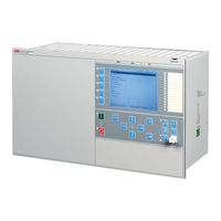
ABB RELION RET670 Applications Manual (744 pages)
Transformer protection
Brand: ABB
|
Category: Protection Device
|
Size: 10.28 MB
Table of Contents
-
Table of Contents
7
-
Introduction
27
-
This Manual
27
-
Intended Audience
27
-
Product Documentation
28
-
Product Documentation Set
28
-
Document Revision History
29
-
Related Documents
29
-
Document Symbols and Conventions
30
-
Symbols
30
-
Document Conventions
31
-
IEC61850 Edition 1 / Edition 2 Mapping
31
-
-
Application
39
-
General IED Application
39
-
Main Protection Functions
40
-
Back-Up Protection Functions
43
-
Control and Monitoring Functions
46
-
Communication
52
-
Basic IED Functions
55
-
-
Configuration
59
-
Introduction
59
-
Description of Configuration RET670
60
-
Introduction
60
-
Description of Configuration A30
60
-
Description of Configuration B30
61
-
Description of Configuration A40
63
-
Description of Configuration B40
65
-
Description of Configuration A10
67
-
Description of Configuration A25
69
-
-
Analog Inputs
71
-
Introduction
71
-
Setting Guidelines
71
-
Setting of the Phase Reference Channel
71
-
Example
72
-
Setting of Current Channels
72
-
Example 1
72
-
Example 2
73
-
Example 3
74
-
Examples on How to Connect, Configure and Set CT Inputs for most Commonly Used CT Connections
78
-
Example on How to Connect a Star Connected Three-Phase CT Set to the IED
79
-
Example How to Connect Delta Connected Three-Phase CT Set to the IED
82
-
Example How to Connect Single-Phase CT to the IED
84
-
Relationships between Setting Parameter Base Current, CT Rated Primary Current and Minimum Pickup of a Protection IED
85
-
Setting of Voltage Channels
86
-
Example
86
-
Examples How to Connect, Configure and Set VT Inputs for most Commonly Used VT Connections
86
-
Examples on How to Connect a Three Phase-To-Earth Connected VT to the IED
87
-
Example on How to Connect a Phase-To-Phase Connected VT to the IED
89
-
Example on How to Connect an Open Delta VT to the IED for High Impedance Earthed or Unearthed Netwoeks
91
-
Example How to Connect the Open Delta VT to the IED for Low Impedance Earthed or Solidly Earthed Power Systems
92
-
Example on How to Connect a Neutral Point VT to the IED
94
-
-
Local HMI
97
-
Display
98
-
Leds
99
-
Keypad
100
-
Local HMI Functionality
102
-
Protection and Alarm Indication
102
-
Parameter Management
103
-
Front Communication
103
-
-
Differential Protection
105
-
Transformer Differential Protection T2WPDIF and T3WPDIF
105
-
Identification
105
-
Application
105
-
Setting Guidelines
106
-
Restrained and Unrestrained Differential Protection
106
-
Elimination of Zero Sequence Currents
108
-
Inrush Restraint Methods
109
-
Overexcitation Restraint Method
109
-
Cross-Blocking between Phases
109
-
External/Internal Fault Discriminator
110
-
On-Line Compensation for On-Load Tap-Changer Position
111
-
Differential Current Alarm
111
-
Open CT Detection
112
-
Switch Onto Fault Feature
112
-
Setting Example
112
-
Introduction
112
-
Typical Main CT Connections for Transformer Differential Protection
113
-
Application Examples
114
-
Summary and Conclusions
121
-
High Impedance Differential Protection, Single Phase HZPDIF
122
-
Identification
122
-
Application
122
-
The Basics of the High Impedance Principle
123
-
Connection Examples for High Impedance Differential Protection
128
-
Connections for Three-Phase High Impedance Differential Protection
128
-
Connections for 1Ph High Impedance Differential Protection HZPDIF
129
-
Setting Guidelines
130
-
Configuration
130
-
Settings of Protection Function
130
-
T-Feeder Protection
130
-
Autotransformer Differential Protection
132
-
Tertiary Reactor Protection
137
-
Restricted Earth Fault Protection
139
-
Alarm Level Operation
140
-
Low Impedance Restricted Earth Fault Protection REFPDIF
141
-
Identification
141
-
Application
141
-
Transformer Winding, Solidly Earthed
142
-
Transformer Winding, Earthed through Zig-Zag Earthing Transformer
143
-
Autotransformer Winding, Solidly Earthed
143
-
Reactor Winding, Solidly Earthed
144
-
Multi-Breaker Applications
145
-
CT Earthing Direction
146
-
Setting Guidelines
146
-
Setting and Configuration
146
-
Settings
147
-
Additional Security Logic for Differential Protection LDRGFC
147
-
Identification
147
-
Application
148
-
Setting Guidelines
149
-
Advertisement
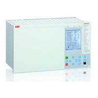
ABB RELION RET670 Applications Manual (1016 pages)
RELION 670 SERIES Transformer protection Version 2.2 ANSI
Brand: ABB
|
Category: Protection Device
|
Size: 14.18 MB
Table of Contents
-
Table of Contents
7
-
Table of Contents
14
-
Section 1 Introduction
33
-
This Manual
33
-
Intended Audience
33
-
Product Documentation
34
-
Product Documentation Set
34
-
Document Revision History
35
-
Related Documents
36
-
-
Document Symbols and Conventions
36
-
Symbols
36
-
Document Conventions
37
-
-
IEC 61850 Edition 1 / Edition 2 Mapping
38
-
-
Section 2 Application
49
-
General IED Application
49
-
Main Protection Functions
51
-
Back-Up Protection Functions
52
-
Control and Monitoring Functions
54
-
Communication
59
-
Basic IED Functions
62
-
-
Section 3 Configuration
65
-
Description of Configuration RET670
65
-
Description of Configuration A10
65
-
Introduction
65
-
Description of Configuration A25
68
-
Description of Configuration B30
69
-
Description of Configuration B40
72
-
-
-
Section 4 Analog Inputs
75
-
Introduction
75
-
Setting Guidelines
75
-
Setting of the Phase Reference Channel
75
-
Example
76
-
Setting of Current Channels
76
-
Example 1
77
-
Example 2
77
-
Example 3
78
-
For most Commonly Used CT Connections
81
-
Example on How to Connect a Wye Connected Three-Phase CT Set to the IED
82
-
Example How to Connect Delta Connected Three-Phase CT Set to the IED
87
-
Example How to Connect Single-Phase CT to the IED
90
-
Relationships between Setting Parameter Base Current, CT Rated Primary Current and Minimum Pickup of a Protection IED
92
-
Example
93
-
Examples on How to Connect a Three Phase-To-Ground Connected VT to the IED
94
-
Example on How to Connect a Phase-To-Phase Connected VT to the IED
96
-
Example on How to Connect an Open Delta VT to the IED for High Impedance Grounded or Ungrounded Networks
98
-
Example How to Connect the Open Delta VT to the IED for Low Impedance Grounded or Solidly Grounded Power Systems
101
-
-
-
Section 5 Local HMI
105
-
Display
106
-
Leds
109
-
Keypad
110
-
Local HMI Functionality
112
-
Parameter Management
113
-
Front Communication
114
-
C37.118 Phasor Measurement Data Streaming Protocol Configuration PMUCONF
115
-
Short Guidance for Use of TCP
116
-
Short Guidance for Use of UDP
117
-
Protocol Reporting Via IEEE 1344 and C37.118 PMUREPORT
119
-
Application
120
-
Operation Principle
122
-
Frequency Reporting
124
-
Reporting Filters
126
-
Scaling Factors for ANALOGREPORT Channels
127
-
PMU Report Function Blocks Connection Rules in PCM600 Application Configuration Tool (ACT)
129
-
Setting Guidelines
135
-
Transformer Differential Protection T2WPDIF and T3WPDIF (87T)
141
-
Setting Guidelines
142
-
Elimination of Zero Sequence Currents
146
-
Cross-Blocking between Phases
147
-
On-Line Compensation for On-Load Tap-Changer Position
149
-
Differential Current Alarm
150
-
Switch Onto Fault Feature
151
-
Typical Main CT Connections for Transformer Differential Protection
152
-
Application Examples
153
-
Summary and Conclusions
161
-
-
High Impedance Differential Protection, Single Phase HZPDIF (87)
163
-
Application
164
-
Connection Examples for High Impedance Differential Protection
170
-
Connections for 1Ph High Impedance Differential Protection HZPDIF (87)
171
-
Setting Guidelines
172
-
Configuration
173
-
-
Tertiary Reactor Protection
176
-
Restricted Earth Fault Protection (87N)
179
-
Alarm Level Operation
181
-
Low Impedance Restricted Earth Fault Protection REFPDIF (87N)
182
-
Transformer Winding, Solidly Grounded
183
-
Transformer Winding, Grounded through Zig-Zag Grounding Transformer
184
-
Autotransformer Winding, Solidly Grounded
185
-
Reactor Winding, Solidly Grounded
186
-
Multi-Breaker Applications
187
-
CT Grounding Direction
188
-
Settings
189
-
-
Additional Security Logic for Differential Protection LDRGFC (11)
190
-
Setting Guidelines
192
-
Compensated Lines ZMCPDIS (21), ZMCAPDIS (21), ZDSRDIR 21D)
195
-
System Grounding
196
-
Fault Infeed from Remote End
198
-
-
Load Encroachment
199
-
Long Transmission Line Application
200
-
Parallel Line Application with Mutual Coupling
201
-
Tapped Line Application
209
-
Series Compensation in Power Systems
211
-
Challenges in Protection of Series Compensated and Adjacent Power Lines
220
-
Impact of Series Compensation on Protective IED of Adjacent Lines
232
-
Distance Protection
233
-
Setting Guidelines
241
-
-
Setting of Zone1
242
-
Setting of Reverse Zone
243
-
Setting of Zones for Parallel Line Application
249
-
Setting of Reach in Resistive Direction
251
-
Load Impedance Limitation, with Load Encroachment Function Activated
253
-
Setting of Timers for Distance Protection Zones
254
-
Application
255
-
-
Resistive Reach with Load Encroachment Characteristic
261
-
Minimum Operate Currents
262
-
Distance Measuring Zones, Quadrilateral Characteristic ZMQPDIS 21), ZMQAPDIS (21), ZDRDIR (21D)
263
-
Fault Infeed from Remote End
267
-
Load Encroachment
268
-
Short Line Application
269
-
Long Transmission Line Application
270
-
Parallel Line Application with Mutual Coupling
271
-
Tapped Line Application
278
-
Setting Guidelines
281
-
Setting of Zone 1
282
-
Setting of Reverse Zone
283
-
Setting of Zones for Parallel Line Application
284
-
Setting of Reach in Resistive Direction
285
-
Load Impedance Limitation, Without Load Encroachment Function
286
-
Load Impedance Limitation, with Phase Selection with Load Encroachment, Quadrilateral Characteristic Function Activated
288
-
-
Setting of Timers for Distance Protection Zones
291
-
Setting Guidelines
292
-
Full-Scheme Distance Protection, Quadrilateral for Earth Faults ZMMPDIS (21), ZMMAPDIS (21)
296
-
Fault Infeed from Remote End
300
-
Load Encroachment
301
-
Short Line Application
302
-
Long Transmission Line Application
303
-
Tapped Line Application
309
-
Setting Guidelines
312
-
Setting of Reverse Zone
313
-
Setting of Zones for Parallel Line Application
314
-
Setting of Reach in Resistive Direction
315
-
Load Impedance Limitation, Without Load Encroachment Function
316
-
Load Impedance Limitation, with Load Encroachment Function Activated
318
-
Identification
319
-
Mho Impedance Supervision Logic ZSMGAPC
321
-
Setting Guidelines
322
-
Faulty Phase Identification with Load Encroachment FMPSPDIS (21)
323
-
Setting Guidelines
324
-
Load Encroachment
325
-
Distance Protection Zone, Quadrilateral Characteristic, Separate Settings ZMRPDIS (21), ZMRAPDIS (21) and ZDRDIR (21D)
326
-
Identification
327
-
Fault Infeed from Remote End
331
-
Load Encroachment
332
-
Short Line Application
333
-
Long Transmission Line Application
334
-
Tapped Line Application
341
-
Setting Guidelines
343
-
Setting of Zone 1
344
-
Setting of Reverse Zone
345
-
Setting of Zones for Parallel Line Application
346
-
Setting of Reach in Resistive Direction
347
-
Load Impedance Limitation, Without Load Encroachment Function
348
-
Load Impedance Limitation, with Phase Selection with Load Encroachment, Quadrilateral Characteristic Function Activated
350
-
Setting of Timers for Distance Protection Zones
351
-
Load Encroachment Characteristics
357
-
-
Phase-To-Ground Fault in Forward Direction
358
-
Phase-To-Ground Fault in Reverse Direction
360
-
Phase-To-Phase Fault in Forward Direction
361
-
Setting Guidelines
363
-
Resistive Reach with Load Encroachment Characteristic
364
-
Minimum Operate Currents
365
-
Setting Guidelines
366
-
-
Resistive Reach with Load Encroachment Characteristic
372
-
Minimum Operate Currents
373
-
Application
374
-
Fault Infeed from Remote End
377
-
Load Encroachment
378
-
Short Line Application
379
-
Long Transmission Line Application
380
-
Parallel Line Application with Mutual Coupling
381
-
Tapped Line Application
388
-
Setting Guidelines
390
-
Setting of Zone 1
391
-
Setting of Reverse Zone
392
-
Setting of Zones for Parallel Line Application
393
-
-
Setting the Reach with Respect to Load
394
-
Zone Reach Setting Lower than Minimum Load Impedance
395
-
Zone Reach Setting Higher than Minimum Load Impedance
397
-
-
Other Settings
398
-
ZMMMXU Settings
401
-
High Speed Distance Protection for Series Compensated Lines ZMFCPDIS (21)
402
-
System Grounding
403
-
Fault Infeed from Remote End
405
-
-
Load Encroachment
406
-
Short Line Application
407
-
Long Transmission Line Application
408
-
Parallel Line Application with Mutual Coupling
409
-
Tapped Line Application
416
-
Series Compensation in Power Systems
419
-
Increase in Power Transfer
420
-
Voltage and Current Inversion
421
-
Impact of Series Compensation on Protective IED of Adjacent Lines
430
-
Distance Protection
431
-
Underreaching and Overreaching Schemes
432
-
Setting Guidelines
439
-
Setting of Zone 1
440
-
-
Setting of Reverse Zone
441
-
Setting of Zones for Parallel Line Application
446
-
Setting of Reach in Resistive Direction
448
-
Load Impedance Limitation, Without Load Encroachment Function
449
-
Zone Reach Setting Higher than Minimum Load Impedance
450
-
Parameter Setting Guidelines
451
-
ZMMMXU Settings
454
-
Application
455
-
Setting Guidelines
456
-
Power Swing Logic PSLPSCH
464
-
Setting Guidelines
466
-
Blocking and Tripping Logic for Evolving Power Swings
471
-
-
Pole Slip Protection PSPPPAM (78)
472
-
Application
473
-
Setting Guidelines
475
-
Setting Example for Line Application
477
-
Setting Example for Generator Application
482
-
-
Out-Of-Step Protection OOSPPAM (78)
487
-
Setting Guidelines
490
-
-
Automatic Switch Onto Fault Logic ZCVPSOF
494
-
Setting Guidelines
495
-
-
Phase Preference Logic PPLPHIZ
496
-
Application
497
-
Setting Guidelines
500
-
-
Phase Preference Logic PPL2PHIZ
501
-
Application
502
-
Setting Guidelines
505
-
Under Impedance Protection for Generators and Transformers ZGVPDIS
507
-
Operating Zones
509
-
Zone 1 Operation
510
-
Zone 3 Operation
511
-
CT and VT Positions
512
-
External Block Signals
513
-
Setting Guidelines
514
-
Load Encroachment
515
-
Under Voltage Seal-In
516
-
Instantaneous Phase Overcurrent Protection PHPIOC (50)
519
-
Setting Guidelines
520
-
Meshed Network Without Parallel Line
521
-
Meshed Network with Parallel Line
523
-
Directional Phase Overcurrent Protection, Four Steps OC4PTOC(51_67)
525
-
Setting Guidelines
526
-
Settings for each Step
528
-
Setting Example
532
-
Instantaneous Residual Overcurrent Protection EFPIOC (50N)
537
-
Identification
540
-
Application
541
-
Setting Guidelines
543
-
Nd Harmonic Restrain
545
-
Switch Onto Fault Logic
546
-
Settings for each Step (X = 1, 2, 3 and 4)
547
-
Transformer Application Example
550
-
Four Step Directional Negative Phase Sequence Overcurrent Protection NS4PTOC (46I2)
555
-
Setting Guidelines
557
-
Common Settings for All Steps
560
-
Sensitive Directional Residual Overcurrent and Power Protection SDEPSDE (67N)
561
-
Identification
562
-
Setting Guidelines
564
-
Thermal Overload Protection, One Time Constant Fahrenheit Celsius LFPTTR/LCPTTR (26)
573
-
Setting Guideline
574
-
Breaker Failure Protection CCRBRF(50BF)
577
-
Setting Guidelines
578
-
Stub Protection STBPTOC (50STB)
581
-
Setting Guidelines
582
-
Pole Discrepancy Protection CCPDSC(52PD)
583
-
Setting Guidelines
584
-
Directional Underpower Protection GUPPDUP (37)
585
-
Setting Guidelines
587
-
Directional Overpower Protection GOPPDOP (32)
591
-
Setting Guidelines
593
-
Broken Conductor Check BRCPTOC (46)
597
-
Application
598
-
Application
599
-
SCB Protection
601
-
Setting Guidelines
603
-
Restrike Detection
605
-
Ns2Ptoc (46I2)
606
-
Features
607
-
Generator Continuous Unbalance Current Capability
608
-
Setting Guidelines
610
-
Pickup Sensitivity
611
-
Alarm Function
612
-
Base Quantities
613
-
Setting Guidelines
614
-
Voltage-Restrained Overcurrent Protection for Generator and Step-Up Transformer
616
-
Two Step Undervoltage Protection UV2PTUV (27)
619
-
Setting Guidelines
620
-
Backup Protection for Power System Faults
621
-
Two Step Overvoltage Protection OV2PTOV (59)
622
-
Identification
623
-
Setting Guidelines
624
-
Power Supply Quality
625
-
-
Two Step Residual Overvoltage Protection ROV2PTOV (59N)
627
-
Setting Guidelines
628
-
Power Supply Quality
629
-
Direct Grounded System
630
-
-
Overexcitation Protection OEXPVPH (24)
632
-
Setting Guidelines
635
-
Service Value Report
636
-
Setting Example
637
-
-
Voltage Differential Protection VDCPTOV (60)
638
-
Application
639
-
Setting Guidelines
640
-
-
Loss of Voltage Check LOVPTUV (27)
642
-
Underfrequency Protection SAPTUF (81)
643
-
Setting Guidelines
644
-
Identification
645
-
Rate-Of-Change of Frequency Protection SAPFRC (81)
646
-
Setting Guidelines
647
-
General Current and Voltage Protection CVGAPC
649
-
Current and Voltage Selection for CVGAPC Function
650
-
Base Quantities for CVGAPC Function
653
-
Inadvertent Generator Energization
654
-
Setting Guidelines
655
-
Negative Sequence Overcurrent Protection
657
-
Generator Stator Overload Protection in Accordance with IEC or ANSI Standards
660
-
Open Phase Protection for Transformer, Lines or Generators and Circuit Breaker Head Flashover Protection for Generators
662
-
Voltage Restrained Overcurrent Protection for Generator and Step-Up Transformer
663
-
Multipurpose Filter SMAIHPAC
667
-
Setting Guidelines
669
-
Current Circuit Supervision (87)
673
-
Setting Guidelines
674
-
Setting Guidelines
675
-
Setting of Common Parameters
676
-
Zero Sequence Based
677
-
Dead Line Detection
678
-
Fuse Failure Supervision VDSPVC (60)
679
-
Setting Guidelines
680
-
Synchronism Check, Energizing Check, and Synchronizing SESRSYN (25)
683
-
Synchronism Check
685
-
Energizing Check
687
-
Voltage Selection
688
-
External Fuse Failure
689
-
Application Examples
690
-
Single Circuit Breaker with Single Busbar
691
-
Single Circuit Breaker with Double Busbar, External Voltage Selection
692
-
Single Circuit Breaker with Double Busbar, Internal Voltage Selection
693
-
Double Circuit Breaker
694
-
Breaker-And-A-Half
695
-
Setting Guidelines
698
-
Apparatus Control APC
703
-
Bay Control QCBAY
709
-
Switch Controller SCSWI
710
-
Proxy for Signals from Switching Device Via GOOSE XLNPROXY
711
-
Reservation Function (QCRSV and RESIN)
714
-
Interaction between Modules
716
-
Setting Guidelines
720
-
Switch (SXCBR/SXSWI)
721
-
Proxy for Signals from Switching Device Via GOOSE XLNPROXY
722
-
Bay Reserve (QCRSV)
723
-
Configuration Guidelines
724
-
Interlocking for Line Bay ABC_LINE (3)
725
-
Signals from Bus-Coupler
726
-
Configuration Setting
730
-
Interlocking for Bus-Coupler Bay ABC_BC (3)
731
-
Signals from Bus-Coupler
734
-
Configuration Setting
735
-
Interlocking for Transformer Bay AB_TRAFO (3)
736
-
Signals from Bus-Coupler
737
-
Configuration Setting
738
-
Interlocking for Bus-Section Breaker A1A2_BS (3)
739
-
Configuration Setting
742
-
Interlocking for Bus-Section Disconnector A1A2_DC (3)
743
-
Signals in Double-Breaker Arrangement
746
-
Signals in Breaker and a Half Arrangement
749
-
Interlocking for Busbar Grounding Switch BB_ES (3)
750
-
Signals in Single Breaker Arrangement
751
-
Signals in Double-Breaker Arrangement
755
-
Signals in Breaker and a Half Arrangement
756
-
Interlocking for Double CB Bay DB (3)
757
-
Interlocking for Breaker-And-A-Half Diameter BH (3)
758
-
Configuration Setting
759
-
Voltage Control
760
-
Setting Guidelines
796
-
TR1ATCC (90) or TR8ATCC (90) Setting Group
797
-
TCMYLTC and TCLYLTC (84) General Settings
807
-
Logic Rotating Switch for Function Selection and LHMI Presentation SLGAPC
808
-
Selector Mini Switch VSGAPC
809
-
Setting Guidelines
810
-
Setting Guidelines
811
-
Identification
812
-
Identification
813
-
Application
814
-
Setting Guidelines
815
-
Scheme Communication Logic for Distance or Overcurrent Protection ZCPSCH(85)
817
-
-
Blocking Schemes
818
-
Delta Blocking Scheme
819
-
Permissive Schemes
820
-
Intertrip Scheme
824
-
Delta Blocking Scheme
825
-
Intertrip Scheme
826
-
Blocking Scheme
828
-
Intertrip Scheme
830
-
Permissive Underreache Scheme
831
-
Current Reversal and Weak-End Infeed Logic for Distance Protection 3-Phase ZCRWPSCH (85)
832
-
Weak-End Infeed Logic
833
-
Setting Guidelines
834
-
Current Reversal and Weak-End Infeed Logic for Phase Segregated Communication ZC1WPSCH (85)
835
-
Setting Guidelines
837
-
Scheme Communication Logic for Residual Overcurrent Protection ECPSCH (85)
838
-
Setting Guidelines
839
-
Current Reversal and Weak-End Infeed Logic for Residual Overcurrent Protection ECRWPSCH (85)
840
-
-
Weak-End Infeed Logic
841
-
Current Reversal
842
-
Weak-End Infeed
843
-
-
Tripping Logic SMPPTRC (94)
845
-
Three-Pole Tripping
846
-
Single- And/Or Three-Pole Tripping
847
-
Single-, Two- or Three-Pole Tripping
848
-
Lock-Out
849
-
Blocking of the Function Block
851
-
Identification
852
-
Application
853
-
Application
854
-
Configuration
855
-
Fixed Signal Function Block FXDSIGN
856
-
Boolean 16 to Integer Conversion B16I
857
-
Application
858
-
Boolean to Integer Conversion with Logical Node Representation
859
-
Integer to Boolean 16 Conversion IB16
860
-
Integer to Boolean 16 Conversion with Logic Node Representation ITBGAPC
861
-
Identification
862
-
Elapsed Time Integrator with Limit Transgression and Overflow Supervision TEIGAPC
863
-
Comparator for Integer Inputs — INTCOMP
864
-
Setting Example
865
-
Comparator for Real Inputs — REALCOMP
866
-
Setting Example
867
-
Measurement
869
-
Application
870
-
Zero Clamping
871
-
Setting Guidelines
872
-
Setting Examples
875
-
Gas Medium Supervision SSIMG (63)
882
-
Setting Guidelines
883
-
Liquid Medium Supervision SSIML (71)
884
-
Breaker Monitoring SSCBR
885
-
Setting Guidelines
889
-
Event Function EVENT
890
-
Setting Guidelines
891
-
Identification
892
-
Setting Guidelines
893
-
Recording Times
896
-
Analog Input Signals
897
-
Sub-Function Parameters
898
-
Logical Signal Status Report BINSTATREP
899
-
Application
900
-
Setting Guidelines
901
-
Connection of Analog Currents
902
-
Limit Counter L4UFCNT
903
-
Application
904
-
Setting Guidelines
905
-
Setting Guidelines
910
-
Setting Example
919
-
Setting Parameters for Insulation Loss of Life Calculation Function (LOL1)
920
-
Pulse-Counter Logic PCFCNT
925
-
Function for Energy Calculation and Demand Handling ETPMMTR
926
-
Setting Guidelines
927
-
Access Point
929
-
Redundant Communication
931
-
Setting Guidelines
933
-
Merging Unit
934
-
Setting Guidelines
935
-
Communication Protocols
937
-
Setting Guidelines
939
-
Receiving Data
940
-
LON Communication Protocol
942
-
MULTICMDRCV and MULTICMDSND
944
-
Setting Guidelines
946
-
IEC 60870-5-103 Communication Protocol
947
-
Design
948
-
Settings
951
-
Settings from PCM600
952
-
Function and Information Types
954
-
DNP3 Communication Protocol
955
-
Binary Signal Transfer
957
-
Communication Hardware Solutions
958
-
Setting Guidelines
959
-
Authority Status ATHSTAT
965
-
Change Lock CHNGLCK
966
-
Denial of Service SCHLCCH/RCHLCCH
967
-
Setting Guidelines
968
-
IED Identifiers TERMINALID
969
-
Factory Defined Settings
970
-
Identification
971
-
Setting Guidelines
972
-
Summation Block 3 Phase 3PHSUM
973
-
Application
974
-
Signal Matrix for Binary Outputs SMBO
975
-
Application
976
-
Setting Guidelines
977
-
Test Mode Functionality TESTMODE
982
-
Setting Guidelines
983
-
Time Synchronization TIMESYNCHGEN
984
-
Setting Guidelines
985
-
Current Transformer Requirements
989
-
Conditions
991
-
Fault Current
992
-
General Current Transformer Requirements
993
-
Transformer Differential Protection
994
-
Distance Protection
995
-
Breaker Failure Protection
996
-
Restricted Ground Fault Protection (Low Impedance Differential)
997
-
Current Transformer Requirements for Cts According to Other Standards
999
-
Current Transformers According to IEC 61869-2, Class P, PR
1000
-
Voltage Transformer Requirements
1001
-
SNTP Server Requirements
1002
-
-
-
Section 26 Glossary
1005
-

ABB RELION RET670 Applications Manual (888 pages)
Brand: ABB
|
Category: Protection Device
|
Size: 18.28 MB
Table of Contents
-
Table of Contents
7
-
Section 1 Introduction
21
-
Introduction to the Application Manual
21
-
About the Complete Set of Manuals for an IED
21
-
About the Application Manual
22
-
Intended Audience
23
-
Related Documents
23
-
Revision Notes
23
-
-
-
Section 2 Requirements
25
-
Current Transformer Requirements
25
-
Current Transformer Classification
25
-
Conditions
26
-
Fault Current
27
-
Secondary Wire Resistance and Additional Load
27
-
General Current Transformer Requirements
28
-
Rated Equivalent Secondary E.M.f. Requirements
28
-
Transformer Differential Protection
28
-
Distance Protection
29
-
Restricted Ground Fault Protection (Low Impedance Differential)
30
-
-
Current Transformer Requirements for Cts According to Other Standards
33
-
Current Transformers According to IEC 60044-1, Class P, PR
33
-
Current Transformers According to ANSI/IEEE
34
-
Current Transformers According to IEC 60044-1, Class PX, IEC 60044-6, Class TPS (and Old British Standard, Class X)
34
-
-
-
Voltage Transformer Requirements
35
-
SNTP Server Requirements
35
-
IEC 61850-9-2LE Merging Unit Requirements
36
-
-
Section 3 IED Application
37
-
General IED Application
37
-
Analog Inputs
39
-
Introduction
39
-
Setting Guidelines
39
-
Setting of the Phase Reference Channel
39
-
-
Setting Parameters
68
-
-
Local Human-Machine Interface
75
-
Human Machine Interface
75
-
Local HMI Related Functions
76
-
General Setting Parameters
76
-
Introduction
76
-
-
Indication Leds
77
-
Introduction
77
-
Setting Parameters
78
-
-
-
Basic IED Functions
80
-
Self Supervision with Internal Event List
80
-
Application
80
-
Setting Parameters
80
-
-
Time Synchronization
81
-
Application
81
-
Setting Guidelines
81
-
Setting Parameters
83
-
-
Parameter Setting Groups
87
-
Application
87
-
Setting Guidelines
87
-
Setting Parameters
87
-
-
Test Mode Functionality TEST
88
-
Application
88
-
Setting Guidelines
88
-
Setting Parameters
88
-
-
Change Lock CHNGLCK
88
-
Application
89
-
Setting Parameters
90
-
-
IED Identifiers
90
-
Application
90
-
-
Product Information
90
-
Setting Parameters
91
-
-
Rated System Frequency PRIMVAL
91
-
Application
92
-
Setting Guidelines
92
-
Setting Parameters
92
-
-
Signal Matrix for Binary Inputs SMBI
92
-
Signal Matrix for Binary Outputs SMBO
92
-
Application
93
-
Setting Guidelines
93
-
Setting Parameters
93
-
-
Signal Matrix for Ma Inputs SMMI
93
-
Signal Matrix for Analog Inputs SMAI
94
-
Application
94
-
Frequency Values
94
-
Setting Guidelines
95
-
Setting Parameters
100
-
-
Summation Block 3 Phase 3PHSUM
101
-
Application
101
-
Setting Guidelines
101
-
Setting Parameters
102
-
-
Authority Status ATHSTAT
102
-
Application
102
-
Setting Parameters
103
-
-
Denial of Service DOS
103
-
Application
103
-
Setting Guidelines
103
-
-
-
Differential Protection
103
-
Transformer Differential Protection T2WPDIF (87T) and T3WPDIF (87T)
103
-
Application
104
-
Setting Guidelines
105
-
Setting Example
114
-
Setting Parameters
126
-
-
Restricted Earth-Fault Protection, Low Impedance REFPDIF (87N)
131
-
Application
132
-
Setting Guidelines
137
-
Setting Parameters
139
-
-
1Ph High Impedance Differential Protection HZPDIF (87)
140
-
Application
140
-
Identification
140
-
Connection Examples for High Impedance Differential Protection
147
-
Setting Guidelines
150
-
Setting Parameters
165
-
-
-
Impedance Protection
165
-
Distance Measuring Zones, Quadrilateral Characteristic ZMQPDIS (21), ZMQAPDIS (21), ZDRDIR (21D)
165
-
Application
165
-
Identification
165
-
Setting Guidelines
183
-
Setting Parameters
193
-
-
Distance Measuring Zone, Quadrilateral Characteristic for Series Compensated Lines ZMCPDIS (21), ZMCAPDIS (21), ZDSRDIR (21D)
195
-
Application
195
-
Setting Guidelines
241
-
Setting Parameters
254
-
-
Phase Selection, Quadrilateral Characteristic with Fixed Angle
257
-
Fdpspdis (21)
257
-
Identification
257
-
Application
258
-
Setting Guidelines
258
-
Setting Parameters
265
-
-
Full-Scheme Distance Measuring, Mho Characteristic ZMHPDIS (21)
266
-
Application
266
-
Setting Guidelines
280
-
Setting Parameters
287
-
-
Full-Scheme Distance Protection, Quadrilateral for Earth Faults ZMMPDIS (21), ZMMAPDIS (21)
289
-
Zmmpdis (21), Zmmapdis (21)
289
-
Application
289
-
Setting Guidelines
304
-
Setting Parameters
311
-
-
Additional Distance Protection Directional Function for Earth Faults ZDARDIR
312
-
Application
312
-
Setting Guidelines
312
-
Setting Parameters
315
-
-
Mho Impedance Supervision Logic ZSMGAPC
315
-
Application
315
-
Setting Guidelines
316
-
Setting Parameters
317
-
-
Faulty Phase Identification with Load Encroachment FMPSPDIS
317
-
Application
318
-
Setting Guidelines
318
-
Setting Parameters
321
-
-
Distance Protection Zone, Quadrilateral Characteristic, Separate Settings ZMRPDIS (21), ZMRAPDIS (21) and ZDRDIR (21D)
322
-
Application
322
-
Setting Guidelines
338
-
Setting Parameters
345
-
-
Phase Selection, Quadrilateral Characteristic with Settable Angle FRPSPDIS (21)
347
-
Application
347
-
Load Encroachment Characteristics
353
-
Setting Guidelines
359
-
Setting Parameters
361
-
-
Power Swing Detection ZMRPSB (68)
362
-
Application
362
-
Setting Guidelines
364
-
Setting Parameters
371
-
-
Power Swing Logic ZMRPSL
372
-
Application
372
-
Setting Guidelines
374
-
Setting Parameters
380
-
-
Pole Slip Protection PSPPPAM (78)
380
-
Application
380
-
Setting Guidelines
383
-
Setting Parameters
395
-
-
Phase Preference Logic PPLPHIZ
395
-
Application
396
-
Setting Guidelines
399
-
Setting Parameters
401
-
-
-
Current Protection
401
-
Instantaneous Phase Overcurrent Protection 3-Phase Output PHPIOC (50)
401
-
Application
402
-
Setting Guidelines
402
-
Setting Parameters
407
-
-
Four Step Phase Overcurrent Protection OC4PTOC (51/67)
407
-
Setting Guidelines
409
-
Setting Parameters
419
-
-
-
Instantaneous Residual Overcurrent Protection EFPIOC (50N)
424
-
Application
425
-
Setting Parameters
428
-
Setting Guidelines
430
-
Setting Parameters
441
-
Four Step Directional Negative Phase Sequence Overcurrent Protection NS4PTOC (46I2)
446
-
Setting Guidelines
448
-
Setting Parameters
452
-
Sensitive Directional Residual Overcurrent and Power Protection SDEPSDE (67N)
457
-
Setting Guidelines
459
-
Setting Parameters
469
-
-
Thermal Overload Protection, Two Time Constants TRPTTR (49)
471
-
Setting Guideline
472
-
Setting Parameters
475
-
-
Breaker Failure Protection CCRBRF (50BF)
476
-
Setting Parameters
480
-
Application
481
-
Setting Parameters
482
-
-
Directional Underpower Protection GUPPDUP (37)
483
-
Setting Guidelines
485
-
Setting Parameters
489
-
-
Directional Overpower Protection GOPPDOP (32)
490
-
Application
491
-
Setting Guidelines
493
-
Setting Parameters
497
-
Broken Conductor Check BRCPTOC (46)
499
-
Setting Parameters
500
-
Setting Guidelines
504
-
Setting Parameters
507
-
Negativ Sequence Time Overcurrent Protection for Machines NS2PTOC (46I2)
508
-
Setting Guidelines
511
-
Setting Parameters
514
-
-
-
Voltage Protection
515
-
Setting Guidelines
516
-
Setting Parameters
519
-
Two Step Overvoltage Protection OV2PTOV (59)
521
-
Setting Guidelines
522
-
Setting Parameters
525
-
Two Step Residual Overvoltage Protection ROV2PTOV (59N)
527
-
Setting Guidelines
528
-
-
Setting Parameters
533
-
Overexcitation Protection OEXPVPH (24)
535
-
Setting Guidelines
537
-
Setting Parameters
541
-
-
Voltage Differential Protection VDCPTOV (60)
542
-
Application
543
-
Setting Guidelines
544
-
Setting Parameters
546
-
-
Application
547
-
-
Frequency Protection
548
-
Setting Guidelines
549
-
Setting Parameters
550
-
Overfrequency Protection SAPTOF (81)
551
-
Setting Parameters
552
-
Rate-Of-Change Frequency Protection SAPFRC (81)
553
-
Setting Parameters
554
-
-
Multipurpose Protection
555
-
Setting Guidelines
561
-
Setting Parameters
571
-
-
Secondary System Supervision
578
-
Setting Guidelines
579
-
Fuse Failure Supervision SDDRFUF
580
-
Setting Guidelines
581
-
-
Setting Parameters
584
-
-
Control
585
-
Application
586
-
Application Examples
591
-
Setting Guidelines
600
-
Setting Parameters
605
-
Apparatus Control APC
608
-
Application
609
-
Interaction between Modules
615
-
Setting Guidelines
617
-
-
Setting Parameters
619
-
Interlocking (3)
621
-
Configuration Guidelines
623
-
Interlocking for Bus-Coupler Bay ABC_BC (3)
629
-
Interlocking for Transformer Bay AB_TRAFO (3)
634
-
Interlocking for Bus-Section Breaker A1A2_BS (3)
636
-
Interlocking for Bus-Section Disconnector A1A2_DC (3)
639
-
Interlocking for Busbar Grounding Switch BB_ES (3)
647
-
Interlocking for Double CB Bay DB (3)
654
-
Interlocking for Breaker-And-A-Half Diameter BH (3)
656
-
Horizontal Communication Via GOOSE for Interlocking GOOSEINTLKRCV
657
-
-
Application
658
-
Setting Guidelines
693
-
-
Setting Parameters
704
-
Logic Rotating Switch for Function Selection and LHMI Presentation SLGGIO
712
-
Setting Parameters
713
-
Setting Guidelines
714
-
-
IEC61850 Generic Communication I/O Functions DPGGIO
715
-
Setting Guidelines
716
-
Automationbits, Command Function for DNP3.0 AUTOBITS
717
-
Single Command, 16 Signals SINGLECMD
732
-
Setting Guidelines
735
-
Setting Guidelines
736
-
Setting Parameters
737
-
-
Application
738
-
Setting Guidelines
739
-
Setting Parameters
741
-
Setting Guidelines
746
-
Setting Parameters
747
-
Setting Parameters
748
-
Setting Parameters
749
-
-
-
Fixed Signal Function Block FXDSIGN
750
-
Setting Parameters
752
-
Setting Guidelines
753
-
Setting Parameters
754
-
Zero Clamping
756
-
Setting Guidelines
757
-
Setting Parameters
767
-
-
Event Counter CNTGGIO
781
-
-
Introduction
782
-
Setting Parameters
783
-
Logical Signal Status Report BINSTATREP
785
-
Setting Guidelines
786
-
Application
787
-
Setting Guidelines
788
-
Setting Parameters
794
-
-
Sequential of Events
804
-
Setting Guidelines
805
-
Setting Guidelines
806
-
Setting Guidelines
807
-
Setting Guidelines
808
-
Setting Guidelines
809
-
Function for Energy Calculation and Demand Handling ETPMMTR
810
-
Setting Guidelines
811
-
Setting Parameters
812
-
-
-
Overview
815
-
Setting Guidelines
817
-
IEC 61850 Generic Communication I/O Functions SPGGIO SP16GGIO
818
-
Setting Parameters
819
-
Setting Guidelines
821
-
Setting Parameters
822
-
-
IEC 61850-9-2LE Communication Protocol
823
-
Setting Guidelines
826
-
Functions When Using Signals from IEC 61850-9-2LE Communication
827
-
Setting Examples for IEC 61850-9-2LE and Time Synchronization
830
-
Setting Parameters
834
-
-
LON Communication Protocol
835
-
Setting Parameters
836
-
SPA Communication Protocol
837
-
Setting Guidelines
839
-
Setting Parameters
840
-
-
IEC 60870-5-103 Communication Protocol
841
-
Setting Parameters
846
-
Multiple Command and Transmit MULTICMDRCV MULTICMDSND
849
-
Application
850
-
-
Advertisement

ABB RELION RET670 Commissioning Manual (330 pages)
Transformer protection
Brand: ABB
|
Category: Transformer
|
Size: 7.14 MB
Table of Contents
-
Table of Contents
7
-
Introduction
21
-
Intended Audience
21
-
This Manual
21
-
Product Documentation
22
-
Product Documentation Set
22
-
Document Revision History
23
-
Document Symbols and Conventions
24
-
Related Documents
24
-
Symbols
24
-
Document Conventions
25
-
IEC 61850 Edition 1 / Edition 2 Mapping
26
-
-
Safety Information
31
-
Symbols on the Product
31
-
Warnings
31
-
Caution Signs
32
-
Note Signs
33
-
-
Available Functions
35
-
Main Protection Functions
35
-
Back-Up Protection Functions
36
-
Control and Monitoring Functions
38
-
Communication
44
-
Basic IED Functions
47
-
-
Starting up
51
-
Commissioning Checklist
51
-
Factory and Site Acceptance Testing
51
-
Checking the IED Operation
52
-
Checking the Power Supply
52
-
Energizing the IED
52
-
IED Start-Up Sequence
52
-
Setting up Communication between PCM600 and the IED
53
-
Checking CT Circuits
58
-
Writing an Application Configuration to the IED
58
-
Checking VT Circuits
59
-
Using the RTXP Test Switch
59
-
Binary Input Circuits
60
-
Binary Output Circuits
60
-
Checking Optical Connections
60
-
Configuring the IED and Changing Settings
61
-
-
Checking the Binary Input/Output Circuits
60
-
-
Section 5 Configuring the IED and Changing Settings
61
-
Overview
61
-
Configuring Analog CT Inputs
61
-
Supervision of Input/Output Modules
62
-
Establishing Connection and Verifying the SPA/IEC Communication
63
-
-
-
Section 6 Establishing Connection and Verifying the SPA/IEC Communication
63
-
Entering Settings
63
-
Entering SPA Settings
63
-
Entering IEC Settings
63
-
Verifying the Communication
64
-
Verifying SPA Communication
64
-
Verifying IEC Communication
64
-
Fiber Optic Loop
64
-
Optical Budget Calculation for Serial Communication with SPA/IEC
65
-
Establishing Connection and Verifying the LON Communication
67
-
-
-
Section 7 Establishing Connection and Verifying the LON Communication
67
-
Communication Via the Rear Ports
67
-
LON Communication
67
-
The LON Protocol
68
-
Hardware and Software Modules
68
-
Optical Budget Calculation for Serial Communication with LON
70
-
Establishing Connection and Verifying the IEC 61850 Communication
71
-
-
-
Section 8 Establishing Connection and Verifying the IEC 61850 Communication
71
-
Overview
71
-
Setting the Station Communication
71
-
Verifying the Communication
71
-
Establishing Connection and Verifying the IEEE C37.118/1344 Communication
73
-
-
-
Section 9 Establishing Connection and Verifying the IEEE C37.118/1344
73
-
Overview
73
-
Setting the PMU Station Communication (PMU Report)
73
-
Setting the PMU Station Communication (PMU Configuration)
73
-
Setting the TCP/UDP Client Communication
74
-
Verifying the Communication
78
-
Verifying the IEEE C37.118/1344 TCP Communication
78
-
Verifying the IEEE C37.118/1344 UDP Communication
84
-
Optical Budget Calculation for PMU — PDC Communication
85
-
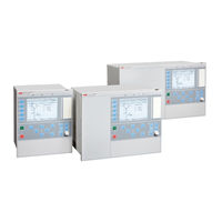
ABB RELION RET670 Commissioning Manual (328 pages)
Transformer protection
Brand: ABB
|
Category: Protection Device
|
Size: 5.83 MB
Table of Contents
-
Table of Contents
7
-
Section 1 Introduction
19
-
This Manual
19
-
Intended Audience
19
-
Product Documentation
20
-
Product Documentation Set
20
-
Document Revision History
21
-
Related Documents
22
-
-
Document Symbols and Conventions
22
-
Symbols
22
-
Document Conventions
23
-
-
IEC 61850 Edition 1 / Edition 2 Mapping
24
-
-
Section 2 Safety Information
35
-
Symbols on the Product
35
-
Warnings
35
-
Caution Signs
37
-
Note Signs
38
-
-
Section 3 Available Functions
39
-
Main Protection Functions
39
-
Back-Up Protection Functions
40
-
Control and Monitoring Functions
42
-
Communication
47
-
Basic IED Functions
49
-
-
Section 4 Starting up
51
-
Factory and Site Acceptance Testing
51
-
Commissioning Checklist
51
-
Checking the Power Supply
52
-
Energizing the IED
52
-
Checking the IED Operation
52
-
IED Start-Up Sequence
53
-
-
Setting up Communication between PCM600 and the IED
53
-
Writing an Application Configuration to the IED
58
-
Checking CT Circuits
59
-
Checking VT Circuits
60
-
Using the RTXP Test Switch
60
-
Checking the Binary Input/Output Circuits
61
-
Binary Input Circuits
61
-
Binary Output Circuits
62
-
-
Checking Optical Connections
62
-
-
Section 5 Configuring the IED and Changing Settings
63
-
Overview
63
-
Configuring Analog CT Inputs
64
-
Supervision of Input/Output Modules
64
-
-
Section 6 Establishing Connection and Verifying the SPA/IEC Communication
67
-
Entering Settings
67
-
Entering SPA Settings
67
-
Entering IEC Settings
67
-
-
Verifying the Communication
68
-
Verifying SPA Communication
68
-
Verifying IEC Communication
68
-
-
Fibre Optic Loop
69
-
Optical Budget Calculation for Serial Communication with SPA/IEC
69
-
-
Section 7 Establishing Connection and Verifying the LON Communication
71
-
Communication Via the Rear Ports
71
-
LON Communication
71
-
The LON Protocol
72
-
Hardware and Software Modules
72
-
-
Optical Budget Calculation for Serial Communication with LON
74
-
-
Section 8 Establishing Connection and Verifying the IEC 61850 Communication
77
-
Overview
77
-
Setting the Station Communication
77
-
Verifying the Communication
78
-
-
Section 9 Establishing Connection and Verifying the IEEE C37.118/1344 Communication
79
-
Overview
79
-
Setting the PMU Station Communication (PMU Report)
79
-
Setting the PMU Station Communication (PMU Configuration)
80
-
Setting the TCP/UDP Client Communication
81
-
Verifying the Communication
84
-
Verifying the IEEE C37.118/1344 TCP Communication
85
-
Verifying the IEEE C37.118/1344 UDP Communication
91
-
-
Optical Budget Calculation for PMU — PDC Communication
92
-

ABB RELION RET670 Commissioning Manual (318 pages)
RELION 670 Series, Transformer protection
Brand: ABB
|
Category: Protection Device
|
Size: 6.07 MB
Table of Contents
-
Table of Contents
7
-
Section 1 Introduction
19
-
This Manual
19
-
Intended Audience
19
-
Product Documentation
20
-
Product Documentation Set
20
-
Document Revision History
21
-
Related Documents
22
-
-
Document Symbols and Conventions
22
-
Symbols
22
-
Document Conventions
23
-
-
IEC 61850 Edition 1 / Edition 2 Mapping
24
-
-
Section 2 Safety Information
33
-
Symbols on the Product
33
-
Warnings
33
-
Caution Signs
35
-
Note Signs
35
-
-
Section 3 Available Functions
37
-
Main Protection Functions
37
-
Back-Up Protection Functions
39
-
Control and Monitoring Functions
41
-
Communication
48
-
Basic IED Functions
51
-
-
Section 4 Starting up
53
-
Factory and Site Acceptance Testing
53
-
Commissioning Checklist
53
-
Checking the Power Supply
54
-
Energizing the IED
54
-
Checking the IED Operation
54
-
IED Start-Up Sequence
55
-
-
Setting up Communication between PCM600 and the IED
55
-
Writing an Application Configuration to the IED
60
-
Checking CT Circuits
61
-
Checking VT Circuits
62
-
Using the RTXP Test Switch
62
-
Checking the Binary Input/Output Circuits
63
-
Binary Input Circuits
63
-
Binary Output Circuits
63
-
-
Checking Optical Connections
64
-
-
Section 5 Configuring the IED and Changing Settings
65
-
Overview
65
-
Configuring Analog CT Inputs
66
-
Supervision of Input/Output Modules
66
-
-
Section 6 Establishing Connection and Verifying the SPA/IEC Communication
69
-
Entering Settings
69
-
Entering SPA Settings
69
-
Entering IEC Settings
69
-
-
Verifying the Communication
70
-
Verifying SPA Communication
70
-
Verifying IEC Communication
70
-
-
Fibre Optic Loop
71
-
Optical Budget Calculation for Serial Communication with SPA/IEC
71
-
-
Section 7 Establishing Connection and Verifying the LON Communication
73
-
Communication Via the Rear Ports
73
-
LON Communication
73
-
The LON Protocol
74
-
Hardware and Software Modules
74
-
-
Optical Budget Calculation for Serial Communication with LON
76
-
-
Section 8 Establishing Connection and Verifying the IEC 61850 Communication
77
-
Overview
77
-
Setting the Station Communication
77
-
Verifying the Communication
78
-
-
Section 9 Establishing Connection and Verifying the IEEE C37.118/1344 Communication
79
-
Overview
79
-
Setting the PMU Station Communication (PMU Report)
79
-
Setting the PMU Station Communication (PMU Configuration)
80
-
Setting the TCP/UDP Client Communication
81
-
Verifying the Communication
84
-
Verifying the IEEE C37.118/1344 TCP Communication
85
-
Verifying the IEEE C37.118/1344 UDP Communication
91
-
-
Optical Budget Calculation for PMU — PDC Communication
92
-
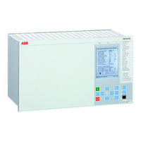
ABB RELION RET670 Installation And Commissioning Manual (240 pages)
Brand: ABB
|
Category: Protection Device
|
Size: 5.3 MB
Table of Contents
-
Table of Contents
7
-
Section 1 Introduction
17
-
Introduction to the Installation and Commissioning Manual
17
-
About the Complete Set of Manuals for an IED
17
-
About the Installation and Commissioning Manual
18
-
Intended Audience
19
-
Related Documents
19
-
Revision Notes
20
-
-
-
Section 2 Safety Information
21
-
Warning Signs
21
-
Caution Signs
22
-
Note Signs
23
-
-
Section 3 Overview
25
-
Commissioning and Installation Overview
25
-
-
Section 4 Unpacking and Checking the IED
27
-
Taking Delivery, Unpacking and Checking
27
-
-
Section 5 Installing the IED
29
-
Overview
29
-
Dimensions
30
-
Case Without Rear Cover
30
-
Case with Rear Cover
32
-
Flush Mounting Dimensions
34
-
Side-By-Side Flush Mounting Dimensions
35
-
Wall Mounting Dimensions
36
-
-
Mounting Methods and Details
36
-
Mounting the IED
36
-
Flush Mounting
38
-
Overview
38
-
Mounting Procedure for Flush Mounting
39
-
19″ Panel Rack Mounting
40
-
Overview
40
-
Mounting Procedure for 19″ Panel Rack Mounting
41
-
-
Wall Mounting
42
-
Mounting Procedure for Wall Mounting
42
-
Overview
42
-
How to Reach the Rear Side of the IED
43
-
Overview
44
-
Side-By-Side 19″ Rack Mounting
44
-
IED in the 670 Series Mounted with a RHGS6 Case
45
-
Mounting Procedure for Side-By-Side Rack Mounting
45
-
Overview
46
-
Side-By-Side Flush Mounting
46
-
Mounting Procedure for Side-By-Side Flush Mounting
47
-
-
Making the Electrical Connection
48
-
IED Connectors
48
-
Overview
48
-
Front Side Connectors
50
-
Rear Side Connectors
51
-
Connection Examples
61
-
Connecting to Protective Earth
64
-
Connecting the Power Supply Module
65
-
Connecting to CT and VT Circuits
65
-
Configuration for Analog CT Inputs
66
-
Connecting the Binary Input and Output Signals
66
-
Making the Screen Connection
68
-
-
Making the Optical Connections
69
-
Connecting Station Communication Interfaces
69
-
Connecting Remote Communication Interfaces LDCM
70
-
-
Installing the Serial Communication Cable for RS485
71
-
RS485 Serial Communication Module
71
-
Installing the Serial Communication Cable for RS485 SPA/IEC
74
-
Data on RS485 Serial Communication Module Cable
76
-
-
Installing the GPS Antenna
76
-
Antenna Installation
76
-
Electrical Installation
78
-
Lightning Protection
78
-
-
-
ABB RELION RET670 Operator’s Manual (128 pages)
Transformer protection
Brand: ABB
|
Category: Protection Device
|
Size: 3.27 MB
Table of Contents
-
Table of Contents
7
-
Section 1 Introduction
17
-
Introduction to the Operator’s Manual
17
-
About the Complete Set of Manuals for an IED
17
-
About the Operator’s Manual
18
-
Intended Audience
19
-
Related Documents
19
-
Revision Notes
20
-
-
-
Section 2 Safety Information
21
-
Warnings
21
-
-
Section 3 Overview
23
-
Operator Overview
23
-
Identify the IED
23
-
-
Section 4 Understand the IED Local Human-Machine Interface
27
-
Overview
27
-
Keypad
28
-
Key Activated Screens
29
-
The Help Screen
29
-
The Reset Screen
30
-
-
Lcd
30
-
Small
30
-
Medium
30
-
-
Led
31
-
Introduction
31
-
Status Indication Leds
31
-
Indication Leds
31
-
-
Local HMI Setup
32
-
How to Navigate
32
-
Read
32
-
Change
32
-
Control
33
-
-
-
Section 5 Understand the HMI Tree
35
-
Overview
35
-
Menu-Tree for RET670
35
-
-
-
Section 6 Read Measured Values
37
-
Overview
37
-
View Analog Primary Values
38
-
Overview
38
-
-
View Analog Secondary Values
38
-
View Analog Mean Values
39
-
Ma Input Module MIM
39
-
Overview
39
-
Signal Matrix for Ma Inputs SMMI
39
-
-
View Monitoring Values
39
-
Current Phasors CMMXU
39
-
Service Values CVMMXN
39
-
Current Sequence Component CMSQI
40
-
Voltage Phasors VMMXU/VNMMXU
40
-
Voltage Sequence Component VMSQI
40
-
-
View Metering Values
40
-
Pulse Counter Logic PCGGIO
40
-
Function for Energy Calculation and Demand Handling ETPMMTR
41
-
-
-
-
Section 7 Event List
43
-
View Events
43
-
Overview
43
-
-
-
Section 8 Handle Disturbances
45
-
Identify a Disturbance
45
-
View Disturbance Record Details
45
-
View General Information
45
-
View Disturbance Indications
45
-
View Event Recordings
45
-
View Trip Values
46
-
Trigger a Disturbance Report Manually
46
-
-

ABB RELION RET670 Commissioning Manual (254 pages)
Transformer protection Version 2.1 ANSI
Brand: ABB
|
Category: Power distribution unit
|
Size: 4.31 MB
Table of Contents
-
Table of Contents
7
-
Introduction
17
-
This Manual
17
-
Intended Audience
17
-
Section 1 Introduction
17
-
Product Documentation
18
-
Product Documentation Set
18
-
Document Revision History
19
-
Related Documents
19
-
Document Symbols and Conventions
20
-
Symbols
20
-
Document Conventions
21
-
IEC61850 Edition 1 / Edition 2 Mapping
21
-
-
Safety Information
29
-
Symbols on the Product
29
-
Warnings
29
-
Section 2 Safety Information
29
-
Caution Signs
30
-
Note Signs
31
-
-
Available Functions
33
-
Main Protection Functions
33
-
Section 3 Available Functions
33
-
Back-Up Protection Functions
34
-
Control and Monitoring Functions
36
-
Communication
40
-
Basic IED Functions
42
-
-
Starting up
45
-
Factory and Site Acceptance Testing
45
-
Commissioning Checklist
45
-
Section 4 Starting up
45
-
Checking the Power Supply
46
-
Energizing the IED
46
-
Checking the IED Operation
46
-
IED Start-Up Sequence
46
-
Setting up Communication between PCM600 and the IED
47
-
Writing an Application Configuration to the IED
52
-
Checking CT Circuits
52
-
Checking VT Circuits
53
-
Using the RTXP Test Switch
53
-
Checking the Binary I/O Circuits
54
-
Binary Input Circuits
54
-
Binary Output Circuits
54
-
Checking Optical Connections
54
-
-
Configuring the IED and Changing Settings
57
-
Overview
57
-
Configuring Analog CT Inputs
57
-
Reconfiguring the IED
58
-
-
Establishing Connection and Verifying the SPA/IEC Communication
59
-
Entering Settings
59
-
Entering SPA Settings
59
-
Entering IEC Settings
59
-
Verifying the Communication
60
-
Verifying SPA Communication
60
-
Verifying IEC Communication
60
-
Fiber Optic Loop
60
-
Optical Budget Calculation for Serial Communication with SPA/IEC
61
-

ABB RELION RET670 Product Manual (127 pages)
Brand: ABB
|
Category: Relays
|
Size: 2.83 MB
Table of Contents
-
Table of Contents
2
-
Application
3
-
Description of Configuration A30
4
-
Description of Configuration B30
5
-
Description of Configuration A40
6
-
Description of Configuration B40
7
-
Description of Configuration A10
8
-
Description of Configuration A25
9
-
Main Protection Functions
10
-
-
Available Functions
10
-
Differential Protection
11
-
Impedance Protection
11
-
Back-Up Protection Functions
13
-
Current Protection
13
-
Voltage Protection
13
-
General Calculation
14
-
Frequency Protection
14
-
Multipurpose Protection
14
-
Control and Monitoring Functions
15
-
Secondary System Supervision
16
-
Communication
19
-
Scheme Communication
21
-
Basic IED Functions
22
-
Transformer Differential Protection
23
-
Additional Security Logic for Differential Protection LDRGFC
24
-
1Ph High Impedance Differential Protection HZPDIF
24
-
Restricted Earth-Fault Protection, Low Impedance REFPDIF
24
-
Distance Measuring Zone, Quadrilateral Characteristic
25
-
Phase Selection, Quadrilateral Characteristic W. Fixed Angle FDPSPDIS
26
-
Full-Scheme Distance Measuring, Mho Characteristic ZMHPDIS
26
-
Full-Scheme Distance Protection, Quadrilateral for Earth Faults
26
-
Mho Impedance Supervision Logic ZSMGAPC
27
-
Faulty Phase Identification with Load Encroachment FMPSPDIS
27
-
Phase Selection/Quadrilateral Characteristic W. Settable Angle
27
-
Distance Zones Quad with High Speed Distance Protection ZMFPDIS
27
-
Power Swing Logic PSLPSCH
28
-
Pole Slip Protection PSPPPAM
28
-
Power Swing Detection ZMRPSB
28
-
Distance Zones Quad with High Speed Distance
28
-
Out-Of-Step Protection OOSPPAM
29
-
Phase Preference Logic PPLPHIZ
29
-
Four Step Phase Overcurrent Protection OC4PTOC
29
-
Instantaneous Residual Overcurrent Protection EFPIOC
29
-
Thermal Overload Protection, One Time Constant LCPTTR/LFPTTR
30
-
Thermal Overload Protection, Two Time Constant TRPTTR
30
-
Breaker Failure Protection CCRBRF
30
-
Pole Discordance Protection CCPDSC
30
-
Voltage Protection
31
-
Capacitor Bank Protection (CBPGAPC)
31
-
Negative Sequence Time Overcurrent Protection for Machines
31
-
Two Step Undervoltage Protection UV2PTUV/OV2PTOV
31
-
Loss of Voltage Check LOVPTUV
32
-
Overfrequency Protection SAPTOF
32
-
Underfrequency Protection SAPTUF
32
-
General Current and Voltage Protection CVGAPC
32
-
Secondary System Supervision
33
-
Control
33
-
Fuse Failure Supervision VDSPVC
33
-
Apparatus Control APC
33
-
Switch Controller SCSWI
34
-
Circuit Breaker SXCBR
34
-
Reservation Function QCRSV
34
-
Local Remote Locrem/Local Remote Control LOCREMCTRL
34
-
Selector Mini Switch VSGAPC
35
-
Single Point Generic Control 8 Signals SPC8GAPC
35
-
Single Command, 16 Signals
35
-
Tripping Logic SMPPTRC
35
-
Fixed Signal Function Block
36
-
Group Alarm Logic Function ALMCALH
36
-
Group Warning Logic Function WRNCALH
36
-
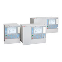
ABB RELION RET670 Installation Manual (112 pages)
Brand: ABB
|
Category: Power distribution unit
|
Size: 4.88 MB
Table of Contents
-
Table of Contents
7
-
Section 1 Introduction
11
-
This Manual
11
-
Intended Audience
11
-
Product Documentation
12
-
Product Documentation Set
12
-
Document Revision History
13
-
Related Documents
14
-
-
Document Symbols and Conventions
16
-
Symbols
16
-
Document Conventions
16
-
-
-
Section 2 Safety Information
19
-
Symbols on the Product
19
-
Warnings
19
-
Caution Signs
21
-
Note Signs
22
-
-
Section 3 Environmental Aspects
23
-
Sustainable Development
23
-
Disposing of the IED
23
-
-
Section 4 Unpacking, Inspecting and Storing
25
-
Removing Transport Packaging
25
-
Inspecting the Product
25
-
Identifying the Product
25
-
Checking Delivery Items
25
-
Inspecting the IED
25
-
Returning an IED Damaged in Transit
26
-
-
Storing
26
-
-
Section 5 Mounting
27
-
Required Tools
27
-
Checking Environmental Conditions and Mounting Space
27
-
Mounting the IED
27
-
Flush Mounting
28
-
Overview
28
-
Mounting Procedure for Flush Mounting
29
-
19″ Panel Rack Mounting
30
-
Overview
30
-
Mounting Procedure for 19″ Panel Rack Mounting
31
-
-
Wall Mounting
32
-
Overview
32
-
Mounting Procedure for Wall Mounting
33
-
How to Reach the Rear Side of the IED
33
-
Side-By-Side 19″ Rack Mounting
34
-
Overview
34
-
Mounting Procedure for Side-By-Side Rack Mounting
35
-
IED Mounted with a RHGS6 Case
35
-
-
Side-By-Side Flush Mounting
36
-
Overview
36
-
Mounting Procedure for Side-By-Side Flush Mounting
37
-
-
Mounting the Injection Unit REX060 (REG670 Only)
37
-
Mounting the Coupling Capacitor Unit REX061 and Shunt Resistor Unit REX062 (REG670 Only)
38
-
Coupling Capacitor Unit REX061
38
-
Shunt Resistor Unit REX062
39
-
-
-
ABB RELION RET670 Installation Manual (102 pages)
Version 2.2 ANSI
Brand: ABB
|
Category: Protection Device
|
Size: 6.22 MB
Table of Contents
-
Table of Contents
7
-
Introduction
11
-
This Manual
11
-
Intended Audience
11
-
Section 1 Introduction
11
-
Product Documentation
12
-
Product Documentation Set
12
-
Document Revision History
13
-
Related Documents
13
-
Document Symbols and Conventions
15
-
Symbols
15
-
Document Conventions
16
-
-
Safety Information
17
-
Symbols on the Product
17
-
Warnings
17
-
Section 2 Safety Information
17
-
Caution Signs
18
-
Note Signs
19
-
-
Environmental Aspects
21
-
Sustainable Development
21
-
Disposing of the IED
21
-
Section 3 Environmental Aspects
21
-
-
Unpacking, Inspecting and Storing
23
-
Removing Transport Packaging
23
-
Inspecting the Product
23
-
Identifying the Product
23
-
Checking Delivery Items
23
-
Inspecting the IED
23
-
Returning an IED Damaged in Transit
23
-
Storing
24
-
-
Mounting
25
-
Required Tools
25
-
Checking Environmental Conditions and Mounting Space
25
-
Mounting the IED
25
-
Section 5 Mounting
25
-
Flush Mounting
26
-
Overview
26
-
Mounting Procedure for Flush Mounting
27
-
19″ Panel Rack Mounting
27
-
Overview
27
-
Mounting Procedure for 19″ Panel Rack Mounting
28
-
Wall Mounting
29
-
Overview
29
-
Mounting Procedure for Wall Mounting
29
-
How to Reach the Rear Side of the IED
29
-
Side-By-Side 19″ Rack Mounting
30
-
Overview
30
-
Mounting Procedure for Side-By-Side Rack Mounting
31
-
IED Mounted with a RHGS6 Case
31
-
Side-By-Side Flush Mounting
32
-
Overview
32
-
Mounting Procedure for Side-By-Side Flush Mounting
33
-
Mounting the Injection Unit REX060 (REG670 Only)
33
-
Mounting the Coupling Capacitor Unit REX061 and Shunt Resistor Unit REX062 (REG670 Only)
34
-
Coupling Capacitor Unit REX061
34
-
Shunt Resistor Unit REX062
35
-

ABB RELION RET670 Product Manual (113 pages)
Transformer protection
Brand: ABB
|
Category: Surge Protector
|
Size: 3.04 MB
Table of Contents
-
Table of Contents
2
-
Application
3
-
Available Functions
4
-
Differential Protection
4
-
Impedance Protection
4
-
Current Protection
5
-
Voltage Protection
5
-
Frequency Protection
5
-
Multipurpose Protection
5
-
Secondary System Supervision
6
-
Control
6
-
Logic
6
-
Monitoring
7
-
Metering
7
-
Basic IED Functions
9
-
Human Machine Interface
24
-
Station Communication
25
-
Remote Communication
26
-
Hardware Description
26
-
Connection Diagrams
30
-
Technical Data
39
-
Ordering
93
ABB RELION RET670 Product Manual (91 pages)
Relion 670 series Transformer protection ANSI
Pre-configured
Brand: ABB
|
Category: Protection Device
|
Size: 4.38 MB
Table of Contents
-
Table of Contents
2
-
Application
3
-
Available Functions
8
-
Differential Protection
8
-
Current Protection
9
-
Voltage Protection
9
-
Frequency Protection
9
-
Multipurpose Protection
9
-
Qcbay
10
-
Secondary System Supervision
10
-
Control
10
-
Logic
10
-
Monitoring
11
-
Metering
11
-
Remote
12
-
Local
13
-
-
Basic IED Functions
13
-
Local
20
-
Local
21
-
-
Human Machine Interface
22
-
Station Communication
23
-
Remote Communication
24
-
Hardware Description
24
-
Remote
25
-
Connection Diagrams
28
-
Technical Data
41
-
Logic SMPPTRC
66
-
Remote
73
-
Local
83
-
-
Ordering
83
-
Remote
86

ABB RELION RET670 Product Manual (102 pages)
Brand: ABB
|
Category: Protection Device
|
Size: 2.79 MB
Table of Contents
-
Table of Contents
2
-
Application
3
-
Available Functions
9
-
Functionality
12
-
Hardware Description
27
-
Connection Diagrams
30
-
Technical Data
42
-
Ordering
90

ABB RELION RET670 Communication Protocol Manual (48 pages)
Brand: ABB
|
Category: Power distribution unit
|
Size: 1.4 MB
Table of Contents
-
Table of Contents
7
-
Introduction
9
-
This Manual
9
-
Intended Audience
9
-
Product Documentation
9
-
Product Documentation Set
9
-
Document Revision History
10
-
Related Documents
11
-
Document Symbols and Conventions
12
-
Symbols
12
-
Document Conventions
13
-
SPA Application
15
-
SPA Communication Protocol
15
-
Application
15
-
Setting Guidelines
16
-
SPA Operation Principle
17
-
Operation Principle
17
-
Introduction of SPA Protocol
17
-
SPA Protocol
17
-
I/O Modules
18
-
Single Command, 16 Signals
18
-
Event Function EVENT
20
-
Connection of Signals as Events
21
-
Communication Ports
22
-
Design
22
-
SPA Settings
25
-
Settings
25
-
SPA Technical Data
27
-
Technical Data
27
-
Establishing Connection and Verifying the SPA/IEC Communication
29
-
Entering Settings
29
-
Entering SPA Settings
29
-
Verifying the Communication
29
-
Verifying SPA Communication
29
-
Fiber Optic Loop
30
-
Optical Budget Calculation for Serial Communication with SPA/IEC
30
-
SPA Functions
31
-
SPA, 670 Series Communication Protocol Manual
31
-
Event Function EVENT
31
-
Identification
31
-
Function Block
31
-
Signals
31
-
Settings
32
-
Operation Principle
34
-
Setting Guidelines
35
-
Eventmask (Ch_1 — 16)
35
-
Lonchannelmask or Spachannelmask
35
-
Minrepintval (1 — 16)
36
-
Logical Signal Status Report BINSTATREP
36
-
Identification
36

ABB RELION RET670 Product Manual (69 pages)
Relion 670 series
Transformer protection 9-2 LE Customized
Brand: ABB
|
Category: Transformer
|
Size: 2.52 MB
Table of Contents
-
Table of Contents
2
-
Application
3
-
Available Functions
8
-
Differential Protection
8
-
Impedance Protection
8
-
Current Protection
8
-
Voltage Protection
8
-
Secondary System Supervision
9
-
Control
9
-
Logic
9
-
Monitoring
9
-
Metering
10
-
Basic IED Functions
11
-
Human Machine Interface
18
-
Station Communication
18
-
Hardware Description
18
-
Connection Diagrams
21
-
Technical Data
26
-
Ordering
59
Advertisement
Related Products
-
ABB RET650 2.1 IEC
-
ABB RET630
-
ABB RET650 2.2
-
ABB RET615
-
ABB RET 670
-
ABB RET670 ANSI
-
ABB RELION REB670
-
ABB RELION REM615
-
ABB REL 352
-
ABB REL650 A11
ABB Categories
Industrial Equipment
Controller
Measuring Instruments
Battery Charger
DC Drives
More ABB Manuals