-
Page 1
REOVIB Control Equipment for the Vibratory Feeder Industry MFS 268 Frequency Converter for Vibratory Feeders UL / CSA — Version 268_UL-CSA_ANL_EN_47-13.DOC 21.11.2013… -
Page 2: Technical Safety Instructions For The User
The units described herein are electrical controllers for installation in industrial plant. They are designed for controlling vibratory feeders. For use in NFPA 79 Applications only Adapters providing field wiring means are available from REO ELEKTRONIK AG. Refer to REO ELEKTRONIK AG.
-
Page 3: Table Of Contents
REOVIB MFS 268 UL/CSA Operating Instructions ELEKTRONIK Contents Technical safety instructions for the user ………………… 1 1.0 General …………………………3 2.0 Function …………………………3 2.1 Track control ……………………….4 2.2 Operating with two speeds (2 set points for coarse/fine switching) ………… 4 2.3 Control inputs and output ……………………
-
Page 4: General
ELEKTRONIK 1.0 General The REOVIB MFS 268 range comprises special, adaptable controllers for use with vibratory feeders. The units generate an output frequency, to drive feeders, that is independent of mains frequency and so exact tuning with springs is not necessary. The feeders also run quieter because of the sinusoidal output signal.
-
Page 5: Track Control
REOVIB MFS 268 UL/CSA Operating Instructions ELEKTRONIK 2.1 Track control output switched ON and OFF Sensor from a track component sensor, using internal, adjustable time delays (ton Feeder and toff). The queue of components rises above and drops below the track sensor…
-
Page 6: Output Status Relay
REOVIB MFS 268 UL/CSA Operating Instructions ELEKTRONIK 2.3.4 Output status relay Status-Relay contact 250 V/1 A (changeover). Relay closes when the feeder is running – the relay opens when there is no enable signal or a fault displayed. 2.3.5 Time-Out output 24 VDC «time Out»…
-
Page 7: Technical Data
For use in NFPA 79 Applications only E217179 Adapters providing field wiring means are available from REO ELEKTRONIK AG. Refer to REO ELEKTRONIK AG. 6.0 Declaration of Conformity We declare that these products conform with the following standards: EN 61000-6-4 and EN 61000-6-2 in accordance with the regulations of guidelines 2004/108/EC.
-
Page 8: Settings
REOVIB MFS 268 UL/CSA Operating Instructions ELEKTRONIK 7.0 Settings After checking the correct operation of the controller in conjunction with the vibratory feed system it is advisable to restrict the user to feeder throughput settings only. Setting the feeder throughput: Press the P key twice and adjust the throughput with the cursor keys (Code C.
-
Page 9: Control Elements
REOVIB MFS 268 UL/CSA Operating Instructions ELEKTRONIK 8.0 Control elements 8.1 Settings The six buttons and a LED display found in the front panel, are used for operating and setting up the unit. All operating methods and adjustable Display parameters can be set up through this panel.
-
Page 10: Commissioning
REOVIB MFS 268 UL/CSA Operating Instructions ELEKTRONIK 9.0 Commissioning 9.1 Assembling position Please fasten the devices on a vibration-free underground and take care for sufficient air circulation. 9.2 Preliminary steps • Check that the unit is correct for the local mains supply (rating plate information) and that it is correct- ly rated for the feed system.
-
Page 11: Putting The Equipment Into Operation
REOVIB MFS 268 UL/CSA Operating Instructions ELEKTRONIK 9.3 Putting the equipment into operation 1. Establish the vibrating frequency. 2. Establish the power of the feed system (maximum permissible current draw). For a new feeder where settings are unknown: (see also comments below) Without connecting the feeder, select parameter FAC in menu C210 (reset factory settings), press the cursor key to reset (SAFE) and press the P key to leave the menu.
-
Page 12: Setting Instructions
REOVIB MFS 268 UL/CSA Operating Instructions ELEKTRONIK 10.0 Setting Instructions 10.1 User adjustment of throughput Code C. 000 Feeder amplitude set point 0…100 % Running mode A further set point code can be found under C002 (for use in coarse/fine operation) Feeder amplitude set point 0…100 %…
-
Page 13: Track Control
REOVIB MFS 268 UL/CSA Operating Instructions ELEKTRONIK 10.2.2 Track control Code C. 167, 007 On time delay 0…60 sec. Off time delay 0…60 sec. 0 = No sensor inverting I = Sensor inverting 0 = Sensor time out not active I = Sensor time out active E.
-
Page 14: Pulse Feed
REOVIB MFS 268 UL/CSA Operating Instructions ELEKTRONIK 10.2.5 Pulse feed Code C. 004, 064 HOP. = 0 = continuous duty HOP. = I = pulse feed On time delay [sec.] Off time delay [sec.] Invert hopper sensor (not active) Running mode 10.2.6 Regulation mode…
-
Page 15: Instructions For Using Regulation Mode
REOVIB MFS 268 UL/CSA Operating Instructions ELEKTRONIK 10.2.6.1 Instructions for using regulation mode • An accelerometer e.g. SW 70 must be fitted to the vibratory feeder in order to run in regulation mode. The accelerometer should have a frequency range corresponding to that of the feeder.
-
Page 16
REOVIB MFS 268 UL/CSA Operating Instructions ELEKTRONIK In regulation mode the magnitude of the output signal has a direct affect on the maximum ampli- tude of the feeder. On bowl feeders it is advisable to fit the sensor as near as possible to the outside diameter and in this… -
Page 17: Relationship Between Acceleration And Amplitude
REOVIB MFS 268 UL/CSA Operating Instructions ELEKTRONIK 10.2.6.3 Relationship between acceleration and amplitude The sensor measures the momentary acceleration of the feeder. It generates a sinusoidal output voltage signal. The acceleration gets higher as the frequency increases. The sensor signal is greater for a higher frequency and lower amplitude than for a low frequency with a higher amplitude.
-
Page 18: Optimisating Controller In Regulation Mode
REOVIB MFS 268 UL/CSA Operating Instructions ELEKTRONIK 10.2.6.6 Optimisating controller in regulation mode Setting the control range 1. In Menu C. 096 set parameter P (Max Limit) to 50 % 2. Set A (Feeder throughput) to 100% 3. Increase limit P from 50% until the required maximum feeder throughput is achieved The full set point adjustment range of 0…100% can now be used…
-
Page 19: Display Actual Current And Frequency
REOVIB MFS 268 UL/CSA Operating Instructions ELEKTRONIK 10.2.7 Display actual current and frequency Code C. 040 Actual current (display only) Actual frequency (display only) Running mode 10.2.8 Save selected parameters Code C. 143 Choose user parameter set Save new parameters Running mode 10.2.9 Recall user or factory settings…
-
Page 20: Error Messages / Error Reset
REOVIB MFS 268 UL/CSA Operating Instructions ELEKTRONIK 11.0 Error messages / ERROR reset Errors are indicated by an alternating code and ERROR display Overload limit Output level exceeded e.g. incorrect frequency setting, coil air- gap to wide. Short circuit trip Faulty coil, short circuit or defective cable..
-
Page 21: Connections For Enclosed Construction (Ip 54): 6-8 A Units
REOVIB MFS 268 UL/CSA Operating Instructions ELEKTRONIK 12.0 Connections for enclosed construction (IP 54): 6-8 A Units Internal connections When a potentiometer is connected parameter POT must be set to I in Menu C003. Status- relay 1 2 3 4…
-
Page 22: Connections For Enclosed Construction (Ip 54): 12 A Units
REOVIB MFS 268 UL/CSA Operating Instructions ELEKTRONIK 12.1 Connections for enclosed construction (IP 54): 12 A Units Internal connections Status relay Time out +24 V Air valve +24 V +24 V Accelerometer SW… INPUT Set point (external) +10V 0(4)…20mA 0…10V…
-
Page 23: Connections For Enclosed Construction (Ip 54): 16 A Units
REOVIB MFS 268 UL/CSA Operating Instructions ELEKTRONIK 12.2 Connections for enclosed construction (IP 54): 16 A Units Internal connections Status relay Time out +24 V Air valve +24 V +24 V Accelerometer SW… INPUT Set point (external) +10V 0(4)…20mA 0…10V…
-
Page 24: Connections For Panel Mounting Construction (Ip 20): 3 A, 6 A, 8 A
REOVIB MFS 268 UL/CSA Operating Instructions ELEKTRONIK 13.0 Connections for panel mounting construction (IP 20): 3 A, 6 A, 8 A REOVIB MFS268 Material-Sensor +24V Enable 12…24V, DC Set point 0…10V 0(4)…20mA R=500 OHM black External INPUT orange SW… + 24V…
-
Page 25: Connections For Panel Mounting Construction (Ip 20): 16A
REOVIB MFS 268 UL/CSA Operating Instructions ELEKTRONIK 13.1 Connections for panel mounting construction (IP 20): 16A line choke Mains L, N, PE / 115V/230V, 50/60HZ Material sensor +24V Enable 12…24V, DC Set point 0(4)…20mA 0…10V SPEED +10V black orange INPUT Accelerometer SW…
-
Page 26: Dimensions For 3 A, 6 A, 8 A Units
REOVIB MFS 268 UL/CSA Operating Instructions ELEKTRONIK 14.0 Dimensions for 3 A, 6 A, 8 A Units Enclosed construction, (IP 54) Ø5,0 REOVIB MFS 268 SPEED www.reo.de Ø5,0 Panel mounting construction, (IP 20) Ø 5,0 Ø 5,0 REOVIB MFS268 REOVIB MFS268 Ø…
-
Page 27: Dimensions Of Enclosed Construction (Ip 54) 12 A
REOVIB MFS 268 UL/CSA Operating Instructions ELEKTRONIK 14.1 Dimensions of enclosed construction (IP 54) 12 A Ø5,0 REOVIB MFS 268 SPEED www.reo.de Ø5,0 14.2 Dimensions of enclosed construction (IP 54) 16 A Ø5,0 REOVIB MFS 268 SPEED www.reo.de Ø5,0…
-
Page 28: Dimensions Of Panel Mounting Construction (Ip 20) 16 A
REOVIB MFS 268 UL/CSA Operating Instructions ELEKTRONIK 14.3 Dimensions of Panel mounting construction (IP 20) 16 A Ø5,0 SPEED +10V Ø5,0…
-
Page 29: A 1.0 Service Appendix
REOVIB MFS 268 UL/CSA Operating Instructions ELEKTRONIK A 1.0 Service appendix ATTENTION ! The settings described in this section relating to the service menu are intended for use by skilled persons because the functions and limits of the feed system can be greatly influenced by their…
-
Page 30
REOVIB MFS 268 UL/CSA Operating Instructions ELEKTRONIK Frequency adjustment range The control unit is supplied with a maximum frequency range of 5…150Hz. Using an adjustable under and over frequency limits, the user range (parameter F) can be restricted to a maximum ratio of 1:4. -
Page 31
REOVIB MFS 268 UL/CSA Operating Instructions ELEKTRONIK Enable Service Mode The actual service menu is accessed by opening the service mode. 0 = Service mode off I = Service mode on Running mode The normal service menu, containing the output current and frequency limit settings, is accessed by opening the service mode. -
Page 32: A 2.0 Accessories / Spare Parts
REOVIB MFS 268 UL/CSA Operating Instructions ELEKTRONIK A 2.0 Accessories / Spare Parts Reo Order Type: Accessories / Spare Parts: Number: Manufacturer Order Number: Harting: 09 20 003 2711 + 19 20 003 1440 + mains input coupling 19 00 000 5082 + 09 20 000 9918…
-
Page 33
REOVIB MFS 268 UL/CSA Operating Instructions ELEKTRONIK… -
Page 34
Headquarters — Germany REO ELEKTRONIK AG Brühler Straße 100 · D-42657 Solingen Tel.: +49 (0)212 8804 0 · Fax: +49 (0)212 8804 188 REO INDUCTIVE COMPONENTS AG Brühler Straße 100 · D-42657 Solingen Tel.: +49 (0)212 8804 0 · Fax: +49 (0)212 8804 188 E-Mail: info@reo.de…
-
Contents
-
Table of Contents
-
Bookmarks
Quick Links
REOVIB
Control Equipment for the Vibratory Feeder Industry
MFS 268
Frequency Converter for Vibratory Feeders
Appendix: EtherNet-IP — Programming
MFS_268_EtherNetIP_appendix_rev03.en
02.08.2016
Related Manuals for REO REOVIB MFS 268
Summary of Contents for REO REOVIB MFS 268
-
Page 1
REOVIB Control Equipment for the Vibratory Feeder Industry MFS 268 Frequency Converter for Vibratory Feeders Appendix: EtherNet-IP — Programming MFS_268_EtherNetIP_appendix_rev03.en 02.08.2016… -
Page 2: Technical Safety Instructions For The User
REOVIB MFS 268 Operating Instructions EtherNet/IP — Programming Technical safety instructions for the user This description contains the necessary information for the correct application of the product described below. It is intended for use by technically qualified personal. Qualified personnel are persons who, because of their training, experience and position as well as their…
-
Page 3: Table Of Contents
REOVIB MFS 268 Operating Instructions EtherNet/IP — Programming Contents Technical safety instructions for the user ………………… 2 1.0 General …………………………4 2.0 Interface operation (EtherNet-IP ) ………………….5 3.0 Activate interface ………………………. 5 4.0 EDS-File …………………………5 5.0 Bus operating modes……………………..5 5.1 Programming for the Bus operation ………………..
-
Page 4: General
REOVIB MFS 268 Operating Instructions EtherNet/IP — Programming 1.0 General The MFS 268 range of frequency converters for vibratory feeders can operate with an EtherNet-IP inter- face. In normal operation the set point, for the feeder throughput, can be sent from a PLC to the controller and the unit ready/fault status signals are fed back.
-
Page 5: Interface Operation (Ethernet-Ip )
REOVIB MFS 268 Operating Instructions EtherNet/IP — Programming 2.0 Interface operation (EtherNet-IP ) Bus Power Supply 24 V, DC, 250 mA Bus connector 2 x RJ-45 Internal interface CAN-Bus Supported baud rates 1000 kBaud Communication Data consistency required Protocol EtherNet-IP 3.0 Activate interface…
-
Page 6: Programming For The Bus Operation
REOVIB MFS 268 Operating Instructions EtherNet/IP — Programming 5.1 Programming for the Bus operation In normal operation the set point for Amplitude (throughout/feed rate) and the digital control signals, such as enable are set across the interface. The actual voltage/current values and unit status (ready or fault) are fed back.
-
Page 7: Parameter Operation
REOVIB MFS 268 Operating Instructions EtherNet/IP — Programming 5.2 Parameter Operation In parameter operation, the specific unit parameters can be monitored and adjusted. A `write` enable must be transmitted before parameters can be altered. On closing, the `write` enable must be cancelled.
-
Page 8: Receive, Acknowledge Write Enable
REOVIB MFS 268 Operating Instructions EtherNet/IP — Programming 5.2.3 Receive, Acknowledge Write Enable H-Byte L-Byte Word 1 xxxx H (undefined) H-Byte L-Byte Word 2 C0DE H H-Byte L-Byte Word 3 B5E7 H H-Byte L-Byte Word 4 C0DE H The parameters can be sent after receipt of the acknowledge 5.2.4 Send Parameter…
-
Page 9: Close Write Enable
REOVIB MFS 268 Operating Instructions EtherNet/IP — Programming 5.2.5 Close write enable H-Byte L-Byte Wort d 0000 H H-Byte L-Byte Word 2 Write Enable Address = C0DE H H-Byte L-Byte Word 3 Enable Value 0000 H-Byte L-Byte Word 4 15 14 13 12 11 10 9…
-
Page 10: Parameter Table
REOVIB MFS 268 Operating Instructions EtherNet/IP — Programming 6.0 Parameter Table Non listed addresses cannot be altered! Parameter: Adjustment Display- Factory Entry Parameter Value Code Setting: code address HEX (.bit) Vibratory feeder 0x0000…0xFFFF 0…100 % 000, 100C Amplitude (throughput) •…
-
Page 11
REOVIB MFS 268 Operating Instructions EtherNet/IP — Programming Parameter: Adjustment Display- Factory Entry Parameter Value Code Setting: code address HEX (.bit) Service limits 0x0000 / 0x FFFF 0 / I En.S. 0x5834 • Enable service menu 0x0000…0x8000 H 0x200A • Show output current (0… 100 %) 0x01F4…0x7530 H… -
Page 12: Example Of Bus Communication With Frequency Controller
REOVIB MFS 268 Operating Instructions EtherNet/IP — Programming 7.0 Example of bus communication with Frequency controller Variable values are shown in italics. 7.1 Normal mode (Set point to 70 %) Word Code send Code Received 0000 H 0000 H B332 H…
-
Page 13
REOVIB MFS 268 Operating Instructions EtherNet/IP — Programming Example of switch parameter change Enable invert send Received Word Code Code 0000 H 0000 H C0DE H Write Enable Address C0DE H Acknowledge B5E7 H Write Enable Value B5E7 H Acknowledge… -
Page 14: Reset Controller
REOVIB MFS 268 Operating Instructions EtherNet/IP — Programming 7.3 RESET Controller Word Code send Code received 0000 H 0000 H C0DE H Write Enable Address C0DE H Acknowledge B5C9 H Write Enable Value B5C9 H Acknowledge 8000 H + Set mode bit = 1…
-
Page 15: Methods For Adjusting The Ip-Address
REOVIB MFS 268 Operating Instructions EtherNet/IP — Programming 8.0 Methods for adjusting the IP-address 1. Web server (Preferably) 2. DHCP Server Utility If you don’t have a browser, you can push a switch on the front of our device. If you push this switch shorter than five seconds, the device gets the IP-address 192.168.11.182.
-
Page 16
REOVIB MFS 268 Operating Instructions EtherNet/IP — Programming 5. Then you double-click on „Internet Protocol Version 4 (TCP/IPv4)“ 6. Then you set the subnet mask at 255.255.240.0. 7. You click on „OK“. 8. Then you open the web browser (e.g. the Internet-Explorer). -
Page 17: Dhcp Server Utility (Example: „Bootp/Dhcp Server»)
REOVIB MFS 268 Operating Instructions EtherNet/IP — Programming 8.2 DHCP Server Utility (Example: „BOOTP/DHCP Server“) 1. Please download a DHCP Server software for example: „DHCP/BOOTP Utility“. Important: Before you start the DHCP-server, note the MAC-address which has the following form: 00-00-BC-14-55-35. The MAC-address stands on the front of the module.
-
Page 18
REOVIB MFS 268 Operating Instructions EtherNet/IP — Programming… -
Page 19
REOVIB MFS 268 Operating Instructions EtherNet/IP — Programming… -
Page 20
REO Shanghai Inductive Components Co., Ltd No. 536 ShangFeng Road · Pudong, 201201 Shanghai · China REO Vibratory Feeding and Power Electronics Division Tel.: +86 (0)21 5858 0686 · Fax: +86 (0)21 5858 0289 Brühler Straße 100 · D-42657 Solingen E-Mail: info@reo.cn ·…
300,00 $ — 800,00 $/ шт. |1 шт./шт.(Мин. заказ)
Время выполнения заказа:
| Quantity (шт.) | 1 — 20 | 21 — 100 | 101 — 500 | > 500 |
| Примерное время (в днях) | 3 | 4 | 5 | Подлежит согласованию |
Изготовление на заказ:
Эмблема на заказ(Мин. заказ 1 шт.)
Индивидуализированная упаковка(Мин. заказ 1 шт.)
Графические настройки(Мин. заказ 1 шт.)
Сведения о покупке
Защита с помощью
Транспортировка:
Связаться с поставщиком для согласования деталей доставки
Для вас Гарантия своевременной отправки
Платежи:
Шифрование и повышенная безопасность платежей Подробнее
Возврат товаров и возмещение средств
Eligible for refunds within 30 days of receiving products. Подробнее
Покупайте с уверенностью
 Проверен как производитель товаров по индивидуальному заказу

Complete catalog
Download our extensive catalog and discover many other REO products.

Datenblatt
Alle Daten und Konfigurationen finden Sie in unserem Produktdatenblatt.
Certifications
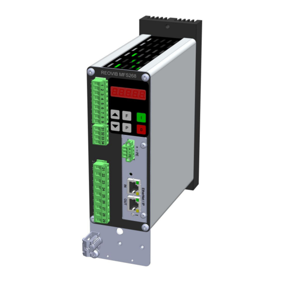
FREQUENCY CONVERTER REOVIB MFS 168
IP 54 or IP 20
Description
Frequency converters in the REOVIB MFS 158 and
REOVIB MFS 168 series for vibratory conveyor technology offer the option of operating the vibratory conveyor at an optimal vibration frequency for the material – completely independently of the mains input frequency.
Devices in the REOVIB MFS 158 series are available with a max. output current of 4 A and the Devices in the
REOVIB MFS 168 series are available with a max. output current of 3 A, 6 A and 8 A. Both series are available as IP20 versions for installation in control cabinets or as IP54 standalone units.
The IP54 housings are available with various connection options:
- Input cable/output cable
- Input cable/output socket
- Complete cable connection solution for mains, output and control connections
Advantages
- Inexpensive frequency-control devices with the vital functionality
- Frequency-control device for controlling a vibratory conveyor independently of the mains input frequency
- Conveyor frequencies adjustable between 35…140 Hz
- Mains voltage compensation with constant vibration amplitude
- All settings can be made using the integrated display
- Sinusoidal output current
- Can be used on 110 V or 240 V mains, auto sensing.
- User settings can be stored
- With fill level/overflow control
- Versions available in various protection classes and with various connection options
- REOVIB MFS 168: Automatic detection of the resonant frequency of the vibratory conveyor system (with additional vibration amplitude sensor) and option to regulate the vibration amplitude – Constant feed rates can be achieved independently of load or changes in the mechnical system
Technical specifications

Suitable for this product

AC Magnets

Accelerometers
Contact
Contact and product inquiry
We are there for you
Do you have questions, requests or suggestions?
Please don’t hesitate to contact us:
REO AG
Brühler Strasse 100
D-42657 Solingen
Tel.: 0049-(0)2 12-88 04-0
Fax: 0049-(0)2 12-88 04-188
E-Mail: info@reo.de
USt-ID-Nr.: DE 182 486 130
St.-Nr.: 128/5819/5634
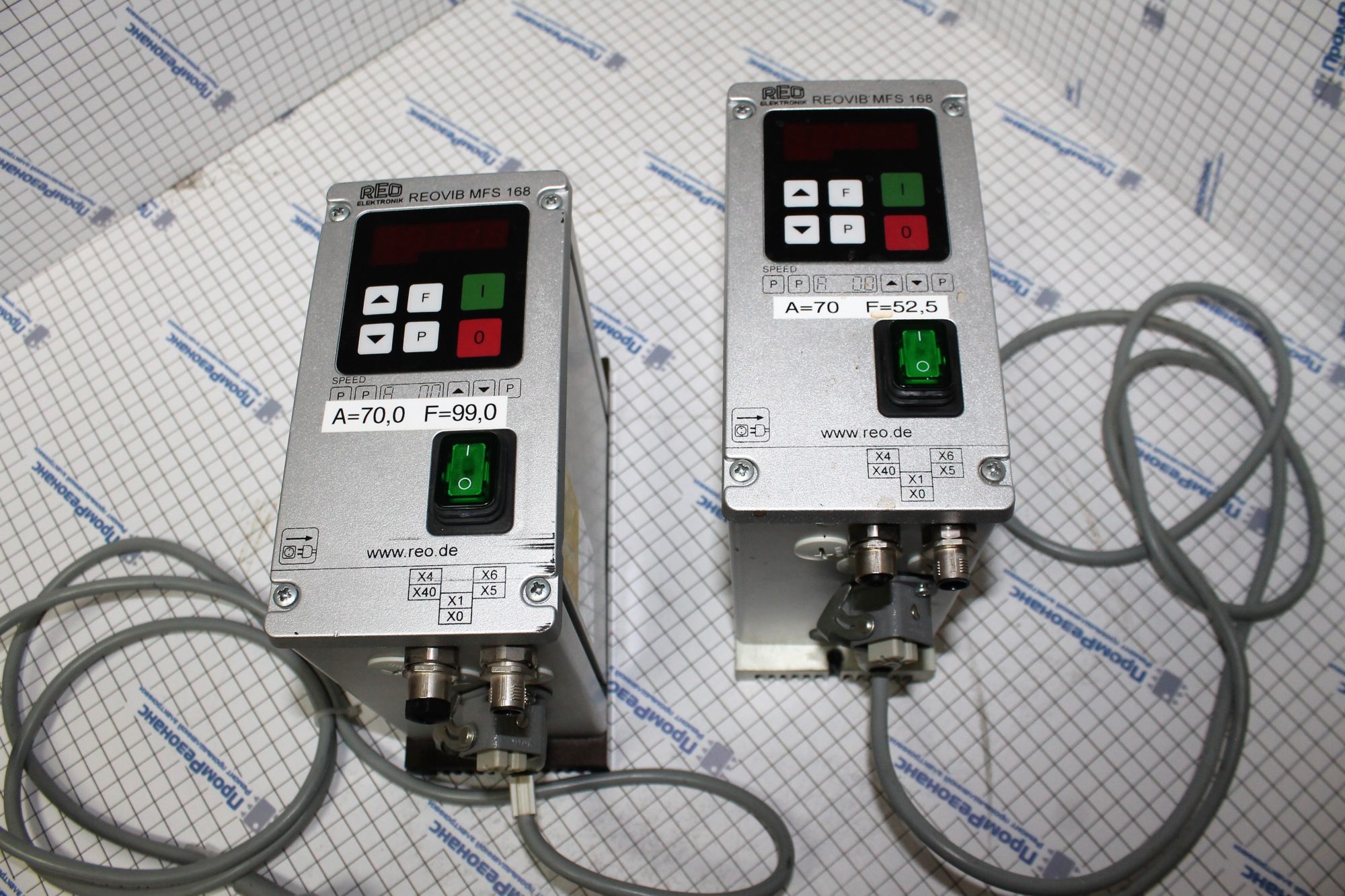
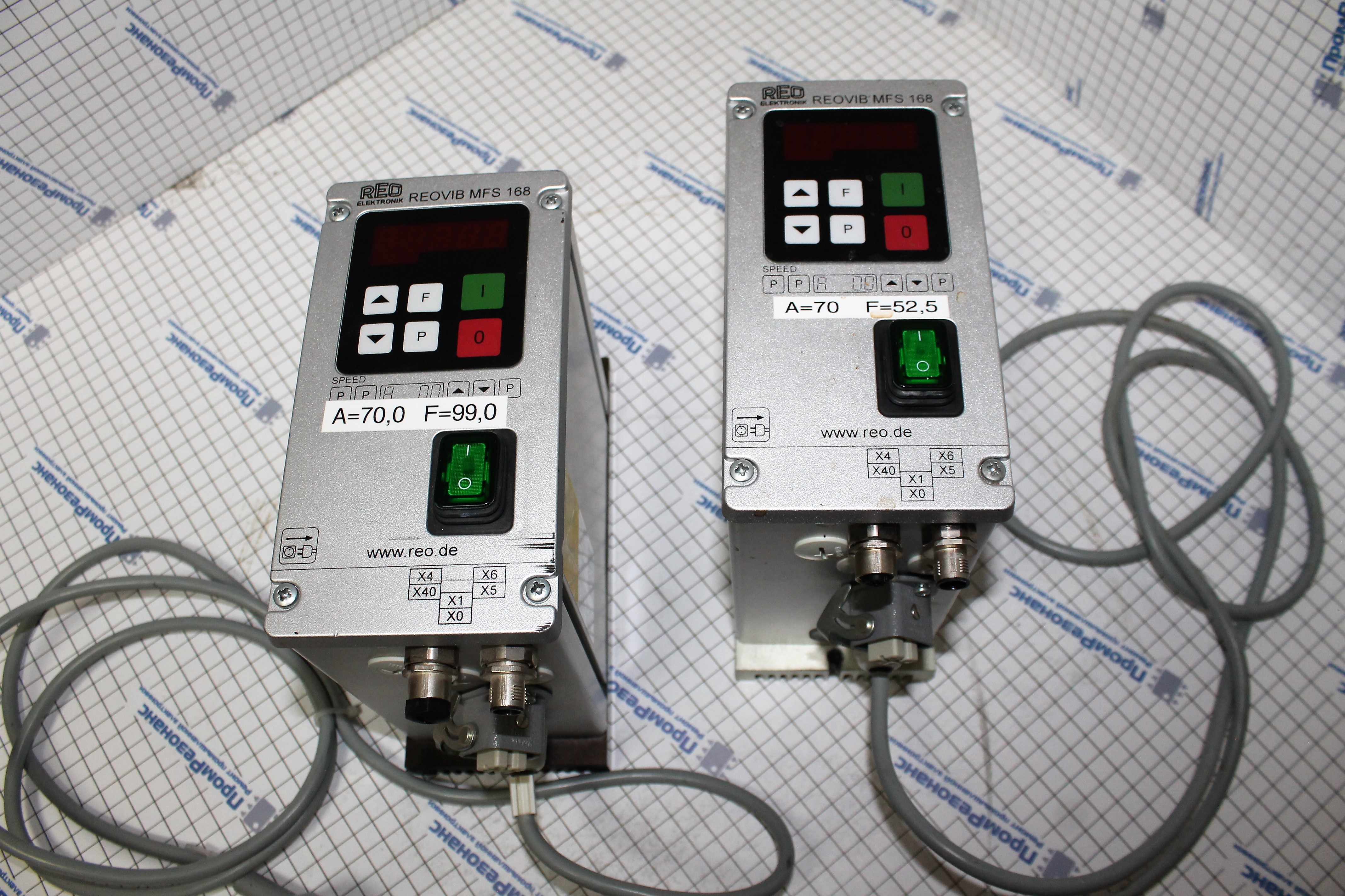
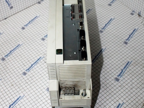
Ремонт частотного преобразователя. Ремонт на уровне компонентов.
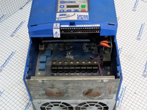
Вы смотрите:Частотный преобразователь REO Reovib MFS 168
Выполненные ремонты
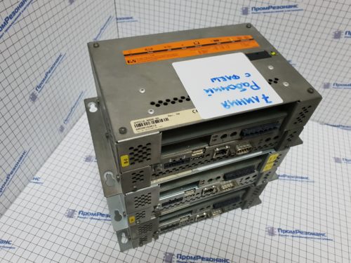
Контроллер питания B&R 4PP210.0000-95
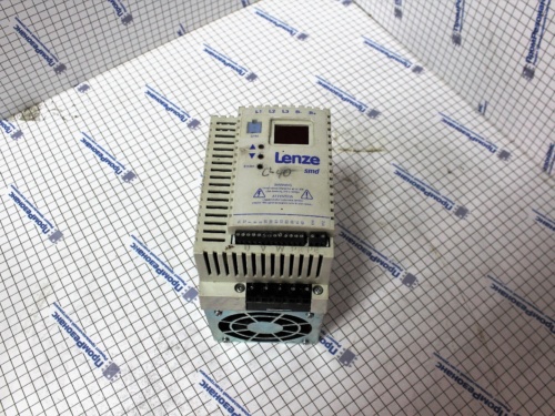
Частотный преобразователь Lenze EVS9324-EP Lecom B
Сервопривод Parker Servoregler 638A 638A063F0STO000000RM1
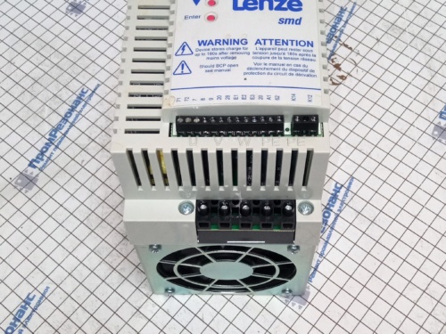
Частотный преобразователь Lenze ESMD552L4TXA
Частотный преобразователь Siemens 6SL3224-0BE24-0AA0
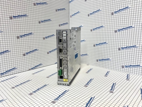
Сервопривод YASKAWA SERVOPACK SGDB-15VNY1
Частотный преобразователь Lenze AC Tech ESV303N04TXB
Промышленный монитор MultiQ MQ172
Контроллер погрузчика ZAPI C15296 / A4H248
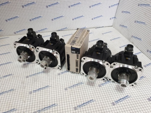
Сервомотор Yaskawa SGM7G-09AFC61
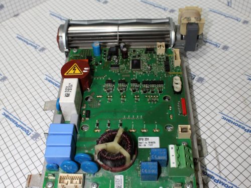
Модуль управления для стиральной машины Miele EFU 231 Nr.:7018670
Инвертор Mastervolt AC Master 24/2500
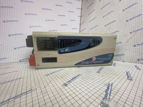
Инвертор Any Power combi 612-00099-00 AP
Частотный преобразователь Lenze ESMD552L4TXA
Частотный преобразователь IDS Drive Z153T4B
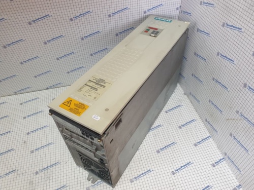
Блок питания частотных регуляторов Siemens Simovert 6SE7028-6EC85-1AA0
Преобразователи частоты Fuji-Electric FRN0059E2E-4E
Частотный преобразователь Baumuller BM4434-SI1-01200-03
Электронный регулятор Danfoss ECL Comfort 310