Руководство на испанском языке по техническому обслуживанию и ремонту автомобиля Renault Master Propulsion.
- Автор: —
- Издательство: Renault
- Год издания: 2005
- Страниц: —
- Формат: PDF
- Размер: 6,1 Mb
Руководство на испанском языке по техническому обслуживанию и ремонту автомобиля Renault Master первого поколения.
- Автор: —
- Издательство: Renault
- Год издания: —
- Страниц: —
- Формат: PDF
- Размер: 6,7 Mb

Сборник руководств по техническому обслуживанию и ремонту автомобиля Renault Master 1997-2003 годов выпуска.
- Автор: —
- Издательство: Renault
- Год издания: 2001-2003
- Страниц: —
- Формат: PDF
- Размер: 34,9 Mb

Руководство по эксплуатации ремонту автомобилей Renault Laguna Master Propulsion и Renault Mascott 2001-2010 годов выпуска с дизельными двигателями объемом 3,0 литра.
- Автор: —
- Издательство: Гуси-Лебеди
- Год издания: —
- Страниц: 328
- Формат: —
- Размер: —

Руководство по эксплуатации и ремонту автомобилей Nissan Interstar, Renault Master и Opel/Vauxhall Movano с 1998 года выпуска с дизельными двигателями.
- Автор: —
- Издательство: Монолит
- Год издания: —
- Страниц: 434
- Формат: —
- Размер: —
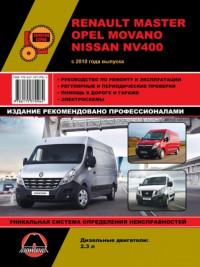
Руководство по эксплуатации и ремонту автомобилей Nissan NV400, Opel Movano и Renault Master с 2010 года выпуска с дизельным двигателем объемом 2,3 л.
- Автор: —
- Издательство: Монолит
- Год издания: 2012
- Страниц: 227
- Формат: PDF
- Размер: 97,1 Mb

Руководство по эксплуатации и ремонту автомобилей Nissan NV400, Opel Movano и Renault Master с 2010 года выпуска с дизельным двигателем объемом 2,3 л.
- Автор: —
- Издательство: Монолит
- Год издания: —
- Страниц: 234
- Формат: —
- Размер: —

Руководство по эксплуатации и техническому обслуживанию автомобиля Renault Master 2011 года выпуска.
- Автор: —
- Издательство: Renault
- Год издания: —
- Страниц: 241/21
- Формат: PDF
- Размер: 8,0 Mb
Сборник мультимедийных схем на нескольких языках (в том числе русском) электрооборудования автомобиля Renault Master 2000-2008 годов выпуска.
- Автор: —
- Издательство: Renault
- Год издания: —
- Страниц: —
- Формат: ISO
- Размер: 978,6 Mb

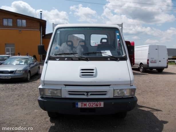
Renault Master T35D

FT-MK2
Был больше месяца назад
Artur, 27 лет
Я езжу на Renault Master 2,8TDI и Ford Transit 2.5DI Ex camper (до этого — Renault Master)
Львов, Украина
Ура свершилось, нашел я мануал на свое Лего, перечитал много полезного нашел))
Сылочка на скачивание
Цена вопроса: 10 €
22 марта 2014
Метки: аксессуары
39
14
Ранее О запчастях на Renault Master I
Далее Смена внешности
Разместить рекламу
Реклама
Машины в продаже

Шахты
Renault Logan, 2020
790 000 ₽

Шахты
Renault Sandero, 2014
750 000 ₽

Шахты
Renault Symbol, 2011
649 000 ₽

Сальск
Renault Fluence, 2015
999 900 ₽
Посмотреть больше машин на Дроме
Комментарии
14
Войдите или зарегистрируйтесь, чтобы писать комментарии, задавать вопросы и участвовать в обсуждении.
Войти
Зарегистрироваться

Andyfirst
Без машины
К стати у меня задние фонари от запора — глянь на фотках.Ставь и не парся (новые 100 грн.)
9 лет

FT-MK2
Автор
Я езжу на Renault Master (2G)
та нее.я хочу родные
9 лет
Andyfirst
Без машины
У меня к нему ничего нет — но мне написал один человек в комментариях объявлению что продает по запчастям 0675878452 — Виталя. Попробуй.Но я ему не набирал.
9 лет
FT-MK2
Автор
Я езжу на Renault Master (2G)
спс, попробую звякнуть.
9 лет
Andyfirst
Без машины
Есть — но на сайте его нету. Сейчас на продаже.poltava.pol.slando.ua/oby…er-gruz-1994-ID8Kif9.html На Тойоте к стати тоже есть )))) СПС за мануал — редкая вещь
9 лет
FT-MK2
Автор
Я езжу на Renault Master (2G)
не за что)
слушай а у тебя запчастей на реноху не осталось?правая дверца, пружины, рейка ГУР ?задние фонари
9 лет
Andyfirst
Без машины
Спасибо ! К стати круиз и у меня есть…так что опция популярная была
9 лет
FT-MK2
Автор
Я езжу на Renault Master (2G)
на тойоте? или у вас тоже мастерок есть?..
9 лет

itrij
Я езжу на Renault Trafic (2G)
Поздравляю с находкой!
9 лет
FT-MK2
Автор
Я езжу на Renault Master (2G)
большое спасибо))
9 лет
somebody
Несуществующий пользователь
Без машины
А как скачать то? )
9 лет
FT-MK2
Автор
Я езжу на Renault Master (2G)
крути вниз, там будет »ссилка на скачиване»
9 лет

999black
Я езжу на Nissan Skyline (R33)
Какой смешной )))
9 лет
FT-MK2
Автор
Я езжу на Renault Master (2G)
милый))
9 лет
Other Manuals
36 Pages
Dishwashers — Champion — Taskmaster — PP3
View pdf
£9.99
Get your hands on the complete Renault factory workshop software
Download now
Other Manuals
10 Pages
Software — Apple — Compressor or Qmaster Batch Monitor User Manual
View pdf
Other Manuals
44 Pages
Dishwashers — Champion — Taskmaster Power Wash Sink System — PP-3
View pdf
Other Manuals
11 Pages
Harley Davidson — Motorcycle — Harley_Davidson_MasterCamSpecs
View pdf
Best iPad Holder For Car
Find out more
Other Manuals
1 Pages
Toys & Accessories — Fisher-Price — TrackMaster R~C Luke — (DFN14)
View pdf
Other Manuals
25 Pages
Software — Apple — Apple Qmaster 2 User Manual
View pdf
Other Manuals
12 Pages
Faucets — Hansgrohe — Clubmaster 3-Jet Showerhea
View pdf
Best Back Seat Organizer
Find out more
Other Manuals
4 Pages
Grills & Accessories — Broilmaster Premium Grills — Smoker Shutter
View pdf
Other Manuals
24 Pages
BMW — Motorcycle — BMW_R51-R61-R66-R71_Baumaster_manual
View pdf
£9.99
Get your hands on the complete Renault factory workshop software
Download now
Other Manuals
20 Pages
Grills & Accessories — Blue Rhino — GBT702W (Range Master)
View pdf
Best Car Creepers
Find out more
Other Manuals
24 Pages
Grills & Accessories — Broilmaster Premium Grills — Carts and Posts
View pdf
Other Manuals
24 Pages
Water Heaters — Haywood-Pool — HeatMaster Heat Pumps~R-22 Models
View pdf
Other Manuals
34 Pages
Software — Apple — Apple Qmaster 4 — User Manual
View pdf
Best Tesla Model 3 Floor Mats
Find out more
Other Manuals
2 Pages
Toys & Accessories — Fisher-Price — PS2 FPS Master — (I3600)
View pdf
Other Manuals
1 Pages
Toys & Accessories — Fisher-Price — TrackMaster Reptile Park Set
View pdf
Other Manuals
10 Pages
Software — Apple — Late-Breaking News About Qmaster 2.3.1
View pdf
Best Bug Remover For Cars
Find out more
Other Manuals
20 Pages
Toys & Accessories — Nintendo — Nintendo DS — Master of Illusion
View pdf
£9.99
Get your hands on the complete Renault factory workshop software
Download now
Other Manuals
3 Pages
Toys & Accessories — Fisher-Price — Castmaster Fishing — (I3012)
View pdf
Other Manuals
1 Pages
Toys & Accessories — Fisher-Price — XBOX FPS Master — (I3240)
View pdf
Best Rear view Mirror In 2021 – Reviews and Buying Guide
Find out more
Other Manuals
14 Pages
Grills & Accessories — Broilmaster Premium Grills — Front Shelf Kit
View pdf
Other Manuals
2 Pages
Toys & Accessories — Mega — hot-wheels — Master Crusher, CNH41
View pdf
Other Manuals
28 Pages
Water Heaters — Haywood-Pool — HeatMaster Heat Pumps~R-410A Models
View pdf
Best Car Tissue Holder
Find out more
Other Manuals
10 Pages
Toys & Accessories — Nintendo — Nintendo DS — Sudoku Gridmaster
View pdf
Other Manuals
32 Pages
Toys & Accessories — Fisher-Price — Kubros Master Chief — DPH88
View pdf
Other Manuals
20 Pages
TNG — Motorcycle — TNG_master_gy6_VL_eng_150CC_3
View pdf
Best Windshield Repair Kit
Find out more
1997
Other Manuals
5 Pages
Renault — Master — Workshop Manual — 1997 — 1997
View pdf
£9.99
Get your hands on the complete Renault factory workshop software
Download now
2004
Brochure
28 Pages
Renault — Master — Sales Brochure — 2004 — 2004
View pdf
£9.99
Get your hands on the complete Renault factory workshop software
Download now
2008
Other Manuals
9 Pages
TNG — Motorcycle — TNG_GY6_Master_VL_eng_150CC_3_2008_
View pdf
£9.99
Get your hands on the complete Renault factory workshop software
Download now
2011
Brochure
9 Pages
Renault — Master — Sales Brochure — 2011 — 2011 (2)
View pdf
£9.99
Get your hands on the complete Renault factory workshop software
Download now
Brochure
22 Pages
Renault — Master — Sales Brochure — 2011 — 2011
View pdf
Brochure
44 Pages
Renault — Master — Sales Brochure — 2011 — 2011 (4)
View pdf
Brochure
11 Pages
Renault — Master — Sales Brochure — 2011 — 2011 (3)
View pdf
Best iPad Holder For Car
Find out more
2012
Other Manuals
185 Pages
Utilimaster — Reach — Parts Catalogue — 2012 — 2012
View pdf
£9.99
Get your hands on the complete Renault factory workshop software
Download now
2013
Brochure
48 Pages
Renault — Master — Sales Brochure — 2013 — 2013
View pdf
£9.99
Get your hands on the complete Renault factory workshop software
Download now
2014
Brochure
56 Pages
Renault — Master — Sales Brochure — 2014 — 2014
View pdf
£9.99
Get your hands on the complete Renault factory workshop software
Download now
Brochure
19 Pages
Renault — Master — Sales Brochure — 2014 — 2014 (2)
View pdf
2015
Other Manuals
268 Pages
Renault — Auto — renault-master-2015-69141
View pdf
£9.99
Get your hands on the complete Renault factory workshop software
Download now
Other Manuals
284 Pages
Renault — Master — Owners Manual — 2015 — 2015
View pdf
Other Manuals
155 Pages
Renault — Auto — renault-master-2015-manual-do-proprietario-90683
View pdf
Brochure
14 Pages
Renault — Master — Sales Brochure — 2015 — 2015
View pdf
Best iPad Holder For Car
Find out more
Other Manuals
2 Pages
Toys & Accessories — Fisher-Price — Buckmaster Huntin’3 — (I2015)
View pdf
2016
Other Manuals
286 Pages
Renault — Master — Owners Manual — 2016 — 2016
View pdf
£9.99
Get your hands on the complete Renault factory workshop software
Download now
Other Manuals
7 Pages
Renault — Master — Miscellaneous Documents — 2016 — 2016
View pdf
Other Manuals
5 Pages
Renault — Master — Miscellaneous Documents — 2016 — 2016 (2)
View pdf
Brochure
36 Pages
Renault — Master — Sales Brochure — 2016 — 2016 (2)
View pdf
Best iPad Holder For Car
Find out more
Other Manuals
448 Pages
Ram — Auto — ram-promaster-2016-owner-s-manual-72781
View pdf
Brochure
9 Pages
Renault — Master — Sales Brochure — 2016 — 2016 (6)
View pdf
Brochure
24 Pages
Renault — Master — Sales Brochure — 2016 — 2016 (5)
View pdf
Best Back Seat Organizer
Find out more
Brochure
18 Pages
Renault — Master — Sales Brochure — 2016 — 2016 (3)
View pdf
Brochure
64 Pages
Renault — Master — Sales Brochure — 2016 — 2016
View pdf
£9.99
Get your hands on the complete Renault factory workshop software
Download now
Other Manuals
145 Pages
Ram — Auto — ram-promaster-2016-diesel-supplement-78922
View pdf
Best Car Creepers
Find out more
Brochure
25 Pages
Renault — Master — Sales Brochure — 2016 — 2016 (4)
View pdf
Other Manuals
164 Pages
Ram — Auto — ram-promaster-2016-guide-d-utilisateur-72840
View pdf
2017
Other Manuals
286 Pages
Renault — Auto — renault-master-2017-betriebsanleitung-106184
View pdf
£9.99
Get your hands on the complete Renault factory workshop software
Download now
Brochure
48 Pages
Renault — Master — Sales Brochure — 2017 — 2017
View pdf
Brochure
31 Pages
Renault — Master — Sales Brochure — 2017 — 2017 (2)
View pdf
2018
Other Manuals
381 Pages
Ram — Auto — ram-promaster-2018-manuel-du-proprietaire-110837
View pdf
£9.99
Get your hands on the complete Renault factory workshop software
Download now
Brochure
60 Pages
Renault — Master — Sales Brochure — 2018 — 2018
View pdf
-
Contents
-
Table of Contents
-
Troubleshooting
-
Bookmarks
Related Manuals for Renault MASTER
Summary of Contents for Renault MASTER
-
Page 1
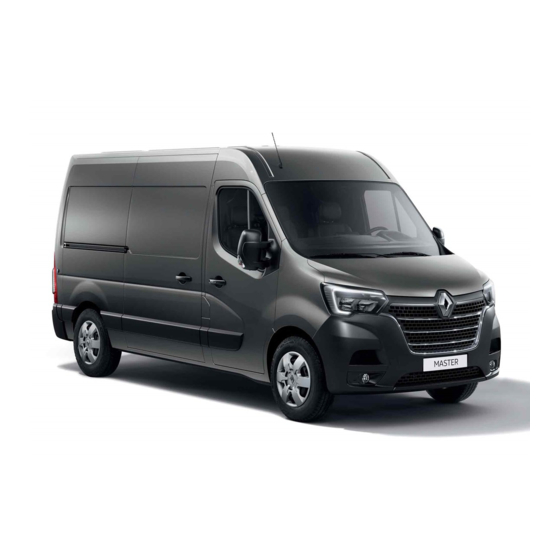
Renault MASTER Vehicle user manual… -
Page 3
Welcome to your new vehicle This driver’s handbook contains the information necessary: – for you to familiarise yourself with your vehicle, to use it to its best advantage and to benefit fully from the all the functions and the technical developments it incorporates. –… -
Page 4
ExTErior Electric windows ➥ 3.17 Windscreen wipers ➥ 1.107 and ➥ 5.38 Bodywork mainte- Demisting ➥ 3.4 and ➥ 3.7 nance ➥ 4.14 Rear view mirrors ➥ 1.105 Key/Remote control ➥ 1.2 Transmitter/receiver ➥ 1.8 Locking/unlocking the doors ➥ 1.10 Lights: operation ➥… -
Page 5
PassEngEr comParTmEnT Adjusting your driving po- Passenger compartment stor- sition ➥ 1.23 age/fittings ➥ 3.23 Rear bench seat ➥ 3.29 Rear headrests ➥ 1.19 Front seats ➥ 1.20 Front headrests ➥ 1.19 Child safety ➥ 1.40 Transporting objects ➥ 3.32… -
Page 6
DrivEr’s PosiTion Trip computer controls Instrument panel ➥ 1.86 ➥ 1.100 Exterior lighting ➥ 1.110 Multimedia screen ➥ 1.92 Heating/Air conditioning system ➥ 3.4 Telephone charging zone ➥ 3.23 Bonnet release ➥ 4.2 Cruise control ➥ 2.45 Speed limiter ➥ 2.42 Steering wheel adjust- ment ➥… -
Page 7: Driving Aids
Driving aiDs ABS (anti-lock braking system) Speed limiter ➥ 2.42 ESC (electronic stability control) Braking assistance Active emergency braking Hill start assistance ➥ 2.20 Cruise control ➥ 2.45 Lane departure warning ➥ 2.32 Parking distance control ➥ 2.50 Blind spot warning ➥ 2.36 Reversing camera ➥…
-
Page 8
safETy on boarD Seat belts ➥ 1.23 Front Airbags ➥ 1.28 Inhibiting the front passen- ger airbag ➥ 1.78 Side Airbags ➥ 1.33… -
Page 9
iDEnTifying a vEhiclE — labEls Review of a vehicle identification number ➥ 6.2 Vehicle identification plate ➥ 6.2 Engine identification plate ➥ 6.4 Tyre pressure labels ➥ 2.29 ➥ 4.11… -
Page 10
ThE EnginE comParTmEnT (routine maintenance) Engine oil filler cap ➥ 4.6 Engine oil dipstick ➥ 4.4 Brake fluid ➥ 4.8 Battery ➥ 4.13 Coolant level ➥ 4.8 Opening the bonnet ➥ 4.2 Windscreen washer fluid ➥ 4.8… -
Page 11
brEakDown rEcovEry Replacing windscreen wiper Puncture: blade(s) ➥ 5.38 Tools ➥ 5.4 Emergency spare wheel ➥ 5.2 Changing wheel ➥ 5.16 R e p l a c i n g headlight bulbs ➥ 5.21 Front towing point ➥ 5.39 Replacing rear light bulbs ➥… -
Page 12
0.10… -
Page 13
sections getting to know your vehicle ……. Driving …………..your comfort …………maintenance …………Practical advice ………… Technical specifications ……..alphabetical index ……….0.11… -
Page 14
0.12… -
Page 15: Table Of Contents
Section 1: Getting to know your vehicle Key, remote control …………. . Deadlocking .
-
Page 16
kEy, raDio frEQUEncy rEmoTE conTrol: general information (1/3) Driver’s responsibility when parking or stopping the vehicle Never leave an animal, child or adult who is not self-suffi- cient alone on your vehicle, even for a short time. They may pose a risk to themselves or to others by starting the engine, radio frequency remote radio frequency remote… -
Page 17
kEy, raDio frEQUEncy rEmoTE conTrol: general information (2/3) radio frequency remote control operating range This varies according to the environ- ment: take care not to lock or unlock the doors by inadvertently pressing the buttons on the remote control. note: on certain vehicles, if a door is not opened within approximately 2 min- utes of the door being unlocked by remote control, the doors will lock again… -
Page 18
kEy, raDio frEQUEncy rEmoTE conTrol: general information (3/3) Driver’s responsibility replacement, additional remote when parking or stopping control or transmitter/receiver the vehicle You must only contact an approved Never leave an animal, Dealer. child or adult who is not self-suffi- –… -
Page 19: Locking The Doors
kEy, raDio frEQUEncy rEmoTE conTrol: use (1/2) To lock/unlock the doors from the inside ➥ 1.10. Driver’s responsibility when parking or stopping the vehicle Never leave an animal, child or adult who is not self-suffi- cient alone in your vehicle, even for a short time.
-
Page 20
kEy, raDio frEQUEncy rEmoTE conTrol: use (2/2) Unlocking the doors Pressing button 2 unlocks the doors and tailgate. A short press on button 3 locks/unlocks the tailgate and, depending on the ve- hicle, the sliding side doors. The un- locking is confirmed by one flash of the hazard warning lights and the side indicator lights. -
Page 21: Deadlocking
DEaDlocking To activate deadlocking If fitted to the vehicle, this allows the doors to be locked and prevents them Press button 1 twice in quick succes- from being opened with the interior sion. handles (for example, by breaking the The side indicator lights and hazard window and then trying to open the warning lights flash five times to indi- doors from the inside).
-
Page 22: Hands-Free Access Transmitter, Receiver
hanDs-frEE accEss TransmiTTEr, rEcEivEr: use (1/2) Driver’s responsibility when parking or stopping the vehicle Never leave an animal, child or adult who is not self-suffi- cient alone on your vehicle, even for a short time. They may pose a risk to themselves or to others by starting the engine, For vehicles equipped with transmitter/ It is powered by a battery which can be…
-
Page 23: Locking The Vehicle
hanDs-frEE accEss TransmiTTEr, rEcEivEr: use (2/2) interference Unlocking the vehicle locking the vehicle Interference by factors in the imme- With the transmitter/receiver in one With the transmitter/receiver in one diate vicinity (external installations or of the access zones 2, press button 3 of the access zones 2, press button 3 the use of equipment operating on the or 4: all of the doors will unlock.
-
Page 24: Locking, Unlocking The Doors
locking, Unlocking ThE Doors (1/2) if the remote control does not work in some cases, the radio frequency remote control may not work: – radio frequency remote control bat- tery worn out or vehicle battery dis- charged, etc. – due to the use of electronic devices near to the remote control (e.g.
-
Page 25: Indicator Light
locking, Unlocking ThE Doors (2/2) locking the opening locking the doors with the elements without the remote tailgate open control To lock the vehicle leaving a door open (e.g. when transporting something in with the engine off, the rear doors the luggage compartment which pre- closed and a front door open,, press vents it from being closed), or when…
-
Page 26
raiD (aUTomaTic locking whEn Driving) activating/deactivating the operating faults function If you experience an operating fault (no automatic locking, switch indica- To activate it: with the ignition on, tor light 1 does not light up when trying press switch 1 for approximately five to lock the opening elements etc.), first seconds until you hear a beep. -
Page 27
fronT Doors (1/2) opening the doors from the opening from the inside outside Pull handle 4 and open the door. Unlock a door equipped with lock 2 using the key. closing from the inside vehicles with a remote control Pull the door using only handle 5. Pull handle 1. -
Page 28: Doors
fronT Doors (2/2) lights-on reminder buzzer If you have switched off the ignition and left the lights switched on, a re- minder buzzer will sound when a door is opened. Driver’s responsibility when parking or stopping the vehicle Never leave an animal, child or adult who is not self-suffi- cient alone on your vehicle, even for a short time.
-
Page 29
sliDing siDE Door (1/2) closing from the outside Pull handle 1 and slide the door to- wards the front of the vehicle until it closes completely. Lock with the key or using the remote control. closing from the inside Pull lever 2 towards the front and close the door until it latches. -
Page 30: Child Locks
sliDing siDE Door (2/2) Recommendations con- cerning the sliding side door. Care must be taken when opening or closing the sliding door, as is the case for any of the opening elements on the vehicle: – Check that the door will not come into contact with any person, part of the body, animal or object.
-
Page 31
rEar Doors (1/2) opening the doors from the opening the doors to 180° Pull the lever 4 to open the door. outside Open the door, but not fully. Remove tie rod 7 from its housing 5. Unlock lock 1 using the key or, on Lock the tie rod on the hook 6. -
Page 32
rEar Doors (2/2) opening the doors to 270° opening from the inside closing from the inside Remove the check-strap from its hous- Lower lever 9 and push door A. Partially close door B, then slam it shut. ing as when opening to 180°. Open Push lever 4 and open door B. -
Page 33: Headrests
hEaDrEsTs To raise the headrest To refit the headrest Simply slide it up. Insert the rods into the holes, with the notches to the front, and lower the headrest to the desired height by press- To lower the headrest ing tab 1. Press tab 1 and lower it at the same time.
-
Page 34: Front Seats
fronT sEaTs (1/3) heated seats (depending on the vehicle) with the ignition on, press switch 5. The integrated indicator comes on. adjusting seat A lumbar adjustment (depending on the vehicle) To move forwards or backwards Turn control knob 3 to increase or de- For safety reasons, carry Lift handle 1 to release.
-
Page 35
fronT sEaTs (2/3) heated seats (depending on the vehicle) with the ignition on, press switch 8. The integrated indicator comes on. The system, which has a thermostat, decides whether or not the heating is needed. adjusting seat B with lumbar adjustment suspension Activate bulb 12 to make it firmer. -
Page 36: Sition ➥
fronT sEaTs (3/3) To pivot the seats – Detach the seat belt buckle from its unit; – raise the armrests; – move the seat as far back as possi- ble; – adjust the seat base to its lowest po- sition; –…
-
Page 37: Seat Belts
sEaT bElTs (1/3) Always wear your seat belt when trav- before starting, first adjust your driv- elling in your vehicle. You must also ing position, then ask all occupants to adjust their seat belts to ensure comply with the legislation of the par- ticular country you are in.
-
Page 38: Front Seat Belt
sEaT bElTs (2/3) ß front seat belt reminder warning light This appears on the central display when the engine is started if the driv- er’s seat belt is not fastened (if the seat is occupied). If the seat belt is not fas- tened while the vehicle is moving at a speed over 12 mph (20 km/h), the warning flashes and an audible warn-…
-
Page 39
sEaT bElTs (3/3) – No modification may be made to the component parts of the originally fitted restraint system: belts, seats and their mountings. For special op- erations (e.g. fitting child seats), contact an authorised dealer. – Do not use devices which allow any slack in the belts (e.g. clothes pegs, clips, etc.): a seat belt which is worn too loosely may cause injury in the event of an accident. -
Page 40
rEar sEaT bElTs (1/2) lap belts with manual adjustment 5 The strap should be worn flat over your thighs and against your pelvis. The belt should be worn so that it is as close as possible to your body, i.e. avoid wearing heavy clothing or keep- ing bulky objects under the belts, etc. -
Page 41
rEar sEaT bElTs (2/2) special note for versions fitted with a rear bench seat with three seats. This version differs in that it has rear seatbelts and headrests on the rear side seats only. Never seat a passen- ger in the centre seat area. The A label informs you that it is prohib- ited to seat passengers in areas other than the seats provided. -
Page 42: Methods Of Restraint In Addition To The Front Seat Belts
mEThoDs of rEsTrainT in aDDiTion To ThE fronT sEaT bElTs (1/5) Depending on the vehicle, they are – Have the entire restraint composed of: system checked following – seat belt pretensioners; an accident. – chest-level load limiters; – No operation whatso- ever is permitted on any part –…
-
Page 43
mEThoDs of rEsTrainT in aDDiTion To ThE fronT sEaT bElTs (2/5) driver and passenger front operation airbags This system is only operational when the ignition is switched on. They are fitted to the front seats on the driver’s side and, depending on the ve- If a severe frontal impact occurs, the hicle, on the passenger’s side as well. -
Page 44
mEThoDs of rEsTrainT in aDDiTion To ThE fronT sEaT bElTs (3/5) The following conditions will trigger in the event of a frontal impact with in a side impact with another vehicle the pretensioners or airbags. another vehicle of an equivalent or of an equivalent or higher category, at higher category, with an impact area an impact speed equal to or greater… -
Page 45
mEThoDs of rEsTrainT in aDDiTion To ThE fronT sEaT bElTs (4/5) in the following examples, the pre- In the following examples, there is a – side impact to the front or rear of the tensioners or the airbags could op- risk that pretensioners orairbags may vehicle;… -
Page 46
mEThoDs of rEsTrainT in aDDiTion To ThE fronT sEaT bElTs (5/5) all of the warnings below are given so that the airbag is not obstructed in any way when it is inflated and also to prevent the risk of serious injuries caused by items which may be dislodged when it inflates. warnings concerning the driver’s airbag –… -
Page 47: Side Protection Devices
siDE ProTEcTion DEvicEs side air bags These air bags may be fitted to the front seats and are deployed at the sides of the seats (door side) to protect the oc- cupants in the event of a severe side impact. warnings concerning the side air bag –…
-
Page 48: Additional Methods Of Restraint
aDDiTional mEThoDs of rEsTrainT all of the warnings below are given so that the air bag is not obstructed in any way when it is inflated and also to prevent the risk of serious injuries caused by items which may be dislodged when the air bag inflates. The air bag is designed to complement the action of the seat belt.
-
Page 49: Child Safety: General Information
chilD safETy: general information (1/2) carrying children Please ensure that you comply with the legislation of your country. Children, and adults, must be correctly seated and strapped in for all journeys. The children being carried in your vehi- cle are your responsibility. Driver’s responsibility A child is not a miniature adult.
-
Page 50
chilD safETy: general information (2/2) Using a child seat Set a good example by always fas- The level of protection offered by the tening your seat belt and teaching child seat depends on its ability to re- your child: strain your child and on its installation. –… -
Page 51
chilD safETy: choosing a child seat rear-facing child seats forward-facing child seats booster cushions A baby’s head is, proportionally, heavier The child’s head and abdomen need to From 15 kg or 4 years, the child can than that of an adult and its neck is very be protected as a priority. -
Page 52
chilD safETy: choosing a child, baby seat mounting (1/2) There are two ways of attaching child Check that the child seat has not been attachment using the isofix seats: via the seat belt or using the installed at an angle and that it is not system ISOFIX system. -
Page 53
chilD safETy: choosing a child, baby seat mounting (2/2) Check that the seatback of the forward-facing child seat is in contact with the back of the vehicle seat. In this case, the child seat may not always rest on the base of the vehicle seat. The two rings 1 are located between the The third ring is used to attach the The ISOFIX anchorage… -
Page 54: Fitting A Child Seat, General Information
chilD safETy: fitting a child seat: general information (1/2) Some seats are not suitable for fitting front seats After installing the child seat, when this child seats. The diagrams on the fol- is possible, you can move the vehi- The laws concerning children travel- lowing pages show you how to attach cle seat forward if necessary (so as to ling in the front passenger seat differ in…
-
Page 55
chilD safETy: fitting a child seat, general information (2/2) in the rear seat A carrycot can be installed across the vehicle and will take up at least two seats. Position the child with his or her feet nearest the door. Move the front seat as far forward as possible to install a rear-facing child seat, then move back the seat in front… -
Page 56
chilD sEaTs: attachment by seat belt (1/24) 2-seater van version Using a child safety system which is not approved for this vehicle will not correctly ³ ¬ protect the baby or child. Check the status of the airbag Seat which allows a child seat They risk serious or even fatal injury. -
Page 57
chilD sEaTs: attachment by seat belt (2/24) The table below summarises the information already shown on the diagram on the previous page, to ensure the regula- tions in force are respected. wiThoUT PassEngEr 2-seater van version wiTh PassEngEr airbag airbag child seat group weight of the child front passenger seat… -
Page 58
chilD sEaTs: attachment by seat belt (3/24) 3-seater van version Using a child safety system which is not approved for this vehicle will not correctly protect the baby or child. They risk serious or even fatal injury. ³ ¬ Check the status of the airbag Seat which allows a child seat before fitting a child seat or allowing a with “Universal”… -
Page 59
chilD sEaTs: attachment by seat belt (4/24) The table below summarises the information already shown on the diagram on the previous page, to ensure the regula- tions in force are respected. 3-seater van version wiTh PassEngEr airbag wiThoUT PassEngEr airbag central front side front central front… -
Page 60
chilD sEaTs: attachment by seat belt (5/24) 7-seater double cab version Using a child safety system which is not approved for this vehicle will not correctly protect the baby or child. They risk serious or even fatal injury. ³ ¬ Check the status of the airbag Seat which allows a child seat before fitting a child seat or allowing a… -
Page 61
chilD sEaTs: attachment by seat belt (6/24) The table below summarises the information already shown on the diagram on the previous page, to ensure the regula- tions in force are respected. wiTh PassEngEr wiThoUT PassEngEr 7-seater double cab version airbag airbag rear rear side… -
Page 62
chilD sEaTs: attachment by seat belt (7/24) 6-seater double cab version (3 front seats and 3 rear seats) Using a child safety system which is not approved for this vehicle will not correctly protect the baby or child. They risk serious or even fatal injury. ³… -
Page 63
chilD sEaTs: attachment by seat belt (8/24) The table below summarises the information already shown on the diagram on the previous page, to ensure the regula- tions in force are respected. 6-seater double cab version (3 wiTh PassEngEr wiThoUT PassEngEr front seats and 3 rear seats) airbag airbag… -
Page 64
chilD sEaTs: attachment by seat belt (9/24) 6-seater double cab version (2 front seats and 4 rear seats) Using a child safety system which is not approved for this vehicle will not correctly protect the baby or child. They risk serious or even fatal injury. ³… -
Page 65
chilD sEaTs: attachment by seat belt (10/24) The table below summarises the information already shown on the diagram on the previous page, to ensure the regula- tions in force are respected. wiTh wiThoUT 6-seater double cab version PassEngEr PassEngEr (2 front seats and 4 rear seats) airbag airbag rear central… -
Page 66
chilD sEaTs: attachment by seat belt (11/24) 5-seater double cab version risk of DEaTh or sErioUs inJUry: before fitting a child seat in the front passenger seat, make sure that the front passenger airbag has been deactivated. ➥ 1.78. ³ ¬… -
Page 67
chilD sEaTs: attachment by seat belt (12/24) The table below summarises the information already shown on the diagram on the previous page, to ensure the regula- tions in force are respected. wiTh wiThoUT 5-seater double cab version PassEngEr PassEngEr airbag airbag rear side seats rear centre seat… -
Page 68
chilD sEaTs: attachment by seat belt (13/24) The table below summarises the information already shown on the diagram on the next page, to ensure the regulations in force are respected. 5-seater combi version front passenger seat rear seats 2nd row side seats wiTh wiThoUT weight of… -
Page 69
chilD sEaTs: attachment by seat belt (14/24) x = Seat not suitable for fitting child seats of this type. U = Seat which allows a child seat with “Universal” approval to be installed using a seat belt; check that it can be fitted. Uf = Seat which only allows a forward-facing seat with “Universal”… -
Page 70
chilD sEaTs: attachment by seat belt (15/24) ¬ 5-seater combi version Seat which allows a child seat with “Universal” approval to be attached by a seat belt; ² Seat not suitable for fitting child seats. Seat which only allows a for- ward-facing seat with… -
Page 71
chilD sEaTs: attachment by seat belt (16/24) ¬ 6-seater combi version Seat which allows a child seat with “Universal” approval to be attached by a seat belt; ² Seat not suitable for fitting child seats. Seat which only allows a for- ward-facing seat with… -
Page 72
chilD sEaTs: attachment by seat belt (17/24) The table below summarises the information already shown on the diagram on the previous page, to ensure the regula- tions in force are respected. 6-seater combi version front passenger seats rear seats wiThoUT wiTh PassEngEr PassEngEr 2nd row side seats… -
Page 73
chilD sEaTs: attachment by seat belt (18/24) x = Seat not suitable for fitting child seats of this type. U = Seat which allows a child seat with “Universal” approval to be installed using a seat belt; check that it can be fitted. Uf = Seat which only allows a forward-facing seat with “Universal”… -
Page 74
chilD sEaTs: attachment by seat belt (19/24) The table below summarises the information already shown on the diagram on the next page, to ensure the regulations in force are respected. 8-seater combi version front passenger seat rear seats 2nd row side seats wiThoUT 2nd row weight of… -
Page 75
chilD sEaTs: attachment by seat belt (20/24) x = Seat not suitable for fitting child seats of this type. U = Seat which allows a child seat with “Universal” approval to be installed using a seat belt; check that it can be fitted. Uf = Seat which only allows a forward-facing seat with “Universal”… -
Page 76
chilD sEaTs: attachment by seat belt (21/24) ¬ 8-seater combi version Seat which allows a child seat with “Universal” approval to be attached by a seat belt; ² Seat not suitable for fitting child seats. Seat which only allows a for- ward-facing seat with… -
Page 77
chilD sEaTs: attachment by seat belt (22/24) ¬ 9-seater combi version Seat which allows a child seat with “Universal” approval to be attached by a seat belt; ² Seat not suitable for fitting child seats. Seat which only allows a for- ward-facing seat with… -
Page 78
chilD sEaTs: attachment by seat belt (23/24) The table below summarises the information already shown on the diagram on the previous page, to ensure the regula- tions in force are respected. 9-seater combi version front passenger seats rear seats wiThoUT wiTh PassEngEr PassEngEr 2nd row side seats… -
Page 79
chilD sEaTs: attachment by seat belt (24/24) x = Seat not suitable for fitting child seats of this type. U = Seat which allows a child seat with “Universal” approval to be installed using a seat belt; check that it can be fitted. Uf = Seat which only allows a forward-facing seat with “Universal”… -
Page 80
chilD sEaTs: attachment using the isofix system (1/12) The table below summarises the information already shown in the diagram on the following pages, to ensure the appli- cable regulations are respected. 5-seater combi version rear seats 2nd row side seats front seats weight of size of… -
Page 81
chilD sEaTs: attachment using the isofix system (2/12) x = Seat not suitable for fitting child seats of this type. iUf/il = On equipped vehicles, seat which allows an approved “Universal”/“semi-universal” or “vehicle specific” child seat to be attached using the ISOFIX system; check that it can be fitted. (1) If necessary, position the vehicle seat as far back as possible. -
Page 82
chilD sEaTs: attachment using the isofix system (3/12) 5-seater combi child seat attached using the isofix mounting ü Seat which allows an ISOFIX child seat to be fitted. ± The rear seats are fitted with an anchorage point which allows a forward-facing ISOFIX child seat with universal approval to be fitted. -
Page 83
chilD sEaTs: attachment using the isofix system (4/12) 6-seater combi child seat attached using the isofix mounting ü Seat which allows an ISOFIX child seat to be fitted. ± The rear seats are fitted with an anchorage point which allows a forward-facing ISOFIX child seat with universal approval to be fitted. -
Page 84
chilD sEaTs: attachment using the isofix system (5/12) The table below summarises the information already shown on the diagram on the previous page, to ensure the applica- ble regulations are respected. 6-seater combi version front seats rear seats 2nd row side seats size of weight of 2nd row… -
Page 85
chilD sEaTs: attachment using the isofix system (6/12) x = Seat not suitable for fitting child seats of this type. iUf/il = On equipped vehicles, seat which allows an approved “Universal”/“semi-universal” or “vehicle specific” child seat to be attached using the ISOFIX system; check that it can be fitted. (1) If necessary, position the vehicle seat as far back as possible. -
Page 86
chilD sEaTs: attachment using the isofix system (7/12) The table below summarises the information already shown on the diagram on the following pages, to ensure the ap- plicable regulations are respected. 8-seater combi version front seats rear seats 2nd row side seats 2nd row weight of size of… -
Page 87
chilD sEaTs: attachment using the isofix system (8/12) x = Seat not suitable for fitting child seats of this type. iUf/il = On equipped vehicles, seat which allows an approved “Universal”/“semi-universal” or “vehicle specific” child seat to be attached using the ISOFIX system; check that it can be fitted. (1) If necessary, position the vehicle seat as far back as possible. -
Page 88
chilD sEaTs: attachment using the isofix system (9/12) 8-seater combi child seat attached using the isofix mounting ü Seat which allows an ISOFIX child seat to be fitted. ± The rear seats are fitted with an anchorage point which allows a forward-facing ISOFIX child seat with universal approval to be fitted. -
Page 89
chilD sEaTs: attachment using the isofix system (10/12) 9-seater combi child seat attached using the isofix mounting ü Seat which allows an ISOFIX child seat to be fitted. ± The rear seats are fitted with an anchorage point which allows a forward-facing ISOFIX child seat with universal approval to be fitted. -
Page 90
chilD sEaTs: attachment using the isofix system (11/12) The table below summarises the information already shown on the diagram on the previous page, to ensure the applica- ble regulations are respected. 9-seater combi version front seats rear seats 2nd row side seats size of 2nd row weight of… -
Page 91
chilD sEaTs: attachment using the isofix system (12/12) x = Seat not suitable for fitting child seats of this type. iUf/il = On equipped vehicles, seat which allows an approved “Universal”/“semi-universal” or “vehicle specific” child seat to be attached using the ISOFIX system; check that it can be fitted. (1) If necessary, position the vehicle seat as far back as possible. -
Page 92
chilD safETy: deactivating, activating airbag front passenger (1/3) The passenger airbag must only be activated or deacti- vated when the vehicle is stationary with the igni- tion off. If it is interfered with when the ve- hicle is being driven, indicator lights å… -
Page 93
chilD safETy: deactivating, activating airbag front passenger (2/3) The markings on the dashboard and labels A on each side of the passen- ger sun visor 3 (for example, the labels shown above) will remind you of these instructions. DangEr Since operation of the front passenger airbag is not compatible with the po- sition of a rear-facing child seat,… -
Page 94
chilD safETy: deactivating, activating airbag front passenger (3/3) operating faults It is forbidden to fit a rear-facing child seat to the front passenger seat if the airbag activation/deactivation system is faulty. Allowing any other passenger to sit in that seat is not recommended. Contact your approved dealer as soon as possible. -
Page 95: Steering Wheel Height Adjustment
sTEEring whEEl, PowEr-assisTED Power-assisted steering variable power-assisted steering The variable power assisted steering system is equipped with an electronic control system which alters the level of assistance to suit the vehicle speed. Steering is made easier during parking manoeuvres (for added comfort) while the force needed to steer increases progressively as the speed rises (for enhanced safety at high speeds).
-
Page 96
DrivEr’s PosiTion, lEfT-hanD DrivE (1/2) 18 17 1.82… -
Page 97
DrivEr’s PosiTion: lEfT-hanD DrivE (2/2) The equipment fitted, described below, DEPEnDs on ThE vErsion anD coUnTry. 10 Passenger airbag location. 17 Cigarette lighter or accessories 1 Side window demister outlet. socket. 2 Side air vent. 11 Removable tray 18 Cruise control/speed limiter main 3 Stalk for: 12 Glovebox or storage compartment control. -
Page 98
DrivEr’s PosiTion, righT-hanD DrivE (1/2) 1.84… -
Page 99
DrivEr’s PosiTion, righT-hanD DrivE (2/2) The equipment fitted, described below, DEPEnDs on ThE vErsion anD coUnTry. 11 Controls for: 15 Cruise control/speed limiter main 1 Side window demister outlet. – activating/deactivating the load control. 2 Side air vent. position; – activating/deactivating 16 Cigarette lighter or accessories 3 Passenger airbag location. -
Page 100
warning lighTs (1/4) The presence and operation of the warning lights DEPEnD on ThE EQUiPmEnT anD coUnTry. š å side light tell-tale light indicator light airbag It lights up when the ignition or á main beam headlight telltale the engine is switched on and goes off after a few seconds. -
Page 101
warning lighTs (2/4) The presence and operation of the warning lights DEPEnD on ThE EQUiPmEnT anD coUnTry. À sToP light brake circuit fault warning oil pressure warning light ® light It lights up when the ignition or This comes on when the igni- the engine is switched on and goes off tion is switched on and goes out after It lights up when the ignition or the… -
Page 102
warning lighTs (3/4) The presence and operation of the warning lights DEPEnD on ThE EQUiPmEnT anD coUnTry. É warning light Preheating warning light Door status warning light © This comes on when the igni- This should come on when If it lights up when the ignition tion is switched on and goes out after the ignition is switched on. -
Page 103
warning lighTs (4/4) The presence and operation of the warning lights DEPEnD on ThE EQUiPmEnT anD coUnTry. Ð warning light for the elec- speed limiter warning light tronic stability program ➥ 2.42 (ESC) and traction control system Ï cruise control warning light It lights up when the ignition or the ➥… -
Page 104
DisPlays anD inDicaTors (1/2) The presence and operation of the display and indicators DEPEnDs on ThE lEvEl of EQUiPmEnT anD ThE coUnTry. rev counter 1 (rpm x 1,000) Trip computer A 1.92 speedometer 2 (kph or mph) ➥ overspeed buzzer Depending on the vehicle and country, … -
Page 105
DisPlays anD inDicaTors (2/2) The presence and operation of the display and indicators DEPEnDs on ThE lEvEl of EQUiPmEnT anD ThE coUnTry. gearbox display 3 reagent gauge 5 coolant temperature indicator 6 In normal use, indicator 6 should be This indicates the gear engaged Depending on the vehicle before area 7. -
Page 106
TriP comPUTEr: general information (1/2) a) total mileage and trip mileage re- corder; b) journey parameters: – average fuel consumption; – current fuel consumption; – estimated range with remaining fuel; – distance travelled; – average speed; c) current speed; d) engine coolant temperature; e) set the time;… -
Page 107
TriP comPUTEr: general information (2/2) interpreting some of the automatic resetting of the values displayed after journey parameters resetting Resetting occurs automatically when the maximum value of any of the pa- The values showing average fuel con- rameters is exceeded. sumption, range and average speed will become more stable and reliable the further you travel after pressing the… -
Page 108
TriP comPUTEr anD warning sysTEm: journey parameters (1/6) The display of information shown below DEPEnDs on ThE vEhiclE EQUiPmEnT anD coUnTry. Examples of selections interpreting the display selected 101778 km 112.4 km a) Total mileage and trip mileage recorder. Average b) Journey parameters: average fuel consumption. -
Page 109
TriP comPUTEr anD warning sysTEm: journey parameters (2/6) The display of information shown below DEPEnDs on ThE vEhiclE EQUiPmEnT anD coUnTry. Examples of selections interpreting the display selected Range b) Journey parameters (continued): Estimated range with remaining fuel. 541 km The value is displayed after driving 400 metres. -
Page 110
TriP comPUTEr anD warning sysTEm: journey parameters (3/6) The display of information shown below DEPEnDs on ThE vEhiclE EQUiPmEnT anD coUnTry. Examples of selections interpreting the display selected d) Engine coolant temperature. 16° e) setting the time. 12:00 1.96… -
Page 111
TriP comPUTEr anD warning sysTEm: journey parameters (4/6) The display of information shown below DEPEnDs on ThE vEhiclE EQUiPmEnT anD coUnTry. Examples of selections interpreting the display selected on-board computer with mileage- before-service message f) service distance. with the ignition switched on, the engine not running and Service Due in the display set to “Service Intervals”, press button 1 or 2 for ap- Service Intervals… -
Page 112
TriP comPUTEr anD warning sysTEm: journey parameters (5/6) The display of information shown below DEPEnDs on ThE vEhiclE EQUiPmEnT anD coUnTry. Examples of selections interpreting the display selected on-board computer with distance before next service message (cntd.) f) mileage before service with the ignition on, the engine not running and the display Oil Change in showing “Service Intervals”, press button 1 or 2 for about 5 sec-… -
Page 113
TriP comPUTEr anD warning sysTEm: journey parameters (6/6) The display of information shown below DEPEnDs on ThE vEhiclE EQUiPmEnT anD coUnTry. Examples of selections interpreting the display selected g) Tyre pressure reset ➥ 2.29. Tyre pressure init. long press h) general settings. Settings (Press Press button 1 or 2for approximately 5 seconds and hold) -
Page 114
TriP comPUTEr: information messages These can help in the vehicle starting phase, or give information about a selection or a driving status. Examples of information messages are given in the following pages. Examples of messages interpretation of messages Traction control Off Indicates that you have deactivated the traction control function. -
Page 115
TriP comPUTEr: operating fault messages © These appear with the warning light and mean that you should drive very carefully to an authorised dealer as soon as possible. if you fail to follow this recommendation, you risk damaging your vehicle. ©… -
Page 116
TriP comPUTEr: warning messages ® These appear with the warning light and require you to stop immediately, for your own safety, as soon as traffic conditions allow. stop your engine and do not restart it. contact an approved Dealer. Some examples of warning messages are given below. note: the messages appear on the display either individually or alternately (when there are several messages to be displayed), and may be accompanied by a warning light and/or a beep. -
Page 117: Clock And Exterior Temperature
clock anD ExTErior TEmPEraTUrE (1/2) 12:00 Display A Display B To access the clock setting display, vehicles fitted with a multimedia press 1 or 2 as many times as neces- touch-screen, navigation aid sys- sary until 3 is displayed. tems, telephones, etc. Press and hold button 1 or 2 until the Refer to the separate instructions for hours flash.
-
Page 118
clock anD ExTErior TEmPEraTUrE (2/2) External temperature indicator special note: When the exterior temperature is — 3°C to + 3°C, the °C characters flash (sig- nalling a risk of ice on the road). External temperature in- dicator As ice formation is related to climatic exposure, local air humidity and temperature, the external temperature alone is not… -
Page 119: Rear View Mirrors
rEar viEw mirrors (1/2) heated door mirrors The mirrors are heated either alone or in conjunction with the rear windows. interior rear view mirror Electrically-adjustable door mirrors Its position can be adjusted. with the ignition on, select the rear When driving at night, to avoid being view mirror using switch 2, then button 3 dazzled by the headlights of the vehicle to adjust it to the desired position.
-
Page 120
rEar viEw mirrors (2/2) additional rear view mirror 5 The various zones seen by the driver are: (depending on the vehicle) – A in the additional rear-view mirror; Lower the sun visor 4 to access the – B via the passenger window; special mirror to increase side vision –… -
Page 121
scrEEn washEr, wiPEr (1/3) vehicle fitted with intermittent special note windscreen wipers when driving the vehicle, the wiping speed slows down whenever the ve- A park hicle stops. For example, fast wiping B intermittent wiping speed will slow to normal wiping speed. The wipers will pause for several As soon as the vehicle moves off, seconds between sweeps. -
Page 122
scrEEn washEr, wiPEr (2/3) note: – the rain sensor is only intended as a driving aid. In the event of reduced visibility, the driver should manually activate the wipers. In foggy weather or during snowfalls, wiping is not au- tomatically triggered and remains under the driver’s control;… -
Page 123
scrEEn washEr, wiPEr (3/3) Efficiency of a wiper blade Check the condition of the wiper blades. How long they last depends on you: – it must remain clean: clean the blade and the screen regularly with soapy water; – do not use it when the screen is dry;… -
Page 124: Exterior Lighting And Signals
ExTErior lighTing anD signals (1/5) Dipped beam headlights manual operation Turn ring 3 until the symbol is opposite mark 2. This indicator light on the in- strument panel comes on. automatic operation (depending on vehicle) Turn ring 3 until the AUTO symbol is op- posite mark 2: with the engine running, the dipped beam headlights switch on or off automatically depending on the…
-
Page 125
ExTErior lighTing anD signals (2/5) To switch off the lights before they go out automatically, turn ring 3 to any po- sition, then return it to position aUTo. “see-me-home lighting” function This function allows you to briefly switch on the dipped beam headlights (to pro- vide light when opening a gate, etc.). -
Page 126
ExTErior lighTing anD signals (3/5) automatic main beam headlights The system may encounter difficul- Depending on the vehicle, this system ties under certain conditions, inclu- switches the main beam headlights on ding: and off automatically. The function uses – extreme weather conditions (rain, a camera located behind the interior snow, fog, etc.);… -
Page 127
ExTErior lighTing anD signals (4/5) automatic main beam operating faults headlights (continued) When the message “WARNING: Check © Lighting” with warning light activation/Deactivation is displayed and warning light To activate automatic main beam flashes on the instrument panel, this in- headlights: dicates that there is a lighting fault. -
Page 128: Rear Fog Lights
ExTErior lighTing anD signals (5/5) rear fog lights switching off the lights Turn the centre ring 4 of the The lights will go out automatically stalk 1 until the symbol is opposite the 5 when the engine is switched off, the mark.
-
Page 129: Headlight Beam Adjustment
hEaDlighT bEam aDJUsTmEnT (1/2) load status control position Driver only Driver with two passengers and luggage compartment loaded (1) Driver only with the luggage compartment loaded (1) The table below gives some examples. In all cases, adjust control A according to the vehicle load so that the road can be seen and other drivers are not dazzled.
-
Page 130
hEaDlighT bEam aDJUsTmEnT (2/2) When driving on the left in a left-hand drive vehicle (or vice versa), you must adjust your lights temporarily for the duration of your trip. Temporary adjustment Open the bonnet and identify the mark- ing B next to one of the front headlight projectors. -
Page 131: Audible And Visual Signals
aUDiblE anD visUal signals Direction indicators horn hazard warning lights é Move the stalk 1 in the same direc- Press on the sides 2 of the steering Press switch 3. This switch ac- tion as you want to move the steering wheel boss.
-
Page 132: Fuel Grade
fUEl Tank (1/2) filling with fuel When the pump cuts out automatically at the end of the filling procedure, a maximum of two further filling attempts may be made to maintain an expansion volume. Do not mix even small amounts of petrol (un- leaded or E85) with diesel.
-
Page 133
fUEl Tank (2/2) repriming the fuel circuit Persistent smell of After a breakdown caused by com- fuel pletely running out of fuel, the system If you notice a persistent must be reprimed before the engine is smell of fuel you should: restarted: –… -
Page 134
rEagEnT Tank (1/8) Please ensure that you comply with the legislation of your country. It is important to remember that failure vehicle fitted with the stop and to respect regulations in force could start function lead to legal action being taken against To fill up with reagent, the engine the vehicle owner. -
Page 135: Precautions For Use
rEagEnT Tank (2/8) Precautions for use in extreme cold weather conditions in frosty conditions, fill the reagent The tank can be filled at the pump. In other cases, it is essential to read the tank as soon as the warning information shown on the reagent con- light and the “TOP UP AdBlue before…
-
Page 136
rEagEnT Tank (3/8) Depending on how the vehicle is driven, they may be displayed before the re- agent gauge on the instrument panel is at minimum ➥ 1.90. alert with message on the instrument panel on display 3 front-wheel drive and van versions Warning lights and the messages on the instrument panel 3 are displayed ac- cording to the estimated range of the… -
Page 137
rEagEnT Tank (4/8) maintenance/range The information displayed on the instrument panel may be accompanied by a beep. indicator lights messages what to do? “AdBlue Level Correct” If the message is displayed when the ignition is switched on, you have less than 1,488 miles (2,400 km) range. “Top Up AdBlue before 2400 km”… -
Page 138
rEagEnT Tank (5/8) maintenance/range The information displayed on the instrument panel may be accompanied by a beep. indicator lights messages what to do? The message is displayed when the ignition is switched on and is repeated: – approximately every 62 miles (100 km), between 621 miles (1,000 km) and 124 miles (200 km) range, or, depend- … -
Page 139
rEagEnT Tank (6/8) system faults When the indicator lights described light up, this may be accompanied by a beep. indicator lights message readings Indicates a fault in the system. Contact your approved dealer as © “Check Anti- Pollution System” soon as possible. -
Page 140: Instrument Panel
rEagEnT Tank (7/8) maintenance/range gauge level warnings what to do? Range A – – Range B comes on. You or an Approved Dealer should flashes for a few fill or top up the reagent tank. seconds at the start of the Range C warning and each time the ignition is switched…
-
Page 141
rEagEnT Tank (8/8) system faults When the indicator lights described light up, this may be accompanied by a beep. indicator lights message readings Indicates a fault in the system. Contact your approved dealer as © “Check Anti- Pollution System” soon as possible. -
Page 142
1.128… -
Page 143
Section 2: Driving (advice on use relating to fuel economy and the environment) Running in, ignition switch …………Starting, stopping the engine . -
Page 144: Running In, Ignition Switch
rUnning in, igniTion swiTch Up to 900 miles (1,500 km), do not start position D exceed 2,500 rpm or approximately If the engine fails to start at the first at- 54 mph (90 km/h) in the highest gear. tempt, turn the key back before activat- After completing this mileage you may ing the starter again.
-
Page 145: Stopping The Engine
sToPPing, sTarTing ThE EnginE stopping the engine Depending on the vehicle, if a gear is engaged, the message “Press Clutch With the engine idling, turn the key to + Start” is displayed on the instrument the “Stop” position st. panel. Press the clutch pedal. Turn the key to starter position D with- out depressing the accelerator pedal.
-
Page 146: Stop And Start Function
sToP anD sTarT fUncTion (1/3) This system enables a reduced fuel for vehicles equipped with manual consumption and lower greenhouse gearboxes: gas emissions. – the gearbox is in neutral; The system is activated automatically when the vehicle is started. – the clutch pedal is released. While driving, the system stops the …
-
Page 147
sToP anD sTarT fUncTion (2/3) Preventing the engine from conditions for coming out of conditions preventing the standing by engine standby standby of the engine In certain situations, such as negotiat- for vehicles equipped with robo- Certain conditions prevent the system ing a crossroads for instance, it is pos- tised gearboxes: from using the engine standby function,… -
Page 148
sToP anD sTarT fUncTion (3/3) Deactivating, activating the – automatic particle filter cleaning is underway; function – the “Fast Idle Speed” function is acti- Press 1 to deactivate the function. vated ➥ 2.57 ; The 2 switch warning light illuminates. –… -
Page 149: Special Features Of Diesel Versions
sPEcial fEaTUrEs of DiEsEl vErsions Diesel engine speed Precautions to be taken in winter Diesel engines are fitted with an injec- tion pump with an electronic regulator To avoid any faults in icy weather: which prevents overrevving of the – make sure that the battery is always engine irrespective of the gear en- fully charged;…
-
Page 150: Driving Advice, Eco-Driving
Driving aDvicE, Eco-Driving (1/5) Fuel consumption is accredited in ac- cordance with a standard regulatory method. Identical for all manufactu- rers, this enables vehicles to be com- pared with one another. Consumption in real time depends on vehicle usage conditions, the equipment fitted and the user’s driving style.
-
Page 151: Journey Record
Driving aDvicE, Eco-Driving (2/5) An overall rating from 0 to 100 is dis- played to let you assess your eco driv- ing performance. The higher the rating, the lower the fuel consumption. Eco advice is given to help improve your performance. With your favourite journeys saved, you can evaluate your performance.
-
Page 152: Eco Mode
Driving aDvicE, Eco-Driving (3/5) Eco mode activating the function Disabling the function Press switch 4. Press switch 4. Eco mode is a function which op- timises fuel consumption. It acts on certain power consuming systems in The 3 warning light appears on Warning light 3 goes out on the…
-
Page 153
Driving aDvicE, Eco-Driving (4/5) – Do not overrev the engine in the in- termediate gears. You should always use the highest gear possible. – Avoid sudden acceleration. – Brake as little as possible. If you an- ticipate an obstacle or bend in ad- vance, you may then simply release the accelerator pedal. -
Page 154
Driving aDvicE, Eco-Driving (5/5) – in vehicles fitted with air condi- tioning, it is normal to observe an increase in fuel consumption (es- pecially in urban conditions) when it is used. For vehicles fitted with manual air conditioning, switch off the system when it is not required. -
Page 155: Maintenance And Antipollution Advice
mainTEnancE anD anTiPollUTion aDvicE maintenance Exhaust gas monitoring Your vehicle complies with criteria for recycling and recovering vehicles at the system It is important to remember that failure to end of their service life, which entered respect antipollution regulations could The exhaust gas monitoring system will into force in 2015.
-
Page 156: Environment
This commitment is illustrated by the lation. less fuel (eg. 140 g/km, equivalent to Renault eco² group signature. 5.3 l/100 km for a diesel vehicle). recycling Our vehicles are also equipped with a…
-
Page 157
gEar lEvEr gear lever selecting reverse gear With the vehicle stationary, move the gear lever into neutral then into reverse. An impact to the underside Follow the grid drawn on gear knob 1, of the vehicle (e.g.: striking lift ring 2 against the gear knob to select a post, raised kerb or other reverse gear. -
Page 158: Handbrake
hanDbrakE Make sure that the hand- brake is properly released when driving (red indicator light off), otherwise over- heating, or even damage, may occur. When vehicle stopped, depending on the gradient and/or the vehicle load, it may be necessary to apply the handbrake by at least two further notches and engage a gear handbrake…
-
Page 159: Rear Camera
rEar camEra (1/3) special features When the ignition is switched on, the 2 This function is an additional screen on the roof centre console dis- The camera is equipped with an auto- aid. It cannot, therefore, plays the view behind the vehicle that is matic de-icer which is activated when under any circumstances transmitted by the camera 1.
-
Page 160
rEar camEra (2/3) switching off the function The display switches of: – immediately when engaging reverse gear; – 30 seconds after the ignition is switched off. operation The camera’s field of vision does not cover the entire area behind the vehi- cle, particularly the blind spot area A. -
Page 161
rEar camEra (3/3) operating faults adjustment of brightness modes Once the mode has been selected, When the system detects an operating press button 5 as many times as re- fault, warning light B appears temporar- quired to access the type of setting you ily on screen 2. -
Page 162
Driving corrEcTion DEvicEs anD aiDs (1/9) anti-lock braking system Depending on the vehicle, this is com- operating faults: posed of: (abs) © – are shown on – anti-lock braking system (abs); Under heavy braking, the ABS prevents the instrument panel with the mes- the wheels from locking, allowing the –… -
Page 163
Driving corrEcTion DEvicEs anD aiDs (2/9) Electronic stability program Understeer control (Esc) with understeer control This system optimises the action of the and traction control ESC in the case of pronounced under- steer (loss of front axle road holding). Electronic stability control Esc assistance with side winds This system helps you to keep control This system optimises the action of the… -
Page 164
Driving corrEcTion DEvicEs anD aiDs (3/9) Traction control operating faults This system helps to limit wheelspin of When the system detects an operating the drive wheels and to control the ve- fault the message “WARNING: Check © hicle when pulling away accelerating or ESC”… -
Page 165: Emergency Brake Assist
Driving corrEcTion DEvicEs anD aiDs (4/9) Driver assistance with a Emergency brake assist trailer This system supplements the ABS This system helps to maintain control and helps reduce vehicle stopping dis- over the vehicle while using a trailer. tances. It detects shaking caused by towing a trailer under certain driving conditions.
-
Page 166: Driver Correction Devices And Aids
DrivEr corrEcTion DEvicEs anD aiDs (5/9) operation Pressing and holding one of the but- tons 3 or 4 again will reactivate the While driving (at speeds of between about 3 and 62 mph (5 and 100 km/h), system. Warning light goes out if there is a risk of collision with the ve- on the instrument panel.
-
Page 167
DrivEr corrEcTion DEvicEs anD aiDs (6/9) operating faults The warning lights lit up on the instrument panel accom- panied by the message “Check Active braking” indicate a system fault. Consult an approved dealer. When the system detects that the func- … -
Page 168
DrivEr corrEcTion DEvicEs anD aiDs (7/9) active emergency braking limitation of the system operation – A vehicle travelling in the opposite direction will not trigger any alert or any action on the system operation. – The sensor area should be kept clean and free of any modifications in order to ensure the proper operation of the system. –… -
Page 169: Grip Control
DrivEr corrEcTion DEvicEs anD aiDs (8/9) grip control The system automatically switches to “Road” mode at speeds above about If fitted on the vehicle, grip control 31 mph (50 km/h). The message makes it easier to control the vehicle on “Standard road mode on”…
-
Page 170
Driving corrEcTion DEvicEs anD aiDs (9/9) hill start assistance Depending on the gradient of the in- cline, this system assists the driver when starting on a hill. It prevents the vehicle from rolling backwards (de- The hill start assistance pending on the gradient of the incline) system cannot completely by automatically applying the brakes prevent the vehicle from… -
Page 171: Tyre Pressure Loss Warning
TyrE PrEssUrE loss warning (1/3) resetting the standard level for the tyre pressures This should be done: – when the standard tyre pressure needs to be changed to adapt to usage conditions (empty, carrying a load, motorway driving, etc.); – after swapping a wheel (however this practice is not recommended);…
-
Page 172
TyrE PrEssUrE loss warning (2/3) note: “check Tyre Pressure sensors” The standard tyre pressure cannot be less than that recommended and indi- The warning light comes on cated on the door frame. steady, accompanied by the message “Check Tyre Pressure Sensors” and a beep. -
Page 173
TyrE PrEssUrE loss warning (3/3) replacing wheels/tyres Tyre repair product and “check Tyre Pressure sensors” inflation kit This system requires specific equip- The warning light flashes for sev- ment (wheels, tyres, hubcaps, etc.). As the valves are specifically designed, eral seconds, then stays on, along with ➥… -
Page 174: Lane Departure Warning
lanE DEParTUrE warning (1/4) Using information from the camera 1, the function warns the driver if he crosses a continuous or broken line without activating the direction indica- tor lights. note: make sure the windscreen is not obscured (dirt, mud, snow, condensa- tion, etc.).
-
Page 175
lanE DEParTUrE warning (2/4) operation The function is set to notify the driver if: – the vehicle speed is greater than ap- proximately 37.2 mph (60 km/h); – lines are detected. Warning light comes on on the instrument panel to notify the driver. The function sounds the alarm if: a line is crossed without activating the indicator lights. -
Page 176
lanE DEParTUrE warning (3/4) Temporarily not available conditions for non-activation operating faults of the system – Very fast lane departure; In the event of a malfunction, the mes- – driving continuously on a line; sage “Lane Departure Warning Check” The system cannot be activated when: –… -
Page 177
lanE DEParTUrE warning (4/4) This function is an additional driving aid. This function is not under any circumstances intended to replace the due care and attention of the driver, who should at all times be in control of the vehicle. system servicing/repairs –… -
Page 178: Blind Spot Warning
blinD sPoT warning (1/6) special feature Using information from the sensors 1 installed on each side of the rear Make sure that the 1 sensors are not bumper, the system notifies the driver obscured (by dirt, mud, snow, etc.). when another vehicle appears in detec- tion zone A.
-
Page 179
blinD sPoT warning (2/6) indicator 4 operation Deactivation/activation Press 3 to deactivate the function. An indicator light 4 is located on each This function gives a warning: Warning light 2 comes on. rear view mirror 5. – when the vehicle speed is between Pressing again reactivates the function. -
Page 180
blinD sPoT warning (3/6) Display B conditions for non-function The function is activated and has not – If the object is not moving; detected any vehicles. – if traffic is heavy; – the road is winding; – if front and rear sensors both detect Display C an object at the same time (e.g. -
Page 181
blinD sPoT warning (4/6) – The system’s detection operating faults range operates according to a standard lane width. If If the system detects a fault, the mes- you are driving in wide traf- sage “Check blind spot alert” is dis- fic lanes, the system might not played on the instrument panel. -
Page 182
blinD sPoT warning (5/6) This function is an additional driving aid. This function is not under any circumstances intended to replace the due care and attention of the driver, who should at all times be in control of the vehicle. The driver should always adapt their speed to the traffic conditions, regardless of the system indications. -
Page 183
blinD sPoT warning (6/6) limitation of the system operation – The area around the sensors should be kept clean and free of any modifications in order to ensure the proper opera- tion of the system. – Small objects moving close to the vehicle (motorcycles, bicycles, pedestrians, etc.) may not be recognised by the system. –… -
Page 184: Speed Limiter
sPEED limiTEr (1/3) The speed limiter function helps you stay within the driving speed limit that you choose, known as the limit speed. controls switching on 1 Limit speed activation, memorisation Press the side switch 5 . The warn- and increase switch (+).
-
Page 185
sPEED limiTEr (2/3) varying the limit speed Exceeding the limit speed The limit speed may be changed by re- It is possible to exceed the limit speed peatedly pressing: at any moment. To do this: press the accelerator pedal firmly and fully –… -
Page 186
sPEED limiTEr (3/3) recalling the limit speed If a speed has been memorised, it can be recalled by pressing switch 4 (R). switching off the function The speed limiter function is deacti- vated when you press switch 5. In this case, the speed is no longer memo- rised. -
Page 187: Cruise Control
crUisE conTrol (1/4) The cruise control function helps you to maintain your driving speed at a speed that you choose, called the cruising speed. This cruising speed may be set at any speed above 20 mph (30 km/h). This function is an addi- tional driving aid.
-
Page 188
crUisE conTrol (2/4) Driving Once a cruising speed is memorised and the cruise control function is active, you may lift your foot off the accelera- tor pedal. switching on activating cruise control At a steady speed (above 20 mph Press switch 5 on the side showing (30 km/h) approximately) -
Page 189
crUisE conTrol (3/4) Exceeding the cruising speed The cruising speed may be exceeded at any time by depressing the accelera- tor pedal. While it is being exceeded, the cruising speed flashes on the in- strument panel. Then, release the accelerator pedal: after a few seconds, the vehicle will automatically return to its set cruising speed. -
Page 190
crUisE conTrol (4/4) recalling the cruising speed switching off the function If a speed is memorised, it can be re- The cruise control function is deacti- called, once you are sure that the road vated when you press the 5 switch. In conditions are suitable (traffic, road sur- this case, the speed is no longer stored. -
Page 191: Overspeed Function
vEhiclE wiTh ovErsPEED fUncTion special case: if your vehicle is fitted with the Cruise control/Speed limiter, fully pressing the accelerator pedal (beyond the kickdown point) will not enable you to exceed the overspeed function set speed. ➥ 2.42. The vehicle speed may be permanently set at a fixed value depending on the vehicle or on local legislation.
-
Page 192: Parking Distance Control
Parking DisTancE conTrol (1/4) operating principle Ultrasonic detectors, installed in the rear bumper and, depending on the ve- hicle, in the front bumper, “measure” the distance between the vehicle and an obstacle. This measurement is indicated by beeps which become more frequent the closer you come to the obstacle, until This function is an addi- they become a continuous beep when…
-
Page 193
Parking DisTancE conTrol (2/4) operation Most objects located near the rear and, depending on the vehicle, near the front end are detected. Depending on the distance of the ob- stacle, the frequency of the beep will increase as it approaches and will become a continuous beep at around 30 cm from an obstacle behind the ve- hicle or in front of it, depending on the… -
Page 194
Parking DisTancE conTrol (3/4) Deactivating the system vehicles not fitted with a multimedia system vehicles fitted with a multimedia With the vehicle stopped, press the 5 system button to deactivate the system. On the multimedia screen 3, select An impact to the under- Warning light 4 appears to indicate that the “SETTINGS”… -
Page 195
Parking DisTancE conTrol (4/4) Deactivating the parking operating faults distance control manually Depending on the vehicle, when the system detects an operating fault, the You must disable the function if: message “Check Park Assist” appears – towing, carrying or trailer equipment on the instrument panel, accompanied is present in front of the ultrasonic ©… -
Page 196: Reversing Camera
rEvErsing camEra (1/2) operation note: make sure that the reversing note: depending on the vehicle, you camera is not obscured (by dirt, mud, can adjust certain settings from the Moving into reverse gear, the camera 1 snow, condensation, etc.). multimedia display 3. Refer to the located on the tailgate or, depending handbook for the equipment.
-
Page 197
rEvErsing camEra (2/2) This gauge remains fixed and indicates the vehicle trajectory if the wheels are in line with the vehicle. This system is initially used with the aid of several gauges (mobile for trajectory and fixed for distance). When the red zone is reached, use the bumper image to stop accurately. -
Page 198: Power Take-Off
PowEr TakE-off switching off the function operating faults If the warning light incorporated in the 1 – Depress the clutch pedal; switch does not appear and the power – press switch 1. The warning light in- take-off does not start: corporated in the 1 switch goes out –…
-
Page 199: Fast Idle Speed
fasT iDlE sPEED switching off the function The function is interrupted when: – you depress the clutch pedal and/or accelerator pedal; – the sequential gearbox is not in neu- tral; – the vehicle speed is above 0 mph; ® – the indicator light is lit up on the instrument panel;…
-
Page 200: Self-Locking Differential
sElf-locking DiffErEnTial The self-locking differential controls the torque transmitted to each rear wheel. Depending on the grip conditions on the road surface, and at low speeds (under 20 mph/30 kph), this device en- ables wheel torque to move automati- cally, thereby providing increased grip. This enables the grip potential of each wheel to be used to the fullest possi- ble extent, thereby enabling the vehicle…
-
Page 201: Sequential Gearbox
sEQUEnTial gEarbox (1/5) operation Switch on the ignition. The display on the instrument panel switches on. If neutral (n) is displayed and is ac- companied (depending on the vehicle), by the 4 warning light; press the brake pedal and start the engine but do not accelerate.
-
Page 202
sEQUEnTial gEarbox (2/5) starting reverse gear (vehicle stationary) – brake pedal depressed. Push the moving forwards (starting in neutral) selection lever towards the right The display indicates gears n and D. and to the rear as shown on the – brake pedal depressed. Push the base of the lever, and then release selection lever forward and release it. -
Page 203
sEQUEnTial gEarbox (3/5) operation in semiautomatic The system will not tolerate a series The vehicle will move off again: of up or down changes that cause the mode (manual) – either slowly, if you release the brake engine to underrev or overrev. without accelerating (e.g. -
Page 204: Parking The Vehicle
sEQUEnTial gEarbox (4/5) operation in automatic mode note: automatic mode takes account – to obtain maximum vehicle per- formance regardless of the mode Automatic mode is selected by default selected (automatic or manual), – the position and speed of depression every time the ignition is switched on.
-
Page 205
sEQUEnTial gEarbox (5/5) bleep in very cold weather, to ensure opti- mal passage through the gears, wait a – If you hold the vehicle on a slope few seconds before moving the selec- for too long without applying the tor lever out of position n and into posi- brakes or handbrake, you will strain tion Dor r. -
Page 206: Emergency Call
EmErgEncy call (1/3) If the vehicle is equipped with it, the emergency call system enables auto- matic or manual calling of the emer- gency services in the event of an ac- cident or illness, in order to reduce the emergency response time. If you use the emergency call function to report an accident which you have witnessed, this implies stopping where…
-
Page 207
EmErgEncy call (2/3) automatic mode In the event of unintended operation, it is possible to cancel the call by press- If the automatic mode 2 warning light ing the 3 button for around two sec- appears in green this confirms that the onds, before the call is connected to automatic system is activated. -
Page 208
EmErgEncy call (3/3) The system operates with a dedi- cated battery. The battery serv- ice life is approximately four years (the 1 warning light lights up in red to warn you when approaching Without the emergency call feature, expiry). the system is not trackable and will Consult an approved dealer not be under constant surveillance. -
Page 209
Section 3: Your comfort Air Vents …………..Manual air conditioning, heating system . -
Page 210: Air Vents
air vEnTs, air outlets (1/2) 1 Side window demister outlet. 5 Passenger footwell heater outlets. 2 Side air vent. 6 Control panel. 3 Windscreen demisting vents. 4 Centre air vents.
-
Page 211
air vEnTs, air outlets (2/2) To remove bad odours from your ve- hicles, only use the systems designed for this purpose. Consult an approved Dealer. centre 4 and side 2 air vents air flow To close: move the cursor 7 towards the outside of the vehicle beyond the resist- ance point. -
Page 212: Manual Air Conditioning, Heating System
manUal air conDiTioning, hEaTing sysTEm (1/3) The air flow is directed mainly towards the footwells. The air flow is distributed be- tween all the air vents, the front side window demisting vents, the windscreen demisting vents and the footwells. The air flow is directed to the windscreen demisting/de-icing outlets and the side windows.
-
Page 213
manUal air conDiTioning, hEaTing sysTEm (2/3) This function also allows the de- sired comfort level to be achieved as quickly as possible. This starts or stops air recirculation. Operating tell-tale lights up when the function is operational. In this position the air is taken from inside the passen- ger compartment and is recycled with- out letting air in from outside. -
Page 214
manUal air conDiTioning, hEaTing sysTEm (3/3) The air conditioning system is used for: – lowering the temperature inside the passenger compartment; – eliminating condensation more quickly. note: the air conditioning does not op- erate if the exterior temperature is low or the ventilation speed is less than 1. -
Page 215: Automatic Climate Control
aUTomaTic climaTE conTrol (1/6) controls 9 and 10 — Adjusting the air tempera- ture. (depending on vehicle) 11 — Heated rear screen and/or heated 1 — “Clear View” button to demist and door mirror de-icing. de-ice the windows. 12 — Air recirculation control. 2 — Air conditioning off button.
-
Page 216: Automatic Mode
aUTomaTic climaTE conTrol (2/6) only the temperature and the aUTo symbol are displayed. Functions managed in automatic mode are not displayed. – press button 9 to increase the tem- perature; – press button 10 to decrease the tem- perature. note: The maximum and minimum settings of 15°C and 27°C allow the system to produce a minimum or maxi- mum temperature, whatever the ambi-…
-
Page 217
aUTomaTic climaTE conTrol (3/6) adjusting automatic mode The system normally operates in auto- matic mode but you can alter the stand- ard settings used by the system (air distribution, etc.). These options are explained on the following pages. The displayed temperature values show a comfort level. -
Page 218
aUTomaTic climaTE conTrol (4/6) ô The air flow is directed mainly to the dashboard air vents. ö The air flow is directed towards all the air vents and the pas- senger footwells. The air flow is directed mainly towards the footwells. õ… -
Page 219
aUTomaTic climaTE conTrol (5/6) rear screen and/or door mirror de-icing/demisting. Press button 11: the integrated indica- tor light comes on. This function allows electric demisting of the rear screen and/or the electric heated door mirrors, depending on the vehicle. To exit this function, press button 11 again. -
Page 220: Air Recirculation
aUTomaTic climaTE conTrol (6/6) air recirculation Pressing button 12 activates air recir- culation (the symbol lights up on the display). During recirculation, air is taken from the passenger compartment and is re- cycled, with no air being taken from out- side the vehicle.
-
Page 221: Fuel Consumption
air conDiTioning: information and operating instructions (1/2) advice on use fuel consumption operating faults In some situations (air conditioning off, You will normally notice an increase in As a general rule, contact your ap- air recirculation activated, ventilation fuel consumption (especially in town) proved dealer in the event of an oper- speed at zero or low etc.), you may when the air conditioning is operating.
-
Page 222
air conDiTioning: information and operating instructions (2/2) Ñ Type of refrigerant fluid Type of oil in the air condi- tioning circuit inflammable product consult the driver’s hand- book maintenance Quantity of refrigerant fluid present in the ve- x.xxx kg hicle. -
Page 223: Multimedia Equipment
mUlTimEDia EQUiPmEnT (1/2) multimedia sockets 1 The presence and location of this equipment depends on the vehicle’s You can use the USB sockets to access multimedia equipment. the multimedia content of your acces- 1 Multimedia sockets; sories and to update the system. 2 Radio;…
-
Page 224
mUlTimEDia EQUiPmEnT (2/2) wireless charger 5 microphone 6 ➥ 3.23 Using the telephone We remind you of the need to conform to the legislation in force concerning the use of such equipment. 3.16… -
Page 225: Windows
winDows (1/2) Driver’s responsibility Never leave your vehi- cle with the key, remote control or transmitter-recei- ver inside, and never leave a child, adult who is not self-sufficient or a Electric windows from the front passenger seat pet, even for a short while. They Press switch 3.
-
Page 226
winDows (2/2) one-touch electric window sliding rear windows The one-touch mode works in addition Press the tab 4 and slide the window. to the operation of the electric windows described previously. it is fitted to the driver’s window and is used for lowering only. briefly press switch 1: the window lowers completely. -
Page 227: Interior Lighting
inTErior lighTing note Remote unlocking of the doors triggers timed lighting of the passenger com- partment. If one of the front or rear doors is opened, the timed lighting will start again. Then the courtesy light and the luggage compartment light dim and go out. The lighting timer will cut out for various rea- sons: –…
-
Page 228: Sun Visor, Grab Handle
sUn visor, grab hanDlE (1/2) sun visor courtesy mirror or additional grab handle 3 rear-view mirror 2 Lower sun visor 1. This offers support and can be held (depending on the vehicle) when the vehicle is being driven. The sun visor can be swung round Lower the sun visor to access the against the door window.
-
Page 229
sUn visor, grab hanDlE (2/2) grab handles 4 Help to get into or out of the vehicle. 3.21… -
Page 230: Luggage Compartment
ashTray, cigar lighTEr, accEssoriEs sockET accessories sockets 1 (depending on vehicle) They are designed for connecting ac- cessories with a maximum power rating of 120 Watts (voltage: 12V) which have been approved by our Technical Department. ashtray 2 accessories socket 3 (in the luggage compartment) (depending on vehicle) This is a removable ashtray which can…
-
Page 231: Passenger Compartment Storage, Fittings
PassEngEr comParTmEnT sToragE, fiTTings (1/6) front door storage sun blind storage centre console storage compartments compartment 4 compartment/induction charging area 5 This can be used for storing motorway storage compartment 1 tickets, cards, etc. For more information on the induction Do not use it as a handle to close the charging zone, please refer to the mul- door.
-
Page 232
PassEngEr comParTmEnT sToragE, fiTTings (2/6) Dashboard storage compartments 7, 8, 10 and 12 closed storage compartments 10 and 12 To open, press the 9 or 11 control. glove compartment 14 To open, press the 15 control or, de- pending on the vehicle, raise the handle. -
Page 233
PassEngEr comParTmEnT sToragE, fiTTings (3/6) Tray 18 Upper cab storage compartment 20 and 21 Pull tray 18 fully towards you. Reserved for the transport of objects Turn it and push it fully. only. You can use clip 19 to attach A5 format documents. -
Page 234
PassEngEr comParTmEnT sToragE, fiTTings (4/6) cup holder 24 Tray 25 To open, press the 22 control. To open, press the 23 control. When turning corners, accelerating or braking, Maximum weight allowed on the Nothing should be placed ensure that the recepta- parcel shelf 25: 25 kg evenly distrib- on the floor area in front of cle being held by the cup… -
Page 235: Clothes Hooks
PassEngEr comParTmEnT sToragE, fiTTings (5/6) note: make sure the tray is put back in place correctly before lifting the back of the centre seat. Check that the back of the centre seat is properly locked. Ensure that nothing is obstructing the operation of the folding tray.
-
Page 236: Storage Compartment
PassEngEr comParTmEnT sToragE, fiTTings (6/6) storage compartment 33 storage compartment rear load area storage underneath front bench seat underneath rear bench seat compartment 35 To access, pull tabs 31 or 32. Seat base 34 lifts up to give access to Reserved for the transport of objects a storage compartment underneath the only.
-
Page 237: Rear Bench Seats
rEar bEnch sEaTs (1/3) access to the rear seats removing the bench seat Move the handle 1 backwards to lower Lift levers 2 situated behind each bench the seat back. seat. The spigots 3 protrude to indicate that the bench seat is unlocked. To return the seat to its original position, bring the seatback back into position.
-
Page 238
rEar bEnch sEaTs (2/3) refitting the rear bench seat – Position the guides 4 on the rails set The bench seats in rows 2 and 3 are back in relation to the anchorage not interchangeable: do not force points; them into position. –… -
Page 239
rEar bEnch sEaTs (3/3) Use restriction special note for three-seater versions It is forbidden to drive with a seatback or a front seat folded down when there This version differs in that it has rear is a passenger occupying a rear seat. seatbelts and headrests on the rear side seats only. -
Page 240: Transporting Objects
TransPorTing obJEcTs (1/2) Transporting objects in the f max: 625 daN rear load area Depending on the vehicle, secur- Always position the heavi- ing rings 1 and 2 can be used to stop est items directly on the transported objects from moving. The floor.
-
Page 241
TransPorTing obJEcTs (2/2) Permissible nose weight, maxi- mum permissible towing weight with or without braking ➥ 6.5. choice and fitting of towing equipment Maximum weight of towing equip- ment: 26 kg For fitting and conditions of use, Towing refer to the equipment’s fitting in- structions. -
Page 242
3.34… -
Page 243
Section 4: Maintenance Bonnet …………… . Engine oil level . -
Page 244: Bonnet
bonnET (1/2) To open the bonnet, pull handle 1. Unlocking the bonnet catch To unlock, push the tab 2 to the left as you open the bonnet. Please note when work- ing close to the engine that it may be hot. In addition, the engine cooling fan may …
-
Page 245: Closing The Bonnet
bonnET (2/2) closing the bonnet Ensure that the windscreen wiper blades are correctly positioned. Place the stay 4 into its holder 5, hold the bonnet in the middle and lower it to about 20 cm above the closed position, then release it. It will latch automatically under its own weight.
-
Page 246: Engine Oil Level
EnginE oil lEvEl general information (1/2) minimum oil level warning It is normal for an engine to use oil for lubrication and cooling of moving parts The “WARNING: Top Up Engine Oil” and it is normal to top up the level be- ©…
-
Page 247
EnginE oil lEvEl general information (2/2) Consult your approved Dealer at maximum engine oil level once if you notice an abnormal or repeated drop in any of the fluid exceeded. levels. The oil level should only be read with the dipstick as explained above. If the level exceeds the maximum adding engine oil level, do not start your vehicle and… -
Page 248: Engine Oil Level: Topping Up, Filling
EnginE oil lEvEl topping up, filling (1/2) oil change service interval: refer Maintenance Service Booklet for your vehicle. oil change capacity Please refer to the maintenance docu- ment for your vehicle, or contact an au- thorised dealer. Always check the engine oil level using the dipstick, as explained previously (it should never fall below the minimum level, or be over the maximum level on…
-
Page 249
EnginE oil lEvEl topping up, filling (2/2) Exceeding the maximum engine oil level Under no circumstances must the maximum fill level be exceeded: risk of damage to the engine and catalytic converter. Consult your approved Dealer at If the oil level exceeds the maximum once if you notice an abnormal or level, do not start your vehicle and repeated drop in any of the fluid… -
Page 250: Levels, Filters
lEvEls, filTErs (1/3) level 1 It is normal for the level to drop as the brake shoes become worn, but it must never drop lower than the “mini” warn- ing line. If you wish to check the disc and drum When working in the engine wear yourself, you should obtain the compartment, ensure that…
-
Page 251
lEvEls, filTErs (2/3) frequency of checking coolant level check the coolant level regularly (very severe damage is likely to be caused to the engine if it runs out of coolant). If the level needs to be topped up, only use products approved by our Technical Department which ensure: –… -
Page 252
lEvEls, filTErs (3/3) filters Power-assisted steering The replacement of filter elements (air pump filter, cabin filter, diesel filter etc.) is scheduled in the maintenance opera- special feature on vehicles fitted tions for your vehicle. with a tank 5 replacement intervals for filter el- As it is not possible to access the tank ements: refer to the Maintenance filler cap 5, consult an approved dealer… -
Page 253: Tyre Pressure
TyrE PrEssUrE (1/2) vehicle fitted with a tyre pressure loss warning system In the event of under-inflation (punc- tures, under-inflation etc.), the warning light appears on the instrument panel. ➥ 2.29. For your safety, please re- spect the speed limit. When they need to be re- placed, only tyres of the same make, size, type and profile…
-
Page 254
TyrE PrEssUrE (2/2) Tyre safety and chain fitting: for infor- mation on servicing conditions and, de- pending on the vehicle version, the use of chains. ➥ 5.18. Zone B: tyre pressures for the front wheels (non-motorway). Zone C: tyre pressures for the rear wheels (non-motorway). -
Page 255: Battery
baTTEry When the ignition is off, some consum- ers may also be switched off (dipped beam headlights, radio, ventilation, etc.). When the level is extremely low, the message “Battery Low Start Engine” is displayed. The charge status of the battery can decrease, especially if you use your ve- hicle: –…
-
Page 256: Bodywork Maintenance
boDywork mainTEnancE (1/3) you should A well-maintained vehicle will last Respect local regulations about wash- longer. It is therefore recommended to ing vehicles (e.g. do not wash your ve- Wash your car frequently, with the maintain the exterior of the vehicle reg- hicle on a public highway).
-
Page 257
boDywork mainTEnancE (2/3) what you should not do Wash the vehicle in bright sunlight or Degrease or clean using freezing temperatures. high-pressure cleaning Do not scrape off mud or dirt without equipment or by spray- pre-wetting. ing on products not ap- Allow dirt to accumulate on the exterior. -
Page 258
boDywork mainTEnancE (3/3) vehicles with a matte paint Using a roller type car wash cleaning the headlights, finish sensors and cameras Return the wiper stalk to the park po- sition. ➥ 1.107. Check the mounting of This type of paint requires certain pre- Use a soft cloth or cotton wool. -
Page 259: Interior Trim Maintenance
inTErior Trim mainTEnancE (1/2) glass instrument panel Textiles (seats, door trim, etc) A well-maintained vehicle will last longer. It is therefore recommended to (e.g. instrument panel, clock, exterior Vacuum-clean the textiles regularly. maintain the interior of the vehicle regu- temperature display, radio display, etc.) larly.
-
Page 260
inTErior Trim mainTEnancE (2/2) removal/replacing removable you should not: equipment originally fitted in Position objects such as deodorants, the vehicle scents etc. near air vents as this could damage your dashboard trim. If you need to remove equipment in order to clean the passenger com- partment (for example, mats), always ensure that they are correctly refitted and are the right way around (the driv-… -
Page 261
Section 5: Practical advice Puncture …………..Emergency spare wheel . -
Page 262: Puncture
PUncTUrE, EmErgEncy sParE whEEl (1/2) On equipped vehicles, the emergency To remove the emergency spare spare wheel is located underneath the wheel chassis. – Insert the end of the unlocking key 3 extended (depending on the vehicle) by the hexagonal extension piece 5 and the wheelbrace 6 in location 1 or 4 (the use of other tools could damage the mechanism);…
-
Page 263
PUncTUrE, EmErgEncy sParE whEEl (2/2) To fit a wheel – thread the cable and the compo- nent 2 through the wheel rim; Proceed in the reverse order. – centre the component 2 in the middle – place the wheel flat underneath of the wheel and clip it to the wheel the vehicle. -
Page 264: Tool Kit
Tool kiT location of the tool kit contents of the tool kit – wheelbrace 5; – winch unlocking key 6; (depending on the vehicle) Tool kit 1 is located under the driver’s – hexagonal extension piece 7; seat. – hydraulic jack 2; –…
-
Page 265: Tyre Inflation Kit
TyrE inflaTion kiT (1/6) Do not attempt to use the The kit is only approved for inflation kit if the tyre has inflating the tyres of the ve- been damaged as a result hicle originally equipped of driving with a puncture. with the kit.
-
Page 266
TyrE inflaTion kiT (2/6) Before using this kit, park the vehicle at a sufficient distance from traffic, switch on the hazard warning lights, apply the handbrake, ask all passengers to leave the vehicle and keep them away from traffic. If the vehicle is parked on the hard shoulder, you must inflation kit C Move the driver’s seat forward and fold… -
Page 267
TyrE inflaTion kiT (3/6) To connect the compressor, open the With the engine running, press switch 7 if the correct pressure cannot be bonnet and connect the black clamp 10 to start inflating. achieved, repair is impossible. Do to earth 5 ➥ 5.32. not drive the vehicle. -
Page 268
TyrE inflaTion kiT (4/6) Precautions when using the Affix the driving recommendation label to the dashboard where it can easily be seen by the driver; The kit should not be operated for more Store the kit underneath the driver’s than 15 consecutive minutes. seat. -
Page 269
TyrE inflaTion kiT (5/6) with the engine running and the if a minimum pressure of 1.8 bar is parking brake applied, not reached after 15 minutes, repair is not possible; do not drive the ve- – Disconnect any accessories previ- hicle but contact an approved dealer. -
Page 270
TyrE inflaTion kiT (6/6) – Affix the driving recommendation label (located under the container) to the dashboard where the driver can see it. – Put the kit away. – At the end of this initial inflation op- Please be aware that a eration, air will still escape from the poorly tightened or miss- tyre. -
Page 271: Wheel Trims
whEEl Trims (1/2) wheel trim 2 central wheel trim 4 (concealed wheel bolts) (concealed wheel bolts) Remove it using hubcap tool 1 (found Remove it using hubcap tool 1, insert- in the tool kit), by pushing the hook into ing the tool into the recesses 3 pro- the opening located near the valve (to vided.
-
Page 272
whEEl Trims (2/2) wheel trim 5 wheel trim 6 (exposed wheel bolts) (front wheel only for vehicles equipped with dual wheels) To remove it without removing the wheel, press it at the points indicated Remove the nut covers 6 by hand, then by the arrows. -
Page 273: Changing A Wheel: Hydraulic Jack
changing a whEEl: hydraulic jack (1/3) Undo the wheel bolts by fitting the wheel spanner 3 extended using the hexagonal extension piece 2 (supplied in the tool kit) and pressing down. anti-theft bolt When removing dual wheels, unscrew inflating extension piece 1. If you use anti-theft bolts, fit these nearest the valve (otherwise it may Do not forget to reattach it when re-…
-
Page 274: Using The Jack
changing a whEEl: hydraulic jack (2/3) Fit the emergency spare wheel on the central hub and, depending on the ve- hicle, turn it to align the mounting holes in the wheel and the hub. If bolts are supplied with the emergency spare wheel, only use these bolts for the emergency spare wheel.
-
Page 275
changing a whEEl: hydraulic jack (3/3) Have the tightening and the pressure of the spare wheel checked as soon as possible. Tighten the nuts and lower the jack. wheel with 5 holes: start with screw G, then J, H, K and finish with I. With the wheel on the ground, tighten the bolts completely, following the order of tightening below:… -
Page 276: Changing A Wheel: Jack
changing a whEEl: jack (1/2) If the vehicle is parked on the hard shoulder, you must warn other road users of your vehicle’s presence with a warning triangle or with other devices as per the legislation apply- ing to the country you are in. vehicle equipped with a jack with a If necessary, remove the wheel trim.
-
Page 277
changing a whEEl: jack (2/2) Position jack 4 horizontally. Jack head 3 If bolts are supplied with the emergency With the wheel on the ground, tigh- must be positioned level with the rein- spare wheel, only use these bolts for ten the bolts firmly, starting on side C, forcement panel closest to the wheel in the emergency spare wheel. -
Page 278: Tyres
TyrEs (1/3) The tyres are the only contact between When the tyre tread has been worn to the vehicle and the road, so it is essen- the level of the wear indicators, they become visible 2: it is then necessary tial to keep them in good condition.
-
Page 279
TyrEs (2/3) Tyre pressures Pressures should be checked when the vehicle fitted with a tyre pressure tyres are cold; ignore higher pressures loss warning system Adhere to the tyre pressures (including which may be reached in hot weather In the event of under-inflation (punc- the emergency spare wheel). -
Page 280
TyrEs (3/3) fitting new tyres Use in winter note: be aware that these tyres may sometimes have: chains – a direction of travel ; chains must not be fitted to tyres – a maximum speed index which may For your safety, please re- which are larger than those originally be lower than the maximum speed of spect the speed limit. -
Page 281: Headlights: Changing Bulbs
hEaDlighTs: changing bulbs (1/2) Direction indicators Turn the bulb holder 3 a quarter turn to the left. To refit, turn the bulb holder a quarter turn to the right. bulb type: Py21w. Dipped beam headlights main beam headlights To comply with current legislation, or as a precaution, you can obtain Remove the cover B and unclip the Remove the cover A and unclip the…
-
Page 282
hEaDlighTs: changing bulbs (2/2) front fog lights5 – Unscrew the wheel arch liner 6 using a screwdriver type tool; – access the bulb holder located behind the bumper, via the wheel arch liner; – unscrew the bulb holder. Type of bulb: h16ll lED side lights/daytime running lights 4 Consult an approved dealer. -
Page 283: Side Lights
siDE lighTs: changing bulbs side indicator lights clearance lights Move mirror 1 to access the bolt. Push light 3 (movement A) and press at B to release the light. Undo the bolt using a Torx screwdriver. Turn the bulb holder a quarter of a turn Take out the indicator light and replace To comply with current legislation, and replace the bulb.
-
Page 284: Rear Lights
rEar lighTs: changing bulbs (1/2) rear lights Unscrew the bolt 2 using a flat-blade 4 side lights and brake lights screwdriver or similar to remove the Pear-shaped, bayonet type P21/5w Depending on the vehicle, remove bulb holder 3. bulb with two filaments. the protective grilles.
-
Page 285
rEar lighTs: changing bulbs (2/2) high-level brake light number plate lights Remove the unit, from outside the vehi- cle, to gain access to bulb 9. Remove cover 8. Unclip light 10 (using a flat-blade bulb type: w16w. screwdriver or similar). Unscrew the nut. -
Page 286: Interior Lighting
inTErior lighTing: changing bulbs halogen bulb courtesy light halogen rear light special features for vehicles fitted with a reading lamp Unclip the ceiling light diffuser 1 using a Unclip the ceiling light diffuser using a flat blade screwdriver or similar. flat blade screwdriver or similar.
-
Page 287: Fuses
fUsEs (1/5) Your vehicle is equipped with two fuse boxes: in the passenger compartment and in the engine compartment. fuses in the passenger If any electrical component does not work, check the condition of the fuses. compartment Remove the fuse using tweezers 1, lo- Unclip flap A using notch B to help you.
-
Page 288
fUsEs (2/5) allocation of fuses (DEPEnDing on ThE EQUiPmEnT lEvEl) numbers allocation numbers allocation numbers allocation Radio, heated seats, multi- Brake lights, interior lighting ABS/ESC function display, sockets for î audio and alarm connec- Lighting dimmer, interior Hands-free access tions lighting ë… -
Page 289
fUsEs (3/5) fuses in the engine Unscrew the four screws 4. Turn unit 5 over to access the fuses in the engine compartment. compartment To identify the fuses, refer to the fuse removing fuse box C allocation label (see the next page for details), located on unit 5. -
Page 290
fUsEs (4/5) refitting fuse box C Screw the four screws 4 to ensure that Position coolant reservoir 3, then screw unit 5 is completely sealed. bolt 2. Clip the mountings 7, then clip mount- ing 6. Check that no water or dust enters unit 5 when it is being removed/re- fitted. -
Page 291
fUsEs (5/5) allocation of fuses (DEPEnDing on ThE EQUiPmEnT lEvEl) symbol allocation symbol allocation Right-hand main beam De-icing headlight Heating and air condition- ing system Right-hand dipped beam Windscreen wiper headlight Left-hand dipped beam headlight Fog light Left-hand main beam headlight 5.31… -
Page 292: Battery: Troubleshooting
baTTEry: troubleshooting (1/2) To avoid all risk of sparks: connecting a battery charger – Ensure that any consumers (cour- The battery charger must be com- tesy lights, etc.) are switched off patible with a battery with nominal before disconnecting or reconnect- voltage of 12 volts.
-
Page 293
baTTEry: troubleshooting (2/2) starting the vehicle using the battery from another vehicle If you have to use the battery from an- other vehicle to start, obtain suitable jump leads (with a large cross section) from an approved dealer or, if you al- ready have jump leads, ensure that they are in perfect condition. -
Page 294: Key, Radio Frequency Remote Control: Battery
raDio frEQUEncy rEmoTE conTrol: battery (1/2) replacing the battery special feature of key A Open the case at slot 1 using a flat- Undo screw 3 to remove the remote blade screwdriver or similar and re- control cover. place the battery 2, observing the type and polarity shown on the back of the cover.
-
Page 295
raDio frEQUEncy rEmoTE conTrol: battery (2/2) operating faults If the battery is too weak to ensure cor- rect operation, you will still be able to start and lock/unlock the vehicle ➥ 1.10. Precautions relating to Do not throw away your used bat- batteries: teries;… -
Page 296: Hands-Free Access Transmitter, Receiver: Battery
hanDs-frEE accEss TransmiTTEr, rEcEivEr: battery (1/2) replacing the battery Replace battery 2 according to the di- rection marked on the cover. Use a coin to open the unit via slot 1. note: it is not advisable to touch the electronic circuit in the cover when re- placing the battery.
-
Page 297
hanDs-frEE accEss TransmiTTEr, rEcEivEr: battery (2/2) operating faults If the battery is too weak to ensure cor- rect operation, you will still be able to lock/unlock the vehicle➥ 1.10. Precautions relating to Do not throw away your used bat- batteries: teries;… -
Page 298: Replacing Wiper Blades
wiPEr blaDEs Check the condition of the wiper blades. You are responsible for their service life: – clean the blades and the wind- screen regularly with soapy water; – do not use them when the wind- screen is dry; – free them from the windscreen when they have not been used for a long time.
-
Page 299: Towing
Towing: breakdown (1/2) Towing a vehicle with a The steering wheel must be un- locked and the ignition key must be sequential gearbox in position m (ignition on) to provide If the gearbox is stuck in a gear: brake lights and hazard warning lights on the towed vehicle.
-
Page 300
Towing: breakdown (2/2) only use: front towing point 2 first screw in towing hitch 4 as far as it will go by hand, then finish tight- – at the rear left, towing point 1. accessing towing hitch 4 ening it fully using the wheelbrace –… -
Page 301: Fitting A Radio
fiTTing ThE raDio If your vehicle is not fitted with an audio system, one can be fitted and locations have been provided for: – radio 1; – front speakers 2 (depending on the vehicle). To install any equipment, please con- –…
-
Page 302: Accessories
accEssoriEs Electrical and electronic accessories Before installing this type of accessory (particularly for transmitters/receivers: frequency bandwidth, power level, po- sition of the aerial, etc.), make sure it is compatible with your vehicle. You can get advice from an authorised dealer. Connect accessories with a maximum power of 120 Watts only.
-
Page 303: Operating Faults
oPEraTing faUlTs (1/5) The following advice will enable you to carry out quick, temporary repairs. for safety reasons you should always contact an approved dealer as soon as possible. The starter is activated PossiblE caUsEs whaT To Do Warning lights dim or fail to come on; Battery terminals disconnected, Contact an approved Dealer.
-
Page 304
oPEraTing faUlTs (2/5) on the road PossiblE caUsEs whaT To Do Vibrations. Tyres not inflated to the correct pres- Check the tyre pressures: if this is not the sure, incorrectly balanced or dam- problem, have them checked by an ap- aged. -
Page 305
oPEraTing faUlTs (3/5) on the road PossiblE caUsEs whaT To Do Smoke under the vehicle when This is not necessarily a fault. The starting the heating. smoke may come from the heater. If this happens, the smoke will grad- ually disappear once the passen- ger compartment temperature has reached the appropriate level. -
Page 306
oPEraTing faUlTs (4/5) Electrical equipment PossiblE caUsEs whaT To Do The wipers do not work. Wiper blades stuck. Free the blades before using the wipers. Faulty electrical circuit. Consult an approved dealer. Fuse damaged. Replace the fuse or have it replaced ➥… -
Page 307
oPEraTing faUlTs (5/5) Electrical equipment PossiblE caUsEs whaT To Do The lights do not come on or go off. Faulty electrical circuit or control. Consult an approved dealer. Fuse damaged. Replace the fuse or have it replaced ➥ 5.27. Traces of condensation in the head- Traces of condensation may be a nat- lights or rear lights. -
Page 308
5.48… -
Page 309
Section 6: Technical specifications Vehicle identification plates …………Engine specifications . -
Page 310: Vehicle Identification Plates
vEhiclE iDEnTificaTion PlaTEs (1/2) The information shown on the ve- 5 GTW (Gross train weight: vehicle hicle identification plate should be fully loaded, with trailer). quoted on all correspondence or orders. 6 MPAW (Maximim Permissible Weight) for front axle. vehicle identification plate A 1 Manufacturer name.
-
Page 311
vEhiclE iDEnTificaTion PlaTEs (2/2) To access the vehicle type and chas- sis number, unclip the covers C using a flat-blade screwdriver or similar. -
Page 312: Engine Identification Plates
EnginE iDEnTificaTion PlaTEs The information on the engine plate or label A should be quoted on all your correspondence or orders. (Location varies depending on engine) 1 Engine type. 2 Engine suffix. 3 Engine number.
-
Page 313: Engine Specifications
EnginE sPEcificaTions versions 2.3 dci Engine type (see engine plate) cubic capacity (cc) 2 299 injection Diesel Diesel Type of fuel The label located in the fuel filler flap indicates the authorised octane rating fuels. Diesel fuel compliant with standard En 590 con- tains up to 7 % fatty acid methyl ester in volume.
-
Page 314: Dimensions
DimEnsions (in metres) (1/2)
-
Page 315
DimEnsions (in metres) (2/2) complete vehicles without recent alterations short (l1) average (l2) medium (l2.5) long (l3) long (l4) 3,182 3,682 4,006 3,682 → 4,332 4,332 5,075 5,575 5,994 6,225 6,875 0,869 1,024 1,024 → 1,674 1,575 → 1,674 1,750 1,730 1,730 → 1,860 1,612 → 1,730 1,612 2,470 2,222 → 2,500 2,256 → 2,745 2,256 → 2,261 2,270 → 2,815… -
Page 316: Weights
wEighTs (in kg) The weights indicated are for a basic vehicle without options: they vary depending on the your vehicle’s equipment. contact an approved dealer. from 3.5 to versions Up to 3.5 tonnes 4.5 tonnes maximum permissible all-up weight Weights indicated on the vehicle identification plate (➥ 6.2) (mmac) Total train weight braked Trailer weight* (masse remorque…
-
Page 317: Replacement Parts And Repairs
rEPlacEmEnT ParTs anD rEPairs Original parts are based on strict specifications and are subject to highly-specialised tests. Therefore, they are of at least the same level of quality as the parts fitted originally. If you always fit genuine replacement parts to your vehicle, you will ensure that it performs well. Furthermore, repairs carried out within the manufacturer’s Network using original parts are guaranteed according to the conditions set out on the reverse of the repair order.
-
Page 318: Service Sheets
sErvicE shEETs (1/6) vin: ………………. Date: Miles (km): Invoice number: Comments/miscellaneous Type of operation: stamp Service □ …….. □ anticorrosion check: OK □ Not OK* □ *See specific page Date: Miles (km): Invoice number: Comments/miscellaneous Type of operation: stamp Service □ …….. □ anticorrosion check: OK □ Not OK* □ *See specific page Date: Miles (km):…
-
Page 319
sErvicE shEETs (2/6) vin: ………………. Date: Miles (km): Invoice number: Comments/miscellaneous Type of operation: stamp Service □ …….. □ anticorrosion check: OK □ Not OK* □ *See specific page Date: Miles (km): Invoice number: Comments/miscellaneous Type of operation: stamp Service □ …….. □ anticorrosion check: OK □ Not OK* □ *See specific page Date: Miles (km):… -
Page 320
sErvicE shEETs (3/6) vin: ………………. Date: Miles (km): Invoice number: Comments/miscellaneous Type of operation: stamp Service □ …….. □ anticorrosion check: OK □ Not OK* □ *See specific page Date: Miles (km): Invoice number: Comments/miscellaneous Type of operation: stamp Service □ …….. □ anticorrosion check: OK □ Not OK* □ *See specific page Date: Miles (km):… -
Page 321
sErvicE shEETs (4/6) vin: ………………. Date: Miles (km): Invoice number: Comments/miscellaneous Type of operation: stamp Service □ …….. □ anticorrosion check: OK □ Not OK* □ *See specific page Date: Miles (km): Invoice number: Comments/miscellaneous Type of operation: stamp Service □ …….. □ anticorrosion check: OK □ Not OK* □ *See specific page Date: Miles (km):… -
Page 322
sErvicE shEETs (5/6) vin: ………………. Date: Miles (km): Invoice number: Comments/miscellaneous Type of operation: stamp Service □ …….. □ anticorrosion check: OK □ Not OK* □ *See specific page Date: Miles (km): Invoice number: Comments/miscellaneous Type of operation: stamp Service □ …….. □ anticorrosion check: OK □ Not OK* □ *See specific page Date: Miles (km):… -
Page 323
sErvicE shEETs (6/6) vin: ………………. Date: Miles (km): Invoice number: Comments/miscellaneous Type of operation: stamp Service □ …….. □ anticorrosion check: OK □ Not OK* □ *See specific page Date: Miles (km): Invoice number: Comments/miscellaneous Type of operation: stamp Service □ …….. □ anticorrosion check: OK □ Not OK* □ *See specific page Date: Miles (km):… -
Page 324: Anticorrosion Check
anTicorrosion chEck (1/6) If the continuation of the warranty is subject to repair, it is indicated below. vin: …………Corrosion repair operation to be carried stamp out: Date of repair: stamp Repair to be carried out: Date of repair: Repair to be carried out: stamp Date of repair: 6.16…
-
Page 325
anTicorrosion chEck (2/6) If the continuation of the warranty is subject to repair, it is indicated below. vin: …………Corrosion repair operation to be carried stamp out: Date of repair: stamp Repair to be carried out: Date of repair: Repair to be carried out: stamp Date of repair: 6.17… -
Page 326
anTicorrosion chEck (3/6) If the continuation of the warranty is subject to repair, it is indicated below. vin: …………Corrosion repair operation to be carried stamp out: Date of repair: stamp Repair to be carried out: Date of repair: Repair to be carried out: stamp Date of repair: 6.18… -
Page 327
anTicorrosion chEck (4/6) If the continuation of the warranty is subject to repair, it is indicated below. vin: …………Corrosion repair operation to be carried stamp out: Date of repair: stamp Repair to be carried out: Date of repair: Repair to be carried out: stamp Date of repair: 6.19… -
Page 328
anTicorrosion chEck (5/6) If the continuation of the warranty is subject to repair, it is indicated below. vin: …………Corrosion repair operation to be carried stamp out: Date of repair: stamp Repair to be carried out: Date of repair: Repair to be carried out: stamp Date of repair: 6.20… -
Page 329
anTicorrosion chEck (6/6) If the continuation of the warranty is subject to repair, it is indicated below. vin: …………Corrosion repair operation to be carried stamp out: Date of repair: stamp Repair to be carried out: Date of repair: Repair to be carried out: stamp Date of repair: 6.21… -
Page 330
6.22… -
Page 331
alPhabETical inDEx (1/5) bulbs ABS ……………2.20 → 2.28 changing ……..5.21 – 5.22, 5.24 → 5.26 access vehicle …………….0.2 capacity of mechanical components……4.8 → 4.10 accessories……………. 5.42 central door locking ……1.2 → 1.12, 1.15 → 1.18 accessories socket …………3.22 changing a bulb ………5.21 – 5.22, 5.24 → 5.26 additional systems to the seat belts……..1.33 changing a wheel……5.2 → 5.4, 5.11 → 5.15, 5.17 adjusting the seats…………. -
Page 332
alPhabETical inDEx (2/5) driving aids ……. 0.5, 2.36 → 2.41, 2.64 → 2.66 front seats …………….1.20 driving position fuel settings …………….0.3 advice on fuel economy ……..2.8 → 2.12 driving recommendations ……..2.8 → 2.12 consumption …………2.8 → 2.12 filling ……………1.118 – 1.119 grade …………….1.118 ECO driving ………….2.8 → 2.12 fuel consumption ………….2.8 → 2.12 ECO mode ……………. -
Page 333
alPhabETical inDEx (3/5) ignition switch …………..2.2 brake lights …………5.24 – 5.25 indicators …………….. 1.117 daytime running lights ……..5.21 – 5.22 indicators: dipped beam headlights ….1.110, 5.21 – 5.22, 5.24 direction indicators …………. 1.117 direction indicators ……….5.21 – 5.22 instrument panel ….. -
Page 334
…………5.34 – 5.35 windscreen washer …………4.10 remote control door locking unit ……..1.2 → 1.6 technical specifications ……6.2 – 6.3, 6.6 → 6.9 RENAULT ANTI-INTRUDER DEVICE (RAID) ….1.12 temperature regulation ……….. 3.13 – 3.14 replacement parts …………..6.9 tool kit ……………… 5.4 reverse gear towing selecting ………….. -
Page 335
alPhabETical inDEx (5/5) tyre pressure……0.7, 1.98, 2.29 → 2.31, 4.11 – 4.12 tyre pressure loss warning……..2.29 → 2.31 tyre pressures …………4.11 – 4.12 tyres …… 0.2, 2.29 → 2.31, 4.11 – 4.12, 5.18 → 5.20 unlocking the doors ……….1.8 → 1.11 use in winter …………..5.20 vehicle identification ……….0.7, 6.2 – 6.3 vehicle identification plates ……..0.7, 6.2 – 6.3 vehicle range ………….. -
Page 338
à999107307Sï ê ì ä JK RENAULT S.A.S. SOCIÉTÉ PAR ACTIONS SIMPLIFIÉE AU CAPITAL DE 533 941 113 € / 13-15, QUAI LE GALLO 92100 BOULOGNE-BILLANCOURT R.C.S. NANTERRE 780 129 987 — SIRET 780 129 987 03591 / TÉL. : 0810 40 50 60…
Manual Renault Master 1998-2003 и с 2003-2008 г.
Загрузил мануалы по ремонту Renault Master 1998-2003, и 2003 пр 2008 г.
на DropBox (на форуме больше 2 мб файл не загрузишь, поэтому качайте по ссылкам)
https://www.dropbox.com/s/ng6n9tes19qjn … 202001.pdf
Файл 3471A 2001.pdf — Двигатель ТН 3471A 2001 г.
ТН 3471A Базовый документ: Руководство по ремонту 323
Особенности автомобилей Master, оснащенных двигателями G9T и G9U
https://www.dropbox.com/s/mbzazrl6qut2i … 9T_G9U.pdf
Руководство по ремонту двигателя G9 — март 2008 — GXX, и G9T или G9U Техническая нота6022A
https://www.dropbox.com/s/c40eh5dnisehr … ASTER3.pdf
Файл MR377MASTER3.pdf — Шасси — Master выпуска с ноября 2003 г.
https://www.dropbox.com/s/ubbpvkhawj5c2 … %D1%8C.pdf
Файл Двигатель.pdf — Двигатель и его системы — август 2005 год XDXM — XDXH — XDXP — XDXS — XDXT- XDXU — XDXV
https://www.dropbox.com/s/a3lczii7gwsf2 … 202001.pdf
Файл Диагностика дизельного впрыска 2001.pdf — февраль 2001 г. ТЕХНИЧЕСКАЯ НОТА 3468A
XDXF Базовый документ: Руководство по ремонту 323 ДИАГНОСТИКА
СИСТЕМЫ ДИЗЕЛЬНОГО ВПРЫСКА SAGEM Двигатель S9W 700
https://www.dropbox.com/s/r2gqmcbl6ulaf … %D0%90.pdf
Файл Инструкция_0_05А.pdf — Ноябрь 2003 Общие сведения, 01A ТЕХНИЧЕСКИЕ ХАРАКТЕРИСТИКИ
МЕХАНИЧЕСКИХ УЗЛОВ И АГРЕГАТОВ АВТОМОБИЛЯ, 02A ПОДЪЕМНОЕ ОБОРУДОВАНИЕ, 03A БУКСИРОВКА — СЦЕПКА,
04B ПРИМЕНЯЕМЫЕ МАТЕРИАЛЫ, 05A СЛИВ И ЗАПРАВКА
https://www.dropbox.com/s/2a81ssqfe4kfi … 90_19D.pdf
Файл Инструкция_10А_19D.pdf — ноябрь 2003 Двигатель и его системы
https://www.dropbox.com/s/knerhc3pjbng1 … %D1%80.pdf
Файл Кондиционер.pdf — сентябрь 2003 Климатическая установка XDXM — XDXH — XDXP — XDXS — XDXT- XDXU — XDXV
СИСТЕМА КОНДИЦИОНИРОВАНИЯ ВОЗДУХА
https://www.dropbox.com/s/9tcwd5n26icee … %D1%8B.pdf
Файл Кузовные работы.pdf — декабрь 2003 Кузовные работы XDXM — XDXH — XDXP — XDXS — XDXT- XDXU — XDXV
https://www.dropbox.com/s/m6brpnimt9e23 … %D0%B8.pdf
Файл Механизмы и принадлежности.pdf — ноябрь 2003 Механизмы и принадлежности, 51A МЕХАНИЗМЫ БОКОВЫХ ОТКРЫВАЮЩИХСЯ
ЭЛЕМЕНТОВ КУЗОВА, 52A МЕХАНИЗМЫ НЕБОКОВЫХ ОТКРЫВАЮЩИХСЯ ЭЛЕМЕНТОВ КУЗОВА, 54A ОСТЕКЛЕНИЕ КУЗОВА, 55A НАРУЖНЫЕ ЗАЩИТНЫЕ ЭЛЕМЕНТЫ, 56A НАРУЖНЫЕ ПРИНАДЛЕЖНОСТИ КУЗОВА, 57A ПРИНАДЛЕЖНОСТИ САЛОНА, 59A ЭЛЕМЕНТЫ ПАССИВНОЙ БЕЗОПАСНОСТИ
https://www.dropbox.com/s/tbod1uqfklauu … %D1%8F.pdf
Файл Общие сведения.pdf — октябрь 2004 Общие сведения, 01C ХАРАКТЕРИСТИКА КУЗОВА АВТОМОБИЛЯ
https://www.dropbox.com/s/3l7xz8q4c1g0k … %D0%BC.pdf
Файл Особенности по колесам.pdf — март 2001 Особенности автомобилей Master,оборудованных колесами 16 дюймов
https://www.dropbox.com/s/ok6vh6f7n5q69 … %D0%B0.pdf
Файл Отделка салона.pdf — январь 2004 Отделка салона и сидений
https://www.dropbox.com/s/6nank6q0hxhts … %D1%8F.pdf
Файл Система кондиционирования.pdf — декабрь 2003 Система кондиционирования воздуха,
61A СИСТЕМА ОТОПЛЕНИЯ, 61B АВТОНОМНЫЙ ОТОПИТЕЛЬ, 62A СИСТЕМА КОНДИЦИОНИРОВАНИЯ ВОЗДУХА
https://www.dropbox.com/s/j2l2dn2vr9dn6 … %D1%82.pdf
Файл Трансмиссия Робот.pdf — апрель 2005 Трансмиссия — РОБОТИЗИРОВАННАЯ МЕХАНИЧЕСКАЯ КОРОБКА ПЕРЕДАЧ
https://www.dropbox.com/s/snxck3mxw2xs6 … %D1%8F.pdf
Файл Трансмиссия.pdf — декабрь 2003 Трансмиссия, 20A СЦЕПЛЕНИЕ, 21A МЕХАНИЧЕСКАЯ КОРОБКА ПЕРЕДАЧ
21B РОБОТИЗИРОВАННАЯ МЕХАНИЧЕСКАЯ КОРОБКА ПЕРЕДАЧ, 29A ПРИВОД ПЕРЕДНИХ КОЛЕС
https://www.dropbox.com/s/nw1mv5e5a3tvw … %D1%8F.pdf
Файл Уплотнение и шумоизоляция.pdf — январь 2004 — Уплотнение и шумоизоляция, 66A УПЛОТНЕНИЕ СТЕКОЛ,
68A ШУМОИЗОЛЯЦИЯ
https://www.dropbox.com/s/19vw973r0tmgs … B5%202.pdf
Файл Электрооборудование 2.pdf — Электрооборудование январь 2004 — 80A АККУМУЛЯТОРНАЯ БАТАРЕЯ,
80B ФАРЫ ГОЛОВНОГО СВЕТА, 81A ПРИБОРЫ ЗАДНЕГО ОСВЕЩЕНИЯ,
81B ПРИБОРЫ ВНУТРЕННЕГО ОСВЕЩЕНИЯ, 82A СИСТЕМА ЭЛЕКТРОННОЙ ПРОТИВОУГОННОЙ БЛОКИРОВКИ ЗАПУСКА ДВИГАТЕЛЯ,
82B ЗВУКОВОЙ СИГНАЛ, 82C ОХРАННАЯСИГНАЛИЗАЦИЯ, 83A КОНТРОЛЬНО-ИЗМЕРИТЕЛЬНЫЕ ПРИБОРЫ,
83C БОРТОВАЯСИСТЕМА ДИСТАНЦИОННОЙ ПЕРЕДАЧИ ДАННЫХ, 83D РЕГУЛЯТОР СКОРОСТИ ДВИЖЕНИЯ,
84A ОРГАНЫ УПРАВЛЕНИЯ И СИГНАЛИЗАЦИЯ, 85A ОЧИСТИТЕЛИ И ОМЫВАТЕЛИ СТЕКОЛ,
86A АУДИОСИСТЕМА, 86B РАДИОТЕЛЕФОН, 87B КОММУТАЦИОННЫЙ БЛОК В САЛОНЕ,
87D ЭЛЕКТРОСТЕКЛОПОДЪЕМНИКИ — ЛЮК КРЫШИ,87F СИСТЕМА КОНТРОЛЯ ПАРКОВКИ,
88B МУЛЬТИПЛЕКСИРОВАННАЯ, 88C ПОДУШКА БЕЗОПАСНОСТИ И ПРЕДНАТЯЖИТЕЛИ РЕМНЕЙ БЕЗОПАСНОСТИ БЕЗОПАСНОСТИ
https://www.dropbox.com/s/g25fx0kuiex8v … %D0%B5.pdf
Файл Электрооборудование.pdf — январь 2004 — Электрооборудование, ПРЕДОХРАНИТЕЛИ,
СИСТЕМА ЭЛЕКТРОННОЙ ПРОТИВОУГОННОЙ БЛОКИРОВКИ ЗАПУСКА ДВИГАТЕЛЯ,
ОХРАННАЯ СИГНАЛИЗАЦИЯ, КОНТРОЛЬНО- ИЗМЕРИТЕЛЬНЫЕ ПРИБОРЫ,
РЕГУЛЯТОР СКОРОСТИ ОРГАНЫ УПРАВЛЕНИЯ — СИГНАЛИЗАЦИЯ,
ОЧИСТИТЕЛИ И ОМЫВАТЕЛИ СТЕКОЛ, РАДИОТЕЛЕФОН,
КОММУТАЦИОННЫЙ БЛОК, ЭЛЕКТРОСТЕКЛОПОДЪЕМНИКИ — ЛЮК КРЫШИ, МУЛЬТИПЛЕКСНАЯ СЕТЬ,
ПОДУШКИ БЕЗОПАСНОСТИ И ПРЕДНАТЯЖИТЕЛИ РЕМНЕЙ БЕЗОПАСНОСТИ
_________________
автофорум реномастерклуб.рф — единый информационный ресурс о Рено Мастер (Renault Master).