-
Contents
-
Table of Contents
-
Bookmarks
Quick Links
Installation and user’s guide
H-2000-5219-01-A
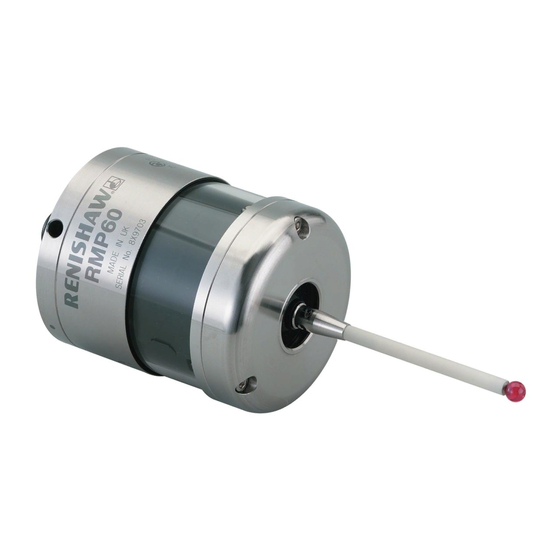
RMP60 — radio probe
Related Manuals for Renishaw RMP60
Summary of Contents for Renishaw RMP60
-
Page 1
Installation and user’s guide H-2000-5219-01-A RMP60 — radio probe… -
Page 2
The publication of material within this document does not imply freedom Trademarks from the patent rights of Renishaw plc. All brand names and product names used in this document are trade names, service marks, trademarks, or registered trademarks of their respective owners. -
Page 3
Emissions to class A (non-domestic) limits. and that it complies with the requirements of directive (as amended): — 89/336/EEC — Electromagnetic compatibility The above information is summarised from the full EC declaration of conformity. A copy is available from Renishaw on request. -
Page 4
Keep system components clean and treat the must be returned to your supplier. No claims probe as a precision tool. will be considered where Renishaw equipment Patent notice has been misused, or repairs or adjustments have been attempted by unauthorised persons. -
Page 5: Table Of Contents
Contents Contents Typical probe system with radio RMP60 batteries ……….. 17 transmission ………… 4 Battery life expectancy ……… 19 System performance ……..5 RMP60/shank mounting ……. 21 Operating envelope ……… 6 Stylus on-centre adjustment ……22 RMP60 features ……….7 Stylus trigger force adjustment …..
-
Page 6: Typical Probe System With Radio Transmission
Typical probe system with radio transmission Typical probe system with radio transmission CNC machining centre spindle Interface mounting bracket RMP60 C N C inspection probe machine control Optional — PSU3 power supply unit Probe status LEDs Typical tool setting probe…
-
Page 7: System Performance
RMP60 signal transmission range. Temperature PSU3 Coolant and swarf residue accumulating on the RMP60 and RMI may have a detrimental effect -10 °C to 70 °C Storage on transmission performance. Wipe clean as (14 °F to 158 °F) often as is necessary to maintain unrestricted 5 °C to 50 °C…
-
Page 8: Operating Envelope
Operating envelope Operating envelope Range metres (feet) RMP60 probe + RMI OPERATING AND SWITCH ON/OFF RMP60 and RMI must be within each others 75° 15 (49) operating envelope shown. 60° 90° 75° 75° 10 (33) 60° 60° 45° 45° 45°…
-
Page 9: Rmp60 Features
RMP60 features RMP60 features Dimensions mm (in) 50 (1.97) 19 (0.75) A range of probe ready shanks is available from RMP60 window Renishaw upon request M4 stylus 18° 18° Battery cover Ø63 (Ø2.48) 76 (2.99) STYLUS OVERTRAVEL LIMITS Stylus length ±X / ±Y…
-
Page 10: Rmp60 Specification
Z direction 4.90 N / 490 gf green operating mode (17.28 ozf) and blue — low battery Flashing Probe triggered in RMP60 IP rating IPX8 red and operating mode blue — low battery RMP60 weight Without batteries (without shank) 855 g (30.16 oz)
-
Page 11: Probe Status Led
X / Y Weak link (steel styli only) 18° 18° Fitting stylus with weak Removing a broken Fitting a weak link link onto RMP60 weak link In the event of 2 Nm (1.7 lbf.ft) excessive stylus 5 mm AF overtravel the weak 2 Nm (1.7 lbf.ft)
-
Page 12: Modes Of Operation
Modes of operation Modes of operation RMP60 switch-on RMP60 power on/off The RMP60 probe can be in one of three modes: Switch-on options are configurable 1. Stand-by mode — The RMP60 is waiting for — see page 13. a switch-on signal .
-
Page 13
2. Timer off (time out) Note: (Only applies when radio on/spin on After being turned on, the RMP60 must be mode is selected). on for a minimum of 1 sec (7 sec for spin The RMP60 will time out (12, 33 or off) before being turned off. -
Page 14: Reviewing Current Probe Settings
Reviewing current probe settings Reviewing current probe settings START Note This menu will be omitted if shank Batteries removed from probe turn on has been selected Insert batteries: note the LED sequence, which follows the form below SWITCH OFF METHOD setting Short Medium Long…
-
Page 15: Configuration Using Trigger Logic
Configuration using trigger logic Configuration using trigger logic START Note This menu will be omitted if shank Remove batteries from probe. turn on has been selected Hold stylus deflected and insert batteries. Release the stylus only after 15 seconds. SWITCH OFF METHOD menu The current probe settings review Deflect the stylus (>0.5 sec) to sequence, detailed on page 12 will…
-
Page 16
Settings record table ACQUISITION MODE ACQUISITION MODE Switch on Radio method Shank Once configuration is complete, leave the RMP60 in triggered for 20 sec to save Spin configuration and go to stand-by. Radio/spin Switch off method Return to Short time out… -
Page 17: System Setup/Establishing Rmp60/Rmi Partnership
6. RMI pattern will change to red & yellow configuration using trigger logic. flashing when it acquires the RMP. 1. Use trigger logic to set RMP60 turn on/ off 7. Allow ~10 seconds for both RMP60 and modes as desired.
-
Page 18
RMI to be partners with more than one RMP60. It is possible for an RMP60 to be partners with more than one RMI, but the system will not work correctly if more than one partner RMI is… -
Page 19: Rmp60 Batteries
Only use specified batteries. Do not mix new and used batteries or battery types, as this will result in reduced life and Clean and dry RMP60 with a cloth or paper towel damage to the batteries. before removing battery cover. Where the…
-
Page 20
RMP60 batteries Battery cover Batteries 2 x AA DO NOT leave exhausted batteries in probe Please dispose of exhausted batteries DO NOT allow coolant or debris to enter the in accordance with local regulations. battery compartment Do not dispose of batteries in fire. -
Page 21: Battery Life Expectancy
(page 12). typically the probe will continue to operate for In order to achieve stated radio stand-by life, approximately 2 weeks after a low battery the RMP60 must be in range of powered warning is first indicated. partner RMI. CONTINUOUS…
-
Page 22
Part number will change to constant red. 596-602, 201-9438, Radio Shack 23-037 Battery specification The RMP60 requires two identical AA size Manufacturer Part number batteries, individually rated at a voltage of Saft LS 14500 between 1.2 V and 3.6 V. -
Page 23: Rmp60/Shank Mounting
6. Tighten screws B to 6-8 Nm (4.4- 5.9 lb.ft) (Partially tighten screws B to 2 — 3 Nm (1.47 — 2.2 lbf.ft), if RMP60 is to be on-centre adjusted). 7. The RMP60 assembly is ready for use.
-
Page 24: Stylus On-Centre Adjustment
20 µm, fully tighten screws B to 6 — 8 Nm (4.4 — 5.9 lbf.ft). 10. For final centering use screws A to move the RMP60, progressively slackening on one side and tightening the opposite screw, as the final setting is approached, using two hexagon keys.
-
Page 25: Stylus Trigger Force Adjustment
Spring force within the probe causes the stylus to sit in one unique position, and return to this position following each stylus deflection. Stylus trigger force is set by Renishaw. The user should only adjust trigger force in special circumstances e.g. excessive machine vibration or insufficient force to support the stylus weight.
-
Page 26: Probe Moves
Probe moves Probe moves Probe trigger With a double touch sequence the first move finds the surface quickly. Then the probe is backed off A probe trigger signal is generated when the to a position clear of the surface, before making probe’s stylus is driven against a surface.
-
Page 27
Probe interface signals 1. Error signal delay Probing cycles are available from Renishaw A delay of 28 ms maximum for the RMI, will elapse between an error occurring and the Calibrating a system output indicating error. -
Page 28: Software Requirements
Software requirements Software requirements Verify your software Probing cycles and features are machine Does your software have suitable calibration software dependant. Good software will allow the routines which compensate for stylus on-centre following functions : errors? If not, you must set the probe stylus on-centre mechanically.
-
Page 29: Typical Probe Cycles
Typical probe cycles for machining centres Typical probe cycles for machining centres Simple to use canned cycles for basic features Inspection probe Inspection calibration Bore and boss measure Probe XY offset calibration Web and pocket measure Stylus ball radius calibration Internal and external corner find Probe length calibration…
-
Page 30
Bore and boss on PCD 4th axis measure Angled web and pocket measure Feature-to-feature measure Angled surface measure Macro software for use with the RMP60 is available from Renishaw for the majority of major controller types, please see Parts list (page 39). -
Page 31: Diaphragm Replacement
Diaphragm replacement Diaphragm replacement RMP60 DIAPHRAGMS OUTER DIAPHRAGM INSPECTION The probe mechanism is protected 1. Remove the stylus. from coolant and debris by two diaphragms. 2. Undo three M3 front cover screws These provide adequate protection under and remove the front cover normal working conditions.
-
Page 32
Diaphragm replacement OUTER DIAPHRAGM REPLACEMENT 6. Fit new diaphragm over centre. M3 screw 7. Locate outer edge of diaphragm to rest 2.5 mm AF on outer edge of inner diaphragm. 1 Nm (0.74 lbf.ft) 8. Refit front cover and M3 screws. 9. -
Page 33: Fault Finding
Fault-finding Fault finding — If in doubt, consult your probe supplier. Symptom Cause Action RMP60 fails to switch on Dead batteries Change batteries Batteries incorrectly Check/change batteries inserted Probe out of range Check position of RMI, see (does not apply to spin-on performance envelope.
-
Page 34
Fault-finding Symptom Cause Action RMP60 fails to switch off Incorrect switch off method Check configuration and alter configured. as required. No RMI ‘start/stop’ signal Check for green start LED (applicable only in radio off, Check wiring. mode, but not applicable in Heidenhain mode). -
Page 35
Review program. path. No LED’s lit on RMI No power to RMI Check wiring RMI status LED’s do not Radio link failure – RMP60 Check position of RMI, correspond to RMP60 out of RMI range. see performance envelope. status LED’s… -
Page 36
Fault-finding Symptom Cause Action RMI error LED lit during Probe timed out Change setting. probing cycle (continued) Review turn off method Probe out of range Check position of RMI, see performance envelope. RMI error LED illuminated Probe not switched on. Check configuration and alter during intended probe cycle as required… -
Page 37
Fault-finding Symptom Cause Action Poor measurement Debris on part or stylus. Clean. results. Recalibrate if probe was calibrated with debris on stylus. Repeatability of probe Verify by repeated toolchange into spindle. and single point move. Loose probe to shank Check and tighten as mounting or stylus. -
Page 38: Appendix 1 Rmi
Appendix 1 Appendix 1 RMI (RADIO MACHINE INTERFACE) The RMI is fully described in User’s guide H-2000-5220 A visual indication of system status is provided by light emitting diodes (LED’s). Status is continuously updated and indication is provided for START, LOW BATTERY, PROBE STATUS, ERROR, SIGNAL STRENGTH LED LIGHT SIGNALS 1.
-
Page 39
Appendix 1 3. Error Notes. Error, other outputs may 1. The probe status LED will always be be incorrect. illuminated when power is present, there is no power present LED/light. Off: No Error. 2. All the indicators report the status of the 4. -
Page 40: Parts List
Please quote the Part no. when ordering equipment. Type Part no. Description RMP60 A-4113-0001 RMP60 probe with batteries, tool kit and User’s guide (set to radio on/radio off). RMP60 A-4113-0002 RMP60 probe with batteries, tool kit and User’s guide (set to radio on/time off).
-
Page 41
— For complete listing please see Renishaw Styli guide. Part no. H-1000-3200. Software — For complete list of Renishaw software for machine tools please see Data sheet. Part no. H-2000-2289. Shanks — For complete listing please see Renishaw Data sheet… -
Page 42
Renishaw plc +44 (0)1453 524524 New Mills, Wotton-under-Edge, +44 (0)1453 524901 Gloucestershire, GL12 8JR uk@renishaw.com United Kingdom www.renishaw.com For worldwide contact details, please visit our main website at www.renishaw.com/contact *H-2000-5219-01-A*…
PL
Publikacje dla tego produktu są również dostępne w formie elektronicznej na minidysku CD w
kieszeni wewnątrz przewodnika. Aby je przeglądać, należy włożyć dysk do napędu CD komputera
PC, wybrać pożądany język, a następnie wybrać publikację. Pliki mogą być też wydrukowane w
razie potrzeby. Aby uzyskać więcej informacji, odwiedź witrynę
www.renishaw.pl/rmp60.
CS
Publikace pro tento výrobek jsou k dispozici v elektronickém formátu na mini disku CD‑ROM,
který naleznete v kapse na zadním přebalu originálního šestijazyčného návodu. Chcete‑li si je
prohlédnout, vložte disk CD do jednotky CD vašeho počítače, zvolte jazyk, a nakonec si vyberte
publikaci. Soubory lze v případě potřeby také vytisknout. Více informací najdete na adrese
www.renishaw.cz/rmp60.
RU
В кармане на задней стороне обложки прилагается мини-CD, содержащий публикации
по данному изделию в электронном формате. Для просмотра этих материалов следует
вставить CD в дисковод своего компьютера, выбрать язык, а затем выбрать нужный
документ. При необходимости файлы могут быть распечатаны. Более подробная
информация приведена на сайте www.renishaw.ru/rmp60.
中文
(繁體)
本指南封底內頁紙袋中備有一袖珍型光碟,內有本產品說明書之電子文檔與軟體,若欲瀏覽,請將
光碟插入電腦光碟機中,選取所需語言,再選擇欲瀏覽項目即可。如有需要亦可列印檔案。若需更
多詳細資料,請造訪網站 www.renishaw.com./rmp60。
中文
(简体)
本手册也供有电子文档,请见封三所附的光盘。要查看这些文档,请将光盘插入电脑的光驱中,选
择所要的语言,然后选择一个文档。如果需要也可打印该文档。如需更多信息,请浏览
www.renishawchina.com/rmp60。
한국어
이 제품 관련 문서는 안내서 뒷 표지 안쪽에 있는 CD에 전자 문서 형식으로 포함되어
있습니다. 이 문서를 보려면 PC의 CD 드라이브에 CD를 넣고 언어를 선택한 후 원하는 문서를
선택하십시오. 필요하면 파일을 인쇄할 수 있습니다. 자세한 내용은 www.renishaw.co.kr/rmp60
을 참조하십시오.
CAUTION: The RMP60 has a glass
window. Handle with care if broken to
avoid injury.
ACHTUNG: Der RMP60 besitzt ein
Glasfenster. Gehen Sie im Fall eines
Bruchs vorsichtig damit um, um eine
Verletzung zu vermeiden.
PRECAUCIÓN: La sonda RMP60 tiene
una ventana de cristal. Si se rompe,
manéjela con cuidado para evitar
lesiones.
ATTENTION : L’RMP60 a une fenêtre en
verre. Manipuler avec précaution en cas
de rupture pour éviter les blessures.
ATTENZIONE: RMP60 dispone di una
finestra di vetro. In caso di rottura della
finestra, fare attenzione per evitare
lesioni personali.
RMP60
UWAGA: Sonda RMP60 posiada
szklane okienko. W razie rozbicia
operować z zachowaniem
ostrożności, aby uniknąć obrażeń.
VAROVÁNÍ: RMP60 má skleněné
okénko. Pokud je rozbité, zacházejte
s ním opatrně, abyste zabránili
poranění.
ВНИМАНИЕ! Прибор RMP60
оснащен стеклянным окошком.
Если стекло разбито, обращаться
с осторожностью во избежание
травмы.
注意:RMP60 配有一個玻璃視窗,
請小心處理,萬一有破裂時,應謹慎
避免割傷。
小心:RMP60有一个玻璃窗口。如
果玻璃破裂,请小心处理以避免造
成伤害。
경고: RMP60에는 유리창이 있습니
다. 유리가 파손되어 부상을 입지 않
도록 주의하십시오.
EN
DE
ES
FR
IT
PL
CS
RU
中文
(繁體)
中文
(简体)
한국어
! !
Radio approval (continued)
Brazil: Taiwan:
RMP60: CCAC07LP0100T2
RMP60M: CCAC07LP0101T1
PL
CS
RU
中文
(
繁體)
中文
(简体)
한국어
In the countries identified below an additional label is required. The label must be fitted on the side of
the RMP60 battery housing, but not across the glass window:
In den unten aufgeführten Ländern muss ein zusätzlicher Aufkleber angebracht werden. Der Aufkleber
muss seitlich des RMP60 Batteriefaches angebracht werden. Nicht über die Glasfläche kleben.
En los paises señalados mas abajo es necesario una etiqueta adicional. La etiqueta debe ser
colocada al lado de la ubicación de las baterías, pero no sobre la ventana de cristal.
Dans les pays indentifiés ci-après, une étiquette supplémentaire est exigée. L’étiquette doit être
aposée sur le côté du logement de piles du RMP60 mais pas en travers de le fenêtre en verre :
Nei paesi sotto indicati è necessaria una etichetta aggiuntiva. Tale etichetta deve essere applicata sulla
sonda lateralmente, a fianco del vano batterie, non sulla finestra in vetro.
下記の国で使用される場合、追加ラベルの貼付が必要です。ラベルはRMP60のバッテリーハウジング
部分に貼り付けてください。ガラス部分には貼り付けないでください。
W krajach wymienionych poniżej konieczna jest dodatkowa nalepka informacyjna. Musi być ona
umieszczona na bocznej obudowie RMP60 ale nie na szklanym okienku.
V zemích uvedených níže je požadována přidaná značka. Tato značka musí být umístěna na straně
držáku baterií sondy RMP60, ne však přes skleněný průzor.
В нижеперечисленных странах необходимо использование дополнитнльной маркировки.
Маркировка должна наноситься на отсек для батареек, но не должна закрывать стеклянное окошко.
在下列國家要求下,產品必須要加上一個識別標籤。標籤必須安置於RMP60電池蓋外側,但不可以遮
蔽玻璃視窗。
下列国家/地区要求另贴一张标签。标签必须贴在RMP60电池座的旁边,但不能遮挡玻璃窗。
아래에 명기된 국가에서는 별도의 라벨이 필요합니다. 이 라벨은 RMP60 밧데리 하우징에 부착 되어
야 하며, 유리창을 막게 부착해서는 않됩니다:
EN
DE
ES
FR
IT
日本語
2-5
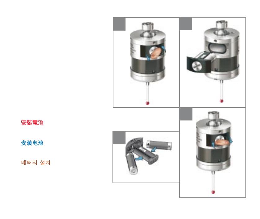
Instalowanie baterii
V Należy uważać, aby nie doszło do
zwarcia styków, ponieważ stanowi to
zagrożenie pożarowe. Konieczne jest
także, by zadbać o właściwe rozłożenie
taśm stykowych.
Instalace baterií
V Dávejte pozor, abyste nezkratovali
kontakty baterie, může to vést k riziku
požáru. Zkontrolujte, že jsou kontaktní
pásky v bezpečné poloze.
Установка батарей
V Не допускайте замыкания
контактов батареек во избежание
возгорания. Следите за надежным
закреплением контактных вставок.
安裝電池
V 注意請勿使電池接點短路,因為這可
能引起火災。 確定接點簧片放置牢靠。
安装电池
V 注意请勿使电池短路,因为这可能引
起火灾。确定接触片放置牢靠。
배터리 설치
V 화재 위험이 있으므로 배터리 접촉부
가 단락되지 않도록 주의해야 합니다.접
촉부 스트립이 안전하게 고정되어 있는
지 확인하십시오.
1
2
4
3
V
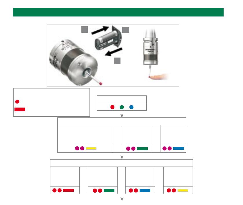
2-22
X
Условные обозначения
Быстрое мигание индикатора
Медленное мигание индикатора
Проверка настроек датчика
Проверка индикатора
Для изменения метода включения
По радиосигналу
(исключается, если выбран
режим использования нескольких
измерительных систем)
или
От выключателя
на хвостовике
или
Вращением
Метод выключения (исключая выключатель на хвостовике)
Выключение по
радиосигналу
или вращением
или
Короткий
период
ожидания
12 сек.
или
Средний период
ожидания
33 сек.
или
Длинный
период
ожидания
134 сек.
> 5 s
1
2
3
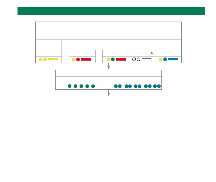
2-23
Проверка настроек датчика
Заряд батареек
Батареи в норме
или
Батарейки разряжены
Датчик в режиме ожидания (после 5 сек.)
Режим использования нескольких измерительных систем (исключается при включении по
радиосигналу)
(см. описание всех 16 опций в разделе «Настройки режима использования нескольких
измерительных систем»)
Режим
выключен
Режим включен
или
Станок 1
или
Станок 2 Станок 16
2-24
Настройки режима использования нескольких измерительных систем
Режим
выключен
Режим включен
Станок 1 Станок 2 Станок 3 Станок 4
Станок 5 Станок 6 Станок 7 Станок 8
Станок 9 Станок 10 Станок 11 Станок 12
Станок 13 Станок 14 Станок 15 Станок 16
Отклоните
щуп на время
менее 4
секунд для
перехода к
следующей
опции меню
Возврат к выключенному режиму
Настройки режима использования нескольких измерительных систем
2-25
3
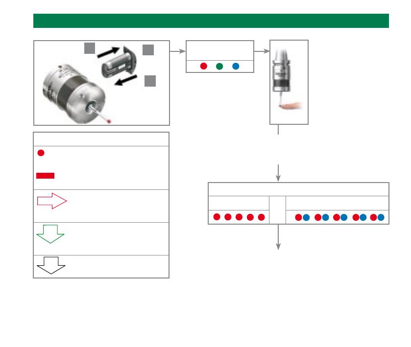
Перевод датчика в режим настройки
Проверка
индикатора
Сместив щуп, удерживайте его в
смещенном положении вплоть до
появления значения заряда батареек.
Условные обозначения
Быстрое мигание
индикатора
Медленное мигание
индикатора
Смещение щупа < 4 сек.
Для перехода к следующему
пункту меню.
Смещение щупа > 4 сек.
Для перехода к следующему
меню.
Для выхода оставьте щуп в
покое > 20 сек.
Заряд батареек
Батареи в норме
или
Батарейки разряжены
> 5 s
1
2
3
Порядок смены режима включения
см. на следующей странице
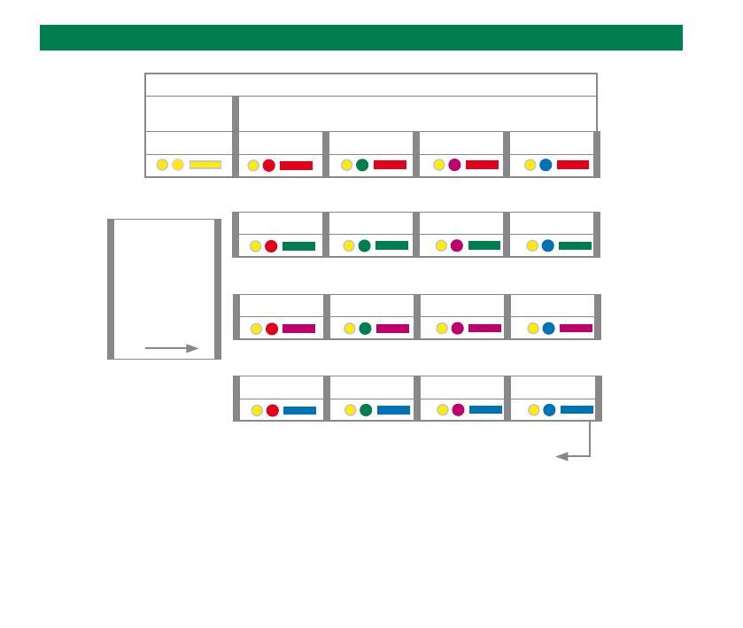
2-26
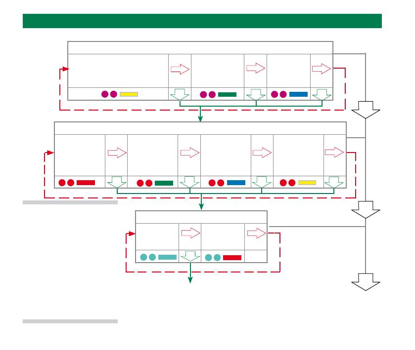
Смена настроек датчика
Порядок смены режима включения
По радиосигналу
(исключается, если выбран
режим использования нескольких
измерительных систем)
От выключателя
на хвостовике
Вращением
Порядок смены режима выключения (исключая выключатель на хвостовике)
Выключение
по
радиосигналу
или
вращением
Короткий
период
ожидания
12 сек.
Средний период
ожидания
33 сек.
Длинный
период
ожидания
134 сек.
Настройка
завершена
Режим обнаружения
Режим
oбнаружения
выключен
Режим
обнаружения
включен
Прервать срабатывание на этом этапе, если не
требуется режим использования нескольких
измерительных систем (в этом случае
отклоните щуп на время более 4 секунд)
Примечание: после
успешного завершения
операции обнаружения
датчик RMP60 переходит
в состояние «Режим
обнаружения выключен».
Согласование устройств
RMP60-RMI.
2-27
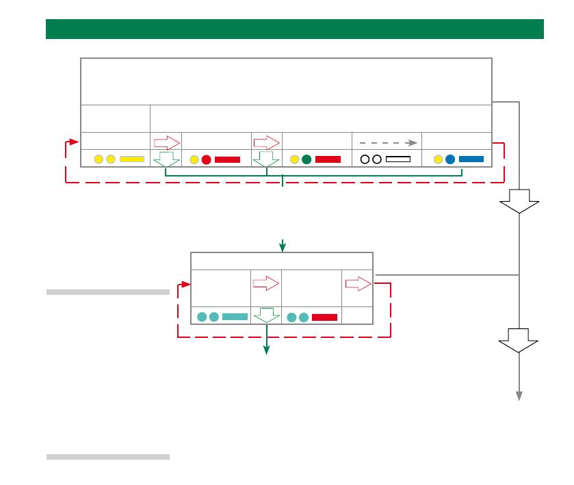
Настройка
завершена
Смена настроек датчика (Продолжение следует)
Режим использования нескольких измерительных систем (исключается при включении по
радиосигналу)
(см. описание всех 16 опций в разделе «Настройки режима использования нескольких измерительных
систем»)
Режим
выключен
Режим включен
Станок 1 Станок 2 Станок 16
Режим обнаружения
Режим
oбнаружения
выключен
Режим
обнаружения
включен
Возврат к пункту
«Для изменения метода включения»
Примечание: если в режиме использования нескольких измерительных
систем не было сделано никаких изменений, то отклонение щупа более чем
на 4 секунды приводит к возврату настроек датчика в состояние «Изменение
метода включения».
Примечание: после
успешного завершения
операции обнаружения
датчик RMP60 переходит
в состояние «Режим
обнаружения выключен».
Согласование устройств
RMP60-RMI.
2-28
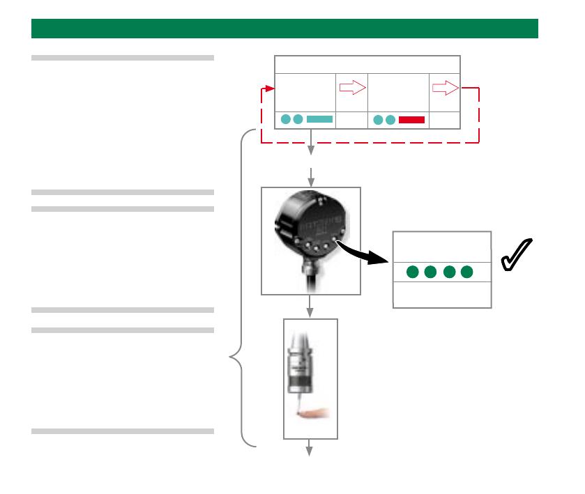
Согласование устройств RMP60-RMI
Режим обнаружения
Режим
oбнаружения
выключен
Режим
обнаружения
включен
продолжение на следующей странице
ИНДИКАТОР SIGNAL
(СИГНАЛ)
RMI находится в
режиме обнаружения
3
Примечание: задайте нужные
параметры в режиме настройки, а
затем перейдите в меню «Режим
обнаружения». Выберите опцию
«Режим обнаружения выключен».
Примечание: если датчик
RMP60 не находится в режиме
использования нескольких
измерительных систем, то
необходимо перед началом
работы выполнить его
согласование с устройством RMI.
3
Отклоните щуп для перехода
в режим обнаружения. Эта
операция должна быть
выполнена в течение 10 секунд,
пока мигает зеленым цветом
индикатор сигнала RMI.
Примечание: Следующие два
шага должны быть осуществлены
в течение 20 секунд после
перехода в режим обнаружения
выключен.
Включить RMI
< 4 s

3-v
© 2008 Renishaw plc。 保留所有權利。
本文檔未經RENISHAW公司事先書面許可,不得以任何形式,進行
部分或全部複製或轉換為任何其他媒介或語言。
出版本文檔所含材料並不暗示Renishaw公司放棄對其所擁有的專
利權。
免責條款
RENISHAW已竭力確保在發佈日期之時,本文件的內容準確無
誤,然而RENISHAW對其內容不作任何擔保,其內容亦不代表
RENISHAW的立場。RENISHAW不承擔因本文件內容任何的不準
確之處無論以任何方式所起的問題的相關責任。
商標
RENISHAW公司徽標中的RENISHAW®及測頭象徵符號是
Renishaw 公司在香港及其他國家或地區的
注冊商標。
apply innovation和Trigger Logic是Renishaw公司的商標。
Adobe和Acrobat是Adobe Systems公司在美國及/或其他國家或地
區的註冊商標或商標。
本文檔中使用的所有其他品牌名稱和產品名稱為各自所有者的商品
名稱、服務標誌、商標或註冊商標。
© 2008 Renishaw plc. Все права защищены.
Настоящий документ не подлежит копированию или
воспроизведению целиком или частично, переводу на
другие носители или языки при помощи любых средств
без предварительного письменного разрешения компании
Renishaw.
Публикация материалов в рамках настоящего документа не
освобождает от соблюдения патентных прав компании
Renishaw plc.
Отказ от ответственности
КОМПАНИЯ RENISHAW ПРИЛОЖИЛА ЗНАЧИТЕЛЬНЫЕ
УСИЛИЯ ДЛЯ ОБЕСПЕЧЕНИЯ ДОСТОВЕРНОСТИ
ИНФОРМАЦИИ, СОДЕРЖАЩЕЙСЯ В НАСТОЯЩЕМ
ДОКУМЕНТЕ, НА ДАТУ ЕГО ПУБЛИКАЦИИ. ОДНАКО
КОМПАНИЯ НЕ ПРЕДОСТАВЛЯЕТ НИКАКИХ ГАРАНТИЙ
ИЛИ ЗАЯВЛЕНИЙ В ОТНОШЕНИИ СОДЕРЖИМОГО
НАСТОЯЩЕГО ДОКУМЕНТА. КОМПАНИЯ RENISHAW
ИСКЛЮЧАЕТ ОТВЕТСТВЕННОСТЬ, ТЕМ ИЛИ ИНЫМ
ОБРАЗОМ ВОЗНИКАЮЩУЮ ВСЛЕДСТВИЕ НЕТОЧНОСТЕЙ В
НАСТОЯЩЕМ ДОКУМЕНТЕ.
Торговые марки
являются зарегистрированными торговыми марками компании
Renishaw plс в Великобритании и других странах.
apply innovation и Trigger Logic являются торговыми марками
компании Renishaw plc.
Adobe и Acrobat являются зарегистрированными торговыми
марками или торговыми марками компании Adobe Systems
Incorporated в США и/или других странах.
Все остальные торговые марки и названия
изделий,встречающиеся в содержании настоящего документа,
являютсяторговыми наименованиями, знаками обслуживания,
торговымимарками или зарегистрированными торговыми
марками ихсоответствующих владельцев.
RU
中文 (繁體)
![]()
Installation and user’s guide
H-2000-5219-01-A
RMP60 — radio probe
© 2003 Renishaw. All rights reserved.
Renishaw® is a registered trademark of Renishaw plc.
This document may not be copied or reproduced in whole or in part, or transferred to any other media or
language, by any means, without the prior written permission of Renishaw.
The publication of material within this document does not imply freedom from the patent rights of Renishaw plc.
Renishaw Part no: H-2000-5219-01-A
Issued: 08.2003
Disclaimer
Considerable effort has been made to ensure that the contents of this document are free from inaccuracies and omissions. However, Renishaw makes no warranties with respect to the contents of this document and specifically disclaims any implied warranties. Renishaw reserves the right to make changes to this document and to the product described herein without obligation to notify any person of such changes.
Trademarks
All brand names and product names used in this document are trade names, service marks, trademarks, or registered trademarks of their respective owners.

1
EC DECLARATION OF CONFORMITY
Renishaw plc declare that the product: —
Name: RMP60
Description: Radio machine probe
has been manufactured in conformity with the following standard: —
BS EN 61326:1998/ Electrical equipment for measurement, control and laboratory use — EMC requirements.
Immunity to annex A — industrial locations. Emissions to class A (non-domestic) limits.
and that it complies with the requirements of directive (as amended): —
|
89/336/EEC |
— Electromagnetic compatibility |
The above information is summarised from the full EC declaration of conformity. A copy is available from Renishaw on request.
|
2 |
Installation and user’s guide |
Installation and user’s guide
Warranty
Equipment requiring attention under warranty must be returned to your supplier. No claims will be considered where Renishaw equipment has been misused, or repairs or adjustments have been attempted by unauthorised persons.
Changes to equipment
Renishaw reserves the right to change specifications without notice.
CNC machine
CNC machine tools must always be operated by competent persons in accordance with manufacturers instructions.
Care of the probe
Keep system components clean and treat the probe as a precision tool.
Patent notice
Features of products shown in this guide, and of related products, are the subject of the following patents and/or patent applications:
EP 0652413
US 4599524
US 5,279,042
JP 3,126,797
WO 02/063235
WO 03/021182

Contents 3
|
Contents |
|
|
Typical probe system with radio |
|
|
transmission ……………………………………………. |
4 |
|
System performance ……………………………….. |
5 |
|
Operating envelope ………………………………….. |
6 |
|
RMP60 features ………………………………………. |
7 |
|
RMP60 specification ………………………………… |
8 |
|
Probe status LED …………………………………….. |
9 |
|
Weak link stem ………………………………………… |
9 |
|
Modes of operation ………………………………… |
10 |
|
Reviewing current probe settings ……………. |
12 |
|
Configuration using trigger logic ………………. |
13 |
|
System setup/establishing |
|
|
RMP60/RMI partnership …………………………. |
15 |
|
RMP60 batteries ……………………………………. |
17 |
|
Battery life expectancy …………………………… |
19 |
|
RMP60/shank mounting …………………………. |
21 |
|
Stylus on-centre adjustment ……………………. |
22 |
|
Stylus trigger force adjustment ………………… |
23 |
|
Probe moves …………………………………………. |
24 |
|
Software requirements ……………………………. |
26 |
|
Typical probe cycles ………………………………. |
27 |
|
Diaphragm replacement ………………………….. |
29 |
|
Fault finding ……………………………………………. |
31 |
|
Appendix 1 RMI ……………………………………. |
36 |
|
Parts list ………………………………………………… |
38 |
|
4 |
Typical probe system with radio transmission |
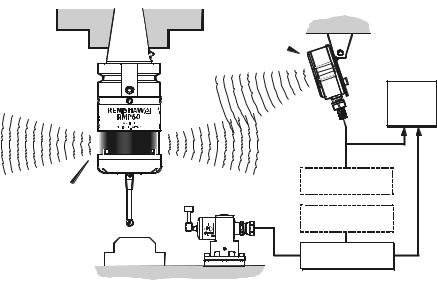
Typical probe system with radio transmission
CNC machining centre spindle
RMI
Interface
RMP60 inspectionprobe
|
Probe status LEDs |
Typical tool setting probe |
Stylus
Cable
RMI mounting bracket
C N C machine control
Optional — PSU3 power supply unit
Optional — PSU3 power supply unit
A workpiece set-up and inspection probe is in effect another tool in the system.
A probing cycle may be included at any stage of the machining process.
Probe data signals are transmitted via radio link to the RMI and on to the machine control. The RMI converts probe signals into an acceptable form for the machine control.
System performance
Operating envelope
Surfaces within the machine may increase the signal transmission range.
Coolant and swarf residue accumulating on the RMP60 and RMI may have a detrimental effect on transmission performance. Wipe clean as often as is necessary to maintain unrestricted transmission.
When operating, do not touch with your hand, either the RMI cover or the probe glass window, as this will change the performance.
Operation in extremes of temperature will result in some reduction in range.
RMI position
To assist finding the optimum position of the RMI during system installation, a signal strength indication LED is available on the RMI interface.
RMI signal strength is displayed on an RMI multi-coloured LED.
Environment
|
RMP60 |
Temperature |
|
|
RMI |
||
|
PSU3 |
||
|
Storage |
-10 °C to 70 °C |
|
|
(14 °F to 158 °F) |
||
|
Normal |
5 °C to 50 °C |
|
|
operating |
(41 F° to 122 °F) |
|
Probe repeatability
Maximum 2 Sigma (28) Value
Repeatability of 1,0 µm (40 µ in) is valid for test velocity of 480 mm/min (1.57 ft/min) at stylus tip, using stylus 50 mm (1.97 in) long.

6 Operating envelope
Operating envelope
|
RMP60 probe + RMI |
Range metres (feet) |
||||||||
|
OPERATING AND SWITCH ON/OFF |
|||||||||
|
RMP60 and RMI must be within each others |
|||||||||
|
operating envelope shown. |
75° |
15 (49) |
|||||||
|
75° |
90° |
75° |
60° |
||||||
|
10 (33) |
|||||||||
|
60° |
60° |
||||||||
|
45° |
45° |
||||||||
|
45° |
5 (16) |
||||||||
|
30° |
30° |
||||||||
|
15° |
15° |
||||||||
|
0° |
0° |
5 |
|||||||
|
(16) |
|||||||||
|
15° |
5 |
15° |
15° |
10 |
|||||
|
(1 6) |
|||||||||
|
(33) |
|||||||||
|
10 10 |
30° |
||||||||
|
30° |
(33) |
(33) |
|||||||
|
30° |
15 |
||||||||
|
15 |
15 |
45° |
|||||||
|
(49) |
|||||||||
|
45° |
45° |
60° |
|||||||
|
(49) |
(49) |
75° |
|||||||
|
60° |
60° |
||||||||
|
75° |
90° |
75° |
|||||||
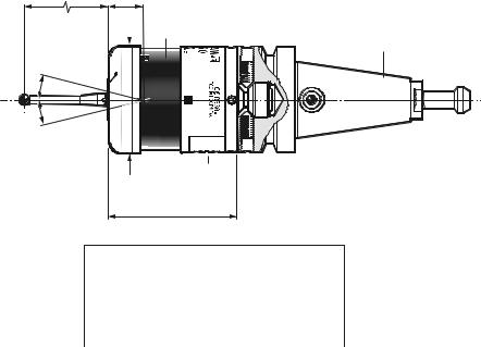
RMP60 features
RMP60 window
Battery cover
Ø63 (Ø2.48)
76 (2.99)
STYLUS OVERTRAVEL LIMITS
Dimensions mm (in)
A range of probe ready shanks is available from Renishaw upon request
|
Stylus length |
±X / ±Y |
Z |
|
|
50 (1.96) |
21 |
(0.82) |
11 (0.43) |
|
100 (3.93) |
37 |
(1.45) |
11 (0.43) |

RMP60 specification
Stylus trigger force
X/Y trigger forces vary, depending on trigger direction. There are 3 high force and 3 low force directions
|
X/Y direction |
Typical lowest force |
|
(50 mm stylus) |
0.75 N / 75 gf |
|
(2.64 ozf) |
|
|
Typical highest force |
|
|
1,4 N / 140 gf (4.92 ozf) |
|
|
Z direction |
4.90 N / 490 gf |
|
(17.28 ozf) |
|
|
RMP60 IP rating |
IPX8 |
|
RMP60 weight |
Without batteries |
|
(without shank) |
855 g (30.16 oz) |
|
With batteries |
|
|
901 g (31.79 oz) |
PROBE STATUS LED
|
LED |
Probe status |
Graphic hint |
|
|
colour |
|||
|
Unlit |
Stand-by mode |
||
|
Flashing |
Probe seated in |
||
|
green |
operating mode |
||
|
Flashing |
Probe triggered in |
||
|
red |
operating mode |
||
|
Flashing |
Probe seated in |
||
|
green |
operating mode |
||
|
and blue |
— low battery |
Flashing Probe triggered in red and operating mode blue — low battery
Constant
Battery dead
red
Max spin speed 1000 rev/min
![]()
Probe status LED
|
LEDs |
19 mm |
LEDs |
|
|
flashing |
flashing |
||
|
GREEN |
RED |
||
|
X / Y |
|||
|
Weak link (steel styli only) |
18° 18° |
||
|
Fitting stylus with weak |
|||
|
link onto RMP60 |
Fitting a weak link |
In the event of
2 Nm (1.7 lbf.ft)
excessive stylus
overtravel the weak link is designed
to break, thereby protecting the probe from damage.
Take care to avoid stressing the weak link during assembly.
5 mm AF
2 Nm (1.7 lbf.ft)
12 mm
(0.47 in)
Z
11 mm
Removing a broken weak link

10 Modes of operation
Modes of operation
The RMP60 probe can be in one of three modes:
1.Stand-by mode — The RMP60 is waiting for a switch-on signal .
2.Operating mode — Activated by one of the switch on methods described on this page. In this mode and the RMP60 is now ready for use.
3.Configuration mode — The trigger-logic configuration method allows a number of RMP60 set-up options to be configured by triggering the RMP60, including the switch-off options described on page 25.
RMP60 switch-on
RMP60 power on/off
Switch-on options are configurable
— see page 13.
Three switching methods can be used.
1.Radio start
Radio switch-on is commanded by
M code.
2.Spin start
Spin at 650 rev/min for 1 sec minimum (maximum 6 sec)
3.Shank switch
Note:
RMP60 will be turned on after 1 sec in all modes.
|
Modes of operation |
11 |
|||||
|
RMP60 switch-off |
||||||
|
Switch-off options are programmable |
3. |
Spin stop |
||||
|
Three switching methods can be used. |
(Only applies when spin on mode is |
|||||
|
1. Radio stop |
selected). |
|||||
|
Radio switch off is commanded by a |
A timer switch automatically swiches |
|||||
|
the probe off after 90 min from last |
||||||
|
M code. |
||||||
|
trigger off, if not spun off. |
||||||
|
(Only applies when radio turn on is |
||||||
|
selected). |
4. |
Shank switch |
||||
|
A timer automatically switches the probe off |
(Only applies when shank on mode is |
|||||
|
after 90 min from last trigger if not turned off |
selected). |
|||||
|
by M-code. |
||||||
|
2. Timer off (time out) |
||||||
|
Note: |
||||||
|
(Only applies when radio on/spin on |
||||||
|
After being turned on, the RMP60 must be |
||||||
|
mode is selected). |
||||||
|
on for a minimum of 1 sec (7 sec for spin |
||||||
|
The RMP60 will time out (12, 33 or |
||||||
|
off) before being turned off. |
||||||
|
134 sec) after the last probe trigger or |
||||||
|
reseat. |
||||||
 Loading…
(Ocr-Read Summary of Contents of some pages of the Renishaw RMP60 Document (Main Content), UPD: 13 March 2023)
-
35, 4.7 Trigger Logic RMP60 – RMI-Q partnership System set-up is achieved using Trigger Logic™ and powering on the RMI-Q or applying ReniKey. Partnering is required during initial system set-up. Further partnering will be required if either the RMP60 or RMI-Q is changed. Any RMP60 that is partnered with RMI-Q, but then used with another system, will need to be partnered again when it is brought to the RMI-Q. Partnering will not be lost by r…
-
43, 7.1 Symptom Cause Action Probe fails to power up (no LEDs illuminated or fails to indicate current probe settings). Dead batteries. Change batteries. Unsuitable batteries. Change batteries. Batteries inserted incorrectly. Check battery insertion. Batteries removed for too short a time and probe has not reset. Remove batteries for a minimum of 5 seconds. Poor connection between battery cassette mating surface…
-
12, Renishaw RMP60 RMP60 installation guide 2.2 RMP60 basics Trigger Logic™ Trigger Logic™ (see Section 4,»Trigger Logic™») is a method that allows the user to view and select all available mode settings in order to customise a probe to suit a specific application. Trigger Logic is activated by battery insertion and uses a sequence of stylus deflections (triggering) to systematically lead the user throug…
-
42, RMP60 installation guide 6.2 RMP60M system 100/150/200 (3.94/5.91/7.87) 67.25 (2.65) 67.25 (2.65) 50/100/150 (1.97/3.94/5.91) 12.50 (0.49) 40.75 (1.60) Ø25 (Ø0.98) 50.50 (1.99) Ø63 (Ø2.48) RMP60M screw torque values Dimensions mm (in) 10 Nm to 12 Nm (7.37 lbf.ft to 8.85 lbf.ft) 2.6 Nm (1.92 lbf.ft) 2.6 Nm (1.92 lbf.ft) 2.6 Nm (1.92 lbf.ft) RMP60M dimensions
… -
23, Renishaw RMP60 3.5 System installation 1 2 3 4 X Installing the batteries NOTES: See Section 5, «Maintenance» for a list of suitable battery types. Ensure the product is clean and dry before inserting batteries. Do not allow coolant or debris to enter the battery compartment. When inserting batteries, check that the battery polarity is correct. After inserting the batteries the LEDs will display th…
-
40, RMP60 installation guide 5.4 Maintenance Diaphragm replacement RMP60 diaphragms The probe mechanism is protected from coolant and debris by two diaphragms. These provide adequate protection under normal working conditions. You should periodically check the outer diaphragm for signs of damage. If this is evident, replace the outer diaphragm. Do not remove the inner diaphragm. If it is dama…
-
2, Renishaw part no: H-5742-8504-02-A First issued: November 2012 Revised: March 2014 April 2014 © 2012–2014 Renishaw plc. All rights reserved. This document may not be copied or reproduced in whole or in part, or transferred to any other media or language, by any means, without the prior written permission of Renishaw plc. The publication of material within this document does not imply freedom from the patent rights of Renishaw plc.
… -
14, Renishaw RMP60 RMP60 installation guide 2.4 RMP60 basics Enhanced trigger filter Probes subjected to high levels of vibration or shock loads may output probe trigger signals without having contacted any surface. The enhanced trigger filter improves the probe’s resistance to these effects. When the filter is enabled, a constant nominal 10 ms or 20 ms delay is introduced to the probe output. It may be necessary to reduce the pro…
-
6, RMP60 installation guide 1.2 Before you begin Patents Features of the RMP60 probe, and other similar Renishaw probes, are subject of one or more of the following patents and/or patent applications: CN 100466003 CN 101287958 CN 101482402 EP 0695926 EP 1185838 EP 1373995 EP 1425550 EP 1457786 EP 1477767 EP 1477768 EP 1576560 EP 1701234 EP 1734426 EP 1804020 EP 1931936 EP 1988439 EP 2216761 WO 2004/057552 WO 2007/028964 IN 21578…
-
20, RMP60 installation guide 3.2 System installation Valid between temperatures of +5 °C to +55 °C (+41 °F to +131 °F) RMP60 / RMI-Q positioning The probe system should be positioned so that the optimum range can be achieved over the full travel of the machine’s axes. Always face the front cover of the RMI-Q in the general direction of the machining area and the tool magazine, ensuring both are within the performance envelope shown below. To assist in finding …
-
45, 7.3 Fault-finding Symptom Cause Action Poor probe repeatability and/or accuracy. Debris on part or stylus. Clean part and stylus. Poor tool change repeatability. Redatum probe after each tool change. Loose probe mounting on shank or loose stylus. Check and tighten as appropriate. Environmental or physical change caused an error in calibrated offset. Review probing software. Repeat calibration routine. Calib…
-
39, 5.3 Maintenance 3 4 5 X NOTES: After removing the old batteries, wait more than 5 seconds before inserting the new batteries. Do not mix new and used batteries or battery types, as this will result in reduced life and damage to the batteries. Always ensure that the cassette gasket and mating surfaces are clean and free from dirt before reassembly. If dead batteries are inadvertently inserted into the probe, the LEDs will remain a constant red. Battery t…
-
21, 3.3 System installation 1 2 Preparing the RMP60 for use Fitting the stylus M-5000-3707 1.8 Nm – 2.2 Nm (1.3 lbf.ft – 1.6 lbf.ft)
… -
25, 3.7 System installation 1 2 3 1 Nm (0.74 lbf.ft) Stylus on-centre adjustment 6 Nm – 8 Nm (4.4 lbf.ft – 5.9 lbf.ft) 1.5 Nm – 3.2 Nm (1.1 lbf.ft – 2.4 lbf.ft) NOTES: During adjustment, care must be taken not to rotate the probe relative to the shank, as damage to the bobbin (A-4038-0303) can occur where fitted. If a probe and shank assembly is dropped, it must be rechecked for correct on-centre adjustmen…
-
46, RMP60 installation guide 7.4 Fault-finding Symptom Cause Action RMP60 status LEDs do not correspond to RMI-Q status LEDs. Radio link failure – RMP60 out of RMI-Q range. Check position of RMI-Q, see operating envelope. RMP60 has been enclosed/ shielded by metal. Review installation. RMP60 and RMI-Q are not partnered. Partner RMP60 and RMI-Q. RMI-Q error LED lit during probing cycle. Probe not switche…
-
15, Renishaw RMP60 2.5 RMP60 basics Acquisition mode System set-up is achieved using Trigger Logic™ and powering on the RMI-Q. Partnering is only required during initial system set-up. Further partnering is only required if either the RMP60 or RMI-Q is changed. NOTES: Systems using the RMI-Q can be partnered with up to four RMP60s manually. Alternatively this can be achieved by using ReniKey; a Renishaw machine macro c…
-
30, RMP60 installation guide 4.2 Trigger Logic Multiple probe settings Deflect the stylus for less than 4 seconds to cycle to the next setting. Multiple probe mode Mode off Mode on or Machine 1 or Machine 2 or Machine 3 or Machine 4 Machine 5 or Machine 6 or Machine 7 or Machine 8 Machine 9 or Machine 10 or Machine 11 or Machine 12 Machine 13 or Machine…
© 2012–2014 Renishaw plc. All rights reserved.
This document may not be copied or reproduced
in whole or in part, or transferred to any other
media or language, by any means, without the
prior written permission of Renishaw plc.
The publication of material within this document
does not imply freedom from the patent rights of
Renishaw plc.
Renishaw part no:
First issued:
Revised:
H-5742-8504-02-A
November 2012
March 2014
April 2014