- Manuals
- Brands
- Renault Manuals
- Automobile
- TWINGO
- Handbook
-
Contents
-
Table of Contents
-
Bookmarks
Related Manuals for Renault Twingo
Summary of Contents for Renault Twingo
-
Page 1
TWINGO DRIVER’S HANDBOOK… -
Page 2
Warning: to ensure the engine operates optimally, the use of a lubricant may be restricted to certain vehicles. Please ELF has developed a complete range of lubricants for RENAULT: refer to your maintenance document. engine oils manual and automatic gearbox oils Benefiting from the research applied to Formula 1, lubricants are very high-tech products. -
Page 3: Driving
This handbook may also contain information about items of equipment to be introduced later in the model year. Throughout the manual, the “approved Dealer” is your RENAULT Dealer. Enjoy driving your new vehicle.
-
Page 5: Table Of Contents
Sections Getting to know your vehicle ……. Driving …………..Your comfort …………Maintenance …………Practical advice ………… Technical specifications ……..Alphabetical index ……….
-
Page 7
Section 1: Getting to know your vehicle Keys, Remote control: general information, use, deadlocking ……Doors . -
Page 8
KEY/RADIO FREQUENCY REMOTE CONTROL: general information (1/2) Key A Radio frequency remote control B 1 Coded key for ignition switch, doors and fuel filler cap. 2 Locking the doors and tailgate. Driver’s responsibility 3 Unlocking the doors and tailgate. Never leave your vehicle 4 Coded key for ignition switch, driv- with the card inside the er’s door and fuel filler cap. -
Page 9
KEY/RADIO FREQUENCY REMOTE CONTROL: general information (2/2) Radio frequency remote control operating range This varies according to the environ- ment. It is therefore important when handling the remote control to ensure Replacement and additional keys that you do not lock or unlock the ve- or remote controls. -
Page 10: Locking The Doors
RADIO FREQUENCY REMOTE CONTROL: use Doors are locked and unlocked using remote control unit B. It is powered by a battery which must be replaced (refer to the information on the “Radio frequency remote control: batteries” in Section 5). Locking the doors Unlocking the doors Press locking button 1.
-
Page 11
DEADLOCKING To activate deadlocking Press button 1 twice in quick succes- sion. The hazard warning lights and side in- dicator lights flash five times to indicate that the doors have locked. Deadlocking of the doors/ tailgate (for some countries) This allows you to lock the doors and tailgate and to prevent the doors from being opened with the interior handles (by breaking the window and then trying… -
Page 12
OpENING AND CLOsING ThE DOORs Lights-on warning buzzer If you have left the lights on after switch- ing off the ignition, a reminder buzzer will sound when the driver’s door or, de- pending on the vehicle, the front doors or tailgate are opened (to prevent dis- charge of the battery, etc.). -
Page 13: Indicator Light
LOCKING/UNLOCKING ThE DOORs (1/3) Doors and tailgate status indicator light The indicator light on switch 1 informs you of the closure status of the doors and tailgate: – the indicator light is on when the doors/tailgate are locked; – the indicator light goes out when a door or the tailgate is open (or incor- rectly closed).
-
Page 14: Doors
LOCKING/UNLOCKING ThE DOORs (2/3) Electric central locking Locking/unlocking from the outside In some cases, the radio frequency remote control may not work: – if the vehicle is located in a zone of high electromagnetic radiation; – if appliances are operating on the same frequency as the remote con- trol (mobile phone, etc.);…
-
Page 15
LOCKING/UNLOCKING ThE DOORs (3/3) Press switch 1 for more than five sec- onds, then get out of the vehicle with the remote control with you and close the driver’s door. When the door is closed, all the doors and the tailgate will be locked. The vehicle can only be unlocked from the outside with the coded ignition key, for the front left-hand door. -
Page 16: Automatic Locking When Driving
AUTOMATIC LOCKING WhEN DRIVING You can decide whether you want to The door can be unlocked: activate this function. – by opening a door when stationary. To activate Note: if a door is opened, it will auto- matically be locked again when the With the ignition on, press central vehicle reaches a speed of approxi- door locking button 1 for about 5 sec-…
-
Page 17: Headrests
FRONT hEADREsTs (1/2) Adjusting the headrest Fixed, non-adjustable (depending on the vehicle) headrest A To raise the headrest Press button 1 and lift the headrest to release it. To refit the headrest Insert the headrest rods into the holes (tilt the seatback backwards if neces- The headrest is a safety sary).
-
Page 18
FRONT hEADREsTs (2/2) To refit the headrest In case the adjustment of the rods has been modified, pull out the rods 3 as far as they will go (ensure they are aligned and clean). In case of difficulty, ensure the notches face forwards. Insert the headrest rods into the holes (tilt the seatback backwards if neces- sary). -
Page 19: Front Seats
FRONT sEATs (1/2) Adjusting the height of the To move forwards or To tilt the seatback driver’s seat backwards Move handle 5 and tilt the seatback to the desired position. (depending on the vehicle) Move the lever 2 or handle 4 (passen- Move lever 3.
-
Page 20
FRONT sEATs (2/2) Access to the rear seats For safety reasons, carry out any adjustments when Move handle 4 or 6 (depending on the Check that no object or the vehicle is not being vehicle), move the seat back and slide person prevents the front driven. -
Page 21: Seat Belts
sEAT BELTs (1/2) Adjusting your driving Always wear your seat belt when trav- elling in your vehicle. You must also position comply with the legislation of the par- – sit well back in your seat (having ticular country you are in. first removed your coat or jacket).
-
Page 22
sEAT BELTs (2/2) Unlocking If your seat belt becomes completely jammed: Press button 4 on buckle 5 and the seat – pull the belt slowly but firmly so that belt will be rewound by the inertia reel. just over 3 cm unwinds; Guide the buckle to help the operation. -
Page 23: Rear Seat Belts
REAR sEAT BELTs Rear side seat belts Slowly unwind belt 1. Click buckle 2 into the catch 3. The belts are locked, unlocked and adjusted in the same way as the front belts. Check that the rear seat belts are positioned and op- Rear seat functions: erating correctly each time Refer to the information on the…
-
Page 24
sEAT BELTs The following information applies to the vehicle’s front and rear seat belts. – No modification may be made to the component parts of the originally fitted restraint system: belts, seats and their mountings. For special operations (e.g. fitting child seats), please contact an authorised dealer. –… -
Page 25: Methods Of Restraint In Addition To The Front Seat Belts
METhODs OF REsTRAINT IN ADDITION TO ThE FRONT sEAT BELTs (1/4) These are: – Have the entire restraint – pretensioners; system checked following an accident. – force limiters; – No operation whatso- – air bags for driver and front pas- ever is permitted on any part of senger;…
-
Page 26
METhODs OF REsTRAINT IN ADDITION TO ThE FRONT sEAT BELTs (2/4) Force limiter Air bags for driver and front passenger Above a certain severity of impact, this mechanism is used to limit the force of Fitted to the driver and passenger side. the belt against the body so that it is at The presence of this equipment is in- an acceptable level. -
Page 27
METhODs OF REsTRAINT IN ADDITION TO ThE FRONT sEAT BELTs (3/4) Operation Operating faults å The air bag system is only operational This warning light 2 will light up when the ignition is switched on. on the instrument panel when the igni- If a severe frontal impact occurs, the tion is switched on and then go out after air bag(s) deploy(s) rapidly, cushion-… -
Page 28
METhODs OF REsTRAINT IN ADDITION TO ThE FRONT sEAT BELTs (4/4) All of the warnings below are given so that the air bag is not obstructed in any way when it is deployed and also to pre- vent the risk of serious injuries caused by items which may be dislodged when the air bag deploys. Warnings concerning the driver’s air bag –… -
Page 29: Methods Of Restraint In Addition To The Rear Seat Belts
– To avoid incorrect triggering of the system which may cause injury, only qualified RENAULT Network personnel may work on the pretensioner and air bag system. 1.23…
-
Page 30: Side Protection Devices
sIDE pROTECTION DEVICEs side air bags These air bags may be fitted to the front seats and are deployed at the sides of the seats (door side) to protect the oc- cupants in the event of a severe side impact. A marking on the seat informs you of the presence of this device.
-
Page 31: Additional Methods Of Restraint
– When selling or lending the vehicle, inform the user of these points and hand over this driver’s handbook with the vehicle; – When scrapping your vehicle, contact your RENAULT Dealer for disposal of the gas generator(s). 1.25…
-
Page 32: Child Safety: General Information
ChILD sAFETY: General information (1/2) Carrying children Children, and adults, must be correctly seated and strapped in for all journeys. The children being carried in your vehi- cle are your responsibility. A child is not a miniature adult. Children are at risk of specific injuries as their muscles and bones have not yet fin- Driver’s responsibility ished growing.
-
Page 33
ChILD sAFETY: General information (2/2) Using a child seat Set a good example by always fas- The level of protection offered by the tening your seat belt and teaching child seat depends on its ability to re- your child: strain your child and on its installation. –… -
Page 34: Choosing A Child Seat Mounting
ChILD sAFETY: choosing a child seat mounting Rear-facing child seats Forward-facing child seats Booster cushions A baby’s head is, proportionally, heavier The child’s head and abdomen need to From 15 kg or 4 years, the child can than that of an adult and its neck is very be protected as a priority.
-
Page 35
ChILD sAFETY: choosing a child seat mounting (1/3) Choosing the attachment Attachment using the ISOFIX Do not use the child seat system There are two ways of attaching child if it may unfasten the seat Authorised ISOFIX child seats are ap- seats: via the seat belt or using the belt restraining it: the base proved in accordance with regulation… -
Page 36
ChILD sAFETY: choosing a child seat mounting (2/3) The two rings 1 are located between the seatback and the seat base of the The ISOFIX anchorage seat or bench seat and are identified by points have been exclu- a marking. sively designed for child To ensure your child seat can be easily seats with the ISOFIX… -
Page 37
ChILD sAFETY: choosing a child seat mounting (3/3) The third ring is used to attach the upper strap on some child seats. Fit the hook of the strap onto ring 3 (for RIsK OF DEATh OR the rear seats) or 4 (for the front seats) sERIOUs INJURY: before and pull the strap. -
Page 38: Fitting A Child Seat
ChILD sAFETY: fitting a child seat (1/4) In the front seat In the rear side seat Some seats are not suitable for fitting child seats. The diagram on the follow- The laws concerning children travel- A carrycot can be installed across the ing page shows you how to attach a ling in this seat differ in every coun- vehicle and will take up at least two…
-
Page 39
ChILD sAFETY: Fitting a child seat (2/4) ³ Check the status of the air bag before fitting a child seat or allowing a passenger to use the seat. Child seat attached using the IsOFIX mounting ü Seat which allows an ISOFIX child seat to be fitted. -
Page 40
ChILD sAFETY: Fitting a child seat (3/4) The table below summarises the information already shown on the diagram on the previous page, to ensure the regula- tions in force are respected. Rear side seats Weight of seat size passenger front Type of child seat the child IsOFIX… -
Page 41
ChILD sAFETY: Fitting a child seat (4/4) X = Seat not suitable for fitting child seats. U = Seat which allows a child seat with “Universal” approval to be installed using a seat belt; check that it can be fitted. IUF/IL = On equipped vehicles, seat which allows an approved “Universal”/“semi-universal”… -
Page 42: Deactivating/Activating The Front Passenger Airbag
ChILD sAFETY: deactivating/activating the front passenger airbag (1/3) Deactivating the front To deactivate the restraint devices supplementary to the front passen- passenger airbags ger seat belt: switch off the ignition, press and turn lock 1 to the OFF posi- (on equipped vehicles) tion.
-
Page 43
ChILD sAFETY: deactivating/activating the front passenger airbag (2/3) The markings on the dashboard and labels A on each side of passenger sun blind 3 (example: label shown above) remind you of these instructions. DANGER Since front passenger airbag triggering and the position of a rear-facing child seat are incompatible, NEVER use a restraining device for rear-… -
Page 44
ChILD sAFETY: deactivating/activating the front passenger airbag (3/3) Activating the front Operating faults passenger air bags If the front passenger air bag activa- You should reactivate the air bag as tion/deactivation system is faulty, child soon as you remove the child seat from seats must NOT be fitted to the front the front passenger seat to ensure the seat. -
Page 45: Audible And Visual Signals
AUDIBLE AND VIsUAL sIGNALs Depending on the vehicle, the hazard warning lights may come on automati- cally under deliberate heavy decelera- tion. In this case, the hazard warning lights may be switched off by pressing switch 2 once. Direction indicators Move stalk 1 parallel to the steering wheel and in the direction you are going to turn it.
-
Page 46: Driving Position
DRIVING pOsITION, LEFT-hAND DRIVE (1/2) 6 7 8 9 10 11 12 27 26 25 24 1.40…
-
Page 47
DRIVING pOsITION, LEFT-hAND DRIVE (2/2) The equipment fitted, described below, DEpENDs ON ThE VERsION AND COUNTRY. 1 Side window demister outlet. 10 Instrument panel. 20 Accessories socket or cigar lighter and ashtray. 2 Side air vent. 11 Display: – clock and temperature; 21 Handbrake. -
Page 48
DRIVING pOsITION, RIGhT-hAND DRIVE (1/2) 12 13 1.42… -
Page 49
DRIVING pOsITION, RIGhT-hAND DRIVE (2/2) The equipment fitted, described below, DEpENDs ON ThE VERsION AND COUNTRY. 1 Side window demister outlet. 11 Rev counter. 20 Accessories socket or cigarette lighter and ashtray. 2 Side air vent. 12 Stalk for: – direction indicator lights; 21 Handbrake. -
Page 50
INsTRUMENT pANEL: warning lights (1/4) The presence and operation of the warning lights DEpEND ON ThE EQUIpMENT AND COUNTRY. handbrake on and brake cir- Variable power-assisted cuit incident warning light steering warning light If it comes on during braking and is ac- This comes on when the ignition is û… -
Page 51
INsTRUMENT pANEL: warning lights (2/4) The presence and operation of the warning lights DEpEND ON ThE EQUIpMENT AND COUNTRY. À Ä Oil pressure warning light Toxic Fume Filter system Warning Light This lights up when the ignition is For vehicles equipped with this option, switched on and goes out after a few the light comes on when the ignition is seconds. -
Page 52
INsTRUMENT pANEL: warning lights (3/4) The presence and operation of the warning lights DEpEND ON ThE EQUIpMENT AND COUNTRY. Anti-lock braking warning Not used light This lights up when the ignition is ß switched on and goes out after a few Front seat belt reminder seconds. -
Page 53
INsTRUMENT pANEL: warning lights (4/4) The presence and operation of the warning lights DEpEND ON ThE EQUIpMENT AND COUNTRY. Warning light side light tell-tale light © This lights up when the igni- tion is switched on and goes out after a Dipped beam headlight tell- few seconds. -
Page 54
INsTRUMENT pANEL: displays and indicators Rev counter 1 (graduations x100) sequential gearbox display 3 Information display 5 (depending on vehicle) This indicates the gear engaged (de- Depending on the vehicle, it includes: pending on the vehicle). Refer to the in- –… -
Page 55
TRIp COMpUTER (1/5) Display selection key 1 Instrument panel in miles Press button 2 multiple times to scroll It is possible to switch to km/h. through the following information (de- Press button 2 and switch on the igni- pending on the vehicle): tion. -
Page 56
TRIp COMpUTER (2/5) The display of information shown below DEpENDs ON ThE VEhICLE EQUIpMENT AND COUNTRY. Examples of display selections Interpreting the display by repeatedly pressing button 2 Total mileage recorder. Trip mileage recorder. speed limiter or cruise control programmed speed. Refer to the information on the “Speed limiter”… -
Page 57
TRIp COMpUTER (3/5) The display of information shown below DEpENDs ON ThE VEhICLE EQUIpMENT AND COUNTRY. Examples of display selections Interpreting the display by repeatedly pressing button 2 Average fuel consumption since the last reset. The value is displayed after having travelled at least 400 metres since the last reset. -
Page 58
TRIp COMpUTER (4/5) The display of information shown below DEpENDs ON ThE VEhICLE EQUIpMENT AND COUNTRY. Examples of display selections Interpreting the display by repeatedly pressing button 2 Clock. Temperature. 1.52… -
Page 59: Instrument Panel
TRIp COMpUTER (5/5) The display of information shown below DEpENDs ON ThE VEhICLE EQUIpMENT AND COUNTRY. Examples of display selections Interpreting the display selected by repeatedly pressing button 2 Mileage before service Distance remaining until the next oil change. There are several scenarios: –…
-
Page 60: Door Mirrors
REAR VIEW MIRRORs Door mirrors with electrical heated door mirrors Interior rear view mirror adjustment: (depending on vehicle) Its position can be adjusted. When driv- The door mirrors are de-iced when the ing at night, to avoid being dazzled by With the ignition on, position control 1 rear screen demisting/de-icing is active.
-
Page 61: Steering Wheel
sTEERING WhEEL Adjusting the steering wheel Depending on the vehicle, the steering wheel position is adjustable. Never leave the steering wheel on Hold the steering wheel with one hand, full lock when the vehicle is station- ary. lift lever 1 and position the steering wheel as desired.
-
Page 62: Clock And Exterior Temperature
CLOCK AND EXTERIOR TEMpERATURE Resetting the clock Vehicle with button 1: – Press button 1 for approximately three seconds; – when the hour flashes, press button 1 again to adjust it; – wait approximately three seconds, the minutes will flash, press button 1 to adjust them;…
-
Page 63
TIME AND EXTERIOR TEMpERATURE (continued) Resetting the clock External temperature indicator With the ignition on, press button: H for the hours; special note: M for the minutes. When the external temperature is be- Note: for vehicles which are not fitted tween –3°C and +3°C, the °C figures with buttons H and M, refer to the spe- flash (indicates risk of ice formation). -
Page 64: Exterior Lighting And Signals
EXTERIOR LIGhTING AND sIGNALs (1/3) switching on the side Adjusting the brightness of lights the instrument panel lighting Turn the end of stalk 1 until the symbol Turn control 3 downwards to reduce the Before driving at night, is opposite mark 2. brightness and upwards to increase it.
-
Page 65
EXTERIOR LIGhTING AND sIGNALs (2/3) Main beam headlights Lights-on warning buzzer á When the dipped beam head- A warning buzzer will sound when the lights are lit, pull stalk 1 towards you driver’s door is opened and the lights (an indicator light on the instrument are left on after the ignition has been panel lights up). -
Page 66: Front Fog Lights
EXTERIOR LIGhTING AND sIGNALs (3/3) Rear fog light switching off the lights Turn centre ring 4 on stalk A – stalk A: return the centre ring 4 to its or B, depending on vehicle, until the initial position. symbol faces mark 5. –…
-
Page 67: Electric Beam Height Adjustment
ELECTRIC BEAM hEIGhT ADJUsTMENT Examples of positions for adjusting control A according to the load All versions except Commercial vehicles commercial vehicles Driver only Driver alone or with front passenger On vehicles fitted with this function, Driver with one front control A allows you to adjust the height passenger and two rear –…
-
Page 68: Windscreen Wiper
WINDsCREEN WAsh/WIpE (1/2) Windscreen wiper special note When driving every time the vehi- With the ignition on, move cle stops, the wipers slow down, e.g. stalk 1: fast wiping speed is reduced to normal A park; wiping speed. B intermittent wiping: As soon as the vehicle moves off, The wipers will pause for sev- wiping will return to the speed originally…
-
Page 69: Windscreen Washer
WINDsCREEN WAsh/WIpE (2/2) In frosty weather, make sure that the wiper blades are not stuck by ice (risk of motor overheating). Keep an eye on the condition of the blades. Replace the wiper blades as soon as they begin to lose efficiency (approximately once a year).
-
Page 70: Special Note
REAR sCREEN WAsh/WIpE heated rear screen With the engine running, press button 2 (the integrated indicator on the button will come on). This function demists the rear screen and the electric door mirrors (if these are fitted to the vehicle). The demist function is stopped in two ways: –…
-
Page 71: Fuel Tank
FUEL TANK (1/2) Fuel grade Diesel version It is essential to use diesel fuel that Use a high grade fuel with the appro- conforms with the information given on priate octane rating as defined by the the label inside cover A. particular standards in force in your country.
-
Page 72
FUEL TANK (2/2) Filling with fuel petrol and diesel versions When the pump cuts out automatically petrol versions at the end of the filling procedure, a Using leaded petrol will damage the maximum of two further filling attempts antipollution system and may lead to a may be made, as there must be suffi- loss of warranty. -
Page 73
Section 2: Driving (Advice on use relating to fuel economy and the environment) Running in — Ignition switch …………Starting, Stopping the engine . -
Page 74: Running In/Ignition Switch
RUNNING IN/IGNItIoN SwItch Petrol version Ignition on position M Up to 600 miles (1,000 km), do not The ignition is switched on: exceed 78 mph (130 km/h) in top gear – petrol version: you can start the ve- or 3,000 to 3,500 rpm. hicle;…
-
Page 75: Starting/Stopping The Engine
StARtING/StoPPING the eNGINe É Starting the engine Diesel injection indicator light In very cold conditions (temperatures Turn the ignition key to the “Ignition below –20°C): so that it is easier to on” position and hold this position start the engine, switch on the ignition until the preheating indicator light for several seconds before starting the goes out.
-
Page 76
SPecIAl NoteS oN PetRol veRSIoNS The following operating conditions: If you notice any of the above operating faults, have the necessary repairs car- – driving for long periods when the low ried out as soon as possible by an ap- fuel level warning light is lit;… -
Page 77: Special Features Of Diesel Versions
SPecIAl FeAtUReS oF DIeSel veRSIoNS Diesel engine speed Running out of fuel Diesel engines are fitted with injection If the tank has been completely equipment which prevents the engine drained, the system must be reprimed speed being exceeded irrespective of after the tank is refilled: see information the gear selected.
-
Page 78: Gear Lever/Power-Assisted Steering
GeAR leveR/PoweR-ASSISteD SteeRING vehicles with sequential gear- Power-assisted steering box: refer to the information on the Never drive with an inadequately “Quickshift gearbox” in Section 2. charged battery. variable power-assisted steering (depending on vehicle) It is equipped with a system which adapts the level of assistance to the ve- hicle speed.
-
Page 79: Handbrake
hANDBRAKe to apply: Pull upwards, check that the vehicle is properly immobilised. to release: Pull the lever up slightly, press button 1 and then lower the lever to the floor. The red warning light on the instrument panel will come on if you are driving with an incorrectly released handbrake.
-
Page 80: Engine Adjustments
ADvIce: antipollution, fuel economy and driving (1/3) Maintenance engine adjustments By virtue of its design, moderate fuel consumption and initial settings, your It is important to remember that failure to – ignition: this does not require ad- vehicle conforms to current antipol- respect antipollution regulations could justment.
-
Page 81
ADvIce: antipollution, fuel economy and driving (2/3) exhaust gas monitoring – Sporty driving uses a lot of fuel: drive with a light right foot. system – Brake as little as possible. If you an- The exhaust gas monitoring system will ticipate an obstacle or bend in ad- detect any operating faults in the vehi- vance, you may then simply release… -
Page 82
ADvIce: antipollution, fuel economy and driving (3/3) – For vehicles fitted with air condi- tioning, it is normal to observe an increase in fuel consumption (es- pecially in city conditions) when it is used. For vehicles fitted with manual air conditioning, switch off the system when it is not required. -
Page 83: Environment
eNvIRoNMeNt emissions Your vehicle has been designed with – At the end of the vehicle’s service respect for the environment in mind for life, it should be sent to approved Your vehicle has been designed to its entire service life: during production, centres to ensure that it is recycled.
-
Page 84: Driving Correction Devices
DRIvING coRRectIoN DevIce ABS (Anti-lock Braking operating faults: Depending on the vehicle, this is com- posed of: System) © – ABS (anti-lock braking system); – If indicator lights Under heavy braking, the ABS prevents – electronic stability program (eSP) light up on the instrument panel, the wheels from locking, allowing the with understeer control and trac- braking is still operational but…
-
Page 85: Electronic Stability Program
DRIvING coRRectIoN DevIce (continued) electronic stability program electronic Stability Program (eSP) traction control (ASR) (eSP) with understeer control This system helps you to keep control This system helps to limit wheelspin of and traction control (ASR) of the vehicle in critical driving condi- the drive wheels and to control the ve- tions (avoiding an obstacle, loss of grip hicle when pulling away accelerating or…
-
Page 86
DRIvING coRRectIoN DevIce (continued) Special note on vehicles with a emergency brake assist Quickshift gearbox This is an additional system to ABS When driving on some roads with low which helps reduce vehicle stopping surface grip (grass, snow, mud, etc.), distances. -
Page 87
cRUISe coNtRol — SPeeD lIMIteR: limiter function (1/3) controls Switching on The speed limiter function helps you stay within the driving speed limit that Press switch 1 on the side showing 1 Main “On/Off” switch. you choose, known as the limit speed. Warning light 6 comes on and dashes 2 Limit speed activation, storage and appear on the instrument panel to in-… -
Page 88
cRUISe coNtRol — SPeeD lIMIteR: limiter function (2/3) varying the limit speed limited speed cannot be maintained When driving down a steep gradient, You can vary the limit speed by press- the system is unable to maintain the ing switch 2 (+) repeatedly to increase limit speed: the memorised speed will the speed or switch 3 (-) to decrease it. -
Page 89
cRUISe coNtRol — SPeeD lIMIteR: limiter function (3/3) Recalling the limit speed If a speed has been stored, it can be re- called by pressing switch 5 (R). Putting the function on Switching off the function standby The speed limiter function is deacti- vated if you press switch 1: in this case The speed limiter function is suspended … -
Page 90: Cruise Control — Speed Limiter: Cruise Control Function
cRUISe coNtRol — SPeeD lIMIteR: cruise control function (1/4) This function is an addi- tional driving aid. However, the function does not take the place of the driver. Therefore, it can under no circum- controls The cruise control function helps you to stances replace the driver’s respon- maintain your driving speed at a speed sibility to respect speed limits and to…
-
Page 91
cRUISe coNtRol — SPeeD lIMIteR: cruise control function (2/4) Switching on Activating cruise control Driving At a steady speed (above 20 mph Once a cruising speed is stored and Press switch 1 on the side showing 30 km/h) press switch 2 (+) or 3 (-): the the cruise control function is active, Warning light 6 comes on and dashes function is activated, the current speed… -
Page 92
cRUISe coNtRol — SPeeD lIMIteR: cruise control function (3/4) exceeding the cruising speed The cruising speed may be exceeded at any time by depressing the accelera- tor pedal. While it is being exceeded, the cruising speed flashes on the in- strument panel. -
Page 93
cRUISe coNtRol — SPeeD lIMIteR: cruise control function (4/4) Returning to the cruising speed If a speed is stored, it can be recalled, once you are sure that the road condi- tions are suitable (traffic, road surface, weather conditions, etc.). With the ve- hicle speed above 20 mph (30 km/h), press switch 5 (R). -
Page 94: Quickshift Gearbox
QUIcKShIFt GeARBoX (1/5) Selector lever 1 Gear shift pattern Display – This allows you to engage first gear, A/M to change mode (automatic/ 2 automatic mode to select reverse and neutral and to manual) change gear in manual mode. + to change up a gear 3 selected gear display –…
-
Page 95
QUIcKShIFt GeARBoX (2/5) operation Starting Switch on the ignition. The display shows N (neutral) and A (automatic mode). The display on the instrument panel Forwards gear switches on. If neutral (N) is displayed, start the engine but do not depress the –… -
Page 96
QUIcKShIFt GeARBoX (3/5) Driving in automatic mode changing mode By pushing the lever forwards twice you can move up two gears at a time Each time the ignition is switched on, You can change mode at any time (unless this causes low engine speeds). automatic mode is selected by default by pushing the lever to the left. -
Page 97
QUIcKShIFt GeARBoX (4/5) Parking Audible warning To park the vehicle with a gear en- If you hold the vehicle on a slope for gaged (on a slope, for example): before too long without applying the brakes or switching off the engine, check that a handbrake you will strain the system gear other than N is displayed on the and there is a risk that the clutch will… -
Page 98
QUIcKShIFt GeARBoX (5/5) operating faults towing the vehicle Ò If the gearbox is stuck in a gear: When driving, if this warning light comes on together with – Switch on the ignition; © warning light , this indicates a – select neutral with the brake pedal system fault. -
Page 99: Your Comfort
Section 3: Your comfort Air vents: air outlets …………. . Manual air conditioning .
-
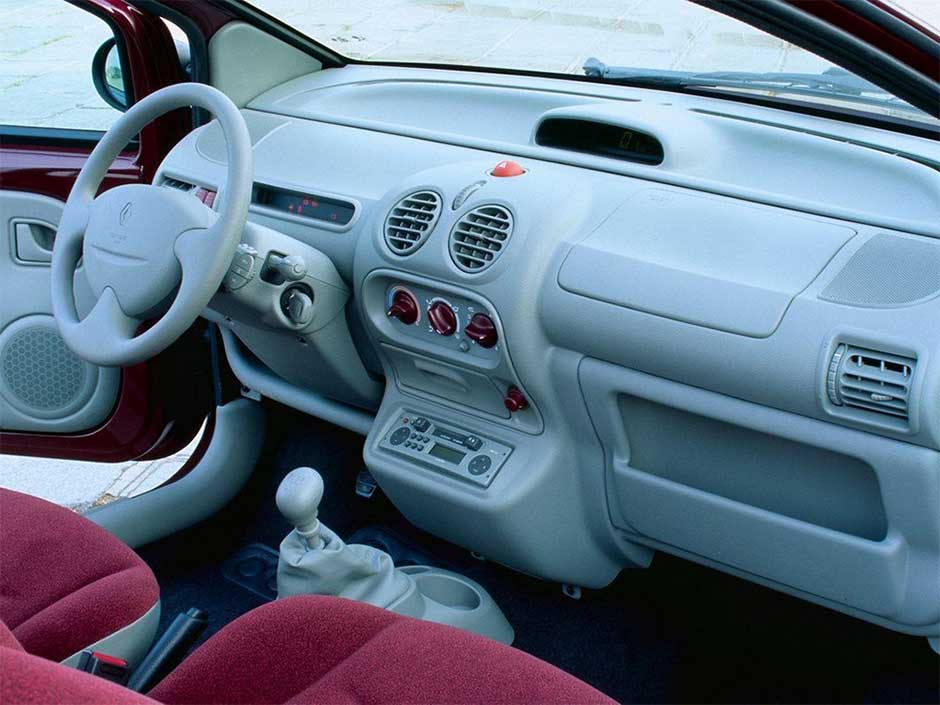
Page 100: Air Vents: Air Outlets
AIR VENTS: air outlets (1/2) 4 centre air vents 1 side window demister outlet 5 control panel 2 left-hand side vent 6 right-hand side vent 3 windscreen demister outlets 7 front occupant footwell heater out- lets…
-
Page 101
AIR VENTS: air outlets (2/2) To remove bad odours from your ve- hicles, only use the systems designed for this purpose. Consult an approved Dealer. Side air vents Centre air vents Air flow Air flow Move wheel 2 fully. Move wheel 4 fully. … -
Page 102: Manual Air Conditioning
MANuAl AIR CoNDITIoNINg (1/3) Distribution of air in the passenger compartment Turn control A. Close the dashboard vents for more effective demisting. All the air is then directed to the wind- screen and front side window demister outlets. The air flow is distributed be- tween all the air vents, the front side window demisting vents, the windscreen demisting vents and the…
-
Page 103
MANuAl AIR CoNDITIoNINg (2/3) Adjusting the ventilation speed Turn control C from 0 to 4. The passenger compartment is ven- tilated by blown air. The blower deter- mines how much air enters but vehicle speed has a slight effect on this. The further the control is positioned to the right, the greater the amount of air blown into the passenger compartment. -
Page 104
MANuAl AIR CoNDITIoNINg (3/3) Prolonged use of this position (iso- lation mode) may mist up the win- dows slightly or cause odours due to the air not being renewed. It is therefore advisable to return to normal operation (external air) by pressing control D when you have passed through the polluted area. -
Page 105: Heating — Air Conditioning
hEATINg – AIR CoNDITIoNINg (1/2) Note: The air conditioning may be used in all conditions but does not operate when the external temperature is low. – Button E not activated (indicator integrated into the button not illu- minated). The air conditioning is not operating. The heating and ventilation controls are the same as a vehicle without air conditioning.
-
Page 106
hEATINg – AIR CoNDITIoNINg (2/2) If no cold air is produced Check that the controls are set correctly and that the fuses are sound. If they are not, switch off the heating and air con- ditioning system (indicator integrated into button E) and contact an approved dealer. -
Page 107: Automatic Climate Control
AuToMATIC ClIMATE CoNTRol (1/9) 12 Heated rear screen with demisting function and heated door mirrors (depending on vehicle). 13 Heated rear screen warning light. 14 Air recirculation control. Information and advice on use: refer to the end of the paragraph on “Heating/ air conditioning”.
-
Page 108
AuToMATIC ClIMATE CoNTRol (2/9) – press button 7 to increase the tem- perature; – press button 4 to decrease the tem- perature. Note: The maximum and minimum settings of 15°C and 27°C allow the system to produce a minimum or maxi- mum temperature, whatever the ambi- ent conditions. -
Page 109
AuToMATIC ClIMATE CoNTRol (3/9) Ambient temperature: (automatic mode) (continued) operation To reach and keep the chosen comfort level and to maintain good visibility, the system controls: – ventilation speed; – air distribution; The displayed temperature values show a comfort level. –… -
Page 110
AuToMATIC ClIMATE CoNTRol (4/9) Adjusting automatic mode Automatic mode is the normal operat- ing mode of the system (AUTO indica- tor light lit on display 5) but you may alter the selections made by the system (air distribution, etc.). These options are explained on the following pages. -
Page 111
AuToMATIC ClIMATE CoNTRol (5/9) ö The air flow is directed towards all the air vents and the pas- senger footwells. ó The air flow is directed mainly towards the footwells. õ Distribution of air in the All the air flow is directed to the demisting vents for the wind- passenger compartment screen and the side windows. -
Page 112
AuToMATIC ClIMATE CoNTRol (6/9) Varying the ventilation speed In automatic mode, the system uses the most suitable amount of air to reach and maintain the desired comfort level. Automatic mode is switched off by pressing buttons 9 and 11. These buttons allow you to increase or decrease ventilation speed. -
Page 113
AuToMATIC ClIMATE CoNTRol (7/9) Rear screen de-icing/ To exit this function, press button 12 again. Demisting automatically stops demisting by default. With the engine running, press button 12, and operating tell-tale 13 comes on. This function permits rapid demisting/ de-icing of the rear screen and de-icing of the door mirrors (on equipped vehi- cles). -
Page 114
AuToMATIC ClIMATE CoNTRol (8/9) Note: if you wish to reduce the air flow (which may produce a certain amount of noise in the passenger compart- ment), press button 11. To exit this function, press either: – button 1 again; – button 6 (the AUTO indicator light on the display will light up). -
Page 115: Air Recirculation Mode
AuToMATIC ClIMATE CoNTRol (9/9) Air recirculation mode Prolonged use of this position may lead to odours, caused by non-renewal of Pressing button 14 activates air recir- air, and the formation of condensation culation (the symbol lights up on the on the windows. display).
-
Page 116: Maintenance
AIR CoNDITIoNINg: information and advice on use Fuel consumption Maintenance It is normal to notice an increase Refer to the Maintenance Document in fuel consumption (especially in for your vehicle for the inspection towns) when the air conditioning is frequency. operating.
-
Page 117: Interior Lighting
INTERIoR lIghTINg luggage compartment light (depending on vehicle) It comes on when the tailgate or one of the doors is opened. Automatic operation of interior lighting (depending on the vehi- cle) Press switch 1 for: – if the doors are unlocked using –…
-
Page 118: Electric Windows
ElECTRIC WINDoWS With the ignition on: – Press the switch for the window concerned to lower it to the desired height; – lift the switch for the window con- cerned to raise it to the desired height. From the driver’s seat From the front passenger seat Operate the switches as follows:…
-
Page 119
MANuAl WINDoW WINDERS Driver’s responsibility Never leave your vehi- cle with the key inside and Manual window winder never leave a child (or a controls pet) unsupervised, even for a short while. The reason for this is that Turn handle 1. the child may endanger himself or others by starting the engine and activating equipment such as the… -
Page 120: Sun Visor/Courtesy Mirrors/Windscreen
SuN VISoR/CouRTESy MIRRoRS/WINDSCREEN Front sun visor Courtesy mirrors 3 heat reflecting windscreen Lower sun visor 1. Depending on the vehicle, the sun This windscreen reflects the sun and visors are fitted with courtesy mirrors, limits the infrared rays entering the pas- these are concealed behind a cover 2.
-
Page 121: Electric Sunroof
ElECTRIC SuNRooF – Never operate the sunroof with the blind closed; – Never drive the vehicle with the sunroof open and the sun blind closed. This system functions with Tilting the sunroof Driver’s responsibility the ignition on – to open: open the sun blind then Never leave a child (or pet) turn knob 2 to position A;…
-
Page 122: Precautions During Use
(e.g. someone’s fingers, an ani- tion of the sunroof. mal’s paw or the branch of a tree, etc.), Consult your RENAULT Dealer for it stops and lowers by several centime- details of possible adaptations. tres.
-
Page 123
PASSENgER CoMPARTMENT SToRAgE/FITTINgS (1/3) Passenger side glove box 1 Dashboard storage Central storage compartment 3 compartment 4 To open, lift catch 2. The cover has storage for pens, tickets etc. You should avoid keeping liquids in this compartment (if a liquid leaks there is a risk of seepage). -
Page 124
PASSENgER CoMPARTMENT SToRAgE/FITTINgS (2/3) Centre console storage Door storage compartments 6 Rear door storage compartment 5 compartments 7 This can be used for storing a mobile ashtray, drinks cans, etc. Nothing should be placed on the floor (area in front of driver) as such objects may slide under the pedal during braking manoeuvres, thus obstruct-… -
Page 125
PASSENgER CoMPARTMENT SToRAgE/FITTINgS (3/3) Front seat storage pocket 8 Sun visor storage 9 grab handle 10 (depending on vehicle) Can be used to hold motorway toll tick- This offers support and can be held ets, maps, etc. when the vehicle is being driven. Do not use it for getting into or out of the vehicle. -
Page 126: Cigar Lighter
AShTRAy/CIgAR lIghTER/ACCESSoRIES SoCkETS Accessories socket Depending on the vehicle, this is lo- cated in the cigar lighter socket 2. Ashtray To open, lift cover 1. To empty, pull the ashtray towards you and it will be re- leased from its housing. To use it: consult the instructions for the equipment which should be kept with the other vehicle documenta-…
-
Page 127: Rear Headrests
REAR hEADRESTS Position for use To refit the headrest Raise the headrest as far as possi- Insert the rods in the holes, press ble to use it in the high position. Press button A of the headrest and lower it button A of lock 1 and lower the head- (move the seat forwards if necessary).
-
Page 128
REAR SEATS: adjustment To adjust the angle of the seatback Pull lever 1. Adjust the angle of the seatback. The rear seats are separate seats. To move forwards or backwards Depending on the vehicle, lift lever 2 to unlock. When the seat is in the required posi- tion, release the lever and ensure that the seat is locked in place. -
Page 129: Rear Seats: Functions
REAR SEATS: functions Tension wheels 4 located under each of the rear seats are used to keep the seats folded down. Unhook the tension wheel from ring 5 and hook it to the rods on the headrest in front. To return the seats Unhook retainer 4 from the headrest rods, and stow it by hooking it into ring 5.
-
Page 130: Rear Bench Seat: Functions
REAR BENCh SEAT: functions When moving the rear seats, ensure that nothing obstructs the anchorage points (passenger’s arm or leg, a pet, gravel, cloth, toys, etc.). When refitting the seat- back, make sure it is cor- rectly locked in place. If seat covers are fitted, make sure these do not prevent the seatback latch from locking in.
-
Page 131: Luggage Compartment
luggAgE CoMPARTMENT To close The tailgate is locked and unlocked at the same time as the doors. Pull down the tailgate using handle 2 inside the tailgate to assist you. To open Once you have lowered the tailgate, Press button 1 and lift the tailgate. release handle 2 and finish closing the tailgate by pressing down on the tail- gate from the outside.
-
Page 132: Rear Parcel Shelf
REAR PARCEl ShElF (1/2) Version with bench seat Version with seats Lift parcel shelf 2. To refit it, proceed in reverse order to To remove, unhook the two straps 1. To remove (bulky loads): removal. – Unhook both straps 3; –…
-
Page 133: Transporting Objects
REAR PARCEl ShElF (2/2) Transporting objects Objects loaded must not protrude beyond area 7 (refer to the information on “Transporting objects in the luggage compartment” in Section 3). If they do, it is essential to remove the Rear seats moved back parcel shelf.
-
Page 134
luggAgE CoMPARTMENT CoVER: utility versions The luggage cover consists of three – The luggage cover is removed. rigid sections. To remove it, in the semi-folded po- It can be used in one of three ways: sition, lift the luggage compartment cover, holding it at either end. -
Page 135: Transporting Objects In The Luggage Compartment
TRANSPoRTINg oBJECTS IN ThE luggAgE CoMPARTMENT locations for anchorage points (depending on the vehicle) These are for securing items trans- ported in the luggage compart- ment (refer to the information on “Transporting objects in the luggage compartment”). Always place the objects to be trans- ported so that their largest side rests against the back of the rear bench seat, for normal loads (Example A), or…
-
Page 136
ToWINg: towing equipment A = 600 mm. Permissible nose weight, maxi- mum permissible towing weight braked and unbraked: Refer to the information on “Weights” in Section 6. Refer to the manufacturer’s instruc- If the towbar ball obscures the reg- tions for information on how to fit istration plate or the rear lights, it and operate the towing equipment. -
Page 137: Roof Bars
RooF BARS When fitting roof bars, at the front of the vehicle, replace the blanking bolts with the mounting bolts supplied with the roof bars. Behind seal 3, position the roof bars in the reinforced area 4 pro- vided. Accessing the mounting points Open the doors.
-
Page 138: Multimedia Equipment
MulTIMEDIA EquIPMENT hands-free telephone The presence and location of this equipment depends on the vehicle’s integrated control multimedia equipment. On equipped vehicles, use micro- 1 Radio; phone 3 and steering column control 2. 2 Steering column control; 3 Microphone. using the telephone We remind you of the need to conform to the legislation To use this equipment, consult the…
-
Page 139
Section 4: Maintenance Bonnet …………… . Engine oil level: . -
Page 140: Bonnet
BONNET (1/2) Unlocking the bonnet catch To open the bonnet, pull handle 1. To open, push tab 2 to the left as you open the bonnet. When working in the engine The engine may be hot compartment, ensure that when carrying out opera- the windscreen wiper stalk tions in close proximity.
-
Page 141: Opening The Bonnet
BONNET (2/2) Closing the bonnet Before closing the bonnet, check to make sure that nothing has been left in the engine compartment. To close the bonnet, replace stay 4 in holder 5. Hold the middle of the bonnet and guide it down to 20 cm above the closed position, then release.
-
Page 142: Engine Oil Level
ENGINE OIL LEVEL: general information It is normal for an engine to use oil for lubrication and cooling of moving parts and it is normal to top up the level be- tween oil changes. Exceeding the maximum engine oil level However, contact an approved dealer if more than 0.5 litres is being consumed The oil level should only be read with…
-
Page 143: Topping Up/Filling
ENGINE OIL LEVEL: topping up/filling (1/2) Special features of 1.2 16V – Unscrew cap 1; – top up the level (as a guide, the ca- engines pacity between the minimum and To unclip the dipstick, lever it by hand maximum reading on dipstick 2 is while pressing engine cover A.
-
Page 144: Engine Oil Change
ENGINE OIL LEVEL: topping up/filling ENGINE OIL ChANGE (2/2) Oil change Filling: take care when Service interval: refer topping up the oil that Maintenance Service Booklet for your no oil drips onto engine vehicle. components — risk of fire. Remember to refit the cap securely Average capacities for oil change (in- as there is a risk of fire if oil splashes cluding oil filter for information).
-
Page 145: Levels
LEVELS (1/3) Topping up Level It is normal for the level to drop as the After any operation on the hydraulic cir- brake shoes become worn, but it must cuit, a specialist must replace the fluid. never drop lower than the “MIN” warn- Only use fluids approved by our ing line on the reservoir 1.
-
Page 146: Coolant Level
LEVELS (2/3) Replacement intervals Checking intervals Refer to the Maintenance Document for Check the coolant level regularly your vehicle. (very severe damage is likely to be caused to the engine if it runs out of coolant). If the level needs to be topped up, only use products approved by our Technical Department which ensure: –…
-
Page 147: Windscreen Washer Reservoir
LEVELS /FILTERS (3/3) Jets Filters To adjust the angle of the jets, pivot the The replacement of filter elements (air little ball using a pin. filter, passenger compartment filter, diesel filter, etc.) is scheduled in the maintenance operations for your vehi- cle.
-
Page 148: Tyre Pressure
TyRE pRESSURE (1/2) F: tyre pressures for the rear wheels (motorway). G: tyre pressure for the emergency spare wheel. H: dimensions of the emergency spare wheel tyre. Label A C: tyre pressures for the front wheels (non-motorway). Open the driver’s door to read it. D: tyre pressures for the rear wheels Tyre pressures should be checked (non-motorway).
-
Page 149
TyRE pRESSURE (2/2) Tyre safety and use of snow chains Refer to the information on “Tyres” in Section 5 for the servicing con- ditions and, depending on the ver- sion, the use of chains. Special note When they need to be re- For vehicles used fully laden placed, only tyres of the (maximum… -
Page 150: Battery
BATTERy Battery Battery access: Label B Observe the indications on the battery: Depending on the vehicle, this is lo- Depending on the vehicle, unclip – 2 Naked flames and smoking are for- cated underneath cover 1. cover A. bidden; – 3 eye protection required; Replacing the battery Handle the battery with care –…
-
Page 151: Bodywork Maintenance
BODyWORk MAINTENANCE (1/2) What you should not do you should A well-maintained vehicle will last longer. It is therefore recommended to Do not degrease or clean mechani- Wash your car frequently, with the maintain the exterior of the vehicle reg- cal components (e.g.
-
Page 152
BODyWORk MAINTENANCE (2/2) Vehicles with a matte paint Using a roller type car wash Respect local regulations about wash- ing vehicles (e.g. do not wash your ve- finish Return the windscreen wiper stalk to hicle on a public highway). the Park position (refer to the informa- This type of paint requires certain pre- Observe the vehicle stopping distances tion on the “Windscreen washer, wiper”… -
Page 153: Interior Trim Maintenance
INTERIOR TRIM MAINTENANCE (1/2) Seat belts Special instructions for sweets or A well-maintained vehicle will have a longer service life. It is therefore ad- chewing gum These must be kept clean. visable to maintain the vehicle interior Put an ice cube on the stain to solidify regularly.
-
Page 154
INTERIOR TRIM MAINTENANCE (2/2) Removing/refitting factory What you should not do fitted removable equipment You are strongly advised not to place in the vehicle items such as air fresheners, perfume etc. near the air vents as these could If you need to remove equipment to damage the dashboard fittings. -
Page 155: Practical Advice
Section 5: Practical advice Puncture …………..Tyre inflation kit .
-
Page 156: Puncture
Puncture Vehicles fitted with an emergency spare wheel smaller than the four other wheels: – Never fit more than one emer- gency spare wheel to the same vehicle. – Replace the emergency spare wheel as soon as possible with a wheel with the same dimensions as the original.
-
Page 157
tYre PreSSure KIt (1/3) Do not attempt to use the The kit is only approved for inflation kit if the tyre has inflating the tyres of the ve- been damaged as a result hicle originally equipped of driving with a puncture. with the kit. -
Page 158
tYre PreSSure KIt (2/3) With the engine running and the – after a maximum of 15 minutes, stop parking brake applied, inflating and read the pressure (on pressure gauge 5). – unroll the hose from the container; note: while the container is empty- –… -
Page 159
tYre PreSSure KIt (3/3) Precautions when using the – Affix the driving recommendation label to the dashboard where it can easily be seen by the driver; The kit should not be operated for more – Put the kit away. than 15 consecutive minutes. –… -
Page 160: Tool Kit
tOOL KIt Hubcap tool 5 or 6 This tool is used to remove the wheel trims. Jack 3 Remove jack 3. When replacing the jack, fold it cor- rectly and position the wheelbrace cor- rectly before replacing it in its position. Storage compartments 2 Tool kit 3 is located in the emergency spare wheel.
-
Page 161: Wheel Trim — Wheel Rims
WHeeL trIM — WHeeLS Wheel trim (example: wheel central wheel trim (example: trim 1) wheel trim 4) Remove the wheel trim using hubcap Remove the wheel trim using hubcap tool 3 (stored in the tool kit) by engag- tool 5 (located in the tool kit) inserting ing the hook in the opening for valve 2.
-
Page 162: Changing A Wheel
cHAngIng A WHeeL (1/2) Start extending jack 2 by hand, turning the handle. Position the head correctly under vertical sill seam 3 nearest to the wheel concerned and marked by an oblong hole. Continue turning the handle to position the baseplate of the jack on the ground correctly.
-
Page 163
cHAngIng A WHeeL (2/2) Fit the emergency spare wheel on the central hub and turn it to locate the mounting holes in the wheel and the hub. If bolts are supplied with the emergency spare wheel, only use these bolts for the emergency spare wheel. -
Page 164: Tyres (Tyre And Wheel Safety, Use In Winter)
tYreS (1/3) tyre and wheel safety When the tyre tread has been worn to the level of the warning strips, they The tyres are the only contact between become visible 2: it is then neces- the vehicle and the road, so it is essen- sary to replace your tyres because the tial to keep them in good condition.
-
Page 165: Tyre Pressures
tYreS (2/3) tyre pressures Fitting new tyres Pressures should be checked when the tyres are cold; ignore higher pressures Tyre pressures must be adhered to (in- which may be reached in hot weather cluding the emergency spare wheel). or following a fast journey. For safety reasons, this op- Pressures must be checked at least If tyre pressures cannot be checked…
-
Page 166: Use In Winter
tYreS (3/3) use in winter – Snow or winter tyres We would recommend that these be – chains fitted to all four wheels to ensure For safety reasons, fitting snow that your vehicle retains maximum chains to the rear axle is strictly adhesion.
-
Page 167: Windscreen Wiper Blades
WInDScreen WIPer BLADeS replacing rear screen wiper blade 6 – Lift wiper arm 5; – pivot the blade until some resistance is met; – remove the blade by pulling it. refitting a front or rear wiper blade To refit the wiper blade, proceed in re- verse order to removal.
-
Page 168: Front Headlights: Changing Bulbs
FrOnt HeADLIgHtS: changing bulbs (1/2) Main beam headlights, The following bulbs can be replaced. However, we would advise you to have dipped beam headlights them replaced by an authorised dealer – remove bulb holder 1 from its hous- if it proves difficult. ing without pulling on the cable;…
-
Page 169
FrOnt HeADLIgHtS: changing bulbs (2/2) Direction indicator lights To return it, proceed in the reverse order to removal. changing a bulb When the bulb has been changed, – unclip cover 3 and remove it; make sure you refit the cover 3 cor- rectly. -
Page 170: Fog Lights, Front Side Lights
FOg LIgHtS, FrOnt SIDe LIgHtS: changing bulbs Front fog lights 1 and front Turn light trim 3 anticlockwise and Release the light 5. remove it. side lights 2 Turn one of the bulb holders 7 anti- Unscrew the two screws 4 (using a flat- clockwise and change the bulbs 6 or 8.
-
Page 171
reAr LIgHtS: changing bulbs (1/4) rear side lights and stop Unclip the bulb holder using tabs 2. 3 Side lights and brake lights Pear shaped, bayonet type P 21/5 V light, indicator lights and fog bulb with two filaments. lights 4 Indicator Note the correct positioning of the Orange pear-shaped, bayonet type… -
Page 172: Reversing Lights
reAr LIgHtS: changing bulbs (2/4) reversing lights 6 Unclip covers 7 and remove them. Turn bulb holder 8 fully anticlockwise and change the bulb 9. Lift the boot lid. To reassemble, proceed in the reverse order to removal. When the bulb has been changed, make sure you refit the cover 7 cor- rectly.
-
Page 173
reAr LIgHtS: changing bulbs (3/4) High-level brake light To return it, proceed in the reverse order to removal. – Remove the blanking covers 10 Check the tabs are correctly locked in inside the tailgate. position. – Press the tabs (using a flat-blade Bulb type: W16W. -
Page 174: Number Plate Lights
reAr LIgHtS: changing bulbs (4/4) number plate lights Disconnect the light, then remove the cover to access bulb 14. Unclip the light by pressing tab 13 Bulb type: W5W. (using a flat-blade screwdriver or simi- lar). The bulbs are under pres- sure and can break when replaced.
-
Page 175
InDIcAtOr LIgHtS: changing bulbs Unclip indicator light 1 (using a flatb- Turn bulb holder 2 a quarter of a turn lade screwdriver or similar) with care. and take out the bulb. Bulb type: WY 5 W. The bulbs are under pres- sure and can break when replaced. -
Page 176: Courtesy Light
InterIOr LIgHtS: changing bulbs (1/2) courtesy light Remove bulb 3 or depending on the ve- hicle, bulbs 3 and 4. Unclip (using a flat-blade screwdriver or Bulb type: W5W similar 1) the transparent cover 2 in the direction shown. The bulbs are under pres- sure and can break when replaced.
-
Page 177
InterIOr LIgHtS: changing bulbs (2/2) Luggage compartment light 5 Press tab 6 to release the lens and access bulb 7. Unclip light 5 by pressing the tabs on Bulb type: W5W. each side (using a flat-blade screw- driver or similar). Disconnect the light. -
Page 178: Connecting A Battery Charger
BAtterY: troubleshooting to avoid all risk of sparks: Only a fully charged and well-main- When many accessories are fitted to tained battery will have a long and the vehicle, have them connected to – Ensure that any consumers are useful service life and enable you to the + after ignition feed.
-
Page 179
BAtterY: troubleshooting (continued) Starting the vehicle using the Check that there is no con- battery from another vehicle tact between leads A and B and that the positive lead A Proceed as follows when starting your is not touching any metal vehicle from another vehicle’s battery: parts on the vehicle supplying the Obtain suitable jump leads (large) from… -
Page 180: Replacing The Battery
rADIO FreQuencY reMOte cOntrOL: BAtterIeS replacing the battery note: It is not advisable to touch the electronic circuit in the key cover when Remove screw 1, open the case at replacing the battery. slot 2 using a coin, and replace bat- tery 3 using a flat-blade screwdriver or similar observing the polarity shown on the back of the cover.
-
Page 181: Fuse Box
FuSeS (1/3) Fuse box clip 3 If electrical equipment does not work, Remove the fuse using tweezers 3, lo- check the condition of the fuses. cated on the back of cover 1 or in glove box 2. Depending on the vehicle, open cover 1 to the left of the steering wheel or glove- To remove the fuse from the tweezers, box 2.
-
Page 182: Interior Lighting
FuSeS (2/3) Allocation of fuses (the presence of fuses DEPENDS ON THE EQUIPMENT LEVEL OF THE VEHICLE) numbers Allocation numbers Allocation numbers Allocation Direction indicator Main beam headlights/ Windscreen wipers/ lights/Diagnostic Horn. 1 and 2 Rev counter. socket. Main beam headlights. Power supply/ Power-assisted Instrument panel.
-
Page 183: Fuses
FuSeS (3/3) Allocation of fuses (the presence of fuses DEPENDS ON THE EQUIPMENT LEVEL OF THE VEHICLE) numbers Allocation numbers Allocation Left-hand main Right-hand side beam headlight and light/Passenger instrument panel compartment indicator light. instrument lighting Right-hand dipped Left-hand side light. beam headlight.
-
Page 184: Towing: Breakdown
1. which you are driving: do not exceed the towing weight for your vehicle. Contact your RENAULT Dealer. When engine Do not leave the tools unse- stopped, steering and brak-…
-
Page 185
tOWIng: breakdown (continued) – Use a rigid towing bar. If a rope or cable is used (where the law allows this), the vehicle being towed must be able to brake. – A vehicle must not be towed if it is not fit to be driven. -
Page 186
FIttIng tHe rADIO radio location 1 tweeter speakers Front door speakers 3 (depending on vehicle) (depending on vehicle) Unclip and remove the cover. The aerial (depending on vehicle), + and – supply Using a flat-blade screwdriver or simi- Consult an approved dealer. connectors and left-hand and righthand lar, unclip grille 2 to access the speaker speaker wires are fixed to the rear face… -
Page 187
FIttIng tHe rADIO (continued) Speakers in rear panels 4 Location of aerial 5 (depending on vehicle) (depending on vehicle) Consult an approved dealer. Consult an approved dealer. – In all cases, it is very important to follow the manufacturer’s instructions carefully. –… -
Page 188: Accessories
AcceSSOrIeS electrical and electronic accessories Before installing this type of accessory, make sure it is compatible with your vehicle. You can get advice from an au- thorised dealer. Connect accessories with a maximum power of 120 watts only. Fire hazard. No work may be carried out on the vehicle’s electrical or radio circuits, except by authorised dealers: an incorrectly connected system may result in damage being caused to the electrical equipment and/or the components connected to it.
-
Page 189: Operating Faults
OPerAtIng FAuLtS (1/5) the following advice will enable you to carry out quick, temporary repairs. For safety reasons you should always contact a renAuLt Dealer as soon as possible. the starter is activated POSSIBLe cAuSeS WHAt tO DO The indicator lights fail to light up and…
-
Page 190
OPerAtIng FAuLtS (2/5) On the road POSSIBLe cAuSeS WHAt tO DO Coolant boiling in the coolant reser- Mechanical fault: cylinder head Stop the engine. voir. gasket damaged, faulty coolant Contact an approved Dealer. pump. Smoke under the bonnet. Short circuit or cooling system leak. Stop, switch off the ignition, stand away from the vehicle and contact an approved Dealer. -
Page 191
OPerAtIng FAuLtS (3/5) On the road POSSIBLe cAuSeS WHAt tO DO Vibrations Tyres not inflated to correct pres- Check the tyre pressures: if this is not the sures, incorrectly balanced or dam- problem, have them checked by an ap- aged. proved dealer. -
Page 192
OPerAtIng FAuLtS (4/5) electrical equipment POSSIBLe cAuSeS WHAt tO DO The wipers do not work. Wiper blades stuck. Free the blades before using the wipers. Faulty electrical circuit. Consult an approved Dealer. The wiper does not stop. Faulty electrical controls. Consult an approved Dealer. -
Page 193
OPerAtIng FAuLtS (5/5) electrical equipment POSSIBLe cAuSeS WHAt tO DO The sunroof does not open/close. Sunroof opening conditions not ful- Apply the opening conditions (refer to the filled. information on the “Electric sunroof” in Section 3). Roof fault. Leave the sunroof closed or close it using the methods described in “Electric sunroof: Electrical fault (discharged battery, Operating fault”… -
Page 194
5.40… -
Page 195: Technical Specifications
Section 6: Technical specifications Vehicle identification plates …………Engine specifications .
-
Page 196: Vehicle Identification Plates
VEHICLE IDENTIFICATION PLATES (1/2) The information shown on the ve- 4 MAM (Maximum Authorised Mass) hicle identification plate should be for front axle. quoted on all correspondence or 5 GTW (Gross train weight: vehicle orders. fully loaded, with trailer). 6 MPAW (Maximim Permissible The presence and location of the in- Weight) for front axle.
-
Page 197
VEHICLE IDENTIFICATION PLATES (2/2) Quote the details given on engine plate C on all communication or orders. C — Engine plate or engine label (location varies depending on engine) 1 Engine type 2 Engine suffix 3 Engine number… -
Page 198: Engine Specifications
Only use the spark plugs specified for your vehicle’s engine. The type should be marked on a label stuck inside the engine compartment. If it is not then contact your RENAULT Dealer. Fitting spark plugs which are not to specification may damage the engine.
-
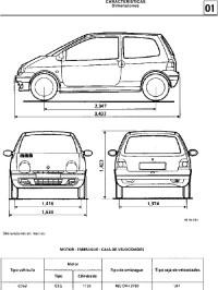
Page 199: Dimensions
DIMENSIONS (in metres) 1.400 / 1.414 0.553 0.767 2.367 1.949 3.687 1.470 (1) 1.386 / 1.400 (1) unladen…
-
Page 200: Weights
WEIGHTS (in kg) The weights indicated for a basic vehicle without options: they vary depending on the your vehicle’s equipment. Consult your approved Dealer. Maximum permissible all-up weight (MMAC) Weights are indicated on the vehicle identification plate (refer to Maximum permissible all-up weight (MMTA) the information on “Vehicle identification plates”…
-
Page 201: Replacement Parts And Repairs
REPLACEMENT PARTS AND REPAIRS Original parts are based on strict specifications and are subject to highly-specialised tests. Therefore, they are of at least the same level of quality as the parts fitted originally. If you always fit genuine replacement parts to your vehicle, you will ensure that it performs well. Furthermore, repairs carried out within the manufacturer’s Network using original parts are guaranteed according to the conditions set out on the reverse of the repair order.
-
Page 202: Service Sheets
SERVICE SHEETS VIN: ……………… Date: Miles (km): Invoice number: Comments/miscellaneous Type of operation: Stamp Service □ …….. □ Anticorrosion check: OK □ Not OK* □ *See specific page Date: Miles (km): Invoice number: Comments/miscellaneous Type of operation: Stamp Service □ …….. □ Anticorrosion check: OK □ Not OK* □…
-
Page 203
SERVICE SHEETS (continued) VIN: ……………… Date: Miles (km): Invoice number: Comments/miscellaneous Type of operation: Stamp Service □ …….. □ Anticorrosion check: OK □ Not OK* □ *See specific page Date: Miles (km): Invoice number: Comments/miscellaneous Type of operation: Stamp Service □ …….. □ Anticorrosion check: OK □ Not OK* □… -
Page 204
SERVICE SHEETS (continued) VIN: ……………… Date: Miles (km): Invoice number: Comments/miscellaneous Type of operation: Stamp Service □ …….. □ Anticorrosion check: OK □ Not OK* □ *See specific page Date: Miles (km): Invoice number: Comments/miscellaneous Type of operation: Stamp Service □ …….. □ Anticorrosion check: OK □ Not OK* □… -
Page 205
SERVICE SHEETS (continued) VIN: ……………… Date: Miles (km): Invoice number: Comments/miscellaneous Type of operation: Stamp Service □ …….. □ Anticorrosion check: OK □ Not OK* □ *See specific page Date: Miles (km): Invoice number: Comments/miscellaneous Type of operation: Stamp Service □ …….. □ Anticorrosion check: OK □ Not OK* □… -
Page 206
SERVICE SHEETS (continued) VIN: ……………… Date: Miles (km): Invoice number: Comments/miscellaneous Type of operation: Stamp Service □ …….. □ Anticorrosion check: OK □ Not OK* □ *See specific page Date: Miles (km): Invoice number: Comments/miscellaneous Type of operation: Stamp Service □ …….. □ Anticorrosion check: OK □ Not OK* □… -
Page 207
SERVICE SHEETS (continued) VIN: ……………… Date: Miles (km): Invoice number: Comments/miscellaneous Type of operation: Stamp Service □ …….. □ Anticorrosion check: OK □ Not OK* □ *See specific page Date: Miles (km): Invoice number: Comments/miscellaneous Type of operation: Stamp Service □ …….. □ Anticorrosion check: OK □ Not OK* □… -
Page 208: Anticorrosion Check
ANTICORROSION CHECk If the continuation of the warranty is subject to repair, it is indicated below. VIN: …………Stamp Corrosion repair operation to be carried out: Date of repair: Repair to be carried out: Stamp Date of repair: Repair to be carried out: Stamp Date of repair: 6.14…
-
Page 209
ANTICORROSION CHECk (continued) If the continuation of the warranty is subject to repair, it is indicated below. VIN: …………Stamp Corrosion repair operation to be carried out: Date of repair: Repair to be carried out: Stamp Date of repair: Repair to be carried out: Stamp Date of repair: 6.15… -
Page 210
ANTICORROSION CHECk (continued) If the continuation of the warranty is subject to repair, it is indicated below. VIN: …………Stamp Corrosion repair operation to be carried out: Date of repair: Repair to be carried out: Stamp Date of repair: Repair to be carried out: Stamp Date of repair: 6.16… -
Page 211
ANTICORROSION CHECk (continued) If the continuation of the warranty is subject to repair, it is indicated below. VIN: …………Stamp Corrosion repair operation to be carried out: Date of repair: Repair to be carried out: Stamp Date of repair: Repair to be carried out: Stamp Date of repair: 6.17… -
Page 212
ANTICORROSION CHECk (continued) If the continuation of the warranty is subject to repair, it is indicated below. VIN: …………Stamp Corrosion repair operation to be carried out: Date of repair: Repair to be carried out: Stamp Date of repair: Repair to be carried out: Stamp Date of repair: 6.18… -
Page 213: Alphabetical Index
AlphAbeticAl index (1/5) changing a wheel…………5.8 – 5.9 ABS ……………2.12 → 2.14 changing gear …………..2.6 accessories……………. 5.34 child restraint/seat ……1.26 – 1.27, 1.29 → 1.35 accessories socket …………3.28 child safety……..1.2, 1.26 – 1.27, 1.29 → 1.35 additional methods of restraint ………. 1.25 child seats……….1.26 – 1.27, 1.29 → 1.35 to the front seat belts ……..1.19 → 1.22 children …………..
-
Page 214
AlphAbeticAl index (2/5) engine immobiliser (switch) ……….2.2 engine oil …………..4.4 → 4.9 handbrake…………….2.7 engine oil capacity ………….4.4 → 4.6 hands-free telephone integrated control ……3.40 engine oil level …………4.4, 4.7 → 4.9 hazard warning lights signal ……….1.39 engine specifications …………6.4 headlight beam adjustment ……….1.61 environment …………… -
Page 215
……..1.2 → 1.4 multimedia equipment …………3.40 remote control electric door locking batteries …………… 5.26 navigation …………….3.40 RENAULT ANTI-INTRUDER DEVICE (RAID) ….1.10 navigation system ………….. 3.40 replacement parts …………..6.7 reverse gear selecting …………….. 2.6 oil change ……………. -
Page 216
AlphAbeticAl index (4/5) roof rack towing ……………… 6.6 roof bars …………… 3.39 breakdown …………5.30 – 5.31 running in …………….2.2 towing equipment ……..3.38, 5.30 – 5.31 towing a caravan ……….5.30 – 5.31, 6.6 towing hitch…………5.6, 5.30 – 5.31 screen wash/wipe ……….. 1.62 – 1.63 towing rings …………… 3.37 seat belt pretensioners ……….1.19 → 1.24 towing weights ………….. -
Page 217
AlphAbeticAl index (5/5) wiper blades …………..5.13 wipers …………….1.64… -
Page 219
à999107058Rí ê ú ä RENAULT S.A.S. SOCIÉTÉ PAR ACTIONS SIMPLIFIÉE AU CAPITAL DE 533 941 113 € / 13-15, QUAI LE GALLO 92100 BOULOGNE-BILLANCOURT R.C.S. NANTERRE 780 129 987 — SIRET 780 129 987 03591 / TÉL. : 0810 40 50 60…
Руководства по ремонту
| В разделе материалов: 21 Показано материалов: 1-10 |
Страницы: 1 2 3 » |
 В данный Официальный файл входит описание и руководства по ремонту — Электрооборудования (Аккумуляторная батарея, фары, приборы заднего освещения, приборы внутреннего освещения, предохранители, системе электронной противоугонной блокировки, звуковой сигнализатор, охранная сигнализация, щиток приборов, регулятор скорости движения, сигнализация, стеклоочистителе и стеклоомыватели, аудиосистема, комутационный блок в салоне, управление открывающимися элементами кузова, электро стеклоподъемники, подушки безопасности, преднатяжители ремней) на автомобиль Renault Twingo.
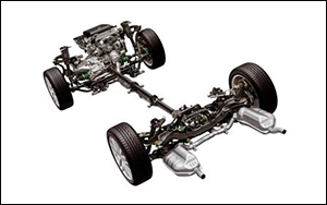 В данный Официальный файл входит описание и руководства по ремонту — несущих элементов (шасси: общие сведения, передние несущие элементы, задние несущие элементы, колеса, шины, рулевое управление, эбу абс) на автомобиль Renault Twingo.
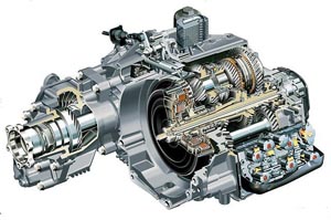 В данный Официальный файл входит описание и руководства по ремонту — Сцепление, механическая коробка передач, роботизированная коробка передач на автомобиль Renault Twingo.
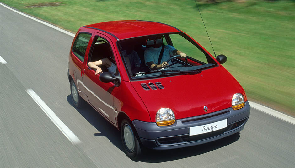
Renault Twingo оригинальное (The driver’s handbook – 82 00 363 172 – NU 642-9 – June 2003 – Edition anglaise / Kvìten 2004 – Edition tchèque / Settembre 2004 – Edition italienne / 1995 3-e Edición Española) руководство по техническому обслуживанию и эксплуатации с бензиновыми двигателями: D7F 1.15 л (1149 см³) 60 л.с./43 кВт, D4F 1.15 л (1149 см³) 75 л.с./55 кВт и C3G 1.2 л (1239 см³) 55 л.с./40 кВт; технические характеристики, устройство, особенности конструкции. Инструкция пользователя легковой автомобиль особо малого класса Рено Твинго с цельнометаллическими несущими кузовами трехдверный хэтчбек переднеприводные модели первого поколения (включая рестайлинги 1998 фаза 2, 2000 фаза 3, 2004 фаза 4) выпуска с 1992 по 2007 год
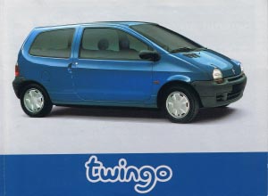
Renault Twingo руководство по эксплуатации, ремонту и техобслуживанию здесь
Renault Twingo (Renault s.a.s 1997 X English version) руководство по ремонту и техобслуживанию для СТО
Renault Twingo 1992-2007 руководство по эксплуатации, техническому обслуживанию и ремонту
ЕСЛИ ВЫ ВИДИТЕ ОШИБКУ 406 Not Acceptable и не видите документ, то скорей всего у Вас IP РФ и его надо сменить, на любой другой страны, с помощью VPN ( Scribd и SlideShare блокируют посетителей с Российским IP).
Renault Twingo замена топливного фильтра/ how change gas filter и свечей зажигания (Рено Твинго 92-07)
Renault Twingo Mark I общая информация (Рено Твинго 1992-2007)
Тормозные колодки
СНЯТИЕ
Отсоедините провод сигнальной лампы износа колодок.
Вдавите поршень, сдвинув рукой плавающую скобу тормоза наружу.
Отвинтите болты направляющих, воспользовавшись двумя ключами.
Эти болты очищать не надо.
Освободите:
— плавающую скобу,
— тормозные колодки.
Проверка
Проверьте:
— состояние и установку пылезащитного кольца поршня и его стопорного кольца,
— состояние пылезащитных чехлов направляющих.
УСТАНОВКА
Отожмите тормозной поршень с помощью приспособления Fre. 823.
Поставьте новые колодки и их пружины, соблюдая направление установки.
Колодка с проводом датчика износа ставится с внутренней стороны.
Поставьте на место скобу и завинтите болт нижней направляющей, смазав его смазкой Loctite FRENBLOC.
Надавите на скобу и установите болт верхней направляющей, смазав его смазкой Loctite FRENBLOC.
Затяните болты направляющих с нужным моментом, начиная с нижнего.
Подсоедините провод сигнальной лампы износа колодок.
Нажмите несколько раз на педаль тормоза, чтобы поршень пришел в соприкосновение с колодками.
Напоминаем вам, что при замене колодок или других работах с этим типом тормозного механизма болты направляющих пальцев надо каждый раз менять и затягивать с моментом от 34 до 38 Нм, начиная с нижнего болта.
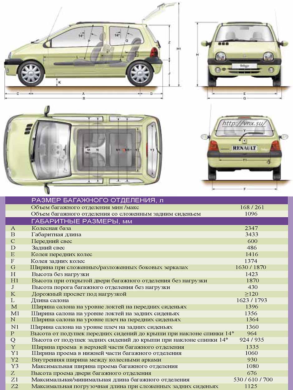
| № | Спецификация / Specs | Данные |
| Габариты (мм/mm) и масса (кг/kg) / Dimensions and Weight | ||
| 1 | Длина / Length | 3433 |
| 2 | Ширина (без/с зеркалами) / Width | 1630/1870 |
| 3 | Высота (загружен/пустой) / Height | 1423 |
| 4 | Колёсная база / Wheelbase | 2347 |
| 5 | Дорожный просвет (клиренс) / Ground clearance | 120 |
| 6 | Снаряжённая масса / Total (curb) weight | 835 |
| Полная масса / Gross (max.) weight | 1260 | |
|
Двигатель / Engine |
||
| 7 | Тип / Engine Type, Code | Бензиновый, жидкостного охлаждения, четырехтактный, D4F |
| 8 | Количество цилиндров / Cylinder arrangement: Total number of cylinders, of valves | 4-цилиндровый, 16V, рядный, SOHC с верхним расположением одного распределительного вала |
| 9 | Диаметр цилиндра / Bore | 69.0 мм |
| 10 | Ход поршня / Stroke | 76.8 мм |
| 11 | Объём / Engine displacement | 1149 см³ |
| 12 | Система питания / Fuel supply, Aspiration | Распределенный впрыск топлива |
| Атмосферный | ||
| 13 | Степень сжатия / Compression ratio | 9.8:1 |
| 14 | Максимальная мощность / Max. output power kW (HP) at rpm | 55 кВт (75 л.с.) при 5500 об/мин |
| 15 | Максимальный крутящий момент / Max. torque N·m at rpm | 107 Нм при 4250 об/мин |
|
Трансмиссия / Transmission |
||
| 16 | Сцепление / Clutch type | Однодисковое, сухое, с диафрагменной нажимной пружиной и гасителем крутильных колебаний, постоянно замкнутого типа |
| 17 | КПП / Transmission type | Quickshift 5 (роботизированное переключение) МКПП 5 пятиступенчатая механическая, двухвальная, с синхронизаторами на всех передачах переднего хода |
О Книге
- Название: Renault Twingo The driver’s handbook / UŞivatelská pøíruèka / Il libretto di istruzioni
- Бензиновые двигатели: D7F 1.15 л (1149 см³) 60 л.с./43 кВт, D4F 1.15 л (1149 см³) 75 л.с./55 кВт и C3G 1.2 л (1239 см³) 55 л.с./40 кВт
- Выпуск с 1992 года
- Серия: «Owner Guide»
- Год издания: 1995/ Июнь 2003/ Май 2004/ Сентябрь 2004
- Автор: Коллектив авторов
- Издательство: «RENAULT S.A.S»
- Формат: PDF
- Страниц в книге: 104+157+164+164
- Размер: 39.76 МБ
- Язык: Английский, Испанский, Чешский, Итальянский — Graecum est, non legitur
- Количество электросхем: 0
Поиск по сайту
Остались вопросы или пожелания? Пишите на почту: support@vnx.su
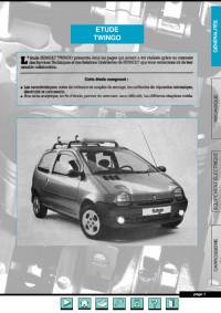
Руководство на французском языке по техническому обслуживанию и ремонту автомобиля Renault Twingo.
- Автор: —
- Издательство: —
- Год издания: —
- Страниц: 200
- Формат: PDF
- Размер: 24,0 Mb
Руководство на испанском языке по техническому обслуживанию и ремонту автомобиля Renault Twingo.
- Автор: —
- Издательство: Renault
- Год издания: —
- Страниц: —
- Формат: PDF
- Размер: 6,2 Mb
Сборник мультимедийных схем на нескольких языках (в том числе русском) электрооборудования автомобиля Renault Twingo 2001-2003 годов выпуска.
- Автор: —
- Издательство: Renault
- Год издания: —
- Страниц: —
- Формат: ISO
- Размер: 28,5 Mb

-
Page 1
TWINGO DRIVER’S HANDBOOK… -
Page 2
RENAULT vehicles. ► ELF lubricants are a major factor in your vehicle’s performance. RENAULT recommends the approved ELF lubricants for your oil changes and top-ups. Contact your RENAULT representative or visit the site: www.lubricants.elf.com The oil born in Formula One… -
Page 3
Throughout the manual, the “approved Dealer” is your RENAULT Dealer. Enjoy driving your new vehicle. Translated from French. Copying or translation, in part or in full, is forbidden unless prior written permission has been obtained from RENAULT, 92 100 Billancourt 2009. -
Page 5
Sections Getting to know your vehicle ……. Driving …………..Your comfort …………Maintenance …………Practical advice ………… Technical specifications ……..Alphabetical index ………. -
Page 7: Table Of Contents
Section 1: Getting to know your vehicle Keys, Remote control: general information, use, deadlocking ……Doors .
-
Page 8
KEY/RADIO FREQUENCY REMOTE CONTROL: general information Key A Radio frequency remote control B 1 Coded key for ignition switch, doors and fuel filler cap. 2 Locking the doors and tailgate. Driver’s responsibility 3 Unlocking the doors and tailgate. Never leave your vehicle 4 Coded key for ignition switch, driv- with the card inside the er’s door and fuel filler cap. -
Page 9
KEY/RADIO FREQUENCY REMOTE CONTROL: general information (continued) Radio frequency remote control operating range This varies according to the environ- ment. It is therefore important when handling the remote control to ensure Replacement and additional keys that you do not lock or unlock the ve- or remote controls. -
Page 10: Locking The Doors
RADIO FREQUENCY REMOTE CONTROL: use Doors are locked and unlocked using remote control unit B. It is powered by a battery which must be replaced (refer to the information on the “Radio frequency remote control: batteries” in Section 5). Locking the doors Unlocking the doors Press locking button 1.
-
Page 11
DEADLOCKING To activate deadlocking Press button 1 twice in quick succes- sion. The hazard warning lights and side in- dicator lights flash five times to indicate that the doors have locked. Deadlocking of the doors/ tailgate (for some countries) This allows you to lock the doors and tailgate and to prevent the doors from being opened with the interior handles (by breaking the window and then trying… -
Page 12: Doors
OpENING AND CLOsING ThE DOORs Lights-on warning buzzer If you have left the lights on after switch- ing off the ignition, a reminder buzzer will sound when the driver’s door or, de- pending on the vehicle, the front doors or tailgate are opened (to prevent dis- charge of the battery, etc.).
-
Page 13: Indicator Light
LOCKING/UNLOCKING ThE DOORs Doors and tailgate status indicator light The indicator light on switch 1 informs you of the closure status of the doors and tailgate: – the indicator light is on when the doors/tailgate are locked; – the indicator light goes out when a door or the tailgate is open (or incor- rectly closed).
-
Page 14
LOCKING/UNLOCKING ThE DOORs (continued) Electric central locking Locking/unlocking from the outside In some cases, the radio frequency remote control may not work: – if the vehicle is located in a zone of high electromagnetic radiation; – if appliances are operating on the same frequency as the remote con- trol (mobile phone, etc.);… -
Page 15
LOCKING/UNLOCKING ThE DOORs (continued) Press switch 1 for more than five sec- onds, then get out of the vehicle with the remote control with you and close the driver’s door. When the door is closed, all the doors and the tailgate will be locked. The vehicle can only be unlocked from the outside with the coded ignition key, for the front left-hand door. -
Page 16: Automatic Locking When Driving
AUTOMATIC LOCKING WhEN DRIVING You can decide whether you want to The door can be unlocked: activate this function. – by opening a door when stationary. To activate Note: if a door is opened, it will auto- matically be locked again when the With the ignition on, press central vehicle reaches a speed of approxi- door locking button 1 for about 5 sec-…
-
Page 17: Headrests
FRONT hEADREsTs To refit the headrest In case the adjustment of the rods has been modified, pull out the rods 3 as far as they will go (ensure they are aligned and clean). In case of difficulty, ensure the notches face forwards. Insert the headrest rods into the holes (tilt the seatback backwards if neces- sary).
-
Page 18
FRONT hEADREsTs (continued) Fixed headrest (without button 1) To raise the headrest Press button 2 and lift the headrest to release it. To refit the headrest Insert the headrest rods into the holes (tilt the seatback backwards if neces- The headrest is a safety sary). -
Page 19: Rear Headrests
REAR hEADREsTs position for use To refit the headrest Raise the headrest as far as possible Insert the rods in the holes, press but- to use it in the high position. Press but- ton A of the headrest and lower it (move ton A of lock 1 and lower the headrest the seat forwards if necessary).
-
Page 20: Front Seats
FRONT sEATs Adjusting the height of the To move forwards or To tilt the seatback driver’s seat backwards Move handle 5 and tilt the seatback to the desired position. (depending on the vehicle) Move the lever 2 or handle 4 (passen- Move lever 3.
-
Page 21
FRONT sEATs (continued) Table function When placing the front seat- back in the table position, it Depending on the vehicle, the passen- is essential to deactivate ger seatback may be folded down onto the passenger air bag (refer the seat base to create a table: to Section 1: “Deactivating the front –… -
Page 22
FRONT sEATs (continued) Access to the rear seats For safety reasons, carry out any adjustments when Move handle 4, 7 or 8 (depending on Check that no object or the vehicle is not being vehicle), tilt the seatback and slide the person prevents the front driven. -
Page 23: Seat Belts
sEAT BELTs Adjusting your driving Always wear your seat belt when trav- elling in your vehicle. You must also position comply with the legislation of the par- – sit well back in your seat (having ticular country you are in. first removed your coat or jacket).
-
Page 24
sEAT BELTs (continued) If your seat belt becomes completely jammed: – pull the belt slowly but firmly so that just over 3 cm unwinds; – then allow the seat belt to rewind au- tomatically; – unwind it again; – if there is still a problem, contact an approved Dealer. -
Page 25: Rear Seat Belts
REAR sEAT BELTs Rear side seat belts Slowly unwind belt 1. Click buckle 2 into the catch 3. The belts are locked, unlocked and adjusted in the same way as the front belts. Check that the rear seat belts are positioned and op- Rear seat functions: erating correctly each time Refer to the information on the “Rear…
-
Page 26
sEAT BELTs The following information applies to the vehicle’s front and rear seat belts. – No modification may be made to the component parts of the restraint system (belts and seats and their mountings) fitted originally. For special operations (e.g. fitting child seats) contact an approved Dealer. –… -
Page 27: Methods Of Restraint In Addition To The Front Seat Belts
METhODs OF REsTRAINT IN ADDITION TO ThE FRONT sEAT BELTs These are: – Have the entire restraint – pretensioners; system checked following an accident. – force limiters; – No operation whatso- – air bags for driver and front pas- ever is permitted on any part of senger;…
-
Page 28
METhODs OF REsTRAINT IN ADDITION TO ThE FRONT sEAT BELTs (continued) Force limiter Air bags for driver and front passenger Above a certain severity of impact, this mechanism is used to limit the force of Fitted to the driver and passenger side. the belt against the body so that it is at The presence of this equipment is in- an acceptable level. -
Page 29
METhODs OF REsTRAINT IN ADDITION TO ThE FRONT sEAT BELTs (continued) Operation Operating faults å The air bag system is only operational Warning light 2 will light up on when the ignition is switched on. the instrument panel when the ignition If a severe frontal impact occurs, the is switched on and then go out after a air bag(s) deploy(s) rapidly, cushion-… -
Page 30
METhODs OF REsTRAINT IN ADDITION TO ThE FRONT sEAT BELTs (continued) All of the warnings below are given so that the air bag is not obstructed in any way when it is deployed and also to pre- vent the risk of serious injuries caused by items which may be dislodged when the air bag deploys. Warnings concerning the driver’s air bag –… -
Page 31: Methods Of Restraint In Addition To The Rear Seat Belts
– To avoid incorrect triggering of the system which may cause injury, only qualified RENAULT Network personnel may work on the pre- tensioner and air bag system. 1.25…
-
Page 32: Side Protection Devices
sIDE pROTECTION DEVICEs side air bags These air bags may be fitted to the front seats and are deployed at the sides of the seats (door side) to protect the oc- cupants in the event of a severe side impact. A marking on the seat informs you of the presence of this device.
-
Page 33: Additional Methods Of Restraint
– When selling or lending the vehicle, inform the user of these points and hand over this driver’s handbook with the vehicle; – When scrapping your vehicle, contact your RENAULT Dealer for disposal of the gas generator(s). 1.27…
-
Page 34: Child Safety: General Information
ChILD sAFETY general information Carrying children Using a child seat The level of protection offered by the Children, and adults, must be correctly Set a good example by always fas- child seat depends on its ability to re- seated and strapped in for all journeys. tening your seat belt and teaching strain your child and on its installation.
-
Page 35
ChILD sAFETY choosing a child seat Rear-facing child seats Forward-facing child seats Booster cushions A baby’s head is, proportionally, heavier The child’s head and abdomen need From 15 kg or 4 years, the child can than that of an adult and its neck is very to be protected as a priority. -
Page 36
ChILD sAFETY: choosing a child seat mounting Choosing the attachment Attachment using the ISOFIX Do not use the child seat system There are two ways of attaching child if it may unfasten the seat Authorised ISOFIX child seats are ap- seats: via the seat belt or using the belt restraining it: the base proved in accordance with regulation… -
Page 37
ChILD sAFETY: choosing a child seat mounting (continued) The two rings 1 are located between the seatback and the seat base of the The ISOFIX anchorage seat or bench seat and are identified by points have been exclu- a marking. sively designed for child To ensure your child seat can be easily seats with the ISOFIX… -
Page 38
ChILD sAFETY: choosing a child seat mounting (continued) The third ring is used to attach the upper strap on some child seats. Fit the hook of the strap onto ring 3 (for RIsK OF DEATh OR the rear seats) or 4 (for the front seats) sERIOUs INJURY: before and pull the strap. -
Page 39: Fitting A Child Seat
ChILD sAFETY: fitting a child seat In the front seat In the rear side seat Some seats are not suitable for fitting child seats. The diagram on the follow- The laws concerning children travel- A carrycot can be installed across the ing page shows you how to attach a ling in this seat differ in every coun- vehicle and will take up at least two…
-
Page 40
ChILD sAFETY: Fitting a child seat (continued) Version with separate seats ³ Check the status of the air bag before fitting a child seat or allowing a passenger to use the seat. Child seat attached using the IsOFIX mounting ü Seat which allows an ISOFIX child seat to be fitted. -
Page 41
ChILD sAFETY: Fitting a child seat (continued) Bench seat version ³ Check the status of the air bag before fitting a child seat or allowing a passenger to use the seat. Child seat attached using the IsOFIX mounting ü Seat which allows an ISOFIX child seat to be fitted. -
Page 42
ChILD sAFETY: Fitting a child seat (continued) The table below summarises the information already shown on the diagram on the previous page, to ensure the regula- tions in force are respected. Type of child seat Weight of passenger front seat size IsOFIX Rear side seats (3) (version with the child… -
Page 43
ChILD sAFETY: Fitting a child seat (continued) X = Seat not suitable for fitting child seats. U = Seat allowing a child seat with “Universal” approval to be attached by seat belt; check that it can be fitted correctly. IUF/IL = On equipped vehicles, seat which allows a child seat with “universal/semi-universal or vehicle specific” approval to be at- tached using the ISOFIX device;… -
Page 44
ChILD sAFETY: Fitting a child seat (continued) The table below summarises the information already shown on the diagram on the previous page, to ensure the regula- tions in force are respected. Rear side seats Type of child seat Weight of seat size passenger front (bench seat version) -
Page 45
ChILD sAFETY: Fitting a child seat (continued) X = Seat not suitable for fitting child seats. U = Seat allowing a child seat with “Universal” approval to be attached by seat belt; check that it can be fitted correctly. IUF/IL = On equipped vehicles, seat which allows a child seat with “universal/semi-universal or vehicle specific” approval to be at- tached using the ISOFIX device;… -
Page 46: Deactivating/Activating The Front Passenger Air Bag
ChILD sAFETY: deactivating/activating the front passenger air bag Deactivating the front To deactivate the restraint devices DANGER supplementary to the front passen- passenger airbags Since front passenger air ger seat belt: switch off the ignition, bag triggering and the po- press and turn lock 1 to the OFF posi- (on equipped vehicles) sition of a rear-facing child…
-
Page 47
ChILD sAFETY: deactivating/activating the front passenger air bag Activating the front Operating faults passenger air bags If the front passenger air bag activation/ You should reactivate the air bag as deactivation system is faulty, child seats soon as you remove the child seat from must NOT be fitted to the front seat. -
Page 48
DRIVER’s pOsITION, LEFT-hAND DRIVE 9 10 11 26 25 24 19 18 17 1.42… -
Page 49
DRIVER’s pOsITION, LEFT-hAND DRIVE (continued) The equipment fitted, described below, DEpENDs ON ThE VERsION AND COUNTRY. 1 Side window demister outlet. 10 Instrument panel. 20 Accessories socket or cigar lighter and ashtray. 2 Side air vent. 11 Display: – clock and temperature; 21 Handbrake. -
Page 50
DRIVER’s pOsITION, RIGhT-hAND DRIVE 12 13 1.44… -
Page 51
DRIVER’s pOsITION, RIGhT-hAND DRIVE (continued) The equipment fitted, described below, DEpENDs ON ThE VERsION AND COUNTRY. 1 Side window demister outlet. 11 Rev counter. 19 Parking distance control switch. 2 Side air vent. 12 Stalk for: 20 Heating and ventilation controls. –… -
Page 52
INsTRUMENT pANEL: warning lights The presence and operation of the warning and indicator lights described below DEpEND ON ThE EQUIpMENT AND ThE COUNTRY. handbrake on and brake cir- Variable power-assisted cuit incident warning light steering warning light If it comes on during braking and is ac- This comes on when the ignition is û… -
Page 53
INsTRUMENT pANEL: warning lights (continued) The presence and operation of the warning and indicator lights described below DEpEND ON ThE EQUIpMENT AND ThE COUNTRY. À Ü Oil pressure warning light Not used Ä This lights up when the ignition is Toxic Fume Filter system switched on and goes out after a few Warning Light… -
Page 54
INsTRUMENT pANEL: warning lights (continued) The presence and operation of the warning and indicator lights described below DEpEND ON ThE EQUIpMENT AND ThE COUNTRY. Anti-lock braking warning Not used light This lights up when the ignition is ç switched on and goes out after a few seat belt reminder light seconds. -
Page 55
INsTRUMENT pANEL: warning lights (continued) The presence and operation of the warning and indicator lights described below DEpEND ON ThE EQUIpMENT AND ThE COUNTRY. Warning light side light tell-tale light © This lights up when the igni- tion is switched on and goes out after a Dipped beam headlight tell- few seconds. -
Page 56
INsTRUMENT pANEL: displays and indicators Rev counter 1 (graduations x100) sequential gearbox display 3 Information display 5 (depending on vehicle) This indicates the gear engaged (de- Depending on the vehicle, it includes: pending on the vehicle). Refer to the in- –… -
Page 57: Trip Computer And Warning System
TRIp COMpUTER AND WARNING sYsTEM Display selection key 1 Instrument panel in miles Press button 2 repeatedly to scroll It is possible to switch to km/h. through the following information: Press button 2 and switch on the igni- – total mileage recorder; tion.
-
Page 58
TRIp COMpUTER AND WARNING sYsTEM (continued) The display of information shown below DEpENDs ON ThE VEhICLE EQUIpMENT AND COUNTRY. Examples of display selections Interpreting the display by repeatedly pressing button 2 Total mileage recorder. Trip mileage recorder. speed limiter or cruise control programmed speed. Refer to the information on the “Speed limiter”… -
Page 59
TRIp COMpUTER AND WARNING sYsTEM (continued) The display of information shown below DEpENDs ON ThE VEhICLE EQUIpMENT AND COUNTRY. Examples of display selections Interpreting the display selected by repeatedly pressing button 2 service distance Distance remaining until the next service. There are several scenarios: –… -
Page 60: Steering Wheel
sTEERING WhEEL Adjusting the steering wheel Depending on the vehicle, the steering wheel position is adjustable. Never leave the steering wheel on Hold the steering wheel with one hand, full lock when the vehicle is station- ary. lift lever 1 and position the steering wheel as desired.
-
Page 61: Clock And Exterior Temperature
CLOCK AND EXTERIOR TEMpERATURE Resetting the clock Vehicle with button 1: – Press button 1 for approximately three seconds; – when the hour flashes, press button 1 again to adjust it; – wait approximately three seconds, the minutes will flash, press button 1 to adjust them;…
-
Page 62: Time And External Temperature
TIME AND EXTERIOR TEMpERATURE (continued) Resetting the clock External temperature indicator With the ignition on, press button: H for the hours; special note: M for the minutes. When the external temperature is be- Note: for vehicles which are not fitted tween –3°C and +3°C, the °C figures with buttons H and M, refer to the spe- flash (indicates risk of ice formation).
-
Page 63: Rear View Mirrors
REAR VIEW MIRRORs Door mirrors with electrical heated door mirrors Interior rear view mirror adjustment: (depending on vehicle) Its position can be adjusted. When driv- The door mirrors are de-iced when ing at night, to avoid being dazzled by With the ignition on, position control 1 the rear screen demisting/de-icing is the headlights of the vehicle behind, active.
-
Page 64: Exterior Lighting And Signals
EXTERIOR LIGhTING AND sIGNALs switching on the side Adjusting the brightness of lights the instrument panel lighting Turn the end of stalk 1 until the symbol Turn control 3 downwards to reduce the Before driving at night, is opposite mark 2. brightness and upwards to increase it.
-
Page 65
EXTERIOR LIGhTING AND sIGNALs (continued) Automatic operation see-me-home lighting feature (de- pending on vehicle) With the engine running on vehicles fitted with a light sensor, the dipped This function (useful, for example, for beam headlights come on automatically opening a gate, garage, etc.) enables as light begins to fade;… -
Page 66: Main Beam Headlights
EXTERIOR LIGhTING AND sIGNALs (continued) Lights-on warning buzzer A warning buzzer will sound when the driver’s door is opened and the lights are left on after the ignition has been switched off (to prevent the battery run- ning down, etc.). á…
-
Page 67: Front Fog Lights
EXTERIOR LIGhTING AND sIGNALs (continued) Rear fog light switching off the lights Turn centre ring 4 on stalk A – stalk A: return the centre ring 4 to its or B, depending on vehicle, until the initial position. symbol faces mark 5. –…
-
Page 68: Electric Beam Height Adjustment
ELECTRIC BEAM hEIGhT ADJUsTMENT Examples of positions for adjusting control A according to the load All versions except Commercial vehicles commercial vehicles Driver only Driver alone or with front passenger On vehicles fitted with this function, con- Driver with one front trol A allows you to adjust the height of passenger and two rear –…
-
Page 69: Audible And Visual Signals
AUDIBLE AND VIsUAL sIGNALs Depending on the vehicle, the hazard warning lights may come on automati- cally under deliberate heavy decelera- tion. In this case, the hazard warning lights may be switched off by pressing switch 2 once. Direction indicators Move stalk 1 parallel to the steering wheel and in the direction you are going to turn it.
-
Page 70: Windscreen Wiper
WINDsCREEN WAsh/WIpE Vehicles with automatic wiper function With the engine running, move stalk 1: A park; B automatic wiper function: When this position is selected, the system detects the presence of water on the windscreen and triggers wiping at a suitable wiping speed. It is possible to change the time be- tween sweeps by turning ring 2;…
-
Page 71: Windscreen Washer
WINDsCREEN WAsh/WIpE (continued) In frosty weather, make sure that the wiper blades are not stuck by ice (risk of motor overheating). Keep an eye on the condition of the blades. Replace the wiper blades as soon as they begin to lose efficiency (approximately once a year).
-
Page 72: Special Note
REAR sCREEN WAsh/WIpE heated rear screen With the engine running, press button 2 (the integrated indicator on the button will come on). This function demists the rear screen and the electric door mirrors (if these are fitted to the vehicle). The demist function is stopped in two ways: –…
-
Page 73: Fuel Tank
FUEL TANK Fuel grade Diesel version It is essential to use diesel fuel that Use a high grade fuel with the appro- conforms with the information given on priate octane rating as defined by the the label inside cover A. particular standards in force in your country.
-
Page 74
FUEL TANK (continued) Filling with fuel petrol and diesel versions When the pump cuts out automatically petrol versions at the end of the filling procedure, a Using leaded petrol will damage the maximum of two further filling attempts antipollution system and may lead to a may be made, as there must be suffi- loss of warranty. -
Page 75
Section 2: Driving (Advice on use relating to fuel economy and the environment) Running in — Ignition switch …………Starting/Stopping the engine . -
Page 76: Running In/Ignition Switch
RUNNING IN/IGNItIoN SwItch Petrol version “on” position: third position Up to 600 miles (1,000 km), do not The ignition is switched on: exceed 78 mph (130 km/h) in top gear – petrol version: you can start the ve- or 3,000 to 3,500 rpm. hicle;…
-
Page 77: Starting/Stopping The Engine
StARtING/StoPPING the eNGINe Starting the engine Stopping the engine – Petrol injection With the engine idling, turn the key back to the “Stop” position. engine warm or cold: – turn the key to the start position without depressing the accel- erator;…
-
Page 78
SPecIAl NoteS oN PetRol veRSIoNS The following operating conditions: If you notice any of the above operating faults, have the necessary repairs car- – driving for long periods when the low ried out as soon as possible by an ap- fuel level warning light is lit;… -
Page 79: Special Features Of Diesel Versions
However, if after a few seconds and several attempts the engine fails to start, contact a RENAULT Dealer. Do not park the vehicle or run the engine in locations where combustible sub-…
-
Page 80: Gear Lever/Power-Assisted Steering
GeAR leveR/PoweR-ASSISteD SteeRING vehicles with sequential gear- Power-assisted steering box: refer to the information on the Never drive with an inadequately “Quickshift gearbox” in Section 2. charged battery. variable power-assisted steering (depending on vehicle) It is equipped with a system which adapts the level of assistance to the ve- hicle speed.
-
Page 81: Handbrake
hANDBRAKe to apply: Pull upwards, check that the vehicle is properly immobilised. to release: Pull the lever up slightly, press button 1 and then lower the lever to the floor. The red warning light on the instrument panel will come on if you are driving with an incorrectly released handbrake.
-
Page 82: Engine Adjustments
ADvIce: antipollution, fuel economy and driving Maintenance engine adjustments By virtue of its design, moderate fuel consumption and initial settings, your It is important to remember that failure to – ignition: this does not require ad- vehicle conforms to current antipol- respect antipollution regulations could justment.
-
Page 83
ADvIce: antipollution, fuel economy and driving (continued) exhaust gas monitoring – Brake as little as possible. If you an- ticipate an obstacle or bend in ad- system vance, you may then simply release The exhaust gas monitoring system the accelerator pedal. will detect any operating faults in the –… -
Page 84
ADvIce: antipollution, fuel economy and driving (continued) – For vehicles fitted with air condi- tioning, it is normal to observe an increase in fuel consumption (es- pecially in city conditions) when it is used. For vehicles fitted with manual air conditioning, switch off the system when it is not required. -
Page 85: Environment
This commitment is illustrated by the less fuel (eg. 140 g/km, equivalent to the vehicle components have been de- Renault eco² group signature. 5.3 l/100 km for a diesel vehicle). signed to enable them to be recycled. Our vehicles are also equipped with a…
-
Page 86: Driving Correction Devices
DRIvING coRRectIoN DevIce ABS (Anti-lock Braking operating faults: Depending on the vehicle, this is com- posed of: System) © – ABS (anti-lock braking system); – If indicator lights Under heavy braking, the ABS prevents – electronic stability program (eSP) light up on the instrument panel, the wheels from locking, allowing the with understeer control and trac- braking is still operational but…
-
Page 87: Electronic Stability Program
DRIvING coRRectIoN DevIce (continued) electronic stability program electronic Stability Program (eSP) traction control (ASR) (eSP) with understeer control This system helps you to keep control This system helps to limit wheelspin of and traction control (ASR) of the vehicle in critical driving condi- the drive wheels and to control the ve- tions (avoiding an obstacle, loss of grip hicle when pulling away accelerating or…
-
Page 88: Emergency Brake Assist
DRIvING coRRectIoN DevIce (continued) Special note on vehicles with a emergency brake assist Quickshift gearbox This is an additional system to ABS When driving on some roads with low which helps reduce vehicle stopping surface grip (grass, snow, mud, etc.), distances.
-
Page 89
cRUISe coNtRol-SPeeD lIMIteR: limiter function controls Switching on The speed limiter function helps you stay within the driving speed limit that Press switch 1 on the side showing 1 Main “On/Off” switch. you choose, known as the limit speed. Warning light 6 comes on and dashes 2 Limit speed activation, storage and appear on the instrument panel to in-… -
Page 90: Speed Limiter
cRUISe coNtRol — SPeeD lIMIteR: limiter function (continued) varying the limit speed limited speed cannot be maintained When driving down a steep gradient, You can vary the limit speed by press- the system is unable to maintain the ing switch 2 (+) repeatedly to increase limit speed: the stored speed will flash the speed or switch 3 (-) to decrease it.
-
Page 91
cRUISe coNtRol — SPeeD lIMIteR: limiter function (continued) Recalling the limit speed If a speed has been stored, it can be re- called by pressing switch 5 (R). Putting the function on Switching off the function standby The speed limiter function is deacti- vated if you press switch 1: in this case The speed limiter function is suspended … -
Page 92
cRUISe coNtRol — SPeeD lIMIteR: cruise control function This function is an addi- tional driving aid. However, the function does not take the place of the driver. Therefore, it can under no circum- controls The cruise control function helps you to stances replace the driver’s respon- maintain your driving speed at a speed sibility to respect speed limits and to… -
Page 93: Cruise Control
cRUISe coNtRol — SPeeD lIMIteR: cruise control function (continued) Switching on Activating cruise control Driving Press switch 1 on the side showing At a steady speed (above 20 mph Once a cruising speed is stored and (30 km/h)) press switch 2 (+) or 3 the cruise control function is active, (- ): the function is activated, the cur- you may lift your foot off the accelera-…
-
Page 94
cRUISe coNtRol — SPeeD lIMIteR: cruise control function (continued) exceeding the cruising speed The cruising speed may be exceeded at any time by depressing the accelera- tor pedal. While it is being exceeded, the cruising speed flashes on the in- strument panel. -
Page 95
cRUISe coNtRol — SPeeD lIMIteR: cruise control function (continued) Returning to the cruising speed If a speed is stored, it can be recalled, once you are sure that the road condi- tions are suitable (traffic, road surface, weather conditions, etc.). With a vehicle speed above 20 mph (30 km/h), press switch 5 (R). -
Page 96: Selector Lever
QUIcKShIFt GeARBoX Selector lever 1 Gear shift pattern Display – This allows you to engage first gear, A/M to change mode (automatic/ 2 automatic mode to select reverse and neutral and to manual) change gear in manual mode. + to change up a gear 3 selected gear display –…
-
Page 97
QUIcKShIFt GeARBoX (continued) operation Starting Switch on the ignition. The display shows N (neutral) and A (automatic mode). The display on the instrument panel Forwards gear switches on. If neutral (N) is displayed, start the engine but do not depress the –… -
Page 98
QUIcKShIFt GeARBoX (continued) Driving in automatic mode changing mode By pushing the lever forwards twice you can move up two gears at a time Each time the ignition is switched on, You can change mode at any time (unless this causes low engine speeds). automatic mode is selected by default by pushing the lever to the left. -
Page 99
QUIcKShIFt GeARBoX (continued) Parking Audible warning To park the vehicle with a gear en- If you hold the vehicle on a slope for gaged (on a slope, for example): before too long without applying the brakes or switching off the engine, check that a handbrake you will strain the system gear other than N is displayed on the and there is a risk that the clutch will… -
Page 100
QUIcKShIFt GeARBoX (continued) operating faults towing the vehicle Ò If the gearbox is stuck in a gear: When driving, if this warning light comes on together with – Switch on the ignition; © warning light , this indicates a – select neutral with the brake pedal system fault. -
Page 101: Parking Distance Control
PARKING DIStANce coNtRol operating principle Ultrasonic sensors, fitted in the vehi- cle’s rear bumper, measure the dis- tance between the vehicle and an ob- stacle when reversing. This measurement is indicated by beeps which become more frequent the closer you come to the obstacle, until they become a continuous beep when This function is an addi- the vehicle is approximately 30 centi-…
-
Page 102
PARKING DIStANce coNtRol (continued) Prolonged deactivation of the system You can deactivate the system for pro- longed periods by pressing the switch for longer than approximately three seconds. The warning light built into the switch remains lit constantly. Once deactivated, the system can be reactivated by pressing the button again for longer than approximately three seconds. -
Page 103: Your Comfort
Section 3: Your comfort Air vents…………… Heating and air conditioning .
-
Page 104
AIR VENTS (air outlets) 4 centre air vents 1 side window demister outlet 5 control panel 2 left-hand side vent 6 right-hand side vent 3 windscreen demister outlets 7 front occupant footwell heater outlets… -
Page 105: Air Vents
AIR VENTS (continued) To remove bad odours from your ve- hicles, only use the systems designed for this purpose. Consult an approved Dealer. Side air vents Centre air vents Air flow Air flow Move wheel 2 fully. Move wheel 4 fully. : maximum air flow : maximum air flow : closed.
-
Page 106: Manual Air Conditioning
MANuAl AIR CoNDITIoNINg Distribution of air in the passenger compartment Turn control A. Close the dashboard vents for more effective demist- ing. All the air is then directed to the wind- screen and front side window demister outlets. The air flow is distributed be- tween all the air vents, the front side window demisting vents, the windscreen demisting vents and the…
-
Page 107
MANuAl AIR CoNDITIoNINg (continued) Adjusting the ventilation speed Turn control C from 0 to 4. The passenger compartment is ven- tilated by blown air. The blower deter- mines how much air enters but vehicle speed has a slight effect on this. The further the control is positioned to the right, the greater the amount of air blown into the passenger compart-… -
Page 108
MANuAl AIR CoNDITIoNINg (continued) Prolonged use of this position (iso- lation mode) may mist up the win- dows slightly or cause odours due to the air not being renewed. It is therefore advisable to return to normal operation (external air) by pressing control D when you have passed through the polluted area. -
Page 109: Heating And Air Conditioning
HEATINg – AIR CoNDITIoNINg Note: The air conditioning may be used in all conditions but does not operate when the external temperature is low. – Button E not activated (indicator integrated into the button not illu- minated). The air conditioning is not operating. The heating and ventilation controls are the same as a vehicle without air conditioning.
-
Page 110
HEATINg – AIR CoNDITIoNINg (continued) If no cold air is produced Check that the controls are set correctly and that the fuses are sound. If they are not, switch off the heating and air con- ditioning system (indicator integrated into button E) and contact an approved dealer. -
Page 111: Automatic Climate Control
AuToMATIC ClIMATE CoNTRol 12 Heated rear screen with demisting function and heated door mirrors (depending on vehicle). 13 Heated rear screen warning light. 14 Air recirculation control. Information and advice on use: refer to the end of the paragraph on “Heating/ air conditioning”.
-
Page 112
AuToMATIC ClIMATE CoNTRol (continued) – press button 7 to increase the tem- perature; – press button 4 to decrease the tem- perature. Note: The maximum and minimum settings of 15°C and 27°C allow the system to produce a minimum or maxi- mum temperature, whatever the ambi- ent conditions. -
Page 113
AuToMATIC ClIMATE CoNTRol (continued) Ambient temperature: (automatic mode) (continued) operation To reach and keep the chosen comfort level and to maintain good visibility, the system controls: – ventilation speed; The displayed temperature values – air distribution; show a comfort level. –… -
Page 114
AuToMATIC ClIMATE CoNTRol (continued) Adjusting automatic mode Automatic mode is the normal operat- ing mode of the system (AUTO indica- tor light lit on display 5) but you may alter the selections made by the system (air distribution, etc.). These options are explained on the following pages. -
Page 115: Passenger Compartment
AuToMATIC ClIMATE CoNTRol (continued) ö The air flow is directed to- wards all the air vents and the passenger footwells. ó The air flow is directed mainly towards the footwells. õ Distribution of air in the All the air flow is directed to the demisting vents for the passenger compartment windscreen and the side windows.
-
Page 116
AuToMATIC ClIMATE CoNTRol (continued) Varying the ventilation speed In automatic mode, the system uses the most suitable amount of air to reach and maintain the desired comfort level. Automatic mode is switched off by pressing buttons 9 and 11. These buttons allow you to increase or decrease ventilation speed. -
Page 117
AuToMATIC ClIMATE CoNTRol (continued) Rear screen de-icing/ To exit this function, press button 12 again. Demisting automatically stops demisting by default. With the engine running, press but- ton 12, and operating tell-tale 13 comes This function permits rapid demisting/ de-icing of the rear screen and de-icing of the door mirrors (on equipped vehi- cles). -
Page 118
AuToMATIC ClIMATE CoNTRol (continued) Note: if you wish to reduce the air flow (which may produce a certain amount of noise in the passenger compart- ment), press button 11. To exit this function, press either: – button 1 again; – button 6 (the AUTO indicator light on the display will light up). -
Page 119: Air Recirculation Mode
AuToMATIC ClIMATE CoNTRol (continued) Air recirculation mode Prolonged use of this position may lead to odours, caused by non-renewal of Pressing button 14 activates air recir- air, and the formation of condensation culation (the symbol lights up on the on the windows. display).
-
Page 120: Maintenance
AIR CoNDITIoNINg: information and advice on use Fuel consumption Maintenance It is normal to notice an increase Refer to the Maintenance Service in fuel consumption (especially in Booklet for your vehicle for the in- towns) when the air conditioning is spection frequency.
-
Page 121: Interior Lighting
INTERIoR lIgHTINg luggage compartment light (depending on vehicle) It comes on when the tailgate or one of the doors is opened. Automatic operation of interior lighting (depending on the vehi- cle) Press switch 1 for: – if the doors are unlocked using –…
-
Page 122: Electric Windows
ElECTRIC WINDoWS With the ignition on: – Press the switch for the window concerned to lower it to the desired height; – lift the switch for the window con- cerned to raise it to the desired height. From the driver’s seat From the front passenger seat Operate the switches as follows:…
-
Page 123
oNE-TouCH ElECTRIC WINDoW Special note For your safety your vehicle is fitted with an anti-pinch facility. When a window encounters resistance whilst closing (someone’s fingers, an animal’s paw or the branch of a tree, for example), it stops and lowers by several centime- tres. -
Page 124
oNE-TouCH ElECTRIC WINDoW /MANuAl WINDoW WINDER (continued) Normal mode – press the switch to lower the window and release it at the desired height; – lift the relevant switch to raise the window, release it at the desired height. operating faults If a window does not close, the system will change to normal mode: press the relevant switch as often as necessary… -
Page 125: Sun Visor/Courtesy Mirrors/Windscreen
SuN VISoR/CouRTESy MIRRoRS/WINDSCREEN Front sun visor Courtesy mirrors 3 Heat reflecting windscreen Lower sun visor 1. Depending on the vehicle, the sun This windscreen reflects the sun and visors are fitted with courtesy mirrors, limits the infrared rays entering the pas- these are concealed behind a cover 2.
-
Page 126: Electric Sunroof
ElECTRIC SuNRooF – Never operate the sunroof with the blind closed; – Never drive the vehicle with the sunroof open and the sun blind closed. This system functions with Tilting the sunroof Driver’s responsibility the ignition on – to open: open the sun blind then Never leave a child (or turn knob 2 to position A;…
-
Page 127: Precautions During Use
(e.g. someone’s fingers, an ani- tion of the sunroof. mal’s paw or the branch of a tree, etc.), Consult your RENAULT Dealer for it stops and lowers by several centime- details of possible adaptations. tres.
-
Page 128
PASSENgER CoMPARTMENT SToRAgE/FITTINgS Passenger side glove box 1 Dashboard storage Central storage compartment 3 compartment 4 To open, lift catch 2. The cover has storage for pens, tickets etc. You should avoid keeping liquids in this compartment (if a liquid leaks there is a risk of seepage). -
Page 129
PASSENgER CoMPARTMENT SToRAgE/FITTINgS (continued) Centre console storage Driver’s storage Sun visor storage 7 compartment 5 compartment 6 Can be used to hold motorway toll tick- (depending on vehicle) ets, maps, etc. This can be used for storing a mobile ashtray, drinks cans, etc. 3.27… -
Page 130
PASSENgER CoMPARTMENT SToRAgE/FITTINgS (continued) Door pockets 8 Rear door storage Passenger net 10 compartment 9 (depending on vehicle) Nothing should be placed on the floor (area in front of driver) as such objects may slide under the pedal during braking manoeuvres, thus obstruct- ing its use. -
Page 131
PASSENgER CoMPARTMENT SToRAgE/FITTINgS (continued) Front seat storage pocket 11 under-seat storage 12 grab handle 13 This offers support and can be held when the vehicle is being driven. Do not use it for getting into or out of the vehicle. 3.29… -
Page 132: Ashtray/Cigar Lighter/Accessories Socket
ASHTRAy/CIgAR lIgHTER/ACCESSoRIES SoCkETS Accessories socket Depending on the vehicle, this is lo- cated in the cigar lighter socket 2. Ashtray To open, lift cover 1. To empty, pull the ashtray towards you and it will be re- leased from its housing. To use it: consult the instructions for the equipment which should be kept with the other vehicle documenta-…
-
Page 133: Rear Seats: Adjustments
REAR SEATS: adjustment To adjust the angle of the seatback Pull lever 1. Adjust the angle of the seatback. The rear seats are separate seats. To move forwards or backwards Depending on the vehicle, lift lever 2 to unlock. When the seat is in the required posi- tion, release the lever and ensure that the seat is locked in place.
-
Page 134: Rear Seats: Functions
REAR SEATS: functions Tension wheels 4 located under each of the rear seats are used to keep the seats folded down. Unhook the tension wheel from ring 5 and hook it to the rods on the headrest in front. To return the seats Unhook retainer 4 from the headrest rods, and stow it by hooking it into ring 5.
-
Page 135: Rear Bench Seat: Functions
REAR BENCH SEAT: functions When moving the rear seats, ensure that nothing obstructs the anchorage points (passenger’s arm or leg, a pet, gravel, cloth, toys, etc.). When refitting the seat- back, make sure it is cor- rectly locked in place. If seat covers are fitted, make sure these do not prevent the seatback latch from locking in.
-
Page 136: Luggage Compartment
luggAgE CoMPARTMENT Versions without central Versions with central locking. To close locking. The tailgate is locked and unlocked at Pull down the tailgate using handle 3 the same time as the doors. inside the tailgate to assist you. To open Once you have lowered the tailgate, To open Insert the ignition key into lock 1 and…
-
Page 137: Rear Parcel Shelf
REAR PARCEl SHElF Version with bench seat Version with seats Lift parcel shelf 2. To refit it, proceed in reverse order to To remove, unhook the two straps 1. To remove (bulky loads): removal. – Unhook both straps 3; – remove the pivots 4 from their hous- ing;…
-
Page 138: Transporting Objects
REAR PARCEl SHElF (continued) Transporting objects Objects loaded must not protrude beyond area 7 (refer to the information on “Transporting objects in the luggage compartment” in Section 3). If they do, it is essential to remove the Rear seats moved back parcel shelf.
-
Page 139: Luggage Compartment Cover: Utility Versions
luggAgE CoMPARTMENT CoVER: utility versions The luggage cover consists of three – The luggage cover is removed. rigid sections. To remove it, in the semi-folded posi- It can be used in one of three ways: tion, lift the luggage compartment cover, holding it at either end.
-
Page 140: Transporting Objects In The Luggage Compartment
TRANSPoRTINg oBJECTS IN THE luggAgE CoMPARTMENT locations for anchorage Always position the objects points transported so that the largest surface is against: These are for securing items transported in the luggage compartment (refer to the information on “Transporting objects in the luggage compartment”).
-
Page 141: Roof Bars
RooF BARS When fitting roof bars, at the front of the vehicle, replace the blanking bolts with the mounting bolts supplied with the roof bars. Behind seal 3, position the roof bars in the reinforced area 4 pro- vided. Accessing the mounting points Open the doors.
-
Page 142
3.40… -
Page 143
Section 4: Maintenance Bonnet …………… . Engine oil levels: . -
Page 144: Bonnet
BONNET Unlocking the bonnet catch To open the bonnet, pull handle 1. To open, push tab 2 to the left as you open the bonnet. When working in the engine The engine may be hot compartment, ensure that when carrying out opera- the windscreen wiper stalk tions in close proximity.
-
Page 145: Opening The Bonnet
BONNET (continued) Closing the bonnet Before closing the bonnet, check to make sure that nothing has been left in the engine compartment. To close the bonnet, replace stay 4 in holder 5. Hold the middle of the bonnet and guide it down to 20 cm above the closed position, then release.
-
Page 146: Engine Oil Levels
ENGINE OIL LEVEL: general information It is normal for an engine to use oil for lubrication and cooling of moving parts and it is normal to top up the level be- tween oil changes. Exceeding the maximum engine oil level However, contact your approved Dealer if more than 0.5 litres is being The oil level should only be read with…
-
Page 147: Topping Up/Filling
ENGINE OIL LEVEL: topping up/filling Special features – Unscrew cap 1; – top up the level (as a guide, the ca- of 1.2 16V engines pacity between the minimum and To unclip the dipstick, lever it by hand maximum reading on dipstick 2 is while pressing engine cover A.
-
Page 148: Engine Oil Change
ENGINE OIL LEVEL: topping up/filling ENGINE OIL ChANGE (continued)/ Oil change Filling: take care when Service interval: refer topping up the oil that Maintenance Service Booklet for your no oil drips onto engine vehicle. components — risk of fire. Remember to refit the cap securely Average capacities for oil change (in- as there is a risk of fire if oil splashes cluding oil filter for information).
-
Page 149: Levels
LEVELS Topping up Level 1 It is normal for the level to drop as the After any operation on the hydraulic cir- linings become worn, but it should never cuit, a specialist must replace the fluid. drop below the “MIN” warning line. Only use fluids approved by our If you wish to check the disc and drum Technical Department (and taken from…
-
Page 150: Coolant
LEVELS (continued) Replacement intervals Checking intervals Refer to the Maintenance Service Check the coolant level regularly Booklet for your vehicle. (very severe damage is likely to be caused to the engine if it runs out of coolant). If the level needs to be topped up, only use products approved by our Technical Department which ensure: –…
-
Page 151: Filters
LEVELS /FILTERS (continued) Jets Filters To adjust the angle of the jets, pivot the The replacement of filter elements (air little ball using a pin. filter, passenger compartment filter, diesel filter, etc.) is scheduled in the maintenance operations for your vehi- cle.
-
Page 152: Tyre Pressure
TyRE pRESSURE Tyre safety and use of snow chains Refer to the information on “Tyres” in Section 5 for the servicing con- ditions and, depending on the ver- sion, the use of chains. Special note For vehicles used fully laden (maximum permissible all-up weight) and towing a trailer.
-
Page 153: Battery
BATTERy Battery Battery access: Label B Observe the indications on the battery: Depending on the vehicle, this is lo- Depending on the vehicle, unclip cov- – 2 naked flames and smoking forbid- cated underneath cover 1. er A. den; – 3 eye protection required; Replacing the battery Handle the battery with care –…
-
Page 154: Bodywork Maintenance
BODyWORk MAINTENANCE protection against the effects What you should not do – Degrease or clean mechanical com- ponents (e.g. engine compartment), of corrosive agents – Wash the vehicle in bright sunlight or underneath the body, parts with freezing temperatures. Although your vehicle has been treated hinges (e.g.
-
Page 155
BODyWORk MAINTENANCE (continued) What you should do – Observe the vehicle stopping dis- – Before going through a roller type tances when driving on gravelled car wash, return the windscreen – Wash your vehicle frequently, with surfaces to prevent paint damage. wiper stalk to park position (refer to the engine off, using cleaning prod- Section 1: “Windscreen wash/wipe”). -
Page 156: Interior Trim Maintenance
INTERIOR TRIM MAINTENANCE – Seat belts. What you should not do Whatever type of stain is on the trim, use soapy water (if possible, warm These must be kept clean. You are strongly advised not to po- water) containing: sition objects such as deodorants, Use products selected by our –…
-
Page 157: Practical Advice
Section 5: Practical advice Puncture …………..Tyre inflation kit .
-
Page 158: Puncture
Puncture Vehicles fitted with an emergency spare wheel smaller than the four other wheels: – Never fit more than one emer- gency spare wheel to the same vehicle. – Replace the emergency spare wheel as soon as possible with a wheel with the same dimensions as the original.
-
Page 159: Tyre Inflation Kit
tYre InFLAtIOn KIt Do not attempt to use the The kit is only approved for inflation kit if the tyre has inflating the tyres of the ve- been damaged as a result hicle originally equipped of driving with a puncture. with the kit.
-
Page 160
tYre InFLAtIOn KIt (continued) If the recommended pressure cannot – Take the compressor 4 and the 4 5 6 bottle 1 located under the luggage be achieved, repair is impossible. Do compartment carpet; not drive the vehicle. consult an ap- proved dealer. -
Page 161
tYre InFLAtIOn KIt (continued) Precautions when using the Start immediately and drive between 1.8 and 6 miles (3 and 10 km) (10 min- utes driving) then stop to check the The kit should not be operated for more pressure. If it is above 1.3 bar, adjust than 15 consecutive minutes. -
Page 162: Tool Kit
tOOL KIt Hubcap tool 5 or 6 This tool is used to remove the wheel trims. Jack 3 Remove jack 3. When replacing the jack, fold it correctly and position the wheelbrace correctly before replacing it in its position. Wheelbrace 4 Tool kit 3 is located in the emergency spare wheel.
-
Page 163: Wheel Trims — Wheels
WHeeL trIM — WHeeLS Wheel trim central wheel trim (example: wheel trim 1) (example: wheel trim 4) Remove the wheel trim using hubcap Remove the wheel trim using hubcap tool 3 (stored in the tool kit) by engag- tool 5 (located in the tool kit) inserting ing the hook in the opening for valve 2.
-
Page 164: Changing A Wheel
cHAngIng A WHeeL Continue turning the handle to position the baseplate of the jack on the ground correctly. Turn a few times to lift the wheel off the ground, remove the bolts and take off the wheel. If necessary, remove the wheel trim. Switch on the hazard warn- Use the wheelbrace to slacken off the ing lights.
-
Page 165
cHAngIng A WHeeL (continued) Fit the emergency spare wheel on the central hub and turn it to locate the mounting holes in the wheel and the hub. If bolts are supplied with the emergency spare wheel, only use these bolts for the emergency spare wheel. -
Page 166: Tyres (Tyre And Wheel Safety, Use In Winter)
tYreS tyre and wheel safety When the tyre tread has been worn to the level of the warning strips, they The tyres are the only contact between become visible 2: it is then neces- the vehicle and the road, so it is essen- sary to replace your tyres because the tial to keep them in good condition.
-
Page 167: Tyre Pressures
tYreS (continued) tyre pressures Fitting new tyres Pressures should be checked when the tyres are cold; ignore higher pressures Tyre pressures must be adhered to (in- which may be reached in hot weather cluding the emergency spare wheel). or following a fast journey. For safety reasons, this op- Pressures must be checked at least If tyre pressures cannot be checked…
-
Page 168: Use In Winter
tYreS (continued) use in winter – Snow or winter tyres We would recommend that these be – chains fitted to all four wheels to ensure For safety reasons, fitting snow that your vehicle retains maximum chains to the rear axle is strictly adhesion.
-
Page 169: Windscreen Wiper Blades
WInDScreen WIPer BLADeS replacing rear screen wiper blade 6 – Lift wiper arm 5; – pivot the blade until some resistance is met; – remove the blade by pulling it. refitting a front or rear wiper blade To refit the wiper blade, proceed in re- verse order to removal.
-
Page 170: Headlights: Changing Bulbs
HeADLIgHtS: changing bulbs cleaning the headlights To comply with local legislation, or as a precaution, you can obtain an emer- As the headlights are made of plastic gency kit containing a set of spare bulbs glass, use a soft cloth or cotton wool to and fuses from your approved dealer.
-
Page 171: Direction Indicator Lights
HeADLIgHtS: changing bulbs (continued) Front side light – Unclip cover A and remove it; – remove bulb holder 4 from its hous- ing without pulling on the cable; – change the bulb. Bulb type: W5W. Direction indicator lights Rotate bulb holder 1 a quarter of a turn. Change the bulb.
-
Page 172
HeADLIgHtS: changing bulbs (continued) Additional lights If you wish to fit fog lights or long range headlights to your vehicle, consult an approved dealer. Front fog lights 7 For refitting, proceed in the reverse order to removal. changing a bulb Ensure the bulb is correctly locked in –… -
Page 173
reAr LIgHtS: changing bulbs Remove bolt 1 using the appropriate Unclip the bulb holder using tabs 2. 3 Side lights and brake lights tool and remove the rear light unit from Pear shaped, bayonet type P 21/5 V the outside. bulb with two filaments. -
Page 174
reAr LIgHtS: changing bulbs (continued) High-level brake light To return it, proceed in the reverse order to removal. – Remove the blanking covers 6 inside Check the tabs are correctly locked in the tailgate. position. – Press the tabs (using a flat-blade Bulb type: W16W. -
Page 175: Number Plate Lights
reAr LIgHtS: changing bulbs (continued) number plate lights Disconnect the light, then remove the cover to access bulb 10. Unclip the light by pressing tab 9 (using Bulb type: W5W. a flat-blade screwdriver or similar). The bulbs are under pres- sure and can break when replaced.
-
Page 176
InDIcAtOr LIgHtS: changing bulbs Unclip indicator light 1 (using a flat- Turn bulb holder 2 a quarter of a turn blade screwdriver or similar) with care. and take out the bulb. Bulb type: WY 5 W. The bulbs are under pres- sure and can break when replaced. -
Page 177: Courtesy Light
InterIOr LIgHtIng: changing bulbs courtesy light Remove bulb 2 or depending on the ve- hicle, bulbs 2 and 3. Unclip transparent cover 1 (using a flat- Bulb type: W5W blade screwdriver or similar) in the di- rection shown. The bulbs are under pres- sure and can break when replaced.
-
Page 178: Interior Lighting: Changing Bulbs
InterIOr LIgHtIng: changing bulbs (continued) Luggage compartment light 4 Press tab 5 to release the lens and access bulb 6. Unclip light 4 by pressing the tabs on Bulb type: W5W. each side (using a flat-blade screw- driver or similar). Disconnect the light.
-
Page 179: Battery: Troubleshooting
BAtterY: troubleshooting to avoid all risk of sparks: Only a fully charged and well- When many accessories are fitted to maintained battery will have a long and the vehicle, have them connected to – Ensure that any consumers are useful service life and enable you to the + after ignition feed.
-
Page 180
BAtterY: troubleshooting (continued) Starting the vehicle using the Check that there is no con- battery from another vehicle tact between leads A and B and that the positive lead A Proceed as follows when starting your is not touching any metal vehicle from another vehicle’s battery: parts on the vehicle supplying the Obtain suitable jump leads (large) from… -
Page 181: Radio Frequency Remote Control: Batteries
rADIO FreQuencY reMOte cOntrOL: BAtterIeS replacing the battery note: It is not advisable to touch the electronic circuit in the key cover when Remove screw 1, open the case at replacing the battery. slot 2 using a coin, and replace bat- tery 3 using a flat-blade screwdriver or similar observing the polarity shown on the back of the cover.
-
Page 182: Fuses
FuSeS CORRECT INCORRECT Fuse box clip 3 If electrical equipment does not work, Remove the fuse using tweezers 3, lo- check the condition of the fuses. cated on the back of cover 1 or in the glove box 2. Depending on the vehicle, open cov- er 1 to the left of the steering wheel or To remove the fuse from the tweezers, glove box 2.
-
Page 183
FuSeS (continued) Allocation of fuses (the presence of fuses DEPENDS ON THE EQUIPMENT LEVEL OF THE VEHICLE) numbers Allocation numbers Allocation numbers Allocation Direction indicator Main beam headlights/ Windscreen wipers/ 1 and 2 lights/Diagnostic Horn. Rev counter. socket. Power-assisted Main beam headlights. Power supply/ steering. -
Page 184
FuSeS (continued) Allocation of fuses (the presence of fuses DEPENDS ON THE EQUIPMENT LEVEL OF THE VEHICLE) numbers Allocation numbers Allocation Left-hand main Right-hand side beam headlight and light/Passenger instrument panel compartment indicator light. instrument lighting Right-hand dipped Left-hand side light. beam headlight. -
Page 185: Towing: Breakdown
1. which you are driving: do not exceed the towing weight for your vehicle. Contact your RENAULT Dealer. When the engine is stopped, Do not leave the tools unse- steering and braking assist- cured inside the vehicle as ance are not operational.
-
Page 186
tOWIng: breakdown (continued) – Use a rigid towing bar. If a rope or cable is used (where the law allows this), the ve- hicle being towed must be able to brake. – A vehicle must not be towed if it is not fit to be driven. -
Page 187
tOWIng: towing equipment A = 600 mm. Permissible nose weight, maxi- mum permissible towing weight braked and unbraked: Refer to the information on “Weights” in Section 6. Refer to the manufacturer’s instruc- tions for information on how to fit and operate the towing equipment. Please keep these instructions with the rest of the vehicle documenta- tion. -
Page 188
FIttIng tHe rADIO radio location 1 tweeter speakers Front door speakers 3 (depending on vehicle) (depending on vehicle) Unclip and remove the cover. The aerial (depending on vehicle), + and – supply Using a flat-blade screwdriver or simi- Consult an approved dealer. connectors and left-hand and right- lar, unclip grille 2 to access the speaker hand speaker wires are fixed to the rear… -
Page 189
FIttIng tHe rADIO (continued) Speakers in rear panels 4 Location of aerial 5 (depending on vehicle) (depending on vehicle) Consult an approved dealer. Consult an approved dealer. – In all cases, it is very important to follow the manufacturer’s instructions carefully. –… -
Page 190: Accessories
AcceSSOrIeS Before fitting an electrical or If you are using an anti-theft electronic device (particu- device, only attach it to the larly for transmitters/receiv- brake pedal. ers: frequency bandwidth, power level, position of the aerial etc.), ensure that it is compatible with your vehicle.
-
Page 191: Operating Faults
OPerAtIng FAuLtS the following hints will enable you to troubleshoot quickly, albeit temporarily. For reasons of safety you should always consult a renAuLt Dealer as soon as you can. the starter is activated POSSIBLe cAuSeS WHAt tO DO – There is no response, the warning…
-
Page 192
Section 2. Poor fuel supply or ignition fault. If the engine fails to start do not keep trying. Contact a RENAULT Dealer. – Vibration Incorrect tyre pressures Check tyre pressures. If this is not or incorrectly balanced or damaged the problem, have them checked by a wheels. -
Page 193
Contact a RENAULT Dealer. – Smoke under the bonnet. Coolant circuit pipe fault. Stop, contact a RENAULT Dealer. The oil pressure warning light comes on: – while turning or braking The level is too low. Top up the engine oil (refer to the information on the “Engine oil level”… -
Page 194
Take care not to scald your- self. This action is only temporary; consult your RENAULT Dealer as soon as pos- sible. radiator: in the event of a very low water level, remember that it must not be topped up with cold water when the engine is very hot. -
Page 195
Replace the bulb. do not work. only: Power supply wire disconnected or Reconnect wire. connector incorrectly positioned. Faulty earth connection. Contact your RENAULT Dealer. On both sides: Fuse blown. Replace it. Faulty flasher unit. Needs replacing: Consult a RENAULT Dealer. 5.39… -
Page 196
– The sunroof does not open/close. Roof fault. Leave the sunroof closed or close it using the methods de- Electrical fault (discharged battery, etc.). scribed in “Electric sunroof: Operating fault” in Section 3 and contact your RENAULT Dealer 5.40… -
Page 197: Technical Specifications
Section 6: Technical specifications Vehicle identification plates …………Engine specifications .
-
Page 198: Vehicle Identification Plates
VEHICLE IDENTIFICATION PLATES Quote the details given on the iden- 6 Technical specifications of the ve- tification plate A (right-hand side) on hicle. all communication or orders. 7 Vehicle paint reference. 8 Equipment level. 9 Vehicle type. A — Vehicle identification plate 10 Trim code.
-
Page 199
VEHICLE IDENTIFICATION PLATES (continued) Quote the details given on engine plate C on all communication or orders. C — Engine plate or engine label (location varies depending on engine) 1 Engine type 2 Engine suffix 3 Engine number… -
Page 200: Engine Specifications
Only use the spark plugs specified for your vehicle’s engine. The type should be marked on a label stuck inside the engine compartment. If it is not then con- tact your RENAULT Dealer. Fitting spark plugs which are not to specification may damage the engine.
-
Page 201: Dimensions
DIMENSIONS (in metres) 1.400 / 1.414 2.367 0.710 0.525 1.927 3.602 1.470 (1) 1.386 / 1.400 (1) unladen…
-
Page 202: Weights
WEIGHTS (in kg) The weights indicated for a basic vehicle without options: they vary depending on the your vehicle’s equipment. Contact an approved Dealer. Maximum permissible all-up weight (MMAC) Weights indicated on the vehicle identification plate Total train weight (MTR) (refer to the information on the “Vehicle identification plates”…
-
Page 203: Replacement Parts And Repairs
REPLACEMENT PARTS AND REPAIRS Original parts are based on strict specifications and are subject to highly-specialised tests. Therefore, they are of at least the same level of quality as the parts fitted originally. If you always fit genuine replacement parts to your vehicle, you will ensure that it performs well. Furthermore, repairs carried out within the manufacturer’s Network using original parts are guaranteed according to the conditions set out on the reverse of the repair order.
-
Page 204: Service Sheets
SERVICE SHEETS VIN: ……………… Date: Miles (km): Invoice number: Comments/miscellaneous Type of operation: Stamp Service □ …….. □ Anticorrosion check: OK □ Not OK* □ *See specific page Date: Miles (km): Invoice number: Comments/miscellaneous Type of operation: Stamp Service □ …….. □ Anticorrosion check: OK □ Not OK* □…
-
Page 205
SERVICE SHEETS (continued) VIN: ……………… Date: Miles (km): Invoice number: Comments/miscellaneous Type of operation: Stamp Service □ …….. □ Anticorrosion check: OK □ Not OK* □ *See specific page Date: Miles (km): Invoice number: Comments/miscellaneous Type of operation: Stamp Service □ …….. □ Anticorrosion check: OK □ Not OK* □… -
Page 206
SERVICE SHEETS (continued) VIN: ……………… Date: Miles (km): Invoice number: Comments/miscellaneous Type of operation: Stamp Service □ …….. □ Anticorrosion check: OK □ Not OK* □ *See specific page Date: Miles (km): Invoice number: Comments/miscellaneous Type of operation: Stamp Service □ …….. □ Anticorrosion check: OK □ Not OK* □… -
Page 207
SERVICE SHEETS (continued) VIN: ……………… Date: Miles (km): Invoice number: Comments/miscellaneous Type of operation: Stamp Service □ …….. □ Anticorrosion check: OK □ Not OK* □ *See specific page Date: Miles (km): Invoice number: Comments/miscellaneous Type of operation: Stamp Service □ …….. □ Anticorrosion check: OK □ Not OK* □… -
Page 208
SERVICE SHEETS (continued) VIN: ……………… Date: Miles (km): Invoice number: Comments/miscellaneous Type of operation: Stamp Service □ …….. □ Anticorrosion check: OK □ Not OK* □ *See specific page Date: Miles (km): Invoice number: Comments/miscellaneous Type of operation: Stamp Service □ …….. □ Anticorrosion check: OK □ Not OK* □… -
Page 209
SERVICE SHEETS (continued) VIN: ……………… Date: Miles (km): Invoice number: Comments/miscellaneous Type of operation: Stamp Service □ …….. □ Anticorrosion check: OK □ Not OK* □ *See specific page Date: Miles (km): Invoice number: Comments/miscellaneous Type of operation: Stamp Service □ …….. □ Anticorrosion check: OK □ Not OK* □… -
Page 210: Anticorrosion Check
ANTICORROSION CHECk If the continuation of the warranty is subject to repair, it is indicated below. VIN: …………Stamp Corrosion repair operation to be carried out: Date of repair: Repair to be carried out: Stamp Date of repair: Repair to be carried out: Stamp Date of repair: 6.14…
-
Page 211
ANTICORROSION CHECk (continued) If the continuation of the warranty is subject to repair, it is indicated below. VIN: …………Stamp Corrosion repair operation to be carried out: Date of repair: Repair to be carried out: Stamp Date of repair: Repair to be carried out: Stamp Date of repair: 6.15… -
Page 212
ANTICORROSION CHECk (continued) If the continuation of the warranty is subject to repair, it is indicated below. VIN: …………Stamp Corrosion repair operation to be carried out: Date of repair: Repair to be carried out: Stamp Date of repair: Repair to be carried out: Stamp Date of repair: 6.16… -
Page 213
ANTICORROSION CHECk (continued) If the continuation of the warranty is subject to repair, it is indicated below. VIN: …………Stamp Corrosion repair operation to be carried out: Date of repair: Repair to be carried out: Stamp Date of repair: Repair to be carried out: Stamp Date of repair: 6.17… -
Page 214
ANTICORROSION CHECk (continued) If the continuation of the warranty is subject to repair, it is indicated below. VIN: …………Stamp Corrosion repair operation to be carried out: Date of repair: Repair to be carried out: Stamp Date of repair: Repair to be carried out: Stamp Date of repair: 6.18… -
Page 215: Alphabetical Index
AlphABEtiCAl inDEx changing gear …………..2.6 ABS ……………2.12 → 2.14 child restraint/seat ……….1.28 → 1.39 accessories……………. 5.34 child safety…………1.2, 1.28 → 1.39 accessories socket …………3.30 child seats…………..1.28 → 1.39 additional methods of restraint ………. 1.27 cigar lighter ……………. 3.30 to the front seat belts ……..1.21 → 1.24 clock …………… 1.55 – 1.56 additional systems to the seat belts……
-
Page 216
AlphABEtiCAl inDEx (continued) engine oil …………..4.4 → 4.9 engine oil capacity ………….4.4 → 4.6 handbrake…………….2.7 engine oil level …………4.4, 4.7 → 4.9 hazard warning lights signal ……….1.63 engine specifications …………6.4 headlight beam adjustment ……….1.62 environment …………… 2.11 headrest…………..1.11 → 1.13 ESP: Electronic Stability Program ……2.12 → 2.14 heated seats ………….. -
Page 217
……..6.8 → 6.13 remote control electric door locking mileage before service …………1.53 batteries …………… 5.25 MP3 ………………. 3.30 RENAULT ANTI-INTRUDER DEVICE (RAID) ….1.10 replacement parts …………..6.7 oil change …………….4.6 reverse gear operating faults …………5.35 → 5.40 selecting …………….. 2.6 reversing sensor …………. -
Page 218
AlphABEtiCAl inDEx (continued) running in …………….2.2 towing hitch…………. 5.29 – 5.30 towing rings …………… 3.38 towing weights …………..6.6 screen wash/wipe ……….. 1.64 – 1.65 traction control: ASR ……….2.12 → 2.14 seat belt pretensioners ……….1.21 → 1.26 transporting children ……….1.28 → 1.39 seat belts ……………1.17 → 1.20 transporting objects seats in the luggage compartment …….. -
Page 220: For Your Safety
4 SIMPLE ACTIONS* FOR YOUR SAFETY • Always fasten • Always secure children • Adjust the height of • Place heavy objects or your seat belt, using devices suitable the seat belt according luggage at the back of the – even for short journeys for their size and weight to your size.
-
Page 221
à8201030139ï í ë ä RENAULT S.A.S. SOCIÉTÉ PAR ACTIONS SIMPLIFIÉE AU CAPITAL DE 533 941 113 € / 13-15, QUAI LE GALLO 92100 BOULOGNE-BILLANCOURT R.C.S. NANTERRE 780 129 987 — SIRET 780 129 987 03591 / TÉL. : 0810 40 50 60…