* — без учета тока потребления оповещателей

-
Contents
-
Table of Contents
-
Bookmarks
Quick Links
SIGNAL-20M
ALARM CONTROL PANEL
User Guide
АЦДР.425513.017
2020
Related Manuals for bolid SIGNAL-20M
Summary of Contents for bolid SIGNAL-20M
-
Page 1
SIGNAL-20M ALARM CONTROL PANEL User Guide АЦДР.425513.017 2020… -
Page 2: Table Of Contents
TABLE OF CONTEXT 1. Description and Operation ……………………5 1.1 General …………………………5 1.2 Specifications ……………………….6 1.3 Standard delivery ……………………..7 1.4 Design and Operation ……………………… 9 1.4.1 General Information ……………………9 1.4.2 Inputs ……………………….10 1.4.3 Outputs ……………………….37 1.4.4 Credentials ……………………..
-
Page 3
This User Guide is meant for learning operation and usage principles of the Signal 20M (2.11) Alarm Control Panel (hereinafter referred to as the Panel ) Please read this Guide carefully before using this panel. Any maintenance, starting, configuring and running procedures must be performed in accordance with all requirements of norms and regulations at the installation site. -
Page 4: Description And Operation
1. Description and Operation General 1.1.1 The Signal-20M Intrusion and Fire Alarm Panel (hereinafter referred to as Panel) is designed to use as combined device to monitor and control alarms in the following systems: – Fire alarm and extinguishing systems –…
-
Page 5: Specifications
IPR 513-3M IP 67 Resettable Manual Call Point; – UDP 513-3M Manual Release Station The use of the above devices is guaranteed a complete compatibility with the Signal-20M in accordance with GOST R 53325-2012. In addition, the following intrusion detection devices manufactured by Bolid company are recommended for the operation with the Signal-20M: –…
-
Page 6: Standard Delivery
Table 1.3.1 Delivery Bundle Reference No Description Q.ty АЦДР.425513.017 Signal-20M Intrusion and Fire Alarm Control Panel 1 pcs. Set of spare parts and accessories : Resistor 0.5 W – 4,7 kΩ 24 pcs (MF 1/2W-4K7±5% or MF 1/2W-4K7±1% or similar ) Screw 1- 3х25.016 GOST 1144-80…
-
Page 7
Note: 1) –DS1990A dongles are optional delivery. 2) – The User Guide can be downloaded at the product page at www.bolid.ru… -
Page 8: Design And Operation
1.4.1 General Information 1.4.1.1 The Panel appearance, dimensions an installation layout are shown in 2.2.2. The Signal-20M’s enclosure has a removable cover, which can be removed to access the 1.4.1.2 connectivity elements. This contains the following items: – — terminals for connecting inputs (‘IN1 +’, ‘IN1-’ … ‘IN20 +’, ‘IN20-’) — 40 pcs .;…
-
Page 9: Inputs
1.4.2 Inputs 1.4.2.1 The control panel provides monitoring of 20 inputs for connecting fire (intrusion, alarm or auxiliary) input circuits with normally open/ closed internal contacts. Monitoring is based on the measuring of the input circuit resistance. 1.4.2.2 Device inputs can accommodate any types of intrusion and fire detectors designed to operate at constant voltage.
-
Page 10
– logic configuration parameters; – electrical resistance; – mode (armed (enabled) or disarmed (disabled), etc.). 1.4.2.11 In accordance with the logical state of the inputs, the panel: – displays their status on indicators ‘1’ … ‘20’; – controls the built-in buzzer when the inputs go into alarm states or when a fault occurs; –… -
Page 11
Table 1.4.2.1 Input Configuration Parameters (Input Attributes) Parameter Function Acceptable values range 1 – Smoke Fire (two-threshold) 2 – Combined Fire (one- threshold) 3 – Heat Fire (two-threshold) 4 – Intrusion 5 – Intrusion and Fire Defines the tactics of input monitoring, class of Input Type connected detectors and possible input states 6 –… -
Page 12
Never Disarm The input can never be disarmed Check/Uncheck Automating arming after arming failed status Check/Uncheck Rearming if Arming while the input is being restored Failed Automatically goes to the Arming status from Check/Uncheck the Intrusion Alarm and Panic states when Rearming After Alarm the input is restored (only for intrusion inputs of types 4, 5, 7 and 11) -
Page 13
(3.12) and lower; manually using the Signal-20M controls in standalone operation. The input enablement can be done only manually using the Signal-20M own controls or by a command of the network controller. If during attempt to arm the input, the resistance is less than normal, for example, a smoke detector triggering occurred in the input circuit, the control panel automatically resets input (turns off the power of this input for 3 seconds). -
Page 14
— DISARMED – manually using the panel controls or by the command of the network controller; — ARMED: manually using the panel controls or by the command of the network controller; automatically when the configuration parameter Reaming If Arming Failed is enabled, if the input resistance is in the normal range. -
Page 15
When switching to the PRE-ALARM state, the triggering of detectors on other inputs are also taken into account provided that they belong to the same zone. If upon triggering of a first or second detector of this input, the other input is already in the PRE-ALARM state and the detector on it was triggered no more than 120 seconds ago, this input goes to the FIRE state. -
Page 16
(3.12) and lower; manually using the Signal-20M controls, in standalone operation. The input enablement can be done manually only using the Signal-20M own controls or by a command of the network controller. If during an arming attempt, the input resistance is less than normal, for example, a smoke detector triggering occurred in the input circuit, the control panel automatically resets input (turns off the power of this input for 3 seconds). -
Page 17
In the ARMED state, the control panel monitors input circuit for short-circuit and open-circuit faults, triggering of heat detector and triggering of smoke detector. In case of input short/open circuit faults, the input goes to the SHORT CIRCUIT (OPEN- CIRCUIT) state, respectively. When the input is restored (if the resistance returns to the normal range), the input automatically goes to the ARMED state. -
Page 18
On the detector triggering, the input goes to the PRE-ALARM state. When switching to the PRE-ALARM state, the triggering of detectors on other inputs are also taken into account provided that they belong to the same zone. If upon smoke detector triggering on this input, the other input is already in the PRE-ALARM state and the detector on it was triggered no more than 120 seconds ago, this input goes to the FIRE state. -
Page 19
(3.12) and lower manually using the Signal-20M controls, in standalone operation The input enablement can be done manually only using the Signal-20M own controls or by the command of the network controller. If during attempt to arm the input, the resistance is beyond the normal range, the input immediately goes to the Arming Failed state. -
Page 20
In the PRE-ALARM state, the control of the input continues, and if the triggering of the second detector of this input is registered within the next 120 seconds, the input goes to the FIRE state. If the second detector does not trigger, or it does occur but 120 seconds later after switching to the PRE- ALARM, the input will remain in the PRE-ALARM state. -
Page 21
manually by the ARM or ENABLE command of the network controller (S2000M panel v.4.12 (3.12) and lower) manually using the Signal-20M controls when operated in combination with the S2000M control panel v.4.12 (3.12) and lower manually using the Signal-20M controls in standalone mode The input can be armed only manually using the panel controls or from the network controller. -
Page 22
After a delay as set in the Input Analysis Delay after Reset parameter, the device starts evaluating the input resistance. If after power reset, the input resistance is out of the normal range, the input goes into the ARMING state. If at input arming, the input-circuit resistance is higher than normal (open circuit), then the input immediately switches to ARMING FAILED state. -
Page 23
manually by the ARM or ENABLE command of the network controller (S2000M panel v.4.12 (3.12) and lower) manually using the Signal-20M controls when operated in combination with the S2000M control panel v.4.12 (3.12) and lower manually using the Signal-20M controls, in the standalone mode… -
Page 24
If a time of arming, the input-circuit resistance is not within normal or detector enclosure is open, the input immediately goes to the ARMING FAILED state. Being in the ARMING FAILED state, the input can be switched to the following states: — DISARMED –… -
Page 25
manually by the ARM or ENABLE command of the network controller (S2000M panel v.4.12 (3.12) and lower) manually using the Signal-20M controls when operated in combination with the S2000M control panel v.4.12 (3.12) and lower manually using the Signal-20M controls, in the standalone mode if the input resistance is beyond the normal range during the time longer than 3000 ms, the input goes to the AUX INPUT ACTIVE state. -
Page 26
Possible logical states of the input: – ARMED (ARMED, ENABLED) — the input is monitored, the circuit resistance is normal; – DISARMED (DISARMED) — the input is not monitored unless the disarmed input monitoring function is turned on; if such monitoring is enabled, the input is monitoring alarm and restoring of disarmed input see (Disarmed Input Monitoring) –… -
Page 27
Algorithm of Panic Input The logic operation and connection settings of intrusion Panic Input is the same as Type 4 Intrusion Input except for activation of the armed input switches it to the PANIC ALARM state. The Panic Alarm is displays on by LEDs of 1…20 inputs and impact to the relay with Alarm Output (10) and Alarm Output 2 (16) programs. -
Page 28
manually by the ARM or ENABLE command of the network controller (S2000M panel v.4.12 (3.12) and lower) manually using the Signal-20M controls when operated in combination with the S2000M control panel v.4.12 (3.12) and lower manually using the Signal-20M controls, in the standalone mode When enabled, states of the programmable aux input are depending on the input resistance changes and do not depend on any input parameters. -
Page 29
manually by ARM or ENABLE command of the network controller (S2000M panel v.4.12 (3.12) and lower) manually using the Signal-20M controls when operated in combination with the S2000M control panel v.4.12 (3.12) and lower; manually using the Signal-20M controls in standalone operation. -
Page 30
manually by the ARM or ENABLE command of the network controller (S2000M panel v.4.12 (3.12) and lower) manually using the Signal-20M controls when operated in combination with the S2000M control panel v.4.12 (3.12) and lower manually using the Signal-20M controls in standalone operation The monitoring of Input 17 can be disabled manually using panel controls or by the DISABLE command from the network controller. -
Page 31
manually, by the ARM or ENABLE command of the network controller (S2000M panel v.4.12 (3.12) and lower) manually, using the Signal-20M controls when operated in combination with the S2000M control panel v.4.12 (3.12) and lower; manually, using the Signal-20M controls in standalone operation. -
Page 32
Also, the monitoring of the input can be enabled manually using the panel controls or by the ARMED command of the network controller. In this case, from the DISARMED status, the input goes to the status corresponding to its current resistance. When the manual release is enabled, the input transition from one state to another (except for transition to ARMED and Disarmed) occurs in accordance with the resistance of the input at the moment. -
Page 33
ARMED state. This transition is possible only for intrusion inputs (types 4, 5, 7 and 11) and only if the Reaming after Alarm parameter is enabled; – the time during which the resistance of the auxiliary input (type 6) must be in the range AUX INPUT NORMAL for automatic transition from the state AUX INPUT ACTIVATED to AUX INPUT NORMAL –… -
Page 34
1.4.2.23 The Fire Input Requery Inhibit parameter allows to turn off requerying of smoke detectors on the Type 1 and Type 2 inputs. 1.4.2.24 The Debounce Time 300 ms defines the integration time fo intrusion inputs (Type 4, 5, 7 and 11). -
Page 35
R < 1,8 kΩ ot R > 12 kΩ, 2,2…10 kΩ Or resistance jump of more than 10 % Type 5 – Intrusion and Normal Intrusion Alarm Tamper Alarm Tamper R < 1,8 kΩ or 6,6…9,0 kΩ; R > 6,6 kΩ 2,2…5,4 kΩ… -
Page 36: Outputs
— 250 ms and less for all other types of inputs and for intrusion inputs, if the Debounce Time 300 ms parameter is enabled. Input disturbance for the time at which the device enters the alarm mode are: — 70 ms and more for intrusion inputs (input types 4,5,7 and 11), if the Debounce Time 300 ms parameter is disabled;…
-
Page 37
Electrical specifications of К1…К3 are provided in Table 1.4.3.1 1.4.3.4 Electrical specifications of К1…К3 Table 1.4.3.1 1 Description Value Output Type Dry contact (photo relay) DC switching voltage, no more, V Switching voltage of alternating current, no more, V Switching current (direct / alternating), no more, A Electrical Specifications of К4…К7 are provided in Table 1.4.3.2. -
Page 38
Parameter Function Values Simple Defines the algorithm for generating events Auxiliary Output Type that describe the current logical state of the output. Fire Protection 1 … 37, 50 … 53, Determines the tactics of local control of the 0 –Centralized Control (Network Control Program output depending on the state of the input connected to the output. -
Page 39
1.4.3.7 Output Type Parameter In the case of local control, the parameter determines the operation mode of the output state indicator (‘1’ … ‘7’), as well as the algorithm for generating events describing the current logical state of the output. These events are generated and transmitted to the network controller for all changes in the logical state of the output. -
Page 40
When the No Control is selected, the output is controlled through the network controller commands over RS-485 (centralized control). 1.4.3.12 The START / STOP buttons parameter defines the possibility of output manual control in the local control mode. When the START button is pressed, the Control Program is forced to start, regardless of the state of the inputs connected to the output, and when the STOP button is pressed, it is forced to stop. -
Page 41
The state of monitored output in the activated condition is determined the load current as described in table 1.4.3.5. Table 1.4.3.5 Monitored Output States in Activated Condition Output State Open Circuit Normal Open Circuit Load Current, А 0 … ‘open current ‘* ‘open current’* …… -
Page 42
– By commands of the network controller over RS-485 (centralized control). 1.4.3.19 The following shall be done to set local control for Output X: – Interlink output with required inputs (Output X parameter); – Set the Activation Delay for Output X for each interlinked input; –… -
Page 43
1.4.3.20 The local output control programs are described in table 1.4.3.6. Table 1.4.3.6 Local Output Control Programs Initial Control Program Description Condition No Control Centralized Control Turn on in case of Alarm, Flooding Alarm, or Fire*; Turn On Otherwise Turn off Turn off in case of Alarm, Flooding Alarm, or Fire*;… -
Page 44
Fire Lamp Blinking (0.25s On/0.25s Off) if Fire Blinking (0.25s On/0.75s Off) if Fire Pre-Alarm Blinking (0.5s On/0.5s Off) if Intrusion Alarm, Flooding Detected, Lobby Alarm or ARMING FAILED Blinking (0.25s On/1.75s Off) if Fault Turn On if all output-interlinked inputs are armed; Otherwise turn off. -
Page 45
Turn On if Level Increased Turn on if the input goes to the Level Increased state***; Otherwise turn off Turn On if Level Turn on if the input goes to the Level Decreased state***; Decreased Otherwise turn of Turn On for a set period of time, if Fire2; Turn On if Fire2 Otherwise, turn off Turn Off if Fire2… -
Page 46
The control programs with limited operation time (3, 4, 7, 8, 12, 50 – 53) are not resumed; Thus, the violation of auxiliary input of the Signal-20M suspense running general purpose programs with unlimited operation time and prohibits general purpose programs with limited operation time. -
Page 47: Credentials
1.4.4 Credentials 1.4.4.1 The panel allows using the following types of credentials: – -Touch Memory (iButton) electronic keys, operating on the Dallas Touch Memory interface (iButton); – PIN codes (codes, passwords). 1.4.4.2 The number of digits for different PIN codes may be different. The minimum is 2 digits.
-
Page 48
Using the program ‘Uprog.exe’, you can set two or more credentials of the ‘Administrator’ type. The current version of the program ‘Uprog.exe’ is available on Bolid’s website: at bolid.ru in the section ‘Software’. To configure the credentials stored in the panel, the panel must be connected to a computer with the installed ‘Uprog.exe’… -
Page 49: Operation Modes
The current version of the program ‘Uprog.exe’ is available on Bolid’s website: at bolid.ru in the section ‘Software’. To configure the credentials stored in the panel, the panel must be connected to a computer with the installed ‘Uprog.exe’ program through one of the interface converters (‘PI-GR’, ‘S2000- PI’, ‘S2000-USB’…
-
Page 50
1.4.5.4 The control panel monitors the logical states of all inputs in accordance with their type, configuration parameters, resistance and mode (armed (enabled) or disarmed (disabled)). For more information, see ‘Inputs’. 1.4.5.5 The control panel monitors the states of outputs in accordance with their type, configuration parameters and mode (on / off). -
Page 51
(control panel ‘S2000M’ v.4.13 and higher); – disables monitoring and control of any outputs (S2000M v.4.13 and higher). 1.4.5.13 From the Quiescent mode, the Signal-20M can go to the following modes: – PIN Code Entry;… -
Page 52
– monitors the state of the power inputs; – monitors the condition of the enclosure; – generates events about all changes in the device elements (inputs, outputs, housing and power inputs); – controls the light and sound indication corresponding to the current state of the panel elements (inputs, outputs, housing and power inputs);… -
Page 53
1.4.5.24 In the Local Control mode, the panel: – monitors logical states of the inputs; – monitors the status of the outputs; – controls the outputs depending on the current state of the inputs (locally); – monitors the state of the power inputs; –… -
Page 54
Initiates an arming attempt, if the input is disarmed and it is possible Disarms an input if it is NOT disarmed and it is possible to disarm; otherwise, if it is possible to arm an input, an arming will be attempted. -
Page 55
The program is blocked (inhibited) blocked as long as the conditions for its start are preserved (corresponding to the states of the inputs associated with this output). The program can be resumed: — manually, by pressing the button START button again; — automatically, after resetting the alarm states of all inputs and the subsequent repeated activation of at least one input associated with this output (i.e., the repeated occurrence of the program run condition). -
Page 56
1.4.5.42 When the Touch Memory credential is presented to the reader (or password is entered), the panel transmits the credential code to the network controller and waits a response about the control rights to this credential. At this moment, the ‘Access’ indicator switches from red to green with a frequency of 4 Hz. The process of waiting for a response can take from fractions of a second to several seconds, depending on the number of devices in the RS-485 interface 1.4.5.43 If the presented credential has no rights, the control panel indicates a Deny in access to… -
Page 57
Suspend User Credential Suspend User Credential by Number Restore User Credential Restore User Credential by Number Delete User Credential Delete User Credential by Number View Number of User Credential Test Light and Sound Indication Change Administrator Credential Delete All User Credentials 1.4.5.51 If no item is selected during 20 seconds after entering menu, the panel returns back to the Quiescent mode. -
Page 58
For example, when you add a credential and save it under No. 3, the number will be displayed by turning green the following indicators: “10” — “10” — “3” –––– “10” — “10” — “3” –––– “10” — “10” — “3”. And when you add a Touch Memory token (or PIN-code), and save it under No. -
Page 59
After presenting a token (entering the PIN-code), the panel displays the rights of this credential on its indicators. The input control rights are display by corresponding indicators ‘1’ … ‘20’, as described in Table 1.4.4.4. Table 1.4.4.4 Input Control Rights Indication Rights Indicator (LED) Illumination (‘1’… -
Page 60
1.4.5.54 The Edit User Credential by Number allows editing user credential rights for arming and disarming individual inputs. It differs from the Edit User Credential by need to specify the credential number to edit the its rights without presenting the credential itself. When the specified menu item is selected, the “13”… -
Page 61
– press the ‘Enter’ button again. If the length of the entered PIN-code is equal to the maximum possible, pressing the Enter button is not required. The maximum possible length of the PIN-code is determined by the Maximum PIN Length configuration parameter (see 1.4.7.). Double entry of the PIN-code eliminates a wrong entry. -
Page 62
After entering a credential, the panel displays the rights of this credential on its indicators. The procedures for displaying, editing and saving user credential rights are the same as described in the Edit User Credential Rights menu. Errors possible during editing are similar to the errors described in the Edit User Credential Rights menu. -
Page 63
After successful suspension or error code indication, the panel returns to the ‘Administrator Menu’ mode. If, within 20 seconds after selecting a menu item, the credential is not presented, the panel will return to the Quiescent mode. Return to the Quiescent mode is accompanied by a short triple beep. 1.4.5.57 The Suspend User Credential by Number allows suspending a user credential without deleting it from the memory. -
Page 64
The panel displays an error code for 3 seconds by turning red a corresponding indicator in the intermittent mode. For example, if the error code is 2, the indicator ‘2’ is turned intermittent red for 3 seconds The error code display is accompanied by a long beep. The error saving credential may occur in case of attempt to restore Administrator or Installers credentials (use specific menus for that purpose) or due to hardware failures. -
Page 65
When trying to delete a user credential, errors may occur. Description of these errors is provided in Table 1.4.4.10. Table 1.4.4.10 Credential Deleting Errors Description Error Code (Indicator No) The presented credential does not exist in the memory (or deleted) Error saving credential Too short PIN (less than 2 digits) If an error occurs while deleting a credential, the indicators ‘20’… -
Page 66
To view a user’s PIN number, the following shall be done: – enter this PIN-code using buttons ‘1’ … ‘10’ (button ‘10’ corresponds to number ‘0’); – press the Enter button. If the length of the entered PIN-code is equal to the maximum possible — pressing the Enter button is not required. -
Page 67
In addition, the administrator credential shall be changed if it is compromised. There are no restrictions on type of credential to replace an administrator credential, in other words it can be a Touch Memory (iButton) token or PIN code. When this menu item is selected, “7” indicator turns continuous green, and the “Access” indicator turns on with an intermittent green color (an invitation to enter a PIN code or present a token). -
Page 68
To delete a user’s PIN code, you must: – enter this PIN-code using buttons ‘1’ … ‘10’ (button ‘10’ corresponds to number ‘0’); After first pressing the Enter button, indicator “6” turns blinking green. The second pressing the Enter button deletes all user credentials. To cancel deleting all credential and return the panel to the Quiescent mode, press the Key button. -
Page 69
The switching to the Indication Test is accompanied by the ‘Test’ melody. In this mode, all monochromatic indicators are always on, and bi-color indicators are switching from red to green. The indication test lasts 15 s. After completion of the indication test, the device automatically returns to the Quiescent mod 1.4.5.68 The can be switched to the Installer menu by the following way:… -
Page 70
After the second press of the Enter button, the network address and the response pause will be changed. After 5 short beeps, the panel will return to the Installer menu. To cancel the reset of the network address, response pause and to return the panel to Quiescent mode, press the Key button. -
Page 71
When the specified menu item is selected, indicator “13” turns on steady red, and the “Access” indicator turns off. To change the network address, the following shall be done must: — enter a new network address (available values 1 … 127) using buttons ‘1’ … ‘10’ (button ‘10’ corresponds to number ‘0’);… -
Page 72
Table 1.4.4.16.1 “4” … “7” Output State Indication during Test Procedures Indicator Operation (2 s cycle) Output State Output ON NORMAL Output OFF Alternating intermittent sequence: Yellow: 0.125 s – On; 0.125 s – Off; 0.125 s – On; 1.625 s – Off (0.5 Hz); Output ON and red: 0.5 s –… -
Page 73
1.4.5.76 The Bootloader allows you to manually switch the panel to the Device Failed mode (bootloader mode). This can be useful in case of difficulties arising when trying to update the firmware of the panel with specialized programs (‘Uprog.exe’, etc.). When the specified menu item is selected, the “17”… -
Page 74: Light And Sound Indication
When trying to replace an admin credential, errors may occur. Description of errors is provided in Table 1.4.4.17. Table 1.4.4.17 Installer Credential Replacement Errors Error Code Description (Indicator No) A presented credential already exists Entered PIN codes mismatches Error saving an installer credential Too short PIN code (less than 2 digits) If an error occurs while replacing a credential, the indicators ‘19’…
-
Page 75
The states indication for inputs “1” … “20” is described in Table 1.4.6.1. 1.4.6.2 Table 1.4.6.1 Indicator Operation Modes “1” … “20” Indicator Operation Mode Input State (2 sec Cycle) DIARMED , ARMED , RCU RESTORED ,PUMP OFF TAMPER NORMAL DISABLED, Yellow ON DISARMED,… -
Page 76
Indicator Operation Modes “1” … “20” (continued) Table 1.4.6.1 Indicator Operation Modes Input States (2s Cycle) Intermittent Green Sequence TEMPERATURE LOW , LEVEL 0.5 с – ON; 0.5 с – ON (1 Гц) DECREASED AUX INPUT ACTIVATED 2 Intermittent Yellow Sequence 0.125 s –… -
Page 77
Table 1.4.6.3 Monitored Output States Indication Modes: Fire Protection Outputs “ 4” … “7” Indicator Operation Modes Fire Protection Output State (2-second Cycle) Output Activated NORMAL Output not active Output Alternative intermittent Yellow: 0.125s – ON; 0.125s – OFF; Activated 0.125s –… -
Page 78
Table 1.4.6.5 Monitored Output States Indication Modes: Simple Outputs “4” … “7” Indicator Operation Modes Simple Output State (2-second Cycle) NORMAL Intermittent Yellow 0.125 s – ON; 0.125 s – OFF; OPEN CIRCUIT 0.125 s – ON; 1.6255 s – OFF (0.5 Hz) Intermittent yellow 0.125 s –… -
Page 79
Table 1.4.6.7 FIRE Indicator Operation Indicator Operation Modes (2-second Cycle) Input State FIRE2 Intermittent Red 0,25 с – включен; 0,25 с – выключен (2 Гц) FIRE К К К К К К К К Прерывистые включения красным цветом 1 с – включен; 1 с – выключен (0,5 Гц) PRE-ALARM No fire alarms 1.4.6.6… -
Page 80
1.4.6.8 The DISABLED system indicator operation modes are described in Table 1.4.6.10. Table 1.4.6.10 DISABLED Indicator Operation Mode Indicator Operation Modes Input (output) states (two-second cycle) DISARMED Yellow DISABLED, OUTPUT MONITORING DISABLED No disabled inputs Notes: 1) only for Fire inputs (1, 2, 3, 16 and 18) 2) the output control and monitoring is disabled by the command from the network controller (the disablement of output monitoring in the configuration parameter does not affect the indicator operation) -
Page 81
1.4.6.11 The STOP system indicator operation modes are provided in Table 1.6.13. Table 1.4.6.13 The STOP Indicator Operation Modes Indicator Operation Modes Panel Output States (two-second cycle) One or more Fire Protection Yellow outputs are deactivated manually (using the STOP button) No manually deactivated (by STOP) Fire Protection outputs… -
Page 82
1.4.6.12 The ACCESS indicator operation modes are described in Table 1.4.6.14. Table 1.4.6.14 Access Indicator Operation Modes Indicator Operation Modes Panel Operation Mode (two-second cycle) Intermittent Green Sequence PIN Code Entry 0.125 s – ON; 0.125 s – OFF (4 Hz) (invitation to enter PIN) Green Local Control… -
Page 83
1.4.6.13 The Mute indicator operation modes are described in Table 1.4.6.15. Table 1.4.6.15 Buzzer status indicator Indicator Operation Modes (two-second cycle) Buzzer condition Yellow Muted Muted or no sounds 1.4.6.14 The Buzzer operation modes are described in Table 1.4.6.16. The modes are specified from highest to the lowest priority – the Awake is the highest priority mode, the Off is the lowest one. -
Page 84: Panel Configuration Parameters
The configuration parameters can be set using the ‘Uprog.exe’ program. The current 1.4.7.2 version of the program ‘Uprog.exe’ is available on the Bolid’s website: at www.bolid.ru in the Software section. To configure the product, it must be connected to a computer with installed ‘Uprog.exe’…
-
Page 85: Instruments, Tools And Accessories
1.4.7.3 The Panel system parameters are described in Table 1.4.7.1. Table 1.4.7.1 Panel System Parameters Parameter Function Acceptable Values Defines maximum credential length 2 — 12 Maximum PIN Length Prohibit Factory Prohibits/Permits reset to default values Checked/Unchecked (default) Reset Two Power Inputs Defines whether both power input shall be Checked/Unchecked monitored…
-
Page 86: Marking And Sealing
Table 1.5.1 Instruments, tools and accessories Name Description Measurement of AC and DC voltage up to 500V, current up to 5A, Digital multimeter resistance up to 2 MΩ 3.0х50 mm Flat screwdriver Phillips screwdriver 2×100 mm Side cutter 160 mm Pliers 160 mm Marking and Sealing…
-
Page 87: Intendent Usage
2. Intendent Usage Usage Limitations The control panel is not designed to be used in aggressive environments, dust and explosive and fire hazards premises. Preparing for Use 2.2.1 Safety Measures before Starting: – the product design meets the requirements of electrical and fire safety in accordance with GOST 12.2.007.0-75 and GOST 12.1.004-91;…
-
Page 88
2.2.2 Product Design The appearance, dimensions and installation layout are shown in Figure 2.1. Figure 2.1 Appearance, Dimensions, and Installation Layout… -
Page 89
2.2.3 Installation 2.2.3.1 The control panel is installed on walls or other structures of the protected premises in places protected from atmospheric precipitation and mechanical damage. 2.2.3.2 During installation, it is necessary to fix the device on the wall in a convenient place. If the device is installed in an unprotected room, it is recommended to install it at a height of at least 2.2 m from the floor. -
Page 90
The panel connections shall be in accordance with the electric diagram provided in Figure 2.2. Figure 2.2 Connection Electric Diagram 2.2.4.2. To connect the Signal-20M to the RS-485 interface line (if needed): – contacts ‘A’ and ‘B’ are connected respectively to lines A and B of the RS-485 interface; –… -
Page 91
Connection of normally open (smoke) detectors Connection of normally closed and normally open intrusion detectors to Type 4 Input (Intrusion) and to Type 1 Input (Fire Smoke Two-Threshold) Type 4 Input (Lobby), and Type 11 (Panic) ШСx INх 4,7 кОм 4,7 кОм… -
Page 92
Connection of IP 435-8/101-04-А1R ‘SOnet’ To Type 1 Input (above) and Type 2 Input (bellow) Connection of IPR 513-3M (call points) to Type 16 Input and UDP 513-3М manual stations (RCU) to Type 18 Inputs… -
Page 93
Figure 2.3. Connection of Initiating Devices to Panel Input Circuits (continued) Connection of thermal cable to Type 2 Input INх+ INх — Junction Junction Ra – additional resistor to be connected directly to thermal cable (thermal cable connection terminals); Rtc – thermal cable resistance as specified in its technical documents. Maximum acceptable resistance value is 1,5K Ω;… -
Page 94
This type of connection allows monitoring the health of the communication line with an alarm device (actuator) both in active and inactive states. In the inactive state, the terminal element (resistor 4.7 kΩ) is monitored using a small current of reverse polarity. -
Page 95
— Output Current Drop Check. Other control options are not allowed. When a terminal element (resistor 4.7 kΩ) is placed out outside the alarm device (actuator) housing, the Activated Output Monitoring parameter shall be set as Regular Off-Load Check. Other monitoring options are not allowed in this case. 2.2.4.6. -
Page 96
Actuator 1 Actuator 2 Кх+ Кх — 1N5400 1N5400 Rн Rн Actuator n 4.7 кhm 1N5400 Rн , where x is output number (4 … 7) Figure 2.7 Connection of several nonpolar actuators to one panel output This connection type is not applied to extinguishant release circuits: pyrotechnical cartridges, locking devices and other devices with low resistance (single- or two- digit ohms). -
Page 97
2.2.4.8. The extinguishing release circuit device are connected as shown in Figure 2.8: Extinguishant Release Circuit 1N5400 Кх+ Кх — 4,7 кОм Rн , where x is output number (4 … 7) Figure 2.8. Connection of extinguishant release circuit device The connection types allow connection of one extinguishant release circuit device: pyrotechnical cartridge, locking device or other device which has small resistance (single- or two- digit ohms). -
Page 98
2.2.5 Panel Settings 2.2.5.1. The Signal-20M configuration parameters are specified in Table 2.1. Table 2.1 Signal-20M Default Configuration Parameters Inputs № NOTES: 15 – Rearming after Arming Failed а) The figures means the following parameters: 16 – Rearming after Alarm 1 –… -
Page 99
Activated Output Monitoring: 0 – Normal Control Program: 9 – Lamp; 10 – Alarm Output1; 12 – Siren; 2.2.5.3. The Signal-20M default parameters are specified in Table 2.3. Table 2.3 Default system parameters Parameter Value Maximum PIN Length Prohibit Factory Reset Uncheck… -
Page 100
(mandatory) of updating are posted on the Internet at the bolid.ru website on the page of the Signal-20M device on the Download tab To update the software, the device must be connected to a computer via one of the interface converters (‘PI-GR’, ‘S2000-PI’, ‘S2000-USB’… -
Page 101: Use Of Product
– functionality check in accordance with clause 3.4 of this manual. – Maintenance is recommended to be carried out using the methodological manual ‘Maintenance of fire alarm systems and SOUE type 1-2 in Orion ISS that can found at: bolid.ru. Attention! Removing the panel print circuit board from the enclosure will automatically void the manufacturer’s warranty.
-
Page 102
3.4.2 If necessary, during on-receipt inspection, a full functional check can be carried out. The full verification method is described in 3.4.2.1 — 3.4.2.22. 3.4.3 A complete check of the product’s performance during the on-receipt inspection is carried out by persons who read carefully this manual, understand the principle of the product’s operation, and have an electrical Safety Qualification of Class II, at least. -
Page 103
3.4.7.5 Press the session start / end button. 3.4.7.6 Enter the Administrator password (by default ‘1234’) and press the Enter button 3.4.7.7 In the Administrator menu, select the ‘Indication Test’ item by pressing the button ______. 3.4.7.8 Switching to the ‘Indication Test’ is accompanied by the ‘Test’ melody Make sure that all single-color LEDs are always on and bi-color LEDs are switching from red to green. -
Page 104: Technical Examination
3.5 Technical examination There is no technical inspection of the product. 3.6 Preservation (de-preservation, re-preservation) Preservation of the product is not provided.
-
Page 105: Repairs
8. Manufacturer Warranty The manufacturer guarantees that the Signal-20M panel meets with technical requirements if the user follows the instructions for shipment, storage, installation, and usage. Warranty period is 18 months but no more than 24 months from the manufacturer’s date of issue.
-
Page 106: Certificates
Compatibility of Technical Means’ (TR TS 020/2011). Has a declaration of conformity: EAC No. RU D-RU.HP15.B.06633 / 20. 9.3 The Signal-20M fire and intrusion alarm control panel is a part of the Orion addressable fire alarm system which has a certificate of conformity No. BY / 112 02.01.033 00573, issued by the Institution ‘Republican Center for Certification and…

1
ИНСТРУКЦИЯ ПО ЭКСПЛУАТАЦИИ
РЕЙСМУСОВЫЙ СТАНОК JWP-12
ВМХ Тул Груп АГ (WMH Tool Group AG)
Банштрассе 24, CH-8603 Шверценбах
1. ОБЩИЕ УКАЗАНИЯ
Станок предназначен для строгания изделий из древесины. Нельзя обрабатывать изделия из
металла. Обработка других материалов недопустима, или может производиться только после
консультации с представителями компании.
Наряду с указаниями по технике безопасности, содержащимися в инструкции по
эксплуатации, и особыми предписаниями Вашей страны необходимо принимать во внимание
общепринятые технические правила работы на деревообрабатывающих станках.
Каждое отклонение от этих правил при использовании рассматривается как неправильное
применение и продавец не несет ответственность за повреждения, произошедшие в результате
этого.
В станке нельзя производить никаких технических изменений.
Ответственность несет только пользователь.
Использовать станок только в технически исправном состоянии. При работе на станке
должны быть установлены все защитные приспособления и крышки.
Соединительный кабель (или удлинитель) от автомата защиты и от источника
электропитания до станка должен быть не менее 3×1,5мм² (желательно медный, трёхжильный,
с сечением каждой жилы не менее 1,5 мм
2
).
Станок разрешается эксплуатировать лицам, которые ознакомлены с его работой,
техническим обслуживанием и предупреждены о возможных опасностях.
Данный станок является машиной для индивидуального применения, т. е. по своим
конструктивным особенностям и техническим характеристикам станок не предназначен для
использования на производстве.
Если Вы при распаковке обнаружили повреждения вследствие транспортировки, немедленно
сообщите об этом Вашему продавцу.
Не запускайте станок в работу!
Рейсмусовый станок JWP-12
На чтение 17 мин. Опубликовано
Содержание
- Инструкция по эксплуатации Jet Tools JWP-12
- Деревообработка Jet Tools
- Инструкция и руководство для Jet Tools JWP-12 на русском
- ИНСТРУКЦИЯ ПО ЭКСПЛУАТАЦИИ РЕЙСМУСОВЫЙ СТАНОК JWP.
- Инструкция по эксплуатации Jet Tools JWP-12
- Страница 6
- JET JWP-12 инструкция по эксплуатации онлайн
- JWP-12 Станок деревообрабатывающий рейсмусовый Схемы, описание, характеристики
- Сведения о производителе рейсмусового станка Jet JWP-12
- Станки, выпускаемые компанией JPW Tools AG, Швейцария, Китай
- JWP-12 Станок рейсмусовый переносной электрический. Назначение, область применения
- Конструктивные особенности рейсмуса JWP-12
- Устройство и принцип работы рейсмусового станка jet jwp 12
- Рейсмусовый электрический переносной станок Jet JWP-12
- Назначение агрегата и область применения
- Конструкция рейсмуса
- Описание компонентов оборудования
- Комплектация станка
- Установление строгальных ножей на станок
- Основные технические характеристики станка JWP-12
- Общие указания по работе
- Требования техники безопасности при работе
- Опасности при работе
ИНСТРУКЦИЯ ПО ЭКСПЛУАТАЦИИ
ВМХ Тул Груп АГ (WMH Tool Group AG)
Банштрассе 24, CH-8603 Шверценбах
Станок предназначен для строгания изделий из древесины. Нельзя обрабатывать изделия из
металла. Обработка других материалов недопустима, или может производиться только после
консультации с представителями компании.
Наряду с указаниями по технике безопасности, содержащимися в инструкции по
эксплуатации, и особыми предписаниями Вашей страны необходимо принимать во внимание
общепринятые технические правила работы на деревообрабатывающих станках.
Каждое отклонение от этих правил при использовании рассматривается как неправильное
применение и продавец не несет ответственность за повреждения, произошедшие в результате
этого.
В станке нельзя производить никаких технических изменений.
Ответственность несет только пользователь.
Использовать станок только в технически исправном состоянии. При работе на станке
должны быть установлены все защитные приспособления и крышки.
Соединительный кабель (или удлинитель) от автомата защиты и от источника
электропитания до станка должен быть не менее 3×1,5мм² (желательно медный, трёхжильный,
с сечением каждой жилы не менее 1,5 мм
Станок разрешается эксплуатировать лицам, которые ознакомлены с его работой,
техническим обслуживанием и предупреждены о возможных опасностях.
Данный станок является машиной для индивидуального применения, т. е. по своим
конструктивным особенностям и техническим характеристикам станок не предназначен для
использования на производстве.
Если Вы при распаковке обнаружили повреждения вследствие транспортировки, немедленно
Источник
6 страниц подробных инструкций и пользовательских руководств по эксплуатации
Обзор Рейсмусовый станок JET JWP-12
Обзор — отзыв. 2 года службы. Рейсмус Jet JWP-12.
20 Thickness planer JET JWP-12 review
ЧЕСТНЫЙ ОБЗОР РЕЙСМУСОВОГО СТАНКА JET JWP-12
Unboxing Jet Thicknesser (JWP-12)
ИНСТРУКЦИЯ ПО ЭКСПЛУАТАЦИИ РЕЙСМУСОВЫЙ СТАНОК JWP.
Деревообработка Jet Tools
ИНСТРУКЦИЯ ПО ЭКСПЛУАТАЦИИ
ВМХ Тул Груп АГ (WMH Tool Group AG)
Банштрассе 24, CH-8603 Шверценбах
Станок предназначен для строгания изделий из древесины. Нельзя обрабатывать изделия из
металла. Обработка других материалов недопустима, или может производиться только после
консультации с представителями компании.
Наряду с указаниями по технике безопасности, содержащимися в инструкции по
эксплуатации, и особыми предписаниями Вашей страны необходимо принимать во внимание
общепринятые технические правила работы на деревообрабатывающих станках.
Каждое отклонение от этих правил при использовании рассматривается как неправильное
применение и продавец не несет ответственность за повреждения, произошедшие в результате
этого.
В станке нельзя производить никаких технических изменений.
Ответственность несет только пользователь.
Использовать станок только в технически исправном состоянии. При работе на станке
должны быть установлены все защитные приспособления и крышки.
Соединительный кабель (или удлинитель) от автомата защиты и от источника
электропитания до станка должен быть не менее 3×1,5мм² (желательно медный, трёхжильный,
с сечением каждой жилы не менее 1,5 мм
Станок разрешается эксплуатировать лицам, которые ознакомлены с его работой,
техническим обслуживанием и предупреждены о возможных опасностях.
Данный станок является машиной для индивидуального применения, т. е. по своим
конструктивным особенностям и техническим характеристикам станок не предназначен для
использования на производстве.
Если Вы при распаковке обнаружили повреждения вследствие транспортировки, немедленно
Источник
Страница 6

Не обрабатывайте заготовки короче, чем
Одновременно можно обрабатывать не
более 2 заготовок. При подаче в станок
берите заготовку за внешние края.
Правильная позиция при работе со
Чтобы подать заготовку в переносной
рейсмусовый станок JWP-12, встаньте сбоку
от подводящего отверстия.
Обращение с заготовкой
Установите рейсмусовый стол на нужную
Подавайте заготовку медленно и прямо.
Заготовка затягивается автоматически.
Чтобы вынуть заготовку из станка,
встаньте сбоку от отводящего отверстия.
роликовыми опорами.
8. ТЕХНИЧЕСКОЕ ОБСЛУЖИВАНИЕ
Общие указания
техническому обслуживанию, чистке и
ремонту отключите станок от эл. сети!
Регулярно чистите станок JWP-12.
Ежедневно
работу вытяжной установки.
Поврежденные ножи строгального станка
Учитывайте, что строгальные ножи,
обрезиненные валы привода движения
заготовки,
клиновые и другие ремни, а также цепи,
замены. Гарантия на такие детали не
распространяется.
отдельные детали из пластика и алюминия,
используемые
выполняют предохранительные функции.
Замене по гарантии такие детали не
подлежат.
Перед каждым включением проверяйте
подвижность возвратных планок (должен
возвращаться).
Замена графитовых щеток
Отключите эл. питание!
Контролируйте состояние щеток после 40
часов работы. При длине щетки менее 3 мм ее
необходимо
относятся к быстро изнашивающимся деталям
и на них не распространяются гарантийные
обязательства компании JET. Артикул заказа
JWP12-096.
9. УСТРАНЕНИЕ НЕИСПРАВНОСТЕЙ
мотор не работает
*нет тока – проверить соединительные провода и
*дефект мотора, выключателя или кабеля –
вызвать электрика;
*среагировала защита от перегрузки – охладить
и опять включить;
сильные вибрации станка
*станок JWP-12 стоит неровно – установить
*строгальные ножи различные по ширине –
ширина ножей должна быть одинакова;
*поврежденные ножи строгального станка –
немедленно подлежат замене;
обработанная поверхность выглядит плохо
*нож строгального станка тупой – установить
*ножи забиты стружкой – удалить стружку;
*слишком много стружки – строгать в несколько
*работа была проведена против волокон –
перевернуть заготовку, строгать с другой
стороны;
заготовка неравномерна
*влажность
*ножи строгального станка установлены косо –
использовать ножевой шаблон;
заготовка зажата
*слишком много стружки – строгать в несколько
проходов;
*регулировка стола затруднена;
*недостаточная смазка – смазать механизм
подъёма стола и направляющие стойки;
подача заготовки мала
*проскальзывает ремень двигателя – подтянуть
*строгальный вал покрылся смолой – очистить и
нанести воск для лучшего скольжения;
*ролики подачи слишком скользкие – придать
легкую шероховатость абразивной бумагой.
10. ПОСТАВЛЯЕМЫЕ ПРИНАДЛЕЖНОСТИ
Источник
JET JWP-12 инструкция по эксплуатации онлайн
Инструкция JET JWP-12 для устройства рейсмусовый станок содержит страницы на русском языке.
Размер файла: 233.89 kB. Состоит из 6 стр.
Вы можете скачать pdf файл этой инструкции: Скачать PDF

ИНСТРУКЦИЯ ПО ЭКСПЛУАТАЦИИ
ВМХ Тул Груп АГ (WMH Tool Group AG)
Банштрассе 24, CH-8603 Шверценбах
Станок предназначен для строгания изделий из древесины. Нельзя обрабатывать изделия из
металла. Обработка других материалов недопустима, или может производиться только после
консультации с представителями компании.
Наряду с указаниями по технике безопасности, содержащимися в инструкции по
эксплуатации, и особыми предписаниями Вашей страны необходимо принимать во внимание
общепринятые технические правила работы на деревообрабатывающих станках.
Каждое отклонение от этих правил при использовании рассматривается как неправильное
применение и продавец не несет ответственность за повреждения, произошедшие в результате
этого.
В станке нельзя производить никаких технических изменений.
Ответственность несет только пользователь.
Использовать станок только в технически исправном состоянии. При работе на станке
должны быть установлены все защитные приспособления и крышки.
Соединительный кабель (или удлинитель) от автомата защиты и от источника
электропитания до станка должен быть не менее 3×1,5мм² (желательно медный, трёхжильный,
с сечением каждой жилы не менее 1,5 мм
Станок разрешается эксплуатировать лицам, которые ознакомлены с его работой,
техническим обслуживанием и предупреждены о возможных опасностях.
Данный станок является машиной для индивидуального применения, т. е. по своим
конструктивным особенностям и техническим характеристикам станок не предназначен для
использования на производстве.
Если Вы при распаковке обнаружили повреждения вследствие транспортировки, немедленно
Источник
JWP-12 Станок деревообрабатывающий рейсмусовый
Схемы, описание, характеристики

Сведения о производителе рейсмусового станка Jet JWP-12
Поставщиком рейсмусового деревообрабатывающего станка Jet JWP-12 является JPW Tools AG Швейцария, которое является дочерним предприятием акционерного общества Walter Meier (Tool) AG. Адрес сайта: www.jettools.com
На территории России продукцию компании Jet эксклюзивно представляет компания ИТА-СПб г.Санкт-Петербург, основанная в 2004-ом году, как дочернее подразделение, наделенное всеми правами по продаже, продвижению и техническому обслуживанию.
Станки, выпускаемые компанией JPW Tools AG, Швейцария, Китай
JWP-12 Станок рейсмусовый переносной электрический. Назначение, область применения
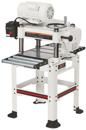
Деревообрабатывающий рейсмусовый станок JWP-12 предназначен для строгания заготовок из древесины в предварительно заданные размеры. Станок JWP-12 предназначен для индивидуальной эксплуатации и не рассчитан на работу при непрерывном производстве.
Обладая высокой производительностью, станок JWP-12 весит 27 кг и остается мобильным: его можно взять на стройку или в одиночку перемещать по мастерской. Предусмотрена установка на пол (открытая подставка входит в стандартную комплектацию) или на верстак. При эксплуатации станка следует учитывать, что точная и безотказная работа возможна только при качественном стружкоудалении, например, с помощью вытяжных установок Jet.
На станках JWP-12 не допускается обработка металлов, асбоцементных материалов, камня и подобных материалов, мягких пластмассовых и резиноподобных материалов.
Легкий и компактный рейсмусовый станок Jet JWP-12 предназначен для индивидуального использования в столярных мастерских и «на выезде» в условиях стройки. Благодаря коллекторному мотору он весит всего 30 кг, обладая при этом мощностью 1,8 кВт. Двигатели этого типа требовательны к соблюдению температурного режима, поэтому JWP-12 оснащен датчиком перегрева, отключающим питание, когда нужен перерыв на охлаждение.
По качеству строгания станок JWP-12 не уступает стационарным моделям начального уровня, напротив, высокая скорость вращения ножевого вала делает его в ряде случаев более предпочтительным. Есть все стандартные системы, характерные и для стационарных аналогов: механизм автоподачи, подающий и разгрузочный столы с роликами (для удобства транспортировки и хранения они сделаны складными), ролики сверху корпуса для обратной подачи заготовки. Регулировку высоты ножевого вала, в зависимости от размера детали, производят единственной вращающейся рукояткой.
Накопленный опыт эксплуатации JWP-12 показал, что при соблюдении всего нескольких простых правил станок очень долговечен и надежен. Требуется лишь избегать работы без подключения к пылеотсосу и вовремя прочищать все механизмы от стружки.
Важное достоинство строгальных станков Jet на фоне аналогов других марок – надежное снабжение расходными материалами, в частности сменными ножами, причем модель JWP-12 изначально поставляется с запасным комплектом качественных лезвий из быстрорежущей стали.
Конструктивные особенности рейсмуса JWP-12
- Высокая скорость вращения ножевого вала обеспечивает качественную поверхность после обработки
- Для регулировки высоты строгания поднимается и опускается строгальный узел, содержащий электродвигатель, ножевой вал и подающие валы
- Регулировка высоты строгания вращающейся рукояткой
- Наличие системы отключения двигателя при перегрузке
- Наличие откидных роликовых подающего и разгрузочного столов
Станок работает от однофазной сети переменного тока напряжением 220 В частотой 50 Гц.
Станок может эксплуатироваться в нормальных климатических условиях:
- температура окружающей среды от 1 до 35 °C
- относительная влажность воздуха до 80 % при температуре 25 °C
Источник
Устройство и принцип работы рейсмусового станка jet jwp 12
 Выпускается рейсмусовый станок Jet JWP-12 швейцарским предприятием JPW Tools A. G., которое представляет собой дочернее подразделение акционерного общества Walter Meier A. G. (Tool). В России продажа продукции организована фирмой ИТА-СПБ в г. Санкт-Петербурге, которая также является дочерней компанией, наделенной правами по распространению, продвижению и обслуживанию станков швейцарских изготовителей.
Рейсмусовый электрический переносной станок Jet JWP-12
По качеству работы деревообрабатывающий строгальный станок не уступает моделям стационарного типа, высокоскоростное вращение рабочего вала предпочтительнее в некоторых случаях. Присутствуют все устройства, привычные для стационарных агрегатов:
- разгрузочный и подающий столы со встроенными роликами, для удобства хранения и перевозки с места на место они сконструированы в складном варианте;
- механизм автоматической подачи обрабатываемого материала;
- сверху корпуса предусмотрены ролики для обратного движения заготовки;
- оборачиваемая рукоять предназначена для установки на нужной высоте ножевого вала.
Назначение агрегата и область применения
 Деревообрабатывающий станок предназначен для обработки деревянных заготовок строганием в заранее определенные размеры. Станок рассчитан на мелкосерийное производство и индивидуальное использование, а для непрерывного производственного процесса не подходит.
Мобильность станка обеспечивается небольшим весом (27 кг), поэтому легко переставляется на новое рабочее место в условиях цеха или перевозится на другую стройку или в мастерскую. При работе предусмотрена установка на пол или на верстак, для этого к комплектации продается дополнительно открытая подставка.
Эксплуатация станка в экономном и безотказном режиме происходит в случае подключения к станку вытяжной установки марки Jet с целью постоянного удаления стружки и мелкой древесной пыли. Нельзя обрабатывать на рейсмусовом станке каменные заготовки, металлические, асбоцементные и из других материалов. Строгание мягких резиноподобных и пластмассовых деталей также недопустимо.
Несмотря на компактные размеры и небольшую массу, рейсмус Jet JWP-12 отличается мощностью 1,8 кВт. Этого достаточно для строгания доски на строительных площадках или в мастерских. Двигатель станка реагирует на температурные перепады, поэтому есть датчик перегрева, отключающий подачу энергии при перегрузке и регулирующий период охлаждения агрегата.
Надежность и долговечность свойственна всей продукции, выпускаемой этим предприятием. Для правильной работы без сбоев и ремонтов следует выполнять простые правила:
- регулярно очищать все видимые механизмы от стружки;
- избегать строгания без использования пылеотсоса.
Важным в выборе именно этой модели на рынке деревообрабатывающего оборудования является надежное снабжение фирменными запасными частями и расходными материалами, например, сменными ножами. В комплектации станка изначально продаются запасные лезвия из качественной быстрорежущей стали.
Конструкция рейсмуса
 В процессе проектирования и в производстве используется стандартный способ компоновки узлов и деталей, не забыли конструкторы учесть и условия работы в маленьких помещениях. В конструкции нет устройства, защищающего станок от дождя и другой влаги в атмосфере. В качестве основы применена металлическая рама, укрепленная с помощью дополнительных ребер жесткости, на которой крепятся все остальные рабочие элементы станка.
Описание компонентов оборудования
Все комплектующие узлы имеют индивидуальные функции в целом обеспечивая надежную и безопасную работу:
- Блок обработки находится верхней части конструкции и представляет собой комплект из подающих роликов. Чтобы обезопасить процесс подачи в станке есть фиксирующие когти для устранения возможности обратного хода заготовки.
- Работа привода происходит за счет действия силовой установки, расположенной в блоке обработки. На передней панели корпуса имеются кнопки управления, предусмотрено отключающее реле для остановки при перегрузке.
- Рабочие столы состоят в комплекте из поверхности для приема и подачи. Эти детали не предназначены для подъема и опускания, так как толщина строгального слоя регулируется высотой блока обработки (строгальный узел с электродвигателем, подающие валы и ножевой вал).
- Подъемный механизм имеет значение при выборе заглубления при обработке. Положение ножевого вала меняется ручкой сверху корпуса. На передней части корпуса располагается рабочая шкала для отслеживания текущего расположения обработочного блока.
Условия для работы станка:
- переменный ток в однофазной сети частотой 50 Гц и напряжением 220 В;
- влажность воздуха (относительная) не выше 80%;
- температура окружающей атмосферы от 0˚С до 25−30˚С.
Комплектация станка
При покупке оборудования вместе с рейсмусом Jet 12 продаются следующие приспособления:
 патрубок для подключения вытяжки пыли и стружки;
- рукоять для выбора высоты;
- шаблон, используемый при установке (замене) ножей на валу;
- ножки под корпус резиновые — 4 шт.;
- инструменты для монтажа станка;
- инструкция по эксплуатации.
 патрубок для подключения вытяжки пыли и стружки;
На корпусе имеются детали:
- общий выключатель;
- транспортировочные ролики;
- выключатель, срабатывающий при перегреве;
- рукоятка для установки требуемой высоты;
- щетки электродвигателя;
- отверстия, используемые при переноске агрегата;
- отверстия для крепления откидывающихся частей стола;
- измерительно-контрольная шкала;
- подающие ролики.
Установление строгальных ножей на станок
Для станка используют лезвия, подходящие по EN 847−1 и технические требования. Если ножи затупились, в процессе работы ослабилось крепление или лезвия изначально были установлены неправильно, то опасность травм значительно повышается. Менять нужно одновременно два ножа, как и подтачивать их вместе по одинаковой технологии.
Планки, прижимающие лезвия, устанавливаются с любой из сторон, так как сбалансированы по отношению один к другому. Дополнительная шлифовка делается только на лезвиях с надписью HSS или HS и она выполняется одинаково для обоих экземпляров, так как разбалансировка выводит из строя подшипники. Шлифовка ведется только до ширины ножей 14 мм.
Если требуется замена запасных частей, то используют только фирменные детали JET. При замене ножа устанавливают прижимную планку лезвия в паз на ножевом валу. Проверяют нахождение в привычном месте пружин. Четырехгранные болты вкручивают так, чтобы можно было вставить лезвие. Вставляют нож и регулируют прижимную пластину, чтоб она не показывалась за ножевым валом. Для регулировки высоты расположения ножа используют стандартный ножевой шаблон.
Основные технические характеристики станка JWP-12
Все станки этой марки имеют стандартные технические показатели:
- толщина обрабатываемых деревянных заготовок находится в пределах 6−154 мм;
- наибольшая ширина полосы строгания — 318 мм;
- наибольшая величина заглубления при строгании — 2,5 мм;
- скорость передвижения детали — 7 м в минуту;
- самая малая допустимая длина детали — 255 мм;
- частота оборотов — 9 тыс. в минуту;
- число ножей на валу — 2 шт.;
- длина, толщина и ширина рабочего лезвия — 318x3x18 мм (соответственно);
- строгальный вал имеет диаметр 48 мм;
- общая длина с дополнениями рейсмусового стола — 296 (695) мм;
- на станке 1 электрический двигатель коллекторного типа;
- рабочий ток — 8 А;
- предохранитель плавкий — 16 А;
- провод для соединения 3×1 мм;
- габарит агрегата — 580×560×463 мм (длина, ширина, высота, соответственно).
 наибольшая величина заглубления при строгании — 2,5 мм;
Общие указания по работе
Обработка других материалов, кроме древесины, может быть разрешена только после консультации с представителем компании. При эксплуатации выполняют все требования:
- техники безопасности;
- предписаний производителя;
- общие указания и технические правила эксплуатации деревообрабатывающего оборудования.
Любое отклонение от пунктов указанных требований рассматривается производителем как неправильное использование, и ответственность за повреждения несет покупатель. В агрегате нельзя изменять конструкцию и вносить технические усовершенствования, использовать оборудование можно только в исправном состоянии. Отвечает за работу в части соблюдения правил покупатель и пользователь.
Обязательно устанавливаются защитные крышки и приспособления. Соединительный кабель от защитного автомата и источника до станка по длине должен быть не менее 3 метров сечением 1,5×3 (медный трехжильный, с сечением жилы не менее 1,5). Работать на станке имеют право люди, ознакомленные с принципами его работы, способами технического обслуживания и прослушавшие инструкцию по технике безопасности.
Требования техники безопасности при работе
Указания по безопасной работе включают инструкцию по правильной эксплуатации и регулярное обследование технического состояния с исправлением отклонений:
- каждый день перед включением станка проверяют сохранность всех защитных устройств, их функциональность;
- если выявлены дефекты или неисправности станка, их исправлением занимаются специалисты, самостоятельно приступать к ремонту не рекомендуется, нужно только отключить станок от электрического питания;
- при работе нужно надевать средства индивидуальной защиты (облегающую одежду, очки, специальные перчатки);
- в рабочей зоне станка не должны находиться посторонние, дети;
- перед строганием досок, бывших в употреблении, их осматривают с целью выявления и удаления гвоздей, шурупов, металлических скоб;
- следует соблюдать минимальные и максимальные допуски по длине для заготовок, короткие детали нельзя строгать, так как их удерживание составляет трудность, их может вырвать из станка и травмировать человека;
- строгание длинных заготовок производят только с использованием дополнительных столов, на весу держать доски нельзя, в работе при подаче заготовки используют обе руки;
- удалять стружку из станка вручную можно только при выключенном электрическом питании, перед уходом с рабочего места обязательно выключают агрегат;
- станок перед работой проверяют на устойчивость, для этого у станка должно быть крепкое основание, а вокруг достаточно места для разворота досок;
- зона работы должна иметь хорошее освещение;
- поблизости легковоспламеняющихся предметов и жидкостей ставить станок нельзя, при малейшем возгорании вызывают службу пожарных;
- нельзя работать во время дождя на открытой территории без навеса или в слишком влажных помещениях;
- следят за накоплением пыли, вовремя удаляют ее, так как древесная пыль относится к взрывоопасным категориям и вредна для дыхательных путей человека;
- к электрическому обслуживанию допускаются только квалифицированные электрики;
- мощность станка используется в указанных пределах, оборудование работает дольше, если его не перегружают.
 каждый день перед включением станка проверяют сохранность всех защитных устройств, их функциональность;
Опасности при работе
Опасные ситуации могут возникнуть даже при правильном использовании станка. От вращающегося ножа в рабочей зоне можно получить травму кисти, если строгальные ножи разрушаются из-за неправильной установки или разбалансировки. Помимо этого, присутствие в досках метизов или крепких сучков способствует созданию неучтенного усилия, и заготовка вырывается из станка.
 Для работы пользуются наушниками, так как повышенный шум ухудшает слух и может стать причиной других серьезных заболеваний. Кабель располагают так, чтобы он не находился в зоне прохода и не был зацеплен передвигающейся заготовкой, при его разрыве вызывают специалистов.
Перед началом работы в новом месте проверяют соответствие параметров сети техническим требованиям по эксплуатации станка, написанным на табличке корпуса, а именно частоту электрического тока и напряжение. Защитное устройство работает при силе тока в 16 А, обязательно подключают вытяжку пыли через соответствующий патрубок агрегата.
Источник