
-
Contents
-
Table of Contents
-
Troubleshooting
-
Bookmarks
Quick Links
Operation Manual
615 series
Related Manuals for ABB REF615
Summary of Contents for ABB REF615
-
Page 1
Operation Manual 615 series… -
Page 3
Document ID: 1MRS756708 Issued: 04.03.2009 Revision: A Product version: 2.0 © Copyright 2009 ABB. All rights reserved… -
Page 4
Copyright This document and parts thereof must not be reproduced or copied without written permission from ABB, and the contents thereof must not be imparted to a third party, nor used for any unauthorized purpose. The software or hardware described in this document is furnished under a license and may be used, copied, or disclosed only in accordance with the terms of such license. -
Page 5
In case any errors are detected, the reader is kindly requested to notify the manufacturer. Other than under explicit contractual commitments, in no event shall ABB be responsible or liable for any loss or damage resulting from the use of this manual or the application of the equipment. -
Page 6
(Low-voltage directive 2006/95/ EC). This conformity is the result of a test conducted by ABB in accordance with Article 10 of the directive in agreement with the product standards EN 50263 and EN 60255-26 for the EMC directive, and with the product standards EN 60255-6 and EN 60255-27 for the low voltage directive. -
Page 7: Safety Information
Safety information Dangerous voltages can occur on the connectors, even though the auxiliary voltage has been disconnected. Non-observance can result in death, personal injury or substantial property damage. Only a competent electrician is allowed to carry out the electrical installation. National and local electrical safety regulations must always be followed.
-
Page 9: Table Of Contents
Table of contents Table of contents Section 1 Introduction……………7 This manual………………7 Intended audience…………….7 Product documentation……………8 Product documentation set…………8 Document revision history………….9 Related documentation…………..9 Document symbols and conventions……….10 Safety indication symbols…………10 Document conventions…………..10 Functions, codes and symbols…………11 Section 2 Environmental aspects………..13 Sustainable development…………..13 Disposing of the IED……………..13 Section 3 615 series overview…………15…
-
Page 10
Table of contents Identifying the device…………..32 Adjusting display contrast…………33 Changing LHMI language…………33 Changing display symbols…………34 Navigating in the menu…………..34 Menu structure……………35 Scrolling the LCD view…………35 Changing the default view…………36 Browsing setting values……………36 Editing values…………….36 Editing numerical values…………37 Editing string values……………38 Editing enumerated values………….38 Committing settings…………..39 Clearing and acknowledging…………40… -
Page 11
Table of contents IED settings for IED functionality……….65 IED settings for different operating conditions……66 Section 6 Operating procedures………….67 Monitoring………………67 Indications……………….67 Monitoring indication messages……….67 Monitoring an internal IED fault ……….68 Monitoring condition monitoring data……..68 Measured and calculated values……….68 Measured values…………..68 Using LHMI for monitoring…………69 Recorded data…………….69 Creating disturbance recordings……….70 Monitoring disturbance recorder data……..70… -
Page 12
Table of contents Correction procedures…………..86 Rebooting software…………..86 Restoring factory settings…………86 Setting password……………..86 Identifying IED application problems………..87 Inspecting wiring…………..87 Sample data interruptions…………87 Section 8 Commissioning……………89 Commissioning checklist…………..89 Checking installation……………..89 Checking the power supply…………89 Checking CT circuits…………..90 Checking VT circuits…………..90 Checking binary input and output circuits……..91 Binary input circuits…………..91 Binary output circuits…………..91 Authorizations……………….91… -
Page 13
Table of contents Testing digital I/O interface…………110 Testing functions……………111 Selecting internal fault test…………111 ABB Product Data Registration…………112 Section 9 Glossary……………113 615 series Operation Manual… -
Page 15: Section 1 Introduction
Section 1 1MRS756708 A Introduction Section 1 Introduction This manual Operation Manual contains instructions on how to operate the IED during normal service once it has been commissioned. The manual can be used to find out how to handle disturbances or how to view calculated and measured network data to determine the cause of a fault.
-
Page 16: Product Documentation
Section 1 1MRS756708 A Introduction Product documentation 1.3.1 Product documentation set Engineering manual Engineering manual Engineering manual Installation manual Installation manual Installation manual Commissioning manual Commissioning manual Commissioning manual Operation manual Operation manual Operation manual Service manual Service manual Service manual Application manual Application manual Application manual…
-
Page 17: Document Revision History
Document revision history Document revision/date Product series version History A/04.03.2009 First release Download the latest revision of the document from the ABB web site http://www.abb.com/substationautomation. 1.3.3 Related documentation Product series- and product-specific manuals can be downloaded from the ABB web site http://www.abb.com/substationautomation…
-
Page 18: Document Symbols And Conventions
Section 1 1MRS756708 A Introduction Document symbols and conventions 1.4.1 Safety indication symbols This publication includes icons that point out safety-related conditions or other important information. The electrical warning icon indicates the presence of a hazard which could result in electrical shock. The warning icon indicates the presence of a hazard which could result in personal injury.
-
Page 19: Functions, Codes And Symbols
Section 1 1MRS756708 A Introduction • LHMI messages are shown in Courier font, for example: To save the changes in non-volatile memory, select Yes and press • Parameter names are shown in italics, for example: The function can be enabled and disabled with the Operation setting. •…
-
Page 20
Section 1 1MRS756708 A Introduction Function IEC 61850 IEC 60617 IEC-ANSI Residual overvoltage protection ROVPTOV1 > (1) 59G (1) ROVPTOV2 > (2) 59G (2) ROVPTOV3 > (3) 59G (3) Three-phase undervoltage protection PHPTUV1 3U< (1) 27 (1) PHPTUV2 3U< (2) 27 (2) PHPTUV3 3U<… -
Page 21: Section 2 Environmental Aspects
Section 2 1MRS756708 A Environmental aspects Section 2 Environmental aspects Sustainable development Sustainability has been taken into account from the beginning of the product design including the pro-environmental manufacturing process, long life time, operation reliability and disposing of the IED. The choice of materials and the suppliers has been made according to the EU RoHS directive (2002/95/EC).
-
Page 22
Section 2 1MRS756708 A Environmental aspects electrical/electronics waste. These partners can sort the material by using dedicated sorting processes and dispose of the product according to the local requirements. Table 3: Materials of the IED parts Parts Material Case Metallic plates, parts and screws Steel Plastic parts , LCP… -
Page 23: Section 3 615 Series Overview
Section 3 1MRS756708 A 615 series overview Section 3 615 series overview Overview 615 series is a product family of intelligent devices designed for protection, control, measurement and supervision of utility substations and industrial switchgear and equipment. The design of the IEDs has been guided by the IEC 61850 standard for communication and interoperability of substation automation devices.
-
Page 24: Lhmi
Section 3 1MRS756708 A 615 series overview LHMI A070704 V2 EN Figure 1: LHMI The LHMI of the IED contains the following elements: • Display • Buttons • LED indicators • Communication port The LHMI is used for setting, monitoring and controlling. 3.2.1 The LHMI includes a graphical LCD that supports two character sizes.
-
Page 25
Section 3 1MRS756708 A 615 series overview Character size Rows in view Characters on row Small, mono-spaced (6×12 5 rows pixels) 10 rows with large screen Large, variable width (13×14 4 rows min 8 pixels) 8 rows with large screen The display view is divided into four basic areas: A070705 V2 EN Figure 2:… -
Page 26: Leds
Section 3 1MRS756708 A 615 series overview The display is updated either cyclically or based on changes in the source data such as parameters or events. 3.2.2 LEDs The LHMI includes three protection indicators above the display: Ready, Start and Trip.
-
Page 27
Section 3 1MRS756708 A 615 series overview 11 Right 12 Key 13 Remote/Local 14 Menu 15 Help 16 Communication port Object control If the control position of the IED is set to local with the R/L button, the IED can be controlled using the object control buttons. -
Page 28
Section 3 1MRS756708 A 615 series overview Table 5: Navigation push-buttons Name Description • Leaving setting mode without saving the values. • Cancelling certain actions. • Adjusting the display contrast in combination with • Changing the language in combination with •… -
Page 29: Lhmi Functionality
Section 3 1MRS756708 A 615 series overview 3.2.4 LHMI functionality 3.2.4.1 Protection and alarm indication Protection indicators Protection indicator LEDs are Ready, Start and Trip. Table 7: Ready LED LED state Description Auxiliary supply voltage is disconnected. Normal operation. Flashing Internal fault has occurred or the IED is in test mode.
-
Page 30: Parameter Management
Section 3 1MRS756708 A 615 series overview Table 10: Alarm indications LED state Description Normal operation. All alarms are OFF. • Non-latched mode: alarm is still on. • Latched mode: alarm is still on or it is off but has not been acknowledged.
-
Page 31: Whmi
Section 3 1MRS756708 A 615 series overview When a computer is connected to the IED, the IED’s DHCP server for the front interface assigns an IP address to the computer. The fixed IP address for the front port is 192.168.0.254. WHMI The WHMI enables the user to access the IED via a web browser.
-
Page 32: Command Buttons
Section 3 1MRS756708 A 615 series overview A070754 V3 EN Figure 5: Example view of the WHMI The WHMI can be accessed: • Locally by connecting your laptop to the IED via the front communication port. • Remotely over LAN/WAN. 3.3.1 Command buttons Command buttons can be used to edit parameters and control information via the…
-
Page 33: Authorization
Section 3 1MRS756708 A 615 series overview Name Description Rejecting changes. Showing context sensitive help messages. Clearing events. Triggering the disturbance recorder manually. Saving values to CSV file format. Freezing the values so that updates are not displayed. Receiving continuous updates to the monitoring view. Deleting the disturbance record.
-
Page 34: Communication
Section 3 1MRS756708 A 615 series overview Table 12: Predefined user categories Username User rights VIEWER Read only access OPERATOR • Selecting remote or local state with (only locally) • Changing setting groups • Controlling • Clearing alarm and indication LEDs and textual indications ENGINEER •…
-
Page 35: Pcm600 Configuration Tool
Section 3 1MRS756708 A 615 series overview optic LC connector (100BASE-FX). An optional serial interface is available for RS-232/RS-485 communication. PCM600 configuration tool Protection and Control IED Manager PCM600 offers all the necessary functionality to work throughout all stages of the IED life cycle: •…
-
Page 36: Pcm600 And Ied Connectivity Package Version
PCM600 and IED connectivity package version Supported tools: • Protection and Control IED Manager PCM600 Ver. 2.0 SP2 or later • Depending on the product, either REF615 Connectivity Package Ver. 2.0 or RED615 Connectivity Package Ver. 1.0 • Parameter Setting Tool •…
-
Page 37: Section 4 Using Hmi Locally Or Via Web Interface
Section 4 1MRS756708 A Using HMI locally or via web interface Section 4 Using HMI locally or via web interface Using LHMI You must be logged in and authorized to use the LHMI. Password authorization is disabled by default and can be enabled either via the LHMI or WHMI. To enable password authorization, select Main Menu/ Configuration/Authorization/Local override.
-
Page 38: Logging Out
Section 4 1MRS756708 A Using HMI locally or via web interface A070890 V2 EN Figure 7: Entering password Press to confirm the login. • To cancel the procedure, press A070889 V2 EN Figure 8: Error message indicating wrong password The current user level is shown on the LCD’s upper right corner in the icon area.
-
Page 39: Turning Display Backlight On
Section 4 1MRS756708 A Using HMI locally or via web interface A070837 V3 EN Figure 9: Logging out • To cancel logout, press 4.1.3 Turning display backlight on The display backlight is normally off. It turns on during the display test at power up. •…
-
Page 40: Identifying The Device
Section 4 1MRS756708 A Using HMI locally or via web interface The control position cannot be simultaneously local and remote, but it can be disabled when neither of the positions is active. You must be logged in and authorized to control the IED. 4.1.5 Identifying the device The IED information includes detailed information about the device, such as revision…
-
Page 41: Adjusting Display Contrast
Section 4 1MRS756708 A Using HMI locally or via web interface A071160 V2 EN Figure 11: IED information 4.1.6 Adjusting display contrast Adjust the display contrast anywhere in the menu structure to obtain optimal readability. • To increase the contrast, press simultaneously •…
-
Page 42: Changing Display Symbols
Section 4 1MRS756708 A Using HMI locally or via web interface A071010 V2 EN Figure 12: Changing the LHMI language To change the language using a shortcut, press simultaneously. 4.1.8 Changing display symbols To switch between the display symbols IEC 61850, IEC 60617 and IEC-ANSI: Select Main Menu/Configuration/HMI/FB naming convention and press Change the display symbols with Press…
-
Page 43: Menu Structure
Section 4 1MRS756708 A Using HMI locally or via web interface 4.1.9.1 Menu structure The Main menu contains main groups which are divided further into more detailed submenus. • Events • Measurements • Disturbance records • Settings • Configuration • Monitoring •…
-
Page 44: Changing The Default View
Section 4 1MRS756708 A Using HMI locally or via web interface 4.1.9.3 Changing the default view The default view of the display is Measurements unless set otherwise. Select Main menu/Configuration/HMI/Default view and press Change the default view with Press to confirm the selection. 4.1.10 Browsing setting values Select Main Menu/Settings/Settings and press…
-
Page 45: Editing Numerical Values
Section 4 1MRS756708 A Using HMI locally or via web interface 4.1.11.1 Editing numerical values Select Main menu/Settings and then a setting. When you start editing numerical values, the last digit is active. • When the symbol in front of the value is ↑, you can only increase the active value.
-
Page 46: Editing String Values
Section 4 1MRS756708 A Using HMI locally or via web interface A070756 V2 EN Figure 17: Arrow symbol is active, the value is set to the maximum After pressing , the previous value can be restored by pressing once, and vice versa.
-
Page 47: Committing Settings
Section 4 1MRS756708 A Using HMI locally or via web interface One press changes the enumerated value by one step in the parameter specific order. 4.1.12 Committing settings Editable values are stored either in RAM or in non-volatile flash memory. Values stored in flash memory are in effect also after reboot.
-
Page 48: Clearing And Acknowledging
Section 4 1MRS756708 A Using HMI locally or via web interface 4.1.13 Clearing and acknowledging The Clear button is used to reset, acknowledge or clear all messages and indications, including LEDs and latched outputs as well as registers and recordings. Press the Clear button to activate a selection menu, where you can choose which clearance or reset function you want to make.
-
Page 49: Using Whmi
Section 4 1MRS756708 A Using HMI locally or via web interface Using WHMI WHMI is disabled by default. You must be logged in and authorized to use the WHMI. To enable the WHMI, select Main menu/Configuration/HMI/Web HMI mode via the LHMI. Reboot the IED for the change to take effect.
-
Page 50: Identifying The Device
Section 4 1MRS756708 A Using HMI locally or via web interface A070924 V3 EN Figure 22: WHMI logout 4.2.3 Identifying the device The IED information includes detailed information about the device, such as revision and serial number. Click Information in the WHMI menu structure. Click a submenu to see the data.
-
Page 51: Navigating In The Menu
Section 4 1MRS756708 A Using HMI locally or via web interface A070925 V3 EN Figure 23: Device information 4.2.4 Navigating in the menu The menu tree structure on the WHMI is identical to the one on the LHMI. Use the menu bar to access different views.
-
Page 52: Menu Structure
Section 4 1MRS756708 A Using HMI locally or via web interface A070945 V3 EN Figure 24: Navigating in the WHMI menus 4.2.4.1 Menu structure The Main menu contains main groups which are divided further into more detailed submenus. • Events •…
-
Page 53
Section 4 1MRS756708 A Using HMI locally or via web interface A070963 V3 EN Figure 25: Show all parameters Click Print to print out all parameters on paper. 615 series Operation Manual… -
Page 54: Editing Values
Section 4 1MRS756708 A Using HMI locally or via web interface A071008 V3 EN Figure 26: All parameters listed Click Save to save all parameters in CSV file format. 4.2.6 Editing values Click the menu in the WHMI tree. Click the submenu to see function blocks. Click a function block to see the setting values.
-
Page 55
Section 4 1MRS756708 A Using HMI locally or via web interface A070929 V3 EN Figure 27: Enable writing to edit a value The selected setting group is shown in the Setting Group drop-down box. The active setting group is indicated with an asterisk *. Edit the value. -
Page 56: Committing Settings
Section 4 1MRS756708 A Using HMI locally or via web interface A070934 V2 EN Figure 29: Warning indicating that the entered value is incorrect • If writing values fails, a warning dialog box is displayed. GUID-E10EE091-CFB9-4278-9FA4-7340C26F5814 V1 EN Figure 30: Warning indicating that the values were not written to the If you accidentally click Enable Write, click Disable Write.
-
Page 57
Section 4 1MRS756708 A Using HMI locally or via web interface A070931 V3 EN Figure 31: Writing values to IED The values are not stored to the flash memory. Click Commit to write the values to the flash memory. • Click Reject to cancel saving settings. -
Page 58: Clearing And Acknowledging
Section 4 1MRS756708 A Using HMI locally or via web interface Committing values will take a few seconds. If you only write values to the IED and then reboot, the old values will resume in the IED as active values and the new values are lost. 4.2.8 Clearing and acknowledging Reset, acknowledge or clear all messages and indications, including LEDs and latched…
-
Page 59: Selecting Alarm View
Section 4 1MRS756708 A Using HMI locally or via web interface A070936 V3 EN Figure 34: Clearing indications and LEDs 4.2.9 Selecting alarm view Alarm view shows the status of alarm LEDs. These are the same LEDs that are located on the upper right side of the LHMI panel.
-
Page 60: Selecting Event View
Section 4 1MRS756708 A Using HMI locally or via web interface A070946 V3 EN Figure 35: Monitoring alarms 4.2.10 Selecting event view The event view contains a list of events produced by the application configuration. Click Events in the menu bar. 615 series Operation Manual…
-
Page 61: Selecting The Disturbance Record View
Section 4 1MRS756708 A Using HMI locally or via web interface A070947 V3 EN Figure 36: Monitoring events Click Save to save the events in CSV file format. The CSV file can be opened with a spreadsheet program such as OpenOffice.org Calc or Microsoft Excel.
-
Page 62: Uploading Disturbance Records
Section 4 1MRS756708 A Using HMI locally or via web interface GUID-2B46A09D-730E-45D3-BE30-20546BB6F8AD V1 EN 4.2.11.1 Uploading disturbance records Click Disturbance records on the menu bar. To upload a disturbance record, click the icons in the CFG and DAT columns of the record. 615 series Operation Manual…
-
Page 63: Triggering The Disturbance Recorder Manually
Section 4 1MRS756708 A Using HMI locally or via web interface GUID-0280828D-0DFF-4C83-90A0-D8E57E17E51A V1 EN Save both the files in the same folder on your computer, and open the disturbance record files with a suitable program. 4.2.11.2 Triggering the disturbance recorder manually Click Disturbance records on the menu bar.
-
Page 64: Deleting Disturbance Records
Section 4 1MRS756708 A Using HMI locally or via web interface GUID-4F5661CB-2317-4F4C-9DA2-BFADFA71BA3E V1 EN Figure 37: Manual triggering 4.2.11.3 Deleting disturbance records Click Disturbance records on the menu bar. Delete records. • Click Delete all to delete all records. • Select one or more recordings and click Delete to delete selected records.
-
Page 65: Selecting Phasor Diagrams
Section 4 1MRS756708 A Using HMI locally or via web interface GUID-E109C24F-8CC9-4074-A175-DA4820BA7913 V1 EN Figure 38: Deleting disturbance records Click OK to confirm or Cancel to cancel the deletion. 4.2.12 Selecting phasor diagrams Click Phasor diagrams in the menu bar. 615 series Operation Manual…
-
Page 66
Section 4 1MRS756708 A Using HMI locally or via web interface A070948 V3 EN Figure 39: Monitoring phasors Toggle the diagram visibility by selecting it from the drop-down menu. 615 series Operation Manual… -
Page 67
Section 4 1MRS756708 A Using HMI locally or via web interface GUID-5F3C9CC8-1AE8-4235-836F-AC93E1E73708 V2 EN Figure 40: Toggling the diagram visibility Visible diagrams are indicated with an asterisk *. Change the size of the diagram by changing the zoom value. 615 series Operation Manual… -
Page 68
Section 4 1MRS756708 A Using HMI locally or via web interface GUID-690A11A9-FEC4-4558-A68F-16FBAC500E3B V2 EN Figure 41: Zooming the diagram Click Freeze to stop updating the phasor diagram. No updates are displayed in the diagram. 615 series Operation Manual… -
Page 69: Selecting Disturbance Records
Section 4 1MRS756708 A Using HMI locally or via web interface A071226 V3 EN Figure 42: The arrow extends outside the circle if the current value is too high Install an SVG plugin to view the phasor diagrams. 4.2.13 Selecting disturbance records Click Disturbance records in the menu bar.
-
Page 70
Section 4 1MRS756708 A Using HMI locally or via web interface A070927 V3 EN Figure 43: Clicking the help button To close the help dialog box, click OK. 615 series Operation Manual… -
Page 71: Section 5 Ied Operation
Section 5 1MRS756708 A IED operation Section 5 IED operation Normal operation The basic operation procedures in normal IED use situation are: • Monitoring measured values • Checking object states • Checking function setting parameters • Checking events and alarms All basic operations can be performed via the LHMI, WHMI or with PCM600.
-
Page 72: Disturbance Recording Triggering
Section 5 1MRS756708 A IED operation Document the disturbance before clearing the information from the IED. Only authorized and skilled personnel should analyze possible errors and decide on further actions. Otherwise, stored disturbance data can be lost. 5.2.1 Disturbance recording triggering Disturbance recordings are normally triggered by IED applications when they detect fault events.
-
Page 73: Ied Parametrization
Section 5 1MRS756708 A IED operation Only authorized and skilled personnel should analyze the errors and decide on further actions. The IED records: • IED status data • Events • System registrations Document all the recorded data from the IED before you reset the tripping and IED lockout functions.
-
Page 74: Ied Settings For Different Operating Conditions
Section 5 1MRS756708 A IED operation 5.3.2 IED settings for different operating conditions IED settings can be designed for various operation conditions by defining different setting values to different setting groups. The active setting group can be changed by the IED application or manually via the LHMI. 615 series Operation Manual…
-
Page 75: Section 6 Operating Procedures
Section 6 1MRS756708 A Operating procedures Section 6 Operating procedures Monitoring 6.1.1 Indications The operation of the IED can be monitored via three different indications on the LHMI. • Three indicator LEDs with fixed functionality: Ready, Start and Trip • 11 programmable alarm LEDs •…
-
Page 76: Monitoring An Internal Ied Fault
Section 6 1MRS756708 A Operating procedures 6.1.1.2 Monitoring an internal IED fault The flashing green LED indicates an internal IED fault. Internal IED fault messages are shown in a dialog box. A071144 V2 EN Figure 45: Fault indication Select Main menu/Monitoring/IED status/Self-supervision to monitor the latest fault indication.
-
Page 77: Using Lhmi For Monitoring
Section 6 1MRS756708 A Operating procedures Table 14: Measured values Indicator Description IL1-A Current measured on phase L1 IL2-A Current measured on phase L2 IL3-A Current measured on phase L3 Measured earth-fault current Measured residual voltage U12-kV Measured phase-to-phase voltage U12 U23-kV Measured phase-to-phase voltage U23 U31-kV…
-
Page 78: Creating Disturbance Recordings
Section 6 1MRS756708 A Operating procedures 6.1.3.1 Creating disturbance recordings Normally disturbance recordings are triggered by the IED applications but the recording can also be triggered manually. Select Main menu/Disturbance records. Select Trig recording with Press , change the value with and press again.
-
Page 79: Controlling And Uploading Disturbance Recorder Data
Section 6 1MRS756708 A Operating procedures A070863 V2 EN Figure 47: Monitoring disturbance recorder via the LHMI 6.1.3.3 Controlling and uploading disturbance recorder data Disturbance recorder data can be controlled and read with PCM600. It can also be uploaded via WHMI. For more information, see PCM600 documentation.
-
Page 80: Monitoring Events
Section 6 1MRS756708 A Operating procedures 6.1.3.5 Monitoring events Event view contains a list of events produced by the application configuration. Each event takes one view area. The header area shows the currently viewed event index and the total amount of the events. The most recent event is always first. Select Main Menu/Events.
-
Page 81: Controlling
Section 6 1MRS756708 A Operating procedures Controlling 6.2.1 Controlling circuit breakers and disconnectors The primary equipment can be controlled via the LHMI with the Open and Close buttons when the IED is set to local control mode and you are authorized to access control operations.
-
Page 82: Resetting Ied
Section 6 1MRS756708 A Operating procedures The time between selecting the object and giving a control command is restricted by an adjustable time-out. When an object is selected, the control command has to be given within this time. Resetting IED 6.3.1 Clearing and acknowledging via LHMI You can reset, acknowledge or clear all messages and indications, including LEDs…
-
Page 83: Changing Ied Functionality
Section 6 1MRS756708 A Operating procedures Use the button as a shortcut for clearing. The first three-second press clears the indications. The second three-second press clears the alarm LEDs. If new indications have appeared between the first and the second press, they are cleared first. Changing IED functionality 6.4.1 Defining setting group…
-
Page 84: Copying A Setting Group
Section 6 1MRS756708 A Operating procedures A071152 V2 EN Figure 54: Selecting active setting group Commit the settings. Remember to document the changes you make. 6.4.1.2 Copying a setting group Select Main menu/Copy setting group and press Select the source and the destination with Set the group numbers with Press to confirm or…
-
Page 85: Browsing And Editing Setting Group Values
Section 6 1MRS756708 A Operating procedures A070858 V2 EN Figure 55: Selecting a setting group 6.4.1.4 Browsing and editing setting group values Select Main Menu/Settings/Settings and press Select the setting group to be viewed with and press to confirm the selection. A071166 V2 EN Figure 56: Selecting setting group…
-
Page 86
Section 6 1MRS756708 A Operating procedures A070899 V3 EN Figure 57: Setting group parameter To select a setting group value, press and to edit the value press A071168 V3 EN Figure 58: Selecting setting group value Only values within the selected setting group can be changed. Press to change the value and to confirm the selection. -
Page 87: Activating Leds
Section 6 1MRS756708 A Operating procedures 6.4.2 Activating LEDs Select Main Menu/Configuration/Alarm LEDs and press Select an Alarm LED with Press to confirm the selection and to change the Alarm LED mode. Press to change the value and to confirm the selection. For more information, see PCM600 documentation.
-
Page 89: Section 7 Troubleshooting
Inspect the IED visually • Inspect the IED visually to find the physical error causes. • If you can find some obvious physical damage, contact ABB for repair or replacement actions. Check whether the error is external or internal. •…
-
Page 90: Checking The Time Synchronization
Section 7 1MRS756708 A Troubleshooting Table 15: Communication LEDs Communication ok Uplink Steady green light Communication Flashing yellow light 7.1.3.2 Checking the time synchronization • Check the time synchronization via LHMI in Main Menu/Monitoring/IED status/Time synchronization. 7.1.4 Running the display test A short display test is always run, when auxiliary voltage is connected to the IED.
-
Page 91
Section 7 1MRS756708 A Troubleshooting A071144 V2 EN Figure 60: Fault indication Table 16: Internal fault indications and codes Fault indication Fault code Additional information Internal Fault An internal system error has occurred. System error Internal Fault A file system error has occurred. File system error Internal Fault Internal fault test activated manually by the… -
Page 92: Warnings
Section 7 1MRS756708 A Troubleshooting Fault indication Fault code Additional information Internal Fault Card in slot X130 is wrong type, is missing Conf. error,X130 or does not belong to the original composition. Internal Fault Card in slot X000 is faulty. Card error,X000 Internal Fault Card in slot X100 is faulty.
-
Page 93
Section 7 1MRS756708 A Troubleshooting A071222 V2 EN Figure 61: Warning Table 17: Warning indications and codes Warning indication Warning code Additional information Warning A watchdog reset has occurred. Watchdog reset Warning The auxiliary supply voltage has dropped Power down det. too low. -
Page 94: Led And Display Messages
Section 7 1MRS756708 A Troubleshooting Warning indication Warning code Additional information Warning A continuous light has been detected on ARC1 cont. light the ARC light input 1. Warning A continuous light has been detected on ARC2 cont. light the ARC light input 2. Warning A continuous light has been detected on ARC3 cont.
-
Page 95: Identifying Ied Application Problems
In case of permanent faults, the measurement chain shall be checked to remove the origin of the faulty measurement data. In case of persistent faults originating from IED’s internal faults, contact ABB for repair or replacement actions. 615 series Operation Manual…
-
Page 97: Section 8 Commissioning
Section 8 1MRS756708 A Commissioning Section 8 Commissioning Commissioning checklist Familiarize yourself with the IED and its functionality before you start the commissioning work. • Ensure that you have all the needed station drawings such as single line and wiring diagrams. •…
-
Page 98: Checking Ct Circuits
Section 8 1MRS756708 A Commissioning 8.2.2 Checking CT circuits The CTs must be connected in accordance with the terminal diagram provided with the IED, both with regards to phases and polarity. The following tests are recommended for every primary CT or CT core connected to the IED: •…
-
Page 99: Checking Binary Input And Output Circuits
Section 8 1MRS756708 A Commissioning Test the circuitry. The following tests are recommended: • Polarity check • VT circuit voltage measurement (primary injection test) • Earthing check • Phase relationship • Insulation resistance check The polarity check verifies the integrity of circuits and the phase relationships. The polarity should be measured as close as possible to the IED so ensure that most of the wiring is also checked.
-
Page 100: Using Pcm600
Section 8 1MRS756708 A Commissioning • Numbers 0-1 • Letters a-z, A-Z • Space • Special characters !»#%&'()*+´-./:;<=>?@[\]^_`{|}~ User authorization is disabled by default and can be enabled either via the LHMI or WHMI Main Menu/Configuration/ Authorization. Table 18: Predefined user categories Username LHMI WHMI password User rights…
-
Page 101: Communication Options
Section 8 1MRS756708 A Commissioning Set up or get the IP addresses of the IEDs. Set up the PC for a direct link or connect the PC or workstation to the network. Configure the IED IP addresses in the PCM600 project for each IED. The addresses are used for communication by the OPC interface of PCM600.
-
Page 102
Section 8 1MRS756708 A Commissioning To open Network Connections, click Start, point to Settings, click Control Panel, and then double-click Network Connections. Double-click the connection that you want to configure, and then click Properties. Select the TCP/IP protocol from the list of configured components using this connection and click Properties. -
Page 103
Section 8 1MRS756708 A Commissioning A071224 V1 EN Figure 63: Obtaining IP address automatically Close all open windows by clicking OK and start PCM600. Administrator rights are requested to change the configuration as described above. Setting rear communication To set up a standard PC with MicroSoft Windows operating system for rear communication: To open Network Connections, click Start, point to Settings, click Control Panel, and then double-click Network Connections. -
Page 104
Section 8 1MRS756708 A Commissioning A071162 V1 EN Figure 64: Selecting TCP/IP protocol Choose Use the following IP address. Enter an IP address and a subnet mask. Make sure that the IP address is unique, that is not used by any other IED on the network. -
Page 105
Section 8 1MRS756708 A Commissioning A071164 V1 EN Figure 65: Setting IP address and subnet mask Close all open windows by clicking OK and start PCM600. Administrator rights are requested to change the configuration as described above. Setting IED’s IP address in PCM600 In PCM600 the IED’s IP address can be defined either via the first window of the wizard by including a new IED in the project or by entering the IED’s IP address in the Object Properties window. -
Page 106: Setting Ied And Communication
Section 8 1MRS756708 A Commissioning Setting IED and communication 8.5.1 Communication settings The IED is provided with an RJ-45 connector on the LHMI. The connector is mainly used for configuration and setting purposes. The fixed IP address for the front port is 192.168.0.254.
-
Page 107: Serial Link Diagnostics And Monitoring
Section 8 1MRS756708 A Commissioning COM parameter Values Hardware options Serial mode 0 = RS485 2wire For galvanic modes. RS-type depends on the communication card used. 1 = RS485 4wire Note that this setting parameter is Fiber mode is set to No relevant only if 2 = RS232 no handshake Fiber .
-
Page 108
Section 8 1MRS756708 A Commissioning serial link driver. Diagnostic counters and monitoring values are found via the LHMI in Monitoring/Communication/COMn (n= 1,2,…). Depending on the communication protocol, the serial driver software receives single characters or complete protocol frames, based on the frame start/stop characters or on timing. -
Page 109
Section 8 1MRS756708 A Commissioning Table 21: Basic diagnostic counters Counter Function Characters received Counts all incoming non-erroneous characters. This counter operates regardless of if the serial driver is set to detect a whole protocol link frame or just separate characters. Frames received Counts all protocol specific non-erroneous frames received. -
Page 110: Defining Ethernet Port Settings
Section 8 1MRS756708 A Commissioning Table 23: Link status Parameter Function Link status Link status in write direction: By writing 1 to the parameter the diagnostic counters are reset to 0. Link status in monitoring direction: If the driver is in use by any communication protocol, the monitoring value shows 1.
-
Page 111: Setting Lhmi
Section 8 1MRS756708 A Commissioning 8.5.2 Setting LHMI 8.5.2.1 Changing LHMI language Select Main Menu/Language and press Change the language with Press to confirm the selection. Commit the changes. A071010 V2 EN Figure 66: Changing the LHMI language To change the language using a shortcut, press simultaneously.
-
Page 112: Changing The Default View
Section 8 1MRS756708 A Commissioning Select Main Menu/Configuration/HMI/FB naming convention and press Change the display symbols with Press to confirm the selection. The IED has to be rebooted if the WHMI display symbols are changed. With the LHMI, the change takes effect immediately. 8.5.2.4 Changing the default view The default view of the display is Measurements unless set otherwise.
-
Page 113: Setting Ied Parameters
Section 8 1MRS756708 A Commissioning Table 24: DST change on Sunday Day of the DST shift DST on/off date First Sunday of the month Second Sunday of the month Third Sunday of the month Fourth Sunday of the month Last Sunday, if the month has 30 days Last Sunday, if the month has 31 days For example, if the DST is observed from the last Sunday in March to the last Sunday in October and the time shift occurs at 01:00 UTC, the setting parameters…
-
Page 114
Section 8 1MRS756708 A Commissioning A070858 V2 EN Figure 67: Selecting a setting group Browsing and editing setting group values Select Main Menu/Settings/Settings and press Select the setting group to be viewed with and press to confirm the selection. A071166 V2 EN Figure 68: Selecting setting group To browse the settings, scroll the list with… -
Page 115
Section 8 1MRS756708 A Commissioning A070899 V3 EN Figure 69: Setting group parameter To select a setting group value, press and to edit the value press A071168 V3 EN Figure 70: Selecting setting group value Only values within the selected setting group can be changed. Press to change the value and to confirm the selection. -
Page 116: Ied Parametrization
Section 8 1MRS756708 A Commissioning Activating a setting group IED settings are planned in advance for different operation conditions by calculating setting values to different setting groups. The active setting group can be changed by the IED application or manually from the menu. Select Main Menu/Settings/Setting group/Active group and press A071150 V2 EN Figure 72:…
-
Page 117: Defining Disturbance Recorder Channel Settings
Section 8 1MRS756708 A Commissioning Setting parameters need to be calculated according to the electrical network conditions and the electrical characteristics of the protected equipment. The IED’s settings need to be verified before the IED is connected to a system. Document all changes to parameter settings.
-
Page 118: Testing Digital I/O Interface
Section 8 1MRS756708 A Commissioning The Ready LED also flashes if the IED detects a diagnostic failure. Check the test mode setting and the IED’s IRF alarm contact status to find the reason for the failure. Select Main menu/Tests/IED test/Test mode and press A071154 V2 EN Figure 74: Entering test mode…
-
Page 119: Testing Functions
Section 8 1MRS756708 A Commissioning 8.6.3 Testing functions To activate or deactivate an output signal for protection or other function: Select Main Menu/Tests/Function tests/Current protection/PHLPTOC and press Select the output signal to be activated or deactivated with and press To deactivate all output signals for the function, select Reset with and press 8.6.4 Selecting internal fault test…
-
Page 120: Abb Product Data Registration
1MRS756708 A Commissioning ABB Product Data Registration The ABB Product Data Registration feature traces composition changes related to the IED’s SW or HW. After a composition change, an LCT indication is seen on the LHMI at the IED start- up. At this point, PCM600 should be connected to the IED as it reads the changed data from the IED.
-
Page 121: Section 9 Glossary
Section 9 Glossary Section 9 Glossary 100BASE-FX A physical media defined in the IEEE 802.3 Ethernet standard for local area networks (LANs). 100BASE-FX uses fibre-optic cabling. 100BASE-TX A physical media defined in the IEEE 802.3 Ethernet standard for local area networks (LANs). 100BASE-TX uses twisted-pair cabling category 5 or higher with RJ-45 connectors.
-
Page 122
Section 9 Glossary Firmware System software or hardware that has been written and stored in a device’s memory that controls the device. FPGA Field Programmable Gate Array GOOSE Generic Object Oriented Substation Event Human-machine interface Hardware International Electrotechnical Commission IEC 60870-5-103 Communication standard for protective equipment. -
Page 123
Section 9 Glossary PCM600 Protection and Control IED Manager Parameter Setting Tool in PCM600 Remote/Local Random access memory RJ-45 Galvanic connector type. RoHS Restriction of the use of certain Hazardous Substances in electrical and electronic equipment. Read-only memory RS-232 Serial interface standard. RS-485 Serial link according to EIA standard RS485. -
Page 126
ABB Oy Distribution Automation P.O. Box 699 FI-65101 VAASA, Finland Phone +358 10 22 11 +358 10 22 41094 www.abb.com/substationautomation…
Защита фидера REF615
Руководство по изделию
Защита фидера
    REF615

Содержание

1 Описание . . . . . . . . . . . . . . . . . . . . . . . . . . . . . . . . . . .3   13 Управление доступом . . . . . . . . . . . . . . . . . . . . . . .9
2 Стандартные конфигурации . . . . . . . . . . . . . . . . 3 - 4                    14 Входы и выходы . . . . . . . . . . . . . . . . . . . . . . . . . 9-10
3 Функции защиты . . . . . . . . . . . . . . . . . . . . . . . . . . 4 - 5          15 Связь . . . . . . . . . . . . . . . . . . . . . . . . . . . . . . . . . . . .10
4 Применение. . . . . . . . . . . . . . . . . . . . . . . . . . . . . . 6 - 7       16 Технические характеристики . . . . . . . . . . . . . 11 - 21
5 Управление . . . . . . . . . . . . . . . . . . . . . . . . . . . . . . . . .8     17 Параметры отображения . . . . . . . . . . . . . . . . . . . .22
6 Измерения . . . . . . . . . . . . . . . . . . . . . . . . . . . . . . . . . .8    18 Варианты монтажа . . . . . . . . . . . . . . . . . . . . . . . . .23
7 Регистратор аварийных процессов . . . . . . . . . . . . . .8                      19 Корпус реле и съемный блок реле . . . . . . . . . . . .23
8 Регистр событий . . . . . . . . . . . . . . . . . . . . . . . . . . . . .8        20 Данные для выбора и заказа изделия . . . . . 24 - 26
9 Регистрируемые данные . . . . . . . . . . . . . . . . . . . . . .8                21 Принадлежности и данные для заказа . . . . . . . .27
10 Контроль выключателя . . . . . . . . . . . . . . . . . . . . . .9                22 Программные утилиты . . . . . . . . . . . . . . . . . . 27 - 28
11 Контроль цепей отключения . . . . . . . . . . . . . . . . . .9                   23 Схемы соединений . . . . . . . . . . . . . . . . . . . . . 29 - 30
12 Система самоконтроля (IRF) . . . . . . . . . . . . . . . . . .9                  24 Функции, коды и символы . . . . . . . . . . . . . . . . . . .31

Отказ от прав

Информация, содержащаяся в настоящем документе, может быть изменена без уведомления и не должна рассматриваться как обязательство со стороны
АВВ Oy. Компания АВВ Oy не берет на себя никакой ответственности за какие-либо ошибки, которые могут быть обнаружены в этом документе.

© Авторские права ABB Oy, 2008 г.

С сохранением всех прав.

Товарные знаки

ABB – зарегистрированный товарный знак ABB Group. Все другие фабричные марки или наименования изделий, упомянутые в этом документе, могут
быть зарегистрированными товарными знаками соответствующих владельцев.

2                                                                                                                                                                        ABB

Защита фидера                                                                           1MRS756233
      REF615                                                                     Выпущено: февраль 2008
                                                                                 Состояние: утверждено
                                                                                 Версия: A / май 2008

      1.    Описание
      REF615 — специализированное реле защиты фидера,       и глухозаземленных сетях. После установки для
      предназначенное для защиты, измерения и               реле в стандартной конфигурации параметров,
      контроля электроподстанций и промышленных             характерных для конкретного применения, реле
      энергосистем. Полностью переработанное реле           может быть сразу введено в эксплуатацию.
      соответствует стандарту IEC 61850 по возможностям
      связи и взаимодействия устройств автоматизации        Реле серии 615 поддерживают различные протоколы
      работы подстанций.                                    связи, включая IEC 61850 с обменом GOOSE-сооб-
                                                            щениями и протокол Modbus®.
      Реле обеспечивает основную защиту воздушных
      линий и кабельных фидеров в распре-делительных
      сетях. Реле используется также как резервная защита
      там, где требуются автономные системы защиты с        2. Стандартные
      резервированием.                                         конфигурации
      В зависимости от предварительно установленной
      конфигурации реле предназначается для защиты          Реле защиты фидера REF615 доступно в четырех
      фидеров воздушных линий и кабельных фидеров в         альтернативных стандартных конфигурациях.
      сетях с изолированной нейтралью, с высокоомным        В приведённой ниже таблице указаны функции,
      заземлением, в сетях с компенсированной нейтралью     поддерживаемые разными конфигурациями реле.

                                                            Максимальная токовая        Максимальная
                                                            защита и направленная      токовая защита и
                                                             защита от замыканий     защита от замыканий
             Функциональные возможности                           на землю                 на землю
              стандартной конфигурации
                                                            Стандарт. Стандарт.      Стандарт. Стандарт.
                                                             конфиг.      конфиг.     конфиг.    конфиг.
                                                                A            B           C          D
      Защита
      Трехфазная ненаправленная максимальная
                                                                 •           •            •           •
      токовая защита, низкая ступень
      Трехфазная ненаправленная максимальная
                                                                 •           •            •           •
      токовая защита, высокая ступень, вариант 1
      Трехфазная ненаправленная максимальная
                                                                 •           •            •           •
      токовая защита, высокая ступень, вариант 2
      Трехфазная ненаправленная максимальная токовая
                                                                 •           •            •           •
      защита, без выдержки времени (токовая отсечка)
      Направленная защита от замыканий на землю,
                                                                 •           •            -           -
      низкая ступень, вариант 1
      Направленная защита от замыканий на землю,
                                                                 •           •            -           -
      низкая ступень, вариант 2
      Направленная защита от замыканий на землю,
                                                                 •           •            -           -
      высокая ступень
      Ненаправленная защита от замыканий на
      землю, высокая ступень (защита от двойных                  •           •            -           -
      замыканий на землю)
      Защита от переходных/перемежающихся
                                                                 •           •            -           -
      замыканий на землю
      Ненаправленная защита от замыканий на
                                                                 -           -            •           •
      землю, низкая ступень
      Ненаправленная защита от замыканий на
      землю, высокая ступень
                                                                 -           -           •            •
      Ненаправленная защита от замыканий на
      землю, без выдержки времени (токовая отсечка)
                                                                 -           -           •            •

ABB                                                                                                         3
Защита фидера
    REF615

    Защита, продолжение
    Ненаправленная чувствительная защита от
                                                           -               -             •            •
    замыканий на землю
    Максимальная токовая защита обратной
                                                          •                •             •            •
    последовательности, вариант 1
    Максимальная токовая защита обратной
                                                          •                •             •            •
    последовательности, вариант 2
    Защита от обрыва фазы                                 •                •             •            •
    Защита от тепловой перегрузки                         •                •             •            •
    Устройство резервирования отказа выключателя          •                •             •            •
    Датчик броска тока намагничивания в 3-фазном
                                                          •                •             •            •
    трансформаторе
    Защита от электрической дуги с тремя датчиками        o                o             o            o
    Управление
    Управление автоматическим выключателем с
                                                          •                •             •            •
    помощью базовой блокировки 1)
    Управление автоматическим выключателем с
                                                           -               •             -            •
    помощью расширенных функций блокировки 2)
    Автоматическое повторное включение
                                                          o                o             o            o
    выключателя
    Контроль и дистанционное управление
    Контроль состояния выключателя                         -               •             -            •
    Контроль двух цепей отключения                        •                •             •            •
    Функции измерения
    Регистратор аварийных процессов                       •                •             •            •
    Измерение трехфазного тока                            •                •             •            •
    Составляющие токовой последовательности               •                •             •            •
    Измерение тока нулевой последовательности             •                •             •            •
    Измерение остаточного напряжения                      •                •             -            -
    • = реализована, o = на момент заказа реализуется по требованию
1) Основные функции блокировки: Включение выключателя может выполняться сигналом дискретного входа.
   Действующая схема блокировки реализуется вне реле. Дискретный вход работает как «основной вход блокировки»,
   и при подаче на него сигнала выполняется включение выключателя.
2) Расширенные функциональные возможности блокировки: Схема блокировки выключателя реализована в
   конфигурации реле, на базе сведений о состоянии первичного оборудования (через дискретные входы) и
   доступные логические функции. Для изменения схемы блокировки в соответствии с потребностями конкретного
   применения может использоваться утилита PCM600.

3. Функции защиты
Реле обеспечивает функции защиты от перегрузки           датчиков света для защиты от электрической дуги
по току и от тепловой перегрузки, направленной и         выключателя, ошиновки и кабельного отсека
ненаправленной защиты от замыканий на землю,             бронированного комплектного распределительного
чувствительной защиты от замыканий на землю,             устройства.
защиты от обрыва фаз, защиты от переходных/
перемежающихся замыканий на землю, а также               Интерфейс датчиков защиты от электрической дуги
функции трёхкратного автоматического повторного          установлен в дополнительном модуле связи. Быстрое
включения для воздушных линий.                           отключение повышает уровень безопасности для
                                                         персонала и ограничивает размер материального
Усовершенствованное за счет применения                   ущерба в распределительном устройстве при
дополнительного оборудования и программного              возникновении электрической дуги.
обеспечения, реле оснащено также тремя каналами

4                                                                                                                ABB
Защита фидера 1MRS756233
REF615
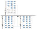
Рис. 1 Обзор функций защиты стандартных конфигураций «A» и «B»
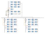
Рис. 2 Обзор функций защиты стандартных конфигураций «C» и «D»
ABB 5
Защита фидера
    REF615

4. Применение
Реле REF615 защиты фидера может поставляться либо   В стандартных конфигурациях «А» и «B» используется
с направленной, либо с ненаправленной защитой       направленная защита от замыканий на землю, если
от замыканий на землю. Направленная защита от       отходящий фидер включает фазные трансформаторы
замыканий на землю главным образом используется     тока, тороидальный трансформатор тока и систему
в сети с изолированной или компенсированной         измерения остаточного напряжения. Ток нулевой
нейтралью, тогда как ненаправленная защита от       последовательности, вычисляемый по токам фаз, может
замыканий на землю предназначена для сетей с        использоваться для защиты от двойных замыканий на
глухим или низкоомным заземлением.                  землю. Реле дополнительно оснащается защитой от
                                                    переходных/перемежающихся замыканий на землю.

Рис. 3 Защита подстанции от междуфазных замыканий и от замыканий на землю,
       использующая стандартную конфигурацию «A» или «B» с соответствующими
       параметрами. В ячейке входного фидера неиспользуемые функции защиты не
       окрашены в какой-либо цвет и обозначаются пунктирным блочным контуром.
       Реле оснащены дополнительными функциями защиты от электрической дуги,
       обеспечивающими быструю и селективную защиту от электрической дуги всего
       распределительного устройства.

6                                                                                                         ABB
Защита фидера                                                              1MRS756233
      REF615

      Стандартные конфигурации «C» и«D» включают
      ненаправленную защиту от замыканий на землю
      для отходящих фидеров, включая фазные трансфор-
      маторы тока. Ток нулевой последовательности для
      защиты от замыканий на землю извлекается из
      токов фаз. При необходимости для измерения тока
      нулевой последовательности могут использоваться
      тороидальные трансформаторы тока, особенно если
      требуется чувствительная защита от замыканий на
      землю.

      Рис. 4 Защита подстанции от междуфазных замыканий и от замыканий на землю, использующая
             стандартную конфигурацию «C» или «D» с соответствующими параметрами. В ячейке
             входного фидера неиспользуемые функции защиты не окрашены в какой-либо цвет и
             обозначаются пунктирным блочным контуром. Защита шин основывается на принципе
             блокировки, где при пуске максимальной токовой защиты отходящего фидера посылается
             сигнал блокировки на ступень токовой отсечки входного фидера. В отсутствие сигнала
             блокировки максимальная токовая защита входного фидера отключит внутреннее КЗ в
             распредустройстве (на шинах).

ABB                                                                                           7
Защита фидера
    REF615

5. Управление
Реле обеспечивает управление одним выключателем        По умолчанию дискретные каналы настраиваются
с отдельными кнопками для размыкания и замыканий.      на запись внешних или внутренних сигналов
Схемы блокировки, настраиваются с помощью              реле, например сигналов пуска или срабатывания
программной утилиты матрицы сигналов в PCM600,         ступеней реле, либо внешних сигналов блокировки
в зависимости от условий применения.                   или управления. Дискретные сигналы реле, такие
                                                       как сигналы пуска или срабатывания защиты, либо
                                                       внешние сигналы управления реле через дискретный
                                                       вход могут быть настроены на запуск записи.
6. Измерения
Реле непрерывно измеряет фазные токи, симметричные
составляющие токов и ток нулевой последовательности.   8. Регистр событий
Если реле содержит направленную защиту от
замыканий на землю, оно измеряет также остаточное      В целях сбора сведений о последовательности
напряжение. Кроме того, реле вычисляет максимальное    событий реле оснащено памятью с возможностью
усредненное значение по выбираемым пользователем       хранения 50 кодов событий с соответствующими
предустановленным интервалам времени, тепловую         отметками времени. Регистр событий облегчает
перегрузку защищаемого объекта и коэффициент           проведение подробного анализа замыканий и
асимметрии фаз на основе соотношения между токами      аварийных процессов до и после их возникновения.
обратной и прямой последовательности.
                                                       Доступ к списку последовательности событий
Доступ к измеряемым величинам осуществляется           предоставляется локально через интерфейс
локально через интерфейс пользователя на передней      пользователя на передней панели реле или удаленно
панели реле или удаленно через интерфейс связи         через интерфейс связи реле. Дополнительный
реле. Дополнительный доступ к измеряемым               доступ к сведениям возможен локально или
величинам возможен также локально или удаленно         удаленно с помощью интерфейса пользователя на
с помощью интерфейса пользователя на основе веб-       основе веб-обозревателя.
обозревателя.

                                                       9. Регистрируемые данные
7.     Регистратор аварийных
       процессов                                       Возможности реле позволяют хранить записи
                                                       о четырех замыканиях. Записи позволяют
                                                       пользователю анализировать четыре последних
Реле оснащено регистратором аварийных процессов,       события, произошедшие в энергосистеме. Каждая
имеющим до 8 аналоговых и 32 дискретных сигналь-       запись содержит значения тока и напряжения,
ных каналов. Аналоговые каналы могут настраиваться     значения продолжительности времени пусков
на запись формы сигнала или изменений измеряемых       блоков защиты, отметку времени и другие
токов и напряжения.                                    сведения. Регистрация аварийных процессов
                                                       может запускаться сигналом пуска или сигналом
Аналоговые каналы могут быть настроены на              срабатывания блока защиты либо обоими
запуск функции записи по факту повышения или           сигналами. К доступным режимам измерения
понижения измеряемой величины относительно             относятся DFT, RMS и удвоенная амплитуда. Кроме
заданных значений. Каналы дискретных сигналов          того, отдельно регистрируется максимальное
могут быть настроены на запуск функции записи          значение усреднённого тока с отметкой времени.
по нарастающему или спадающему фронту
дискретного сигнала либо по обоим фронтам.
8                                                                                                          ABB
Защита фидера                                                                            1MRS756233
      REF615

      10. Контроль выключателя 13. Управление доступом
      Функции контроля состояния реле позволяют             Для защиты реле от несанкционированного
      постоянно отслеживать рабочие характеристики          доступа и в целях обеспечения целостности
      и состояние выключателя. Контроль охватывает          информации реле снабжено четырехуровневой
      время взвода пружины, давление газа SF6, время хода   системой проверки подлинности с отдельными
      контактов и время холостого режима выключателя.       паролями, программируемыми администратором,
                                                            для уровня наблюдателя, оператора, инженера и
      Функции контроля предоставляют эксплуатационные       администратора. Действие системы управления
      данные предыстории выключателя, которые               доступом распространяется на интерфейс
      могут использоваться для планирования                 пользователя на основе веб-обозревателя и на
      профилактического обслуживания выключателя.           программную утилиту PCM600.

      11. Контроль цепей                                    14. Входы и выходы
          отключения
                                                            В зависимости от выбранной стандартной
                                                            конфигурации реле оснащаются тремя входами
      Система контроля цепей отключения непрерывно          фазных токов и одним входом тока нулевой
      отслеживает доступность и работоспособность           последовательности для ненаправленной защиты
      цепи отключения. Система контроля обеспечивает        от замыканий на землю либо тремя входами
      отслеживание разомкнутых цепей как в замкнутом,       фазных токов, одним входом тока нулевой
      так и в разомкнутом состоянии выключателя.            последовательности и одним входом остаточного
      Она также фиксирует пропадание управляющего           напряжения для направленной защиты от
      напряжения выключателя.                               замыканий на землю.

                                                            Входы фазных токов рассчитаны на номинальный
                                                            ток 1/5 A. Доступны два дополнительных входа тока
      12. Система самоконтроля                              нулевой последовательности, т. е. 1/5 A или 0,2/1 A.
          (IRF)                                             Вход на 0,2/1 A обычно используется в случаях, когда
                                                            требуется применение чувствительной защиты от
                                                            замыканий на землю и используются тороидальные
      Встроенная система самоконтроля (IRF) реле            трансформаторы тока. Вход остаточного напряжения
      постоянно отслеживает состояние оборудования          рассчитан на номинальные напряжения 100, 110, 115
      реле и работу программного обеспечения реле.          и 120 В.
      Оператор оповещается обо всех обнаруживаемых
      повреждениях и неисправностях. При обнаружении        Вход фазного тока на 1 A или 5 A, вход тока нулевой
      устойчивой неисправности реле его защитные            последовательности на 1 A или 5 A либо на 0,2 A
      функции полностью блокируются для предотвращения      или 1 A, а также номинальное напряжение входа
      его неправильной работы.                              остаточного напряжения выбираются программным
                                                            способом в реле. Кроме того, пороговые напряжения
                                                            дискретных входов 18…176 В пост. тока выбираются
                                                            путем настройки параметров реле.

                                                            Все контакты дискретных входов и выходов
                                                            произвольно конфигурируются с помощью
                                                            программной утилиты сигнальной матрицы в
                                                            PCM600.

ABB                                                                                                            9
Защита фидера
 REF615

Обзор аналоговых входов и дискретных входов/       передачи в 3 мс, реле может отправлять и получать
выходов реле:                                      двоичные сигналы от других реле (так называемая
• Четыре токовых входа                             горизонтальная связь). Реле может одновременно
• Один дополнительный вход напряжения              поддерживать связь с пятью разными клиентами IEC
  (для применения с направленной защитой от        61850-8-1.
  замыканий на землю)
• Три дискретных входа с измерением U0 и четыре    Все коммуникационные разъемы, за исключением
  дискретных входа без измерения U0                соединителя порта на передней панели, размещаются
• Два силовых выходных реле с нормально            на дополнительных встроенных модулях связи. Реле
  разомкнутыми контактами                          может подключаться к системам связи, работающим
• Два перекидных сигнальных выходных контакта      по протоколу Ethernet, с помощью разъема RJ-45
• Два двухполюсных силовых выходных контакта       (100BASE-TX) или волоконно-оптического
  с контролем цепи отключения                      соединителя LC (100BASE-FX). Если необходимо
• Один выходной контакт I, специально              подключение к сети RS-485, может использоваться
  предназначенный для RF                           10-контактный винтовой концевой зажим.

Модуль расширения входов/выходов:
                                                   Реализация на основе протокола Modbus
• Семь дискретных управляющих входов
                                                   поддерживает режимы RTU, ASCII и TCP. Помимо
• Три сигнальных выходных контакта
                                                   стандартных функциональных возможностей
                                                   Modbus реле поддерживает извлечение событий с
                                                   метками времени, загрузку файлов регистратора
15. Связь                                          аварийных процессов и хранение записей последних
                                                   замыканий. Если используется подключение Modbus
                                                   TCP, к реле могут быть подключены одновременно
Реле поддерживает два разных протокола связи:      пять клиентов.
IEC 61850 и Modbus®. Эти протоколы позволяют
получать эксплуатационные данные и осуществлять    В случае использования шины RS-485 для связи
управление. Тем не менее, некоторые функции        по протоколу Modbus RTU/ASCII, поддерживаются
связи, например горизонтальная связь между реле,   как двух, так и четырехпроводные соединения.
доступны только с протоколом связи IEC 61850.      Согласующие резисторы, а также резисторы
                                                   смещения и утечки конфигурируются с помощью
Реализация связи по протоколу IEC 61850            перемычек на плате связи, благодаря чему отсутствует
поддерживает все функции контроля и управления.    необходимость во внешних резисторах.
К тому же с помощью протокола IEC 61850-8-1
можно получить доступ к настройке параметров       Реле поддерживает следующий метод временной
и записям регистратора аварийных процессов.        синхронизации с разрешением временных отметок
Более того, с помощью профиля GOOSE протокола      в +/- 1 мс:
IEC61850-8-1, который поддерживает класс
наивысшей производительности с общим временем      На основе Ethernet:
                                                   • SNTP

 Поддерживаемые интерфейсы и протоколы связи
                                     100BASE-TX           100BASE-FX LC                RS-485
                                        RJ45
 IEC 61850-8-1                             •                      •                       -
 MODBUS RTU/ASCII                          -                       -                      •
 MODBUS TCP                                •                      •                       -
 • = поддерживается

10                                                                                                        ABB
Защита фидера                                                                   1MRS756233
      REF615

      16. Технические характеристики

      Размеры

      Ширина                            рама               177 мм
                                        корпус             164 мм
      Высота                            рама               177 (4U)
                                        корпус             160 мм
      Глубина                           корпус             155 мм
      Вес                               реле               3,5 кг
                                        запасной блок      1,8 кг

      Источник питания
      Тип:                              Тип 1                                Тип 2
      Uaux                              100, 110, 120, 220, 240 В перем.     24, 30, 48, 60 В пост.
                                        тока,                                тока
                                        50 и 60 Гц
                                        48, 60, 110, 125, 220, 250 В пост.
                                        тока
      Uaux диапазон допустимых          85...110 % от Un (85...264 В         50...120 % x Un
      изменений                         перем. тока)                         (12...72 В пост. тока)
                                        80...0,120 % от Un (38,4...300 В
                                        пост. тока)
      Пороговое напряжение пуска                                             19,2 В пост. тока
                                                                             (24 В пост. тока * 80 %)
      Потребляемая мощность                                    < 8,4 Вт/13 Вт
      в режиме ожидания (Pq)/при
      срабатывании

      Допустимые пульсации напряжения   Макс. 12 % от напряжения пост. тока (при частоте 100 Гц)
      питания пост. тока
      Максимально допустимое время                    < 50 мс при номинальном Uaux
      прерывания
      напряжения питания пост. тока
      без сброса реле
      Тип предохранителя                                        T2.5A/250 В

ABB                                                                                                   11
Защита фидера
 REF615

Измерительные входы

 Номинальная частота                                50/60 Гц ± 5 Гц
 Токовые входы          Номинальный ток, In         0,2/1 A 1)             1/5 A 2)
                        Термическая стойкость:
                        • Длительно                 4A                     20 A
                        • В течение 1 с             100 A                  500 A
                        • В течение 10 с            25 A                   100 A
                        Динамическая стойкость:
                        • В течение полупериода     250 A                  1 250 A
                        Полное входное
Защита фидера                                                           1MRS756233
      REF615

      Сигнальное выходное реле переключающего типа реле IRF
      Номинальное напряжение                           250 В перем./пост. тока
      Длительно допустимая нагрузка на контакты               5A

      Допустимый ток в течение 3,0 с                          15 A

      Допустимый ток в течение 0,5 с                          30 A

      Отключающая способность при постоянной времени цепи     1 A/0,25 A/0,15 A
      отключения L/R < 40 мс
      Минимальный ток через контакты                          100 мА при 24 В перем./пост.
                                                              тока

      Силовые выходные реле
      Двухполюсное реле мощности с функцией контроля схемы отключения
      Номинальное напряжение                           250 В перем./пост. тока
      Длительно допустимая нагрузка на контакты               8A

      Допустимый ток в течение 3,0 с                          15 A

      Допустимый ток в течение 0,5 с                          30 A

      Отключающая способность при постоянной времени цепи     5 A/3 A/1 A
      L/R
Защита фидера
 REF615

Степень защиты реле при использовании утопленного монтажа
 Передняя панель                                        IP 54
 Задняя сторона, верх реле                              IP 40

 Задняя сторона, соединительные клеммы                  IP 20

Внешние условия и испытания на воздействие окружающей среды
Условия окружающей среды
Диапазон рабочих температур                             -25...+55 °C (длительно)

Диапазон кратковременных рабочих температур             -40...+85 °C (< 16 час)
                                                        Примечание. Уменьшение
                                                        среднего времени безотказной
                                                        работы и ухудшение
                                                        производительности HMI
                                                        вне диапазона температур
                                                        -25...+55 °C
Относительная влажность
Защита фидера                                                           1MRS756233
      REF615

      (продолжение)
      Испытания на воздействие ВЧ-помех.                    В соответствии с IEC 61000-4-6
      • Кондуктивные помехи общего вида                     и
                                                            IEC 60255-22-6, уровень 3 10 В
                                                            (эдс), f = 150 кГц...80 МГц В
      • Излучаемые помехи с амплитудной модуляцией          соответствии с IEC 61000-4-3
                                                            и IEC 60255-22-3, уровень 3
                                                            10 В/м (эдс), f=80...1000 МГц и
                                                            f=1,4...2,7 ГГц
      • Излучаемые помехи с импульсной модуляцией           В соответствии с ENV 50204 и
                                                            IEC 60255-22-3, уровень 3
                                                            10 В/м, f=900 МГц
      Испытания на воздействие кратковременных помех        В соответствии с IEC 61000-4-4
                                                            и IEC 60255-22-4, класс В
      • Все входы                                           2 кВ
      • Связь                                               2 кВ
      Проверка устойчивости к импульсным перенапряжениям:   В соответствии с IEC 61000-4-5
                                                            и IEC 60255-22-5, уровень 4/3
      • Все входы                                           2 кВ, между проводом и землей,
      • Связь                                               1 кВ, между проводами
                                                            1 кВ, между проводом и землей
      Магнитное поле на частоте сети (50 Гц):               В соответствии с IEC 61000-4-8,
                                                            уровень 5
      • Длительно                                           300 A/м
      Испытание на устойчивость частоты сети:               В соответствии с IEC 60255-22-7,
                                                            класс A
      • Помехи общего вида                                  300 В, действ. значение
      • Помехи дифференциального вида                       150 В, действ. значение
      Провалы и кратковременные прерывания напряжения       В соответствии с IEC 61000-4-11
      питания                                               30 %/10 мс
                                                            60 %/100 мс
                                                            60 %/1000 мс
                                                            >95 %/5000 мс
      Испытания на излучение электромагнитных помех:        В соответствии с EN 55011,
                                                            класс A и IEC60255-25
      • Кондуктивные ВЧ-помехи (на клеммах сети)
      0,15...0,50 МГц                                       < 79 дБ (мкВ) квазимаксимум
                                                            < 66 дБ (мкВ) среднее
      0,5..0,30 МГц                                         < 73 дБ (мкВ) квазимаксимум
                                                            < 60 дБ (мкВ) среднее
      • Излучаемые ВЧ-помехи
      0...230 МГц                                           < 40 дБ (мкВ) квазимаксимум,
                                                            измеряемый на расстоянии 10 м
      230...1000 МГц                                        < 47 дБ (мкВ) квазимаксимум,
                                                            измеряемый на расстоянии 10 м

ABB                                                                                           15
Защита фидера
 REF615

Испытания изоляции и механические испытания
Испытания изоляции
Испытания электрической прочности изоляции:           В соответствии с IEC 60255-5

• Испытательное напряжение                            2 кВ, 50 Гц, 1 мин.
                                                      500 В, 50 Гц, 1 мин,
                                                      связь
Испытание при импульсном напряжении:                  В соответствии с IEC 60255-5

• Испытательное напряжение                            5 кВ, однополярные импульсы,
                                                      длительность импульса 1,2/50
                                                      мкс, энергия источника 0,5 Дж
                                                      1 кВ, однополярные импульсы,
                                                      длительность импульса 1,2/50
                                                      мкс, энергия источника 0,5 Дж,
                                                      связь
Измерения сопротивления изоляции                      В соответствии с IEC 60255-5

• Сопротивление изоляции                              >100 МОм, 500 В пост. тока

Защитное контактное сопротивление                     В соответствии с IEC 60255-27
• Сопротивление
Защита фидера                                                                                      1MRS756233
      REF615

      Функции защиты

      Трехфазная ненаправленная максимальная токовая защита (PHxPTOC)

       Погрешность              В зависимости от частоты измеряемого тока: fn ±2 Гц
       по току
                                PHLPTOC                                 ±1,5 % заданного значения или ±0,002 x In
       срабатывания
                                PHHPTOC                                 ±1,5 % заданного значения или ±0,002 x In
                                и                                       (при токах в диапазоне 0,1…10 x In)
                                PHIPTOC                                 ±5,0 % заданного значения
                                                                        (при токах в диапазоне 10…40 x In)
       Время пуска 1) 2)                                                Минимальное Типовое                Максимальное
                                PHIPTOC:
                                IПовреждение =
                                2 x заданная Уставка пуска              16 мс             19 мс            23 мс
                                IПовреждение =
                                10 x заданная Уставка пуска             11 мс             12 мс            14 мс
                                PHHPTOC и PHLPTOC:
                                IПовреждение =
                                2 x заданная Уставка пуска              22 мс             24 мс            25 мс
       Время                                                            Минимальное Типовое                Максимальное
       срабатывания             PHIPTOC:
       без выдержки 1) 3)       IПовреждение = 2 x заданная
                                Уставка пуска                           17 мс             21 мс            25 мс
                                IПовреждение = 10 x заданная
                                Уставка пуска                           12 мс             15 мс            16 мс
                                PHHPTOC и PHLPTOC:
                                IПовреждение =
                                2 x заданная Уставка пуска              25 мс             27 мс            29 мс
       Время возврата                                                   < 40 мс
       Коэффициент возврата                                             Типовой 0,96
       Задержка пуска                                                   < 30 мс
       Погрешность времени срабатывания для                             ±1,0 % заданного значения или ±20 мс
       независимой временной характеристики
       Погрешность времени срабатывания для                             ±5,0 % теоретического значения или
       обратнозависимой временной характеристики                        ±20 мс 4)
       Подавление гармоник                                              RMS: Подавление отсутствует DFT: -50 дБ
                                                                        при f = n x fn, где n = 2, 3, 4, 5,…
                                                                        Двойная амплитуда: Подавление отсутствует
                                                                        Двойная амплитуда + резервирование:
                                                                        Подавление отсутствует
      1) Уставка времени задержки срабатывания = 0,02 с, Тип характеристики срабатывания = независимая характеристика IEC,
         Режим измерения = стандартный (зависит от ступени), ток до замыкания = 0,0 x In, fn = 50 Гц, ток замыканий на
         землю с номинальной частотой, инжектируемый с произвольно выбранным углом фазы, результаты основаны на
         статистическом распределении 1000 измерений
      2) Включает задержку сигнального выходного реле
      3) Включает задержку силового выходного контакта
      4) Максимальная уставка пуска = 2,5 x In, диапазон коэффициента уставки пуска от 1,5 до 20

ABB                                                                                                                      17
Защита фидера
 REF615

Ненаправленная защита от замыканий на землю (EFxPTOC)

 Погрешность               В зависимости от частоты измеряемого тока: fn ±2 Гц
 по току
                           EFLPTOC                                ±1,5 % заданного значения или ±0,002 x In
 срабатывания
                           EFHPTOC                                ±1,5 % заданного значения или ±0,002 x In
                           и                                      (при токах в диапазоне 0,1…10 x In)
                           EFIPTOC                                ±5,0 % заданного значения
                                                                  (при токах в диапазоне 10…40 x In)

 Время пуска 1) 2)                                                Минимальное Типовое               Максимальное
                           EFIPTOC:
                           IПовреждение =
                           2 x заданная Уставка пуска             16 мс            19 мс            23 мс
                           IПовреждение =
                           10 x заданная Уставка пуска            11 мс            12 мс            14 мс
                           EFHPTOC и EFLPTOC:
                           IПовреждение = 2 x заданная
                           Уставка пуска                          22 мс            24 мс            25 мс
 Время                                                            Минимальное Типовое               Максимальное
 срабатывания              EFIPTOC:
 без выдержки 1) 3)        IПовреждение =
                           2 x заданная Уставка пуска             19 мс            23 мс            27 мс
                           IПовреждение =
                           10 x заданная Уставка пуска            14 мс            16 мс            17 мс
                           EFHPTOC и EFLPTOC:
                           IПовреждение =
                           2 x заданная Уставка пуска             24 мс            27 мс            29 мс
 Время возврата                                                   < 40 мс
 Коэффициент возврата                                             Типовой 0,96
 Задержка пуска                                                   < 30 мс
 Погрешность времени срабатывания для                             ±1,0 % заданного значения или ±20 мс
 независимой временной характеристики
 Погрешность времени срабатывания для                             ±5,0 % теоретического значения или
 обратнозависимой временной характеристики                        ±20 мс 4)
 Подавление гармоник                                              RMS: Подавление отсутствует DFT: -50 дБ
                                                                  при f = n x fn, где n = 2, 3, 4, 5,…
                                                                  Двойная амплитуда: Подавление
                                                                  отсутствует
1)   Уставка времени задержки срабатывания = 0,02 с, Тип характеристики срабатывания = независимая характеристика IEC
2)   Включает задержку сигнального выходного реле
3)   Включает задержку силового выходного контакта
4)   Максимальная уставка пуска = 2,5 x In, диапазон коэффициента уставки пуска от 1,5 до 20

18                                                                                                                      ABB
Защита фидера                                                                                     1MRS756233
      REF615

      Направленная защита от замыканий на землю (DEFxPDEF)

       Погрешность             В зависимости от частоты измеряемого тока: fn ±2 Гц
       по току                                                      Ток:
                               DEFLPDEF
       срабатывания                                                 ±1,5 % заданного значения или ±0,002 x In
                                                                    Напряжение:
                                                                    ±1,5 % заданного значения или ±0,002 x Un
                                                                    Фазовый угол:
                                                                    ±2°
                               DEFHPDEF                             Ток:
                                                                    ±2 % заданного значения или ±0,003 x In
                                                                    (при токах в диапазоне 0,1…10 x In)
                                                                    ±5,0 % заданного значения
                                                                    (при токах в диапазоне 10…40 x In)
                                                                    Напряжение:
                                                                    ±1,5 % заданного значения или ±0,01 x Un
                                                                    Фазовый угол:
                                                                    ±2°
       Время пуска 1) 2)                                            Минимальное Типовое               Максимальное
                               DEFHPDEF и
                               DEFLPTDEF:
                               IПовреждение =
                               2 x заданная Уставка пуска           61 мс            64 мс            66 мс
       Время                                                        Минимальное Типовое               Максимальное
       срабатывания            DEFHPDEF и
       без выдержки 1) 3)      DEFLPDEF:
                               IПовреждение =
                               2 x заданная Уставка пуска           62 мс            67 мс            69 мс
       Время возврата                                               < 40 мс
       Коэффициент возврата                                         Типовой 0,96
       Задержка пуска                                               < 30 мс
       Погрешность времени срабатывания для                         ±1,0 % заданного значения или ±20 мс
       независимой временной характеристики
       Погрешность времени срабатывания                             ±5,0 % теоретического значения или ±20 мс 4)
       для обратнозависимой временной
       характеристики
       Подавление гармоник                                          RMS: Подавление отсутствует DFT: -50 дБ
                                                                    при f = n x fn, где n = 2, 3, 4, 5,…
                                                                    Двойная амплитуда: Подавление отсутствует
      1) Уставка времени задержки срабатывания = 0,02 с, Тип характеристики срабатывания = независимая характеристика
         IEC, Режим измерения стандартный (зависит от ступени), ток до замыкания = 0,0 x In, fn = 50 Гц, ток замыканий на
         землю с номинальной частотой, инжектируемый с произвольно выбранным углом фазы, результаты основаны на
         статистическом распределении 1000 измерений
      2) Включает задержку сигнального выходного реле
      3) Включает задержку силового выходного контакта
      4) Максимальная уставка пуска = 2,5 x In, диапазон коэффициента уставки пуска от 1,5 до 20

ABB                                                                                                                     19
Защита фидера
     REF615

Защита от переходных/перемежающихся замыканий на землю (INTRPTEF)

 Погрешность тока срабатывания (критерии U0                 В зависимости от частоты измеряемого
 с защитой от переходных замыканий)                         тока: fn = ±2 Гц
                                                            ±1,5 % заданного значения или ±0,002 x Un
 Погрешность времени срабатывания                           ±1,0 % заданного значения или ±20 мс
 Подавление гармоник                                        DFT: -50 дБ при f = n x fn, где n = 2, 3, 4, 5

Защита по току обратной последовательности фаз (NSPTOC)

     Погрешность по току срабатывания                       В зависимости от частоты
                                                            измеряемого тока: fn = ±2 Гц
                                                            ±1,5 % заданного значения или ±0,002 x In
     Время пуска   1) 2)
                                                            Минимальное Типовое                  Максимальное
                            IПовреждение =
                            2 x заданная Уставка пуска      22 мс              24 мс             25 мс
                            IПовреждение =
                            0 x заданная Уставка пуска      14 мс              16 мс             17 мс
     Время                                                  Минимальное Типовое                  Максимальное
     срабатывания           IПовреждение =
     без выдержки 1) 3)     2 x заданная Уставка пуска      24 мс              26 мс             28 мс
     Время возврата                                         < 40 мс
     Коэффициент возврата                                   Типовой 0,96
     Задержка пуска                                         < 35 мс
     Погрешность времени срабатывания для                   ±1,0 % заданного значения или ±20 мс
     независимой временной характеристики
     Погрешность времени срабатывания для обрат- ±5,0 % теоретического значения или ±20 мс 4)
     нозависимой временной характеристики
     Подавление гармоник                                    DFT: -50 дБ при f = n x fn, где
                                                            n = 2, 3, 4, 5,…
1)
      Уставка времени задержки срабатывания = 0,02 с, Тип характеристики срабатывания = независимая характеристика
      IEC, ток обратной последовательности до замыкания = 0,0, fn = 50 Гц, результаты основаны на статистическом
      распределении 1000 измерений
2)
      Включает задержку сигнального выходного реле
3)
      Включает задержку силового выходного контакта
4)
      Максимальная уставка пуска = 2,5 x In, диапазон коэффициента уставки пуска от 1,5 до 20

Защита от обрыва фазы (PDNSPTOC)

     Погрешность по току срабатывания                        В зависимости от частоты измеряемого
                                                             тока: fn ±2 Гц
                                                             ±2 % заданного значения
     Время пуска                                             < 70 мс
     Время возврата                                          < 40 мс
     Коэффициент возврата                                    Типовой 0,96
     Задержка пуска                                          < 35 мс
     Погрешность времени срабатывания для                    ±1,0 % заданного значения или ±20 мс
     независимой временной характеристики
     Подавление гармоник                                     DFT: -50 дБ при f = n x fn, где n = 2, 3, 4, 5,…

20                                                                                                                   ABB
Защита фидера                                                                                       1MRS756233
      REF615

      Трехфазная защита от тепловой перегрузки (T1PTTR)

       Погрешность по току срабатывания                         В зависимости от частоты измеряемого тока:
                                                                fn ±2 Гц
                                                                Измерение тока: ±0,5 % или ±0,002 x In
                                                                (при токах в диапазоне 0,01…4,00 x In)
       Погрешность времени срабатывания                         ±2,0 % или ±0,50 с

      Устройство резервирования отказа выключателя (CCBRBRF)

       Погрешность по току срабатывания                         В зависимости от частоты измеряемого тока:
                                                                fn ±2 Гц
                                                                ±1,5 % заданного значения или ±0,002 x In
       Погрешность времени срабатывания                         ±1,0 % заданного значения или ±20 мс

      Датчик броска тока намагничивания в 3-фазном трансформаторе (INRPHAR)

       Погрешность по току срабатывания                         При частоте f = fn
                                                                Измерение тока:
                                                                ±1,5 % заданного значения или ±0,002 x In
                                                                Измерение коэффициента I2f/I1f: ±5,0 %
                                                                заданного значения
       Время возврата                                           +35 мс / -0 мс
       Коэффициент возврата                                     Типовой 0,96
       Погрешность времени срабатывания                         +35 мс / -0 мс

      Защита от электрической дуги (ARCSARC)

       Погрешность по току срабатывания                         ±3 % заданного значения или ±0,01 x In
       Время срабатывания                                       Минимальное Типовое                      Максимальное
                                    Критерий срабатыва-
                                    ния = "свет+ток" 1) 2)      9 мс               12 мс                 15 мс
                                    Критерий срабатыва-
                                    ния = "только свет" 2)      9 мс               10 мс                 12 мс
       Время возврата                                           < 40 мс
       Коэффициент возврата                                     Типовой 0,96
      1) Фазный ток пуска = 1,0 x In, ток до замыкания = 2,0 x заданный Фазный ток пуска, fn = 50 Гц, замыкание с
         номинальной частотой, результаты основаны на статистическом распределении 200 измерений
      2) Включает задержку силового выходного контакта

      Функции управления

      Автоматическое повторное включения (DARREC)

       Погрешность по току срабатывания                         ±1,0 % заданного значения или ±20 мс

ABB                                                                                                                 21
Защита фидера
 REF615

17. Параметры отображения
Реле поставляется с двумя дополнительными          прокрутке экрана и улучшен обзор информации.
устройствами отображения информации (дисплеями),   Большой дисплей предназначен для случаев частого
большим и малым. Оба ЖК-дисплея предоставляют      использования интерфейса пользователя передней
полный набор функциональных возможностей           панели, тогда как малый дисплей рассчитан на
интерфейса пользователя на передней панели с       управляемые удаленно подстанции, где необходимость
перемещениями по меню и видами меню.               в локальном доступе к реле с помощью интерфейса
                                                   пользователя передней панели возникает в редких
Большой индикатор имеет более удобную переднюю     случаях.
панель, при этом уменьшена необходимость в

         Рис. 5 Малый дисплей                              Рис. 6 Большой дисплей

Малый индикатор
Размер знаков 1)                                    Отображаемые              Число знаков на
                                                       строки                     строку
Малый, моноширинный (6x12 точек)                            5                         20
Большой, переменной ширины (13x14 точек)                    4                   8 или более 1)
Большой индикатор
Размер знаков 1)                                    Отображаемые              Число знаков на
                                                       строки                     строку
Малый, моноширинный (6x12 точек)                            10                        20
Большой, переменной ширины (13x14 точек)                    8                   8 или более 1)
1) В зависимости от выбранного языка

22                                                                                                      ABB
Защита фидера                                                                                   1MRS756233
      REF615

      18. Варианты монтажа
      С помощью подходящих монтажных принадлеж-         •     Высота: 161,5 ± 1 мм
      ностей стандартный корпус реле серии 615 можно    •     Ширина: 165,5 ± 1 мм
      монтировать полностью утопленным ("заподлицо"),
      полуутопленным или на стену. Корпуса реле,
      монтируемые заподлицо или на стену, могут также
      устанавливаться в наклонном положении (25°) с     19. Корпус реле и съемный
      использованием специальных принадлежностей.           блок реле
      Более того, реле могут монтироваться в любом
      стандартном 19-дюймовом релейном шкафу с          По соображениям безопасности корпуса реле,
      помощью 19-дюймовых монтажных панелей,            рассчитанные на измерение токов, оснащаются
      доступных с вырезами под одно или два реле. В     автоматически переключающимися контактами
      альтернативном варианте реле можно установить     с целью закорачивания вторичных цепей
      в 19-дюймовые релейные шкафы с помощью            трансформатора тока в случаях, когда блок реле
      приборных рам Combiflex высотой 4U.               вынимается из корпуса. Более того, корпус реле
                                                        оснащается механической кодовой системой,
      Для периодических испытаний корпуса реле могут    предотвращающей вставку съемных блоков от
      оснащаться испытательным блоками типа RTXP 18,    токовых реле в корпус для реле напряжения и
      которые монтируются рядом с корпусами реле.       наоборот, т. е. корпуса реле предназначены для
                                                        определённого типа съемного блока реле.
      Варианты монтажа:
      •      Утопленный монтаж (“заподлицо”)
      •      Полуутопленный монтаж
      •      Полуутопленный монтаж с наклоном 25°
      •      Монтаж в стойке
      •      Настенный монтаж
      •      Монтаж на 19-дюймовую раму
      •      Монтаж с испытательным блоком RTXP 18
             в 19-дюймовую стойку
      Вырез в панели для утопленного монтажа:

                                                                                                              12
                                                                                                                7
                                                                            221,25 (5U)

                                                                                                25°

                                                                                          10
                                                                                            7

                                                                                                          5

           153                              103

                        41                              91

       Рис. 7 Утопленный монтаж           Рис. 8 Полуутопленный            Рис. 9 Полуутопленный мон-
               (“заподлицо”)                     монтаж                           таж с наклоном 25°

ABB                                                                                                                 23
Защита фидера
 REF615

20. Данные для выбора
    и заказа изделия
Реле защиты идентифицируется по типу реле и        Для создания номера заказа на укомплектованные
этикетке с серийным номером. Этикетка находится    реле защиты пользуйтесь сведениями о коде заказа,
над HMI в верхней части съемного блока. Этикетка   показанными на рис. 10.
с номером заказа находится на боковой стороне
съемного модуля и внутри корпуса. Номер заказа
состоит из строки кодов, формируемых из названий
аппаратного и программного модулей реле.

                                                                H B FCACAB N B B 1AC N 1 XA

  № ОПИСАНИЕ
  1    Реле
       Реле серии 616 (включая корпус)                    H
  2    Стандарт
       IEC                                                B
  3    Основное применение
       Защита фидера                                      F

                                                        H B FCACAB N B B 1AC N 1 XA

 № ОПИСАНИЕ
 4    Функциональное применение 1)
      Стандартная конфигурация   A    B     C      D
5=6 Аналоговые входы
      4 I + U0 (I 0 1/5 A)       AA   AA
      4 I + U0 (I 0 0,2/1 A)     AB   AB
      4 I (I0 1/5 A)                       AC      AC
      4 I (I 0 0,2/1 A)                    AD      AD
7=8 Дискретные входы/выходы
      3 BI + 6 BO                AA
      4 BI + 6 BO                          AB
      10 BI + 9 BO                    AC
      11 BI + 9 BO                                 AD

1) Выбранная стандартная конфигурация определяет
 обязательное и дополнительное оборудование.
 Выберите правильные символы из столбца стандартной
 конфигурации «A», «B», «C» или «D».

24                                                                                                     ABB
Защита фидера                                                            1MRS756233
      REF615

                                                                H B FCACAB N B B 1AC N 1 XA

       № ОПИСАНИЕ
       9    Последовательная связь
            RS485                             A
            Нет                                       N     N
       10   Свяь Ethernet
            Ethernet 100BaseFX (L C)                  A
            Ethernet 100BaseT X (RJ45)                B
            Нет                               N             N
       11   Протокол связи 1)
            IEC 61850                                 A     A
            Modbus                            B      B

      1) Выбранный модуль связи (разряд 9{10) определяет
        доступные протоколы связи. Выберите протокол из
        соответствующей колонки.

                                                                H B FCACAB N B B 1AC N 1 XA

       № ОПИСАНИЕ
       12   Язык
            Английский                                      1
       13   Передняя панель
            Малый ЖК{индикатор                              A
            Большой ЖК{индикатор                            B
       14   Вариант 1
            Автоматическое повторное включение              A
            Защита от электрической дуги 1)                 B
            Защита от электрической дуги и автоматическое
            повторное включение 1)                          C
            Нет                                             N
       15   Вариант 2
            Нет                                             N
       16   Источник питания
            48...250 В=, 100...240 В~                       1
            24...60 В=                                      2
       17   Свободный разряд
            Свободный                                       X
       18   Версия
            Версия 1.0                                      A

      1) Защита от электрической дуги расположена в модуле связи
       (разряды 9{10). Таким образом, для выполнения защиты
       от электрической дуги всегда требуется модуль связи.

ABB                                                                                      25
Защита фидера REF615 Пример кода: H B F C A C A B N B B 1 A C N 1 X A Код заказа Разряд (#) 1 2 3 4 5 6 7 8 9 10 11 12 13 14 15 16 17 18 Код Рис. 10 Код заказа на укомплектованные реле 26 ABB
Защита фидера                                                                          1MRS756233
      REF615

      21. Принадлежности и
          данные для заказа
      Изделие                                                                 № заказа
      Кабели
      Кабель длиной 1,5 м для оптических датчиков системы защиты от           1MRS120534-1.5
      электрической дуги
      Кабель длиной 3,0 м для оптических датчиков системы защиты от           1MRS120534-3.0
      электрической дуги
      Кабель длиной 5,0 м для оптических датчиков системы защиты от           1MRS120534-5.0
      электрической дуги
      Монтажные принадлежности
      Комплект для полуутопленного монтажа                                    1MRS050696
      Комплект для настенного монтажа                                         1MRS050697
      Комплект для полуутопленного наклонного монтажа                         1MRS050831
      Комплект для монтажа в 19-дюймовой стойке с вырезом под одно реле 1MRS050694
      Комплект для монтажа в 19-дюймовой стойке с вырезом под два             1MRS050695
      реле
      Монтажный комплект для RTXP 18 (4U Combiflex)                           1MRS051010
      Монтажный кронштейн для каркаса Combiflex высотой 4U                    1MRS050779
      Испытательные блоки:
      Монтажный комплект испытательного блока RTXP 18 для                     1MRS050783
      19-дюймовой стойки, одно реле

      22. Программные утилиты

      Реле поставляется в виде готового к работе блока.
      Заводские уставки параметров могут быть изменены с   При использовании интерфейса пользователя на
      помощью интерфейса пользователя передней панели,     основе веб-обозревателя к реле можно получить
      интерфейса пользователя на основе веб-обозревателя   доступ локально или удаленно с помощью веб-
      (WebHMI) или программной утилиты PCM600 в            обозревателя (IE 7.0 или более поздняя версия).
      сочетании с программным стыковочным пакетом для      По соображениям безопасности интерфейс
      конкретного реле.                                    пользователя на основе веб-обозревателя отключен
                                                           по умолчанию. Этот интерфейс может быть
      PCM600 предоставляет широкий выбор функций           включен с помощью программной утилиты PCM600
      конфигурирования реле, таких как конфигурирование    или интерфейса пользователя передней панели.
      сигналов реле с помощью программной утилиты          Посредством программной утилиты PCM600
      матрицы сигналов, а также конфигурирование связи     функциональные возможности данного интерфейса
      устройства IEC 61850, включая горизонтальную связь   могут ограничиваться доступом только для чтения.
      (GOOSE) между несколькими реле.

      Программные утилиты
      Утилиты конфигурирования, настройки                         Версия
      и системные средства
      PCM600                                                      2.0 или более поздняя
      Интерфейс пользователя на основе веб-обозревателя           IE 7.0 или более поздняя
      Программный стыковочный пакет EF615                         1,0 или более поздняя
      MicroSCADA Pro                                              9.2 SP1 или более поздняя
ABB                                                                                                      27
Защита фидера
 REF615

Обзор функций утилит

Функция                                         WebHMI   PCM600
Конфигурирование сигналов реле (утилита           -
                                                           •
матрицы сигналов)
Конфигурирование связи устройства IEC 61850,      -
                                                           •
GOOSE
Настройка параметров реле                         •        •
Контроль сигналов                                 •        •
Обслуживание регистратора аварийных процессов     -        •
Анализ записей об аварийных процессах             -
                                                           •
Просмотр событий                                  •        -

Просмотр светодиодов аварийной сигнализации       •        •
Просмотр векторной диаграммы                      •        -

Сохранение в реле настроек параметров реле        •        •
Сохранение настроек параметров в программном      -
                                                           •
инструменте
Управление системой контроля доступа              •        •
• = поддерживается

28                                                                ABB
Защита фидера 1MRS756233
REF615
23. Схемы соединений
REF615
X120 X100
1 + 1
BI 1 Uaux
2 2
-
3 3
BI 2
IRF
4
4 5
BI 3
PO1
5
Uo
6 6
7 7
I L1
8 PO2
9
I L2 8
10 9
11 10
I L3 SO1
12
13 11
Io 12
14 13
SO2
X110 15
14
3 16
BI 2
4 PO3
5 17
BI 3 18
6
TCS1 19
20
BI 4 PO4
7
21
8 22
BI 5
9 TCS2 23
BI 6
10
X110
11
BI 7 14
12
SO1
BI 8 16
13 15
17
SO2
X1 19
1) 2) 18
LAN 20
SO3
X5 1) 3) 22
1 GND 21
2 GNDC
3
4
5
6 AGND
7 / TX
B/-
8 A/+
9 B/-
/ RX
10 A/+
X13
1)
Вход 1 оптического датчика
X14
1)
Вход 2 оптического датчика
X15
1)
Вход 3 оптического датчика
1) Дополнительный
2) 100BaseFx / LC или 100BaseTx / RJ-45
3) Последовательная шина RS-485
Рис. 11: Схема соединений стандартной конфигурации «B»
ABB 29
Защита фидера
 REF615

                                                   REF615
               X120                                                                 X100
                 1                                                            +      1
                                     BI 1                                    Uaux
                 2                                                                   2
                                                                              -
                 3                                                                   3
                                     BI 2
                                                                       IRF
                                                                                     4
                 4                                                                   5
                                     BI 3

                                                                       PO1
                 5
                                     BI 4
                 6                                                                   6
                 7                                                                   7
                                   I L1
                 8                                                     PO2
                 9
                                   I L2                                              8
                10                                                                   9
                11                                                                   10
                                   I L3                                SO1
                12
                13                                                                   11
                                   Io                                                12
                14                                                                   13
                                                                       SO2
               X110                                                                  15
                                                                                     14
                 3                                                                   16
                                     BI 2                       PO3
                 4

                 5                                                                   17
                                     BI 3                                            18
                 6                                              TCS1                 19
                                                                                     20
                                     BI 4                       PO4
                 7
                                                                                     21
                 8                                                                   22
                                     BI 5                       TCS2
                 9                                                                   23

                                     BI 6
                10
                                                                                    X110
                11                                                                   14
                                     BI 7
                12                                                 SO1
                                                                                     16
                                     BI 8                                            15
                13                                                                   17
                                                                   SO2
                                                                                     19
               X1
                             1) 2)
                                                                                     18
                      LAN                                                            20
                                                                   SO3
               X5                       1) 3)                                        22
                1     GND                                                            21
                2     GNDC
                3
                4
                5
                6     AGND
                7     B/- / TX
                8     A/+
                9     B/-
                            / RX
               10     A/+

               X13
                                                1)
                      Вход 1 оптического датчика

               X14
                                                   1)
                      Вход 2 оптического датчика

               X15
                                                   1)
                      Вход 3 оптического датчика
                      1) Необязательный
                      2) 100BaseFx / LC или 100BaseTx / RJ-45
                      3) Последовательная шина RS-485

Рис. 12: Схема соединений стандартной конфигурации «D»

30                                                                                         ABB
Защита фидера                                                               1MRS756233
      REF615

      24. Функции, коды
          и символы

      Функции, коды и символы REF615

      Функции защиты                                      IEC 61850   IEC 60617 ANSI
      Трехфазная ненаправленная максимальная токовая      PHLPTOC     3I>         51P-1
      защита, низкая ступень
      Трехфазная ненаправленная максимальная токовая      PHHPTOC     3I>>        51P-2
      защита, высокая ступень
      Трехфазная ненаправленная максимальная токовая
      защита, без выдержки времени (токовая отсечка)      PHIPTOC     3I>>>       50P/51P
      Направленная защита от замыканий на землю, низкая   DEFLPDEF    I0>→        67N-1
      ступень
      Направленная защита от замыканий на землю,          DEFHPDEF    I0>>→       67N-2
      высокая ступень
      Защита от переходных/перемежающихся замыканий       INTRPTEF    I0>→ IEF    67N-IEF
      на землю
      Ненаправленная защита от замыканий на землю,        EFLPTOC     I 0>        51N-1
      низкая ступень (SEF)
      Ненаправленная защита от замыканий на землю,        EFLPTOC     I 0>        51N-1
      низкая ступень
      Ненаправленная защита от замыканий на землю,        EFHPTOC     I0>>        51N-2
      высокая ступень
      Ненаправленная защита от замыканий на землю, без    EFIPTOC     I0>>>       50N/51N
      выдержки времени (токовая отсечка)
      Максимальная токовая защита обратной                NSPTOC      I2>         46
      последовательности
      Защита от обрыва фазы                               PDNSPTOC    I2/I1>      46PD
      Защита от тепловой перегрузки                       T1PTTR      3Ith>       49F
      Устройство резервирования отказа выключателя        CCBRBRF     3I>/I0>BF   51BF/51NBF
      Датчик броска тока намагничивания в 3-фазном        INRPHAR     3I2f>       68
      трансформаторе
      Защита от электрической дуги                        ARCSARC     ARC         50L/50NL
      Функции управления
      Управление силовым выключателем                     CBXCBR      I ↔ O CB
      Автоматическое повторное включение                  DARREC      O→ I        79
      Функции измерения
      Трехфазный ток                                      CMMXU       3I          3I
      Составляющие токовой последовательности             CSMSQI      I1,I2 ,I0   I1,I2,I0
      Ток нулевой последовательности                      RESCMMXU    I0          IN
      Остаточное напряжение                               RESVMMXU    U0          VN
      Функция регистратора аварийных процессов
      Регистратор аварийных процессов                     DRRDRE      DREC        DREC
      Функция контроля состояния выключателя
      Контроль состояния выключателя                      SSCBR       CBCM        CBCM
      Функция контроля

ABB                                                                                          31
© Авторские права ABB, 2008 г. С сохранением всех прав.
                                   1MRS756233 A

ABB Oy
Distribution Automation
П/Я 699
FI-65101 Vaasa, Финляндия
Тел.      +358 10 22 11
Факс      +358 10 22 41094
www.abb.com/substationautomation
- Page 1
Application Manual Feeder Protection and Control REF615… - Page 3
Document ID: 1MRS756378 Issued: 04.03.2009 Revision: D Product version: 2.0 © Copyright 2009 ABB. All rights reserved… - Page 4
Copyright This document and parts thereof must not be reproduced or copied without written permission from ABB, and the contents thereof must not be imparted to a third party, nor used for any unauthorized purpose. The software or hardware described in this document is furnished under a license and may be used, copied, or disclosed only in accordance with the terms of such license. - Page 5
In case any errors are detected, the reader is kindly requested to notify the manufacturer. Other than under explicit contractual commitments, in no event shall ABB be responsible or liable for any loss or damage resulting from the use of this manual or the application of the equipment. - Page 6
(Low-voltage directive 2006/95/ EC). This conformity is the result of a test conducted by ABB in accordance with Article 10 of the directive in agreement with the product standards EN 50263 and EN 60255-26 for the EMC directive, and with the product standards EN 60255-6 and EN 60255-27 for the low voltage directive. -
Page 7: Table Of Contents
Product documentation set…………8 Document revision history………….9 Related documentation…………..10 Document symbols and conventions……….10 Safety indication symbols…………10 Document conventions…………..11 Functions, codes and symbols…………11 Section 2 REF615 overview…………15 Overview……………….15 Product version history…………..16 PCM600 and IED connectivity package version……16 Operation functionality…………..16 Standard configurations……………16 Optional functions…………….18 Physical hardware…………….19…
- Page 8
Applications……………..80 Functions………………80 Default I/O connections…………81 Functional diagrams…………..82 Functional diagrams for protection………82 Functional diagram for disturbance recorder and trip circuit supervision…………..88 Functional diagrams for control and interlocking….89 Standard configuration F including directional overcurrent protection with voltage protection………….93 REF615 Application Manual… - Page 9
Three-phase directional overcurrent protection DPHxPDOC…………….140 Identification……………..140 Functionality……………..140 Application…………….140 Three-phase thermal overload protection for overhead lines and cables T1PTTR…………..143 Identification……………..143 Functionality……………..143 Application…………….144 Earth-fault protection…………..145 Non-directional earth-fault protection EFxPTOC…….145 Identification……………..145 Functionality……………..145 Application…………….145 Directional earth-fault protection DEFxPDEF……146 Identification……………..146 Functionality……………..146 Directional earth-fault principles………..146 Application…………….152 REF615 Application Manual… - Page 10
Functionality……………..168 Application…………….168 Residual overvoltage protection ROVPTOV……169 Identification……………..169 Functionality……………..169 Application…………….169 Negative sequence overvoltage protection NSPTOV….170 Identification……………..170 Functionality……………..170 Application…………….170 Positive sequence undervoltage protection PSPTUV….171 Identification……………..171 Functionality……………..171 Application…………….171 Section 6 Protection related functions……….181 Three-phase inrush detector INRPHAR………181 Identification…………….181 Functionality…………….181 Application……………..181 REF615 Application Manual… - Page 11
Application……………..201 Section 9 Measurement functions……….205 Basic measurements…………..205 Three-phase current CMMXU………..205 Identification……………..205 Three-phase voltage VMMXU………..205 Identification……………..205 Neutral current RESCMMXU………….205 Identification……………..205 Residual voltage RESVMMXU……….205 Identification……………..205 Sequence current CSMSQI…………206 Identification……………..206 Phase sequence voltage VSMSQI……….206 Identification……………..206 Three-phase power and energy PEMMXU……..206 REF615 Application Manual… - Page 12
Fast trip in Switch on to fault……….223 Section 11 Requirements for measurement transformers….225 Current transformers…………..225 Current transformer requirements for non-directional overcurrent protection…………..225 Current transformer accuracy class and accuracy limit factor………………225 Non-directional overcurrent protection………226 Example for non-directional overcurrent protection….227 Section 12 Glossary……………229 REF615 Application Manual… -
Page 13: Section 1 Introduction
This manual addresses the protection and control engineer responsible for planning, pre-engineering and engineering. The protection and control engineer must be experienced in electrical power engineering and have knowledge of related technology, such as communication and protocols. REF615 Application Manual…
-
Page 14: Product Documentation
The manual provides procedures for energizing and checking of external circuitry, setting and configuration as well as verifying settings and performing directional tests. The chapters are organized in chronological order in which the IED should be commissioned. REF615 Application Manual…
-
Page 15: Document Revision History
A/20.12.2007 First release B/08.02.2008 Content updated C/02.07.2008 Content updated to correspond to the product version D/04.03.2009 Content updated to correspond to the product version Download the latest revision of the document from the ABB web site http://www.abb.com/substationautomation. REF615 Application Manual…
-
Page 16: Related Documentation
The tip icon indicates advice on, for example, how to design your project or how to use a certain function. Although warning hazards are related to personal injury, it should be understood that operation of damaged equipment could, under certain operational conditions, result REF615 Application Manual…
-
Page 17: Document Conventions
DPHLPDOC2 3I> → (2) 67-1 (2) Three-phase directional overcurrent, DPHHPDOC1 3I>> → 67-2 high stage Arc protection ARCSARC1 ARC (1) 50L/50NL (1) ARCSARC2 ARC (2) 50L/50NL (2) ARCSARC3 ARC (3) 50L/50NL (3) Table continues on next page REF615 Application Manual…
- Page 18
TCS (1) TCM (1) TCSSCBR2 TCS (2) TCM (2) Fuse failure supervision SEQRFUF1 FUSEF Disturbance recorder RDRE1 Circuit breaker condition monitoring SSCBR1 CBCM CBCM Three-phase current measurement CMMXU1 Sequence current measurement CSMSQI1 Table continues on next page REF615 Application Manual… - Page 19
Section 1 1MRS756378 D Introduction Function IEC 61850 IEC 60617 IEC-ANSI Residual current measurement RESCMMXU1 Residual voltage measurement RESVMMXU1 Three-phase voltage measurement VMMXU1 Sequence voltage measurement VSMSQI1 Three-phase power and energy PEMMXU1 P, E P, E measurement REF615 Application Manual… -
Page 21: Section 2 Ref615 Overview
Section 2 REF615 overview Overview REF615 is a native IEC 61850 feeder protection IED for selective short-circuit, overcurrent and earth-fault protection. It is applicable to all types of radial isolated neutral networks, resistant earthed networks and compensated networks. REF615 is part of a product family that will cover many protection applications for utility and industry customers.
-
Page 22: Product Version History
• Firmware Update Tool • IED Configuration Migration Tool (ICM) • Lifecycle Traceability Tool Download connectivity packages from the ABB web site http:// www.abb.com/substationautomation Operation functionality 2.2.1 Standard configurations The IED is available with six alternative standard configurations. The table indicates the functions supported by the different IED configurations.
- Page 23
Section 2 1MRS756378 D REF615 overview Table 2: Standard configurations Description Std. conf. Non-directional overcurrent and directional earth-fault protection A and B Non-directional overcurrent and non-directional earth-fault protection C and D Non-directional overcurrent and directional earth-fault protection with phase-voltage based measurements… -
Page 24: Optional Functions
Section 2 1MRS756378 D REF615 overview Functionality Three-phase undervoltage, instance 1 ● Three-phase undervoltage, instance 2 ● Three-phase undervoltage, instance 3 ● Three-phase inrush current detection ● ● ● ● ● ● Arc protection with three sensors ○ ○ ○…
-
Page 25: Physical Hardware
Section 2 1MRS756378 D REF615 overview • Arc protection • Auto-reclosing • Modbus TCP/IP or RTU/ASCII • IEC 60870-5-103 • DNP 3.0 TCP/IP or serial Physical hardware The IED consists of two main parts: plug-in unit and case. The plug-in unit content depends on the ordered functionality.
- Page 26
Section 2 1MRS756378 D REF615 overview The connection diagrams of different hardware modules are presented in this manual. See the Installation Manual for more information about the case and the plug-in unit. Table 5: Number of physical connections in standard configurations… -
Page 27: Lhmi
Section 2 1MRS756378 D REF615 overview LHMI A070704 V2 EN Figure 1: LHMI The LHMI of the IED contains the following elements: • Display • Buttons • LED indicators • Communication port The LHMI is used for setting, monitoring and controlling.
-
Page 28: Leds
Section 2 1MRS756378 D REF615 overview Character size Rows in view Characters on row Small, mono-spaced (6×12 5 rows pixels) 10 rows with large screen Large, variable width (13×14 4 rows min 8 pixels) 8 rows with large screen The display view is divided into four basic areas:…
-
Page 29: Whmi
Section 2 1MRS756378 D REF615 overview A071176 V1 EN Figure 3: LHMI keypad with object control, navigation and command push- buttons and RJ-45 communication port WHMI The WHMI enables the user to access the IED via a web browser. The supported web browser version is Internet Explorer 7.0 or later.
-
Page 30: Authorization
Section 2 1MRS756378 D REF615 overview A070754 V3 EN Figure 4: Example view of the WHMI The WHMI can be accessed: • Locally by connecting your laptop to the IED via the front communication port. • Remotely over LAN/WAN. Authorization The user categories have been predefined for the LHMI and the WHMI, each with different rights and default passwords.
-
Page 31: Communication
Section 2 1MRS756378 D REF615 overview Table 6: Predefined user categories Username User rights VIEWER Read only access OPERATOR • Selecting remote or local state with (only locally) • Changing setting groups • Controlling • Clearing alarm and indication LEDs and textual indications ENGINEER •…
- Page 32
Section 2 1MRS756378 D REF615 overview optic LC connector (100BASE-FX). An optional serial interface is available for RS-232/RS-485 communication. REF615 Application Manual… -
Page 33: Section 3 Ref615 Variants
REF615 variants REF615 variant list REF615 is intended for protection and control mainly in MV feeder applications. The product has a number of standard configurations covering a wide range of primary circuit configurations in distribution networks based on different system earthing methods.
-
Page 34: Standard Configurations
Section 3 1MRS756378 D REF615 variants Signal Matrix Tool With SMT the user can modify the standard configuration according to the actual needs. The IED is delivered from the factory with default connections described in the functional diagrams for BI’s, BO’s, function to function connections and alarm LEDs.
- Page 35
Section 3 1MRS756378 D REF615 variants Functionality Non-directional earth fault, high-set stage ● ● Non-directional earth fault, instantaneous stage ● ● Non-directional sensitive earth fault ● ● Negative-sequence overcurrent, instance 1 ● ● ● ● ● ● Negative-sequence overcurrent, instance 2 ●… - Page 36
Section 3 1MRS756378 D REF615 variants Functionality Residual voltage ● ● ● ● Power, including power factor ● ● Energy ● ● ● = Included,○ = Optional at the time of the order 1) Basic interlocking functionality: Closing of the circuit breaker can be enabled by a binary input signal. The actual interlocking scheme is implemented outside the IED. -
Page 37: Connection Diagrams
Section 3 1MRS756378 D REF615 variants 3.2.2 Connection diagrams A071288 V4 EN Figure 5: Connection diagram for configurations A and B (overcurrent and directional earth-fault protection) [1] Additional BIO-module (X110 in the diagram) is included in the IED variant B…
- Page 38
Section 3 1MRS756378 D REF615 variants A071290 V3 EN Figure 6: Connection diagram for configurations C and D (overcurrent and non-directional earth-fault protection) [2] Additional BIO-module (X110 in the diagram) is included in the IED variant D REF615 Application Manual… - Page 39
Section 3 1MRS756378 D REF615 variants GUID-F7601942-ACF2-47E2-8F21-CD9C1D2BC1F0 V2 EN Figure 7: Connection diagram for configurations E and F (directional overcurrent and earth-fault protection with phase-to-phase voltage measurement) REF615 Application Manual… -
Page 40: Standard Configuration A Including Directional Earth-Fault Protection
Section 3 1MRS756378 D REF615 variants GUID-5D0135B3-3890-497A-8AAA-0362730C8682 V1 EN Figure 8: Connection diagram for configurations E and F (directional overcurrent and earth-fault protection with phase-to-earth voltage measurement) Standard configuration A including directional earth- fault protection 3.3.1 Applications The standard configuration for directional earth-fault protection is mainly intended for cable and overhead line feeder applications in isolated and resonant-earthed distribution networks.
-
Page 41: Functions
Section 3 1MRS756378 D REF615 variants 3.3.2 Functions Table 9: Functions included in the REF615 standard configuration with directional earth-fault protection Function IEC 61850 ANSI Three-phase non-directional overcurrent PHLPTOC1 3I> 51P-1 protection, low stage Three-phase non-directional overcurrent PHHPTOC1 3I>> (1)
-
Page 42: Default I/O Connections
Section 3 1MRS756378 D REF615 variants 3.3.2.1 Default I/O connections Binary Input Default usage Connector-Pins X120-BI1 Blocking of Overcurrent Instantaneous Stage X120-1,2 X120-BI2 Circuit Breaker Closed position indication X120-3,2 X120-BI3 Circuit Breaker Open position indication X120-4,2 Binary Output Default usage…
-
Page 43: Functional Diagrams For Protection
Section 3 1MRS756378 D REF615 variants The analog channels are assigned to different functions as shown in the functional diagrams. The common signal marked with 3I represents the three phase currents. The signal marked with I represents the measured residual current via a core balance CT.
- Page 44
Section 3 1MRS756378 D REF615 variants Four overcurrent stages are offered for overcurrent and short-circuit protection. The instantaneous stage (PHIPTOC1) can be blocked by energizing the binary input 1 (X120:1-2). Two negative sequence overcurrent stages (NSPTOC1 and NSPTOC2) are offered for phase unbalance protection. The inrush detection block’s (INRPHAR1) output BLK2H caters the possibility to either block the function or multiply the active settings for any of the shown protection function blocks. - Page 45
Section 3 1MRS756378 D REF615 variants A071318 V4 EN Figure 10: Directional earth-fault protection Three stages are offered for directional earth-fault protection. In addition, there is a dedicated protection stage (INTRPTEF) either for transient based earth-fault protection or for cable intermittent earth-fault protection in compensated networks. - Page 46
Section 3 1MRS756378 D REF615 variants A071320 V4 EN Figure 11: Phase discontinuity, thermal overload and circuit breaker failure protection The phase discontinuity protection (PDNPSTOC1) provides protection for interruptions in the normal three-phase load supply, for example, in downed conductor situations. The thermal overload protection (T1PTTR1) provides indication on overload situations. - Page 47
Section 3 1MRS756378 D REF615 variants A071322 V4 EN Figure 12: Arc protection ARC protection (ARCSARC1-3) and autoreclosing (DARREC1) are included as optional functions. The ARC protection offers individual function blocks for three ARC sensors that can be connected to the IED. Each ARC protection function block has two different operation modes, with or without the phase and residual current check. -
Page 48: Functional Diagrams For Disturbance Recorder And Trip Circuit Supervision
Section 3 1MRS756378 D REF615 variants command to the circuit breaker, either local or remote, also blocks the autoreclose function via the CBXCBR-selected signal. The circuit breaker availability for the autoreclosure sequence is expressed with the CB_RDY input in DARREC1. In the configuration, this signal is not connected to any of the binary inputs.
-
Page 49: Functional Diagrams For Control And Interlocking
Section 3 1MRS756378 D REF615 variants Two separate TCS functions have been included: TCSSCBR1 for PO3 (X100:16-19) and TCSSCBR2 for PO4 (X100:20-23). Both functions are blocked by the Master Trip and the circuit breaker open position signal. The TCS alarm indication is connected to LED 9.
- Page 50
Section 3 1MRS756378 D REF615 variants A071328 V3 EN Figure 15: Circuit breaker control The ENA_CLOSE input, that is, enable the closing of the circuit breaker, in the breaker control function block CBXCBR is a combination of the status of the Master Trip. -
Page 51: Standard Configuration B Including Directional Earth-Fault Protection And Cb Condition Monitoring
PCM600. 3.4.2 Functions Table 11: Functions included in the REF615 standard configuration with directional earth-fault protection Function IEC 61850 ANSI Three-phase non-directional overcurrent PHLPTOC1 3I>…
-
Page 52: Default I/O Connections
Section 3 1MRS756378 D REF615 variants Function IEC 61850 ANSI Negative-sequence overcurrent protection, NSPTOC2 > (2) 46 (2) instance 2 Phase discontinuity PDNSPTOC1 > 46PD Three-phase inrush detector INRPHAR1 3I2f> Three-phase thermal protection for feeders, T1PTTR1 3Ith> cables and distribution transformers…
-
Page 53: Functional Diagrams
Section 3 1MRS756378 D REF615 variants Binary Output Default usage Connector-Pins X110-SO1 Upstream Overcurrent Blocking X110-14,15,16 X110-SO2 Overcurrent Operate Alarm X110-17,18,19 X110-SO3 Earth fault Operate Alarm X110-20,21,22 Default usage Non-Directional Overcurrent Operate Directional/Intermittent Earth fault Operate Double (Cross country) Earth fault Operate Negative Seq.
- Page 54
Section 3 1MRS756378 D REF615 variants A071332 V4 EN Figure 17: Overcurrent protection Four overcurrent stages are offered for overcurrent and short-circuit protection. The instantaneous stage (PHIPTOC1) can be blocked by energizing the binary input 1 (X120:1-2). Two negative sequence overcurrent stages (NPSTOC1 and NPSTOC2) are offered for phase unbalance protection. - Page 55
Section 3 1MRS756378 D REF615 variants There are four IED variant specific setting groups. Parameters can be set independently for each setting group. The active setting group (1…4) can be changed with a parameter. The change of an active setting group can also be made via a binary input if the binary input is enabled for this. - Page 56
Section 3 1MRS756378 D REF615 variants Three stages are offered for directional earth-fault protection. In addition, there is a dedicated protection stage (INTRPTEF) either for transient based earth-fault protection or for cable intermittent earth-fault protection in compensated networks. A dedicated non-directional earth-fault protection block (EFHPTOC) is intended for protection against double earth-fault situations in isolated or compensated networks. - Page 57
Section 3 1MRS756378 D REF615 variants The breaker failure protection (CCBRBRF1) is initiated via the start input by a number of different protection stages in the IED. The breaker failure protection function offers different operating modes associated with the circuit breaker position and the measured phase and residual currents. - Page 58
Section 3 1MRS756378 D REF615 variants The ARC protection offers individual function blocks for three ARC sensors that can be connected to the IED. Each ARC protection function block has two different operation modes, with or without the phase and residual current check. Operate signals from the ARC protection function blocks are connected to the Master Trip and also to the alarm LED 10 as a common operate indication. -
Page 59: Functional Diagram For Disturbance Recorder And Trip Circuit Supervision
Section 3 1MRS756378 D REF615 variants 3.4.3.2 Functional diagram for disturbance recorder and trip circuit supervision DISTURBANCE RECORDER RDRE1 PHLPTOC1-start LED7 (DR TRIGGERED) BI#1 TRIGGERED PHHPTOC1-start BI#2 PHHPTOC2-start BI#3 PHIPTOC1-start BI#4 NSPTOC1-start BI#5 NSPTOC2-start BI#6 DEFLPDEF1-start BI#7 DEFLPDEF2-start BI#8 DEFHPDEF1-start…
-
Page 60: Functional Diagrams For Control And Interlocking
Section 3 1MRS756378 D REF615 variants 3.4.3.3 Functional diagrams for control and interlocking A071326 V4 EN Figure 22: Master trip The operate signals from the protections described above are connected to the two trip output contacts PO3 (X100:16-19) and PO4 (X100:20-23) via the corresponding Master Trips TRPPTRC1 and TRPPTRC2.
- Page 61
Section 3 1MRS756378 D REF615 variants A071344 V4 EN Figure 23: Circuit breaker control There are three disconnector status blocks (DCSXSWI1…3) available in the IED. The remaining two not described in the functional diagram are available in SMT for connection where applicable. - Page 62
Section 3 1MRS756378 D REF615 variants trip logics and gas pressure alarm and circuit breaker spring charging. The OKPOS output from the DCSXSWI block defines if the disconnector or breaker truck is definitely either open/in test position or close/in service position. This, together with the open earthing switch and non-active trip signals, activates the close-enable signal to the circuit breaker control function block. - Page 63
Section 3 1MRS756378 D REF615 variants A071346 V4 EN Figure 24: Alarm indication The signal outputs from the IED are connected to give dedicated information on: • start of any protection function SO1 (X100:10-12) • operation (trip) of any protection function SO2 (X100:13-15) •… -
Page 64: Standard Configuration C Including Non-Directional Earth-Fault
SMT and PST. 3.5.2 Functions Table 13: Functions included in the REF615 standard configuration with non-directional earth- fault protection Function IEC 61850 ANSI…
-
Page 65: Default I/O Connections
Section 3 1MRS756378 D REF615 variants Function IEC 61850 ANSI Master Trip TRPPTRC1 Master Trip (1) 94/86 (1) TRPPTRC2 Master Trip (2) 94/86 (2) Trip circuit supervision, instance 1 TCSSCBR1 TCS (1) TCM (1) Trip circuit supervision, instance 2 TCSSCBR2…
-
Page 66: Functional Diagrams
Section 3 1MRS756378 D REF615 variants 3.5.3 Functional diagrams The functional diagrams describe the default input, output, alarm LED and function- to-function connections. The default connections can be viewed with SMT and changed according to the application requirements, if necessary.
- Page 67
Section 3 1MRS756378 D REF615 variants A071348 V3 EN Figure 25: Overcurrent protection Four overcurrent stages are offered for overcurrent and short-circuit protection. The instantaneous stage (PHIPTOC1) can be blocked by energizing the binary input 1 (X120:1-2). Two negative sequence overcurrent stages (NPSTOC1 and NPSTOC2) are offered for phase unbalance protection. - Page 68
Section 3 1MRS756378 D REF615 variants for this. To enable the change of an active setting group via a binary input, connect a free binary input with SMT to the ActSG input of the SGCB-block. Table 14: Binary input states and corresponding active setting groups… - Page 69
Section 3 1MRS756378 D REF615 variants A071352 V4 EN Figure 27: Phase discontinuity, thermal overload and circuit breaker failure protection The phase discontinuity protection (PDNSPTOC1) provides protection for interruptions in the normal three-phase load supply, for example, in downed conductor situations. The thermal overload protection (T1PTTR1) provides indication on overload situations. - Page 70
Section 3 1MRS756378 D REF615 variants A071354 V4 EN Figure 28: Arc protection ARC protection (ARCSARC1…3) and autoreclosing (DARREC1) are included as optional functions. The ARC protection offers individual function blocks for three ARC sensors that can be connected to the IED. Each ARC protection function block has two different operation modes, with or without the phase and residual current check. -
Page 71: Functional Diagram For Disturbance Recorder And Trip Circuit Supervision
Section 3 1MRS756378 D REF615 variants input. A control command to the circuit breaker, either local or remote, also blocks the autoreclose function via the CBXCBR-selected signal. The circuit breaker availability for the autoreclosure sequence is expressed with the CB_RDY input in DARREC1. In the configuration, this signal is not connected to any of the binary inputs.
-
Page 72: Functional Diagrams For Control And Interlocking
Section 3 1MRS756378 D REF615 variants (TRPPTRC1 and TRPPTRC2) and the circuit breaker open position signal. The TCS alarm indication is connected to LED 9. 3.5.3.3 Functional diagrams for control and interlocking A071358 V4 EN Figure 30: Master trip The operate signals from the protections described above are connected to both of the two trip output contacts PO3 (X100:16-19) and PO4 (X100:20-23) via the corresponding Master Trips TRPPTRC1 and TRPPTRC2.
- Page 73
Section 3 1MRS756378 D REF615 variants A071360 V3 EN Figure 31: Circuit breaker control The ENA_CLOSE input, that is, enable the closing of the circuit breaker, in the breaker control function block CBXCBR is a combination of the status of the Master Trip. -
Page 74: Standard Configuration D Including Non-Directional Earth-Fault Protection And Cb Condition Monitoring
SMT and PST. 3.6.2 Functions Table 15: Functions included in the REF615 standard configuration with non-directional earth- fault protection Function IEC 61850 ANSI…
-
Page 75: Default I/O Connections
Section 3 1MRS756378 D REF615 variants Function IEC 61850 ANSI Three-phase inrush detector INRPHAR1 3I2f> Three-phase thermal protection for feeders, T1PTTR1 3Ith> cables and distribution transformers Autoreclosure DARREC1 O → I Circuit breaker failure protection CCBRBRF1 3I>/I >BF 51BF/51NBF Master trip…
-
Page 76: Functional Diagrams
Section 3 1MRS756378 D REF615 variants Default usage Non-Directional Overcurrent Operate Non-Directional Earth fault Operate Sensitive Earth fault Operate Negative Seq. Overcurrent/Phase Discontinuity Operate Thermal Overload Alarm Breaker Failure Operate Disturbance Recorder Triggered Circuit Breaker Condition Monitoring Alarm Trip Circuit Supervision Alarm…
- Page 77
Section 3 1MRS756378 D REF615 variants A071364 V4 EN Figure 33: Overcurrent protection Four overcurrent stages are offered for overcurrent and short-circuit protection. The instantaneous stage (PHIPTOC1) can be blocked by energizing the binary input 1 (X120:1-2). Two negative sequence overcurrent stages (NPSTOC1 and NPSTOC2) are offered for phase unbalance protection. - Page 78
Section 3 1MRS756378 D REF615 variants The active setting group (1…4) can be changed with a parameter. The change of an active setting group can also be made via a binary input if the binary input is enabled for this. To enable the change of an active setting group via a binary input, connect a free binary input with SMT to the ActSG input of the SGCB-block. - Page 79
Section 3 1MRS756378 D REF615 variants A071352 V4 EN Figure 35: Phase discontinuity, thermal overload and circuit breaker failure protection The phase discontinuity protection (PDNSPTOC1) provides protection for interruptions in the normal three-phase load supply, for example, in downed conductor situations. The thermal overload protection (T1PTTR1) provides indication on overload situations. - Page 80
Section 3 1MRS756378 D REF615 variants A071370 V4 EN Figure 36: Arc protection ARC protection (ARCSARC1-3) and autoreclosing (DARREC1) are included as optional functions. The ARC protection offers individual function blocks for three ARC sensors that can be connected to the IED. Each ARC protection function block has two different operation modes, with or without the phase and residual current check. -
Page 81: Functional Diagram For Disturbance Recorder And Trip Circuit Supervision
Section 3 1MRS756378 D REF615 variants external start command. It is possible to create individual autoreclose sequences for each input. The autoreclose function can be blocked with the INHIBIT_RECL input. As a default, the operation of some selected protection functions are connected to this input. A control command to the circuit breaker, either local or remote, also blocks the autoreclose function via the CBXCBR-selected signal.
-
Page 82: Functional Diagrams For Control And Interlocking
Section 3 1MRS756378 D REF615 variants protection signals and the three binary inputs from X120 are also connected, as well as the autorecloser external start command from the binary input 2 (X110:3-4). Two separate TCS functions are included: TCSSCBR1 for PO3 (X100:16-19) and TCSSCBR2 for PO4 (X100:20-23).
- Page 83
Section 3 1MRS756378 D REF615 variants A071376 V4 EN Figure 39: Circuit breaker control There are three disconnector status blocks (DCSXSWI1…3) available in the IED. The remaining two not described in the functional diagram are available in SMT for connection where applicable. - Page 84
Section 3 1MRS756378 D REF615 variants trip logics and gas pressure alarm and circuit breaker spring charging. The OKPOS output from the DCSXSWI block defines if the disconnector or breaker truck is definitely either open/in test position or close/in service position. This, together with the open earthing switch and non-active trip signals, activates the close-enable signal to the circuit breaker control function block. - Page 85
Section 3 1MRS756378 D REF615 variants A071378 V4 EN Figure 40: Alarm indication The signal outputs from the IED are connected to give dedicated information on: • start of any protection function SO1 (X100:10-12) • operation (trip) of any protection function SO2 (X100:13-14) •… -
Page 86: Standard Configuration E Including Directional Earth-Fault Protection With Phase-Voltage Measurement
PCM600. 3.7.2 Functions Table 17: Functions included in the REF615 standard configuration including directional earth- fault protection with phase voltage measurement Function IEC 61850 ANSI…
-
Page 87: Default I/O Connections
Section 3 1MRS756378 D REF615 variants Function IEC 61850 ANSI Autoreclosure DARREC1 O → I Circuit breaker failure protection CCBRBRF1 3I>/I >BF 51BF/51NBF Master Trip TRPPTRC1 Master trip (1) 94/86 (1) TRPPTRC2 Master trip (2) 94/86 (2) Trip circuit supervision, instance 1…
-
Page 88: Functional Diagrams
Section 3 1MRS756378 D REF615 variants Binary output Default usage Connector pins X100-PO4 Open Circuit Breaker/trip coil 2 X100-20-24 X110-SO1 Upstream Overcurrent Blocking X110-14,15 X110-SO2 Over current operate Alarm X110-17,18 X110-SO3 Earth fault operate Alarm X110-20,21 Default usage Non-directional overcurrent protection operated…
- Page 89
Section 3 1MRS756378 D REF615 variants Four overcurrent stages are available for overcurrent and short-circuit protection. The instantaneous stage (PHIPTOC1) can be blocked by energizing the binary input 1 (X120:1-2). Two negative-sequence overcurrent stages (NSPTOC1 and NSPTOC2) are available for phase unbalance protection. The inrush detection block’s (INRPHAR1) output BLK2H enables either blocking the function or multiplying the active settings for any of the shown protection function blocks. - Page 90
Section 3 1MRS756378 D REF615 variants via a binary input, connect a free binary input with SMT to the ActSG input of the SGCB-block. Table 18: Binary input states and corresponding active setting groups BI state Active setting group The active setting group defined by a parameter is overridden when a binary input is enabled for changing the active setting group. - Page 91
Section 3 1MRS756378 D REF615 variants GUID-1F3C1F26-6F11-4250-9476-82C47C3AC570 V1 EN Figure 42: Earth-fault protection The phase discontinuity protection (PDNSPTOC1) provides protection for interruptions in the normal three-phase load supply, for example, in downed conductor situations. The thermal overload protection (T1PTTR1) provides indication on overload situations. - Page 92
Section 3 1MRS756378 D REF615 variants GUID-8BD4614B-2C4D-475E-ADC3-A376E213BF3C V1 EN Figure 43: Phase discontinuity, thermal overload and circuit breaker failure protection ARC protection (ARCSARC1…3) and autoreclosing (DARREC1) are included as optional functions. The ARC protection offers individual function blocks for three ARC sensors that can be connected to the IED. - Page 93
Section 3 1MRS756378 D REF615 variants GUID-86A27183-AE21-4420-AA8D-B53A43C77BBE V1 EN Figure 44: Arc protection The autorecloser is configured to be initiated by operate signals from a number of protection stages through the INIT1-5 inputs. It is possible to create individual autoreclose sequences for each input. -
Page 94: Functional Diagram For Disturbance Recorder And Trip Circuit Supervision
Section 3 1MRS756378 D REF615 variants The autoreclose sequence in progress indication is connected to the alarm LED 11. 3.7.3.2 Functional diagram for disturbance recorder and trip circuit supervision GUID-4BE45287-D708-41F3-851A-084A9AC3265E V1 EN Figure 45: Disturbance recorder The disturbance recorder has 64 digital inputs, of which 35 are connected as default.
-
Page 95: Functional Diagrams For Control And Interlocking
Section 3 1MRS756378 D REF615 variants The fuse failure supervision provides functionality for detecting failures in voltage measurement circuits. Failures, such as open miniature circuit breaker, are detected and the alarm is connected to the supervision alarm LED 9. Failures in current measuring circuits are detected by the current measuring circuit supervision function CCRDIF.
- Page 96
Section 3 1MRS756378 D REF615 variants GUID-4963C315-60C2-4C60-BE7F-B18D87A8D35E V1 EN Figure 47: Master trip The TRPPTRC1 and 2 blocks provide the lockout/latching function, event generation and the trip signal duration setting. If the lockout operation mode is selected, one binary input can be re-assigned to the RST_LKOUT input of the Master Trip to enable external reset with a push button. - Page 97
Section 3 1MRS756378 D REF615 variants GUID-4DED2926-A92A-4F6A-BCAA-7D9CD24ACFC8 V1 EN Figure 48: Circuit breaker control The binary inputs 5 and 6 of the additional card X110 are used for busbar disconnector (DCSXSWI1) or circuit breaker truck position indication. Table 19: Device positions indicated by binary inputs 5 and 6… - Page 98
Section 3 1MRS756378 D REF615 variants together with the open earthing switch and non-active trip signals, activates the close- enable signal to the circuit breaker control function block. The open operation is always enabled. The autorecloser close command signals are directly connected to the output contact PO1 (X100:6-7). -
Page 99: Standard Configuration F Including Directional Overcurrent Protection With Voltage Protection
SMT and PST. 3.8.2 Functions Table 20: Functions included in the REF615 standard configuration including directional overcurrent protection with voltage protection Function IEC 61850 ANSI…
- Page 100
Section 3 1MRS756378 D REF615 variants Function IEC 61850 ANSI Directional earth-fault protection, low stage, DEFLPDEF1 > → (1) 67N-1 (1) instance 1 Directional earth-fault protection, low stage, DEFLPDEF2 > → (2) 67N-1 (2) instance 2 Directional earth-fault protection, high stage DEFHPDEF1 >>… -
Page 101: Default I/O Connections
Section 3 1MRS756378 D REF615 variants 3.8.2.1 Default I/O connections Binary input Default usage Connector pins X110-BI1 MCB open X110-1,2 Directional Earth Fault Protection’s Basic Angle X110-BI2 Control X110-3,4 X110-BI3 Circuit breaker low gas pressure indication X110-5,6 X110-BI4 CB spring charged indication…
-
Page 102: Functional Diagrams
Section 3 1MRS756378 D REF615 variants 3.8.3 Functional diagrams The functional diagrams describe the default input, output, alarm LED and function- to-function connections. The default connections can be viewed with SMT and changed according to the application requirements. The analog channels, measurements from CTs and VTs, have fixed connections towards the different function blocks inside the IED’s standard configuration.
- Page 103
Section 3 1MRS756378 D REF615 variants GUID-F0BE506C-0A96-4AA2-AC55-FFD9BCD23951 V1 EN Figure 50: Directional overcurrent protection and inrush indication All operate signals are connected to the Master Trip and to the alarm LEDs. LED 1 is used for overcurrent and LED 4 for negative-sequence overcurrent protection operate indication. - Page 104
Section 3 1MRS756378 D REF615 variants The active setting group defined by a parameter is overridden when a binary input is enabled for changing the active setting group. Three stages are offered for directional earth-fault protection. In addition, there is a dedicated protection stage (INTRPTEF) either for transient-based earth-fault protection or for cable intermittent earth-fault protection in compensated networks. - Page 105
Section 3 1MRS756378 D REF615 variants The phase discontinuity protection (PDNSPTOC1) provides protection for interruptions in the normal three-phase load supply, for example, in downed conductor situations. The thermal overload protection (T1PTTR1) provides indication on overload situations. The operate signal of the phase discontinuity protection is connected to the Master Trip and also to an alarm LED. - Page 106
Section 3 1MRS756378 D REF615 variants GUID-EC907A8E-9CF0-4150-A394-FFBAF30A8725 V1 EN Figure 53: Arc protection The ARC protection offers individual function blocks for three ARC sensors that can be connected to the IED. Each ARC protection function block has two different operation modes, with or without the phase and residual current check. Operate signals from the ARC protection function blocks are connected to the Master Trip and also to the alarm LED 10 as a common operate indication. - Page 107
Section 3 1MRS756378 D REF615 variants input. A control command to the circuit breaker, either local or remote, also blocks the autorreclose function via the CBXCBR-selected signal. The circuit breaker availability for the autorreclosure sequence is expressed with the binary input 4 (X110:6-7) by connecting the input signal to the CB_RDY input. In case this signal is completely removed from the autorreclose function block with SMT, the function assumes that the breaker is available all the time. -
Page 108: Functional Diagram For Disturbance Recorder And Trip Circuit Supervision
Section 3 1MRS756378 D REF615 variants GUID-A77D0608-E3F2-4D3D-8907-15034FC42D51 V1 EN Figure 55: Positive-sequence undervoltage and negative-sequence overvoltage protection The residual overvoltage protection (ROVPTOV) provides earth fault protection by detecting abnormal level of residual voltage. It can be used, for example, as a non- selective backup protection for the selective directional earth-fault functionality.
- Page 109
Section 3 1MRS756378 D REF615 variants GUID-A2EBA677-AEF4-451B-807B-20F50D5894C7 V1 EN Figure 57: Disturbance recorder Two separate TCS functions are included: TCSSCBR1 for PO3 (X100:16-19) and TCSSCBR2 for PO4 (X100:20-23). Both functions are blocked by the Master Trip (TRPPTRC1 and TRPPTRC2) and the circuit breaker open position signal. The TCS alarm indication is connected to LED 9. -
Page 110: Functional Diagrams For Control And Interlocking
Section 3 1MRS756378 D REF615 variants GUID-F06A3FEF-2C72-49A4-928F-D301335EC2C6 V1 EN Figure 58: Trip circuit supervision 3.8.3.3 Functional diagrams for control and interlocking The operate signals from the protections are connected to the two trip output contacts PO3 (X100:16-19) and PO4 (X100:20-23) via the corresponding Master Trips TRPPTRC1 and TRPPTRC2.
- Page 111
Section 3 1MRS756378 D REF615 variants GUID-300441A3-AE3C-4BBF-8C5A-B5CA8BA4EF53 V1 EN Figure 59: Master trip Three disconnector status blocks (DCSXSWI1…3) are available in the IED. The remaining two not described in the functional diagram are available in SMT for connection where applicable. - Page 112
Section 3 1MRS756378 D REF615 variants GUID-DE498CFB-A256-4275-9A1F-5EF3B09046F4 V1 EN Figure 60: Circuit breaker control The binary inputs 5 and 6 of the additional card X110 are used for busbar disconnector (DCSXSWI1) or circuit-breaker truck position indication. Table 22: Device positions indicated by binary inputs 5 and 6… - Page 113
Section 3 1MRS756378 D REF615 variants together with the open earthing switch and non-active trip signals, activates the close- enable signal to the circuit breaker control function block. The open operation is always enabled. The auto-recloser close command signals are directly connected to the output contact PO1 (X100:6-7). - Page 114
Section 3 1MRS756378 D REF615 variants GUID-79EB68EE-F160-402E-A841-BC6D074E7294 V1 EN Figure 61: Alarm indication The signal outputs from the IED are connected to give dedicated information on: REF615 Application Manual… - Page 115
Section 3 1MRS756378 D REF615 variants • Start of any protection function SO1 (X100:10-12) • Operation (trip) of any protection function SO2 (X100:13-14) • Operation (trip) of any stage of the overcurrent protection function SO2 (X110:17-19) • Operation (trip) of any stage of the earth-fault protection function SO3 (X110:20-22) •… -
Page 117: General Parameters
Unit Step Default Description Primary voltage 0.001…440.000 0.001 20.000 Primary rated voltage Secondary voltage 1=100V 1=100V Secondary rated 2=110V voltage 3=115V 4=120V VT connection 1=Wye 2=Delta Wye or delta VT 2=Delta connection Table continues on next page REF615 Application Manual…
- Page 118
BOOLEAN 0=False Status of Alarm LED 8 Alarm LED 9 BOOLEAN 0=False Status of Alarm LED 9 Alarm LED 10 BOOLEAN 0=False Status of Alarm LED 10 Alarm LED 11 BOOLEAN 0=False Status of Alarm LED 11 REF615 Application Manual… - Page 119
Alarm LED mode 0=Follow-S 0=Follow-S Alarm mode for LED 9 1=Follow-F 2=Latched-S 3=LatchedAck-F-S Description Alarm LEDs LED 9 Description of alarm Alarm LED mode 0=Follow-S 0=Follow-S Alarm mode for LED 10 1=Follow-F 2=Latched-S 3=LatchedAck-F-S Table continues on next page REF615 Application Manual… - Page 120
Binary input settings Parameter Values (Range) Unit Step Default Description Threshold voltage 18…176 Binary input threshold voltage Input osc. level 2…50 events/s Binary input oscillation suppression threshold Input osc. hyst 2…50 events/s Binary input oscillation suppression hysteresis REF615 Application Manual… - Page 121
Blocking mode 1=Freeze timer 1=Freeze timer Behaviour for function BLOCK inputs 2=Block all 3=Block OPERATE output Bay name REF615 Bay name in system SG follow input 0=False 0=False Enable setting group change to follow the input 1=True state Table 34:… - Page 122
-1=Not in use Active Class2 Frame 4 for instance 0=User frame 1=Standard frame 1 2=Standard frame 2 3=Standard frame 3 4=Standard frame 4 5=Standard frame 5 6=Private frame 6 7=Private frame 7 Table continues on next page REF615 Application Manual… - Page 123
-1=Not in use Active Class2 Frame 2 for instance 0=User frame 1=Standard frame 1 2=Standard frame 2 3=Standard frame 3 4=Standard frame 4 5=Standard frame 5 6=Private frame 6 7=Private frame 7 Table continues on next page REF615 Application Manual… - Page 124
Internal Overflow 0=False 0=False Internal Overflow: TRUE-System 1=True level overflow occured (indication only) Table 36: IEC 61850-8-1MMS settings Parameter Values (Range) Unit Step Default Description Unit mode 1=Primary 0=Nominal IEC 61850-8-1 unit mode 0=Nominal 2=Primary-Nominal REF615 Application Manual… - Page 125
CtlStructPWd3 **** Password for Modbus control struct 3 CtlStructPWd4 **** Password for Modbus control struct 4 CtlStructPWd5 **** Password for Modbus control struct 5 CtlStructPWd6 **** Password for Modbus control struct 6 Table continues on next page REF615 Application Manual… - Page 126
1=32 bit AI; 2=16 bit AI; 3=32 bit AI without flag; 4=16 bit AI without flag. Default Var Obj 32 1…4 1=32 bit AI event; 2=16 bit AI event; 3=32 bit AI event with time; 4=16 bit AI event with time. REF615 Application Manual… - Page 127
2=RS485 4Wire COM2 3=RS232 no handshake 4=RS232 with handshake CTS delay 0…60000 CTS delay for COM2 RTS delay 0…60000 RTS delay for COM2 Baudrate 1=300 6=9600 Baudrate for COM2 2=600 3=1200 4=2400 5=4800 6=9600 7=19200 8=38400 9=57600 10=115200 REF615 Application Manual… - Page 128
Daylight savings time off, time (hh:mm) DST off date 25.09. Daylight savings time off, date (dd:mm) DST off day 0=Not in use 0=Not in use Daylight savings time off, 1=Mon day of week 2=Tue 3=Wed 4=Thu 5=Fri 6=Sat 7=Sun REF615 Application Manual… - Page 129
Connectors 1-2 X110-Input 2 BOOLEAN Connectors 3-4 X110-Input 3 BOOLEAN Connectors 5-6c X110-Input 4 BOOLEAN Connectors 7-6c X110-Input 5 BOOLEAN Connectors 8-9c X110-Input 6 BOOLEAN Connectors 10-9c X110-Input 7 BOOLEAN Connectors 11-12c X110-Input 8 BOOLEAN Connectors 13-12c REF615 Application Manual… - Page 130
5…1000 Connectors 1-2c Input 2 filter time 5…1000 Connectors 3-2c Input 3 filter time 5…1000 Connectors 4-2c Input 4 filter time 5…1000 Connectors 5-6 Input 1 inversion 0=False 0=False Connectors 1-2c 1=True Table continues on next page REF615 Application Manual… - Page 131
Connectors 7-8c Input 6 filter time 5…1000 Connectors 9-8c Input 1 inversion 0=False 0=False Connectors 1-2c 1=True Input 2 inversion 0=False 0=False Connectors 3-2c 1=True Input 3 inversion 0=False 0=False Connectors 4-5c 1=True Table continues on next page REF615 Application Manual… -
Page 132: Self-Supervision
The IED’s extensive self-supervision system continuously supervises the software and the electronics. It handles run-time fault situations and informs the user about the existing faults via the LHMI and the communication. There are two types of fault indications. • Internal faults • Warnings REF615 Application Manual…
-
Page 133: Internal Faults
Card in slot X100 is wrong type or does not Conf. error,X100 belong to the original composition. Internal Fault Card in slot X110 is wrong type, is missing Conf. error,X110 or does not belong to the original composition. Table continues on next page REF615 Application Manual…
-
Page 134: Warnings
Additional information Warning A watchdog reset has occurred. Watchdog reset Warning The auxiliary supply voltage has dropped Power down det. too low. Warning Error when building the IEC 61850 data IEC61850 error model. Table continues on next page REF615 Application Manual…
-
Page 135: Time Synchronization
If set to “None”, the clock is free-running and the settings Date and Time can be used to set the time manually. Other setting values activate a communication protocol that provides the time synchronization. Only one synchronization method can be active at a time but SNTP provides time master redundancy. REF615 Application Manual…
-
Page 136: Parameter Setting Groups
As no reboot is necessary, the time synchronization starts immediately after the IRIG-B sync source is selected and the IRIG-B signal source is connected. ABB has tested the IRIG-B with the following clock masters: • Tekron TTM01 GPS clock with IRIG-B output •…
- Page 137
Setting Value Default Description Access rights Setting group Active group 1…4 Selected RWRW active group Not all parameters belong to a setting group. For example protection function enable/ disable settings are not part of a setting group. REF615 Application Manual… -
Page 139: Three-Phase Current Protection
The function contains a blocking functionality. It is possible to block function outputs, timers or the function itself, if desired. 5.1.1.3 Application PHxPTOC is used in several applications in the power system. The applications include but are not limited to: REF615 Application Manual…
- Page 140
LV-side busbars. In this case the magnitude of the fault current is typically lower than 12xI depending on the fault location and transformer impedance. Consequently, the protection must operate as fast as possible taking into REF615 Application Manual… - Page 141
LV-side faults without impairing the selectivity. Also, the security degree REF615 Application Manual… - Page 142
100 ms, which reduces the fault current in to a half. After this the incoming feeder relay unit of the faulted bus section trips the breaker in approximately 250 ms (relaying time), which becomes the total fault clearing time in this case. REF615 Application Manual… - Page 143
This is important in order to maintain selectivity and also for the protection to operate without additional time delays. For additional information about available measuring modes and current transformer requirements, refer to section where general function block features are described in the IED technical manual. REF615 Application Manual… - Page 144
By this way the start value is multiplied with a predefined setting during the inrush situation and nuisance tripping can be avoided. REF615 Application Manual… - Page 145
All the points mentioned earlier, required to define the overcurrent protection parameters, can be expressed simultaneusly in a coordination plan. In Figure 65 the coordination plan shows an example of operation characteristics in the LV-side incoming feeder and radial outgoing feeder. REF615 Application Manual… -
Page 146: Three-Phase Directional Overcurrent Protection Dphxpdoc
The function contains a blocking functionality. It is possible to block function outputs, timers or the function itself, if desired. 5.1.2.3 Application DPHxPDOC is used as short-circuit protection in three-phase distribution or sub transmission networks operating at 50 or 60 Hz. REF615 Application Manual…
- Page 147
DPHxPDOC can be used for parallel operating transformer applications. In these applications, there is a possibility that the fault current can also be fed from the LV- side up to the HV-side. Therefore, the transformer is also equipped with directional overcurrent protection. REF615 Application Manual… - Page 148
The way directional overcurrent functions are used in closed ring applications can be illustrated. The arrows define the operating direction of the directional functionality. The double arrows define the non- directional functionality where faults can be detected in both directions. REF615 Application Manual… -
Page 149: Three-Phase Thermal Overload Protection For Overhead Lines And Cables T1Pttr
A thermal overload is in some cases not detected by other protection functions, and the introduction of the thermal overload function T1PTTR allows the protected circuit to operate closer to the thermal limits. REF615 Application Manual…
-
Page 150: Application
This enables actions in the power system to be done before dangerous temperatures are reached. If the temperature continues to increase to the maximum allowed temperature value, the protection initiates a trip of the protected line. REF615 Application Manual…
-
Page 151: Earth-Fault Protection
Many applications require several steps using different current start levels and time delays. EFxPTOC consists of three different protection stages: REF615 Application Manual…
-
Page 152: Directional Earth-Fault Protection Defxpdef
I to that of the residual voltage (-U Relay characteristic angle The Characteristic angle, also known as Relay Characteristic Angle (RCA), Relay Base Angle or Maximum Torque Angle (MTA), is used in the «Phase angle» mode REF615 Application Manual…
- Page 153
GUID-57B7D22F-221A-480D-9145-614002A423A2 V1 EN Figure 69: Definition of the relay characteristic angle, RCA=0 degrees in a compensated network Example 2. The «Phase angle» mode is selected, solidly earthed network (φRCA = +60 deg) => Characteristic angle = +60 deg REF615 Application Manual… - Page 154
GUID-F3A658D8-B667-4E85-9528-E1D024954B32 V1 EN Figure 70: Definition of the relay characteristic angle, RCA=+60 degrees in a solidly earthed network Example 3. The «Phase angle» mode is selected, isolated network (φRCA = -90 deg) => Characteristic angle = -90 deg REF615 Application Manual… - Page 155
Min forward angle, Max forward angle, Min reverse angle or Max reverse angle. The figure below describes how earth fault current is defined in isolated neutral networks. For definitions of different directional earth-fault characteristics, refer to the Technical manual. REF615 Application Manual… - Page 156
This is done with an auxiliary input in the relay which receives a signal from an auxiliary switch of the disconnector of the Petersen coil in REF615 Application Manual… - Page 157
There is no need to change any settings when a Petersen coil or an earthing resistor is switched on or off. Auxiliary switches and other pieces of extra hardware are no longer required for ensuring the selectivity of the directional earth- fault protection. REF615 Application Manual… -
Page 158: Application
In addition, the magnitude of the fault current is almost independent of the fault location in the network. The function uses the residual current components I cos(φ) or I sin(φ) according to the earthing method, where φ is the angle between the residual current and the REF615 Application Manual…
- Page 159
If the neutral of the network is either isolated or earthed with high impedance, a core balance current transformer is recommended to be used in earth-fault protection. To ensure sufficient accuracy of residual current measurements and consequently the selectivity of the scheme, the REF615 Application Manual… -
Page 160: Transient/Intermittent Earth-Fault Protection Intrptef
IED. A070697 V2 EN Figure 75: Connection of measuring transformers 5.2.3 Transient/intermittent earth-fault protection INTRPTEF 5.2.3.1 Identification Table 65: Function identification IEC 61850 identification: INTRPTEF IEC 60617 identification: I0> ->IEF ANSI/IEEE C37.2 device number: 67NIEF REF615 Application Manual…
-
Page 161: Functionality
Intermittent earth-fault transients cause damping sinusoidal residual voltage. In case of successive intermittent transients, the residual voltage level may continuously stay high. The substation residual voltage has usually been used in the substation back-up REF615 Application Manual…
- Page 162
The requirement that one additional transient is needed after the operate delay time is exceeded can cause additional operate time delays. However, this functionality is implemented to prevent unwanted trips. REF615 Application Manual… - Page 163
INTRPTEF has started and the operate delay time has elapsed, the function operates and sends a trip command to the circuit breaker. The following figure shows the transient earth fault detection and operation of the INTRPTEF function. REF615 Application Manual… -
Page 164: Unbalance Protection
Figure 78: Transient earth-fault situation and operation of INTRPTEF during a fault Unbalance protection 5.3.1 Negative phase-sequence current protection NSPTOC 5.3.1.1 Identification Table 66: Function identification IEC 61850 identification: NSPTOC IEC 60617 identification: I2> ANSI/IEEE C37.2 device number: REF615 Application Manual…
-
Page 165: Functionality
Multiple time curves and time multiplier settings are also available for coordinating with other devices in the system. 5.3.2 Phase discontinuity PDNSPTOC 5.3.2.1 Identification Table 67: Function identification IEC 61850 identification: PDNSPTOC IEC 60617 identification: I2/I1> ANSI/IEEE C37.2 device number: 46PD REF615 Application Manual…
-
Page 166: Functionality
The unbalance of the network is detected by monitoring the negative and positive sequence current ratio, where the negative-phase sequence current value is I and I is the positive-phase sequence current value. The unbalance is calculated using Equation 3 REF615 Application Manual…
- Page 167
Current quantities during the broken fault in phase A, together with the ratio of negative and positive sequence currents, are presented in Figure 80 IECA070698 V1 EN Figure 80: Three-phase currents, positive and negative sequence currents and the ratio of sequence currents during broken conductor fault in phase REF615 Application Manual… -
Page 168: Arc Protection Arcsarc
The function detects light from an arc either locally or via a remote light signal. Locally, the light is detected by lens sensors connected to the inputs Light sensor 1, Light sensor 2, or Light sensor 3 on the serial communication module of the relay. REF615 Application Manual…
- Page 169
The maximum recommended installation distance between the two lens sensors in the busbar area is six meters and the maximum distance from a lens sensor to the end of the busbar is three meters. REF615 Application Manual… - Page 170
IEDs protecting the outgoing feeders, which in turn results in tripping of all circuit breakers of the outgoing feeders. For maximum safety, the IEDs can be configured to trip all the circuit breakers regardless of where the arc is detected. REF615 Application Manual… - Page 171
IEDs protecting the outgoing feeders, which in turn results in tripping of all circuit breakers of the outgoing feeders. REF615 Application Manual… -
Page 172: Voltage Protection
Figure 83: Arc protection with several IEDs and a separate arc protection system Voltage protection 5.5.1 Overvoltage protection PHPTOV 5.5.1.1 Identification Table 69: Function identification IEC 61850 identification PHPTOV IEC 60617 identification 3U> ANSI/IEEE C37.2 device number REF615 Application Manual…
-
Page 173: Functionality
It is essential to provide power frequency overvoltage protection, in the form of time delayed element, either IDMT or DT to prevent equipment damage. 5.5.2 Undervoltage protection PHPTUV 5.5.2.1 Identification Table 70: Function identification IEC 61850 identification PHPTUV IEC 60617 identification 3U< ANSI/IEEE C37.2 device number REF615 Application Manual…
-
Page 174: Functionality
PHPTOV prevents sensitive equipment from running under conditions that could cause overheating and thus shorten their life time expectancy. In many cases, PHPTOV is a useful function in circuits for local or remote automation processes in the power system. REF615 Application Manual…
-
Page 175: Residual Overvoltage Protection Rovptov
The residual voltage can be calculated internally based on the measurement of the three-phase voltage. This voltage can also be measured by a single-phase voltage transformer, located between a transformer star point and earth, or by using an open- delta connection of three single-phase voltage transformers. REF615 Application Manual…
-
Page 176: Negative Sequence Overvoltage Protection Nsptov
If there is a considerable degree of voltage unbalance in the network, the rotating machines should not be connected to the network at all. This logic can be implemented by inhibiting the closure of the circuit breaker if the NSPTOV operation has started. REF615 Application Manual…
-
Page 177: Positive Sequence Undervoltage Protection Psptuv
There is then a risk of an autoreclosure taking place when the voltages of different parts of the network do not synchronize, which is a straining incident for the power station. Another risk is that the generator REF615 Application Manual…
- Page 178
≈ (Equation 4) GUID-27F4A2D7-C8B7-4A9D-A915-D59D4B92CB6E V1 EN two-phase short circuit ≈ (Equation 5) GUID-C2E64AF0-0776-42A9-8BF7-5EE12C5A113E V1 EN two-phase earth fault 0 33 ≈ (Equation 6) GUID-6CE59803-DC3E-4B32-A4D4-71F00C5F2B21 V1 EN REF615 Application Manual… - Page 179
PSPTUV operation de-energizes the faulty line even if the fault current fed by the power station is too low to start the overcurrent protection between the power station and the fault, but high enough to maintain the arc. REF615 Application Manual… - Page 180
1 1 0 5 − − ’ ’ (Equation GUID-0833A49D-71B3-40DC-B920-5B88882C3A03 V1 EN short circuit reactance between the power station and the fault reduced to the voltage level of the power station REF615 Application Manual… - Page 181
The actual setting should be slightly, for example, 10 percent higher than the value calculated to allow some marginal for the fault resistance and other factors that may make the U value higher: Voltage start value 1.1 × 0.74 = 0.81 REF615 Application Manual… - Page 182
Section 5 1MRS756378 D Protection functions GUID-DD28B178-6102-4CEF-BF81-93A3CFE8D55E V1 EN Figure 84: A fault on a radial line resulting in a loss-of-grid condition REF615 Application Manual… - Page 183
If all circuit breaker operations are three-phase ones for all faults, also a single phase- to-earth fault results in an islanding condition and the setting has to be calculated according to a single-phase fault. REF615 Application Manual… - Page 184
Section 5 1MRS756378 D Protection functions GUID-A6D0D737-9E83-47B4-A8E6-1543D03F45E9 V1 EN Figure 86: Overreaching distance relays give rise to a loss-of-grid situation at a line fault GUID-7D702BF5-3937-4273-8964-EE8995601B3C V1 EN Figure 87: Equivalent circuit used in the calculation REF615 Application Manual… - Page 185
The overreaching first zone of the distance relay of the substation A covers a length of 0.3 Ω of the line BC. The overreaching first zone of the distance relay of the substation C covers a length of 0.25 Ω of the line BA => X = 0.3 Ω. REF615 Application Manual… - Page 186
Also, the short circuit reactance of the transformer has to be added to the network short circuit reactance if the voltage is measured at the generator side of the transformer. REF615 Application Manual… -
Page 187: Three-Phase Inrush Detector Inrphar
The inrush detection function can be used to selectively block overcurrent and earth- fault function stages when the ratio of second harmonic component over the fundamental component exceeds the set value. Other applications of this function include the detection of inrush in lines connected to a transformer. REF615 Application Manual…
-
Page 188: Circuit Breaker Failure Protection Ccbrbrf
CCBRBRF IEC 60617 identification: 3I>I >BF ANSI/IEEE C37.2 device number: 51BF/51NBF 6.2.2 Functionality The breaker failure function CCBRBRF is activated by trip commands from the protection functions. The commands are either internal commands to the terminal or REF615 Application Manual…
-
Page 189: Application
The back-up trip timer is also initiated at the same time as the retrip timer. If CCBRBRF detects a failure in tripping the fault within the set back-up delay time, which is longer than the retrip time, it sends a back-up trip signal to the chosen back- REF615 Application Manual…
-
Page 190: Protection Trip Conditioning Trpptrc
The user can set the minimum trip pulse length when the non-latched mode is selected. It is also possible to select the latched or lockout mode for the trip signal. REF615 Application Manual…
-
Page 191: Application
The TRIP output is connected to the binary outputs on the IO board. This signal can also be used for other purposes within the IED, for example when starting the breaker failure protection. TRPPTRC is used for simple three-phase tripping applications. A070881 V1 EN Figure 90: Typical TRPPTRC connection REF615 Application Manual…
- Page 192
“Lockout” mode. It is also possible to reset the “Latched” mode remotely through a separate communication parameter. The minimum pulse trip pulse function is not active when using the “Lockout” or “Latched” modes but only when the “Non-latched” mode is selected. REF615 Application Manual… -
Page 193: Trip Circuit Supervision Tcsscbr
TCS can see the trip circuit through R . The R resistor should have such a resistance that the current through the resistance remains small, that is, it does not harm or overload the circuit breaker’s trip coil. REF615 Application Manual…
- Page 194
A051906 V2 EN Figure 92: Operating principle of the trip-circuit supervision without an external resistor. The circuit breaker open indication is set to block TCSSCBR when the circuit breaker is open. REF615 Application Manual… - Page 195
Current flow in parallel trip contacts and trip-circuit supervision In case of parallel trip contacts, the recommended way to do the wiring is that the TCS test current flows through all wires and joints as shown in the following figure. REF615 Application Manual… - Page 196
An auxiliary relay can be used between the protection IED trip contact and the circuit breaker coil. This way the breaking capacity question is solved, but the TCS circuit REF615 Application Manual… - Page 197
TCS contact. In this case, erroneous alarming can occur. At lower (<48V DC) auxiliary circuit operating voltages, it is recommended to use the circuit breaker position to block unintentional operation of TCS. The usage of the position indication is described earlier in this chapter REF615 Application Manual… - Page 198
The following picture shows incorrect usage of a TCS circuit when only one of the contacts is used. REF615 Application Manual… - Page 199
IED R3 and the resistor burns immediately. As proven with the previous examples, both trip contacts must operate together. Attention should also be paid for correct usage of the trip-circuit supervision while, for example, testing the IED. REF615 Application Manual… -
Page 200: Current Circuit Supervision Ccrdif
CCRDIF calculates internally the sum of phase currents (I_A, I_B and I_C) and compares the sum against the measured single reference current (I_REF). The reference current must originate from other three phase CT cores than the phase REF615 Application Manual…
-
Page 201: Application
Reference current measured with core balanced current transformer The function compares the sum of phase currents with the current measured with the core balanced CT. REF615 Application Manual…
- Page 202
Connection diagram for reference current measurement with core balanced current transformer Current measurement with two independent three-phase sets of CT cores The figures show diagrams of connections where the reference current is measured with two independent three-phase sets of CT cores REF615 Application Manual… - Page 203
When using the measurement core for reference current measurement, it should be noted that the saturation level of the measurement core is much lower than with the protection core. This should be taken into account when setting the current circuit supervision function. REF615 Application Manual… - Page 204
The currents must be measured with two independent cores, that is, the phase currents must be measured with a different core than the reference current. A connection diagram shows an example of a case where the phase currents and the reference currents are measured from the same core. REF615 Application Manual… -
Page 205: Fuse Failure Supervision Seqrfuf
IED to avoid unwanted operations that might occur otherwise. SEQRFUF basically has two different algorithms, a negative sequence based algorithm and delta voltage and delta current algorithm. REF615 Application Manual…
-
Page 206: Application
Since the voltage dependence differs between these functions, SEQRFUF has two outputs for this purpose. Some voltage-dependent functions should be blocked whenever a fuse failure occurs. The FUSEF_U output is intended to block these functions REF615 Application Manual…
-
Page 207: Circuit Breaker Condition Monitoring Sscbr
The function calculates the number of days the circuit breaker has remained inactive, that is, has stayed in the same open or closed state. There is also the possibility to set an initial inactive day. REF615 Application Manual…
- Page 208
The wearing in the breaker depends on the tripping current, and the remaining life of the breaker is estimated from the circuit breaker trip curve provided by the manufacturer. Example for estimating the remaining life of a circuit breaker REF615 Application Manual… - Page 209
(Equation 12) A070794 V1 EN Rated operating current = 630 A Rated fault current = 16 kA Op number rated = 30000 Op number fault = 20 Calculation for estimating the remaining life REF615 Application Manual… - Page 210
A binary input is available based on the pressure levels in the function, and alarms are generated based on these inputs. REF615 Application Manual… -
Page 211: Basic Measurements
IEC 61850 identification: VMMXU IEC 60617 identification: ANSI/IEEE C37.2 device number: 9.1.3 Neutral current RESCMMXU 9.1.3.1 Identification Table 84: Function identification IEC 61850 identification: RESCMMXU IEC 60617 identification: ANSI/IEEE C37.2 device number: 9.1.4 Residual voltage RESVMMXU 9.1.4.1 Identification REF615 Application Manual…
-
Page 212: Sequence Current Csmsqi
Function identification IEC 61850 identification: PEMMXU IEC 60617 identification: P, E ANSI/IEEE C37.2 device number: P, E 9.1.8 Functions The three-phase current measurement function, CMMXU, is used for monitoring and metering the phase currents of the power system. REF615 Application Manual…
-
Page 213: Measurement Function Applications
The demand values are linear average values of the measured signal over a settable demand interval. The demand values are calculated for the measured analog three-phase current signals. REF615 Application Manual…
-
Page 214: Disturbance Recorder
The task execution interval for the disturbance recorder is the same as for the protection functions. During the COMTRADE conversion, the digital status values are repeated so that the sampling frequencies of the analog and binary channels correspond to each other. This is required by the COMTRADE standard. REF615 Application Manual…
- Page 215
Section 9 1MRS756378 D Measurement functions The disturbance recorder follows the 1999 version of the COMTRADE standard and uses the binary data file format. REF615 Application Manual… -
Page 217: Circuit Breaker Control Cbxcbr
This can be achieved, for example, with interlocking based on the status indication of the related primary components. An example of how the interlocking on substation level can be applied by using the IEC61850 GOOSE messages between feeders is as follows: REF615 Application Manual…
-
Page 218: Disconnector Dcsxswi And Earthing Switch Essxswi
For example, the status indication of disconnectors or circuit breaker truck can be monitored with the DCSXSWI function. The functions are designed according to the IEC 61850-7-4 standard with the logical node XSWI. REF615 Application Manual…
-
Page 219: Application
Interaction between control modules A typical substation feeder with IED control function consists of a combination of logical nodes or functions: A070880 V2 EN Figure 105: Example overview of interactions between functions in a typical distribution feeder REF615 Application Manual…
-
Page 220: Auto Recloser Darrec
In overhead lines, the insulating material between phase conductors is air. The majority of the faults are flash-over arcing faults caused by lightning, for example. REF615 Application Manual…
-
Page 221: Shot Initiation
The auto-reclose function can be used with every circuit breaker that has the ability for a reclosing sequence. In DARREC auto-reclose function the implementing method of auto-reclose sequences is patented by ABB Table 92: Important definitions related to auto-reclosing…
- Page 222
Blk signals CBB_ parameter must be set to TRUE. If any of the initiation lines set with the Init signals CBB_ parameter is active and no initiation line causes blocking, the CBB requests for execution. REF615 Application Manual… -
Page 223: Sequence
The function also keeps track of shots already performed, that is, at which point the auto-reclose sequence is from shot 1 to lockout. For example, if shots 1 and 2 have already been performed, only shots 3 to 5 are allowed. Additionally, the Enable shot jump setting gives two possibilities: REF615 Application Manual…
-
Page 224: Configuration Examples
Example connection between protection and auto-reclose functions in IED configuration It is possible to create several sequences for a configuration. Auto-reclose sequences for overcurrent and non-directional earth-fault protection applications where high speed and delayed auto-reclosings are needed can be as follows: REF615 Application Manual…
- Page 225
In this case, the sequence needs two CBBs. The reclosing times for shot 1 and shot 2 are different, but each protection function initiates the same sequence. The CBB sequence is as follows: A071270 V1 EN Figure 110: Two shots with three initiation lines REF615 Application Manual… - Page 226
>, is set as a delayed auto-reclosing and executed after an unsuccessful high- speed auto-reclosing of a corresponding sequence. A071272 V1 EN Figure 111: Auto-reclose sequence with two shots with different shot settings according to initiation signal REF615 Application Manual… -
Page 227: Delayed Initiation Lines
Init signals CBB3 6 (lines 2 and 3 = 2+4 = 6) Third reclose time 10.0s 10.4.3.4 Delayed initiation lines The auto-reclose function consists of six individual auto-reclose initiation lines INIT_1…INIT 6 and three delayed initiation lines: REF615 Application Manual…
- Page 228
Str x delay shot 3 Time delay for the DEL_INIT_x line, used for shot Str x delay shot 4 Time delay for the DEL_INIT_x line, used for shots 4 and 5. Optionally, can also be used with SOTF. REF615 Application Manual… -
Page 229: Shot Initiation From Protection Start Signal
Fast trip in Switch on to fault The Str _ delay shot 4 parameter delays can also be used to achieve a fast and accelerated trip with SOTF. This is done by setting the Fourth delay in SOTF REF615 Application Manual…
- Page 230
If the protection starts after the circuit breaker closes, the fast trip follows after the set 0.05 seconds. The total trip time is the protection start delay + 0.05 seconds + the time it takes to open the circuit breaker. REF615 Application Manual… -
Page 231: Current Transformers
The accuracy classes 5P and 10P are both suitable for non-directional overcurrent protection. The 5P class provides a better accuracy. This should be noted also if there are accuracy requirements for the metering functions (current metering, power metering, and so on) of the relay. REF615 Application Manual…
-
Page 232: Non-Directional Overcurrent Protection
Current start value < 0.7 x (I kmin is the nominal primary current of the CT. REF615 Application Manual…
-
Page 233: Example For Non-Directional Overcurrent Protection
The Current start value is the primary pickup current setting of the relay. 11.1.1.3 Example for non-directional overcurrent protection The following figure describes a typical medium voltage feeder. The protection is implemented as three-stage definite time non-directional overcurrent protection REF615 Application Manual…
- Page 234
F . In this application, the CT rated burden could have been selected much lower than 10 VA for economical reasons. REF615 Application Manual… -
Page 235: Section 12 Glossary
Generic Object Oriented Substation Event Human-machine interface Hardware IDMT Inverse definite minimum time International Electrotechnical Commission IEC 60870-5-103 Communication standard for protective equipment. A serial master/slave protocol for point-to-point communication. IEC 61850 International standard for substation communication and modelling. REF615 Application Manual…
- Page 236
Medium voltage PCM600 Protection and Control IED Manager Power output Parameter Setting Tool in PCM600 Random access memory characteristic angle (also MTA or base angle) REF615 Feeder protection and control IED RJ-45 Galvanic connector type. Read-only memory RS-232 Serial interface standard. - Page 237
Section 12 Glossary Trip-circuit supervision Voltage transformer Wide area network WHMI Web Human-Machine Interface REF615 Application Manual… - Page 240
ABB Oy Distribution Automation P.O. Box 699 FI-65101 VAASA, Finland Phone +358 10 22 11 +358 10 22 41094 www.abb.com/substationautomation…
-
REF615
-
ABB 2
REF615
, , Oy. Oy — , .
ABB Oy, 2008 .
.
ABB ABB Group. , ,
.
1 . . . . . . . . . . . . . . . . . . . . . . . . . . . . . . .
. . . .32 . . . . . . . . . . . . . . . . 3 — 4
3 . . . . . . . . . . . . . . . . . . . . . . . . . . 4 — 5
4 . . . . . . . . . . . . . . . . . . . . . . . . . . . . . . 6
— 75 . . . . . . . . . . . . . . . . . . . . . . . . . . . . . . .
. .86 . . . . . . . . . . . . . . . . . . . . . . . . . . . . . . .
. . .87 . . . . . . . . . . . . . .8
8 . . . . . . . . . . . . . . . . . . . . . . . . . . . . .8
9 . . . . . . . . . . . . . . . . . . . . . .8
10 . . . . . . . . . . . . . . . . . . . . . .9
11 . . . . . . . . . . . . . . . . . .9
12 (IRF) . . . . . . . . . . . . . . . . . .9
13 . . . . . . . . . . . . . . . . . . . . . . .9
14 . . . . . . . . . . . . . . . . . . . . . . . . . 9-10
15 . . . . . . . . . . . . . . . . . . . . . . . . . . . . . . .
. . . . .1016 . . . . . . . . . . . . . 11 — 21
17 . . . . . . . . . . . . . . . . . . . .22
18 . . . . . . . . . . . . . . . . . . . . . . . . .23
19 . . . . . . . . . . . .23
20 . . . . . 24 — 26
21 . . . . . . . .27
22 . . . . . . . . . . . . . . . . . . 27 — 28
23 . . . . . . . . . . . . . . . . . . . . . 29 — 30
24 , . . . . . . . . . . . . . . . . . . .31
-
ABB 3
REF615
1MRS756233
: 2008: : A / 2008
1.
REF615 , , . IEC 61850 .
— . , .
, ,
. , , .
615 , IEC 61850 GOOSE— Modbus.
2.
REF615 . , .
. .
A
. .
B
. .
C
..
D ,
, , 1
, , 2
, ( )
, , 1 — —
, , 2 — —
, — —
, ( )
— —
/ — —
, — —
, — —
, ( ) — —
-
ABB 4
REF615
,
— —
, 1
, 2
3-
o o o o 1)
2) — —
o o o o
— — — —
= , o =
3.
, , , , / , .
,
1) : . . , .
2) : , ( ) . PCM600.
, .
. .
-
ABB 5
REF615
1MRS756233
. 1 A B
. 2 C D
-
ABB 6
REF615
4.
REF615 , . , .
B , , . , , . / .
. 3 , A B . — . , .
-
ABB 7
REF615
1MRS756233
C D , — . . , .
. 4 , C D . — . , . ( ).
-
ABB 8
REF615
5.
. , PCM600, .
6.
, . , . , , .
. -.
7.
, 8 32 — . .
. .
, , . , , .
8.
50 . .
. -.
9.
. , . , , . . DFT, RMS . , .
-
ABB 9
REF615
1MRS756233
10.
. , SF6, .
, .
11.
. , . .
12. (IRF)
(IRF) . . .
13.
, , , , . — PCM600.
14.
, .
1/5 A. , . . 1/5 A 0,2/1 A. 0,2/1 A , . 100, 110, 115 120 .
1 A 5 A, 1 A 5 A 0,2 A 1 A, . , 18176 . .
PCM600.
-
ABB 10
REF615
/ :
( )
U0 U0
I,
RF
/:
15.
: IEC 61850 Modbus. . , , , IEC 61850.
IEC 61850 . IEC 61850-8-1 . , GOOSE IEC61850-8-1,
3 , ( ). IEC 61850-8-1.
, , . , Ethernet, RJ-45 (100BASE-TX) — LC (100BASE-FX). RS-485,
10- .Modbus RTU, ASCII TCP. Modbus , . Modbus TCP, .
RS-485 Modbus RTU/ASCII, , . , , .
+/- 1 :
Ethernet: SNTP
100BASE-TXRJ45
100BASE-FX LC RS-485
IEC 61850-8-1 —
MODBUS RTU/ASCII — —
MODBUS TCP —
=
-
ABB 11
REF615
1MRS756233
: 1 2
Uaux 100, 110, 120, 220, 240 . ,50 60 48, 60, 110, 125, 220, 250
.24, 30, 48, 60 .
Uaux
85…110 % Un (85…264 . )80…0,120 % Un (38,4…300 . )
50…120 % x Un (12…72 . )
19,2 . (24 . * 80 %)
(Pq)/
< 8,4 /13
.
. 12 % . ( 100 )
.
< 50 Uaux
T2.5A/250
16.
177 164
177 (4U) 160
155
3,5 1,8
-
ABB 12
REF615
1) 2)
50/60 5
, In 0,2/1 A 1) 1/5 A 2)
: 1 10
4 A100 A25 A
20 A500 A100 A
: 250 A 1 250 A
-
ABB 13
REF615
1MRS756233
IRF
250 ./.
5 A
3,0 15 A
0,5 30 A
L/R < 40
1 A/0,25 A/0,15 A
100 24 ./.
250 ./.
8 A
3,0 15 A
0,5 30 A
L/R
-
ABB 14
REF615
IP 54
, IP 40
, IP 20
-25…+55 C ()
-40…+85 C (< 16 ). HMI -25…+55 C
-
ABB 15
REF615
1MRS756233
-.
IEC 61000-4-6 IEC 60255-22-6, 3 10 (), f = 150 …80 IEC
61000-4-3 IEC 60255-22-3, 3 10 / (), f=80…1000 f=1,4…2,7 ENV
50204 IEC 60255-22-3, 3 10 /, f=900IEC 61000-4-4 IEC 60255-22-4, 2 2
:
IEC 61000-4-5 IEC 60255-22-5, 4/3 2 , , 1 , 1 ,
(50 ):
IEC 61000-4-8, 5300 A/
:
IEC 60255-22-7, A300 , . 150 , .
IEC 61000-4-1130 %/10 60 %/100 60 %/1000 >95 %/5000
:
— ( )0,15…0,50
0,5..0,30
-0…230
230…1000
EN 55011, A IEC60255-25
< 79 () < 66 () < 73 () < 60 ()
< 40 () , 10 < 47 () , 10
()
-
ABB 16
REF615
: IEC 60255-5
2 , 50 , 1 . 500 , 50 , 1 ,
: IEC 60255-5
5 , , 1,2/50 , 0,5 1 , , 1,2/50 , 0,5 ,
IEC 60255-5
>100 , 500 .
IEC 60255-27
-
ABB 17
REF615
1MRS756233
(PHxPTOC)
: fn 2
PHLPTOC 1,5 % 0,002 x InPHHPTOCPHIPTOC
1,5 % 0,002 x In( 0,110 x In)5,0 % ( 1040 x In)
1) 2)
PHIPTOC:I = 2 x I = 10 x
16
11
19
12
23
14
PHHPTOC PHLPTOC:I = 2 x 22 24 25
1) 3)
PHIPTOC:I = 2 x I = 10 x
17
12
21
15
25
16
PHHPTOC PHLPTOC:I = 2 x 25 27 29
< 40
0,96
< 30
1,0 % 20
5,0 % 20 4)
RMS: DFT: -50 f = n x fn, n = 2, 3, 4, 5, : + :
1) = 0,02 , = IEC, = ( ), = 0,0 x In, fn = 50 , , , 1000
2) 3) 4) = 2,5 x In, 1,5 20
-
ABB 18
REF615
(EFxPTOC)
: fn 2
EFLPTOC 1,5 % 0,002 x InEFHPTOCEFIPTOC
1,5 % 0,002 x In( 0,110 x In)5,0 % ( 1040 x In)
1) 2)
EFIPTOC:I = 2 x I = 10 x
16
11
19
12
23
14
EFHPTOC EFLPTOC:I = 2 x 22 24 25
1) 3)
EFIPTOC:I = 2 x I = 10 x
19
14
23
16
27
17
EFHPTOC EFLPTOC:I = 2 x 24 27 29
< 40
0,96
< 30
1,0 % 20
5,0 % 20 4)
RMS: DFT: -50 f = n x fn, n = 2, 3, 4, 5, :
1) = 0,02 , = IEC 2) 3) 4) = 2,5 x In, 1,5 20
-
ABB 19
REF615
1MRS756233
(DEFxPDEF)
: fn 2
DEFLPDEF :1,5 % 0,002 x In:1,5 % 0,002 x Un : 2
DEFHPDEF : 2 % 0,003 x In ( 0,110 x In)5,0 % ( 1040 x In):1,5 %
0,01 x Un :21) 2)
DEFHPDEF DEFLPTDEF:I = 2 x 61 64 66
1) 3)
DEFHPDEF DEFLPDEF:I = 2 x 62 67 69
< 40
0,96
< 30
1,0 % 20
5,0 % 20 4)
RMS: DFT: -50 f = n x fn, n = 2, 3, 4, 5, :
1) = 0,02 , = IEC, ( ), = 0,0 x In, fn = 50 , , , 1000
2) 3) 4) = 2,5 x In, 1,5 20
-
ABB 20
REF615
(NSPTOC)
: fn = 2
1,5 % 0,002 x In 1) 2)
I = 2 x I = 0 x
22
14
24
16
25
17
1) 3)
I = 2 x 24 26 28
< 40
0,96
< 35
1,0 % 20
—
5,0 % 20 4)
DFT: -50 f = n x fn, n = 2, 3, 4, 5,
/ (INTRPTEF)
( U0 )
: fn = 2
1,5 % 0,002 x Un 1,0 % 20
DFT: -50 f = n x fn, n = 2, 3, 4, 5
1) = 0,02 , = IEC, = 0,0, fn = 50 , 1000
2) 3) 4) = 2,5 x In, 1,5 20
(PDNSPTOC)
: fn 2
2 %
< 70
< 40
0,96
< 35
1,0 % 20
DFT: -50 f = n x fn, n = 2, 3, 4, 5,
-
ABB 21
REF615
1MRS756233
(T1PTTR)
: fn 2
: 0,5 % 0,002 x In( 0,014,00 x In)
2,0 % 0,50
(CCBRBRF)
: fn 2
1,5 % 0,002 x In 1,0 % 20
3- (INRPHAR)
f = fn : 1,5 % 0,002 x In I2f/I1f: 5,0 %
+35 / -0
0,96
+35 / -0
(ARCSARC)
3 % 0,01 x In
— = «+» 1) 2) 9 12 15
— = » » 2) 9 10 12
< 40
0,96
(DARREC)
1,0 % 20
1) = 1,0 x In, = 2,0 x , fn = 50 , , 200
2)
-
ABB 22
REF615
17.
(), . — .
,
. , , .
. 5 . 6
1)
, (6×12 ) 5 20
, (13×14 ) 4 8 1)
1)
, (6×12 ) 10 20
, (13×14 ) 8 8 1)
1)
-
ABB 23
REF615
1MRS756233
18.
— 615 («»), . , , (25) .
, 19- 19- , . 19- Combiflex 4U.
RTXP 18, .
: () 25 19- RTXP 18 19- :
: 161,5 1 : 165,5 1
19.
, , , . , , , . . .
15341
103
91
107
127
221,
25 (5
U)
5
25
. 7 ()
. 8
. 9 — 25
-
ABB 24
REF615
20.
. HMI . . , .
, . 10.
H B F C A C A B N B B 1 A C N 1 X A
1
616 ( ) H
2
IE C B
3
F
H B F C A C A B N B B 1 A C N 1 X A
4 1)
A B C D
5=6
4 I + U0 (I 0 1/5 A) AA AA
4 I + U0 (I 0 0,2/1 A) AB AB
4 I (I 0 1/5 A) AC AC
4 I (I 0 0,2/1 A) AD AD
7=8 /
3 BI + 6 BO AA
4 BI + 6 BO AB
10 BI + 9 BO AC
11 BI + 9 BO AD
1) . A, B, C D.
-
ABB 25
REF615
1MRS756233
H B F C A C A B N B B 1 A C N 1 X A
9
RS485 A
N N
10 Ethernet
Ethernet 100BaseFX (L C) A
Ethernet 100BaseT X (RJ45) B
N N
11 1)
IEC 61850 A A
Modbus B B
1) ( 9{10) . .
H B F C A C A B N B B 1 A C N 1 X A
12
1
13
{ A
{ B
14 1
A
1) B
1) C
N
15 2
N
16
48…250 =, 100…240 ~ 1
24…60 = 2
17
X
18
1.0 A
1) ( 9{10). , .
-
ABB 26
REF615
. 10
: H B F C A C A B N B B 1 A C N 1 X A
(#) 1 2 3 4 5 6 7 8 9 10 11 12 13 14 15 16 17 18
-
ABB 27
REF615
1MRS756233
21.
1,5
1MRS120534-1.5
3,0
1MRS120534-3.0
5,0
1MRS120534-5.0
1MRS050696
1MRS050697
1MRS050831
19- 1MRS050694
19-
1MRS050695
RTXP 18 (4U Combiflex) 1MRS051010
Combiflex 4U 1MRS050779 :
RTXP 18 19- ,
1MRS050783
22.
. , — (WebHMI) PCM600 .
PCM600 , , IEC 61850, (GOOSE) .
— — (IE 7.0 ). — . PCM600 . PCM600 .
,
PCM600 2.0
— IE 7.0
EF615 1,0
MicroSCADA Pro 9.2 SP1
-
ABB 28
REF615
WebHMI PCM600
( )
—
IEC 61850, GOOSE
—
— — —
—
—
=
-
ABB 29
REF615
1MRS756233
23.
REF615
X13
1 1)
X14
X15
1) 2) 100BaseFx / LC 100BaseTx / RJ-453) RS-485
X1
LAN1) 2)
16
171819
X100
67
89
10
111213
1514
2
1
3
45
20
212223
SO2
TCS2
PO4
SO1
TCS1
PO3
PO2
PO1
IRF
+
-Uaux
X120
12
3
4
567
89
1011
1213
14I o
I L1
I L2
BI 3
BI 2
BI 1
U o
I L3
X110
34
56
7
89
10BI 6
BI 5
BI 4
BI 3
BI 2
BI 8
BI 712
13
11X110
16
14
15
19
17
18
22
20
21
SO3
SO2
SO1
X5123456789
10
B/-A/+B/-A/+
/ TX
/ RX
GNDGNDC
AGND
1) 3)
2 1)
3 1)
. 11: B
-
ABB 30
REF615
REF615
16
171819
X100
67
8910
111213
1514
2
1
3
45
20
212223
SO2
TCS2
PO4
SO1
TCS1
PO3
PO2
PO1
IRF
+
-Uaux
X13 1
1)
X141)
X151)
1) 2) 100BaseFx / LC 100BaseTx / RJ-453) RS-485
X1LAN
1) 2)
X120
12
3
4
567
89
1011
1213
14I o
I L1
I L2
BI 4
BI 3
BI 2
BI 1
I L3
X110
34
56
7
89
10BI 6
BI 5
BI 4
BI 3
BI 2
BI 8
BI 712
13
11X110
16
14
15
19
17
18
22
20
21
SO3
SO2
SO1
X5123456789
10
B/-A/+B/-A/+
/ TX
/ RX
GNDGNDC
AGND
1) 3)
2
3
. 12: D
-
ABB 31
REF615
1MRS756233
24. ,
, REF615
IEC 61850 IEC 60617 ANSI
,
PHLPTOC 3I> 51P-1
,
PHHPTOC 3I>> 51P-2
, ( ) PHIPTOC 3I>>> 50P/51P
,
DEFLPDEF I0> 67N-1
,
DEFHPDEF I0>> 67N-2
/
INTRPTEF I0> IEF 67N-IEF
, (SEF)
EFLPTOC I0> 51N-1
,
EFLPTOC I0> 51N-1
,
EFHPTOC I0>> 51N-2
, ( )
EFIPTOC I0>>> 50N/51N
NSPTOC I2> 46
PDNSPTOC I2/I1> 46PD
T1PTTR 3Ith> 49F
CCBRBRF 3I>/I0>BF 51BF/51NBF
3-
INRPHAR 3I2f> 68
ARCSARC ARC 50L/50NL
CBXCBR I O CB
DARREC O I 79
CMMXU 3I 3I
CSMSQI I1,I2 ,I0 I1,I2,I0 RESCMMXU I0 IN RESVMMXU U0 VN
DRRDRE DREC DREC
SSCBR CBCM CBCM
-
ABB OyDistribution Automation/ 699FI-65101 Vaasa, . +358 10 22
11 +358 10 22 41094www.abb.com/substationautomation1M
RS
7562
33 A
AB
B, 2
008
.
.

Защита фидера REF615
Руководство по изделию

ABB 2
Защита фидера
REF615
Содержание
Отказ от прав
Информация, содержащаяся в настоящем документе, может быть изменена без уведомления и не должна рассматриваться как обязательство со стороны АВВ Oy. Компания АВВ Oy не берет на себя никакой ответственности за какие-либо ошибки, которые могут быть обнаружены в этом документе.
© Авторские права ABB Oy, 2008 г.
С сохранением всех прав.
Товарные знаки
ABB – зарегистрированный товарный знак ABB Group. Все другие фабричные марки или наименования изделий, упомянутые в этом документе, могут
быть зарегистрированными товарными знаками соответствующих владельцев.
1 Описание . . . . . . . . . . . . . . . . . . . . . . . . . . . . . . . . . . .3
2 Стандартные конфигурации . . . . . . . . . . . . . . . . 3 — 4
3 Функции защиты . . . . . . . . . . . . . . . . . . . . . . . . . . 4 — 5
4 Применение . . . . . . . . . . . . . . . . . . . . . . . . . . . . . . 6 — 7
5 Управление . . . . . . . . . . . . . . . . . . . . . . . . . . . . . . . . .8
6 Измерения . . . . . . . . . . . . . . . . . . . . . . . . . . . . . . . . . .8
7 Регистратор аварийных процессов . . . . . . . . . . . . . .8
8 Регистр событий . . . . . . . . . . . . . . . . . . . . . . . . . . . . .8
9 Регистрируемые данные . . . . . . . . . . . . . . . . . . . . . .8
10 Контроль выключателя . . . . . . . . . . . . . . . . . . . . . .9
11 Контроль цепей отключения . . . . . . . . . . . . . . . . . .9
12 Система самоконтроля (IRF) . . . . . . . . . . . . . . . . . .9
13 Управление доступом . . . . . . . . . . . . . . . . . . . . . . .9
14 Входы и выходы . . . . . . . . . . . . . . . . . . . . . . . . . 9-10
15 Связь . . . . . . . . . . . . . . . . . . . . . . . . . . . . . . . . . . . .10
16 Технические характеристики . . . . . . . . . . . . . 11 — 21
17 Параметры отображения . . . . . . . . . . . . . . . . . . . .22
18 Варианты монтажа . . . . . . . . . . . . . . . . . . . . . . . . .23
19 Корпус реле и съемный блок реле . . . . . . . . . . . .23
20 Данные для выбора и заказа изделия . . . . . 24 — 26
21 Принадлежности и данные для заказа . . . . . . . .27
22 Программные утилиты . . . . . . . . . . . . . . . . . . 27 — 28
23 Схемы соединений . . . . . . . . . . . . . . . . . . . . . 29 — 30
24 Функции, коды и символы . . . . . . . . . . . . . . . . . . .31

ABB 3
Защита фидера
REF615
1MRS756233
Выпущено: февраль 2008Состояние: утвержденоВерсия: A / май 2008
1. Описание
REF615 — специализированное реле защиты фидера, предназначенное для защиты, измерения и контроля электроподстанций и промышленных энергосистем. Полностью переработанное реле соответствует стандарту IEC 61850 по возможностям связи и взаимодействия устройств автоматизации работы подстанций.
Реле обеспечивает основную защиту воздушных линий и кабельных фидеров в распре-делительных сетях. Реле используется также как резервная защита там, где требуются автономные системы защиты с резервированием.
В зависимости от предварительно установленной конфигурации реле предназначается для защиты фидеров воздушных линий и кабельных фидеров в сетях с изолированной нейтралью, с высокоомным заземлением, в сетях с компенсированной нейтралью
и глухозаземленных сетях. После установки для реле в стандартной конфигурации параметров, характерных для конкретного применения, реле может быть сразу введено в эксплуатацию.
Реле серии 615 поддерживают различные протоколы связи, включая IEC 61850 с обменом GOOSE-сооб-щениями и протокол Modbus®.
2. Стандартные конфигурации
Реле защиты фидера REF615 доступно в четырех альтернативных стандартных конфигурациях. В приведённой ниже таблице указаны функции, поддерживаемые разными конфигурациями реле.
Функциональные возможности стандартной конфигурации
Максимальная токовая защита и направленная
защита от замыканийна землю
Максимальная токовая защита и
защита от замыканийна землю
Стандарт. конфиг.
A
Стандарт. конфиг.
B
Стандарт. конфиг.
C
Стандарт.конфиг.
DЗащитаТрехфазная ненаправленная максимальная токовая защита, низкая ступень • • • •
Трехфазная ненаправленная максимальная токовая защита, высокая ступень, вариант 1 • • • •
Трехфазная ненаправленная максимальная токовая защита, высокая ступень, вариант 2 • • • •
Трехфазная ненаправленная максимальная токовая защита, без выдержки времени (токовая отсечка) • • • •
Направленная защита от замыканий на землю, низкая ступень, вариант 1 • • — —
Направленная защита от замыканий на землю, низкая ступень, вариант 2 • • — —
Направленная защита от замыканий на землю, высокая ступень • • — —
Ненаправленная защита от замыканий на землю, высокая ступень (защита от двойных замыканий на землю)
• • — —
Защита от переходных/перемежающихся замыканий на землю • • — —
Ненаправленная защита от замыканий на землю, низкая ступень — — • •
Ненаправленная защита от замыканий на землю, высокая ступень — — • •
Ненаправленная защита от замыканий на землю, без выдержки времени (токовая отсечка) — — • •

ABB 4
Защита фидера
REF615
Защита, продолжение
Ненаправленная чувствительная защита от замыканий на землю — — • •
Максимальная токовая защита обратной последовательности, вариант 1 • • • •
Максимальная токовая защита обратной последовательности, вариант 2 • • • •
Защита от обрыва фазы • • • •Защита от тепловой перегрузки • • • •Устройство резервирования отказа выключателя • • • •Датчик броска тока намагничивания в 3-фазном трансформаторе • • • •
Защита от электрической дуги с тремя датчиками o o o oУправлениеУправление автоматическим выключателем с помощью базовой блокировки 1) • • • •
Управление автоматическим выключателем с помощью расширенных функций блокировки 2) — • — •
Автоматическое повторное включение выключателя o o o o
Контроль и дистанционное управлениеКонтроль состояния выключателя — • — • Контроль двух цепей отключения • • • •Функции измеренияРегистратор аварийных процессов • • • •Измерение трехфазного тока • • • •Составляющие токовой последовательности • • • •Измерение тока нулевой последовательности • • • •Измерение остаточного напряжения • • — —
• = реализована, o = на момент заказа реализуется по требованию
3. Функции защиты
Реле обеспечивает функции защиты от перегрузки по току и от тепловой перегрузки, направленной и ненаправленной защиты от замыканий на землю, чувствительной защиты от замыканий на землю, защиты от обрыва фаз, защиты от переходных/перемежающихся замыканий на землю, а также функции трёхкратного автоматического повторного включения для воздушных линий.
Усовершенствованное за счет применения дополнительного оборудования и программного обеспечения, реле оснащено также тремя каналами
1) Основные функции блокировки: Включение выключателя может выполняться сигналом дискретного входа. Действующая схема блокировки реализуется вне реле. Дискретный вход работает как «основной вход блокировки», и при подаче на него сигнала выполняется включение выключателя.
2) Расширенные функциональные возможности блокировки: Схема блокировки выключателя реализована в конфигурации реле, на базе сведений о состоянии первичного оборудования (через дискретные входы) и доступные логические функции. Для изменения схемы блокировки в соответствии с потребностями конкретного применения может использоваться утилита PCM600.
датчиков света для защиты от электрической дуги выключателя, ошиновки и кабельного отсека бронированного комплектного распределительного устройства.
Интерфейс датчиков защиты от электрической дуги установлен в дополнительном модуле связи. Быстрое отключение повышает уровень безопасности для персонала и ограничивает размер материального ущерба в распределительном устройстве при возникновении электрической дуги.

ABB 5
Защита фидера
REF615
1MRS756233
Рис. 1 Обзор функций защиты стандартных конфигураций «A» и «B»
Рис. 2 Обзор функций защиты стандартных конфигураций «C» и «D»

ABB 6
Защита фидера
REF615
4. Применение
Реле REF615 защиты фидера может поставляться либо с направленной, либо с ненаправленной защитой от замыканий на землю. Направленная защита от замыканий на землю главным образом используется в сети с изолированной или компенсированной нейтралью, тогда как ненаправленная защита от замыканий на землю предназначена для сетей с глухим или низкоомным заземлением.
В стандартных конфигурациях «А» и «B» используется направленная защита от замыканий на землю, если отходящий фидер включает фазные трансформаторы тока, тороидальный трансформатор тока и систему измерения остаточного напряжения. Ток нулевой последовательности, вычисляемый по токам фаз, может использоваться для защиты от двойных замыканий на землю. Реле дополнительно оснащается защитой от переходных/перемежающихся замыканий на землю.
Рис. 3 Защита подстанции от междуфазных замыканий и от замыканий на землю, использующая стандартную конфигурацию «A» или «B» с соответствующими параметрами. В ячейке входного фидера неиспользуемые функции защиты не окрашены в какой-либо цвет и обозначаются пунктирным блочным контуром. Реле оснащены дополнительными функциями защиты от электрической дуги, обеспечивающими быструю и селективную защиту от электрической дуги всего распределительного устройства.

ABB 7
Защита фидера
REF615
1MRS756233
Стандартные конфигурации «C» и«D» включают ненаправленную защиту от замыканий на землюдля отходящих фидеров, включая фазные трансфор-маторы тока. Ток нулевой последовательности для защиты от замыканий на землю извлекается из токов фаз. При необходимости для измерения тока нулевой последовательности могут использоваться тороидальные трансформаторы тока, особенно если требуется чувствительная защита от замыканий на землю.
Рис. 4 Защита подстанции от междуфазных замыканий и от замыканий на землю, использующая стандартную конфигурацию «C» или «D» с соответствующими параметрами. В ячейке входного фидера неиспользуемые функции защиты не окрашены в какой-либо цвет и обозначаются пунктирным блочным контуром. Защита шин основывается на принципе блокировки, где при пуске максимальной токовой защиты отходящего фидера посылается сигнал блокировки на ступень токовой отсечки входного фидера. В отсутствие сигнала блокировки максимальная токовая защита входного фидера отключит внутреннее КЗ в распредустройстве (на шинах).

ABB 8
Защита фидера
REF615
5. Управление
Реле обеспечивает управление одним выключателем с отдельными кнопками для размыкания и замыканий. Схемы блокировки, настраиваются с помощью программной утилиты матрицы сигналов в PCM600, в зависимости от условий применения.
6. Измерения
Реле непрерывно измеряет фазные токи, симметричные составляющие токов и ток нулевой последовательности. Если реле содержит направленную защиту от замыканий на землю, оно измеряет также остаточное напряжение. Кроме того, реле вычисляет максимальное усредненное значение по выбираемым пользователем предустановленным интервалам времени, тепловую перегрузку защищаемого объекта и коэффициент асимметрии фаз на основе соотношения между токами обратной и прямой последовательности.
Доступ к измеряемым величинам осуществляется локально через интерфейс пользователя на передней панели реле или удаленно через интерфейс связи реле. Дополнительный доступ к измеряемым величинам возможен также локально или удаленно с помощью интерфейса пользователя на основе веб-обозревателя.
7. Регистратор аварийных процессов
Реле оснащено регистратором аварийных процессов, имеющим до 8 аналоговых и 32 дискретных сигналь-ных каналов. Аналоговые каналы могут настраиваться на запись формы сигнала или изменений измеряемых токов и напряжения.
Аналоговые каналы могут быть настроены на запуск функции записи по факту повышения или понижения измеряемой величины относительно заданных значений. Каналы дискретных сигналов могут быть настроены на запуск функции записи по нарастающему или спадающему фронту дискретного сигнала либо по обоим фронтам.
По умолчанию дискретные каналы настраиваются на запись внешних или внутренних сигналов реле, например сигналов пуска или срабатывания ступеней реле, либо внешних сигналов блокировки или управления. Дискретные сигналы реле, такие как сигналы пуска или срабатывания защиты, либо внешние сигналы управления реле через дискретный вход могут быть настроены на запуск записи.
8. Регистр событий
В целях сбора сведений о последовательности событий реле оснащено памятью с возможностью хранения 50 кодов событий с соответствующими отметками времени. Регистр событий облегчает проведение подробного анализа замыканий и аварийных процессов до и после их возникновения.
Доступ к списку последовательности событий предоставляется локально через интерфейс пользователя на передней панели реле или удаленно через интерфейс связи реле. Дополнительный доступ к сведениям возможен локально или удаленно с помощью интерфейса пользователя на основе веб-обозревателя.
9. Регистрируемые данные
Возможности реле позволяют хранить записи о четырех замыканиях. Записи позволяют пользователю анализировать четыре последних события, произошедшие в энергосистеме. Каждая запись содержит значения тока и напряжения, значения продолжительности времени пусков блоков защиты, отметку времени и другие сведения. Регистрация аварийных процессов может запускаться сигналом пуска или сигналом срабатывания блока защиты либо обоими сигналами. К доступным режимам измерения относятся DFT, RMS и удвоенная амплитуда. Кроме того, отдельно регистрируется максимальное значение усреднённого тока с отметкой времени.

ABB 9
Защита фидера
REF615
1MRS756233
10. Контроль выключателя
Функции контроля состояния реле позволяют постоянно отслеживать рабочие характеристики и состояние выключателя. Контроль охватывает время взвода пружины, давление газа SF6, время хода контактов и время холостого режима выключателя.
Функции контроля предоставляют эксплуатационные данные предыстории выключателя, которые могут использоваться для планирования профилактического обслуживания выключателя.
11. Контроль цепей отключения
Система контроля цепей отключения непрерывно отслеживает доступность и работоспособность цепи отключения. Система контроля обеспечивает отслеживание разомкнутых цепей как в замкнутом, так и в разомкнутом состоянии выключателя. Она также фиксирует пропадание управляющего напряжения выключателя.
12. Система самоконтроля (IRF)
Встроенная система самоконтроля (IRF) реле постоянно отслеживает состояние оборудования реле и работу программного обеспечения реле. Оператор оповещается обо всех обнаруживаемых повреждениях и неисправностях. При обнаружении устойчивой неисправности реле его защитные функции полностью блокируются для предотвращения его неправильной работы.
13. Управление доступом
Для защиты реле от несанкционированного доступа и в целях обеспечения целостности информации реле снабжено четырехуровневой системой проверки подлинности с отдельными паролями, программируемыми администратором, для уровня наблюдателя, оператора, инженера и администратора. Действие системы управления доступом распространяется на интерфейс пользователя на основе веб-обозревателя и на программную утилиту PCM600.
14. Входы и выходы
В зависимости от выбранной стандартной конфигурации реле оснащаются тремя входами фазных токов и одним входом тока нулевой последовательности для ненаправленной защиты от замыканий на землю либо тремя входами фазных токов, одним входом тока нулевой последовательности и одним входом остаточного напряжения для направленной защиты от замыканий на землю.
Входы фазных токов рассчитаны на номинальный ток 1/5 A. Доступны два дополнительных входа тока нулевой последовательности, т. е. 1/5 A или 0,2/1 A. Вход на 0,2/1 A обычно используется в случаях, когда требуется применение чувствительной защиты от замыканий на землю и используются тороидальные трансформаторы тока. Вход остаточного напряжения рассчитан на номинальные напряжения 100, 110, 115 и 120 В.
Вход фазного тока на 1 A или 5 A, вход тока нулевой последовательности на 1 A или 5 A либо на 0,2 A или 1 A, а также номинальное напряжение входа остаточного напряжения выбираются программным способом в реле. Кроме того, пороговые напряжения дискретных входов 18…176 В пост. тока выбираются путем настройки параметров реле.
Все контакты дискретных входов и выходов произвольно конфигурируются с помощью программной утилиты сигнальной матрицы в PCM600.

ABB 10
Защита фидера
REF615
Обзор аналоговых входов и дискретных входов/выходов реле:• Четыре токовых входа• Один дополнительный вход напряжения
(для применения с направленной защитой от замыканий на землю)
• Три дискретных входа с измерением U0 и четыре дискретных входа без измерения U0
• Два силовых выходных реле с нормально разомкнутыми контактами
• Два перекидных сигнальных выходных контакта• Два двухполюсных силовых выходных контакта
с контролем цепи отключения• Один выходной контакт I, специально
предназначенный для RF
Модуль расширения входов/выходов:• Семь дискретных управляющих входов• Три сигнальных выходных контакта
15. Связь
Реле поддерживает два разных протокола связи: IEC 61850 и Modbus®. Эти протоколы позволяют получать эксплуатационные данные и осуществлять управление. Тем не менее, некоторые функции связи, например горизонтальная связь между реле, доступны только с протоколом связи IEC 61850.
Реализация связи по протоколу IEC 61850 поддерживает все функции контроля и управления. К тому же с помощью протокола IEC 61850-8-1 можно получить доступ к настройке параметров и записям регистратора аварийных процессов. Более того, с помощью профиля GOOSE протокола IEC61850-8-1, который поддерживает класс наивысшей производительности с общим временем
передачи в 3 мс, реле может отправлять и получать двоичные сигналы от других реле (так называемая горизонтальная связь). Реле может одновременно поддерживать связь с пятью разными клиентами IEC 61850-8-1.
Все коммуникационные разъемы, за исключением соединителя порта на передней панели, размещаются на дополнительных встроенных модулях связи. Реле может подключаться к системам связи, работающим по протоколу Ethernet, с помощью разъема RJ-45 (100BASE-TX) или волоконно-оптического соединителя LC (100BASE-FX). Если необходимо подключение к сети RS-485, может использоваться 10-контактный винтовой концевой зажим.
Реализация на основе протокола Modbus поддерживает режимы RTU, ASCII и TCP. Помимо стандартных функциональных возможностей Modbus реле поддерживает извлечение событий с метками времени, загрузку файлов регистратора аварийных процессов и хранение записей последних замыканий. Если используется подключение Modbus TCP, к реле могут быть подключены одновременно пять клиентов.
В случае использования шины RS-485 для связи по протоколу Modbus RTU/ASCII, поддерживаются как двух, так и четырехпроводные соединения. Согласующие резисторы, а также резисторы смещения и утечки конфигурируются с помощью перемычек на плате связи, благодаря чему отсутствует необходимость во внешних резисторах.
Реле поддерживает следующий метод временной синхронизации с разрешением временных отметок в +/- 1 мс:
На основе Ethernet: • SNTP
Поддерживаемые интерфейсы и протоколы связи
100BASE-TXRJ45
100BASE-FX LC RS-485
IEC 61850-8-1 • • —
MODBUS RTU/ASCII — — •
MODBUS TCP • • —
• = поддерживается

ABB 11
Защита фидера
REF615
1MRS756233
Источник питания
Тип: Тип 1 Тип 2
Uaux 100, 110, 120, 220, 240 В перем. тока,50 и 60 Гц48, 60, 110, 125, 220, 250 В пост. тока
24, 30, 48, 60 В пост. тока
Uaux диапазон допустимых изменений
85…110 % от Un (85…264 В перем. тока)80…0,120 % от Un (38,4…300 В пост. тока)
50…120 % x Un (12…72 В пост. тока)
Пороговое напряжение пуска 19,2 В пост. тока (24 В пост. тока * 80 %)
Потребляемая мощностьв режиме ожидания (Pq)/при срабатывании
< 8,4 Вт/13 Вт
Допустимые пульсации напряжения питания пост. тока
Макс. 12 % от напряжения пост. тока (при частоте 100 Гц)
Максимально допустимое время прерывания напряжения питания пост. тока без сброса реле
< 50 мс при номинальном Uaux
Тип предохранителя T2.5A/250 В
16. Технические характеристики
Размеры
Ширина рама 177 мм корпус 164 мм
Высота рама 177 (4U)корпус 160 мм
Глубина корпус 155 мм
Вес реле 3,5 кг запасной блок 1,8 кг

ABB 12
Защита фидера
REF615
1) Ток нулевой последовательности2) Токи фаз
Измерительные входы
Номинальная частота 50/60 Гц ± 5 Гц
Токовые входы Номинальный ток, In 0,2/1 A 1) 1/5 A 2)
Термическая стойкость:• Длительно• В течение 1 с• В течение 10 с
4 A100 A25 A
20 A500 A100 A
Динамическая стойкость:• В течение полупериода 250 A 1 250 A
Полное входное сопротивление
<100 мОм <20 мОм
Вход напряжения Номинальное напряжение 100 В/ 110 В/ 115 В/ 120 В (параметризация)
Допустимое напряжение:• Постоянный• В течение 10 с
2 x Un (240 В)3 x Un (360 В)
Потребляемая мощность при номинальном напряжении
<0,05 ВА
Диапазон измерений
Измеряемые токи в фазах IL1, IL2 и IL3 в относительных величинах к номинальным токам измерительных входов
0… 50 x In
Ток замыканий на землю в относительных величинах к номинальному току измерительного входа
0… 40 x In
Дискретные входы
Рабочий диапазон ±20 % номинального напряжения
Номинальное напряжение 24…250 В пост. тока
Потребление тока 2…18 мА
Потребляемая мощность/на каждый вход <0,9 Вт
Пороговое напряжение 18…176 В пост. тока
Сигнальные выходные контакты
Номинальное напряжение 250 В перем./пост. тока
Длительно допустимая нагрузка 5 A
Допустимый ток в течение 3,0 с 15 A
Допустимый ток в течение 0,5 с 30 A
Отключающая способность при постоянной времени цепиотключения L/R < 40 мс
1 A/0,25 A/0,15 A
Минимальный ток через контакты 100 мА при 24 В перем./пост. тока

ABB 13
Защита фидера
REF615
1MRS756233
Сигнальное выходное реле переключающего типа реле IRF
Номинальное напряжение 250 В перем./пост. тока
Длительно допустимая нагрузка на контакты 5 A
Допустимый ток в течение 3,0 с 15 A
Допустимый ток в течение 0,5 с 30 A
Отключающая способность при постоянной времени цепиотключения L/R < 40 мс
1 A/0,25 A/0,15 A
Минимальный ток через контакты 100 мА при 24 В перем./пост. тока
Силовые выходные реле
Двухполюсное реле мощности с функцией контроля схемы отключения
Номинальное напряжение 250 В перем./пост. тока
Длительно допустимая нагрузка на контакты 8 A
Допустимый ток в течение 3,0 с 15 A
Допустимый ток в течение 0,5 с 30 A
Отключающая способность при постоянной времени цепиL/R<40 мс, при 48/110/220 В пост. тока (дваконтакта, соединенные последовательно)
5 A/3 A/1 A
Минимальный ток через контакты 100 мА при 24 В перем./пост. тока
Контроль цепей отключения:• Диапазон управляющего напряжения• Ток, пропускаемый через контролируемую цепь• Минимальное напряжение на контакте системы контроля цепи отключения
20…250 В перем./пост. тока
~1,5 м/А 20 В перем./пост. тока (15….20 В)
Однополюсные силовые выходные реле
Номинальное напряжение 250 В перем./пост. тока
Длительно допустимая нагрузка на контакты 8 A
Допустимый ток в течение 3,0 с 15 A
Допустимый ток в течение 0,5 с 30 A
Отключающая способность при постоянной времени цепиL/R<40 мс, при 48/110/220 В пост. тока
5 A/3 A/1 A
Минимальный ток через контакты 100 мА при 24 В перем./пост. тока
Оптический датчик и оптоволоконный кабель для защиты от электрической дуги
Оптоволоконный кабель, с датчиком-линзой 1,5 м, 3,0 м или 5,0 м
Нормальный диапазон рабочих температур линз -40…+100 °C
Максимальная рабочая температура линз, макс. 1 час +140 °C
Минимально допустимый радиус изгибасоединительного оптоволоконного кабеля
100 мм

ABB 14
Защита фидера
REF615
Степень защиты реле при использовании утопленного монтажа
Передняя панель IP 54
Задняя сторона, верх реле IP 40
Задняя сторона, соединительные клеммы IP 20
Внешние условия и испытания на воздействие окружающей среды
Условия окружающей среды
Диапазон рабочих температур -25…+55 °C (длительно)
Диапазон кратковременных рабочих температур -40…+85 °C (< 16 час)Примечание. Уменьшение среднего времени безотказной работы и ухудшение производительности HMI вне диапазона температур -25…+55 °C
Относительная влажность <93 %, без конденсации
Атмосферное давление 86…106 кПа
Высота над уровнем моря до 2000 м
Диапазон температур хранения и транспортировки -40…+85 °C
Испытания на воздействие окружающей среды
Испытание на сухой нагрев (влажность < 50 %) В соответствии с IEC 60068-2-2Значения, установленные на испытании:• 96 часов при +55 °C• 16 часов при +85 °C
Испытание на охлаждение В соответствии с IEC 60068-2-1Значения, установленные на испытании:• 96 часов при -25 °C• 16 часов при -40 °C
Испытание на влажный нагрев, циклическое В соответствии с IEC 60068-2-30Значения, установленные на испытании:• 6 циклов при +25…55 °C, влажность 93…95 %
Испытание на условия хранения В соответствии с IEC 60068-2-48Значения, установленные на испытании:• 96 часов при -40 °C• 16 часов при +85 °C
Испытания на электромагнитную совместимость
Параметры испытаний на устойчивость к воздействию электромагнитных помех удовлетворяют указанным ниже требованиям.
Испытание на воздействие импульсных помех частотой 1 МГц, класс III:• Помехи общего вида• Помехи дифференциального вида
В соответствии с IEC 61000-4-18 и IEC 60255-22-1, уровень 32,5 кВ1,0 кВ
Испытание на воздействие электростатического разряда
• Контактный разряд • Разряд через воздух
В соответствии с IEC 61000-4-2, IEC 60255-22-2, уровень 36 кВ8 кВ

ABB 15
Защита фидера
REF615
1MRS756233
Испытания на воздействие ВЧ-помех.• Кондуктивные помехи общего вида
• Излучаемые помехи с амплитудной модуляцией
• Излучаемые помехи с импульсной модуляцией
В соответствии с IEC 61000-4-6 и IEC 60255-22-6, уровень 3 10 В (эдс), f = 150 кГц…80 МГц В соответствии с IEC 61000-4-3 и IEC 60255-22-3, уровень 3 10 В/м (эдс), f=80…1000 МГц и f=1,4…2,7 ГГцВ соответствии с ENV 50204 и IEC 60255-22-3, уровень 3 10 В/м, f=900 МГц
Испытания на воздействие кратковременных помех
• Все входы• Связь
В соответствии с IEC 61000-4-4 и IEC 60255-22-4, класс В2 кВ2 кВ
Проверка устойчивости к импульсным перенапряжениям:
• Все входы• Связь
В соответствии с IEC 61000-4-5 и IEC 60255-22-5, уровень 4/3 2 кВ, между проводом и землей, 1 кВ, между проводами1 кВ, между проводом и землей
Магнитное поле на частоте сети (50 Гц):
• Длительно
В соответствии с IEC 61000-4-8, уровень 5300 A/м
Испытание на устойчивость частоты сети:
• Помехи общего вида• Помехи дифференциального вида
В соответствии с IEC 60255-22-7, класс A300 В, действ. значение150 В, действ. значение
Провалы и кратковременные прерывания напряжения питания
В соответствии с IEC 61000-4-1130 %/10 мс60 %/100 мс60 %/1000 мс>95 %/5000 мс
Испытания на излучение электромагнитных помех:
• Кондуктивные ВЧ-помехи (на клеммах сети)0,15…0,50 МГц
0,5..0,30 МГц
• Излучаемые ВЧ-помехи0…230 МГц
230…1000 МГц
В соответствии с EN 55011, класс A и IEC60255-25
< 79 дБ (мкВ) квазимаксимум< 66 дБ (мкВ) среднее< 73 дБ (мкВ) квазимаксимум< 60 дБ (мкВ) среднее
< 40 дБ (мкВ) квазимаксимум, измеряемый на расстоянии 10 м< 47 дБ (мкВ) квазимаксимум, измеряемый на расстоянии 10 м
(продолжение)

ABB 16
Защита фидера
REF615
Испытания изоляции и механические испытания
Испытания изоляции
Испытания электрической прочности изоляции: В соответствии с IEC 60255-5
• Испытательное напряжение 2 кВ, 50 Гц, 1 мин. 500 В, 50 Гц, 1 мин, связь
Испытание при импульсном напряжении: В соответствии с IEC 60255-5
• Испытательное напряжение 5 кВ, однополярные импульсы, длительность импульса 1,2/50 мкс, энергия источника 0,5 Дж 1 кВ, однополярные импульсы, длительность импульса 1,2/50 мкс, энергия источника 0,5 Дж, связь
Измерения сопротивления изоляции В соответствии с IEC 60255-5
• Сопротивление изоляции >100 МОм, 500 В пост. тока
Защитное контактное сопротивление• Сопротивление
В соответствии с IEC 60255-27<0,1 Ом (60 с)
Механические испытания
Испытания на воздействие вибраций (синусоидальные вибрации)
В соответствии с IEC 60255-21-1, класс 2
Испытание на ударопрочность и ударостойкость В соответствии с IEC 60255-21-2, класс 2
Соответствие требованиям по электромагнитной совместимости
Соответствует требованиям Директивы по электромагнитной совместимости 2004/108/EC
Стандарты EN 50263 (2000), EN 60255-26 (2007)
Безопасность изделия
Соответствует требованиям Директивы по низковольтному оборудованию 2006/95/EC
Стандарты EN 60255-27 (2005), EN 60255-6 (1994)
Передача данных для переднего интерфейса
Передний интерфейс:• Протокол TCP/IP• Стандартный Ethernet-кабель CAT 5• 10 Мбит/с

ABB 17
Защита фидера
REF615
1MRS756233
Функции защиты
Трехфазная ненаправленная максимальная токовая защита (PHxPTOC)
Погрешность по току срабатывания
В зависимости от частоты измеряемого тока: fn ±2 Гц
PHLPTOC ±1,5 % заданного значения или ±0,002 x In
PHHPTOCиPHIPTOC
±1,5 % заданного значения или ±0,002 x In
(при токах в диапазоне 0,1…10 x In)±5,0 % заданного значения(при токах в диапазоне 10…40 x In)
Время пуска 1) 2) Минимальное Типовое Максимальное
PHIPTOC:IПовреждение = 2 x заданная Уставка пускаIПовреждение = 10 x заданная Уставка пуска
16 мс
11 мс
19 мс
12 мс
23 мс
14 мс
PHHPTOC и PHLPTOC:IПовреждение = 2 x заданная Уставка пуска 22 мс 24 мс 25 мс
Время срабатываниябез выдержки 1) 3)
Минимальное Типовое Максимальное
PHIPTOC:IПовреждение = 2 x заданная Уставка пускаIПовреждение = 10 x заданная Уставка пуска
17 мс
12 мс
21 мс
15 мс
25 мс
16 мс
PHHPTOC и PHLPTOC:IПовреждение = 2 x заданная Уставка пуска 25 мс 27 мс 29 мс
Время возврата < 40 мс
Коэффициент возврата Типовой 0,96
Задержка пуска < 30 мс
Погрешность времени срабатывания для независимой временной характеристики
±1,0 % заданного значения или ±20 мс
Погрешность времени срабатывания для обратнозависимой временной характеристики
±5,0 % теоретического значения или ±20 мс 4)
Подавление гармоник RMS: Подавление отсутствует DFT: -50 дБ при f = n x fn, где n = 2, 3, 4, 5,…Двойная амплитуда: Подавление отсутствуетДвойная амплитуда + резервирование: Подавление отсутствует
1) Уставка времени задержки срабатывания = 0,02 с, Тип характеристики срабатывания = независимая характеристика IEC, Режим измерения = стандартный (зависит от ступени), ток до замыкания = 0,0 x In, fn = 50 Гц, ток замыканий на землю с номинальной частотой, инжектируемый с произвольно выбранным углом фазы, результаты основаны на статистическом распределении 1000 измерений
2) Включает задержку сигнального выходного реле3) Включает задержку силового выходного контакта4) Максимальная уставка пуска = 2,5 x In, диапазон коэффициента уставки пуска от 1,5 до 20

ABB 18
Защита фидера
REF615
Ненаправленная защита от замыканий на землю (EFxPTOC)
Погрешность по току срабатывания
В зависимости от частоты измеряемого тока: fn ±2 Гц
EFLPTOC ±1,5 % заданного значения или ±0,002 x In
EFHPTOCиEFIPTOC
±1,5 % заданного значения или ±0,002 x In
(при токах в диапазоне 0,1…10 x In)±5,0 % заданного значения(при токах в диапазоне 10…40 x In)
Время пуска 1) 2) Минимальное Типовое Максимальное
EFIPTOC:IПовреждение = 2 x заданная Уставка пускаIПовреждение = 10 x заданная Уставка пуска
16 мс
11 мс
19 мс
12 мс
23 мс
14 мс
EFHPTOC и EFLPTOC:IПовреждение = 2 x заданная Уставка пуска 22 мс 24 мс 25 мс
Время срабатываниябез выдержки 1) 3)
Минимальное Типовое Максимальное
EFIPTOC:IПовреждение = 2 x заданная Уставка пускаIПовреждение = 10 x заданная Уставка пуска
19 мс
14 мс
23 мс
16 мс
27 мс
17 мс
EFHPTOC и EFLPTOC:IПовреждение = 2 x заданная Уставка пуска 24 мс 27 мс 29 мс
Время возврата < 40 мс
Коэффициент возврата Типовой 0,96
Задержка пуска < 30 мс
Погрешность времени срабатывания для независимой временной характеристики
±1,0 % заданного значения или ±20 мс
Погрешность времени срабатывания для обратнозависимой временной характеристики
±5,0 % теоретического значения или ±20 мс 4)
Подавление гармоник RMS: Подавление отсутствует DFT: -50 дБ при f = n x fn, где n = 2, 3, 4, 5,…Двойная амплитуда: Подавление отсутствует
1) Уставка времени задержки срабатывания = 0,02 с, Тип характеристики срабатывания = независимая характеристика IEC 2) Включает задержку сигнального выходного реле3) Включает задержку силового выходного контакта4) Максимальная уставка пуска = 2,5 x In, диапазон коэффициента уставки пуска от 1,5 до 20

ABB 19
Защита фидера
REF615
1MRS756233
Направленная защита от замыканий на землю (DEFxPDEF)
Погрешность по току срабатывания
В зависимости от частоты измеряемого тока: fn ±2 Гц
DEFLPDEF Ток:±1,5 % заданного значения или ±0,002 x In
Напряжение:±1,5 % заданного значения или ±0,002 x Un
Фазовый угол: ±2°
DEFHPDEF Ток: ±2 % заданного значения или ±0,003 x In
(при токах в диапазоне 0,1…10 x In)
±5,0 % заданного значения (при токах в диапазоне 10…40 x In)
Напряжение:±1,5 % заданного значения или ±0,01 x Un
Фазовый угол:±2°
Время пуска 1) 2) Минимальное Типовое Максимальное
DEFHPDEF иDEFLPTDEF:IПовреждение = 2 x заданная Уставка пуска 61 мс 64 мс 66 мс
Время срабатываниябез выдержки 1) 3)
Минимальное Типовое Максимальное
DEFHPDEF иDEFLPDEF:IПовреждение = 2 x заданная Уставка пуска 62 мс 67 мс 69 мс
Время возврата < 40 мс
Коэффициент возврата Типовой 0,96
Задержка пуска < 30 мс
Погрешность времени срабатывания для независимой временной характеристики
±1,0 % заданного значения или ±20 мс
Погрешность времени срабатывания для обратнозависимой временной характеристики
±5,0 % теоретического значения или ±20 мс 4)
Подавление гармоник RMS: Подавление отсутствует DFT: -50 дБ при f = n x fn, где n = 2, 3, 4, 5,…Двойная амплитуда: Подавление отсутствует
1) Уставка времени задержки срабатывания = 0,02 с, Тип характеристики срабатывания = независимая характеристика IEC, Режим измерения стандартный (зависит от ступени), ток до замыкания = 0,0 x In, fn = 50 Гц, ток замыканий на землю с номинальной частотой, инжектируемый с произвольно выбранным углом фазы, результаты основаны на статистическом распределении 1000 измерений
2) Включает задержку сигнального выходного реле3) Включает задержку силового выходного контакта4) Максимальная уставка пуска = 2,5 x In, диапазон коэффициента уставки пуска от 1,5 до 20

ABB 20
Защита фидера
REF615
Защита по току обратной последовательности фаз (NSPTOC)
Погрешность по току срабатывания В зависимости от частоты измеряемого тока: fn = ±2 Гц
±1,5 % заданного значения или ±0,002 x In
Время пуска 1) 2) Минимальное Типовое Максимальное
IПовреждение = 2 x заданная Уставка пускаIПовреждение = 0 x заданная Уставка пуска
22 мс
14 мс
24 мс
16 мс
25 мс
17 мс
Время срабатываниябез выдержки 1) 3)
Минимальное Типовое Максимальное
IПовреждение = 2 x заданная Уставка пуска 24 мс 26 мс 28 мс
Время возврата < 40 мс
Коэффициент возврата Типовой 0,96
Задержка пуска < 35 мс
Погрешность времени срабатывания для независимой временной характеристики
±1,0 % заданного значения или ±20 мс
Погрешность времени срабатывания для обрат-нозависимой временной характеристики
±5,0 % теоретического значения или ±20 мс 4)
Подавление гармоник DFT: -50 дБ при f = n x fn, где n = 2, 3, 4, 5,…
Защита от переходных/перемежающихся замыканий на землю (INTRPTEF)
Погрешность тока срабатывания (критерии U0
с защитой от переходных замыканий)В зависимости от частоты измеряемого тока: fn = ±2 Гц
±1,5 % заданного значения или ±0,002 x Un
Погрешность времени срабатывания ±1,0 % заданного значения или ±20 мс
Подавление гармоник DFT: -50 дБ при f = n x fn, где n = 2, 3, 4, 5
1) Уставка времени задержки срабатывания = 0,02 с, Тип характеристики срабатывания = независимая характеристика IEC, ток обратной последовательности до замыкания = 0,0, fn = 50 Гц, результаты основаны на статистическом распределении 1000 измерений
2) Включает задержку сигнального выходного реле3) Включает задержку силового выходного контакта4) Максимальная уставка пуска = 2,5 x In, диапазон коэффициента уставки пуска от 1,5 до 20
Защита от обрыва фазы (PDNSPTOC)
Погрешность по току срабатывания В зависимости от частоты измеряемого тока: fn ±2 Гц
±2 % заданного значения
Время пуска < 70 мс
Время возврата < 40 мс
Коэффициент возврата Типовой 0,96
Задержка пуска < 35 мс
Погрешность времени срабатывания для независимой временной характеристики
±1,0 % заданного значения или ±20 мс
Подавление гармоник DFT: -50 дБ при f = n x fn, где n = 2, 3, 4, 5,…

ABB 21
Защита фидера
REF615
1MRS756233
Трехфазная защита от тепловой перегрузки (T1PTTR)
Погрешность по току срабатывания В зависимости от частоты измеряемого тока: fn ±2 Гц
Измерение тока: ±0,5 % или ±0,002 x In
(при токах в диапазоне 0,01…4,00 x In)
Погрешность времени срабатывания ±2,0 % или ±0,50 с
Устройство резервирования отказа выключателя (CCBRBRF)
Погрешность по току срабатывания В зависимости от частоты измеряемого тока: fn ±2 Гц
±1,5 % заданного значения или ±0,002 x In
Погрешность времени срабатывания ±1,0 % заданного значения или ±20 мс
Датчик броска тока намагничивания в 3-фазном трансформаторе (INRPHAR)
Погрешность по току срабатывания При частоте f = fn
Измерение тока: ±1,5 % заданного значения или ±0,002 x InИзмерение коэффициента I2f/I1f: ±5,0 % заданного значения
Время возврата +35 мс / -0 мс
Коэффициент возврата Типовой 0,96
Погрешность времени срабатывания +35 мс / -0 мс
Защита от электрической дуги (ARCSARC)
Погрешность по току срабатывания ±3 % заданного значения или ±0,01 x In
Время срабатывания Минимальное Типовое Максимальное
Критерий срабатыва-ния = «свет+ток» 1) 2) 9 мс 12 мс 15 мс
Критерий срабатыва-ния = «только свет» 2) 9 мс 10 мс 12 мс
Время возврата < 40 мс
Коэффициент возврата Типовой 0,96
Автоматическое повторное включения (DARREC)
Погрешность по току срабатывания ±1,0 % заданного значения или ±20 мс
1) Фазный ток пуска = 1,0 x In, ток до замыкания = 2,0 x заданный Фазный ток пуска, fn = 50 Гц, замыкание с номинальной частотой, результаты основаны на статистическом распределении 200 измерений
2) Включает задержку силового выходного контакта
Функции управления

ABB 22
Защита фидера
REF615
17. Параметры отображения
Реле поставляется с двумя дополнительными устройствами отображения информации (дисплеями), большим и малым. Оба ЖК-дисплея предоставляют полный набор функциональных возможностей интерфейса пользователя на передней панели с перемещениями по меню и видами меню.
Большой индикатор имеет более удобную переднюю панель, при этом уменьшена необходимость в
прокрутке экрана и улучшен обзор информации. Большой дисплей предназначен для случаев частого использования интерфейса пользователя передней панели, тогда как малый дисплей рассчитан на управляемые удаленно подстанции, где необходимость в локальном доступе к реле с помощью интерфейса пользователя передней панели возникает в редких случаях.
Рис. 5 Малый дисплей Рис. 6 Большой дисплей
Малый индикатор
Размер знаков 1) Отображаемые строки
Число знаков на строку
Малый, моноширинный (6×12 точек) 5 20
Большой, переменной ширины (13×14 точек) 4 8 или более 1)
Большой индикатор
Размер знаков 1) Отображаемые строки
Число знаков на строку
Малый, моноширинный (6×12 точек) 10 20
Большой, переменной ширины (13×14 точек) 8 8 или более 1)
1) В зависимости от выбранного языка

ABB 23
Защита фидера
REF615
1MRS756233
18. Варианты монтажа
С помощью подходящих монтажных принадлеж-ностей стандартный корпус реле серии 615 можно монтировать полностью утопленным («заподлицо»), полуутопленным или на стену. Корпуса реле, монтируемые заподлицо или на стену, могут также устанавливаться в наклонном положении (25°) с использованием специальных принадлежностей.
Более того, реле могут монтироваться в любом стандартном 19-дюймовом релейном шкафу с помощью 19-дюймовых монтажных панелей, доступных с вырезами под одно или два реле. В альтернативном варианте реле можно установить в 19-дюймовые релейные шкафы с помощью приборных рам Combiflex высотой 4U.
Для периодических испытаний корпуса реле могут оснащаться испытательным блоками типа RTXP 18, которые монтируются рядом с корпусами реле.
Варианты монтажа:• Утопленный монтаж (“заподлицо”)• Полуутопленный монтаж• Полуутопленный монтаж с наклоном 25°• Монтаж в стойке• Настенный монтаж• Монтаж на 19-дюймовую раму• Монтаж с испытательным блоком RTXP 18 в 19-дюймовую стойкуВырез в панели для утопленного монтажа:
• Высота: 161,5 ± 1 мм• Ширина: 165,5 ± 1 мм
19. Корпус реле и съемный блок реле
По соображениям безопасности корпуса реле, рассчитанные на измерение токов, оснащаются автоматически переключающимися контактами с целью закорачивания вторичных цепей трансформатора тока в случаях, когда блок реле вынимается из корпуса. Более того, корпус реле оснащается механической кодовой системой, предотвращающей вставку съемных блоков от токовых реле в корпус для реле напряжения и наоборот, т. е. корпуса реле предназначены для определённого типа съемного блока реле.
15341
103
91
107
127
221,
25 (5
U)
5
25°
Рис. 7 Утопленный монтаж (“заподлицо”)
Рис. 8 Полуутопленный монтаж
Рис. 9 Полуутопленный мон-таж с наклоном 25°

ABB 24
Защита фидера
REF615
20. Данные для выбора и заказа изделия
Реле защиты идентифицируется по типу реле и этикетке с серийным номером. Этикетка находится над HMI в верхней части съемного блока. Этикетка с номером заказа находится на боковой стороне съемного модуля и внутри корпуса. Номер заказа состоит из строки кодов, формируемых из названий аппаратного и программного модулей реле.
Для создания номера заказа на укомплектованные реле защиты пользуйтесь сведениями о коде заказа, показанными на рис. 10.
H B F C A C A B N B B 1 A C N 1 X A
№ ОПИСАНИЕ
1 Реле
Реле серии 616 (включая корпус) H
2 Стандарт
IE C B
3 Основное применение
Защита фидера F
H B F C A C A B N B B 1 A C N 1 X A
№ ОПИСАНИЕ
4 Функциональное применение 1)
Стандартная конфигурация A B C D
5=6 Аналоговые входы
4 I + U0 (I 0 1/5 A) AA AA
4 I + U0 (I 0 0,2/1 A) AB AB
4 I (I 0 1/5 A) AC AC
4 I (I 0 0,2/1 A) AD AD
7=8 Дискретные входы/выходы
3 BI + 6 BO AA
4 BI + 6 BO AB
10 BI + 9 BO AC
11 BI + 9 BO AD
1) Выбранная стандартная конфигурация определяет обязательное и дополнительное оборудование. Выберите правильные символы из столбца стандартной конфигурации «A», «B», «C» или «D».

ABB 25
Защита фидера
REF615
1MRS756233
H B F C A C A B N B B 1 A C N 1 X A
№ ОПИСАНИЕ
9 Последовательная связь
RS485 A
Нет N N
10 Свяь Ethernet
Ethernet 100BaseFX (L C) A
Ethernet 100BaseT X (RJ45) B
Нет N N
11 Протокол связи 1)
IEC 61850 A A
Modbus B B
1) Выбранный модуль связи (разряд 9{10) определяет доступные протоколы связи. Выберите протокол из соответствующей колонки.
H B F C A C A B N B B 1 A C N 1 X A
№ ОПИСАНИЕ
12 Язык
Английский 1
13 Передняя панель
Малый ЖК{индикатор A
Большой ЖК{индикатор B
14 Вариант 1
Автоматическое повторное включение A
Защита от электрической дуги 1) B
1) C
Нет N
15 Вариант 2
Нет N
16 Источник питания
48…250 В=, 100…240 В~ 1
24…60 В= 2
17 Свободный разряд
Свободный X
18 Версия
Версия 1.0 A
1) Защита от электрической дуги расположена в модуле связи (разряды 9{10). Таким образом, для выполнения защиты от электрической дуги всегда требуется модуль связи.
Защита от электрической дуги и автоматическое повторное включение

ABB 26
Защита фидера
REF615
Рис. 10 Код заказа на укомплектованные реле
Пример кода: H B F C A C A B N B B 1 A C N 1 X A
Код заказа
Разряд (#) 1 2 3 4 5 6 7 8 9 10 11 12 13 14 15 16 17 18
Код

ABB 27
Защита фидера
REF615
1MRS756233
21. Принадлежности и данные для заказа
Изделие № заказа
Кабели
Кабель длиной 1,5 м для оптических датчиков системы защиты от электрической дуги
1MRS120534-1.5
Кабель длиной 3,0 м для оптических датчиков системы защиты от электрической дуги
1MRS120534-3.0
Кабель длиной 5,0 м для оптических датчиков системы защиты от электрической дуги
1MRS120534-5.0
Монтажные принадлежности
Комплект для полуутопленного монтажа 1MRS050696
Комплект для настенного монтажа 1MRS050697
Комплект для полуутопленного наклонного монтажа 1MRS050831
Комплект для монтажа в 19-дюймовой стойке с вырезом под одно реле 1MRS050694
Комплект для монтажа в 19-дюймовой стойке с вырезом под два реле
1MRS050695
Монтажный комплект для RTXP 18 (4U Combiflex) 1MRS051010
Монтажный кронштейн для каркаса Combiflex высотой 4U 1MRS050779Испытательные блоки:
Монтажный комплект испытательного блока RTXP 18 для 19-дюймовой стойки, одно реле
1MRS050783
22. Программные утилиты
Реле поставляется в виде готового к работе блока. Заводские уставки параметров могут быть изменены с помощью интерфейса пользователя передней панели, интерфейса пользователя на основе веб-обозревателя (WebHMI) или программной утилиты PCM600 в сочетании с программным стыковочным пакетом для конкретного реле.
PCM600 предоставляет широкий выбор функций конфигурирования реле, таких как конфигурирование сигналов реле с помощью программной утилиты матрицы сигналов, а также конфигурирование связи устройства IEC 61850, включая горизонтальную связь (GOOSE) между несколькими реле.
При использовании интерфейса пользователя на основе веб-обозревателя к реле можно получить доступ локально или удаленно с помощью веб-обозревателя (IE 7.0 или более поздняя версия). По соображениям безопасности интерфейс пользователя на основе веб-обозревателя отключен по умолчанию. Этот интерфейс может быть включен с помощью программной утилиты PCM600 или интерфейса пользователя передней панели. Посредством программной утилиты PCM600 функциональные возможности данного интерфейса могут ограничиваться доступом только для чтения.
Программные утилиты
Утилиты конфигурирования, настройки и системные средства
Версия
PCM600 2.0 или более поздняя
Интерфейс пользователя на основе веб-обозревателя IE 7.0 или более поздняя
Программный стыковочный пакет EF615 1,0 или более поздняя
MicroSCADA Pro 9.2 SP1 или более поздняя

ABB 28
Защита фидера
REF615
Обзор функций утилит
Функция WebHMI PCM600
Конфигурирование сигналов реле (утилита матрицы сигналов)
— •
Конфигурирование связи устройства IEC 61850, GOOSE
— •
Настройка параметров реле • •Контроль сигналов • •Обслуживание регистратора аварийных процессов — •Анализ записей об аварийных процессах — •Просмотр событий • —
Просмотр светодиодов аварийной сигнализации • •Просмотр векторной диаграммы • —
Сохранение в реле настроек параметров реле • •Сохранение настроек параметров в программном инструменте
— •
Управление системой контроля доступа • •
• = поддерживается

ABB 29
Защита фидера
REF615
1MRS756233
23. Схемы соединений
REF615
X13
Вход 1 оптического датчика 1)
X14
X15
1) Дополнительный2) 100BaseFx / LC или 100BaseTx / RJ-453) Последовательная шина RS-485
X1
LAN1) 2)
16
171819
X100
67
89
10
111213
1514
2
1
3
45
20
212223
SO2
TCS2
PO4
SO1
TCS1
PO3
PO2
PO1
IRF
+
-Uaux
X120
12
3
4
567
89
1011
1213
14I o
I L1
I L2
BI 3
BI 2
BI 1
U o
I L3
X110
34
56
7
89
10BI 6
BI 5
BI 4
BI 3
BI 2
BI 8
BI 712
13
11X110
16
14
15
19
17
18
22
20
21
SO3
SO2
SO1
X5123456789
10
B/-A/+B/-A/+
/ TX
/ RX
GNDGNDC
AGND
1) 3)
Вход 2 оптического датчика 1)
Вход 3 оптического датчика 1)
Рис. 11: Схема соединений стандартной конфигурации «B»

ABB 30
Защита фидера
REF615
REF615
16
171819
X100
67
8910
111213
1514
2
1
3
45
20
212223
SO2
TCS2
PO4
SO1
TCS1
PO3
PO2
PO1
IRF
+
-Uaux
X13Вход 1 оптического датчика
1)
X141)
X151)
1) Необязательный 2) 100BaseFx / LC или 100BaseTx / RJ-453) Последовательная шина RS-485
X1LAN
1) 2)
X120
12
3
4
567
89
1011
1213
14I o
I L1
I L2
BI 4
BI 3
BI 2
BI 1
I L3
X110
34
56
7
89
10BI 6
BI 5
BI 4
BI 3
BI 2
BI 8
BI 712
13
11X110
16
14
15
19
17
18
22
20
21
SO3
SO2
SO1
X5123456789
10
B/-A/+B/-A/+
/ TX
/ RX
GNDGNDC
AGND
1) 3)
Вход 2 оптического датчика
Вход 3 оптического датчика
Рис. 12: Схема соединений стандартной конфигурации «D»

ABB 31
Защита фидера
REF615
1MRS756233
24. Функции, коды и символы
Функции, коды и символы REF615
Функции защиты IEC 61850 IEC 60617 ANSI
Трехфазная ненаправленная максимальная токовая защита, низкая ступень
PHLPTOC 3I> 51P-1
Трехфазная ненаправленная максимальная токовая защита, высокая ступень
PHHPTOC 3I>> 51P-2
Трехфазная ненаправленная максимальная токовая защита, без выдержки времени (токовая отсечка) PHIPTOC 3I>>> 50P/51P
Направленная защита от замыканий на землю, низкая ступень
DEFLPDEF I0>→ 67N-1
Направленная защита от замыканий на землю, высокая ступень
DEFHPDEF I0>>→ 67N-2
Защита от переходных/перемежающихся замыканий на землю
INTRPTEF I0>→ IEF 67N-IEF
Ненаправленная защита от замыканий на землю, низкая ступень (SEF)
EFLPTOC I0> 51N-1
Ненаправленная защита от замыканий на землю, низкая ступень
EFLPTOC I0> 51N-1
Ненаправленная защита от замыканий на землю, высокая ступень
EFHPTOC I0>> 51N-2
Ненаправленная защита от замыканий на землю, без выдержки времени (токовая отсечка)
EFIPTOC I0>>> 50N/51N
Максимальная токовая защита обратной последовательности
NSPTOC I2> 46
Защита от обрыва фазы PDNSPTOC I2/I1> 46PD
Защита от тепловой перегрузки T1PTTR 3Ith> 49F
Устройство резервирования отказа выключателя CCBRBRF 3I>/I0>BF 51BF/51NBF
Датчик броска тока намагничивания в 3-фазном трансформаторе
INRPHAR 3I2f> 68
Защита от электрической дуги ARCSARC ARC 50L/50NL
Функции управления
Управление силовым выключателем CBXCBR I ↔ O CB
Автоматическое повторное включение DARREC O→ I 79
Функции измерения
Трехфазный ток CMMXU 3I 3I
Составляющие токовой последовательности CSMSQI I1,I2 ,I0 I1,I2,I0
Ток нулевой последовательности RESCMMXU I0 IN
Остаточное напряжение RESVMMXU U0 VN
Функция регистратора аварийных процессов
Регистратор аварийных процессов DRRDRE DREC DREC
Функция контроля состояния выключателя
Контроль состояния выключателя SSCBR CBCM CBCM
Функция контроля

ABB OyDistribution AutomationП/Я 699FI-65101 Vaasa, ФинляндияТел. +358 10 22 11Факс +358 10 22 41094www.abb.com/substationautomation
1M
RS
7562
33 A
©
Авт
орск
ие п
рава
AB
B, 2
008
г. С
сох
ране
нием
все
х пр
ав.