Table of Contents for KROHNE OPTIFLUX 4300 C:
-
Hazardous area supplement to the QuickStart 13 OPTIFLUX Overview possible CG30 numbers with EEx ia in/outputs Characters XYZ Name I/O circuits Terminals A, A- Terminals B, B- Terminals C, C- Terminals D, D- 200 Ex i I/O n.c. n.c. CO (a) PO/SO 300 n.c. n.c. CO PO/SO 210 Ex i I/O with Ex i Option CO (a) PO/SO/CI CO (a) PO/SO 220 CO PO/SO/CI CO (a) PO/SO 310 CO (a) PO/SO/CI CO PO/SO 320 CO PO/SO/CI CO PO/SO
-
Altometer 5 Table 2 Maximum medium temperatures for EEx d flowmeters DN25-150 Maximum medium temperature ( in °C) Temperature class (for gasses) T a = 40°C 40 < T a = 50°C 50 < T a = 60 °C T5 50 not possible not possible T4 100 95 80 T3 150 150 80 Table 3 Maximum medium temperatures for EEx q flowmeters DN25-150 Maximum medium temperature ( in °C) Temperature class (for gasses) T
-
Hazardous area supplement to the QuickStart OPTIFLUX 2 EEx-marking OPTIFLUX 4300 C Nominal diameter EEx e or EEx ia connection compartment EEx d connection compartment 10-20 EEx dme [ia] IIC T6..T3 EEx dme [ia] IIC T6..T3 25-150 EEx de [ia] IIC T6..T3 EEx d [ia] IIC T6..T3 200-300 EEx dqe [ia] IIC T6..T3 EEx dqe [ia] IIC T6..T3 350-3000 EEx de [ia] IIC T6..T3 EEx de [ia] IIC T6..T3 Optional
-
Altometer 13 5 EC Declaration of the manufacturer EC-declaration of the manufacturer We Krohne Altometer Kerkeplaat 12 3313 LC Dordrecht The Netherlands declare under our sole responsibility that the product Compact electromagnetic flowmeter Optiflux 5300 C-EEx fulfils the requirements of following EC directives: — ATEX directive 94/9/EC — EMC directive 89/336/EC Th
-
Hazardous area supplement to the QuickStart OPTIFLUX This instrument has been developed and manufactured by: KROHNE Altometer Kerkeplaat 12 3313 LC Dordrecht The Netherlands For information, maintenance or service, please contact your nearest local KROHNE representative. See www.krohne.com. WARNING! No changes may be made to the devices. Unauthorized changes might affect the explosion safety of the devices. Be sure to follow these instructions! IMPORTANT! • The prescriptions and regulations as well as the electrical
-
Hazardous area supplement to the QuickStart 7 OPTIFLUX 3. Connection diagrams Connection diagrams with DS300 cable (double screen) OPTIFLUX with 2 electrodes OPTIFLUX with 4 electrodes Connection diagrams with BTS300 cable (triple screens) OPTIFLUX with 2 electrodes OPTIFLUX with 4 electrodes • Screens marked with * are mounted under the associated saddle earth clamps. • Cables type A and E: DS300 electrod
-
Altometer 11 Notes: — shorts for in/output functions: CO= current output, PO=Pulse Output, SO= Status Output, CI= Control Input, PA=Profibus PA, FF=Foundation Fieldbus, DP=Profibus DP — all in/outputs are passive unless otherwise noted as active (a) — n.c. is not connected. 2.3 EEx i connection of signal in/outputs Following intrinsically safe signal in/outputs are available: IO
-
Altometer 7 2.2 Non-EEx i connection of signal in/outputs Following non-intrinsically safe signal in/outputs are available: IO pcb in/output functions, U n < 32 Vdc, I n < 100 mA U m = 253 V Basic IO Current Output active and passive, with HART Status Output / Control Input Status Output Pulse / Status Output Modular IO Current Output, active or passive, with HART Pulse / Status Output, active o
-
Altometer 9 2.2 Non-EEx i connection of signal in/outputs Following non-intrinsically safe signal in/outputs are available: IO pcb in/output functions, U n < 32 Vdc, I n < 100 mA U m = 253 V Basic IO Current Output active and passive, with HART Status Output / Control Input Status Output Pulse / Status Output Modular IO Current Output, active or passive, with HART Pulse / Status Output, active or passive, highC or namur Modular carrier with 1 or 2 IO modules each module: 1 out
-
Altometer 13 Notes : — shorts for in/output functions: CO= current output, PO=Pulse Output, SO= Status Output, CI= Control Input, PA=Profibus PA, FF=Foundation Fieldbus, DP=Profibus DP — all in/outputs are passive unless otherwise noted as active (a) — n.c. is not connected The IO circuits named Ex i IO, Ex i Option are always in type of protection Intrinsic safety (EEx ia). The IO circuits Fieldbus IO Profibus PA and Fieldbus IO Foundation Fieldbus can be in type of protection Intrinsic safety
-
Hazardous area supplement to the QuickStart OPTIFLUX 4 2. Temperature limits 2.1 OPTIFLUX 4300 • In general the OPTIFLUX 4000-EEx flow sensors are suitable for an ambient temperature range of -40°C … +60°C. The temperature range is often limited further by the liner type used (refer to Quick Start). • The minimum process temperature is -40°C. • The maximum process temperature Tp is dependent on the required temperature class T6/T5..T3, the
Questions, Opinions and Exploitation Impressions:
You can ask a question, express your opinion or share our experience of KROHNE OPTIFLUX 4300 C device using right now.
![]()
|
OPTIFLEX 4300 C |
Supplementary instructions |
Guided Radar (TDR) Level Meter for marine applications
Supplementary Instructions for ATEX applications
© KROHNE 02/2009 — 4000523601 — AD ATEX OPTIFLEX 4300 R01 en

|
1 General safety information |
4 |
|||
|
1.1 |
Scope of the document……………………………………………………………………………………….. |
4 |
||
|
1.2 |
Device description ……………………………………………………………………………………………… |
4 |
||
|
1.3 |
Standards and approvals…………………………………………………………………………………….. |
4 |
||
|
1.4 |
Device categories ………………………………………………………………………………………………. |
5 |
||
|
1.5 |
ATEX nameplates……………………………………………………………………………………………….. |
5 |
||
|
2 |
Installation |
7 |
||
|
2.1 |
Precautions……………………………………………………………………………………………………….. |
7 |
||
|
2.1.1 General notes………………………………………………………………………………………………………….. |
7 |
|||
|
2.1.2 |
Electrostatic discharge…………………………………………………………………………………………….. |
7 |
||
|
2.1.3 |
Special conditions ……………………………………………………………………………………………………. |
8 |
||
|
2.2 |
Operating conditions ………………………………………………………………………………………….. |
8 |
||
|
2.2.1 Ambient and flange temperature ………………………………………………………………………………. |
8 |
|||
|
2.2.2 Maximum surface temperature of the housing …………………………………………………………. |
11 |
|||
|
2.2.3 Process pressure…………………………………………………………………………………………………… |
11 |
|||
|
3 Electrical connections |
12 |
|||
|
3.1 |
General notes ………………………………………………………………………………………………….. |
12 |
||
|
3.2 |
Terminal compartment …………………………………………………………………………………….. |
12 |
||
|
3.2.1 How to open the terminal compartment …………………………………………………………………… |
12 |
|||
|
3.2.2 How to close the terminal compartment………………………………………………………………….. |
13 |
|||
|
3.3 |
Terminal tightening capacity……………………………………………………………………………… |
13 |
||
|
3.4 |
Equipotential bonding system……………………………………………………………………………. |
13 |
||
|
3.5 |
Ex ia equipment ……………………………………………………………………………………………….. |
13 |
||
|
3.5.1 How to connect the electrical cables ……………………………………………………………………….. |
13 |
|||
|
3.5.2 |
Maximum intrinsically-safe values for the electrical circuit ……………………………………….. |
14 |
||
|
3.5.3 Supply voltage ……………………………………………………………………………………………………….. |
14 |
|||
|
3.5.4 Electrical schema ………………………………………………………………………………………………….. |
15 |
|||
|
3.6 |
Ex d [ia] equipment…………………………………………………………………………………………… |
15 |
||
|
3.6.1 General notes………………………………………………………………………………………………………… |
15 |
|||
|
3.6.2 How to connect the electrical cables ……………………………………………………………………….. |
16 |
|||
|
3.6.3 Supply voltage ……………………………………………………………………………………………………….. |
17 |
|||
|
3.6.4 Electrical schema ………………………………………………………………………………………………….. |
17 |
|||
|
4 Start-up |
18 |
|||
|
5 Service |
19 |
|||
|
5.1 |
Periodic maintenance……………………………………………………………………………………….. |
19 |
||
|
5.2 |
Keep the device clean……………………………………………………………………………………….. |
19 |
||
|
5.3 |
Returning the device to the manufacturer…………………………………………………………… |
19 |
||
|
5.3.1 General information……………………………………………………………………………………………….. |
19 |
|||
|
5.3.2 Form (for copying) to accompany a returned device…………………………………………………… |
20 |
|||
|
6 |
Approval certificate |
21 |
||
|
2 |
www.krohne.com |
02/2009 — 4000523601 — AD ATEX OPTIFLEX 4300 R01 en |

|
CONTENTS |
|||||
|
OPTIFLEX 4300 C |
|||||
|
7 Notes |
26 |
||||
|
02/2009 — 4000523601 — AD ATEX OPTIFLEX 4300 R01 en |
www.krohne.com |
3 |
|
1 GENERAL SAFETY INFORMATION |
||
|
OPTIFLEX 4300 C |
||
1.1 Scope of the document
These instructions are applicable only to the explosion-protection version of the TDR level transmitter. For all other data, use the Quick Start and other chapters of the Handbook. If you do not have these documents, please contact the nearest office or download them from the manufacturer’s internet site.
INFORMATION!
The information in this chapter only contains the data applicable to explosion protection. The technical data for the non-Ex version in the Handbook shall be valid in its current version, provided that it is not rendered invalid or replaced by this chapter.
WARNING!
Installation, commissioning and maintenance may only be carried out by «Personnel trained in explosion protection».
1.2 Device description
This device is a 2-wire level transmitter that uses TDR (Time Domain Reflectometry) / Guided Radar technology. It measures the level, distance, volume and mass of liquids, liquid gases, pastes, powders, slurries and granular products. It is also suitable for the continuous and simultaneous measurement of level and interface of 2 liquids. Measurements are displayed via a DTM (device type manager) for remote communication or an optional integrated display screen with wizard-driven setup and online help functions.
The level transmitter is approved for use in potentially explosive atmospheres when equipped with the appropriate options.
Ex ia-approved devices can also be equipped with an external sensor to measure process temperature, pressure, etc.
1.3 Standards and approvals
DANGER!
In compliance with European Directive 94/9/EC (ATEX 100a), the ATEX version of the device described in these Supplementary Instructions conforms to European Standards EN 60079- 0:2006, EN 60079-1:2007, EN 60079-11:2007, EN 60079-15:2005, EN 60079-26:2007, EN 61241- 0:2006, EN 61241-1:2004 and EN 61241-11:2006. The Ex ia and Ex d [ia] versions are certified for use in hazardous areas by the KEMA Quality B.V. under KEMA 04ATEX1219 X.
WARNING!
Carefully read the ATEX approval certificate. Obey the boundary conditions.
|
4 |
www.krohne.com |
02/2009 — 4000523601 — AD ATEX OPTIFLEX 4300 R01 en |
|
GENERAL SAFETY INFORMATION 1 |
||
|
OPTIFLEX 4300 C |
||
1.4 Device categories
This device is suitable for use in potentially explosive atmospheres of all flammable substances in Gas Groups IIA, IIB and IIC. It is certified for applications requiring Category 1 G (gases, vapours or mists), 1 D (dust), 1/2 G, 1/2 D, 2 G or 2 D equipment when fitted with the appropriate Ex ia options. It is certified for applications requiring Category 1/2 G, 1/2 D, 2 G or 2 D equipment when fitted with the appropriate Ex d options.
INFORMATION!
Category 1
The device is installed in hazardous areas requiring Category 1 G or 1 D equipment.
Category 1/2
The signal converter is installed in hazardous areas requiring Category 2 G or 2 D equipment. The probe is installed in hazardous areas requiring Category 1 G or 1 D equipment.
Category 2
The device is installed in hazardous areas requiring Category 2 G or 2 D equipment.
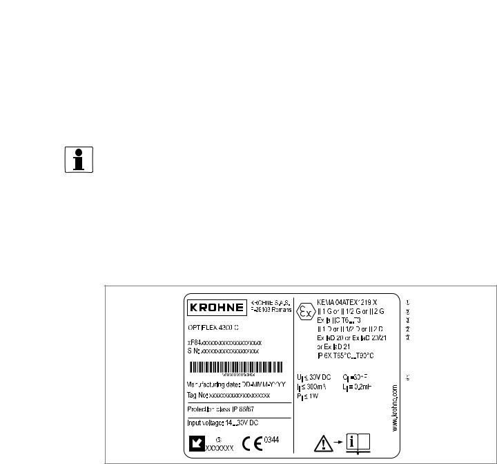
1.5 ATEX nameplates
Figure 1-1: Ex ia nameplate (device without external sensor)
1ATEX certification agency code. Refer also to temperature classes.
2Equipment approval categories
3Types of device protection including approved Gas Groups (IIA, IIB or IIC) and temperature classes for hazardous areas and maximum surface temperature (please refer to the certificate)
4Intrinsically-safe circuit data
5Cable entry type and size (Aluminium housing: M26 x 1.5, M20 x 1.5, ½NPT or G½; Stainless steel housing: M25 x 1.5, M20 x 1.5, ½NPT or G½)
|
02/2009 — 4000523601 — AD ATEX OPTIFLEX 4300 R01 en |
www.krohne.com |
5 |

|
1 GENERAL SAFETY INFORMATION |
|||||||||||||||||||
|
OPTIFLEX 4300 C |
|||||||||||||||||||
Figure 1-2: Ex ia nameplate (device with external sensor)
Figure 1-3: Ex d[ia] nameplate
1ATEX certification agency code. Refer also to temperature classes.
2Equipment approval categories
3Types of device protection including approved Gas Groups (IIA, IIB or IIC) and temperature classes for hazardous areas and maximum surface temperature (please refer to the certificate)
4Intrinsically-safe circuit data
5Maximum voltage in accordance with EN 60079-0
6Minimum waiting time after power-off before it is safe to open the terminal compartment
7Cable entry type and size (Aluminium housing: M26 x 1.5, M20 x 1.5, ½NPT or G½; Stainless steel housing: M25 x 1.5, M20 x 1.5, ½NPT or G½)
|
6 |
www.krohne.com |
02/2009 — 4000523601 — AD ATEX OPTIFLEX 4300 R01 en |
|
INSTALLATION 2 |
||
|
OPTIFLEX 4300 C |
||
2.1 Precautions
2.1.1 General notes
WARNING!
When you install the device, obey the conditions in the EC-Type Examination certificate. These conditions include:
•The special conditions for safe use.
•The Essential Health and Safety Requirements.
DANGER!
This installation must agree with EN 60079-14: Electrical installations in hazardous areas.
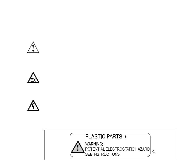
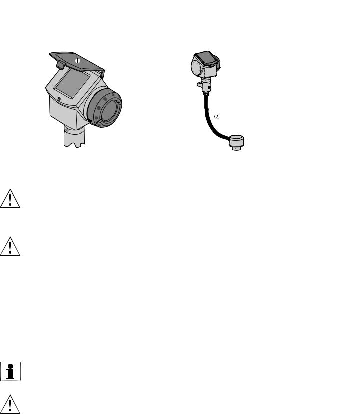
2.1.2 Electrostatic discharge
DANGER!
Risk of electrostatic discharge from the blue plastic sun cover, the conduit of the remote housing option and the optional plastic protective sheath for the single rod probe. Make sure that all personnel and equipment are correctly grounded.
Figure 2-1: ESD warning sticker (below the device nameplate)
1Text: Plastic Parts
2Text: Warning! Potential electrostatic hazard — see instructions
Take the necessary antistatic precautions if you:
•handle,
•install or
•use
the device in potentially explosive atmospheres. Do not install in a location (near to ventilation systems, for example) where the electrostatic charge can increase.
|
02/2009 — 4000523601 — AD ATEX OPTIFLEX 4300 R01 en |
www.krohne.com |
7 |
|
2 INSTALLATION |
||||
|
OPTIFLEX 4300 C |
||||
Figure 2-2: Risk of ESD: sun cover and remote housing conduit
1Sun cover
2Conduit of the remote housing option
WARNING!
FEP-coated single cable probes are for Gas group IIB only.
2.1.3 Special conditions
WARNING!
Aluminium housing: Possible source of ignition in a potentially explosive atmosphere. The housing is made of either aluminium alloy or stainless steel. If the device has an aluminium alloy housing, make sure that iron/steel objects do not hit or rub against the device.
2.2 Operating conditions
The allowable ambient temperature and corresponding flange temperature range for the device depends on the ATEX equipment category and temperature classes marked on the nameplate.
2.2.1 Ambient and flange temperature
The ATEX equipment category and temperature class give the ambient temperature and related flange temperature ranges for the device.
INFORMATION!
The remote converter and Metaglas® options use the values that follow.
WARNING!
The gasket temperature must not be more or less than the approved limits.
|
8 |
www.krohne.com |
02/2009 — 4000523601 — AD ATEX OPTIFLEX 4300 R01 en |

|
INSTALLATION 2 |
||
|
OPTIFLEX 4300 C |
||
Equipment category II 1 G (Ex ia devices only)
|
Temperature class |
Ambient temperature |
Flange temperature |
||
|
[°C] |
[°F] |
[°C] |
[°F] |
|
|
T6 |
-20…+60 |
-4…+140 |
-20…+60°C |
-4…+140 |
Equipment category II 1/2 G
|
Temperature class |
Ambient temperature |
Flange temperature |
||
|
[°C] |
[°F] |
[°C] |
[°F] |
|
|
T6 |
-40…+60 |
-40…+140 |
-20…+60°C |
-4…+140 |
|
T5 |
-40…+75 |
-40…+167 |
-20…+60°C |
-4…+140 |
|
T4 |
-40…+85 |
-40…+185 |
-20…+60°C |
-4…+140 |
Equipment category II 2 G: Ø2 mm/Ø0.08¨ single cable probe (HT, HP and HT/HP versions)
|
Temperature |
Ambient temperature |
Flange temperature |
|||||
|
class |
|||||||
|
Ø2 mm/Ø0.08¨ single cable |
Ø2 mm/Ø0.08¨ single cable |
[°C] |
[°F] |
||||
|
probe (HT version) |
probe (other versions) |
||||||
|
[°C] |
[°F] |
[°C] |
[°F] |
||||
|
T6 |
-40…+60 |
-40…+140 |
-40…+60 |
-40…+140 |
-50…+60 1 |
-58…+140 2 |
|
|
-40…+56 |
-40…+133 |
-40…+52 |
-40…+126 |
-50…+85 1 |
-58…+185 2 |
||
|
T5 |
-40…+75 |
-40…+167 |
-40…+75 |
-40…+167 |
-50…+75 |
1 |
-58…+167 2 |
|
-40…+71 |
-40…+160 |
-40…+67 |
-40…+153 |
-50…+100 1 |
-58…+212 2 |
||
|
T4 |
-40…+85 |
-40…+185 |
-40…+85 |
-40…+185 |
-50…+85 |
1 |
-58…+185 2 |
|
-40…+80 |
-40…+176 |
-40…+77 |
-40…+170 |
-50…+110 1 |
-58…+230 2 |
||
|
-40…+77 |
-40…+170 |
-40…+70 |
-40…+158 |
-50…+135 1 |
-58…+275 2 |
||
|
T3 |
-40…+75 |
-40…+165 |
-40…+65 |
-40…+149 |
-50…+150 1 |
-58…+302 2 |
|
|
-40…+71 |
-40…+160 |
— |
— |
-50…+180 1 |
-58…+356 2 |
||
|
-40…+69 |
-40…+157 |
— |
— |
-50…+200 1 |
-58…+392 2 |
||
|
T2 |
-40…+62 |
-40…+144 |
— |
— |
-50…+250 1 |
-58…+482 2 |
|
|
-40…+55 |
-40…+131 |
— |
— |
-50…+300 |
1 |
-58…+572 2 |
|
1-50°C, if an EPDM gasket is used. -40°C, if a Viton® GLT gasket is used. -20°C, if a Kalrez® 6375 gasket is used.
2-58°F, if an EPDM gasket is used. -40°F, if a Viton® GLT gasket is used. -4°F, if a Kalrez® 6375 gasket is used.
|
02/2009 — 4000523601 — AD ATEX OPTIFLEX 4300 R01 en |
www.krohne.com |
9 |
OPTIFLUX 4300 представляет собой электромагнитный расходомер (ЭМР) для агрессивных или абразивных сред в применениях с повышенными требованиями. Высокопроизводительный расходомер особенно подходит для критически важных применений с требованиями по высокой точности измерений и наличием различных диагностических функций. Он позволяет проводить надёжные измерения в том числе при очень сложных рабочих условиях с температурой до +180°C / +356°F, низкой проводимостью (≥1 мкСм/см), высоким содержанием твёрдых включений (до 70%) и высоким давлением (до 1500 бар / 21751 фунт/кв.дюйм). Для применений в целях коммерческого учёта OPTIFLUX 4300 предлагает сертификацию в соответствии с различными стандартами, в том числе OIML R49 и R117 или MI-001 и MI-005. Он также может использоваться для измерения расхода сред в системах теплоснабжения с требованиями по наличию сертификации MI-004.
Свойства продукта и опции зависят от конфигурации прибора: Просьба обратиться к нам для проверки возможности комбинирования выбранных опций в одном устройстве.
- Широкий динамический диапазон измерения расхода в обоих направлениях (диапазон регулирования 1000:1)
- Доступен с запатентованной технологией виртуального заземления: необходимость использования заземляющих колец отсутствует
- Всесторонняя диагностика расходомера и технологического процесса (включая NE 107)
- Для взрывоопасных зон: ATEX, IECEx, NEPSI, FM, CSA, EAC, INMETRO
- Стандартная погрешность измерения: ±0,2% или ±1 мм/с от измеренного значения (ИЗ)
- Для коммерческого учёта: OIML R49, OIML R-117; MI-001, MI-004, MI-005
- Футеровка из ПТФЭ, ПФА, ЭТФЭ, твёрдой резины, мягкой резины или полиуретана: превосходная устойчивость к химическому и абразивному воздействию
- Широкий выбор материалов для электродов
- Специальные конструкции, типоразмеры, внутренние диаметры и толщины футеровки по запросу
- Опционально доступные наружные покрытия для работы в морских условиях или для установки под землёй (также в соответствии с ISO 12944)
- Конструкция с полнопроходным сечением трубы: отсутствие подвижных частей, износа и потерь давления
- Поверка расходомера по месту эксплуатации с помощью диагностического устройства OPTICHECK
General advice on safety
Disclaimer
Product liability
and warranty
•
Do not install, operate or maintain this device without reading, understanding and following the factory-supplied
instructions, otherwise injury or damage may result.
•
Read these instructions carefully before starting installation and save them for future reference.
•
Observe all warnings and instructions marked on the device.
•
Use only mains supply with protective earthing connected.
•
Do not use the device with covers removed under wet conditions.
•
Follow the handling and lifting instructions to avoid damage.
•
Install the device securely and stable.
•
Install and connect cabling properly to prevent damage or harmful situations.
•
If the product does not operate normally, refer to the service instructions or consult a qualified KROHNE service
engineer. There are no operator-serviceable parts inside the product.
Danger: Risk of electric shock!
Protective Earth (PE) conductor terminal!
These terms may appear in this manual or on the instrument:
Warning statement: Identify conditions or practice that could result in injury or loss of life.
or
Caution statement: Identify conditions or practice that could result in damage to the instrument or other property.
•
This document contains important information on the device. KROHNE attempts to be as accurate and up-to-date
as possible but assumes no responsibility for errors or omissions. Nor does KROHNE make any commitment to
update the information contained herein. This manual and all other documents are subject to change without prior
notice.
•
KROHNE will not be liable for any damage of any kind by using this device, including, but not limited to direct,
indirect, incidental, punitive and consequential damages.
•
This disclaimer does not apply in case KROHNE has acted on purpose or with gross negligence. In the event any
applicable law does not allow such limitations on implied warranties or the exclusion of limitation of certain
damages, you may, if such law applies to you, not be subject to some or all of the above disclaimer, exclusions or
limitations.
•
Any device purchased from KROHNE is warranted in accordance with the relevant product documentation and our
Terms and Conditions of Sale.
•
KROHNE reserves the right to alter the content of its documents, including this disclaimer in any way, at any time,
for any reason, without prior notification, and will not be liable in any way for possible consequences of such
changes.
•
Responsibility for suitability and intended use of this device rests solely with the user. Improper installation and
operation of the device may lead to loss of warranty.
•
In addition, the Terms and Conditions of Sale are applicable and are the basis for the purchase contract.
•
If a device needs to be returned to KROHNE, please note the information given at the back of the installation and
operating instructions. KROHNE regrets that they cannot repair or check a device unless accompanied by the
completed form (see back pages of the installation and operating instructions).
Hazardous area supplement to the QuickStart
OPTIFLUX