- Manuals
- Brands
- Siemens Manuals
- Control Unit
- DESIGO PXM20
- User manual
-
Contents
-
Table of Contents
-
Bookmarks
Quick Links
s
DESIGO PX
PXM20 / PXM20-E operator unit
User’s guide
Version 2.2 and later
CM110754en_02
17 Dec 2009
Building Technologies
Related Manuals for Siemens DESIGO PXM20
Summary of Contents for Siemens DESIGO PXM20
-
Page 1
DESIGO PX PXM20 / PXM20-E operator unit User’s guide Version 2.2 and later CM110754en_02 Building Technologies 17 Dec 2009… -
Page 2: Table Of Contents
3.2.16 Domain ID (PXM20 only)……….25 3.2.17 Network scope…………. 25 Login and log-out …………26 Connecting to the network ………. 26 Login…………….27 Logout …………….. 28 2/70 Siemens PXM20 / PXM20-E operator unit CM110754en_02 Building Technologies Contents 17 Dec 2009…
-
Page 3
List view…………… 57 Service support …………58 11.1 (Wiring test) …………..58 11.2 The Wink command ………… 61 11.3 Debug information …………62 Index ………………63 3/70 Siemens PXM20 / PXM20-E operator unit CM110754en_02 Building Technologies Contents 17 Dec 2009… -
Page 4: Revision History
The following trade names and product names are registered trademarks: BACnet American National Standard (ANSI/ASHRAE 135- 1995) ® Echelon Corporation, San Jose, USA ORKS LonTalk® 4/70 Siemens PXM20 / PXM20-E operator unit CM110754en_02 Building Technologies Revision history 17 Dec 2009…
-
Page 5: About This Manual
Important For this reason, the descriptions in this manual are intended as examples, designed to clarify the basic operating principles of the PXM20 operator unit. 5/70 Siemens PXM20 / PXM20-E operator unit CM110754en_02 Building Technologies About this manual 17 Dec 2009…
-
Page 6: Printing Conventions
Important Particular attention should be paid to text marked with this symbol. Note A note qualifies an immediately preceding statement or statements. 6/70 Siemens PXM20 / PXM20-E operator unit CM110754en_02 Building Technologies About this manual…
-
Page 7: Display And Control Elements
When the view restriction option is On, the red Alarm LED lights up in the event of an alarm even if you are not logged in. Exception The LED does not flash in response to an event. 7/70 Siemens PXM20 / PXM20-E operator unit CM110754en_02 Building Technologies Display and control elements…
-
Page 8: Audible Signal
Page Down are used to indicate that there is too much text to display at once. Scroll up and down with these keys to display the whole text. 8/70 Siemens PXM20 / PXM20-E operator unit CM110754en_02 Building Technologies Display and control elements…
-
Page 9
(e.g. the editing of a value), change over to the dialog box of the next higher level or close a pop-up window. . Holding down ESC for more than 2 seconds («Long ESC») closes all the active pop-up windows. 9/70 Siemens PXM20 / PXM20-E operator unit CM110754en_02 Building Technologies Display and control elements… -
Page 10
Figure 2-2 Figure 2-3 Example: «Setpoint for cooling» Pressing the <?> key again displays a dialog box with general information about the associated window. 10/70 Siemens PXM20 / PXM20-E operator unit CM110754en_02 Building Technologies Display and control elements 17 Dec 2009… -
Page 11: Display
The example above shows page 1 of 2 of the dialog box for the Air handling unit. 11/70 Siemens PXM20 / PXM20-E operator unit CM110754en_02 Building Technologies Display and control elements…
-
Page 12: Operator Field
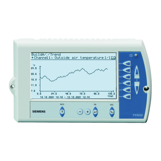
An arrowhead symbol, for values which you can edit. Graphics Trends and heating curves are displayed in graph form. Figure 2-5 Trends graph 12/70 Siemens PXM20 / PXM20-E operator unit CM110754en_02 Building Technologies Display and control elements 17 Dec 2009…
-
Page 13
Dialog boxes containing the relevant information are also displayed when you press the <?> key. Figure 2-7 Dialog box with confirmation prompt 13/70 Siemens PXM20 / PXM20-E operator unit CM110754en_02 Building Technologies Display and control elements… -
Page 14: Symbols
Operating parameters Value object Interface variable Calendar / Calendar entry Trend Time schedules Set date and time User-defined system settings Alarming & functions 14/70 Siemens PXM20 / PXM20-E operator unit CM110754en_02 Building Technologies Display and control elements 17 Dec 2009…
-
Page 15
Add new users Delete user Change password Device (Primary Server) Device (Backup Server) Wiring test (service engineers only) Wink Debug information (service engineers only) 15/70 Siemens PXM20 / PXM20-E operator unit CM110754en_02 Building Technologies Display and control elements 17 Dec 2009… -
Page 16
Reset alarm or event in Alarm & event history Symbols Description Status Work in progress Override (manually overwritten value) Life safety Plant security Fault Override active Out of service Delay Switch 16/70 Siemens PXM20 / PXM20-E operator unit CM110754en_02 Building Technologies Display and control elements 17 Dec 2009… -
Page 17: Settings
Open Alarming & functions for the current site. This is where you will find all the entries which you use to modify settings in the system using your PXM20 operator unit. Figure 3-2 Alarming & functions 17/70 Siemens PXM20 / PXM20-E operator unit CM110754en_02 Building Technologies Settings…
-
Page 18: System
The basic settings are the last Sunday in March at 0200 hours for the start of summer time and the last Sunday in October at 0300 hours for the end of summer time. 18/70 Siemens PXM20 / PXM20-E operator unit CM110754en_02 Building Technologies…
-
Page 19: Pxm20 Operator Unit
2. Select the required entry; the value will start flashing. 3. Configure the value as required. 4. Always save the new settings and restart the PXM20 operator unit. 19/70 Siemens PXM20 / PXM20-E operator unit CM110754en_02 Building Technologies Settings 17 Dec 2009…
-
Page 20: Language
BACnet communications between the different IP segments (separated by IP routers). The PXM20-E from another IP segment can register itself with BBMD as a foreign device. This 20/70 Siemens PXM20 / PXM20-E operator unit CM110754en_02 Building Technologies Settings…
-
Page 21: View Restriction
Select the devices you want to be able see for your work, and set them to Visible (Figure 3-9). Note It is recommended that the Primary Device also be set to Visible. 21/70 Siemens PXM20 / PXM20-E operator unit CM110754en_02 Building Technologies Settings…
-
Page 22: Date And Time Format
3.2.4 Date and time format Select either the American or the European date and time format. 3.2.5 Contrast The display contrast can be set here: 22/70 Siemens PXM20 / PXM20-E operator unit CM110754en_02 Building Technologies Settings 17 Dec 2009…
-
Page 23: Display Long Texts
Display saver on This option lets you define the time period (from 5 to 60 minutes in 5- minute increments) after which the display saver is to switch on. 23/70 Siemens PXM20 / PXM20-E operator unit CM110754en_02 Building Technologies Settings…
-
Page 24: Main Value
Only a subset of the standard properties, as in the BACnet standard, is displayed. In the context of PXM20 and PXM20-E, the term «third-party» or «devices from third-party manufacturers» is used to refer to «non-PX devices». 24/70 Siemens PXM20 / PXM20-E operator unit CM110754en_02 Building Technologies Settings 17 Dec 2009…
-
Page 25: Domain Id (Pxm20 Only)
BACnet devices connected to the same network, or also with BACnet devices connected to another BACnet network. Important This setting should be modified only by fully trained staff. 25/70 Siemens PXM20 / PXM20-E operator unit CM110754en_02 Building Technologies Settings 17 Dec 2009…
-
Page 26: Login And Log-Out
The login procedure is in two steps: 1. Select a site If no sites are listed, this means that no automation station in the network has been defined as the primary server. 26/70 Siemens PXM20 / PXM20-E operator unit CM110754en_02 Building Technologies Login and log-out…
-
Page 27: Login
Logging in to Before you can log in to a new site, you must first log out from the another site current site (see the next section). 27/70 Siemens PXM20 / PXM20-E operator unit CM110754en_02 Building Technologies Login and log-out…
-
Page 28: Logout
1. Within the site, go to Alarming & functions. Logout 2. Select Logout. 3. Confirm that you really do want to log out. 4. The site overview appears again (Figure 3-1). 28/70 Siemens PXM20 / PXM20-E operator unit CM110754en_02 Building Technologies Login and log-out 17 Dec 2009…
-
Page 29: Navigation
If there are several pages in one display, use the Page Up and Page Down keys to change to the next or previous page. The total number to page of pages is shown in the top right corner of the display: 29/70 Siemens PXM20 / PXM20-E operator unit CM110754en_02 Building Technologies Navigation…
-
Page 30: Reading And Editing Values
To keep the manual as clear as possible, the instruction «Press the direct access key» is not repeated. Example: «Select the month and the year». 30/70 Siemens PXM20 / PXM20-E operator unit CM110754en_02 Building Technologies Reading and editing values…
-
Page 31: Example: Setting A Setpoint
Example: Setting a setpoint Navigate to the value that you want to edit. Set the required value. Figure 6-2 Setting a manual setpoint 31/70 Siemens PXM20 / PXM20-E operator unit CM110754en_02 Building Technologies Reading and editing values 17 Dec 2009…
-
Page 32: Example: Editing The Heating Curve
Select LIST VIEW for access to a list of all parameters, inputs and curve outputs. Figure 6-4 Heating curve: list view, page 1 32/70 Siemens PXM20 / PXM20-E operator unit CM110754en_02 Building Technologies Reading and editing values 17 Dec 2009…
-
Page 33: Forced Control
You can use the direct access key to cancel the forced control in the dialog box again. The forced control symbol is displayed after the input or output has Forced control been forced. symbol 33/70 Siemens PXM20 / PXM20-E operator unit CM110754en_02 Building Technologies Reading and editing values 17 Dec 2009…
-
Page 34: Alarms
The display shows a time stamp, the object name, the notification text and the alarm priority. In the case of alarm messages, you can display the Alarm viewer directly (see Section 7.2.1). 34/70 Siemens PXM20 / PXM20-E operator unit CM110754en_02 Building Technologies…
-
Page 35: Alarm Acknowledgement
You can go to the Alarm viewer either from the Alarming & functions window, or display it directly from the alarm pop-up. Figure 7-2 Alarm viewer 35/70 Siemens PXM20 / PXM20-E operator unit CM110754en_02 Building Technologies Alarms 17 Dec 2009…
-
Page 36: Selecting An Event Or Alarm
6. You can now select either ACKNOWLEDGE or DETAILS. The procedure for events is basically the same as for alarms. Unlike alarms, however, you do not need to acknowledge events. 36/70 Siemens PXM20 / PXM20-E operator unit CM110754en_02 Building Technologies…
-
Page 37: Alarm Acknowledgement / Alarm & Event Details
OBJECT PROPERTIES lets you navigate directly to the alarm source. Press ESC to return to the Alarm viewer. Your user access rights will determine whether or not you have Note access to Object properties. 37/70 Siemens PXM20 / PXM20-E operator unit CM110754en_02 Building Technologies Alarms 17 Dec 2009…
-
Page 38: Alarm & Event History
The following information is displayed for a maximum of 30 entries: All the most recently received alarms The most recent alarm acknowledgements The most recent events 38/70 Siemens PXM20 / PXM20-E operator unit CM110754en_02 Building Technologies Alarms…
-
Page 39
As with Alarm viewer, you can invoke an individual alarm or event here, and view the details. Symbols in the Alarm & event history Unacknowledged alarm Normal state, existing alarm unacknowledged System event Acknowledged Reset 39/70 Siemens PXM20 / PXM20-E operator unit CM110754en_02 Building Technologies Alarms 17 Dec 2009… -
Page 40: Access Rights
Members of a group are authorized to add new users to groups at a lower hierarchical level. Within the current site, go to Alarming & functions and select User definition 2 Select Add new user 40/70 Siemens PXM20 / PXM20-E operator unit CM110754en_02 Building Technologies Access rights 17 Dec 2009…
-
Page 41
Select initials for the user you have defined 9 Answer the prompt to save the new user entry: SAVE USER The display will revert to the User definition dialog box 41/70 Siemens PXM20 / PXM20-E operator unit CM110754en_02 Building Technologies Access rights… -
Page 42: Remove User
Select the user, for which you want to edit the data. Make the required changes and confirm them by selecting SAVE USER. 42/70 Siemens PXM20 / PXM20-E operator unit CM110754en_02 Building Technologies Access rights…
-
Page 43: Setting Time Schedules
A graphics-based display of the selected day appears on the second line. You can select the individual switching points with the associated direct access key. The next line displays the values for the selected switching point. 43/70 Siemens PXM20 / PXM20-E operator unit CM110754en_02 Building Technologies Setting time schedules…
-
Page 44: Editing The Switching Points
To add an entry select NEW ENTRY and edit the new entry. 9.1.1.4 Delete entry To delete an entry, first select the entry to be deleted, and then select DELETE ENTRY. 44/70 Siemens PXM20 / PXM20-E operator unit CM110754en_02 Building Technologies Setting time schedules 17 Dec 2009…
-
Page 45: Exception Schedule
Select the required day and confirm with OK. A list of all the exceptions for the selected day is displayed. You can edit this display directly. 45/70 Siemens PXM20 / PXM20-E operator unit CM110754en_02 Building Technologies Setting time schedules…
-
Page 46: Listing All The Exceptions
Schedule exception list (Figure 9-3). The next section describes how to adapt this exception to your own particular needs. 46/70 Siemens PXM20 / PXM20-E operator unit CM110754en_02 Building Technologies Setting time schedules…
-
Page 47: Editing A Local Exception
Select EDIT PROFILE for access to the 24-hour profile of an exception. In this dialog box, you can select whether you want to modify the program or to delete all entries. 47/70 Siemens PXM20 / PXM20-E operator unit CM110754en_02 Building Technologies…
-
Page 48
All entries will be deleted from the system. This button is used to delete the selected exception. Use this button to revert to the Schedule exception list, Figure 9-3). 48/70 Siemens PXM20 / PXM20-E operator unit CM110754en_02 Building Technologies Setting time schedules… -
Page 49: Edit Calendar Object
When editing calendar entries, extreme caution is advised, as this STOP can sometimes affect the exception programs of other time schedules. 49/70 Siemens PXM20 / PXM20-E operator unit CM110754en_02 Building Technologies Setting time schedules 17 Dec 2009…
-
Page 50: Trend Function And Settings
(Figure 10-3). Section 10.3 describes how to set the trend parameters and define the type of view required.<0} The data point is automatically assigned to the first free channel. 50/70 Siemens PXM20 / PXM20-E operator unit CM110754en_02 Building Technologies Trend function and settings…
-
Page 51: Displaying An Existing Trend
The next section describes how to set the trend parameters and define the type of view required. This button allows you to stop all trend logging and delete all configured trend charts. 51/70 Siemens PXM20 / PXM20-E operator unit CM110754en_02 Building Technologies Trend function and settings…
-
Page 52: Main Trend Dialog Box
From the main trend dialog box (Figure 10-3) select Trend configuration . You can now modify the parameters for the required trend logging. Figure 10-4 Configuration, pages 1 and 2 52/70 Siemens PXM20 / PXM20-E operator unit CM110754en_02 Building Technologies Trend function and settings…
-
Page 53
(start time, stop time and referenced data point). You can display the trend data in three different views, as described in the next section. 53/70 Siemens PXM20 / PXM20-E operator unit CM110754en_02 Building Technologies Trend function and settings… -
Page 54: Graphic View
Use Compare with channel to compare the selected trend with another trend you have set up (see Figure 10-9). Select GRAPHIC to confirm your settings and display the trend. 54/70 Siemens PXM20 / PXM20-E operator unit CM110754en_02 Building Technologies Trend function and settings…
-
Page 55
Figure 10-7 Graphic view with two channels Setting guides A guide line can be set and moved by use of the <+> and <-> keys. The data display is also refreshed. 55/70 Siemens PXM20 / PXM20-E operator unit CM110754en_02 Building Technologies Trend function and settings… -
Page 56: Graphic View Online
The trend is displayed soon as you confirm your entries via GRAPHIC. You can reset the graphic display by pressing OK. Figure 10-9 Online trend 56/70 Siemens PXM20 / PXM20-E operator unit CM110754en_02 Building Technologies Trend function and settings 17 Dec 2009…
-
Page 57: List View
List view Instead of displaying the logged values in graph form, you can view them in list form. Figure 10-10 Trend values in the list view 57/70 Siemens PXM20 / PXM20-E operator unit CM110754en_02 Building Technologies Trend function and settings…
-
Page 58: Service Support
Go to Alarming & functions and choose Wiring test. – Follow the instructions in the display, and press the service pin of the required automation station. 58/70 Siemens PXM20 / PXM20-E operator unit CM110754en_02 Building Technologies Service support 17 Dec 2009…
-
Page 59
RUN STA ERR TX SERVICE TX SERVICE Servicepin for IP devices Figure 11-3 Position of the service pin in a PX modular automation station The wiring test is carried out. 59/70 Siemens PXM20 / PXM20-E operator unit CM110754en_02 Building Technologies Service support 17 Dec 2009… -
Page 60
The use of this IP address is not checked. If the wiring test is carried out on a different PXM20-E operator unit, a master reset of the automation is required before you start. 60/70 Siemens PXM20 / PXM20-E operator unit CM110754en_02 Building Technologies… -
Page 61: The Wink Command
The identification process is carried out with the Wink command. Figure 11-5 The “Wink” command To send the Wink command, select Send service pin message. This immediately triggers the Wink signal. Figure 11-6 61/70 Siemens PXM20 / PXM20-E operator unit CM110754en_02 Building Technologies Service support 17 Dec 2009…
-
Page 62: Debug Information
The time at which the error occurred. The format is as follows: occurrence Day, month, minute, second and millisecond since 01.01.1970 00:00. Example: 11801 DAYS 09:25:06.000 62/70 Siemens PXM20 / PXM20-E operator unit CM110754en_02 Building Technologies Service support 17 Dec 2009…
-
Page 63: Index
Alarm pop-up …………….23, 34 Alarm text mode…………….23 Alarm viewer ………………35 Alarming & functions…………..17, 28 Audible signal …………….8, 23, 34 Buzzer………………..23 Cancel audible signal……………35 CHANGE DATE…………….47 CHANGE PROGRAM…………..44 63/70 Siemens PXM20 / PXM20-E operator unit CM110754en_02 Index 17 Dec 2009 Building Technologies…
-
Page 64
Delete ………………44 New ………………..44 ESC key………………6, 9 Event DETAILS………………37 Events………………..34 Select………………36 Exception list Edit Calendar object …………..49 EXCEPTION OVERVIEW…………..45 Exception program EXCEPTION OVERVIEW …………45 Exception schedule…………….45 64/70 Siemens PXM20 / PXM20-E operator unit CM110754en_02 Index 17 Dec 2009 Building Technologies… -
Page 65
LED………………..7, 34 LIST VIEW Heating curve …………….32 List view, online trend …………..57 LOG DATA POINT…………….50 Log in and log out …………….26 Login ………………..27 START ………………26 Logout………………..28 65/70 Siemens PXM20 / PXM20-E operator unit CM110754en_02 Index 17 Dec 2009 Building Technologies… -
Page 66
Schedule exception list …………..45 CHANGE DATE…………….47 DELETE ENTRY …………….48 EDIT PROFILE …………….47 NEW LOCAL EXCEPTION…………46 SAVE & EXIT…………….48 Schedule exception list: …………..49 Scheduler………………43 Service pin ……………..58, 59 66/70 Siemens PXM20 / PXM20-E operator unit CM110754en_02 Index 17 Dec 2009 Building Technologies… -
Page 67
Favorites ………………14 Forced control…………….33 Global objects…………….15 Hierarchical element…………..14 Information………………14 Input………………..14 Interface variable …………….14 Log-out ………………14 Navigate ………………14 Output ………………14 Override ………………16 Parameters ……………..14 Power control…………….14 Reset ………………39 67/70 Siemens PXM20 / PXM20-E operator unit CM110754en_02 Index 17 Dec 2009 Building Technologies… -
Page 68
RELEASE ALL CHANNELS …………51 RELEASE CHANNEL…………..52 SAVE TREND SETTINGS…………53 Set up new trend …………….50 Start time ………………53 Stop time ………………53 Stop when full …………….53 Views ………………50 Trend configuration…………….52 68/70 Siemens PXM20 / PXM20-E operator unit CM110754en_02 Index 17 Dec 2009 Building Technologies… -
Page 69
Force ………………33 Reading and writing…………..30 View Graphic ………………32 List view………………32 Welcome window…………….24 Wildcards ………………27 Wiring test………………58 List of inputs and outputs…………60 WIRING TEST ……………..27 Write access ………………40 69/70 Siemens PXM20 / PXM20-E operator unit CM110754en_02 Index 17 Dec 2009 Building Technologies… -
Page 70
Industry Sector Building Technologies Division International Headquarters Gubelstrasse 22 CH-6301 Zug Tel. +41 41-724 24 24 Fax +41 41-724 35 22 © 2003 — 2009 Siemens Switzerland Ltd www.buildingtechnologies.siemens.com Subject to change 70/70 Siemens PXM20 / PXM20-E operator unit CM110754en_02…
2/70
Siemens
Building Technologies
Contents
Revision history……………………………………………………………………. 4
1
About this manual ………………………………………………. 5
1.1
Target readers……………………………………………………… 5
1.2
Contents ……………………………………………………………… 5
1.3
1.3.1
Text ……………………………………………………………………. 6
1.3.2
Keys …………………………………………………………………… 6
1.3.3
Notes ………………………………………………………………….. 6
2
2.1
Housing ………………………………………………………………. 7
2.1.1
Alarm LED …………………………………………………………… 7
2.1.2
Audible signal ………………………………………………………. 8
2.1.3
Keys …………………………………………………………………… 8
2.2
Display………………………………………………………………. 11
2.2.1
Title bar …………………………………………………………….. 11
2.2.2
Operator field……………………………………………………… 12
2.2.3
Symbols…………………………………………………………….. 14
3
Settings ……………………………………………………………. 17
3.1
System ……………………………………………………………… 18
3.1.1
3.1.2
Daylight savings …………………………………………………. 18
3.2
3.2.1
Language ………………………………………………………….. 20
3.2.2
3.2.3
View restriction …………………………………………………… 21
3.2.4
3.2.5
Contrast…………………………………………………………….. 22
3.2.6
Display long texts ……………………………………………….. 23
3.2.7
Buzzer ………………………………………………………………. 23
3.2.8
Alarm pop-up……………………………………………………… 23
3.2.9
Event Pop-up……………………………………………………… 23
3.2.10
Alarm text mode …………………………………………………. 23
3.2.11
Relogin ……………………………………………………………… 23
3.2.12
Display saver on…………………………………………………. 23
3.2.13
Main value …………………………………………………………. 24
3.2.14
Welcome window ……………………………………………….. 24
3.2.15
Third-party site …………………………………………………… 24
3.2.16
3.2.17
Network scope……………………………………………………. 25
4
Login and log-out ……………………………………………… 26
4.1
4.2
Login…………………………………………………………………. 27
4.3
Logout ………………………………………………………………. 28
PXM20 / PXM20-E operator unit
Contents
CM110754en_02
17 Dec 2009
Siemens DESIGO PXM20 Control Unit PDF User Guides and Manuals for Free Download: Found (1) Manuals for Siemens DESIGO PXM20 Device Model (Operation & User’s Manual)
More Control Unit Device Models:
-
Xpresskit
DBALL
Vehicle Application Guide………………………………………………………………………………………………………………………………OEM Remote Starter Detection…………………………………………………………………………………………………………… …
DBALL Automobile Accessories, 20
-
Siemens
SINUMERIK 802D
SINUMERIK SINUMERIK 802D sl Cylindrical grinding __________________________________________________________________________________________________________________________________________________________________________________________________________________Preface Description 1 Software interface 2 Turning on, ref …
SINUMERIK 802D Control Unit, 399
-
LSIS
SV-iS7 series
User Manual ● Read this manual carefully before installing, wiring, operating, servicing or inspecting this equipment.● Keep this manual within easy reach for quick reference.Right choice for ultimate yieldLSIS strives to maximize customers’ profit in gratitude of choosing us for your partner.Pulse …
SV-iS7 series Recording Equipment, 22
-
Lite-Puter
CX-12II
ISO 9001 CERTIFIED www.liteputer.com.tw Lite-Puter CX-12 [EUM-E] CX-12II DMX 96 Control Channel Dimming Controller 【User Manual】 Lite-Puter Enterprise Co., Ltd. Website: www.liteputer.com.tw E-mail: [email protected] www.bluelight.at …
CX-12II Control Unit, 22
Recommended Documentation:
PXM20 / PXM20-E operator unit User’s guide
Karl Wellinger Siemens AG
this manual 2017-04-05 1 About this manual 1.1 Target readers This user guide is intended for those responsible for the HVAC plant in a building, and for other qualified staff, including service engineers. It is assumed that the users of the manual will have all the knowledge and skills needed to carry out the required tasks.
PXM20 / PXM20-E operator unit User’s guide — Siemens …
The manual starts with a description of the display and control panel of the PXM20 (BACnet/LonTalk) and PXM20-E (BACnet/Ethernet/IP).
PXM20 / PXM20-E operator unit User’s guide
The manual starts with a description of the display and control panel of the PXM20 … For this reason, the descriptions in this manual are intended as examples, designed to clarify…
- PDF Viewer
- Universal Document Viewer
- Google Docs View
- Google Drive View
- Download Document [pdf]Not Your Device? Search For Manuals / Datasheets:
File Info : application/pdf, 72 Pages, 1.31MB
Document
Download.aspx?pos=download&fct=getasset&id1=A6V10408410
s
Desigo PX PXM20 / PXM20-E operator unit User's guide
Version 6.1 and later
CM110754en_06 2017-04-05
Building Technologies
Contents
2/72
Siemens Building Technologies
Revision history .............................................................................4
Reference to trade names and product names ............................4
Third-Party Software Information..................................................5
1 1.1 1.2 1.3 1.3.1 1.3.2 1.3.3
About this manual......................................................6 Target readers .............................................................6 Contents ......................................................................6 Printing conventions.....................................................7 Text .............................................................................. 7 Keys ............................................................................. 7 Notes ...........................................................................7
2 2.1 2.1.1 2.1.2 2.1.3 2.2 2.2.1 2.2.2 2.2.3
Display and control elements....................................8 Housing........................................................................ 8 Alarm LED ...................................................................8 Audible signal...............................................................9 Keys ............................................................................. 9 Display ....................................................................... 12 Title bar......................................................................12 Operator field .............................................................13 Symbols .....................................................................15
3 3.1 3.1.1 3.1.2 3.2 3.2.1 3.2.2 3.2.3 3.2.4 3.2.5 3.2.6 3.2.7 3.2.8 3.2.9 3.2.10 3.2.11 3.2.12 3.2.13 3.2.14 3.2.15 3.2.16 3.2.17
Settings.....................................................................18 System ....................................................................... 19 Set time & date (system time) ....................................19 Daylight savings.........................................................19 Device ........................................................................ 20 Language ................................................................... 21 IP settings (PXM20-E only) ........................................21 View restriction...........................................................22 Date and time format..................................................23 Contrast .....................................................................23 Display long texts .......................................................24 Buzzer ....................................................................... 24 Alarm pop-up .............................................................24 Event Pop-up .............................................................24 Alarm text mode.........................................................24 Relogin....................................................................... 24 Display saver on ........................................................24 Main value .................................................................25 Welcome window .......................................................25 Third-party site ...........................................................25 Domain ID (PXM20 only)............................................26 Network scope ...........................................................26
4
Login and log-out.....................................................28
4.1
Connecting to the network..........................................28
4.2
Login .......................................................................... 29
PXM20 / PXM20-E operator unit Contents
CM110754en_06 2017-04-05
4.3
5
6 6.1 6.2 6.3
7 7.1 7.2 7.2.1 7.2.2 7.2.3 7.3
8 8.1 8.2 8.3 8.4 8.5 8.6
9 9.1 9.1.1 9.2 9.2.1 9.2.2 9.2.3 9.2.4 9.2.5
10 10.1 10.2 10.3 10.3.1 10.3.2 10.3.3 10.3.4
11 11.1 11.2 11.3
Index
Logout ........................................................................ 31
Navigation ................................................................32
Reading and editing values .....................................33 Example: Setting a setpoint........................................34 Example: Editing the heating curve ............................35 Forced control ............................................................36
Alarms....................................................................... 37 Occurrence of alarms and events...............................37 Alarm acknowledgement ............................................38 Displaying the alarm viewer........................................38 Selecting an event or alarm........................................39 Alarm acknowledgement / Alarm & Event details........40 Alarm & event history .................................................41
Access rights ...........................................................43 Introduction ................................................................43 Password ...................................................................43 Adding new users.......................................................43 Remove user..............................................................45 Change password ......................................................45 Edit user.....................................................................45
Setting time schedules ............................................46 Scheduler ................................................................... 46 Editing the switching points ........................................47 Exception schedule ....................................................48 Listing the exceptions for a given day.........................48 Listing all the exceptions ............................................49 Create new local exception ........................................50 Editing a local exception.............................................50 Edit Calendar object...................................................52
Trend function and settings ....................................53 Setting up a new trend ...............................................53 Displaying an existing trend........................................54 Main trend dialog box.................................................55 Trend configuration ....................................................55 Graphic view ..............................................................57 Graphic view online....................................................59 List view .....................................................................60
Service support........................................................61 Wiring test..................................................................61 The Wink command ...................................................64 Debug information......................................................65
.................................................................................. 66
Siemens Building Technologies
PXM20 / PXM20-E operator unit Contents
3/72
CM110754en_06 2017-04-05
Revision history
Version
V6.1
Date 04.2017
Doc. No. CM110754en_06
V5.1 08.2014 CM110754en_05
V5.1 12.2013 CM110754en_04
V5.1 V2.36
05.2013 12.2009 07.2006
CM110754en_03 CM110754en_02 CM110754en_01
V2.35 12.2005 CM110754en
Change
Third-Party Software Information Change int. password Wiring Test
Note concerning local / global communication
Functionality 5.1
Validity "2.2 and later
"Revision history", and "Reference to trade names and product names" added. New note Correction New "View restriction" feature added Amendment and addition to "Wiring test" section Minor changes to text (nomenclature) with no effect on content
First edition
Section Pages 5
4 11.1 3.2.17 All
1
2.1.1 3.2 3.2.3 11.1
Whole document
Reference to trade names and product names
The following trade names and product names are registered trademarks:
BACnet
LONWORKS® LonTalk®
American National Standard (ANSI/ASHRAE 1351995) Echelon Corporation, San Jose, USA
4/72
Siemens Building Technologies
PXM20 / PXM20-E operator unit 0BRevision history
CM110754en_06 2017-04-05
Third-Party Software Information
This product, solution or service ("Product") contains third-party software components listed in this document. These components are Open Source Software licensed under a license approved by the Open Source Initiative (www.opensource.org) or similar licenses as determined by SIEMENS ("OSS") and/or commercial or freeware software components. With respect to the OSS components, the applicable OSS license conditions prevail over any other terms and conditions covering the Product. The OSS portions of this Product are provided royalty-free and can be used at no charge.
If SIEMENS has combined or linked certain components of the Product with/to OSS components licensed under the GNU LGPL version 2 or later as per the definition of the applicable license, and if use of the corresponding object file is not unrestricted ("LGPL Licensed Module", whereas the LGPL Licensed Module and the components that the LGPL Licensed Module is combined with or linked to is the "Combined Product"), the following additional rights apply, if the relevant LGPL license criteria are met: (i) you are entitled to modify the Combined Product for your own use, including but not limited to the right to modify the Combined Product to relink modified versions of the LGPL Licensed Module, and (ii) you may reverse-engineer the Combined Product, but only to debug your modifications. The modification right does not include the right to distribute such modifications and you shall maintain in confidence any information resulting from such reverse-engineering of a Combined Product.
Certain OSS licenses require SIEMENS to make source code available, for example, the GNU General Public License, the GNU Lesser General Public License and the Mozilla Public License. If such licenses are applicable and this Product is not shipped with the required source code, a copy of this source code can be obtained by anyone in receipt of this information during the period required by the applicable OSS licenses by contacting the following address:
Siemens AG, Otto-Hahn-Ring 6 81739 Muenchen, Germany Keyword: Open Source Request
All open source software components used within the product (including their copyright holders and the license conditions) are contained on the web server, path -> http://ip_address_of_the_device/licenses/
Siemens Building Technologies
PXM20 / PXM20-E operator unit 2BThird-Party Software Information
5/72
CM110754en_06 2017-04-05
1 About this manual
1.1 Target readers
This user guide is intended for those responsible for the HVAC plant in a building, and for other qualified staff, including service engineers. It is assumed that the users of the manual will have all the knowledge and skills needed to carry out the required tasks.
1.2 Contents
Important
The manual starts with a description of the display and control panel of the PXM20 (BACnet/LonTalk) and PXM20-E (BACnet/Ethernet/IP) operator unit and presents the procedures for navigation and for editing values, which are always the same. The second part of the manual leads you step by step through the various activities involved in commissioning and maintaining the plant.
As there may be significant differences between one plant and another, and between the read and write access of one user and another, it follows that it is not possible to provide a description which is generally applicable to every individual case.
"Favorite" objects, for example, are special objects containing important values, which can be accessed with a short-cut operation. The question of exactly which objects and which values these are, is determined in the engineering phase according to the individual needs of the plant operator.
For this reason, the descriptions in this manual are intended as examples, designed to clarify the basic operating principles of the PXM20 operator unit.
6/72
Siemens Building Technologies
PXM20 / PXM20-E operator unit 3BAbout this manual
CM110754en_06 2017-04-05
Note!
STOP
1.3 Printing conventions
1.3.1 Text
Bold text is used for text exactly as it appears in the display, e.g. START, ACKNOWLEDGE, Settings etc.
1.3.2 Keys
Keys are shown as follows: · Key names that appear on the key itself are shown in angular
brackets < > This convention is used for the < ? > key (Info), and the < > and < + > keys. Example: Press the <?> key.
· The OK key and ESC key are referred to without brackets; their name is marked on the unit housing. Example: Press the ESC key or: Acknowledge with OK.
· The "direct access" keys are referred to as such. Their function is described neither on the keys themselves nor on the housing. Example: Use the direct access key to go to the next value.
· The same applies to the Page Up and Page Down keys. Example: Go to the next dialog box using the Page Down key.
1.3.3 Notes
The symbol shown here acts as a warning in cases where an action may result in permanent loss of data.
Important Particular attention should be paid to text marked with this symbol.
Note A note qualifies an immediately preceding statement or statements.
Siemens Building Technologies
PXM20 / PXM20-E operator unit 3BAbout this manual
7/72
CM110754en_06 2017-04-05
2 Display and control elements
2.1 Housing
1
2
00262
3
4
OK
ES C
?
+
PXM20
Note!
7
5
6
Figure 2-1 Housing
Key:
1. Display panel (Section 2.2) 2. Direct access keys (Section 2.1.3.1) 3. Alarm LED (Section 2.1.1) 4. Page Up & Page Down keys (Section 2.1.3.2) 5. OK key, <+> and <> editing keys (Section 2.1.3.3) 6. ESC key (Section 2.1.3.4) 7. <?> key (Section 2.1.3.5)
2.1.1 Alarm LED
When an alarm is tripped in the system, the alarm LED lights up or flashes, provided a user is logged in. As soon as all alarms have been acknowledged, the LED stops flashing and remains on continuously. For further information on alarm signals refer to Section 7.
When the view restriction option is On, the red Alarm LED lights up in the event of an alarm even if you are not logged in.
Exception
8/72 Siemens Building Technologies
The LED does not flash in response to an event.
PXM20 / PXM20-E operator unit 4BDisplay and control elements
CM110754en_06 2017-04-05
2.1.2 Audible signal
If the Buzzer is set to On under Settings (see Section 3), then any alarm requiring acknowledgement and/or a reset will be additionally accompanied by an audible signal. Alarms which do not require acknowledgement or reset are not accompanied by an audible alarm signal.
2.1.3 Keys
2.1.3.1 Direct access keys
An arrowhead symbol at the end of a line indicates that, for that line, you can use the associated direct access key to carry out a number of actions: The direct access keys have a dual function. · Navigation:
Direct access to the view at the next level down. Refer to Section 5 for detailed instructions on navigating in the PXM20. · Editing a value Your user access rights determine whether you can edit values, or only read them. Refer to Section 6 for detailed instructions on editing values in the PXM20.
2.1.3.2 Page Up and Page Down
If there are several pages in one display, use the Page Up and Page Down keys to change to the next or previous page. You can also use Page Up and Page Down in addition to the <+> and < >keys, to edit numerical values.
In pop-ups and dialog boxes, the symbols for Page Up and Page Down are used to indicate that there is too much text to display at once. Scroll up and down with these keys to display the whole text.
Siemens Building Technologies
PXM20 / PXM20-E operator unit 4BDisplay and control elements
9/72
CM110754en_06 2017-04-05
2.1.3.3 The OK key and the edit keys <+> and <>
As soon as you access a value with the direct access key, the value concerned begins to flash, indicating that it can be edited with the <+> and <> keys. Confirm each change by pressing OK. In addition to the <+> and <>keys you can use Page Up and Page Down to edit numerical values. The step-by-step procedure for editing is described in Section 6
2.1.3.4 ESC key
By pressing the ESC key you can cancel any current process at any time (e.g. the editing of a value), change over to the dialog box of the next higher level or close a pop-up window. .
Holding down ESC for more than 2 seconds ("Long ESC") closes all the active pop-up windows.
10/72
Siemens Building Technologies
PXM20 / PXM20-E operator unit 4BDisplay and control elements
CM110754en_06 2017-04-05
Info mode
2.1.3.5 The info key <?>
Pressing the <?> key once takes you into "Info" mode. A question mark at the end of a line indicates that you can display information associated with this line. To do this, press the associated direct access key.
Figure 2-2
Figure 2-3 Example: "Setpoint for cooling"
Pressing the <?> key again displays a dialog box with general information about the associated window.
Siemens Building Technologies
PXM20 / PXM20-E operator unit 4BDisplay and control elements
11/72
CM110754en_06 2017-04-05
2.2 Display
All the elements of a plant are shown in the display, with values or information which you can read or overwrite, depending on your user access rights. Figure 2-4 shows the layout of the display. The next section describes the areas of the display and the symbols used.
The keys used for navigation and editing are outside the display panel, and set into the housing itself. These keys are also described below in more detail.
Title bar
Line of text
Operator field
Figure 2-4 Layout of the display
2.2.1 Title bar
The current level within the tree structure is shown at the top left of the display panel; this is marked with an arrow . The current page and the total number of pages is shown on the right. The title bar is separated from the rest of the display with a horizontal line.
The example above shows page 1 of 2 of the dialog box for the Air handling unit.
12/72
Siemens Building Technologies
PXM20 / PXM20-E operator unit 4BDisplay and control elements
CM110754en_06 2017-04-05
Text lines Graphics
2.2.2 Operator field
Below the title bar is the operator field, which may contain either several lines of alphanumerical text, or a graph. A maximum of six lines of text can be displayed in the operator field. If there are more than this, the remaining lines appear on the next page.
An ellipsis (...) indicates that the text is too long to fit on the line.
To see the rest of the information, use the <?> key followed by the direct access key. Each line comprises the following elements from left to right: · Symbol · Values, alarms, events, entries, functions, hierarchical elements
etc. · An arrowhead symbol, for values which you can edit. Trends and heating curves are displayed in graph form.
Figure 2-5 Trends graph
Siemens Building Technologies
PXM20 / PXM20-E operator unit 4BDisplay and control elements
13/72
CM110754en_06 2017-04-05
Buttons Pop-up
The button-field contains other functions or dialog boxes to which you can gain access by pressing the associated direct access key. Buttons are identified by upper case text in a box.
A "pop-up" is a dialog box used to display an alarm or an event. The ALARM VIEWER button provides direct access to the list of active alarms.
Dialog box
Figure 2-6 Pop-up
After a given action, a dialog box will appear, with a prompt which must be acknowledged before the required action is carried out or cancelled. Dialog boxes containing the relevant information are also displayed when you press the <?> key.
Figure 2-7 Dialog box with confirmation prompt
14/72
Siemens Building Technologies
PXM20 / PXM20-E operator unit 4BDisplay and control elements
CM110754en_06 2017-04-05
2.2.3 Symbols
The following is a list of all the symbols used in the display, and their meanings. The same symbol may represent different entries, or have a different meaning, depending on the context.
Symbols Navigation
Description
Arrowhead. Values on this line can be accessed with the direct access key directly to the right of the line. This line contains additional information about the highlighted object. The information appears when you press the Info key <?>. Refer also to Section 2.1.3.5. Page(s) Page n of total n pages. Scroll up to display more information Scroll down to display more information
Symbols
Description Site Hierarchical element
Log-out
Favorites. These are defined in the engineering phase and contain frequently interrogated elements with simple operator access.
Group object (room automation) Command control Power control Input Output Operating parameters Value object Interface variable
Calendar / Calendar entry Trend or multiple trend 1. Time schedules 2. Set date and time
Event Enrollment Object
Siemens Building Technologies
PXM20 / PXM20-E operator unit 4BDisplay and control elements
15/72
CM110754en_06 2017-04-05
Symbols
Description Event Log Object Load Control Object User-defined system settings Alarming & functions Daylight savings Global objects. Contain data which is globally available (within a given site, across automation stations) Edit user Add new users Delete user Change password Device (Primary Server) Device (Backup Server) Program Object Wiring test (service engineers only) Wink Debug information (service engineers only)
16/72
Siemens Building Technologies
PXM20 / PXM20-E operator unit 4BDisplay and control elements
CM110754en_06 2017-04-05
Symbols Alarms & Events
Description
Symbols Status
1. Alarm overview 2. Alarm and event history: Alarm for "Off Normal" or fault state; flashing indicates unacknowledged alarm Acknowledged alarm state Alarm for "Normal" state; flashing indicates unacknowledged state. Normal state not reset System event Acknowledged alarm or event in Alarm & event history Reset alarm or event in Alarm & event history
Description
Work in progress Override (manually overwritten value)
Life safety Plant security Fault Override active Out of service Delay Switch
Siemens Building Technologies
PXM20 / PXM20-E operator unit 4BDisplay and control elements
17/72
CM110754en_06 2017-04-05
3 Settings
Notes
1. You can only carry out the settings described below if the appropriate rights have been assigned to you. These rights are allocated either in the engineering phase, or later by the system administrator.
2. To be able to carry out settings and modifications, you must be in a site (see Section 4).
Figure 3-1 Site overview Open Alarming & functions for the current site. This is where you will find all the entries which you use to modify settings in the system using your PXM20 operator unit.
Figure 3-2 Alarming & functions
18/72
Siemens Building Technologies
PXM20 / PXM20-E operator unit 5BSettings
CM110754en_06 2017-04-05
3.1 System
3.1.1 Set time & date (system time)
Note You can only make time settings if a primary server has been defined in the network. The system time is always applicable to one site. To change the system time, proceed as follows:
1. Open Alarming & functions > Set date & time for the current site.
2. Set the required time using the direct access key adjacent to the numerical time display.
3. Save the new settings.
3.1.2 Daylight savings
This option is used to define the requirements for an automatic daylight savings time change.
1. Open Alarming & functions for the current site. 2. Select Set daylight savings
3. You can start by accepting or rejecting the current automatic summer time change.
4. You then define on what date and at what time summer time is to begin and end. The basic settings are the last Sunday in March at 0200 hours for the start of summer time and the last Sunday in October at 0300 hours for the end of summer time.
Siemens Building Technologies
PXM20 / PXM20-E operator unit 5BSettings
19/72
CM110754en_06 2017-04-05
Note
3.2 Device
The procedure for defining or modifying settings in the PXM20 is always the same. It is therefore described here once only. The same procedure applies to Sections 3.2.1... 3.2.17.
1. Open Alarming & functions > Settings for the current site.
2. Select the required entry; the value will start flashing. 3. Configure the value as required. 4. Always save the new settings and restart the PXM20 operator
unit.
20/72
Siemens Building Technologies
PXM20 / PXM20-E operator unit 5BSettings
CM110754en_06 2017-04-05
3.2.1 Language
Select the language here. The basic setting is English.
3.2.2 IP settings (PXM20-E only)
Note
These settings must be carried out only by (or by arrangement with) your system administrator or network administrator.
Figure 3-3 Settings
Figure 3-4 IP settings
Set your network parameters here.
DHCP
If the dynamic IP configuration in your network is set up via DHCP (Dynamic Host Configuration Protocol), then the settings for the IP address, subnet mask and default gateway are provided by the DHCP server. These settings cannot be modified.
Note If the IP address, subnet mask and default gateway settings are entered manually, they are not checked for consistency.
UDP port
BACnet communicates via UDP (User Datagram Protocol) and IP (Internet Protocol). The default UDP port for BACnet is BAC0. A port other than the default UDP port can be set by means of the edit string.
Figure 3-5 Setting the UDP port
Foreign device
Siemens Building Technologies
The BBMD (BACnet Broadcast Management Device) function is required for BACnet communications between the different IP segments (separated by IP routers). The PXM20-E from another IP
PXM20 / PXM20-E operator unit 5BSettings
21/72
CM110754en_06 2017-04-05
segment can register itself with BBMD as a foreign device. This function can be enabled here. The same dialog box is also used to enter the IP address of the device with BBMD functionality.
Note!
Figure 3-6 Foreign device enabled
3.2.3 View restriction
PXM20/PXM20-E units are delivered with the default setting View restriction = Off (Figure 3-7). This means that all sites and devices are visible. Use this menu to configure the site and devices that you need to see.
1. Log into the site for which you want to configure a restricted view.
If the setting is View restriction = On, you will be able to see this site only
2. Set View restriction = On (Figure 3-8)
Figure 3-7 Default setting a the new operator unit: View restriction = Off
Figure 3-8 View restriction = On
3. The devices associated for that site are displayed. They are all
set to Hidden.
4. Select the devices you want to be able see for your work, and set
them to Visible (Figure 3-9).
Note
It is recommended that the Primary Device also be set to Visible.
22/72
Siemens Building Technologies
PXM20 / PXM20-E operator unit 5BSettings
CM110754en_06 2017-04-05
Figure 3-9 One device visible
Note!
Disabling the view restriction
Note!
5. Save the new settings and restart the PXM20 operator unit.
After a restart, only the devices set to Visible can be seen. When you are logged in, only alarms from the visible devices are displayed. With View restriction = On, the red Alarm LED lights up in the event of an alarm even if you are not logged in.
Set the view restriction to Off under Settings. When you save this setting and restart the operator unit, all devices are visible again. The user-specific view-restriction settings remain in memory. This means that you only need to enable or disable the view restriction.
Always save new and modified settings and restart the PXM20 operator unit to make the new settings take effect.
3.2.4 Date and time format
Select either the American or the European date and time format.
3.2.5 Contrast
The display contrast can be set here:
Siemens Building Technologies
PXM20 / PXM20-E operator unit 5BSettings
23/72
CM110754en_06 2017-04-05
3.2.6 Display long texts
Use this option to define whether or not a long text item should be displayed on two lines.
3.2.7 Buzzer
Use this option to specify whether or not alarms are to be indicated with an audible signal. This is only possible if a user is logged in, and provided that the alarms are displayed in pop-up windows. Audible signals are only available for alarms which require acknowledgement or acknowledgement and rest.
3.2.8 Alarm pop-up
Use this option to define whether or not alarms should be displayed in pop-up windows.
3.2.9 Event Pop-up
Use this option to define whether or not events should be displayed in pop-up windows.
3.2.10 Alarm text mode
5. This allows you to specify how alarms and events are to be displayed in the Alarm viewer and Alarm & event history.
6. If you select Description, a generic description of the object will be displayed.
3.2.11 Relogin
This setting enables you to specify that a user must log in again after the display saver has been switched on.
3.2.12 Display saver on
This option lets you define the time period (from 5 to 60 minutes in 5minute increments) after which the display saver is to switch on.
24/72
Siemens Building Technologies
PXM20 / PXM20-E operator unit 5BSettings
CM110754en_06 2017-04-05
Notes
3.2.13 Main value
This setting lets you specify that when operating the plant, the main value should appear at the end of the line for the object concerned.
3.2.14 Welcome window
Here you can define whether a "Welcome" window is to appear when a user logs in.
3.2.15 Third-party site
Use this option to specify whether or not third-party devices are to be operated with the PXM20. In third-party devices, the following BACnet objects can be displayed: · Analog Input/Output/Value objects · Binary Input/Output/Value objects · Multistate input/Output/Value objects · Calendar object · Device object
Only a subset of the standard properties, as in the BACnet standard, is displayed. In the context of PXM20 and PXM20-E, the term "third-party" or "devices from third-party manufacturers" is used to refer to "non-PX devices".
Siemens Building Technologies
PXM20 / PXM20-E operator unit 5BSettings
25/72
CM110754en_06 2017-04-05
3.2.16 Domain ID (PXM20 only)
Set the Domain ID for the PXM20 here.
Important
Figure 3-10 Domain ID This setting should be modified only by fully trained staff.
3.2.17 Network scope
Use this option to specify whether the BACnet communication is to be local or global, i.e. whether PXM20 should be able to communicate only with BACnet devices connected to the same network, or also with BACnet devices connected to another BACnet network.
BACnet networks are divided by BACnet routers. Communication within a BACnet network is local, while communication across all BACnet networks (connected by BACnet routers) is global. The setting Local/Global is has only effect with the PXM20 and with Siemens BACnet routers PXG... . With PXM20-E and with standard routers this setting has no effect, the communication is always global. As the PXM20(-E) registers itself as a temporary alarm recipient, the number of devices in a BACnet internetwork is limited. See CM110664en18, sections 18.3 and 18.4. This limit also applies when the BACnet internetwork has several UDP/IP segments, which are connected via IP/Ethernet routers. As soon as the number of PXM20(-E) is exceeded, no more devices are registered, or they do not find a site. This limitation can be avoided by using BACnet routers (PXG80-N, PXG3.L) and PXM20 with network scope "Local". This way the PXM20 is a temporary alarm recipient for the automation stations of the own LonTalk segment only.
26/72
Siemens Building Technologies
PXM20 / PXM20-E operator unit 5BSettings
CM110754en_06 2017-04-05
Important This setting should be modified only by fully trained staff.
Notes
· This setting is not visible to all users. · Local communication is only supported by the PXM20 and only
with Siemens PXG... routers. With other models, and with PXM20-E, communication is always global.
Siemens Building Technologies
PXM20 / PXM20-E operator unit 5BSettings
27/72
CM110754en_06 2017-04-05
First start
4 Login and log-out
New security feature starting from V5.1: When starting the device for the first time, you have to enter the default password for the user "Internal View". The device immediately requires changing this password.
Forgot the password
Normal start
To reset the internal password, you have to re-load the firmware. Firmware Download Tool > select device (PXM20, PXM20-E).
As soon as you connect the PXM20 operator unit to an automation station or to a connection point in the LONWORKS network, the "Start" window will appear in the display panel.
Figure 4-1 "Start" window Press the direct access key adjacent to START.
4.1 Connecting to the network
A connection is established with the network. The PXM20 starts by looking for an automation station defined as the primary server. The login procedure is in two steps: 1. Select a site
28/72
Siemens Building Technologies
PXM20 / PXM20-E operator unit 6BLogin and log-out
CM110754en_06 2017-04-05
If no sites are listed, this means that no automation station in the network has been defined as the primary server.
2. Select RESCAN NETWORK to look for all the devices on the network. In this case, access to the system is via an automation station defined as the back-up server.
3. Commissioning and service engineers can carry out a wiring test with the WIRING TEST option (see Section 11)
4.2 Login
1. Log in to the selected site with your user name and password.
2. You will then be asked to enter your password.
Siemens Building Technologies
3. Select the required letters, numbers or characters and use the <+> key to enter them in the password field. These inputs can be deleted using the <> key.
PXM20 / PXM20-E operator unit 6BLogin and log-out
29/72
CM110754en_06 2017-04-05
Note
Logging in to another site Note
Note Desigo V5.1
Note that wildcard characters (*) are used to represent the password in the password field. You can cancel password entry at any time by pressing ESC.
4. Press OK to confirm the password entered.
Before you can log in to a new site, you must first log out from the current site (see the next section).
It is strongly recommended that user change the default password. Siemens is not liable for damages which can result from unauthorized access.
First time login as Internal view enforces the procedure to change that default password.
30/72
Siemens Building Technologies
PXM20 / PXM20-E operator unit 6BLogin and log-out
CM110754en_06 2017-04-05
Note
Logging out with ESC
Logging off via Logout
4.3 Logout
If you disconnect the PXM20 from the network without first logging out, this can temporarily impair the performance of the plant (e.g. by delaying the transfer of alarms). You should therefore always log off properly as described below.
By repeatedly pressing ESC you can navigate to the top level. If you now press ESC again, a dialog box will be displayed in which you will be asked if you want to log off. Answer with Yes or No. Alternatively, instead of No, you can press ESC.
1. Within the site, go to Alarming & functions.
2. Select Logout. 3. Confirm that you really do want to log out.
4. The site overview appears again (Figure 3-1).
Siemens Building Technologies
PXM20 / PXM20-E operator unit 6BLogin and log-out
31/72
CM110754en_06 2017-04-05
5 Navigation
Tree structure Down one level Up one level Closing windows
The navigation structure for the PXM20 operator unit is displayed as a tree structure.
The arrowhead symbol at the end of a line indicates that you can move to a dialog box at the next level down, by pressing the associated direct access key.
Press ESC to leave the current dialog box and move to a dialog box at the next higher level.
Press ESC to close pop-up windows and dialog boxes.
Moving from page to page
If there are several pages in one display, use the Page Up and Page Down keys to change to the next or previous page. The total number of pages is shown in the top right corner of the display:
32/72
Siemens Building Technologies
PXM20 / PXM20-E operator unit 7BNavigation
CM110754en_06 2017-04-05
6 Reading and editing values
In order to edit values, you must have Write access rights. If you only have Read access, you can view a value, but not modify it. In the example below, the values which you can edit are indicated as follows:
Figure 6-1 Display and direct access keys
Key: Arrowhead
The arrowhead symbol at the end of a line indicates that you have the necessary Write access rights to edit this value. You can use the direct access key to switch to Edit mode (press briefly) or to navigate to the next level down (sustained pressure). If there is no arrowhead symbol adjacent to any of the other values, this means that you have no access to these values.
Direct access key
To edit the value Setpoint for cooling, press the direct access key adjacent to the line concerned.
Note
As the procedure described below is always the same, it is only described once, in order to keep this manual as easy to read as possible. If you are required to edit a value in any subsequent routines, the procedure referred to is the one described here.
To keep the manual as clear as possible, the instruction "Press the direct access key" is not repeated. Example: "Select the month and the year".
Siemens Building Technologies
PXM20 / PXM20-E operator unit 8BReading and editing values
33/72
CM110754en_06 2017-04-05
When editing always proceed as follows: 1. Press the direct access key adjacent to the required line. If you
press the key briefly, the value will be displayed in inverse video ready for editing (see below). Sustained pressure on the direct access key allows you to navigate to the next level down (if there is one). Edit the required value with the <+>-, <> keys. Numerical values can also be edited using the Page Up and Page Down keys. 2. Acknowledge the changes you have made by pressing OK. 3. You can also acknowledge an input by pressing the direct access key itself. 4. If several values are displayed on one line, press the direct access key repeatedly, until no further values are displayed in inverse video.
6.1 Example: Setting a setpoint
Navigate to the value that you want to edit. Set the required value.
Figure 6-2 Setting a manual setpoint
34/72
Siemens Building Technologies
PXM20 / PXM20-E operator unit 8BReading and editing values
CM110754en_06 2017-04-05
Two display formats
6.2 Example: Editing the heating curve
The heating curve is used to determine the flow temperature setpoint for weather-compensated flow temperature control.
There are two ways of setting the heating curve values using the PXM20 operator unit. Either the main parameters can be displayed in graph form, or all the parameters, inputs and outputs can be displayed in list form. .
List view of heating curve
Figure 6-3 Graphic view of heating curve
Select LIST VIEW for access to a list of all parameters, inputs and outputs.
Figure 6-4 Heating curve: list view, page 1
Siemens Building Technologies
PXM20 / PXM20-E operator unit 8BReading and editing values
35/72
CM110754en_06 2017-04-05
Figure 6-5 Heating curve: list view, page 2 Select GRAPHIC VIEW to return to the graph.
6.3 Forced control
"Forced control" applies to the process of setting inputs and outputs manually to a given value. The inputs and outputs are edited in the normal way. As soon as you select the required value you will be prompted in a dialog box to confirm that you want to force this value.
Forced control symbol
Figure 6-6 Prompt for acknowledgement of forced control
You can use the direct access key to cancel the forced control in the dialog box again.
The forced control symbol is displayed after the input or output has been forced.
36/72
Siemens Building Technologies
PXM20 / PXM20-E operator unit 8BReading and editing values
CM110754en_06 2017-04-05
Signals
7 Alarms
7.1 Occurrence of alarms and events
Attention is drawn to the presence of alarms and events by use of pop-up windows (Figure 7-1). In the case of alarms requiring acknowledgement and/or reset, there is also an audible signal and the LED display starts flashing. The use of pop-up windows and audible signals for this purpose is optional and can be enabled in Settings (Section 3.2.8).
If a common alarm was set up in the engineering phase, you will be able to use the pop-up concerned to acknowledge and/or reset all the alarms "below" that hierarchical level.
Information in popup
The main information about the current event is displayed in a popup window:
Figure 7-1 Alarm pop-up with unacknowledged alarm
The display shows a time stamp, the object name, the notification text and the alarm priority. In the case of alarm messages, you can display the Alarm viewer directly (see Section 7.2.1).
Siemens Building Technologies
PXM20 / PXM20-E operator unit 9BAlarms
37/72
CM110754en_06 2017-04-05
Symbols in the alarm pop-up Unacknowledged alarm
Alarm state acknowledged
Normal state, existing alarm unacknowledged
Normal state, unreset (only used for Extended alarms. In such cases, reset the alarm.)
Deleting a pop-up
System event
Press ESC to delete a pop-up window without affecting the alarm or event.
Canceling audible signal
An audible signal can also be canceled by deleting the associated pop-up window with ESC.
7.2 Alarm acknowledgement
All alarms still requiring acknowledgement are listed in the Alarm viewer.
7.2.1 Displaying the alarm viewer
You can go to the Alarm viewer either from the Alarming & functions window, or display it directly from the alarm pop-up.
Figure 7-2 Alarm viewer
38/72
Siemens Building Technologies
PXM20 / PXM20-E operator unit 9BAlarms
CM110754en_06 2017-04-05
Tracking the alarm state
All recently received alarms are listed in this dialog box. Each line consists of an alarm symbol, the object name or notification text, and the date and time.
The Alarm viewer tracks the state of an alarm as follows: If the alarm state changes (e.g. an alarm is acknowledged) the associated entry also changes.
Note Note that for each object, only the current alarm, i.e. the last alarm received, is displayed.
When a fault has been cleared and acknowledged the relevant entry disappears from the list.
7.2.2 Selecting an event or alarm
5. Select the alarm which you wish to acknowledge. The Alarm message dialog box will appear.
6. You can now select either ACKNOWLEDGE or DETAILS.
The procedure for events is basically the same as for alarms. Unlike alarms, however, you do not need to acknowledge events.
Siemens Building Technologies
PXM20 / PXM20-E operator unit 9BAlarms
39/72
CM110754en_06 2017-04-05
7.2.3 Alarm acknowledgement / Alarm & Event details
Select ACNOWLEDGE to acknowledge the alarm. The Alarm viewer dialog box will re-appear (Figure 7-2). By selecting DETAILS you can switch to a dialog box which provides more information about the object responsible for triggering the alarm or event, and which displays the priority of the alarm message.
Figure 7-3 Alarm details
Note
Figure 7-3 Event details
OBJECT PROPERTIES lets you navigate directly to the alarm source. Press ESC to return to the Alarm viewer. Your user access rights will determine whether or not you have access to Object properties.
40/72
Siemens Building Technologies
PXM20 / PXM20-E operator unit 9BAlarms
CM110754en_06 2017-04-05
Extended alarm
After acknowledgement, Extended alarms will also need to be reset with the RESET option. You cannot do this until the object has returned to normal.
Figure 7-4 Example of Extended alarm After the reset, you will be returned to the Alarm viewer.
7.3 Alarm & event history
Go to the Alarming & functions dialog box to display the Alarm & event history.
Figure 7-5 Alarm & Event history
The Alarm & event history dialog box displays not only the current alarm, but all alarms which have occurred in conjunction with the selected object.
As with the Alarm viewer, a line consists of a symbol, the object name and the date and time.
Siemens Building Technologies
PXM20 / PXM20-E operator unit 9BAlarms
41/72
CM110754en_06 2017-04-05
The following information is displayed for a maximum of 30 entries: · All the most recently received alarms · The most recent alarm acknowledgements · The most recent events Note Note that it is not possible to acknowledge or reset alarms in the Alarm & event history.
Unlike the Alarm viewer, the Alarm & event history only logs incoming alarms, but does not update the entries with any changes. As with Alarm viewer, you can invoke an individual alarm or event here, and view the details. Symbols in the Alarm & event history Unacknowledged alarm
Normal state, existing alarm unacknowledged
System event
Acknowledged Reset
42/72
Siemens Building Technologies
PXM20 / PXM20-E operator unit 9BAlarms
CM110754en_06 2017-04-05
8 Access rights
8.1 Introduction
There are seven user levels in the system. In the engineering process, each user group is defined with the associated Read and Write access rights (user level). Individual users are then assigned to one of these user groups.
8.2 Password
When the plant is handed over, you will be told which users have been set up, and notified of the associated passwords. Users can then change their own passwords to suit their own preferences. The procedure is as described in Section 8.5.
8.3 Adding new users
Members of a group are authorized to add new users to groups at a lower hierarchical level. 1 Within the current site, go to Alarming & functions and select
User definition
2 Select Add new user
3 You will be prompted in the next dialog box to enter the user name: Select the required characters and use the <+> key to enter them in the field. Use the <> key, if required, to delete characters.
Siemens Building Technologies
PXM20 / PXM20-E operator unit 10BAccess rights
43/72
CM110754en_06 2017-04-05
4 Acknowledge the user name with OK. 5 You will then be prompted to enter the password: Please enter
the PASSWORD Enter the required password and confirm with OK A list of all the information describing the newly defined user will now appear. You now have the option of modifying or adding to the information or settings:
6 User group Select the required user group
7 User visa Select initials for the user you have defined
8 Answer the prompt to save the new user entry: SAVE USER The display will revert to the User definition dialog box
44/72
Siemens Building Technologies
PXM20 / PXM20-E operator unit 10BAccess rights
CM110754en_06 2017-04-05
Note
8.4 Remove user
To remove a user, proceed as follows: You can only remove users at a lower level in the hierarchy.
1 In the current site, select Alarming & functions > User definition.
2 Select Remove user. The next dialog box displays a list of all the users which your access rights entitle you to delete.
3 Select the user to be removed. 4 Confirm your instructions in the next pop-up window.
8.5 Change password
o change your own password, proceed as follows:
1 In the current site, select Alarming & functions > User definition.
2 Select Change password. The following prompt will then appear:
3 Enter OLD password: Enter your old password and confirm with OK. The following prompt will then appear:
4 Enter NEW password: Enter your new password and confirm with OK.
5 The change of password is confirmed in a pop-up window.
8.6 Edit user
Proceed as follows to change the data for a given user:
1 In the current site, select Alarming & functions > User definition.
2 Select Edit user. The next dialog box displays a list of all the users which your access rights entitle you to modify or delete.
3 Select the user, for which you want to edit the data. 4 Make the required changes and confirm them by selecting SAVE
USER.
Siemens Building Technologies
PXM20 / PXM20-E operator unit 10BAccess rights
45/72
CM110754en_06 2017-04-05
9 Setting time schedules
The Scheduler consists of a 7-day schedule and an exception schedule. You can use the scheduler to program the following: · Time-dependent on/off switch control
and/or · Time-dependent setpoint adjustment In the 7-day schedule, you can define daily profiles to be repeated week after week. In the exception schedule, you define days which deviate from those defined in the 7-day schedule. The names and locations of these time schedules are defined on a plant-specific basis. The following illustrations are examples only.
9.1 Scheduler
It is possible to define a particular profile for each day of the week within the 7-day schedule . 1. Navigate to the required scheduler. 2. Use the direct access key to select the required day of the
week.
The selected day is marked with a rectangle (Monday in the example above). A graphics-based display of the selected day appears on the second line. You can select the individual switching points with the associated direct access key. The next line displays the values for the selected switching point.
46/72
Siemens Building Technologies
PXM20 / PXM20-E operator unit 11BSetting time schedules
CM110754en_06 2017-04-05
9.1.1 Editing the switching points
The exact time and the state which comprise the entry are shown on the next line, and can be selected for editing. Confirm your entry by pressing OK.
1. To change the schedule for this day, select CHANGE PROGRAM.
2. Move from one entry to the next within the 24-hour schedule. The selected entry is marked by a small black arrow above the 24-hour schedule.
9.1.1.1 Editing an existing entry
Edit existing entries in the normal way, using the associated direct access keys (the procedure is described in Section 6).
9.1.1.2 Copy 24-hour profile
To copy a 24-hour profile to other days, navigate to the day which is to be used as a template. Then go to the line Day copy to and select the days to which you want to copy the profile; acknowledge with OK for each day.
9.1.1.3 New entry
To add an entry select NEW ENTRY and edit the new entry.
9.1.1.4 Delete entry
To delete an entry, first select the entry to be deleted, and then select DELETE ENTRY.
Siemens Building Technologies
PXM20 / PXM20-E operator unit 11BSetting time schedules
47/72
CM110754en_06 2017-04-05
9.2 Exception schedule
The exception schedule contains two kinds of exception: · Exceptions which are stored locally in the time schedule and apply
only to that specific time schedule; these are identifiable by the date information. · Exceptions which are stored in a calendar object and used by various time schedules. These are recognizable by their names, e.g. holidays without date information.
Identification of exceptions in lists: Symbol for an exception with a 24-hour profile and a date period
There are two ways of invoking exceptions in a list: · Via an individual day in the Exceptions overview (see Figure
9-1) · Via the EXCEPTIONS button (see Figure 9-1).
9.2.1 Listing the exceptions for a given day
In the 7-day schedule, navigate to the exceptions overview via EXCEPTIONS OVERVIEW.
Figure 9-1 Exceptions overview
Select the month and the year from the top line. All the days of the selected month will then be displayed. Days on which exceptions are programmed appear on a black background.
Select the required day and confirm with OK. A list of all the exceptions for the selected day is displayed. You can edit this display directly.
48/72
Siemens Building Technologies
PXM20 / PXM20-E operator unit 11BSetting time schedules
CM110754en_06 2017-04-05
Figure 9-2 Exceptions for a specific day
9.2.2 Listing all the exceptions
Use the EXCEPTIONS button in the Exceptions overview (Figure 9-1 ) to display a list of all the exceptions defined in the selected time schedule. You can access these with the associated direct access keys.
Wildcards
Figure 9-3 Schedule exception list
You can use wildcards (*) to enter the date period. Note the wildcards used in the illustration above.
Siemens Building Technologies
PXM20 / PXM20-E operator unit 11BSetting time schedules
49/72
CM110754en_06 2017-04-05
9.2.3 Create new local exception
NEW LOCAL EXCEPTION allows you to create a standard exception with the current date and add it to the Schedule exception list (Figure 9-3). The next section describes how to adapt this exception to your own particular needs.
9.2.4 Editing a local exception
Select a date entry from the Schedule exception list (Figure 9-3). A dialog box will appear (Figure 9-4), from which you can select the editing option you require.
Figure 9-4 Schedule editing options Select CHANGE DATE to display the following dialog box:
Figure 9-5 Changing the date of an exception
Enter the required information and return to the editing functions via SAVE & EXIT (Figure 9-5).
50/72
Siemens Building Technologies
PXM20 / PXM20-E operator unit 11BSetting time schedules
CM110754en_06 2017-04-05
Select EDIT PROFILE for access to the 24-hour profile of an exception. In this dialog box, you can select whether you want to modify the program or to delete all entries.
Note!
STOP
Figure 9-6 Changing the profile of an exception Select CHANGE PROGRAM to invoke the editing mode. The priority should only be modified by fully qualified personnel.
Select DELETE ALL ENTRIES. Acknowledge the data protection prompt. All entries will be deleted from the system. This button is used to delete the selected exception. Use this button to revert to the Schedule exception list, Figure 9-3).
Siemens Building Technologies
PXM20 / PXM20-E operator unit 11BSetting time schedules
51/72
CM110754en_06 2017-04-05
9.2.5 Edit Calendar object
Select a calendar object from the Schedule exception list.
Figure 9-7 Editing a calendar object You can edit the date and profile as described in Section 9.2.4.
Note Exceptions in a global calendar object can be edited only if the time scheduler is on the Primary Server. If this is not the case, an error message is displayed.
Note!
STOP
When editing calendar entries, extreme caution is advised, as this can sometimes affect the exception programs of other time schedules.
52/72
Siemens Building Technologies
PXM20 / PXM20-E operator unit 11BSetting time schedules
CM110754en_06 2017-04-05
10 Trend function and settings
The PXM20 operator unit provides the user with five channels for trend logging, enabling five data points to be logged. The same dialog box is used for basic trend settings in all types of trend view (refer to Section 10.3). This dialog box is invoked when you set up a new data point (see Section 10.1). For channels which have already been set up, it can also be invoked by selecting Alarming & functions / Online Trend (see Section 10.2). There are three separate approaches to the trend view: · Graphic view (Section 10.3.2) · Graphic view online (Section 10.3.3) · List view (Section 10.3.4)
10.1 Setting up a new trend
Navigate to the data point for which you want to log a trend. Display the information dialog box.
Figure 10-1 Information
Use the LOG DATA POINT button to set up the required trend. The dialog box with the trend settings opens (Figure 10-3). Section 10.3 describes how to set the trend parameters and define the type of view required.<0}
The data point is automatically assigned to the first free channel.
Siemens Building Technologies
PXM20 / PXM20-E operator unit 12BTrend function and settings
53/72
CM110754en_06 2017-04-05
10.2 Displaying an existing trend
Select the required channel via Alarming & functions > Online trend. If the adjacent symbol flashes, this indicates that logging is in progress.
Figure 10-2 Overview of active trend logging and spare channels.
Select the required channel. The main dialog box for the selected trend channel will open (Figure 10-3). From here, you can view graphs and edit parameters. The next section describes how to set the trend parameters and define the type of view required. This button allows you to stop all trend logging and delete all configured trend charts.
54/72
Siemens Building Technologies
PXM20 / PXM20-E operator unit 12BTrend function and settings
CM110754en_06 2017-04-05
10.3 Main trend dialog box
The main trend dialog box gives you access to the Trend configuration dialog box and to the various trend data views.
Figure 10-3 Setting trend parameters and defining the view
RELEASE CHANNEL stops the trend logging and deletes the trend configuration.
10.3.1 Trend configuration
From the main trend dialog box (Figure 10-3) select Trend configuration . You can now modify the parameters for the required trend logging.
Figure 10-4 Configuration, pages 1 and 2
Siemens Building Technologies
PXM20 / PXM20-E operator unit 12BTrend function and settings
55/72
CM110754en_06 2017-04-05
The individual parameters have the following meanings:
On / Off
Here, you should define the length of time over which the trend values are to be logged. Enter the sampling rate (logging interval) in days, hours, minutes and seconds. A logging interval of 0 results in COV logging (Change of Value). Define here what should happen to the trend logging when the memory limits are reached.
If you select No, the first values will be overwritten by new values. With Yes, trend logging will stop. Number of values that can be stored Delete all logged values Number of sampled values in the current trend log
SAVE TREND SETTINGS lets you save your inputs, after which the PXM20 will start logging these values. The display reverts to the main dialog box.
Note
The flashing symbol at the beginning of the line in the Online Trend dialog box (Figure 10-2) indicates that trend logging is actually in progress. If Log enable is set to On, but the symbol is not flashing despite this, you should check your settings (start time, stop time and referenced data point).
You can display the trend data in three different views, as described in the next section.
56/72
Siemens Building Technologies
PXM20 / PXM20-E operator unit 12BTrend function and settings
CM110754en_06 2017-04-05
10.3.2 Graphic view
The Graphic view displays a graph of all the values in the PXM20 for the logged data point. Note The graph displayed with this option reflects past events only. To view the values in real time, select Graphic view online (Section 10.3.3).
Before displaying the sampled values in a graph, you can adapt the display in Graphic view to your requirements, by modifying the following parameters in the Trend configuration dialog box (Figure 10-3).
Figure 10-5 Parameters for the Graphic view The two parameters Graphic start time and Graphic stop time can be used to reduce the display window to a time-window of particular interest to you. As default values for the Graphic start time and Graphic stop time, enter the start and end of logging. Use Compare with channel to compare the selected trend with another trend you have set up (see Figure 10-9).
Siemens Building Technologies
PXM20 / PXM20-E operator unit 12BTrend function and settings
57/72
CM110754en_06 2017-04-05
Select GRAPHIC to confirm your settings and display the trend.
Figure 10-6 Graphic view with a single channel
Setting guides
Figure 10-7 Graphic view with two channels
A guide line can be set and moved by use of the <+> and <-> keys. The data display is also refreshed.
58/72
Siemens Building Technologies
PXM20 / PXM20-E operator unit 12BTrend function and settings
CM110754en_06 2017-04-05
10.3.3 Graphic view online
The Graphic view online displays the required value dynamically, i.e. in real time. Note To view all the values so far stored in the PXM20, select Graphic view (Section 10.3.2). Here, you can define the duration ("Record time"), and the high and low range limits for the value.
Figure 10-8 Settings in the Graphic view. Under Record time you can define the period of time for which you want to display this dynamic trend. Low limit and High limit represent the upper and lower limits for the value range to be displayed. The trend is displayed soon as you confirm your entries via GRAPHIC. You can reset the graphic display by pressing OK.
Figure 10-9 Online trend
Siemens Building Technologies
PXM20 / PXM20-E operator unit 12BTrend function and settings
59/72
CM110754en_06 2017-04-05
Setting guides
A guide line can be set and moved by use of the <+> and <-> keys. The value corresponding to the guide line is also displayed.
10.3.4 List view
Instead of displaying the logged values in graph form, you can view them in list form.
Figure 10-10 Trend values in the list view
60/72
Siemens Building Technologies
PXM20 / PXM20-E operator unit 12BTrend function and settings
CM110754en_06 2017-04-05
11 Service support
11.1 Wiring test
Notes
· The wiring test must be carried out only by service and commissioning engineers when commissioning the system.
· The PXM20 and PXM20-E operator units only support I/Os that are not configurable, i.e. dedicated I/Os on compact automation stations and I/Os on PTM modules. No support of UIs and I/Os on TX-I/O modules.
· Therefore the preferred method for wiring test is the Point Test Tool.
Prerequisite Procedure
The automation station which is the subject of the test must not be integrated into a site and must not be loaded with application software. Before the wiring test, a master reset of the automation station is recommended.
A No site exists yet, i.e. no program has yet been loaded by an automation control station.
Select WIRING TEST
B A site already exists and you want to extend the network by one automation station: Log into the required site. Go to Alarming & functions and choose Wiring test.
Siemens Building Technologies
PXM20 / PXM20-E operator unit 13BService support
61/72
CM110754en_06 2017-04-05
Follow the instructions in the display, and press the service pin of the required automation station.
Position of service pin
00242
LONWORKS Service pin
Figure 11-1 Position of service pin in a PX compact automation station
Service pin
Figure 11-2 Position of service pin in a PX compact automation station on IP
00256
Service pin for LonWorks devices
COM1
COM2
RUN STA ERR TX SERVICE TX SERVICE
Servicepin for IP devices
Figure 11-3 Position of the service pin in a PX modular automation station
The wiring test is carried out.
62/72
Siemens Building Technologies
PXM20 / PXM20-E operator unit 13BService support
CM110754en_06 2017-04-05
List of all inputs and outputs
For your information, the PXM20 operator unit displays a list of all inputs and outputs of the tested automation and control stations, grouped according to signal type (analog, binary or multi-state, see Figure 11-4).
Module No.
Signal: AI = Analog input AO = Analog output
BI = Binary input etc.
Figure 11-4 Analog signals list
From here you can select the various inputs and outputs and display further information.
Note on analog inputs
With the PX automation stations, the analog inputs in the application can be configured. During the wiring test (=No application loaded) it is always assumed that the analog input signal is a type LG Ni100 signal.
Note on exiting from the wiring test
Navigate to the top level (the openinig menu of the wiring test) by repeatedly pressing ESC, otherwise you will have to perform a master reset of the PX automation station before you can carry out a new wiring test.
Notes on PXM20-E
The PXM20-E operator unit must be able to communicate with the automation station via IP, and must not be configured for DHCP. The Foreign Device option must be disabled (this is also the default value). It is recommended that you operate the automation station to be tested and the PXM20-E operator unit in the same range as the default IP addresses and subnet masks. During the wiring test, the PXM20-E operator unit assigns the automation station a temporary IP address which is one digit higher than its own IP address: Example: IP address of PXM20-E: 172.16.87.14 IP address of automation station: 172.16.87.15. The use of this IP address is not checked.
If the wiring test is carried out on a different PXM20-E operator unit, a master reset of the automation is required before you start.
Siemens Building Technologies
PXM20 / PXM20-E operator unit 13BService support
63/72
CM110754en_06 2017-04-05
11.2 The Wink command
In certain cases where third-party integration is involved, the PXM20 may need to be specifically identified for commissioning purposes. Note Although it exists in the PXM20, this command is not needed within the Desigo system. The identification process is carried out with the Wink command.
Figure 11-5 The "Wink" command To send the Wink command, select Send service pin message. This immediately triggers the Wink signal.
Figure 11-6
64/72
Siemens Building Technologies
PXM20 / PXM20-E operator unit 13BService support
CM110754en_06 2017-04-05
11.3 Debug information
Note These settings are not visible to all users.
Debug information is helpful for troubleshooting, and is intended exclusively for development engineers. The latest entries are always displayed at the end of the list. Note The time entry is only valid once a PXC automation station has been identified.
Select Debug information from the Alarming & functions dialog box.
Error category
Message text Address in the program
Time of occurrence
Figure 11-7 Debug information
This dialog box contains the following information:
Error category (letter at the beginning of the line):
C: Information
E
Error
F:
Fatal error
B: Reboot
The following is an example of message text: PXM20 application started
This address indicates where the error occurred. This information can be useful for troubleshooting.
Example: Addr: 0x8C6434
The time at which the error occurred. The format is as follows: Day, month, minute, second and millisecond since 01.01.1970 00:00.
Example: 11801 DAYS 09:25:06.000
Siemens Building Technologies
PXM20 / PXM20-E operator unit 13BService support
65/72
CM110754en_06 2017-04-05
66/72
Siemens Building Technologies
Index
<?> key......................................................................................7, 11 24-hour schedule ...........................................................................47
Edit entry ..................................................................................47 3rd party site ...................................................................................25 7-day schedule
Copy 24-hour profile..................................................................47 DELETE ENTRY.......................................................................47 NEW ENTRY ............................................................................47 Access rights .................................................................................43 Adjust setpoint ...............................................................................46 Alarm .............................................................................................37 ACKNOWLEDGE......................................................................40 Acknowledgement ..................................................................... 38 Audible signal .............................................................................9 DETAILS...................................................................................40 Reset ........................................................................................41 Select........................................................................................39 Alarm & event history .....................................................................41 Alarm buzzer....................................................................................9 Alarm LED .......................................................................................8 Alarm pop-up ...........................................................................24, 37 Alarm text mode.............................................................................24 Alarm viewer ..................................................................................38 Alarming & functions ................................................................18, 31 Audible signal ...................................................................... 9, 24, 37 Buzzer ...........................................................................................24 Cancel audible signal .....................................................................38 CHANGE DATE .............................................................................50 CHANGE PROGRAM ....................................................................47 Contrast .........................................................................................23 Copy 24-hour profile.......................................................................47 Date and time format......................................................................23 Daylight savings.............................................................................19 Debug information..........................................................................65 Error category ...........................................................................65 Message text ............................................................................65 Time of error .............................................................................65 Debug-Information Address in program...................................................................65 Dialog box......................................................................................14 Direct access keys .......................................................................7, 9 Display...........................................................................................12 Buttons .....................................................................................14
PXM20 / PXM20-E operator unit Index
CM110754en_06 2017-04-05
Siemens Building Technologies
Dialog box.................................................................................14 Graphs ......................................................................................13 Operator field ............................................................................13 Pop-up ......................................................................................14 Title bar.....................................................................................12 Display saver .................................................................................24 Domain ID......................................................................................26 Edit keys ..........................................................................................7 Edit profile CHANGE PROGRAM ...............................................................51 EDIT PROFILE ..............................................................................51 Edit user ........................................................................................45 Editing procedure...........................................................................34 Editing the switching points ............................................................47 Entry Delete .......................................................................................47 New ..........................................................................................47 ESC key.....................................................................................7, 10 Event DETAILS...................................................................................40 Events............................................................................................37 Select........................................................................................39 Exception list Edit Calendar object..................................................................52 EXCEPTION OVERVIEW ..............................................................48 Exception program EXCEPTION OVERVIEW .........................................................48 Exception schedule........................................................................48 Schedule exception list .............................................................48 EXCEPTIONS ................................................................................ 49 Exceptions overview ......................................................................48 Extended alarm..............................................................................41 FORCE ..........................................................................................36 GRAPHIC ......................................................................................58 GRAPHIC ......................................................................................59 Graphic view ..................................................................................35 Graphic view online........................................................................59 Graphic view, trend ........................................................................57 Guide line.......................................................................................60 Heating curve.................................................................................35 LIST VIEW ................................................................................35 History ...........................................................................................41 Info mode.......................................................................................11 Keys Direct access ..............................................................................9 Edit keys ...................................................................................10
PXM20 / PXM20-E operator unit Index
67/72
CM110754en_06 2017-04-05
68/72
Siemens Building Technologies
ESC ..........................................................................................10 Info ...........................................................................................11 OK ............................................................................................10 Page Down .................................................................................9 Page Up......................................................................................9 Printing convention .....................................................................7 LED ...........................................................................................8, 37 LIST VIEW Heating curve............................................................................35 List view, online trend.....................................................................60 LOG DATA POINT.........................................................................53 Log in and log out ..........................................................................28 Login..............................................................................................29 START......................................................................................28 Logout ............................................................................................ 31 Main value .....................................................................................25 Navigation......................................................................................32 Network .........................................................................................28 Network scope ...............................................................................26 NEW LOCAL EXCEPTION ............................................................50 OK key.......................................................................................7, 10 Online trend .............................................................................53, 57 GRAPHIC .................................................................................59 Guide line..................................................................................60 List view....................................................................................60 Operator field .................................................................................13 Page Down key............................................................................7, 9 Page Up key ................................................................................7, 9 Password .................................................................................29, 43 Input..........................................................................................29 Pop-up ...............................................................................14, 24, 37 Delete .......................................................................................38 Printing conventions.........................................................................7 Read access ..................................................................................43 RELEASE ALL CHANNELS...........................................................54 RELEASE CHANNEL ....................................................................55 Relogin ..........................................................................................24 RESCAN NETWORK.....................................................................29 RESET...........................................................................................41 SAVE TREND SETTINGS .............................................................56 SAVE USER ..................................................................................44 Schedule exception list ..................................................................48 CHANGE DATE ........................................................................50 DELETE ENTRY.......................................................................51 EDIT PROFILE .........................................................................51 NEW LOCAL EXCEPTION .......................................................49
PXM20 / PXM20-E operator unit Index
CM110754en_06 2017-04-05
Siemens Building Technologies
SAVE & EXIT............................................................................51 Schedule exception list: .................................................................52 Scheduler.......................................................................................46 Service pin .....................................................................................62 Set date & time ..............................................................................19 Setting a setpoint ...........................................................................34 Setting values
Heating curve............................................................................35 Settings..........................................................................................18
Daylight savings........................................................................19 PXM20 ......................................................................................20 System......................................................................................19 START...........................................................................................28 Symbols Acknowledged ..........................................................................42 Acknowledged alarm.................................................................17 Add new users ..........................................................................16 Alarm acknowledged.................................................................38 Alarm Acknowledged ................................................................17 Alarm fault state ........................................................................17 Alarm Normal............................................................................38 Alarm Normal state ...................................................................17 Alarm Off Normal ......................................................................17 Alarm reset ...............................................................................17 Alarming & functions .................................................................16 Calendar / Calendar entry .........................................................15 Change password .....................................................................16 Command control......................................................................15 Daylight savings........................................................................16 Debug information.....................................................................16 Delete user ...............................................................................16 Device.......................................................................................16 Edit user ...................................................................................16 Event acknowledged .................................................................17 Event reset................................................................................17 Extended alarm.........................................................................38 Favorites ...................................................................................15 Forced control...........................................................................36 Global objects ...........................................................................16 Hierarchical element .................................................................15 Information................................................................................15 Input.......................................................................................... 15 Interface variable ......................................................................15 Log-out .....................................................................................15 Navigate ...................................................................................15 Output.......................................................................................15
PXM20 / PXM20-E operator unit Index
69/72
CM110754en_06 2017-04-05
70/72
Siemens Building Technologies
Override ....................................................................................17 Parameters ...............................................................................15 Power control............................................................................15 Reset ........................................................................................42 Set date and time......................................................................15 Site ...........................................................................................15 System event ......................................................................17, 38 Time schedules.........................................................................15 Trend ........................................................................................15 Unacknowledged alarm.............................................................38 User-defined settings ................................................................16 Value Object .............................................................................15 Wiring test.................................................................................16 System time ...................................................................................19 Time Summer time ............................................................................19 Time schedules..............................................................................46 CHANGE PROGRAM ...............................................................47 Title bar..........................................................................................12 Tracking the alarm state.................................................................39 Tree structure ................................................................................32 Trend Buffer size.................................................................................56 Clear record buffer ....................................................................56 Compare with channel ..............................................................57 Display......................................................................................54 Function & settings ...................................................................53 GRAPHIC .................................................................................58 Graphic start time......................................................................57 Graphic stop time......................................................................57 Graphic view .......................................................................57, 59 Graphic view online...................................................................59 Guide line..................................................................................58 LOG DATA POINT....................................................................53 Log Enable................................................................................56 Logging interval.........................................................................56 Main dialog box.........................................................................55 Memory limits............................................................................56 Record count ............................................................................56 RELEASE ALL CHANNELS......................................................54 RELEASE CHANNEL ...............................................................55 SAVE TREND SETTINGS ........................................................56 Set up new trend.......................................................................53 Start time ..................................................................................56 Stop time ..................................................................................56 Stop when full ...........................................................................56
PXM20 / PXM20-E operator unit Index
CM110754en_06 2017-04-05
Views ........................................................................................53 Trend configuration ........................................................................55 User
Remove ....................................................................................45 User definition................................................................................43 User groups ...................................................................................43 Users
Adding ......................................................................................43 Values
Force ........................................................................................36 Reading and writing ..................................................................33 View Graphic .....................................................................................35 List view....................................................................................35 Welcome window ...........................................................................25 Wildcards .......................................................................................30 Wiring test ....................................................................................61 List of inputs and outputs ..........................................................63 WIRING TEST ...............................................................................29 Write access ..................................................................................43
Siemens Building Technologies
PXM20 / PXM20-E operator unit Index
71/72
CM110754en_06 2017-04-05
Published by Siemens Switzerland Ltd Building Technologies Division International Headquarters Gubelstrasse 22 CH-6301 Zug Tel. +41 41-724 24 24 Fax +41 41-724 35 22 www.buildingtechnologies.siemens.com
© Siemens Switzerland Ltd, 2003 Delivery and technical specifications subject to change
72/72
Siemens Building Technologies
PXM20 / PXM20-E operator unit Index
CM110754en_06 2017-04-05
Karl Wellinger Adobe PDF Library 11.0
| Document’s Content and Additional Information | Share Manual |
|---|---|
|
Siemens DESIGO PXM20 Operation & user’s manual
Pages Preview: Document Transcription:
See Details |


