-
Contents
-
Table of Contents
-
Troubleshooting
-
Bookmarks
Quick Links
Operating Instructions
Proline Promag L 400
HART
Electromagnetic flow measuring system
BA01062D/06/EN/01.12
71183770
Valid as of version
01.00.zz (Device firmware)
Related Manuals for Endress+Hauser Proline Promag L 400 HART
Summary of Contents for Endress+Hauser Proline Promag L 400 HART
-
Page 1
Operating Instructions Proline Promag L 400 HART Electromagnetic flow measuring system BA01062D/06/EN/01.12 71183770 Valid as of version 01.00.zz (Device firmware) -
Page 2
Proline Promag L 400 HART • Make sure the document is stored in a safe place such that it is always available when working on or with the device. • To avoid danger to individuals or the facility, read the «Basic safety instructions» section carefully, as well as all other safety instructions in the document that are specific to working procedures. -
Page 3: Table Of Contents
Proline Promag L 400 HART Table of contents Table of contents 6.2.5 Turning the transmitter housing ..28 Document information ….5 Post-installation check .
-
Page 4
10.5 Advanced settings ….. . . 85 13.3 Endress+Hauser services ….119 10.5.1 Defining the tag name . -
Page 5: Document Information
Proline Promag L 400 HART Document information Document information Document function These Operating Instructions contain all the information that is required in various phases of the life cycle of the device: from product identification, incoming acceptance and storage, to mounting, connection, operation and commissioning through to troubleshooting, maintenance and disposal.
-
Page 6: Symbols For Certain Types Of Information
The following document types are available: • On the CD-ROM supplied with the device • In the Download Area of the Endress+Hauser Internet site: www.endress.com ® Download For a detailed list of the individual documents along with the documentation code…
-
Page 7: Standard Documentation
Proline Promag L 400 HART Document information 1.3.1 Standard documentation Document type Purpose and content of the document Technical Information Planning aid for your device The document contains all the technical data on the device and provides an overview of the accessories and other products that can be ordered for the device.
-
Page 8: Basic Safety Instructions
Observe the specified maximum process pressure. ► Verification for borderline cases: For special fluids and fluids for cleaning, Endress+Hauser is glad to provide assistance in verifying ► the corrosion resistance of fluid-wetted materials, but does not accept any warranty or liability as minute changes in the temperature, concentration or level of contamination in the process can alter the corrosion resistance properties.
-
Page 9: Workplace Safety
It meets general safety standards and legal requirements. It also complies with the EC directives listed in the device-specific EC Declaration of Conformity. Endress+Hauser confirms this by affixing the CE mark to the device. Endress+Hauser…
-
Page 10: Product Description
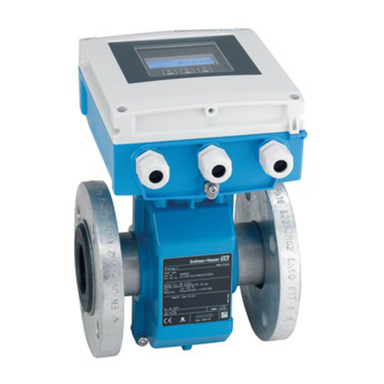
Product description Proline Promag L 400 HART Product description Product design A0017218 å 1 Important components of the compact version Display module Electronics cover HistoROM DAT (plug-in memory) Main electronics module Terminals (screw terminals, some available as plug-in terminals) Transmitter housing, compact version…
-
Page 11: Registered Trademarks
Registered trademark of the HART Communication Foundation, Austin, USA Ò Microsoft Registered trademark of the Microsoft Corporation, Redmond, Washington, USA Ò Ò Ò Applicator , FieldCare , Field Xpert , HistoROM Registered or registration-pending trademarks of the Endress+Hauser Group Endress+Hauser…
-
Page 12: Incoming Acceptance And Product
A0015502 A0013699 Do the nameplate data match the ordering information on the delivery note? A0015502 A0013697 Is the CD-ROM with the Technical Documentation and documents present? If one of the conditions is not satisfied, contact your Endress+Hauser Sales Center. Endress+Hauser…
-
Page 13: Product Identification
Proline Promag L 400 HART Incoming acceptance and product identification Product identification The following options are available for identification of the measuring device: • Nameplate specifications • Order code with breakdown of the device features on the delivery note • Enter serial numbers from nameplates in W@M Device Viewer (www.endress.com/deviceviewer): All information about the measuring device is displayed.
-
Page 14: Sensor Nameplate
Incoming acceptance and product identification Proline Promag L 400 HART 4.2.2 Sensor nameplate Order Code: Ser.No.: Ext. ord. cd.: Material: Patents Date: A0017186 å 4 Example of sensor nameplate Name of the sensor Manufacturing location Order code Serial number (Ser. no.) Extended order code (Ext.
-
Page 15: Symbols On Measuring Device
Proline Promag L 400 HART Incoming acceptance and product identification 4.2.3 Symbols on measuring device Symbol Meaning WARNING! This symbol alerts you to a dangerous situation. Failure to avoid this situation can result in serious or fatal injury. Reference to documentation Refers to the corresponding device documentation.
-
Page 16: Storage And Transport
Storage and transport Proline Promag L 400 HART Storage and transport Storage conditions Observe the following notes for storage: • Store in the original packaging to ensure protection from shock. • Do not remove protective covers or protective caps installed on process connections. They prevent mechanical damage to the sealing surfaces and contamination in the measuring tube.
-
Page 17: Packaging Disposal
Proline Promag L 400 HART Storage and transport A0016257 Packaging disposal All packaging materials are environmentally friendly and 100% recyclable: • Measuring device secondary packaging: polymer stretch film that conforms to EC Directive 2002/95/EC (RoHS). • Packaging: – Wood crate, treated in accordance with ISPM 15 standard, which is confirmed by the affixed IPPC logo.
-
Page 18: Installation
Installation Proline Promag L 400 HART Installation Installation conditions No special measures such as supports are necessary. External forces are absorbed by the construction of the device. 6.1.1 Mounting position Mounting location Preferably install the sensor in an ascending pipe, and ensure a sufficient distance to the next pipe elbow: h = ³…
-
Page 19
Proline Promag L 400 HART Installation Installation in partially filled pipes A partially filled pipe with a gradient necessitates a drain-type configuration. The empty pipe detection (EPD) function offers additional protection by detecting empty or partially filled pipes. • Do not install the sensor at the lowest point in the drain: risk of solids accumulating. -
Page 20
Installation Proline Promag L 400 HART A0015591 Horizontal The measuring electrode plane must be horizontal. This prevents brief insulation of the two measuring electrodes by entrained air bubbles. With horizontal orientation, empty pipe detection only works if the transmitter housing is pointing upwards as otherwise there is no guarantee that the empty pipe detection function will actually respond to a partially filled or empty measuring tube. -
Page 21: Requirements From Environment And Process
Proline Promag L 400 HART Installation 6.1.2 Requirements from environment and process Ambient temperature range Transmitter –20 to +50 °C (–4 to +122 °F) Local display The readability of the display may be impaired at ambient temperatures below –20 °C (–4 °F).
-
Page 22: Special Mounting Instructions
Installation Proline Promag L 400 HART Adapters Suitable adapters to DIN EN 545 (double-flange reducers) can be used to install the sensor in larger- diameter pipes. The resultant increase in the rate of flow improves measuring accuracy with very slow-moving fluids. The nomogram shown here can be used to calculate the pressure loss caused by reducers and expanders.
-
Page 23: Preparing The Measuring Device
Proline Promag L 400 HART Installation For sensor For flanges and other process connections: • Screws, nuts, seals etc. are not included in the scope of supply and must be provided by the customer. • Appropriate mounting tools 6.2.2 Preparing the measuring device 1.
-
Page 24
Installation Proline Promag L 400 HART Screw tightening torques Please note the following: • The screw tightening torques listed below apply only to lubricated threads and to pipes not subjected to tensile stress. • Tighten the screws uniformly and in diagonally opposite sequence. -
Page 25
Proline Promag L 400 HART Installation Nominal Pressure rating Threaded Max. screw tightening torque [Nm] diameter fasteners [mm] [bar] [mm] Hard rubber Polyurethane PTFE 1 800 PN 10 44 ´ M45 – – 2 000 PN 6 48 ´ M39 –… -
Page 26: Mounting The Transmitter Of The Remote Version
Installation Proline Promag L 400 HART Nominal diameter Threaded fasteners Max. screw tightening torque [Nm] ([lbf × ft]) [mm] [in] [in] Hard rubber Polyurethane PTFE 64 ´ 2 2 150 931 (687) – – 68 ´ 2 ¼ 2 300 1 048 (773) –…
-
Page 27
Proline Promag L 400 HART Installation CAUTION Excessive force can damage the housing! Avoid excessive mechanical stress. ► The transmitter of the remote version can be mounted in the following ways: • Wall mounting • Pipe mounting Wall mounting 18 (0.71) 14 (0.55) -
Page 28: Turning The Transmitter Housing
Installation Proline Promag L 400 HART ø 20…70 ø ( 0.79…2.75) PH 2 SW 8 mm (in) A0017135 6.2.5 Turning the transmitter housing To provide easier access to the display module in the compact device version, the transmitter housing can be turned: Tightening torques for plastic housing Housing cover fixing screw Max.1.3 Nm…
-
Page 29
Proline Promag L 400 HART Installation TX 20 A0017343 SW 7 A0017344 A0017345 1. Loosen the 4 fixing screws on the housing cover. 2. Open the housing cover. 3. Remove the display module. 4. Remove the terminals. 5. Loosen the fixing screws of the main electronics module. -
Page 30: Post-Installation Check
Installation Proline Promag L 400 HART Post-installation check Is the device undamaged (visual inspection)? Does the measuring device conform to the measuring point specifications? For example: • Process temperature • Process pressure (refer to the section on «Pressure-temperature ratings» in the «Technical Information»…
-
Page 31: Electrical Connection
Proline Promag L 400 HART Electrical connection Electrical connection Connection conditions 7.1.1 Required tools • Torque wrench • For cable entries: Use corresponding tools • For housing cover: Phillips head screwdriver PH 2 • Wire stripper • When using stranded cables: Crimping tool for wire end ferrule 7.1.2…
-
Page 32
Electrical connection Proline Promag L 400 HART Coil current cable Standard cable 2 ´ 0.75 mm (18 AWG) with common, braided copper shield (Æ ~ 7 mm (0.28″)) and individually shielded cores Conductor resistance £ 37 W/km (0.011 W/ft) Capacitance: core/core, £… -
Page 33: Terminal Assignment
Proline Promag L 400 HART Electrical connection 7.1.3 Terminal assignment Transmitter 0-20 mA/4-20 mA HART connection version with additional outputs and inputs 20 21 22 23 24 25 26 27 A0017112 Supply voltage Order code for Terminal numbers «Power supply»…
-
Page 34: Preparing The Measuring Device
Electrical connection Proline Promag L 400 HART Remote version 6 5 7 8 4 37 36 42 41 n.c. n.c. n.c. 5 7 4 37 42 41 A0017275 å 9 Connecting the remote version Transmitter: main electronics module with terminals…
-
Page 35: Preparing The Connecting Cable For The Remote Version
Proline Promag L 400 HART Electrical connection 7.1.5 Preparing the connecting cable for the remote version When terminating the connecting cable, pay attention to the following points: • In the case of electrode cables, make sure that the ferrules do not touch the core shields on the sensor side.
-
Page 36: Connecting The Measuring Device
Electrical connection Proline Promag L 400 HART Connecting the measuring device WARNING Risk of electric shock! Components carry dangerous voltages! Have electrical connection work carried out by correspondingly trained specialists only. ► Observe applicable federal/national installation codes and regulations. ►…
-
Page 37: Connecting The Remote Version
Proline Promag L 400 HART Electrical connection 7.2.2 Connecting the remote version PH 2 20 21 22 23 6 5 7 8 4 37 36 42 41 24 25 26 27 10 (0.4) mm (in) A0017445 å 10 Transmitter: main electronics module with terminals 1.
-
Page 38: Ensuring Potential Equalization
Electrical connection Proline Promag L 400 HART 4. Connect the cable in accordance with the terminal assignment (® ä 34). 5. Tighten the cable strain relief as per the tightening torque specifications (® ä 36). 6. Firmly tighten the cable glands.
-
Page 39
Proline Promag L 400 HART Electrical connection 1. Connect both sensor flanges to the pipe flange via a ground cable and ground them. 2. If DN £ 300 (12″): Mount the ground cable directly on the conductive flange coating of the sensor with the flange screws.If DN ³… -
Page 40: Ensuring The Degree Of Protection
Electrical connection Proline Promag L 400 HART – A0016319 å 15 Potential equalization and cathodic protection Isolation transformer power supply Electrically isolated from the pipe Capacitor Ground cable Copper wire, at least 6 mm (0.0093 in 1. Connect the measuring device to the power supply such that it is floating in relation to the protective ground.
-
Page 41: Post-Connection Check
Proline Promag L 400 HART Electrical connection Post-connection check Are cables or the device undamaged (visual inspection)? Do the cables comply with the requirements (® ä 31)? Do the cables have adequate strain relief? Are all the cable glands installed, firmly tightened and leak-tight? Cable run with «water trap» (® ä 40) ? Only for remote version: is the sensor connected to the right transmitter? Check the serial number on the nameplate of the sensor and transmitter.
-
Page 42: Operation Options
Operation options Proline Promag L 400 HART Operation options Overview of operation options A0015607 Local operation via display module Computer with Web browser (e.g. Internet Explorer) or with operating tool (e.g. FieldCare, AMS Device Manager, SIMATIC PDM) Field Xpert SFX100 Field Communicator 475 Control system (e.g.
-
Page 43: Structure And Function Of The Operating Menu
Proline Promag L 400 HART Operation options Structure and function of the operating menu 8.2.1 Structure of the operating menu For an overview of the operating menu with menus and parameters (® ä 143) Operating menu for operators and maintenances…
-
Page 44: Operating Philosophy
Operation options Proline Promag L 400 HART 8.2.2 Operating philosophy The individual parts of the operating menu are assigned to certain user roles. Each user role corresponds to typical tasks within the device lifecycle. Menu User role and tasks Content/meaning…
-
Page 45: Access To The Operating Menu Via The Local Display
Proline Promag L 400 HART Operation options Access to the operating menu via the local display 8.3.1 Operational display X X X X X X X 1120.50 A0016502 Operational display Device tag (® ä 86) Status area Display area for measured values (4-line) Operating elements (®…
-
Page 46: Navigation View
Operation options Proline Promag L 400 HART Volume flow A0013711 Conductivity A0017269 Mass flow A0013710 Totalizer The measurement channel number indicates which of the three totalizers is displayed. A0013943 Output The measurement channel number indicates which of the outputs is displayed.
-
Page 47
Proline Promag L 400 HART Operation options Navigation path The navigation path — displayed at the top left in the navigation view — consists of the following elements: • In the submenu: Omission symbol for operating Name of current Display symbol for menu menu levels in between •… -
Page 48: Editing View
Operation options Proline Promag L 400 HART Wizard A0013968 Parameters within a wizard No display symbol exists for parameters in submenus. A0013972 Locking Symbol Meaning Parameter locked When displayed in front of a parameter name, indicates that the parameter is locked.
-
Page 49
Proline Promag L 400 HART Operation options Inserts minus sign at the input position. – A0016620 Confirms selection. A0013985 Moves the input position one position to the left. A0016621 Exits the input without applying the changes. A0013986 Clears all entered characters. -
Page 50: Operating Elements
Operation options Proline Promag L 400 HART 8.3.4 Operating elements Meaning Minus key In a menu, submenu Moves the selection bar upwards in a choose list. With a Wizard Confirms the parameter value and goes to the previous parameter. A0013969 With a text and numeric editor In the input mask, moves the selection bar to the left (backwards).
-
Page 51
Proline Promag L 400 HART Operation options • Setup • Simulation Calling up and closing the context menu The user is in the operational display. 1. Press F for 2 s. Ã The context menu opens. XXXXXXXXXX 20.50 Setup Simulation A0017421-EN 2. -
Page 52: Navigating And Selecting From List
Operation options Proline Promag L 400 HART 8.3.6 Navigating and selecting from list Different operating elements are used to navigate through the operating menu. The navigation path is displayed on the left in the header. Icons are displayed in front of the individual menus. These icons are also shown in the header during navigation.
-
Page 53: Calling Up Help Text
Proline Promag L 400 HART Operation options The direct access code consists of a 4-digit number and the channel number, which identifies the channel of a process variable: e.g. 0914-1. In the navigation view, this appears on the right-hand side in the header of the selected parameter.
-
Page 54: Changing The Parameters
Operation options Proline Promag L 400 HART 8.3.9 Changing the parameters For a description of the editing display — consisting of text editor and numeric editor — with symbols (® ä 48), for a description of the operating elements (® ä 50) Example: Changing the parameter «20 mA value»…
-
Page 55: User Roles And Related Access Authorization
Proline Promag L 400 HART Operation options A message is displayed if the value entered is outside the permitted value range. Ent. access code Invalid or out of range input value Min:0 Max:9999 A0014049-EN 8.3.10 User roles and related access authorization The two user roles «Operator»…
-
Page 56: Access To The Operating Menu Via The Web Browser
Operation options Proline Promag L 400 HART A0016215-EN After disabling the keypad lock: A0016216-EN If the user attempts to access the operating menu while the keylock is enabled, the message Keylock on also appears. Access to the operating menu via the Web browser 8.4.1…
-
Page 57: Establishing A Connection
Proline Promag L 400 HART Operation options 8.4.3 Establishing a connection Configuring the Internet protocol of the computer IP address 192.168.1.XXX; for XXX all numerical values except: 0, 212 and 255 ® e.g. 192.168.1.213 Subnet mask 255.255.255.0 Default gateway 192.168.1.212 or 0.0.0.0 1.
-
Page 58: User Interface
Operation options Proline Promag L 400 HART 8.4.5 User interface A0017757-EN Picture of device Function row with 6 functions Device tag Header Working area Navigation area Header The following information appears in the header: • Device tag (® ä 86) •…
-
Page 59: Disabling The Web Server
Proline Promag L 400 HART Operation options 8.4.6 Disabling the Web server The Web server of the measuring device can be switched on and off as required using the Web server functionality parameter. Navigation path «Expert» menu ® Communication ® Web server ® Web server functionality…
-
Page 60: Access To The Operating Menu Via The Operating Tool
Operation options Proline Promag L 400 HART Access to the operating menu via the operating tool The structure of the operating menu in the operating tools is the same as for operation via the local display. 8.5.1 Connecting the operating tool…
-
Page 61: Field Xpert Sfx100
FieldCare Function scope FDT-based plant asset management tool from Endress+Hauser. It can configure all smart field devices in a system and helps you manage them. By using the status information, it is also a simple but effective way of checking their status and condition.
-
Page 62: Ams Device Manager
Operation options Proline Promag L 400 HART User interface A0017401-EN Header Picture of device Device tag (® ä 86) Status area with status signal (® ä 109) Display area for current measured values (® ä 98) Event list with additional functions such as save/load, events list and document creation…
-
Page 63: Field Communicator 475
Proline Promag L 400 HART Operation options 8.5.6 Field Communicator 475 Function scope Industrial handheld terminal from Emerson Process Management for remote configuration and measured value display via HART protocol. Source for device description files See data (® ä 64)
-
Page 64: System Integration
System integration Proline Promag L 400 HART System integration Overview of device description files 9.1.1 Current version data for the device Firmware version 01.00.zz • On the title page of the Operating instructions • On transmitter nameplate(® ä 13) • Parameter firmware version Diagnostics ®…
-
Page 65: Other Settings
Proline Promag L 400 HART System integration The assignment of the measured variables to the dynamic variables can be modified and assigned as desired via local operation and the operating tool using the following parameters: • Expert ® Communication ® HART output ® Output ® Assign PV •…
-
Page 66: Commissioning
Commissioning Proline Promag L 400 HART Commissioning 10.1 Function check Before commissioning the device, make sure that the post-installation and post-connection checks have been performed. • «Post-mounting check» checklist (® ä 30) • «Post-connection check» checklist (® ä 41) 10.2 Switching on the measuring device After a successful function check, switch on the measuring device.
-
Page 67: Configuring The Measuring Device
Proline Promag L 400 HART Commissioning 10.4 Configuring the measuring device The Setup menu with its guided wizards contains all parameters needed for standard operation. Navigation to the «Setup» menu X X X X X X X 20.50 Main menu…
-
Page 68
Commissioning Proline Promag L 400 HART Sequence of the wizard Assign stat.inp. Reset totaliz. Reset all tot. Flow override 1…3 Active level High Response time End of wizard A0017422-EN å 21 «Status input» wizard in the «Setup» menu Parameter overview with brief description… -
Page 69: Configuring The Current Output
Proline Promag L 400 HART Commissioning 10.4.2 Configuring the current output The Current output wizard guides you systematically through all parameters that have to be set for configuring the specific current output. Navigation path «Setup» menu ® Current output Sequence of the wizard Assign curr.
-
Page 70: Configuring The Pulse/Frequency/Switch
Commissioning Proline Promag L 400 HART Volume flow unit Select volume flow unit. Unit choose list Depends on country and nominal diameter Result The selected unit applies for: – Outputs – Low flow cutoff – Simulation process variable Conductivity unit…
-
Page 71
Proline Promag L 400 HART Commissioning Sequence of the wizard for the pulse output Operating mode Pulse Assign pulse Volume flow Mass flow Volume unit Mass unit Density unit Fixed density Value per pulse Pulse width Failure mode Invert outp.sig. -
Page 72
Commissioning Proline Promag L 400 HART Mass unit Select the unit for mass. Unit choose list Depends on country and nominal diameter Result The selected unit is taken from: Mass flow unit Density unit Select the unit for density. Unit choose list Country-dependent •… -
Page 73
Proline Promag L 400 HART Commissioning Sequence of the wizard for the frequency output Operating mode Frequency Assign freq. Volume flow Conductivity Mass flow Volume unit Conductiv. unit Mass unit Density unit Fixed density Min. freq. value Max. freq. value Val. -
Page 74
Commissioning Proline Promag L 400 HART Assign frequency output Select the process variable for • Off the frequency output. • Volume flow • Conductivity • Mass flow Volume flow unit Select the unit for volume Unit choose list Depends on country and flow. -
Page 75
Proline Promag L 400 HART Commissioning Sequence of the wizard for the switch output Operating mode Switch Switch out funct Diag. behavior Assign diag. beh Alarm or Warning Alarm warning Invert outp.sig. End of wizard A0017439-EN å 25 «Pulse/frequency/switch output 1-2» wizard in the «Setup» menu: «Switch» operating mode (Part 1) -
Page 76
Commissioning Proline Promag L 400 HART Operating mode Switch Switch out funct Fl. direct. Limit Status check Assign Assign Assign limit dir.check status Conduc- Empty Volume Mass Totalizer Volume Mass Low flow tivity pipe det. flow flow 1/2/3 flow flow… -
Page 77
Proline Promag L 400 HART Commissioning Assign limit Select the process variable for • Volume flow Volume flow the limit function. • Conductivity • Mass flow • Totalizer 1 • Totalizer 2 • Totalizer 3 Assign flow direction check Select the process variable for •… -
Page 78: Configuring The Local Display
Commissioning Proline Promag L 400 HART 10.4.4 Configuring the local display The Display wizard guides you systematically through all parameters that can configured for configuring the local display. Navigation path «Setup» menu ® Display Sequence of the wizard Format display…
-
Page 79: Configuring The Output Conditioning
Proline Promag L 400 HART Commissioning Value 1 display Select the measured value • Volume flow Volume flow that is shown on the local • Conductivity display. • Mass flow • Totalizer 1 • Totalizer 2 • Totalizer 3 • Current output 1…
-
Page 80
Commissioning Proline Promag L 400 HART Sequence of the wizard Display damping Damping out. 1 Damping out. 2 Damping out. 3 Assign curr. Volume flow Conductivity Mass flow Assign pulse Volume flow Mass flow Assign freq. Volume flow Conductivity Mass flow… -
Page 81: Configuring The Low Flow Cut Off
Proline Promag L 400 HART Commissioning Assign current output Select process variable for • Off Volume flow current output. • Volume flow • Conductivity • Mass flow Assign pulse output 1-2 Select the process variable for • Off the pulse output.
-
Page 82
Commissioning Proline Promag L 400 HART Switch-on value Enter the on value for low Positive floating-point flow cutoff. number 0 to 100 % 50 % Switch-off value Enter the off value for low flow cutoff. Pressure shock suppression Enter the time interval for… -
Page 83: Configuring Empty Pipe Detection
Proline Promag L 400 HART Commissioning 10.4.7 Configuring empty pipe detection The Empty pipe detection (EPD) wizard guides you systematically through all parameters that have to be set for configuring empty pipe detection. Navigation path «Setup» menu ® Empty pipe detection Sequence of the wizard Empty pipe det.
-
Page 84
Commissioning Proline Promag L 400 HART Response time empty pipe Enter the time interval until the 0 to 100 s detection diagnostic message S862 Partially Filled Pipe is displayed for an empty or partially filled pipe. Endress+Hauser… -
Page 85: Advanced Settings
Proline Promag L 400 HART Commissioning 10.5 Advanced settings The Advanced setup menu with its submenus contains all parameters needed for specific settings. Navigation path «Setup» menu ® Advanced setup Navigation to the «Advanced setup» submenu X X X X X X X 20.50…
-
Page 86: Defining The Tag Name
Commissioning Proline Promag L 400 HART Totalizer 2 ® (® ä 89) ® Totalizer 3 (® ä 89) Display ® (® ä 91) 10.5.1 Defining the tag name To enable quick identification of the measuring point within the system, you can enter a unique designation using the Device tag parameter and thus change the factory setting.
-
Page 87: Carrying Out A Sensor Adjustment
Proline Promag L 400 HART Commissioning Temperature unit Parameter overview with brief description Parameter Description Selection/ Factory setting Volume flow unit Select the unit for volume Unit choose list Country-dependent: flow. • m • gal/min Result The selected unit applies for: –…
-
Page 88: Performing Electrode Cleaning
Commissioning Proline Promag L 400 HART Navigation path «Setup» menu ® Advanced setup ® Sensor adjustment Structure of the submenu Sensor adjustment ® Installation direction Parameter overview with brief description Parameter Description Selection/ Factory setting Installation direction Change the sign of the •…
-
Page 89: Configuring The Totalizer
Proline Promag L 400 HART Commissioning ECC recovery time The following option is Specify the recovery 1 to 600 s selected in the time after electrode Electrode cleaning cleaning to prevent circuit parameter: fluctuations in the signal outputs. The last flow…
-
Page 90
Commissioning Proline Promag L 400 HART Totalizer operation One of the following options is Select totalizer • Net flow total Net flow total mode selected in the Assign process calculation mode. • Forward flow total variable parameter: • Reverse flow total •… -
Page 91: Carrying Out Additional Display Configurations
Proline Promag L 400 HART Commissioning 10.5.6 Carrying out additional display configurations In the Display submenu, you can set all parameters involved in the configuration of the local display. Navigation path «Setup» menu ® Advanced setup ® Display Structure of the submenu Display ®…
-
Page 92: Simulation
Commissioning Proline Promag L 400 HART Decimal places 2 A measured value is specified in Select the number of • x x.xx the parameter Value 2 decimal places for • x.x the display value. • x.xx display. • x.xxx • x.xxxx…
-
Page 93
Proline Promag L 400 HART Commissioning Assign simulation process variable Value process variable Simulation status input Value status input Simulation current output Value current output Frequency simulation 1 Frequency value 1 Pulse simulation 1 Pulse value 1 Switch output simulation 1… -
Page 94: Protecting Settings From Unauthorized Access
Commissioning Proline Promag L 400 HART Value status input The On option is selected in the Select the input • High High Status input simulation signal level of the • Low status input for the parameter. simulation. Simulation current Switch simulation of •…
-
Page 95: Write Protection Via Access Code
Proline Promag L 400 HART Commissioning 10.7.1 Write protection via access code The effects of the customer-specific access code are as follows: • Via local operation, the parameters for the measuring device configuration are write-protected and their values can no longer be changed.
-
Page 96: Write Protection Via Write Protection Switch
Commissioning Proline Promag L 400 HART Reset all totalizers Defining the access code via the Web browser 1. Navigate to the Define access code parameter. 2. Define a max. 4-digit numeric code as an access code. 3. Enter the access code again to confirm the code.
-
Page 97
Proline Promag L 400 HART Commissioning X X X X X X X 4.00 A0015870 If hardware write protection is disabled, no option is displayed in the Locking status parameter (® ä 98). On the local display, the -symbol disappears from in front of the parameters in the header of the operational display and in the navigation view. -
Page 98: Operation
Operation Proline Promag L 400 HART Operation 11.1 Read device locking status The write protection types that are currently active can be determined using the Locking status parameter. Navigation path «Expert» menu ® Locking status Function scope of «Locking status» parameter…
-
Page 99: Totalizer
Proline Promag L 400 HART Operation Parameter overview with brief description Parameter Description Display Volume flow Displays the calculated volume flow Floating-point number with sign Conductivity Displays the conductivity currently Floating-point number calculated Mass flow Displays the mass flow currently…
-
Page 100: Output Values
Operation Proline Promag L 400 HART The submenu only appears if the device was ordered with a status input (® ä 33). Structure of the submenu Input values ® Value status input Parameter overview with brief description Parameter Prerequisite Description…
-
Page 101: Adapting The Measuring Device To The Process Conditions
Proline Promag L 400 HART Operation Measured current Displays the current value • 0-20 mA: currently measured for 0 to 22.5 mA the current output. • 4-20 mA: 3.59 to 22.5 mA Pulse output 1-2 Displays the value Positive floating-point…
-
Page 102: Showing Data Logging
Operation Proline Promag L 400 HART Preset value 2 Control totalizer 3 Preset value 3 Reset all totalizers Parameter overview with brief description Parameters Prerequisite Description Selection/ Factory setting User entry Control totalizer 1-3 Control totalizer • Totalize Totalize value.
-
Page 103
Proline Promag L 400 HART Operation Assign channel 1 Assign channel 2 Assign channel 3 Assign channel 4 Logging interval Clear logging data Display channel 1 Display channel 2 Display channel 3 Display channel 4 Parameter overview with brief description… -
Page 104: Diagnostics And Troubleshooting
Diagnostics and troubleshooting Proline Promag L 400 HART Diagnostics and troubleshooting 12.1 General troubleshooting For local display Problem Possible cause Remedy Local display dark and no output signals Supply voltage does not match that Apply the correct supply voltage specified on the nameplate.
-
Page 105
Proline Promag L 400 HART Diagnostics and troubleshooting No write access to parameters Current user role has limited access 1. Check user role (® ä 55). authorization 2. Enter correct customer-specific access code (® ä 55). No connection via HART protocol… -
Page 106: Diagnostic Information On Local Display
Diagnostics and troubleshooting Proline Promag L 400 HART 12.2 Diagnostic information on local display 12.2.1 Diagnostic message Faults detected by the self-monitoring system of the measuring device are displayed as a diagnostic message in alternation with the operational display. Operational display in alarm condition…
-
Page 107
Proline Promag L 400 HART Diagnostics and troubleshooting Diagnostic behavior Symbol Meaning Alarm • Measurement is interrupted. • Signal outputs and totalizers assume the defined alarm condition. • A diagnostic message is generated. A0013961 • The background lighting changes to red. -
Page 108: Calling Up Remedy Information
Diagnostics and troubleshooting Proline Promag L 400 HART 12.2.2 Calling up remedy information X X X X X X X X X X X X X X 20.50 S441 Curr. output 1 Curr. output 1 (ID:153) S441 2d11h05m55s 1. Check process 2.
-
Page 109: Diagnostic Information In The Web Browser
Proline Promag L 400 HART Diagnostics and troubleshooting 12.3 Diagnostic information in the Web browser 12.3.1 Diagnostic options Any faults detected by the measuring device are displayed in the Web browser on the home page once the user has logged on.
-
Page 110: Diagnostic Information In Fieldcare
Diagnostics and troubleshooting Proline Promag L 400 HART 12.4 Diagnostic information in FieldCare 12.4.1 Diagnostic options Any faults detected by the measuring device are displayed on the home page of the operating tool once the connection has been established. A0017399-EN Status area with status signal (®…
-
Page 111: Overview Of Diagnostic Information
Proline Promag L 400 HART Diagnostics and troubleshooting A0014048-EN å 35 Illustrated using the example of the local display You can assign the following options to the diagnostic number as the diagnostic behavior: Options Description Alarm Measurement is interrupted. Signal outputs and totalizers assume the defined alarm condition. A diagnostic message is generated.
-
Page 112
Diagnostics and troubleshooting Proline Promag L 400 HART Electronic failure 1. Reset device. Alarm 2. Contact service. Electronic failure Maintenance required! Warning 1. Do not perform reset. 2. Contact service. Data storage 1. Insert DAT module. Alarm 2. Replace DAT module. -
Page 113: Pending Diagnostic Events
Proline Promag L 400 HART Diagnostics and troubleshooting Switch output simulation Switch off switch output simulation. Warning Simulation status input Switch off status input simulation. Warning Empty pipe detection Perform empty pipe detection Warning adjustment. Diagnostic behavior can be changed: «Adapting the diagnostic behavior» section (® ä 110)
-
Page 114: Diagnostic List
Diagnostics and troubleshooting Proline Promag L 400 HART Previous diagnostics 2 diagnostic events have Displays the diagnostic event Symbol for diagnostic already occurred that occurred prior to the behavior, diagnostic code current diagnostic event and short message along with the diagnostic information.
-
Page 115: Filtering The Event Logbook
Proline Promag L 400 HART Diagnostics and troubleshooting The event history includes entries for: • Diagnostic events (® ä 111) • Information events (® ä 115) In addition to the operation time of its occurrence, each event is also assigned a symbol that indicates whether the event has occurred or is ended: •…
-
Page 116: 12.10 Resetting The Measuring Device
Diagnostics and troubleshooting Proline Promag L 400 HART I1335 Firmware changed I1351 Empty pipe detection adjustment failure I1353 Empty pipe detection adjustment Ok I1355 ECC switched on I1361 Incorrect Web server login 12.10 Resetting the measuring device Using the Device reset parameter it is possible to reset the entire device configuration or some of the configuration to a defined state.
-
Page 117
Proline Promag L 400 HART Diagnostics and troubleshooting ENP version Device revision Device ID Device type Manufacturer ID IP address Subnet mask Default gateway Parameter overview with brief description Parameter Prerequisite Description Display Serial number Displays the serial number of Max. -
Page 118: 12.12 Disposal
Diagnostics and troubleshooting Proline Promag L 400 HART Device ID Displays the device ID for 6-digit hexadecimal number identifying the device in a HART network. Device type Displays the device type with 0x47 which the measuring device is registered with the HART Communication Foundation.
-
Page 119: Repair
• Spare parts are grouped into logical kits with the associated Installation Instructions. • Repairs are carried out by Endress+Hauser Service or by correspondingly trained customers. • Certified devices can be converted into other certified devices by Endress+Hauser Service or at the factory only.
-
Page 120: Maintenance
No interior cleaning is planned for the device. 14.2 Measuring and test equipment Endress+Hauser offers a wide variety of measuring and test equipment, such as W@M or device tests. Your Endress+Hauser Sales Center can provide detailed information on the services.
-
Page 121: Return
The measuring device must be returned if repairs or a factory calibration are required, or if the wrong measuring device has been ordered or delivered. According to legal regulations, Endress+Hauser, as an ISO-certified company, is required to follow certain procedures when handling returned products that are in contact with medium.
-
Page 122: Technical Data
Technical data Proline Promag L 400 HART Technical data 16.1 Application The measuring device is only suitable for flow measurement of liquids with a minimum conductivity of 5 mS/cm. In the case of demineralized water, a minimum conductivity of 20 mS/cm is required.
-
Page 123
Proline Promag L 400 HART Technical data Nominal Recommended Factory settings diameter flow Full scale value current min./max. full scale value Pulse value Low flow cut off output (v ~ 0.3/10 m/s (v ~ 0.04 m/s) (~ 2 pulse/s) (v ~ 2.5 m/s) -
Page 124
Technical data Proline Promag L 400 HART Nominal Recommended Factory settings diameter flow Full scale value current min./max. full scale value Pulse value Low flow cut off output (v ~ 0.3/10 m/s (v ~ 0.04 m/s) (~ 2 pulse/s) (v ~ 2.5 m/s) -
Page 125: Output
Proline Promag L 400 HART Technical data Status input Input signal Maximum input values • DC 30 V • 6 mA Response time Adjustable: 5 to 200 ms Input signal level • Low signal: DC –3 to +5 V • High signal: DC 12 to 30 V Assignable functions •…
-
Page 126
Technical data Proline Promag L 400 HART Assignable measured • Volume flow variables • Conductivity • Mass flow Switch output Switching behavior Binary, conductive or non-conductive Switching delay Adjustable: 0 to 100 s Number of switching cycles Unlimited Assignable functions •… -
Page 127: Power Supply
Proline Promag L 400 HART Technical data Switch output Failure mode Choose from: • Current status • Open • Closed Local display Plain text display With information on cause and remedial measures Backlight Red backlighting indicates a device error. Status signal as per NAMUR recommendation NE 107 Operating tool •…
-
Page 128
Technical data Proline Promag L 400 HART Power consumption Transmitter Order code for Maximum power consumption «Power supply» Option A: AC 100 to 230 V 30 VA Option B: AC/DC 24 V 30 VA/8 W Current consumption Transmitter Order code for… -
Page 129: Performance Characteristics
Proline Promag L 400 HART Technical data 16.6 Performance characteristics Reference operating To DIN EN 29104 conditions • Fluid temperature: +28 ± 2 °C (+82 ± 4 °F) • Ambient temperature range: +22 ± 2 °C (+72 ± 4 °F) •…
-
Page 130: Installation
Technical data Proline Promag L 400 HART Influence of ambient o.r. = of reading; o.f.s. = of full scale value temperature Current output Temperature coefficient Typically ±50 ppm/°C o.r. or ±1 µA/°C Pulse/frequency output Temperature coefficient Max.±50 ppm/°C 16.7 Installation «Mounting requirements»…
-
Page 131: Process
Proline Promag L 400 HART Technical data Details are provided in the Declaration of Conformity. 16.9 Process • 0 to +80 °C (+32 to +176 °F) for hard rubber, DN 350 to 2400 (14 to 90″) Medium temperature range • –20 to +50 °C (–4 to +122 °F) for polyurethane, DN 50 to 1200 (2 to 48″) •…
-
Page 132: 16.10 Mechanical Construction
Technical data Proline Promag L 400 HART Pressure loss • No pressure loss occurs if the sensor is installed in a pipe with the same nominal diameter. • Pressure losses for configurations incorporating adapters according to DIN EN 545 (® ä 22) System pressure (®…
-
Page 133
Proline Promag L 400 HART Technical data Nominal EN (DIN) ASME, AWWA diameter [mm] [in] Pressure [kg] Pressure [kg] Pressure [kg] Pressure [kg] Pressure [kg] rating rating rating rating rating 1 200 PN 10 PN 6 Class D PN 16… -
Page 134
Technical data Proline Promag L 400 HART Nominal diameter ASME, AWWA [mm] [in] Pressure rating [lbs] Class 150 Class 150 – Class 150 Class 150 Class 150 Class 150 Class D Class D Class D Class D 1 041 1 000… -
Page 135
Proline Promag L 400 HART Technical data Nominal EN (DIN) ASME, AWWA diameter [mm] [in] Pressure [kg] Pressure [kg] Pressure [kg] Pressure [kg] Pressure [kg] rating rating rating rating rating PN 10 PN 6 – Class 150 PN 16 –… -
Page 136
Technical data Proline Promag L 400 HART Weight in US units Lap joint flange; fixed flange DN ³ 350 (14″) Nominal diameter ASME, AWWA [mm] [in] Pressure rating [lbs] Class 150 2 ½ Class 150 – Class 150 Class 150 Class 150 –… -
Page 137
Proline Promag L 400 HART Technical data Nominal diameter Pressure rating Measuring tube internal diameter EN (DIN) ASME AS 2129 Hard rubber Polyurethane PTFE AWWA AS 4087 [mm] [in] [mm] [in] [mm] [in] [mm] [in] PN 10/16 Class 150 –… -
Page 138
Technical data Proline Promag L 400 HART Nominal diameter Pressure rating Measuring tube internal diameter EN (DIN) ASME AS 2129 Hard rubber Polyurethane PTFE AWWA AS 4087 [mm] [in] [mm] [in] [mm] [in] [mm] [in] PN 10 – – 35.2 35.4… -
Page 139
Proline Promag L 400 HART Technical data Transmitter cable entries Order code for «Housing», option M «Compact, polycarbonate»; option N «Remote, polycarbonate» The various cable entries are suitable for hazardous and non-hazardous areas. Electrical connection Material Cable gland M20 × 1.5 Plastic Thread G ½»… -
Page 140
Technical data Proline Promag L 400 HART Process connections EN 1092-1 (DIN 2501) • DN £ 300 (12″): 1.0038 (S235JRG2), 1.4301/304, 1.4306/304L, 1.4307/304L • DN ³ 350 (14″): 1.0038 (S235JRG2), A105 ASME B16.5 • DN £ 300 (12″): A105, 316L •… -
Page 141: 16.11 Operability
The measuring system is in conformity with the statutory requirements of the applicable EC Directives. These are listed in the corresponding EC Declaration of Conformity along with the standards applied. Endress+Hauser confirms successful testing of the device by affixing to it the CE mark. Endress+Hauser…
-
Page 142: 16.13 Application Packages
Technical data Proline Promag L 400 HART C-Tick symbol The measuring system meets the EMC requirements of the «Australian Communications and Media Authority (ACMA)». Ex approval The devices are certified for use in hazardous areas and the relevant safety instructions are provided in the separate «Control Drawing»…
-
Page 143: Appendix
Proline Promag L 400 HART Appendix Appendix 17.1 Overview of the operating menu The following table provides an overview of the entire operating menu structure with menus and parameters. The direct access code to the parameter is given in brackets. The page reference indicates where a description of the parameter can be found in the manual.
-
Page 144
Appendix Proline Promag L 400 HART Mass flow unit (® ä 70) Density unit (® ä 70) Fixed density (® ä 70) Current span (® ä 70) 0/4 mA value (® ä 70) 20 mA value (® ä 70) Failure mode (®… -
Page 145
Proline Promag L 400 HART Appendix Measuring value at (® ä 74) maximum frequency Failure mode (® ä 74) Failure frequency (® ä 74) Invert output signal (® ä 74) Switching output ® (® ä 75) Operating mode (® ä 76) Switch output function (®… -
Page 146
Appendix Proline Promag L 400 HART ® Output conduct (® ä 79) Display damping (® ä 80) Output damping 1 to 3 (® ä 80) Assign current output (® ä 69) Assign pulse output (® ä 71) Assign frequency output (®… -
Page 147
Proline Promag L 400 HART Appendix Mass unit (® ä 87) Density unit (® ä 87) Temperature unit (® ä 87) Sensor adjustment ® (® ä 87) Installation direction (® ä 88) Electrode cleaning ® (® ä 88) circuit* Electrode cleaning circuit* (®… -
Page 148
Appendix Proline Promag L 400 HART Display damping (® ä 92) Header (® ä 92) Header text (® ä 92) Separator (® ä 92) Backlight (® ä 92) ® Diagnostics (® ä 104) Actual diagnostics (® ä 114) Timestamp Previous diagnostics (®… -
Page 149
Proline Promag L 400 HART Appendix Subnet mask (® ä 118) Default gateway (® ä 118) Measured values ® (® ä 98) Process variables ® (® ä 98) Volume flow (® ä 99) Conductivity (® ä 99) Mass flow (® ä 99) Totalizer ®… -
Page 150
Appendix Proline Promag L 400 HART Frequency (® ä 94) simulation 1 to 2 Frequency value 1 to 2 (® ä 94) Pulse simulation 1 to 2 (® ä 94) Pulse value 1 to 2 (® ä 94) Switch output (®… -
Page 151
Proline Promag L 400 HART Appendix 100% bargraph value 3 (® ä 79) (0126) Decimal places 3 (0118) (® ä 92) Value 4 display (0109) (® ä 79) Decimal places 4 (0119) (® ä 92) Display interval (0096) (® ä 92) Display damping (0094) (®… -
Page 152
Appendix Proline Promag L 400 HART Activate sensor emergency (® ä 111) mode (6611) ® Sensor Measured values ® (® ä 98) ® Process variables (® ä 98) Volume flow (1838) (® ä 99) Conductivity (1850) (® ä 99) Mass flow (1847) (®… -
Page 153
Proline Promag L 400 HART Appendix Conductivity damping (® ä 67) (1803) ® Low flow cut off (® ä 81) Assign process variable (® ä 81) (1837) On value low flow cutoff (® ä 82) (1805) Off value low flow cutoff (®… -
Page 154
Appendix Proline Promag L 400 HART Volume flow factor (1832) (® ä 87) Volume flow offset (1831) (® ä 87) Conductivity factor (1849) (® ä 87) Conductivity offset (1848) (® ä 87) Mass flow factor (1846) (® ä 87) Mass flow offset (1841) (®… -
Page 155
Proline Promag L 400 HART Appendix Measured current 1 (0366) (® ä 101) PFS output 1 to 2 ® (® ä 70) ® Pulse output (® ä 71) Operating mode (0469) (® ä 71) Assign pulse output (0460) (® ä 71) Value per pulse (0455) (®… -
Page 156
Appendix Proline Promag L 400 HART Assign diagnostic behavior (® ä 76) (0482) Assign limit (0483) (® ä 77) Switch-on value (0466) (® ä 77) Switch-off value (0464) (® ä 77) Assign flow direction check (® ä 77) (0484) Assign status (0485) (®… -
Page 157
Proline Promag L 400 HART Appendix Assign PV (0234) (® ä 64) Primary variable (PV) (® ä 64) (0201) Assign SV (0235) (® ä 64) Secondary variable (SV) (® ä 64) (0226) Assign TV (0236) (® ä 64) Tertiary variable (TV) (®… -
Page 158
Appendix Proline Promag L 400 HART Timestamp Operating time from restart – (0653) Operating time (0652) (® ä 115) Diagnostics list ® (® ä 114) Diagnostics 1 to 5 (® ä 114) (692 to 696) Timestamp ® Event logbook (® ä 114) Filter options (0705) (®… -
Page 159
Proline Promag L 400 HART Appendix Maximum value (6545) Medium temperature ® Minimum value (6573) Maximum value (6572) Simulation ® (® ä 92) Assign simulation process (® ä 93) variable (1810) Value process variable (® ä 93) (1811) Simulation status input (®… -
Page 160: Index
Index Proline Promag L 400 HART Index Degree of protection ….. . . 40, 130 Design Access authorization to parameters Measuring device .
-
Page 161
Proline Promag L 400 HART Index SIMATIC PDM ……62 Electrical connection Commubox FXA195 ….. . . 60 Galvanic isolation . -
Page 162
Index Proline Promag L 400 HART Maintenance tasks ……120 Menus, submenus ……43 Manufacturer ID . -
Page 163
Proline Promag L 400 HART Index Status area For operational display ….. . . 45 Read access ……. . . 55 In the navigation view . -
Page 164
Index Proline Promag L 400 HART Tool tip see Help text Transmitter Connecting the signal cables ….36 Turning the housing ……28 Transporting the measuring device . -
Page 165
Erklärung zur Kontamination und Reinigung Please reference the Return Authorization Number (RA#), obtained from Endress+Hauser, on all paperwork and mark the RA# clearly on the outside of the box. If this procedure is not followed, it may result in the refusal of the package at our facility. -
Page 166
www.endress.com/worldwide BA01062D/06/EN/01.12 71183770 EH-COSIMA ProMoDo…
(Ocr-Read Summary of Contents of some pages of the Endress+Hauser Proline Promag L 400 Document (Main Content), UPD: 04 September 2023)
-
97, Endress+Hauser Proline Promag L 400 Proline Promag L 400 HART Commissioning Endress+Hauser 97 Parameter overview with brief description Parameters Description Selection / User entry / User interface Factory setting Electrode cleaning circuit Enable the cyclic electrode cleaning circuit. • Off • On Off ECC duration Enter the duration of electrode cleaning in seconds. 0.01 to 30 s 2 s ECC recovery time Define recovery time after electrode cleaning. During this…
-
86, Commissioning Proline Promag L 400 HART 86 Endress+Hauser Parameters Description User entry / Selection Factory setting Assign current output Select process variable for current output. • Off • Volume flow • Mass flow • Flow velocity • Conductivity • Electronic temperature Volume flow Assign pulse output Select process variable for pulse output. • Off • Volume flow • Mass flow Off Assign frequency output Select process variable for frequency output. • Off • Volu…
-
57, Endress+Hauser Proline Promag L 400 Proline Promag L 400 HART Operation options Endress+Hauser 57 Navigation path «Expert» menu → Direct access The direct access code consists of a 4-digit number and the channel number, which identifies the channel of a process variable: e.g. 0914-1. In the navigation view, this appears on the right-hand side in the header of the selected parameter. 1 0914-2 A0017223 1 Direct access code Note the following when …
-
146, Endress+Hauser Proline Promag L 400 Technical data Proline Promag L 400 HART 146 Endress+Hauser Sensor remote version Weight data: • Including sensor connection housing • Excluding the connecting cable • Excluding packaging material Weight in SI units Lap joint flange; fixed flange DN ≥ 350 (14″) Nominal diameter EN (DIN) ASME, AWWA AS [mm] [in] Pressure rating [kg] Pressure rating [kg] Pressure rating [kg] Pressure rating [kg] Pressure rating [kg] Pressure rating [kg] 50 2 PN …
-
105, Proline Promag L 400 HART Operation Endress+Hauser 105 11.5 Adapting the measuring device to the process conditions The following are available for this purpose: • Basic settings using the Setup menu(→ 70) • Advanced settings using the Advanced setup submenu(→ 90) 11.6 Performing a totalizer reset In the Operation submenu the totalizers are reset: • Control Totalizer • Reset all totalizers • Reset all totalizers Navigation «Operation…
-
177, Proline Promag L 400 HART Appendix Endress+Hauser 177 Sensor (12152) Sensor electronics module (12151) I/O module (12145) Monitoring result → Noise (12158) Coil current shot time (12150) Reference electrode potential against PE (12155) Simulation → (→ 97) Assign simulation process variable (1810) Value process variable (1811) Simulation status input (1355) Value status input (1356) Simulation current out…
-
32, Installation Proline Promag L 400 HART 32 Endress+Hauser TX 20 4 x 1. 2. PUSH TO REMOVE PUSH TO REMOVE 3. 4. A0021617 1. Loosen the fixing screws of the housing cover. 2. Open the housing cover. 3. Unlock the display module. 4. Pull out the display module and turn it to the desired position in increments of 90°. 5. WARNING! Excessive tightening torque applied to the fixing screws! Risk of damaging the plastic transmitter. Tighten the fixing screws as per the tightening torque (→ �…
-
31, Proline Promag L 400 HART Installation Endress+Hauser 31 10. 11. 9. 4 mm 4 x A0021605 1. Loosen the fixing screws of the housing cover. 2. Open the housing cover. 3. Unlock the display module. 4. Remove the display module. 5. Loosen the fixing screws of the smart sensor electronics module. 6. Remove the smart sensor electronics module. 7. Loosen the fixing screws of the main electronics module. 8. Remove the main electronics module. 9. Loosen the fixing screws of the transmitter housi…
-
150, Technical data Proline Promag L 400 HART 150 Endress+Hauser Nominal diameter Pressure rating Measuring tube internal diameter EN (DIN) ASME AS 2129 Hard rubber Polyurethane PTFE AWWA AS 4087 [mm] [in] [mm] [in] [mm] [in] [mm] [in] – 84 – Class D – 2 099 84.0 – – – – 2 200 – PN 6 – – 2 194 87.8 – – – – 2 200 – PN 10 – – 2 186 87.4 – – – – – 90 – Class D – 2 246 89.8 – – – – 2 400 – PN 6 – – 2 394 95.8 – – – – 2 400…
-
79, Proline Promag L 400 HART Commissioning Endress+Hauser 79 Structure of the wizard for the switch output End of wizard Operating mode Switch Switch out funct Diag. behavior Off On Assign diag. beh Alarm Alarm or warning Warning Invert outp.sig. A0017439-EN 28 «Pulse/frequency/switch output 1-2» wizard in the «Setup» menu: «Switch» operating mode (Part 1)
… -
67, Proline Promag L 400 HART Operation options Endress+Hauser 67 8.5.6 Field Communicator 475 Function scope Industrial handheld terminal from Emerson Process Management for remote configuration and measured value display via HART protocol. Source for device description files See data (→ 68)
… -
145, Proline Promag L 400 HART Technical data Endress+Hauser 145 Weight in US units Lap joint flange; fixed flange DN ≥ 350 (14″) Nominal diameter ASME, AWWA [mm] [in] Pressure rating [lbs] 1) 50 2 Class 150 20 65 2 ½ Class 150 – 80 3 Class 150 26 100 4 Class 150 31 125 5 Class 150 – 150 6 Class 150 53 200 8 Class 150 95 250 10 Class 150 139 300 12 Class 150 150 350 14 Class 150 302 375 15 Class 150 – 400 16 Class 150 370 450 18 Class 150 421 500 20 Cl…
-
166, Appendix Proline Promag L 400 HART 166 Endress+Hauser Display language (0104) (→ 70) Format display (0098) Value 1 display (0107) 0% bargraph value 1 (0123) 100% bargraph value 1 (0125) Decimal places 1 (0095) Value 2 display (0108) Decimal places 2 (0117) Value 3 display (0110) 0% bargraph value 3 (0124) 100% bargraph value 3 (0126) Decimal places 3 (0118) Value 4 display (0109) Decimal places 4 (0119) Display interval (0096) Display damping (0094) Head…
-
149, Proline Promag L 400 HART Technical data Endress+Hauser 149 Nominal diameter Pressure rating Measuring tube internal diameter EN (DIN) ASME AS 2129 Hard rubber Polyurethane PTFE AWWA AS 4087 [mm] [in] [mm] [in] [mm] [in] [mm] [in] 700 28 PN 10 – – 694 27.3 697 27.4 – – 700 28 – – Table E, PN 16 690 27.2 693 27.3 – – 700 28 – Class D – 694 27.3 697 27.4 – – 750 30 PN 6 – – – – 699 27.5 �…
-
6, Document information Proline Promag L 400 HART 6 Endress+Hauser 1 Document information 1.1 Document function These Operating Instructions contain all the information that is required in various phases of the life cycle of the device: from product identification, incoming acceptance and storage, to mounting, connection, operation and commissioning through to troubleshooting, maintenance and disposal. 1.2 Symbols used 1.2.1 Saf…
-
40, Electrical connection Proline Promag L 400 HART 40 Endress+Hauser 1. 2. 4. 3. 6 5 7 8 4 37 36 42 41 S1 E1 E2 S2 GND E S TX 20 4 x A0017445 12 Transmitter: main electronics module with terminals 1. Loosen the 4 fixing screws on the housing cover. 2. Open the housing cover. 3. Push the cable through the cable entry . To ensure tight sealing, do not remove the sealing ring from the cable entry. 4. Strip the cable and cable ends. In…
-
22, Installation Proline Promag L 400 HART 22 Endress+Hauser 6.1.2 Requirements from environment and process Ambient temperature range Transmitter –40 to +60 °C (–40 to +140 °F) Local display –20 to +60 °C (–4 to +140 °F), the readability of the display may be impaired at temperatures outside the temperature range. Sensor • Flange material carbon steel: –10 to +60 °C (+14 to +140 °F) • Flange material stainless steel: –40 to +60 °C (–40 to +140 °F) Mount the transmitter s…
Table of Contents for Endress+Hauser Proline Promag L 400:
-
Proline Promag L 400 HART Commissioning Endress+Hauser 79 Structure of the wizard for the switch output End of wizard Operating mode Switch Switch out funct Diag. behavior Off On Assign diag. beh Alarm Alarm or warning Warning Invert outp.sig. A0017439-EN 28 «Pulse/frequency/switch output 1-2» wizard in the «Setup» menu: «Switch» operating mode (Part 1)
-
Proline Promag L 400 HART Operation Endress+Hauser 105 11.5 Adapting the measuring device to the process conditions The following are available for this purpose: • Basic settings using the Setup menu(→ 70) • Advanced settings using the Advanced setup submenu(→ 90) 11.6 Performing a totalizer reset In the Operation submenu the totalizers are reset: • Control Totalizer • Reset all totalizers • Reset all totalizers Navigation «Operation» menu → Op
-
Proline Promag L 400 HART Commissioning Endress+Hauser 89 Structure of the wizard Empty pipe det. Response time End of wizard New adjustment Cancel Empty pipe adj. Progress Full pipe adjust. Ok Busy Not ok On Switch point EPD Off A0017210-EN 35 «Empty pipe detection» wizard in the «Setup» menu
-
Commissioning Proline Promag L 400 HART 82 Endress+Hauser Structure of the wizard Formatdisplay Value1display 0%bargraph value1 100%bargraph value1 Value2display Value3display 0%bargraph value3 100%bargraph value3 Value4display Endofwizard A0013797-EN 30 «Display» wizard in the «Setup» menu Parameter overview with brief description Para
-
Proline Promag L 400 HART Technical data Endress+Hauser 137 Pulse/pause ratio 1:1 Assignable measured variables • Volume flow • Mass flow • Flow velocity • Conductivity • Electronics temperature Switch output Switching behavior Binary, conductive or non-conductive Switching delay Adjustable: 0 to 100 s Number of switching cycles Unlimited Assignable functions • Off • On • Diagnostic behavior • Limit value: – Off – Volume flow – Mass flow – Flow velocity – Conductivity – Totalizer
-
Commissioning Proline Promag L 400 HART 92 Endress+Hauser Parameters Description Selection Factory setting Density unit Select density unit. Result The selected unit applies for: • Output • Simulation process variable • Density adjustment (in Expert menu) Unit choose list Country-specific: • kg/l • lb/ft³ Corrected volume flow unit Select corrected volume flow unit. Result The selected unit applies for: • Output • Low flow cut off • Simulation proce
-
Proline Promag L 400 HART Commissioning Endress+Hauser 87 Parameter overview with brief description Parameters Description Selection / User entry Factory setting Assign process variable Select process variable for low flow cut off. • Off • Volume flow • Mass flow Volume flow On value low flow cutoff Enter on value for low flow cut off. Signed floating-point number 0 l/h Off value
-
Commissioning Proline Promag L 400 HART 80 Endress+Hauser Limit Fl. direct. check Status Assign limit Assign dir.check Assign status End of wizard Operating mode Switch Switch out funct Unit Conduc- tivity Totalizer 1/2/3 Mass flow Volume flow Low flow cut off Empty pipe det. Mass flow Volume flow Switch-on value Switch-off value Switch-on delay Switch-off delay Failure mode Invert outp.sig. Volume flow unit Mass flow unit Conductiv. unit A0017440-EN 29 «Pulse/frequency/switch output 1-2» wizard in the «Setup» menu: «Switch»
-
Proline Promag L 400 HART Operation Endress+Hauser 107 Parameter overview with brief description Parameters Description Selection / User entry Factory setting Assign channel 1 Assign process variable to logging channel. • Off • Volume flow • Mass flow • Conductivity • Electronic temperature • Current output 1 Off Assign channel 2 Assign process variable to logging channel. Picklist (see Assign chan. 1 parameter) Off Assign channel 3 Assign process variable to logging channel. Picklist (see Assign chan. 1 parameter) Off Assig
-
Accessories Proline Promag L 400 HART 132 Endress+Hauser Fieldgate FXA520 Gateway for the remote diagnostics and remote configuration of connected HART measuring devices via a Web browser. For details, see «Technical Information» TI00025S and Operating Instructions BA00051S Field Xpert SFX100 Compact, flexible and robust industry handheld terminal for remote configuration and for obtaining measured values via the HART curren
-
Diagnostics and troubleshooting Proline Promag L 400 HART 116 Endress+Hauser 12.5.2 Calling up remedy information Remedy information is provided for every diagnostic event to ensure that problems can be rectified quickly: • On the home page Remedy information is displayed in a separate field below the diagnostics information. • In the Diagnostics menu Remedy information can be called up in the working area of the
-
Technical data Proline Promag L 400 HART 146 Endress+Hauser Sensor remote version Weight data: • Including sensor connection housing • Excluding the connecting cable • Excluding packaging material Weight in SI units Lap joint flange; fixed flange DN ≥ 350 (14″) Nominal diameter EN (DIN) ASME, AWWA AS [mm] [in] Pressure rating [kg] Pressure rating [kg] Pressure rating [kg] Pressure rating [kg] Pressure rating [kg] Pressure rating [kg] 50 2 PN 6 – PN 10 – PN 16 6 Class 150 6 PN 16 – Table E
-
Product description Proline Promag L 400 HART 12 Endress+Hauser 3 Product description 3.1 Product design 1 2 3 5 6 8 7 4 A0017218 1 Important components of the compact version 1 Display module 2 Smart sensor electronics module 3 HistoROM DAT (plug-in memory) 4 Main electronics module 5 Terminals (screw terminals, some available as plug-in terminals) 6 Transmitter housing, compact version 7 Cable glands 8 Sensor, compact version
Questions, Opinions and Exploitation Impressions:
You can ask a question, express your opinion or share our experience of Endress+Hauser Proline Promag L 400 device using right now.
-
Contents
-
Table of Contents
-
Troubleshooting
-
Bookmarks
Quick Links
BA01062D/06/EN/02.13
71218251
Valid as of version
01.00.zz (Device firmware)
Products
Operating Instructions
Proline Promag L 400
HART
Electromagnetic flowmeter
Solutions
Services
Related Manuals for Endress+Hauser Proline Promag L 400
Summary of Contents for Endress+Hauser Proline Promag L 400
-
Page 1: Operating Instructions
Products Solutions Services BA01062D/06/EN/02.13 71218251 Valid as of version 01.00.zz (Device firmware) Operating Instructions Proline Promag L 400 HART Electromagnetic flowmeter…
-
Page 2
• The manufacturer reserves the right to modify technical data without prior notice. Your Endress+Hauser Sales Center will supply you with current information and updates to these Instructions. Endress+Hauser… -
Page 3: Table Of Contents
Proline Promag L 400 HART Table of contents Table of contents 6.2.2 Preparing the measuring device ..24 Document information ….6 6.2.3 Mounting the sensor .
-
Page 4
….. . . 100 13.3 Endress+Hauser services ….128 Operation . -
Page 5
Proline Promag L 400 HART Table of contents 14.5 Disposal ……14.5.1 Removing the measuring device ..129 14.5.2 Disposing of the measuring device . -
Page 6: Document Information
Document information Proline Promag L 400 HART Document information Document function These Operating Instructions contain all the information that is required in various phases of the life cycle of the device: from product identification, incoming acceptance and storage, to mounting, connection, operation and commissioning through to troubleshooting, maintenance and disposal.
-
Page 7: Tool Symbols
Proline Promag L 400 HART Document information 1.2.3 Tool symbols Symbol Meaning Torx screwdriver A0013442 Phillips head screwdriver A0011219 Open-ended wrench A0011222 1.2.4 Symbols for certain types of information Symbol Meaning Allowed Indicates procedures, processes or actions that are allowed.
-
Page 8: Documentation
The following document types are available: • On the CD-ROM supplied with the device • In the Download Area of the Endress+Hauser Internet site: www.endress.com → Download For a detailed list of the individual documents along with the documentation code (→…
-
Page 9: Basic Safety Instructions
‣ Observe the specified pressure and temperature range. Verification for borderline cases: ‣ For special fluids and fluids for cleaning, Endress+Hauser is glad to provide assistance in verifying the corrosion resistance of fluid-wetted materials, but does not accept any Endress+Hauser…
-
Page 10: Workplace Safety
If a plastic transmitter housing is permanently exposed to certain steam and air mixtures, this can damage the housing. ‣ If you are unsure, please contact your Endress+Hauser Sales Center for clarification. ‣ If used in an approval-related area, observe the information on the nameplate.
-
Page 11: It Security
IT security measures in line with operators’ security standards and designed to provide additional protection for the device and device data transfer must be implemented by the operators themselves. Endress+Hauser can be contacted to provide support in performing this task. Endress+Hauser…
-
Page 12: Product Description
Product description Proline Promag L 400 HART Product description Product design A0017218 1 Important components of the compact version Display module Smart sensor electronics module HistoROM DAT (plug-in memory) Main electronics module Terminals (screw terminals, some available as plug-in terminals)
-
Page 13: Identification
Proline Promag L 400 HART Incoming acceptance and product identification Incoming acceptance and product identification Incoming acceptance A0015502 A0013843 Is the order code on the delivery note (1) identical to the order code on the product sticker (2)? A0013695 A0015502…
-
Page 14: Product Identification
Incoming acceptance and product identification Proline Promag L 400 HART If one of the conditions is not satisfied, contact your Endress+Hauser Sales Center. Product identification The following options are available for identification of the measuring device: • Nameplate specifications • Order code with breakdown of the device features on the delivery note •…
-
Page 15: Sensor Nameplate
Proline Promag L 400 HART Incoming acceptance and product identification 4.2.2 Sensor nameplate Order Code: Ser.No.: Ext. ord. cd.: Material: Patents Date: A0017186 3 Example of sensor nameplate Name of the sensor Manufacturing location Order code Serial number (Ser. no.) Extended order code (Ext.
-
Page 16: Symbols On Measuring Device
Incoming acceptance and product identification Proline Promag L 400 HART 4.2.3 Symbols on measuring device Symbol Meaning WARNING! This symbol alerts you to a dangerous situation. Failure to avoid this situation can result in serious or fatal injury. Reference to documentation Refers to the corresponding device documentation.
-
Page 17: Storage And Transport
Proline Promag L 400 HART Storage and transport Storage and transport Storage conditions Observe the following notes for storage: • Store in the original packaging to ensure protection from shock. • Do not remove protective covers or protective caps installed on process connections.
-
Page 18: For Measuring Devices ≥ Dn 350 (14″)
Storage and transport Proline Promag L 400 HART 5.2.2 For measuring devices ≥ DN 350 (14″) Also observe the following notes during transport: • Lift the measuring device by the flange using the metal brackets. • If transporting by forklift, do not lift the sensor by the metal casing. This would buckle the casing and damage the internal magnetic coils.
-
Page 19: Installation
Proline Promag L 400 HART Installation Installation Installation conditions No special measures such as supports are necessary. External forces are absorbed by the construction of the device. 6.1.1 Mounting position Mounting location Preferably install the sensor in an ascending pipe, and ensure a sufficient distance to the next pipe elbow: h ≥…
-
Page 20
Installation Proline Promag L 400 HART Installation in partially filled pipes A partially filled pipe with a gradient necessitates a drain-type configuration. The empty pipe detection (EPD) function offers additional protection by detecting empty or partially filled pipes. • Do not install the sensor at the lowest point in the drain: risk of solids accumulating. -
Page 21
Proline Promag L 400 HART Installation A0015591 Horizontal The measuring electrode plane must be horizontal. This prevents brief insulation of the two measuring electrodes by entrained air bubbles. With horizontal orientation, empty pipe detection only works if the transmitter housing is pointing upwards as otherwise there is no guarantee that the empty pipe detection function will actually respond to a partially filled or empty measuring tube. -
Page 22: Requirements From Environment And Process
• Avoid direct exposure to weather conditions. • Protect the display against impact. • Protect the display from abrasion by sand in desert areas. A display protector can be ordered from Endress+Hauser: «Accessories» section (→ 131) System pressure • Never install the sensor on the pump suction side in order to avoid the risk of low pressure, and thus damage to the liner.
-
Page 23: Special Mounting Instructions
Proline Promag L 400 HART Installation A0016266 6 Measures to prevent vibration of the device > 10 m (33 ft) Adapters Suitable adapters to DIN EN 545 (double-flange reducers) can be used to install the sensor in larger-diameter pipes. The resultant increase in the rate of flow improves measuring accuracy with very slow-moving fluids.
-
Page 24: Mounting The Measuring Device
Installation Proline Promag L 400 HART Mounting the measuring device 6.2.1 Required tools For transmitter • Torque wrench • For wall mounting: Open-ended wrench for hexagonal screw max. M5 • For pipe mounting: – Open-ended wrench AF 8 – Phillips head screwdriver PH 2 •…
-
Page 25
Proline Promag L 400 HART Installation Mounting the seals CAUTION An electrically conductive layer could form on the inside of the measuring tube! Risk of measuring signal short circuit. ‣ Do not use electrically conductive sealing compounds such as graphite. -
Page 26
Installation Proline Promag L 400 HART Nominal Pressure rating Threaded Max. screw tightening torque [Nm] diameter fasteners [mm] [bar] [mm] Hard rubber Polyurethane PTFE PN 10 20 × M27 – PN 16 20 × M33 – PN 6 24 × M24 –… -
Page 27
Proline Promag L 400 HART Installation Nominal diameter Threaded fasteners Max. screw tightening torque [Nm] ([lbf · ft]) [mm] [in] [in] Hard rubber Polyurethane PTFE 8 × 5/8 – 20 (15) 44 (32) 8 × ¾ – 45 (33) 90 (66) 8 ×… -
Page 28: Mounting The Transmitter Of The Remote Version
Installation Proline Promag L 400 HART Nominal diameter Threaded fasteners Max. screw tightening torque [Nm] [mm] [mm] Hard rubber Polyurethane PTFE 1 000 24 × M30 – – 1 200 32 × M30 – – Screw tightening torques for AS 4087, PN 16…
-
Page 29
Proline Promag L 400 HART Installation Wall mounting 17 (0.67) 14 (0.55) 5.8 (0.23) 5.8 (0.23) mm (in) 149 (5.85) A0020523 1. Drill the holes. 2. Insert wall plugs into the drilled holes. 3. Screw in the securing screws slightly at first. -
Page 30: Turning The Transmitter Housing
Installation Proline Promag L 400 HART A separate mounting kit can be ordered from Endress+Hauser for pipe mounting (→ 131). 6.2.5 Turning the transmitter housing To provide easier access to the display module in the compact device version, the…
-
Page 31: Turning The Display Module
Proline Promag L 400 HART Installation 4 mm A0021605 1. Loosen the fixing screws of the housing cover. 2. Open the housing cover. 3. Unlock the display module. 4. Remove the display module. 5. Loosen the fixing screws of the smart sensor electronics module.
-
Page 32: Post-Installation Check
Installation Proline Promag L 400 HART TX 20 A0021617 1. Loosen the fixing screws of the housing cover. 2. Open the housing cover. 3. Unlock the display module. 4. Pull out the display module and turn it to the desired position in increments of 90°.
-
Page 33: Electrical Connection
Proline Promag L 400 HART Electrical connection Electrical connection The measuring device does not have an internal circuit breaker. For this reason, assign the measuring device a switch or power-circuit breaker so that the power supply line can be easily disconnected from the mains.
-
Page 34
Electrical connection Proline Promag L 400 HART Capacitance: core/shield ≤420 pF/m (128 pF/ft) Operating temperature –20 to +80 °C (–68 to +176 °F) Coil current cable Standard cable (18 AWG) with common, braided copper shield ( ~ 7 mm (0.28″)) 2 ×0.75 mm… -
Page 35: Terminal Assignment
Proline Promag L 400 HART Electrical connection 7.1.3 Terminal assignment Transmitter 0-20 mA/4-20 mA HART connection version with additional outputs and inputs + — + — + — + — 23 20 21 26 27 24 25 A0020424 Supply voltage…
-
Page 36: Pin Assignment, Device Plug
Electrical connection Proline Promag L 400 HART Remote version 6 5 7 8 4 37 36 42 41 n.c. n.c. n.c. 5 7 4 37 42 41 A0020534 8 Remote version terminal assignment Transmitter wall-mount housing Sensor connection housing…
-
Page 37: Preparing The Connecting Cable For The Remote Version
Proline Promag L 400 HART Electrical connection 7.1.6 Preparing the connecting cable for the remote version When terminating the connecting cable, pay attention to the following points: • In the case of electrode cables, make sure that the ferrules do not touch the core shields on the sensor side.
-
Page 38: Connecting The Measuring Device
Electrical connection Proline Promag L 400 HART Sensor Electrode cable Coil current cable 20 (0.79)* 160 (6.30)* 20 (0.79)* 170 (6.69)* 70 (2.76) 80 (3.15) 50 (1.97) 50 (1.97) 18.5 (0.73) 10 (0.39) 6 (0.24) 8 (0.31) ³1 (0.04) A0016489…
-
Page 39: Connecting The Remote Version
Proline Promag L 400 HART Electrical connection Connection via terminals TX 20 + — + — + — + — 23 20 21 26 27 24 25 A0017268 11 Connecting the supply voltage and 0-20 mA/4-20 mA HART with additional outputs and inputs 1.
-
Page 40
Electrical connection Proline Promag L 400 HART TX 20 6 5 7 8 4 37 36 42 41 A0017445 12 Transmitter: main electronics module with terminals 1. Loosen the 4 fixing screws on the housing cover. 2. Open the housing cover. -
Page 41: Ensuring Potential Equalization
Proline Promag L 400 HART Electrical connection 6. Firmly tighten the cable glands. 7. WARNING! Housing degree of protection voided due to insufficient sealing of the housing. Screw in the screw without using any lubricant. The threads on the cover are coated with a dry lubricant.
-
Page 42
Electrical connection Proline Promag L 400 HART 1. Connect both sensor flanges to the pipe flange via a ground cable and ground them. 2. If DN ≤ 300 (12″): Mount the ground cable directly on the conductive flange coating of the sensor with the flange screws.If DN ≥ 350 (14″): Mount the ground cable directly on the metal transport bracket.Observe torques (→… -
Page 43: Special Connection Instructions
Proline Promag L 400 HART Electrical connection – A0016319 17 Potential equalization and cathodic protection Isolation transformer power supply Electrically isolated from the pipe Capacitor Ground cable Copper wire, at least 6 mm (0.0093 in 1. Connect the measuring device to the power supply such that it is floating in relation to the protective ground.
-
Page 44: Ensuring The Degree Of Protection
Electrical connection Proline Promag L 400 HART Ensuring the degree of protection 7.4.1 Degree of protection IP66/67, Type 4X enclosure The measuring device fulfills all the requirements for the IP66/67 degree of protection, Type 4X enclosure. To guarantee IP66/67 degree of protection, Type 4X enclosure, carry out the following steps after the electrical connection: 1.
-
Page 45: Operation Options
Proline Promag L 400 HART Operation options Operation options Overview of operation options A0015607 Local operation via display module Computer with Web browser (e.g. Internet Explorer) or with operating tool (e.g. FieldCare, AMS Device Manager, SIMATIC PDM) Field Xpert SFX100 Field Communicator 475 Control system (e.g.
-
Page 46: Structure And Function Of The Operating Menu
Operation options Proline Promag L 400 HART Structure and function of the operating menu 8.2.1 Structure of the operating menu For an overview of the operating menu with menus and parameters (→ 157) Operating menu for operators and maintenances…
-
Page 47: Operating Philosophy
Proline Promag L 400 HART Operation options 8.2.2 Operating philosophy The individual parts of the operating menu are assigned to certain user roles. Each user role corresponds to typical tasks within the device lifecycle. Menu User role and tasks Content/meaning…
-
Page 48: Access To The Operating Menu Via The Local Display
Operation options Proline Promag L 400 HART Access to the operating menu via the local display 8.3.1 Operational display X X X X X X X 1120.50 A0016502 Operational display Device tag (→ 71) Status area Display area for measured values (4-line) Operating elements (→…
-
Page 49
Proline Promag L 400 HART Operation options Display area In the display area, each measured value is prefaced by certain symbol types for further description: Measured variable Measurement channel Diagnostic behavior number ↓ ↓ ↓ Example A0013962 A0013945 A0013948 Appears only if a diagnostics event is present for this measured variable. -
Page 50: Navigation View
Operation options Proline Promag L 400 HART 8.3.2 Navigation view In the submenu In the wizard /../Operation 0091-1 /../Curr. output 1 Access stat.disp Assign curr. Operator Volume flow Locking status Display A0013993-EN A0016327-EN Navigation view Navigation path to current position…
-
Page 51
Proline Promag L 400 HART Operation options Display area Menus Symbol Meaning Operation Appears: • In the menu next to the «Operation» selection A0013973 • At the left in the navigation path in the «Operation» menu Setup Appears: • In the menu next to the «Setup» selection A0013974 •… -
Page 52: Editing View
Operation options Proline Promag L 400 HART 8.3.3 Editing view Numeric editor Text editor A0013941 A0013999 Editing view Display area of the entered values Input mask Operating elements (→ 53) Input mask The following input symbols are available in the input mask of the numeric and text editor:…
-
Page 53: Operating Elements
Proline Promag L 400 HART Operation options Selection of letters from a to z. abc _ … A0019094 Selection of special characters. «‘^ _ … ~& A0019095 Confirms selection. A0013985 Switches to the selection of the correction tools. A0013987 Exits the input without applying the changes.
-
Page 54: Opening The Context Menu
Operation options Proline Promag L 400 HART Meaning Enter key For operational display • Pressing the key briefly opens the operating menu. • Pressing the key for 2 s opens the context menu. In a menu, submenu • Pressing the key briefly: –…
-
Page 55
Proline Promag L 400 HART Operation options The context menu is closed and the operational display appears. Calling up the menu via the context menu 1. Open the context menu. 2. Press to navigate to the desired menu. -
Page 56: Navigating And Selecting From List
Operation options Proline Promag L 400 HART 8.3.6 Navigating and selecting from list Different operating elements are used to navigate through the operating menu. The navigation path is displayed on the left in the header. Icons are displayed in front of the individual menus.
-
Page 57: Calling Up Help Text
Proline Promag L 400 HART Operation options Navigation path «Expert» menu → Direct access The direct access code consists of a 4-digit number and the channel number, which identifies the channel of a process variable: e.g. 0914-1. In the navigation view, this appears on the right-hand side in the header of the selected parameter.
-
Page 58: Changing The Parameters
Operation options Proline Promag L 400 HART 8.3.9 Changing the parameters For a description of the editing display — consisting of text editor and numeric editor — with symbols (→ 52), for a description of the operating elements (→ 53) Example: Changing the tag name in the «Tag description»…
-
Page 59: User Roles And Related Access Authorization
Proline Promag L 400 HART Operation options Ent. access code Invalid or out of range input value Min:0 Max:9999 A0014049-EN 8.3.10 User roles and related access authorization The two user roles «Operator» and «Maintenance» have different write access to the parameters if the customer defines a user-specific access code.
-
Page 60: Access To The Operating Menu Via The Web Browser
Operation options Proline Promag L 400 HART A0016215-EN After disabling the keypad lock: A0016216-EN If the user attempts to access the operating menu while the keylock is enabled, the message Keylock on also appears. Access to the operating menu via the Web browser 8.4.1…
-
Page 61: Establishing A Connection
Proline Promag L 400 HART Operation options When installing a new firmware version: To enable correct data display, clear the temporary memory (cache) of the Web browser under Internet options. 8.4.3 Establishing a connection Configuring the Internet protocol of the computer IP address 192.168.1.XXX;…
-
Page 62: User Interface
Operation options Proline Promag L 400 HART If no action is performed for 10 minutes, the Web browser automatically returns to the login page. 8.4.5 User interface A0017757-EN Picture of device Function row with 6 functions Device tag Header Working area…
-
Page 63: Disabling The Web Server
Proline Promag L 400 HART Operation options Working area Depending on the selected function and the related submenus, various actions can be performed in this area: • Configuring parameters • Reading measured values • Calling up help text • Starting an upload/download 8.4.6…
-
Page 64: Connecting The Operating Tool
Operation options Proline Promag L 400 HART 8.5.1 Connecting the operating tool Via HART protocol A0017124 21 Options for remote operation via HART protocol Control system (e.g. PLC) Field Communicator 475 Computer with operating tool (e.g. FieldCare, AMS Device Manager, SIMATIC PDM)
-
Page 65: Field Xpert Sfx100
FieldCare Function scope FDT-based plant asset management tool from Endress+Hauser. It can configure all smart field devices in a system and helps you manage them. By using the status information, it is also a simple but effective way of checking their status and condition.
-
Page 66: Ams Device Manager
Operation options Proline Promag L 400 HART User interface Xxxxx Xxxxx A0021053-EN Header Picture of device Device tag (→ 71) Status area with status signal (→ 114) Display area for current measured values (→ 102) Event list with additional functions such as save/load, events list and document creation…
-
Page 67: Field Communicator 475
Proline Promag L 400 HART Operation options 8.5.6 Field Communicator 475 Function scope Industrial handheld terminal from Emerson Process Management for remote configuration and measured value display via HART protocol. Source for device description files See data (→ 68)
-
Page 68: System Integration
System integration Proline Promag L 400 HART System integration Overview of device description files 9.1.1 Current version data for the device Firmware version 01.04.00 • On the title page of the Operating instructions • On transmitter nameplate(→ 14) • Parameter firmware version Diagnostics →…
-
Page 69: Other Settings
Proline Promag L 400 HART System integration The assignment of the measured variables to the dynamic variables can be modified and assigned as desired via local operation and the operating tool using the following parameters: • Expert → Communication → HART output → Output → Assign PV •…
-
Page 70: Commissioning
Commissioning Proline Promag L 400 HART Commissioning 10.1 Function check Before commissioning the device, make sure that the post-installation and post- connection checks have been performed. • «Post-installation check» checklist (→ 32) • «Post-connection check» checklist (→ 44) 10.2…
-
Page 71: Defining The Tag Name
Proline Promag L 400 HART Commissioning X X X X X X X 20.50 0104-1 Main menu Language English Display/operat. Setup Main menu Display/operat. Setup Diagnostic / ../Setup Status input XXXXXXXXX XXXXXXXXX A0017444-EN 23 Illustrated using the example of the local display Overview of the wizards in the «Setup»…
-
Page 72: Configuring The Status Input
Commissioning Proline Promag L 400 HART Navigation «Setup» menu → Device tag Parameter overview with brief description Parameters Description User entry Factory setting Device tag Enter tag for measuring point. Max. 32 characters, such as Promag letters, numbers or special characters (e.g.
-
Page 73: Configuring The Current Output
Proline Promag L 400 HART Commissioning 10.4.3 Configuring the current output The «Current output 1 to 2» wizard guides you systematically through all the parameters that have to be set for configuring the particular current output. Navigation «Setup» menu → Current output 1 to 2 Structure of the wizard Assign curr.
-
Page 74: Configuring The Pulse/Frequency
Commissioning Proline Promag L 400 HART Parameter overview with brief description Parameters Description Selection / User entry Factory setting Assign current output Select process variable for current output. • Off Volume flow • Volume flow • Mass flow • Flow velocity • Conductivity •…
-
Page 75
Proline Promag L 400 HART Commissioning Structure of the wizard for the pulse output Operating mode Pulse Assign pulse Volume flow Mass flow Volume unit Mass unit Density unit Fixed density Value per pulse Pulse width Failure mode Invert outp.sig. -
Page 76
Commissioning Proline Promag L 400 HART Parameters Description Selection / User entry Factory setting Density unit Select density unit. Unit choose list Country-specific: • kg/l Result • lb/ft³ The selected unit applies for: • Output • Simulation process variable • Density adjustment (in Expert menu) Fixed density Enter fixed value for medium density. -
Page 77
Proline Promag L 400 HART Commissioning Structure of the wizard for the frequency output Operating mode Frequency Assign freq. Volume flow Conductivity Mass flow Volume unit Conductiv. unit Mass unit Density unit Fixed density Min. freq. value Max. freq. value Val. -
Page 78
Commissioning Proline Promag L 400 HART Parameters Description Selection / User entry Factory setting Volume flow unit Select volume flow unit. Unit choose list Country-specific: • l/h Result • gal/min (us) The selected unit applies for: • Output • Low flow cut off •… -
Page 79
Proline Promag L 400 HART Commissioning Structure of the wizard for the switch output Operating mode Switch Switch out funct Diag. behavior Assign diag. beh Alarm or Warning Alarm warning Invert outp.sig. End of wizard A0017439-EN 28 «Pulse/frequency/switch output 1-2» wizard in the «Setup» menu: «Switch» operating mode (Part 1) -
Page 80
Commissioning Proline Promag L 400 HART Operating mode Switch Switch out funct Fl. direct. Limit Status check Assign Assign Assign limit dir.check status Conduc- Empty Volume Mass Totalizer Volume Mass Low flow tivity pipe det. flow flow 1/2/3 flow flow… -
Page 81: Configuring The Local Display
Proline Promag L 400 HART Commissioning Parameters Description Selection / User entry Factory setting Assign limit Select process variable for limit function. • Off Volume flow • Volume flow • Mass flow • Flow velocity • Conductivity • Totalizer 1 • Totalizer 2 •…
-
Page 82
Commissioning Proline Promag L 400 HART Structure of the wizard Format display Value 1 display 0% bargraph value 1 100% bargraph value 1 Value 2 display Value 3 display 0% bargraph value 3 100% bargraph value 3 Value 4 display… -
Page 83: Configuring The Hart Input
Proline Promag L 400 HART Commissioning Parameters Description Selection / User entry Factory setting Value 3 display Select the measured value that is shown on Picklist (see 1st display value) None the local display. 0% bargraph value 3 Enter 0% value for bar graph display.
-
Page 84: Configuring The Output
Commissioning Proline Promag L 400 HART Parameter overview with brief description Parameters Description Selection / User entry Factory setting Capture mode Select capture mode via burst or master • Off communication. • Burst network • Master network Manufacturer ID Enter manufacture ID of external device.
-
Page 85
Proline Promag L 400 HART Commissioning Structure of the wizard Display damping Damping out. 1 Damping out. 2 Damping out. 3 Assign curr. Volume flow Conductivity Mass flow Assign pulse Volume flow Mass flow Assign freq. Volume flow Conductivity Mass flow… -
Page 86: Configuring The Low Flow Cut Off
Commissioning Proline Promag L 400 HART Parameters Description User entry / Selection Factory setting Assign current output Select process variable for current output. • Off Volume flow • Volume flow • Mass flow • Flow velocity • Conductivity • Electronic temperature Assign pulse output Select process variable for pulse output.
-
Page 87
Proline Promag L 400 HART Commissioning Parameter overview with brief description Parameters Description Selection / User entry Factory setting Assign process variable Select process variable for low flow cut off. • Off Volume flow • Volume flow • Mass flow On value low flow cutoff Enter on value for low flow cut off. -
Page 88: Configuring Empty Pipe Detection
Commissioning Proline Promag L 400 HART 10.4.9 Configuring empty pipe detection The Empty pipe detection wizard guides you systematically through all the parameters that have to be set for configuring the low flow cut off. Navigation «Setup» menu → Empty pipe detection Structure of the wizard Empty pipe det.
-
Page 89
Proline Promag L 400 HART Commissioning Structure of the wizard Empty pipe det. New adjustment Cancel Empty pipe adj. Full pipe adjust. Progress Busy Not ok Switch point EPD Response time End of wizard A0017210-EN 35 «Empty pipe detection» wizard in the «Setup» menu… -
Page 90: Advanced Settings
Commissioning Proline Promag L 400 HART 10.5 Advanced settings The Advanced setup submenu with its submenus contains parameters for specific settings. «Setup» menu → Advanced setup Navigation to the «Advanced setup» submenu X X X X X X X 20.50…
-
Page 91: Setting The System Units
Proline Promag L 400 HART Commissioning 10.5.1 Setting the system units In the System units submenu the units of all the measured values can be set. Navigation «Setup» menu → System units System units → Volume flow unit Volume unit…
-
Page 92: Carrying Out A Sensor Adjustment
Commissioning Proline Promag L 400 HART Parameters Description Selection Factory setting Density unit Select density unit. Unit choose list Country-specific: • kg/l Result • lb/ft³ The selected unit applies for: • Output • Simulation process variable • Density adjustment (in Expert menu) Corrected volume flow unit Select corrected volume flow unit.
-
Page 93
Proline Promag L 400 HART Commissioning Parameter overview with brief description Parameters Description Selection Factory setting Assign process variable Select process variable for totalizer. • Off Volume flow • Volume flow • Mass flow Unit totalizer Select process variable totalizer unit. -
Page 94: Carrying Out Additional Display Configurations
Commissioning Proline Promag L 400 HART 10.5.4 Carrying out additional display configurations In the «Display» submenu you can set all the parameters involved in the configuration of the local display. Navigation «Setup» menu → Advanced setup → Display Structure of the submenu Display →…
-
Page 95
Proline Promag L 400 HART Commissioning Parameter overview with brief description Parameters Description Selection / User entry Factory setting Format display Select how measured values are shown on • 1 value, max. size 1 value, max. size the display. • 1 bargraph + 1 value •… -
Page 96: Performing Electrode Cleaning
Commissioning Proline Promag L 400 HART Parameters Description Selection / User entry Factory setting Display language Set display language. • English English • Deutsch • Français • Español • Italiano • Nederlands • Portuguesa • Polski • русский язык (Russian) • Svenska •…
-
Page 97: Simulation
Proline Promag L 400 HART Commissioning Parameter overview with brief description Parameters Description Selection / User entry / User Factory setting interface Electrode cleaning circuit Enable the cyclic electrode cleaning circuit. • Off • On ECC duration Enter the duration of electrode cleaning in 0.01 to 30 s…
-
Page 98: Protecting Settings From Unauthorized
Commissioning Proline Promag L 400 HART Parameter overview with brief description Parameters Prerequsite Description Selection / User Factory setting entry Assign simulation process variable – Select a process variable for • Off the simulation process that is • Volume flow activated. • Mass flow •…
-
Page 99: Write Protection Via Access Code
Proline Promag L 400 HART Commissioning 10.7.1 Write protection via access code The effects of the customer-specific access code are as follows: • Via local operation, the parameters for the measuring device configuration are write- protected and their values can no longer be changed.
-
Page 100: Write Protection Via Write Protection
Commissioning Proline Promag L 400 HART If no action is performed for 10 minutes, the Web browser automatically returns to the login page. The user role with which the user is currently logged on via the Web browser is indicated by the Access status tooling parameter. Navigation path: Operation →…
-
Page 101
Proline Promag L 400 HART Commissioning 3. WARNING! Excessive tightening torque applied to the fixing screws! Risk of damaging the plastic transmitter. Tighten the fixing screws as per the tightening torque (→ 30). Reverse the removal procedure to reassemble the transmitter. -
Page 102: Operation
Operation Proline Promag L 400 HART Operation 11.1 Reading device locking status The write protection types that are currently active can be determined using the «Locking status» parameter. «Operation» menu → Locking status Function scope of «Locking status» parameter Options…
-
Page 103: Totalizer
Proline Promag L 400 HART Operation Structure of the submenu Parameter overview with brief description Parameters Description User interface Volume flow Displays the volume flow currently measured. Signed floating-point number Mass flow Displays the mass flow currently calculated. Signed floating-point number Conductivity Displays the corrected volume flow currently calculated.
-
Page 104: Output Values
Operation Proline Promag L 400 HART Structure of the submenu Input values → Value status input Parameter overview with brief description Parameters Description User interface Factory setting Value status input Displays the current input signal level. • High • Low 11.4.4…
-
Page 105: Adapting The Measuring Device To The Process
Proline Promag L 400 HART Operation 11.5 Adapting the measuring device to the process conditions The following are available for this purpose: • Basic settings using the Setup menu(→ 70) • Advanced settings using the Advanced setup submenu(→ 90) 11.6…
-
Page 106: Function Scope Of «Reset All Totalizers» Parameter
Operation Proline Promag L 400 HART 11.6.2 Function scope of «Reset all totalizers» parameter Options Description Reset + totalize Resets all totalizers to 0 and restarts the totaling process. This deletes all the flow values previously totalized. 11.7 Showing data logging In the device, the extended function of the HistoROM must be enabled (order option) so that the «Data logging»…
-
Page 107
Proline Promag L 400 HART Operation Parameter overview with brief description Parameters Description Selection / User entry Factory setting Assign channel 1 Assign process variable to logging channel. • Off • Volume flow • Mass flow • Conductivity • Electronic temperature • Current output 1 Assign channel 2 Assign process variable to logging channel. -
Page 108: Diagnostics And Troubleshooting
Diagnostics and troubleshooting Proline Promag L 400 HART Diagnostics and troubleshooting 12.1 General troubleshooting For local display Problem Possible causes Remedy Local display dark and no output Supply voltage does not match that Apply the correct supply voltage signals specified on the nameplate.
-
Page 109: Diagnostic Information Via Light Emitting
Proline Promag L 400 HART Diagnostics and troubleshooting For access Problem Possible causes Remedy No write access to parameters Hardware write protection enabled Set the write protection switch on the main electronics module to the OFF position (→ 100).
-
Page 110
Diagnostics and troubleshooting Proline Promag L 400 HART Color Meaning Flashing orange Activity present Communication Flashing white HART communication is active. Alarm Green Measuring device is ok Flashing green Measuring device not configured Firmware error Main error Flashing red Error… -
Page 111: Diagnostic Information On Local Display
Proline Promag L 400 HART Diagnostics and troubleshooting 12.3 Diagnostic information on local display 12.3.1 Diagnostic message Faults detected by the self-monitoring system of the measuring device are displayed as a diagnostic message in alternation with the operational display. Operational display in alarm condition…
-
Page 112
Diagnostics and troubleshooting Proline Promag L 400 HART Diagnostic behavior Symbol Meaning Alarm • Measurement is interrupted. • Signal outputs and totalizers assume the defined alarm condition. • A diagnostic message is generated. A0013961 • The background lighting changes to red. -
Page 113: Calling Up Remedial Measures
Proline Promag L 400 HART Diagnostics and troubleshooting 12.3.2 Calling up remedial measures X X X X X X X X X X X X X X 20.50 S801 Supply voltage Menu Diagnostic list Diagnostics 1 S801 Supply voltage Diagnostics 2…
-
Page 114: Diagnostic Information In The Web Browser
Diagnostics and troubleshooting Proline Promag L 400 HART 12.4 Diagnostic information in the Web browser 12.4.1 Diagnostic options Any faults detected by the measuring device are displayed in the Web browser on the home page once the user has logged on.
-
Page 115: Diagnostic Information In Fieldcare
Proline Promag L 400 HART Diagnostics and troubleshooting 12.5 Diagnostic information in FieldCare 12.5.1 Diagnostic options Any faults detected by the measuring device are displayed on the home page of the operating tool once the connection has been established. XXXXXXXX…
-
Page 116: Calling Up Remedy Information
Diagnostics and troubleshooting Proline Promag L 400 HART 12.5.2 Calling up remedy information Remedy information is provided for every diagnostic event to ensure that problems can be rectified quickly: • On the home page Remedy information is displayed in a separate field below the diagnostics information.
-
Page 117: Adapting The Diagnostic Information
Proline Promag L 400 HART Diagnostics and troubleshooting Diagnostic information The fault can be identified using the diagnostic information. The short text helps you by providing information about the fault. In addition, the corresponding symbol for the diagnostic behavior is displayed in front of the diagnostic information on the local display.
-
Page 118
Diagnostics and troubleshooting Proline Promag L 400 HART You can assign the following options to the diagnostic number as the diagnostic behavior: Options Description Alarm Measurement is interrupted. Signal outputs and totalizers assume the defined alarm condition. A diagnostic message is generated. -
Page 119: Overview Of Diagnostic Information
Proline Promag L 400 HART Diagnostics and troubleshooting 12.8 Overview of diagnostic information The amount of diagnostic information and the number of measured variables affected increase if the measuring device has one or more application packages. Status Diagnostic Diagnostic signal…
-
Page 120
Diagnostics and troubleshooting Proline Promag L 400 HART Status Diagnostic Diagnostic signal behaviour Short text Repairing action number from the from the factory factory Data storage 1. Restart device Alarm 2. Contact service Memory content 1. Transfer data or reset device Alarm 2. -
Page 121
Proline Promag L 400 HART Diagnostics and troubleshooting Status Diagnostic Diagnostic signal behaviour Short text Repairing action number from the from the factory factory Simulation pulse output Deactivate simulation pulse output Warning Switch output Deactivate simulation switch output Warning simulation… -
Page 122: Pending Diagnostic Events
Diagnostics and troubleshooting Proline Promag L 400 HART Status Diagnostic Diagnostic signal behaviour Short text Repairing action number from the from the factory factory Wet steam detection 1. Check pressure, temperature Warning uncertain 2. Check flow velocity 3. Check for flow fluctuation Input signal 1.
-
Page 123: 12.10 Diagnostic List
Proline Promag L 400 HART Diagnostics and troubleshooting 12.10 Diagnostic list In the Diagnostic list submenu, up to 5 currently pending diagnostic events can be displayed along with the related diagnostic information. If more than 5 diagnostic events are pending, the events with the highest priority are shown on the display.
-
Page 124: 12.11.2 Filtering The Event Logbook
Diagnostics and troubleshooting Proline Promag L 400 HART To call up the measures to rectify a diagnostic event: • Via local display (→ 113) • Via Web browser (→ 114) • Via «FieldCare» operating tool (→ 116) For filtering the displayed event messages (→…
-
Page 125: 12.12 Resetting The Measuring Device
Proline Promag L 400 HART Diagnostics and troubleshooting Info number Info name I1398 CDI: access status changed I1444 Device verification passed I1445 Device verification failed I1446 Device verification active I1447 Record application reference data I1448 Application reference data recorded I1449 Recording application ref.
-
Page 126
Diagnostics and troubleshooting Proline Promag L 400 HART Order code Extended order code 1 Extended order code 2 Extended order code 3 ENP version Device revision Device ID Device type Manufacturer ID IP address Subnet mask Default gateway Parameter overview with brief description… -
Page 127: 12.14 Firmware History
«Manufacturer’ s information» document. The manufacturer’ s information is available: • In the Download Area of the Endress+Hauser Internet site: www.endress.com → Download • Specify the following details: –…
-
Page 128: Maintenance
Replacement seals (accessory) (→ 156) 13.2 Measuring and test equipment Endress+Hauser offers a wide variety of measuring and test equipment, such as W@M or device tests. Your Endress+Hauser Sales Center can provide detailed information on the services. For a list of some of the measuring and test equipment, refer to the «Accessories»…
-
Page 129: Repair
• Spare parts are grouped into logical kits with the associated Installation Instructions. • Repairs are carried out by Endress+Hauser Service or by correspondingly trained customers. • Certified devices can be converted into other certified devices by Endress+Hauser Service or at the factory only. Notes for repair and conversion For repair and modification of a measuring device, observe the following notes: •…
-
Page 130: Disposing Of The Measuring Device
Repair Proline Promag L 400 HART 2. WARNING! Danger to persons from process conditions. Beware of hazardous process conditions such as pressure in the measuring device, high temperatures or aggressive fluids. Carry out the mounting and connection steps from the chapters «Mounting the measuring device»…
-
Page 131: Accessories
Various accessories, which can be ordered with the device or subsequently from Endress +Hauser, are available for the device. Detailed information on the order code in question is available from your local Endress+Hauser sales center or on the product page of the Endress+Hauser website: www.endress.com.
-
Page 132: Service-Specific Accessories
The application already contains the data of your Endress+Hauser device. Endress +Hauser also takes care of maintaining and updating the data records.
-
Page 133: Technical Data
Proline Promag L 400 HART Technical data Technical data 16.1 Application The measuring device described in these Instructions is intended only for flow measurement of liquids with a minimum conductivity of 5 μS/cm. Depending on the version ordered, the measuring device can also measure potentially explosive, flammable, poisonous and oxidizing media.
-
Page 134
Technical data Proline Promag L 400 HART Nominal Recommended Factory settings diameter flow Full scale value current min./max. full scale value Pulse value Low flow cut off output (v ~ 0.3/10 m/s) (~ 2 pulse/s) (v ~ 0.04 m/s) (v ~ 2.5 m/s) -
Page 135
Proline Promag L 400 HART Technical data Nominal Recommended Factory settings diameter flow Full scale value current min./max. full scale value Pulse value Low flow cut off output (v ~ 0.3/10 m/s) (~ 2 pulse/s) (v ~ 0.04 m/s) (v ~ 2.5 m/s) -
Page 136: Output
Technical data Proline Promag L 400 HART Input signal Status input Maximum input values • DC 30 V • 6 mA Response time Adjustable: 5 to 200 ms Input signal level • Low signal: DC –3 to +5 V • High signal: DC 12 to 30 V Assignable functions •…
-
Page 137
Proline Promag L 400 HART Technical data Pulse/pause ratio Assignable measured • Volume flow variables • Mass flow • Flow velocity • Conductivity • Electronics temperature Switch output Switching behavior Binary, conductive or non-conductive Switching delay Adjustable: 0 to 100 s… -
Page 138: Power Supply
Technical data Proline Promag L 400 HART Failure mode Choose from: • Actual value • Defined value: 0 to 12 500 Hz • 0 Hz Switch output Failure mode Choose from: • Current status • Open • Closed Local display…
-
Page 139
Proline Promag L 400 HART Technical data Supply voltage Transmitter Order code for «Power supply» Terminal voltage Frequency range AC100 to 240 V 50/ 60 Hz, ±4 Hz Option L AC/DC24 V 50/ 60 Hz, ±4 Hz Power consumption Order code for Maximum «Output»… -
Page 140: Performance Characteristics
Technical data Proline Promag L 400 HART 16.6 Performance characteristics Reference operating In accordance with DIN EN 29104 conditions • Fluid temperature: +28±2 °C (+82±4 °F) • Ambient temperature range: +22±2 °C (+72±4 °F) • Warm-up period:30 min Installation • Inlet run > 10 × DN •…
-
Page 141: Installation
Proline Promag L 400 HART Technical data Repeatability o.r. = of reading Volume flow Max. ±0.1 % o.r. ± 0.5 mm/s (0.02 in/s) Electrical conductivity Max. ±5 % o.r. Influence of ambient o.r. = of reading; o.f.s. = of full scale value…
-
Page 142: Process
Technical data Proline Promag L 400 HART Mechanical load • Protect the transmitter housing against mechanical effects, such as shock or impact; the use of the remote version is sometimes preferable. • Never use the transmitter housing as a ladder or climbing aid.
-
Page 143: 16.10 Mechanical Construction
Proline Promag L 400 HART Technical data Flow limit The diameter of the pipe and the flow rate determine the nominal diameter of the sensor. The optimum flow velocity is between 2 to 3 m/s (6.56 to 9.84 ft/s). Also match the velocity of flow (v) to the physical properties of the fluid: •…
-
Page 144
Technical data Proline Promag L 400 HART Nominal EN (DIN) ASME, AWWA diameter [mm] [in] Pressure [kg] Pressure [kg] Pressure [kg] Pressure [kg] Pressure [kg] Pressure [kg] rating rating rating rating rating rating PN 6 PN 10 PN 16 Class 150… -
Page 145
Proline Promag L 400 HART Technical data Weight in US units Lap joint flange; fixed flange DN ≥ 350 (14″) Nominal diameter ASME, AWWA [mm] [in] Pressure rating [lbs] Class 150 2 ½ Class 150 – Class 150 Class 150 Class 150 –… -
Page 146
Technical data Proline Promag L 400 HART Sensor remote version Weight data: • Including sensor connection housing • Excluding the connecting cable • Excluding packaging material Weight in SI units Lap joint flange; fixed flange DN ≥ 350 (14″) Nominal… -
Page 147
Proline Promag L 400 HART Technical data Lap joint flange, stamped plate Nominal diameter EN (DIN) [mm] [in] Pressure rating [kg] PN 10 2 ½ PN 10 PN 10 PN 10 PN 10 PN 10 PN 10 PN 10 PN 10 Weight in US units Lap joint flange;… -
Page 148
Technical data Proline Promag L 400 HART Nominal diameter ASME, AWWA [mm] [in] Pressure rating [lbs] 2 000 Class D 6858 – Class D 8273 – Class D 10571 Measuring tube Nominal diameter Pressure rating Measuring tube internal diameter specification… -
Page 149
Proline Promag L 400 HART Technical data Nominal diameter Pressure rating Measuring tube internal diameter EN (DIN) ASME AS 2129 Hard rubber Polyurethane PTFE AWWA AS 4087 [mm] [in] [mm] [in] [mm] [in] [mm] [in] PN 10 – – 27.3 27.4… -
Page 150
Technical data Proline Promag L 400 HART Nominal diameter Pressure rating Measuring tube internal diameter EN (DIN) ASME AS 2129 Hard rubber Polyurethane PTFE AWWA AS 4087 [mm] [in] [mm] [in] [mm] [in] [mm] [in] – – Class D –… -
Page 151
Proline Promag L 400 HART Technical data Compact and remote versions and sensor connection housing Cable entry/cable gland Material Cable gland M20 × 1.5 Plastic Remote version: cable gland M20 × 1.5 • Sensor connection housing: Nickel-plated brass • Option CK «IP68, Type 6P, waterproof»… -
Page 152
Technical data Proline Promag L 400 HART Electrodes 1.4435 (304L), Alloy C22 Process connections EN 1092-1 (DIN 2501) • DN ≤ 300 (12″): 1.0038 (S235JRG2), 1.4301 (304), 1.4306 (304L), 1.4307 (304L) • DN ≥ 350 (14″): 1.0038 (S235JRG2), A105 ASME B16.5 •… -
Page 153: 16.11 Operability
Proline Promag L 400 HART Technical data Process connections Flange connections: • EN 1092-1 (DIN 2501) – DN ≤ 300 (12″): lap joint flange (PN 10/16), lap joint flange, stamped plate (PN 10) = form A – DN ≥ 350 (14″): fixed flange (PN 6/10) = flat face •…
-
Page 154: 16.12 Certificates And Approvals
EC Directives. These are listed in the corresponding EC Declaration of Conformity along with the standards applied. Endress+Hauser confirms successful testing of the device by affixing to it the CE mark. C-Tick symbol The measuring system meets the EMC requirements of the «Australian Communications and Media Authority (ACMA)».
-
Page 155: 16.13 Application Packages
The application packages can be ordered from Endress+Hauser either directly with the device or subsequently. Detailed information on the order code in question is available from your local Endress+Hauser sales center or on the product page of the Endress+Hauser website: www.endress.com.
-
Page 156: 16.14 Accessories
Overview of accessories available for order (→ 131) 16.15 Documentation The following document types are available: • On the CD-ROM supplied with the device • In the Download Area of the Endress+Hauser Internet site: www.endress.com → Download Standard documentation Communication…
-
Page 157: Appendix
Proline Promag L 400 HART Appendix Appendix 17.1 Overview of the operating menu The following table provides an overview of the entire operating menu structure with menus and parameters. The direct access code to the parameter is given in brackets. The page reference indicates where a description of the parameter can be found in the manual.
-
Page 158
Appendix Proline Promag L 400 HART Mass flow unit Volume flow unit Density unit Conductivity unit Current span 0/4 mA value 20 mA value Failure mode Failure current PFS output1 to 2 → (→ 74) Pulse output → (→ 74) -
Page 159
Proline Promag L 400 HART Appendix Volume unit Density unit Unit totalizer 1 to 3 Minimum frequency value Maximum frequency value Measuring value at minimum frequency Measuring value at maximum frequency Failure mode Failure frequency Invert output signal Switch output →… -
Page 160
Appendix Proline Promag L 400 HART Invert output signal Display → (→ 81) Format display Value 1 display 0% bargraph value 1 100% bargraph value 1 Value 2 display Value 3 display 0% bargraph value 3 100% bargraph value 3 Value 4 display Output cond. -
Page 161
Proline Promag L 400 HART Appendix Device ID Device type Manufacturer ID Burst command Slot number Timeout Failure mode Failure value Advanced setup → (→ 90) Enter access code (→ 59) System units → (→ 91) Volume flow unit… -
Page 162
Appendix Proline Promag L 400 HART Value 2 display Decimal places 2 Value 3 display 0% bargraph value 3 100% bargraph value 3 Decimal places 3 Value 4 display Decimal places 4 Display language Display interval Display damping Header Header text… -
Page 163
Proline Promag L 400 HART Appendix Diagnostic list → (→ 123) Diagnostics 1 to 5 → (→ 123) Event logbook Filter options (→ 124) Device information → (→ 125) Device tag Serial number Firmware version Device name… -
Page 164
Appendix Proline Promag L 400 HART Measured current 1 Pulse output1 to 2 Output frequency1 to 2 Switch status1 to 2 Data logging → (→ 106) Assign channel 1-4 Logging interval Clear logging data Simulation → (→ 97) -
Page 165
Proline Promag L 400 HART Appendix Verification mode Information external device External reference voltage 1 to 2 Start verification Progress Measured values Output values Status Overall result Verification result → Date/time Verification ID Operating time Overall result Sensor Sensor electronic module… -
Page 166
Appendix Proline Promag L 400 HART Display language (0104) (→ 70) Format display (0098) Value 1 display (0107) 0% bargraph value 1 (0123) 100% bargraph value 1 (0125) Decimal places 1 (0095) Value 2 display (0108) Decimal places 2 (0117) -
Page 167
Proline Promag L 400 HART Appendix (→ 119) Assign behavior of diagnostic no. 443 (0659) Assign behavior of (→ 119) diagnostic no. 531 (0741) (→ 119) Assign behavior of diagnostic no. 832 (0681) Assign behavior of (→ 119) diagnostic no. -
Page 168
Appendix Proline Promag L 400 HART Totalizer value 1 to 3 (0911) Totalizer overflow 1 to 3 (0910) Input values → (→ 103) Value status input (1353) Output values → (→ 104) Output current 1 (0361) Measured current output… -
Page 169
Proline Promag L 400 HART Appendix Flow damping (6661) Flow override (1839) Conductivity damping (1803) Conductivity measurement (6514) → (→ 86) Low flow cut off Assign process variable (1837) On value low flow cutoff (1805) Off value low flow cutoff… -
Page 170
Appendix Proline Promag L 400 HART External value (6504) External density (6630) Fixed density (6623) Sensor adjustment → (→ 92) Installation direction (1809) Integration time (6533) Measuring period (6536) Variable adjust → (→ 92) Volume flow offset (1831) -
Page 171
Proline Promag L 400 HART Appendix Output → Current output 1 → (→ 73) Assign current output (0359) Current span (0353) Fixed current (0365) 0/4 mA value (0367) 20 mA value (0372) Measuring mode (0351) Damping (0363) Response time (0378) -
Page 172
Appendix Proline Promag L 400 HART Maximum frequency value (0454) Measuring value at minimum frequency (0476) Measuring value at maximum frequency (0475) Measuring mode (0479) Damping output (0477) Response time (0491) Failure mode (0451) Failure frequency (0474) Output frequency 1 to 2… -
Page 173
Proline Promag L 400 HART Appendix Configuration → (→ 83) Capture mode (7001) Assign external process variable (7002) Device ID (7007) Device type (7008) Manufacturer ID (7009) Burst command (7006) Slot number (7010) Timeout (7005) Failure mode (7011) Failsafe value (7012) →… -
Page 174
Appendix Proline Promag L 400 HART Hardware revision (0206) Software revision (0224) Output → (→ 68) Assign PV (0234) Primary variable (PV) (0201) Assign SV (0235) Secondary variable (SV) (0226) Assign TV (0236) Tertiary variable (TV) (0228) Assign QV (0237) -
Page 175
Proline Promag L 400 HART Appendix → (→ 108) Diagnostics Actual diagnostics (→ 123) (0691) Previous diagnostics (0690) Operating time from restart (0653) Operating time (0652) Diagnostic list → Diagnostics 1 to 5 (692 to 696) Event logbook →… -
Page 176
Appendix Proline Promag L 400 HART Main electronic → temperature Minimum value (6547) Maximum value (6545) Heartbeat* → (→ SD01183D) → Base settings Customer (2754) Location (2755) Performing verification → Year (2846) Month (2845) Day (2842) Hour (2843) AM/PM (2813) -
Page 177
Proline Promag L 400 HART Appendix Sensor (12152) Sensor electronics module (12151) I/O module (12145) Monitoring result → Noise (12158) Coil current shot time (12150) Reference electrode potential against PE (12155) Simulation → (→ 97) Assign simulation process variable (1810) -
Page 178: Index
Index Proline Promag L 400 HART Index Design Measuring device ……12 Access authorization to parameters Designated use .
-
Page 179
Proline Promag L 400 HART Index Degree of protection ….. . . 44 Field Communicator ….. . 64 Galvanic isolation . -
Page 180
Index Proline Promag L 400 HART Main electronics module ….. . 12 Operable flow range ……135 Maintenance tasks . -
Page 181
Proline Promag L 400 HART Index Post-installation check (checklist) ….32 Operating language ….. . . 70 Potential equalization . -
Page 182
Index Proline Promag L 400 HART For menus ……51 Define access code ……99 For parameters . -
Page 184
www.addresses.endress.com…