-
Contents
-
Table of Contents
-
Troubleshooting
-
Bookmarks
Quick Links
INSTALLATION, SERVICE AND
MAINTENANCE INSTRUCTIONS
Electric linear actuators ST 0, STR 0
®
74 0813 02
Related Manuals for Regada ST 0
Summary of Contents for Regada ST 0
-
Page 1
INSTALLATION, SERVICE AND MAINTENANCE INSTRUCTIONS Electric linear actuators ST 0, STR 0 ® 74 0813 02… -
Page 2
TEST CERTIFICATE ELECTRIC LINEAR THRUST ACTUATOR ST 0, STR 0 Type number 490……. Power supply ……V ..Hz Serial number ……..Max. load thrust ……….N Production year ……..Switching-off thrust ……..N Wiring diagram ……..Operation speed ………mm/min ………… -
Page 3: Table Of Contents
Please read these instructions carefully before mounting and operating the actuator! Contents General data …………………………2 Purpose and applications……………………2 Safety instructions……………………..2 Data specified on electric actuator………………..3 Warranty conditions …………………….. 3 Under-guarantee and after-guarantee service …………….. 3 Operation conditions ……………………. 4 Description ……………………….
-
Page 4: General Data
1. General data 1.1 Purpose and applications Electric linear actuators (hereinafter EA) of ST 0 (hereinafter ST) or STR 0 (hereinafter STR) types are high-powered electric-mechanical products designed for direct installations onto controlled devices (regulating bodies -valves, etc.). EA of ST types are provided for remote control of closing bodies, and EA of STR types for automotive control of regulating bodies in both directions of their movement.
-
Page 5: Data Specified On Electric Actuator
ST 0, STR 0 Instructions for operating stuff training Operation can be performed by skilled personel only trained by production plant, resp. by contracting service center! Warning for safety use Product protection EA ST, STR does not have own short-circuit protection, therefore there must be included suitable protective device into the supply power ( circuit breaker, or fuse), which serves at the same time as main switch.
-
Page 6: Operation Conditions
ST 0, STR 0 • type of fault — description of claimed fault (actuator employment, ambient parameters (temperature, humidity…), duty cycle including frequency of switching, type of switching-off (position or thrust), set switching-off thrust) • it is recommended to place also Installation certificate.
-
Page 7
ST 0, STR 0 1.6.2 Operation Environment According to valid standard IEC 60 721-2-1, there are delivered these versions of electric actuators: 1) Version „temperate“ for type climate temperate 2) Version „tropical“ for type climate tropical and dry 3) Version „marine“ for type climate marine. -
Page 8: Description
ST 0, STR 0 1.6.3 Power supply: electric motor …………… 230 / 220 V AC ±10%, or 24 V AC/DC ±10% control …………….. 230 / 220 V AC ±10%, or 24 V AC/DC ±10% potentiometer ………………..max. PxR V DC/AC electronic positional transmitter without power supply ……
-
Page 9: Basic Specifications
ST 0, STR 0 1.8 Basic specifications 1.8.1 Basic EA specifications Max. load thrust [N], switch-off thrust [N], operating speed [mm/min], operating stroke [mm] and electric motor parameters are given in Table 1. Table 1: Basic Specifications Operating Electric motor…
-
Page 10
ST 0, STR 0 EA protection enclosure: …………..IP 54 / IP67 (EN/IEC 60 529) Mechanical ruggedness: sinusoid vibrations ………………..see chapter 1.5.2 drop resistance:…………….300 drops with acceleration 5 m.s seismic resistance: …………amplitude of the shock off 6 on Richter scale Position transmitters Resistive –… -
Page 11
ST 0, STR 0 Electronic position controller (N) Controller software equipment: A) Function and parameters programmable functions: •..with functional buttons SW1, SW2 and LED diodes D1, D4 directly placed on controller •..with computer or terminal equipped with corresponding programme, using RS 232 interface. -
Page 12: Conservation, Packing, Transport, Storing And Unpacking
ST 0, STR 0 Adjustment of limit positions: Position switch S3 is adjusted to specified stroke. Limit position switches are adjusted with accuracy ± 0,5 mm referring to lower position and stroke. Additional position switches are adjusted 1mm before end positions.
-
Page 13: Appreciation Of The Product And Packing
ST 0, STR 0 temperature: -25°C up to +70°C humidity: 5 up to 100%, with maximal content of water 0.029 kg/kg per kg of dry air barometric pressure: 86kPa up to 108kPa After receiving EA check whether during transport or storage the actuator was not damaged.
-
Page 14: Installation
ST 0, STR 0 2.1 Installation EA is by the producer adjusted to parameters according to the nameplate, with connecting dimensions according to the corresponding dimensional drawing and put it to a mid-position. Before installation put the handle on. 2.1.1 Mechanical connection The actuators can be installed and operated in any position.
-
Page 15
ST 0, STR 0 Mechanical connection for pillar version — Fig. 3 Connection procedure: • The valve (B) is put to the position „closed“ and the actuator (A) to a mid-position. • Loosen the nuts (4) on the pillars (6). -
Page 16
ST 0, STR 0 Mechanical connection for versions with flange TGL (Fig. 5) Connection procedure: • Set the actuator (A) and the valve (B) to the position „closed“. • Place the actuator (A) onto the valve (B). • Tighten the clamp nuts (11) to connect flanges (13) and (5). -
Page 17: Dismantling
ST 0, STR 0 Connecting with the master system: The EA can be controlled with: • a built-in position controller • an external position controller The actuator is connected in accordance with the wiring diagrams put into the actuator upper cover.
-
Page 18: Gear Unit Adjustment
ST 0, STR 0 3.1 Gear unit adjustment The switching thrust values both for the direction „opening“ (the thrust switch S1) and for the direction „closing“ (the thrust switch S2) are in the production plant adjusted to the rated thrust with tolerance ±10%.
-
Page 19: Adjustment Of The Electronic Position Transmitter (Epv) — The Resistive Transmitter (Potentiometer) With The Converter Ptk 1
ST 0, STR 0 3.4 Adjustment of the Electronic Position Transmitter (EPV) — the Resistive Transmitter (Potentiometer) with the Converter PTK 1 The position transmitter with the converter is in the plant adjusted to have the output current signal on the terminals 81-82 as follows: •…
-
Page 20: Adjustment Of Position Controller (Fig. 9)
At values less than 85% the value of the output signal is reduced proportionally. 3.5 Adjustment of position controller (Fig. 9) The built-in position controller REGADA of new generation is a user-friendly control system to control actuators with an analogue signal. The controller takes…
-
Page 21
Adjust the position and thrust switches and the position transmitter before adjustment of the controller. Laying of adjusters and signalling elements on the board of the REGADA controller is shown on Fig. 9: SW1 button starts an initialisation routine an allows… -
Page 22
ST 0, STR 0 Controller setting procedure: The initialisation routine starts at the switched-on controller, zero system deviation and short pressing of the SW1 button for ca 2 sec (i.e. until the diode D3 got on). Loosing the button some of the default menus starts (usually control signal) what is shown with 1 blink on the D3 diode as well as one of the default parameters (usually control signal of 4-20mA) what is shown with 1 blink on the D4 diode. -
Page 23: Positions Of Jumbers Of Bidirectional (Reversing) Board For Supply Voltage 24V Dc ( Wiring Diagram Z216D)
ST 0, STR 0 3.6 Positions of jumbers of bidirectional (reversing) board for supply voltage 24V DC ( wiring diagram Z216d). Position jumper Position jumper JP1 Position jumper Fig. 10 Positions of jumpers of bidirectional (reversing) board 4. Service, maintenance and troubleshooting 4.1 Service…
-
Page 24: Maintenance — Extent And Periodicity
ST 0, STR 0 Manual control: If needed (during adjusting, function checking, failure etc.) the stuff can change setting of the controlled body using the handle. Instructions for manual control: • Switch the power supply off. • Turn the button for gear disengagement to the right by 90° (Fig. 10, the button arrow shows the symbol of hand) what disengages the gear in the actuator.
-
Page 25: Troubleshooting
ST 0, STR 0 4.3 Troubleshooting At failure of power supply the EA stops in the position where it was before the failure. If needed the EA can be set only with the manual control (the handle). After restoration of power the EA is prepared for operation.
-
Page 26: Enclosures
ST 0, STR 0 6. Enclosures 6.1 Wiring diagrams Wiring diagrams for EA ST…
-
Page 27
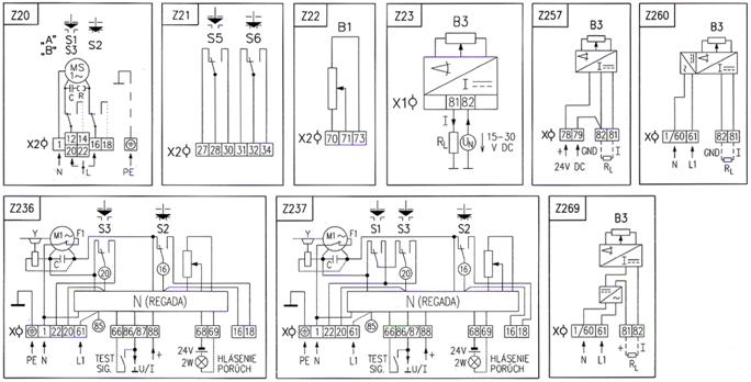
ST 0, STR 0 Wiring diagrams foe EA STR with controller ERROR ERROR TEST MESSAGE MESSAGE INDIC. Legend: Z20 ..electric motor with thrust and positional switches connection Z20g ..electric motor with thrust switches connection and space heater connection Z21 .. -
Page 28: Dimensional Drawings
ST 0, STR 0 6.2 Dimensional drawings EA ST, STR (The dimensions are valid also for the following dimensional drawings where only mechanical connection types are shown.)
-
Page 29
ST 0, STR 0 Flange DIN 3358… -
Page 30
ST 0, STR 0 Pillars… -
Page 31
ST 0, STR 0 Flange… -
Page 32
ST 0, STR 0 Flange… -
Page 33
ST 0, STR 0 Flange… -
Page 34
ST 0, STR 0 Pillars… -
Page 35
ST 0, STR 0 Flange… -
Page 36
ST 0, STR 0 Pillars… -
Page 37
ST 0, STR 0 Flange… -
Page 38
ST 0, STR 0 Flange… -
Page 39
ST 0, STR 0… -
Page 40
ST 0, STR 0… -
Page 41: Guarantee Service Check Report
ST 0, STR 0 6.3 Guarantee service check report Service center: Date of repair: Guarantee repair no.: User of actuator: Claim applied by: Actuator type number: Actuator production number: Product claim fault: Detected product fault: Used spare parts: Remarks: Issued on a day:…
-
Page 42: Post Guarantee Service Check Report
ST 0, STR 0 6.4 Post guarantee service check report Service center: Date of repair: User of actuator: Actuator operating place : Actuator type number: Actuator production number: Detected product fault: Used spare parts: Remarks: Issued on a day: Signature:…
-
Page 43: Commercial Representation
080 01 Prešov Tel.: +421 (0)51 7480 460, Fax: +421 (0)51 7732 096, E-mail: regada@regada.sk Czech Republic: Exclusive representation Regada, s.r.o. (Ltd.) for sale of electric actuators Regada Česká, s.r.o. Nám. 5. května 17, 252 25 Jinočany, PRAHA – západ, Tel.: +420 257 961 302…
This manual is also suitable for:
Str 0
-
Page 1
INSTALLATION, SERVICE AND MAINTENANCE INSTRUCTIONS Electric linear actuators ST 0, STR 0 ® 74 0813 02… -
Page 2
TEST CERTIFICATE ELECTRIC LINEAR THRUST ACTUATOR ST 0, STR 0 Type number 490……. Power supply ……V ..Hz Serial number ……..Max. load thrust ……….N Production year ……..Switching-off thrust ……..N Wiring diagram ……..Operation speed ………mm/min ………… -
Page 3: Table Of Contents
Please read these instructions carefully before mounting and operating the actuator! Contents General data …………………………2 Purpose and applications……………………2 Safety instructions……………………..2 Data specified on electric actuator………………..3 Warranty conditions …………………….. 3 Under-guarantee and after-guarantee service …………….. 3 Operation conditions ……………………. 4 Description ……………………….
-
Page 4: General Data
1. General data 1.1 Purpose and applications Electric linear actuators (hereinafter EA) of ST 0 (hereinafter ST) or STR 0 (hereinafter STR) types are high-powered electric-mechanical products designed for direct installations onto controlled devices (regulating bodies -valves, etc.). EA of ST types are provided for remote control of closing bodies, and EA of STR types for automotive control of regulating bodies in both directions of their movement.
-
Page 5: Data Specified On Electric Actuator
ST 0, STR 0 Instructions for operating stuff training Operation can be performed by skilled personel only trained by production plant, resp. by contracting service center! Warning for safety use Product protection EA ST, STR does not have own short-circuit protection, therefore there must be included suitable protective device into the supply power ( circuit breaker, or fuse), which serves at the same time as main switch.
-
Page 6: Operation Conditions
ST 0, STR 0 • type of fault — description of claimed fault (actuator employment, ambient parameters (temperature, humidity…), duty cycle including frequency of switching, type of switching-off (position or thrust), set switching-off thrust) • it is recommended to place also Installation certificate.
-
Page 7
ST 0, STR 0 1.6.2 Operation Environment According to valid standard IEC 60 721-2-1, there are delivered these versions of electric actuators: 1) Version „temperate“ for type climate temperate 2) Version „tropical“ for type climate tropical and dry 3) Version „marine“ for type climate marine. -
Page 8: Description
ST 0, STR 0 1.6.3 Power supply: electric motor …………… 230 / 220 V AC ±10%, or 24 V AC/DC ±10% control …………….. 230 / 220 V AC ±10%, or 24 V AC/DC ±10% potentiometer ………………..max. PxR V DC/AC electronic positional transmitter without power supply ……
-
Page 9: Basic Specifications
ST 0, STR 0 1.8 Basic specifications 1.8.1 Basic EA specifications Max. load thrust [N], switch-off thrust [N], operating speed [mm/min], operating stroke [mm] and electric motor parameters are given in Table 1. Table 1: Basic Specifications Operating Electric motor…
-
Page 10
ST 0, STR 0 EA protection enclosure: …………..IP 54 / IP67 (EN/IEC 60 529) Mechanical ruggedness: sinusoid vibrations ………………..see chapter 1.5.2 drop resistance:…………….300 drops with acceleration 5 m.s seismic resistance: …………amplitude of the shock off 6 on Richter scale Position transmitters Resistive –… -
Page 11
ST 0, STR 0 Electronic position controller (N) Controller software equipment: A) Function and parameters programmable functions: •..with functional buttons SW1, SW2 and LED diodes D1, D4 directly placed on controller •..with computer or terminal equipped with corresponding programme, using RS 232 interface. -
Page 12: Conservation, Packing, Transport, Storing And Unpacking
ST 0, STR 0 Adjustment of limit positions: Position switch S3 is adjusted to specified stroke. Limit position switches are adjusted with accuracy ± 0,5 mm referring to lower position and stroke. Additional position switches are adjusted 1mm before end positions.
-
Page 13: Appreciation Of The Product And Packing
ST 0, STR 0 temperature: -25°C up to +70°C humidity: 5 up to 100%, with maximal content of water 0.029 kg/kg per kg of dry air barometric pressure: 86kPa up to 108kPa After receiving EA check whether during transport or storage the actuator was not damaged.
-
Page 14: Installation
ST 0, STR 0 2.1 Installation EA is by the producer adjusted to parameters according to the nameplate, with connecting dimensions according to the corresponding dimensional drawing and put it to a mid-position. Before installation put the handle on. 2.1.1 Mechanical connection The actuators can be installed and operated in any position.
-
Page 15
ST 0, STR 0 Mechanical connection for pillar version — Fig. 3 Connection procedure: • The valve (B) is put to the position „closed“ and the actuator (A) to a mid-position. • Loosen the nuts (4) on the pillars (6). -
Page 16
ST 0, STR 0 Mechanical connection for versions with flange TGL (Fig. 5) Connection procedure: • Set the actuator (A) and the valve (B) to the position „closed“. • Place the actuator (A) onto the valve (B). • Tighten the clamp nuts (11) to connect flanges (13) and (5). -
Page 17: Dismantling
ST 0, STR 0 Connecting with the master system: The EA can be controlled with: • a built-in position controller • an external position controller The actuator is connected in accordance with the wiring diagrams put into the actuator upper cover.
-
Page 18: Gear Unit Adjustment
ST 0, STR 0 3.1 Gear unit adjustment The switching thrust values both for the direction „opening“ (the thrust switch S1) and for the direction „closing“ (the thrust switch S2) are in the production plant adjusted to the rated thrust with tolerance ±10%.
-
Page 19: Adjustment Of The Electronic Position Transmitter (Epv) — The Resistive Transmitter (Potentiometer) With The Converter Ptk 1
ST 0, STR 0 3.4 Adjustment of the Electronic Position Transmitter (EPV) — the Resistive Transmitter (Potentiometer) with the Converter PTK 1 The position transmitter with the converter is in the plant adjusted to have the output current signal on the terminals 81-82 as follows: •…
-
Page 20: Adjustment Of Position Controller (Fig. 9)
At values less than 85% the value of the output signal is reduced proportionally. 3.5 Adjustment of position controller (Fig. 9) The built-in position controller REGADA of new generation is a user-friendly control system to control actuators with an analogue signal. The controller takes…
-
Page 21
Adjust the position and thrust switches and the position transmitter before adjustment of the controller. Laying of adjusters and signalling elements on the board of the REGADA controller is shown on Fig. 9: SW1 button starts an initialisation routine an allows… -
Page 22
ST 0, STR 0 Controller setting procedure: The initialisation routine starts at the switched-on controller, zero system deviation and short pressing of the SW1 button for ca 2 sec (i.e. until the diode D3 got on). Loosing the button some of the default menus starts (usually control signal) what is shown with 1 blink on the D3 diode as well as one of the default parameters (usually control signal of 4-20mA) what is shown with 1 blink on the D4 diode. -
Page 23: Positions Of Jumbers Of Bidirectional (Reversing) Board For Supply Voltage 24V Dc ( Wiring Diagram Z216D)
ST 0, STR 0 3.6 Positions of jumbers of bidirectional (reversing) board for supply voltage 24V DC ( wiring diagram Z216d). Position jumper Position jumper JP1 Position jumper Fig. 10 Positions of jumpers of bidirectional (reversing) board 4. Service, maintenance and troubleshooting 4.1 Service…
-
Page 24: Maintenance — Extent And Periodicity
ST 0, STR 0 Manual control: If needed (during adjusting, function checking, failure etc.) the stuff can change setting of the controlled body using the handle. Instructions for manual control: • Switch the power supply off. • Turn the button for gear disengagement to the right by 90° (Fig. 10, the button arrow shows the symbol of hand) what disengages the gear in the actuator.
-
Page 25: Troubleshooting
ST 0, STR 0 4.3 Troubleshooting At failure of power supply the EA stops in the position where it was before the failure. If needed the EA can be set only with the manual control (the handle). After restoration of power the EA is prepared for operation.
-
Page 26: Enclosures
ST 0, STR 0 6. Enclosures 6.1 Wiring diagrams Wiring diagrams for EA ST…
-
Page 27
ST 0, STR 0 Wiring diagrams foe EA STR with controller ERROR ERROR TEST MESSAGE MESSAGE INDIC. Legend: Z20 ..electric motor with thrust and positional switches connection Z20g ..electric motor with thrust switches connection and space heater connection Z21 .. -
Page 28: Dimensional Drawings
ST 0, STR 0 6.2 Dimensional drawings EA ST, STR (The dimensions are valid also for the following dimensional drawings where only mechanical connection types are shown.)
-
Page 29
ST 0, STR 0 Flange DIN 3358… -
Page 30
ST 0, STR 0 Pillars… -
Page 31
ST 0, STR 0 Flange… -
Page 32
ST 0, STR 0 Flange… -
Page 33
ST 0, STR 0 Flange… -
Page 34
ST 0, STR 0 Pillars… -
Page 35
ST 0, STR 0 Flange… -
Page 36
ST 0, STR 0 Pillars… -
Page 37
ST 0, STR 0 Flange… -
Page 38
ST 0, STR 0 Flange… -
Page 39
ST 0, STR 0… -
Page 40
ST 0, STR 0… -
Page 41: Guarantee Service Check Report
ST 0, STR 0 6.3 Guarantee service check report Service center: Date of repair: Guarantee repair no.: User of actuator: Claim applied by: Actuator type number: Actuator production number: Product claim fault: Detected product fault: Used spare parts: Remarks: Issued on a day:…
-
Page 42: Post Guarantee Service Check Report
ST 0, STR 0 6.4 Post guarantee service check report Service center: Date of repair: User of actuator: Actuator operating place : Actuator type number: Actuator production number: Detected product fault: Used spare parts: Remarks: Issued on a day: Signature:…
-
Page 43: Commercial Representation
080 01 Prešov Tel.: +421 (0)51 7480 460, Fax: +421 (0)51 7732 096, E-mail: regada@regada.sk Czech Republic: Exclusive representation Regada, s.r.o. (Ltd.) for sale of electric actuators Regada Česká, s.r.o. Nám. 5. května 17, 252 25 Jinočany, PRAHA – západ, Tel.: +420 257 961 302…
Regada ST 0 Controller PDF User Guides and Manuals for Free Download: Found (1) Manuals for Regada ST 0 Device Model (Installation, Service And Maintenance Instructions)
More Controller Device Models:
-
YASKAWA
SI-P3V
MANUAL NO. TOBP C730600 23AType SI-P3/VTo properly use the product, read this manual thoroughly and retainfor easy reference, inspection, and maintenance. Ensure the end userreceives this manual.Installation ManualPROFIBUS-DPYASKAWA AC Drive-V1000 Option …
SI-P3V DC Drives, 34
-
YASKAWA
NX100
Motoman, Incorporated 805 Liberty LaneWest Carrollton, OH 45449TEL: (937) 847-6200FAX: (937) 847-627724-Hour Service Hotline: (937) 847-3200Motoman NX100 ControllerInterrupt JobFunction ManualPart Number: 149648-6CDRevision: 1 …
NX100 Controller, 36
-
BIFFI
ALGAS-MHW
Copyright © Bif. The information in this document is subject to change without notice. Updated data sheets can be obtained from our website www.bif.it or from your nearest Bif Center: Bif Italia s.r.l. — Strada Bif 165, 29017 Fiorenzuola d’Arda (PC) – Italy PH: +39 0523 944 411 – bif_italia …
ALGAS-MHW Industrial Equipment, 48
-
Festo
CPX Series
Electronics manualCPX I/O modulesPneumaticinterfaces type VMPA−FB−EPL−… CPX−GP−03−4.0 CPX−GP−CPA−… VABA−10S6−X1MPA pneumaticmodules withelectronic modulestype VMPA1−FB−EM..−8 VMPA2−FB−EM..−4I/O modules type CPX−8DE, −8DE−D, −4DE CPX−4DA, …
CPX Series Touch terminals, 208
Recommended Documentation:
TEST CERTIFICATE
ELECTRIC LINEAR THRUST ACTUATOR ST 0, STR 0
Type number 490. …………………………
Serial number ………………………………
Production year …………………………….
Wiring diagram ……………………………..
………………………………………………….
………………………………………………….
Warranty period ………………… months
Serial number of electric motor ………………………………………………………………………………..
Serial number of transmitter …………………………………………………………………………………….
Serial number of position controller …………………………………………………………………………..
Tests made in accordance with TP 74 0878 00
Tests made by ……………………………..
Date ……………………………………………
COMPLETENESS CERTIFICATE
Used valve …………………………………………………………………………………………………………..
Assembled by: Firm ………………………………………………………………………………………………
Name……………………………………………………………………………………………….
Warranty period ……………….. months
Date ………………………………………….
INSTALLATION CERTIFICATE
Location ………………………………………………………………………………………………………………
Installed by: Firm ………………………………………………………………………………………………….
Name ………………………………………………………………………………………………….
Warranty period………………… months
Date ………………………………………….
Power supply ………………………… V
Max. load thrust ……………………………………..N
Switching-off thrust …………………………………N
Operation speed ……………………………mm/min
Operating stroke ………………………………… mm
Input operation signal ……………………………….
Transmitter (potentiometer) ……………………….
Packed by ……………………………………………….
Signature and stamp …………………………………
Signature and stamp………………………………….
Signature and stamp………………………………….
……… Hz
- Regada ST mini — прямоходный электрический исполнительный механизм (ЭИМ) серии Standart
- Regada ST 0.1 — прямоходный электрический исполнительный механизм (ЭИМ) серии Standart
- Regada ST 1 — прямоходный электрический исполнительный механизм (ЭИМ) серии Standart
- Regada ST 2 — прямоходный электрический исполнительный механизм (ЭИМ) серии Standart
- Regada ST 1-Ех — прямоходный электрический исполнительный механизм (ЭИМ) во взрывозащищенном исполнении серии Standart-Ex
- Regada MT — прямоходный электрический исполнительный механизм (ЭИМ) во взрывозащищенном исполнении серии Standart-Ex
- Regada ST 0 — прямоходный электрический исполнительный механизм (ЭИМ) серии Standart
- Regada MT-Ех — прямоходный электрический исполнительный механизм (ЭИМ) во взрывозащищенном исполнении серии Standart-Ex
 серии Standart")
ЭИМ Regada являются исполнительными механизмами управления запорными и запорно-регулирующими клапанами, шаровыми кранами и затворами. Обеспечивают полное позиционное управление данными видами арматуры во всем диапазоне своих параметров.
Все приводы оснащены концевыми выключателями и муфтой ограничения крутящего момента.
Электроприводы расчитаны на работу в повторно-кратковременном режиме.
Цена по запросу!
- Характеристики
- Доставка и оплата
-
Характеристики
Характеристики ЭИМ прямоходный Regada ST-MT
Сервисное обслуживание
Мы являемся официальным сервисом по гарантийному, постгарантийному обслуживанию и ремонту электрических исполнительных механизмов (ЭИМ) компании Regada.
Специалисты САЗ «Авангард» окажут Вам профессиональную консультацию, быструю и эффективную техническую поддержку, ремонт ЭИМ. Вы можете быть уверены в качестве оказываемых услуг, так как мы используем только оригинальные запчасти от производителя. Все работы выполняются по технологии, рекомендованной производителем ЭИМ, и высококвалифицированными инженерами.
Гарантии
Гарантийный срок эксплуатации – 12 месяцев со дня ввода в эксплуатацию, но не более 18 месяцев со дня поставки, при соблюдении правил хранения, транспортировки, монтажа и эксплуатации.

-
Доставка и оплата
Способы
доставкиДоставка продукции осуществляется транспортными компаниями Деловые Линии, ПЭК, Желдорэкспедиция, Байкал-Сервис или
собственными автомобилями*:-
I. МАН (до 20 тонн)
-
II. Мерседес (до 20 тонн)
-
III. Хёндай (до 6,5 тонн)
-
IV. Газель (до 1,5 тонн)
* — цену доставки продукции уточняйте при оформлении.
Оплата
заказаЕсли продукция в наличии или срок изготовления 3-5 рабочих дней: предлагаем 100% предоплаты. Если срок изготовления
существенный: предлагаем 50% предоплаты, остальное – по факту готовности продукции к отгрузке. Возможны и иные способы
оплаты. -
наверх