-
Page 1
U S E R M A N U A L ACTUATOR LA36 To learn more about LINAK, please visit: w w w . l i n a k . c o m Page 1 of 76… -
Page 2
Page 2 of 76… -
Page 3: Table Of Contents
Contents Preface …………………………5 LINAK application policy ……………………6 Chapter 1 Safety instructions ……………………..7-8 Chapter 2 Mounting guidelines ……………………9-10 Mounting of cables ……………………..11 Electrical installation: ……………………..12 Actuator without feedback …………………..12 Actuator with: Endstop signal output ………………..13-14 Relative positioning — Dual Hall ………………. 15-16 Endstop signals and relative positioning — Dual Hall …………
-
Page 4
12V motor ………………………61 24V motor ………………………62 36V motor ………………………63 Label for LA36 ………………………64 Key to symbols ………………………64 LA36 Ordering example Econ ………………….65 LA36 Ordering example ……………………66 Chapter 5 Maintenance ……………………….67 Repair and spare parts ……………………67 Main groups of disposal ……………………67 Warranty ……………………….68… -
Page 5: Preface
LINAK provides a warranty on all its products. This warranty, however, is subject to correct use in accordance with the specifications, maintenance being done correctly and any repairs being carried out at a service centre, which is authorised to repair LINAK products.
-
Page 6: Linak Application Policy
LINAK shall be responsible solely that LINAK products comply with the specifications set out by LINAK and it shall be the responsibility of the LINAK customer to ensure that the specific LINAK product can be used for the application in question.
-
Page 7: Safety Instructions
Chapter 1 Safety instructions Please read this safety information carefully: Be aware of the following three symbols throughout the user manual: Warning! Failing to follow these instructions can cause accidents resulting in serious personal injury. Recommendations Failing to follow these instructions can result in the actuator suffering damage or being ruined.
-
Page 8
• Only use the actuator within specified working limits. • When mounting the LA36 in the application ensure that the bolts can withstand the wear and that they are secured safely. • If irregularities are observed, the actuator must be replaced. -
Page 9: Mounting Guidelines
In applications with high dynamic forces LINAK recommends not to use the fully extended or retracted position over longer time, as this can damage the endstop system permanently.
-
Page 10
It is the application manufacturer’s responsibility to incorporate a suitable safety arrangement, which will prevent personal injury from occurring, if the actuator should fail Warning! LINAK’s actuators are not designed for use within the following fields: • Offshore installations •… -
Page 11: Mounting Of Cables
1.5 ± 0.3 Nm TORX 25IP When changing the cables on a LINAK actuator, it is important that this is done carefully, in order to protect the plugs and pins. Before the new cable is mounted, we recommend that the socket is greased with vaseline, to keep the high IP protection and ensure an easy mounting.
-
Page 12: Electrical Installation
Electrical installation: Actuator without feedback: Connection diagram: Fig. 1 : 36xxxxx00/10xxxxxx 36xxxxxxx000xx-xxxxxxxxxxxxxxx BROWN BLUE I/O specifications: Input/Output Specification Comments Description Permanent magnetic DC motor. See connection diagram, fig. 1 above Brown 12, 24 or 36VDC (+/-) To extend actuator: Connect Brown to positive 12V ±…
-
Page 13: Endstop Signal Output
Actuator with endstop signal output: Connection diagram: Fig. 2 : 36xxxxx20xxxxxx 36xxxxxxx000xx-xxxxxxxxxxxxxxx BROWN BLUE YELLOW* GREEN* BLACK *YELLOW/GREEN: Endstop signals out are NOT potential free! If you wish to use the endstop signals, you will have to keep power on the brown, blue, red and black wires, otherwise the signal will be lost.
-
Page 14
Actuator with endstop signal output: I/O specifications: Input/Output Specification Comments Description The actuator can be equipped with electronically controlled endstop signals out. See connection diagram, fig. 2 on page 13 Brown 12, 24 or 36VDC (+/-) To extend actuator: Connect Brown to positive 12V ±… -
Page 15: Relative Positioning — Dual Hall
Actuator with relative positioning — Dual Hall: Connection diagram: Fig. 3 : 36xxxxx0H/1Hxxxxxx 36xxxxxxxH00xx-xxxxxxxxxxxxxxx BROWN BLUE YELLOW GREEN BLACK Page 15 of 76…
-
Page 16: Relative Positioning — Dual Hall
Overvoltage on the motor can per pulse result in shorter pulses. LA365A Actuator = 2.9 mm N.B. For more precise measure- per pulse ments, please contact LINAK A/S. Violet Not to be connected White Not to be connected Diagram of Dual…
-
Page 17: Endstop Signals And Relative Positioning — Dual Hall
Actuator with endstop signals and relative positioning — Dual Hall: Connection diagram: Fig. 4 : 36xxxxx2Hxxxxxx 36xxxxxxxH00xx-xxxxxxxxxxxxxxx BROWN BLUE VIOLET* WHITE* YELLOW GREEN BLACK *VIOLET/WHITE: Endstop signals out are NOT potential free! If you wish to use the endstop signals, you will have to keep power on the brown, blue, red and black wires, otherwise the signal will be lost.
-
Page 18
Overvoltage on the motor can mm per pulse result in shorter pulses. LA365A Actuator = 2.9 N.B. For more precise measure- mm per pulse ments, please contact LINAK A/S. Violet Endstop signal in Output voltage min. V — 2V Source current max. 30mA… -
Page 19: Relative Positioning — Single Hall
Actuator with relative positioning — Single Hall: Connection diagram: Fig. 5 : 36xxxxx0K/1Kxxxxxx 36xxxxxxxK00xx-xxxxxxxxxxxxxxx BROWN BLUE VIOLET BLACK Page 19 of 76…
-
Page 20
N.B. For more precise LA363B: Actuator = 0.3 mm per count measurements, please contact LA363A: Actuator = 0.4 mm per count LINAK A/S. LA365A: Actuator = 0.7 mm per count Low frequency with a high load. Frequency: Higher frequency with no load. -
Page 21: Endstop Signals And Relative Positioning — Single Hall
Actuator with endstop signals and relative positioning — Single Hall: Connection diagram: Fig. 6 : 36xxxxx2Kxxxxxx 36xxxxxxxK00xx-xxxxxxxxxxxxxxx BROWN BLUE YELLOW* GREEN* VIOLET BLACK *YELLOW/GREEN: Endstop signals out are NOT potential free! If you wish to use the endstop signals, you will have to keep power on the brown, blue, red and black wires, otherwise the signal will be lost.
-
Page 22: Endstop Signals And Relative Positioning — Single Hall
N.B. For more precise LA363B: Actuator = 0.3 mm per count measurements, please contact LA363A: Actuator = 0.4 mm per count LINAK A/S. LA365A: Actuator = 0.7 mm per count Low frequency with a high load. Frequency: Higher frequency with no load.
-
Page 23: Absolute Positioning — Analogue Feedback
Actuator with absolute positioning — Analogue feedback: Connection diagram: Fig. 7 : 36xxxxx1B/1Cxxxxxx 36xxxxxxxB00xx-xxxxxxxxxxxxxxx 36xxxxxxxC00xx-xxxxxxxxxxxxxxx BROWN BLUE VIOLET BLACK Page 23 of 76…
-
Page 24
Actuator with absolute positioning — Analogue feedback: I/O specifications: Input/Output Specification Comments Description The actuator can be equipped with electronic circuit that gives an analogue feedback signal when the actuator moves. See connection diagram, fig. 7, page 23 Brown 12, 24 or 36VDC (+/-) To extend actuator: Connect Brown to positive 12V ±… -
Page 25: Endstop Signals And Absolute Positioning — Analogue Feedback
Actuator with endstop signals and absolute positioning — Analogue feedback: Connection diagram: Fig. 8 : 36xxxxx2B/2Cxxxxxx 36xxxxxxxB00xx-xxxxxxxxxxxxxxx 36xxxxxxxC00xx-xxxxxxxxxxxxxxx BROWN BLUE YELLOW* GREEN* VIOLET BLACK *YELLOW/GREEN: Endstop signals out are NOT potential free! If you wish to use the endstop signals, you will have to keep power on the brown, blue, red and black wires, otherwise the signal will be lost.
-
Page 26
Actuator with endstop signals and absolute positioning — Analogue feedback: I/O specifications: Input/Output Specification Comments Description The actuator can be equipped with electronic circuit that gives an analogue feedback signal when the actuator moves. See connection diagram, fig. 8, page 25 Brown 12, 24 or 36VDC (+/-) To extend actuator:… -
Page 27: Absolute Positioning — Mechanical Potentiometer Feedback
Actuator with absolute positioning — Mechanical potentiometer feedback: Connection diagram: Fig. 9 : 36xxxxx0P/1Pxxxxxx 36xxxxxxxP00xx-xxxxxxxxxxxxxxx BROWN BLUE WHITE (VCC+ to POT) VIOLET BLACK Page 27 of 76…
-
Page 28: Absolute Positioning — Mechanical Potentiometer Feedback
Actuator with absolute positioning — Mechanical potentiometer feedback: I/O specifications: Input/Output Specification Comments Description The actuator can be equipped with a mechanical potentiometer, 10 kohm. See connection diagram, fig. 9, page 27 Bourns 0-10 kohm, 5%, 10-Turn Type: 3540 Wirewound Brown 12, 24 or 36VDC (+/-) To extend actuator:…
-
Page 29: Endstop Signals And Absolute Positioning — Mechanical Potentiometer Feedback
Actuator with endstop signals and absolute positioning — Mechanical potentiometer feedback: Connection diagram: Fig. 10 : 36xxxxx2Pxxxxxx 36xxxxxxxP00xx-xxxxxxxxxxxxxxx BROWN BLUE YELLOW* GREEN* WHITE (VCC+ to POT) VIOLET BLACK *YELLOW/GREEN: Endstop signals out are NOT potential free! If you wish to use the endstop signals, you will have to keep power on the brown, blue, red and black wires, otherwise the signal will be lost.
-
Page 30
Actuator with endstop signals and absolute positioning — Mechanical potentiometer feedback: I/O specifications: Input/Output Specification Comments Description The actuator can be equipped with a mechanical potentiometer, 10 kohm. See connection diagram, fig. 10, page 29 Bourns 0-10 kohm, 5%, 10-Turn Type: 3540 Wirewound Brown 12, 24 or 36VDC (+/-) -
Page 31: Absolute Positioning — Pwm
Actuator with absolute positioning — PWM: Connection diagram: Fig. 11 : 36xxxxx15/16xxxxxx 36xxxxxxxF00xx-xxxxxxxxxxxxxxx BROWN BLUE VIOLET BLACK Page 31 of 76…
-
Page 32: Absolute Positioning — Pwm
Actuator with absolute positioning — PWM: I/O specifications: Input/Output Specification Comments Description The actuator can be equipped with electronic circuit that gives an analogue feedback signal when the actuator moves. See connection diagram, fig. 11, page 31 Brown 12, 24 or 36VDC (+/-) To extend actuator: Connect Brown to positive 12V ±…
-
Page 33: Endstop Signals And Absolute Positioning — Pwm
Actuator with endstop signals and absolute positioning — PWM: Connection diagram: Fig. 12 : 36xxxxx25/26xxxxxx 36xxxxxxxF00xx-xxxxxxxxxxxxxxx BROWN BLUE YELLOW* GREEN* VIOLET BLACK *YELLOW/GREEN: Endstop signals out are NOT potential free! If you wish to use the endstop signals, you will have to keep power on the brown, blue, red and black wires, otherwise the signal will be lost.
-
Page 34
Actuator with endstop signals and absolute positioning — PWM: I/O specifications: Input/Output Specification Comments Description The actuator can be equipped with electronic circuit that gives an analogue feedback signal when the actuator moves. See connection diagram, fig. 12, page 33 Brown 12, 24 or 36VDC (+/-) To extend actuator:… -
Page 35: Old Cs36 (H-Bridge) Version — Dual Hall
Actuator with old CS36 (H-bridge) version — Dual Hall: Connection diagram: Fig. 13 : 36xxxxx30/3Hxxxxxx BROWN BLUE INWARDS VIOLET OUTWARDS WHITE H-Bridge YELLOW GREEN BLACK Page 35 of 76…
-
Page 36
Actuator with old CS36 (H-bridge) version — Dual Hall: I/O specifications: Input/Output Specification Comments Description The actuator can be equipped with old version of integrated controller. See connection diagram, H-Bridge fig. 13, page 35 Brown To extend actuator: Connect Brown to positive Only available with 24VDC (+/-) To retract actuator: 24V ±… -
Page 37: Old Cs36 (H-Bridge) Version — Endstop Signals
Actuator with old CS36 (H-bridge) version — Endstop signals: Connection diagram: Fig. 14 : 36xxxxx40xxxxxx BROWN BLUE INWARDS VIOLET OUTWARDS WHITE H-Bridge YELLOW* GREEN* BLACK *YELLOW/GREEN: Endstop signals out are NOT potential free! If you wish to use the endstop signals, you will have to keep power on the brown, blue, red and black wires, otherwise the signal will be lost.
-
Page 38
Actuator with old CS36 (H-bridge) version — Endstop signals: I/O specifications: Input/Output Specification Comments Description The actuator can be equipped with old version of integrated controller. See connection diagram, H-Bridge fig. 14, page 37 Brown To extend actuator: Connect Brown to positive Only available with 24VDC (+/-) To retract actuator: 24V ±… -
Page 39: Ic Basic
Actuator with IC Basic: Connection diagram: Fig. 15 : 36xxxxx7xxxxxxx 36xxxxxxxx03xx-xxxxxxxxxxxxxxx BROWN 12/24V DC BLUE INWARDS BLACK OUTWARDS H-Bridge FEEDBACK VIOLET Hall SIGNAL GND WHITE 0-10V Please be aware that if the power supply is not properly connected, you might damage the actuator! Page 39 of 76…
-
Page 40
Actuator with IC Basic: I/O specifications: Input/Output Specification Comments Description Easy to use interface with integrated power electronics (H-bridge). The actuator can also be equipped with electronic circuit that gives an absolute or relative feedback signal. The version with “IC option” H-Bridge cannot be operated with PWM (power supply). -
Page 41
Actuator with IC Basic: I/O specifications: Input/Output Specification Comments Violet Analogue feedback Standby power consumption: 12V, 60mA 0-10V (Option 7.2) 24V, 45 mA Ripple max. 200mV Transaction delay 20ms Linear feedback 0.5% Max. current output: 1mA It is recommendable to have the actuator to activate its limit switches on a regular basis, to ensure more precise positioning… -
Page 42: Ic Advanced — With Buslink
BusLink is available for IC Advanced and can be used for: Diagnostics, manual run and configuration Download BusLink software here: http://www.linak.com/techline/?id3=2363 For more information and easy set-up of BusLink, please follow this link to view the Quick Guide for BusLink: http://www.linak.com/techline/?id3=2356…
-
Page 43
Actuator with IC Advanced — with BusLink: I/O specifications: Input/Output Specification Comments Description Easy to use interface with integrated power electronics (H-bridge). The actuator can also be equipped with electronic circuit that gives an absolute or relative feedback signal. IC Advanced provides a wide range of possibilities for customisation. -
Page 44: Ic Advanced — With Buslink
Actuator with IC Advanced — with BusLink: I/O specifications: Input/Output Specification Comments Violet Analogue feedback (0-10V): Ripple max. 200mV Configure any high/low Transaction delay 20ms combination between 0-10V Linear feedback 0.5% Max. current output. 1mA Single Hall output (PNP) Output voltage min. V — 2V Max.
-
Page 45: Correct Wiring Of Power Gnd And Signal Gnd For Ic Basic And Ic Advanced
Power supply BLUE POWER GND Control connector Hall VIOLET FEEDBACK 0-10V Feedback input WHITE SIGNAL GND 4-20mA LA36 IC actuator Please note that this section only applies for the following feedback options: 0-10V, Hall and PWM. Page 45 of 76…
-
Page 46: Actuator With Parallel
Actuator with Parallel: Connection diagram: Fig. 17 : 36xxxxx9xxxxxxx 36xxxxxxxx03xx-xxxxxxxxxxxxxxx Actuator 8 Actuator 7 Actuator 6 Actuator 5 Actuator 4 Actuator 3 Actuator 2 Actuator 1 BROWN 12/24V DC Communi- cation Communi- BLUE cation Communi- cation Communi- cation Communi- VIOLET cation Communi- cation…
-
Page 47
Actuator with Parallel: I/O specifications: Input/Output Specification Comments Description Parallel drive of up to 8 actuators. A master actuator with an integrated H-bridge controller controls up to 7 slaves. H-Bridge The version with “IC option” H-Bridge cannot be operated with PWM (power supply). -
Page 48
Actuator with Parallel: I/O specifications: Input/Output Specification Comments Green Endstop signal out Output voltage min. V — 2V Source current max. 100mA Yellow Endstop signal in NOT potential free Violet Parallel communication: Standby power consumption: Violet cords must be connected 12V, 60mA together 24V, 45mA… -
Page 49: The Parallel System
The parallel system: The parallel drive function will support a number of actuators working jointly. The system is self-configurable and when connected, a Master will be dedicated. The Master will then control up to 7 slaves. It is both possible to run parallel with a single power supply, or to run each actuator with separate power supplies.
-
Page 50: The Parallel System
The broken actuator needs to be replaced, before the system can run again. The system will only run, when it is complete • If you need to add an additional actuator to the parallel system, please contact your local LINAK supplier. The system will need to be re-programmed BusLink is available for Parallel •…
-
Page 51: System Monitoring For Parallel
System Monitoring for Parallel If one of the actuators have one of the following error conditions, the actuator will immediately STOP: • H-Bridge fault • Out of the temperature range (High duty cycle protection) • Overcurrent (Current cut-off if one or all actuators go in mechanical block) •…
-
Page 52: Troubleshooting
• Check wire connection (Red/ Wrongly connected: Black) on control unit + Brown, — Blue Signal required for moving • Please contact LINAK outwards: + VCC -> RED Wire Signal required for moving inwards: + VCC -> Black Wire Excessive electricity Misalignment or overload in •…
-
Page 53: Troubleshooting
Connect actuator to BusLink and to BusLink check current parameters. Initialise the actuator in both directions • Please contact LINAK Motor runs too slowly Load is higher than specified • Reduce load or does not run with Voltage drop in cable (Use of long…
-
Page 54: Troubleshooting For Parallel
Troubleshooting for Parallel: Symptom Possible cause Action No actuators in Power supply • Check power supply source and movement power connections: Brown + Blue — Please be aware that if the power supply is not properly connected, you might damage the actuator Signal connections •…
-
Page 55
Troubleshooting for Parallel: Symptom Possible cause Action Signal cable damaged All actuators stop at the same • When seeing a communication or removed under position error, the system goes into operation ‘position lost’ • The signal and power cables MUST be connected to all actuators again •… -
Page 56: Troubleshooting For Parallel
In/Out signals must be removed before next movement For more information and easy set-up of BusLink, please follow this link to view the Quick Guide for BusLink: http://www.linak.com/techline/?id3=2356 Be aware of Modbus actuator — please see the Modbus installation guide. http://www.linak.com/techline/?id3=2363…
-
Page 57: Specifications
Safety device regarding functional failure of the nut (Safety nut): The LA36 has a built-in safety nut in push as an option. Actuators with safety nut in push can only function when used in push applications. The safety nut comes into operation should the main nut fail.
-
Page 58: Actuator Dimensions
Actuator dimensions TECHLINE LA36: ® 01= Standard ST R O KE <= 3 0 0 = 200 + STR OKE ST R O KE => 30 0 = 250 + STRO KE 02= Turned 90° 02= Turned 90˚ 01= Standard S TR OKE <= 30 0 = 18 8 + S TR O KE…
-
Page 59: Built-In Dimensions
Built-in dimensions Piston rod “0” /from the surface “1” / to the centre of “2” / to the centre of “3” / from the surface the hole the hole Back fixture Stroke <=300 Stroke Stroke <=300 Stroke Stroke <=300 Stroke Stroke <=300 Stroke >…
-
Page 60: Manual Hand Crank
Manual Hand Crank The manual hand crank can be used in the case of power failure. 6 mm Allen key The cover over the Allen key socket must be unscrewed before the Allen key can be inserted and the hand crank operated. Hand Crank Torque: 6 — 8 Nm Piston rod movement per turn, app.: 8 mm…
-
Page 61: Speed And Current Curves
Speed and current curves — 12V motor The values below are typical values and made with a stable power supply and an ambient tem- perature of 20˚C. LA36 12V motor current vs. load 20mm/ 8mm/ 12mm/ F gear 12mm/ 12mm/…
-
Page 62: Motor
Speed and current curves — 24V motor The values below are typical values and made with a stable power supply and an ambient tem- perature of 20˚C. LA36 24V motor current vs. load 20mm 20mm/ 12mm/ 12mm/ 8mm/ 12mm/ E gear…
-
Page 63: Motor
Speed and current curves — 36V motor The values below are typical values and made with a stable power supply and an ambient tem- perature of 20˚C. LA36 36V motor current vs. load 12mm/ 8mm/ 20mm/ 12mm/ 20mm/ 12mm/ H gear…
-
Page 64: Label For La36
7. W/O #1234567-0001 The LINAK work order followed by a unique sequential identification number Key to symbols: The following symbols are used on the LA36 label:…
-
Page 65: La36 Ordering Example Econ
Safety : A = Safety nut Stroke Length: XXX = mm. Spindle Pitch: 080 = 8 mm 120 = 12 mm 200 = 20 mm Actuator Type: 36 = LA36 IC options: LINbus Modbus Parallel � � � � LA36 actuator:…
-
Page 66: La36 Ordering Example
LA36 0 = No cable COMBINATION CODE NOS. LA36 Ordering example 1 = 1.5 m power cable (0367046-1500) 2 = 5 m power cable (0367046-5000) 36 0 0 0 0 + 0 0 0 0 0 0 3 = 0.2 m power cable with AMP connector…
-
Page 67: Maintenance
If a system is opened by unauthorised personel there is a risk that it may malfunction at a later date. Spare parts LINAK can supply spindle parts and motor parts as spare parts. Please indicate the designation from the label when ordering spare parts from your nearest authorised LINAK dealer.
-
Page 68: Warranty
There is an 18 months’ warranty on TECHLINE products against manufacturing faults calculated from the production date of the individual products (see label). LINAK’s warranty is only valid in so far as the equipment has been used and maintained correctly and has not been tampered with. Furthermore, the actuator must not be exposed to violent treatment.
-
Page 69: Declarations Of Conformity
Smedevænget 8 DK — 6430 Nordborg hereby declares that LINAK Actuator 36xxxxx0xxxxxx, 36xxxxx1xxxxxx, 36xxxxx2xxxxxx, 36xxxxx5xxxxxx complies with the EMC Directive: 2014/30/EU according to following standards: EN 55016-2-1:2009, EN 55016-2-3:2010+A1+AC, EN 55022:2011+AC Class B, EN 55025:2008 EN 61000-4-2:2009, ISO 10605:2008, EN 61000-4-3:2006+A1, ISO 11452-2:2004, EN 61000-4-5:2006,…
-
Page 70
Smedevænget 8 DK — 6430 Nordborg hereby declares that Actuator 36xxxxxADxxxBxx (LA36 BUS) complies with the EMC Directive: 2014/30/EU according to following standards: EN 61000-6-1:2007, EN 61000-6-2:2005, EN 61000-6-3:2007, EN 61000-6-4:2007 complies with RoHS2 Directive 2011/65/EU according to the standard:… -
Page 71: Declarations Of Conformity
DECLARATION OF CONFORMITY LINAK A/S Smedevænget 8 DK — 6430 Nordborg Hereby declares that Actuator LA36IC (36xxxxx7xxxxxxx, 36xxxxx8xxxxxxx, 36xxxxx9xxxxxxx, 36xxxxxBxxxxxxx) LA36IC (36xxxxxxxx03xxxxxxxxxxxxxxxxxx) complies with the EMC Directive 2014/30/EU according to following harmonized standards: EN 61000-4-2:2009, EN 61000-4-3:2006+A1+A2, EN 61000-4-4:2012, EN 61000-4-5:2014, EN 61000-4-6:2014, EN…
-
Page 72: Declaration Of Incorporation Of Partly Completed Machinery
Linear Actuators LA12, LA14, LA22, LA23, LA25, LA30, LA35, LA36, LA37 comply with the following parts of the Machinery Directive 2006/42/EC, ANNEX I, Essential health and safety requirements relating to the design and construction of machinery: 1.5.1 Electricity supply…
-
Page 73
Page 73 of 76… -
Page 74
Page 74 of 76… -
Page 75
Page 75 of 76… -
Page 76: Adresses
LINAK. INDIA All sales are subject to the Standard Terms of Sale and Delivery for LINAK. Mechatronics Control Equipments India Pvt Ltd For a copy hereof, please contact LINAK. Phone: +91-44-28558484/85, E-mail: bala@mechatronicscontrol.com…
- PDF Viewer
- Universal Document Viewer
- Google Docs View
- Google Drive View
- Download Document [pdf]Not Your Device? Search For Manuals / Datasheets:
File Info : application/pdf, 20 Pages, 1.10MB
Document
homeline cbh basic systems user manual eng
USER MANUAL CBH Basic systems To learn more about LINAK please visit: W W W. L I N A K . C O M Page 1 of 20 Page 2 of 20 Contents Preface................................................................................................................................................................... 4 Valid for................................................................................................................................................................. 5 Important information......................................................................................................................................... 6 Safety instructions............................................................................................................................................ 6 Safety issues..................................................................................................................................................... 7 Before installation, re-installation or troubleshooting........................................................................................ 8 Before Start-up................................................................................................................................................. 8 Repairs................................................................................................................................................................. 10 Manufacturer's declaration................................................................................................................................ 10 Misc. on the HOMELINE® system....................................................................................................................... 11. Warranty........................................................................................................................................................ 11 Maintenance.................................................................................................................................................. 11 ETL-marking......................................................................................................................................................... 11 Description of the HOMELINE® CBH Basic system............................................................................................ 12 Mounting guideline for the CBH..................................................................................................................... 12 Cable relief.................................................................................................................................................... 13 Disposal of LINAK's products ............................................................................................................................ 14 Main groups of disposal .................................................................................................................................... 14 Disposal of batteries........................................................................................................................................... 14 Labels................................................................................................................................................................... 15 Drawings............................................................................................................................................................. 16 Addresses............................................................................................................................................................ 20 Page 3 of 20 Preface We are delighted that you have chosen a product from LINAK®. LINAK systems are high-tech products based on many years of experience in the manufacture and development of actuators, electric control boxes, controls and chargers. This User Manual does not address the end-user. It is intended as a source of information for the manufacturer of the equipment or system only, and it will tell you how to install, use and maintain your LINAK electronics. It is the responsibility of the manufacturer of the end-use product to provide a User Manual where relevant safety information from this manual is passed on to the end-user. We are sure that your LINAK product/system will give you many years of problem-free operation. Before our products leave the factory they undergo full function and quality testing. Should you nevertheless experience problems with your LINAK product/system, you are always welcome to contact your local dealer. LINAK subsidiaries and some distributors situated all over the world have authorised service centres, which are always ready to help you. LINAK provides a warranty on all its products. This warranty, however, is subject to correct use in accordance with the specifications, maintenance being done correctly and any repairs being carried out at a service centre, which is authorised to repair LINAK products. Changes in installation and use of LINAK products/systems can affect their operation and durability. The products are not to be opened by unauthorised personnel. The User Manual has been written based on our present technical knowledge. We are constantly working on updating the information and we therefore reserve the right to carry out technical modifications. LINAK A/S Page 4 of 20 Valid for: This User Manual is valid for the following products: (See the first 3 - 5 characters on the label) Actuators: Control box: Power supply: Controls: LA27, KA20 CBH1200B SMPS001 or SMPS002 HB10, HBBRIO02 Page 5 of 20 Important information Important information on LINAK® products can be found under the following headings: Warning! Failure to comply with these instructions may result in accidents involving serious personal injury. Failing to follow these instructions can result in the product being damaged or being destroyed. Safety instruction General Safe use of the system is possible only when the operating instructions are read completely and the instructions contained are strictly observed. Failure to comply with instructions marked with the "NOTE" symbol may result in serious damage to the system or one of its components. It is important for everyone who is to connect, install, or use the systems to have the necessary information and access to this User Manual. Follow the instructions for mounting risk of injury if these instructions are not followed. The appliance is not intended for use by young children or infirm persons without supervision. If there is visible damage on the product it must not be installed. Note that during construction of applications, in which the actuator is to be fitted, there must be no possibility of personal injury, for example the squeezing of fingers or arms. Only the power supply type SMPS001 or SMPS002, shall be used with the system (CBH basic System). The power supply shall not be covered while operating to allow sufficient cooling of this appliance. Page 6 of 20 ...to be continued The appliance is only to be used with the power supply unit provided with the appliance. Furthermore take care about the connecting wires from the power supply to the CBH Basic System, don't damage this by overrun. Assure free space for movement of application in both directions to avoid blockade. Safety issues The builder of the equipment shall ensure that the use of the component complies with relevant standards like the Machine Directive. Care must be taken to avoid squeezing of cables as it can cause movement of the system! The SMPS001/002 must not be packed in heat insulating material, but must be placed so that it can emit waste heat to the surroundings. There are no ventilation holes to consider, the SMPS emits heat through its surface. Only the power supply type SMPS001 or SMPS002, or similar suited products meeting the requirements EN 60335-1, shall be used with the system (CBH basic System). Please observe that the actuators LA27 used for CBH Basic systems are with signal end-stop switches and are not compatible with CBH Advanced systems The SMPS006 is not compatible with the CBH Basic system. The system is only released to 24V DC (SMPS006 = 29V DC) It is possible only to use 1 power supply (SMPS001 or SMPS002) for 2 CBH systems. Remember speed may decrease when running 2 systems at the same time. Page 7 of 20 Before installation, re-installation, or troubleshooting: · Stop the actuators · Pull out the mains plug. · Relieve the actuators of any loads, which may be released during the work. Before start-up: · Make sure that the system has been installed as instructed in this User Manual. · Make sure that the voltage of the control box/SMPS is correct before the system is connected to the mains. · System connection. The individual parts must be connected before the control box/SMPS is connected to the mains. See the User Manual for LINAK actuators, if necessary. During operation · If the control box makes unusual noise or smells, switch off the mains voltage immediately. · Take care that the cables are not damaged. · The products must only be used in an environment, that corresponds to their IP protection. Misc. The actuator system has a sound level below 70dB(A) in typical applications. Updated manuals and declarations can always be found here: www.linak.com/homeline Page 8 of 20 Only for EU markets This appliance can be used by children aged from 8 years and above and persons with reduced physical, sensory or mental capabilities or lack of experience and knowledge if they have given supervision or instruction concerning use of the appliance in a safe way and understand the hazards involved. Children shall not play with the appliance. Cleaning and user maintenance shall not be made by children without supervision. Only for Non EU markets Persons who do not have the necessary experience or knowledge of the product/products must not use the product/products. Besides, persons with reduced physical, sensory or mental abilities must not use the product/products, unless they are under surveillance or they have been thoroughly instructed in the use of the apparatus by a person who is responsible for the safety of these persons. Moreover, children must be under surveillance to ensure that they do not play with the product. Misuse Do not overload the actuators this can cause danger of personal injury and damage to the system. Do not use the actuator system for lifting persons. Do not sit or stand on a table while operating risk of personal injury. Do not use the system in environments other than the intended indoor use Page 9 of 20 Repairs In order to avoid the risk of malfunction, all HOMELINE® repairs must only be carried out by authorised LINAK® workshops or repairers, as special tools must be used and special gaskets must be fitted. Lifting units under warranty must also be returned to authorised LINAK workshops. Warning! If any of the HOMELINE® products are opened, there will be a risk of subsequent malfunction. DECLARATION OF INCORPORATION OF PARTLY COMPLETED MACHINERY LINAK A/S Smedevænget 8 DK - 6430 Nordborg Herewith declares that LINAK HOMELINE® products as characterized by the following models and types: Control Boxes CB7, CB9H, CBH Advanced, CBH Basic And Linear Actuators Dual Actuators LA27, LA27CS, LA28, LA29, LA31 HOMELINE TD1, TD3 And Controls HB10, HB10RF, HB20, HB20RF, HB40, HB60, HC10, HC10RF, HC20RF, And Accessories DC CONNECTOR, DJBH, LED Lightbox, Lightplug001, Massage Motor, SMPS001, SMPS002, TR6, USB Connector comply with the following parts of the Machinery Directive 2006/42/EC, ANNEX I, Essential health and safety requirements relating to the design and construction of machinery: 1.5.1 Electricity supply The relevant technical documentation is compiled in accordance with part B of Annex VII and that this documentation or part hereof will be transmitted by post or electronically to a reasoned request by the national authorities. This partly completed machinery must not be put into service until the final machinery into which it is to be incorporated has been declared in conformity with the provisions of the Machinery Directive 2006/42/EC where appropriate. Nordborg, 2014-10-09 LINAK A/S John Kling, B.Sc.E.E. Certification and Regulatory Affairs Authorized to compile the relevant technical documentation Original Declaration Page 10 of 20 Misc. on the HOMELINE® system Warranty There is a 36 months' warranty on the HOMELINE products CBH Basic Systems against manufacturing faults from the production date of the individual products (see label). LINAK A/S' warranty is only valid in so far as the equipment has been used and maintained correctly and has not been tampered with. Furthermore, the system must not be exposed to violent treatment. In the event of this, the warranty will be ineffective/invalid. For further details, please see LINAK A/S' ordinary conditions of sale. Maintenance Clean dust and dirt on the outside of the system at appropriate intervals and inspect for damage and breaks. Inspect the connections, cables, and plugs and check for correct functioning as well as fixing points. The cleaners and disinfectants must not be highly alkaline or acidic (pH value 6-8). ETL-marking Due to space limitations, the complete ETL-marking demands are not represented on the marking plates. The full ETL Recognized Component markings are shown here. C/N 120690 Conforms to UL962 Cert. to CSA Std. C22.2 No. 68-09 ETL Recognized Component mark for Canada and United States C/N 9901916 Conforms to UL962 Cert. to CSA Std. C22.2 No. 68-09 ETL Recognized Component mark for Canada and United States C/N 4008003 Conforms to UL962 Cert. to CSA Std. C22.2 No. 68-09 ETL Recognized Component mark for Canada and United States C/N 4008005 Conforms to UL962 Cert. to CSA Std. C22.2 No. 68-09 ETL Recognized Component mark for Canada and United States C/N 4008671 Conforms to UL962 Cert. to CSA Std. C22.2 No. 68-09 ETL Recognized Component mark for Canada and United States Page 11 of 20 Description of the HOMELINE® CBH Basic system A CBH Basic system consists of: · CBH Basic control box · SMPS001 or SMPS002 power supply · LA27 linear actuator · HB10 handset Mounting guidelines for the CBH The control box is to be fastened with 2 screws with a head diameter between ø 8 and ø 10 mm. With regard to the surface pressure, ø 10 mm is preferable. See drawing for placing of mounting holes and the space the CBH takes up. The mounting surface to which the control box is attached should have a surface evenness better than ± 0.5 mm. The mounting screws on the control box must be fastened with a max. torque of 1 Nm. The CBH must not be packed in heat insulating material, but must be placed so that it can emit waste heat to the surroundings. There are no ventilation holes to consider, the CBH emits heat through its surface. The electric connection: The system is to be connected as follows: · Each linear actuator must be connected to the socket on the control box by means of the motor cable, which has a 6-pin plug in each end. · The control is to be connected on the opposite same side of the control box as the actuators. · Finally, connect the SMPS unit to the CBH via a DC port. Please note that the control box/SMPS must only be connected to the voltage stated on the labels. The LA27 actuator is a powerful actuator designed for applications such as leisure beds. Mechanical spline: The splines function so that the actuator can only push, not pull. During pull in the actuator, the inner tube is lifted off the thread bush, and the actuator can therefore never pull a load, only push. Functional test of mechanical splines: When the piston rod is at the innermost position, it must be possible to pull it out manually to its full travel length and to press it in again without much resistance and without using the motor. If this is not possible, contact your nearest LINAK dealer. Usage: · Duty cycle: 2/18; 2 minutes continuous use followed by 18 minutes not in use · Ambient temperature: +5oC to +40oC (the actuator must also be at this temp.) Warning! · If the actuator does not work as described above, the risk of injury due to squeezing can arise. The actuator must therefore immediately be sent for service at the nearest, authorised LINAK workshop. · Do only use the actuator within specified working limits. · Do not sideload the actuator. Page 12 of 20 Cable relief: The CBH features a cable relief option. By using these small holes on the CBH, you can tie the DC cables from the SMPS unit to the control box by use of standard cable ties. The circles illustrate the small holes on the control box where a standard cable tie can be mounted and the DC cable from the SMPS/Handset cable can be fixed. The extra cable tie length is just cut off when the cables have been fixed. The CBH is a ZEROTM control box A hallmark of the CBH ZERO platform is the very low power consumption in standby mode, saving energy and money. The low standby consumption is standard. Page 13 of 20 Disposal of LINAK's products As LINAK's customers often ask us how our products can be disposed of or scrapped we have prepared this guidance that enables a classification to different waste fractions for recycling or combustion. Guidance We recommend that our products be disassembled as much as possible and divided into different waste groups for recycling or combustion. For example, waste can be sorted into metals, plastics, cable scrap, combustible material and recoverable resources. Some of these main groups can be further divided into subgroups; e.g. metal can be divided into steel/ aluminium/copper and plastic can be divided into ABS/PA/PE/PP. As an example, the table below breaks down the different components in LINAK products to various recycling groups: Product Components Recycling group Column/ Actuator : Spindle and motor Plastic housing Cable PC boards Metal scrap Plastic recycling or combustion Cable scrap or combustion Electronics scrap Control Box : PC boards Plastic housing Cable Transformer Electronics scrap Plastic recycling or combustion Cable scrap or combustion Metal scrap Handset/Control : Plastic housing Cable PC boards Plastic recycling or combustion Cable scrap or combustion Electronics scrap By now, almost all our casted plastic parts are supplied with an interior code for plastic types and fibre contents, if any. Main groups of disposal Product main groups Metal scrap LA27, KA20 X CBH1200B SMPS001, SMPS002 HB10, HBBRIO02 Cable scrap Electronics scrap X X X X X X Plastic recycling or combustin X X X X Comments Disposal of batteries Details regarding safe disposal of used and leaking batteries: Batteries should be disposed in accordance with appropriate federal, state and local regulations. LINAK recommends that used or leaking batteries are disposed through local recycling systems. Please do not throw used or leaking batteries in normal household waste or in nature. This will cause damage to the enviroment. How to deal with leaking batteries Leaking batteries should be disposed as described above. If leaking batteries are discovered in the product, the batteries must be removed at once to minimise damage to the product. If leaking batteries are left in the product, it might become defective. It is recommended to use plastic gloves when handling leaking batteries. The contents of leaking batteries can cause chemical burns and respiratory irritation. If exposed to the contents of a leaking battery, please wash with soap and water. If irritation persists, please seek medical attention. In case of eye contact, please flush eyes thoroughly with water for 15 minutes and seek medical attention. Page 14 of 20 Labels Label for CBH Basic Label for LA27 Label for SMPS001 Label for SMPS002 Label for the Handset HB12 Page 15 of 20 DRAWING APPENDIX CBH Basic Page 16 of 20 SMPS001 SMPS002 Page 17 of 20 LA27 HB 10 with cable Drawing no.:LA27001B Page 18 of 20 LINAK APPLICATION POLICY The purpose of the application policy is to define areas of responsibilities in relation to applying a LINAK product defined as hardware, software, technical advice, etc. related to an existing or new customer application. LINAK products as defined above are applicable for a wide range of applications within the Medical, Furniture, Desk and Industry areas. Yet, LINAK cannot know all the conditions under which LINAK products will be installed, used, and operated, as each individual application is unique. The suitability and functionality of the LINAK product and its performance under varying conditions (application, vibration, load, humidity, temperature, frequency, etc.) can only be verified by testing, and shall ultimately be the responsibility of the LINAK customer using any LINAK product. LINAK shall be responsible solely that the LINAK products comply with the specifications set out by LINAK and it shall be the responsibility of the LINAK customer to ensure that the specific LINAK product can be used for the application in question. Page 19 of 20 FACTORIES CHINA LINAK (Shenzhen) Actuator Systems, Ltd. Phone: +86 755 8610 6656 Fax: +86 755 8610 6990 E-mail: sales@linak.cn www.linak.cn DENMARK LINAK A/S - Group Headquarters, Guderup Phone: +45 73 15 15 15 Fax: +45 74 45 80 48 Fax: +45 73 15 16 13 (Sales) E-mail: info@linak.com www.linak.com SLOVAKIA LINAK Slovakia s.r.o. Phone: +421 51 75 63 414 Fax: +421 51 75 63 410 E-mail: jp@linak.sk www.linak.com USA LINAK U.S. Inc. North and South American Headquarters Phone: +1 502 253 5595 Fax: +1 502 253 5596 E-mail: info@linak-us.com www.linak-us.com SUBSIDIARIES AUSTRALIA LINAK Australia Pty. Ltd Phone: +61 3 8796 9777 Fax: +61 3 8796 9778 E-mail: sales@linak.com.au www.linak.com.au DENMARK LINAK Danmark A/S Phone: +45 86 80 36 11 Fax: +45 86 82 90 51 E-mail: linak@linak-silkeborg.dk www.linak.dk ITALY LINAK Italia S.r.l. Phone: +39 02 48 46 33 66 Fax: +39 02 48 46 82 52 E-mail: info@linak.it www.linak.it AUSTRIA LINAK Repräsentanz Österreich (Wien) Phone: +43 (1) 890 7446 Fax: +43 (1) 890 744615 E-mail: info@linak.de www.linak.at FINLAND LINAK OY Phone: +358 10 841 8700 Fax: +358 10 841 8729 E-mail: linak@linak.fi www.linak.fi JAPAN LINAK K.K. Phone: 81-45-533-0802 Fax: 81-45-533-0803 E-mail: linak@linak.jp www.linak.jp BELGIUM & LUXEMBOURG LINAK Actuator-Systems NV/SA Phone: +32 (0)9 230 01 09 Fax: +32 (0)9 230 88 80 E-mail: beinfo@linak.be www.linak.be FRANCE LINAK France E.U.R.L Phone: +33 (0) 2 41 36 34 34 Fax: +33 (0) 2 41 36 35 00 E-mail: linak@linak.fr www.linak.fr MALAYSIA LINAK Actuators Sdn. Bhd. Phone: +60 4 210 6500 Fax: +60 4 226 8901 E-mail: info@linak-asia.com www.linak.my BRAZIL GERMANY LINAK Do Brasil Comércio De Atuadores Ltda. LINAK GmbH Phone: +55 (11) 2832 7070 Phone: +49 6043 9655 0 Fax: +55 (11) 2832 7060 Fax: +49 6043 9655 60 E-mail: info@linak.com.br E-mail: info@linak.de www.linak.com.br www.linak.de NETHERLANDS LINAK Actuator-Systems B.V. Phone: +31 76 5 42 44 40 Fax: +31 76 5 42 61 10 E-mail: info@linak.nl www.linak.nl CANADA LINAK Canada Inc. Phone: +1 502 253 5595 Fax: +1 416-255-7720 E-mail: info@linak.ca www.linak-us.com INDIA LINAK A/S India Liaison Office Phone: +91 120 4393335 Fax: +91 120 4273708 E-mail: info@linak.in www.linak.in NEW ZEALAND LINAK New Zealand Ltd. Phone: +64 9580 2071 Fax: +64 9580 2072 E-mail: nzsales@linak.com.au www.linak.co.nz CZECH REPUBLIC LINAK C&S S.R.O. Phone: +420581741814 Fax: +420581702452 E-mail: ponizil@linak.cz www.linak.cz IRELAND LINAK UK Limited - Ireland Phone: +44 (0)121 544 2211 Fax: +44 (0)121 544 2552 +44 (0)796 855 1606 (UK Mobile) +35 387 634 6554 (Republic Of Ireland Mobile) E-mail: sales@linak.co.uk www.linak.co.uk NORWAY LINAK Norge AS Phone: +47 32 82 90 90 Fax: +47 32 82 90 98 E-mail: info@linak.no www.linak.no POLAND LINAK Polska Phone: +48 (22) 500 28 74 Fax: +48 (22) 500 28 75 E-mail: dkreh@linak.dk www.linak.pl REPUBLIC OF KOREA LINAK Korea Ltd. Phone: +82-(0)2-6231-1515 Fax: +82-(0)2-6231-1516 E-mail: scully@linak.kr www.linak.kr RUSSIAN FEDERATION 000 LINAK Phone: +7 495 280 14 26 Fax: +7 495 687 14 26 E-mail: info@linak.ru www.linak.ru SPAIN LINAK Actuadores, S.L.u Phone: +34 93 588 27 77 Fax: +34 93 588 27 85 E-mail: esma@linak.es www.linak.es SWEDEN LINAK Scandinavia AB Phone: +46 8 732 20 00 Fax: +46 8 732 20 50 E-mail: info@linak.se www.linak.se SWITZERLAND LINAK AG Phone: +41 43 388 31 88 Fax: +41 43 388 31 87 E-mail: info@linak.ch www.linak.ch TAIWAN LINAK A/S Taiwan Representative Office Phone: +886 2 27290068 Fax: +886 2 27290096 Mobile: +886 989292100 E-mail: michael.chen@linak.com.tw www.linak.com.tw TURKEY LINAK th. hr. San. ve Tic. A.. Phone: + 90 312 4726338 Fax: + 90 312 4726635 E-mail: info@linak.com.tr www.linak.com.tr UNITED KINGDOM LINAK UK Limited Phone: +44 (0)121 544 2211 Fax: +44 (0)121 544 2552 E-mail: sales@linak.co.uk www.linak.co.uk Copyright© LINAK 2015.04 . MA-M9-02-528-A LINAK A/S reserve the right to make technical alterations DISTRIBUTORS ARGENTINA Novotec Argentina SRL Phone: +[54] (11) 4303-8900/8989 Fax: +[54] (11) 4032-0184 E-mail: info@novotecargentina.com www.novotecargentina.com IRAN Bod Inc. Phone: +98 2188998635-6 Fax: +98 2188954481 E-mail: info@bod.ir www.bod.ir AUSTRALIA Ballarat Industrial Supplies www.ballind.com.au BL Shipways & Co www.blshipway.com.au Gas Strut Marine and Industrial www.gasstrutmarine.com.au Prime Motion & Control www.primehyd.com.au West Vic Industrial Supplies www.westvicindustrial.com.au COLOMBIA MEM Ltda Phone: +[57] (1) 334-7666 Fax: +[57] (1) 282-1684 E-mail: servicioalcliente@memltda.com.co www.memltda.com.co INDONESIA Pt. Himalaya Everest Jaya Phone: +6 221 544 8956, +6 221 544 8965 Fax: +6 221 619 4658, +6 221 619 1925 E-mail: hejplastic-div@centrin.net.id www.hej.co.id RUSSIAN FEDERATION 000 FAM Phone: +7 812 3319333 Fax: +7 812 3271454 E-mail: purchase@fam-drive.ru www.fam-drive.ru SINGAPORE Servo Dynamics Pte. Ltd. Phone: +65 6844 0288 Fax: +65 6844 0070 E-mail: servodynamics@servo.com.sg www.servo.com.sg SOUTH AFRICA Industrial Specialised Applications CC Phone: +27 11 312 2292 or +27 11 207 7600 (Switch Board) Fax: +27 11 315 6999 E-mail: gartht@isagroup.co.za www.isaza.co.za UNITED ARAB EMIRATES Mechatronics Phone: +971 4 267 4311 Fax: +971 4 267 4312 E-mail: mechtron@emirates.net.ae www.mechatronics.ae For contact details on other countries please visit www.linak.com or contact: LINAK INTERNATIONAL Phone: +45 73 15 15 15 Fax: +45 74 45 90 10 Fax: +45 73 15 16 13 (Sales) E-mail: info@linak.com www.linak.com Page 20 of 20 Terms of use The user is responsible for determining the suitability of LINAK products for specific application. LINAK takes great care in providing accurate and up-to-date information on its products. However, due to continuous development in order to improve its products, LINAK products are subject to frequent modifications and changes without prior notice. Therefore, LINAK cannot guarantee the correct and actual status of said information on its products. While LINAK uses its best efforts to fulfil orders, LINAK cannot, for the same reasons as mentioned above, guarantee the availability of any particular product. Therefore, LINAK reserves the right to discontinue the sale of any product displayed on its website or listed in its catalogues or other written material drawn up by LINAK. All sales are subject to the Standard Terms of Sale and Delivery for LINAK. For a copy hereof, please contact LINAK.
Adobe PDF Library 11.0 Adobe InDesign CC 2014 (Windows)
FAM-Drive предлагает российскому конструктору большой выбор актуаторов, подъемных опор, пультов и блоков управления для создания систем линейного перемещения известного датского производителя LINAK, а так же различные решения в их использовании.
 Электрический линейный привод представляет собой устройство, которое преобразует вращательное движение в поступательное, то есть, толкающе-тянущее. При помощи актуатора можно поднять, настроить, наклонить или переместить часть конструкции простым нажатием кнопки. Линейные актуаторы и подъемные колонны LINAK имеют едва ли не самый большой диапазон сфер применения: это и сельскохозяйственное оборудование, и медицина, и настраиваемые рабочие места и многое, многое другое.
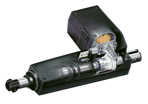
Актуатор беспечивает безопасное, плавное и точное передвижение и полный контроль над перемещением объекта. При этом он отличается низким энергопотреблением и имеет длительный срок службы, почти не нуждается в техническом обслуживании. Актуаторы Linak состоят из двигателя, редуктора и вала, включающего муфту.
Подъемная колонна может способствовать улучшению функциональности самых разнообразных рабочих зон: офисов, медицинских учреждений, сельскохозяйственных и промышленных предприятий, а также может использоваться при создании комфортабельной мебели. Подъемные колонны LINAK состоят из направляющих конструкций и интегрированных в них линейных приводов, обеспечивающих регулирование высоты подъема и опускания. Для обеспечения регулировки положения тяжелых предметов несколько таких колонн могут быть подключены параллельно. Подъемные колонны Linak отличаются компактным эргономичным дизайном.
Установка привода очень проста и, в отличии от гидравлических систем, позволяет существенно экономить пространство, поскольку не имеет насоса и шлангов. Система линейного перемещения должна вклчать в себя один или несколько таких актуаторов или колонн, блок управления и пульт управления для работы с приводами. Linak производит приводы мощностью от 200 до 12000 Н.
Компания LINAK, начиная с момента своего основания, стремится к достижению максимального качества своей продукции. Каждое изделие проходит тщательные испытания на соответствие самым строгим стандартам, и на всех стадиях сборки автоматических механизмов для подъема используются новейшие современные технологии и оборудование.
В настоящее время компания LINAK представлена в 31 стране земного шара. Официальным дистрибьютором актуаторов LINAK в России является FAM-Drive.
Принимаем оплату российскими картами, выкупаем и доставляем ваши заказы из магазинов США и Германии. Наша доставка работает в стандартном режиме.
×
Сейчас вы находитесь в городе Москва
Выберите город, в который Вы хотите осуществить доставку


![]()
![]()
Вопрос по товару?
Мы перезвоним!
Основные характеристики
Группа товаров:
Линейные приводы
Оригинальное название:
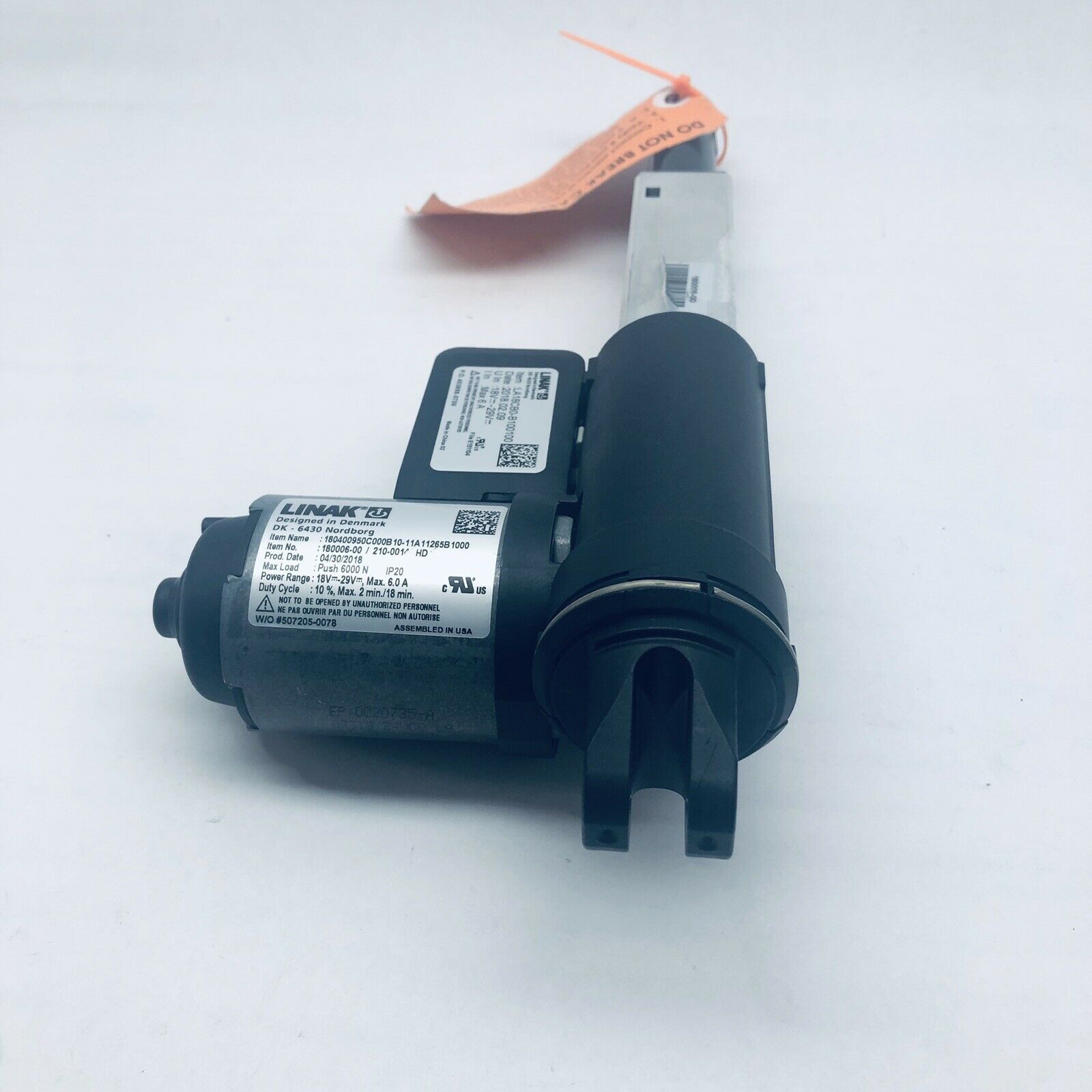
Linak DK 6430 Nordborg 230446-00 Actuator
Товар из США
Доставим в Ваш город
Артикул:266199686542
Продавец:
oneclickwarehouse
(43215)
Местонахождение:Ogden, Utah, US
Доставка до склада США
Бесплатно

Товары из магазинов
США и Европы
без наценок!
Отправили
67 000 посылок
с 2008 года!
Знаменитый
каталог eBay
на русском языке!
Доставка курьером
до двери
Почтой или в удобный пункт выдачи!
Похожие товары
Linak DK 6430 Nordborg 230446-00 Actuator
Linak DK 6430 Nordborg 230446-00 Actuator – можно купить на shopozz.ru с доставкой
из Ogden, Utah, US. Все товары из
категории «Линейные приводы» быстро и вовремя доставляются в Россию и страны СНГ.
Полную информацию о доставке можно посмотреть в разделе «Доставка».
На товары категории «Линейные приводы» действует доступная цена,
поэтому Linak DK 6430 Nordborg 230446-00 Actuator можно
приобрести всего за
27526 руб.
Не можете сделать выбор? Посмотрите другие товары продавца
oneclickwarehouse
(43215)
–
«Смотреть все товары».
Возникли вопросы о товаре, условиях оплаты либо доставки?
Закажи обратный
звонок!
Другие бренды категории
В чем наша ценность
Покупки без ограничений
- Доставка в любой город СНГ
- Простой процесс оплаты
- Каталог на русском языке
Доступ к 3 млн. товаров
- Доставка в любой город СНГ
- Простой процесс оплаты
- Каталог на русском языке
Консолидация и сервис
- Доставка в любой город СНГ
- Простой процесс оплаты
- Каталог на русском языке
Покупки в США и Европе — это просто
Вы делаете заказ — мы выкупаем товары и доставляем вам
Склад

$46
Косметика M.A.C.maccosmetics.com

$46
Часы Timexamazon.com

$15
Джинсы levi’sebay.com
К вам домойОтправляем в Россию и
во все страны СНГ
Начать выгодные покупки в зарубежных интернет-магазинах
- Manuals
- Brands
- Linak Manuals
- Control Systems
- CBH Advanced
- User manual
-
Contents
-
Table of Contents
-
Troubleshooting
-
Bookmarks
Quick Links
CBH Advanced systems
User manual
LINAK.COM/HOMELINE
Page 1 of 32
Related Manuals for Linak CBH Advanced
Summary of Contents for Linak CBH Advanced
-
Page 1
CBH Advanced systems User manual LINAK.COM/HOMELINE Page 1 of 32… -
Page 2: Table Of Contents
………………..10 ® Warranty……………………….10 Maintenance……………………..10 ETL-marking ………………………..11 Description of the HOMELINE CBH Advanced system …………..12 ® Mounting guideline for the CBH ………………..12 Cable relief ……………………..13 How to mount the locking device ………………..16 Disposal of LINAK’s products …………………..17 Main groups of disposal ……………………17 Disposal of batteries ……………………17…
-
Page 3: Preface
This User Manual does not address the end-user. It is intended as a source of information for the manufacturer of the equipment or system only, and it will tell you how to install, use and maintain your LINAK electronics. It is the responsibility of the manufacturer of the end-use product to provide a User Manual where relevant safety information from this manual is passed on to the end-user.
-
Page 4: Valid For
Valid for: This User Manual is valid for the following products: (See the first 3 — 5 characters on the label) Actuators: LA27, LA31 and LA40 Control box: CBH1220A and CBH1300A Power supply: SMPS001, SMPS002 or SMPS006 Controls: HB20, HC05 Wireless, HC10 Wireless, HC20 Wireless, HC30 Wireless Accessories: BA001, Lightplug001, LED Lightbox001, DC Connector001, USB Connector001, MD1000D2, LEDLightRail001, Bluetooth…
-
Page 5: Important Information
Only the power supply type SMPS001, SMPS002 or SMPS006, shall be used with the system (CBH Advanced System). The power supply shall not be covered while operating to allow sufficient cooling of this appliance.
-
Page 6: Safety Issues
Hall sensor and are not compatible with CBH Basic systems Please observe that if you use the SMPS001 or SMPS002 the CBH Advanced must be configured first as the CBH Advanced is standard set to 29V DC. This is done via the CBH configurator. BA001 will not be charged It is possible only to use 1 power supply (SMPS001, SMPS002 or SMPS006) for 2 CBH systems.
-
Page 7: Before Installation, Re-Installation Or Troubleshooting
• Make sure that the voltage of the control box/SMPS is correct before the system is connected to the mains. • System connection. The individual parts must be connected before the control box /SMPS is connected to the mains. See the User Manual for LINAK actuators, if necessary. During operation •…
-
Page 8: Only For Eu Markets
Only for EU markets This appliance can be used by children aged from 8 years and above and persons with reduced physical, sensory or mental capabilities or lack of experience and knowledge if they have given supervision or instruction concerning use of the appliance in a safe way and understand the hazards involved.
-
Page 9: Repairs
® DECLARATION OF INCORPORATION OF PARTLY COMPLETED MACHINERY LINAK A/S Smedevænget 8 DK — 6430 Nordborg Herewith declares that LINAK HOMELINE® products as characterized by the following models and types: Control Boxes CB7, CB9H, CBH Advanced, CBH Basic Linear Actuators…
-
Page 10: Misc. On The Homeline ® System
There is a 36 months’ warranty on the HOMELINE products CBH Advanced Systems against manufacturing faults from the production date of the individual products (see label). LINAK A/S’ warranty is only valid in so far as the equipment has been used and maintained correctly and has not been tampered with.
-
Page 11: Etl-Marking
ETL-marking Due to space limitations, the complete ETL-marking demands are not represented on the marking plates. The full ETL Recognized Component markings are shown here. C/N 120690 Conforms to UL962 Cert. to CSA Std. C22.2 No. 68-09 ETL Recognized Component mark for Canada and United States C/N 9901916 Conforms to UL962…
-
Page 12: Description Of The Homeline ® Cbh Advanced System
When the piston rod is at the innermost position, it must be possible to pull it out manually to its full travel length and to press it in again without much resistance and without using the motor. If this is not possible, contact your nearest LINAK dealer.
-
Page 13: Cable Relief
Cable relief: The CBH features a cable relief option. By using these small holes on the CBH, you can tie the DC cables from the SMPS unit to the control box by use of standard cable ties. It is recommended to use the cable relief especially if the control box is exposed to movement.
-
Page 14
CBH) Back/leg+neck/foot/hi-lo adjustment system A typical single actuator system for three adjustments consists of 1 x CBH Advanced (3 channels), 3 x LA27 / 31 / 40, 1 x SMPS and a hand control (A Bluetooth hand control requires a Bluetooth Adapter plugged into the CBH) ®… -
Page 15
How to pair the Bluetooth Adapter and the Bed Control App ® Plug the Bluetooth Adapter into a powered CBH. The pairing mode will last 3 minutes and is indicated with a blue flashing LED light that is visible through the transparent plastic. -
Page 16
Now the light will give a long blink and indicate that the hand control and the Bluetooth Adapter are paired up. ® Hand controls with SW0077075 ver. 1.04 or newer supports dual pairing: Pairing one hand control to two CBH Advanced using Bluetooth Adapters. ®… -
Page 17
How to connect the LED Light Rail to the CBH Simply connect the LED Light Rail to the CBH Advanced by using the RJ45 plug. CBH Advanced SMPS LED Light Rail Page 17 of 32… -
Page 18: How To Mount The Locking Device
How to mount the locking device (0705889) To ensure optimal cable relief on the SMPS001/002 a locking device (0705889) should be used. Follow the guide below on how to fix the locking device on the SMPS. 1. Take the SMPS 2.
-
Page 19: Disposal Of Linak’s Products
Disposal of LINAK’s products As LINAK’s customers often ask us how our products can be disposed of or scrapped we have prepared this guidance that enables a classification to different waste fractions for recycling or combustion. Guidance We recommend that our products be disassembled as much as possible and divided into different waste groups for recycling or combustion.
-
Page 20: Labels
Labels Label for HC20RF Label for HB22RF Label for LA27 Label for USB Connector Label for DC Connector Label for LED Light Rail Label for CBH Basic Label for LED Lightbox Label for Massage Motor Label for SMPS001 Label for SMPS002 Label for SMPS006 Page 20 of 32…
-
Page 21
DRAWING APPENDIX CBH Advanced Page 21 of 32… -
Page 22
SMPS001 SMPS002 Page 22 of 32… -
Page 23
SMPS006 Page 23 of 32… -
Page 24
LA27 Drawing no.:LA27001B LA31 HOMELINE Page 24 of 32… -
Page 25
LA40 HOMELINE HB20RF Hand Control Page 25 of 32… -
Page 26
HC05 Wireless HC10 Wireless Page 26 of 32… -
Page 27
HC20RF Hand Control Massage motor MD1 Page 27 of 32… -
Page 28: Addresses
HC30 Wireless HC32BL1000 HC33BL1000 HC34BL1000 Page 28 of 32…
-
Page 29
BA001 182.8 13.6 Bluetooth Adapter ® 255485 mm³ Iteration: 0 BA001-DRAW Page 29 of 32… -
Page 30
LED Light Rail Lightplug Page 30 of 32… -
Page 31
Iter.: accessory_lys.asm ACCESSORY_LYS Confidential: Property of LINAK A/S GROUP HEADQUARTER, DK-6430 NORDBORG, DENMARK Phone +45 73 15 15 15 ; FAX +45 74 45 80 48. Not to be handed over to, copied or used by third party. Material: Date:… -
Page 32
ACCESSORY_USB Confidential: Property of LINAK A/S GROUP HEADQUARTER, DK-6430 NORDBORG, DENMARK Phone +45 73 15 15 15 ; FAX +45 74 45 80 48. Not to be handed over to, copied or used by third party. LINAK APPLICATION POLICY The purpose of the application policy is to define areas of responsibilities in relation to applying a LINAK product defined as hardware, software, technical advice, etc. -
Page 33
While LINAK uses its best efforts to fulfil orders, LINAK cannot, for the same reasons as mentioned above, guarantee the availability of any particular product. Therefore, LINAK reserves the right to discontinue the sale of any product displayed on its website or listed in its catalogues or other written material drawn up by LINAK.
This manual is also suitable for:
Cbh1200b
Доставляем ушедшие из РФ бренды напрямую из США и Европы. Есть вопросы? Напишите нам в WhatsApp!
×
Сейчас вы находитесь в городе Москва
Выберите город, в который Вы хотите осуществить доставку
Доставка в
город Москва
: 24 октября
Основные характеристики
Товар из США
Доставим в Ваш город
Артикул:195679172427
Продавец:
olemanjohnson
(1157)
Местонахождение:Jasper, Georgia, US
Доставка до склада США
Бесплатно
Товары из магазинов
США и Европы
без наценок!
Отправили
67 000 посылок
с 2008 года!
Знаменитый
каталог eBay
на русском языке!
Доставка курьером
до двери
Почтой или в удобный пункт выдачи!
Похожие товары
Наши видеообзоры
Linak DK 6430 Nordborg 235067-00 ignition protection push 1800 N IPX6 12V 4.3A
Linak DK 6430 Nordborg 235067-00 ignition protection push 1800 N IPX6 12V 4.3A – можно купить на shopozz.ru с доставкой
из Jasper, Georgia, US. Все товары из
категории «Линейные приводы» быстро и вовремя доставляются в Россию и страны СНГ.
Полную информацию о доставке можно посмотреть в разделе «Доставка».
На товары категории «Линейные приводы» действует доступная цена,
поэтому Linak DK 6430 Nordborg 235067-00 ignition protection push 1800 N IPX6 12V 4.3A можно
приобрести всего за
24175 руб.
Не можете сделать выбор? Посмотрите другие товары продавца
olemanjohnson
(1157)
–
«Смотреть все товары».
Возникли вопросы о товаре, условиях оплаты либо доставки?
Закажи обратный
звонок!
Другие бренды категории
Покупки в США и Европе — это просто
Вы делаете заказ — мы выкупаем товары и доставляем вам
Склад
$46
Косметика M.A.C.maccosmetics.com
$46
Часы Timexamazon.com
$15
Джинсы levi’sebay.com
К вам домойОтправляем в Россию и
во все страны СНГ
Начать выгодные покупки в зарубежных интернет-магазинах
Компания Linak предлагает решения на основе электрических линейных приводов, которые обеспечивают плавность движения различного оборудования. Изделия находят применение в различных отраслях, начиная от сельского хозяйства и средств промышленной автоматизации до медицинского оборудования, мебели повышенной комфортности и предметов интерьера. Продукция создается профессионалами с использованием инноваций и имеет высокое качество, что делает ее востребованной по всему миру. Линейные приводы этого бренда имеют длительный срок действия и продолжают работать, когда другие выходят из строя.
.jpg)
Линейные приводы Linak
Линейные приводы преобразуют вращательное движение двигателя в действие толкающего или тянущего типа. Linak DK 6430 Nordborg купить стоит для тех ситуаций, когда требуется простое, безопасное и плавное передвижение с точным и удобным управлением. Для таких ситуаций данный привод – идеальное решение. Он также отлично подходит для областей применения, где требуется наклон, подъем, натяжение и толкание. Привод DK 6430 Linak идеально подходит для применения в условия, требующих коротких линейных перемещений. Устройство зарекомендовало себя прочным и надежным, которое отлично выполняет свои функции практически в любых ситуациях.
Компания выпускает линейные приводы:
- Актуаторы — устройства, которым требуется вход источника энергии, вход внешнего сигнала, оба из которых затем создают выход, обычно в форме движения, которое может быть либо вращательным, либо линейным.
- Подъемные колонны — обеспечивают более длинный ход, поскольку имеют несколько ступеней, что позволяет им растягиваться и сокращаться на большую длину, чем в полностью закрытом состоянии.
- Пульты – устройства, которые регулируют воздействие блока на актуатор и обеспечивают движение.
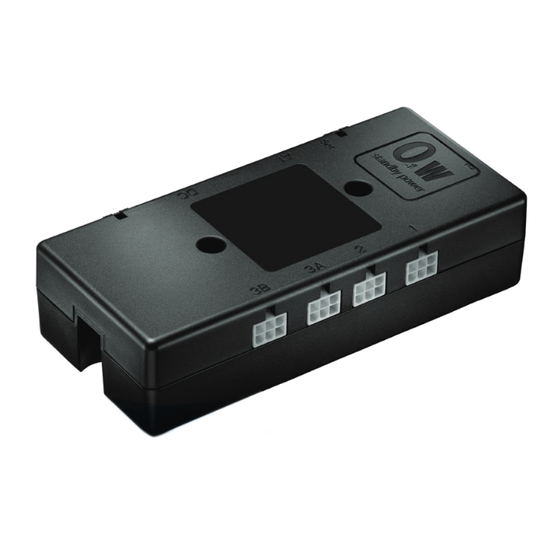
- Блоки управления – большое семейство интеллектуальных блоков, позволяющих производить регулировку при различных применениях актуаторов.
Достоинства линейных приводов Linak
Linak DK 6430 — чрезвычайно выносливый, удобный в интеграции и простой в установке привод, который расширяет функциональность оборудования и придает ему особую стойкость.
.jpg)
Линейные приводы этого бренда имеют следующие преимущества:
- Готовы к установке системы в комплекте с различными двигателями и блоками управления;
- имеют широкий ассортимент конфигурируемых решений практически под любые нужды;
- выпускают все основные типы приводов, имеющиеся на рынке;
- являются универсальными многокоординатными системами на основе линейных модулей;
- обладают высокой эффективностью и надежностью;
- имеют доступный по всему миру сервис от местных представительств.
Актуаторные системы и блоки управления обеспечивают предоставление преимуществ в больницах и офисах, системах сточных вод и оборудования, применяемого в экстремальных условиях, в сельскохозяйственном и строительном секторе.
Компания Linak занимается разработкой и выпуском полных систем актуаторов, обеспечивающих плавное и точное перемещение. Они используются в различных областях. Решения бренда на основе электрических линейных приводов создают оптимальные условия работы, а также плавное движение оборудования различного назначения. Продукция производителя используется повсеместно — от сельскохозяйственного сектора до автоматизации производственных процессов. Международный лидер использует инновационные технологии в процессе создания актуаторов.

Особенности продукции
Линейные приводы бренда обеспечивают перемещение по прямой, заданной кривой или в пространстве. Это удобно самостоятельное устройство с системой управления. Приводы linak dk 6430 обеспечивают легкое и бесшумное перемещение. Продукцию бренда можно условно разделить на 4 стратегических направления по сферам использования. Такая классификация обеспечивает соответствие продукции разнообразным сферам и улучшение ее эксплуатационных характеристик для использования в том или ином сегменте.
- TECHLINE — решения и системы для промышленной автоматизации, а также для использования в энергетике, сельском хозяйстве;
- DESKLINE — решения, предназначенные для офиса, рабочего места, магазинов, ТРЦ;
- HOMELINE — продукции для мебели;
- MEDLINE и CARELINE — медицинское оборудование и для отрасли здравоохранения.
Отличительной чертой решений компании является их гибкость. Благодаря этому удается удовлетворить требования клиентов. Кроме того, компания предлагает большой ассортимент комплектующих стороннего производства, которые полностью совместимы с актуаторами. Эффективность современной техники зависит от скорости ее реакции на сигналы, данные и компоненты. Приводы со встроенным контроллером легко адаптируются в работу любой системы благодаря поддержке основных протоколов.
Ассортимент
Принцип работы приводов заключается в преобразовании одного вида движения — вращательного в другой вид — поступательное. С его помощью удается поднимать, настраивать, наклонять или перемещать элементы конструкции всего с помощью одного нажатия клавиши. Колонны и привод dk 6430 linakотличаются почти самой расширенной область применения. Еще один продукт бренда — актуаторы. Они создают безопасное, плавное передвижение объекта, а также обеспечивают контроль над этим процессом. Конструкция устройства состоит из двигателя, редуктора, вала и муфты. Подъемные колонны, которые предлагает Linak способствуют лучшей функциональности отдельных зон, например, в офисе, на рабочем месте. Они отличаются компактными габаритами, простой установкой. Основные элементы колонны это направляющие и встроенный линейный привод. Основное их назначение — выполнение опускания и регулировка высоты.
Linak dk 6430 nordborg купить можно на нашем сайте. Компания А-К-С занимается прямыми поставками промышленного оборудования и запасных деталей в Россию. Мы сотрудничаем с разными брендами из США, Азии, Европы. С условиями поставки ,сроками, актуальными ценами можно ознакомиться на сайте в соответствующих разделах.
Не нашли, что искали?
Отправьте заявку: запросим наличие и цены у партнеров или дилеров