В данном документе собраны все инструкции по блокам управления автоматикой ворот CAME. Здесь представлены инструкции только для плат и блоков управления автоматикой ворот для удобства поиска нужных документов. Для просмотры других инструкций по автоматике ворот смотрите похожие статьи.
Похожие статьи

Инструкции автоматика CAME
В данном документе собраны все инструкции по автоматике ворот CAME, а также по всему дополнительному оборудованию. Инструкции на приводы откатных, распашных и гаражных ворот, системы безопасности (фот..

Инструкции приводы распашных ворот CAME
В данном документе собраны все инструкции по приводам распашных ворот CAME. Здесь представлены инструкции только на приводы распашных ворот для удобства поиска нужных документов. Для просмо..

Инструкции приводы откатных ворот CAME
В данном документе собраны все инструкции по приводам откатных ворот CAME. Здесь представлены инструкции только на приводы откатных ворот для удобства поиска нужных документов. Для просмотры других ин..

Инструкции приводы гаражных ворот CAME
В данном документе собраны все инструкции по приводам секционных гаражных ворот CAME. Здесь представлены инструкции только на приводы гаражных ворот для удобства поиска нужных документов. Для просмотр..

Инструкции приводы промышленных ворот CAME
В данном документе собраны все инструкции по приводам промышленных секционных ворот CAME. Здесь представлены инструкции только на приводы промышленных ворот для удобства поиска нужных документов. Для ..
Подбор подходящего шлагбаума – это непростой процесс, ведь здесь важно учесть определенные нюансы, чтобы не ошибиться с выбором. Специалисты CAME всегда придерживаются одной стратегии, которая помогает им подбирать наилучшее оборудование для объектов любой сложности.
Для начала нужно определить, какую ширину проезда на вашем объекте требуется перекрыть.
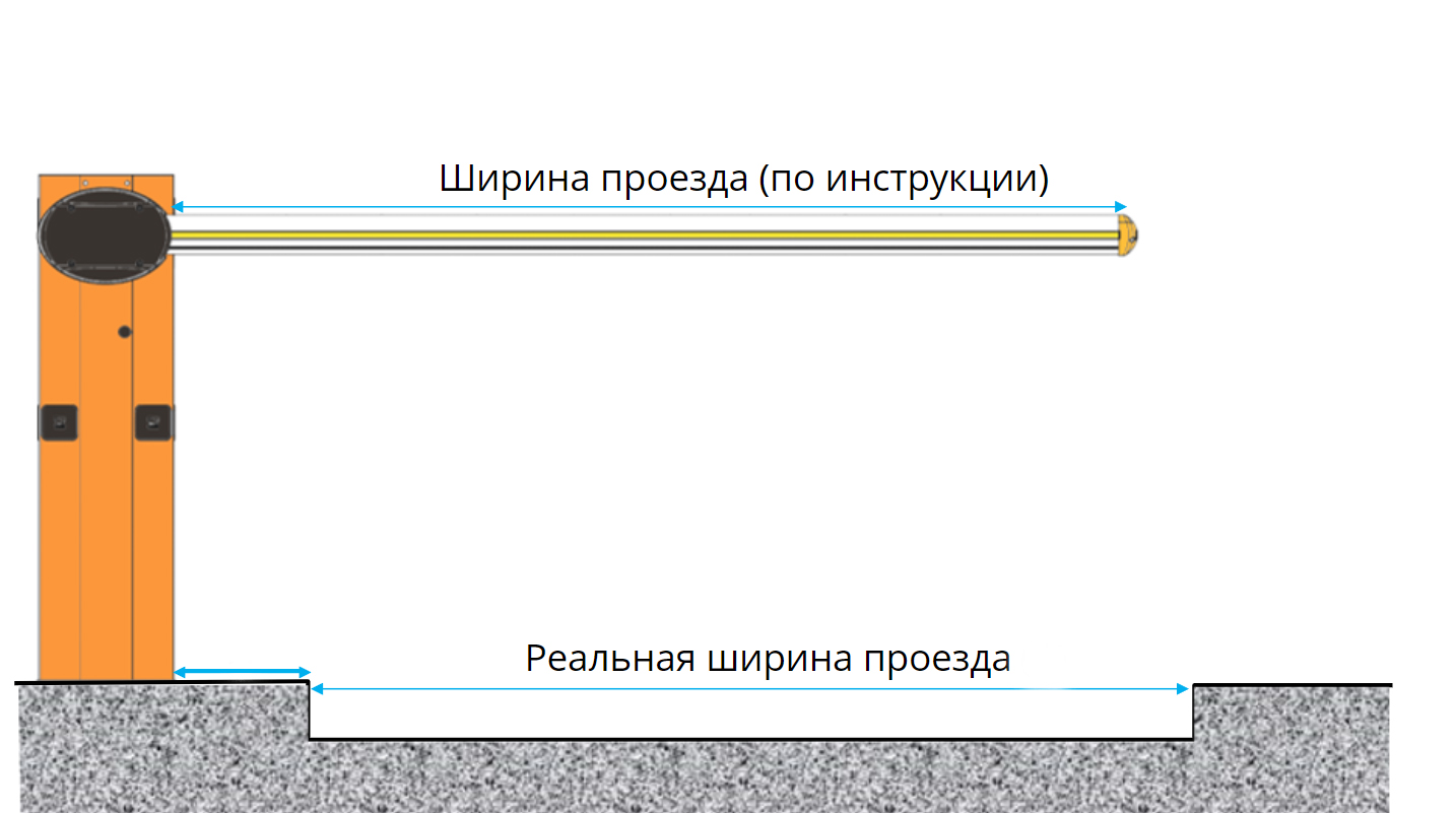
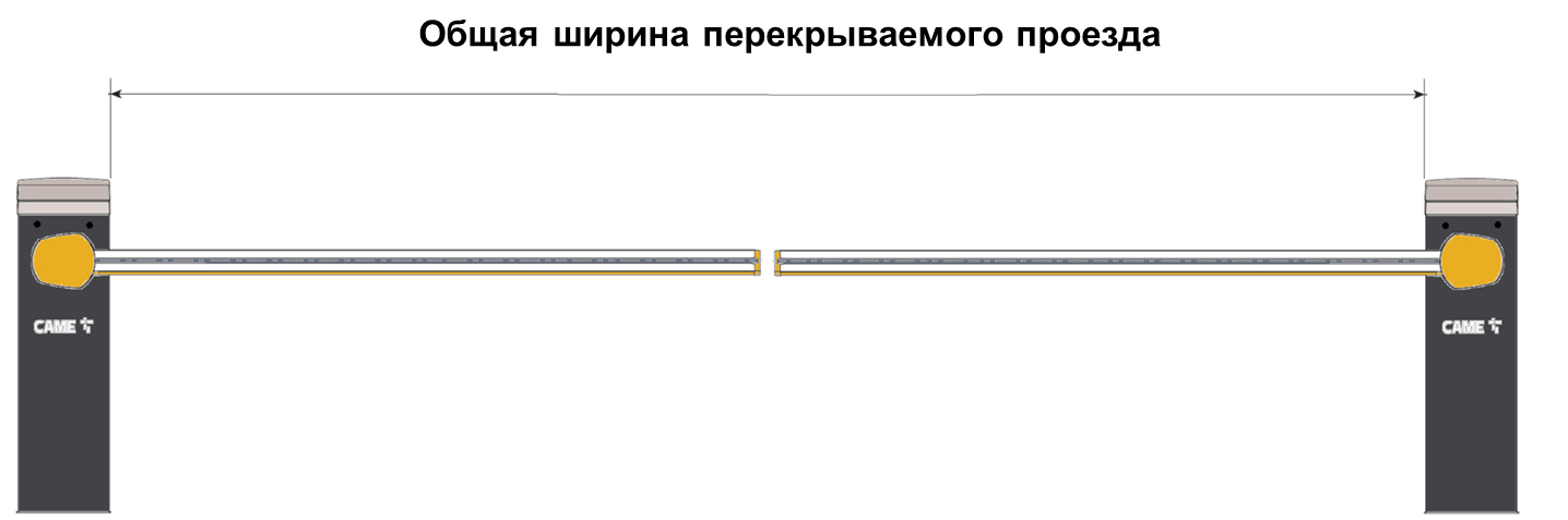
Следует обратить внимание, что сама тумба будет располагаться на некотором расстоянии от проезжей части и, в зависимости от длины стрелы, может потребоваться установка фиксированной опоры, которая также не должна располагаться на проезжей части. Таким образом, реальная длина стрелы будет превышать ширину проезжей части. Если необходимо перекрыть большой проезд, например, 7 метров и более, можно установить не один шлагбаум, а два, расположив их с обеих сторон проезда, и настроить для работы в синхронном режиме. Это особенно актуально в случае, когда необходимо обеспечить высокую скорость открытия и закрытия, так как чем короче стрела, тем выше можно будет настроить скорость.
Затем следует определить, какие аксессуары необходимы для вашего шлагбаума. Это могут быть:
- светоотражающие наклейки,
- подсветка стрелы и тумбы,
- система аварийного питания,
- фиксированная или подвижная опора для стрелы,
- шарнир для складывания стрелы (актуально, если на вашем объекте есть ограничения по высоте),
- противоударный резиновый профиль и т. д.
Именно от необходимых аксессуаров и зависит выбор тумбы шлагбаума и типа стрелы. Подробнее о том, какие аксессуары представлены в ассортименте CAME, вы можете узнать в обзоре аксессуаров для шлагбаумов.
9 марта 2023 г.
-
Contents
-
Table of Contents
-
Bookmarks
Quick Links
OVERHEAD GARAGE DOORS
VER
SERIES
INSTALLATION MANUAL
V900E
Related Manuals for CAME V900E
Summary of Contents for CAME V900E
-
Page 1
AUTOMATION FOR SECTIONAL AND OVERHEAD GARAGE DOORS SERIES INSTALLATION MANUAL V900E… -
Page 2
2.1 Intended use The V900E automated kit is designed to power sectional and overhead doors installed in condominiums and residential homes. The use of this product for purposes other than as described above and installation executed in a manner other than as instructed in this technical manual are prohibited. -
Page 3
2) 001V0670 – Emergency battery start-up card, houses 2 (12V-1,2Ah not included) batteries ; Important! Check that the safety equipment and accessories are CAME originals; this is a guarantee that also makes the system easy to set up and upkeep. -
Page 4
4.4 Dimensions 5 Installation The installation must be carried out by export, qualified personnel in total compliance with the norms in effect. 5.1 Preliminary checks Before proceeding with the installation, it is necessary to: • Make sure the area selected for the mounting of the base and for the unit itself is hazard free; •… -
Page 5
5.3 Cable list and minimum thickness Connections Type of cable Length of cable 1 < 10 m L. of cable 10 < 20 m L. of cable 20 < 30 m 230V power supply 3G x 1,5 mm 3G x 2,5 mm 3G x 4 mm Flashing lamp 2 x 0,5 mm… -
Page 6
5.5 Preparing the transmission guide The following applications are only examples, as the space required for unit installation and the accessories vary depending on dimensions and therefore it is up to the installer to select the best solution. 1) Fasten the bracket to the tension device on the transmission guide using the supplied bolts and washers. M6 x 20 2) Position the transmission guide in the following manner: — for sectional doors directly above spring-release coiling shaft (between 20 and 30 mm of the shaft’s axis). -
Page 7
5.6 Fastening the transmission guide 1) Fasten the transmission guide to the centre of the doorway using the proper screws. Raise the guide until it is horizontal with the ceiling so as to choose the proper type of fastener. 2) If the angle brackets are not suffi cient, cut the tension brackets down to the right length and fasten them to the ceiling. N.B.: to strengthen the bar additional angle or tension brackets may be installed. -
Page 8
5.7 Fastening the guide arm to the transmission guide 1) Fasten the guide arm to the top of the door frame, perpendicularly to the transmission guide. Use the supplied rivets and other suitable bolts and screws. 2) Release the traction slide by turning the small level clockwise. Move the slide towards the door and hook it onto the guide arm with the supplied bolt. -
Page 9
5.8 Fastening the gearmotor to the transmission guide 1) Remove the cover of the motor unit. UNI 6954 ø 3.9 x 13 2) Fasten the motor unit to guide’s support racket using the three screws supplied with the kit. N.B.: if needed, the unit may be fasten in the other three perpendicular positions, as per the drawings. UNI 6955 ø… -
Page 10
6 Electronic control panel 6.1 General description The control panel is powered by 230V on the L-N terminals, with a 50/60 Hz frequency. The command devices and accessories run on 24V. Moreover, the total accessories cannot run on more than 40W. The panel controls a service light to light up the service area;… -
Page 11
6.2 Main components 1) Line fuse 1.6A 2) Emergency batteries’ slot 3) Gearmotor 4) Transformer 5) Transformer connection terminal board 6) Motor fuse 7.5A 7) Gearmotor connection terminal board Encoder connection terminal board 9) Signal Led for radio-code and encoder programming 10) Radio-code save button 11) SLOW.
 -
Page 12
Gearmotor, encoder and transformer (only for possibile maintenance) Gearmotor Transformer 24V d.c. with encoder Command and safety devices If a button is connected, then remove the fuse-bridge. Stop button (N.C. contact) — Stops movement, excludes the automatic closing functions. To restart the automated kit, press a command button or a remote control button. Key and/or push button selector switch (N.O. -
Page 13
Warning devices Movement Flasher (contact capacity: 24V – 25W max.) Flashes during the opening and closing phases. 6.4 Function selection 1 ON – Encoder programming — activates the opening and closing end-stops adjustment procedure. deactivated. Keep the dip-switch in OFF position 6.5 Adjustments Trimmer SLOW.SENS. -
Page 14: Programming The End-Stops
7 Programming the end-stops IMPORTANT: before performing any programming, read the instructions carefully. Carry out the following instructions in the proper order otherwise the programming will fail. Preliminary operations — Release the automation and position the door in the fully opened position. — When the door is fully opened, fasten the mechanical stop to the traction slide.
-
Page 15
…then briefly press the ENC/RADIO button (if the signal led stays on for some seconds and then starts flashing again, the programming operation is satisfactorily complete). Programming the end-stop in the opening phase — Push and keep pressed the OPEN button until the door is fully open..then briefly press the ENC/RADIO button (if the signal led stay on the programming operations is satisfactorily complete). -
Page 16
8 Activating the remote control Antenna Connect the antenna with the RG58 cable to the apposite terminals on the board. Radiofrequecy card Only for highlighted cards. Position the jumper as show in the illustration depending on the series of transmitters used (see figure). Radiofrequency Series of Frequency/MHz… -
Page 17
Transmitters TOP SERIES T432M — T312M Input the code into the C selector and set the channel on D (P1 = CH1 and P2 = CH2: default setting) T432S — T432SA — T434MA — T432NA — T434NA T434M — T314M Input only the code See instructions attached P1 = CH1… -
Page 18
QUARZ TOP SERIES Common coding operations for transmitters: 1 note down the selected code (for future need) 2 insert the J coding jumper to activate the procedure 3 memorise the code, pressing P1 and/or P2 in the above sequence. At the end, a double sound will confirm the memorisation. 4 remove the J jumper T262M — T302M The fi… -
Page 19
T2622M — T3022M T264M — T304M 1° Code P1 = CH1 P1 = CH1 P2 = CH2 P2 = CH2 P3 = CH3 P4 = CH4 2° Code P3 = CH1 P4 = CH2 Memorisation 1) Keep the ENC/RADIO pressed on the circuit board. The led indicator will fl ash. ENC/RADIO LED flash 2) press the transmitter button to be memorised. -
Page 20
UNI EN ISO 14001 standard to ensure environmental protection. Please continue our efforts to protect the environment—which CAME considers one of the cardinal elements in the development of its operational and market strategies—simply by observing brief recommendations as regards disposal: DISPOSAL OF PACKAGING –… -
Page 21
Declares under its own responsibility that the equipments for automatic garage doors and gates listed below: AUTOMATION DRAW SYSTEM FOR V900E OVERHEAD AND SECTIONAL DOORS CONTAINING SOME OF THE FOLLOWING ACCESSORIES V201 — V121 — V122 — V0670 — V0679 — V0682 — V0683 — V0684… -
Page 22
CAME UNITED KINGDOM LTD UNIT 3, ORCHARD BUSINESS PARK TOWN STREET, SANDIACRE NOTTINGHAM — NG10 5BP — U.K. Tel 0044 115 9210430 Fax 0044 115 9210431…
 Encoder connection terminal board 9) Signal Led for radio-code and encoder programming 10) Radio-code save button 11) SLOW.