-
Contents
-
Table of Contents
-
Troubleshooting
-
Bookmarks
Quick Links
instructions
1SDH000460R0002
L2778
Installation, service and
for low voltage air circuit-breakers
Emax
Related Manuals for ABB SACE Emax Series
Summary of Contents for ABB SACE Emax Series
-
Page 1
Installation and service Installation, service and instructions maintenance instructions for low voltage air circuit-breakers Emax 1SDH000460R0002 L2778… -
Page 2: Table Of Contents
12.8 Accessories …………..« 41 8.3.4 Operating mechanism maintenance ……« 22 12.8.1 ABB SACE PR010/T test and configuration unit ..« 41 12.8.2 BT030 communication unit ……….« 41 Measures to be taken for any operating 12.8.3 PR021/K and HMI030 units ……….. « 41 anomalies …………
-
Page 3: Table Of Contents
13.8 Accessories …………… « 75 for the PR122/P …………« 49 13.8.1 ABB SACE PR010/T test and configuration unit ..« 75 13.2.9.12.1 Summary of the additional protection functions 13.8.2 BT030/B communication unit ……..« 75 for the PR122/P with the optional PR120/V module . « 50 13.8.3…
-
Page 4: Table Of Contents
14.8 Accessories …………… « 112 14.2.9.15 Summary table of the protection function settings 14.8.1 ABB SACE PR010/T test and configuration unit ..« 112 for the PR123/P …………« 86 14.8.2 BT030 communication unit ……..« 112 14.2.9.16 Table of measurements ……….« 87 14.8.3…
-
Page 5: Table Of Contents
15.3 PR120/K — SIGNALLING module ……. page 121 15.3.1 General characteristics ……….« 121 15.3.2 Front view …………..« 121 15.3.3 Releases complete with the module ……« 121 15.3.4 Characteristics of the digital input ……« 121 15.3.5 Characteristics of the signalling contacts ….« 121 15.3.6 Power supply …………
-
Page 6
L2234 Model Scale Apparatus Emax L2778 Page No. Doc. No. 1SDH000460R0002 5/158… -
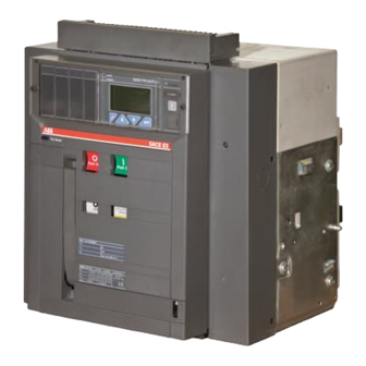
Page 7: Description
General characteristics The SACE Emax series of circuit-breakers and disconnectors consists of a steel sheet structure which houses the operating mechanism, the poles and the auxiliary parts. Each pole, insulated from the others, contains the circuit-breaking parts and the current transformer of the corresponding phase.
-
Page 8: Fixed Part Construction Characteristics
Fixed part construction characteristics 1 Steel sheet supporting structure 2 Earthing contacts (a: for all versions; b: for E4, 3 Safety shutters (IP20 degree of protection) 4 Insulating terminal support base 5 Terminals 6 Contacts for signalling connected/test isolated/disconnected (on request) 7 Sliding contacts 8 Padlock for safety shutters (on request)) 9 Anti-racking-in lock for circuit-breakers of…
-
Page 9: Installation
With regard to lifting, follow the instructions: the circuit-breakers must be placed on a sturdy supporting surface and lifted, preferably, by means of a special fork-lift truck. However, the use of ropes is allowed. In this case, the lifting ropes must be hooked up as shown in the figures (the lifting plates are always supplied with the circuit-breaker).
-
Page 10: Installation Of The Fixed Part
Installation of the fixed part (Fig. 12) Attach the fixed part by means of the screws (1), washers (2) and nuts (3) (M8 x 16), supplied by ABB SACE. if other screws are used, make sure that the head of the screws does not extend more than 5.5 mm from the base of the fixed part.
-
Page 11: Installation Of The Flange On The Compartment Door
Installation of the flange on the compartment door (Fig. 13) – Make the compartment door drillings specified in the «Overall dimensions» paragraph. — Attach the flange (1) on the front of the compartment door, fixing it from the inside by means of the self-tapping screws (2). Notes (*) For the E1-E2-E3 fixed parts, there are four fixing points, whereas…
-
Page 12: Examples Of Positioning The Connection Busbars According To The Types Of Terminals
5.1.2 Examples of positioning the connection busbars according to the types of terminals The connection busbars enable the connection between the terminals of the circuit-breakers and the busbars of the switchgear. Their sizing must be carefully studied by the switchgear designer. Some examples of possible constructions in relation to the shape and size of the circuit-breaker terminals are given in this paragraph.
-
Page 13: Assembly Procedure For The Connection Busbars
5.1.3 Assembly procedure for the connection busbars Check the state of the contact surfaces of the connections very carefully: they must be very clean with no burrs, dents or traces of rust which must be eliminated using a fine file or an emery cloth to prevent localized increases in temperature. On completion of the operation, remove all traces of grease or dust with a cloth soaked in a suitable solvent.
-
Page 14: Withdrawable Circuit-Breaker
5.3.2 Withdrawable circuit-breaker For connection of the moving part to the auxiliary circuits, a connection with sliding contacts is available on the fixed part (see figure), identified by code X on the electrical circuit diagram. The terminals of the fixed connector are immediately accessible when the compartment door is open. Furthermore a terminal box identified by code XF is available for connecting the position contacts of the moving part in relation to the fixed part.
-
Page 15: From Normally Closed (Opening) To Normally Open Closing) Or Vice Versa
Conversion of the auxiliary contacts or of the signalling contacts (disconnected — test isolated — connected), from normally closed (opening) to normally open (closing) or vice versa The contacts are wired at the factory as shown on the electrical circuit diagram. If it is necessary to change their state for installation requirements, proceed as follows.
-
Page 16: Putting Into Service
Putting into service General procedures – Check tightness of the power connections at the circuit-breaker terminals – Carry out all the preparatory operations on the release – Make sure that the value of the auxiliary circuit power supply voltage is between 85 and 110% of the rated voltage of the electrical applications –…
-
Page 17: Instructions For Use
Instructions for use Operating and signalling parts 1 Pushbutton for the manual opening operation 2 Lever for manual loading of the closing springs 3 Mechanical indicator for circuit-breaker open “O” and closed “I” 4 Mechanical indicator for protection release tripped (on request) 5 Pushbutton for the manual closing operation 6 Signalling device for springs loaded — unloaded 7 Operation counter (on request)
-
Page 18: Circuit-Breaker Closing And Opening Procedures
Circuit-breaker closing and opening procedures The operation of the circuit-breaker can be either manual or electrical. a) Manual loading of the closing springs – Make sure that the indicator (3) shows «O» (circuit-breaker open) – Make sure that the indicator (6) is WHITE (springs unloaded) –…
-
Page 19: Racking-In/Out Operation
Racking-in/out operation WARNING A) Open the circuit-breaker before carrying out any racking-in/out operation. B) The circuit-breaker (moving part) and fixed part are fitted with a lock which prevents the fixed part from being racked into the circuit-breakers with a different rated current: the congruence of the anti-racking-in lock must be checked by the operator before carrying out the racking- in operation to avoid any unnecessary stress.
-
Page 20: Maintenance
b) Passing from the DISCONNECTED to the TEST ISOLATED position Make sure that the indicator (9) is in the DISCONNECTED position. For the connection procedure, make sure that the key (12) is in the correct position and/or the padlock (14), if any, has been removed. Make sure that the circuit-breaker is open.
-
Page 21: Maintenance Program
With regular maintenance, SACE Emax circuit-breakers, either with or without a geared motor, can withstand the following operation without replacement of parts. Rated uninterrupted current Mechanical life (*) Electrical life Iu (40 °C) No. of operations Frequency 440 V ~ 690 V ~ Frequency x 1000…
-
Page 22: General Inspection Of The Circuit-Breaker
– Deformation or cracks of the insulating parts nuts appropriately – Insulating contacts oxidized (only for withdrawable – Ask ABB SACE to replace the damaged parts circuit-breaker) – Remove the shutters and clean with a rough cloth – Wear or overheating marks or screws loose on the…
-
Page 23: Operating Mechanism Maintenance
Fig. 33a Fig. 33b Fig. 33c 8.3.4 Operating mechanism maintenance – Carry out the checks and take the action listed under item 1 of the table in paragraph 8.3.2. – Lubricate the bearings of the drive shaft with MU-EP1 (AGIP) grease, including those on the sides of the circuit-breaker. Equivalent greases: ESSO Beacon EP1 — BP LTX1 — SHELL AVANIA GREASE R1 — KLUBER LUBRIFICATION CENTO PLEX 2P –…
-
Page 24: Measures To Be Taken For Any Operating Anomalies
Replace the coils • • • Operating mechanism blocked Operate by hand. If the fault persists contact ABB SACE • Key not inserted in the opening mechanism lock Insert and turn the key • Circuit-breaker in intermediate position between connected…
-
Page 25: Accessories
10. Accessories 10.1 Electrical accessories Shunt opening/closing (YO/YC) and second shunt opening release (Y02) This allows remote opening or closing control of the apparatus. Given the characteristics of the circuit-breaker operating mechanism, opening (with the circuit-breaker closed) is always possible, whereas closing is only possible when the closing springs are loaded. Most of the releases can operate with either direct or alternating current.
-
Page 26
Time delay device for undervoltage release (D) The undervoltage release can be combined with an electronic time-delay device for installing outside the circuit-breaker, which enables a delay in the tripping of the release with preset, adjustable times. The use of the delayed undervoltage release is recommended when the power supply network of the release can be subject to power cuts or short-lived voltage drops, in order to avoid trips. -
Page 27
Mechanical and electrical trip signalling for overcurrent releases The following signals are available following tripping of the overcurrent release: a) Mechanical trip signalling for overcurrent releases This enables a visual signalling on the operating mechanism by pushing the trip pushbutton in when the circuit-breaker has been opened following tripping of an overcurrent release. -
Page 28: Mechanical Locks
b ) Homopolar toroid for the power supply earthing conductor (star center of the transformer) PR122 and PR123 microprocessor-based electronic releases may be used in combination with an external toroid located on the conductor, which connects the star center of the MV/LV transformer (homopolar transformer) to earth: in this case, the earth protection is defined as Source Ground Return.
-
Page 29: Spare Parts And Retrofitting
For the change over, the customer can use a suitable electronic relay, whose diagram is supplied by ABB SACE. The mechanical interlocks between two or three circuit-breakers are made by means of cables that can be used for circuit-breakers installed, either side-by-side or one over the other.
-
Page 30: Protection Releases — General Notes
11. Protection releases — General notes Emax, the range of ABB air circuit-breakers, now has a new range of electronic relays. These are called PR121, PR122 and PR123, and they substitute the previous range PR111, PR112 and PR113. The new protection releases integrate all the functions of their predecessors, adding new and interesting technical features that are useful for satisfying every current and future system installation need.
-
Page 31: Safety Notes
Voltage Sensor (see also VT) 11.2.2 Notes A. Use the “Belden 3105A”- type two-wire cable for instance (not supplied by ABB SACE). B. Use the “Belden 3106A”- type three-wire cable for instance (not supplied by ABB SACE). C. The unit has a “backup-protection” function; if the first command to the opening solenoid does not open immediately the circuit-breaker (TC partially fault), TRIP commands are repeatedly sent until the circuit-breaker opens (providing a Vaux is present) or the current disappears (if self-power supplied).
-
Page 32: Sace Pr121/P Release — Identification
12.2.1 General The PR121/P unit is a high-performance self-supplied protection unit with Protection functions for the ABB SACE ‘Emax’ range of 3-pole and 4- pole low voltage air circuit-breakers. The unit’s user interface also enables parameter setup and complete pre-alarm and alarm management with LED warning/alarm indicators for the protection and watchdog functions.
-
Page 33: Environmental Characteristics
The presence of the auxiliary power supply enables the relay unit to be used even with the circuit-breaker open. The characteristics of the power pack are given in the table below. Characteristics Version PR121/P Auxiliary voltage (galvanically separated) 24V DC ±20% Maximum ripple Inrush current @ 24V ~10A for 5 ms…
-
Page 34: Description Of The Protection Functions
1 2 . 2 . 6 Description of the protection functions 12.2.6.1 Protection “L” The «L» is the only protection that cannot be disabled because it is for self-protection against overloading of the relay itself. The type of curve that can be set is t=k/I The inverse-time protection trip time is given by the expression where l <…
-
Page 35: Summary Table Of Protections
12.2.7 Summary table of protections Trip Trip Protection Trip threshold Trip time time threshold tolerance tolerance I1 = 0.4 — 0.425 — 0.45 — 0.475 — 0.5 — Release between (t=k/I 0.525 — 0.55 — 0.575 — 0.6 — 0.625 — t1 = 3 — 12 — 24 — 36 — 48 — 72 1.05 and 1.2 x I1 ±…
-
Page 36: Trip Curves
12.2.9 Trip curves The trip curves provided are merely for guidance and only show a sub-group of the possible selections (see par. 12.2.7). 12.2.9.1 Trip curves for functions L-I 0.4 … 1 1.5 … 15 12.2.9.2 Trip curves for functions L-S(t =k/I 0.4 …
-
Page 37: Trip Curves For Functions L-S(T=K)-I
12.2.9.3 Trip curves for functions L-S(t=k)-I 0.4 … 1 1.5 … 15 0.1 … 0.8 t = k 12.2.9.4 Trip curves for function G 0.2 … 1 0.1 … 0.8 t = k L2234 Model Scale Apparatus Emax L2778 Page No. Doc.
-
Page 38: Other Functions
12.3 Other functions 12.3.1 Indication of the cause of the trip and trip test button Using the «i Test» button, you can retrieve the information stored in the past 48 hours. You can also perform a trip test by pressing and holding the button for 7 seconds and an Autotest by pressing and holding the button for 3 seconds, again with the PR030/B battery unit connected and no current flowing through.
-
Page 39: Trip Test
(see Watchdog). To be able to do the test, you need to connect the PR030/B battery unit. 12.5.2 Initial settings ABB SACE will see to applying the adhesive labels on the PR121/P for all the variables relating to the circuit-breaker (e.g. Type of circuit-breaker, Rating Plug size, etc.).
-
Page 40: Pr121/P Default Settings
1 2 . 5 . 4 PR121/P default settings The PR121/P is supplied by ABB SACE with the following preset parameters: Protection Thresholds Time 1 In 144 s 0.1 s 4 In 0.1 s Mains frequency 50 Hz Neutral sel.
-
Page 41: Definition Of The Alarms And Signals For The Pr121/P Unit
12.7 Definition of the alarms and signals for the PR121/P unit 12.7.1 Optical signals The following table shows how the LEDs are managed in accordance with the IEC standard 60073 (and clause 4.2.3.2 in particular). The LED alerts you to the status of the function set on its zone; e.g. in the figure in par. 12.5 the LED referenced as 1 identifies the status of the function L.
-
Page 42: Troubleshooting
Using the BT030 wireless communication unit, the PR121/P can be connected by radio to a hand-held PC (PDA) or normal PC, thus extending the amount of information available to the user. In fact, using the SD-Pocket communication software by ABB SACE, you can read the values of the currents flowing through the circuit-breaker, the value of the last 20 currents broken and the protection settings.
-
Page 43: Sace Pr122/P Release — Identification
The PR122/P is a high-performance self-supplied protection unit with Protection, Measurement, Data storage, Communication (optional), Self-test, Load control and Zone selectivity functions for the ABB SACE ‘Emax’ range of 3- and 4-pole low-voltage air circuit-breakers. The unit’s user interface also enables parameter setup and complete the prealarm and alarm management for the protection and watchdog functions.
-
Page 44: Electrical Characteristics
With the optional PR120/V module, the PR122/P also assures the following protections: Symbol Protection against undervoltage overvoltage residual voltage reverse active power underfrequency overfrequency phase-to-phase voltage unbalance (as an alternative to phase currents) 13.2.2 Electrical characteristics Rated operating frequency 50/60 Hz ±10% Pass band 3000 Hz max Peak factor…
-
Page 45: Calculating The Rms
Protection against instantaneous short-circuit“I”; Protection against closing on short-circuit “MCR”; Protection against earth fault with adjustable delay “G”; Protection against instantaneous short-circuit at high currents «Iinst»; Protection against phase unbalance “U”; Protection against overtemperature “OT”. The PR122/P unit allows current signal processing of the neutral pole with different relationships relative to the value of the phases. N.B.: Beyond 15.5xIn of current on the Ne, the protection is considered as being set to 100%.
-
Page 46
1 3 . 2 . 9 Description of the protection functions 13.2.9.1 Protection “L” The «L» is the only protection that cannot be disabled because it is for self-protection against overloading of the relay itself. The types of trip curves settable are divided into two groups according to the standard they refer to. -
Page 47: Zone Selectivity «S
13.2.9.2.3 Zone selectivity “S” The zone selectivity function, guaranteed only if an auxiliary voltage is provided, enables the area of the fault to be isolated, only isolating the part of plant nearest to the fault, while keeping the rest of the plant operational. This is done by connecting all the zone selectivity outputs of the releases belonging to the same zone to one another (ZSO=K51/SZout) and taking this signal to the zone selectivity input (ZSI=K51/SZin) of the next release on the supply side.
-
Page 48: Start-Up Threshold «G
The PR122/P unit can provide two different types of earth fault protection as an alternative: Internal protection G This is provided inside the relay by vectorially summing the phase and neutral currents. The fault current is defined by the following formula: In the case when the circuit does not show any fault, the module of the sum of these currents is always nil;…
-
Page 49: Load Control Function
1 3 . 2 . 9 . 8 Load control function Single loads can be enabled/disabled on the load side before the overload protection L intervenes and trips the circuit-breaker on the supply side. This is done by contactors or switch-disconnectors (wired outside the release), controlled by the PR122/P by means of contacts on the PR120/ K module or on the PR021/K external unit.
-
Page 50: Summary Table Of The Protection Function Setting For The Pr122/P
13.2.9.12 Summary table of the protection function settings for the PR122/P Trip Trip Time Protection Trip Threshold Trip time threshold tolerance tolerance ( 2 ) (t=k/i ) curve 0.4xIn ≤ I ≤ 1xIn 3 s ≤ t ≤ 144 s , step 3s ±…
-
Page 51: Summary Of The Additional Protection Functions For The Pr122/P With The Optional Pr120/V Module
13.2.9.12.1 Summary of the additional protection functions for the PR122/P with the optional PR120/V module Tolerance Time Range Protection Threshold Range Time threshold Tolerance 0.5xUn ≤ U ≤ 0.95xUn 0.1s ≤ t ≤ 5 s, step 0.1s ± 5% The best of the two data (t=k) step 0.01xUn ±…
-
Page 52
13.2.10 Trip curves The trip curves given are for guidance and only show a sub-group of the possible selections (see par. 13.2.9.11). 13.2.10.1 Trip curves for functions L-I t [s] 0.4 … 1 3 … 144 1.5 … 15 0,05 … 0,8 x In 13.2.10.2 Trip curves for functions L-S(t=k/i… -
Page 53
13.2.10.3 Trip curves for functions L-S(t=k)-I t [s] 0,4 … 1 0,6 … 10 3 … 144 1,5 … 15 0,05 … 0,8 x In 13.2.10.4 Trip curves for function L in accordance with IEC 60255-3 (type A) t [s] 0,4 …… -
Page 54: Trip Curves For Function L In Accordance With Iec-60255-3 (Type B)
13.2.10.5 Trip curves for function L in accordance with IEC 60255-3 (type B) t [s] 0,4 … 1 k=13,5 a α 3 … 144 x In 13.4.2.10.6 Trip curves for function L in accordance with IEC 60255-3 (type C) t [s] 0,4 ……
-
Page 55: Trip Curves For Function G
13.2.10.7 Trip curves for function G t [s] 0.2 … 1 0.1 … 1 x In 13.2.10.8 Trip curves for function U t [s] 0.02 … 0.9 0.02 0.5 … 60 x In L2234 Model Scale Apparatus Emax L2778 Page No. Doc.
-
Page 56: Trip Curves For Function Uv
13.2.10.9 Trip curves for function UV t [s] 0.5 … 0.95 0.95 0.1 … 5 x Un 13.2.10.10 Trip curves for function OV t [s] 1.05 … 1.2 1.05 0.1 … 5 1.05 1.15 1.25 x Un L2234 Model Scale Apparatus Emax L2778…
-
Page 57: Trip Curves For Function Rv
13.2.10.11 Trip curves for function RV t [s] 0.1 … 0.4 0.5 … 30 x Un 13.2.10.12 Trip curves for function RP -0.3 … -0.1 -0.3 -0.3 0.5 … 25 -0.3 -0.2 -0.4 -0.1 L2234 Model Scale Apparatus Emax L2778 Page No.
-
Page 58
13.3 Putting into service 1 3 . 3 . 1 Connections For the connections provided by the user, it is recommended that you comply strictly with the recommendations contained in this document. This will enable us to satisfy all the international reference standards and guarantee perfect operation of the relay even under severe environmental and electromagnetic conditions. -
Page 59: Initial Settings
13.3.5 Initial settings If the PR122/P is supplied ready installed in the circuit-breaker, it is up to ABB SACE to set all the variables referring to the circuit-breaker or the specific application correctly (e.g. type of circuit-breaker, Rating Plug size …). When the PR120/V module is installed, set the Rated Voltage suitably.
-
Page 60: User Interface
Ref. Description Pre-alarm indicator LED Alarm indicator LED Graphic display (the word ABB in the bottom left-hand corner indicates normal operation) Serial number of the PR122/P Rating plug Pushbutton for exiting the sub-menus or for canceling (ESC) Button for the cursor (UP)
-
Page 61: Read And Edit Modes
13.4.2 Read and Edit modes The menus map (see par. 13.5.1) shows all the pages which can be obtained and how to move between them from the keyboard, in the «READ» mode (just to read the data) or in the «EDIT» mode (to set the parameters). Starting from any page displayed, after about 120 sec of inactivity, the default page will be automatically displayed (see par.
-
Page 62
Password You will be prompted to input a Password complete the password entry procedure (par.13.3.6) 0*** Enter password press the ↵ key (enter) Date Change the date using the keys ↓ (arrow down) January 12, 2004 ↑ (arrow up) and confirm by pressing the ↵ key (enter). Enter password Press ESC twice to return to the Main Menu. -
Page 63: Modification Of Basic Configuration
Select the value you want from the list Function and confirm pressing the ↵ key (enter). t=k/i 0.02 t=0.14b/(i Press ESC twice T=13.5b/(i-1) Before accessing the Main Menu, the following box will appear: Programming Accept the new configuration Confirm Reject the new configuration (the previous configuration is retained) Change the previously input values.
-
Page 64: Default Settings
13.4.4 Default settings The PR122/P is supplied by ABB SACE with the following predefined parameters: Protection On/Off Thresholds Time Curve T.M. Trip 144s 50ms Off: 0.04s — 0.2In 0.4s Off: 0.04s On U (currents) K LC1 50% I K LC2 75% I 0.9Un…
-
Page 65: Operating Instructions / Operation In Service
13.5 Operating instructions / Operation in service 13.5.1 Menu As seen previously, the PR122/P uses the display to show messages, diagrams and menus. These are organized in a logical and intuitive way. The following is a general layout showing how to access the main menu pages in Maximum configuration (PR120/V installed). 10:22:53 Current U1 U2 U3 L1 L2 L3 LN…
-
Page 66: Protections Menu
Each time the unit is turned on, or after more than 2 minutes of inactivity on the keyboard, the display indicates the following page (default): Percentage of the actual currents and voltages 10:22:53 with respect to the rated values (100%) Current of the phase under the greatest load 400 A (I )
-
Page 67
Protection Parameter / Function Enable StartUp ON / OFF StartUp threshold StartUp time Enable ON / OFF Threshold I3 Enable StartUp ON / OFF StartUp threshold StartUp time Gext Enable ON / OFF Curve Threshold I4 Time t4 Enable Trip ON / OFF Zone selectivity ON / OFF… -
Page 68
Enable ON / OFF Threshold f12 Time t12 Enable Trip ON / OFF Enable ON / OFF Threshold f13 Time t13 Enable Trip ON / OFF Enable Trip ON / OFF Load Control Threshold 1 Enable ON / OFF Threshold Threshold 2 Enable ON / OFF… -
Page 69: Measurements Menu
13.5.3 Measurements Menu For a complete description of the functions of the PR120/V module, see par. 15.1. The following is a summary of the parameters accessible from the menu in the PR122/P unit. 13.5.3.1 Measurements Menu table Setting Parameter / Function Values Notes Historicals…
-
Page 70: Neutral Adjustment
Parameter / Function Values System Date Time Language English/Italiano/Français/Deutsch/Español New password Display Contrast The summary table relates to the surfing of the pages dedicated to the PR120/K module (see par. 15.3) and to the PR021/K unit (see par. 16.1). 13.5.4.2 Neutral adjustment The neutral protection is normally set to a current value 50% of the adjustment made on the phases.
-
Page 71: Pr120/D-M — Com Module
Rate can be set on the values 9600 and 19200 bit/s. The physical protocol provides for the options: (8,E,1), (8,0,1), (8,N,2), (8,N,1). The addressing can be selected as standard Modbus or ABB. For further information on the PR120/D-M communication module, see paragraph 15.2 in this manual.
-
Page 72: Information Menu
1 3 . 5 . 6 Information Menu The Information Menu enables you to view the data relating to the protection unit and the type of circuit-breaker. About Protection Unit Circuit Breaker Nr. : 00000000000ABB SACE Nr. : Protection Unit ESC +↓…
-
Page 73: Table Of Error And Warning Messages
13.6.3 Table of error and warning messages All the messages which can be shown on the display relating to incorrect configurations, generic alarms or deriving from the protection functions and linked to useful information are described below. The following symbols in the warning signals have the following meanings: = Warning signal / Protection in alarm mode, with no trip (trip=off).
-
Page 74: Error Messages Displayed In Pop-Up Windows
Alarm message Description Notes Configuration Parameters inconsistency Configuration Relay key plug data inconsistency Timing UV Timing protection UV Timing OV Timing protection OV Timing RV Timing protection RV Timing RP Timing protection RP Timing UF Timing protection UF Timing OF Timing protection OF 13.6.4 Error messages displayed in pop-up windows All the messages that appear on the display in a pop-up window are described below.
-
Page 75: Troubleshooting Pr122/P Unit
Before consulting the following table, check for any error messages appearing for some seconds on the display. FN indicates the normal operation of the PR122/P. In the case where the suggestions proposed do not lead to a solution of the problem, please contact the ABB SACE assistance service. N o .
-
Page 76: In The Case Of A Fault
Through a BT030 wireless communication unit, the PR122/P can be connected via wireless to a Pocket PC (PDA) or a standard PC, extending the range of information available to user. By means of the ABB SACE SD-Pocket communication software, the values of the currents flowing through the circuit-breakers, the value of the latest 20 interrupted currents and protection settings, can be read.
-
Page 77: Standard
The PR123/P is a high-performance self-supplied protection unit with Protection, Measurement, Data storage, Communication (optional), Self- test, Load control and Zone selectivity functions for the ABB SACE ‘Emax’ range of 3- and 4-pole low-voltage air circuit-breakers. The unit’s user interface also enables parameter setup and completes the prealarm and alarm management for the protection and watchdog functions.
-
Page 78
1 4 . 2 . 2 Electrical characteristics Rated operating frequency 50/60Hz ±10% Pass band 3000Hz max Peak factor 6.3 max @ 2In MTBF (MIL-HDBK-217E) 15 years @ 45°C 14.2.2.1 Self-powering Self-powering enables the protection unit to be powered with the busbar current using current transformers. Using this supply mode, only the unit’s protection functions are assured, however, not the accessory functions regarding the modules. -
Page 79: Rms Calculation
Protection against phase unbalance “U”; Protection against overtemperature «OT»; Protection against undervoltage “UV”; Protection against overvoltage «OV»; Protection against residual voltage «RV»; Protection against reverse active power «RP»; Underfrequency «UF»; Overfrequency «OF». The PR123/P unit allows current signal processing of the neutral pole with different relationships relative to the value of the phases. N.B.: Beyond 15.5xIn of current on the Ne, the protection is considered as being set to 100%.
-
Page 80
Watchdog for proper connection of the trip coil (TC). If it is enabled, any anomalies are indicated by a special alarm message and the «alarm» LED coming on. If the PR120/D-M module is installed, this activates the coil opening command (YO), thus opening the CB. Watchdog for protection of Hw Trip. -
Page 81
14.2.9.2.3 Zone selectivity “S” The zone selectivity function, guaranteed only if an auxiliary voltage is provided, enables the area of the fault to be isolated, only isolating the part of plant nearest to the fault, while keeping the rest of the plant operational. This is done by connecting all the zone selectivity outputs of the releases belonging to the same zone to one another (ZSO=K51/SZout) and taking this signal to the zone selectivity input (ZSI=K51/SZin) of the next release on the supply side. -
Page 82: Start-Up Threshold «D
As a result, the currents in the circuit-breaker will be defined as «forward» or «backward» if their are in phase or out of phase with the previously- defined power flow (for the default setting, see par. 14.4.4). In short: Ifault (I Power flow set Power flow set →…
-
Page 83: Protection «I
If the power flow is in phase with the direction set on the relay, the output DFout is enabled (1). Vice versa, if the power flow is out of phase, the output DBout is enabled (1). The typical configuration of the system of circuit-breakers for which the SdZ D is likely to be used is the sort of ring illustrated in the following figure.
-
Page 84: Protection «G
1 4 . 2 . 9 . 7 Protection “G” This protection can be disabled; it can be of the fixed time (t=k) or inverse time (t=k/i ) type. In the latter case, the trip time is given by the expression æ…
-
Page 85
N.B.: In the event of Warning and Alarm, the display is momentarily turned off, to preserve its functionality. The monitored temperature is not visible on the display. The protection is always active, both with auxiliary supply and in self-powering. Disabling the Trip control of the protection means that the PR123/P unit could work, with the circuit-breaker closed, in a range of temperatures where correct operation of the electronics is not guaranteed. -
Page 86: Double Protections Setting
1 4 . 2 . 9 . 1 4 Double protections setting Using the double protections setting, the PR123/P can save a set of alternative parameters for all the protections. The second set of parameters (set B) can replace the default set (set A) by means of an external command. The passage from set A to set B can be made when there is a change in the mains configuration or when there is an emergency capable of changing the load capacity and the short-circuit levels.
-
Page 87: Summary Table Of The Protection Function Settings For The Pr123/P
14.2.9.15 Summary table of the protection function settings for the PR123/P Threshold Time Protection Threshold Time tolerance range range Tolerance (t=k/I 0.4xIn ≤ I ≤ 1xIn 3s ≤ t ≤ 144s , step 3s ± 10%, I 6 In ≤ Release between curve IEC60255-3 step 0.01xIn…
-
Page 88: Table Of Measurements
Threshold Time Protection Threshold Time tolerance range range Tolerance LC1/LC2 loads 50%÷100% step 0.05xI control Warning Iw 0,3÷10I step 0,05xI ± 10% 10÷40 ms For all cases not covered by the above hypotheses, the following tolerance values The minimum value of this trip is 1s regardless of the type of curve set (self- apply: protection).
-
Page 89
14.2.10 Trip curves The trip curves given are for guidance and only show a sub-group of the possible selections (see par. 14.5.2). 14.2.10.1 Trip curves for functions L-S(t=k/I t [s] 0.4 … 1 0.6 … 10 3 … 144 1.5 … 15 0.05 … -
Page 90
14.2.10.3 Trip curves for function G 0.2 … 1 0.1 … 1 14.2.10.4 Trip curves for function L in accordance with IEC 60255-3 (type A) t [s] 0,4 … 1 k=0,14 a α =0,02 3 … 144 x In L2234 Model Scale Apparatus… -
Page 91: Trip Curves For Function L In Accordance With Iec 60255-3 (Type B)
14.2.10.5 Trip curves for function L in accordance with IEC 60255-3 (type B) t [s] 0,4 … 1 k=13,5 a α 3 … 144 x In 14.2.10.6 Trip curves for function L in accordance with IEC 60255-3 (type C) t [s] 0,4 ……
-
Page 92: Trip Curves For Function D
14.2.10.7 Trip curves for function D t [s] 0.6 … 10 0.2 … 0.8 x In 14.2.10.8 Trip curves for function U t [s] 0.02 … 0.9 0.02 0.5 … 60 x In L2234 Model Scale Apparatus Emax L2778 Page No. Doc.
-
Page 93
14.2.10.9 Trip curves for function UV t [s] 0.5 … 0.95 0.95 0.1 … 5 x Un 14.2.10.10 Trip curves for function OV t [s] 1.05 … 1.2 1.05 0.1 … 5 1.05 1.15 1.25 x Un L2234 Model Scale Apparatus Emax L2778… -
Page 94
14.2.10.11 Trip curves for function RV t [s] 0.1 … 0.4 0.5 … 30 x Un 14.2.10.12 Trip curves for function RP t [s] -0.3 … -0.1 -0.3 -0.1 0.5 … 25 -0.4 -0.3 -0.2 -0.1 x Pn L2234 Model Scale Apparatus Emax… -
Page 95
14.3 Putting into service 14.3.1 Connections For the connections provided by the user, it is recommended that you comply strictly with the recommendations contained in this document.This will enable us to satisfy all the international reference standards and guarantee perfect operation of the relay even under severe environmental and electromagnetic conditions. -
Page 96
1 4 . 3 . 5 Initial settings If the PR123/P is supplied ready installed in the circuit-breaker, it is up to ABB SACE to set all the variables referring to the circuit-breaker or the specific application correctly (e.g. type of circuit-breaker, Rating Plug size…). When the PR120/V module is installed, user must properly set the rated voltage. -
Page 97
Voltage takeoff isolator Busbar voltage LED Pre-alarm indicator LED Alarm indicator LED Graphic display (the word ABB in the bottom left-hand corner indicates normal operation) Serial number of the PR123/P Rating plug Pushbutton for exiting the sub-menus or for canceling (ESC) -
Page 98
14.4.2 Read and Edit modes The menus map (see par. 14.5.1) shows all the pages which can be obtained and how to move between them from the keyboard, in the «READ» mode (just to read the data) or in the «EDIT» mode (to set the parameters). Starting from any page displayed, the default page will be automatically displayed after about 120 sec inactivity (see par. -
Page 99
Password You will be prompted to input a Password complete the password entry procedure (par. 14.3.6) 0*** Enter password press the ↵ key (enter) Date Change the date using the keys ↓ (arrow down) January 12, 2004 ↑ (arrow up) and confirm by pressing the ↵ key (enter). Enter password Press ESC twice to return to the Main Menu. -
Page 100
Function Select the value you want from the list t=k/i and confirm pressing the ↵ key (enter). 0.02 t=0.14b/(i T=13.5b/(i-1) Press ESC twice Before accessing the Main Menu, the following box will appear: Programming Accept the new configuration Confirm Reject the new configuration (the previous configuration is retained) Abort Change the previously input values. -
Page 101
14.4.4 Default settings The PR123/P is supplied by ABB SACE with the following predefined parameters (Set A and Set B): Protection On/Off Thresholds Time Curve T.M. Trip 1 In 144 s 6 In 50 ms Off: 0.04 s — 6 In 0.2s -0.2 s… -
Page 102
14.5 Operating instructions / Operation in service 14.5.1 Menu As seen previously, the PR123/P uses the display to show messages, diagrams and menus. These are organized in a logical and intuitive way. The following is a general layout showing how to access the main menu pages. 10:22:53 400 A (I ) -
Page 103
Each time the unit is turned on, or after more than 2 minutes of inactivity on the keyboard, the display indicates the following page (default): Percentage of the actual currents and 10:22:53 voltages with respect to the rated values Current of the phase under the greatest 400 A (100%) load… -
Page 104
Protection Parameter / Function Enable StartUp ON / OFF StartUp threshold StartUp time Enable ON / OFF Threshold I2 Time t2 Zone selectivity ON / OFF Selectivity time Enable StartUp ON / OFF StartUp threshold StartUp time Enable ON / OFF Threshold I7 Time t7 Fw Time t7 Bw… -
Page 105
Protection Parameter / Function Threshold I4 Time t4 Enable ON / OFF Function Currents/Voltages Threshold I6 Time t6 Enable Trip ON / OFF Enable ON / OFF Threshold U8 Time t8 Enable Trip ON / OFF Enable ON / OFF Threshold U9 Time t9 Enable Trip… -
Page 106
14.5.3 Measurements Menu For a complete description of the functions of the PR120/V module, see par. 15.1. The following is a summary of the parameters accessible from the menu in the PR123/P unit. 14.5.3.1 Measurements Menu table Setting Parameter / Function Values Notes Historicals… -
Page 107
Parameter / Function Values Notes Data Logger Enable ON/OFF See Annex par. 16.4 Sampling frequency Stop event Stopping delay Restart Stop Dual setting Enable ON/OFF Default setting SET A / SET B Dual Set CB closure Dual Set with Vaux Measurement interval from 5 to 120 min, step 5 min Harmonic distortion… -
Page 108: Modules
Rate can be set on the values 9600 and 19200 bit/s. The physical protocol provides for the options: (8,E,1), (8,0,1), (8,N,2), (8,N,1). The addressing can be selected as standard Modbus or ABB. For further information on the PR120/D-M communication MODULE, see paragraph 15.2 in this manual.
-
Page 109: Test Menu Table
The surfing path is summarized in the following table: 14.5.5.1 Test Menu table Parameter / Function Values Notes CB status Open/Closed/Indefinite Indefinite in case of fault only Auto Test Display test Trip Test Enabled/Disabled PR120/D-M State of springs Loaded/Unloaded Module Position of CB Isolated/Withdrawn Open CB…
-
Page 110: Definitions Of Alarms And Signals In The Pr123/P Unit
14.6 Definition of alarms and signals in the PR123/P unit 14.6.1 Optical signals Signalling Description • The prealarm threshold has been exceeded; one or more phases with current values in the range 0.9xI < I < 1.05xI (on the Ne it depends on the selection made; for instance, at 50% the values are halved); •…
-
Page 111
Error message Description Notes L2 Sensor Alarm for L2 phase current sensor Phase L2 sensor disconnected or faulty L3 Sensor Alarm for L3 phase current sensor Phase L3 sensor disconnected or faulty Ne Sensor Alarm for Ne phase current sensor Phase Ne sensor disconnected or faulty Gext Sensor Alarm for Gext current sensor… -
Page 112: Troubleshooting Pr123/P Unit
Before consulting the following table, check for any error messages appearing for some seconds on the display. FN indicates the normal operation of the PR123/P. In the case where the suggestions proposed do not lead to a solution of the problem, please contact the ABB SACE assistance service. N o .
-
Page 113
4. Send/communicate all the information collected, together with the circuit diagram for the circuit-breaker, to your nearest ABB Customer Support service. The completeness and accuracy of the information given to the ABB Assistance service will facilitate technical analysis of the problem encountered, and will allow us to carry out all actions useful for the user rapidly. -
Page 114: Pr120/V — Measuring Module
15 Modules 15.1 PR120/V — MEASURING Module 15.1.1 General characteristics The MEASURING module records and processes the phase voltages. The measurements are sent by the module to the protection release, enabling the implementation of a set of protection and measurement functions. The module comes with a «Power» LED and a sealable isolator for dielectric stiffness tests.
-
Page 115
PR122/P and PR123/P Relay + PR120/ D-BT — WL-COM Module ENABLING THE UNIT AND ITS FUNCTIONS THREE-PHASE(phase-to-phase voltage) PR122-PR123/P Relay PR120/D-BT Relay display backlighting Enabling threshold 70 Vrms PR122/P and PR123/P Relay + PR120/K Module + PR120/D-BT — WL-COM Module ENABLING THE UNIT AND ITS FUNCTIONS THREE-PHASE(phase-to-phase voltage) PR122-PR123/P Relay… -
Page 116
Continues from previous page Measurements Measurements Main Frequency U Max Contact Wear U Min Waveforms Reset measures Graphics Reset measures Peak factor Jan 10, 2003 04:31 U Max U1 : 5 min 416 V I1 : — — — I3 : — — — I2 : — — -… -
Page 117: Table Of Submenus For The Pr120/V Module
Continues from previous page Voltage 12 = 416 V Total distorsion Measurements U 12 0.0 % Harmonic n. 1/40 : 100.0 % Refresh Harmonics Harmonics (1) Valid for PR123 only 15.1.5.2 Table of submenus for the PR120/V module This menu is accessible using the path «Settings/Modules/ PR120/V module» Parameter / Function Values Notes…
-
Page 118
Peak Peak value/rms value factor available in self-supply mode Mains 50-60Hz Measured value frequency available in self-supply mode Contact wear Percentage of contact wear Waveforms Current I1/I2/I3/Ne Refresh Harmonics Voltage 12/23/31 Refresh Harmonics 1 5 . 1 . 5 . 4 Measurements Menu 15.1.5.4.1 Historicals A whole range of measurements is accessible from the «Measurements/Historicals»… -
Page 119: Energy
15.1.5.4.6 E n e r g y The unit also provides meter readings of the total active, reactive and apparent energy of the system. The minimum value that can be displayed is 0.001 MWh or 0.001 MVARh or 0.001 MVAh. The energy meters’ end of scale is approximately 2.15 billion kWh / kVARh / kVAh. The meter can also be reset by pressing the «Reset meters»…
-
Page 120: Electrical Characteristics Of The Transformers
15.1.7 Electrical characteristics of the transformers If the phase-to-phase line voltage is greater than 690Vac, it is essential to use a step-down transformer between the bars and the PR120/V module. Voltage transformers can be installed up to 15m away from the PR120/V module to which they are connected. Proper operation is only guaranteed for star/star or delta/delta configurations.
-
Page 121: Pr120/D-M — Com Communication Module
15.2 PR120/D-M — COM communication module 15.2.1 General characteristics Dedicated communication module for connecting the relay to a Modbus net, and for remote supervisory and control activities on the circuit-breakers. 15.2.2 Front view — «Power» LED (lit when Vaux is installed) — LED RX/TX (data send/receive signal).
-
Page 122: Pr120/K — Signalling Module
15.3 PR120/K signalling module 1 5 . 3 . 1 General characteristics The module enables the local signalling of alarms and circuit-breaker trips. There are two possible configurations for the SIGNALLING module: — default configuration: 1 digital input, 3 contacts with pole in common, 1 independent contact; — alternative configuration: 4 independent contacts.
-
Page 123: Power Supply
1 5 . 3 . 6 Power supply The PR120/K signalling module is powered in auxiliary mode by the relay and/or by the PR120/V as specified in chapter 15.1. 1 5 . 3 . 7 PR120/K module menu The PR120/K is fitted with four relays having contacts named K51/p1, K51/p2, K51/p3 and K51/p4 which can signal different situations selectable by the user from among those given in the standard list, whereas customizations can be programmed by selecting «custom»…
-
Page 124: Pr120/K Module Menu Layout
15.3.9 PR120/K module menu layout The menu layout relating to relay no. 1 (K51/p1) is shown below as an example; the same applies to the menus for the other relays. Signalling module Relay n.1 Relay n.2 Relay n.3 Relay settings 1/13 Relay n.1 Signal source…
-
Page 125: Pr120/D-Bt — Wl-Com Wireless Communication Module
15.4 PR120/D-BT — WL-COM wireless communication module 15.4.1 General characteristics This module enables wireless communication between the protection releases and a handheld PC (PDA) or a laptop with a Bluetooth port. The module is designed specifically for use with the SD-Pocket application. 15.4.2 Front view — «Power»…
-
Page 126: Appendices
16 Appendices 16.1 PR021/K outside signalling unit 16.1.1 General information The signalling unit converts the digital signals provided by the protection units into electrical signals by means of normally-open electric contacts. Information on the status of the protection functions transits on a dedicated serial line connected to the release. The following signals/contacts are available: — L overload prealarm (the alarm signal remains enabled throughout the overload, until the release has been tripped) — protections timing and trip (the protections trip signal remains enabled during the timing-controlled phase and after the release has been tripped)
-
Page 127: Pr021/K Unit Menu Table
1 6 . 1 . 5 . 1 PR021/K unit menu table Protection Parameter / Function Values Notes PR021K unit Present Absent Leave as Absent if there is no PR021/K Relay no. 1 / 2 / 3 / 4 / 6 / 7 / 8 Signal source function None L Prealarm…
-
Page 128: Sd-Pocket
These functions are not limited to the ABB SACE devices: any apparatus using the Modbus RTU standard protocol is recorded and tested. For the ABB SACE circuit-breakers with an electronic release, the software provides a vast range of additional functions, for checking the wiring, setting opening, closing or reset commands, and reading diagnostic information.
-
Page 129: Data Logger (Recorder)
16.4 Data logger (recorder) The data logger function is available on the PR122/P and PR123/P units and it can be used to save the instantaneous values of certain analog and digital measurements automatically in a large-sized memory buffer. The data can easily be downloaded from the unit using either the SD-Pocket application with a Bluetooth port, or the SD-TestBus application via a Modbus bus, and transferred to any personal computer for processing.
-
Page 130: Setting The Stopping Delay
If you select «None» for the stop event, the data logger can be stopped only by a stop command from the operator panel, from the system or following a trip generated by the relay. 16.4.2.4 Setting and viewing customized stop events (triggers) From the system, you can set customized stop events (triggers) to coincide with the events shown in paragraph 16.5.
-
Page 131: Description Of The Information Given By The Data Logger System
Maximum recording time is established by the sampling frequency set only, as described in the table in paragraph 16.4.2.2; recording time may be lower than maximum time attainable when the sum of stopping delay and time elapsing between a restart trigger and a trigger is lower than the maximum value, as described in the figure below: Recording time Stopping delay…
-
Page 132: Information From The System On The Configuration And Status Of The Data Logger
1 6 . 4 . 4 . 3 Information from the system on the configuration and status of the Data Logger The following information is provided on the status of the data logger: STATUS Waiting trigger: this means that the data logger is enabled and waiting for the occurrence of the event selected as the trigger Data Logger triggered: this indicates that the trigger event has occurred and the data logger is still recording Data Logger stopped:…
-
Page 133: Table Showing Lists Of Events
16.5 Table showing list of events 1 6 . 5 . 1 «Standard» events for PR120/K and for PR021/K selectable from the relay Event no. Description None (none enabled) L prealarm (L protection prealarm) L timing (L protection timing) S timing (S protection timing) L trip (L protection trip)
-
Page 134: Residual Current Protection Function
1 6 . 6 Residual current protection function 16.6.1 General EMAX circuit-breakers can be equipped with a toroid fitted at the rear of the CB (at a max distance of ten meters) so as to ensure protection against residual current ground faults. In particular, the electronic releases which can ensure this function are as follows: PR122/P LSIRc, PR122/P LSIG fitted with a PR120/V module…
-
Page 135
16.6.2 Putting into service The PR122/P LSIRc unit comes already configured. However, when a PR122/P LSIG or PR123/P LSIG units are used, follow the directions below to update the unit: Disconnect all power supplies; Replace the rating plug with one supplied by SACE for Rc application; Install the toroid on the busbars as shown in the 1SDH000601R0001 document;… -
Page 136: Overall Dimensions
17. Overall dimensions Fixed circuit-breaker Basic version with horizontal rear terminals 4 POLES 3 POLES 3 POLES 4 POLES E1/E2 Legend View A View A 1 Inside edge of compartment door 4 POLES 4 POLES 2 Segregation (where foreseen) 3 POLES 3 POLES 3 Circuit-breaker M10 fixing drilling (use M10 screws)
-
Page 137
Fixed circuit-breaker Basic version with horizontal rear terminals View A 3 POLES (E4) 4 POLES (E4) 4 POLES (E4/f) View A 3 POLES (E6) 4 POLES (E6) 4 POLES (E6/f) Fig. 36 L2234 Model Scale Apparatus Emax L2778 Page No. Doc. -
Page 138
Fixed circuit-breaker Basic version with vertical rear terminals E2/E4 E3/E6 View A View A View A Captive M12 included in the supply E4/f E6/f View A View A View A View A Captive M12 included in the supply Captive M12 included in the supply Fig. -
Page 139
Fixed circuit-breaker Basic version with front terminals Fig. 37 L2234 Model Scale Apparatus Emax L2778 Page No. Doc. No. 1SDH000460R0002 138/158… -
Page 140
Fixed circuit-breaker Basic version with front terminals E4/f E6/f Fig. 38 L2234 Model Scale Apparatus Emax L2778 Page No. Doc. No. 1SDH000460R0002 139/158… -
Page 141
Fixed circuit-breaker Compartment dimensions Compartment door drilling Depth N° 2 holes for IP54 protection 3 POLES 4 POLES Holes for passing through flexible cables Tightening torque of the main terminals: Nm 70 Tightening torque of the earthing screw: Nm 70 for mechanical interlocks High resistance M12 screw Quantity per terminal… -
Page 142
Withdrawable circuit-breaker Basic version with horizontal rear terminals E2/E3/E4/E6 4 POLES 3 POLES 3 POLES 4 POLES L e g e n d E1/E2 View A View A 1 Inside edge of compartment door 3 POLES 3 POLES 2 Segregation (where foreseen) 3 Fixing fixed part Ø… -
Page 143
Withdrawable circuit-breaker Basic version with horizontal rear terminals View A 3 POLES (E4) 4 POLES (E4) 4 POLES (E4/f) View A 3 POLES (E6) 4 POLES (E6) 4 POLES (E6/f) Fig. 41 L2234 Model Scale Apparatus Emax L2778 Page No. Doc. -
Page 144
Withdrawable circuit-breaker Basic version with vertical rear terminals E2/E4 E3/E6 View A View A View A Captive M12 included in the supply E4/f E6/f View A View A View A View A Captive M12 included in the supply Captive M12 included in the supply Fig. -
Page 145
Withdrawable circuit-breaker Version with front terminals Fig. 43 L2234 Model Scale Apparatus Emax L2778 Page No. Doc. No. 1SDH000460R0002 144/158… -
Page 146
Withdrawable circuit-breaker Version with front terminals E4/f E6/f Fig. 44 L2234 Model Scale Apparatus Emax L2778 Page No. Doc. No. 1SDH000460R0002 145/158… -
Page 147
Withdrawable circuit-breaker Version with flat terminals View A View A View A E4/f E6/f View A View A View A View A Fig. 45 L2234 Model Scale Apparatus Emax L2778 Page No. Doc. No. 1SDH000460R0002 146/158… -
Page 148
Withdrawable circuit-breaker Compartment dimensions Compartment door drilling Depth N° 2 holes for IP54 protection 3 POLES 4 POLES Holes for passing through flexible cables Tightening torque of the fixing screws: 20 Nm Tightening torque of the main terminals: 70 Nm for mechanical interlocks Tightening torque of the earthing screw: 70 Nm High resistance M12 screw… -
Page 149
Compartment door mechanical lock Door drilling Minimum distance between the circuit-breaker and the switchgear wall Fixed version Withdrawable version 3 POLES 4 POLES E4/f E6/f Fig. 47 L2234 Model Scale Apparatus Emax L2778 Page No. Doc. No. 1SDH000460R0002 148/158… -
Page 150: Circuit Diagrams
18. Circuit diagrams Warning Before installing the circuit-breaker, carefully read notes F and O on the circuit diagrams. Operating status shown The circuit diagram is for the following conditions: — withdrawable circuit-breaker, open and racked-in — circuits de-energised — releases not tripped — motor operating mechanism with springs unloaded.
-
Page 151
43 — 44 — 48 Notes A) The circuit-breaker is only fitted with the accessories specified in the ABB SACE order acknowledgement. Consult this catalogue for information on how to make out an order. B) The undervoltage release is supplied for operation using a power supply branched on the supply side of the circuit-breaker or from an independent source. -
Page 152
X) T3 and T4 poles of X (or XV) connector are used to measure voltage when U>690V. In this case, they must be connected to the secondary winding of the TU voltage transformer (see fig. 44). Ask ABB SACE for applications of the residual current protection with voltages higher than 690V. -
Page 153
Circuit diagram symbols (IEC 60617 and CEI 3-14 … 3-26 Standards) Terminal Change-over position contact Shield (may be drawn with momentary circuit in any shape) breaking (limit contact) Time delay Plug and socket Power isolator with automatic (male and female) breaking action Mechanical or electrical Motor… -
Page 154
Circuit diagram — Operating status Three-pole circuit-breaker with PR121/P, PR122/P or PR123/P electronic Four-pole circuit-breaker with PR121/P, PR122/P, PR123/P electronic release release Terminal not Terminal not Morsetto Morsetto connected connected non connesso non connesso * Y) * G) * G) Three-pole circuit-breaker with PR122/P or PR123/P electronic release, Three-or four-pole switch-disconnector residual current protection and U<=690V. -
Page 155
Motor operating mechanism, opening, closing and undervoltage releases Signalling contacts L2234 Model Scale Apparatus Emax L2778 Page No. Doc. No. 1SDH000460R0002 154/158… -
Page 156
Signalling contacts L2234 Model Scale Apparatus Emax L2778 Page No. Doc. No. 1SDH000460R0002 155/158… -
Page 157
Auxiliary circuits of the PR121, PR122 and PR123 releases Warning: see note F PR120/V measuring module * X) Warning: see note 0 L2234 Model Scale Apparatus Emax L2778 Page No. Doc. No. 1SDH000460R0002 156/158… -
Page 158
PR120/D-M communication module PR120/K signalling module L2234 Model Scale Apparatus Emax L2778 Page No. Doc. No. 1SDH000460R0002 157/158… -
Page 159
PR021/K signalling unit PR121/P PR122/P PR123/P L2234 Model Scale Apparatus Emax L2778 Page No. Doc. No. 1SDH000460R0002 158/158… -
Page 160
Dwg. Resp. Off. Title Language Installation, service and maintenance instructions for low voltage air App. Take over Off. circuit-breakers Model L2234 Scale Apparatus Emax L2778 Doc. no. ABB SACE 1SDH000460R0002… -
Page 161
Due to possible developments of standards as well as of materials, the characteristics and dimensions specified in the present catalogue may only be considered binding after confirmation by ABB SACE. ABB SACE S.p.A. Divisione Interruttori B.T. Via Baioni, 35 — 24123 Bergamo — Italy Tel.: +39 035.395.111 — Telefax: +39 035.395.306-433…
-
Page 1
SACE PR010/T test unit annex ABB SACE SACE PR010/T RH0029002 L2551… -
Page 2: Table Of Contents
6.1 Operation mode menu tree ….. . 19 Indications on operation ……20 ABB SACE SACE PR010/T…
-
Page 3
SACE PR111/P protection release ……21 7.1 Default setting for automatic PR111/P testing ..21 7.2 Operation mode menu tree . -
Page 4
14.3.8 RC Test ……..50 14.4 Measurements ……. . 50 ABB SACE SACE PR010/T… -
Page 5
15.8 Status ……..67 ABB SACE… -
Page 6: Indications On The Functions Of The
1. Indications on the functions of the unit SACE PR010/T (version SW 7.0) Electronic releases foreseen [also known as DUT (Device Under Test)]: SACE PR111 (in all IEC versions) SACE PR112 (in all IEC versions) SACE PR113 (in all IEC versions)
-
Page 7: Operation Mode Menu Tree
SET with the dip switch provided. • The manual test may be performed either with electronic SET or with manual SET. In the case of manual test with manual SET, thresholds and curves must be selected with the dip-switches ABB SACE SACE PR010/T RH0029002…
-
Page 8
7. Select the type of setting used to test the protections with (User setting) 8. This appears: «Manual test with MAN parameters, press ENTER to proceed». 9. Select the protection function you want to test with 2. (S protection test) ABB SACE SACE PR010/T RH0029002 L2551 7/67… -
Page 9: Sace Pr212/Mp Protection Release
I-f: 2.00 => 800 A(*) sensor is 400A. 11. Select the phase (or phases) on which to simulate the (L1+L2+L3) fault current. 12. Press ENTER to activate fault simulation. 3. SACE PR212/MP protection release ABB SACE SACE PR010/T RH0029002 L2551 8/67…
-
Page 10: Operation Mode Menu Tree
Change DUT protection parameters parameters (ELT) 2. Download Program DUT with default parameters for normal operation default parameters 3. Def. parameters 1. For test Define DUT protection parameters in PR010/T 2. Operative Define DUT protection parameters ABB SACE SACE PR010/T RH0029002 L2551 9/67…
-
Page 11: Indications On Operation
Config. not valid To set the missing data, proceed as follows: 1. Press ENTER 2. Select the type of CB and the current rating of the CT 3. Store the settings by pressing ENTER ABB SACE SACE PR010/T RH0029002 L2551 10/67…
-
Page 12
4. Select the type of activity with 1 (Test) 5. Select the type of test with 1 (Protections) 6. Select the test mode with 1 (Automatic) 7. Pressing ENTER enables a simulation of the failure for each protection func- tion. ABB SACE SACE PR010/T RH0029002 L2551 11/67… -
Page 13: Sace Pr222Ds Protection Release
4. SACE PR222DS protection release ABB SACE SACE PR010/T RH0029002 L2551 12/67…
-
Page 14: Operation Mode Menu Tree
Protections/Manual/Default set» parameters in the PR010/T 2. Operative Define default par. for: «Program/Default test unit download» 4.Communication Define communication par. for system bus Store par. parameters in the PR010/T test unit ABB SACE SACE PR010/T RH0029002 L2551 13/67…
-
Page 15: Indications On Operation
Example of an automatic test application on the PR222DS release NOTE: the data indicating the type of CB and protection, the rated current of the CTs and the Neutral setting, are automatically identified by the PR010/T. ABB SACE SACE PR010/T RH0029002…
-
Page 16: Sace Pr222Mp Protection Release
(Test) 4. Select the type of test (Protections) 5. Select the test mode with (Automatic) 6. Pressing ENTER enables a simulation of the failure for each protection function 5. SACE PR222MP protection release ABB SACE SACE PR010/T RH0029002 L2551 15/67…
-
Page 17: Operation Mode Menu Tree
PR010/T 2. Operative Define DUT protection parameters 5.2 Indications on operation • The SACE PR010/T unit can be used only with SACE PR222MP protection releases with test connectors on the front. Test connector ABB SACE SACE PR010/T RH0029002 L2551 16/67…
-
Page 18
Example of an automatic test application on the PR222MP release NOTE: the data indicating the type of CB and protection and the current rating of the CTs are automatically identified by the PR010/T test unit. ABB SACE SACE PR010/T RH0029002… -
Page 19: Sace Pr223Ef Protection Release
5. Select the type of test with 1 (Protections) 6. Select the test mode with 1 (Automatic) 7. Pressing ENTER enables a simulation of the failure for each protection function 6. SACE PR223EF protection release ABB SACE SACE PR010/T RH0029002 L2551 18/67…
-
Page 20: Operation Mode Menu Tree
Define default par. used for: «Test/ Store parameters test Protections/Manual/Default set» in the PR010/T test unit 2. Operative Define default par. for: «Program/Default download» 4. Communication Define communication par. for system bus Store protection par. unit parameters ABB SACE SACE PR010/T RH0029002 L2551 19/67…
-
Page 21: Indications On Operation
3. Select the type of activity (Test) 4. Select the type of test (Protections) 5. Select the test mode (Automatic) 6. Pressing ENTER enables a simulation of the failure for each protection function. ABB SACE SACE PR010/T RH0029002 L2551 20/67…
-
Page 22: Sace Pr111/P Protection Release
7. SACE PR111/P protection release TEST InN=In/2 7.1 Default setting for automatic PR111/P testing To test the protection functions in automatic mode, first set the PR111/P protection unit as follows: Protection Threshold Curve function 0.4 x In 3 x In C;…
-
Page 23: Indications On Operation
(Protections) 8. Select the test mode with 1 (Automatic) [Make sure the default setting is programmed for automatic testing as shown under the heading «Default setting for automatic PR111/P testing»]. 8. SACE PR111/P-A protection release TEST LISTED InN=In/2 Low-Voltage AC…
-
Page 24: Default Setting For Automatic Pr111/P-A Testing
7. Select the type of test with 1 (Protections) 8. Select the test mode with 1 (Automatic) [Make sure the default setting is programmed for automatic testing as shown under the heading «Default setting for automatic PR111/P-A testing»]. ABB SACE SACE PR010/T RH0029002 L2551 23/67…
-
Page 25: Pr112/P And Sace Pr112/Pd Protection Release
SACE PR112/PD up Fault up Fault NETWORK Vaux WARNING EMERGENCY READ EDIT In = RESET TEST InN = In/2 Nr. = 9.2 Version without key (last letter in serial number M ÷ Z) ABB SACE SACE PR010/T RH0029002 L2551 24/67…
-
Page 26: Operation Mode Menu Tree
3. Define default 1. Only for test 1. DUT config. Def. DUT configuration parameters 2. DUT Def. DUT parameters parameters 2. Operative 1. DUT config. Def. DUT configuration 2. DUT Def. DUT parameters parameters ABB SACE SACE PR010/T RH0029002 L2551 25/67…
-
Page 27: Indications On Operation
• In this way the contact wear and number of operations indications will be reset to zero. WARNING Connect the test wire provided (between the SACE PR010/T and the SACE PR112) the right way round (see the adhesive labels on the connectors). ABB SACE SACE PR010/T RH0029002 L2551…
-
Page 28: Pr112/P-A And Sace Pr112/Pd-A Protection Release
I-f: 2.00In => 4000 A(*) 10. Select the phase (or phases) on which to simulate the fault current (L1+L2+L3) 11. Press ENTER to activate fault simulation 10. PR112/P-A and SACE PR112/PD-A protection release ABB SACE SACE PR010/T RH0029002 L2551 27/67…
-
Page 29: Operation Mode Menu Tree
1. Only for 1. DUT Define DUT configuration parameters test configur. parameters 2. DUT Define DUT protection parameters parameters 2. Operative 1. DUT Define DUT configuration configur. parameters 2. DUT Define DUT protection parameters parameters ABB SACE SACE PR010/T RH0029002 L2551 28/67…
-
Page 30: Indications On Operation
T2: 0.4 s that I-F is lower than I3. I-f: 2.00 => 4000 A(*) 9. Select the phase (or phases) on which to simulate the fault current (L1+L2+L3) 10. Press ENTER to activate fault simulation. ABB SACE SACE PR010/T RH0029002 L2551 29/67…
-
Page 31: Sace Pr113/P And Pr113/Pd Protection Release
1. DUT Read parameters configur. config. 2. DUT Read parameters param. 2 Operative 1. DUT Read configur. config. 2. DUT Read parameters param. 9. Information Read release identification, SW version and Serial Number ABB SACE SACE PR010/T RH0029002 L2551 30/67…
-
Page 32: Indications On Operation
3. Select the type of activity with (Test) 4. Select the type of test with (Protections) 5. Select the test mode with (Automatic) 6. Pressing ENTER enables a simulation of the failure for each protection function. ABB SACE SACE PR010/T RH0029002 L2551 31/67…
-
Page 33: Sace Pr113/P-A And Pr113/Pd-A Protection Release
3. Default parameters 1. For test 1. DUT config. Read config. 2. DUT param. Read param. 2 Operative 1. DUT config. Read config. 2. DUT param. Read param. 9. Information Read release identification, SW version and Serial Number ABB SACE SACE PR010/T RH0029002 L2551 32/67…
-
Page 34: Indications On Operation
3. Select the type of activity with (Test) 4. Select the type of test with (Protections) 5. Select the test mode with (Automatic) 6. Pressing ENTER enables a simulation of the failure for each protection function ABB SACE SACE PR010/T RH0029002 L2551 33/67…
-
Page 35: Sace Pr121/P Protection Release
2. Events display 3. Statistics 1. Display contact wear 2. Display total no. prot. trips 3. Display no. manual oper. 4. Display no. prot. oper. 5. Display no. trip failures 6. Display no. trip tests ABB SACE SACE PR010/T RH0029002 L2551 34/67…
-
Page 36: Indications On Operation
• The automatic and manual tests must be performed with the circuit breaker off while the trip test may be performed only with the circuit breaker on; in either case the circulating currents must be null. ABB SACE SACE PR010/T RH0029002…
-
Page 37: Test
For example, to perform the automatic test it is necessary to follow the procedure described in the following table: Key to be pressed Item selected Operation mode PR121/P Test Automatic test ENTER A brief description of the various tests will be given below. ABB SACE SACE PR010/T RH0029002 L2551 36/67…
-
Page 38: Automatic Test Of The Release Pr121/P
With this test it is possible to send a command to turn off the circuit breaker, thus checking the functionality of the protection opening system. The trip test command is accepted by the protection unit only if the circuit breaker is on. ABB SACE SACE PR010/T RH0029002…
-
Page 39: Measurements
For example to display the history of the openings (trip history), the following selections must be made: Key to be pressed Item selected Operation mode PR121/P History Trip history ENTER ABB SACE SACE PR010/T RH0029002 L2551 38/67…
-
Page 40: Configurations/Parameters
Pressing the ENTER key launches editing mode (the cursor starts blinking); the buttons are used to position the cursor on the desired parameter and the buttons and to change the value of the parameters in the allowed range. ABB SACE SACE PR010/T RH0029002 L2551…
-
Page 41
(the cursor starts blinking); the setting of the activation signal is changed using the keys and If «Custom» is selected, when ENTER is pressed the current setting is displayed, for example: ALARM 1 4…6 → L Pre-alarm L Timing → S Timing ABB SACE SACE PR010/T RH0029002 L2551 40/67… -
Page 42: Parameters
Pressing the ENTER key launches editing mode (the cursor starts blinking); the buttons are used to position the cursor on the desired parameter and the buttons and to change the value of the parameters in the allowed range. ABB SACE SACE PR010/T RH0029002 L2551…
-
Page 43: Information
In particular, one or more of the following messages may be displayed: 1. No alarm 2. L Prealarm 3. T Prealarm 4. L1 Sensor error 5. L2 Sensor error 6. L3 Sensor error 7. Ne Sensor error ABB SACE SACE PR010/T RH0029002 L2551 42/67…
-
Page 44: Sace Pr122/P Protection Release
11. Installation error 12. Device error 13. Invalid Date 14. Configuration error 15. CB status error Refer to the release user manual for the solution of the errors indicated. 14. SACE PR122/P protection release ABB SACE SACE PR010/T RH0029002 L2551 43/67…
-
Page 45: Operation Mode Menu Tree
Display no. prot. operations Display no. trip failures Display no. trip tests 4. Config/Param 1. CONFIGURATIONS >> 2. PARAMETERS >> 5. Information 1. Protection unit information 2. Circuit breaker information 6. Status 1. Display configuration error ABB SACE SACE PR010/T RH0029002 L2551 44/67…
-
Page 46
8. Release 8 configuration 9. Data logger 1. Data logger configuration 2. Stop data logger event Display custom. type 3. Reset data logger 4. Stop data logger 10. System 1. Display clock 2. Set language ABB SACE SACE PR010/T RH0029002 L2551 45/67… -
Page 47: Indications On Operation
14.2 Indications on operation • The SACE PR010/T unit may be used with all SACE PR122/P releases connecting the test unit to the protection unit by means of a special cable to the functional test connector. ABB SACE SACE PR010/T RH0029002…
-
Page 48: Test
8. Rc Test For example, to perform the automatic test it is necessary to follow the procedure described in the following table: Key to be pressed Item selected Operation mode PR122/P Test Automatic test ENTER ABB SACE SACE PR010/T RH0029002 L2551 47/67…
-
Page 49: Automatic Test Of The Release Pr122/P
Phase Amplitude Phase shift Test Φ N° I [In] V[Un] 30° 0° 210° For example test n° 5 is performed with: IL = 0.3 In ABB SACE SACE PR010/T RH0029002 L2551 48/67…
-
Page 50: Manual Test
14.3.7 Release output ZS Deactivates both the zone selectivity outputs of the protections S and G; this command allows checking of the zone selectivity function on the system. ABB SACE SACE PR010/T RH0029002 L2551…
-
Page 51: Rc Test
For example to display the history of the openings (trip history), the following selections must be made: Key to be pressed Item selected Operation mode PR122/P History Trip history ENTER ABB SACE SACE PR010/T RH0029002 L2551 50/67…
-
Page 52: Configurations/Parameters
Pressing the ENTER key launches editing mode (the cursor starts blinking); using the keys the cursor is positioned on the desired parameter and the keys and are used to modify the value of the parameters in the allowed range. ABB SACE SACE PR010/T RH0029002 L2551…
-
Page 53: Local Bus Unit
(the cursor starts blinking); the setting of the activation signal is changed using the keys and If «Custom» is selected, when ENTER is pressed the current setting is displayed, for example: ALARM 1 4…6 → L Pre-alarm L Timing → S Timing ABB SACE SACE PR010/T RH0029002 L2551 52/67…
-
Page 54: Parameters
13. UV prot. 14. OV prot. 15. RV prot. 16. RP prot. 17. UF prot. 18. OF prot. For example, selecting: Key to be Item selected pressed Operation mode PR122/P Config./Parameters Parameters Protection L ENTER ABB SACE SACE PR010/T RH0029002 L2551 53/67…
-
Page 55: Information
ENTER enters the screen that displays information on the circuit breaker: Device: E1B800/4P Rated Current: xxxxA sn: xxxxxxxxxxxxxxxx Pressing the keys passes to the display of the next/previous screen: Install: xx/xx/xxxx Maint: xx/xx/xxxx ABB SACE SACE PR010/T RH0029002 L2551 54/67…
-
Page 56: Status
11. Installation error 12. Device error 13. Invalid Date 14. Configuration error 15. CB status error Refer to the release user manual for the solution of the errors indicated. 15. SACE PR123/P protection release ABB SACE SACE PR010/T RH0029002 L2551 55/67…
-
Page 57: Operation Mode Menu Tree
4. Config/Param 1. CONFIGURATIONS >> 2. Protection parameters 1. Set A PARAMETERS >> 2. Set B PARAMETERS >> 5. Information 1. Protection unit information 2. Circuit breaker information 6. Status 1. Display configuration error ABB SACE SACE PR010/T RH0029002 L2551 56/67…
-
Page 58
2. Release 1 configuration 1. Type of signal source Display custom. type 2. Display source configuration 3. Release 2 configuration 4. Release 3 configuration 5. Release 4 configuration 6. Release 6 configuration 7. Release 7 configuration ABB SACE SACE PR010/T RH0029002 L2551 57/67… -
Page 59
13. Protection Rc parameters note 1 14. Protection MCR parameters 15. Protection UV parameters 16. Protection OV parameters 17. Protection RV parameters 18. Protection RP parameters 19. Protection UF parameters 20. Protection OF parameters ABB SACE SACE PR010/T RH0029002 L2551 58/67… -
Page 60: Indications On Operation
By means of the PR010/T unit it is possible to perform some tests on the protection unit, in particular: 1. Automatic test 2. Manual test 3. Trip test 4. Sign. mod. autotest 5. Force output S ZS 6. Force output G ZS ABB SACE SACE PR010/T RH0029002 L2551 59/67…
-
Page 61: Automatic Test Of The Release Pr123/P
Phase Amplitude Phase shift Test Φ N° I [In] V[Un] 30° 0° 210° For example test n° 5 is performed with: IL1=0,3 In IL2=IL3= 0 In V12=V23=V31= 1 Un ABB SACE SACE PR010/T RH0029002 L2551 60/67…
-
Page 62: Manual Test
15.3.7 Release output ZS Deactivates both the zone selectivity outputs of the protections S and G; this command allows checking of the zone selectivity function on the system. ABB SACE SACE PR010/T RH0029002 L2551 61/67…
-
Page 63: Rc Test
For example to display the history of the openings (trip history), the following selections must be made: Key to be Item selected pressed Operation mode PR123/P History Trip history ENTER ABB SACE SACE PR010/T RH0029002 L2551 62/67…
-
Page 64: Configurations/Parameters
Pressing the ENTER key launches editing mode (the cursor starts blinking); using the keys the cursor is positioned on the desired parameter and the keys and are used to modify the value of the parameters in the allowed range. ABB SACE SACE PR010/T RH0029002 L2551…
-
Page 65
(the cursor starts blinking); the setting of the activation signal is changed using the keys and If «Custom» is selected, when ENTER is pressed the current setting is displayed, for example: ALARM 1 4…6 → L Pre-alarm L Timing → S Timing ABB SACE SACE PR010/T RH0029002 L2551 64/67… -
Page 66: Parameters
10. LC1 prot. 11. LC2 prot. 12. Iw prot. 13. Rc prot. 14. MCR prot. 15. UV prot. 16. OV prot. 17. RV prot. 18. RP prot. 19. UF prot. 20. OF prot. ABB SACE SACE PR010/T RH0029002 L2551 65/67…
-
Page 67: Information
The menu is divided into: 1. Protection unit 2. Circuit breaker For example, starting from the main menu, selecting: Key to be Item selected pressed Operation mode PR123/P Information Circuit breaker ENTER ABB SACE SACE PR010/T RH0029002 L2551 66/67…
-
Page 68: Status
9. TC disconnected 10. Rating Plug error 11. Installation error 12. Device error 13. Invalid Date 14. Configuration error 15. CB status error Refer to the release manual for the solution of the errors signalled. ABB SACE SACE PR010/T RH0029002 L2551 67/67…
Корзина товаров
0 товаров
Итого: 0,00 руб
0 Товар
0,00 руб
Показать корзину
- Компания
- О компании
- Интернет-магазин
- Оплата
- Доставка
- Москва и Подмосковье
- Доставка в регионы
- Контакты
- Каталоги
- Личный кабинет
- Карта сайта
Главная ![]() Каталоги
Каталоги
Интернет — магазин
Подрозетники
Распределительные коробки
Кабель-каналы
Электротехнические трубы
Напольные лючки
Колонны и мини-колонны
Выдвижные блоки розеток
Розетки и механизмы 45×45
Автоматика и управление
Розетки и выключатели
Распределительные щиты и шкафы
Кабельные лотки
Аварийные светильники и указатели
Защита излучений
Кабель
Клеммы, разъёмы, штекеры
Крепеж для кабеля
Прожекторы
Силовые разъёмы
Удлинители
Система молниезащиты и заземления
Напольные башенки
Инструмент
Крепеж
Страт-Профиль
Реклама на сайте:
Статьи:
Неавторизированный доступ к закачкам!
Вы начали закачку с неавторизованного (нехорошего) ресурса или ваш браузер не указывает поле «Referrer»!
Если вы отключили эту опцию, то для загрузки файла включите ее вновь!
Поиск товаров
Поиск
Производители
ABB
ALUSOR
BJC
COSMEC
ECOPLAST
EFAPEL
ELECTRAPLAN
ENSTO
ESTIARE
F-Tronic
FERON
FIT
GALAD
GREEN BOX
GUSI ELECTRIC
HAGER
HAUPA
HEGEL
HENSEL
IDE
IEK
JAZZWAY
JSL
KLEINHUIS
KOPOS KOLIN
LEGRAND
LENA LIGHTING
LOMBARDO
MAKEL
MENNEKES
NAVIGATOR
NEPTUN
NEXANS
NIEDAX
NOVOSYSTEMS ELECTRIC
OBO BETTERMANN
OLYMPIA ELECTRONICS
ORBIS
PEMSA
PHILIPS
Pollmann
QUINTELA
RITTAL
SAFELINE
SCHNEIDER ELECTRIC
SICAME
SIMON
SKYNET
SORMAT
TECH-KREP
TECHNOLUX
TEPLOFOL
VERGOKAN
VIVO LUCE!
WAGO
WESSEN
АРГУС-СПЕКТР
Ардатовский светотехнический завод
АТОН
БЕЛАРУСКАБЕЛЬ
БелТИЗ
БЕЛЫЙ СВЕТ
ДКС
ДМИТРОВ-КАБЕЛЬ
ИНДУСТРИЯ
ИНКОТЕКС
Кадошкинский электротехнический завод
КВТ
КЗЭМИ
КОНКОРД
КЭАЗ
ЛАЙТ АУДИО ДИЗАЙН
ЛЕД-Эффект
ЛЮМСВЕТ
НАЦИОНАЛЬНЫЙ КОМФОРТ
Новый Свет
ОРЛОВСКИЙ КАБЕЛЬНЫЙ ЗАВОД
ПРОМРУКАВ
РИЭЛТА
РОССИЯ
РУБЕЖ
РУВИНИЛ
САМАРСКИЙ ТРАНСФОРМАТОР
СВЕТОВЫЕ ТЕХНОЛОГИИ
СЕВКАБЕЛЬ
ТЕПЛОЛЮКС
ТЕПЛОМАШ
УРАЛПАК
ХОРТЪ
ЦЕНТРСТРОЙСВЕТ
ЭЛЕКТРОКАБЕЛЬ КОЛЬЧУГИНО
ЭЛЕКТРОТЕХНИКА АВТОМАТИКА
Популярные товары
| 01 |
1216EHFPP L100 Труба ПП безгалогенная гофрированная 16 мм 750Н без зонда темно-серая |
| 02 |
1220HFPP L100 Труба ПП гофрированная безгалогенная 20 мм 750Н без зонда цвет серый |
| 03 |
CTG20-32-K41-025I Труба гофрированная ПВХ диаметр 32 мм с зондом (25 м) |
| 04 |
6706 Скоба металлическая оцинкованная односторонняя диаметр 6 мм |
| 05 |
EBS 2 Хомут заземления ленточный из нержавеющей стали V2A для трубы 1/8 — 3/8 » 5 — 25 мм сечение проводника 2,5 — 16 мм 2 |
Самые читаемые
-
Доставка
-
Доставка по Москве и Подмосковью
-
Доставка в регионы
")
© Электродел.ру — Москва — www.electrodel.ru — 2009-2019 г.
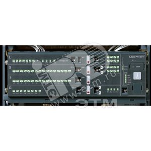
Характеристики
Страна:Германия
Производитель:ABB
Артикул:1SDA058193R1
Ед.измерения:шт
Наименование в прайсе производителя:Расцепитель защиты PR121/P-LSI
Способы получения
Самовывоз: На заказ
Стандартная доставка
Оплата
По счету, онлайн, наличными, по QR-коду
-
Возврат 100 дней
-
Официальный дистрибьютор
-
Центр поддержки 24/7
ЭТМ — участник ассоциации
Честная позиция
Характеристики
Страна:Германия
Производитель:ABB
Артикул:1SDA058193R1
Ед.измерения:шт
Наименование в прайсе производителя:Расцепитель защиты PR121/P-LSI
Описание
Купить Расцепитель защиты PR121/P-LSI в ЭТМ iPRO с доставкой в любой регион России. Если же нужна консультация по товару, обратитесь к своему персональному менеджеру или по телефону +7 (800) 775 17 71 (звонок бесплатный).
Предоставляется гарантия производителя.
Расцепитель защиты PR121/P-LSI: актуальная цена, полные характеристики, описание, фотографии и сертификаты производителей в каталоге ЭТМ iPRO.
Сертификаты
Материалы о товаре
Не забудьте купить
Фотография
Наименование
Производитель
Упак
Доступно сейчас
Цена
Корзина
шт.
Свяжитесь с нами
шт.
Свяжитесь с нами
Заказ по: 1 шт