-
Contents
-
Table of Contents
-
Troubleshooting
-
Bookmarks
Quick Links
POWERWARE
9120
®
User’s Guide
6000VA
www.powerware.com
Related Manuals for Eaton POWERWARE 9120
Summary of Contents for Eaton POWERWARE 9120
-
Page 1
POWERWARE 9120 ® User’s Guide 6000VA www.powerware.com… -
Page 2: User Guide
POWERWARE 9120 6000VA User Guide Important Notice The UPS ground (earth) conductor carries leakage current from the loads in addition to any leakage current generated by the UPS. This UPS generates no more than 1 mA of current. To limit the total leakage current to 3.5 mA, the load leakage must be limited to 2.5 mA.
-
Page 3: If You Have A Question
Power Quality offices section). Eaton Power Quality’s service technicians have in- depth knowledge of the UPS and power problems. Eaton Power Quality may tell you the UPS must be returned. If this happens, we will give you a Return Authorisation (RA) number. When you return a Powerware 9120 to the factory for any reason, please use the original packing material in which your unit was shipped to you.
-
Page 4: Table Of Contents
Table of Contents Safety Instructions ……..2 UPS Features .
-
Page 5: Safety Instructions
For assistance, call Powerware Service or your local Powerware office. If the Powerware 9120 has been damaged during shipment, call your vendor immediately. If the Powerware 9120 is stored, the batteries should be recharged every 6 months. If stored above 25° Celsius, recharge the batteries more often.
-
Page 6: Ups Features
UPS Features The Powerware 9120 provides protection against power problems, including power outages, brownouts, and sudden increases in power. It also provides spike suppression and line noise fil- tering to protect your equipment. Front panel LEDs and an audible alarm keep you aware of the unit’s status.
-
Page 7: Installation
Installation Environment The UPS should be installed in a controlled environment. A controlled environment is one that is indoor, temperature controlled, free from conductive contaminants, dust, fumes and moisture. The UPS is intended for indoor use only. Provide adequate ventilation, 100 mm clearance at the rear of the UPS and 50 mm on the sides of the UPS.
-
Page 8: Rear Panel View
Rear Panel View Fig 2. Powerware 9120 6kVA Rear Panel…
-
Page 9: Connections To Mains And Load
Connections to Mains and Load The installation, wiring and connection must be carried out by qualified personnel only. The installation must comply with all current Wiring Rules and Regulations, Local, State and Federal statutes, Legislation and Regulations. CAUTION ! The UPS contains high voltage and current levels which could injure or kill personnel and damage equipment.
-
Page 10
Fig 4. AC Supply with Separate Bypass Supply Note: 1. Max Cable Size into Terminals is 10sq. mm. Stranded Cable 2. Currents quoted are for 240V AC units 3. For Wiring Diagram refer to Fig 6 Fig 6. AC Supply with Separate Bypass Supply Note: For Terminal Connection refer to Fig 4… -
Page 11
2.3.1 Installing the UPS (cont.) Isolate the Supply service and secure against reclosing. The Input and Output Circuit Breakers located at the rear of the UPS must be in the “OFF” position. Connect to the UPS in accordance with Fig 3 for a Single Supply Input or Fig 4 for a Dual Supply Input. -
Page 12: Quick Startup
3.0 Quick Startup Your Powerware 9120 6kVA UPS is designed for direct connection to a mains supply by a qualified electrican. When input power is connected and switched on the LCD backlight will illuminate and the fan will run, but no output power is available.
-
Page 13: Operation
4.0 Operation This section describes: • The UPS front panel • Standby mode • Turning the UPS on and off • Diagnostic tests • Starting the UPS on battery UPS Front Panel The UPS front panel indicates the UPS status and also identifies potential power problems. Figure 7 shows the UPS front panel indicators and controls.
-
Page 14: Turning The Ups On
Turning the UPS On After the UPS is connected to a power source, the fan turns on and the UPS enters Standby mode. To turn on the UPS, press and hold the button until you hear the UPS beep (approximately one second).
-
Page 15: Configuration
Configuration This section describes how to reconfigure options using the Configuration mode, including: input and output voltage and frequency, site wiring fault, and silencing the alarm. NOTE The UPS has been factory-configured with default settings appropriate for most installations. User configuration is not normally required. Configuration Mode ↵…
-
Page 16
Table 1. Configuration Mode Parameters Parameter LCD Message Description Default Settings Output Voltage Setting O/P V Setting To change the output voltage • Select 208, 220, 230, or 240V for 240V models. For 240V models: You are prompted to save this setting. O/P V= 240V Input Voltage Tolerance Bypass Volt Set… -
Page 17
Table 1. Configuration Mode Parameters (cont.) Parameter LCD Message Description Default Settings ↵ ↵ Manual Battery Test Manual BAT Test To initiate a manual battery test, press the button Battery Test twice when “Manual Battery Test” is displayed on the LCD. -
Page 18: Additional Ups Features
Optional Powerware communication cards Inverter Shutdown The Powerware 9120 includes a port that allows the UPS inverter to be switched off. This feature is designed to be used with Powerware External Maintenance Bypass Switches. Refer to the instructions provided with the switch for further information.
-
Page 19: Communication Slot
Refer to the power management software instructions for using the USB port. Communication Slot The Powerware 9120 UPS has a communication slot that allows quick installation of the optional SNMP/Web adapter or future communication interfaces. These interface adapters extend the capabilities of the Powerware 9120 system to provide compatibility with network and remote moni- toring/management systems.
-
Page 20: Relay Card
Relay Card (optional extra) This interface provides true relay contact output to peripheral devices. Outputs are user-selectable as normally open or normally closed. Table 3. Relay Card (AS/400) Pin Assignment Pin Number Signal Name Definition Direction Isolated common to pins 2 & 3 Line OK Relay contact;…
-
Page 21: Replacing The Batteries
8.0 Replacing the Batteries The Powerware 9120 batteries are user-replaceable and can be replaced while the Powerware 9120 has AC input applied and powers the loads. This means that, if necessary, you can replace the batteries while the UPS is running. Before you replace the batteries, make sure that you read the safety information below.
-
Page 22: How To Replace Internal Batteries
How to Replace Internal Batteries Use the following steps to replace the internal batteries: Remove screws where indicated (a). Using caution not to put stress on the LCD display cable, pull the top panel forward and place it on top of the UPS. Unscrew the bottom panel screws (b).
-
Page 23: Recyling The Used Battery
Pull the upper batteries out and place onto a flat, stable surface. Pull the lower batteries out and place onto a flat, stable surface. Remove the batteries from their cradles. See “Recyling the Used Battery” for proper dispos- Install the new batteries. Reinstall the trays and battery covers.
-
Page 24: Specifications
9.0 Specifications Powerware reserves the right to change specifications without prior notice. This section provides the following specifications for the Powerware 9120 6kVA model: • Electrical input and output • Environmental and safety • Weights and dimensions • Battery Table 4. Electrical Input…
-
Page 25
Table 6. Environmental and Safety 240V Models Operating Temperature 0°C to 40°C 0-1500 metres above sea level 0°C to 35°C 1500-3000 metres above sea level Optimal battery performance: 25°C Storage Temperature -15°C to 50°C Relative Humidity 0-95% noncondensing Operating Altitude Up to 3,000 metres above sea level Audible Noise Less than 55 dBA… -
Page 26: Troubleshooting
10.0 Troubleshooting If you have a question or problem, the troubleshooting table may help (See Table 8). If you need assis- tance, phone Powerware Service or your local Powerware office. Please have the model number and serial number (located on the rear of the unit) available. If the unit must be returned, Powerware will give you a Return Authorisation (RA) number.
-
Page 27
Table 8. Troubleshooting LCD Message or Possible Cause Action Condition UPS does not turn on. The UPS is not correctly Check connections to the power source. connected to the power source. The wall outlet is faulty. Have a qualified electrician test and repair the outlet. -
Page 28
Table 8. Troubleshooting (cont.) LCD Message or Possible Cause Action Condition Low Battery The battery is running low. 2 minutes or less of battery power remains 2 beeps every 5 seconds. (depending on load and battery charge). Prepare for a shutdown. Save your work and turn off your equipment. -
Page 29
Table 8. Troubleshooting (cont.) LCD Message or Possible Cause Action Condition Overcharge Batteries are over-charged. Save your work and turn off your equipment. Constant beep. Turn off the UPS. Contact your service representative. O/P Short Output short circuit. Save your work and turn off your equipment Constant beep. -
Page 30: Warranty
11.0 Warranty WARRANTY Information This Warranty is subject to Eaton Power Quality Pty Ltd (EPQ) standard Conditions of Sale which govern all sales of products by Eaton Power Quality Pty Ltd. EPQ products, in general, are warranted against failure due to faulty materials and/or work- manship for a period of two years from despatch date (ex EPQ store) as per invoice.
-
Page 31
Providing that the batteries are used within the limits as set out in the battery manufacturer’s warranty statement and are provided as an integral part of new equipment, they are guaran- teed for two years, from despatch date as per invoice. A copy of this warranty statement is available on request. -
Page 34: Powerware Australia/New Zealand Offices
Powerware Australia/New Zealand Offices Head Office — Sydney Eaton Power Quality Pty Ltd ABN 82 054 056 709 119-127 Wicks Road North Ryde NSW 2113 Phone: 61-2-9878 5000 Fax: 61-2-9887 2186 National Service and Repair Centre 1300 303 059 Web Site: www.powerware.com…
-
Page 35
You have purchased a UPS that will provide you with many years of service, protecting your equipment from surges, sags, and blackouts. This product incorporates the highest quality standards in engineering, manufacturing and testing, and carries a 2 year warranty against defects in material and workmanship. This product is backed by over 60 years of pride and integrity.

-
Contents
-
Table of Contents
-
Troubleshooting
-
Bookmarks
Quick Links
POWERWARE
9120
®
User’s Guide
700 VA — 3000VA
www.powerware.com
Related Manuals for Eaton Powerware 9120
Summary of Contents for Eaton Powerware 9120
-
Page 1
POWERWARE 9120 ® User’s Guide 700 VA — 3000VA www.powerware.com… -
Page 2
POWERWARE 9120 ® 700, 1000, 1500, 2000 & 3000VA User’s Guide Important Notice The UPS ground (earth) conductor carries leakage current from the loads in addition to any leakage current generated by the UPS. This UPS generates no more than 1 mA of current. -
Page 3
Eaton Powerware may tell you the UPS must be returned. If this happens, we will give you a Return Authorisation (RA) number. When you return a Powerware 9120 to the factory for any reason, please use the original packing material in which your unit was shipped to you. -
Page 4: Table Of Contents
Table of Contents Safety Instructions ……..2 UPS Features ……..3 Quick Startup .
-
Page 5: Safety Instructions
UPS and batteries. Whenever the Powerware 9120 is “On,” there may be dangerous voltage present at the unit’s outlets. This is true because the unit’s battery supplies power even if the unit is not plugged into the wall outlet.
-
Page 6: Ups Features
UPS Features The Powerware 9120 provides protection against power problems, including power outages, brownouts, and sudden increases in power. It also provides spike suppression and line noise fil- tering to protect your equipment. Front panel LEDs and an audible alarm keep you aware of the unit’s status.
-
Page 7
USB Port Communication Port M O D EL N O . : 06250700A I N PU T : 208/ 220/ 230V/ 240V, I N PU T : 24V, 25A O U TPU T U SE W I TH : 2BAT 700 ASSEM BLED I N TAI W AN Inverter Shutdown Connector… -
Page 8
USB Port Communication Port Input Connector IEC C14 10A Fig 4. 2000VA Rear Panel Communication Slot Network Surge Suppression Battery Connector Inverter Shutdown Connector Load Segment 2 2 x Australian 10A Load Segment 1 3 x Australian 10A USB Port Communication Port Input Connector IEC C20 16A… -
Page 9: Quick Startup
2.0 Quick Startup Your Powerware 9120 UPS has a removable power cord. Connect the power cord to the back of the unit and plug the UPS into a wall outlet. The LCD backlight will illuminate and the fan will run, but no output power is available.
-
Page 10: Operation
3.0 Operation This section describes: • The UPS front panel • Turning the UPS on and off • Starting the UPS on battery UPS Front Panel The UPS front panel indicates the UPS status and also identifies potential power problems. Figure 6 shows the UPS front panel indicators and controls.
-
Page 11: Turning The Ups On
Turning the UPS On After the UPS is connected to a power source, the fan turns on and the UPS enters Standby mode. To turn on the UPS, press and hold the button until you hear the UPS beep (approximately one second).
-
Page 12: Configuration
Configuration This section describes how to reconfigure options using the Configuration mode, including: input and output voltage and frequency, site wiring fault, and silencing the alarm. NOTE The UPS has been factory-configured with default settings appropriate for most installations. User configuration is not normally required. Configuration Mode The control buttons ( front panel and Table 1 explains the corresponding options.
-
Page 13
Table 1. Configuration Mode Parameters Parameter LCD Message Output Voltage Setting O/P V Setting Input Voltage Tolerance I/P Bypass Set Input Frequency I/P F Setting High-Efficiency Mode HE Mode Setting Free Run Mode Free Run Mode Alarm Silence Alarm Silence Description To change the output voltage •… -
Page 14
Table 1. Configuration Mode Parameters (cont.) Parameter LCD Message Manual Battery Test Manual Bat Test Manual UPS Test Manual UPS Test Site Wiring Fault Alarm Site Fault Set Modem Support Modem Support Number of Extended Bat Pack Num Set Battery Modules Communications Lock- COM Control Cmds… -
Page 15: Additional Ups Features
Optional SOLA communication cards Inverter Shutdown The Powerware 9120 includes a port that allows the UPS inverter to be switched off. This feature is designed to be used with Eaton powerware External Maintenance Bypass Switches. Refer to the instructions provided with the switch for further information.
-
Page 16: Communication Port
Refer to the power management software instructions for using the USB port. Communication Slot The Powerware 9120 UPS has a communication slot that allows quick installation of the optional SNMP/Web adapter or future communication interfaces. These interface adapters extend the capabilities of the Powerware 9120 system to provide compatibility with network and remote moni- toring/management systems.
-
Page 17: Relay Card
Relay Card This interface provides true relay contact output to peripheral devices. Outputs are user-selectable as normally open or normally closed. Table 2. Relay Card (AS/400) Pin Assignment Pin Number Signal Name Line OK Line Failure Battery Normal Battery Low UPS Alarm UPS On/OK UPS Online/Inverter…
-
Page 18: Replacing The Batteries
7.0 Replacing the Batteries The Powerware 9120 batteries are user-replaceable and can be replaced while the Powerware 9120 has AC input applied and powers the loads. This means that, if necessary, you can replace the batteries while the UPS is running. Before you replace the batteries, make sure that you read the safety information below.
-
Page 19: How To Replace Internal Batteries
How to Replace Internal Batteries Use the following steps to replace the internal batteries: Using caution not to put stress on the LCD display cable, pull the top of the front panel forward. Release the spring latches at the bottom of the front panel and remove it, placing it to the side of the UPS.
-
Page 20: Specifications
8.0 Specifications Eaton Powerware reserves the right to change specifications without prior notice. This section provides the following specifications for the Powerware 9120 models: • Electrical input and output • Environmental and safety • Weights and dimensions • Battery Table 4. Electrical Input…
-
Page 21
Table 6. Environmental and Safety Operating Temperature Storage Temperature Relative Humidity Operating Altitude Audible Noise Safety Conformance Table 7. Weights and Dimensions UPS 240V Models Dimensions (WxDxH) 700-1000 VA: 15.8 x 41.2 x 24.3 cm 1500 VA: 17.0 x 44.4 x 27.5 cm 2000-3000 VA: 21.7 x 47.2 x 36.1 cm Weight 700 VA: 12.6 kg… -
Page 22
Table 8. Battery Configuration Type Charging Table 9. Battery Run Times (in Minutes) Number of Batteries 700 VA UPS Internal Batteries NOTE Battery times are approximate and vary depending on the load configuration and battery charge. 700 VA: (2) 12V, 9 Ah internal batteries; 24 Vdc 1000 VA: (3) 12V, 9 Ah internal batteries;… -
Page 23: Troubleshooting
Troubleshooting If you have a question or problem, the troubleshooting table may help (See Table 10). If you need assistance, phone Eaton Powerware Service or your local Eaton Powerware office. Please have the model number and serial number (located on the rear of the unit) available. If the unit must be returned, Eaton Powerware will give you a Return Authorisation (RA) number.
-
Page 24
Table 10. Troubleshooting LCD Message or Condition UPS does not turn on. LCD panel is blank. UPS does not provide the expected backup time The UPS operates normally, but some or all of the protected equipment is not on. On-Battery 1 beep every 5 seconds. -
Page 25
Table 10. Troubleshooting (cont.) LCD Message or Condition Low Battery 2 beeps every 5 seconds. Replace Battery 3 beeps every 5 seconds. Low Charge 3 beeps every 5 minutes. Output Overload 2 beeps per second. Battery Overload 2 beeps per second. Site Fault 1 beep per second. -
Page 26
Table 10. Troubleshooting (cont.) LCD Message or Condition Over-Charge Constant beep. Charger Failure Output Short Constant beep. High Output Voltage Constant beep. Low Output Voltage Constant beep. High DC Bus 2 beeps per second. Possible Cause Batteries are over-charged. Charger has failed. Output short circuit. -
Page 27: Warranty
10. Warranty WARRANTY Information This Warranty is subject to Eaton Power Quality Pty Ltd (EPQ) standard Conditions of Sale, which govern all sales of products by Eaton Power Quality Pty Ltd. EPQ products, in general, are warranted against failure due to faulty materials and/or workmanship for a period of two years from despatch date (ex EPQ store) as per invoice.
-
Page 28
High grade batteries, designed for Uninterruptible Power Supply (UPS) applications, are supplied by EPQ for use with EPQ UPS equipment. These batteries have a finite life expectancy depending on a number of variables, including rate of discharge, depth of discharge, operating temperature, etc. -
Page 31: Eaton Powerware Australia/New Zealand Offices
Eaton Powerware Australia/New Zealand Offices Head Office — Sydney Eaton Power Quality Pty Ltd 10 Kent Road Mascot NSW 2020 Phone: 61-2-9693 9366 Fax: 61-2-8338 1159 National Service and Repair Centre Web Site: www.powerware.com.au Customer Service Offices Adelaide PO Box 481, Marlestone Business Centre SA 5033 Phone: 08-8347-3622 Fax: 08-8445-6328…
-
Page 32
You have purchased a UPS that will provide you with many years of service, protecting your equipment from surges, sags, and blackouts. This product incorporates the highest quality standards in engineering, manufacturing and testing, and carries a 2 year warranty against defects in material and workmanship. This product is backed by over 60 years of pride and integrity.
This manual is also suitable for:
Pw9120


ИБП Eaton Powerware 9120 применяется там, где нужна наивысшая степень защиты электропитания. Топология двойного преобразования обеспечивает чистое и бесперебойное синусоидальное питание критической нагрузки, а широкие коммуникационные возможности ИБП позволяют легко интегрировать систему электропитания практически в любую структуру – компьютерную сеть или систему управления зданием.
Высокая производительность
 Благодаря технологии двойного преобразования напряжения Eaton 9120 обеспечивает бесперебойное питание критически важных нагрузок, защищая их от всех возможных проблем, возникающих в сети.
Великолепные технические характеристики делают этот ИБП универсальным решением для любых приложений.
Подробнее…
1 Показано 1 — 7 (всего позиций: 7)
-
")
- Eaton Powerware 9120 700 ВА (05147361-5501)
- Мощность: 700 ВА (490 Вт); Входное напряжение: 220,230,240 В; Время работы: 8 мин. (100%)…
")
-
- Eaton Powerware 9120 1000 ВА (05147362-5501)
- Мощность: 1000 ВА (700 Вт); Входное напряжение: 220,230,240 В; Время работы: 8 мин. (100%)…
")
-
- Eaton Powerware 9120 1500 ВА (05147363-5501)
- Мощность: 1500 ВА (1050 Вт); Входное напряжение: 220,230,240 В; Время работы: 7 мин. (100%)…
")
-
- Eaton Powerware 9120 2000 ВА (05147364-5501)
- Мощность: 2000 ВА (1400 Вт); Входное напряжение: 220,230,240 В; Время работы: 12 мин. (100%)…
")
-
- Eaton Powerware 9120 3000 ВА (05147365-5501)
- Мощность: 3000 ВА (2100 Вт); Входное напряжение: 220,230,240 В; Время работы: 8 мин. (100%)…
")
-
- Eaton Powerware 9120 5000 ВА (1018289)
- Мощность: 5000 ВА (3500 Вт); Входное напряжение: 220,230,240 В; Время работы: 10 мин. (100%)…
")
-
- Eaton Powerware 9120 6000 ВА (1018290)
- Мощность: 6000 ВА (4200 Вт); Входное напряжение: 220,230,240 В; Время работы: 7 мин. (100%)…
")
1 Показано 1 — 7 (всего позиций: 7)
Краткое содержание страницы № 1
®
POWERWARE 9120
User’s Guide
700 VA — 3000VA
www.powerware.com
Краткое содержание страницы № 2
® POWERWARE 9120 700, 1000, 1500, 2000 & 3000VA User’s Guide Important Notice The UPS ground (earth) conductor carries leakage current from the loads in addition to any leakage current generated by the UPS. This UPS generates no more than 1 mA of current. To limit the total leakage current to 3.5 mA, the load leakage must be limited to 2.5 mA. The three-wire receptacle that you plug the UPS into must have a good (low- impedance) ground (protective earth) connection to provide a safe path for lea
Краткое содержание страницы № 3
If You Have a Question Customer Support If you have a question or problem, Table 10, Troubleshooting, may help. If you need more help, please have your UPS model number and serial number (on the back label) nearby, and call the Eaton Powerware office nearest you (see the offices section). Eaton Powerwares’ service technicians have in-depth knowledge of the UPS and power problems. Eaton Powerware may tell you the UPS must be returned. If this happens, we will give you a Return Authorisation (RA)
Краткое содержание страницы № 4
1 Table of Contents Safety Instructions . . . . . . . . . . . . . . . . . . . . . . . . . . . . . . . . . .2 1.0 UPS Features . . . . . . . . . . . . . . . . . . . . . . . . . . . . . . . . . . . . .3 2.0 Quick Startup . . . . . . . . . . . . . . . . . . . . . . . . . . . . . . . . . . . . . .6 3.0 Operation . . . . . . . . . . . . . . . . . . . . . . . . . . . . . . . . . . . . . . . . .7 3.1 UPS Front Panel . . . . . . . . . . . . . . . . . . . . . . . . . . . . . . . . . . .7 3.2 Turning the
Краткое содержание страницы № 5
2 Safety Instructions IMPORTANT SAFETY INSTRUCTIONS! SAVE THESE INSTRUCTIONS! This User Guide contains important instructions for your Powerware 9120 that must be followed during installation and maintenance of the UPS and batteries. CAUTION! Whenever the Powerware 9120 is “On,” there may be dangerous voltage present at the unit’s outlets. This is true because the unit’s battery supplies power even if the unit is not plugged into the wall outlet. The unit contains dangerous voltages. To reduce t
Краткое содержание страницы № 6
3 1.0 UPS Features The Powerware 9120 provides protection against power problems, including power outages, brownouts, and sudden increases in power. It also provides spike suppression and line noise fil- tering to protect your equipment. Front panel LEDs and an audible alarm keep you aware of the unit’s status. Use the drawings on this and the following pages to identify features of the unit. Fig 1. Powerware 9120 Controls and Indicators
Краткое содержание страницы № 7
4 Communication Slot USB Port MODEL NO.:06250700A P/N:06250700A INPUT :208/220/230V/240V, Communication Port 50/60Hz, 3.4/3.2/3.0/2.9A INPUT :24V,25A OUTPUT :208/220/230/240V, 50/60Hz 700VA/490W USE WITH:2BAT 700 ASSEMBLED IN TAIWAN 612-09910-00 Network Surge Suppression Fan Battery Connector Inverter Shutdown Connector Load Segment 2 2 x Australian 10A Load Segment 1 2 x Australian 10A Input Connector IEC C14 10A Fig 2. 700VA and 1000VA Rear Panel Communication Slot USB Port Communi
Краткое содержание страницы № 8
5 Communication Slot USB Port Communication Port Network Surge Suppression Battery Connector Fan Inverter Shutdown Connector Load Segment 2 2 x Australian 10A Input Connector Load Segment 1 IEC C14 10A 3 x Australian 10A Fig 4. 2000VA Rear Panel Communication Slot USB Port Communication Port Network Surge Suppression Battery Connector Fan Inverter Shutdown Connector Load Segment 2 2 x Australian 15A Load Segment 1 Input Connector 3 x Australian 15A IEC C20 16A Fig 5. 3000VA Rear Panel
Краткое содержание страницы № 9
6 2.0 Quick Startup Your Powerware 9120 UPS has a removable power cord. Connect the power cord to the back of the unit and plug the UPS into a wall outlet. The LCD backlight will illuminate and the 1 fan will run, but no output power is available. Let the unit charge the battery for at least 3 hours. You may use the unit while the battery 2 charges, but the battery backup runtime will be reduced until the battery is fully charged. Start the Powerware 9120 by pressing and holding the On/Standby b
Краткое содержание страницы № 10
7 3.0 Operation This section describes: • The UPS front panel • Standby mode • Turning the UPS on and off • Diagnostic tests • Starting the UPS on battery 3.1 UPS Front Panel The UPS front panel indicates the UPS status and also identifies potential power problems. Figure 6 shows the UPS front panel indicators and controls. Figure 6. UPS Front Panel NOTE If the alarm beeps or if the indicator is on, see Table 10 in Section 9.0 to identi- fy and correct the problem. To configure parameters throu
Краткое содержание страницы № 11
8 3.2 Turning the UPS On After the UPS is connected to a power source, the fan turns on and the UPS enters Standby mode. To turn on the UPS, press and hold the button until you hear the UPS beep (approximately one second). The LCD briefly displays “On Delay” and the “Power On” indicator illuminates. Then the UPS conducts a self-test, briefly displaying “On BATTERY”. If an alarm condition occurs, see Table 10 in Section 9.0 for helpful hints. When the self-test is complete, the LCD displays “On
Краткое содержание страницы № 12
9 4.0 Configuration This section describes how to reconfigure options using the Configuration mode, including: input and output voltage and frequency, site wiring fault, and silencing the alarm. NOTE The UPS has been factory-configured with default settings appropriate for most installations. User configuration is not normally required. Configuration Mode The control buttons ( and ↵↵ ) are used to modify the UPS configuration. Figure 7 shows the front panel and Table 1 explains the corres
Краткое содержание страницы № 13
10 Table 1. Configuration Mode Parameters Parameter LCD Message Description Default Settings Output Voltage Setting O/P V Setting To change the output voltage • Select 208, 220, 230, or 240V for 240V models. For 240V models: You are prompted to save this setting. O/P V= 230V Input Voltage Tolerance I/P Bypass Set Select the input voltage tolerance range before the UPS I/P Tol=+10%/-15% goes to Battery mode: ±10%, +10%/-15%, or +15%/-20%. You are prompted to save this setting. Input Frequency I/
Краткое содержание страницы № 14
11 Table 1. Configuration Mode Parameters (cont.) Parameter LCD Message Description Default Settings ↵↵ Manual Battery Test Manual Bat Test To initiate a manual battery test, press the button Battery Test twice when “Manual Battery Test” is displayed on the LCD. During the test the LCD displays ON BATTERY. The UPS resets the automatic timer after a manual battery test. The LCD displays “Battery not charged” when UPS test is requested but the battery is not fully charged. ↵↵ Manual UPS Test Manu
Краткое содержание страницы № 15
12 5.0 Additional UPS Features This section describes: • Inverter Shutdown • Network Transient Protector • Load segments • Using the communication port or USB port • Optional SOLA communication cards 5.1 Inverter Shutdown The Powerware 9120 includes a port that allows the UPS inverter to be switched off. This feature is designed to be used with Eaton powerware External Maintenance Bypass Switches. Refer to the instructions provided with the switch for further information. Pin 1 Pin 1Pin 2 Pin 2
Краткое содержание страницы № 16
13 5.4 Communication Port To establish communication between the UPS and a computer, connect your computer to the UPS communication port using the supplied communication cable. When the communication cable is installed, power management software can exchange data with the UPS. The software polls the UPS for detailed information on the status of the power environ- ment. If a power emergency occurs, the software initiates the saving of all data and an orderly shutdown of the equipment. The pin fun
Краткое содержание страницы № 17
14 5.7 Relay Card This interface provides true relay contact output to peripheral devices. Outputs are user-selectable as normally open or normally closed. Table 2. Relay Card (AS/400) Pin Assignment Pin Number Signal Name Definition Direction 1 — Isolated common to pins 2 & 3 — 2 Line OK Relay contact; closed to pin 1 — 3 Line Failure Relay contact; closed to pin 1 — 4 — Isolated common to pins 5 & 6 — 5 Battery Normal Relay contact; closed to pin 4 — 6 Battery Low Relay contact; closed to pin
Краткое содержание страницы № 18
15 7.0 Replacing the Batteries The Powerware 9120 batteries are user-replaceable and can be replaced while the Powerware 9120 has AC input applied and powers the loads. This means that, if necessary, you can replace the batteries while the UPS is running. Before you replace the batteries, make sure that you read the safety information below. Note: If you have a power outage while you are replacing the batteries, the UPS will not be able to run on battery power and your protected equipment will s
Краткое содержание страницы № 19
16 7.1 How to Replace Internal Batteries Use the following steps to replace the internal batteries: 1. Using caution not to put stress on the LCD display cable, pull the top of the front panel forward. Release the spring latches at the bottom of the front panel and remove it, placing it to the side of the UPS. 2. Unscrew the metal battery cover (2000VA model shown). 3. Pull the battery out onto a flat, stable surface (2000VA model shown) 4. Remove the old battery. See “Recycling the Used Battery
Краткое содержание страницы № 20
17 8.0 Specifications Eaton Powerware reserves the right to change specifications without prior notice. This section provides the following specifications for the Powerware 9120 models: • Electrical input and output • Environmental and safety • Weights and dimensions • Battery Table 4. Electrical Input 240V Models Nominal Voltage 240V default; 208, 220, 230, 240V selectable Voltage Range 160-276V for 208, 220, 230, 240V nominal Nominal Frequency 50/60 Hz, ±5% user-selectable Noise Filtering MOV
- О компании
-
- ИБП по сериям
- Eaton 9SX
- Eaton 93PS
- Eaton 93E
- Eaton 9E
- Eaton 9PX (5 — 11 кВА)
- Eaton 9PX (1 — 3 кВА)
- Eaton 93PM G2
- Eaton Protection Station
- Eaton Blade UPS
- Eaton 3S
- Eaton Ellipse Eco
- Eaton Ellipse Pro
- Eaton 5E
- Eaton 5PX Gen2 (1 — 3 кВА)
- Eaton 5S
- Eaton 5SC
- Eaton 5P
- Eaton Power Xpert 9395P
- Eaton 9SX Marine
- Eaton 9130 Marine
- Eaton 9155 Marine
- Eaton 9355 Marine
- Eaton 9390 Marine
- Eaton Power Xpert 9395 Marine
- ENKOM LB1
- ENKOM LB2
- ENKOM LB3
- ENKOM S2S
- ENKOM DXS
- ENKOM S3S
- Eaton 91PS
- Eaton 9PHD Marine
- Eaton 9PHD
- ИБП по мощности
- ИБП до 1 кВА
- 300 ВА
- 500 ВА
- 550 ВА
- 650 ВА
- 700 ВА
- 750 ВА
- 800 ВА
- 850 ВА
- ИБП 1 — 3 кВА
- 1000 ВА
- 1100 ВА
- 1200 ВА
- 1500 ВА
- 1600 ВА
- 2000 ВА
- 2200 ВА
- 3000 ВА
- ИБП 5 — 9 кВА
- 5 кВА
- 6 кВА
- 8 кВА
- 9 кВА
- ИБП 10 — 15 кВА
- 10 кВА
- 11 кВА
- 12 кВА
- 15 кВА
- ИБП 20 — 80 кВА
- 20 кВА
- 30 кВА
- 40 кВА
- 50 кВА
- 60 кВА
- 80 кВА
- ИБП 100 — 300 кВА
- 100 кВА
- 120 кВА
- 150 кВА
- 160 кВА
- 200 кВА
- 250 кВА
- 300 кВА
- ИБП 500 — 1200 кВА
- 500 кВА
- 600 кВА
- 750 кВА
- 900 кВА
- 1000 кВА
- 1200 кВА
- ИБП до 1 кВА
- ИБП по назначению
- ИБП для дома
- ИБП для офиса
- ИБП для бизнеса
- ИБП для ЦОД
- ИБП для насосов
- ИБП для котлов
- ИБП для медицины
- ИБП для сервера
- ИБП для промышленности
- ИБП для морских судов
- ИБП для телекоммуникаций
- ИБП по типу
- Online
- Line Interactive
- Offline
- ИБП по исполнению
- Tower
- Minitower
- Rackmount
- Rack/Tower (универсальные)
- Старые модели (не производятся)
- Опции к оборудованию
- ЗИП для ИБП Eaton
Каталог оборудования
- ИБП по сериям
- Услуги и сервис
- Trade-In
- ИБП в аренду
- Как заказать
- Наши проекты
- Контакты
- Подобрать оборудование
Санкт-Петербург,
Софийская ул. 14 А
Время работы
с 9:00 до 18:00
по будням
Конфигурация:
Tower
Мощность:
5 — 6 кВА
Напряжение:
220 — 240 В
К сожалению, оборудование Eaton 9120 больше не производится и не доступно для заказа.
В качестве альтернативы предлагаем вам рекомендованную производителем замену – Eaton 9SX
- ИБП по сериям
- Eaton 9SX
- Eaton 93PS
- Eaton 93E
- Eaton 9E
- Eaton 9PX (5 — 11 кВА)
- Eaton 9PX (1 — 3 кВА)
- Eaton 93PM G2
- Eaton Protection Station
- Eaton Blade UPS
- Eaton 3S
- Eaton Ellipse Eco
- Eaton Ellipse Pro
- Eaton 5E
- Eaton 5PX Gen2 (1 — 3 кВА)
- Eaton 5S
- Eaton 5SC
- Eaton 5P
- Eaton Power Xpert 9395P
- Eaton 9SX Marine
- Eaton 9130 Marine
- Eaton 9155 Marine
- Eaton 9355 Marine
- Eaton 9390 Marine
- Eaton Power Xpert 9395 Marine
- ENKOM LB1
- ENKOM LB2
- ENKOM LB3
- ENKOM S2S
- ENKOM DXS
- ENKOM S3S
- Eaton 91PS
- Eaton 9PHD Marine
- Eaton 9PHD
- ИБП по мощности
- ИБП до 1 кВА
- 300 ВА
- 500 ВА
- 550 ВА
- 650 ВА
- 700 ВА
- 750 ВА
- 800 ВА
- 850 ВА
- ИБП 1 — 3 кВА
- 1000 ВА
- 1100 ВА
- 1200 ВА
- 1500 ВА
- 1600 ВА
- 2000 ВА
- 2200 ВА
- 3000 ВА
- ИБП 5 — 9 кВА
- 5 кВА
- 6 кВА
- 8 кВА
- 9 кВА
- ИБП 10 — 15 кВА
- 10 кВА
- 11 кВА
- 12 кВА
- 15 кВА
- ИБП 20 — 80 кВА
- 20 кВА
- 30 кВА
- 40 кВА
- 50 кВА
- 60 кВА
- 80 кВА
- ИБП 100 — 300 кВА
- 100 кВА
- 120 кВА
- 150 кВА
- 160 кВА
- 200 кВА
- 250 кВА
- 300 кВА
- ИБП 500 — 1200 кВА
- 500 кВА
- 600 кВА
- 750 кВА
- 900 кВА
- 1000 кВА
- 1200 кВА
- ИБП до 1 кВА
- ИБП по назначению
- ИБП для дома
- ИБП для офиса
- ИБП для бизнеса
- ИБП для ЦОД
- ИБП для насосов
- ИБП для котлов
- ИБП для медицины
- ИБП для сервера
- ИБП для промышленности
- ИБП для морских судов
- ИБП для телекоммуникаций
- ИБП по типу
- Online
- Line Interactive
- Offline
- ИБП по исполнению
- Tower
- Minitower
- Rackmount
- Rack/Tower (универсальные)
- Старые модели (не производятся)
- Опции к оборудованию
- ЗИП для ИБП Eaton
Каталог оборудования
|
Модель |
700 ВА |
1000 ВА |
1500 ВА |
2000 ВА |
3000 ВА |
5000 ВА |
6000 ВА |
|
Код изделия |
05147361-5591 |
05147362-5591 |
05147363-5591 |
05147364-5591 |
05147365-5591 |
1026103 |
1026104 |
|
Мощность (ВА/Вт) |
700/490 |
1000/700 |
1500/1050 |
2000/1400 |
3000/2100 |
5000/3500 |
6000/4200 |
|
Габариты ШxГxВ (мм) |
155 x 410 x 240 |
155 x 410 x 240 |
170 x 445 x 275 |
225 x 470 x 365 |
225 x 470 x 365 |
280 x 580 x 570 |
280 x 580 x 570 |
|
Вес (кг) |
13 |
15 |
20 |
37 |
38 |
91 |
91 |
|
Входной разъем |
IEC320/10A |
IEC320/16A |
Клеммная колодка |
||||
|
Выходные разъемы |
4 x IEC320/10A |
1 x IEC320/16A |
Клеммная колодка |
||||
|
Время автономной работы |
8 мин. |
8 мин. |
7 мин. |
14 мин. |
8 мин. |
10 мин. |
8 мин. |
|
Эксплуатационные параметры |
|||||||
|
Номинальное входное напряжение |
220 / 230 / 240 В переменного тока |
||||||
|
Диапазон входного напряжения |
120 / 140 / 160 — 276 В переменного тока (700 — 3000 ВА) |
||||||
|
Частота |
50 / 60 Гц, выбирается автоматически (± 3 Гц, возможность настройки) |
||||||
|
Входной коэффициент мощности |
> 0,97 (700 — 3000 ВА) |
||||||
|
Номинальное выходное напряжение |
208 / 220 / 230 / 240 В переменного тока |
||||||
|
Отклонение выходного напряжения |
± 2% в режиме online; ± 3% в режиме работы от батарей |
||||||
|
Допустимая перегрузка |
до 125 % в течение 1 минуты, 125 — 150% в течение 10 секунд |
||||||
|
КПД |
> 86% (700 ВА) |
> 88% (1000 — 3000 ВА) |
> 90% (5000 — 6000 ВА) |
||||
|
Пользовательский интерфейс |
|||||||
|
ЖК дисплей |
ЖК дисплей, отображающий настройки и показатели ИБП |
||||||
|
Индикаторы |
Четыре индикатора: ИБП вкл., ИБП на батарее, режим байпаса, аварийный сигнал |
||||||
|
Стандартные информационные порты |
RS232 и USB для всех моделей |
||||||
|
Дополнительно |
Слот для подключения SNMP/Web и релейного адаптеров |
||||||
|
Параметры окружающей среды |
|||||||
|
Рабочая температура |
0°C — +40°C, рекомендуется 20°C — 25°C |
||||||
|
Температура хранения |
-15°C — +40°C |
||||||
|
Высота |
< 3000 м |
||||||
|
Уровень шума на расстоянии 1 метра |
< 45 дБ (700 — 1500 ВА) |
-
Page 1
POWERWARE 9120 ® User’s Guide 6000VA www.powerware.com… -
Page 2: User Guide
POWERWARE 9120 6000VA User Guide Important Notice The UPS ground (earth) conductor carries leakage current from the loads in addition to any leakage current generated by the UPS. This UPS generates no more than 1 mA of current. To limit the total leakage current to 3.5 mA, the load leakage must be limited to 2.5 mA.
-
Page 3: If You Have A Question
Power Quality offices section). Eaton Power Quality’s service technicians have in- depth knowledge of the UPS and power problems. Eaton Power Quality may tell you the UPS must be returned. If this happens, we will give you a Return Authorisation (RA) number. When you return a Powerware 9120 to the factory for any reason, please use the original packing material in which your unit was shipped to you.
-
Page 4: Table Of Contents
Table of Contents Safety Instructions ……..2 UPS Features .
-
Page 5: Safety Instructions
For assistance, call Powerware Service or your local Powerware office. If the Powerware 9120 has been damaged during shipment, call your vendor immediately. If the Powerware 9120 is stored, the batteries should be recharged every 6 months. If stored above 25° Celsius, recharge the batteries more often.
-
Page 6: Ups Features
UPS Features The Powerware 9120 provides protection against power problems, including power outages, brownouts, and sudden increases in power. It also provides spike suppression and line noise fil- tering to protect your equipment. Front panel LEDs and an audible alarm keep you aware of the unit’s status.
-
Page 7: Installation
Installation Environment The UPS should be installed in a controlled environment. A controlled environment is one that is indoor, temperature controlled, free from conductive contaminants, dust, fumes and moisture. The UPS is intended for indoor use only. Provide adequate ventilation, 100 mm clearance at the rear of the UPS and 50 mm on the sides of the UPS.
-
Page 8: Rear Panel View
Rear Panel View Fig 2. Powerware 9120 6kVA Rear Panel…
-
Page 9: Connections To Mains And Load
Connections to Mains and Load The installation, wiring and connection must be carried out by qualified personnel only. The installation must comply with all current Wiring Rules and Regulations, Local, State and Federal statutes, Legislation and Regulations. CAUTION ! The UPS contains high voltage and current levels which could injure or kill personnel and damage equipment.
-
Page 10
Fig 4. AC Supply with Separate Bypass Supply Note: 1. Max Cable Size into Terminals is 10sq. mm. Stranded Cable 2. Currents quoted are for 240V AC units 3. For Wiring Diagram refer to Fig 6 Fig 6. AC Supply with Separate Bypass Supply Note: For Terminal Connection refer to Fig 4… -
Page 11
2.3.1 Installing the UPS (cont.) Isolate the Supply service and secure against reclosing. The Input and Output Circuit Breakers located at the rear of the UPS must be in the “OFF” position. Connect to the UPS in accordance with Fig 3 for a Single Supply Input or Fig 4 for a Dual Supply Input. -
Page 12: Quick Startup
3.0 Quick Startup Your Powerware 9120 6kVA UPS is designed for direct connection to a mains supply by a qualified electrican. When input power is connected and switched on the LCD backlight will illuminate and the fan will run, but no output power is available.
-
Page 13: Operation
4.0 Operation This section describes: • The UPS front panel • Standby mode • Turning the UPS on and off • Diagnostic tests • Starting the UPS on battery UPS Front Panel The UPS front panel indicates the UPS status and also identifies potential power problems. Figure 7 shows the UPS front panel indicators and controls.
-
Page 14: Turning The Ups On
Turning the UPS On After the UPS is connected to a power source, the fan turns on and the UPS enters Standby mode. To turn on the UPS, press and hold the button until you hear the UPS beep (approximately one second).
-
Page 15: Configuration
Configuration This section describes how to reconfigure options using the Configuration mode, including: input and output voltage and frequency, site wiring fault, and silencing the alarm. NOTE The UPS has been factory-configured with default settings appropriate for most installations. User configuration is not normally required. Configuration Mode ↵…
-
Page 16
Table 1. Configuration Mode Parameters Parameter LCD Message Description Default Settings Output Voltage Setting O/P V Setting To change the output voltage • Select 208, 220, 230, or 240V for 240V models. For 240V models: You are prompted to save this setting. O/P V= 240V Input Voltage Tolerance Bypass Volt Set… -
Page 17
Table 1. Configuration Mode Parameters (cont.) Parameter LCD Message Description Default Settings ↵ ↵ Manual Battery Test Manual BAT Test To initiate a manual battery test, press the button Battery Test twice when “Manual Battery Test” is displayed on the LCD. -
Page 18: Additional Ups Features
Optional Powerware communication cards Inverter Shutdown The Powerware 9120 includes a port that allows the UPS inverter to be switched off. This feature is designed to be used with Powerware External Maintenance Bypass Switches. Refer to the instructions provided with the switch for further information.
-
Page 19: Communication Slot
Refer to the power management software instructions for using the USB port. Communication Slot The Powerware 9120 UPS has a communication slot that allows quick installation of the optional SNMP/Web adapter or future communication interfaces. These interface adapters extend the capabilities of the Powerware 9120 system to provide compatibility with network and remote moni- toring/management systems.
-
Page 20: Relay Card
Relay Card (optional extra) This interface provides true relay contact output to peripheral devices. Outputs are user-selectable as normally open or normally closed. Table 3. Relay Card (AS/400) Pin Assignment Pin Number Signal Name Definition Direction Isolated common to pins 2 & 3 Line OK Relay contact;…
-
Page 21: Replacing The Batteries
8.0 Replacing the Batteries The Powerware 9120 batteries are user-replaceable and can be replaced while the Powerware 9120 has AC input applied and powers the loads. This means that, if necessary, you can replace the batteries while the UPS is running. Before you replace the batteries, make sure that you read the safety information below.
-
Page 22: How To Replace Internal Batteries
How to Replace Internal Batteries Use the following steps to replace the internal batteries: Remove screws where indicated (a). Using caution not to put stress on the LCD display cable, pull the top panel forward and place it on top of the UPS. Unscrew the bottom panel screws (b).
-
Page 23: Recyling The Used Battery
Pull the upper batteries out and place onto a flat, stable surface. Pull the lower batteries out and place onto a flat, stable surface. Remove the batteries from their cradles. See “Recyling the Used Battery” for proper dispos- Install the new batteries. Reinstall the trays and battery covers.
-
Page 24: Specifications
9.0 Specifications Powerware reserves the right to change specifications without prior notice. This section provides the following specifications for the Powerware 9120 6kVA model: • Electrical input and output • Environmental and safety • Weights and dimensions • Battery Table 4. Electrical Input…
-
Page 25
Table 6. Environmental and Safety 240V Models Operating Temperature 0°C to 40°C 0-1500 metres above sea level 0°C to 35°C 1500-3000 metres above sea level Optimal battery performance: 25°C Storage Temperature -15°C to 50°C Relative Humidity 0-95% noncondensing Operating Altitude Up to 3,000 metres above sea level Audible Noise Less than 55 dBA… -
Page 26: Troubleshooting
10.0 Troubleshooting If you have a question or problem, the troubleshooting table may help (See Table 8). If you need assis- tance, phone Powerware Service or your local Powerware office. Please have the model number and serial number (located on the rear of the unit) available. If the unit must be returned, Powerware will give you a Return Authorisation (RA) number.
-
Page 27
Table 8. Troubleshooting LCD Message or Possible Cause Action Condition UPS does not turn on. The UPS is not correctly Check connections to the power source. connected to the power source. The wall outlet is faulty. Have a qualified electrician test and repair the outlet. -
Page 28
Table 8. Troubleshooting (cont.) LCD Message or Possible Cause Action Condition Low Battery The battery is running low. 2 minutes or less of battery power remains 2 beeps every 5 seconds. (depending on load and battery charge). Prepare for a shutdown. Save your work and turn off your equipment. -
Page 29
Table 8. Troubleshooting (cont.) LCD Message or Possible Cause Action Condition Overcharge Batteries are over-charged. Save your work and turn off your equipment. Constant beep. Turn off the UPS. Contact your service representative. O/P Short Output short circuit. Save your work and turn off your equipment Constant beep. -
Page 30: Warranty
11.0 Warranty WARRANTY Information This Warranty is subject to Eaton Power Quality Pty Ltd (EPQ) standard Conditions of Sale which govern all sales of products by Eaton Power Quality Pty Ltd. EPQ products, in general, are warranted against failure due to faulty materials and/or work- manship for a period of two years from despatch date (ex EPQ store) as per invoice.
-
Page 31
Providing that the batteries are used within the limits as set out in the battery manufacturer’s warranty statement and are provided as an integral part of new equipment, they are guaran- teed for two years, from despatch date as per invoice. A copy of this warranty statement is available on request. -
Page 34: Powerware Australia/New Zealand Offices
Powerware Australia/New Zealand Offices Head Office — Sydney Eaton Power Quality Pty Ltd ABN 82 054 056 709 119-127 Wicks Road North Ryde NSW 2113 Phone: 61-2-9878 5000 Fax: 61-2-9887 2186 National Service and Repair Centre 1300 303 059 Web Site: www.powerware.com…
-
Page 35
You have purchased a UPS that will provide you with many years of service, protecting your equipment from surges, sags, and blackouts. This product incorporates the highest quality standards in engineering, manufacturing and testing, and carries a 2 year warranty against defects in material and workmanship. This product is backed by over 60 years of pride and integrity.
Найди любой мануал:
Например: Sony VGN-FW460J/T
Вы можете бесплатно скачать Инструкция по эксплуатации для Powerware 9120.
Также вы сможете прочесть онлайн этот документ без скачивания.
Скачать Инструкция по эксплуатации для Powerware 9120
Тип файла
PDF
Размер
1009 Kb
Кол-во страниц
24
Просмотров
7214
Читать онлайн Инструкция по эксплуатации для Powerware 9120 (Страница 1)

Другие Блоки питания Powerware 9120
Топ Powerware Блоки питания
Вопросы
Ранее вы смотрели
Эта страница полезна для вас? Поделитесь ссылкой:
Характеристики UPS ИБП Eaton 9120 6000 ВА (серия Powerware)
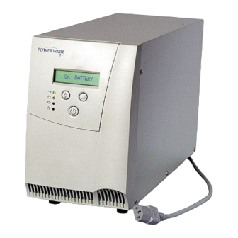
ИБП Eaton 9120 (Powerware PW9120) класса On-line обеспечивает бесперебойное электропитание серверов, сетевого и телекоммуникационного оборудования. Eaton 9120 защищает подключенные системы от всех девяти возможных проблем с электропитанием. Широкие коммуникационные возможности ИБП позволяют легко интегрировать систему электропитания практически в любую структуру – компьютерную сеть или систему управления зданием.
Типичное применение ИБП Eaton 9120 (Powerware PW9120)
- Небольшие сети
- Ответственные серверы
- Другие ответственные области информационных технологий
- Оборудование для управления и контроля технологических процессов
- Телекоммуникационные системы
- Системы безопасности
ИБП Eaton 9120 (Powerware PW9120) регулирует как напряжение, так и частоту без перехода на батареи, что позволяет сохранить их ресурс для тех случаев, когда это действительно необходимо. В сочетании с технологией управления зарядом батарей ABM, увеличивающей срок службы аккумуляторных батарей в два раза, стоимость эксплуатации ИБП не высока.
Увеличение времени автономной работы достигается за счет применения дополнительных внешних батарейных модулей. Функция сегментирования нагрузки позволяет в первую очередь завершить работу менее ответственных систем, отложив момент отключения самого важного оборудования.
Яркий ЖК-дисплей обеспечивает удобную индикацию режимов работы ИБП Eaton 9120 и позволяет легко производить настройку ИБП.
ИБП Eaton 9120 (Powerware PW9120), основные характеристики
| ИБП Eaton 9120 (Powerware PW9120) | 700 | 1000 | 1500 | 2000 | 3000 | 5000 | 6000 |
| Входные параметры UPS | |||||||
| Диапазон входного напряжения без перехода на батареи | 120/140/160 — 276 В при 33/66/100% — нагрузке | 140/160/184 – 276 В 33/66/100% — нагрузка |
|||||
| Частота входного напряжения | 40 … 70 Гц | ||||||
| Входной Км | > 0,97 | > 0,95 | |||||
| Диапазон Uвх для Bypass (програм.) | 184 – 265 | ||||||
| Входной ток | 3 | 4 | 5,7 | 7,7 | 12 | 25 | 30 |
| Выходные параметры UPS | |||||||
| Выходная мощность W | 490 | 700 | 1050 | 1400 | 2100 | 3500 | 4200 |
| Выходное напряжение | 220, 230, 240 В ± 2% (синусоидальной формы) | ||||||
| Выходная частота | 50 ± 0.5% в автономном режиме | ||||||
| КНИ выходного напряжения | < 4% при 100% нелинейной нагрузке более 3000VA < 5% < 3% при 100% линейной нагрузке |
||||||
| Перегрузка | 110% — 125% — 1 мин, 125% — 150% — 10сек | ||||||
| КПД | 88% | ||||||
| Механические параметры | |||||||
| Вес (со встроенными батареями) | 13 кг | 15 кг | 20 кг | 37 кг | 38 кг | 90 кг | |
| Габариты (мм) (Ширина х Глубина х Высота) | 155 * 410 * 240 | 170 * 445 * 275 | 215 * 470 * 365 | 260 * 555 * 570 | |||
| Батареи UPS | |||||||
| Тип батарей | 12V 9AH герметичные, свинцово-кислотные, необслуживаемые | 12V, 7AH | |||||
| Напряжение шины постоянного тока (вольт) | 24 | 36 | 48 | 96 | 240 | ||
| Количество батарей (шт) | 2 | 3 | 4 | 8 | 20 | ||
| Время работы при 100% нагрузке | 8 мин | 8 мин | 7 мин | 12 мин | 8 мин | 10 мин | 7 мин |
| Время заряда | 5 часов до 90% | ||||||
| Диагностика | Автоматическое тестирование и тренировка батарей в процессе работы | ||||||
| Общие параметры | |||||||
| Схема работы | On-Line, двойное преобразование | ||||||
| Индикация | Двухстрочный светодиодный дисплей, светодиодная и звуковая сигнализация | ||||||
| Диагностика | Полное самотестирование при включении питания | ||||||
| Интерфейс | RS-232 DB-9, “сухие” контакты | ||||||
| Подключение к ЛВС | SNMP или WEB карта | ||||||
| Способ подключения | 1 разъем на входе и 4 разъема на выходе, все IEC 320 до 3000 VA | ||||||
| Окружающая среда | |||||||
| Акустический шум @ 1 метр | < 45 dBA | < 50 dBA | < 55 dBA | ||||
| Рабочая температура | 0°C … +40°C | ||||||
| Температура хранения | -15°C … +40°C | ||||||
| Относительная влажность | 20 — 90%, без конденсата |
Параметры внешних блоков аккумуляторных батарей для UPS Eaton 9120 (Powerware PW9120) 6000 ВА
| Емкость | Кол-во[шт] | Габариты(Ш*Г*В) [мм] | Масса [кг] | |
| BAT 6000 | 7 АЧ | 2*20 | 260*555*365 | 125 |
Таблица времен автономной работы UPS Eaton 9120 (Powerware PW9120) 5000-6000VA с внешними блоками батарей, power factor нагрузки взят 0.7, т.е 5000 ВА = 3500 Вт
| Конфигурация/Мощность | 500VA | 1000VA | 2000VA | 3000VA | 4000VA | 5000VA | 6000VA |
| UPS 5000VA | 3,5час | 80мин | 38мин | 23мин | 15мин | 10мин | |
| UPS 5000VA + BAT-6000 | >10час | 5час | 145мин | 90мин | 65мин | 45мин | |
| UPS 5000VA + 2x BAT-6000 | >20час | 8,5час | 5час | 150мин | 120мин | 85мин | |
| UPS 6000VA | >3,5час | 80мин | 38мин | 23мин | 15мин | 11мин | 8мин |
| UPS 6000VA + BAT-6000 | >10час | 5час | 145мин | 90мин | 65мин | 45мин | 35мин |
| UPS 6000VA + 2x BAT-6000 | >20час | 8,5час | 5час | 150мин | 120мин | 85мин | 65мин |