Уровень сложности
Средний
Время на прочтение
10 мин
Количество просмотров 1.3K
Введение
Привет!
Проектирование базы данных — это один из важнейших этапов создания информационной системы. Оно включает в себя определение сущностей, их атрибутов и связей между ними, а также выбор наиболее подходящих типов данных и ограничений целостности.
В данной статье мы рассмотрим процесс проектирования базы данных с нуля (в качестве примера возьмем только один слой БД — витринный, он же Data Mart) с использованием ПО SAP PowerDesigner (далее по тексту — PD). В качестве СУБД мы будем использовать Oracle 19c, но вы можете выбрать любую другую, по вашим потребностям (как — об этом чуть ниже).
Рассмотренный в статье инструмент будет интересен системным аналитикам, архитекторам, разработчикам БД и даже бизнес-аналитикам, поскольку, помимо создания физических и логических моделей, в нем можно рисовать ER-диаграммы, BPMN-модели и многое другое.
Подробное руководство по ПО (в том числе на русском языке): https://help.sap.com/docs/SAP_POWERDESIGNER
Где скачать?
На softoroom можно скачать данное ПО и пользоваться бесплатно для личных нужд.
Описание базовых параметров
Начнем с создания новой модели: File >> New Model >> Model types >> Physical Data Model >> Physical Diagram
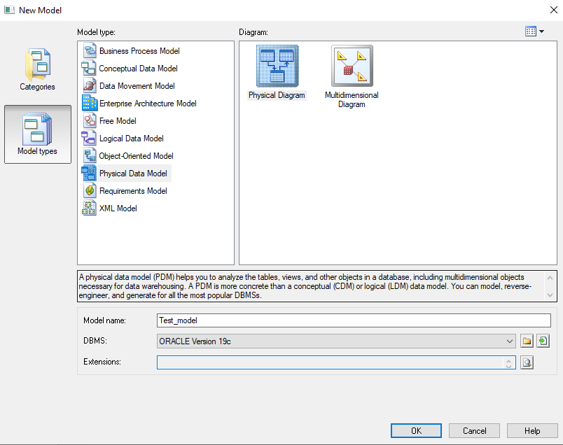
В качестве DBMS (Database Management System, или СУБД) я выбрал Oracle версии 19c. В дальнейшем можно в любое время поменять тип СУБД: Database >> Change current DBMS...
Справа находится Toolbox с объектами физической диаграммы:

Ниже мы рассмотрим только те элементы, которые действительно нам могут пригодиться:
-
Pointer (указатель) — позволяет выделять, перемещать объекты, открывать их свойства;
-
Zoom In (увеличить масштаб) — в качестве аналога можно использовать CTRL + scroll;
-
Zoom Out (уменьшить масштаб) — в качестве аналога можно использовать CTRL + scroll;
-
Properties (свойства) — открывает свойства объекта, в качестве аналога можно использовать двойной щелчок ЛКМ при выбранном инструменте «Pointer»;
-
Delete (удалить) — удаляет выбранный объект, в качестве аналога можно использовать клавишу «Delete» на выделенном объекте;
-
Area (область) — является абстрактным объектом, способным группировать другие объекты. Объекты не принадлежат к области и только группируются в ней;
-
Table (таблица) — создает таблицу в модели;
-
View (представление) — создает представление (view) в модели;
-
Reference (ссылка) — создает связь объектов между собой;
-
Procedure (процедура) — позволяет создать процедуру или функцию для любого объекта (например, для наполнения данными);
-
Note (заметка) — создает объект-заметку, содержащий произвольный текст;
-
Title (заголовок) — создает заголовок модели;
-
Text (текст) — добавляет произвольный текст без рамок;
-
Line (линия) — создает прямую линию для связи объектов без создания reference;
-
Arc (дуга) — создает кривую линию для связи объектов без создания reference.
Создаем объект — таблицу, с использованием соответствующего инструмента из Toolbox. Открываем свойства таблицы:
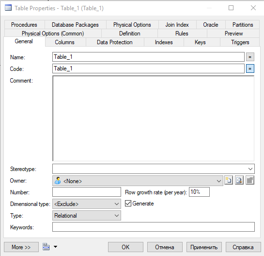
Вкладка General:
-
В поле
Nameвписывается название таблицы. -
По умолчанию в поле
Codeпроливается то же самое значение, что и вName. При необходимости сделать кодовое наименование отличающимся от физического наименования необходимо нажать на иконку=справа. -
В поле
Commentвписывается комментарий к таблице. Комментарий будет отображаться в метаданных таблицы. -
В поле
Ownerнеобходимо выбрать пользователя (схему), где таблица будет расположена. Чтобы создать нового пользователя, необходимо справа нажать на иконкуCreate— откроется окно со свойствами пользователя и вкладкой General:

-
В поле
Nameвписывается логин пользователя, полеCodeзаполнится автоматически. -
В поле
Commentможно добавить комментарий. Например, что данный пользователь будет содержать таблицы витринного слоя. -
В поле
Identification typeможно выбрать тип авторизации для подключения под выбранным пользователем:-
By — пользователь идентифицируется на основе имени пользователя и пароля, которые хранятся в базе данных (необходимо заполнить поле Password);
-
Externally — пользователь идентифицируется на основе своей учетной записи в операционной системе;
-
Globally — пользователь идентифицируется на основе глобальной учетной записи, которая может использоваться для доступа к нескольким базам данных в сети.
-
-
Переходим на вкладку
Privilegesи через иконкуAdd Privilegesвыбираем необходимые доступы. -
На вкладке
Permissionsможно задать разрешения к другим объектам — на select, delete, insert, update и т.п. -
На вкладке
Optionsможно задать tablespace (логическая область хранения данных, размер которой ограничен размером жесткого диска). -
На вкладке
Previewможно посмотреть SQL-скрипт, который генерируется на основе заполненных параметров.

-
В поле
Dimensional typeвыбираем тип измерения для создаваемой таблицы:-
Fact — содержат фактические данные, такие как продажи, количество, доход и т.д. Они связаны с таблицами измерений через ключи, которые являются общими полями между таблицами.
-
Dimension — содержат информацию о измерениях, которые используются для анализа фактических данных. Например, имя покупателя может являться атрибутом в таблице измерений покупателей, а наименование товара, — в таблице измерений товаров.
-
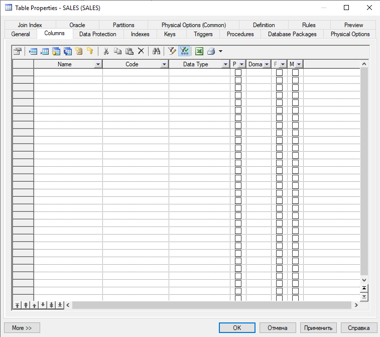
Переходим на вкладку Columns:
-
В поле
Nameвписывается название атрибута, полеCodeзаполнится автоматически. -
В поле
Data Typeвыбирается тип данных из списка. -
Поле
Pявляется флагом для параметра Primary Key. -
Поле
Domainопределяет тип данных, длину, разрядность, обязательность, параметры проверки и бизнес-правила, и может применяться к нескольким столбцам. Домены можно определять для столбцов типа «ид.», «имя», «адрес» или любого другого типа данных, использование которых требуется стандартизировать для нескольких столбцов вашей модели. Выбрать можно только существующий домен, новый требуется создавать отдельно. -
Поле
Fявляется флагом для параметра Foreign Key. Назначить атрибут внешним ключом можно через объектReference(отдельно), либо через вкладкуKeys. -
Поле
Mявляется флагом для параметра Mandatory (признак обязательности заполнения). При заполненном PK проставляется автоматически и не может быть изменен для данного атрибута.
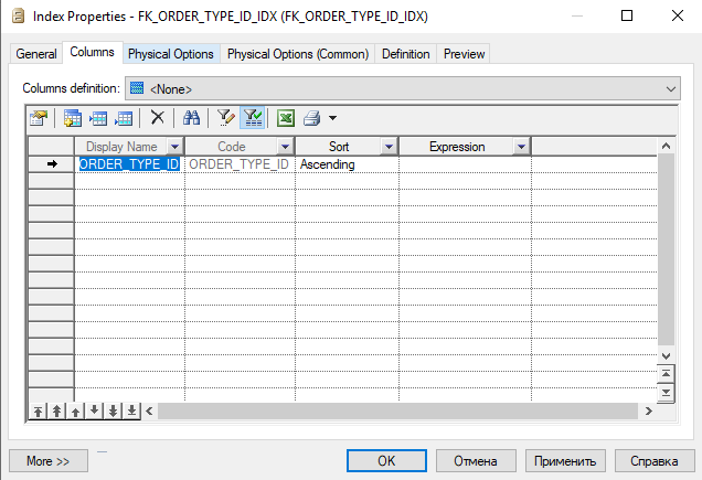
На вкладке Indexes, при необходимости, можно проиндексировать все необходимые атрибуты таблицы.
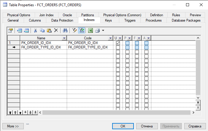
На вкладке Keys отображаются все ключи таблицы. При необходимости, их можно отредактировать или дополнить таблицу новыми.
На вкладке Triggers, при необходимости, можно создать триггер, который будет автоматически выполняться при соблюдении заданного условия.
На вкладке Partitions, при необходимости, можно задать партиционирование для таблицы. Данную вкладку мы подробно рассмотрим позднее.
На вкладке Database Packages, при необходимости, можно создать пакет с процедурами/функциями. Данную вкладку мы подробно рассмотрим позднее.
Импорт из Excel
А теперь жизненная ситуация: допустим, у вас уже есть список таблиц и атрибутов в excel (например, в листах спецификаций). Перебивать все руками — слишком долго и мучительно. Тут на помощь приходит встроенный модуль ExcelImport.
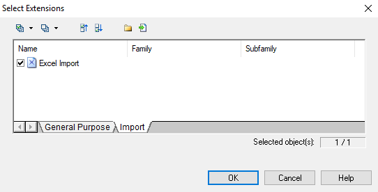
Для начала необходимо создать файл импорта в модели, с помощью которого будем загружать excel-файлы: Model >> Extensions... >> Attach an Extension >> Import >> Excel import >> OK

Далее в Object Browser (панель слева): ПКМ на модели >> Import Excel File... >> Options... >> ДА

 и create symbols in active diagram (визуально отобразит загруженные объекты в модели) и нажимаем ОК.")
Теперь мы готовы импортировать excel-файл. Но для начала необходимо его подготовить, чтобы PD смог корректно распознать в нем данные:
-
Создаем файл с расширением .xlsx с произвольным названием;
-
Создаем 2 листа:
TableиTable.Column -
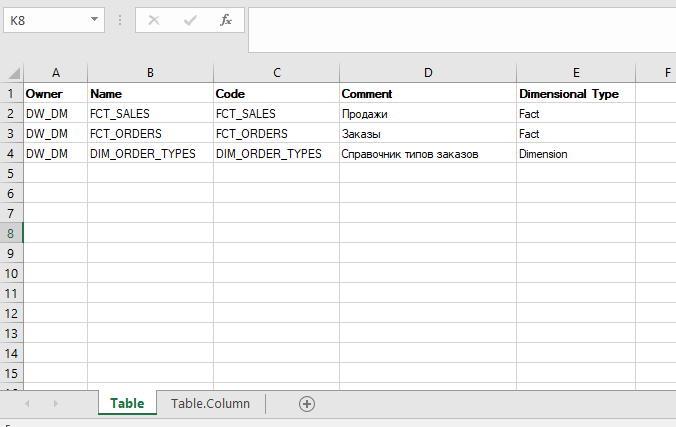
На листе
Tableпрописываем атрибуты:Owner(схема),Name(название таблицы),Code(код таблицы),Comment(комментарий к таблице),Dimensional Type(тип измерения); -
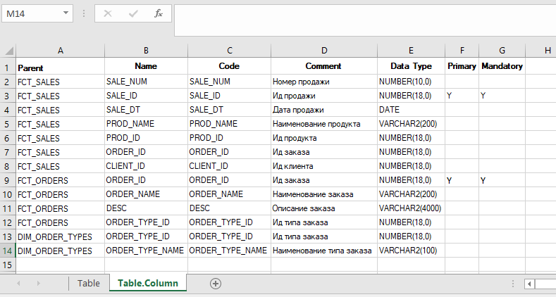
На листе
Table.Columnпрописываем атрибуты:Parent(название таблицы),Name(название атрибута),Code(код атрибута),Comment(комментарий к атрибуту),Data Type(тип данных с указанием размерности),Primary(признак первичного ключа таблицы),Mandatory(признак обязательности заполнения атрибута). -
Наполняем оба листа данными и сохраняем файл.
Возвращаемся в интерфейс PD, нажимаем иконку Select File и выбираем файл, который мы подготовили выше.
Если импорт прошел успешно — появится всплывающее окно с заголовком «import complete«, а также информация о предупреждениях, если что-то не удалось корректно распознать и импортировать. В случае неуспеха — появится соответствующее всплывающее окно. Подробную информацию по ошибкам и предупреждениям можно посмотреть в логах в блоке Output (внизу).

Замечания:
1. В дальнейшем нам не нужно будет заново создавать файл импорта для загрузки того же самого документа — он сохранится, и функция
Import Excel File...будет доступна.2. Если вы хотите загрузить excel-файл с другими наименованиями атрибутов — функция
Auto-map columns to propertiesне сработает, с нее нужно будет убрать галочку и выполнить mapping атрибутов по листам вручную во всплывающих окнах.
Связи таблиц
Теперь, когда у нас есть модель, состоящая из нескольких таблиц, требуется проставить связи между таблицами. Для это воспользуемся параметром Reference из правого Toolbox и проведем линию между таблицами, которые хотим связать:
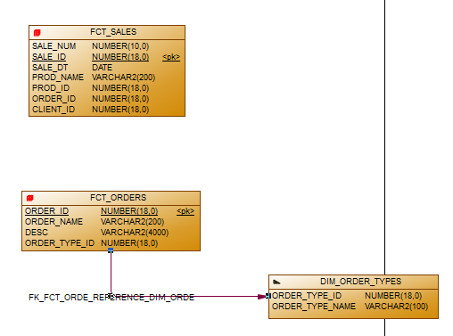
Двойной клик по линии связи открывает ее свойства на вкладке General. Кроме этого, связь появилась и в Object Browser слева в папке References. В свойствах можно увидеть, какая таблица стала родительской, а какая — дочерней.
Стрелка связи должна идти от родительской таблицы к дочерней, если у вас получилось наоборот — можно в этих же свойствах поменять их местами (параметры
Parent tableиChild tableна вкладке General).

На вкладке Integrity можно настроить такие параметры, как Constraint name для нового ключа, Cardinality (тип отношения между таблицами), условие при удалении констреинта (например, удалять каскадно во всех связанных таблицах или только в текущей).
Если вы внимательный, то уже давно заметили, что в справочнике типов заказов не хватает первичного ключа. Т.к. в импортируемом экселе этот параметр не был выбран, мы исправим это руками в интерфейсе — просто в свойствах на вкладке Columns проставим галочку в атрибуте
Primary.
Настройка партиционирования
Теперь настроим партиционирование в таблице FCT_SALES. Идем в свойствах таблицы на вкладку Partitions, видим следующие типы:
-
Range (партиционирование по диапазону) — данные разбиваются на партиции по заданному диапазону значений в определенном столбце таблицы;
-
Composite (комбинированное партиционирование) — комбинация двух или более методов партиционирования для улучшения производительности запросов;
-
Hash (хэш-партиционирование) — данные разбиваются на партиции по хэш-функции, которая определяет номер партиции для каждой строки;
-
List (партиционирование по списку) — данные разбиваются на партиции по заданному списку значений в определенном столбце таблицы;
-
Reference (ссылочное партиционирование) — партиционирование на основе связей между таблицами, где данные в одной таблице разбиваются на партиции, соответствующие данным в другой таблице;
-
System (системное партиционирование) — специальный вид партиционирования, который используется для управления метаданными и системными таблицами в базе данных Oracle. Этот вид партиционирования не предназначен для обычных пользовательских таблиц и используется только для внутренних нужд системы.
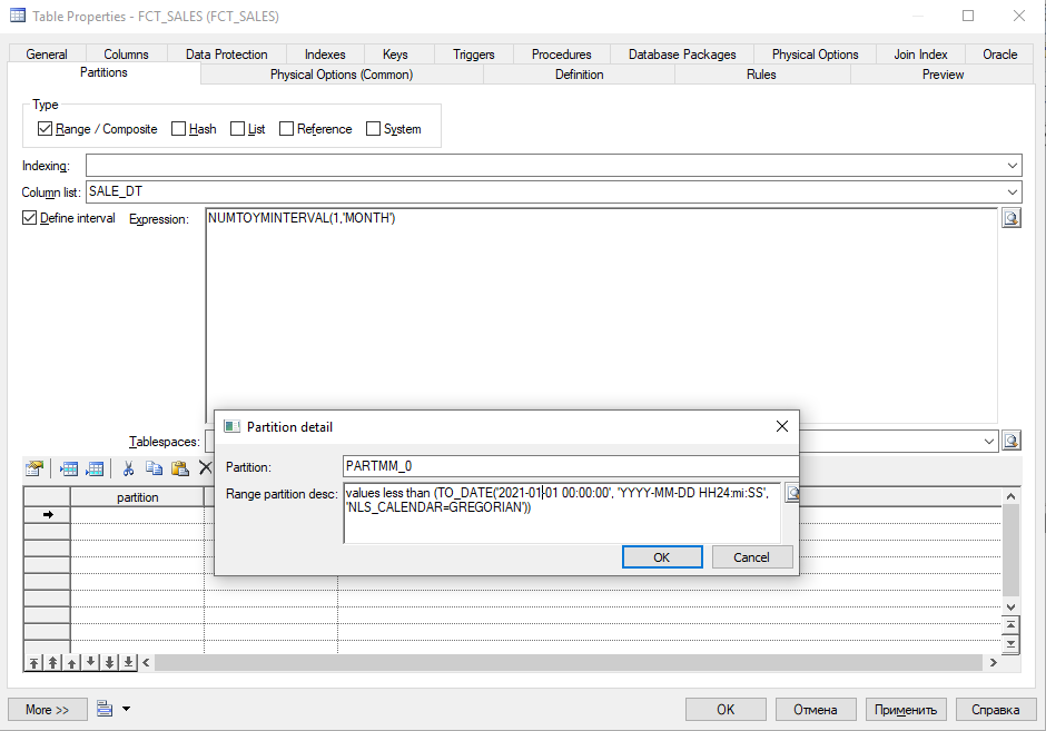
Мы будем создавать интервальные партиции по полю SALE_DT, для этого:
-
Выбираем тип
RangePartitioning; -
В поле
Column listвписываем наш атрибут SALE_DT; -
Задаем необходимый интервал, допустим, месячный. Выбираем параметр
Define intervalи в полеExpressionвписываем значение:NUMTOYMINTERVAL(1,'MONTH'); -
Создаем начальную (граничную) партицию, которая будет содержать архивные данные. Для этого выбираем
Insert a Row >> Properties. В полеPartitionзадаем название начальной партиции — например, PARTMM_0. В полеRange partition descвписываем:values less than (TO_DATE('2021-01-01 00:00:00', 'YYYY-MM-DD HH24:mi:SS', 'NLS_CALENDAR=GREGORIAN')) -
Нажимаем
Применитьдля сохранения изменений.
Создание пакета (Package)
Поскольку в примере мы проектируем витринный слой, помимо него в БД должен быть слой оперативных данных и/или слой детальных данных, из которого с помощью ETL-процесса можно наполнить данными наши витрины. Предположим, что данные мы возьмем из оперативного слоя ODS.
Возвращаемся в свойства таблицы и идем на вкладку Database Packages. Ранее мы не создавали пакеты, поэтому выбираем Create an Object.
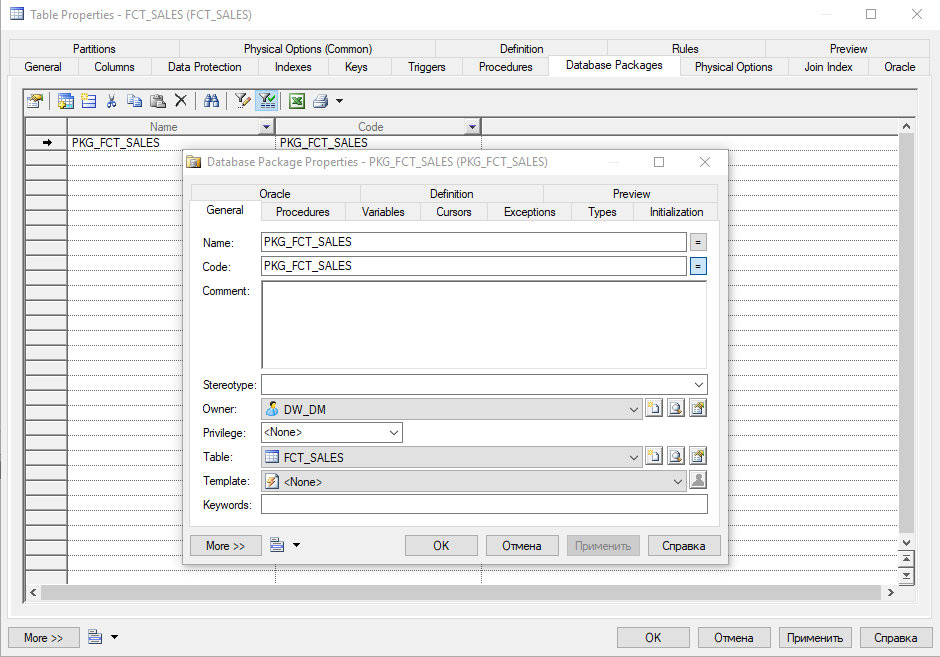
На вкладке General мы задаем параметры Name и Owner и переходим ко вкладке Procedures, где мы создадим процедуру, наполняющую нашу таблицу. На данной вкладке аналогично выбираем Create an Object, в открывшемся окне на вкладке General задаем параметры Name и Type = «Procedure».
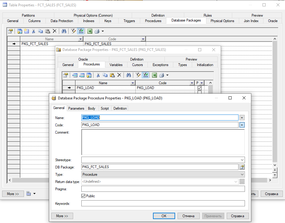
Переходим во вкладку Body. Здесь у нас располагается тело процедуры между ключевыми словами begin и end.

После сохранения всех изменений в окне свойств пакета переходим на вкладку Preview и смотрим на финальный вид скрипта для проверки его корректности:
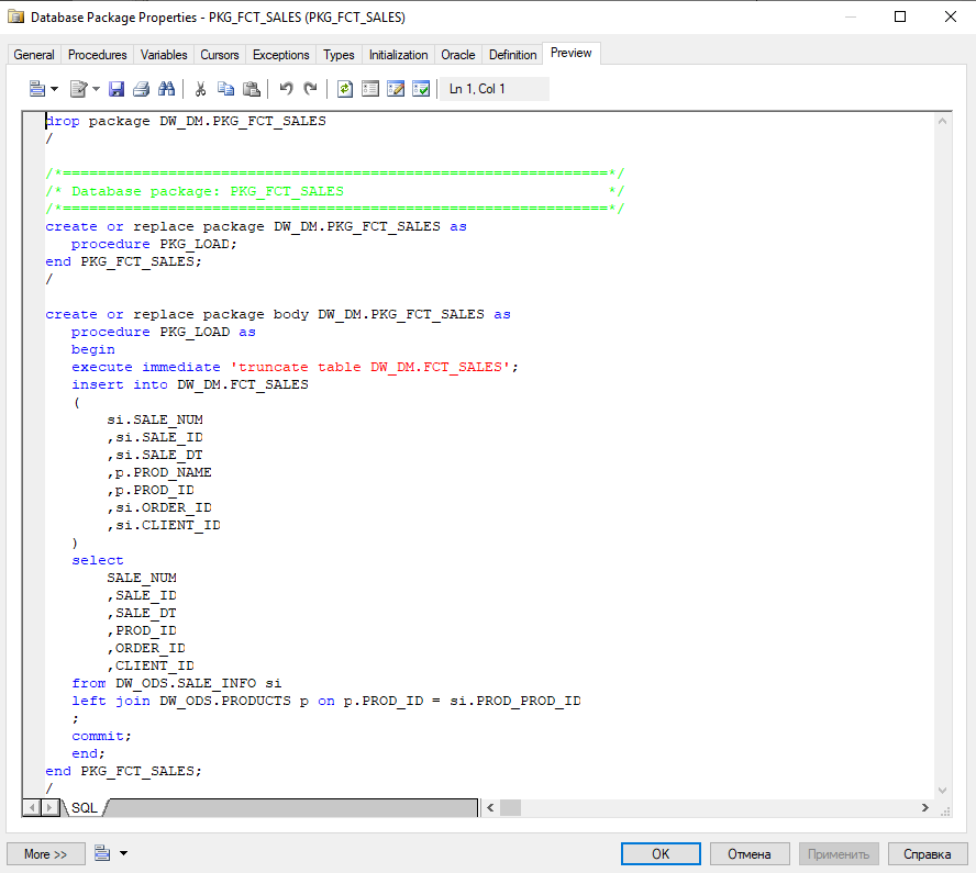
Для остальных объектов создавать пакеты мы не будем, одного вполне достаточно для наглядной демонстрации функционала.
Генерация скрипта
Теперь мы готовы к тому, чтобы экспортировать скрипт для формирования нашего слоя. На верхней панели выбираем: Database >> Generate Database...
На вкладке General указываем путь, по которому будет сгенерирован SQL-файл, и его название.
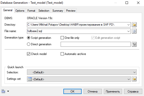
Для базовой генерации этого достаточно, но если нужно кастомизировать — можно поиграться с настройками. Например, чтобы каждый объект генерировался в отдельный файл, достаточно убрать галочку с параметра One file only. Параметр Check model автоматически проверяет модель на предмет ошибок, и, в случае обнаружения критичных, выдает лог с указанием на проблемные места, файл при этом не создастся. Не рекомендую отключать данный параметр во избежание генерации некорретных скриптов.
На вкладке Format можно настроить такие параметры, как Owner prefix (префикс схемы), Title (комментарии по коду с заголовками) и даже Character case (регистр символов в коде). На вкладке Selection можно выбрать конкретные объекты модели, если вам не требуется генерация всего скоупа.

Представим ситуацию, что у вас тестовая среда, и вам необходимо сгенерировать туда произвольные данные. PowerDesigner с этим тоже поможет: Database >> Generate Test Data...
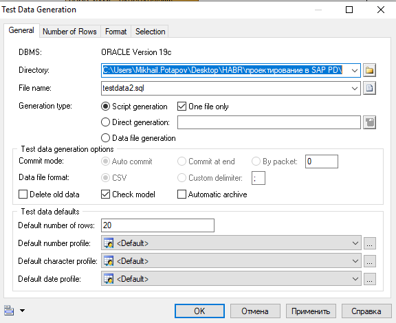
Помимо стандартного выбора пути и названия файла, здесь можно задать и другие интересные функции. Например, задать необходимое количество строк для всех таблиц. В параметрах Default number profile, Default character profile и Default data profile можно задать определенные значения или интервалы значений, если это необходимо. Если вам нужно в каждой таблице задать свое количество записей — на вкладке Number of Rows можно это сделать.
Сохранение
Ну и финально — про сохранение. Сохранить файл с моделью в формате .pdm можно стандартно через: File >> Save As...
Если сохранить нужно в другом формате — например, изображением в .png, то тогда нужно выделить все объекты визуальной модели (CTRL+A) и далее: Edit >> Export Image...
Заключение
Как мы убедились из описания выше, инструмент достаточно многофункциональный, а затронули мы лишь малую часть его возможностей. К сожалению, все функции описать в одной статье не получится, поэтому не бойтесь изучать его самостоятельно. Если у вас был опыт взаимодействия с данным ПО — поделитесь своим опытом и мнением в комментариях.
- Home
- Resources
- Documentation

PowerDesigner 12.6
New Features

PowerDesigner 16.6
Installation Guide

PowerDesigner 16.6
Installation Guide

PowerDesigner 16.6
Data Modeling
PowerDesigner 16.6
Enterprise Architecture Modeling

PowerDesigner 16.6
Data Movement Modeling

PowerDesigner 16.6
Object-Oriented Modeling

PowerDesigner 16.6
Business Process Modeling

PowerDesigner 16.6
XML Modeling

PowerDesigner Web
Customizing PowerDesigner

PowerDesigner Quick Reference
- Manuals
- Brands
- Sybase Manuals
- Software
- Powerdesigner 7.5
- User manual
-
Contents
-
Table of Contents
-
Bookmarks
Quick Links
O
O
M
BJECT
RIENTED
ODEL
User’s Guide
POWERDESIGNER 7.5
Related Manuals for Sybase Powerdesigner 7.5
Summary of Contents for Sybase Powerdesigner 7.5
-
Page 1
BJECT RIENTED ODEL User’s Guide POWERDESIGNER 7.5… -
Page 2
Copyright (c) 1988–2000 Sybase, Inc. All rights reserved. Information in this manual may change without notice and does not represent a commitment on the part of Sybase, Inc. and its subsidiaries. The software described in this manual is provided by Sybase, Inc. under a Sybase License agreement. The software may be used only in accordance with the terms of the agreement. -
Page 3: Table Of Contents
Contents About This Book ………………..ix Object-Oriented Model Basics ……….1 Functional overview …………..2 UML and object-oriented modeling ……….. 3 What is an OOM? …………..4 Objects in an OOM …………..5 Creating a new OOM …………..6 Opening an existing OOM…………8 Defining OOM model options…………
-
Page 4
Preview the code of an interface ……..45 Displaying text in interface symbols ……… 46 Defining attributes …………..48 Attribute properties …………49 Analyzing attribute properties ……….. 50 Creating an attribute…………51 Modifying attribute properties ……….. 54 Attaching an attribute to a domain……..57 Copying an attribute to another class ……. -
Page 5
Creating a dependency ……….109 Modifying dependency properties……..111 Displaying text in dependency symbols……112 Defining realizations………….. 114 Realization properties…………. 114 Creating a realization…………115 Modifying realization properties ……..116 Displaying text in realization symbols ……118 Defining domains …………..120 Domain properties ………… -
Page 6
Reverse engineering PowerBuilder options ….166 Loading a PowerBuilder library model in the workspace …………..168 Reverse engineering objects from a PowerBuilder application ……….169 Reverse engineering objects from SRU files ….171 Reverse engineering XML ………… 174 Reverse engineering XML options ……… 174 Reverse engineering XML files …….. -
Page 7
Translating OOM data types for a PDM…….. 217 Translating Java data types for a PDM ……217 Generating a PDM from an OOM ……… 218 Generating and updating a PDM ……..218 Defining PDM generation options……..220 Object selection parameters……….. 220 Generating a new PDM ………. -
Page 8
viii… -
Page 9: About This Book
About This Book This book describes the PowerDesigner Object-Oriented Model environment. Subject It shows you how to do the following: Build an Object-Oriented Model (OOM) Use classes, packages, and other modeling objects Verify the model and import a Rose model Generate a Conceptual Data Model and a Physical Data Model from the Reverse engineer Java files Generate Java source files…
-
Page 10
About This Book To help you do your work more easily, this book is divided into chapters that focus on particular goals. If you want to Use these parts of the book Learn about the environment Object-Oriented Model Basics Build an object-oriented model Building a Object-Oriented Model Verifying the model and Managing Object-Oriented Models… -
Page 11: Object-Oriented Model Basics
C H A P T E R Object-Oriented Model Basics About this chapter This chapter presents the PowerDesigner Object-Oriented Model. It provides you with an introduction to the basic notions of object-oriented modeling and the Unified Modeling Language (UML). Contents Topic Page Functional overview…
-
Page 12: Functional Overview
Functional overview Functional overview PowerDesigner Object-Oriented Model is a powerful design tool for object- oriented modeling. It gives you all the advantages of a graphical object design implementation. With this product, you can: Build an Object-Oriented Model (OOM) Generate Java class source files (.java) Generate PowerBuilder objects Reverse engineer Java files (.class, .java, or .jar) Reverse engineer PowerBuilder objects…
-
Page 13: Uml And Object-Oriented Modeling
Chapter 1 Object-Oriented Model Basics UML and object-oriented modeling What is UML? UML (The Unified Modeling Language) is a modeling language aimed at defining standards for object-oriented modeling. UML has become a standardized language largely through the work of the OMG (Object Management Group), a group composed of individuals and representatives of companies involved in object-oriented projects.
-
Page 14: What Is An Oom
What is an OOM? What is an OOM? An OOM contains a set of packages, classes, interfaces, and their relationships. These objects together form a class structure that is the logical design view of all (or part of) a software system. An OOM is essentially a static conceptual model of a software system.
-
Page 15: Objects In An Oom
Chapter 1 Object-Oriented Model Basics Objects in an OOM An OOM represents the interaction of the following objects: Selection Object Tool Description Package General purpose sub-set used to organize objects into groups Class Set of objects that share the same attributes, operations, methods, and relationships Interface Collection of operations used to specify the…
-
Page 16: Creating A New Oom
Creating a new OOM Creating a new OOM Creating an OOM requires that you do the following: Open a new file Give the OOM a name and a code After you create an OOM, you can enrich its definition by entering properties and associating objects.
-
Page 17
Chapter 1 Object-Oriented Model Basics Click OK. If you were working on an existing workspace, PowerDesigner opens an new OOM. If there was no workspace open, PowerDesigner opens a new workspace and a new OOM. Select Model Model Properties. Right-click any empty space in the diagram and select Model Properties from the contextual menu. -
Page 18: Opening An Existing Oom
Opening an existing OOM Opening an existing OOM An OOM has the file extension .OOM. To open an existing OOM: Select File Open. Click the Open tool. A standard Windows file selection dialog box appears. Select a file with the .OOM extension. Click OK.
-
Page 19: Defining Oom Model Options
Chapter 1 Object-Oriented Model Basics Defining OOM model options You can set model options and naming conventions that apply to all objects in the model. You can also set naming conventions for each type of object in your model. You define OOM model options from the model options dialog box. You can set options that apply to the following OOM objects: Classes Default data types…
-
Page 20
Defining OOM model options Your choice of whether or not to enforce domain and attribute non- divergence has the following results: Non-divergence Result Not enforced Attributes that are divergent from the domain definition can remain attached to the domain Enforced Attributes that are divergent from the domain (for certain attribute properties) must be detached from the domain If you modify domain non-divergence options, these changes apply only to… -
Page 21: Defining Oom Properties
Chapter 1 Object-Oriented Model Basics Defining OOM properties The Model property sheet displays the definition of the current model. From this property sheet you can modify the model definition. A OOM has the following model properties: Property Description Length Name Name for the model Code Code for the model.
-
Page 22
Defining OOM properties… -
Page 23: Building An Object-Oriented Model
C H A P T E R Building an Object-Oriented Model About this chapter This chapter describes how to build an Object-Oriented Model (OOM). It explains the role of each object in an OOM and how to create and modify objects.
-
Page 24: Defining Packages
Defining packages Defining packages A package is a general purpose mechanism for organizing elements into groups. When you are working with large models, you can split any model into smaller subdivisions in order to avoid manipulating the entire set of data of the model.
-
Page 25: Displaying Text In Package Symbols
Chapter 2 Building an Object-Oriented Model Displaying text in package symbols You can define the following display preferences for a package: Preference Description Show stereotypes When selected, displays the stereotype of the package Show constraints When selected, displays the constraints (types of business rule) that are attached to the package You modify the display preferences for a package in the Display Preferences dialog box.
-
Page 26
Defining packages The package display preferences page appears. Modify the package display preferences. Click OK. -
Page 27: Defining Classes
Chapter 2 Building an Object-Oriented Model Defining classes A class is a description of a set of objects that have a similar structure and behavior, and share the same attributes, operations, relationships, and semantics. A class usually implements one or more interfaces. Classes are the main building blocks of an OOM.
-
Page 28: Class Properties
Defining classes Class properties A class has the following general properties: Maximum Property Description length Name Name of the class Code Reference name for the class Comment Descriptive comment for the class — Stereotype Subclassification of a class derived from an existing —…
-
Page 29: Analyzing Class Properties
Chapter 2 Building an Object-Oriented Model Analyzing class properties The following class properties each have several default values from which you can select from: Stereotype Type Visibility Cardinality Stereotype Stereotypes are classes that are derived from existing classes but that are specific to a particular problem.
-
Page 30
Defining classes Default stereotypes You can declare a class to be one of the following stereotypes: Stereotype Description actor Coherent set of roles that users of use cases play when interacting with the use cases enumeration List of named values used as the range of a particular attribute type exception Exception class. -
Page 31: Creating A Class
Chapter 2 Building an Object-Oriented Model Visibility The visibility of a class refers to the way in which it can be seen by other objects. A class that is visible to another object may influence the structure or behavior of the object, or similarly, its own properties may be affected by the other object.
-
Page 32
Defining classes Creating a class from the Browser To create a class from the Browser: Right-click the Classes category in the Browser. Select New from the contextual menu. The property sheet of the class appears. Type a class name and a class code. Click OK. -
Page 33: Inner Classes
Chapter 2 Building an Object-Oriented Model Creating a class from a diagram To create a class in a diagram: Click the Class tool in the palette toolbar. Click anywhere in the diagram. The following symbol appears at the click position: At creation, a class is named Classn, where n is a number assigned in the order of the creation of objects.
-
Page 34
Defining classes Attaching an inner class to a class You attach an inner class to a class (or interface) from the Inner Classes page of the class (or interface) property sheet. To declare an inner class within a class: Double-click a class in the model. The class property sheet opens to the General page. -
Page 35
Chapter 2 Building an Object-Oriented Model The classes appear in the list of inner classes for the current class, and the definition of the classes are added to the current class definition. Click the Code Preview tab to visualize the inner class definitions within the current class: Click OK. -
Page 36
Defining classes Detaching an inner class from a class Once you have attached an inner class to a class, to remove its declaration from the class you must use detach it. To detach an inner class from a class: Double-click a class in the model. The class property sheet opens to the General page. -
Page 37: Classifiers
Chapter 2 Building an Object-Oriented Model Classifiers A classifier, in UML terminology, is a mechanism that has structural (attributes) and behavioral (operations) features. A class is the most important classifier, but all objects that can have instances, such as interfaces or associations, are classifiers.
-
Page 38
Defining classes The class property sheet appears. Type or select class properties. Click on a page tab. Type or select class properties as required. Click OK. Modifying class properties from the list of classes The list of classes includes all classes attached to the current model or package. -
Page 39: Adding Objects To A Class
Chapter 2 Building an Object-Oriented Model An arrow appears at the beginning of the line. Modify any of the properties of the class directly in the list. Click OK. Adding objects to a class You can add an object to a class, that already exists in the model, but which belongs to another class.
-
Page 40
Defining classes Adding an attribute to a class An attribute is a named property of an object that defines the characteristics of the object. You can add attributes that already exist in the model and which belong to other objects. v To add an attribute to a class: Double-click a class in the model. -
Page 41
Chapter 2 Building an Object-Oriented Model The Selection window appears. It contains a list of all the attributes that exist in the model, with the exception of those that already belong to the class. Select the attributes that you want to add to the class. Use the Select All tool to add all the attributes in the list to the class. -
Page 42
Defining classes The Operations page appears. Click the Add Operations tool. The Selection window appears. It contains a list of all the operations that exist in the model, with the exception of those that already belong to the class. Select the operations that you want to add to the class. Click OK. -
Page 43: Preview The Code Of A Class Or An Interface
Chapter 2 Building an Object-Oriented Model The operations are added to the class and appear in the list of operations for the class. Click OK. Preview the code of a class or an interface You can preview the code of a class or an interface in the Code Preview page of the Property sheet of a class or an interface.
-
Page 44: Displaying Text In Class Symbols
Defining classes Displaying text in class symbols You can define the following display preferences for a class: Preference Description Show attributes Displays all the attributes of the class, or limits the number displayed to a maximum that you specify in the Limit box Show operations Displays all the operations of the class, or limits the number displayed to a maximum that you specify in the Limit box…
-
Page 45
Chapter 2 Building an Object-Oriented Model The class display preferences page appears. Modify the class display preferences. Click OK. -
Page 46: Defining Interfaces
Defining interfaces Defining interfaces An interface is a type of class that is similar to a class but which is used to implement the specification of an abstraction of a class. An interface is a collection of operations used to specify the externally visible behavior of a class.
-
Page 47: Analyzing Interface Properties
Chapter 2 Building an Object-Oriented Model An interface definition also includes the following properties, which are defined on associated property sheets: Property Description Attribute Defines the characteristics of an interface Operations Carries out a service that effects behavior Business rules A rule that your business follows.
-
Page 48
Defining interfaces The property sheet of the interface appears. Type an interface name and an interface code. Click OK. A new interface is created in the Interfaces category. Creating an interface from the list of interfaces To create an interface by inserting it in the list: Select Model Interfaces. -
Page 49: Modifying Interface Properties
Chapter 2 Building an Object-Oriented Model The following symbol appears at the click position: At creation, an interface is named Intfn, where n is a number assigned in the order of the creation of objects. Click the Pointer tool in the palette toolbar. Double-click the new interface symbol in the diagram.
-
Page 50
Defining interfaces The interface property sheet opens to the General page. Opening property sheets at last accessed page Property sheets open to the General page by default. However, you can choose to open property sheets at the last page accessed by selecting Tools Options Dialog, and selecting the option Keep Last Tab in the Property Sheets groupbox. -
Page 51: Adding Inner Classes To An Interface
Chapter 2 Building an Object-Oriented Model The list of interfaces appears. Click the interface that you want to modify. An arrow appears at the beginning of the line. Modify any of the properties of the interface directly in the list. Click OK.
-
Page 52
Defining interfaces You can add the following objects to an interface: Object Description Attribute Named property of an interface that defines the characteristics of an interface Operation Implementation of a service that can be requested from any object of the interface in order to affect behavior Business rule Written statement specifying what the information system must do or how it must be structured to support business needs… -
Page 53
Chapter 2 Building an Object-Oriented Model The Attributes page appears. Click the Add Attributes tool. The Selection window appears. It contains a list of all the attributes that exist in the model, with the exception of those that already belong to the interface. -
Page 54
Defining interfaces Click OK. Adding an operation to an interface An operation is the implementation of a service that can be requested from any object of the class in order to affect behavior. You can add operations that already exist in the model and which belong to other objects. -
Page 55: Preview The Code Of An Interface
Chapter 2 Building an Object-Oriented Model The Selection window appears. It contains a list of all the operations that exist in the model, with the exception of those that already belong to the interface. Select the operations that you want to add to the interface. Click OK.
-
Page 56: Displaying Text In Interface Symbols
Defining interfaces The Code Preview page appears. Click OK. Displaying text in interface symbols You can define the following display preferences for an interface: Preference Description Show attributes Displays all the attributes of the interface, or limits the number displayed to a maximum that you specify in the Limit Show operations Displays all the operations of the interface, or limits the number displayed to a maximum that you specify in the Limit…
-
Page 57
Chapter 2 Building an Object-Oriented Model To modify the interface display preferences: Select Tools Display Preferences. Right-click the diagram background and select Display Preferences from the contextual menu. The Display Preferences dialog box appears. Expand the Object View node in the Category list. Select Interface. -
Page 58: Defining Attributes
Defining attributes Defining attributes Attributes define the characteristics of a class. A class may have none or several attributes. An attribute is a named property of a class that describes the range of values that instances of the property may hold. Each object in a class has the same attributes, but the values of the attributes may be different.
-
Page 59: Attribute Properties
Chapter 2 Building an Object-Oriented Model Attribute properties An attribute has the following properties: Maximum Property Description length Parent Object to which the attribute belongs to Name Name of the attribute Code Reference name for the attribute Comment Descriptive comment for the attribute —…
-
Page 60: Analyzing Attribute Properties
Defining attributes An attribute definition also includes business rules, which are defined on associated property sheets. Analyzing attribute properties The following attribute properties each have several default values from which you can select from: Data Type Visibility Multiplicity Data Type You can select one of the following instances as a data type for an attribute: Boolean Byte…
-
Page 61: Creating An Attribute
One to one 1..* One to infinity Infinity You can change the default format of cardinalities from the registry: HKEY_CURRENT_USER\Software\Sybase\PowerDesigner 7\ModelOptions\Cld MultiplicityNotation = 1 (0..1) or 2 (0,1) Creating an attribute There are three ways to create an attribute: Create an attribute symbol in the Browser…
-
Page 62
Defining attributes The property sheet of the attribute appears. Type an attribute name and an attribute code. Click OK. A new attribute is created in the Attributes category. Creating an attribute from the list of attributes To create an attribute by inserting it in the list: Select Model Attributes. -
Page 63
Chapter 2 Building an Object-Oriented Model Type an attribute name and an attribute code. Click the Stereotype column. Select a stereotype from the Stereotype dropdown listbox. Type a stereotype in the Stereotype column. Click the Data Type column. Select a data type from the Data Type dropdown listbox. Type a data type in the Data Type column. -
Page 64: Modifying Attribute Properties
Defining attributes The Attributes page appears. It lists attributes defined for the class. Click a blank line in the list. Click the Add a Row tool. An arrow appears at the beginning of the line. Type an attribute name and an attribute code. Click OK.
-
Page 65
Chapter 2 Building an Object-Oriented Model Modifying attribute properties from its property sheet The attribute property sheet displays the definition of the attribute, which you can modify. v To modify attribute properties from its property sheet: Double-click the attribute in the model. The attribute property sheet appears. -
Page 66
Defining attributes The general properties of the attribute, in addition to those on the general page, appear. Type or select attribute properties as required. Click OK. Modifying attribute properties from the list of attributes The list of attributes includes all attributes attached to the current model. You can modify the attribute properties from the list. -
Page 67: Attaching An Attribute To A Domain
Chapter 2 Building an Object-Oriented Model The list of attributes appears. Click the attribute that you want to modify. An arrow appears at the beginning of the line. Modify any of the properties of the attribute directly in the list. Click OK.
-
Page 68
Defining attributes The attribute property sheet opens to the General page. Opening property sheets at last accessed page Property sheets open to the General page by default. However, you can choose to open property sheets at the last page accessed by selecting Tools Options Dialog, and selecting the option Keep Last Tab in the Property Sheets groupbox. -
Page 69: Copying An Attribute To Another Class
Chapter 2 Building an Object-Oriented Model Copying an attribute to another class You can copy an attribute from one class and add it to another class. If the class already contains an attribute with the same name or code as the copied attribute, the copied attribute is renamed.
-
Page 70: Displaying Text In Attribute Symbols
Defining attributes Displaying text in attribute symbols An attribute has the following display preferences: Preference Description Show visibility Displays the attribute as an icon, with markers, or using keywords Show datatype When selected, displays the datatype of the attribute in the attribute symbol Show initial value When selected, displays the initial value of the attribute in the…
-
Page 71
Chapter 2 Building an Object-Oriented Model Select Attribute. Modify the attribute display preferences. Click OK. -
Page 72: Defining Identifiers
Defining identifiers Defining identifiers An identifier is a class attribute, or a combination of class attributes, whose values uniquely identify each occurrence of the class. An identifier is the OOM equivalent of a CDM identifier or a primary key or an alternate key in a PDM.
-
Page 73: Creating An Identifier
Chapter 2 Building an Object-Oriented Model Creating an identifier You can create an identifier from a class. To create an identifier: Double-click a class in the model. The class property sheet opens to the General page. Click the Identifier tab. The Identifier page appears.
-
Page 74: Adding Attributes To An Identifier
Defining identifiers Adding attributes to an identifier You can add attributes to an identifier. v To add attributes to an identifier: From the identifier property sheet, click the Attributes tab. The Attributes page appears. It lists the attributes currently defined for the identifier.
-
Page 75: Modifying Identifier Properties
Chapter 2 Building an Object-Oriented Model Select checkboxes for one or more class attributes that you want to designate as an identifier. Click OK in each of the dialog boxes. Modifying identifier properties There are two approaches to modifying identifier properties: Modify the property sheet of an identifier Modify an entry in the list of identifiers Modifying identifier properties from its property sheet…
-
Page 76
Defining identifiers Opening property sheets at last accessed page Property sheets open to the General page by default. However, you can choose to open property sheets at the last page accessed by selecting Tools Options Dialog, and selecting the option Keep Last Tab in the Property Sheets groupbox. -
Page 77: Defining Operations
Chapter 2 Building an Object-Oriented Model Defining operations An operation is a service that can be requested from an object to effect behavior. It has a name and a list of parameters. An operation is a specification of a transformation or query that an object may be called to execute.
-
Page 78: Analyzing Operation Properties
Defining operations Analyzing operation properties The following operation properties each have several default values from which you can select from: Visibility Stereotype Visibility Property Visible Private Only to the operation itself Protected Only to the operation and its inherited objects Package To all objects contained within the same package Public…
-
Page 79
Chapter 2 Building an Object-Oriented Model Type an operation name and an operation code. Click OK. A new operation is created in the Operations category. Creating an operation from the list of operations To create an operation by inserting it in the list: Select Model Operations. -
Page 80
Defining operations Creating an operation from a class in a diagram You can create an operation from a class or an interface in a diagram in the same way. To create an operation from a class in a diagram: Double-click a class in the model. The class property sheet appears. -
Page 81: Modifying Operation Properties
Chapter 2 Building an Object-Oriented Model Modifying operation properties There are two approaches to modifying operation properties: Modify the property sheet of an operation Modify an entry in the list of operations Modifying operation properties from its property sheet The operation property sheet displays the definition of the operation that you can modify.
-
Page 82
Defining operations The operation property sheet opens to the General page. Opening property sheets at last accessed page Property sheets open to the General page by default. However, you can choose to open property sheets at the last page accessed by selecting Tools Options Dialog, and selecting the option Keep Last Tab in the Property Sheets groupbox. -
Page 83: Adding Constructors And Destructors To A Class
Chapter 2 Building an Object-Oriented Model The list of operations appears. Click the operation that you want to modify. An arrow appears at the beginning of the line. Modify any of the properties of the operation directly in the list. Click OK.
-
Page 84
Defining operations You can create two types of constructor for a given class: Default Copy A Default constructor has no parameters. Adding a Default constructor and destructor to a class You can define only one Default constructor and one Default destructor (PowerBuilder only) for any given class. -
Page 85
Chapter 2 Building an Object-Oriented Model If the current object language of the OOM is Analysis or Java, a Default constructor is created at the end of the list of operations for the class. It has the same name as the class to which it belongs: If the current object language of the OOM is PowerBuilder, a Default constructor and a Default destructor is created at the end of the list of operations for the class. -
Page 86
Defining operations Adding a Copy constructor to a class The body of a Copy constructor contains a copy of the attributes of the class that exist at the moment of the creation of the constructor. When you create a Copy constructor, it has the same as that of the class, prefixed by the keyword new. -
Page 87: Adding Operations To A Class
Chapter 2 Building an Object-Oriented Model Adding operations to a class You can add an operation to a class in one of the following two ways: Add a duplicate operation Add an operation from a parent class Adding a duplicate operation to a class A duplicate operation is an operation that creates and initializes an instance of a class within the class.
-
Page 88
Defining operations Adding an operation from a parent class You can add to a class an operation that belongs to a parent class. The new operation has the same signature (name and parameters) as the original operation, but does not have its other properties. Once you add an operation to a class in this way, you can modify only the code implementation of the operation. -
Page 89: Adding Getter And Setter Operations To A Class
Chapter 2 Building an Object-Oriented Model A copy of the operation is added to the list operations for the class. Adding Getter and Setter operations to a class Getter or a Setter operations are special types of operations that you create for an attribute.
-
Page 90
Defining operations Click the Add button. Select Get/Set Operations from the dropdown listbox. The operations are created for the attributes. You can visualize them in the list of operations of the class. Select the Operations tab. -
Page 91: Creating An Implementation Operation
Chapter 2 Building an Object-Oriented Model The newly created operations appear at the bottom of the list of operations for the class. They are grayed indicating that their names can not be modified. Click OK. Creating an implementation operation When you create a realization link between a class and an interface in which the class implements the interface, you create an operation in the class that implements the interface.
-
Page 92
Defining operations To create an implementation operation: Double-click a class that is linked to an interface by a realization link. Click the Operations tab. Click the To be implemented button. The To Be Implemented Operations window appears. It contains a list of all the operations of the interface that can be implemented from the class. -
Page 93: Modifying The Code Of An Implementation Operation
Chapter 2 Building an Object-Oriented Model Click Close. The newly created operation is added to the end of the list of operations for the class. It is grayed, indicating that its name cannot be modified. Click OK. Modifying the code of an implementation operation You can modify the code of an implementation operation from the Implementation page of the operation property sheet.
-
Page 94: Copying An Operation To Another Class
Defining operations The Implementation page appears. Type or modify code directly in the window. Click a tab at the bottom of the edit window and type or modify code. Click OK. Copying an operation to another class You can copy an operation from one class and add it to another class. If the class already contains an operation with the same name or code as the copied operation, the copied operation is renamed.
-
Page 95: Displaying Text In Operation Symbols
Chapter 2 Building an Object-Oriented Model A selection box appears. It lists operations attached to all other classes in the model. Select one or more operations in the list. Click OK. The copied operations appear in the list of operations for the current class.
-
Page 96
Defining operations The visibility of an operation in a class or an interface can be displayed in one of the following ways: Visibility When selected Icon Displays the operation as an icon Markers Displays the visibility of the operation as a marker: — (private), # (protected), + (public), or * (package) Keywords Displays the visibility of the operation as a word:… -
Page 97
Chapter 2 Building an Object-Oriented Model Modify the operation display preferences. Click OK. -
Page 98: Defining Parameters
Defining parameters Defining parameters A parameter is a specification of a variable that can be changed, passed, or returned. Parameters are used only for operations. A parameter always has a direction, which indicates the flow of information. Parameter properties A parameter has the following properties: Maximum Property Description…
-
Page 99: Creating A Parameter
Chapter 2 Building an Object-Oriented Model Creating a parameter You can create parameters only from an operation. You create parameters from the Parameters page in the operation property sheet. v To create a parameter: Double-click an operation in the model. Click the Parameters tab.
-
Page 100
Defining parameters The parameter property sheet opens to the General page. Opening property sheets at last accessed page Property sheets open to the General page by default. However, you can choose to open property sheets at the last page accessed by selecting Tools Options Dialog, and selecting the option Keep Last Tab in the Property Sheets groupbox. -
Page 101: Defining Generalizations
Chapter 2 Building an Object-Oriented Model Defining generalizations A generalization relationship between classes shows that the subclass shares the structure or behavior defined in one or more superclasses. You use a generalize to show a «is-a» relationship between classes. You can create a generalization only from one class to another class, or from one interface to another interface.
-
Page 102: Analyzing Generalization Properties
Defining generalizations Analyzing generalization properties The following generalization properties each have several default values from which you can select from: Visibility Stereotype Visibility Property Visible Private Only to the generalization itself Protected Only to the generalization and its inherited objects Package To all objects contained within the same package Public…
-
Page 103
Chapter 2 Building an Object-Oriented Model The link appears between the two objects. Dragging a generalization to a different class You can change the class or interface at either end of a generalization by clicking the generalization to select it, pressing down , and CTRL dragging one of the attach points to a different class or interface. -
Page 104: Modifying Generalization Properties
Defining generalizations Modifying generalization properties There are two approaches to modifying generalization properties: Modify the property sheet of the generalization Modify an entry in the list of generalizations Modifying generalization properties from its property sheet The generalization property sheet displays the definition of the generalization, which you can modify.
-
Page 105: Displaying Text In Generalization Symbols
Chapter 2 Building an Object-Oriented Model Modifying generalization properties from the list of generalizations The list of generalizations includes all generalizations attached to the current model. You can modify the generalization properties from the list. v To modify generalization properties from the list of generalizations: Select Model Generalizations.
-
Page 106
Defining generalizations You modify the display preferences for a generalization in the Display Preferences dialog box. To modify the display preferences: Select Tools Display Preferences. Right-click the diagram background and select Display Preferences from the contextual menu. The Display Preferences dialog box appears. Expand the Object View node in the Category list. -
Page 107: Defining Associations
Chapter 2 Building an Object-Oriented Model Defining associations An association represents a structural relationship between objects of different classes. An association is drawn as a solid line between pairs of classes. You can define an association between two classes, or between a class and an interface.
-
Page 108: Association Properties
Defining associations Association properties An association has the following properties: Maximum Property Description length Name Name of the association Code Reference name for the association Comment Descriptive comment for the association — Stereotype Subclassification of an association derived from — an existing one.
-
Page 109: Creating An Association
Chapter 2 Building an Object-Oriented Model Creating an association You can create an association between two classes or between a class and an interface: in a diagram from the list of associations from the Browser Creating an association outside of a diagram When you create an association from the list of associations or from the Browser, you must select the two classes that are linked by the association.
-
Page 110: Analyzing Cardinality Properties
Defining associations The association property sheet opens to the General page. Opening property sheets at last accessed page Property sheets open to the General page by default. However, you can choose to open property sheets at the last page accessed by selecting Tools Options Dialog, and selecting the option Keep Last Tab in the Property Sheets groupbox.
-
Page 111
Chapter 2 Building an Object-Oriented Model Association role properties You can define the following properties for each of the two roles of an association: Multiplicity Ordering Visibility Multiplicity The cardinality of each of the two roles of an association is called the multiplicity. -
Page 112: Changing An Association Into An Associative Class
Defining associations Visibility The visibility of an association refers to the way in which it can be seen by other objects. An association that is visible to another object may influence the structure or behavior of the object, or similarly, its own properties may be affected by the other object.
-
Page 113: Modifying Association Properties
Chapter 2 Building an Object-Oriented Model The association context menu appears. Select Change to Class from the context menu. An associative class with two associations replaces the association. The associative class takes the name of the original association. Modifying association properties There are two approaches to modifying association properties: Modify the property sheet of an association Modify an entry in the list of associations…
-
Page 114
Defining associations Click OK. Modifying association properties from the list of associations The list of associations includes all associations attached to the current model. You can modify the association properties from the list. v To modify association properties from the list of associations: Select Model Associations. -
Page 115
Chapter 2 Building an Object-Oriented Model The association property sheet appears. Click the Cardinality tab. The Cardinality page appears. Select properties for role A and for Role B. Select the Aggregation/Composition checkbox. Select Aggregation/Composition group box options. Click OK. -
Page 116: Displaying Text In Association Symbols
Defining associations Displaying text in association symbols You can define the following display preferences for an association: Preference Description Show name When selected, displays the name of the association Show constraints When selected, displays the constraints (business rules) of the association Show role names When selected, displays the name of the association roles…
-
Page 117
Chapter 2 Building an Object-Oriented Model The Association display preferences appears. Modify the association display preferences. Click OK. -
Page 118: Defining Dependencies
Defining dependencies Defining dependencies A dependency is a relationship between two modeling elements, in which a change to one modeling element (the independent element) will affect the other modeling element (the dependent element). The dependency relationship indicates that one class or interface in a component diagram uses the services or facilities of another class or interface.
-
Page 119: Analyzing Dependency Properties
Chapter 2 Building an Object-Oriented Model Analyzing dependency properties Stereotype You can select a stereotype for a dependency from the following several default values: Stereotype Description access Public contents of the target package that can by accessed by the source package bind Source object that instantiates the target template using the given actual parameters…
-
Page 120
Defining dependencies The link appears between the two objects. Dragging a dependency to a different class You can change the class at either end of a dependency by clicking the dependency to select it, pressing down , and dragging one of CTRL the attach points to a different class. -
Page 121: Modifying Dependency Properties
Chapter 2 Building an Object-Oriented Model Modifying dependency properties There are two approaches to modifying dependency properties: Modify the property sheet of a dependency Modify an entry in the list of dependencies Modifying dependency properties from its property sheet The dependency property sheet displays the definition of the dependency, which you can modify.
-
Page 122: Displaying Text In Dependency Symbols
Defining dependencies Click OK. Modifying dependency properties from the list of dependencies The list of dependencies includes all dependencies attached to the current model. You can modify the dependency properties from the list. v To modify dependency properties from the list of dependencies: Select Model Dependencies.
-
Page 123
Chapter 2 Building an Object-Oriented Model You modify the display preferences for a dependency in the Display Preferences dialog box. To modify the display preferences: Select Tools Display Preferences. Right-click the diagram background and select Display Preferences from the contextual menu. The Display Preferences dialog box appears. -
Page 124: Defining Realizations
Defining realizations Defining realizations A realization is a relationship between a class and an interface. It shows that the class realizes the operations offered by the interface. In this kind of relationship, the interface is called the specification element and the class is called the implementation element.
-
Page 125: Creating A Realization
Chapter 2 Building an Object-Oriented Model Creating a realization You can create a realization only from a class to an interface. To create a realization: Click the Realization tool in the palette toolbar. Drag the realization from the class to the interface. The link appears between the two objects.
-
Page 126: Modifying Realization Properties
Defining realizations Opening property sheets at last accessed page Property sheets open to the General page by default. However, you can choose to open property sheets at the last page accessed by selecting Tools Options Dialog, and selecting the option Keep Last Tab in the Property Sheets groupbox.
-
Page 127
Chapter 2 Building an Object-Oriented Model v To modify realization properties from its property sheet: Double-click the realization in the model. The realization property sheet appears. Type or select realization properties. Click on a page tab. Type or select realization properties as required. Click OK. -
Page 128: Displaying Text In Realization Symbols
Defining realizations Modifying a realization from the list of realizations The list of realizations includes all realizations attached to the current model. You can modify the realization properties from the list. v To modify realization properties from the list of realizations: Select Model Realizations.
-
Page 129
Chapter 2 Building an Object-Oriented Model You modify the display preferences for a realization in the Display Preferences dialog box. To modify the display preferences: Select Tools Display Preferences. Right-click the diagram background and select Display Preferences from the contextual menu. The Display Preferences dialog box appears. -
Page 130: Defining Domains
Defining domains Defining domains Domains help you identify the types of information in your project. They define the set of values for which an attribute is valid. Applying domains to attributes makes it easier to standardize data characteristics for attributes in different classes.
-
Page 131: Creating A Domain
Chapter 2 Building an Object-Oriented Model Creating a domain You create a domain from the list of domains. Accessing the List of Domains You can access the List of Domains from the current model, or by right clicking the appropriate model node in the Browser, and selecting New Domain from the contextual menu.
-
Page 132: Indicating Data Type, Length, And Precision
Defining domains The property sheet for the new domain appears. Select a data type. Specify length and precision as required. For information on data types and selecting a data type for a domain see the following sections Indicating data type, length, and precision and Selecting a data type for a domain from the list.
-
Page 133: Selecting A Data Type For A Domain
Chapter 2 Building an Object-Oriented Model In the list of available data types, a variable indicates where you have to type a length or precision, as follows: Variable Replace with Length Length with precision Decimal precision Undefined data All object languages allow you to select the <undefined> data type. The type <undefined>…
-
Page 134
Defining domains Select a data type from the dropdown listbox. Undefined data type If you do not want to select a data type immediately, you can choose the <Undefined> data type. When you generate Java or PowerBuilder objects, this data type is replaced by the default data type for your target object language. -
Page 135: Selecting A Data Type From A List Of Standard Data Types
Chapter 2 Building an Object-Oriented Model The change of data type appears in the list of domains. Undefined data type If you do not want to select a data type immediately, you can choose the <Undefined> data type. When you generate the database, this data type is replaced by the default data type for your target object language.
-
Page 136
Defining domains Numeric data types Conceptual data type What it stores Length? Precision? Integer 32-bit integer — — Short Integer 16-bit integer — — Long Integer 32-bit integer — — Byte 256 values — — á Number Numbers with a fixed Fixed decimal point á… -
Page 137
Chapter 2 Building an Object-Oriented Model Time data types Conceptual data type What it stores Date Day, month, year Time Hour, minute, and second Date & Time Date and time Timestamp System date and time Other data types Conceptual data type What it stores Length? Binary… -
Page 138
Defining domains A list of standard data types appears. Click the radio button corresponding to the data type you want to apply. The code for the data type appears in the Code box. Undefined data type If you do not want to select a data type immediately, you can choose the Undefined data type. -
Page 139: Modifying Domain Properties
Chapter 2 Building an Object-Oriented Model Modifying domain properties You can modify domain properties from its property sheet. When you modify a domain, you can choose to automatically update the following properties for attributes using the domain: Data type Check parameters Business rules v To modify domain properties: Select Model Domains.
-
Page 140: Defining Check Parameters
Defining check parameters Defining check parameters Check parameters are set of conditions which data must satisfy to remain valid. They are used principally in for use in a CDM or a PDM. There are two types of check parameters: Can be Parameter type Description attached to…
-
Page 141: Defining Additional Check Parameters For Objects
Chapter 2 Building an Object-Oriented Model To set standard parameters: Click the Standard Checks tab in the property sheet of a domain or an attribute. The Standard Checks page appears. Type your choice of Standard Parameters. Click OK. Defining additional check parameters for objects You can write an SQL statement using the following standard variables defined as standard check parameters and validation rules: Variable…
-
Page 142: Using A Validation Rule In Check Parameters
Defining check parameters You define additional check parameters for data constraints where standard check parameters are not sufficient. v To define additional check parameters: Click the Additional Checks tab in the property sheet of an attribute or domain. The Additional Checks page appears. Type SQL expression using the variables %MINMAX%, %LISTVAL%, and %RULES%.
-
Page 143
Chapter 2 Building an Object-Oriented Model At generation, validation rule variables are instantiated with the following values: Variable Value %ATTRIBUTE% Code of the attribute to which the business rule applies %DOMAIN% Code of the domain to which the business rule applies %CLASS% Code of the class to which the business rule applies %MINMAX%… -
Page 144
Defining check parameters… -
Page 145: Managing Object-Oriented Models
C H A P T E R Managing Object-Oriented Models About this chapter This chapter describes how to compare and merge Object-Oriented Models as well as how to check the validity of a Object-Oriented Model (OOM). Contents Topic Page Checking an OOM Merging two OOM Opening a Rose model in an OOM…
-
Page 146: Checking An Oom
Checking an OOM Checking an OOM The procedure that generates .java Java source files or PowerBuilder objects starts by checking the validity of the OOM. If an error is found, the files are not generated. Object parameters verified by Check model The Check Model verifies the validity of the following objects in an OOM: Object Parameter…
-
Page 147: Oom Check Options
Chapter 3 Managing Object-Oriented Models OOM check options When you check an OOM, if a parameter is found to be invalid, it can be displayed with one of two types of messages: Message Description Error Major problem that impedes Java or PowerBuilder generation Warning Minor problem or recommendation These messages represent two different levels of problem severity.
-
Page 148: Object Selection In The Check Model
Checking an OOM Object selection in the Check Model You select objects to check from the Selection page. You can list all objects in the current model, or package, by selecting the Include Sub-packages tool. You have the following selection options: Include Sub- Parent object packages…
-
Page 149
Chapter 3 Managing Object-Oriented Models The object parameters which are verified by the Check Model are displayed with the symbols indicating a degree of problem severity. If you want to change a degree of problem severity, select the object parameter and then select either the Error or Warning tool. The symbol changes to the appropriate severity level. -
Page 150
Checking an OOM The Selection page appears. Select a model from the dropdown list at the top of the dialog box. Click an object tab. The corresponding object page displays all the objects in the current OOM. Select checkboxes for objects that you want to be checked. Clear checkboxes for objects that you do not want to be checked. -
Page 151: Making Corrections Based On Oom Check Results
Chapter 3 Managing Object-Oriented Models The Check Model Result List displays errors and warnings based on the check options you have defined. Dockable result window When you right click an object parameter, a menu appears listing correction options. Among these, you can also select options to clear, dock or hide the result window.
-
Page 152
Checking an OOM Navigating in the The Check tool bar also contains navigation tools that you can use to move to error list the first, previous, next, or last errors that are listed. You can also navigate in the list of errors by right-clicking an object parameter and selecting Go To First error, Previous error, Next error, or Last error from the context menu. -
Page 153
Chapter 3 Managing Object-Oriented Models Right-click the object parameter and select Re-check from the contextual menu. Verify that the problem has been corrected. -
Page 154: Merging Two Oom
Merging two OOM Merging two OOM You can merge two OOM. The merge makes it possible to form a single model that combines design efforts performed independently by several team members. When the merge process finds two objects that have the same code, you can indicate whether or not the definition of the object in the source model should replace the definition in the target model.
-
Page 155: Opening A Rose Model In An Oom
Chapter 3 Managing Object-Oriented Models Opening a Rose model in an OOM You can import a .mdl models built with Rational Rose in PowerDesigner. A new OOM is created for the Rose model, and the objects of the Rose model are translated into OOM objects.
-
Page 156: Objects Imported
Opening a Rose model in an OOM Objects imported The following Rose objects are imported directly into the new OOM: Package Diagram Class Interface Attribute Operation Generalization Association Dependency Realization Note Note Link Text The import process translates some properties of imported objects into OOM properties as follows: All objects Property in an Rose model…
-
Page 157: Objects Not Imported
Chapter 3 Managing Object-Oriented Models Objects not imported When you open a Rose model, the following properties are not imported into the new OOM: Package Global Class Rose Property Rose Sub-property Type Parameterized Class Instanciated Class Parameterized Class Utility Instanciated Class Utility MetaClass Formal arguments —…
-
Page 158
Opening a Rose model in an OOM Operation Default Values of Arguments Protocol Qualification (language-specific) Exceptions Size (amount of storage) Time (to complete operation) Concurrency (sequential, guarded, synchronous) Preconditions Postconditions Generalization Friendship required (yes/No) Association Keys/qualifiers Constraints Stereotype Derived Static Friend Dependency Export control… -
Page 159: Reverse Engineering
C H A P T E R Reverse Engineering About this chapter This chapter describes Java, PowerBuilder, and XML reverse engineering functions for an Object-Oriented Model (OOM). It also shows you how to create a new OOM by reverse engineering from a database. Contents Topic Page…
-
Page 160: What Is Reverse Engineering
What is reverse engineering? What is reverse engineering? Reverse engineering is the process of examining and recovering data or source code from a file that is then used to build or update an OOM. You reverse engineer objects to an OOM via a diagram. You can reverse engineer objects to a new model, or to an existing model.
-
Page 161: Reverse Engineering Java
Chapter 4 Reverse Engineering Reverse engineering Java You can reverse engineer files that contain Java classes into an OOM. For each existing class in a Java file, a corresponding class is created in the model, with the same name and containing the same information. When you reverse engineer a Java class that already exists in a model, you can choose in the Merge Model window either to replace the existing class, or to keep the existing class definition in the model.
-
Page 162: Reverse Engineering Java Options
Reverse engineering Java Java code When you reverse engineer Java files, some comments may change form or comments position within the code. Comment in original Java file After reverse Before the import declarations Is lost from file Beginning with /* Begins with // At the end of the file below all the code Is lost from file…
-
Page 163: Loading A Jdk Library Model In The Workspace
Chapter 4 Reverse Engineering The Options page appears. Select or clear options. Click Apply. Click Cancel. Loading a JDK library model in the workspace When you reverse engineer Java files, you can, at the same time, load one of the JDK models that contains the class libraries of a particular version of JDK.
-
Page 164: Reverse Engineering Java Source Files Without Code Body
Reverse engineering Java The available library files are listed. Each JDK file corresponds to a particular version of JDK. Select the file JDK-1_1_8.OOM. This file contains all the library class files of version 1_1_8 of JDK. Click Open. The OOM opens in the workspace. Reverse engineering Java source files without code body You can reverse engineer .java class source files without the body of the code.
-
Page 165
Chapter 4 Reverse Engineering Click the Add button. A standard Open dialog box appears. Select the files that you want to reverse and click Open. You return to the Reverse Java dialog box. It displays the files you selected. Click the Options tab. The Options page appears. -
Page 166: Reverse Engineering Java Source Files
Reverse engineering Java Select the Ignore operation body checkbox. Click OK. The classes reversed without the body of the code. The classes are automatically added to your model and are visible in the diagram. Reverse engineering Java source files Each .java source file contains information on one or several class definitions.
-
Page 167
Chapter 4 Reverse Engineering Select the .java radio button. Reversing without the body of the code You can choose reverse .java source files without the body of the code of the class by selecting the Ignore operation body checkbox in the Options page. -
Page 168: Reverse Engineering Compiled Java Files
Reverse engineering Java Select the files that you want to reverse and click Open. Multi-selection You can select several files simultaneously by using the CTRL SHIFT keys. Click OK. A Progress box appears and the classes are added to your model. The classes are visible in the diagram and in the Browser.
-
Page 169
Chapter 4 Reverse Engineering Select the .class radio button. Click the Add button. A standard Open dialog box appears. Select the files that you want to reverse and click Open. Multi-selection You can select several files simultaneously by using the CTRL SHIFT keys. -
Page 170
Reverse engineering Java You return to the Reverse Java dialog box. It displays the files you selected. Click OK. A Progress box appears and the classes are added to your model. The classes are visible in the diagram and in the Browser. The reversed classes are listed in the Reverse page of the Output window, situated in the bottom part of the PowerDesigner main window. -
Page 171: Reverse Engineering Java Files From A Source Directory
Chapter 4 Reverse Engineering Reverse engineering Java files from a source directory Reverse engineering .java source files from a source directory requires that you follow the same procedure as when you reverse engineer independent .java files, the only difference being that you select a directory in which several .java files are located and not individual files.
-
Page 172
Reverse engineering Java Reversing without the body of the code You can choose reverse .java source files without the body of the code of the class by deselecting the Ignore operation body checkbox. Click the Add button. The Browse for Folder dialog box appears. Select the directory that contains the Java files you want to reverse and click OK. -
Page 173: Reverse Engineering Archived .Jar Or .Zip Files
Chapter 4 Reverse Engineering Click OK. A Progress box appears and the classes are added to your model. The classes are visible in the diagram and in the Browser. The reversed classes are listed in the Reverse page of the Output window, situated in the bottom part of the PowerDesigner main window.
-
Page 174
Reverse engineering Java Select the Archive radio button. Click the Add button. A standard Open dialog box appears. Select the files that you want to reverse and click Open. Multi-selection You can select several files simultaneously by using the CTRL SHIFT keys. -
Page 175
Chapter 4 Reverse Engineering The Reverse Java dialog box displays the files you selected. Click OK. A Progress box appears and the classes are added to your model. The classes are visible in the diagram and in the Browser. The reversed classes are listed in the Reverse page of the Output window, situated in the bottom part of the PowerDesigner main window. -
Page 176: Reverse Engineering Powerbuilder
Reverse engineering PowerBuilder Reverse engineering PowerBuilder You can reverse engineer PowerBuilder NVO (non-visual objects) into an OOM from either of the following sources: PowerBuilder applications SRU files For each reversed PowerBuilder object, a class is created in the model, with the same name and containing the same information.
-
Page 177
Chapter 4 Reverse Engineering You can define the following PowerBuilder reverse engineering options: Option Result of selection Ignore operation body Reverses PowerBuilder objects without including the body of the code Ignore Comments Reverses PowerBuilder objects without including code comments Create Symbols Creates a symbol for each object in the diagram. -
Page 178: Loading A Powerbuilder Library Model In The Workspace
Reverse engineering PowerBuilder The Options page appears. Select PowerBuilder reverse options. Click Apply. Click Cancel. Loading a PowerBuilder library model in the workspace When you reverse engineer PowerBuilder files, you can, at the same time, load one of the PowerBuilder models that contains the class libraries of a particular version of PowerBuilder.
-
Page 179: Reverse Engineering Objects From A Powerbuilder Application
Chapter 4 Reverse Engineering The available library files are listed. Each PB file corresponds to a particular version of PowerBuilder. Select the file PB7.OOM. This file contains all the library class files of PowerBuilder version 7. Click Open. The OOM opens in the workspace. Reverse engineering objects from a PowerBuilder application When you reverse engineer objects from a PowerBuilder application, you can select only one PowerBuilder application from the PB application dropdown…
-
Page 180
Reverse engineering PowerBuilder Select the PBL radio button. Select a PowerBuilder application from the PB Application dropdown listbox. Click the Add button. A standard Open dialog box appears. Select the file that you want to reverse and click Open. Multi-selection You can select several files simultaneously by using the CTRL SHIFT… -
Page 181: Reverse Engineering Objects From Sru Files
Chapter 4 Reverse Engineering You return to the Reverse PowerBuilder dialog box. It displays the files you selected. Click OK. A Progress box appears and the classes are added to your model. The classes are visible in the diagram and in the Browser. The reversed classes are listed in the Reverse page of the Output window, situated in the bottom part of the PowerDesigner main window.
-
Page 182
Reverse engineering PowerBuilder Select the SRU radio button. Click the Add button. A standard Open dialog box appears. Select the SRU files that you want to reverse and click Open. Multi-selection You can select several files simultaneously by using the CTRL SHIFT keys. -
Page 183
Chapter 4 Reverse Engineering You return to the Reverse PowerBuilder dialog box. It displays the files you selected. Click OK. A Progress box appears and the classes are added to your model. The classes are visible in the diagram and in the Browser. The reversed classes are listed in the Reverse page of the Output window, situated in the bottom part of the PowerDesigner main window. -
Page 184: Reverse Engineering Xml
Reverse engineering XML Reverse engineering XML You can reverse engineer one of the following types of XML file to an OOM: XML — DTD Provides an overall structure for an XML file in DTD format. XML — Schema Provides an overall structure for an XML file in Schema format.
-
Page 185: Reverse Engineering Xml Files
Chapter 4 Reverse Engineering v To define XML reverse engineering options: Select Language Reverse Engineer XML. The Reverse XML dialog box opens. Click the Options tab. The Options page appears. Select XML reverse options. Click Apply. Click Cancel. Reverse engineering XML files XML files can be reversed into an OOM.
-
Page 186
Reverse engineering XML v To reverse engineer an XML file: Select Language Reverse Engineer XML. The Reverse XML dialog box opens to the Selection page. Click the Add button. A standard Open dialog box appears. Select the files that you want to reverse and click Open. Multi-selection You can select several files simultaneously by using the CTRL… -
Page 187: Reverse Engineering Into A New Oom
Chapter 4 Reverse Engineering Reverse engineering into a new OOM You can reverse engineer object language files (Java, PowerBuilder, XML) into a new OOM. v To reverse engineer object language files into a new OOM: Select File Reverse Engineering Object Language. The Choose Object Language dialog box appears.
-
Page 188
Reverse engineering into a new OOM This product includes XML4C 3.0.1 software developed by the Apache Software Foundation (http://www.apache.org/) Copyright (c) 1999 The Apache Software Foundation. All rights reserved. THE XML4C 3.0.1 SOFTWARE («SOFTWARE») IS PROVIDED ‘‘AS IS’’ AND ANY EXPRESSED OR IMPLIED WARRANTIES, INCLUDING, BUT NOT LIMITED TO, THE IMPLIED WARRANTIES OF MERCHANTABILITY AND FITNESS FOR A PARTICULAR PURPOSE ARE DISCLAIMED. -
Page 189: Generating Objects From An Oom
C H A P T E R Generating Objects from an OOM About this chapter This chapter describes how to generate objects from an OOM. Contents Topic Page Generating objects Generating Java source files Generating objects for PowerBuilder Generating for XML Customizing scripts…
-
Page 190: Generating Objects
Generating objects Generating objects You can generate the following types of objects from an OOM: Object type What is generated Java source files .java files from the classes and interfaces of the model that you can then compile using a Java compiler PowerBuilder objects PowerBuilder NVO (non-visual objects) that you can use directly in PowerBuilder…
-
Page 191
Chapter 5 Generating Objects from an OOM You have the following selection options: Include Sub- Parent object Packages Displays Model Selected All objects in model including all objects contained in packages and sub-packages Model Not selected All objects in model except objects contained in packages and sub-packages Package Selected… -
Page 192: Generating Java Source Files
You can compile the .java class files that you generate from an OOM in any Java compiler tool. You can also run Java in a database server such as Sybase Adaptive Server Anywhere. Using Sybase Adaptive Server Anywhere, you can call Java from SQL by calling Java functions (methods) from SQL statements.
-
Page 193
Chapter 5 Generating Objects from an OOM Type sort You can sort the order that attributes and operations are arranged in the code of the classes of the model. Option Result of selection Attributes — Operations Displays the class attributes before the operations in the generated class definition Operations — Attributes Displays the class operations before the attributes in the… -
Page 194: Generating Java Class Definition Files
Generating Java source files Generating Java class definition files PowerDesigner generates a Java class definition file for each of the classes you select to generate in the Java Generation dialog box. You can select any of the classes from the model, including those that are contained within packages or sub-packages.
-
Page 195
Chapter 5 Generating Objects from an OOM Select the classes that you want to generate from the list. Select Tools All the classes and interfaces of the model, including those that are grouped into packages, are selected and displayed by default. You can use the Select tools to the right of the Folder Selection dropdown listbox to modify the selection. -
Page 196: Creating Java Beaninfo Classes
Generating Java source files The Options page appears. Select the Select Java generation options. Navigating between pages to move to the next or to the CTRL PAGEDOWN CTRL PAGEUP previous tab and display the corresponding page. Click OK. A Java class definition file is generated with the file extension .java for each of the classes that you selected.
-
Page 197
Chapter 5 Generating Objects from an OOM A BeanInfo class can only be created from a class if its type is Java Bean. You can define the type of a class from its property sheet: To create Java BeanInfo classes: Select Language Create BeanInfo Classes. -
Page 198
Generating Java source files Click OK. A BeanInfo class is created in the model for each of the classes you selected. -
Page 199: Generating Objects For Powerbuilder
Chapter 5 Generating Objects from an OOM Generating objects for PowerBuilder You can generate PowerBuilder NVO (non-visual objects) from the classes of an OOM to either of the following: A PowerBuilder application SRU files You can create PowerBuilder user objects only from the classes of the diagram and not from interfaces.
-
Page 200
Generating objects for PowerBuilder When generating objects for a PowerBuilder application, you must make a selection in both the PB library and PB application fields. If PowerBuilder is not installed on your machine, you cannot generate objects for a PowerBuilder application. Option Result of selection PB library… -
Page 201: Generating Objects For A Powerbuilder Application
Chapter 5 Generating Objects from an OOM Click Apply. Click Cancel. Generating objects for a PowerBuilder application When you generate PowerBuilder objects, you must specify both the PowerBuilder library and the application that will use the objects, otherwise you will not be able to use them in PowerBuilder. If PowerBuilder is not installed on your machine, you cannot generate objects for a PowerBuilder application.
-
Page 202
Generating objects for PowerBuilder Select Tools All the classes of the model, including those that are grouped into packages, are selected and displayed by default. You can use the Select tools to the right of the Folder Selection dropdown listbox to modify the selection. -
Page 203: Generating Powerbuilder Objects In Sru Files
Chapter 5 Generating Objects from an OOM Generating PowerBuilder objects in sru files When you generate PowerBuilder objects in sru files, a separate file is created for each of the classes that you select in the OOM. You do not have to have PowerBuilder installed on your machine to generate sru files.
-
Page 204
Generating objects for PowerBuilder The Options page appears. Select the SRU option. Select a directory in which you want to generate the .sru files. Click OK. A PowerBuilder User Object is generated with the file extension .sru for each of the classes that you selected. -
Page 205: Generating For Xml
Chapter 5 Generating Objects from an OOM Generating for XML You can generate an XML DTD file from an OOM. A DTD file provides an overall structure for an XML file. The DTD file can be used as a standard for validating data in XML files or for exchanging data in XML format.
-
Page 206: Generating Xml Objects
Generating for XML The Options page appears. Select XML generation options. Click Apply. Click Cancel. Generating XML objects When you generate XML from an OOM, PowerDesigner creates an XML file containing the definition of each of the classes you select to generate in the XML Generation dialog box.
-
Page 207
Chapter 5 Generating Objects from an OOM To generate XML files: Select Language Generate XML. The XML Generation dialog box opens. Type a destination directory for generated XML file in the Directory box. Click the Browse to Folder button to the right of the Directory box and browse to select a directory path. -
Page 208
Generating for XML Click OK. An XML file is generated with the file extension .xml. -
Page 209: Customizing Scripts
Chapter 5 Generating Objects from an OOM Customizing scripts You can customize scripts as follows: Insert scripts at the beginning and end of a script Insert scripts before and after a class or interface creation command Customizing a creation script allows you to add descriptive information about a generated script, or manipulate the script in such a way that is not provided by PowerDesigner.
-
Page 210
Customizing scripts… -
Page 211: Generating A Conceptual Data Model From An Object-Oriented Model
C H A P T E R Generating a Conceptual Data Model from an Object-Oriented Model About this chapter This chapter describes how to generate a Conceptual Data Model (CDM) from an Object-Oriented Model (OOM). Contents Topic Page Generating OOM objects to a CDM Translating OOM data types for a CDM Generating a CDM from an OOM…
-
Page 212: Generating Oom Objects To A Cdm
Generating OOM objects to a CDM Generating OOM objects to a CDM When you generate a Conceptual Data Model (CDM) from an Object- Oriented Model (OOM), PowerDesigner translates OOM objects and data types to CDM objects and data types. The current object language of an OOM has no effect on the generation to a CDM.
-
Page 213: Translating Oom Data Types For A Cdm
Chapter 6 Generating a Conceptual Data Model from an Object-Oriented Model Translating OOM data types for a CDM PowerDesigner supports both Java and conceptual data types. When you generate objects from an OOM to a CDM, Java data types are translated by PowerDesigner into conceptual data types.
-
Page 214: Generating A Cdm From An Oom
Generating a CDM from an OOM Generating a CDM from an OOM You can generate a CDM from a global OOM or from a package within the model. Limiting CDM generation to a single package is useful when different designers own packages of the same OOM. Designers can generate their packages independently from others.
-
Page 215: Cdm Generation Options
Chapter 6 Generating a Conceptual Data Model from an Object-Oriented Model Update existing You must indicate the following parameters when you update an existing Conceptual Data CDM: Model Parameter Description Select Model Target Conceptual Data Model. This is the existing CDM that the newly generated CDM (source model) is merged with to create an updated CDM Preserve…
-
Page 216: Object Selection Parameters
Generating a CDM from an OOM Check model before generation If you select the Check Model option, the procedure to generate a CDM starts by checking the validity of the OOM or package. A CDM results when no errors are found. You can set check options by selecting Tools Check Model.
-
Page 217: Generating A New Cdm
Chapter 6 Generating a Conceptual Data Model from an Object-Oriented Model Generating a new CDM When you generate from an OOM to a new CDM, PowerDesigner creates a new CDM containing all the objects that you selected to generate in the OOM.
-
Page 218
Generating a CDM from an OOM The Detail page appears. Select or clear CDM generation options. Click the Selection tab. The Selection page appears. Select the name of an OOM from the Select Location dropdown list. -
Page 219
Chapter 6 Generating a Conceptual Data Model from an Object-Oriented Model Generating a CDM from a package To generate a CDM from a package, select the package name from the Select Location dropdown listbox at the top of the page. To generate CDM from a sub-package, select the Sub-Packages Included tool next to the Selection Location dropdown listbox, and then select a sub-package from the dropdown listbox. -
Page 220: Updating An Existing Cdm
Generating a CDM from an OOM Updating an existing CDM There are two ways to update an existing CDM depending on whether the Preserve Modifications options is selected or not selected: Preserve Modifications Result Selected You can manually compare and merge existing CDM (target model) with the newly generated CDM ( source model) Not selected…
-
Page 221
Chapter 6 Generating a Conceptual Data Model from an Object-Oriented Model Select a target model from the Select Model dropdown listbox. This is the existing model that you want to update. Preserve modifications If you want to preserve the existing objects in the CDM, then the Preserve modifications checkbox must be selected. -
Page 222
Generating a CDM from an OOM The Detail page appears. Select or clear CDM generation options. Click the Selection tab. The Selection page appears. Select the name of an OOM from the Select Location dropdown list. The default CDM is generated from this OOM. -
Page 223
Chapter 6 Generating a Conceptual Data Model from an Object-Oriented Model Generating a CDM from a package To generate a CDM from a package, select the package name from the Select Location dropdown listbox at the top of the page. To generate CDM from a sub-package, select the Sub-Packages Included icon next to the Selection Location dropdown listbox, and then select a sub-package from the dropdown listbox. -
Page 224
Generating a CDM from an OOM… -
Page 225: Generating A Physical Data Model From An Object-Oriented Model
C H A P T E R Generating a Physical Data Model from an Object-Oriented Model About this chapter This chapter describes how to generate a Physical Data Model (PDM) from an Object-Oriented Model (OOM). Contents Topic Page Generating OOM objects to a PDM Translating OOM data types for a PDM Generating a PDM from an OOM…
-
Page 226: Generating Oom Objects To A Pdm
Generating OOM objects to a PDM Generating OOM objects to a PDM When you generate a Physical Data Model (PDM) from an Object-Oriented Model (OOM), PowerDesigner translates OOM objects and data types to PDM objects and data types supported by the current DBMS. The current object language of an OOM has no effect on the generation to a PDM.
-
Page 227: Translating Oom Data Types For A Pdm
Chapter 7 Generating a Physical Data Model from an Object-Oriented Model Translating OOM data types for a PDM PowerDesigner supports both Java and physical data types. Data types that you select in the OOM are not always supported by the current DBMS. In this case, the data type is translated to a data type supported by the DBMS when you generate the PDM.
-
Page 228: Generating A Pdm From An Oom
Generating a PDM from an OOM Generating a PDM from an OOM You can generate a PDM from a global OOM or from a package within the model. Limiting PDM generation to a single package is useful when different designers own packages of the same OOM. Designers can generate their packages independently from others.
-
Page 229
Chapter 7 Generating a Physical Data Model from an Object-Oriented Model Update existing You must indicate the following parameters when you update an existing Physical Data PDM: Model Parameter Description Select Model Target Physical Data Model. This is the existing PDM that the newly generated PDM (source model) is merged with to create an updated PDM DBMS… -
Page 230: Defining Pdm Generation Options
Generating a PDM from an OOM Defining PDM generation options You can set the following general generation options: Option Description Check model Checks the model before generating the PDM, and stops generation if an error is found Save generation When selected, PowerDesigner keeps a record of which model dependencies was generated from Table prefix…
-
Page 231: Generating A New Pdm
Chapter 7 Generating a Physical Data Model from an Object-Oriented Model You have the following selection options: Include Sub- Parent object packages Displays Model Selected All objects in model including all objects contained in packages and sub-packages Model Not selected All objects in model except objects contained in packages and sub-packages Package…
-
Page 232
Generating a PDM from an OOM The PDM Generation Options dialog box appears. Click the Generate new Physical Data Model radio button. Select the DBMS you want to be associated to your model from the DBMS dropdown listbox. Type a new name and code, otherwise, the PDM will have the same name and code as the OOM. -
Page 233
Chapter 7 Generating a Physical Data Model from an Object-Oriented Model Select or clear PDM generation options. Click the Selection tab. The Selection page appears. Select the name of an OOM from the Select Location dropdown list. Generating a PDM from a package To generate a PDM from a package, select the package name from the Select Location dropdown listbox at the top of the page. -
Page 234: Updating An Existing Pdm
Generating a PDM from an OOM The Output window shows the progress of the generation process. The new PDM appears in the diagram window. Updating an existing PDM There are two ways to update an existing PDM depending on whether the Preserve Modifications options is selected or not selected: Preserve Modifications Result…
-
Page 235
Chapter 7 Generating a Physical Data Model from an Object-Oriented Model The PDM Generation Options dialog box appears. If you do not have a PDM in the current Workspace, the Update existing Physical Data Model option is not available. Select the Update existing Physical Data Model radio button. Select a target model from the Select Model dropdown listbox. -
Page 236
Generating a PDM from an OOM The Detail page appears. Select or clear PDM generation options. Click the Selection tab. The Selection page appears. Select the name of an OOM from the Select Location dropdown list. The default PDM is generated from this OOM. -
Page 237
Chapter 7 Generating a Physical Data Model from an Object-Oriented Model Generating a CDM from a package To generate a CDM from a package, select the package name from the Select Location dropdown listbox at the top of the page. To generate CDM from a sub-package, select the Sub-Packages Included icon next to the Selection Location dropdown listbox, and then select a sub-package from the dropdown listbox. -
Page 238
Generating a PDM from an OOM… -
Page 239: Using Object Languages
C H A P T E R Using Object Languages About this chapter This chapter explains how to use an object language in an OOM. Contents Topic Page Object languages Using the object language editor Object language editor categories…
-
Page 240: Object Languages
Object languages Object languages An object language contains specifications for a particular language. It provides PowerDesigner with the syntax and guidelines for implementing stereotypes, data types, scripts and constants for an object language. Every OOM is attached by default to an object language. When you create a new OOM, you choose an object language.
-
Page 241: Accessing Object Language Properties
Chapter 8 Using Object Languages Accessing object language properties There are two different ways of accessing and modifying an object language properties: Object language Menu item Description Linked (to Tools Resources Object Used to define object languages for all models) Languages all models that are linked to this object language…
-
Page 242
Object languages The Object Languages Properties dialog box appears. In the left pane is a list of categories and sub-categories in which are contained the values that you can modify. Expand a category node (and its sub-category if it has one), and select a value. -
Page 243: Modifying Linked Object Language Properties
Chapter 8 Using Object Languages The next time you open an OOM, the modifications that you made in the object language editor will remain the same for the newly opened model. Modifying linked object language properties You can change any of the parameters of existing linked object languages. The changes you make apply to all models that are linked to the object language.
-
Page 244
Object languages The Object Languages Properties dialog box appears. In the left pane is a list of categories and sub-categories in which are contained the values that you can modify. Expand a category node (and its sub-category if it has one), and select a value. -
Page 245: Changing The Object Language Of An Oom
Chapter 8 Using Object Languages Changing the object language of an OOM You can change the object language for an OOM, defining the new object language as being local to the model or as being linked to the model. v To change the object language of an OOM: Open an OOM.
-
Page 246
Object languages The Object Languages window appears. Click the New tool. The New Object Language window appears. Type a name for the new object language in the Name box. Select an existing object language from the Copy from dropdown listbox if you want the new object language to be based on an existing one. -
Page 247
Chapter 8 Using Object Languages The Object Languages Properties dialog box appears. Expand the category nodes as appropriate and modify comments or values as required. Click OK. A standard Windows Save As box appears. Type the filename and click Save. The object language is saved in a file with the XOL extension. -
Page 248
Object languages 10 Click Close. For information on how to associate an object language to an OOM, see the section Changing the object language of an OOM. -
Page 249: Using The Object Language Editor
Chapter 8 Using Object Languages Using the object language editor You use the object language editor to consult or modify parameters that appear in categories or sub-categories of an Object-Oriented Model. Categories The object language editor is made up of a number of categories, sub- categories, that contain parameters.
-
Page 250: Modifying Values In The Object Language Editor
Using the object language editor Modifying values in the object language editor You have to use the object language editor from an Object-Oriented Model. The modifications that you make to values in the object language editor will apply to the current model, as well as to all new Object-Oriented Models. Object language When you right click a category or a field in the object language editor, the editor edit menu…
-
Page 251: Object Language Editor Categories
Chapter 8 Using Object Languages Object language editor categories The values you define as parameters fall into three categories: Category Description General Object language identification Object stereotypes as defined in UML Script Generation characteristics, command definition, and data type translations Extended Extended attributes for the OOM objects that will be used in the Attributes…
-
Page 252
Object language editor categories Default stereotypes The following objects have existing default stereotypes that you can modify: Class Operation Generalization Dependency Realization Package Class stereotypes A class has the following default stereotypes: Stereotype Description actor Coherent set of roles enumeration List of named values used as the range of a particular attribute type exception… -
Page 253
Chapter 8 Using Object Languages Operation stereotypes An operation has the following default stereotype: Stereotype Description constructor Operation that creates and initializes an instance of a class Generalization stereotypes A generalization has the following default stereotype: Stereotype Description implementation Specifies that the child object inherits the implementation of the parent object but that it does not make public its interfaces, nor support them, thus violating its substitutability… -
Page 254
Object language editor categories Dependency stereotypes A dependency has the following default stereotypes: Stereotype Description access Public contents of the target package that can by accessed by the source package bind Source object that instantiates the target template using the given actual parameters call Source operation that invokes the target operation… -
Page 255: Script Category
Chapter 8 Using Object Languages Package stereotypes A package has the following default stereotypes: Stereotype Description Facade Package that is a view of another package Framework Package that consists mostly of patterns Model Specifies a semantically closed abstraction of a system Stub Package that serves as a proxy for the public contents of another package…
-
Page 256
Object language editor categories Default constants The following constant values are defined by default: Constant Default value Null True TRUE False FALSE Void void Bool boolean Object scripts Depending on the object language family (Java, XML, …) some pieces of generated code can be parameterized in this section. -
Page 257
Chapter 8 Using Object Languages The following table lists all the objects that can be customized, with an example for each object specification. Object Specification Example Class Definition: generated <!ELEMENT %CSFRNAME% EMPTY> code for a class <!ATTRLIST %CSFRNAME %ATTRDEFINITIONS% > Interface Definition: generated Public interface %CSFRNAME% {… -
Page 258
Object language editor categories XML Mapping The reverse engineering of XML Data documents needs a mapping table to identify which element or attribute becomes a class, attribute or association in the reversed OOM. The XML Mapping sub-category, defined under Object scripts, contains three maps: ClassMapping, AttributeMapping and AssociationMapping. -
Page 259: Extended Attributes Category
Chapter 8 Using Object Languages Namings You can modify the following default names for Getter and Setter operations: Getter operation Name Default value set%Code% Setter operation Name Default value boolean is%Code% get%Code% Event You can use this sub-category to define events on operations. The default exisiting events are constructor and destructor.
-
Page 260
Object language editor categories… -
Page 261: Using Business Rules
C H A P T E R Using Business Rules About this chapter This chapter describes how business rules help you model information. Contents Topic Page What is a business rule? Defining business rules in an OOM Applying business rules to objects…
-
Page 262: What Is A Business Rule
What is a business rule? What is a business rule? A business rule is a written statement specifying what the information system must do or how it must be structured to support business needs. A business rule is a rule that your business follows. A business rule could be a government-imposed law, a customer requirement, or an internal guideline.
-
Page 263: Defining Business Rules In An Oom
Chapter 9 Using Business Rules Defining business rules in an OOM You can define a business rule which can be attached to the following objects in an OOM: Domains Classes Interfaces Attributes Identifiers Operations Associations Generalizations Realizations Dependencies Types of business rule In PowerDesigner, you can define several different types of business rules.
-
Page 264: Business Rule Properties
Defining business rules in an OOM Business rule properties A business rule definition includes the following properties: Maximum Property Description length Name Name for the rule Code Reference name for the rule Comment Descriptive label for the rule — Type Indicates whether the rule is a definition, a fact, a —…
-
Page 265
Chapter 9 Using Business Rules v To create a business rule: Select Model Business Rules. The List of Rules appears. It displays the business rules defined for the model. Click a blank line in the list. Click the Add a Row tool. An arrow appears at the beginning of the line. -
Page 266: Applying Business Rules To Objects
Applying business rules to objects Applying business rules to objects From the list of business rules, you can apply a business rule to existing objects. You can also apply a business rule to objects from their property sheets or lists. Applying a business rule to an object You can add business rules that already exist in the model, and which belong to other objects.
-
Page 267: Attaching An Expression To A Business Rule
Chapter 9 Using Business Rules The Selection window appears. It contains a list of all the business rules that exist in the model, with the exception of those that already belong to the object. Select the business rules that you want to add to the object. Click OK.
-
Page 268
Applying business rules to objects… -
Page 269: Glossary
Glossary A class that cannot have any direct instances abstract class An form of association that specifies a part-whole relationship between a aggregation component class and an aggregate class A structural relationship that describes a set of links between objects association The endpoint of an association, a role specifies the multiplicity and visibility association role…
-
Page 270
Glossary A class diagram is a view of a model that shows a set of packages, classes, class diagram interfaces, and their relationships that together represent the logical static design view of a system. A class diagram may contain all or part of the class structure of a system A classifier is a mechanism that has structural (attributes) and behavioral classifier… -
Page 271
Glossary A specification of the range of allowable cardinalities that a set may assume multiplicity Class structure that is the logical design view of a software system. An OOM Object-oriented model (OOM) is essentially a static conceptual model of a software system Contains the specifications for a particular language. -
Page 272
Glossary An extension of the vocabulary of the UML, which allows you to create new stereotype kinds of building blocks that are derived from existing ones but that are specific to your problem An object that ceases to exist when the process that created it ceases to exist transient object Denotes how an object can be seen and used by other objects visibility… -
Page 273: Index
Index association (continued) code 98 comment 98 composition 98, 102 abstract create 99 class 18 define 97, 102 operation 67 display 106 abstract class 259 ends 97 access generate PDM 216 dependency 109 link 97 actor list 104 class 20 modify 103, 104 multiplicity 98, 101 attribute 59…
-
Page 274
attribute (continued) Browser detail 58 attribute 51 diagram 53 class 22 display 60 interface 37 domain 49, 57 operation 68 duplicate 59 business rule 259 enforce coherence 9 apply 132, 256 icon 60 check parameter 252 identifier 49 create 254 initial value 49 define 252 interface 42… -
Page 275
changeability (continued) class (continued) attribute 49 comment 18 check create 21 association 136 default stereotype 20 attribute 136 define 17 automatic correction 137 diagram 23 BeanInfo 136 display 34 class 136 enumeration 20 correct 141, 142 final 18 error list 142 generate 18 generalization 136 generate PDM 216… -
Page 276
class (continued) create (continued) operation 67 class 21 package 14 dependency 109 parameter 88 domain 121 preview from class 33 generalization 92 preview from interface 45 identifier 63 realization 114 interface 37 comment model 6 association 98 object language 235 attribute 49 OOM 4, 6 class 18… -
Page 277
data type (continued) dependency (continued) script 248 comment 108 select 123 create 109 serial 126, 217 define 108 short 203 derive 109 time 127 display 112 translate 203, 217 friend 109 txt 203 import 109 undefined 123 include 109 datatypes independent 108 options 9 instantiate 109… -
Page 278
display (continued) error message realization 118 OOM 137, 141, 142 diverge severity 137 from domain 9 event documentation operation 67 Rose import 146 script 249 domain 260 export control access list 121 Rose import 146 attribute 49, 57 expression check 120 business rule 132, 257 check parameter 130, 132 client 132… -
Page 279
generalization (continued) display 95 hierarchy implementation 92 package 14 list 95 modify 94, 95 name 91 parent 91 property 91, 94 icon Rose import 146, 148 attribute 60 stereotype 91, 92, 243 operation 86 symbol 95 identifier 260 tool 5 attribute 49 virtual 91 code 62… -
Page 280
initial value introduction (continued) attribute 49 reverse engineering 151 inner class 23, 260 reverse engineering inner class 151 attach 24 reverse source file 156 detach 26 script 199 interface 41 zip 163 reverse engineering Java 151 Java Bean In\Out generate 186 parameter direction 88 Java reverse instantiate… -
Page 281
linked model (continued) object language 231 sub-package 138 list model notation association 104 generate CDM 205 attribute 52, 56 model option class 22, 28 attribute 9 dependency 112 modify generalization 95 association 103, 104 identifier 66 attribute 54, 55, 56 interface 38, 40 class 27, 28 operation 69, 72… -
Page 282
object selection (continued) model 6 model 138 object language 235 package 138 OOM 6 objects new CDM OOM 5 generate 207 PowerBuilder 166 new PDM XML 174 generate 221 notation data type 127 Entity/Relationship 205 OOM 261 merise 205 business rule 253 number CDM objects 202 data type 126, 217… -
Page 283
open (continued) options (continued) OOM 8 XML 174 PowerBuilder 168 ordered Rose model 145 association 101 operation 261 ordering abstract 67 association 98, 101 add 84 role 101 attribute 79 Browser 68 parameter direction 88 check 136 overview class 31, 77 OOM 2 code 67 comment 67… -
Page 284
parent private (continued) dependency 108 attribute visibility 50 generalization 91 class visibility 21 operation 67 generalization visibility 92 parameter 88 interface visibility 37 parent class operation visibility 68 operation 78 process class 20 data type 217 property generate 216, 218 association 98, 103 generate from association 216 attribute 49, 54… -
Page 285
role (continued) property 101 realization 261 roles check 136 OOM 4 class 114 Rose import code 114 association 146, 148 comment 114 attribute 147 create 115 class 146, 147 define 114 documentation 146 display 118 export control 146 interface 114 generalization 146, 148 link 114 Implementation 146… -
Page 286
245 language 241 realization 114 object language 241 sub-package OOM 3 hierarchy 14 terminology 3 include 138 undefined Sybase SQL Anywhere data type 123 data type 217 unordered symbol association 101 association 106 update CDM attribute 60 generate 210… -
Page 287
validate OOM 136 reverse engineering Java 163 validation rule 130 apply 132 attribute 132 business rule 132 check parameter 132 define 132 domain 132 generate 132 value object language 239 variable attribute 132 domain 132 view check 136 virtual generalization 91 visibility 262 association 98, 102 attribute 49, 50, 60…
Перепечатка ссылки:https://www.cnblogs.com/biehongli/p/6025954.html
PowerDesigner самый основной метод использования для изучения
1: начальный уровень использует программное обеспечение PowerDesigner для создания базы данных (как создать непосредственно выше, другие понятия могут быть изучены самостоятельно)
Моя версия PowerDesigner 16,5, если версия отличается, пожалуйста, обратитесь к изучению. (Откройте программное обеспечение на этой странице, вы можете выбрать «Создать модель», вы также можете выбрать «Не показывать страницу снова», вы также можете создать ее после открытия программного обеспечения! Полностью в зависимости от личных предпочтений, я не буду показывать эту страницу в следующем исследовании. )
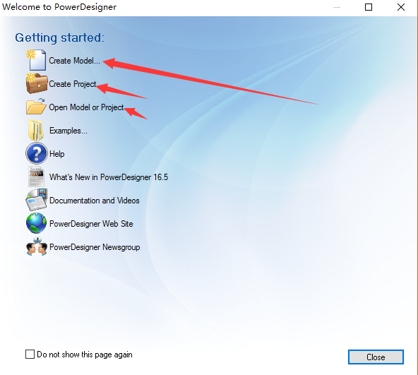
2: Сначала создайте концептуальную модель данных, как показано на рисунке (позже представьте некоторые, такие как физическая модель данных и т. Д., Поскольку все это программное обеспечение на английском языке, так как китайский язык не очень понятен, просто используйте его несколько раз, просто отлично. )
Пожалуйста, сделайте для себя
Концептуальная модель (Концептуальная модель данных МЧР)
Физическая модель (PDM, Физическая модель данных)
Объектно-ориентированная модель (OOM Objcet Oriented Model)
Бизнес-модель (BPM Business Process Model)
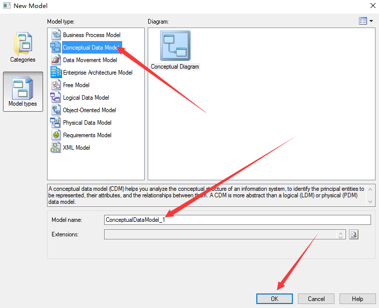
3: Нажмите «ОК» выше, и в левой части рисунка ниже появится концептуальная модель 1. Название концептуальной модели, которой вы владеете. Наиболее часто используются две сущности (сущности) и отношения (отношения), как показано на рисунке.
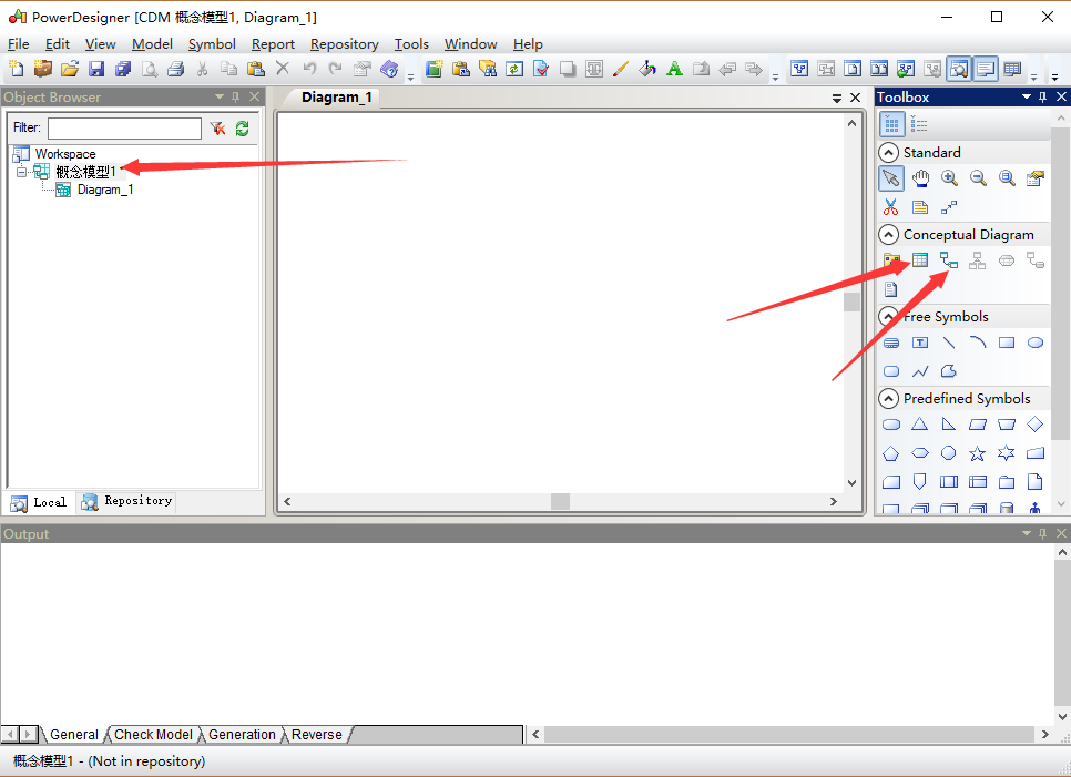
4. Выберите функцию Entity в правом окне, и появится следующее окно. (Следует отметить, что при написании имени код завершается сам. Имя может быть на английском или китайском, но код должен быть на английском. .)
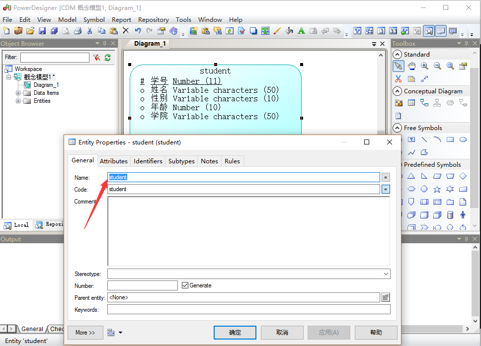
5: После того, как имя и код в общем заполнены, вы можете нажать Атрибуты, чтобы задать имя, код (имя поля в базе данных), Тип данных (тип данных), длину (длина типа данных)
Пожалуйста, сделайте для себя
Имя: имя объекта, как правило, китайское, например, форумчане.
Код: код сущности, обычно на английском языке, например, XXXUser
Комментарий: подробное объяснение этой сущности.
Код атрибута code обычно использует английский UID DataType
Поле «Домен» указывает диапазон значений атрибута, например, можно создать 10-символьное поле адреса.
M: обязательный обязательный атрибут, указывающий, что атрибут обязателен. Не может быть пустым
P: является первичным идентификатором первичным идентификатором, указывающим уникальный идентификатор для физического хранилища
D: отображается отображается, все отмечены по умолчанию
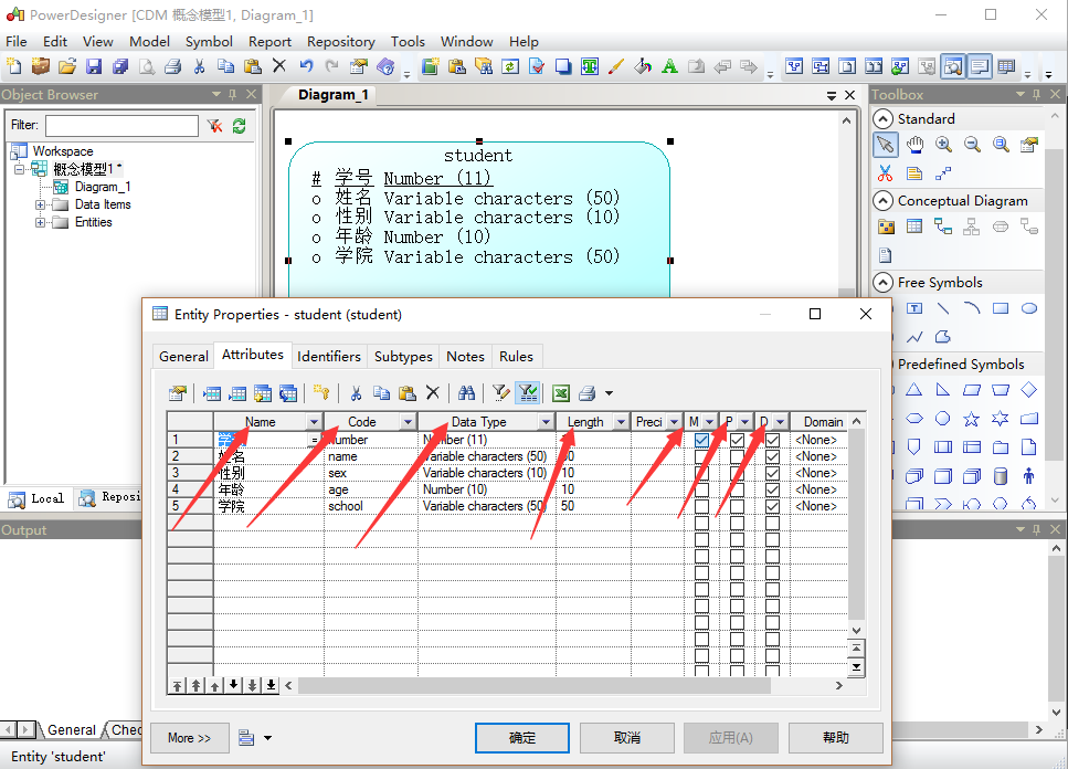
(На этом рисунке объясняется метод именования имени и кода)
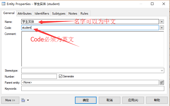
6: Заданный основной идентификатор можно удалить или добавить в модуле «Идентификаторы (идентификатор)».
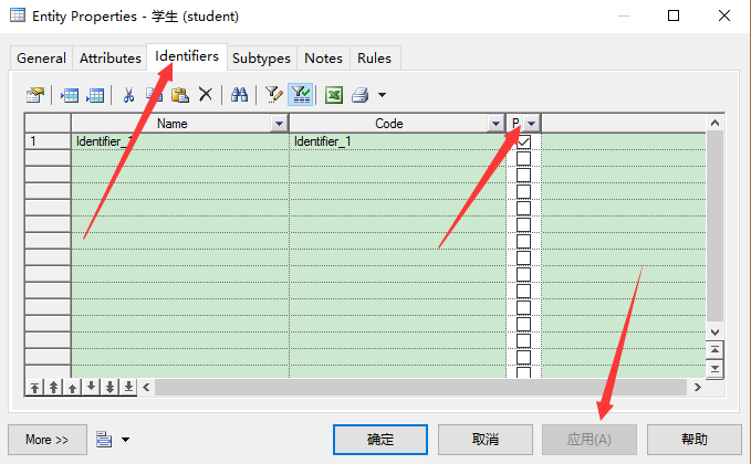
7. Создайте концептуальную модель данных, как показано на рисунке, но созданный шрифт очень маленький, читатель может нажать клавишу ctrl и сдвинуть ползунок мыши, чтобы увеличить сокращенный шрифт, и вы также можете увидеть, что основной идентификатор имеет Также отображается знак числа и видимые атрибуты имени, типа данных и длины
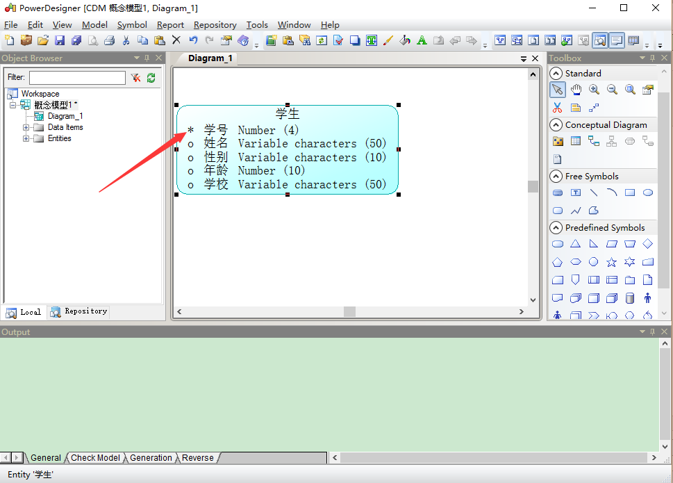
8: Создайте сущность класса таким же образом (Следует отметить, что после нажатия кнопки справа, вам нужно нажать кнопку в состоянии указателя мыши или щелкнуть правой кнопкой мыши. В противном случае легко испортить операцию. Просто обратите внимание на этот момент. ), А затем используйте кнопку Отношения, чтобы связать отношения между учеником и классом, возникает отношение один-ко-многим (класс-ученик) или много-к-одному (ученик-класс). как показано на рисунке
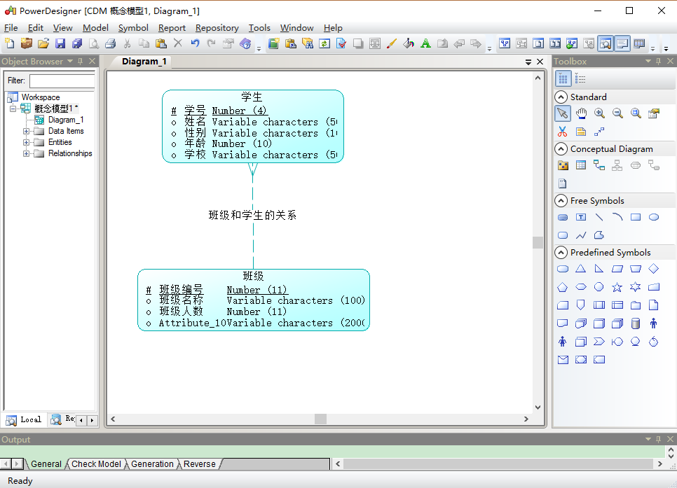
(Следует отметить, что нажатие кнопки «Связь» свяжет класс со студентами, который представляет собой строку, а затем дважды щелкните строку для редактирования, а также имя и код в разделе «Общие»).
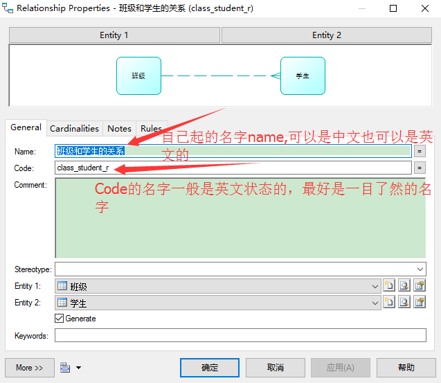
(После того, как вышеприведенные имя и код будут готовы, вы можете проверить отношения между классом и учащимися в разделе «Мощность». Вы можете видеть, что один конец класса — это строка, а другой конец — три, что представляет отношение один-ко-многим между классом и студентом. Для связи многих нажмите Применить, затем подтвердите)
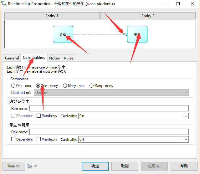
9: упражнения один-ко-многим и многие-к-одному, упражнений много-много, как показано в следующей операции (когда вы обнаружите, что вы использовали этот инструмент очень умело после нескольких операций, это здорово), учитель Сущность такая же, как описано выше, вы можете изменить имя, тип данных и т. Д. В соответствии со своими потребностями в соответствии с потребностями разработки проекта. (Комментарий — это объяснение, вы можете написать соответствующие введения и инструкции)
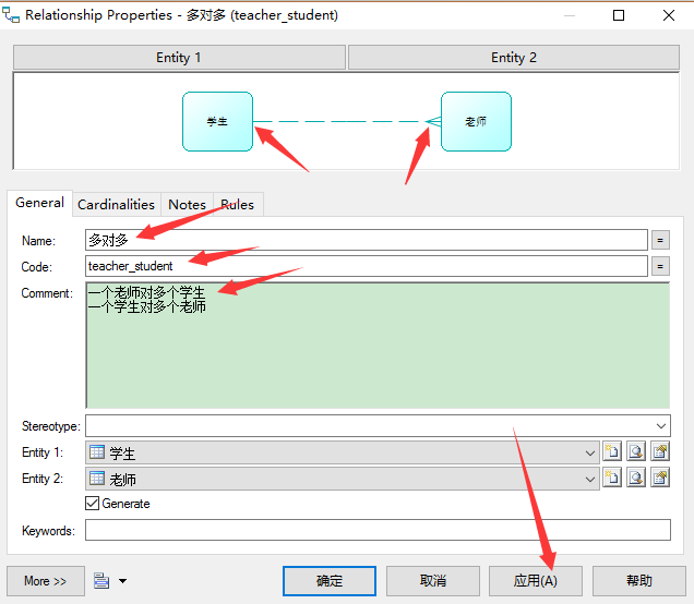
(Когда вам нужно обратить внимание на многие-ко-многим, вы можете вручную нажать кнопку, чтобы настроить отношение как отношение многих ко многим. Отношение многие-ко-многим, а затем нажмите Применить и ОК)

Таким образом, простейшая схема концептуальной модели данных для учащихся, классов и учителей должна учитывать, являются ли тип данных и основной идентификационный код пустыми. Независимо от того, являются ли отношения один-к-одному, один-ко-многим или многие-ко-многим, вам нужно спланировать и затем спроектировать, и тогда у вас все в порядке.
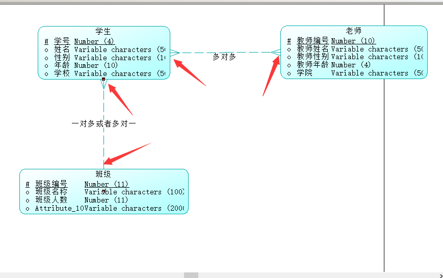
Выше приведена концептуальная модель данных. Физическая модель данных представлена ниже. Физическая модель данных часто используется в будущем.
1. Откройте PowerDesigner, затем выберите «Файл» -> «Новая модель» и выберите физическую модель данных, как показано ниже.
(Имя физической модели данных зависит от вас, и затем вы можете выбрать базу данных, которую вы используете)
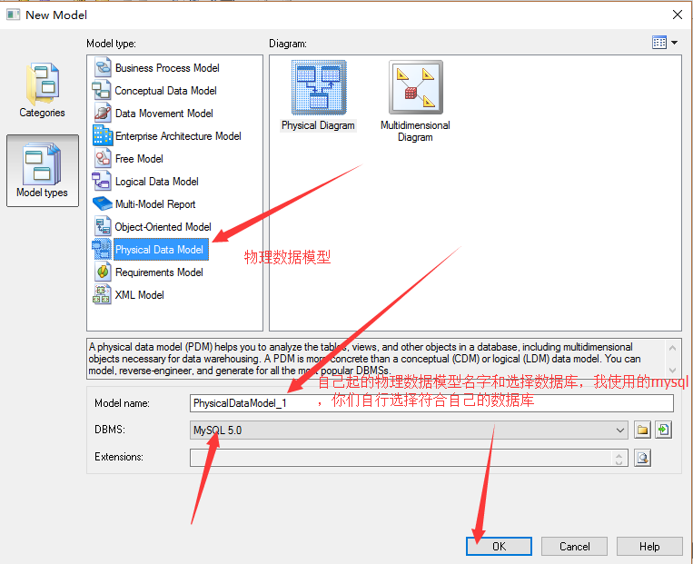
(Главная страница создается, как показано на рисунке, но кнопки справа немного отличаются от концептуальной модели. Три наиболее часто используемые физические модели: таблица (таблица), представление (представление), ссылка (связь));
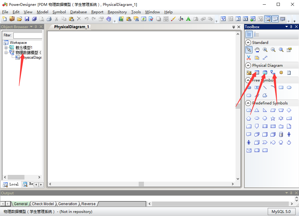
(Сначала щелкните мышью на кнопке таблицы справа, а затем на вновь созданной физической модели, чтобы создать новую таблицу, затем дважды щелкните мышью, чтобы создать новую таблицу, как показано ниже, введите имя и код нужного вам кода, нажмите Применить) следующим образом. Рисунок:
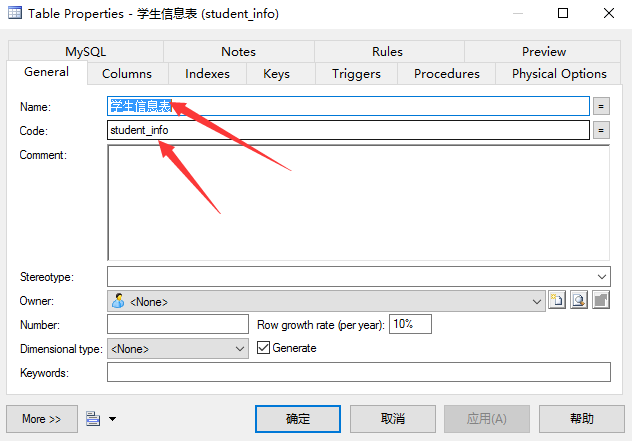
(Затем нажмите на столбцы, установите, как показано на рисунке ниже, серый часто прост, необходимо обратить внимание на P (первичный первичный ключ), F (внешний ключ внешнего ключа), M (обязательный обязательный, представитель не может быть пустым). Эти три, выглядят более Понять его значение.)
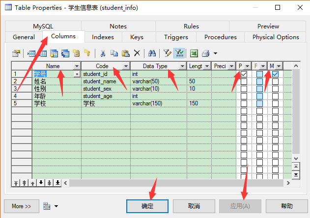
(Установите приращение номера студента здесь (приращение MYSQL — это AUTO_INCREMENT), номер класса такой же, не слишком затягивайте!)
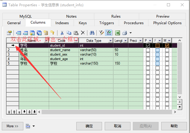
(Вы можете просто проверить число в следующей точке и настроить автоинкремент)
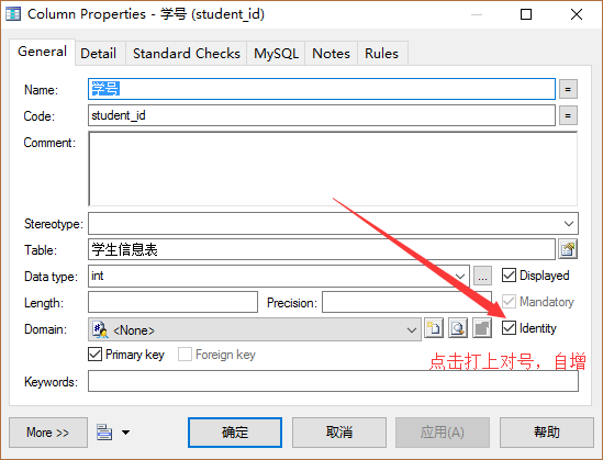
(Как показано на рисунке ниже после завершения.)
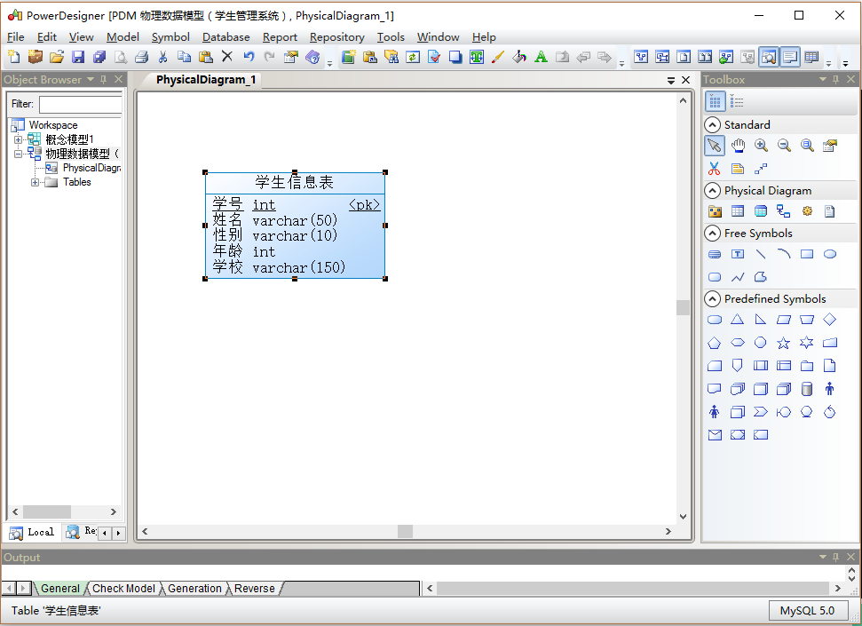
(Физическая модель класса создается аналогично, как показано ниже)
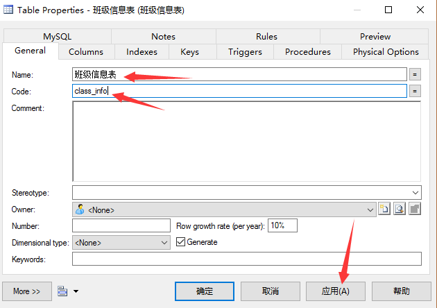
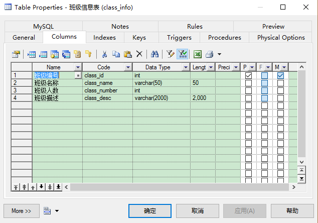
(Как показано на рисунке ниже после завершения)
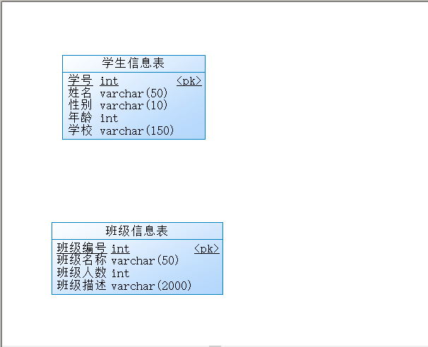
Вышеуказанные настройки соответствуют показанным на рисунке выше, а затем ключевое место занимает следующее: нажмите кнопку на правой кнопке «Справка». Так как класс для учеников один ко многим, значит, мышь перетаскивают из ученика в класс. Как показано на следующем рисунке, таблица ученика появится Изменения, строка добавляется в таблицу учеников, эта строка является первичным ключом таблицы классов в качестве внешнего ключа таблицы учеников, связывая таблицу классов и таблицу учеников. (Посмотрите внимательно, чтобы увидеть разницу.)
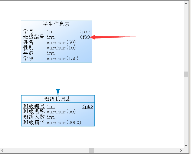
(После выполнения описанной выше операции вы можете дважды щелкнуть строку в середине, чтобы отобразить следующий рисунок, и изменить имя и код).
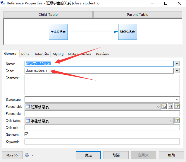
(Тем не менее, следует отметить, что результат, отображаемый после модификации, показан на следующем рисунке. Невозможно напрямую отобразить его в средней строке после модификации в качестве концептуальной модели. Читатель может понять это сам или использовать другой Кнопки также могут добавлять свои собственные комментарии. Например, кнопка «Текст» также может быть добавлена для удобства чтения)

(Изучил отношение «многие к одному» или «один ко многим», а затем изучил отношение «многие ко многим». Точно так же я построил таблицу учителя самостоятельно. Она здесь не описана. Помните, что число учителя увеличивается и строится, как показано на рисунке ниже)
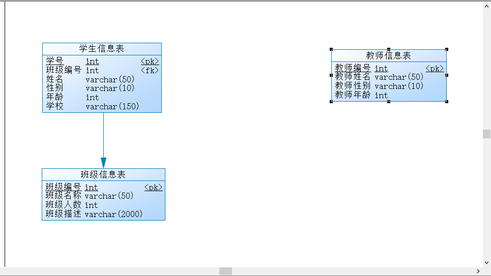
(Следующее является ключом для отношения «многие ко многим», потому что для физической модели отношения «многие ко многим» для соединения требуется промежуточная таблица, как показано на следующем рисунке, установлено только одно поле, первичный ключ, самоинкремент).
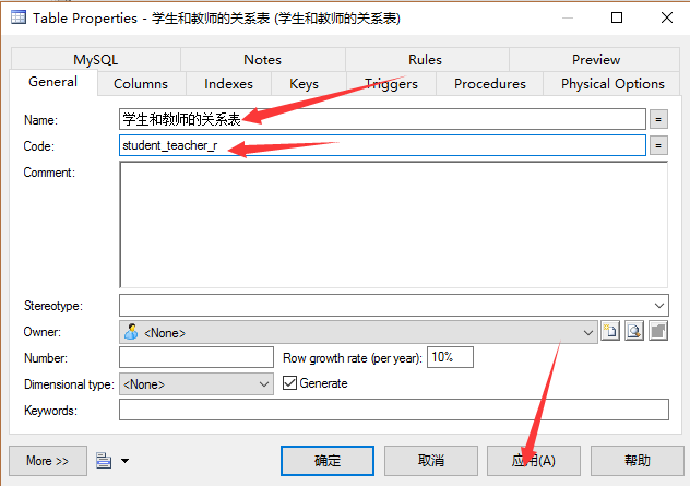
(Нажмите «Применить», затем установите «Столбцы», добавьте только одно поле).
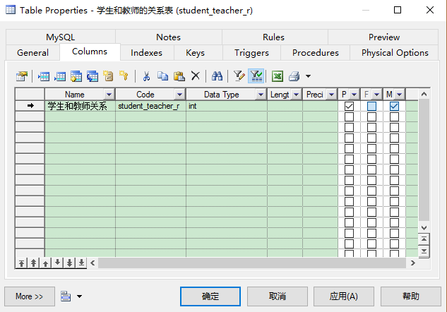
(Это увеличивает поле настройки, которое было описано несколько раз ранее)
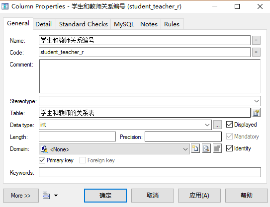
(После установки, как показано ниже) (Следует отметить, что сторона со стрелками — одна, сторона без стрелок — больше, то есть необходимо понимать отношение один-ко-многим к одному, и у учащихся также может быть много учителей, учителей. Студентов и учителей может быть много, поэтому основной частью могут быть студенты и учителя, то есть мужчины / женщины.
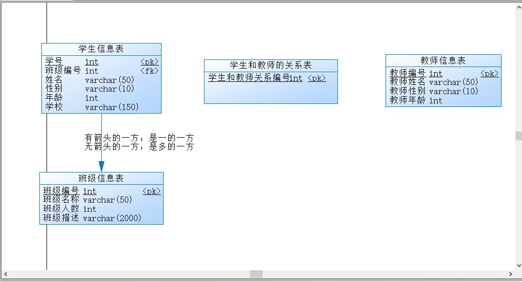
(Вы можете увидеть изменения до и после таблицы отношений между учениками и учителями после добавления отношений)
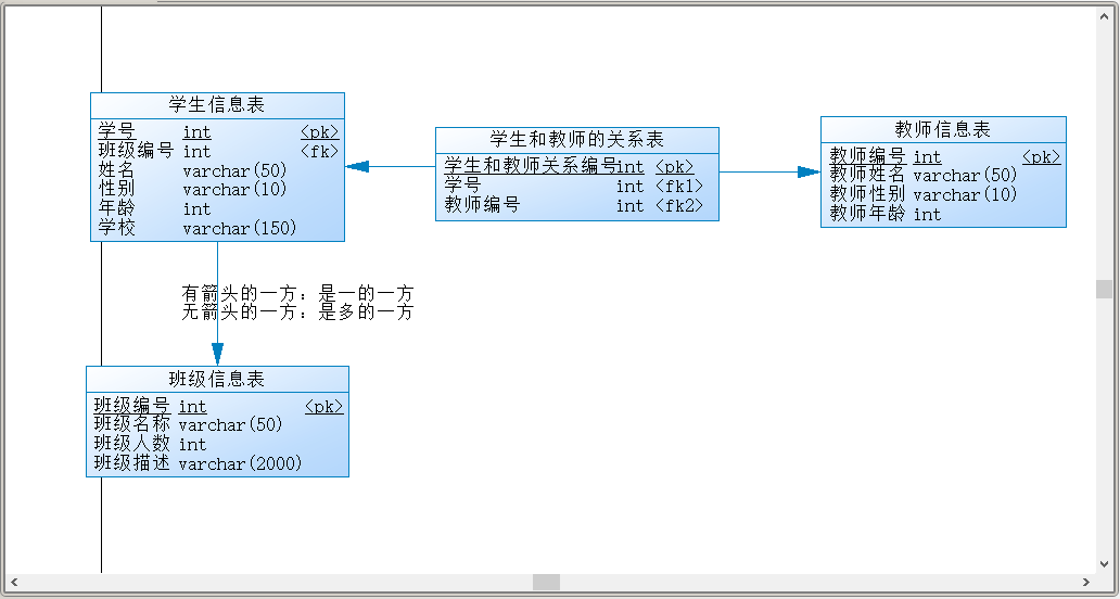
(Для подробных знаний или связанных с базой данных, пожалуйста, создайте свой собственный мозг. Здесь я расскажу, как правильно использовать инструмент PowerDesigner)
Далее будут представлены концептуальная модель в физической модели и физическая модель в концептуальной модели
1. Откройте диаграмму концептуальной модели, как показано на рисунке ниже, затем нажмите «Инструмент», как показано на рисунке ниже.
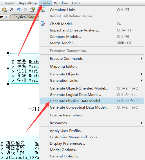
(Открытая страница показана ниже. Я изменил название и код с концептуальной модели 1 на физическую модель 1)
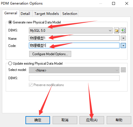
(После завершения, как показано на рисунке ниже, измененная физическая модель будет открыта сама по себе. Следует отметить, что тип данных этих таблиц изменился сам по себе, и в средней таблице есть два первичных ключа, то есть двойной первичный ключ.)
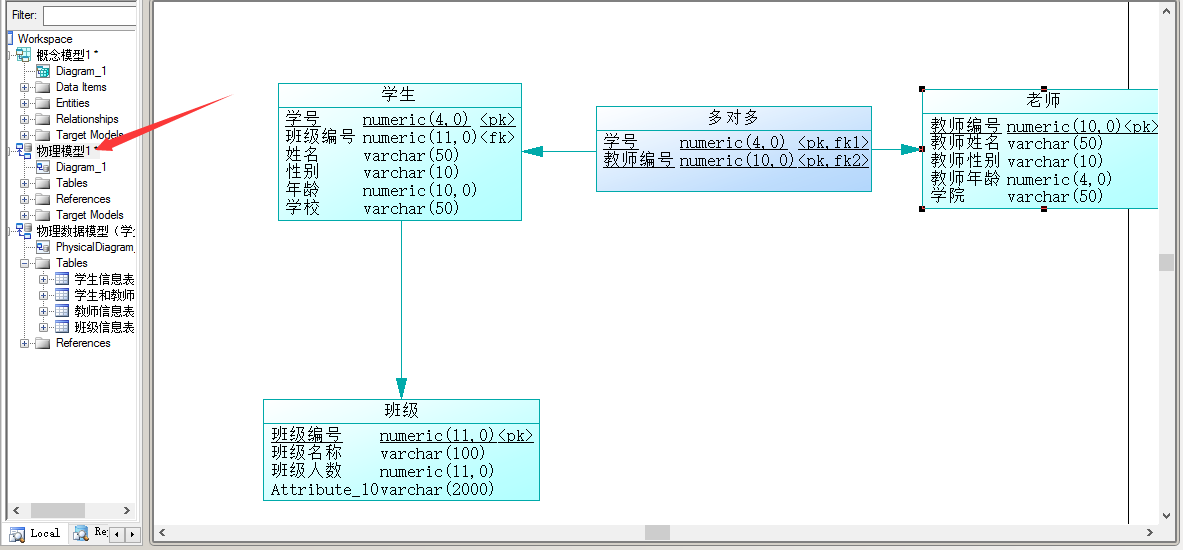
(Создайте мозг здесь, потому что я щелкнул вокруг и щелкнул ToolBox справа. Я сказал это здесь, это ToolBox в меню представления, нажмите, чтобы открыть)
(Поскольку я пользуюсь компьютером и автоматически выключаюсь, я также пьян, снова откройте PowerDesigner, как показано ниже, самостоятельно щелкните правой кнопкой мыши на открытии.)
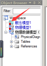
1: Выше описывается преобразование концептуальной модели в физическую модель, а следующее представляет преобразование физической модели в концептуальную модель (щелкните операцию, как показано ниже)
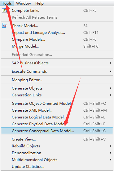
(Затем появится интерфейс, показанный на рисунке ниже, и затем измените физику в соответствии с концепцией, нажмите на приложение, чтобы подтвердить и распознать)
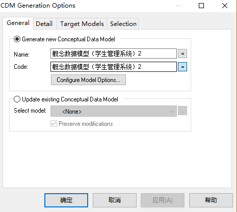
(После нажатия кнопки «Подтвердить» откроется страница, как показано на рисунке ниже, и вы увидите, что изменилось. Если она преобразуется в oracle, тип данных изменится, например, Varchar2 и т. Д.);
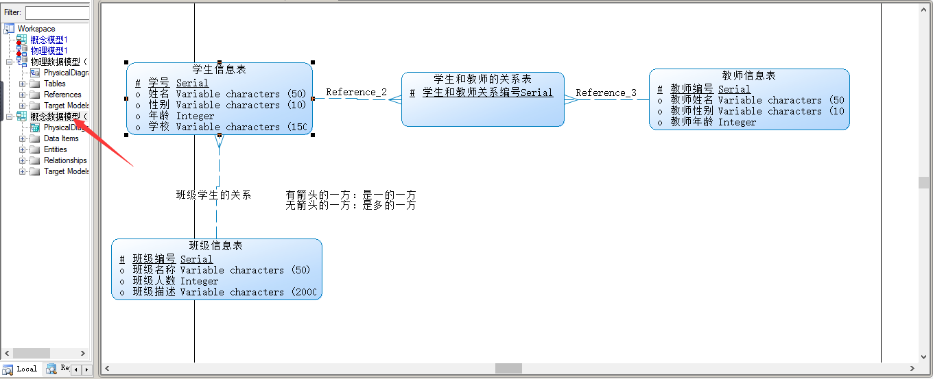
1: Ниже представлен оператор SQL для экспорта физической модели (нажмите кнопку База данных Создать базу данных или нажмите Ctrl + G)
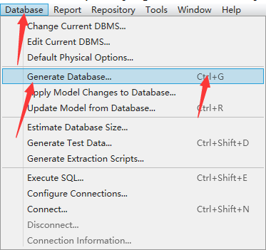
(После открытия, как показано на рисунке, измените местоположение, где существует оператор SQL, и имя сгенерированного файла.)
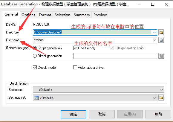
(Выберите таблицу для экспорта в программе «Выделение», а затем нажмите «Применить и подтвердить»).
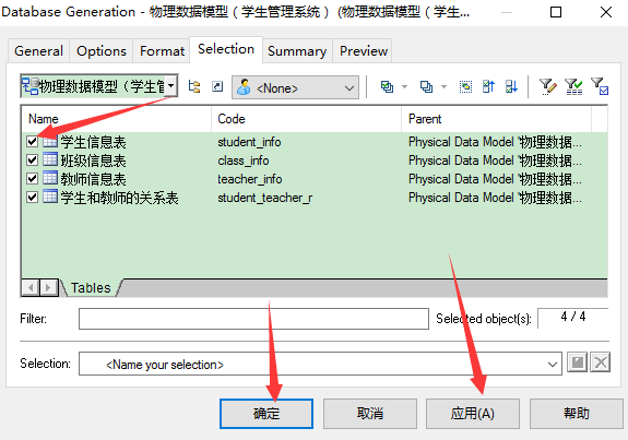
(После завершения, как показано ниже, вы можете нажать кнопку Изменить или закрыть)
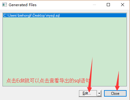
(С тех пор вы завершили экспорт оператора SQL, вы можете перейти в указанное вами местоположение, чтобы просмотреть экспортированный оператор SQL;)
ФЕДЕРАЛЬНОЕ АГЕНСТВО ПО ОБРАЗОВАНИЮ ГОСУДАРСТВЕННОЕ ОБРАЗОВАТЕЛЬНОЕ УЧРЕЖДЕНИЕ ВЫСШЕГО ПРОФЕССИОНАЛЬНОГО ОБРАЗОВАНИЯ
РЯЗАНСКИЙ ГОСУДАРСТВЕННЫЙ РАДИОТЕХНИЧЕСКИЙ УНИВЕРСИТЕТ
Автоматизация проектирования баз данных в среде
Sybase PowerDesigner
Методические указания к лабораторным работам
Рязань 2010
УДК 004.655.3 (078.8)
Автоматизация проектирования баз данных в среде Sybase PowerDesigner: Методические указания к лабораторным работам. / Рязан. гос. радиотехн. универ.; Сост. А.В. Благодаров, Р.В. Тишкин,
Рязань, 2010. 35 с.
Содержат рекомендации для проведения лабораторных работ, посвященных изучению CASE-средства проектирования баз данных
Sybase PowerDesigner.
Предназначены для студентов очной и заочной форм обучения специальностей 230101 «Вычислительные машины, комплексы, системы и сети», 230104 «Системы автоматизированного проектирования», 230105 «Программное обеспечение вычислительной техники и автоматизированных систем», 080801 «Прикладная информатика», по дисциплинам «Базы данных», «Проектирование баз данных», «Клиент-серверные приложения баз данных».
Автоматизация проектирования баз данных в среде Sybase PowerDesigner
Составитель
Бл а г о д а р о в Андрей Витальевич
Ти ш к и н Роман Валентинович
1
Цель работы: Получить навыки проектирования реляционных баз данных с помощью программы Sybase PowerDesigner 15.
Основные возможности программы PowerDesigner
Программа Sybase PowerDesigner 15 представляет собой CASEсредство для проектирования баз данных и программных систем в целом. Термин CASE (Computer Aided Software Engineering) означает автоматизированное проектирование программного обеспечения, в данном случае баз данных. Использование PowerDesigner существенно сокращает время, затрачиваемое на проектирование БД.
PowerDesigner позволяет автоматизировать практически все этапы проектирования не только базы данных, но всей информационной системы в целом. В рамках лабораторной работы рассмотрим лишь малую часть возможностей, предоставляемых программой, интересную с точки зрения проектирования реляционных баз данных. К этим возможностям можно отнести:
•создание концептуальной модели БД;
•создание логической модели БД;
•создание физической модели БД;
•автоматическая генерация SQL-скрипта для создания структуры БД;
•обратное проектирование БД.
Концептуальная модель (CDM – Conceptual Data Model)
позволяет представить структуру БД в наиболее абстрактном виде. В рамках данной модели можно задавать сущности, их атрибуты и связи между сущностями.
Логическая модель (LDM – Logical Data Model) позволяет представить структуру БД в несколько менее абстрактном виде, чем CDM. В частности, в сущности добавляются атрибуты внешних ключей для связей c другими сущностями. LDM, как и CDM, совершенно не зависит от СУБД, на которой в дальнейшем будет реализовываться БД.
Физическая модель (PDM – Physical Data Model) позволяет представить структуру БД с учетом особенностей выбранной СУБД. Сущности заменяются таблицами, для некоторых связей также создаются таблицы. Можно задать необходимые частные ограничения
2
целостности. Для одной LDM можно создать произвольное число независимых PDM под разные СУБД.
Полная независимость концептуальной и логической моделей от конкретной СУБД и возможность создания произвольного числа физических моделей для разных СУБД является важным достоинством программы PowerDesigner.
К другим полезным возможностям программы по автоматизации процесса проектирования БД, не рассмотренным в данной работе, можно отнести:
•создание моделей многомерных БД;
•создание XML–моделей.
Порядок проектирования базы данных
Процесс проектирования БД с помощью программы PowerDesigner может выглядеть следующим образом.
1.Создание проекта для разрабатываемой БД.
2.Создание концептуальной модели (CDM), в которой указываются выявленные сущности, их ключи и связи между ними.
3.Создание логической модели (LDM), которая генерируется на основе CDM. В LDM для каждой сущности указывают неключевые атрибуты, задают их типы, указывают признаки обязательности атрибута. Для каждой сущности выполняют проверку на соответствие нормальным формам. При необходимости выполняют декомпозицию сущностей.
4.Создание физической модели (PDM), которая генерируется на основе LDM. При генерации PDM выбирается определенная СУБД, особенности которой учитываются при создании физической модели. Для полей таблиц при необходимости уточняются типы данных. Указываются частные ограничения целостности.
5.Генерация SQL-скрипта для создания структуры БД. Полученный скрипт можно исполнить средствами СУБД и получить готовую БД.
Будем рассматривать процесс проектирования БД на следующем примере. Пусть требуется спроектировать БД для хранения информации об учебном процессе в вузе. Краткое неформальное описание предметной области приведено ниже.
Занятия в вузе проводятся по заданному расписанию. Занятие проводится в определенной учебной группе, в некоторой аудитории, одним преподавателем, по некоторой дисциплине и занимает одну пару. Каждая группа обучается по определенной специальности. Для специальностей определены списки читаемых дисциплин.
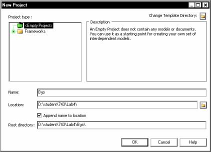
3
Специальность относится к определенному факультету. Преподаватель работает на одной кафедре. Кафедры бывают выпускающими и общими. Выпускающая кафедра может выпускать несколько специальностей Общая кафедра специальности не выпускает, но может относиться к определенному факультету.
С помощью БД необходимо иметь возможность получать информацию о:
•расписании занятий;
•списках учебных групп, их специальностях и выпускающих кафедрах;
•списках дисциплин для заданной специальности;
•списках преподавателей по заданной кафедре;
•списках групп по факультетам;
•списках кафедр по факультетам.
Создание проекта
Создадим новый проект, выполнив пункт главного меню File– New Project. (рисунок 1). Укажем имя проекта, например «Вуз», и путь к папке проекта.
Рисунок 1 – Создание нового проекта
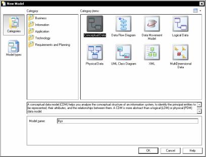
4
Сохраним проект, выполнив пункт меню File–Save All. Проект сохраняется в файле с расширением *.prj.
Создание концептуальной модели
Создадим концептуальную модель, выполнив пункт главного меню File–New Model. В открывшемся окне (рисунок 2) выберем значок ConceptualData и зададим имя модели, например «Вуз».
Рисунок 2 – Создание новой концептуальной модели
Сохраните модель, выполнив пункт меню File–Save All. Концептуальная модель сохранится в файле с расширением *.cdm.
Выполним некоторые необходимые настройки программы PowerDesigner. Зайдем в пункт меню Tools–Model Options (рисунок 3). Выберем тип нотации (Notation) Entity/Relationship. Данная нотация известна как Crow Foot (воронья лапа). При необходимости можно использовать и другие нотации, например: IDEF1X или Barker. Разрешим использование атрибутов с одинаковыми именами в разных сущностях, сняв флажок Data Item – Unique code. Если этого не сделать, то не удастся, например, атрибут ID использовать в двух разных сущностях.
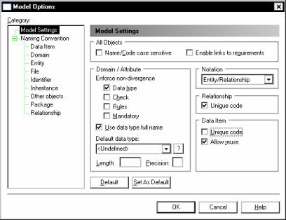
5
Рисунок 3 – Настройка концептуальной модели
Зайдем в пункт меню Tool – Display Preferences (настройки отображения). Выберем категорию Content – Relationship (связи) и установим флажок Cardinality, чтобы на диаграмме отображалась кардинальность связи (0,1; 1,1; 0,n или 1,n).
В категории Content – Entity (сущности) уберем флажок Identifiers (рисунок 4), чтобы не отображались идентификаторы сущностей (на наш взгляд, идентификаторы сущностей излишни, достаточно показать ключ). Зададим отображение только ключевых атрибутов
(Attributes–Primary attributes). Уберем отображение типов данных
(Data types), признака обязательности атрибута (Mandatory).
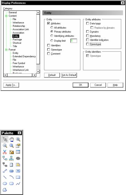
6
Рисунок 4 – Настройка отображения сущностей концептуальной модели
Смысл перечисленных настроек сводится к тому, чтобы отображались только сущности с ключами и связи. Остальная более детальная информация, в частности, не ключевые атрибуты на этапе разработки концептуальной модели не нужна.
Нарисуем ER-диаграмму для нашей БД.
Сначала создадим все сущности. Чтобы создать сущность, выберем в окошке Палитра (Palette) кнопку Entity  и разместим сущность в требуемом месте области модели. Чтобы отобразить палитру следует выполнить действие Tools – Customize Toolbars и
установить флажок для пункта Palette.
Для сущности зададим имя и ключ. Для этого сделаем двойной щелчок по сущности или выполним для сущности пункт контекстного меню Properties (свойства).
В открывшемся окне (рисунок 5) зададим поля Name (имя сущности) и Code (имя сущности в коде). Различие просто имени и имени в коде заключается в том, что просто имя будет отображаться лишь на
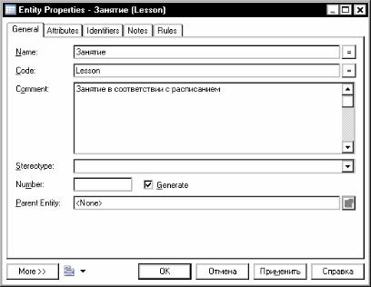
7
диаграммах, а имя в коде будет использоваться в дальнейшем в SQLскрипте для создания таблицы БД. Просто имя пишут обычно на русском языке и делают максимально понятным для человека, а имя в коде обычно пишут латинскими буквами без пробелов и спецсимволов так, чтобы достичь максимальной совместимости с любой СУБД. При желании, конечно, можно сделать эти два поля одинаковыми. Для этого удобно использовать кнопки = справа от поля. Также зададим комментарий к сущности (поле Comment), который в дальнейшем может быть добавлен в SQL-скрипт. Например, зададим просто название сущности Занятие, и название в коде Lesson.
Рисунок 5 – Задание имени сущности
Затем перейдем на вкладку Attributes (атрибуты), представленную на рисунке 6. Настроим список отображаемых
сведений об атрибуте, нажав кнопку  (Customize Columns and Filter). Выберем отображение лишь следующих данных:
•Name – имя атрибута;
•Code – имя атрибута в коде;
•Comment – комментарий;
•Data Type – тип данных;

8
•Primary Identifier – ключ;
•Displayed – отображаемое поле.
Рисунок 6 – Задание ключа сущности
Имя атрибута и имя атрибута в коде соотносятся так же, как и понятия «просто имя» и «имя в коде» для сущности. Настройка выполняется только один раз.
Зададим ключ сущности, создав новый атрибут, например, с именем ID, и задав ему свойство P (Primary Identifier ), а также выбрав подходящий тип данных, например Serial (счетчик). В результате получим следующее изображение сущности (рисунок 7).
Рисунок 7 – Изображение сущности
Аналогичным образом создадим все остальные сущности и их ключи, как показано в таблице 1.
![]()
9
|
Таблица 1 |
||||
|
Сущность |
Ключ |
|||
|
Name |
Code |
Name |
Code |
|
|
Выпускающая |
ChairGraduation |
|||
|
кафедра |
||||
|
Группа |
Groups |
Номер |
N |
|
|
Дисциплина |
Subject |
Шифр |
Code |
|
|
Занятие |
Lesson |
ID |
ID |
|
|
Кафедра |
Chair |
Краткое |
NameShort |
|
|
название |
||||
|
Общая кафедра |
ChairGeneral |
|||
|
Пара |
Pare |
Номер |
N |
|
|
Преподаватель |
Teacher |
Табельный |
TN |
|
|
номер |
||||
|
Специальность |
Speciality |
Шифр |
Code |
|
|
Факультет |
Department |
Краткое |
NameShort |
|
|
название |
Обратите внимание, что для сущностей Выпускающая кафедра и Общая кафедра ключи пока не задаются, так как они будут сформированы автоматически несколько позже.
Зададим связи между сущностями. Для этого выберем на палитре
инструмент  – Relationship (связь). С помощью мыши проведем связь от главной сущности к подчиненной. Главной будем считать ту, которая связана к одному, а подчиненной – ко многим. Для связи многие ко многим направление, в котором проводится связь, не имеет значения. Например, проведем связь между сущностями Кафедра и Преподаватель. На одной кафедре может работать много преподавателей, преподаватель может работать не более, чем на одной кафедре. Получается связь, показанная на рисунке 8.
Рисунок 8 – Пример связи
Зададим характеристики связи. Для этого выполним двойной щелчок мыши по связи или выполним для нее пункт Properties (свойства) контекстного меню.
В открывшемся окне (рисунок 9) зададим имя связи (Name) и имя связи в коде (Code). Имя связи обычно задают в виде глагола или предлога, а имя связи в коде – в виде имен в кодах двух связываемых сущностей. В нашем примере это будет Работает и TeacherChair. Комментарий к связям обычно не пишут.

10
Рисунок 9 – Задание имени связи
Теперь перейдем на вкладку Cardinalities (кардинальность), изображенную на рисунке 10. Здесь задаются основные характеристики связи, к каковым относят следующее.
1.Степень связи, которая бывает: один к одному (One – One); один ко многим (One – Many); многие к одному (Many – One); многие ко многим (Many – Many).
2.Доминантная сущность (Dominant role) (только для связи один к одному). Показывает, какая из двух сущностей является главной (доминантной). В оставшейся подчиненной сущности в дальнейшем будет создан внешний ключ.
3.Обязательность связи (Mandatory) показывает, обязательно ли каждый экземпляр сущности должен участвовать хотя бы в одной связи.
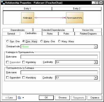
11
4.Зависимость (Dependent), является ли связь с данной сущностью идентифицирующей. Если признак установлен, то в дальнейшем внешний ключ сущности будет входить в состав ключа этой же сущности.
5.Кардинальность связи для каждого из двух направлений связи. Кардинальность A to B показывает, со сколькими экземплярами
сущности B может быть связан один экземпляр сущности A. Различают кардинальности: 0..1, 1..1, 0..n, 1..n. Например, кардинальность Преподаватель – Кафедра будет 0..1 (преподаватель может работать не более чем на одной кафедре). Кардинальность Кафедра – Преподаватель будет 0..n (на кафедре может работать множество преподавателей). Кардинальность зависит от степени и обязательности связи и наоборот.
Рисунок 10 – Задание кардинальности связи
На рисунке 11 приведены примеры обозначений связей с различными степенями связей, и соответственно, различными кардинальностями.
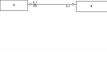
12
а)
б)
в)
г)
Рисунок 11 – Обозначения связей
На рисунке 11-а изображена связь один ко многим, на которой экземпляр сущности A может быть связан с несколькими экземплярами сущности B. Экземпляр сущности B обязательно связан с одним и только одним экземпляров сущности A.
На рисунке 11-б изображена связь один ко многим, на которой экземпляр сущности A может быть связан с несколькими экземплярами сущности B. Экземпляр сущности B может связан не более чем с одним экземпляров сущности A.
На рисунке 11-в изображена связь многие ко многим, на которой экземпляр сущности A может быть связан с несколькими экземплярами сущности B. Экземпляр сущности B может связан с несколькими экземплярами сущности A.
На рисунке 11-г изображена связь один к одному, на которой экземпляр сущности A может быть связан не более, чем с одним экземплярам сущности B. Экземпляр сущности B может быть связан не более, чем с одним экземплярам сущности A. Сущность А является доминантной.
Для реализации ролевых и обобщающих сущностей в PowerDesigner используется понятие наследования (Inheritance). В рамках наследования выделяется одна родительская сущность (Parent entity), являющаяся аналогом обобщающей сущности, и множество

13
дочерних сущностей (Child entity), являющиеся аналогом ролевых сущностей. Родительская сущность содержит общий набор атрибутов,
адочерние сущности – частные наборы атрибутов.
Внашем примере можно выделить родительскую сущность
Кафедра и две дочерние сущности: Выпускающая кафедра и Общая кафедра.
Для реализации наследования выберем на палитре инструмент
 – Inheritance. С помощи мыши соединим дочернюю сущность Выпускающая кафедра с родительской сущностью Кафедра. Затем соединим вторую дочернюю сущность Общая кафедра с символом
наследования  . Зайдя в свойства символа наследования, зададим имя наследования, которое обычно совпадает с именем родительской сущности. Полученный фрагмент диаграммы изображен на рисунке
12.
Рисунок 12 – Пример наследования Различают следующие виды наследования.
1.Обычное наследование. Обозначается символом 
2.Взаимоисключающее наследование (Mutually exclusive inheritance). При таком наследовании экземпляр родительской сущности может быть связан с экземпляром только одной дочерней
сущности. Обозначается символом  . На физическом уровне такое наследование обычно реализуется путем добавления специальных триггеров к таблицам дочерних сущностей. К сожалению, автоматическая генерация таких триггеров в PowerDesigner не предусмотрена, это придется сделать своими руками.
3. Законченное наследование (Complete inheritance). При таком наследовании экземпляр родительской сущности обязательно должен быть связан с экземпляром некоторой дочерней сущности. На физическом уровне такое наследование реализуется путем
использования механизма транзакций. Обозначается символом 
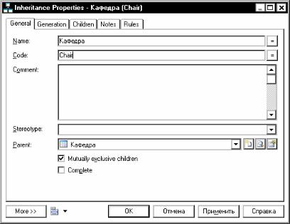
14
4. Взаимоисключающее законченное наследование. Является
комбинацией видов 2 и 3. Обозначается символом  .
.
Вид наследование задается на вкладке General свойств наследования (рисунок 13).
Рисунок 13 – Выбор вида наследования
Для нашего примера выберем взаимоисключающее законченное наследование, так как кафедра может быть либо выпускающей, либо общей.
На вкладке Generation необходимо задать особенности генерации сущностей при переходе к логической или физической модели. Установим флажки Generate parent (генерировать родительскую сущность) и Generate child (генерировать дочерние сущности), а также выберем радио-кнопку Inherit only primary attributes (наследовать только ключевые атрибуты), как показано на рисунке 14.
При таких настройках в логической модели в дальнейшем будут созданы и родительская и дочерние сущности, а ключ родительской сущности появится в качестве первичного и внешнего ключа в дочерних сущностях. Поэтому мы и не задавали ранее ключи в дочерних сущностях Выпускающая кафедра и Общая кафедра.
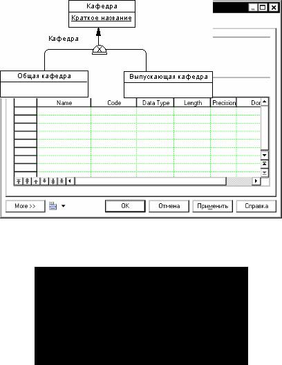
15
Рисунок 14 – Выбор вида наследования
На рисунке 15 показан фрагмент диаграммы после настройки наследования.
Рисунок 15 – Пример наследования
Создадим все остальные связи между сущностями, как показано на рисунке 16, тем самым получим готовую CDM.
Соседние файлы в предмете [НЕСОРТИРОВАННОЕ]
- #
- #
- #
- #
- #
- #
- #
- #
- #
- #
- #