+7 (863) 210-11-44
Покупай как юр. лицо
ЖурналАкцииКонфигураторДоставкаМагазиныОбратная связь
Каталог товаров
Войти
Избранное
Сравнение
Корзина
Строительство и ремонт
Измерительная техника
Измерительный инструмент
UNI-T
5
1
Отзыв
Код товара: 1636168
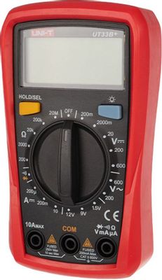
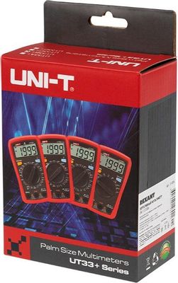


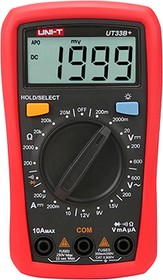
Мультиметр UNI-T UT33B+ [13-0056]
Код товара: 1636168
1 290₽
1 260 для членов клуба Ситилинк
- Измерение напряжения: до 600 В;
- Измерение тока: постоянного, до 10 A;
- Измерение сопротивления: до 20 МОм;
- Размеры (ШxВxГ): 77 x 134 x 47 мм;
Появились вопросы о товаре?

- Измерение напряжения: до 600 В;
- Измерение тока: постоянного, до 10 A;
- Измерение сопротивления: до 20 МОм;
- Размеры (ШxВxГ): 77 x 134 x 47 мм;
Появились вопросы о товаре?
1 290₽
1 260 для членов клуба Ситилинк
1 290₽
1 260 для членов клуба Ситилинк
О товаре
Характеристики
Аксессуары
Услуги5
Обзоры
Отзывы1
Вопрос-ответ
Инструкции и документы5
Хочу быть в курсе акций и новинок
Контакты
Адреса магазинов
+7 (863) 210-11-44
- Журнал
- Акции
- Покупателям
- Информация
- Доставка
- Гарантия
- Кредит и рассрочка
- Сервисные центры
- Услуги
- Корпоративным клиентам
- Аренда помещений
- Партнёрская программа
- Обзоры
- Форум
- Клуб Ситилинк
- Конфигуратор
- Подбор расходных материалов
- Ситилинк
- Новости
- Вакансии
- Документы
© Ситилинк, 2008 – 2023
Политика обработки персональных данных
Мы используем файлы cookie. Подробнее
Мы используем файлы cookie для вашего удобства пользования сайтом и повышения качества рекомендаций. Подробнее
Главная
Каталог
Корзина
Избранное
Сравнение
Войти

- Manuals
- Brands
- UNI-T Manuals
- Multimeter
- UT33B
- Operating manual
-
Contents
-
Table of Contents
-
Bookmarks
Quick Links
Model UT33B/C/D: OPERATING MANUAL
Table of Contents (1)
Title
1
Page
3
4
5
7
10
11
12
13
13
15
17
20
22
25
27
Related Manuals for UNI-T UT33B
Summary of Contents for UNI-T UT33B
-
Page 1: Table Of Contents
Model UT33B/C/D: OPERATING MANUAL Table of Contents (1) Title Page Overview Unpacking Inspection Safety Information Rules For Safe Operation International Electrical Symbols The Meter structure Functional Buttons Measurement Operation DC Voltage Measurement AC Voltage Measurement DC Current Measurement D. Measuring Resistance…
-
Page 2
Model UT33B/C/D: OPERATING MANUAL Table of Contents (2) Title Page Square Wave Output General Specifications Accuracy Specifications DC Voltage AC Current C. DC Current D. Resistance Diodes and Continuity Measurement Temperature G. Battery Test Square Wave Output Maintenance General Service… -
Page 3: Overview
To avoid electric shock or personal injury, read the “Safety Information” and “Rules for Safety Operation” carefully before using the Meter. The Model UT33B, UT33C and UT33D Multimeters (hereafter referred as “the Meter”) are 3 1/2 digits with steady operations, fashionable design and highly reliable hand-held measuring instrument.
-
Page 4: Unpacking Inspection
Model UT33B/C/D: OPERATING MANUAL Unpacking Inspection Open the package case and take out the Meter. Check the following items carefully to see any missing or damaged part: Item Description English Operating Manual 1 piece 1 pair Test Lead 1 piece…
-
Page 5: Safety Information
Model UT33B/C/D: OPERATING MANUAL Safety Information(1) Safety Information This Meter complies with the standards IEC61010: in pollution degree 2, overvoltage category (CAT I 600V, CAT II 300V) and double insulation. CAT. I: Signal level, special equipment or parts of equipment, telecommunication, electronic, etc., with smaller transient overvoltages than overvoltages CAT.
-
Page 6
Model UT33B/C/D: OPERATING MANUAL Safety Information(2) In this manual, a Warning identifies conditions and actions that pose hazards to the user, or may damage the Meter or the equipment under test.A Note identifies the information that user should pay attention on. -
Page 7: Rules For Safe Operation
Model UT33B/C/D: OPERATING MANUAL Rules For Safe Operation (1) Warning To avoid possible electric shock or personal injury, and to avoid possible damage to the Meter or to the equipment under test, adhere to the following rules: l Before using the Meter inspect the case. Do not use the Meter if it is damaged or the case (or part of the case) is removed.
-
Page 8
Model UT33B/C/D: OPERATING MANUAL Rules For Safe Operation (2) prevent damage of the Meter. l When the Meter working at an effective voltage over 60V in DC or 42V rms in AC, special care should be taken for there is danger of electric shock. -
Page 9
Model UT33B/C/D: OPERATING MANUAL Rules For Safe Operation (3) l Remove test leads and temperature probe from the Meter and turn the Meter power off before opening the Meter case. l When servicing the Meter, use only the same model number or identical electrical specifications replacement parts. -
Page 10: International Electrical Symbols
Model UT33B/C/D: OPERATING MANUAL International Electrical Symbols AC or DC AC Current DC Current Earth Ground Double Insulated. Low Battery. Diode. Fuse. Continuity Test Safety Rules Conforms to Standards of European Union.
-
Page 11: The Meter Structure
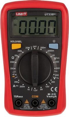
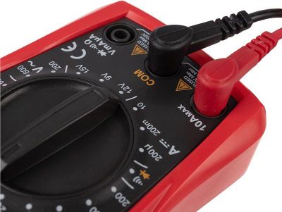
Model UT33B/C/D: OPERATING MANUAL The Meter Structure The Meter Structure (figure 1) LCD Display HOLD Button Display Backlight Button Rotary Switch COM Input Terminal 10A Input Terminal Other Input Terminals (figure 1)
-
Page 12: Functional Buttons
Model UT33B/C/D: OPERATING MANUAL Functional Buttons Below table indicated for information about the functional button operations. Button Operation Performed l Press HOLD once to enter hold mode. HOLD button l Press HOLD again to exit hold mode. l In Hold mode, is displayed and the present value is shown.
-
Page 13: Measurement Operation
Model UT33B/C/D: OPERATING MANUAL Measurement Operation(1) A. DC Voltage Measurement (see figure 2) Warning To avoid harms to you or damages to the Meter from electric shock, please do not attempt to measure voltages higher than 500V although readings may be obtained.
-
Page 14
Model UT33B/C/D: OPERATING MANUAL Measurement Operation (2) Note If the value of voltage to be measured is unknown, use the maximum measurement position (500V) and reduce the range step by step until a satisfactory reading is obtained. The LCD displays “1” indicating the existing selected range is overload; it is required to select a higher range in order to obtain a correct reading. -
Page 15: Ac Voltage Measurement
Model UT33B/C/D: OPERATING MANUAL Measurement Operation (3) AC Voltage Measurement (see figure 2) Warning To avoid harms to you or damages to the Meter from electric shock, please do not attempt to measure voltages higher than 500Vrms although readings may be obtained.
-
Page 16
Model UT33B/C/D: OPERATING MANUAL Measurement Operation (4) Note If the value of voltage to be measured is unknown, use the maximum measurement position (500V) and reduce the range step by step until a satisfactory reading is obtained. The LCD displays “1” indicating the existing selected range is overload, it is required to select a higher range in order to obtain a correct reading. -
Page 17: Dc Current Measurement
Model UT33B/C/D: OPERATING MANUAL Measurement Operation (5) C. DC Current Measurement (see figure 3) Warning Never attempt an in-circuit current measurement where the voltage between terminals and ground is greater than 60V. If the fuse burns out during measurement, the Meter may be damaged or the operator himself may be hurt.
-
Page 18
Model UT33B/C/D: OPERATING MANUAL Measurement Operation (6) The Model UT33B: the current measurement has 3 measurement positions on the rotary switch: 200 A, 200mA and 10A. The Model UT33C/UT33D: the current measurement has 4 measurement positions on the rotary switch: 2000 A, 20mA, 200mA and 10A To measure current, do the following: 1. -
Page 19
Model UT33B/C/D: OPERATING MANUAL Measurement Operation (7) Note l If the value of current to be measured is unknown, use the maximum measurement position (10A) l and reduce the range step by step until a satisfactory reading is obtained. l When current measurement has been completed, disconnect the connection between the testing leads l and the circuit under test. -
Page 20: Measuring Resistance
To avoid damages to the Meter or to the devices under test, disconnect circuit power and discharge all the high-voltage capacitors before measuring resistance. The Model UT33B/UT33C: The resistance measurement positions are: 200 , 2000 ¸, 20k , 200k and 20M The Model UT33D: The resistance measurement…
-
Page 21: Measurement Operation
Model UT33B/C/D: OPERATING MANUAL Measurement Operation (9) Insert the red test lead into the V mA terminal and the black test lead into the COM terminal. Set the rotary switch to an appropriate measurement position in range. Connect the test leads across with the object being measured.
-
Page 22: Diodes And Continuity Measurement
Model UT33B/C/D: OPERATING MANUAL Measurement Operation (10) between the testing leads and the circuit under test. Diodes and Continuity Measurement (see figure 5) Testing Diodes Warning To avoid amages to the Meter or to the devices under test, disconnect circuit power and discharge all the high-voltage capacitors before diodes.
-
Page 23
Model UT33B/C/D: OPERATING MANUAL Measurement Operation (11) across the junction. A good silicon junction drops between 0.5V and 0.8V. To test a diode out of a circuit, connect the Meter as follows: Insert the red test lead into the V mA terminal and the black test lead into the COM terminal. -
Page 24: To Test For Continuity
Model UT33B/C/D: OPERATING MANUAL Measurement Operation (12) Connect the test leads to the proper terminals as said above to avoid error display. The LCD will display “1” indicating open-circuit for wrong connection. The unit of diode is Volt (V), displaying the positive-connection voltage-drop value.
-
Page 25: Temperature Measurement
Model UT33B/C/D: OPERATING MANUAL Measurement Operation (13) When continuity testing has been completed, disconnect the connection between the testing leads and the circuit under test. Model UT33C: Temperature Measurement (see figure 6) Warning To avoid harms to you or damages to the Meter, please do not attempt to input voltages higher than 60V in DC or 30V in AC.
-
Page 26
Model UT33B/C/D: OPERATING MANUAL Measurement Operation (14) Set the rotary switch to C or Place the temperature probe to the object being measured. The measured value shows on the display. Note The Meter automatically displays the temperature value inside the Meter when there is no temperature probe connection. -
Page 27: Battery Test
Model UT33B/C/D: OPERATING MANUAL Measurement Operation (15) The Model UT33B: Battery Test (see figure 7) Warning To avoid harms to you or damages to the Meter, please do not attempt to input voltages higher than 60V in DC or 30V in AC.
-
Page 28: Square Wave Output
Model UT33B/C/D: OPERATING MANUAL Measurement Operation (16) Note When battery testing has been completed, disconnect the connection between the testing leads and the circuit under test. H. The Model UT33D: Square Wave Output Warning To avoid damages to the Meter, do not allow output terminals (red test lead) to reach higher than 10V.
-
Page 29: General Specifications
Model UT33B/C/D: OPERATING MANUAL General Specifications(1) When square wave output testing has been completed, disconnect the connection between the testing leads and the circuit under test. General Specifications (including transient overvoltage) Maximum Voltage between any Terminals and Grounding: 500V rms.
-
Page 30
Model UT33B/C/D: OPERATING MANUAL General Specifications(2) Altitude:Operating: 2000 m. Storage: 10000 m. Battery Type: One piece of 9V Battery NEDA 1604 or 6F22 or 006P. Battery Deficiency: Display: Negative reading: Display: Overloading: Display: 1. Dimensions (HxWxL): 130 x 73.5 x 35mm. -
Page 31: Accuracy Specifications
Model UT33B/C/D: OPERATING MANUAL Accuracy Specifications(1) Accuracy: (a% reading + b digits), guarantee for 1 year. Operating temperature: 23 Relative humidity: <75%. Temperature coefficient: 0.1 x (specified accuracy) / 1 A. DC Voltage Accuracy Overload Range Resolution Protection UT33B UT33C…
-
Page 32: Ac Current
Model UT33B/C/D: OPERATING MANUAL Accuracy Specifications(2) AC Voltage Accuracy Overload Range Resolution Protection UT33B UT33C UT33D 200V 100mV (1.2%+10) 500V DC or AC 500V Remarks: Input impedance: approx. 5M Displays effective value of sine wave (mean value response). Frequency response 40Hz ~ 400Hz.
-
Page 33: Dc Current
Model UT33B/C/D: OPERATING MANUAL Accuracy Specifications(3) DC Current Accuracy Overload Range Resolution Protection UT33B UT33C UT33D (1%+2) 200 A 0.1 A 315mA, 250V fast type fuse: 2000 A (1%+2) 5x20mm 20mA 10 A 200mA 100 A (1.2%+2) 10mA (2%+5) Un-Fused…
-
Page 34: Resistance
Model UT33B/C/D: OPERATING MANUAL Accuracy Specifications(4) D. Resistance Accuracy Overload Range Resolution Protection UT33B UT33C UT33D (0.8%+5) 2000 250V DC (0.8%+2) or AC 200k (1%+5) 200M 100k [5%(reading-10)+10]…
-
Page 35: Diodes And Continuity Measurement
Model UT33B/C/D: OPERATING MANUAL Accuracy Specifications(5) E. Diodes and Continuity Measurement (Continuity test only for UT33C/UT33D) Range Resolution Remark Overload Protection Displays approximate forward voltage drop: 0.5V~0.8V. 250V DC or AC Buzzer beeps at <70 F. The Model UT33C: Temperature…
-
Page 36: Battery Test
Model UT33B/C/D: OPERATING MANUAL Accuracy Specifications(6) G. The Model UT33B: Battery Test Range Resolution Internal Resistance 10mV 10mV 1.8k 1.5V 10mV H. The Model UT33D: Square Wave Output Illustration Range Approx. output 50Hz square wave signal. As a simple signal source with 47k resistance output.
-
Page 37: Maintenance
Model UT33B/C/D: OPERATING MANUAL Maintenance(1) This section provides basic maintenance information including battery and fuse replacement instruction. Warning Do not attempt to repair or service your Meter unless you are qualified to do so and have the relevant calibration, performance test, and service information.
-
Page 38: Replacing The Battery
Model UT33B/C/D: OPERATING MANUAL Maintenance(2) Do not store the Meter in a place of humidity, high temperature, explosive, inflammable and strong magnetic field. B. Replacing the Battery (see figure
Warning To avoid false readings, which could lead to possible electric shock or personal injury, replace the battery as soon as the battery indicator “…
-
Page 39: Replacing The Fuses
Model UT33B/C/D: OPERATING MANUAL Maintenance(3) 2. Turn the Meter to OFF position. Remove the screw from case bottom, and separate the case bottom from the case top. Remove the battery from the battery compartment. Replace the battery with a new 9V battery (NEDA 1604 or 6F22 or 006P).
-
Page 40
Model UT33B/C/D: OPERATING MANUAL Maintenance(4) Remove the screw from case bottom, and separate the case bottom from the case top. Remove the fuse by gently prying one end loose, and then take out the fuse from its bracket. Install ONLY replacement fuses with the identical type and specification as follows and make sure the fuse is fixed firmly in the bracket. -
Page 41
Model UT33B/C/D: OPERATING MANUAL… -
Page 42
Model UT33B/C/D: OPERATING MANUAL Copyright 2002 Uni-Trend Group Limited. All rights reserved. Manufacturer: Uni-Trend Technology (Dongguan) Limited Dong Fang Da Dao Bei Shan Dong Fang Industrial Development District Hu Men Town, Dongguan City Guang Dong Province China Postal Code: 523 925…

Мультиметры UNI-T UT33B 13-1006 — инструкция пользователя по применению, эксплуатации и установке на русском языке. Мы надеемся, она поможет вам решить возникшие у вас вопросы при эксплуатации техники.
Вы можете скачать инструкцию к UNI-T UT33B 13-1006 по ссылке ниже, если не хотите ждать загрузки. Если остались вопросы, задайте их в комментариях после инструкции.
«Загружаем инструкцию», означает, что нужно подождать пока файл загрузится и можно будет его читать онлайн. Некоторые инструкции очень большие и время их появления зависит от вашей скорости интернета.
Остались вопросы?
Не нашли свой ответ в руководстве или возникли другие проблемы? Задайте свой вопрос в форме ниже с подробным описанием вашей ситуации, чтобы другие люди и специалисты смогли дать на него ответ. Если вы знаете как решить проблему другого человека, пожалуйста, подскажите ему
![:)]()
Часто задаваемые вопросы

Как посмотреть инструкцию к UNI-T UT33B 13-1006?
Необходимо подождать полной загрузки инструкции в сером окне на данной странице или скачать кликнув по специальной кнопке.
Руководство на русском языке?
Все наши руководства представлены на русском языке или схематично, поэтому вы без труда сможете разобраться с вашей моделью
Как можно распечатать инструкцию?
Скачайте ее по специальной кнопке над формой чтения на ваше устройства и отправьте на печать.
UT33 B/C/D OPERATING MANUAL
UNI-T
UT33B/C/D
Operating Manual
Palm Size Digital
Multimeter
SafetyInformation
This Meter
compli e swith the standards IEC61010: in poll
u
tion
deg
ree2,
overvol t age
category(CAT
1600V,
CAT II
300V)and
double
insulation,
CAT.
I: Signal level,
special
equipment
or part
s
of
equipment,
telecommunication,electronic,
etc.,
with smaller
transi
e nt
overvol t ages than overvoltages CAT.
II.
CAT. II: Local
level,
appliance,
PORTABLE
EOU
EHT ele.
,
with smallertransient overvol t ages
than CAT.
IU
Use the Mete
r
only
as
specified in this
opera’
otherwise the
protection provided by the
e
S
f
impaired.
In this manual,
a Waming identifies
con
ditions
and
aclioos
pose
hazards
to
the use
r,
or
may damage the
er
or
equipment
under test. A Note
identifies
theinfonnation
Ihal
user
should
payattentionon.
Intemational electrical
symbols used on
the Me
ter
andin this
Operating
Ma nualareexplainedonpege
10.
Rules
For
SafeOperation
.<!>
Waming
Toavoid possibleelec
tric
shock
or persona
•
to
avoid possible damage to the
Met
e r
or
to the
equipme
undertest, adhere to
thefollowing
rules:
• Befor
e
using the Met
e r
inspectthe
case.
Donot
usethe
Meter if
it
is damaged or the case (or
part of
the case) is
removed.
Lookfor cracksor
missing plastic.Payattention
to the insulation around the connectors.
• Inspect the test leads for damaged insulation
or
exposed metal. Check the test leads for
continuity.
Replace
damaged test leads with
identical
model
number
or
electrical
specifications
beforeusing
the
Meter.
• Donot apply morethan the rated voltage
.
as
marlted on
the Meter
,
between the
terminals or between any
terminal
andgrounding
,
• Therotary
switch should
be
placed in the
right position
and no any
changeover
of
range shall
be made during
measurement is conducted
to
prevent
damage
of
the
Meter.
•
When the Meterworlting
at
an
effecti v e voltage
over 60V
in DCor
42V
rms in
AC,
specia
l
care should
be
taken for
thereis dangerof
electric
shock.
• Usethe propertermi n
als, function,
and rangefor your
measurements.
• Do not use or store the Meter in an
environment of
high
temperature,
humidity,
explosive,
inflammable and
strong magnet
i c
field.The performance of the Metermay
deteri
o
rateafterdampened.
• When
using
thetest leads, keepyour fingers behi
n d
the
fingerguards
.
•
Disconnect
circuit
poweranddischa
rge
all
high-voltage
capacitors before
testing resistance,
continuity,
diodes
andcurrent.
•
Before
measuring current, checkthe Meter
‘ s
fuses
and
tum off powerto the
circuit
beforeconnecting
the Me
ter
to
the
circuit.
• Replac
e the
battery as soon as the battery
indicator
appears.With
a
low battery
,
the Meter might
produce
false
readings that can lead to electric
shock
and
personal
injury.
• Remove test leads and temperature probe from
the
Meter and turn the Meter power off
before opening the
Metercase
,
• When servicing the
Meter,
use only the same
model
numberor identical electrical
specificationsreplacement
parts,
• The internal circuit of the Metershall not be
attered
at
will to avoiddamage of the
Meterandany aceld
e
• Soft cloth and
mild detergent should be used to de
the surfac
e of
the Meter when
servicing.
No abras
M! and
solventshould
be usedto
prevent the surfaceof the Mete
r
from
corrosion,
damage
andaccident.
•
The eter
is
suitablefor indoor use.
•
Tum
the Meteroff when it is
not in
use
and take
out the battery
whennot using for
a long
time.
•
Constantly
check the battery as it mayleakwhenit has been
using
for
some
time,
replacethe battery as soon as leaking
appears.
A
leaking
battery
will
damage
the
Meter
.
~
—
ACor
OC
~
LowBattery
ACCurrent
-+I-
Diode
ocCurrent
—
Fuse
•
Ear.h Ground
>’1)
Co
ntin uityTest
a
llotilIe
Insulated
l!>
Safety Ruless
cs
Con/orms
to
Standards of Eu
NV
an
Un
ion
The
eter
Structure(figure
1)
1)
2)
6
3)
DisDIav
Bad<IIchI Button
4}
5)
6)
7)
Figure
1
ss
once
enter
m
e.
•
Press
HOLD
agom
to
exit hold mode.
•
In
H<*l mod
e,l:Iis
displayde an
thepresent value
shown
.
•
Press
BLUE
buttononceto tumthedisplay
backlight
on.
• PressBLUE
button again to tumthe display backlight
off.
•
Display
backlight willNO
T
beautomatically
offunless
pressing
theBLUE button.
indicated for
information about the functional
button
I
BLUE
button
Measurement
Operation
A.
DCVoItage
asurem ent(seefigure
2)
Figure2
.<!>
Warning
To
avoi
d harms to you or damages to the Meter from electric
shock,
pleasedo not attempt to
measure
voltages higherthan 500V although
readings may
beobtained.
The DC Voltage rang
es are
: 200mV, 2000mV, 20V,200 V
and
soev
To
measml
OC
•
connecttheMe
ter asfollows:
1.
Insert the red
test
leadinto
theVQmAtermina l
and theblack testlead
into the
COM
.
2.
Set
the rotary
swtch
kl
an
appropriate
measurement
position in
V::=
range.
3. Connect
the Ieslleads across
the
obj
e ctbei
n g
measured.
The measured
:.ows
on
display.
be
obtained.
Val
I agl ‘ lIl!aSlJrement (see
figure
2)
..,oId
hanm
to you
or
damages to the Meter from electric
shock,
The
AC
valage
are:
200V
and
SOOV.
Tomeasure
AC~’
connect
the
eteras
foIows:
1.
lnsert
theredtestleadinto the VQmA termi n al and theblacktes
t
lead
intotheCOMterm inal.
2. Set therotary
swi t ch
to
an appropriate measurementpos
iti o
nin
V
range.
3.
Connectthetest
leads
across with theobjectbeing
measured
.
Themeasured value sho
wson
thedispla
y,
which is
effective value of
sine
wav
e (mea n
valueresponse).
Note
•
If the value of voltage
to
be measured is unknown
, use
the
max
imum
measurement
pos
ition (500V) and reduce the range
stepbystepuntil a sat
i sfactory
reading is
obtained.
•
TheLCD displays «1» indicating the existing
selected
range is
ove
rload,
it is required to select a higherran gein
order
to
obtai n
a
corre
ct
reading
.
•
In
each
range, the Meter has an input impedance of app
rox.
10MQ
.
Thisloading effe
ct
can cause measurement errors in high
impedan
cecircuits. If thecircuitimpedance is lessthan or equal to
1OkQ,
theerroris negligible (0.1
% orless).
•
When AC vollage measurement has been completed,
disconnect the connection between the
testing
leads and the
circ uitunder tesl.
C.
DCCurrentMeasurement (see figure
3)
Figure
3
.<!>
Warning
Neverattempt an
in-circuit
current measurement where the
voltage betweenterminals and ground is greaterthan 60V.
If the fuse burns out during
measurement,the
Me
ter
may be
damaged or the operator
himself
may be
hurt.
Use proper
terminals,function,and range
for the
measureme nt.W hen
the
testing
leadsare connectedto the current
terminals,
do not
para
llel themacross
anycircuit.
TheModel
UT33B:
thecurrent measurement has 3
measurement
positions
on
the
rotary swi
t ch:
200!,
A,
200mAand
l
OA.
The Model
UT33CIUT33D
: the current
measurement
has 4
measurementpositi
o ns on the rotary switch:
2000,uA, 20mA,
200 mAand10A
Tomeasure current,
dothefollowing:
1.
Turn off power to the circuit.
Discharge all high-voltage
capacitors.
2.
Insert thered
lestlead into
theVQmA
or
lOAterminal andthe
black
testleadintotheCO
Mterminal.
3.-set
the
rotaryswitchto an
appropriate
measurement positionin
A:=
range.
4.
Brea
curr
e
ntpath
to
betested.Connect
thered test lead to
the
more
p<lSlIjW
sid
e
of
the break andthe black testlead
to
the
more
negative SIde of
break.
5.
Tum
onpower to
the
cirtuil.
Themeasure d
value
shows
on
the
display.
Note
•
If the
value
of
current
1
0 be measured
is
unknown,
use the
maxi m u m measurement
position(10A)
•
andreducetherange stepbystep
unti l a
satisfactoryreading is
obtai n ed.
•
When current measurement has bee
n completed.disconnect
theconneclionbetween
thetesting
leads
• andthecircuit under
test.
D. Measuring Resistance (seefigure
4)
Figure
4
.<!>
Warning
To avoid damages to the Meteror to the devices under
test,
disconnect circuit
powe
r
and dischargeall the high-voltage
capaci t ors
before measuring resistance.
The Model
UT33B/UT33C:
The
resistance
measurement
positions
are:
200Q
, 2000Q,20kQ,
200kQ
and20MQ.
TheModelUT33D: Theresistance measurement
positionsare:
200Q
, 2000Q, 20kQ, 200kQ,20MQ and
200MQ
Tomeasure
resistance,
connect
theMeter
as
follows:
1.
Insert the red
test lead
intothe VQmA terminal and
theblack
testlead
intotheCOM
terminal.
2.
Settherotary switch to anapp
ropriate
measurementpositionin
Q
range.
3.
Connect thetestleads
across
wi
t
htheobje
ct beingmeasured.
The
measured
value shows
onthedisplay.
Note
•
The
test
leadscan
add 0.1Q
to
0.3Q of errorto resistance
eas rement. Toobtain
precisio n readings in
low-re sistance
measurement. that is the range of 200Q.short-circuit the
input
terminals
beforehand
andrecord
thereading
obtained
(called
this
readinaas
Xl. (Xl
Is
theadditional resistance from
thetestlead.
инструкцияUni-T UT33B

Page
3
4
5
7
10
11
12
13
13
15
17
20
22
25
27
Title
Overview
Unpacking Inspection
Safety Information
Rules For Safe Operation
International Electrical Symbols
The Meter structure
Functional Buttons
Measurement Operation
A. DC Voltage Measurement
B. AC Voltage Measurement
C. DC Current Measurement
D. Measuring Resistance
E. Diodes and Continuity
Measurement
F. Temperature Measurement
G. Battery Test
Table of Contents (1)
1
Model UT33B/C/D: OPERATING MANUAL
Посмотреть инструкция для Uni-T UT33B бесплатно. Руководство относится к категории мультиметры, 10 человек(а) дали ему среднюю оценку 8.3. Руководство доступно на следующих языках: английский. У вас есть вопрос о Uni-T UT33B или вам нужна помощь? Задайте свой вопрос здесь
Нужна помощь?
У вас есть вопрос о Uni-T а ответа нет в руководстве? Задайте свой вопрос здесь Дай исчерпывающее описание проблемы и четко задайте свой вопрос. Чем детальнее описание проблемы или вопроса, тем легче будет другим пользователям Uni-T предоставить вам исчерпывающий ответ.
Количество вопросов: 0

Главная
| Uni-T | |
| UT33B | UT33B | |
| Мультиметр | |
| 6935750533024 | |
| английский | |
| Руководство пользователя (PDF) |
Технические характеристики
| Диапазон постоянного напряжения | 0.2 — 500 V |
| Диапазон переменного напряжения | 200 — 500 V |
| Диапазон постоянного тока | 0.2 — 10 A |
| Базовая точность (переменное напряжение) | ±(1.2%+10) |
| Базовая точность (постоянный ток) | ±(1%+2) |
| Базовая точность (сопротивление) | ±(0.8%+2) |
| Базовая точность (постоянное напряжение) | ±(0.5%+2) |
| Тип продукта | Цифровой мультиметр |
Прочие свойства
| Размеры (ШхГхВ) | 73.5 x 35 x 130 mm |
Вес и размеры
Энергопитание
| Напряжение батареи | 9 V |
| Индикация разряда батарей | Да |
Экран
показать больше
Не можете найти ответ на свой вопрос в руководстве? Вы можете найти ответ на свой вопрос ниже, в разделе часто задаваемых вопросов о Uni-T UT33B.
Инструкция Uni-T UT33B доступно в русский?
Не нашли свой вопрос? Задайте свой вопрос здесь
(Ocr-Read Summary of Contents of some pages of the UNI-T UT33B Document (Main Content), UPD: 30 April 2023)
-
13, Measurement Operation(1) A. DC Voltage Measurement (see figure 2) Warning To avoid harms to you or damages to the Meter from electric shock, please do not attempt to measure voltages higher than 500V although readings may be obtained. The DC Voltage ranges are: 200mV, 2000mV, 20V, 200V and 500V. To measure DC voltage, connect the Meter as follows: 1. Insert the red test lead into theVΩmAterminal and the black test lead into the COM terminal. 2…
-
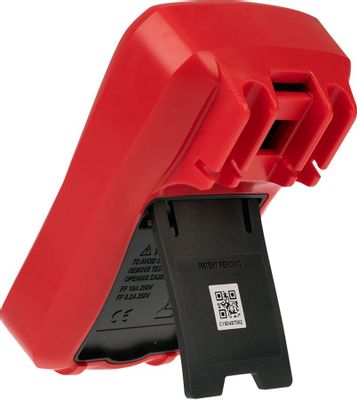
39, 2. Turn the Meter to OFF position. 3. Remove the screw from case bottom, and separate the case bottom from the case top. 4. Remove the battery from the battery compartment. 5. Replace the battery with a new 9V battery (NEDA 1604 or 6F22 or 006P). 6. Rejoin the case bottom and case top, and reinstall the screw. C. Replacing the Fuses (See figure
 Maintenance(3) To avoid electrical shock or arc blas…
 -
27, Measurement Operation (15) G. The Model UT33B: Battery Test (see figure 7) To avoid harms to you or damages to the Meter, please do not attempt to input voltages higher than 60V in DC or 30V in AC. Warning ( figure 7) To test the battery, proceed as follows: 1. Insert the red test into the VΩmA terminal and the black test leads into the COM terminal. 2. Set the rotary switch to an appropriate measurement position …
-
15, Measurement Operation (3) B. AC Voltage Measurement (see figure 2) Warning To avoid harms to you or damages to the Meter from electric shock, please do not attempt to measure voltages higher than 500Vrms although readings may be obtained. The AC voltage measurement positions are: 200V and 500V. To measure AC Voltage, connect the Meter as follows: 1. Insert the red test lead into the VΩmA terminal and the black test lead into the COM terminal. 2. Set the r…
-
6, Safety Information(2) In this manual, a Warning identifies conditions and actions that pose hazards to the user, or may damage the Meter or the equipment under test.A Note identifies the information that user should pay attention on. International electrical symbols used on the Meter and in this Operating Manual are explained on page 10. 6 Model UT33B/C/D: OPERATING MANUAL
… -
18, The Model UT33B: the current measurement has 3 measurement positions on the rotary switch: 200µA, 200mA and 10A. The Model UT33C/UT33D: the current measurement has 4 measurement positions on the rotary switch: 2000µA, 20mA, 200mA and 10A To measure current, do the following: 1. Turn off power to the circuit. Discharge all high-voltage capacitors. 2. Insert the red test lead into the VΩmA or 10A terminal and the black test lead into the COM terminal. 3. Set the rotary switch t…
-
28, UNI-T UT33B Note l When battery testing has been completed, disconnect the connection between the testing leads and the circuit under test. Measurement Operation (16) H. The Model UT33D: Square Wave Output To avoid damages to the Meter, do not allow output terminals (red test lead) to reach higher than 10V. Warning To measure square wave output proceed as follows: 1. Set the rotary switch to OUT. 2. The square wave signal outputs between VΩmA and COM Terminals. Note l The fr…
-
19, Note l If the value of current to be measured is unknown, use the maximum measurement position (10A) l and reduce the range step by step until a satisfactory reading is obtained. l When current measurement has been completed, disconnect the connection between the testing leads l and the circuit under test. Measurement Operation (7) 19 Model UT33B/C/D: OPERATING MANUAL
… -
20, Measurement Operation (8) D. Measuring Resistance (see figure 4) ( figure 4) Warning To avoid damages to the Meter or to the devices under test, disconnect circuit power and discharge all the high-voltage capacitors before measuring resistance. The Model UT33B/UT33C: The resistance measurement positions are: 200Ω, 2000Ω¸, 20kΩ, 200kΩ and 20MΩ The Model UT33D: The resistance measurement positions are: …
-
17, UNI-T UT33B Measurement Operation (5) C. DC Current Measurement (see figure 3) Never attempt an in-circuit current measurement where the voltage between terminals and ground is greater than 60V. If the fuse burns out during measurement, the Meter may be damaged or the operator himself may be hurt. Use proper terminals, function, and range for the measurement. When the testing leads are connected to the current terminals, do not parallel them across any circuit. Warning ( figure …
-
9, l Remove test leads and temperature probe from the Meter and turn the Meter power off before opening the Meter case. l When servicing the Meter, use only the same model number or identical electrical specifications replacement parts. l The internal circuit of the Meter shall not be altered at will to avoid damage of the Meter and any accident. l Soft cloth and mild detergent should be used to clean the surface of the Meter when …
-
26, UNI-T UT33B 2. Set the rotary switch to o C or o F . 3. Place the temperature probe to the object being measured. The measured value shows on the display. Note l The Meter automatically displays the temperature value inside the Meter when there is no temperature probe connection. l The included point contact temperature probe can only be used up to 250 o C(482 o F). For any measurement higher than that, th…
-
7, l Before using the Meter inspect the case. Do not use the Meter if it is damaged or the case (or part of the case) is removed. Look for cracks or missing plastic. Pay attention to the insulation around the connectors. l Inspect the test leads for damaged insulation or exposed metal. Check the test leads for continuity. Replace damaged test leads with identical model number or electrical specifications before using the …
-
40, 3. Remove the screw from case bottom, and separate the case bottom from the case top. 4. Remove the fuse by gently prying one end loose, and then take out the fuse from its bracket. 5. Install ONLY replacement fuses with the identical type and specification as follows and make sure the fuse is fixed firmly in the bracket. 315mA, 250V, fast type, φ 5x20mm. 6. Rejoin the case bottom and case top, and reinstall the screw. Replacement …
 Maintenance(3) To avoid electrical shock or arc blas…
Изображения служат только для ознакомления,
см. техническую документацию
Добавить в корзину 1 шт.
на сумму 2 000 руб.
Номенклатурный номер: 9000567389
Артикул: UT33B+
Бренд / Производитель: Uni Trend Group (UNI-T)

Описание
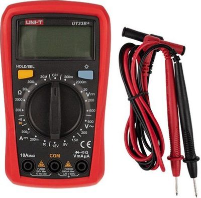
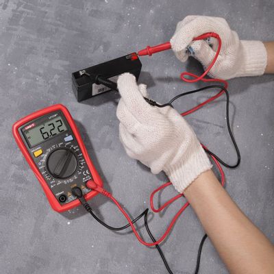
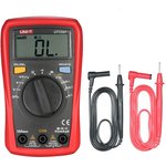
Портативный мультиметр UNI-T UT33B+ 13-0056 позволяет измерить постоянное и переменное напряжение, постоянный ток и сопротивление.
ЖК-дисплей имеет подсветку, благодаря которой облегчается работа в слабоосвещенных местах.
Прибор защищен от перегрузок, что обеспечивает безопасность в эксплуатации.
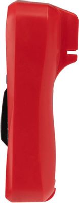
Холстер защищает устройство от механических повреждений в случае падения.
Технические параметры
| Диапазоны измерения постоянного напряжения | 600 | |
| Диапазоны измерения переменного напряжения | 600 | |
| Диапазоны измерения постоянного тока | 10 | |
| Диапазоны измерения переменного тока | 10 | |
| Измерение сопротивления | Да | |
| Измерение емкости | нет | |
| Измерение частоты | нет | |
| Измерение температуры | Да | |
| Функция True RMS | нет | |
| Размеры,мм | 134x77x77 | |
| Госреестр РФ | нет | |
| Выбор пределов измерений | ручной | |
| Вес, г | 336.7 | |
Техническая документация
Сроки доставки
Доставка в регион Курск
| Магазин «ЧИП и ДИП» | 28 сентября1 | бесплатно |
| Курьер | 29 сентября1 | 496 руб.2 |
| ПВЗ 5Post | 28 сентября1 | 99 руб.2 |
| ПВЗ Яндекс Доставка | 28 сентября1 | 99 руб.2 |
| ПВЗ Boxberry | 28 сентября1 | 283 руб.3 |
| ПВЗ Л-Пост | 28 сентября1 | 484 руб.3 |
| ПВЗ СДЭК | 29 сентября1 | 351 руб.3 |
| ТК DPD | 26 сентября1 | 674 руб.2 |
| ТК «Деловые линии» | 27 сентября1 | 843 руб.2 |
| Почта России | 5 октября1 | 286 руб.2 |
Цена и наличие в магазинах
| Курск, ул. Карла Маркса, 68, ТЦ «Мега Гринн», 1 этаж |
нет в наличии |
Розничная цена: 2 000 руб.
2 270 руб.
2 350 руб.
4 710 руб.
230 руб.
2 730 руб.