Перейти к контенту

Сборник руководств на английском языке по эксплуатации и техническому обслуживанию квадроциклов CFMoto моделей CF500/CF500-A/CF500-5B/CF500-5C/CF625-B/CF625-C.
- Издательство: —
- Год издания: —
- Страниц: —
- Формат: PDF
- Размер: 74,3 Mb
Руководство на английском языке по техническому обслуживанию и ремонту квадроциклов CFMoto моделей CF500 и CF500-A.
- Издательство: Chunfeng Holding Group
- Год издания: 2006
- Страниц: 254
- Формат: PDF
- Размер: 12,8 Mb

Руководство на русском языке по эксплуатации и техническому обслуживанию квадроциклов CFMoto модели CF500-A.
- Издательство: —
- Год издания: —
- Страниц: 206
- Формат: PDF
- Размер: 2,8 Mb
Руководство на русском языке по ремонту квадроциклов CFMoto модели CF500-A.
- Издательство: —
- Год издания: —
- Страниц: 266
- Формат: PDF
- Размер: 15,8 Mb

Руководство на русском языке по эксплуатации и техническому обслуживанию квадроциклов CFMoto моделей CF500-2 и CF500-2A 2008 года выпуска.
- Издательство: —
- Год издания: —
- Страниц: 144
- Формат: PDF
- Размер: 6,9 Mb

Руководство на русском языке по эксплуатации и техническому обслуживанию мотовездехода CFMoto модели CF500-3 с полным приводом.
- Издательство: —
- Год издания: —
- Страниц: 163
- Формат: PDF
- Размер: 2,1 Mb
Руководство на английском языке по техническому обслуживанию и ремонту квадроциклов CFMoto моделей CF500-5B и CF500-5C.
- Издательство: Zhejiang CFMOTO Power Co., Ltd.
- Год издания: 2009
- Страниц: 272
- Формат: PDF
- Размер: 23,2 Mb

Руководство на английском языке по эксплуатации и техническому обслуживанию мотовездеходов CFMoto Terracross моделей CF500-6/CF625-3/CF625-6 с полным приводом.
- Издательство: —
- Год издания: —
- Страниц: 135
- Формат: PDF
- Размер: 16,9 Mb

Руководство на русском языке по эксплуатации и техническому обслуживанию квадроциклов CFMoto модели CF625-X6 EFI.
- Издательство: —
- Год издания: —
- Страниц: 157
- Формат: PDF
- Размер: 43,8 Mb
Руководство на русском языке по эксплуатации и техническому обслуживанию квадроциклов CFMoto модели CF800-2X8 EFI.
- Издательство: —
- Год издания: —
- Страниц: 162
- Формат: PDF
- Размер: 3,4 Mb

Руководство на английском языке по техническому обслуживанию и ремонту квадроциклов CFMoto модели CF800-2 Terralander 800 с полным приводом.
- Издательство: Zhejiang CFMOTO Power Co., Ltd.
- Год издания: 2011
- Страниц: 316
- Формат: PDF
- Размер: 16,5 Mb

Руководство на французском языке по эксплуатации и техническому обслуживанию квадроциклов CFMoto моделей Goes 520 и Goes 520 Max с полным приводом.
- Издательство: —
- Год издания: —
- Страниц: 30
- Формат: PDF
- Размер: 2,7 Mb

Руководство на русском языке по эксплуатации и техническому обслуживанию квадроциклов CFMoto моделей HX500-S и HX500-L 2009 года выпуска.
- Издательство: —
- Год издания: —
- Страниц: 146
- Формат: PDF
- Размер: 3,8 Mb
Руководство на чешском языке по эксплуатации и техническому обслуживанию квадроциклов CFMoto модели JourneyMan Gladiator RX.
- Издательство: —
- Год издания: —
- Страниц: 31
- Формат: PDF
- Размер: 1,1 Mb

Руководство на чешском языке по эксплуатации и техническому обслуживанию квадроциклов CFMoto модели JourneyMan Gladiator X-8.
- Издательство: —
- Год издания: —
- Страниц: 24
- Формат: PDF
- Размер: 802 Kb

Руководство на чешском языке по эксплуатации и техническому обслуживанию мотовездеходов CFMoto модели JourneyMan Gladiator Z6.
- Издательство: —
- Год издания: —
- Страниц: 24
- Формат: PDF
- Размер: 823 Kb

Руководство на русском языке по эксплуатации и техническому обслуживанию мотовездеходов CFMoto модели SSV 625-Z6 EFI с полным приводом.
- Издательство: —
- Год издания: —
- Страниц: 131
- Формат: PDF
- Размер: 5,7 Mb
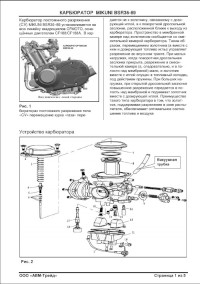
Руководство на русском языке по ремонту карбюратора Mikuni модели BSR36-89.
- Издательство: —
- Год издания: —
- Страниц: 5
- Формат: PDF
- Размер: 393 Kb
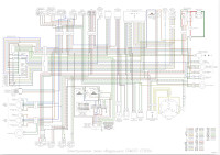
Электросхемы на русском и английсом языках квадроциклов CFMoto моделей CF500/CF500-A/CF500-X5/CF625-X6/CF800-2-X8.
- Издательство: —
- Год издания: —
- Страниц: —
- Формат: PDF
- Размер: 5,1 Mb

- Manuals
- Brands
- CF MOTO Manuals
- Offroad Vehicle
- X5 EFI 2009
- Service manual
-
Contents
-
Table of Contents
-
Troubleshooting
-
Bookmarks
Quick Links
CFMOTO
Service
CF500-5B
CF500-5C
Manual
WWW.CFMOTO.COM
Related Manuals for CF MOTO X5 EFI 2009
Summary of Contents for CF MOTO X5 EFI 2009
-
Page 1
CFMOTO Service CF500-5B CF500-5C Manual WWW.CFMOTO.COM… -
Page 2
WWW.CFMOTO.COM All rights reserved Zhejiang CFMOTO Power Co., Ltd. Aug. 2009… -
Page 3: Table Of Contents
FORWARD CONTENTS Maintenance information This manual introduces X5 EFI version (CF500- 5B/5C) maintenance information, disassembly V ehicle body! Muffler procedure, check & adjustment methods, trouble- Checking& Adjustment shooting and technical specifications. There are illustrations, drawing to guide your operations. Cooling&Lubricating system Engine disassembly&assembly Chapter 1 mainly introduces general operation information, tools, vehicle structure and basic…
-
Page 4
Conversion table Item Example Conversion Pressure 200 kPa»2.00kgf / cm 1kgf / cm =98.0665kPa 1kpa=1000Pa 33kPa (250mmHg) 1mmHg=133.322Pa=0.133322kPs Torque 18N#m»1.8kgf -m) 1kgf#m=9.80665N#m Volume 419ml 1ml=1cm =1cc 1l=1000cm Force 12N»1.2kgf$ 1kgf=9.80665N… -
Page 5: Maintenance Information
1. Maintenance Informat ion C a u t i o n ! ! ! ! ! ! ! ! ! ! 1 — 1 Tightening Torque!!!!!!!!1-13 Numbers Marking Locations!!!!!1-3 Grease & Seasant!!!!!!!!1-18 Main Parameters Table Wiring, Pipe & Cables Layout!!!1-19 !!!!!1-4 Maintenance Parameters Table!!!1-6 Failure Indicator!!!!!!!!1-23…
-
Page 6
CFMOTO 14 . Turn the i nner and outer r i ngs of ba l l bear i ng to make sure the bear i ng w i l l turn smooth l y . «Rep l ace i f the ax i a l or rad i a l p l ay i s too b i g . «I f the surface is uneven, clean wi th oi l and replace i f the clean ing does not help.When press i ng the bear i ng i nto the mach i ne or to the shaf t . -
Page 7
1. Maintenance Informat ion Numbe r s Ma r k i ng L ocat i on CF500 — 5B / CF500 — 5C V I N Number! ! LCELDTS5″ » / LCELDTS6 Eng i ne Numbe r ! ! CF188 — B» «… -
Page 8
CFMOTO Ma i n Dat a Tab l e Item Parameter Model CF500-5B/CF500-5C Length CF500-5B: 2100mm CF500-5C: 2300mm Width 1180mm Height 1230mm Wheel base CF500-5B: 1290mm CF500-5C: 1490mm Engine type CF188 Displacement 493C m Fuel type Unleaded gasoline RQ-90or above Dry weight CF500-5B: 344 kg CF500-5C: 358 kg… -
Page 9
1. Maintenance Informat ion Item Parameter Air Filter type Sponge element filter Fuel Type Type: CF188-B-173000 Devic e Valve Diameter mixing 36mm valve Clutch W et, A uto-Centrifugal Operation Automatic$ CVT% +P arking & Gear S hi fting Mode Gears Shift Low Gear, High Gear &… -
Page 10
CFMOTO Maintenance Parameters Table L ub r i ca t i on Sys t em Item Standard Service Limit Engine Oil Volume when 1900mL Capacity replacing Volume when 2200mL replacing filter ·Specially for 4-stroke motorcycle Recommended Oil$See Original% SAE-15W-40 Substitutes must be used in the following range. -
Page 11
1. Maintenance Informat ion Coo l i ng Sys t em Ser vice It em Standard/ Par amet er Remar k Li mit Ful l Capacit y 2000ml Reservoir t ank capacit y 300ml Standard Densi ty Opening pr essur e of radiator 108kpa(1.1kgf/ cm Init ial 71±3&… -
Page 12
CFMOTO F r on t Whee l Opera tio n Ite m Stand ar d L im it 1. 0mm 2.0mm Pl ay o f whe e l Ve rtica l 1. 0mm 2.0mm H orizo nta l F ront W he e l 3.0mm Groove Tire… -
Page 13
1. Maintenance Informat ion Bat te ry , Cha rg i ng Dev i ce , P i ckup Co i l Item Standard Model Permanentmagnet AC Type Output 3-phas e AC Chargi ng Coil Resistance$ 20? % 0.2″-0.3″ Pickup Coil Resis tance 110″-140″… -
Page 14
CFMOTO (mm) Air Inl et Device+ Cyl i nder Head Item Standard Operation Limit Intake 30.6 Valve Diameter Exhaust 27.0 Intake 0.05-0.10 Valve Clearance( Idle Speed) Exhaust 0.17-0.22 Fit Clearance between Valve Intake 0.010-0.037 Guide and Valve Stem Exhaust 0.030-0.057 Internal dia. -
Page 15
1. Maintenance Informat ion (m m ) Cy l i n der + P i sto n + P ist on R ing + Cran ksh af t Operation Item Standard R emark Limi t C ylinder Pressure 1000kPa F it C learance betw een 0.030-0.051 0.15 P iston and C ylinder… -
Page 16
CFMOTO Clutch + Transmission (mm) Item Standard Limit Remark Clutch Friction plate inner dia. 140.00-140.15 140.50 Clutch Joint Rotation 1800-2400r/min Clutch lock-up Rotation 3300-3900r/min Drive Belt Width 35.2 33.5 Driven Disc Spring Free Length Shifter and fit flute gap 0.10-0.40 0.50 Left Shifter Sliding Thickness 5.8-5.9… -
Page 17
1. Maintenance Informat ion Tightening Torque Item Torque N·m(kgf·m) Item Torque N·m(kgf·m) 5mm Bolt, nut 5(0.5) 5mm Screw 4(0.4) 6mm Bolt, nut 10(1.0) 6mm Screw 9(0.9) 8mm Bolt, nut 22(2.2) 6mmSH Bolt with flange, 10(1.0) 10mm Bolt, nut 34(3.5) 6mm Bolt with flange, nut 12(1.2) 12mm Bolt, nut 54(5.5) -
Page 18
CFMOTO Engine Tightening Torque Table Torque Item Q’ty Screw dia.$mm% Remark $N.m% Sensor, Reverse Gear M10!1.25 Spark Plug M12!1.25 Water Temperature Sensor Rc1/8 Apply screw thread sealant Valve Clearance Adjusting Nut Drive Disc Nut M20!1.5 Driven Disc Nut M20!1.5 Circle Nut, Driving Disc M30!1 Nut, Front Output Shaft M14!1.5… -
Page 19
1. Maintenance Informat ion To be continued Torque Item Quantity Diameter$mm% Remark $N.m% Bolt, Crankcase Bolt, Driven Sector Gear Mounting Bolt, Oil Filter M20!1.5 Oil Filter 3 / 4 ? $ 1 6 / i n 18’20 Bolt, Starting Motor Bolt, Cylinder Head Bolt, Cylinder Head(2 sides) Upper and Lower Bolt, Cylinder… -
Page 20
CFMOTO Engine Tools Measuring Tools Name Type Function Remark Vernier Calipers 0-150mm Measure length and thickness Measure the outer diameters of swing Micrometers 0-25mm arm, valve rod and camshaft Dial gauge 25-50mm Measure max. lift range of camshaft Dial gauge 75-100mm Measure piston skirt Inner dia. -
Page 21
1. Maintenance Informat ion Special Purpose Tools Name Type Function Remark Spark Plug Wrench 172MM-022400-922-004 Disassemble/ install spark plug CF188-051000-922-001 Disassemble/install CVT CVT Wrench CF188-052000-922-001 drive/driven disc nut Oil Filter Wrench CF188-011300-922-001 Disassemble/ install oil filter Piston Pin Remover CF188-040004-922-002 Disassemble piston pin Magneto stator CF188-031000-922-001… -
Page 22
CFMOTO Lubr icant Grease, Sealant Coated Section Attention Grease Turning Bearings Throttle Cable Connecting Portion Throttle Pedal Movable Parts Brak e Pedal Movable Parts Multi-purpos e Swing Arm Movable Parts grease Steering Inner Circle Surfac e Seat Lock Movable Parts Transmission Movabl e Parts Opera tion Material and Installment Supplementary of Engine Engine operation materials include lubricant (oil), grease (lubricant grease) and coolant, installment… -
Page 23
1. Maintenance Informat ion W i r i ng , P i pes , Cab l e Layout Picture 2 Picture 1 Picture 3 1-19… -
Page 24
CFMOTO 1-20… -
Page 25
1. Maintenance Informat ion 1-21… -
Page 26
CFMOTO 1-22… -
Page 27
1. Maintenance Informat ion Fa i l u r e I nd i ca t o r Fa i l ure Ind i actor i s l ocated on the left top !»#of instrument . Whi le the indicator f lashing is faulty, fai lure uses 4-digi t f lashing. -
Page 28
2 Vehicle Body and Muf f ler Overhaul Info !!!!!!!!!!!!!!2 — 1 Footrest Board (LH, RH) !!!!!!!!!!2-10 Troubleshooting !!!!!!!!!!!!!!2 — 1 Rear Fender, Engine Skid Plate (Front, Center, Rear), Front Rack, Bolt Cap Double Seat, Protection Plate !!!!!!!!!!!!2-2 !!!!!!!!2-11 Seat, Seat Support & Rear Rack !2 -13 !!!!!!!!2-3 Front Inner Fender (R&H), Front Protector (RH, LH) -
Page 29
CFMOTO Front Rack, Bolt Cap Remove: Upward l y remove Bo l t cap hard ; two assemb l y bo l ts of f ront rack shal l be seen . Remove fixing Bolt 1 (one for each on theleft and right) Romove f i x i ng Bo l t 2 Remove f ront rack Installation:… -
Page 30
2 Vehicle Body and Muf f ler Seat Remove: Pull upward seat buckle Lift and push seat backward Installation: Press upward seat buckle Press seat forward and down Note: Shake seat left,right, front and back to make sure that the seat is firmly installed. Remove: «… -
Page 31
CFMOTO Fr on t Top Cove r Remove F r on t Rack %» 2 — 2& 6 nu t s’ Front Top Cover Assemb l e Reverse the remova l process and d i rect i on . Dashboa r d Cove r Remove — -2 pieces Bol t 1 — -2 pieces bol t 2… -
Page 32
2 Vehicle Body and Muf f ler F r on t S i de Suppo r t ( L e f t ) Remove Bol t 1 Front Side Support Assemb l e Reverse the remova l process and d i rect i on . F r on t S i de Suppo r t ( R i gh t ) Same as Left Side Support… -
Page 33
CFMOTO Rear Top Cover Remove Rea r Rack %» 2 — 3& Seperate c l asps of rear top cover f rom rear fender ; Remove Rear Top Cover I nsta l l at i on Reverse the remove procedure and d i rect i on for i nsta l l at i on . -
Page 34
2 Vehicle Body and Muf f ler L e f t S i de Cove r Remove — — S e a t %» 2 — 3 & — — Lef t S i de Cover f i x i ng bo l t — — Lef t S i de Cover I nsta l l at i on Reverse the remove procedure and… -
Page 35
CFMOTO Rear S i de Pane l Remove — — S e a t %» 2 — 3 & — — R i ght S i de Cover F i x i ng Bo l t Remove connect ing Bol t 1 between Right Side Panel and Front Fender at bottom of Front Fender Remove R i ght S i de Panel… -
Page 36
2 Vehicle Body and Muf f ler Top Cover , Fue l Tank Remove — — S e a t %» 2 — 3 & — — F r on t Rack%» 2 — 2& — — Front Top Cover%» 2 — 4& — — Le f t S i de Pane l %»… -
Page 37
CFMOTO Foo t r es t , L e f t S i de Remove Le f t S i de Pane l %» 2 — 7& Remove three Bo l t 1 and 3 nuts connect i ng w i th Front Fender Remove three Bo l t 2 and 3 nuts connect i ng w i th Rear Fender Remove Bo l t 1… -
Page 38
2 Vehicle Body and Muf f ler Rear Fender Remove — — S e a t %» 2 — 3 & — — Rea r Rack%» 2 — 3& — — Rear Top Cover%» 2 — 6& — — L e f t , R i gh t S i de Pane l %» 2 — 7& %» 2 — 8& — — Le f , R i ghtS i de Suppor t%»… -
Page 39
CFMOTO D i sasemb l y NOTE : S i de sk i d P l ate ( Front , M i dd l e , Rear ) and Doub l e Sea t P r o t ec t i on a r e l oca t ed a t bo t t om o f veh i c l e . -
Page 40
2 Vehicle Body and Muf f ler R i ght Front I nner Fender Remova l Remove Bo l t 1 , and remove R i ght Front Inner Fender Insta l l at i on Reverse the remove procedure for Insta l l a — t i on NOTE : Hook Water Pump w i th C l i p o f R i ght I nne r S i de Fende r du r i ng I ns t a l l a t i on . -
Page 41
CFMOTO Fr on t L e f t I nner Fender Remova l Remove Bo l t 1 and 2 ; Remove Front Lef t Inner Fender I n s t a l l a t i o n Reverse the remove procedure for Insta l l a — t i on Fr on t R i gh t I nner Fender Remova l and Instal l at i on same as Lef t S i de. -
Page 42
2 Vehicle Body and Muf f ler Bumper Protector Remove — — Loosen Front Turn i ng L i ght Connector . — — Remove Bumper and Bumper Protector . Remove tapp i ng screw 1 f rom Bumper ; Remove Bumper Protector . -
Page 43
CFMOTO F r on t Ven t Gr i l l Remove — — Loosen Connector of Front Head L i ght — — Remove Front Fender%» 2 — 9& — — Remove Bumpe r%» 2 — 14& — — Remove Bo l t 1 , 2 and 3 ; — — Remove Vent Gr i l l No t e : Fo r r emova l o f f r on t ven t g r i l l e o n l y ,… -
Page 44
2 Vehicle Body and Muf f ler Remove Fuel P i pe 1 and C i rcl i p Remove Fuel Tank I nsta l l at i on : Reverse the remova l procedure f or i nsta l l at i on Note: Be careful not to damage main cable, pipes and hoses. -
Page 45
CFMOTO Mu f f l e r Caut i on : Per form d i sassemb l y on l y af ter the muf f l er i s coo l ed down . Remo ve : — — Seat (2 — 3) — — R i ght s i de pane l (2 —— — Nut1 , Nut 2 for exhaust p i pe e l bow…
-
Page 46
2 Vehicle Body and Muf f ler V i s i b l e Pa r t s 2-19… -
Page 47
3 . Checks & Ad j ustment Overhaul Info……………………… 3-1 Cooling System..…………………………3-13 Maintenance Interval………………..3-2 Lighting System……………………… ……3-16 Inspection & Maintenance………… ………3-3 Valve Clearance……………… …………..3-17 Steering S tem, Brake System………………3-6 Engine Idle S peed & Spark plug………… 3-18 Wheel s ……………………………… ……….3-8 Air Filter……………………………….3-19 Suspension System………………. -
Page 48: Maintenance Interval
CFMOTO Maintenance Interval T he table below lists the recommended interv als for all the required periodic maintenance work nec es sary to k eep the engine at its best performanc e and economy. Maintenanc e intervals are ex pressed in terms of k ilometer, miles and hours, whichever occurs firs t. Note: Maintenance interval sh ould be sh ortened on eng ines that are used in severe conditions.
-
Page 49: Inspection & Maintenance
3 . Checks & Ad j ustment Inspection & Maintenance ! ! : Interval Item Intervals Standard Daily Part Item Annual Year Operation agility Handlebar » Damage » Steering Steering System Installation condition of steering system » system Sway of ball stud «…
-
Page 50
CFMOTO Item Intervals Daily Standard Part Item Annual Year Final Looseness of joint parts shaft Drive train Sway of Spline (Drive shaft) Spark plug gap: Ignition Spark plug 0.8-0.9mm Device Electrical Ignition timing System Battery Terminal Joint Looseness and damage of Wiring joints Fuel leakage… -
Page 51
3 . Checks & Ad j ustment It e m I n terv als Daily Standard Pa rt I tem A n n u a l Year Lighting devi ce and Function » » turning indic tors Alarm and lock devic e Function «… -
Page 52
CFMOTO Steer i ng Stem Park the veh i cl e on l evel p lace, ho l d steer — i ng hand l ebar , and shake i n the di rect i on as i l l ustrated on the r i ght and see i f there i s any sway . -
Page 53
3 . Checks & Ad j ustment Master Cy l i nder <Fluid level> Check the brake f luid level When the brake f l u i d l eve l i s near to the lower l imi t l ine, check master cyl inder , brake hoses and jo i nts for l eakage. -
Page 54: Wheel S
CFMOTO W he e l s L i f t f ront whee l on l eve l p l ace , and make sure there i s no l oad i ng on the wheel s . Shake the front wheel left and r ight to check whether the joint of front wheel is t ightened and check whether i t sways .
-
Page 55
3 . Checks & Ad j ustment T i r e P r essu r e Check the pressure of the t i res w i th a pressure gauge. No t e Check the t i re pressure af ter t i res are coo l ed . -
Page 56: Suspension System
CFMOTO Whee l Nu t and Whee l Ax l e Check front and rear wheel axle nuts for loose- ness Loosened ax l e nuts : # T i ghten T i ghten i ng Torque : Front wheel axl e nut : 110 — 130N .
-
Page 57
3 . Checks & Ad j ustment Ad j us t i ng t he Abso rbe r Use speci a l too l s to ad j ust the l ength of absorber accord i ng to l oad i ng requ i rement Turn cl ockw i se to ad j ust f rom h i gh to l ow Gea r Sh i f t i ng Sh i f t the gear to check for f l exi b i l i ty and… -
Page 58
CFMOTO Check i ng t he Th r o t t l e L eve r Check t he f r ee p l ay o f t h r o t t l e l eve r Free p l ay : 3 — 5mm Out of range : # Ad j ust Loosen l ocknut of thrott le cab l e turn the regu l ator and ad j ust f ree p l ay of… -
Page 59: Cooling System
3 . Checks & Ad j ustment Coo l i ng Sys t em No t e Check coo l ant l evel f rom reservo i r tank. Do not check f rom rad i ator . I f the rad i ator cap i s opened wh i l e the eng i ne i s hot (over 100$) , the pressure of the coo l i ng system w i l l drop down and the coo l ant w i l l get bo i l ed rap i d l y .
-
Page 60
CFMOTO When the coo l ant l eve l i s be l ow the LOWER l i m i t , remove reservo i r tank cap and add coo l ant t i l l upper l i m i t . (Add coo l ant or d i l uted or i g i na l l i qu i d) . -
Page 61
3 . Checks & Ad j ustment I nspect i on o f Coo l i ng System Check ini t ial ly at 50 hours or 500km, replace coo l ant every 2 years . Check radiator, reservoi r tank and water hoses. Leakage or Damage : # Rep l ace Check coo l ant l eve l by observ i ng the upper and the l ower l i m i t on the reservo i r tank. -
Page 62: Lighting System
CFMOTO Check Water Temperature Gauge When eng i ne i s not work i ng , the water tem — perature shou l d be i n the *0+ pos i t i on . Start the eng i ne to check i f the i nd i cator works .
-
Page 63: Valve Clearance
3 . Checks & Ad j ustment VA L VE C L EARANCE Inspect i n i t i a l l y at 20 — hour break — i n and every 100 hours or every 1000km thereaf ter . Inspect the cl earance af ter remov i ng cy l i n — der head .
-
Page 64
CFMOTO Take ou t t he f ee l e r gauge , measu r e t he c l earance . I f the c l earance i s i ncorrect , repeat the above steps unt i l the proper c l earance i s obta i ned . -
Page 65: Air Filter
3 . Checks & Ad j ustment I n case o f carbon depos i t , c l ean w i th a proper too l . SPARK PLUG GAP Measure the spark p l ug gap w i th a fee l er gauge .
-
Page 66
CFMOTO A — — Non — f l ammab l e cl ean i ng so l vent B 1 Eng i ne o i l SAE#30 or SAE15W / 40 . Never use w i th gaso l i ne or l ow f l ash po i nt so l vents to c l ean the f i l ter e l ement Inspect the f i l ter e l ement for tears . -
Page 67
3 . Checks & Ad j ustment I nspect i on : Inspect dr i ve bel t for wear and damage. I f any cracks or damages are found , rep l ace dr i ve bel t w i th a new one. Inspect dr i ve bel t for w i dth , i f w i dth i s out of serv i ce l i m i t , rep l ace dr i ve be l t w i th a new one. -
Page 68: Inspection Of Lubrication System
CFMOTO I nspect i on o f Lubr i cat i on System Rep l ace eng i ne o i l and o i l f i l ter i n i t i a l l y at 20 hours or 250km and every 100 hours or 1000km thereaf ter .
-
Page 69
3 . Checks & Ad j ustment — Insta l l o i l d i p rod , start the eng i ne and al low i t to run for several minutes at idl ing speed . — Turn of f the eng i ne and wa i t f or about 3 m inutes , and then check the o i l l evel on the d i pst i ck . -
Page 70: Inspection Of Cylinder Pressure
CFMOTO I nspect i on o f cy l i nder pressure Check cy l i nder pressure i s necessary . Cy l i nder Pressure: 1000kpa A l ower cy l i nder pressure may be caused by : — Excess i ve wear of cy l i nder ;…
-
Page 71
3 . Checks & Ad j ustment I nspect i on o f O i l P ressu r e O i l Pressure : 1303170kpa at 3000r / m i n Lower or h i gher o i l pressure may be caused by : ! ! O i l p r essu r e i s t oo l ow — C l ogged o i l f i l ter ;… -
Page 72: Inspection Of Clutch Engagement And Lock-Up
CFMOTO I nspect i on of C l utch Engagement and Lock — up CF188 — B eng i ne i s equ i pped w i th a centr i fu — gal type automat i c cl utch . Before check i ng the i n i t i a l engagement and cl utch lock-up two i nspect ion checks must be per formed to thorough l y check the operat i on…
-
Page 73
4 Coo l i ng and L i br i cat i on System Overhaul Info !!!!!!!!!!4 — 1 Rad i ator and water hose check and c l ean!!4 — 9 Troub l e Shoot ing !!!!!!!!4 — 2 Coo l i ng fan check!!!!!!!!!!!!!4 -10 Per formance Overhau l !!!!!!4 — 3 Water temperature transducer check!!!!4 — 11… -
Page 74
T r o ub l e sh o o t i n g Wa t e r t empe r a t u r e r i ses t oo f as t «Improper rad i ator cap «A i r i n the coo l i ng system p i pe «Mal funct i on of water pump «Ma l funct i on of thermostat%thermostat i s not open&… -
Page 75
4 Coo l i ng and L i br i cat i on System P e r f o r m an ce O v e r h au l I nspec t i on o f coo l an t dens i t y C a u t i o n : Be sure to open the radiator cap after coolant i s coo l ed . -
Page 76
P r essu r e t es t i ng o f coo l i ng sys t em App l y the spec i f i ed pressure( rad i ator cap opening pressure) for 6 seconds and make sure that there i s drop i n pressure C a u t i o n Do not app l y pressure over the spec i f i ed… -
Page 77
4 Coo l i ng and L i br i cat i on System Remove d r a i n bo l t Remove drai n bo l t , seal gasket f rom water pump , dra i n coo l ant . Af ter drai nage, assemb l e new sea l gasket and drai n bo l t and t i ghten . -
Page 78
A dd i n g C o o l an t Add coo l ant through f i l l i ng port Start the engine and discharge ai r from cool — i ng system . Check f rom f i l l ing port that ai r i s fu l l y d i scharge f rom coo l i ng system and i nstal l the rad i ator cap Remove reservo i r tank cap and add coo l ant… -
Page 79
4 Coo l i ng and L i br i cat i on System Coo l i ng Sys t em… -
Page 80
— E ng i n e Co o l an t The cool ing used in cool ing system is mixture of 50% d i st i l l ed water and 50% ethy l ene gl y — co l ant i f reeze . Th i s 50 : 50 m i xture prov i des the opt i m i zed corros i on res i stance and f i ne heat protect i on . -
Page 81
4 Coo l i ng and L i br i cat i on System — I n s p ec t i o n an d C l ean i n g o f R ad i a t o r and Wa t e r Hoses R ad i a t o r Cap . -
Page 82
I nspec t i on o f Fan Mo t o r . Remove fan motor f rom rad i ator . Turn the vanes and check i f they can turn smooth l y . Check fan motor .Make sure that the battery app l i es 12 vo l ts to the motor and the motor wi l l run at ful l speed whi le the ammeter wi l l i nd i cate the ampere not more than 5A . -
Page 83
4 Coo l i ng and L i br i cat i on System — Inspect i on of Water Temperature Sensor . P lcae a rag under water temperature sensor / and remove i t f rom cyc l i nder head . -
Page 84
. Check ther mos tat pe l l et f or cracks . I f necessary , rep l ace i t . . Test the thermostat accord i ng to the fo l — l ow i ng steps : 3 Pass a str ing between thermostat f l ange as i l l ustrated on the r i ght 3 Immerse the thermostat i n a beaker w i th… -
Page 85
4 Coo l i ng and L i br i cat i on System . Remove c l amps and water hoses . Re l ease bo l ts and remove water pump . Remove O — r i ng No t e : Do no t r euse t he O — r i ng . -
Page 86
. Remove mechan i cal sea l w i th spec i a l too l Note# # The mechan i ca l sea l does not need to be moved , i f there i s no abnormal cond i t i on . Note : Do not reuse a removed mechan i ca l sea l . -
Page 87
4 Coo l i ng and L i br i cat i on System ) ) O i l S ea l . Check o i l sea l for damaged . Pay attent i on to the o i l seal l i p . . -
Page 88
. Insta l l mechan i ca l sea l w i th a su i tab l e socket wrench . No t e : App l y sea l an t to s i de 4A5 o f me — chan i ca l sea l . -
Page 89
4 Coo l i ng and L i br i cat i on System . Instal l r i ng to water pump shaf t . Instal l new gasket to water pump body . Insta l l water pump cover and t i ghten the bo l ts and b l eed bo l t W a t e r P u m p… -
Page 90
. Insta l l water pump and t i ghten the bo l ts to the speci f i ed torque Wa t e r pump bo l t s t i gh t en i ng t o r que : 10N( ( m Note : Set the water pump shaf t s l ot end 4B5 to o i l pump sha f t f l at s i de 4A5 . -
Page 91
4 Coo l i ng and L i br i cat i on System 4-19… -
Page 92
Add grease to the eng i ne parts(p i ston , cy l i n — der body , camshaf t and so on) wh i ch run at h i gh speed Eng i ne l ubr i cat i on shou l d be spec i a l o i l . Eng i ne o i l i s not on l y used as l ubr i cat i on , but also used to wash, rustproof ,seal and cool . -
Page 93
Removal and Installation of Engine,Drive Traina and Gearshift Unit Remova l and Insta l l at i on of Front and Rear Overhaul Info###############5-1 Alex ##################5-5 R emo v a l an d I n s t a l l a t i o n o f G ea r s h i f t Engi ne Removal and Instal l at ion##### 5-2 Uni t####################5-7 Overhau l Info… -
Page 94
CFMOTO Engine Removal Remove: —Plastic( —Chapter 2) —Air Filter( -Engine service chapter) —Carburetor (-Engine service chapter) —Clamp —Water Inlet Hose Remove screw Remove gearshift rod Remove clamp Remove water outlet hose Remove Sleeve. Remove connectors of magneto, enriching device lead, pickup, water temperature transducer, gear sensor as illustrated on the right. -
Page 95
Removal and Installation of Engine,Drive Traina and Gearshift Unit Remove spark plug cap from cylinder Remove protection sleeve of starter relay. Remove Nut. Disconnect positive wire of starter relay. Remove nut. Remove negative wire of starter relay. -
Page 96
CFMOTO Remova l Bo l t (4 un i ts) of Eng i ne. -
Page 97
Removal and Installation of Engine,Drive Traina and Gearshift Unit Eng i ne I nsta l l at i on Put eng i ne onto the f rame , i nsta l l the two l ower mount i ng bo l ts and nuts Tightening torque: 50!60N»m Engine lower hanger bolt:… -
Page 98
CFMOTO Remove nut and bolt of front axle from frame. Remove nut and bolt of rear axle from frame. -
Page 99
Removal and Installation of Engine,Drive Traina and Gearshift Unit Remove the 18 bo l ts f or dr i ve sha f ts and f ront and rear ax l es$Refer to 5’bo l t 3) Remove Front and rear axl es , dr i ve shaf ts , rear brake d i sc I nsta l l at i on Reverse the remova l procedure for Insta l l a -… -
Page 100
6 Engine Removal , Inspect ion & Instal lat ion 6 Engine Removal, Inspection and Installation ! ! Engine Removal/Installation Orders and the Relative Page Numbers Disassembly Inspection / Remarks Assembly Maintenance gine 2-11 3-69 Water Hose/Pipe iphery 3-69 Left Side Cover 3-49 3-68 Recoil Starter… -
Page 101
» » Eng i ne Remova l ! Preparat ion before engine removal » Prepare a proper tray used for l oad of components » Prepare necessary remova l and assemb l y too l s » Dra i n up eng i ne o i l $3 — 22& «… -
Page 102
6 Engine Removal , Inspect ion & Instal lat ion Cylinder Head Cover » Remove valve adjusting cover » Remove12 bolts of cylinder head cover » Remove cylinder head cover Timing Chain Tensioner » Remove screw plug , insert a flat screwdriver into slot of timing chain tensioner adjuster , turn it clockwise to lock tensioner spring;… -
Page 103
» Remove C-ring » Remove timing sprocket from camshaft, remove camshaft Note: Take care not to drop spacer, bolt, bolt lock and C-ring into crankcase. » Remove tensioner plate Cylinder Head » Remove cylinder head bolt » Remove cylinder head bolts diagonally; «… -
Page 104
6 Engine Removal , Inspect ion & Instal lat ion » Remove cylinder bolt » Remove cylinder Note Take care not to drop dowel pin into crankcase » Remove dowel pin and cylinder gasket Note When performing above removal process, be sure to hook up timing chain to prevent it from falling into crankcase Piston… -
Page 105
Oil Filter » R emove oil filter with special tools Tool: Oil filter Remover Sector Gear » Remove bolt 1 of gearshift rocker arm » Remove gasket 2 and gearshift rocker arm 3 » Remove bolt of sector gear housin cover «… -
Page 106
6 Engine Removal , Inspect ion & Instal lat ion Water Pump » Screw out bolt of water pump » Remove water pump Sheave Drum » Remove the sheave drum by using a suitable bar; » Remove washer and sheave drum Left Crankcase Cover Remove bolts;… -
Page 107
Starting Motor Gear » Remove driven gear 1 and needle bearing » Remove spacer 2 » Remove dual gear and shaft 3 » Remove idle gear and shaft 4 Oil Pump Sprocket and Chain » Remove drive sprocket nut 5 «… -
Page 108
6 Engine Removal , Inspect ion & Instal lat ion Engine Right Side CVT Cover » Remove bolt of CVT cover » Remove CVT cover » Remove gasket and dowel pin CVT(Continuously Variable Transmission) » Remove primary sheave nut with special tool «… -
Page 109
CVT Case » Remove bolt 1 of CVT case » Remove nut 2 of CVT case » Remove outer clutch face and CVT case » Remove dowel pin, front and rear gasket Clutch » Remove clutch shoe fixing nut with special tool «… -
Page 110
6 Engine Removal , Inspect ion & Instal lat ion Engine Center Gear position bolt » Remove gear position bolt » Remove spring and steel ball Right Crankcase » Remove left crankcase bolts » Remove right crankcase bolts » Separate right crankcase with special tool Caution «… -
Page 111
» Remove Oil seal Bearing limit nut $ l e f t r o l l & » Remove Front Output Shaft Shift Cam, Fork/Shaft » Remove Shift Cam Fork /Shaft Drive Bevel Gear » Remove left crankcase from driven bevel gear Drive Shaft, Drive Shaft «… -
Page 112
6 Engine Removal , Inspect ion & Instal lat ion Crankshaft » Separate crankshaft from left crankcase with spe- cial tool Tool: Crankshaft Separator Oil bump, Relief Valve » Remove oil bump and relief valve 6-13… -
Page 113
Engine Components Inspection Cylinder Head Cover Disassembly Caution Each removed part should be identi- fied to its location, and the pars should be laid out in groups designated as ¡°Exhaust¡±, ¡°Intake¡±, so that each will be restored to the original location during assembly. -
Page 114
6 Engine Removal , Inspect ion & Instal lat ion Rocker Arm » When checking the rocker arm, check the inner diameter of the valve rocker arm and wear of the camshaft contact surface. Rocker Arm I.D. : .000~12.018mm » Tool: Dial Calipers Assembly Note… -
Page 115
» Remove thermostat » Compress the valve spring and remove valve cotter with tweezers. Tools: Valve Spring Compressor Tweezers » Remove valve spring upper seat and valve spring » Remove valve from the other side. » Remove valve stem seal ring and valve lower seat. 6-16… -
Page 116
6 Engine Removal , Inspect ion & Instal lat ion Cylinder Head Distortion » Clean off carbon deposit from combustion chamber; » Check the gasket surface of the cylinder head for distortion with a straightedge and thickness gauge. Take clearance readings from several places. If any clearance reading is out of the service limit, replace with a new cylinder head. -
Page 117
Valve Stem O.D » Measure valve stem O.D with a micrometer Service Limit: IN: 4.975-4.990mm EX: 4.955-4.970mm Tool: Micrometer (0-25mm) Valve Stem Run-out » Support valve stem with V block as illustrated on the right. Check the run-out with a dial gauge. Service Limit: 0.05mm Tool: Magnetism Stand Dial Gauge (1/100) -
Page 118
6 Engine Removal , Inspect ion & Instal lat ion Valve Spring Valve Spring keeps valve and valve seat tight. Weakened spring results in reduced engine power output and chattering noise from valve mechanism. » Measure the spring free length. Spring free length out of range: —Replace Service Limit: 38.8mm Tool: Vernier Caliper. -
Page 119
Install valve spring with small-pitch end (b) facing » cylinder head. Big-pitch end (a) is marked. » Put on the valve spring retainer. Use the valve spring compressor to press down the spring. Fit the two cotter halves to the stem end and release compressor to allow the cotter to wedge in between seat and stem. -
Page 120
6 Engine Removal , Inspect ion & Instal lat ion » Install thermostat » Install thermostat cover » Install water temperature sensor, apply thread locker to the thread part, tighten it to the specified torque. Water temperature sensor Tightening torque: 10 N.m «… -
Page 121
Automatic Decompression » Move the automatic decompression weight with hand and check if it is operating smoothly. If it is not working smoothly, replace with a new camshaft/ automatic decompression assembly. Cam Wear » Worn cams can often cause mistimed valve operation resulting in reduced power output. -
Page 122
6 Engine Removal , Inspect ion & Instal lat ion Camshaft Journal O.D. » Measure camshaft journal O.D. with a micrometer. If the O.D. is out of range, replace camshaft with a new one. Camshaft journal O.D. service l imi t : Sprocket end: 22.959 mm 6 21.980mm Other end: 17.466mm 6 17.484mm Tool : micrometer (0-25mm) -
Page 123
CFMOTO Chain Tensioner Inspect ion Check tensioner for any damage or poor function. Damage, poor function:—Replace inspect way of working stability » Insert screw driver into the slotted end of ad- justing screw, turn it clockwise to loosen the tension and release the screwdriver. -
Page 124
6Engine Removal , Inspect ion and Instal lat ion Piston Piston Diameter Use a micrometer to measure the diameter at the point 10mm above the piston end, as illustrated on the right. If the measurement is less that the limit, replace the piston Standard : 87 . -
Page 125
CFMOTO Piston Ring Free End Gap and End Gap Before installing piston rings, use vernier caliper to measure the free end gap of each ring, and then fit ring into the cylinder. Use thickness gauge to measure each ring end gap, if any ring has an excess end gap, replace the piston ring Piston ring free end gap limit:… -
Page 126
6Engine Removal , Inspect ion and Instal lat ion ConnectingRod/Crankshaft Connecting rod small end I.D. Use a dial gauge to measure the I.D. of connect- ing rod small end. If the measurement exceeds the limit,replace the connecting rod. Connecting rod small end I.D. : 23.040mm Tool: Dial Gauge (18-35mm) Connecting Rod Deflection Check the movement of the small end of the rod… -
Page 127
CFMOTO Clutch inspection Check clutch for chipping, scrape, uneven wear or heat discoloration. At the same time check depth of the grooves of clutch shoes. If any of the clutch shoes has no groove, replace the clutch. Note: clutch should be replaced as aset. Clutch Wheel «… -
Page 128
6Engine Removal , Inspect ion and Instal lat ion Primary and Secondary Sheave 6-29… -
Page 129
CFMOTO Primary Sliding Sheave Disassembl Remove spacer » rol ler $ Remove Cam Roller inspection Check each roller and sliding face for wear and damage. Wear and damage:—Replace Note: rollers should be replaced as a set. Oil Seal inspection Check oil seal lip for wear and damage. Wearanddamage: —Replace Remove the oil seal 6-30… -
Page 130
6Engine Removal , Inspect ion and Instal lat ion Primary Sliding Sheave and Fixed Sheave Check the drive face for any abnormal conditions such as damage or stepped wearing.Replace if necessary. Install oil seal with special tool. Tool: Bearing install set Assembly Reverse the removal procedure of primary sliding and fixed sheave for installation. -
Page 131
CFMOTO Install spacer Secondary Sheave Disassembly Use special tool and holder to hold the secondary sheave. Remove secondary sheave nut with special t o o l Caution:Do not remove the ring nut before attaching theclutch spring compressor. Tool: Nut Wrench Sheave Holder Attach special tool to the secondary sliding sheave and compress it by turning in the tool handle. -
Page 132
6Engine Removal , Inspect ion and Instal lat ion Remove spring «% Remove spring seat Remove guide pin and spacer &% Remove secondary sliding sheave O-ring and Oil Seal Check the O-ring and oil seal for wear and damage. WearandDamage: —Replace Remove Oil Seal 6-33… -
Page 133
CFMOTO Install oil seal with special tool. Tool: Bearing install set Use vernier caliper to check the spring free length. If the length is shorter than the service limit, replace with a new one. Service Limit: 145.4mm Secondary Sliding and Fixed Sheave: Check drive face for any abnormal condition such as stepped wear or damage. -
Page 134
6Engine Removal , Inspect ion and Instal lat ion Install guide pin and spacer » Note: To avoid damage to the oil seal lip during assembly, slide the lip with a 0.1mm steel sheet as guide. Install spring seat. Align hole A with hole B. Install spring and spring plate. -
Page 135
CFMOTO Tighten the ring nut with special tool to the specified torque. Ring Nut Tightening Torque: 1 00 N» » m Tool: Ring nut wrench Sheave holder Drive belt #Check bel t for any greasy substance. # Check contact surface of bel t for any cracks and damage;… -
Page 136
6Engine Removal , Inspect ion and Instal lat ion Transm i ss i on D i sassemb l y I tem Descr i pt i on I tem Descr i pt i on MAINSHAFT. GEARSHIFT DRIVENGEAR, HIGH RANG DRIVENGEAR, SHIFT CAM LOWRANGE RIGHTCRANKCASE SPRING, SHIFT FORK… -
Page 137
CFMOTO Inspect ion #Inspect dr ive bevel gear and sprocket for stains, scratch or damage, re- place i f necessary. #Inspect reverse gear chain for damage, wear , replace i f necessary. # Disassemble counter shaft as i l lustrat ion. #Inspect bear ing surfaces for stains, damage or wear and also for bear ing gaskets. -
Page 138
6Engine Removal , Inspect ion and Instal lat ion # Check the shi ft fork clearance wi th a thickness gauge in the groove of i ts gear .Replace i f clearance exceeds the l i m i t .% Shi ftfork to Groove clearance Standard’0 . -
Page 139
CFMOTO #Put the guide bar on a f lat place and rol l i t . In case of any bend, repl ace wi th a new one% Note! ! DO NOT attempt to correct a bent guide bar . # Check shi ft fork spr ing for damage, repal ce i f necessary% #Check shi ft cam groove for scratches,… -
Page 140
6Engine Removal , Inspect ion and Instal lat ion # When assembl ing the guide bar , take care not to assemble the two shi ft forks and spr ings in the opposi te di rect ion. 1 Guide bar ; 2 Retainer 12; 3 Left shi ft fork;… -
Page 141
CFMOTO Oi l strainer inspect ion # Check o i l stra i ner » and O — r i ng $ for damage, replace i f necessary; #Clean the surface of oil strainer with engine oil. Rel ief valve # Check the va l ve body «(va l ve $( sp r i ng &(0 — r i ng ) f o r damage o r wear ing. -
Page 142
6Engine Removal , Inspect ion and Instal lat ion Front Output Shaft Check bear i ng 7 for smooth turn i ng and abnorma l wear . Check o i l sea l 5 for damage . Rep l ace i f necessary ; App l y l ubr i cat i on o i l to bear i ng 7 and o i l sea l 5 l i p before assemb l y ;… -
Page 143
CFMOTO Bevel gear Note! ! Proper bevel gear engagement depends on that the gear backlash & tooth contact are within the proper range. $ $ Bevel gear backlash nstal l dr ive and dr iven gears to the crankcase. Wrap a ( — ) screwdr iver&with a rag $ and i nsert i t i nto the speed sensor hole»… -
Page 144
6Engine Removal , Inspect ion and Instal lat ion $ $ Tooth contact inspect ion After adjust ing the backlash, check the tooth contact according to the fo l l ow i ng procedures’ # Remove dr i ve and dr i ven beve l gear shafts from crankcase;… -
Page 145
CFMOTO Ba l ance sha f t # Remove the parts as i l lustrated on the r ight . Check each part for abnormal wear or damage. Replace i f necessary. » Balance shaft gear $ woodruf key & Balance shaft ; ) Balance shaft sprocket 0 Washer 1 Bol t… -
Page 146
Eng i ne Remova l , I nspect i on & Insta l l at i on !Check starter clutch rol ler and holder for abnormal wear or damage, replace i f necessary. ! Rep l ace the starter c l utch i n the r ight di rect ion. -
Page 147
CFMOTO E l ect r i c Star ter Gear ! Check the gear surface for scrap or damage, replace i f necessary$ Le f t crank case cover : ! Check magneto stator coi l 2, pickup coi l 3 for damage, replace ci rcui t i f necessary.$ ! Check bear ing 4 for smooth turning. -
Page 148
Eng i ne Remova l , I nspect i on & Insta l l at i on Reco i l Star ter !Disassembly is unnecessary i f recoi l starter wokrs wel l & Cap, handle ‘ Handle ( Fr ict ion plate ) Spr ing clamp * Pawl + Spr ing… -
Page 149
CFMOTO Assemb l y Reverse the removal procedure for in- sta l l at i on and pay attent i on to the fol lowing: Insta l l sheave drum &0rope ‘0co i l spr ing (0Damper )1 Wind the rope clockwise around the sheave drum three t i mes and hook the rope at 2a3of sheave drum . -
Page 150
Eng i ne Remova l , I nspect i on & Insta l l at i on CV T C OV ER ! Remove screw 5 , o i l sea l l i m i tator 4 . Remove o i l sea l 3 w i th sepec i al too l ; ! Check bear i ng 2 for f ree turn i ng . -
Page 151
CFMOTO Crankcase 1 — R i ght crankcase 2 — Bear i ng 3 — Bear i ng 4 — Bear i ng 5 — Bear i ng 6 — Bear i ng 7 — O i l sea l l 8 — Washer , reverse gear sensor 9 — reverse gear sensor 10 -O — r i ng 11 -Gear sen — sor 12- Left crankcase 13 -Screw… -
Page 152
Eng i ne Remova l , I nspect i on & Insta l l at i on Insta l l new o — r i ng and app l y grease# Insta l l gear seasor# Instal l reverse gear sensor 9 and t i ghten to the speci f i ed torque T i gh t en i ng t o r que»2 0N «… -
Page 153
CFMOTO Connec t ed Rod Insta l l connect i ng rod to l ef t crankcase w i th spec i al too l N o t e ! ! % Do not hammer the conrod i nto crankcase w i th p l ast i c ma l l et# %Use special tool to avoid af fect of conrod prec i s i on… -
Page 154
Eng i ne Remova l , I nspect i on & Insta l l at i on Sh i f t Cam , Sh i f t Fo rk ! Instal l sh i f t cam & and sh i f t fork ‘ ! Check each part for smooth turn i ng# ! Insta l l l ow range dr i ven gear to counter shaf t (… -
Page 155
! Apply sealant & to the mat ing face of r ight c r ankcase# Note! ! App l y sea l ant even l y i n a un i nterrupted th i n l i ne ! Insta l l 2 dowe l p i ns ‘# ! Assembl e crankcase and tap sl ight ly w i th a rubber hammer for proper f i tt i ng# ! Insta l l bo l t and t i ghten to the spec i f i ed… -
Page 156
! Inta l l new O — r i ng ) i n spacer * ! Insta l l spacer * onto the c l utch hous i ng shaf t , then i nsta l l i nto CVT case + Note : a l i gn o i l n i ck on spacer w i th o i l ho l e on the shaf t CVT Case… -
Page 157
CFMOTO ! Insta l l secondary sheave# ! Insta l l pr i mary s l i d i ng sheave ! T i ghten pr i mary sheave nut w i th spec i a l too l to the spec i f i ed torque# P r i ma r y sheave nu t t i gh t en i ng t o r q u e «1 1 5 N «… -
Page 158
Eng i ne Remova l , I nspect i on & Insta l l at i on ! Insta l l CVT case cover bo l ts and t i ghten d i agona l l y i n several steps . Eng i ne l e f t O i l pump sp r ocke t and cha i n ! Instal l o i l pump dr i ve sprocket ;… -
Page 159
CFMOTO ! Insta l l start i ng dr i ven gear# Magneto rotor ! I ns t a l l wood r u f f key i n t o c r anksha f t g r o o v e# ! Inta l l magneto rotor 1# No te! ! Degrease the tapered par t o f rotor and crankshaf t . -
Page 160
Eng i ne Remova l , I nspect i on & Insta l l at i on Water pump ! Insta l l water pump# ! Insta l l water pump f i x i ng bo l ts# Note : Before t i ghten i ng the bo l ts , be sure to insert oi l pump shaft into groove of water pump shaf t Sector gear… -
Page 161
CFMOTO O i l f i l ter Insta l l o i l f i l ter bo l t and t i ghten to the spec i f i ed torque . T i ghten i ng torque»63N» » m ! App l y eng i ne o i l to O — r i ng# ! Instal l o i l f i l ter , turn i t by hand unt i l the f i l ter gasket contacts the mat ing surface. -
Page 162
Eng i ne Remova l , I nspect i on & Insta l l at i on ! 1st and 2nd r i ngs have l etter R marked on the side. Be sure to br ing the marked side to the top when f i tt i ng them to the p i ston# ! Pos i t i on the gaps of the three r i ngs as i l l ustrated on the r i ght . -
Page 163
CFMOTO Cy l i nder ! App l y eng i ne o i l to p i ston sk i rt and cy l — i nder wal l !Hold each piston r ing wi th proper posi t ion, i nsert p i ston i nto the cy l i nder# ! T i g h t e n t h e… -
Page 164
Eng i ne Remova l , I nspect i on & Insta l l at i on ! Insta l l cha i n tens i oner# C a m s h a f t ! A l i gn mark A on magneto rotor w i th mark B on crankcase# Note! ! wh i l e rotat i ng cranksha f t , pu l l the… -
Page 165
CFMOTO ! Insta l l crankshaf t C — r i ng &# ! Instal l l ock washer so that i t covers the l ocat i ng p i n# ! App l y thread l ocker to the bo l ts be fore i nstal l i ng, and t i ghten them to the speci — f i ed torque#… -
Page 166
Eng i ne Remova l , I nspect i on & Insta l l at i on Gasket seal ant app l y i ng p l ace Cha i n tens i oner ! Insert ( — — ) screwdr i ver i nto s l otted end of chain tension adjuster , turn i t clockwise to l ock the tens i oner spr i ng ;… -
Page 167
CFMOTO ! Insta l l the new gasket 3# ! Instal l chai n tens i oner screw , t i ghten i t to the speci f i ed torque C h a i n t e n s i o n e r s c r e w t i g h t e n i n g t o r q u e «8 N «… -
Page 168
Eng i ne Remova l , I nspect i on & Insta l l at i on Le f t p l ast i c cover ! Instal l l ef t p l ast i c cover 6 Water p i pe and hose ! Insta l l water hose 5# ! Insta l l bo l t 4# ! Insta l l water hose 3#… -
Page 169
Fue l System , A i r Intake System Overhaul info……..7-2 Troubleshoot ing. -
Page 170
O ve r h au l i n f o C a u t i o n N o t e Gaso l i ne i s h i gh l y f l ammab l e , t he r e f o r e smoke and f i r e a r e s t r i c t l y f o r b i dden i n t he wo r k p l ace . -
Page 171
Fue l System , A i r Intake System H i gh pressure o i l p i pe D i sassemb l y Loosen the spec i a l fue l p i pe c l amp on fue l i n j ector cap , l oosen the spec i a l fue l p i pe cl amp on fuel tank. -
Page 172
Fue l I n j ector Assy . Remova l Use thumbs of both hands to push two si de of fue l i n j ector cap snap spr i ng , and then re — move i t . Seperate fuel injector cap and fuel injector . -
Page 173: Front Wheel ,Brake Suspension,Steering System
8 FRONT WHEEL ,BRAKE SUSPENSION,STEERING SYSTEM Overhaul B r a k e s y s t e m & & & & & & & & 8 — 4 &&&&&&&&&&&&8-1 Fault diagnosis &&&&&&&&&8-2 Front suspention system&&&&&8-7 Front wheel&&&&&&&&&&&8-3 Steering system&&&&&&&&8-12 Overhau l Operat i on not i ce At tent i on…
-
Page 174
C FM OT O Spec i a l too l s Bearing d i sassemb l e too l i ng bar Bear i ng d i sassemb l e too l i ng nod 10mm Press i n too l i ng l everA Press i n too l i ng coat28 ‘ 30 Gu i de too l (10mm Lock nut spanner… -
Page 175
8 FRONT WHEEL ,BRAKE SUSPENSION,STEERING SYSTEM F r on t whee l D i sassemb l e Set up f ront wheel wi th too l , ensure w i thout any force on the f ront whee l . remove steer cap remove the four nuts i nstal l ed i n the f ront whee l hub , remove f ront whee l . -
Page 176
C FM OT O B r ake sys t em Front brake ca l i per D i sassemb l e remove f ront whee l «) 8 — 3$ remove the 2pcs nuts i nsta l l ed on the arm remove brake ca l i per I nspect i on Check i f the brake cal i per crack,… -
Page 177
8 FRONT WHEEL ,BRAKE SUSPENSION,STEERING SYSTEM Brake d i sc D i sassemb l e remove f ront whee l «) 8 — 3$ remove brake ca l i per») 8 — 4$ take away brake d i sc together w i th f ront whee l hub . -
Page 178
C FM OT O D i sassemb l e remove f oot rest») 2 — 9$ remove f ront i nner f ender RH»2 — 12$ remove bo l t1 , bo l t2 seperate peda l brake master cy l i nder f rom the body Assemb l i ng Assemb l i ng carry on accord i ng to the oppo -… -
Page 179
8 FRONT WHEEL ,BRAKE SUSPENSION,STEERING SYSTEM Assemb l i ng Assemb l ing carry on accord ing to the oppsi te sequence of d i sassemb l i ng . A t t en t i on : O i l tube t r end re f e r s to sec — t i on 1 cab l e , w i r e l i ne t r aces , b r ake o i l l i ne mus t be smoo t h . -
Page 180
C FM OT O D i smant l i ng F r o n t sh ock abso r be r D i s m an t l i n g A t t en t i on : You dono t need t o r emove any o t h e r p a r t s i f y o u o n l y r e p l a c e t h e f r o n t su s pens i on . -
Page 181
8 FRONT WHEEL ,BRAKE SUSPENSION,STEERING SYSTEM Assemb l i ng Assemb l i ng carry on accord i ng to the oppo — s i te sequence of d i sassemb l i ng . F r o n t l e f t ab s o r b e r *s d i s a s s em b l i n g , assembl ing, inspect ion as same as front r ight absorber . -
Page 182
C FM OT O I nspec t i on Ba l l p i n Inspect i f i t can rotate f lexible between top bal l pin 9 and front r ight upper arm 6,bottom bal l pin 17 and front r ight lower 12. Besides, the gap between top bal l pin and bottom, i f i t cannot move f reel y or the gap too b i g , bal l p i n rep l acement i s needed . -
Page 183
8 FRONT WHEEL ,BRAKE SUSPENSION,STEERING SYSTEM Constant ve l oc i ty dr i ve sha f t A t t e n t i o n : F o r t h i s v e h i c l e , i nspect i on , d i sassemb l i ng and assem — b l i ng t h e f r on t &… -
Page 184
C FM OT O S t ee r i ng sys t em Hand l ebar Dashboard cover d i sassemb i ng remove dashboard cover bo l t1 remove dashboard cover Assemb l i ng Assemb l ing carry on the oppos i te sequence of d i sassemb l i ng . -
Page 185
8 FRONT WHEEL ,BRAKE SUSPENSION,STEERING SYSTEM Hand l eba r sw i tch , L H d i sassemb l i ng remove 2 screws remove LH hand l ebar sw i tch connector remove hand l ebar sw i tch , LH I nst a l l Insta l l the LH hand l ebar sw i tch») 8 — 15$ Rea r v i ew m i r ro r… -
Page 186
C FM OT O Hand l eba r p i pe D i sassemb l i ng remove the dashboard cover») 8 — 12$ remove RH&LH hand l ebar sw i tch») 8 — 12$ Seperate the r ight and l ef t brake pump f rom the han l ebar p i pe . -
Page 187
8 FRONT WHEEL ,BRAKE SUSPENSION,STEERING SYSTEM I nsta l l LH hand l ebar sw i tch Pa i r the LH hand l ebar sw i tch stopped onto the hand l ebar l ocat i on ho l e . use bo l t 1 t i ghten i ng f rom the bottom . -
Page 188
C FM OT O I ns t a l l RH& L H g r i p remove d i rty i nner LH gr i p and dry i t . coat the connect i on w i th j o i nt cement between handlebar and LH gr ip, put in the RH&LH gr ips. -
Page 189
8 FRONT WHEEL ,BRAKE SUSPENSION,STEERING SYSTEM S t ee r i ng sys t em 8-17… -
Page 190
C FM OT O Steer i ng stem D i sassemb l i ng remove dashboard f ront cover «) 8 — 1 2 $ remove f ront whee l «) 8 — 2$ take down handlebar swi tch con- nector Use st ra i ght screwdr i ver and hammer hammer out the lock pad. -
Page 191
8 FRONT WHEEL ,BRAKE SUSPENSION,STEERING SYSTEM Steer i ng bear i ng , o i l sea l D i smant l i ng remove f ront whee l «) 8 — 2$ remove steer i ng stem») 8 — 18$ remove f ront ADWS arm assy») 8 — 9$ Use spec i a l too l separate the steer i ng stem and the o i l seal f rom the body . -
Page 192
9 Rear Whee l , Rear Brake , Suspens i on Overhaul Info!!!!!!!!!9 — 1 Rear Brake System!!!!!!9 — 4 Troub l eshoot ing!!!!!!!!9 — 2 Rear Suspens i on System!!!!9 — 5 Rear Wheel !!!!!!!!!!!9- 3 Overhau l I n f ormat i on O pe r a t i n g N o t i ce N o t e «Secure l y support the veh i cl e when overhau l i ng the r i m and suspens i on system . -
Page 193
C FM OT O Troub l eshoot i ng Rea r Whee l Wo bb l es «R i m Warpage «Fau l ty T i re «T i re Pressure Too Low «Improper Whee l Ba l ance «Improper T i ghten i ng of Whee l Ax l e Nut «Loosened Whee l Nut Rea r Shock Abso r be r i s Too So f t «Weak Spr i ng… -
Page 194
9 Rear Whee l , Rear Brake , Suspens i on Rear Whee l R e m o v a l Ref er to Front Whee l Remova l $% 8 — 3& I n s p e c t i o n R i m Damage, warpage, ser i ous scrapes : % Rep l ace S l ow l y turn the whee l , measure the r i m v i trat i on w i th a d i al gauge. -
Page 195
C FM OT O Rear Brake Rea r B r ake Ca l i pe r R e m o v e : — Rear Le f t Whee l $% 9 — 3& — 2 Bo l ts f rom Arm — Brake Cal i per I n s p e c t i o n Brake Cal iper : Cracks , Oi l Leakage: % Rep l ace… -
Page 196
9 Rear Whee l , Rear Brake , Suspens i on Rear Suspens i on System Rea r R i g h t Su spens i on No te : DO NOT r emove bo th l e f t and r i gh t suspens i on at t he same t i me to avo i d f a l l down o f t he veh i c l e . -
Page 197
C FM OT O Rear R i ght Absorber R e m o v a l No t e : Secu r e l y suppo r t t he veh i c l e when r emov i ng r ea r l e f t and r i gh t absor be rs . Suspend whee l s f r om g r ound . -
Page 198: Front & Rear Axle
10 Front/Rear Axle Overhau l i n f ormat i on ! Standards Lubricating Period Interval Capaci ty Item Type Ini t ial Next In i t i a l : 0 . 33L / Rep l ace : SAE15W / 40 SF 0 .
-
Page 199
CFMOTO nspec t i on & Ove r hau l Inspect i on and overhau l i s needed i f any of prob l ems be l ow happens to f ront and rear ax l e Problem descr ipt ions Causes A.Bear ing broken;… -
Page 200
10 Front/Rear Axle Front axle exploded view Item Part Name Item Part Name Bol t M8 # 28 Bear ing F1512 Front axle case Dr ive pinion gear O- r ing 141 # 2.4 Bear ing 6007 Bear ing 16007 Oi l seal 48 # 65 # 9 Ci rcl ip 62 Coupler… -
Page 201
CFMOTO I nspect i on a f ter f ront ax l e d i sassemb l y !Check i f there is damage or crack on the front di f frent ial gear casecover and bear ing assembl ing hole is ok.Replace casecover i f necessary; !Check i f front axle bear ing clearance ok or turning stable,and rol l way,steel bal l ,needle and plate are ok. -
Page 202
10 Front/Rear Axle Front ax l e assemb l y and ad j ustment ! Front ax l e casecover asse l b l y Item)31* Tightening torque 80Nm )24*T i ghten i ng torque 62Nm I tem Note$Use eng i ne o i l for o i l sea l , bear ing and dr ive clutch assembly;… -
Page 203
CFMOTO ! Front axle assembly and adjustment As i l l ustrat ion shown+ Tightening torque I tem)1* 25Nm I tem)25* 13Nm Item)30* 13Nm Bolt 25Nm Bol t 25Nm Use fasten i ng g l ue for i tem&30′ assembly Use proper washer 8 and 10 thick ness to adjust gear side clearance between drive pinion gear and d i f ferent i al gear… -
Page 204
10 Front/Rear Axle Use spec i a l equ i pment or veh i c l e control ci rcui t into 2WD posi t ion be- fore gear motor assembly Make sure b and c is assembled prop- er ly and using i l lustrated posi t ionging screw to assemble gear motor and front a x l e , 10-7… -
Page 205
CFMOTO Rear axle exploded view Item Part Name Item Part Name O- r ing 64.5 # 3 Bolt M10 #1.25 #25 Bol t M8 # 25 Bear ing 6305 Bear ing reteiner Rear axle bearing housig Dr ive gear , rear axle O- r ing 151 # 3 Bear ing 16017 / C2 Bear ing inner race… -
Page 206
10 Front/Rear Axle Disassembly of bearing Disassemble needle bear ing as left draw ing shown when necessary, When make needle bearing replacement, rear bear ing housing should be heated to 1500, then disassemble i t . Rear ax l e i nspect i on a f ter d i sas — semb l y !Check i f there is crack or damage in rear gear case, see mount ing hole is ok . -
Page 207
CFMOTO Rear ax l e assemb l y and ad j ustment ! I l lustrat ion T ighten i ng torque I tem)1* 40Nm Item)2* 25Nm I tem)12* 70Nm I tem)15* 25Nm I tem)20* 70Nm I tem)31* 16Nm Bol t 25Nm Bol t 25Nm… -
Page 208
10 Front/Rear Axle Adjust i tem 29 as i l lustrated, and make sure i ts end and back clearance of dr i ve gear i s 0 . 3(0 . 6 . T i ghten i tem 10-11… -
Page 209: Electric System
11 ELECTRIC SYSTEM ! ! CHARG I NG SYSTEM!!!!!!! 11 — 1 » » ELECTR I C START I NG SYSTEM!!!!!! 11 — 3 # # ELECTR I C I TY — SPRAY I NG SYSTEM!!!!!!! 11 — 8 1 . ELECTR I C I TY — SPRAY I NG SYSTEM STRUCTURE!!!!! 11 — 8 2 .
-
Page 210
CFMOTO $ CHARGING SYSTEM CHARG I NG C I RCU I T D I AGRAM MAGNETO CO I L RES I STANCE ! MEASURE TRIPHASE MAGNETOR STATOR COIL RESISTANCE ! IF THE RESISTANCE VALUE OUT OF PRESCRIBED VALUE, REPLACE THE STATOR COIL . ! I NSPECT I F THE STATOR CO I L AND STATOR CORE INSULATION. -
Page 211
11 ELECTRIC SYSTEM & & ‘ ‘ ( ( ) ) * * !AFTER ENGINE RUNNING, BATTERY FULL POWER, IF VOLT- !USE MULTIMETER MEASURE THE RESISTANCE BETWEEN THE AGE BETWEEN RED LINE, GREEN LINE EXCEED 15V OR UNDER TERMINALS,AS BELOW FORM SHOWS, IF THERE IS ONE DATA 12V,REPLACE WITH A NEW ONE. -
Page 212
CFMOTO $ STARTING SYSTEM TR I GGER C I RCU I T D I AGRAM START I NG DYNAMO 11-4… -
Page 213
11 ELECTRIC SYSTEM E L ECTR I C BRUSH !CHECK IF THE ELECTRIC BRUSH PERMANENT SEAT ABNORMAL, CRACK,UNSMOOTH !IF THERE IS ANY BROKEN, CHANGE THE WHOLE ELECTRIC BRUSH ASSEMBLY COMMUTAT OR ! CHECK IF THE COMMUTATOR CHANGE COLOR , ABNORMAL DAMAGE OR OVER WEAR. -
Page 214
CFMOTO I N I T I AT I NG RE L AY ! LOAD 12V VOLTAGE TO I N I T I AT I NG%S ANODE AND CATHODE ;MEASURING WITH MULTIMETER IF THE EXTREMES MEET. !IF THE START RELAY CONTACT SOUND TICKTOCK AND ALSO CONNECT, !WHEN COIL TWO TERMINALS NON — LOADED 12V VOLTAGE, THE TWO CONTACTS UNCOMMUNICATE… -
Page 215
11 ELECTRIC SYSTEM START I NG ENG I NE NOT I CE !JOINT LINES ACCORDING TO TRIGGER CIRCUIT. !BEFORE STARTING, CHECK IF ALL THE PARTS ARE COR- RECT JOINTED.ELECTRICITY SPRAYING JOINT SEE BELOW: !CHECK IF GAS CIRCUIT NORMAL . !CHECK IF OIL CHANNEL AT FAULT. IF BLOCK,CLEAR BLOCK PART, SECURE OIL CHANNEL SMOOTH. -
Page 216
CFMOTO $ ELECTRONIC SPRAYING SYSTEM ELECTRON I C SPRAY I NG SYSTEM STRUC — TURE ENG I NE E L ECTRON I C SPRAT I NG SYSTEM I NCL UD — I NG THREE PARTS : ( 1 ) SE NSOR : ( 3 ) ACTUAT OR : TRANSFORM THE ENGINE NON -ELECTRICITY PHYSICAL EXECUTE THE ECU INSTRUCTION. -
Page 217
11 ELECTRIC SYSTEM ELECTRON I C SPRAY I NG SYSTEM D I AGRAM E L E CTRON I C SPRAY I NG SYSTEM MA I NTENANCE NO — T I CE ! USE QUAL ITY COMPONENTS FOR SERVICE , OR ELSE IT ! WHEN INSPECTING THE IGNITION SYSTEM , ONLY IF IN NECESSARY,DO SPARKING TEST,AND SHOULD BE AS FAST AS CANNOT GUARANTEE THE ELECTRONIC SPRAYING SYSTEM NOR-… -
Page 218
CFMOTO SERV I CE TOOLS TOO L NAME : D I AGNOST I C EQU I PMENT FUNCT I ON : READ CLEAR ELECTRONIC SPRAYING SYSTEM TROUBLE CODE,OBSERVE DATA STREAM,COMPONENETS MOTION TESTS. TOO L NAME : COMMUTATOR FUNCT I ON : INSPECT ECU EACH SUTURAL ELECTRICAL SIGNAL , INSPECT CIRCUIT STATES ETC. -
Page 219
11 ELECTRIC SYSTEM TOO L NAME : E L ECTRON I C SPARK T I M I NG FUNCT I ON : INSPECT ENGINE ELECTRONIC SPARK TIMING TOO L NAME : CYL I NDER PRESSURE GAUGE FUNCT I ON : INSPECT ENGINE CYLINDER PRESSURE STATE. -
Page 220
CFMOTO E LECTRON I C SPRAY I NG PARTS STRUCTURE AND F U N C T I O N ( 1 ) E CU : ECU, IT IS THE BRAIN OF THE ENTIRE ELECTRONIC SPRAYING SYSTEM. IT ANALYZE AND PROCESS THE INFORMATIONS PRO- VIDED BY THE SENSOR, REACH A CONCLUTION, THEN TRANS- MIT THE CONCLUTION TO THE ACTUATOR AS INSTRUCTION,SO AS TO MAKE THE ENGINE OPERATION IN OPTIMAL STATE. -
Page 221
11 ELECTRIC SYSTEM ( 2 ) THROTT L E VAL VE ASSY : JOIN THE AIR CLEANER AND ENGINE,CONTROL THROTTLE VALVE OFF AND ON ANGLE THROUGH THROTTLE CABLE. AIR DAMPER POSITION SNESOR TRANSMIT ANGLE SIGNAL TO ECU. EACH P I N FUNT I ON : 1.CONNECT 5V POWER 2.GROUNDING 3.OUTPUT VOLTAGE SIGNAL… -
Page 222
CFMOTO ( 3 ) I NL ET PRESSURE SENSOR : MONITOR INLET PIPE PRESSURE, PROVIDE ENGINE LOAD INFORMATION TO ECU. EACH ST I TCH FUNCT I ON : 1.CONNECT 5V POWER 2.GROUNDING 3.OUTPUT VOLTAGE SIGNAL THE R I GHT DRAW I NG I S THE CONNECT I ON DRAW I NG FOR SENSOR&ECU . -
Page 223
11 ELECTRIC SYSTEM ( 4 ) I NTAKE A I R TEMPERATURE SENSOR : THIS SENSOR IS A NEGTIVE TEMPERATURE COEFFICIENT ( » NTC) THERMISTANCE, IT % S RESISTANCE VALUE DECREASE WHEN THE COOLANT TEMPERATURE INCREASE,BUT IT IS NOT LINEAR RELATION.THE SENSOR HAVE 2 PINS,AND THEY CAN BE EXCHANGED USING. -
Page 224
CFMOTO ( 5 ) WATER TEMPERATURE SENSOR : THIS SENSOR IS A NEGTIVE TEMPERATURE COEFFICIENT ( » NTC) THERMISTANCE, IT % S RESISTANCE VALUE DECREASE WHEN THE COOLANT TEMPERATURE INCREASE,BUT IT IS NOT L INEAR RELATION . ONE GROUP PROVIDE TO ECU , MONITOR ENGINE HEAT CONDITION.THE OTHER GROUP PROVIDE TO THE METER,MONITOR WATER TEMPERATURE. -
Page 225
11 ELECTRIC SYSTEM ( 6 ) OXYGEN SENSOR : THIS SENSOR USED IN ELECTRONIC CONTROL FUEL IN- JECTION EQUIPMENT FEEDBACK SYSTEM,TO REALIZE CLOSED- LOOP CONTROL ,RAISE ECU CONTROL THE AIR-FUEL DELIVERY RATIO. IT INSTALLED IN THE VENT-PIPE,MEASURING WASTE GAS OXYGEN CONTENT,DEFINITE IF THE GAS AND AIR COMPLETE BURNT, SO AS TO ENSURE UNIT TRIPLET CATALYTIC CON- VERTER HAVE MAXIMUM CONVERSION EFFICIENCY TO EXHAUST HC,CO AND NO… -
Page 226
CFMOTO ( 7 ) TR I GGER : PROVIDE ENGINE ROTATE SPEED INFORMATION TO ECU, ECU DETERMINE IGNITION ANGLE,OIL SPRAY ANGLE ACCORD- ING TO THIS INFORMATION. THE R I GHT DRAW I NG I S THE W I R I NG D I AGRAM FOR TR I GGER AND ECU . -
Page 227
11 ELECTRIC SYSTEM ( 8 ) ODOMETER SENSOR : PROVIDE ENGINE OUTPUT SHAFT SPEED TO ECU , ECU JUDGE VEHICLE SPEED ACCORDING TO THIS INFORMATION. IT IS A KIND OF HALL SWITCH COMPONENTS, IT OUTPUT SQUARE WAVE VIA INDUCTION FIELD. P I NS FUNT I ON : 1.GROUNDING 2.OUTPUT SQUARE WAVE VOLTAGE SIGNAL , «)INPUT POWER… -
Page 228
CFMOTO ( 9 ) GEAR SENSOR C L USTER : PROV I DE GEAR INFORMAT I ON TO THE METER , SO AS TO AT THE SAME TIME,COORDINATE WITH CABLE AS STARTING PROTECTION. FUNCT I ONS OF THE FOOTS : YEL LOW / BLUE — L»UNDERDR I VE# ORANGE / BLUE — H»HI GH POSI TION# YELLOW / BLACK — P»PARK POSIT ION#… -
Page 229
11 ELECTRIC SYSTEM ( 11 ) O I L FUE L PUMP ASSY : THE OIL FUEL PUMP ASSY COMBINED OF OIL FUEL PUMP, PLASTIC BRACKET, PREFILTRATION ,PRESSURE REGULATING VALVE. IT DELIVER THE FUEL TO THE ENGINE WITH A CER- TAIN OIL PRESSURE AND FLOW. -
Page 230
CFMOTO ( 12 ) O I L ATOM I Z ER : O I L ATOM I ZER ONE END I NSTAL LED I N SEAT , THE OTHER END CONNECT W I TH THE O I L P I PE V I A O I L ATOM I ZER CAP . -
Page 231
11 ELECTRIC SYSTEM ( 13 ) I DLE SPEED CONTROL VALVE ( CARBON TANK CON — TROL VAL VE ) : CONTROL PASS -BY AIR FLOW . ECU CONTROL THE IDLE SPEED VALVE ACCORDING TO THE INFORMATION OF ENGINE LOAD ,THE ELECTRICAL PULSE DURATION AND FREQUENCY : (DUTY RATIO) .THE IDLE SPEED VALVE HAS DIFFERENT AIR FLOW UNDER DIFFERENT ORESSURE DIFFERENCE,SO IT MUST BE CONNECTED ACCORDING TO PRESCRIPTIVE METHOD , OR… -
Page 232
CFMOTO ( 14 ) I GN I T I ON SW I TCH CO I L : IGNITION SWITCH COIL AHANGE THE PRIMARY WINDING LOW VOLTAGE INTO SECONDARY WINDING HIGH VOLTAGE , THROUGH SPARK PLUG DISCHARGE TO CREAT SPARK,FIRING THE FUEL AND GAS MIXTURE. FUNCT I ON OF P I NS : 1.GROUNDING;… -
Page 233
11 ELECTRIC SYSTEM ELECTRONIC SPRAY SYSTEM FAULT SELF — D I AGNOS I S ECU CONTINUOUSLY MONITOR THE SENSOR,ACTUATOR,RELEVENT CIRCUIT,TROUBLE LAMP,BATTERY VOLTAGE ETC,EVEN THE ECU ITSELF.ALSO THE SENSOR OUTPUT,ACTUATOR DRIVING SIGNAL , INTERNAL SIGNAL(SUCH AS CLOSED- LOOP CONTROL & COOLANT TEMPERATURE, IDLING SPEED CONTROL ,BATTERY VOLTAGE CONTROL ETC) ,DO THE RELIABILITY MEASUREMENT.ONCE DISCOVER SOME WHERE BREAK DOWN,OR SOME SIGNAL VALVE UNTRUSTED,THE ECU WILL IMMEDIATELY SET UP FAULT RECORD INFORMATION IN RAM TROUBLE MEMORY.THE FAULT INFORMATION STORE AS TROUBLE CODE,AND DISPLAY THE FAULT IN IT % S EMERGENCE SEQUENCE. -
Page 234
CFMOTO $ $ 2% % D I AGNOST I C EQU I PMENT : I T HAVE THREE P I NS , POWER , GROUNDW I RE AND DATA K L I NE , CONNECT W I TH THE CORRESPOND I NG P I NS I N ECU . THE R I GHT I S THE D I AGNOST I C EQU I PMENT OPERA — T I ON FU NCT I ON S I ND I CA T O R D I AG RA M . -
Page 235
11 ELECTRIC SYSTEM TROUBLE CODE L I ST : TROUBLE INSTRUCTION CODE OXYGEN SENSOR HEATING CONTROL CIRCUITOPEN P0030 CIRCUIT OXYGEN SENSOR HEATING CONTROL CIRCUITSHORT TO P0031 EARTH OXYGEN SENSOR HEATING CONTROL CIRCUITSHORT P0032 CIRCUIT TO POWER OXYGEN SENSOR HEATING INTERNAL RESISTANCE P0053 UNREASONABLE P0105… -
Page 236
CFMOTO COMP L ETE SCHEMAT I C C I RCU I T D I AGRAM 11-28… -
Page 237
13 Lights,Instrument,Switches Overhau l Info!!!! !!!!!!10 -1 Horn!!!!!!!!!!!!10- 8 Troub leshoot i ng!!!!!!!!! 10 — 2 Dashboard!!!!!!!!!!!!0- 9 Bul b rep l acement!!!!!!!!!10 — 3 Fuel Sensor!!!!!!!!!!10 — Head l i ght!!!!!!!10 — 5 WaterTemperature sensor!!!!!!10- 12 Ign i t i on Swi tch!!!!!!!!!!10 — 6 Hand l ebar Sw i tch!!!!!!!!! 10 — 7 Brake L i ght Sw i tch . -
Page 238
CFMOTO TROUBLESHOOTING Head Light Cannot Turn On «Broken f use «Open c i rcu i t w i th ma i n cab l e «Burnt Bu l b «Fau l ty Sw i tch 13-2… -
Page 239
13 Lights,Instrument,Switches Rep l ac i ng Bu l b Head l i ght Bu l b Caut i ons Head l i ght bu l b w i l l be very hot when i t i s turned on . Do not touch i t af ter i t i s j ust turned of f . -
Page 240
CFMOTO Brake Light/Tail Light Bulb Remove 2 tapp i ng screws Remove tai l l i ght cover . Turn brake l i ght / ta i l l i ght bu l b counter cl ockw i se and remove i t . Rep l ace brake l i ght / tai l l i ght bu l b Bu l b Spec i f i cat i on#12V — 21 / 5W Reverse the removal procedure for i nsta l l at i on… -
Page 241
13 Lights,Instrument,Switches No t e Ma i n cab l e , w i r i ng and tube shou l d be routed proper l y ( ! ! chapter 1 ) Dashboa r d L i gh t Bu l b Remove dashboa rd’% 13 — 9&… -
Page 242
CFMOTO Ignition Switch Inspection Remove f ront & rear top cover ‘% 2 — 4 & D i sconnect 4P connector of i gn i t i on sw i tch 13-6… -
Page 243
13 Lights,Instrument,Switches Check accord i ng to the fo l l ow i ng tab l e i f the connector term i nal s are i n cont i nu i ty . cont i nu i ty ) — ) Disassemble: Remove front cover «‘ 2 — 4$ Disconnect 4P connector of ignition switch… -
Page 244
CFMOTO Turn sw i tch Horn sw i tch Acce l erat i on sw i tch 2WD / 4WD sw i tch I f someth i ng wrong , p l ease rep l ace hand l ebar sw i tch) ‘% 6 — 12& Park i ng sw i tch B rake l i gh t sw i tch D i sconnect brake l i ght sw i tch connector and… -
Page 245
13 Lights,Instrument,Switches D i sassemb l e D i sconnect horn connector Remove bo l t Remove horn Reverse the removal procedure for i nsta l l at i on Dashboa r d Run the veh i c l e at l ow speed and check i f the speed i nd i cator moves Fau l ty speedometer : Rep l ace Remova l and I ns t a l l at i on… -
Page 246
CFMOTO Fue l Senso r Remove : Fue l tank top cover w i th key’% 2 — 9& + 4 f i x i ng bo l ts Fue l sensor D i sconnect 2P connector Inspection Remove fuel sensor (refer to above steps) Connect 2P connector Turn ignition switch to ON Shake fuel sensor float with hand, locate the float… -
Page 247
13 Lights,Instrument,Switches I nsta l l at i on Put fue l sensor i nto i nsta l l at i on ho l e of fue l tank. Fuel sensor shou l d be f i tted proper l y . No fue l l eakage i s al l owed . -
Page 248
CFMOTO Wa t er Tempe ra t u r e Senso r Warning: Be careful not to get scalded and do not place flammables nearby. Warning: » Coo l ant must reach the sw i tch thread , and the depth f rom vessel bottom to sensor top shou l d be over 40mm . -
Page 249: Troubleshooting
13 Troubleshooting 1 Engine troubleshooting————————-13-2 2 Diagnosis troubles according to EFI system Trouble Code ——————————————————————13-5 3 Diagnosis troubles according to engine fault phenomena ——————————————————————13-14 13-1…
-
Page 250
CFMOTO 1.Engine troubleshooting Complaint Symptom and Possible Causes Remedy Compression is Too Low 1.Worn cylinder Replace 2.Worn piston ring Replace 3.Leakage with cylinder gasket Replace 4. Wear valve guide or improper valve seating Repair or Replace 5.Loose spark plug Tighten 6.Slow cranking of starting motor Check electrical part 7.Faulty valve timing… -
Page 251
13 Troubleshooting Complaint Symptom and Possible Causes Remedy 1. Weak valve spring Replace 2. Worn camshaft Replace 3. Fouled spark plug Clean or replace Poor engine 4. Insufficient spark plug gap Adjust or replace running in 5. Improper valve timing Replace high-speed 6. -
Page 252
CFMOTO Complaint Symptom and Possible Causes Remedy Valve Chatter 1. Excessive valve clearance Adjust 2. Worn or broken valve spring Replace 3. Worn rocker arm or camshaft Replace Noise from Piston 1. Worn piston Replace 2. Worn cylinder Replace 3. Carbon deposit in combustion chamber Clean 4. -
Page 253
13 Troubleshooting 2 Diagnosis troubles according to EFI system Trouble Code Note: 1. Only start inspection and fixation when trouble is steady -state;otherwise diagnosis would probably wrong 2. The “multimeter”mentioned below are numerical mutimeter; it is forbidden to use pointer type multimeter to make EFI system inspecting. 3. -
Page 254
CFMOTO Trouble Code: P0030 Oxygen Sensor Heating Control Circuit Broken Note Note Possible Troubles are as below Inspect as below 1!Circuit broken between ECU Pin and 1 ! Check if resistance between ECU Oxygen Sensor Pin 2. Connector Pin and Oxygen Sensor Pin 2 is 2!Circuit broken between Oxygen Sensor normal or not. -
Page 255
13 Troubleshooting Trouble Code! ! P0106 Air Inlet Pressure Sensor Signal irrationally failure Note Possible Troubles are as below 1!Air leakage of Air Inlet Pressure Sensor. 2!Air Inlet Pressure Sensor broken. 3!Air leakage from assemble point. Inlet Pressure Sensor characteristically defluxion. Trouble Code! ! P0107 Low Voltage of Air Inlet Pressure Sensor Circuit Note Note… -
Page 256
CFMOTO Trouble Code! ! P0117 Engine Water Temperature Sensor Circuit Voltage low. Note Note Possible Troubles are as below Inspect as below 1!Circuit between ECU Pin and ground 1) Check resistance between ECU Pin short. and Ground. Trouble Code! ! P0118 Engine Water Temperature Sensor Circuit Voltage high. -
Page 257
13 Troubleshooting Trouble Code! ! P0132 Oxygen Sensor Circuit Voltage High Explanation» When engine starts, ECU check the Oxygen Sensor Circuit Voltage; When voltage is continuously higher than 1.5 Volt, system decides Oxygen Sensor Circuit Voltage is short to power. Note Note Possible Troubles are as below… -
Page 258
CFMOTO Errors coding: P0261 Control circuit of single cylinder injector short to ground Maintenance Tips» Maintenance Tips» The possible faults may exists as follow: Check the item as follow: 1!All drivers ECU pin connected short to 1!Measure ECU pin connected resistance ground to ground Errors coding: P0262 Control circuit of single cylinder injector short circuit… -
Page 259
13 Troubleshooting Errors coding: P0458 Control circuit voltage of idle air control valve too Maintenance Tips» Maintenance Tips» The possible faults may exists as follow: C heck the item as follow: 1! Circuit ECU connected is short circuit 1 ! Measure connected pin-to-ground resistance whether proper or not… -
Page 260
CFMOTO Errors coding: P0507 Rotate speed of idle speed control valve faster than target idle speed Introduction of theory and fault reason: Engine rotate speed of idle speed works by closed-loop control. And it indicates fault if ECU performs idle speed controlling after a certain time, but the actual engine speed faster than target idle speed. -
Page 261
13 Troubleshooting Errors coding : P2177 Self-learning value of air-fuel ratio, closed-loop control exceeds upper limit Errors coding : P2178 Self-learning value of air-fuel ratio, closed-loop control exceeds lower limit Introduction of theory and fault reason: In order to make catalytic converters for HC, CO and NOx to maximize conversion efficiency, the air-fuel ratio of mixture should be 14.7:1. -
Page 262
CFMOTO 3″ » Diagnosis troubles according to engine fault phenomena Before start to diagnosis fault, please take the primary inspection first: 1#Engine failure indicator light works regularly. 2#Affirm that no errors Code have been found by Diagnosis Analyze. 3#Affirm the fault that user complaint is exist, and affirm the condition of fault happen ed. Then, take external inspection: $1! Check fuel pipe whether has oil leak phenomena or not. -
Page 263
13 Troubleshooting # # 1$ $ Starting Failure/Hard Starting Possible defective part» 1# Battery% 2# Starter motor% 3# Wiring harness or ignition switch;4# engine mechanism part. Overhaul: Ref No. Operation Test result Next Steps Check the voltage between the two poles of next battery by multimeter, the voltage whether Replace battery… -
Page 264
CFMOTO Eliminate engine Check air pressure of cylinder and observe the mechanism fault pressure if is discrepantly. next Contact EFI commutator, open ignition switch, Diagnosis help check ECU5##10##13# stitch, the power whether Examine and repair supply normally or not, check 2## 21# stitch whether relevant wiring Put up iron or not. -
Page 265
13 Troubleshooting Ref no Operation Test result Next Steps Contact fuel pressure meter(contact front point of next oil input pipe of injector), starting engine, check the examine and repair fuel pressure whether is around 300kPa or not oil support system Pull out ignition coil, and contact with spark plug, next keep pole of spark plug 5mm away of body of… -
Page 266
CFMOTO Contact fuel pressure meter(contact front point of next oil input pipe of injector), starting engine, check the examine and repair fuel pressure whether is around 300kPa or not oil support system Pull out ignition coil, and contact with spark plug, next keep pole of spark plug 5mm away with body of engine, starting engine and check it whether has… -
Page 267
13 Troubleshooting Clean or replace Check idle speed valve whether clogged or not. next Check spark plug, look its type and gap if accords next with standard. Adjust or replace Check throttle valve body and idle speed side air Clean duct whether have carbide accumulated or not. -
Page 268
CFMOTO Check fuel and observe the fault if caused after Replace fuel fueling next Eliminate engine Check air pressure of cylinder and observe the mechanism fault pressure if it is discrepantly. next Contact EFI commutator, open ignition switch, Diagnosis help check ECU5##10##23# stitch, the power whether supply normal or not, check 2##21# stitch whether Examine and repair… -
Page 269
13 Troubleshooting Possible defective part»1#idle speed valve%2#injector Overhaul: Ref no Operation Test result Next Steps Disassembly idle speed valve and check the Clean related parts throttle valve body, idle speed valve and idle speed side air duct whether have carbide accumulated or next not. -
Page 270
CFMOTO Contact with EFI commutator, open ignition switch, Diagnosis help check ECU5##10##23# stitch, the power whether supply normal or not, check 2##21# stitch whether Examine and repair is puting up iron or not. relevant wiring # # 11$ $ Rotate speed can not increase or engine power off when in acceleration. Possible defective part»… -
Page 271
13 Troubleshooting # # 12$ $ Reaction slowly when in acceleration. Possible defective part» 1# fuel containing water% 2# air intake pressure sensor and throttle position sensor%3#spark plug%4#throttle valve body and idle speed side air duct%5# input air duct%6#idle speed valve%7#fuel injector%8#ignition timing%9#muffler Overhaul «… -
Page 272
CFMOTO Overhaul » Ref no Operation Test result Next Steps Check the faults if exist clutch skid, low tyre repair pressure, lagged brake, improper tyre size etc next Examine and repair air input system Check air cleaner if is clogged. next Contact fuel pressure meter(contact front point of next…

-
#1
Есть у кого, киньте в меня пожалуйста!

-
#2
Последнее редактирование: 31 Янв 2017

-
#5
Там описание настройки иглы карбюратора.Я думаю не столь важная.
-
#6
Может быть и не в тему я при ремонте пользуюсь не только форумом(за что ему (ОГРОМНОЕ СПАСИБО) и сайтом ( промалчу ) но и книжным пособием вообще не плохо.
-

51 KB
Просмотры: 1,282

-
#13
вот моя подборка инструкций по ремонту на х6 в папке разное на х5 и х8 х 6.rar

-
#14
На Х8 есть русский сервис-мануал.
У меня в подписи.
Давнооооооо лежит….
-
#16
На х6 есть у кого сервис мануал?
-
#18
Тоже нужен сервис мануал на х6
-
#19
Поиском пробывали в гугле искать ??? Учим английский
CFMoto CF625-C Specifications | Manualzz
View online(267 pages) or download PDF(14.87 MB) CFMoto CF625-C Specifications • CF625-C Offroad Vehicle pdf manual download and more CFMoto online manuals
![]()
manualzz.com
-
#20
Сервисмануал на Z8-EFI не попадался ? Спасибо
Сборник руководств на английском языке по эксплуатации и техническому обслуживанию квадроциклов CFMoto моделей CF500/CF500-A/CF500-5B/CF500-5C/CF625-B/CF625-C.
- Издательство: —
- Год издания: —
- Страниц: —
- Формат: PDF
- Размер: 74,3 Mb
Руководство на английском языке по техническому обслуживанию и ремонту квадроциклов CFMoto моделей CF500 и CF500-A.
- Издательство: Chunfeng Holding Group
- Год издания: 2006
- Страниц: 254
- Формат: PDF
- Размер: 12,8 Mb
Руководство на русском языке по эксплуатации и техническому обслуживанию квадроциклов CFMoto модели CF500-A.
- Издательство: —
- Год издания: —
- Страниц: 206
- Формат: PDF
- Размер: 2,8 Mb
Руководство на русском языке по ремонту квадроциклов CFMoto модели CF500-A.
- Издательство: —
- Год издания: —
- Страниц: 266
- Формат: PDF
- Размер: 15,8 Mb
Руководство на русском языке по эксплуатации и техническому обслуживанию квадроциклов CFMoto моделей CF500-2 и CF500-2A 2008 года выпуска.
- Издательство: —
- Год издания: —
- Страниц: 144
- Формат: PDF
- Размер: 6,9 Mb
Руководство на русском языке по эксплуатации и техническому обслуживанию мотовездехода CFMoto модели CF500-3 с полным приводом.
- Издательство: —
- Год издания: —
- Страниц: 163
- Формат: PDF
- Размер: 2,1 Mb
Руководство на английском языке по техническому обслуживанию и ремонту квадроциклов CFMoto моделей CF500-5B и CF500-5C.
- Издательство: Zhejiang CFMOTO Power Co., Ltd.
- Год издания: 2009
- Страниц: 272
- Формат: PDF
- Размер: 23,2 Mb
Руководство на английском языке по эксплуатации и техническому обслуживанию мотовездеходов CFMoto Terracross моделей CF500-6/CF625-3/CF625-6 с полным приводом.
- Издательство: —
- Год издания: —
- Страниц: 135
- Формат: PDF
- Размер: 16,9 Mb
Руководство на русском языке по эксплуатации и техническому обслуживанию квадроциклов CFMoto модели CF625-X6 EFI.
- Издательство: —
- Год издания: —
- Страниц: 157
- Формат: PDF
- Размер: 43,8 Mb
Руководство на русском языке по эксплуатации и техническому обслуживанию квадроциклов CFMoto модели CF800-2X8 EFI.
- Издательство: —
- Год издания: —
- Страниц: 162
- Формат: PDF
- Размер: 3,4 Mb
Руководство на английском языке по техническому обслуживанию и ремонту квадроциклов CFMoto модели CF800-2 Terralander 800 с полным приводом.
- Издательство: Zhejiang CFMOTO Power Co., Ltd.
- Год издания: 2011
- Страниц: 316
- Формат: PDF
- Размер: 16,5 Mb
Руководство на французском языке по эксплуатации и техническому обслуживанию квадроциклов CFMoto моделей Goes 520 и Goes 520 Max с полным приводом.
- Издательство: —
- Год издания: —
- Страниц: 30
- Формат: PDF
- Размер: 2,7 Mb
Руководство на русском языке по эксплуатации и техническому обслуживанию квадроциклов CFMoto моделей HX500-S и HX500-L 2009 года выпуска.
- Издательство: —
- Год издания: —
- Страниц: 146
- Формат: PDF
- Размер: 3,8 Mb
Руководство на чешском языке по эксплуатации и техническому обслуживанию квадроциклов CFMoto модели JourneyMan Gladiator RX.
- Издательство: —
- Год издания: —
- Страниц: 31
- Формат: PDF
- Размер: 1,1 Mb
Руководство на чешском языке по эксплуатации и техническому обслуживанию квадроциклов CFMoto модели JourneyMan Gladiator X-8.
- Издательство: —
- Год издания: —
- Страниц: 24
- Формат: PDF
- Размер: 802 Kb
Руководство на чешском языке по эксплуатации и техническому обслуживанию мотовездеходов CFMoto модели JourneyMan Gladiator Z6.
- Издательство: —
- Год издания: —
- Страниц: 24
- Формат: PDF
- Размер: 823 Kb
Руководство на русском языке по эксплуатации и техническому обслуживанию мотовездеходов CFMoto модели SSV 625-Z6 EFI с полным приводом.
- Издательство: —
- Год издания: —
- Страниц: 131
- Формат: PDF
- Размер: 5,7 Mb
Руководство на русском языке по ремонту карбюратора Mikuni модели BSR36-89.
- Издательство: —
- Год издания: —
- Страниц: 5
- Формат: PDF
- Размер: 393 Kb
Электросхемы на русском и английсом языках квадроциклов CFMoto моделей CF500/CF500-A/CF500-X5/CF625-X6/CF800-2-X8.
- Издательство: —
- Год издания: —
- Страниц: —
- Формат: PDF
- Размер: 5,1 Mb
В этом обзоре будем рассказывать про покупку и первые впечатления о квадроцикле CF Moto X5 H.O EPS. Далее будем выкладывать новые выпуски о данной модели и её дальнейшей эксплуатации.
И так, поехали…
Хорошего просмотра видео!
Короткое описание:
CFMOTO X5 H.O. EPS – новый мотовездеход, оснащенный электроусилителем рулевого управления EPS (Electric Power Steering).
CFMOTO X5 H.O. EPS обладает превосходными ходовыми качествами, продуманной эргономикой и ярким дизайном. Аббревиатура H.O. (High Output) обозначает двигатель с увеличенной удельной мощностью.
Дополнительные преимущества:
-Вместительное багажное отделение в задней части квадроцикла
-Пластиковая термозащитная накладка крышки вариатора
-Алюминиевые рычаги подвески уменьшают неподрессоренную массу
-Электроусилитель рулевого управления EPS
-В электропроводке использованы герметичные (IP68) компоненты Sumitomo (Япония)
-Аккумулятор повышенной емкости (30 Ач)
-Передние амортизаторы с пружинами прогрессивной жесткости
-Усиленные приводы с пыльниками из более эластичного и прочного материала
-Модернизированная тормозная система
-Задний карданный вал без крестовин, на подвижных шлицевых соединениях
-Многофункциональная приборная панель
-Быстросъемное сцепное устройство
-Усиленная термоизоляция системы выпуска отработанных газов
-Новый плотный и износостойкий материал обивки сиденья
-Передняя и задняя багажные площадки имеют облицовки из высокопрочного пластика.
—————————————
Двигатель
Новый 500-кубовый двигатель 191R с электронной системой впрыска топлива (EFI) выдаёт 38 л.с. мощности (6800 об/мин.) и макс. крутящий момент 43 H*m (6000 об/мин.). Система управления двигателем – BOSCH.
Оптика
Передние фары с линзовыми отражателями и передний стальной бампер.
Колёса
Литые диски и внедорожная резина 26″ ANCLA повышенной проходимости.
Вариатор
Новые рабочие шкивы (ведущий и ведомый) оригинальной вариаторной трансмиссии CVTech (Канада), откалиброванной специально под условия эксплуатации в России, в полной мере реализуют возможности двигателя.
Все видео о данной технике Вы сможете посмотреть на моём канале в YouTube — www.youtube.com/c/MoscowNeverSleeps
Плейлист: www.youtube.com/playlist?…I1e72clXSQ-Bh2kLEvY0DVgch

Квадроцикл CF MOTO X5 H.O. EPS
Квадроцикл CF MOTO X5 H.O. EPS является новинкой 2015 года, получивший в дальнейшем широкую популярность среди любителей экстремального отдыха. Данная модель имеет электрический усилитель рулевого механизма EPS (Electric Power Steering), который играет важную роль в комфортности при езде по бездорожью и не только. Этот усилитель позволяет легко маневрировать, как на скорости, так и в тяжелых условиях. К тому же, благодаря нему существенно снизились ударные нагрузки на руль. Квадроцикл также отличается вполне превосходными ходовыми характеристиками, продуманной эргономичностью и оригинальный внешний вид. В наименовании модели присутствует аббревиатура H.O., расшифровываемая как High Output. Это означает, что силовая установка, используемая в модели, имеет повышенную номинальную мощность.
Практически все достоинства были сохранены со стандартного квадроцикла, однако все же были произведены некоторые изменения. Подвеска техники получила прочные рычаги, изготовленные из алюминия, колесные диски из легкого сплава, мощную лебедку, а также и специальную защиту для рук, устанавливаемую на руле.
Данный квадроцикл можно еще отнести и к классу утилитарных машин. Для этого производитель предлагает установку фаркопа и вместительных грузов площадок, размещаемых в передней и задней части конструкции. Сидение рассчитано на двух человек, а для пассажира предусмотрена удобная спинка.
Высокие технические показатели по большей степени обусловлены новой силовой установкой марки 191R. Этот двигатель обладает рабочим объемом в 500 кубов и номинальной мощностью на выходе в 38 лошадиных сил при 6800 оборотах коленвала. Наибольший крутящий момент составляет 43 ньютона на метр при 6000 оборотах коленвала, что является довольно неплохим показателем для подобной мототехники. Мотор имеет электронную систему впрыска топлива (она же EFI) и электронное управление BOSCH.
Видео
Передний бампер изготовлен из прочной стали и способен выдержать весьма сильные столкновения. Фары головного света имеют линзовые отражатели, обеспечивающие плотное рассеивание света и отличную видимость.
Для повышения проходимости были установленные специальные колеса, а именно литые колесные диски и внедорожная резина 26?? ANCLA с увеличенным протектором.
Вариатор оснащен новыми рабочими шкивами (ведущим и ведомым), которые позволяют реализовать в полной мере все возможности силовой установки. К тому же, сам вариатор CVTech (разработанный в Канаде) был откалиброван специально для эксплуатации на территориях России, что обеспечивает повышенную надежность данного элемента.
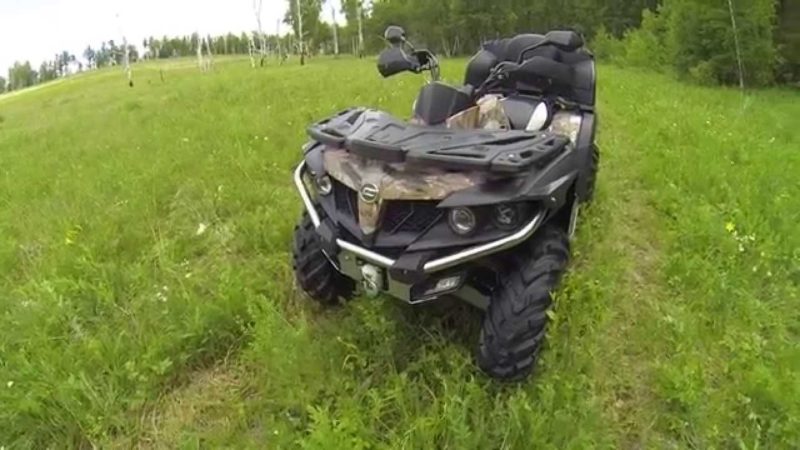
Дополнительными преимуществами квадроцикла СФ Мото X5 являются:
- Наличие вместительных багажных отделений сзади конструкции.
- Наличие пластиковой термозащитной накладки крышки вариатора.
- Наличие прочных алюминиевых рычагов передней и задней подвески.
- Наличие электрического усилителя рулевого механизма.
- Аккумуляторная батарея, устанавливаемая в этой модели, имеет 30 Ампер-часов.
- Фронтальные амортизационные стойки имеют пружины прогрессивной жесткости.
- Все приводы были оснащены пыльниками, изготовленными из эластичных и прочных материалов.
- Тормозная система была существенно модернизирована.
- На заднем карданом валу отсутствуют крестовины, вместо них выступают подвижные шлицевые соединения.
- На приборной панели отображаются все необходимые параметры о состоянии квадроцикла на текущий момент эксплуатации.
- Квадроцикл может быть дополнен быстросъемным сцепным устройством.
Технические характеристики
Силовая установка:
- Количество цилиндров — 1.
- Рабочий объем — 500 кубов.
- Номинальная мощность на выходе — 38 лошадиных сил/28 киловатт (при 6800 об/мин).
- Наибольший крутящий момент — 43 ньютона на метр (при 6000 об/мин).
- Количество распределительных валов — 1.
- Расположение распределительного вала — верхнее (SOHC).
- Количество клапанов — 4.
- Тип системы охлаждения — жидкостная.
- Тип системы смазки — масляный картер.
- Тип топливной системы — электронная система впрыска EFI.
- Рекомендуемое топливо — АИ-92.
- Тип системы зажигания — ECU.
- Тип системы запуска — электростартерная.
Шасси:
- Тип привода — полный.
- Тип трансмиссионной системы — вариатор с клиноременным приводом (CVT).
- Тип рамы — стальная трубчатая.
- Тип сцепления — центробежное автоматическое.
- Тип передней подвески — независимая с двойными поперечными A-образными рычагами и гидравлическими амортизаторами.
- Тип задней подвески — независимая с двойными поперечными H-образными рычагами и гидравлическими амортизаторами.
- Ход передней подвески — 170 миллиметров.
- Ход задней подвески — 225 миллиметров.
- Шины передних колес — AT26x9-12.
- Шины задних колес — AT26x11-12.
- Тип передних дисков — легкосплавные.
- Тип задних дисков — легкосплавные.
- Тип тормозной системы — двухконтурная, гидравлическая.
- Тип передних тормозов — гидравлические двухдисковые.
- Тип задних тормозов — однодисковый трансмиссионный.
- Тип стояночного тормоза — трансмиссионный.
Габаритные размеры:
- Конструкционная длина — 2350 миллиметров.
- Конструкционная ширина — 1160 миллиметров.
- Конструкционная высота — 1400 миллиметров.
- Высота по спинке сидения — 880 миллиметров.
- Длина колесной базы -1480 миллиметров.
- Наименьший дорожный просвет — 270 миллиметров.
- Наименьший радиус поворота — 4000 миллиметров.
Другие характеристики:
- Вместимость топливного резервуара — 18.5 литра.
- Максимальная развиваемая скорость передвижения — 90 километров в час.
- Максимальный вес перевозимого груза на переднем багажнике — 20 килограмм.
- Максимальный вес перевозимого груза на заднем багажнике — 40 килограмм.
- Снаряженный вес квадроцикла — 377 килограмм.
Цена
Квадроцикл CF MOTO X5 H.O. EPS в настоящее время находится в ценовом сегменте от 415 тысяч рублей и до 610 тысяч российских рублей. Цена изменяется в зависимости от года производства и комплектации. Стоит также отметить, что в стоимость добавляется утилизационный сбор, который для данной модели составляет 105 тысяч рублей.
Машина, бывшая в употреблении, сейчас обойдется по стоимости в районе от 260 тысяч рублей и до 470 тысяч российских рублей с учетом года выпуска, состояния и пробега на момент продажи.
Отзывы
- Недавно приобрел себе данный квадроцикл. Брал подержанный с пробегом в 1000 километров. Из дополнительного оснащения к нему досталась лишь защита. Обошелся он мне по стоимости в 335 тысяч рублей. Впервые прокатившись на нем, я получил массу положительных впечатлений (ранее была другая модель, и у нее по сравнению с этим было маловато мощности). Тяга на всем диапазоне просто отличная, при резком разгоне квадрик даже немного приседает. Пробовали ездить с пассажиром, так он дополнительный груз вообще не чувствует и также уверено берет разгон. Однако, заметил один недостаток, а именно люфтит руль вверх и вниз. Для интереса обратился к дилерам, так и там даже на новых машинах наблюдается похожая проблема. Создается ощущение, что рулевое управление болтается на карданном соединении, как будто не затянут.
- Такой квадроцикл использую для катания в лесу достаточно долгое время. За все это время эксплуатации серьезных поломок практически не случалось, хоть модель все же и требует некоторых доработок в технической части. До сих пор вызывает какие-то смутные чувства электроусилитель руля. Вроде бы он хорошо справляется со своей задачей, руки не устают, но с другой стороны он какой-то неинформативный. Но все же к этому, я думаю, привыкнуть можно. По сравнению с X8 на данный меньше летит грязи, то есть если тот при активной езде по бездорожью был практически полностью покрыт грязью, то у X5 еще остаются чистые участки. Вроде мелочь, но приятно.