- Manuals
- Brands
- Dräger Manuals
- Transmitter
- Polytron 8000
- Instructions for use manual
-
Contents
-
Table of Contents
-
Troubleshooting
-
Bookmarks
Quick Links
Dräger Polytron 8000
Instructions for Use
WARNING
!
Strictly follow the Instructions for Use.
The user must fully understand and strictly observe the
instructions. Use the product only for the purposes specified
in the Intended use section of this document.
i
Related Manuals for Dräger Polytron 8000
Summary of Contents for Dräger Polytron 8000
-
Page 1
Dräger Polytron 8000 Instructions for Use WARNING Strictly follow the Instructions for Use. The user must fully understand and strictly observe the instructions. Use the product only for the purposes specified in the Intended use section of this document. -
Page 3: Table Of Contents
13.1 Dräger Polytron 8000 ….. . . 34 Installation ……. .7 13.2…
-
Page 4: For Your Safety
Sections 1.5.5, 1.5.6 and 1.5.7 of Directive 94/9/EC is not covered at present. Exchanging components may compromise the intrinsic safety. This only applies if the device is intrinsically safe. Only operate the product within the framework of a risk- based alarm signaling concept. Dräger Polytron 8000…
-
Page 5: Description
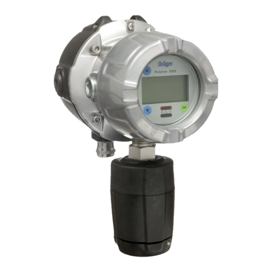
3 Enclosure with main electronics (and optional relay) 3 Enclosure with main electronics (and optional relay) 4 Lower part of housing 4 Lower part of housing 5 Sensor 5 Sensor 6 Assembled device 6 Feed through cable 7 e-Box 8 Assembled device Dräger Polytron 8000…
-
Page 6: Functional Description
Approvals Intended use The Dräger Polytron 8000 is an explosion-proof device for continuous monitoring of toxic gases or oxygen in the ambient air, corresponding to the integrated DrägerSensor. The housing…
-
Page 7: Installation
500 Ω for ≥ 16 V DC currents and environmental conditions. HART Multidrop 230 to 500 Ω When stranded conductors are used, an end ferrule must operation 11 to 30 V DC also be used. Dräger Polytron 8000…
-
Page 8: Mechanical Installation
(see chapter 4.6 on page 14). 4. Fit the plug back in the socket and tighten the screws. 5. Fit the enclosed protective cover over the plug and secure it with cable ties if necessary. Dräger Polytron 8000…
-
Page 9: Electrical Installation With E-Box
As soon as the installation is ready for commissioning, the device is connected to the NOTICE e-Box and put into operation. This prevents the device from being damaged during the construction phase. The EC sensing head is automatically recognized by the transmitter. Dräger Polytron 8000…
-
Page 10: Installation Of Ec Sensing Head Remote
The gas inlet area of the sensor must be protected from water, dust and mechanical damage and kept Connecting to the Polytron 8000 clear of dirt. Do not allow paint to block the gas inlet if painting is conducted in the area.
-
Page 11: Connecting The Device To A Dräger Control Unit
Installation 3.10 Connecting the device to a Dräger 3.13 Installing software dongles control unit The following SW dongles are available for the Polytron 8000: Sensor test dongle Activates the sensor test NOTICE 83 17 619 (for certain sensors only) Information on connection can be found in the…
-
Page 12: Operation
For functions that can be selected and activated, the activation is initiated by touching » «. List closed above / complete There are no further functions, menus or sub-menus listed above. List can be scrolled upwards There are further functions, menus or sub-menus listed above. Dräger Polytron 8000…
-
Page 13: Activating The Info Mode
A1 Alarm limit and measurement units the LED stops flashing and is lit continuously instead until A2 Alarm limit and measurement units the alarm condition is no longer present. The corresponding relay is deactivated. 1 Only displayed when relay is configured. Dräger Polytron 8000…
-
Page 14: Switching To The Quick Menu Mode
This conforms to the NAMUR NE43 recommendation. The 4 to 20 mA interface on the device can be customized and configured to individual requirements. The device is provided with suitable standard settings factory default (see chapter 12.3 on page 32). Dräger Polytron 8000…
-
Page 15: Calibration
1. Select Calibration > Zero Calibration and confirm. The Maintenance signal is transmitted. The message Apply zero gas appears. 2. Apply zero gas (synthetic air or nitrogen) to the sensor. 3. Select Next and confirm. The current measured value is displayed. Dräger Polytron 8000…
-
Page 16: Performing Auto Calibration
6. When the value is stable, shut off the test gas and wait until the measurement is below any possible alarm thresholds again. The calibration is performed again with Redo. Complete the calibration with Accept value The device returns to the measurement mode. Dräger Polytron 8000…
-
Page 17: Menu Overview
Calibration interval Maintenance signal page 24 page 23 Set sensor test Maintenance current page 23 Analog offset page 23 Set current signal page 23 Set concentr. page 23 Set fault page 23 Set warning page 24 Set mainten. Dräger Polytron 8000…
-
Page 18: Information Menu
Select Information > Instrument > Modules and confirm. A list of all possible modules is displayed. The installed modules are identified by a , those not installed by a Mark a module and request detailed information with Dräger Polytron 8000…
-
Page 19: Settings Menu
If the alarm is inactive, the alarm state will not be The settings for the A1 alarm are now complete. issued by the LEDs or the relay interface! A warning message will be shown on the display! Dräger Polytron 8000…
-
Page 20
NOTICE When the function Set fault is exited in the menu, Latching and The alarm must be acknowledged the Polytron 8000 reverts automatically to measurement acknowledgeable manually. The alarm can be mode. acknowledged when the alarm condition is still present. -
Page 21: Communication Settings
Changing the display mode The display of measured values can be turned on or off with this function. 1. Select Settings > Instrument > Display > Display mode and confirm. 2. Select Standard or Non display and confirm. Dräger Polytron 8000…
-
Page 22
This function sets the type of signal used on the analog 4. Select Confirm and confirm. interface for the maintenance signal. 1. Select Settings > Communication > Analog interface > Maint. signal and confirm. 2. Select static or dynamic signal type and confirm. Dräger Polytron 8000… -
Page 23
2. Select On or Off and confirm. The current for the warning signal will be transmitted on the Alarms in the central controller may be triggered by these functions! If necessary, the alarms in the central analog interface. controller must be disabled beforehand. Dräger Polytron 8000… -
Page 24: Sensor Settings
4. Set the full scale reading and confirm. The setting for the full scale reading is displayed. 5. Select Next and confirm. an overview of the new gas settings is displayed. Return to the previous view with Previous or confirm the settings with Confirm. Dräger Polytron 8000…
-
Page 25
Settings menu Information about measurement units The Polytron 8000 represents the measured value in various optional units. The following are available: ubar ug/L vol. % mbar ug/m %LEL mg/L uL/L %LIE mg/m uL/m %UEG mL/L mL/m The Polytron 8000 automatically calculates the correct value. -
Page 26: Datalogger
The average value of all the concentrations measured within the selected sampling time is stored. 8.5.3 Clearing the datalogger 1. Select Settings > Datalogger > Clear Datalogr. and confirm. 2. To clear the datalogger, select Confirm and confirm. Dräger Polytron 8000…
-
Page 27: Troubleshooting
Have the device checked by DrägerService. #105 Device fault. Have the device checked by DrägerService. #137 Device fault. Restart. If this fault occurs again: Have device checked by DrägerService. ® DrägerService is a registered trademark of Dräger. Dräger Polytron 8000…
-
Page 28: Warning Reference
Enable alarms (see chapter 8.2.1 on page 19). #164 Sensor warm-up phase has not ended yet. Wait until the sensor has warmed up. #165 Increased measurement error must be expected. #167 Calibration interval expired. Recalibrate the device (see chapter 5.1 on page 15). #170 Dräger Polytron 8000…
-
Page 29: Maintenance
(gas type, measurement range, test gas, calibration interval). Otherwise the preset values of the sensor (see Instructions for Use for the sensor) are uploaded from the transmitter if the sensor lock function (see chapter 8.4.4 on page 24) is deactivated. Dräger Polytron 8000…
-
Page 30: Changing The Main Electronics
Danger of explosions! Do not dispose of in fire, risk of chemical burns! Do not open with force. Observe the applicable local waste disposal regulations. For information consult your local environmental agency, local government offices or appropriate waste disposal companies. Dräger Polytron 8000…
-
Page 31: Technical Data
Specifications for the sensor: see sensor data sheet Pressure 700 to 1300 hPa (20.7 to 38.4 in. Hg) Humidity 0 to 100 % R. H., non-condensing Temperature –40 to +65 °C (–40 to 149 °F) Environmental influences See respective sensor data sheets. Dräger Polytron 8000…
-
Page 32: Torques
Technical data 12.1 Torques 12.3 Factory settings (The torques are valid for the aluminum and stainless steel 12.3.1 Alterable settings for the Polytron 8000 316 variants) Menu Standard setting Part Torque Lb. In. Torque Nm A1 Alarm Housing cover min. 266 min.
-
Page 33
A2 is not and the gas concentration is so high that A1 and A2 are triggered, an acknowledgement results in the A1 relay dropping out. However the red LED continues to give double flashes as long as the A2 condition exists. Dräger Polytron 8000… -
Page 34: Order List
68 12 695 Dräger Polytron 8000 EC d A 4-20/HART 4544403 IR connection kit, 5000/8000 45 44 197 Dräger Polytron 8000 EC d A 4-20/HART relay 4544404 Dräger PolySoft 8000 83 23 406 Dräger PolySoft 8000 Premium 83 23 412 Dräger Polytron 8000 EC d S 4-20/HART…
-
Page 35: Declaration Of Conformity
Declaration of conformity Declaration of conformity Dräger Polytron 8000…
-
Page 36: Dräger Polytron
Dräger Polytron 8000…
-
Page 37
Dräger Polytron 8000…
(Ocr-Read Summary of Contents of some pages of the Dräger Polytron 8000 Document (Main Content), UPD: 03 May 2023)
-
11, Installation Dräger Polytron 8000 11 3.10 Connecting the device to a Dräger control unit Electrical connections to the control unit z Connect the screen for the wires to the grounding point in the control unit (e.g., chassis, grounding rail). 3.11 Connecting the device to a PC The separately available Polytron 5000/8000 IR connection kit is intended for use with the Polytron 5000/8000 and enables communication between the Polytron 5000/8000 and a PC. 3.12 PolySoft 800…
-
19, Dräger Polytron 8000 Settings menu Dräger Polytron 8000 19 8 Settings menu This menu contains all the functions that are required for the individual configuration of the device. 8.1 Switching SIL lock on or off With this function, the device can be protected against unauthorized changes to the configuration with a password. Changing the configuration (e.g., changing the measurement range from 100 ppm to 50 ppm) will cause the device to displ…
-
4, 4 Dräger Polytron 8000 For your safety 1 For your safety 1.1 General safety instructions z Before using the product, carefully read the Instructions for Use. z Strictly follow the Instructions for Use. The user must fully understand and strictly observe the instructions. Use the product only for the purposes specified in the Intended use section of this document. z Do not dispose of the Instructions for Use. Ensure tha…
-
16, 16 Dräger Polytron 8000 Calibration After the displayed value is stable: 4. Confirm with OK. The message Please wait… appears. The actual value is displayed. z Actual value within the permissible range: { Select Next and confirm. { Shut off the test gas and remove the calibration adapter from the sensor or disconnect the hose. 5.1.2 Span calibration 1. Select Calibration > Span calibration and confirm. The parameters of the selected test gas are…
-
25, Settings menu Dräger Polytron 8000 25 Information about measurement units The Polytron 8000 represents the measured value in various optional units. The following are available: The Polytron 8000 automatically calculates the correct value. Information about the 20 mA measuring range The maximum range can be set with this function. At the maximum range set, the device outputs 20 mA on the 4-20 mA interface. 8.4.6 …
-
10, Dräger Polytron 8000 10 Dräger Polytron 8000 Installation 3.8 Installation of EC sensing head remote 3.8.1 Wall-pipe mounting set 1. Install wall-pipe mount (8) as specified by the assembly instructions. 2. Screw the EC sensing head to the wall mount with the included screw and washer (6). 3. Select the appropriate protection cap (7) and place on the screw. 3.8.2 Installing sensor 1. Unscrew bayonet ring (3) from EC sensing head and remove blank. 2. Remove sensor from p…
-
18, 18 Dräger Polytron 8000 Information menu 7 Information menu Specific data about the device, the sensor used and the target gas are summarized in this menu. The menu can be accessed without a password. Changes to the data are not possible. 7.1 Device settings 7.1.1 Displaying warning messages To display warnings in plain text with warning numbers, see chapter 9 on page 27. The symbol is displayed …
-
13, Operation Dräger Polytron 8000 13 4.2.1 Special symbols The following special symbols, which indicate the device state, may be displayed on the right hand side in measurement mode. 4.2.2 LED symbols When the optional relay PCB is used: z If the first alarm has been triggered, the red LED will single flash. A1 relay is activated. z If the second alarm has been triggered, the red LED will double flash. A2 relay is activated. z If an alarm can be acknowledged and is ackn…
-
9, Dräger Polytron 8000 Installation Dräger Polytron 8000 9 Connections for 9-way plug (relays): (NO = Normally open, NC = Normally closed, C = Common) 3.6 Electrical installation with e-Box z Install the e-Box in accordance with the Installation Instructions for the Polytron 5000/8000 e-Box (order no. 90 33 242). 3.7 Installing sensor 1. Unscrew bayonet ring (3) and remove blank. 2. Remove sensor from packaging. 3. Insert sensor or MEC sensor adapter (4) into the o…
-
1, WARNING Strictly follow the Instructions for Use. The user must fully understand and strictly observe the instructions. Use the product only for the purposes specified in the Intended use section of this document. ! Dräger Polytron 8000 Instructions for Use i
… -
32, 32 Dräger Polytron 8000 Technical data 12.1 Torques (The torques are valid for the aluminum and stainless steel 316 variants) If an optional e-Box is being used, fasten the device securely to the e-Box with 4 screws and a tightening torque of 8 Nm. 12.2 Tightening torque and cable size for field wiring terminals 12.3 Factory settings 12.3.1 Alterable settings for the Polytron 8000 Part Torque Lb. In. Torque Nm Housing cover min. 266 min. 30 Sensors min. 266 min. …
-
33, Technical data Dräger Polytron 8000 33 12.3.2 Unchangeable settings Fault Meaning Fault relay / wired in e-Box Energized / NO Yellow Fault LED Lights when a fault is present (see chapter 9 on page 27). Red Alarm LED Gives single flashes when an A1 alarm is present. Gives double flashes when an A2 alarm is present. If an alarm is configured as acknowledgeable and the alarm is acknowledged, the LED lights. Alarm hierarchy…
-
7, Installation Dräger Polytron 8000 7 3 Installation 3.1 General information for the installation The selection of a suitable mounting location is crucial for the effectiveness and performance of the entire system. Every detail of the installation must be thoroughly thought out. The following must be noted in particular: z The local and national rules and regulations for the installation of gas measur…
-
22, 22 Dräger Polytron 8000 Settings menu Displaying the Unique Identifier This function enables reading of the Unique Identifier (unique HART address), which has to be known for almost all the HART addressing commands. However this information is only required for those systems that are not able to read back the Unique Identifier using HART command #0 in Short-Frame Format or HART command #11. The display corresp…
-
12, 12 Dräger Polytron 8000 Operation 4 Operation 4.1 Operating fundamentals 4.1.1 Menu navigation It is possible to scroll through he menu items by tapping the and symbols with the magnetic wand (Part Number 4544101, blue). confirms a function. Graphic symbols facilitate navigation in the various menus. 4.1.2 Changing parameter values or the parameter status 1. Select the desired menu item with and . 2. Confirm the menu item …
-
27, Troubleshooting Dräger Polytron 8000 27 9 Troubleshooting 9.1 Fault reference Fault number Cause Remedy #001 #003 #004 #005 #011 — #014 #020 — #024 #043 #060 #067 Serious device fault, various causes. Have the device checked by DrägerService ®1 . #002 #025 — #027 #030 — #034 #041 #042 #044 #050 #052 #081 #085 Serious data error in the device, various causes. Reset the device to factory settings (see chapter 8.2.6 …
Table of Contents for Dräger Polytron 8000:
-
Installation Dräger Polytron 8000 9 Connections for 9-way plug (relays): (NO = Normally open, NC = Normally closed, C = Common) 3.6 Electrical installation with e-Box z Install the e-Box in accordance with the Installation Instructions for the Polytron 5000/8000 e-Box (order no. 90 33 242). 3.7 Installing sensor 1. Unscrew bayonet ring (3) and remove blank. 2. Remove sensor from packaging. 3. Insert sensor or MEC sensor adapter (4) into the opening. The Dräger label on the sensor must point to the mark on the sensing head housing (5). 4. Lock sensor with bayone
-
16 Dräger Polytron 8000 Calibration After the displayed value is stable: 4. Confirm with OK. The message Please wait… appears. The actual value is displayed. z Actual value within the permissible range: { Select Next and confirm. { Shut off the test gas and remove the calibration adapter from the sensor or disconnect the hose. 5.1.2 Span calibration 1. Select Calibration > Span calibration and confirm. The parameters of the selected test gas are displayed. Examp
-
18 Dräger Polytron 8000 Information menu 7 Information menu Specific data about the device, the sensor used and the target gas are summarized in this menu. The menu can be accessed without a password. Changes to the data are not possible. 7.1 Device settings 7.1.1 Displaying warning messages To display warnings in plain text with warning numbers, see chapter 9 on page 27. The symbol is displayed when there is a warning present. z Select Information > Instrument > Warnings and confirm. Warnings are displayed in plain text. If several warnings are
-
Technical data Dräger Polytron 8000 33 12.3.2 Unchangeable settings Fault Meaning Fault relay / wired in e-Box Energized / NO Yellow Fault LED Lights when a fault is present (see chapter 9 on page 27). Red Alarm LED Gives single flashes when an A1 alarm is present. Gives double flashes when an A2 alarm is present. If an alarm is configured as acknowledgeable and
-
26 Dräger Polytron 8000 Settings menu 8.5 Datalogger The datalogger has a storage capacity of approx. 3000 measurements. At a sampling interval of 1 minute, this would allow monitoring for approx. 50 hours. The monitoring time can be significantly increased if the Trigger function is enabled. The results in the datalogger can only be evaluated with the PolySoft 8000 PC software. An
-
12 Dräger Polytron 8000 Operation 4 Operation 4.1 Operating fundamentals 4.1.1 Menu navigation It is possible to scroll through he menu items by tapping the and symbols with the magnetic wand (Part Number 4544101, blue). confirms a function. Graphic symbols facilitate navigation in the various menus. 4.1.2 Changing parameter values or the parameter status 1. Select the desired menu item with and . 2. Confirm the menu item with . The current value or status will be displayed. 3. Using and , the value of a numerical parameter can be c
-
6 Dräger Polytron 8000 Description 2.2 Functional description 2.2.1 Principle of operation of the DrägerSensor ® 1 EC The electrochemical DrägerSensor EC are electrochemical transducers for measuring the partial pressure of a gas under atmospheric conditions. The ambient air diffuses through a membrane in the liquid electrolyte of the sensor. A measuring electrode, a counter- electrode and a reference electrode are in the electrolyte. An electronic potentiostat circuit maintains a constant electrical voltage between the measuring electr
-
Declaration of conformity Dräger Polytron 8000 35 14 Declaration of conformity
-
Installation Dräger Polytron 8000 11 3.10 Connecting the device to a Dräger control unit Electrical connections to the control unit z Connect the screen for the wires to the grounding point in the control unit (e.g., chassis, grounding rail). 3.11 Connecting the device to a PC The separately available Polytron 5000/8000 IR connection kit is intended for use with the Polytron 5000/8000 and enables communication between the Polytron 5000/8000 and a PC. 3.
Questions, Opinions and Exploitation Impressions:
You can ask a question, express your opinion or share our experience of Dräger Polytron 8000 device using right now.
 |
[Page 1] Dräger Polytron 8000 WARNING Strictly follow the Instructions for Use. The user must fully understand and strictly observe the instructions. Use the product only for the purposes specified in the Intended use section of this document. ! Dräger Polytron 8000 Instructio… |
 |
[Page 2] Dräger Polytron 8000 … |
 |
[Page 3] Dräger Polytron 8000 Contents Dräger Polytron 8000 3 Contents 1 For your safety . . . . . . . . . . . . . . . . . . . . . . . . . . . . .4 1.1 General safety instructions . . . . . . . . . . . . . . . . . . . .4 1.2 Definitions of alert icons. . . . . . . . . . . . . …. |
 |
[Page 4] Dräger Polytron 8000 4 Dräger Polytron 8000 For your safety 1 For your safety 1.1 General safety instructions z Before using the product, carefully read the Instructions for Use. z Strictly follow the Instructions for Use. The user must fully understand and strictly obs… |
 |
[Page 5] Dräger Polytron 8000 Description Dräger Polytron 8000 5 2 Description 2.1 Product overview 2.1.1 Explosion proof device 1 Housing cover 2 Handle 3 Enclosure with main electronics (and optional relay) 4 Lower part of housing 5 Sensor 6 Assembled device 2.1.2 Explosion pr… |
 |
[Page 6] Dräger Polytron 8000 6 Dräger Polytron 8000 Description 2.2 Functional description 2.2.1 Principle of operation of the DrägerSensor ® 1 EC The electrochemical DrägerSensor EC are electrochemical transducers for measuring the partial pressure of a gas under atmosphe… |
 |
[Page 7] Dräger Polytron 8000 Installation Dräger Polytron 8000 7 3 Installation 3.1 General information for the installation The selection of a suitable mounting location is crucial for the effectiveness and performance of the entire system. Every detail of the installation mus… |
 |
[Page 8] Dräger Polytron 8000 8 Dräger Polytron 8000 Installation 3.4 Mechanical installation z Use the supplied drilling template for mounting on a wall. z The mounting surface should be even and free of sharp edges. z Dräger recommends using M6 Allen bolts. z The openings mus… |
 |
[Page 9] Dräger Polytron 8000 Installation Dräger Polytron 8000 9 Connections for 9-way plug (relays): (NO = Normally open, NC = Normally closed, C = Common) 3.6 Electrical installation with e-Box z Install the e-Box in accordance with the Installation Instructions for the Polyt… |
 |
[Page 10] Dräger Polytron 8000 10 Dräger Polytron 8000 Installation 3.8 Installation of EC sensing head remote 3.8.1 Wall-pipe mounting set 1. Install wall-pipe mount (8) as specified by the assembly instructions. 2. Screw the EC sensing head to the wall mount with the included s… |
 |
[Page 11] Dräger Polytron 8000 Installation Dräger Polytron 8000 11 3.10 Connecting the device to a Dräger control unit Electrical connections to the control unit z Connect the screen for the wires to the grounding point in the control unit (e.g., chassis, grounding rail). 3.11… |
 |
[Page 12] Dräger Polytron 8000 12 Dräger Polytron 8000 Operation 4 Operation 4.1 Operating fundamentals 4.1.1 Menu navigation It is possible to scroll through he menu items by tapping the and symbols with the magnetic wand (Part Number 4544101, blue). confirms a function. Gr… |
 |
[Page 13] Dräger Polytron 8000 Operation Dräger Polytron 8000 13 4.2.1 Special symbols The following special symbols, which indicate the device state, may be displayed on the right hand side in measurement mode. 4.2.2 LED symbols When the optional relay PCB is used: z If the firs… |
 |
[Page 14] Dräger Polytron 8000 14 Dräger Polytron 8000 Operation 4.4 Switching to the Quick Menu mode z Tap and hold for 1 to 2 seconds. The Quick Menu will open. This menu is displayed without any password request. No changes can be made. The selected information about status … |
 |
[Page 15] Dräger Polytron 8000 Calibration Dräger Polytron 8000 15 5 Calibration Repeat the calibration of the device at regular intervals as specified in the respective sensor data sheet. 5.1 Calibrating the device 1. Connect the pressure regulator to the test gas cylinder. 2. A… |
 |
[Page 16] Dräger Polytron 8000 16 Dräger Polytron 8000 Calibration After the displayed value is stable: 4. Confirm with OK. The message Please wait… appears. The actual value is displayed. z Actual value within the permissible range: { Select Next and confirm. { Shut off the te… |
 |
[Page 17] Dräger Polytron 8000 Menu overview Dräger Polytron 8000 17 6 Menu overview ◄ Back to measuring Information page 18 Instrument page 18 Warnings page 18 Sensor page 18 Faults page 18 Calibration page 15 Data logger page 18 Device codes page 18 Modules page 18 Setti… |
 |
[Page 18] Dräger Polytron 8000 18 Dräger Polytron 8000 Information menu 7 Information menu Specific data about the device, the sensor used and the target gas are summarized in this menu. The menu can be accessed without a password. Changes to the data are not possible. 7.1 Device… |
 |
[Page 19] Dräger Polytron 8000 Settings menu Dräger Polytron 8000 19 8 Settings menu This menu contains all the functions that are required for the individual configuration of the device. 8.1 Switching SIL lock on or off With this function, the device can be protected against una… |
 |
[Page 20] Dräger Polytron 8000 20 Dräger Polytron 8000 Settings menu The functional relationship between the various settings is explained in the following table: Testing Alarm A1 This function simulates the A1 alarm status. 1. Select Settings > Instrument > Alarm > Set … |
 |
[Page 21] Dräger Polytron 8000 Settings menu Dräger Polytron 8000 21 Selection options: 8.2.6 Resetting the device to factory settings The following device parameters are reset to the factory settings with this function (see chapter 12.3 on page 32). z Alarm parameters z Password… |
 |
[Page 22] Dräger Polytron 8000 22 Dräger Polytron 8000 Settings menu Displaying the Unique Identifier This function enables reading of the Unique Identifier (unique HART address), which has to be known for almost all the HART addressing commands. However this information is only … |
 |
[Page 23] Dräger Polytron 8000 Settings menu Dräger Polytron 8000 23 Setting the maintenance current This function is used to set the current for the maintenance signal on the analog interface. 1. Select Settings > Communication > Analog interface > Maint. current and co… |
 |
[Page 24] Dräger Polytron 8000 24 Dräger Polytron 8000 Settings menu Testing the maintenance signal This function is used to set the analog interface for the maintenance signal. 1. Select Settings > Communication > Analog interface > Set mainten. and confirm. 2. Select … |
 |
[Page 25] Dräger Polytron 8000 Settings menu Dräger Polytron 8000 25 Information about measurement units The Polytron 8000 represents the measured value in various optional units. The following are available: The Polytron 8000 automatically calculates the correct value. Informati… |
 |
[Page 26] Dräger Polytron 8000 26 Dräger Polytron 8000 Settings menu 8.5 Datalogger The datalogger has a storage capacity of approx. 3000 measurements. At a sampling interval of 1 minute, this would allow monitoring for approx. 50 hours. The monitoring time can be significantly i… |
 |
[Page 27] Dräger Polytron 8000 Troubleshooting Dräger Polytron 8000 27 9 Troubleshooting 9.1 Fault reference Fault number Cause Remedy #001 #003 #004 #005 #011 — #014 #020 — #024 #043 #060 #067 Serious device fault, various causes. Have the device checked by DrägerService ®1 . … |
 |
[Page 28] Dräger Polytron 8000 28 Dräger Polytron 8000 Troubleshooting 9.2 Warning reference Warning number Cause Remedy #101 Datalogger in Stack mode is 100 % full and is not logging any more data. Read out the data, clear the datalogger and start again. #102 Datalogger in Sta… |
 |
[Page 29] Dräger Polytron 8000 Maintenance Dräger Polytron 8000 29 10 Maintenance 10.1 Maintenance intervals 10.1.1 During commissioning z Check calibration. z Check signal transmission to controller and triggering of alarms. 10.1.2 Every 6 months z Inspection by trained service … |
 |
[Page 30] Dräger Polytron 8000 30 Dräger Polytron 8000 Disposal 10.3 Changing the main electronics 1. Switch off the power to the device or declassify the area according to the local regulations. 2. Loosen the set screw and unscrew the housing cover from the device. 3. Lift the h… |
 |
[Page 31] Dräger Polytron 8000 Technical data Dräger Polytron 8000 31 12 Technical data CAUTION Specifications and restrictions in the Instructions for Use and/or data sheets for the sensors used must be observed. For SIL applications the Dräger Polytron 8X00 Safety Manual must… |
 |
[Page 32] Dräger Polytron 8000 32 Dräger Polytron 8000 Technical data 12.1 Torques (The torques are valid for the aluminum and stainless steel 316 variants) If an optional e-Box is being used, fasten the device securely to the e-Box with 4 screws and a tightening torque of 8 Nm. … |
 |
[Page 33] Dräger Polytron 8000 Technical data Dräger Polytron 8000 33 12.3.2 Unchangeable settings Fault Meaning Fault relay / wired in e-Box Energized / NO Yellow Fault LED Lights when a fault is present (see chapter 9 on page 27). Red Alarm LED Gives single flashes when an A1… |
 |
[Page 34] Dräger Polytron 8000 34 Dräger Polytron 8000 Order list 13 Order list 13.1 Dräger Polytron 8000 13.2 Accessories 13.3 Replacement parts Name and description Order Number Dräger Polytron 8000 EC d A 4-20/HART 4544403 Dräger Polytron 8000 EC d A 4-20/HART relay 454440… |
 |
[Page 35] Dräger Polytron 8000 Declaration of conformity Dräger Polytron 8000 35 14 Declaration of conformity |
 |
[Page 36] Dräger Polytron 8000 36 Dräger Polytron 8000 15 |
 |
[Page 37] Dräger Polytron 8000 www.norrscope.co m Dräger Polytron 8000 37 |
| Document’s Content and Additional Information | Share Manual |
|---|---|
|
Dräger Polytron 8000 User manual manual
Pages Preview: Document Transcription:
See Details |


