
-
Contents
-
Table of Contents
-
Troubleshooting
-
Bookmarks
Quick Links
Operating Instructions –HOME MEDIA GALLERY–
Manual de instrucciones –HOME MEDIA GALLERY–
–HOME MEDIA GALLERY–
AUDIO/VIDEO MULTI-CHANNEL RECEIVER
RECEPTOR MULTICANAL DE AUDIO/VÍDEO
Related Manuals for Pioneer VSX-LX70
Summary of Contents for Pioneer VSX-LX70
-
Page 1
Operating Instructions –HOME MEDIA GALLERY– Manual de instrucciones –HOME MEDIA GALLERY– –HOME MEDIA GALLERY– AUDIO/VIDEO MULTI-CHANNEL RECEIVER RECEPTOR MULTICANAL DE AUDIO/VÍDEO… -
Page 2: Features Of Home Media Gallery
You can select and listen to your favorite Internet radio station from the list of Internet radio stations created, edited, and managed by the vTuner database service exclusively for use with the Pioneer products. Also, you can listen to Internet radio station managed by Neural THX.
-
Page 3: Connecting To The Network Through Lan Interface
FAT16/32. It is not possible to connect this unit to a personal computer for USB playback. • Pioneer cannot guarantee compatibility (operation and/or bus power) with all USB mass storage devices and assumes no responsibility for any loss of…
-
Page 4: Playback With Home Media Gallery
Playback with Home Media Gallery Chapter 3: Playback with Home Media Gallery DLNA Introduction The Home Media Gallery allows you to play music on media servers connected on an identical Local Area Network (LAN) as the receiver. This unit allows for the playing of files stored on the following: •…
-
Page 5: About Playback Behavior Over A Network
TUNE PROGRAM RECEIVER TV CONTROL Pioneer is not responsible for any malfunction of the player and/or the Home Media Gallery features due to communication error/malfunctions associated with your Important network connection and/or your PC, or other connected •…
-
Page 6: Playing Back Audio Files Stored On Components On The Network
Playback with Home Media Gallery Press HOME MEDIA GALLERY (press iPod while Repeat Step 3 to play back the desired song. you press and hold SHIFT ) to select HMG as the input You can perform the following operations with the remote control of this receiver.
-
Page 7: Listening To Internet Radio Stations
Playback with Home Media Gallery Listening to Internet radio stations Listening to Neural Music Direct About Internet radio About Neural Music Direct Internet radio is an audio broadcasting service Neural Music Direct is an Internet radio station managed transmitted via the Internet. There are a large number of and operated by Neural THX.
-
Page 8: About Playable File Formats
Playback with Home Media Gallery About playable file formats The Home Media Gallery feature of this receiver supports the following file formats. Note that some file formats are not available for playback although they are listed as playable file formats. Also, the compatibility of file formats varies depending on the type of server.
-
Page 9: Advanced Operations For Internet Radio
Playback with Home Media Gallery Retrieving saved Internet radio stations Advanced operations for Internet radio You need to save Internet radio stations first before retrieving them. If there are no Internet radio stations currently being saved, see Saving Internet radio stations above and save at least one Internet radio station before D.ACCESS CLASS…
-
Page 10: Setting Up The Network
Setup Chapter 4: Setup Setting up the network • Press or the numeric buttons to enter In case the router connected to the LAN terminal on this alphanumeric characters. To delete alphanumeric receiver is a broadband router (with the built-in DHCP characters entered one at a time, press server function), simply turn on the DHCP server CLEAR.
-
Page 11
Setup Select ‘ Network Setup ’ and press ENTER to confirm 10 Select ‘ Change ’ and press ENTER to confirm your your selection. selection. The ‘Network Connection’ screen appears. The ‘Edit Gateway’ screen appears. Either ‘ Network Found ’ or ‘ No Network Found ’ H o me Me di a G — 5 5 . -
Page 12: Checking The Network Settings
Setup 17 Select ‘ Change ’ and press ENTER to confirm your Checking the network settings selection. You can check the following network settings of this The ‘Edit Proxy Hostname’ screen appears. receiver: the MAC address, the IP address, the gateway IP address, the proxy server, the Subnet mask, and the H om e Medi a G — 55 .
-
Page 13: Additional Information
Also, the cause of a problem may lie elsewhere other than this receiver. Check your audio components on the network as well as your USB memory device. If problems persist or if the following information does not provide you with an appropriate remedy, consult with your nearest Pioneer service center. Symptoms…
-
Page 14
Additional information Symptoms Causes Remedies Refer to Audio playback is The audio file currently being played back was Check whether the audio file was recorded in a undesirably stopped or not recorded in a format playable on this format supported by this receiver. disturbed. -
Page 15: About Status Messages
Additional information About status messages Refer to the following information when you come up with a status message while operating the Home Media Gallery. Status messages Descriptions Please Wait A component on the network, including a PC, is currently being connected. Wait for a while. Connection Down The selected category or Internet radio station cannot be accessed.
-
Page 16
Additional information Glossary LAN is an abbreviation for the Local Area Network, which is a computer network covering a small geographical area, like a home, office, or group of buildings. Current Default Gateway LANs are most likely to be based on switched IEEE 802.3 Default Gateway is a node on a computer network that Ethernet technology, running at 10, 100, or 1000 Mbit/s, serves as an access point to another network. -
Page 17: About Flac
Additional information Windows Media About FLAC Windows Media is a multimedia framework for media creation and distribution for Microsoft Windows. Windows Media is either a registered trademark or FLAC Decoder trademark of Microsoft Corporation in the U.S. and/or Copyright © 2000, 2001, 2002, 2003, 2004, 2005, 2006, other countries.
-
Page 18: Características De Home Media Gallery
Internet favorita que se encuentra en la lista de emisoras de radio de Internet creada, editada y administrada por el servicio de base de datos vTuner para uso exclusivo con productos Pioneer. También puede escuchar emisoras de radio de Internet administradas por Neural THX.
-
Page 19: Uso De La Interfaz Usb
USB. • Pioneer no puede garantizar la compatibilidad (funcionamiento y/o alimentación de bus) con todos los dispositivos de almacenamiento de gran capacidad USB, y no asume ninguna responsabilidad por ninguna pérdida de datos que pueda ocurrir cuando se hagan conexiones a este receptor.
-
Page 20: Reproducción Con Home Media Gallery
Capítulo 3: Reproducción con Home Media Gallery DLNA Introducción Home Media Gallery le permite reproducir música en servidores de medios conectados a un Área de Red Local (LAN) idéntica a la que está conectado el receptor. Esta unidad permite reproducir los archivos guardados en lo siguiente: DLNA CERTIFIED™…
-
Page 21
PC conectado y del ajuste de tal software puede RECEIVER TV CONTROL que la conexión de red se bloquee. Pioneer no se hace responsable de ningún fallo de Importante funcionamiento del reproductor o de Home Media Gallery debido a errores de comunicación/fallos de •… -
Page 22
Pulse HOME MEDIA GALLERY (pulse iPod mientras Repita el paso 3 para reproducir la canción deseada. mantiene pulsado SHIFT) para seleccionar HMG como Con el mando a distancia de este receptor puede realizar las fuente de entrada. operaciones siguientes. Note que, dependiendo de la categoría que esté… -
Page 23
Recepción de emisoras de radio de Internet Recepción de Neural Music Direct Acerca de la radio de Internet Acerca de Neural Music Direct La radio de Internet es un servicio de emisión de audio a Neural Music Direct es una emisora de radio de Internet través de Internet. -
Page 24
Acerca de los formatos de archivo reproducibles La característica Home Media Gallery de este receptor soporta los formatos de archivo siguientes. Note que algunos formatos de archivo no podrán reproducirse aunque estén en la lista de formatos de archivo reproducibles. Además, la compatibilidad de formatos de archivo cambia dependiendo del tipo de servidor. -
Page 25: Operaciones Avanzadas Para Radio De Internet
Recuperación de las emisoras de radio de Operaciones avanzadas para radio de Internet guardadas Antes de recuperar las emisoras de radio de Internet Internet tiene que guardarlas. Si no hay actualmente emisoras de radio de Internet guardadas, consulte Para guardar emisoras de radio de Internet más arriba y guarde al D.ACCESS CLASS…
-
Page 26: Configuración De La Red
Capítulo 4: Configuración Sugerencia Configuración de la red • Pulse / o los botones numéricos para introducir En el caso de que el enrutador conectado al terminal LAN caracteres alfanuméricos. Para eliminar uno a uno de este receptor sea de banda ancha (con función de caracteres introducidos, pulse …
-
Page 27
Seleccione ‘Network Setup’ y pulse ENTER para 10 Seleccione ‘Change’ y pulse ENTER para confirmar confirmar su elección. su elección. Aparece la pantalla ‘Network Connection’. Aparece la pantalla ‘Edit Gateway’. Aparece ‘Network Found’ o ‘No Network Found’. Home Media G — 55 .0dB Home Me di a G — 5 5.0dB… -
Page 28
17 Seleccione ‘Change’ y pulse ENTER para confirmar Comprobación de los ajustes de la red su elección. Puede comprobar los ajustes de red siguientes de este Aparece la pantalla ‘Edit Proxy Hostname’. receptor: las direcciones MAC, IP e IP de puerta de enlace, el servidor proxy, la máscara de subred y la Hom e M edia G — 55 .0dB… -
Page 29: Información Adicional
Además, la causa de un problema puede encontrarse en otro lugar que no sea este receptor. Verifique sus componentes de audio de la red y también su dispositivo de memoria USB. Si los problemas persisten, o si la información siguiente no le proporciona un remedio apropiado, consulte en su centro de servicios Pioneer más cercano.
-
Page 30
Síntomas Causas Soluciones Consulte La reproducción de audio se El archivo de audio que está siendo reproducido Compruebe si el archivo de audio fue grabado en detiene sin querer o se no fue grabado en un formato que pueda un formato compatible con este receptor. altera. -
Page 31: Acerca De Los Mensajes De Estado
Acerca de los mensajes de estado Consulte la información siguiente si surge algún mensaje de estado mientras utiliza Home Media Gallery. Mensajes de estado Descripciones Please Wait Un componente de la red, incluyendo un PC, está siendo conectado. Espere un poco. Connection Down No se puede acceder a la categoría o emisora de radio de Internet seleccionada.
-
Page 32
Glosario LAN son las siglas de Local Area Network (área de red local), que es una red de computadoras que cubre una pequeña zona geográfica, como un hogar, una oficina o Puerta de enlace predeterminada un grupo de edificios. Las LAN actuales se basan lo más La puerta de enlace predeterminada es un nodo en una probable en la tecnología Ethernet IEEE 802.3 red de computadoras que sirve como punto de acceso a… -
Page 33
OTHERWISE) ARISING IN ANY WAY OUT OF THE USE OF más información. THIS SOFTWARE, EVEN IF ADVISED OF THE POSSIBILITY OF SUCH DAMAGE. Acerca de aacPlus El decodificador AAC usa aacPlus desarrollado por Coding Technologies (www.codingtechnologies.com). Publicado por Pioneer Corporation. Copyright © 2007 Pioneer Corporation. Todos los derechos reservados. -
Page 34
Home Media Gallery Home Media Gallery Home Media Gallery DHCP Home Media Gallery Home Media Gallery Home Media Gallery • Home Media Gallery • vTuner Home Media Gallery Home Media Gallery Neural THX Home Media Gallery Neural Music Direct • Home Media Gallery DLNA 1.0… -
Page 35
CAT 5 DHCP • DHCP VSX-LX70 DHCP MULTI-ZONE AUDIO ANTENNA & SOURCE MULTI-ZONE PHONO /REC SEL & SOURCE OUT1 FM UNBAL 75 Ω AM LOOP ZONE3 ZONE2 MULTI-ZONE & SOURCE ZONE2 OUT2 MAIN LAN (10/100) ZONE2 HDMI MONI- OPTICAL MONI- DVD/LD . -
Page 36: Home Media Gallery
Home Media Gallery Home Media Gallery DLNA Home Media Gallery Microsoft Windows XP Windows • Media Connect DLNA CERTIFIED ™ Microsoft Windows Vista Windows • Digital Living Network Alliance DLNA Media Player 11 DLNA • DHCP DLNA DLNA DHCP DLNA DLNA DLNA DLNA…
-
Page 37
Home Media Gallery • CD-R HDMI INPUT TV VOL TV CH • TV CTRL SELECT HOME MEDIA DVR2 ZONE2/3 GALLERY DVR1 i Pod TUNER RECEIVER INFO TV/DTV SLEEP DIMMER ANALOG MUTE 100BASE-TX REC STOP JUKEBOX GENRE • AUDIO SUBTITLE DISP PHOTO T.DISP •… -
Page 38: Internet Radio
Home Media Gallery HOME MEDIA GALLERY SHIFT iPod Home Media Gallery H o m e Medi a G — 55. 0dB Top M enu 001/ 009 U SB [ In tern et Ra dio [ N eu ral M usi c Direct [ Ser ve r1 [ Ser ve r2 [ Ser ve r3…
-
Page 39
Home Media Gallery Neural Music Direct Neural Music Direct Neural Music Direct Neural THX Neural Neural-THX Neural THX Neural Surround Neural Audio Corporation THX Ltd. Favorites Favorites H om e Med ia G — 55. 0 dB Play We are a ll o ne B eat B an d Favorites PR ID E o f LIF E… -
Page 40
Home Media Gallery Home Media Gallery .mp3 MPEG-1 Audio Layer-3 8 kHz 48 kHz 8 kbps 320 kbps VBR/CBR LPCM LPCM 8 kHz 44.1 kHz — .wav LPCM 8 kHz 44.1 kHz .wma WMA2/7/8 8 kHz 48 kHz 5 kbps 320 kbps VBR/CBR WMA9… -
Page 41
Home Media Gallery D.ACCESS CLASS DISC CLEAR ENTER LEVEL A PARAMETER V PARAMETER TOP MENU MENU T.EDIT TUNE CLASS BAND ENTER RETURN RETURN SETUP SETUP TUNE PROGRAM TV CONTROL INPUT Preset TV VOL TV CH SELECT Not Stored T.EDIT CLASS ENTER… -
Page 42
• CLEAR DHCP DHCP RETURN Cancel Key Editing Lose DHCP Changes? ENTER RETURN TV CTRL INPUT TV VOL TV CH SELECT HOME MEDIA DVR2 ZONE2/3 GALLERY DVR1 i Pod TUNER RECEIVER INFO TV/DTV SLEEP DIMMER ANALOG MUTE REC STOP JUKEBOX GENRE AUDIO SUBTITLE DISP… -
Page 43
Network Setup ENTER Change ENTER Edit Gateway Network Connection H o me Me di a G — 5 5 . 0 dB H o me M e di a G — 5 5 . 0 dB G a t eway I P E di t Ga t ew ay IP Network Found No Network Found… -
Page 44
Change ENTER Edit Proxy Hostname Proxy Ho m e M ed ia G — 55. 0dB H om e Medi a G — 55 . 0dB Home Media Gallery Ed it Proxy Host na m e P roxy H o stn am e proxy Ch an g e Information… -
Page 45
— — — — Connecting… DHCP — Windows Media Player 11 Windows Media Player 11 — MP3 WAV LPCM MP3 WAV LPCM MPEG-4 AAC FLAC MPEG-4 AAC FLAC Windows Media Player 11 Windows Windows Media Player 11 Windows Media Connect MPEG-4 AAC Media Connect MPEG-4 AAC… -
Page 46
— 100BASE-TX Windows Media Windows XP Player 11 — 7 15 — 2000 2000 — FAT12 NTFS FAT 16 FAT 32 FAT 12 NTFS Home Media Gallery SHIFT iPod Home Media Gallery Home Media Gallery… -
Page 47
Home Media Gallery Please Wait Connection Down File Format Error Track Not Found Server Error Server Disconnected USB Error empty Preset Not Stored Network Problem Out of Range License Error… -
Page 48
Local Area Network 10 100 1000 Mbit/s IEEE 802.3 IEEE 802.11 Wi-Fi DHCP DHCP Neural Surround Neural Surround DHCP Neural Music Direct DLNA Digital Living Network Alliance DLNA Neural Surround DLNA DLNA DLNA 255.255.255.0 DHCP vTuner Domain Name System vTuner vTuner www.pioneerelectronics.com 202.221.192.106… -
Page 49
Windows Media Windows Media Microsoft Windows FLAC Windows Media Microsoft Corporation FLAC Microsoft Corporation © 2000, 2001, 2002, 2003, 2004, 2005, Windows Media 2006, 2007 Josh Coalson Microsoft Corporation • Windows Media DRM Windows Media DRM Windows Media • Xiph.org •… -
Page 50
253 Alexandra Road, #04-01, Singapore 159936 TEL: 65-6472-7555 PIONEER ELECTRONICS AUSTRALIA PTY. LTD. 178-184 Boundary Road, Braeside, Victoria 3195, Australia, TEL: (03) 9586-6300 PIONEER ELECTRONICS DE MEXICO S.A. DE C.V. Blvd.Manuel Avila Camacho 138 10 piso Col.Lomas de Chapultepec, Mexico,D.F. 11000 TEL: 55-9178-4270 K002_B_En Published by Pioneer Corporation.
-
Contents
-
Table of Contents
-
Troubleshooting
-
Bookmarks
Quick Links
Operating Instructions
AUDIO/VIDEO MULTI-CHANNEL RECEIVER
Related Manuals for Pioneer VSX-LX70
Summary of Contents for Pioneer VSX-LX70
-
Page 1
Operating Instructions AUDIO/VIDEO MULTI-CHANNEL RECEIVER… -
Page 2: Operating Environment
IMPORTANT The lightning flash with arrowhead symbol, within an equilateral triangle, is intended to alert the user to the presence of uninsulated «dangerous voltage» within the product’s enclosure that may be of sufficient magnitude to constitute a risk of electric shock to persons.
-
Page 3: Changing The Tv Format Setting
Voltage selector You can find the voltage selector switch on the rear panel of multi-voltage models. The factory setting for the voltage selector is 220 V. Please set it to the correct voltage for your country or region. Before changing the voltage, disconnect the AC power cord.
-
Page 4: Table Of Contents
Thank you for buying this Pioneer product. Please read through these operating instructions so you will know how to operate your model properly. After you have finished reading the instructions, put them away in a safe place for future reference.
-
Page 5
Features……..94 Pioneer Authorized Distributors ….95… -
Page 6: Before You Start
• Antenna adapter • Flat-bladed converter plug • These operating instructions • Operating instructions for HOME MEDIA GALLERY (VSX-LX70 only) Installing the receiver • When installing this unit, make sure to put it on a level and stable surface. Don’t install it on the following places: –…
-
Page 7: 02 5 Minute Guide
5 minute guide Chapter 2: 5 minute guide Introduction to home theater Home theater refers to the use of multiple audio tracks to create a surround sound effect, making you feel like you’re in the middle of the action or concert. The surround sound you get from a home theater system depends not only on your speaker setup, but also on the source and the sound settings of the receiver.
-
Page 8: Automatically Setting Up For Surround Sound (Mcacc & Full Band Phase Control)
Note 1 • You can’t use the System Setup menu in either the main or sub zone when the iPod or HOME MEDIA GALLAERY (VSX-LX70 only) input source is selected. When you set ZONE 2 or ZONE 3 to ON (page 58), you can’t use the System Setup menu.
-
Page 9: Problems When Using The Auto Mcacc Setup
5 minute guide • With error messages (such as Too much ambient noise! or Check Microphone) select RETRY after checking for ambient noise (see Problems when using the Auto MCACC Setup below) and verifying the mic connection. If there doesn’t seem to be a problem, you can simply select GO NEXT and continue.
-
Page 10: Better Sound Using Phase Control And Full Band Phase Control
5 minute guide Press S.DIRECT ( STREAM DIRECT ) to select ‘AUTO SURROUND’ and start playback of the source. If you’re playing a Dolby Digital or DTS surround sound DVD disc, you should hear surround sound. If you are playing a stereo source, you will only hear sound from the front left/right speakers in the default listening mode.
-
Page 11: Using Full Band Phase Control
5 minute guide Using Full Band Phase Control The Full Band Phase Control feature calibrates the frequency-phase characteristics of the speakers connected. Standard speakers designed exclusively for audio use generally reproduce sound with the divided frequency bands output from a speaker system consisting of multiple speakers (in case of typical 3-way speakers, for instance, the tweeter, the squawker (midrange), and the woofer output sound in the high-, middle-, and low-…
-
Page 12: Connecting Your Equipment
This receiver provides you with many connection possibilities, but it doesn’t have to be difficult. This page explains the kinds of components you can connect to make up your home theater system. Rear panel This illustration shows the VSX-LX70, however connections for the LX60 are the same except where noted. MULTI-ZONE & SOURCE…
-
Page 13: When Making Cable Connections
Connecting your equipment 11 Audio/video source inputs/(outputs) (x6) Use for connection to audio/visual sources, such as DVD players/recorders, VCRs, etc. Each set of inputs has jacks for composite video, S-video and stereo analog audio. See Connecting a DVD/HDD recorder, VCR and other video sources on page 16.
-
Page 14: Connecting Your Tv And Dvd Player
(DVD/ (CD) (BD) COAXIAL ASSIGNABLE ASSIGNABLE DIGITAL COMPONENT VIDEO VSX-LX70 OPTICAL COAXIAL DIGITAL OUT VIDEO OUT DVD player The diagram shows a basic setup of this receiver together with a TV and DVD player, with S-video or composite video connections. Different TVs and DVD players may offer alternative connections.
-
Page 15: Connecting A Satellite/Cable Receiver Or Other Set-Top Box
4 If your satellite/cable receiver doesn’t have a digital audio output, you can skip this step. Connecting a satellite/cable receiver or other set-top box Satellite and cable receivers, and terrestrial digital TV tuners are all examples of so-called ‘set-top boxes’. VSX-LX70 MULTI-ZONE & SOURCE MULTI-ZONE /REC SEL &…
-
Page 16: Connecting A Dvd/Hdd Recorder, Vcr And Other Video Sources
Connecting a DVD/HDD recorder, VCR and other video sources This receiver has two sets of audio/video inputs and outputs suitable for connecting analog or digital video devices, including DVD/HDD recorders and VCRs. VSX-LX70 MULTI-ZONE & SOURCE MULTI-ZONE /REC SEL & SOURCE…
-
Page 17: Connecting Digital Audio Sources
DIGITAL outputs to a digital input on the recorder. Use an optical cable to connect to the DIGITAL OUT1 or (VSX-LX70 only) OUT2 (OUT1 is shown in the illustration). About the WMA9 Pro decoder This unit has an on-board Windows Media™ Audio 9…
-
Page 18: Connecting Analog Audio Sources
One of the audio inputs (PHONO) is a dedicated turntable input which should not be used for any other type of component. This input also has a grounding terminal that most turntables require. Turntable VSX-LX70 ANTENNA PHONO FM UNBAL 75 AM LOOP ZONE2 MULTI-ZONE &…
-
Page 19: Installing Your Speaker System
ASSIGNABLE (VIDEO/GAME 1) ASSIGNABLE DIGITAL COMPONENT VIDEO S-VIDEO VSX-LX70 Surround left Connecting the speakers Each speaker connection on the receiver comprises a positive (+) and negative (–) terminal. Make sure to match these up with the terminals on the speakers themselves.
-
Page 20: Placing The Speakers
Connecting your equipment Bare wire connections Make sure that the speaker cable you’re going to use is properly prepared with about 10 mm of insulator stripped from each wire, and the exposed wire strands twisted together (fig. A). To connect a terminal, unscrew the terminal a few turns until there is enough space to insert the exposed wire (fig.
-
Page 21: Thx Speaker System Setup
AM and FM radio. If you find that reception quality is poor, an outdoor antenna should give you better sound quality—see Connecting external antenna to improve FM reception below. º º to 60 VSX-LX70 MULTI-ZONE & SOURCE /REC SEL OUT1 ZONE3 OUT2…
-
Page 22: Fm Wire Antenna
Connecting your equipment FM wire antenna • Connect the FM wire antenna to the FM UNBAL 75 Ω in the same way as the AM antenna. For best results, extend the FM antenna fully and fix to a wall or door frame. Don’t drape loosely or leave coiled up. Connecting external antenna to improve FM reception Use an F connector to connect an external FM antenna…
-
Page 23: Using An External Antenna To Improve Am Reception
Indoor antenna (vinyl-coated wire) power cord once in a while. If you find it damaged, ask your nearest Pioneer authorized independent service company for a replacement. • Do not use any power cord other than the one supplied with this unit.
-
Page 24: Controls And Displays
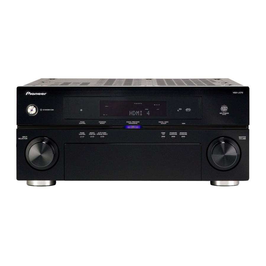
Controls and displays Chapter 4: Controls and displays Front panel Illustration shows the VSX-LX70 front panel STANDBY/ON INPUT SELECTOR SPEAKERS PHONES INPUT SELECTOR dial Use to select an input source. STANDBY/ON Switches the receiver between on and standby. Power indicator lights when the receiver is on.
-
Page 25: Operating Range Of Remote Control Unit
ST stations (page 36). 22 RETURN Press to confirm and exit the current menu screen. 23 USB interface (VSX-LX70 only) Connect a USB audio device for playback. See the separate manual for HOME MEDIA GALLERY. 24 MCACC SETUP MIC jack Use to connect the supplied microphone.
-
Page 26: Display
Controls and displays Display Illustration shows the VSX-LX70 display AUTO HDMI SBL SB DIGITAL ANALOG STREAM DIRECT PRO LOGIC ADV.SURROUND STEREO STANDARD SLEEP SIGNAL indicators Light to indicate the currently selected input signal. AUTO lights when the receiver is set to select the input signal automatically (page 32).
-
Page 27: Remote Control
GENRE – Automatically selects the most appropriate Advanced Surround mode for the genre of the source currently being played back (this feature is available only when a Pioneer DVD recorder supporting HDMI ì Control is connected to this receiver via HDMI) (page 34).
-
Page 28
Controls and displays TV CONTROL buttons These buttons are dedicated to control the TV assigned to the TV CTRL button. Thus if you only have one TV to hook up to this system assign it to the TV CTRL input source button. -
Page 29: Listening To Your System
2 For more options using this button, see Using Stream Direct on page 31. 3 VSX-LX70 only – Neural THX is selected when Neural Radio is accessed with the HOME MEDIA GALLERY input. However, Stereo is selected when a category other than Neural Radio is accessed.
-
Page 30: Using The Home Thx Modes
Listening to your system • Dolby Digital EX – Creates surround back channel sound for 5.1 channel sources and provides pure decoding for 6.1 channel sources (like Dolby Digital Surround EX) • DTS-ES – Allows you to hear 6.1 channel playback with DTS-ES encoded sources •…
-
Page 31: Listening In Stereo
Listening to your system • When an Advanced Surround listening mode is selected, the effect level can be adjusted using the EFFECT parameter in Setting the Audio options on page 68. Listening in stereo When you select STEREO, you will hear the source through just the front left and right speakers (and possibly your subwoofer depending on your speaker settings).
-
Page 32: Selecting Mcacc Presets
Listening to your system Selecting MCACC presets • Default setting: MEMORY 1 If you have calibrated your system for different listening positions , you can switch between settings to suit the kind of source you’re listening to and where you’re sitting (for example, watching movies from a sofa, or playing a video game close to the TV).
-
Page 33: Using The Virtual Surround Back Mode
Listening to your system Using the Virtual Surround Back mode When you’re not using surround back speakers, selecting this mode allows you to hear a virtual surround back channel through your surround speakers. You can choose to listen to sources with no surround back channel information, or if the material sounds better in the format (for example, 5.1) for which it was originally encoded, you can have the receiver only apply this effect…
-
Page 34: Using The Genre Synchronizing Function
This feature automatically selects the most appropriate Advanced Surround mode for the source currently being played back on a Pioneer DVD recorder supporting HDMI Control connected to this receiver via HDMI. on HDMI Control, see About HDMI on page 53.
-
Page 35: Using The Tuner
This should improve the sound quality and allow you to enjoy the broadcast. Using Neural THX VSX-LX70 only This feature uses Neural Surround™ technology to achieve optimal surround sound from FM radio. • While listening to FM radio, press S.DIRECT for Neural THX listening.
-
Page 36: Saving Station Presets
Using the tuner Saving station presets If you often listen to a particular radio station, it’s convenient to have the receiver store the frequency for easy recall whenever you want to listen to that station. This saves the effort of manually tuning in each time. This receiver can memorize up to 30 stations, stored in three banks, or classes (A, B and C) of 10 stations each.
-
Page 37: The System Setup Menu
SETUP . • You can’t use the System Setup menu when the iPod or HOME MEDIA GALLERY (VSX-LX70 only) input source is selected (in either the main or sub zone). When you set ZONE 2 or ZONE 3 to ON (page 58), you can’t use the System Setup menu.
-
Page 38
The System Setup menu Important • Make sure the microphone/speakers are not moved during the Auto MCACC Setup. • Using the Auto MCACC Setup will overwrite any existing settings for the MCACC preset you select. • The screen saver will automatically appear after three minutes of inactivity. -
Page 39
The System Setup menu Connect the microphone to the MCACC SETUP MIC jack on the front panel. Make sure there are no obstacles between the speakers and the microphone. AUDIO PARAMETER VIDEO MULTI – ZONE & SIGNAL SB ch STEREO/ (TUNE) SOURCE/REC SEL SPEAKERS… -
Page 40: Surround Back Speaker Setting
The System Setup menu You can also choose to view the settings by selecting individual parameters from the MCACC Data Check screen: • Speaker Setting – The size and number of speakers you’ve connected (see page 48 for more on this) •…
-
Page 41: Fine Channel Level
The System Setup menu • For some of the settings below, you’ll have to connect the setup microphone to the front panel and place it about ear level at your normal listening position. Press SETUP to display the System Setup menu before you connect the microphone to this receiver.
-
Page 42: Fine Speaker Distance
The System Setup menu Fine Speaker Distance • Default setting: 3.00 m (all speakers) For proper sound depth and separation with your system, it is necessary to add a slight bit of delay to some speakers so that all sounds will arrive at the listening position at the same time.
-
Page 43: Acoustic Calibration Eq Adjust
2 This system allows you to customize your system calibration with the help of a graphical output that can be displayed on-screen, or using a computer (with software available from Pioneer—see Connecting a PC for Advanced MCACC output on page 61 for more on this).
-
Page 44
The System Setup menu By analyzing the graph, you should be able to see how your room is responding to certain frequencies. Differences in channel level and speaker distance are taken into account automatically (compensation is provided for comparison purposes), and the frequency measurements can be examined both with and without the equalization performed by this receiver. -
Page 45: Full Band Phase Control
The System Setup menu If you selected ‘Reverb Measurement’, select EQ ON or OFF and then START. DVD /LD — 5 5 .0dB DVD /LD 3 e1 . R ev e rb M ea s u re m e n t 3e1.
-
Page 46: Data Management
The System Setup menu Select ‘ FULL BAND PHASE CTRL ’ from the System Setup menu. See Making receiver settings from the System Setup menu above if you’re not already at this screen. DV D /L D — 55.0dB S y s t e m Se t u p M EN U 1 .
-
Page 47: Renaming Mcacc Presets
The System Setup menu Select ‘MCACC Data Check’ from the Data Management setup menu. DV D/ L D — 55 .0dB DVD/LD 5. D a ta Ma n ag em e n t 5a. MC ACC Dat a Check 1. Speaker Set tin g a.
-
Page 48: Manual Speaker Setup
The System Setup menu Manual speaker setup This receiver allows you to make detailed settings to optimize the surround sound performance. You only need to make these settings once (unless you change the placement of your current speaker system or add new speakers).
-
Page 49: Channel Level
The System Setup menu • Subwoofer – LFE signals and bass frequencies of channels set to SMALL are output from the subwoofer when YES is selected. Choose the PLUS setting if you want the subwoofer to output bass sound continuously or you want deeper bass (the bass frequencies that would normally come out the front and center speakers are also routed to the subwoofer).
-
Page 50: X-Curve
The System Setup menu Important • When Speaker Distance is selected while MCACC is set to OFF, the selection screen for the MCACC memory appears. Select a memory to adjust manually. DVD /L D 6 c. S p e aker D ist ance S e le c t M CACC mem or y.
-
Page 51: Other Connections
2004-10-20 (plesae use the latest iPod software versions later than the iPod updater 2004-10-20). 2 • This product is the Pioneer Control Dock for iPod (IDK-90C) for use with an iPod equipped with a dock connector port (third generation and above), iPod mini, iPod nano or iPod Photo.
-
Page 52: Watching Photos And Video Content
Other connections Use the buttons to select a category then press ENTER to browse that category. • To return to the previous level, press RETURN. Use the buttons to browse the selected category (e.g., albums). • Use to move to previous/next levels. Continue browsing until you arrive at what you want to play, then press Navigation through audio categories on your iPod looks…
-
Page 53: About Hdmi
(DC OUT 12V/ TOTAL 50 mA MAX) AUDIO use with DVD players, DTV, set-top boxes, and other AV VSX-LX70 devices. HDMI was developed to provide the technologies of High Bandwidth Digital Content Protection (HDCP) as well as Digital Visual Interface (DVI) in one specification.
-
Page 54: Selecting The Multichannel Analog Inputs
Other connections Connect the front, surround, center and subwoofer outputs on your DVD player to the corresponding MULTI CH input jack on this receiver. • Use standard RCA/phono jack cables for the connections. If your DVD player also has outputs for surround back channels, connect these to the corresponding MULTI CH input jacks on this receiver.
-
Page 55: Bi-Amping Your Front Speakers
Other connections AUDIO PARAMETER VIDEO MULTI – ZONE & SOURCE/REC SEL (TUNE) SPEAKERS TUNER EDIT BAND CONTROL ON/OFF PHONES MCACC (ST) ENTER (ST) SETUP MIC (TUNE) DIGITAL IN SETUP RETURN Press repeatedly to choose a speaker system option: • SP A – Sound is output from speaker system A and the same signal is output from the pre-out terminals.
-
Page 56: Connecting Additional Amplifiers
(however, if iPod or HOME MEDIA GALLERY (VSX-LX70 only) is selected in the main zone, it cannot also be selected in the sub zone). The main and…
-
Page 57
Other connections MULTI-ZONE listening options The following table shows what you can listen to in each sub zone: Sub Zone Input sources available ZONE2 iPod, the built-in tuner and other analog audio sources. With video sources, only composite video is possible. ZONE3 Only digital audio sources (the input source must already be assigned using the The Input… -
Page 58: Using The Multi-Zone Controls
(see Saving station presets on page 36 if you’re unsure how to do this). (VSX-LX70 only) functions simultaneously using the MULTI-ZONE feature. Use the MASTER VOLUME dial to adjust the When you’re finished, press CONTROL again to…
-
Page 59: Switching Components On And Off Using The 12 Volt Trigger
Note 1 The 3-ringed SR+ cable from Pioneer is commercially available under the part number ADE7095. Contact the Pioneer Customer Support division for more information on obtaining an SR+ cable (you can also use a commercially available 3-ringed mini phone plug for the connection).
-
Page 60: Using The Sr+ Mode With A Pioneer Plasma Display
ON. Make sure to set HDMI Control to OFF when you use the SR+ features (page 63). • If you connect to a Pioneer plasma display using an SR+ cable, you will need to point the remote control at the plasma display remote sensor to control the receiver.
-
Page 61: Connecting A Pc For Advanced Mcacc Output
(the cable must be cross type, female-female). The software to output the results is available by contacting the Pioneer Authorized Distributor for your area (as listed on page 95 of this manual) as well as the instructions necessary for using it.
-
Page 62: Hdmi Control
Chapter 9 HDMI Control By connecting this receiver to an HDMI Control- compatible Pioneer plasma display or the HDD/DVD recorder with an HDMI cable, you can control this receiver from the remote control of a connected plasma display, as well as have the connected plasma display automatically change inputs in response to operations carried out on this unit.
-
Page 63: Setting The Hdmi Options
Choose whether to set this unit’s HDMI Control function ON or OFF. You will need to set it to ON to use the HDMI Control function. • When using a TV not manufactured by Pioneer, put this setting to OFF. Press RECEIVER on the remote control, then press the SETUP button.
-
Page 64: Other Settings
2 You will have to make an SR+ cable connection from a CONTROL OUT jack on the display to the CONTROL IN jack on this receiver (opposite from the setup in Using this receiver with a Pioneer plasma display on page 59). Note that to control this receiver using the remote, you will have to point it at the plasma display’s remote sensor after making this connection.
-
Page 65: Input Function Default And Possible Settings
• ZONE Audio Setup – Specify your volume setting for a MULTI-ZONE setup (see ZONE Audio Setup below). • SR+ Setup – Specify how you want to control your Pioneer plasma display (see SR+ Setup for Pioneer plasma displays below). • HDMI Control Setup – Synchronizes this receiver…
-
Page 66: Multi Channel Input Setup
See also Using this receiver with a Pioneer plasma display on page 59 and Using the SR+ mode with a Pioneer plasma display on page 60. Select ‘SR+ Setup’ from the Other Setup menu.
-
Page 67: Osd Adjustment
Other Settings Select the ‘ PDP Volume Control ’ setting you want. • OFF – The receiver does not control the volume of the plasma display. • ON – When the receiver is switched to one of the inputs that use the plasma display (DVD/LD, for example), the volume on the plasma display is muted so only sound from the receiver is heard.
-
Page 68: Using Other Functions
Using other functions Chapter 11: Using other functions Setting the Audio options There are a number of additional sound settings you can make using the Audio Parameter menu. The defaults, if not stated, are listed in bold. Important • Note that if a setting doesn’t appear in the Audio Parameter menu, it is unavailable due to the current source, settings and status of the receiver.
-
Page 69: Setting The Video Options
Using other functions Setting What it does LFE ATT Some Dolby Digital and DTS audio (LFE sources include ultra-low bass Attenuate) tones. Set the LFE attenuator as necessary to prevent the ultra-low bass tones from distorting the sound from the speakers. The LFE is not limited when set to 0 dB, which is the recommended value.
-
Page 70: Making An Audio Or A Video Recording
Using other functions Setting What it does Specifies the output resolution of the video signal (when analog video (Resolution) input signals are output at the HDMI OUT connector, select this according to the resolution of your monitor and the images you wish to watch).
-
Page 71: Reducing The Level Of An Analog Signal
Using other functions During recording, press the REC SELECT CONTROL button on the front panel until RECOUT shows in the display. While RECOUT shows in the display, use the INPUT SELECTOR dial to select the source you want to record. The default, RECOUT SOURCE, records the source you’re currently listening to (as in Making an audio or a video recording above).
-
Page 72: Checking Your System Settings
Using other functions Checking your system settings Use the status display screen to check your current settings for features such as surround back channel processing and your current MCACC preset. AUDIO SUBTITLE DISP PHOTO T.DISP STATUS STATUS SIGNAL SEL MULTI OPE SHIFT PHASE Press STATUS to check the system settings.
-
Page 73
Using other functions Setting Effect Level ExtendedStereo Other modes 2 PL II Music Options Center Width Dimension Panorama Neo:6 Options Center Image All Inputs Listening Mode (2 ch) AUTO SURROUND Listening Mode (x ch) AUTO SURROUND Listening Mode (HP) See also Setting the Audio options on page 68 for other default DSP settings. -
Page 74: Controlling The Rest Of Your System
2 • When using a Pioneer HDD recorder, please select PIONEER DVR 487, 488, 489 or 493. • When using a Pioneer plasma display released prior to summer 2005, please select preset codes 637 or 660. 3 The remote can store about 200 preset codes (this has been tested with codes of Pioneer format only).
-
Page 75: Erasing One Of The Remote Control Button Settings
Controlling the rest of your system Point the two remote controls towards each other then press the button that will be doing the learning on this receiver’s remote control. PRES KEY starts flashing to indicate the remote is ready to accept a signal. •…
-
Page 76: Renaming Input Source Names
Controlling the rest of your system Press the button of the component for which you want to check the preset code, then press ENTER . The brand name and preset code appears in the display for three seconds. Renaming input source names You can customize the names that appear on the remote LCD when you select an input source (for example, you could change the name of DVR 1 to HDD/DVR).
-
Page 77: Using Multi Operations
(except DVD recorders); • program the power to switch on if it’s the source component selected in step 3; • program a Pioneer TV or monitor to switch on if the input function (selected in step 2) has video input terminals;…
-
Page 78: Controls For Other Components
Controlling the rest of your system • The TV CONTROL buttons on the remote control are dedicated to control the TV assigned to the TV CTRL button. If you have two TVs, assign the main TV to the TV CTRL button. Button(s) Function Press to switch the component assigned to the TV CTRL…
-
Page 79: Operating Other Pioneer Components With This Unit’s Sensor
If you have connected a remote control to the CONTROL IN jack (using a mini-plug cable), you won’t be able to control this unit using the remote sensor. • See Using this receiver with a Pioneer plasma display on page 59 if you are connecting a Pioneer plasma display.
-
Page 80: Additional Information
• Something is obstructing the fan. Remove the obstruction and try switching the receiver back on. If the fan is still not working, or you can’t remove the object, unplug the receiver from the wall and call a Pioneer authorized independent service company.
-
Page 81: Other Audio Problems
Additional information Symptom Remedy No sound from the surround or • Check that the Stereo listening mode or the Front Stage Surround Advance mode isn’t selected; select center speakers. one of the surround listening modes (see Listening in surround sound on page 29). •…
-
Page 82: Video
Additional information Symptom Noise is output when scanning a DTS CD. When playing a DTS format LD there is audible noise on the soundtrack. Can’t record audio. Recorded audio is different from the current source, or inaudible. Subwoofer output is very low. Everything seems to be set up correctly, but the playback sound is odd.
-
Page 83: Settings
Additional information Symptom Remedy Can’t record video. • Check that the source is not copy-protected. • The video converter is not available when making recordings. Check that the same type of video cable is used for connecting both the recorder and the video source (the one you want to record) to this receiver. Noisy, intermittent, or distorted •…
-
Page 84: Remote Control
• If the battery ran down, the preset codes may have been cleared. Re-enter the preset codes. • The preset code may be incorrect. Redo the procedure for entering preset codes. • Reinsert the SR cable, making sure it’s connected to the right jack (see Using this receiver with a Pioneer plasma display on page 59).
-
Page 85: Ipod Messages
Additional information Symptom Remedy No picture or sound. • This receiver is HDCP-compatible. Check that the components you are connecting are also HDCP- compatible. If they are not, please connect them using the component, S-video or composite video jacks. • Depending on the connected source component, it’s possible that it will not work with this receiver (even if it is HDCP-compatible).
-
Page 86: Surround Sound Formats
Additional information Surround sound formats Below is a brief description of the main surround sound formats you’ll find on DVDs, satellite, cable and terrestrial broadcasts, and video cassettes. Dolby The Dolby technologies are explained below. See www.dolby.com for more detailed information. Dolby Digital Dolby Digital is a multichannel digital audio coding system widely used in cinemas, and in the home for DVD and digital…
-
Page 87: Dts
Additional information The DTS technologies are explained below. See www.dtstech.com for more detailed information. DTS Digital Surround DTS Digital Surround is a 5.1-channel audio coding system from DTS Inc. now widely used for DVD-Video, DVD-Audio, 5.1 music discs, digital broadcasts, and video games. It can deliver up to six discrete audio channels, comprising five full range channels, including an LFE channel.
-
Page 88: About Neural Surround
THX and the THX logo are trademarks of THX Ltd. which may be registered in some jurisdictions. All rights reserved. About Neural Surround VSX-LX70 only Neural Surround represents the latest advancement in surround technology and has been adopted by FM Radio and Neural Music Direct for broadcasts of surround recordings and live events.
-
Page 89: Listening Modes With Different Input Signal Formats
Additional information Listening modes with different input signal formats The following charts outline the listening modes available with different input signal formats, depending on the surround back channel processing and decoding method you have selected. Stereo (2 channel) signal formats SBch Processing Input signal format SBch…
-
Page 90
Pro Logic has a maximum of 5.1 channel playback. b.Unavailable with only one surround back speaker connected. c.VSX-LX70 only – Available only with the FM or HOME MEDIA GALLERY input. d.Automatically selected if no surround back speakers are connected. -
Page 91
Additional information SBch Processing Input signal format SBch DTS-ES Processing (6.1 channel sources/ 6.1 channel flagged) (7.1 channel decoding used for all sources) DTS and DTS 96/24 (5.1 channel encoding) Dolby Digital WMA9 Pro (44.1 kHz/48 kHz) (5.1 channel encoding) SACD (5.1 channel encoding) SBch… -
Page 92: Stream Direct With Different Input Signal Formats
Stereo (2 channel) signal formats Surround Back speaker(s) Connected (Maximum 7.1 channel playback) Not connected (Maximum 5.1 channel playback) a.SACD DIRECT (VSX-LX70) or Straight decoding (VSX-LX60) Multichannel signal formats Surround Back speaker(s) Connected (Maximum 7.1 channel playback) Not connected (Maximum 5.1 channel playback) a.Unavailable with only one surround back speaker connected.
-
Page 93: Specifications
……..1 Flat-bladed converter plug These operating instructions Operating instructions for HOME MEDIA GALLERY (VSX-LX70 only) Note • Specifications and the design are subject to possible modifications without notice, due to improvements.
-
Page 94: Cleaning The Unit
Our philosophy Pioneer is dedicated to making your home theater listening experience as close as possible to the vision of the moviemakers and mastering engineer when they created the original soundtrack.
-
Page 95: Pioneer Authorized Distributors
When using the Advanced MCACC setup, you have the option of displaying the results using a computer. To obtain the software for this feature (as referred to in Connecting a PC for Advanced MCACC output on page 61), please contact the Pioneer Authorized Distributor for your area as listed above. •…
-
Page 96
253 Alexandra Road, #04-01, Singapore 159936 TEL: 65-6472-7555 PIONEER ELECTRONICS AUSTRALIA PTY. LTD. 178-184 Boundary Road, Braeside, Victoria 3195, Australia, TEL: (03) 9586-6300 PIONEER ELECTRONICS DE MEXICO S.A. DE C.V. Blvd.Manuel Avila Camacho 138 10 piso Col.Lomas de Chapultepec, Mexico,D.F. 11000 TEL: 55-9178-4270 K002_B_En Published by Pioneer Corporation.
This manual is also suitable for:
Vsx-lx60
VSX_LX60LX70_Ru.book Page 1 Tuesday, June 5, 2007 8:36 PM
VSX_LX60LX70_Ru.book Page 2 Tuesday, June 5, 2007 8:36 PM
CAUTION
RISK OF ELECTRIC SHOCK
DO NOT OPEN
D3-4-2-1-1_Ru-A
VSX_LX60LX70_Ru.book Page 3 Tuesday, June 5, 2007 8:36 PM

VSX_LX60LX70_Ru.book Page 4 Tuesday, June 5, 2007 8:36 PM
Содержание
01 Перед началом работы
05 Прослушивание системы
Проверка комплекта поставки. . . . . . . . . . . . . . . . . . . . . 6
Автоматическое воспроизведение . . . . . . . . . . . . . . . . 28
Установка ресивера . . . . . . . . . . . . . . . . . . . . . . . . . . . . . 6
Прослушивание материала с использованием
Установка батареек. . . . . . . . . . . . . . . . . . . . . . . . . . . . . . 6
объемного звучания . . . . . . . . . . . . . . . . . . . . . . . . . . . . 28
Стандартное объемное звучание . . . . . . . . . . . . . . . . 28
Использование режимов Home THX . . . . . . . . . . . . . 29
02 Краткое руководство
Использование дополнительных эффектов
Ознакомление с системой домашнего кинотеатра . . . . 7
объемного звучания. . . . . . . . . . . . . . . . . . . . . . . . . . . 29
Прослушивание в режиме объемного звучания . . . . . . 7
Прослушивание в стереофоническом режиме . . . . . . 30
Автоматическая настройка для объемного звучания
Использование Front Stage Surround Advance . . . . . . . 30
(MCACC & Full Band Phase Control). . . . . . . . . . . . . . . . 8
Использование функции Stream Direct . . . . . . . . . . . . 30
Проблемы при использовании автоматической
Выбор предварительно заданных настроек MCACC
. . . . 31
настройки MCACC. . . . . . . . . . . . . . . . . . . . . . . . . . . . . 9
Выбор входного сигнала . . . . . . . . . . . . . . . . . . . . . . . . 31
Воспроизведение источника . . . . . . . . . . . . . . . . . . . . . . 9
Использование обработки заднего канала объемного
Улучшение звучания с помощью Phase Control и Full
звучания . . . . . . . . . . . . . . . . . . . . . . . . . . . . . . . . . . . . . 31
Band Phase Control . . . . . . . . . . . . . . . . . . . . . . . . . . . . . 10
Использование режима виртуального заднего
Использование Phase Control . . . . . . . . . . . . . . . . . . . 10
громкоговорителя объемного звучания . . . . . . . . . . 32
Использование Full Band Phase Control . . . . . . . . . . . 11
Использование функции синхронизации жанра . . . . . 33
03 Подключение оборудования
06 Воспроизведение устройств с
Задняя панель . . . . . . . . . . . . . . . . . . . . . . . . . . . . . . . . . 12
Подключение кабелей . . . . . . . . . . . . . . . . . . . . . . . . . . 13
интерфейсом USB
О преобразователе видеосигнала . . . . . . . . . . . . . . . . . 13
Использование интерфейса USB . . . . . . . . . . . . . . . . . 34
Подключение телевизора и проигрывателя дисков DVD
. . . 14
Основные органы управления воспроизведением . . . 34
Подключение проигрывателя Blu-ray дисков . . . . . . . 14
Выбор файла из списка папок/файлов для
Подключение спутникового/кабельного ресивера или
воспроизведения. . . . . . . . . . . . . . . . . . . . . . . . . . . . . . . 34
другой приставки . . . . . . . . . . . . . . . . . . . . . . . . . . . . . . 15
Поддержка сжатых аудиосигналов . . . . . . . . . . . . . . 35
Подключение рекордера DVD/HDD,
видеомагнитофона и других аудиоисточников . . . . . . 16
07 Использование тюнера
Использование разъемов компонентного видео . . . . . 16
Прослушивание радиопередач . . . . . . . . . . . . . . . . . . . 36
Подключение цифровых аудиоисточников . . . . . . . . . 17
Повышение качества стереозвука в диапазоне FM
. . . 36
О декодере WMA9 Pro. . . . . . . . . . . . . . . . . . . . . . . . . 17
Использование Neural THX . . . . . . . . . . . . . . . . . . . . 36
Подключение аналоговых аудиоисточников . . . . . . . . 18
Непосредственное указание частоты. . . . . . . . . . . . . 36
Подключение компонента к входам на передней панели
. . . 18
Сохранение запрограммированных радиостанций
. . . . 36
Установка акустической системы . . . . . . . . . . . . . . . . . 19
Присвоение имен запрограммированным радиостанциям
. . . 37
Подключение громкоговорителей . . . . . . . . . . . . . . . 19
Прослушивание запрограммированных радиостанций
. . . 37
Расположение громкоговорителей . . . . . . . . . . . . . . . 20
Знакомство с системой RDS . . . . . . . . . . . . . . . . . . . . . 37
Настройка системы громкоговорителей THX. . . . . . 21
Поиск программ RDS . . . . . . . . . . . . . . . . . . . . . . . . . 38
Подключение антенн . . . . . . . . . . . . . . . . . . . . . . . . . . . 21
Использование функции EON. . . . . . . . . . . . . . . . . . . . 38
Рамочная антенна АМ . . . . . . . . . . . . . . . . . . . . . . . . . 21
Проволочная антенна FM . . . . . . . . . . . . . . . . . . . . . . 22
08 Меню System Setup
Подключение внешних антенн . . . . . . . . . . . . . . . . . . 22
Настройка параметров ресивера в меню System Setup
. . . 39
Подключение ресивера к электророзетке. . . . . . . . . . . 22
Автоматическая настройка MCACC (Expert) . . . . . . . 39
Выход переменного тока . . . . . . . . . . . . . . . . . . . . . . . . 22
Настройка задних громкоговорителей объемного звучания
. . . 42
Ручная настройка MCACC . . . . . . . . . . . . . . . . . . . . . . 42
04 Органы управления и индикаторы
Fine Channel Level . . . . . . . . . . . . . . . . . . . . . . . . . . . . 43
Передняя панель . . . . . . . . . . . . . . . . . . . . . . . . . . . . . . . 23
Fine Speaker Distance . . . . . . . . . . . . . . . . . . . . . . . . . . 44
Дальность действия пульта ДУ. . . . . . . . . . . . . . . . . . 24
Standing Wave. . . . . . . . . . . . . . . . . . . . . . . . . . . . . . . . 44
Дисплей . . . . . . . . . . . . . . . . . . . . . . . . . . . . . . . . . . . . . . 25
Настройка эквалайзера акустической калибровки
. . . . 45
Пульт ДУ . . . . . . . . . . . . . . . . . . . . . . . . . . . . . . . . . . . . . 26
Эквалайзер профессиональной акустической
калибровки . . . . . . . . . . . . . . . . . . . . . . . . . . . . . . . . . . 45
Full Band Phase Control . . . . . . . . . . . . . . . . . . . . . . . . . 47
Data Management . . . . . . . . . . . . . . . . . . . . . . . . . . . . . . 48
4
Ru

VSX_LX60LX70_Ru.book Page 5 Tuesday, June 5, 2007 8:36 PM
Ручная настройка громкоговорителей . . . . . . . . . . . . . 50
Использование таймера отключения . . . . . . . . . . . . . . 73
Speaker Setting. . . . . . . . . . . . . . . . . . . . . . . . . . . . . . . . 50
Затемнение дисплея . . . . . . . . . . . . . . . . . . . . . . . . . . . . 73
Channel Level . . . . . . . . . . . . . . . . . . . . . . . . . . . . . . . . 51
Изменение сопротивления громкоговорителей . . . . . 73
Speaker Distance . . . . . . . . . . . . . . . . . . . . . . . . . . . . . . 51
Проверка настроек системы . . . . . . . . . . . . . . . . . . . . . 74
X-Curve . . . . . . . . . . . . . . . . . . . . . . . . . . . . . . . . . . . . . 52
Сброс настроек системы . . . . . . . . . . . . . . . . . . . . . . . . 74
THX Audio Setting . . . . . . . . . . . . . . . . . . . . . . . . . . . . 52
Настройки системы по умолчанию . . . . . . . . . . . . . . 74
09 Другие подключения
13 Управление остальными частями системы
Подключение проигрывателя iPod . . . . . . . . . . . . . . . . 53
Настройка пульта ДУ для работы с другими
Подключение проигрывателя iPod к ресиверу . . . . . 53
компонентами . . . . . . . . . . . . . . . . . . . . . . . . . . . . . . . . . 76
Воспроизведение на проигрывателе iPod . . . . . . . . . 53
Непосредственный ввод кодов компонентов . . . . . . . 76
Просмотр фотографий и видеоматериалов . . . . . . . . 54
Программирование сигналов от других пультов ДУ
. . . 76
Подключение с помощью HDMI. . . . . . . . . . . . . . . . . . 54
Стирание одной из настроек кнопки пульта ДУ. . . . . 77
О HDMI . . . . . . . . . . . . . . . . . . . . . . . . . . . . . . . . . . . . . . 55
Сброс предварительно заданных настроек пульта ДУ
. . . 77
Подключение многоканальных аналоговых входов
. . . 55
Подтверждение предварительно заданных кодов. . . . 78
Выбор многоканальных аналоговых входов . . . . . . . 56
Переименование источника входа . . . . . . . . . . . . . . . . 78
Настройка громкоговорителей зоны В . . . . . . . . . . . . . 56
Функция Direct . . . . . . . . . . . . . . . . . . . . . . . . . . . . . . . . 78
Смена настройки акустической системы. . . . . . . . . . 56
Групповые операции (Multi Operation) и
Подключение передних громкоговорителей к двум
выключение системы (System Off) . . . . . . . . . . . . . . . . 78
усилителям. . . . . . . . . . . . . . . . . . . . . . . . . . . . . . . . . . . . 57
Программирование групповой операции или
Двухпроводное подключение громкоговорителей . . . 57
последовательности выключения . . . . . . . . . . . . . . . 78
Подключение дополнительных усилителей. . . . . . . . . 58
Использование групповых операций. . . . . . . . . . . . . 79
Прослушивание MULTI-ZONE . . . . . . . . . . . . . . . . . . . 58
Использование выключения системы . . . . . . . . . . . . 79
Выполнение соединений MULTI-ZONE . . . . . . . . . . 58
Органы управления телевизорами . . . . . . . . . . . . . . . . 79
Использование органов управления MULTI-ZONE
. . . 60
Органы управления другими компонентами. . . . . . . . 80
Подключение ИК приемника. . . . . . . . . . . . . . . . . . . . . 60
Управление другими компонентами Pioneer с
Включение и отключение компонентов с помощью
помощью пульта данного устройства . . . . . . . . . . . . . 81
12-вольтного пускового устройства . . . . . . . . . . . . . . . 61
Использование ресивера с плазменным дисплеем Pioneer
. . . . 61
14 Дополнительная информация
Использование режима SR+ с плазменными
Устранение неполадок. . . . . . . . . . . . . . . . . . . . . . . . . . 82
дисплеями Pioneer . . . . . . . . . . . . . . . . . . . . . . . . . . . . . . 62
Питание . . . . . . . . . . . . . . . . . . . . . . . . . . . . . . . . . . . . 82
Подключение компьютера для вывода Advanced MCACC
. . . . 63
Отсутствие звука . . . . . . . . . . . . . . . . . . . . . . . . . . . . . 83
Вывод Advanced MCACC с помощью компьютера
. . . . 63
Другие проблемы со звуком. . . . . . . . . . . . . . . . . . . . 84
Видео . . . . . . . . . . . . . . . . . . . . . . . . . . . . . . . . . . . . . . 85
10 HDMI Control
Настройки. . . . . . . . . . . . . . . . . . . . . . . . . . . . . . . . . . . 85
Выполнение соединений HDMI Control (Управление HDMI)
. . . 64
Графический вывод эквалайзера
Настройка опций HDMI . . . . . . . . . . . . . . . . . . . . . . . . . 65
профессиональной калибровки . . . . . . . . . . . . . . . . . 86
Настройка режима HDMI Control. . . . . . . . . . . . . . . . 65
Дисплей . . . . . . . . . . . . . . . . . . . . . . . . . . . . . . . . . . . . 86
Перед использованием синхронизации . . . . . . . . . . . . 65
Пульт ДУ . . . . . . . . . . . . . . . . . . . . . . . . . . . . . . . . . . . 87
Режим синхронизированного усиления . . . . . . . . . . . . 65
HDMI . . . . . . . . . . . . . . . . . . . . . . . . . . . . . . . . . . . . . . 87
Операции режима синхронизированного усиления
. . . 65
Интерфейс USB (только VSX-LX60). . . . . . . . . . . . . 88
Отмена режима синхронизированного усиления . . . 65
Сообщения устройств iPod . . . . . . . . . . . . . . . . . . . . . 88
Об HDMI Control. . . . . . . . . . . . . . . . . . . . . . . . . . . . . . . 65
Форматы объемного звучания . . . . . . . . . . . . . . . . . . . 89
Dolby . . . . . . . . . . . . . . . . . . . . . . . . . . . . . . . . . . . . . . . 89
DTS . . . . . . . . . . . . . . . . . . . . . . . . . . . . . . . . . . . . . . . . 90
11 Другие параметры
Windows Media Audio 9 Professional . . . . . . . . . . . . . 90
Меню Input Setup . . . . . . . . . . . . . . . . . . . . . . . . . . . . . . 66
О THX . . . . . . . . . . . . . . . . . . . . . . . . . . . . . . . . . . . . . . . 90
Стандартные и возможные настройки функций входа
. . . 67
О Neural Surround . . . . . . . . . . . . . . . . . . . . . . . . . . . . . . 91
Меню Other Setup . . . . . . . . . . . . . . . . . . . . . . . . . . . . . . 67
Режимы прослушивания для других форматов
Multi Channel Input Setup . . . . . . . . . . . . . . . . . . . . . . . 68
входных сигналов. . . . . . . . . . . . . . . . . . . . . . . . . . . . . . 92
ZONE Audio Setup . . . . . . . . . . . . . . . . . . . . . . . . . . . . 68
Stream direct для других форматов входных сигналов
. . . 95
Параметры настройки SR+ для плазменных
Технические характеристики . . . . . . . . . . . . . . . . . . . . 96
дисплеев Pioneer . . . . . . . . . . . . . . . . . . . . . . . . . . . . . . 68
Чистка устройства . . . . . . . . . . . . . . . . . . . . . . . . . . . . . 97
OSD Adjustment . . . . . . . . . . . . . . . . . . . . . . . . . . . . . . 69
Наша философия . . . . . . . . . . . . . . . . . . . . . . . . . . . . . . 97
Особенности. . . . . . . . . . . . . . . . . . . . . . . . . . . . . . . . . 97
12 Использование других функций
Настройка аудиоопций. . . . . . . . . . . . . . . . . . . . . . . . . . 70
Настройка видеоопций . . . . . . . . . . . . . . . . . . . . . . . . . . 71
Выполнение аудио— или видеозаписи . . . . . . . . . . . . . . 72
Воспроизведение другого источника во время записи
. . . 72
Уменьшение уровня аналогового сигнала . . . . . . . . . . 73
5
Ru
![]()
Operating Instructions
AUDIO/VIDEO MULTI-CHANNEL RECEIVER
K041_En
D3-4-2-1-7b_A_En
D3-4-2-1-7c_A_En
D3-4-2-1-3_A_En
D3-4-2-1-7a_A_En
D3-4-2-2-1a_A_En
D3-4-2-1-4_A_En
IMPORTANT
CAUTION
RISK OF ELECTRIC SHOCK
DO NOT OPEN
The lightning flash with arrowhead symbol, within an equilateral triangle, is intended to alert the user to the presence of uninsulated «dangerous voltage» within the product’s enclosure that may be of sufficient magnitude to constitute a risk of electric shock to persons.
CAUTION:
TO PREVENT THE RISK OF ELECTRIC SHOCK, DO NOT REMOVE COVER (OR BACK). NO USER-SERVICEABLE PARTS INSIDE. REFER SERVICING TO QUALIFIED SERVICE PERSONNEL.
The exclamation point within an equilateral triangle is intended to alert the user to the presence of important operating and maintenance (servicing) instructions in the literature accompanying the appliance.
D3-4-2-1-1_En-A
WARNING
Before plugging in for the first time, read the following section carefully.
The voltage of the available power supply differs according to country or region. Be sure that the power supply voltage of the area where this unit will be used meets the required voltage (e.g., 230 V or 120 V) written on the rear panel.
WARNING
To prevent a fire hazard, do not place any naked flame sources (such as a lighted candle) on the equipment.
WARNING
This equipment is not waterproof. To prevent a fire or shock hazard, do not place any container filled with liquid near this equipment (such as a vase or flower pot) or expose it to dripping, splashing, rain or moisture.
VENTILATION CAUTION
When installing this unit, make sure to leave space around the unit for ventilation to improve heat radiation (at least 60 cm at top, 10 cm at rear, and 30 cm at each side).
WARNING
Slots and openings in the cabinet are provided for ventilation to ensure reliable operation of the product, and to protect it from overheating. To prevent fire hazard, the openings should never be blocked or covered with items (such as newspapers, table-cloths, curtains) or by operating the equipment on thick carpet or a bed.
This product is for general household purposes. Any failure due to use for other than household purposes (such as long-term use for business purposes in a restaurant or use in a car or ship) and which requires repair will be charged for even during the warranty period.
If the AC plug of this unit does not match the AC outlet you want to use, the plug must be removed and appropriate one fitted. Replacement and mounting of an AC plug on the power supply cord of this unit should be performed only by qualified service personnel. If connected to an AC outlet, the cut-off plug can cause severe electrical shock. Make sure it is properly disposed of after removal.
The equipment should be disconnected by removing the mains plug from the wall socket when left unused for a long period of time (for example, when on vacation).
CAUTION
The STANDBY/ON switch on this unit will not completely shut off all power from the AC outlet. Since the power cord serves as the main disconnect device for the unit, you will need to unplug it from the AC outlet to shut down all power. Therefore, make sure the unit has been installed so that the power cord can be easily unplugged from the AC outlet in case of an accident. To avoid fire hazard, the power cord should also be unplugged from the AC outlet when left unused for a long period of time (for example, when on vacation).
D3-4-2-2-2a_A_En
Operating Environment
Operating environment temperature and humidity: +5 ºC to +35 ºC (+41 ºF to +95 ºF); less than 85 %RH (cooling vents not blocked)
Do not install this unit in a poorly ventilated area, or in locations exposed to high humidity or direct sunlight (or strong artificial light)
For Australia Model
C67-7-3_En
Voltage selector
You can find the voltage selector switch on the rear panel of multi-voltage models.
The factory setting for the voltage selector is 220 V. Please set it to the correct voltage for your country or region.
Before changing the voltage, disconnect the AC power cord. Use a medium size screwdriver to change the voltage selector switch.
Medium size screwdriver
D3-4-2-1-5_En
Changing the TV format setting
If the System Setup menu is not displayed correctly, it may be that the TV system is set incorrectly for your country or region.
1With the receiver in standby, press STANDBY/
ON while holding down the SETUP button.
2Select PAL/NTSC using / , then select PAL or NTSC using / .
The display shows the new setting (PAL or NTSC).
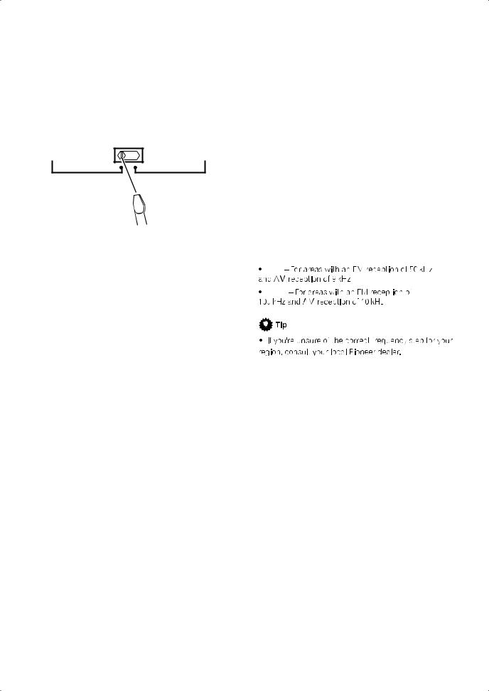
Changing the frequency step
If you find that you cannot tune into stations successfully, the frequency step may not be suitable for your country/region. Heres how to switch the setting:
1With the receiver in standby, press STANDBY/
ON while holding down the SETUP button.
2Select FREQ.STEP using / , then select 9k or 10k using / .
The display shows the new setting:
9k
10k

Thank you for buying this Pioneer product. Please read through these operating instructions so you will know how to operate your model properly. After you have finished reading the instructions, put them away in a safe place for future reference.
Contents
01 Before you start
Checking what’s in the box. . . . . . . . . . . . . . . . . . . . . . . 6 Installing the receiver . . . . . . . . . . . . . . . . . . . . . . . . . . . 6 Loading the batteries. . . . . . . . . . . . . . . . . . . . . . . . . . . . 6
02 5 minute guide
Introduction to home theater . . . . . . . . . . . . . . . . . . . . . 7 Listening to Surround Sound . . . . . . . . . . . . . . . . . . . . . 7 Automatically setting up for surround sound
(MCACC & Full Band Phase Control) . . . . . . . . . . . . . . . 8 Problems when using the Auto MCACC Setup . . . . . 9 Playing a source. . . . . . . . . . . . . . . . . . . . . . . . . . . . . . . . 9
Better sound using Phase Control and Full Band Phase Control. . . . . . . . . . . . . . . . . . . . . . . . . . . . . . . . . 10
Using Phase Control . . . . . . . . . . . . . . . . . . . . . . . . . . 10 Using Full Band Phase Control . . . . . . . . . . . . . . . . . 11
03 Connecting your equipment
Rear panel . . . . . . . . . . . . . . . . . . . . . . . . . . . . . . . . . . . 12 When making cable connections. . . . . . . . . . . . . . . . . 13 About the video converter . . . . . . . . . . . . . . . . . . . . . . . 13 Connecting your TV and DVD player . . . . . . . . . . . . . . 14 Connecting your Blu-ray disc player . . . . . . . . . . . . . . 14 Connecting a satellite/cable receiver or other
set-top box . . . . . . . . . . . . . . . . . . . . . . . . . . . . . . . . . . . 15 Connecting a DVD/HDD recorder, VCR and other video sources . . . . . . . . . . . . . . . . . . . . . . . . . . . . . . . . . 16 Using the component video jacks . . . . . . . . . . . . . . . . 16 Connecting digital audio sources . . . . . . . . . . . . . . . . 17
About the WMA9 Pro decoder . . . . . . . . . . . . . . . . . . 17 Connecting analog audio sources . . . . . . . . . . . . . . . . 18 Connecting a component to the front panel inputs . . 18 Installing your speaker system . . . . . . . . . . . . . . . . . . . 19 Connecting the speakers . . . . . . . . . . . . . . . . . . . . . . 19 Placing the speakers. . . . . . . . . . . . . . . . . . . . . . . . . . 20 THX speaker system setup . . . . . . . . . . . . . . . . . . . . . 21 Connecting antennas . . . . . . . . . . . . . . . . . . . . . . . . . . 21 AM loop antenna. . . . . . . . . . . . . . . . . . . . . . . . . . . . . 21 FM wire antenna . . . . . . . . . . . . . . . . . . . . . . . . . . . . . 22
Connecting external antenna to improve FM reception . . . . . . . . . . . . . . . . . . . . . . . . . . . . . . . . . . . 22 Using an external antenna to improve AM
reception . . . . . . . . . . . . . . . . . . . . . . . . . . . . . . . . . . . 23 Plugging in the receiver . . . . . . . . . . . . . . . . . . . . . . . . 23
05 Listening to your system
Auto playback . . . . . . . . . . . . . . . . . . . . . . . . . . . . . . . . 29 Listening in surround sound . . . . . . . . . . . . . . . . . . . . 29 Standard surround sound . . . . . . . . . . . . . . . . . . . . . 29 Using the Home THX modes . . . . . . . . . . . . . . . . . . . 30 Using the Advanced surround effects . . . . . . . . . . . 30 Listening in stereo. . . . . . . . . . . . . . . . . . . . . . . . . . . . . 31 Using Front Stage Surround Advance . . . . . . . . . . . . 31 Using Stream Direct . . . . . . . . . . . . . . . . . . . . . . . . . . . 31 Selecting MCACC presets . . . . . . . . . . . . . . . . . . . . . . 32 Choosing the input signal . . . . . . . . . . . . . . . . . . . . . . 32 Using surround back channel processing . . . . . . . . . 32 Using the Virtual Surround Back mode . . . . . . . . . . 33 Using the genre synchronizing function. . . . . . . . . . . 34
06 Using the tuner
Listening to the radio . . . . . . . . . . . . . . . . . . . . . . . . . . 35 Improving FM stereo sound. . . . . . . . . . . . . . . . . . . . 35 Using Neural THX. . . . . . . . . . . . . . . . . . . . . . . . . . . . 35 Tuning directly to a station . . . . . . . . . . . . . . . . . . . . 35 Saving station presets . . . . . . . . . . . . . . . . . . . . . . . . . 36 Naming station presets . . . . . . . . . . . . . . . . . . . . . . . 36 Listening to station presets . . . . . . . . . . . . . . . . . . . . 36
07 The System Setup menu
Making receiver settings from the System Setup
menu . . . . . . . . . . . . . . . . . . . . . . . . . . . . . . . . . . . . . . . 37 Automatic MCACC (Expert) . . . . . . . . . . . . . . . . . . . . . 37 Surround back speaker setting . . . . . . . . . . . . . . . . . . 40 Manual MCACC setup . . . . . . . . . . . . . . . . . . . . . . . . . 40 Fine Channel Level . . . . . . . . . . . . . . . . . . . . . . . . . . . 41 Fine Speaker Distance . . . . . . . . . . . . . . . . . . . . . . . . 42 Standing Wave . . . . . . . . . . . . . . . . . . . . . . . . . . . . . . 42 Acoustic Calibration EQ Adjust . . . . . . . . . . . . . . . . 43 Acoustic Calibration EQ Professional . . . . . . . . . . . 43 Full Band Phase Control . . . . . . . . . . . . . . . . . . . . . . . 45 Data Management . . . . . . . . . . . . . . . . . . . . . . . . . . . . 46 Manual speaker setup . . . . . . . . . . . . . . . . . . . . . . . . . 48 Speaker Setting . . . . . . . . . . . . . . . . . . . . . . . . . . . . . 48 Channel Level . . . . . . . . . . . . . . . . . . . . . . . . . . . . . . . 49 Speaker Distance . . . . . . . . . . . . . . . . . . . . . . . . . . . . 49 X-Curve . . . . . . . . . . . . . . . . . . . . . . . . . . . . . . . . . . . . 50 THX Audio Setting . . . . . . . . . . . . . . . . . . . . . . . . . . . 50
04 Controls and displays
Front panel . . . . . . . . . . . . . . . . . . . . . . . . . . . . . . . . . . . 24 Operating range of remote control unit . . . . . . . . . . 25 Display . . . . . . . . . . . . . . . . . . . . . . . . . . . . . . . . . . . . . . 26 Remote control. . . . . . . . . . . . . . . . . . . . . . . . . . . . . . . . 27
4
En

08 Other connections
Connecting an iPod. . . . . . . . . . . . . . . . . . . . . . . . . . . . 51 Connecting your iPod to the receiver . . . . . . . . . . . . 51 iPod playback . . . . . . . . . . . . . . . . . . . . . . . . . . . . . . . 51 Watching photos and video content . . . . . . . . . . . . . 52 Connecting using HDMI . . . . . . . . . . . . . . . . . . . . . . . . 52 About HDMI . . . . . . . . . . . . . . . . . . . . . . . . . . . . . . . . . . 53 Connecting the multichannel analog inputs . . . . . . . 53 Selecting the multichannel analog inputs . . . . . . . . 54 Speaker B setup. . . . . . . . . . . . . . . . . . . . . . . . . . . . . . . 54 Switching the speaker system . . . . . . . . . . . . . . . . . . 54 Bi-amping your front speakers . . . . . . . . . . . . . . . . . . . 55 Bi-wiring your speakers. . . . . . . . . . . . . . . . . . . . . . . . . 55 Connecting additional amplifiers . . . . . . . . . . . . . . . . . 56 MULTI-ZONE listening. . . . . . . . . . . . . . . . . . . . . . . . . . 56 Making MULTI-ZONE connections . . . . . . . . . . . . . . 56 Using the MULTI-ZONE controls . . . . . . . . . . . . . . . . 58 Connecting an IR receiver . . . . . . . . . . . . . . . . . . . . . . 58
Switching components on and off using the 12 volt trigger . . . . . . . . . . . . . . . . . . . . . . . . . . . . . . . . . . . . . . . 59 Using this receiver with a Pioneer plasma display. . . 59 Using the SR+ mode with a Pioneer plasma
display. . . . . . . . . . . . . . . . . . . . . . . . . . . . . . . . . . . . . . . 60 Connecting a PC for Advanced MCACC output . . . . . 61 Advanced MCACC output using your PC . . . . . . . . . 61
09 HDMI Control
Making the HDMI Control connections. . . . . . . . . . . . 62 Setting the HDMI options . . . . . . . . . . . . . . . . . . . . . . . 63 Setting the HDMI Control mode . . . . . . . . . . . . . . . . 63 Before using synchronization. . . . . . . . . . . . . . . . . . . . 63 Synchronized amp mode . . . . . . . . . . . . . . . . . . . . . . . 63 Synchronized amp mode operations . . . . . . . . . . . . 63 Canceling synchronized amp mode . . . . . . . . . . . . . 63 About HDMI Control . . . . . . . . . . . . . . . . . . . . . . . . . . . 63
10 Other Settings
The Input Setup menu. . . . . . . . . . . . . . . . . . . . . . . . . . 64 Input function default and possible settings . . . . . . 65 The Other Setup menu . . . . . . . . . . . . . . . . . . . . . . . . . 65 Multi Channel Input Setup . . . . . . . . . . . . . . . . . . . . . 66 ZONE Audio Setup . . . . . . . . . . . . . . . . . . . . . . . . . . . 66 SR+ Setup for Pioneer plasma displays. . . . . . . . . . 66 OSD Adjustment . . . . . . . . . . . . . . . . . . . . . . . . . . . . . 67
11 Using other functions
Setting the Audio options . . . . . . . . . . . . . . . . . . . . . . 68 Setting the Video options . . . . . . . . . . . . . . . . . . . . . . . 69 Making an audio or a video recording . . . . . . . . . . . . 70 Playing a different source when recording . . . . . . . 70 Reducing the level of an analog signal. . . . . . . . . . . . 71 Using the sleep timer . . . . . . . . . . . . . . . . . . . . . . . . . . 71 Dimming the display . . . . . . . . . . . . . . . . . . . . . . . . . . 71 Switching the speaker impedance . . . . . . . . . . . . . . . 71 Checking your system settings . . . . . . . . . . . . . . . . . . 72 Resetting the system . . . . . . . . . . . . . . . . . . . . . . . . . . 72 Default system settings . . . . . . . . . . . . . . . . . . . . . . . 72
12 Controlling the rest of your system
Setting the remote to control other components . . . 74 Selecting preset codes directly . . . . . . . . . . . . . . . . . . 74 Programming signals from other remote controls . . 74 Erasing one of the remote control button settings . . 75 Resetting the remote control presets . . . . . . . . . . . . . 75 Confirming preset codes . . . . . . . . . . . . . . . . . . . . . . . 75 Renaming input source names . . . . . . . . . . . . . . . . . . 76 Direct function . . . . . . . . . . . . . . . . . . . . . . . . . . . . . . . 76 Multi Operation and System Off . . . . . . . . . . . . . . . . . 76
Programming a multi-operation or a shutdown sequence. . . . . . . . . . . . . . . . . . . . . . . . . . . . . . . . . . . 76 Using multi operations . . . . . . . . . . . . . . . . . . . . . . . 77 Using System off . . . . . . . . . . . . . . . . . . . . . . . . . . . . 77
Controls for TVs. . . . . . . . . . . . . . . . . . . . . . . . . . . . . . . 77 Controls for other components . . . . . . . . . . . . . . . . . . 78 Operating other Pioneer components with this
unit’s sensor . . . . . . . . . . . . . . . . . . . . . . . . . . . . . . . . . 79
13 Additional information
Troubleshooting . . . . . . . . . . . . . . . . . . . . . . . . . . . . . . 80 Power. . . . . . . . . . . . . . . . . . . . . . . . . . . . . . . . . . . . . . 80 No sound. . . . . . . . . . . . . . . . . . . . . . . . . . . . . . . . . . . 80 Other audio problems . . . . . . . . . . . . . . . . . . . . . . . . 81 Video . . . . . . . . . . . . . . . . . . . . . . . . . . . . . . . . . . . . . . 82 Settings . . . . . . . . . . . . . . . . . . . . . . . . . . . . . . . . . . . . 83 Professional Calibration EQ graphical output . . . . . 83 Display. . . . . . . . . . . . . . . . . . . . . . . . . . . . . . . . . . . . . 83 Remote control . . . . . . . . . . . . . . . . . . . . . . . . . . . . . . 84 HDMI . . . . . . . . . . . . . . . . . . . . . . . . . . . . . . . . . . . . . . 84 iPod messages . . . . . . . . . . . . . . . . . . . . . . . . . . . . . . 85
Surround sound formats . . . . . . . . . . . . . . . . . . . . . . . 86 Dolby . . . . . . . . . . . . . . . . . . . . . . . . . . . . . . . . . . . . . . 86 DTS . . . . . . . . . . . . . . . . . . . . . . . . . . . . . . . . . . . . . . . 87 Windows Media Audio 9 Professional . . . . . . . . . . . 87 About THX . . . . . . . . . . . . . . . . . . . . . . . . . . . . . . . . . . . 87 About Neural Surround . . . . . . . . . . . . . . . . . . . . . . . . 88 Listening modes with different input signal formats. 89 Stream direct with different input signal formats . . . 92 Specifications . . . . . . . . . . . . . . . . . . . . . . . . . . . . . . . . 93 Cleaning the unit. . . . . . . . . . . . . . . . . . . . . . . . . . . . . . 94 Our philosophy . . . . . . . . . . . . . . . . . . . . . . . . . . . . . . . 94 Features. . . . . . . . . . . . . . . . . . . . . . . . . . . . . . . . . . . . 94 Pioneer Authorized Distributors . . . . . . . . . . . . . . . . . 95
5
En
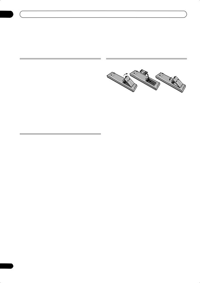
01 Before you start
Chapter 1:
Before you start
Checking what’s in the box
Please check that you’ve received the following supplied accessories:
•Setup microphone (cable: 5 m)
•Remote control unit
•AA/IEC R6P dry cell batteries x2
•AM loop antenna
•FM wire antenna
•Power cord
•Antenna adapter
•Flat-bladed converter plug
•These operating instructions
•Operating instructions for HOME MEDIA GALLERY (VSX-LX70 only)
Installing the receiver
•When installing this unit, make sure to put it on a level and stable surface.
Don’t install it on the following places:
–on a color TV (the screen may distort)
–near a cassette deck (or close to a device that gives off a magnetic field). This may interfere with the sound.
–in direct sunlight
–in damp or wet areas
–in extremely hot or cold areas
–in places where there is vibration or other movement
–in places that are very dusty
–in places that have hot fumes or oils (such as a kitchen)
6
Loading the batteries
 Caution
Incorrect use of batteries may result in such hazards as leakage and bursting. Observe the following precautions:
•Never use new and old batteries together.
•Insert the plus and minus sides of the batteries properly according to the marks in the battery case.
•Batteries with the same shape may have different voltages. Do not use different batteries together.
•Do not use or store batteries in direct sunlight or other excessively hot place, such as inside a car or near a heater. This can cause batteries to leak, overheat, explode or catch fire. It can also reduce the life or performance of batteries.
•When disposing of used batteries, please comply with governmental regulations or environmental public instruction’s rules that apply in your country or area.
En
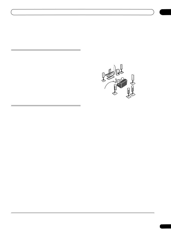
5 minute guide
Introduction to home theater
Home theater refers to the use of multiple audio tracks to create a surround sound effect, making you feel like you’re in the middle of the action or concert. The surround sound you get from a home theater system depends not only on your speaker setup, but also on the source and the sound settings of the receiver.
This receiver will automatically decode multichannel Dolby Digital, DTS, or Dolby Surround sources according to your speaker setup. In most cases, you won’t have to make changes for realistic surround sound, but other possibilities (like listening to a CD with multichannel surround sound) are explained in Listening to your system on page 29.
Listening to Surround Sound
This receiver was designed with the easiest possible setup in mind, so with the following quick setup guide, you should have your system hooked up for surround sound in no time at all. In most cases, you can simply leave the receiver in the default settings.
•Be sure to complete all connections before connecting this unit to an AC power source.
1 Connect your TV and DVD player.
See Connecting your TV and DVD player on page 14 to do this. For surround sound, you’ll want to hook up using a digital connection from the DVD player to the receiver.
2 Connect your speakers and place them for optimal surround sound.
Connect your speakers as shown in Installing your speaker system on page 19.
Where you place the speakers will have a big effect on the sound. Place your speakers as shown below for the best surround sound effect. Also see Placing the speakers on page 20 for more on this.
|
Center (C) |
Front |
|
|
Right (R) |
||
|
Front |
||
|
Left (L) |
Subwoofer (SW) |
Surround |
|
Right (SR) |
||
|
Surround |
||
|
Listening |
Back |
|
|
Right (SBR) |
||
|
position |
||
|
Surround |
||
|
Left (SL) |
||
|
Surround |
||
|
Back Left (SBL) |
3 Plug in the receiver and switch it on, followed by your DVD player, your subwoofer and the TV.
Plug the power cable into the AC outlet and switch on the
receiver.1 Make sure you’ve set the video input on your TV to this receiver. Check the manual that came with the TV if you don’t know how to do this.
• Set the subwoofer volume to a comfortable level.
4Use the on-screen automatic MCACC setup to set up your system.
See Automatically setting up for surround sound (MCACC & Full Band Phase Control) below for more on this.
5Play a DVD, and adjust the volume to your liking.
Make sure that DVD/LD is showing in the receiver’s display, indicating that the DVD input is selected. If it isn’t, press DVD on the remote control to set the receiver to the DVD input.
In addition to the basic playback explained in Playing a source on page 9, there are several other sound options you can select. See Listening to your system on page 29 for more on this.
See also Making receiver settings from the System Setup menu on page 37 for more setup options.
 Note
Note
1 After this receiver is connected to an AC outlet, a 15-second HDMI initialization process begins. You cannot carry out any operations during this process. The HDMI indicator in the front panel display blinks during this process, and you can turn on this receiver once it has stopped blinking. When you set the HDMI Control mode to OFF, you can skip this process. For details about the HDMI Control feature, see HDMI Control on page 62.
7
En
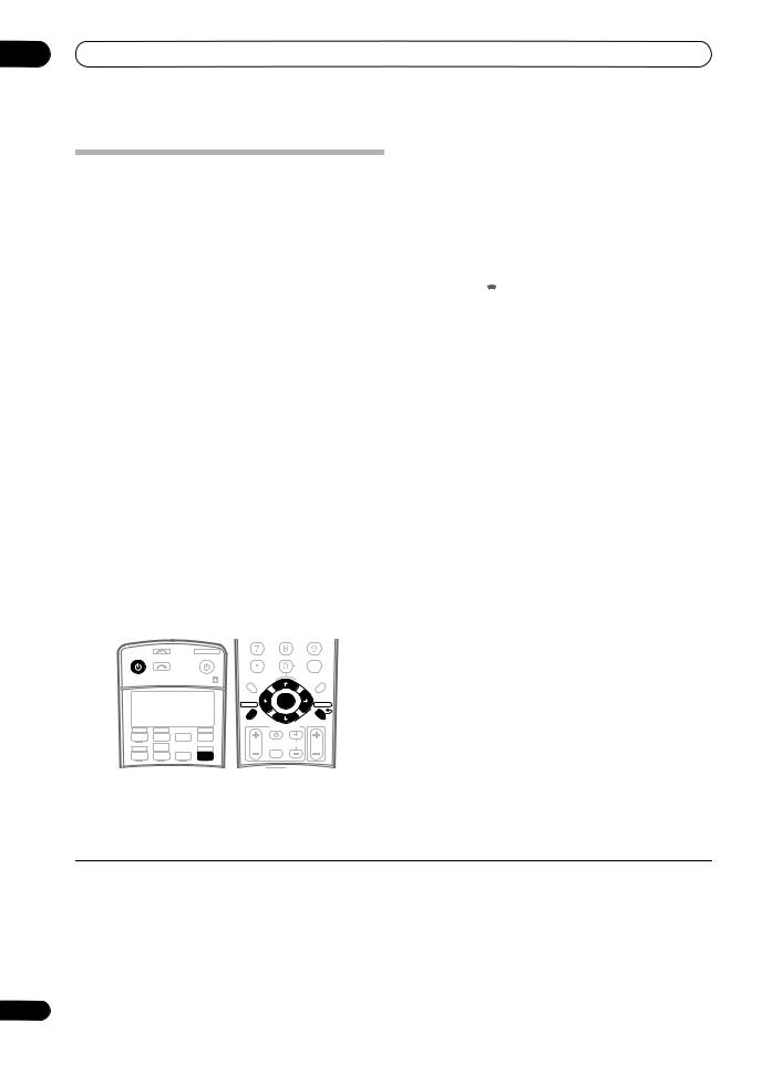
02 5 minute guide
Automatically setting up for surround sound (MCACC & Full Band Phase Control)
The Auto MCACC Setup measures the acoustic characteristics of your listening area, taking into account ambient noise, speaker size and distance, and tests for both channel delay and channel level. After you have set up the microphone provided with your system, the receiver uses the information from a series of test tones to optimize the speaker settings and equalization for your particular room, and also to calibrate the frequencyphase characteristics of the speakers connected.
2 Connect the microphone to the MCACC SETUP MIC jack on the front panel.
Place the microphone so that it’s about ear level at your normal listening position (use a tripod if possible). Make sure there are no obstacles between the speakers and the microphone.
•Push down on the lower portion of the front panel door to access the MCACC SETUP MIC jack:
|
AUDIO |
PARAMETER |
VIDEO |
MULTI – ZONE & |
SIGNAL |
SB ch |
STEREO/ |
||
|
(TUNE) |
SOURCE/REC SEL |
|||||||
|
SPEAKERS |
TUNER EDIT |
BAND |
CONTROL ON/OFF |
SELECT |
PROCESSING |
F.S.SURR |
||
|
PHONES |
MCACC |
VIDEO/GAME 2 INPUT |
||||||
|
(ST) |
ENTER |
(ST) |
USB |
SETUP MIC |
|
SETUP |
(TUNE) |
RETURN |
DIGITAL IN |
S-VIDEO |
VIDEO |
L AUDIO R |
The Auto MCACC display appears once the microphone
Make sure you do this before moving on to Playing a source on page 9.
 Important
•Make sure the microphone and speakers are not moved during the Auto MCACC Setup.
•Using the Auto MCACC Setup will overwrite any existing settings for the MCACC preset you select.
•Before using the Auto MCACC Setup, the headphones should be disconnected and the iPod or HOME MEDIA GALLERY (VSX-LX70 only) function should not be selected as an input source.
 Caution
•The test tones used in the Auto MCACC Setup are output at high volume.
|
INPUT |
SYSTEM OFF |
||||||
|
RECEIVER |
SOURCE |
D.ACCESS |
CLASS |
||||
|
SELECT |
CLEAR |
DISC |
|||||
|
+10 |
CH |
ENTER |
|||||
|
LEVEL |
|||||||
|
A PARAMETER |
V PARAMETER |
||||||
|
TOP MENU |
MENU T.EDIT |
||||||
|
TUNE |
|||||||
|
BAND |
ST |
ST |
|||||
|
ENTER |
|||||||
|
SETUP |
RETURN |
||||||
|
TUNE |
|||||||
|
PROGRAM |
TV CONTROL |
||||||
|
CD |
CD-R |
HDMI |
|||||
|
DVD |
TV |
BD |
TVCTRL |
||||
|
HOME MEDIA |
TVVOL |
INPUT |
TV CH |
VOL |
|||
|
DVR2 |
ZONE2/3 |
SELECT |
|||||
|
GALLERY |
|||||||
|
DVR1 |
iPod |
TUNER |
RECEIVER |
1 Switch on the receiver and your TV.
is connected.1
|
DVD/LD |
— 55.0dB |
|||||
|
1. Auto MCACC |
||||||
|
Surr Back System |
||||||
|
[Normal (default)] |
||||||
|
Save SYMMETRY to |
||||||
|
[M1. MEMORY |
1 |
] |
||||
|
START |
||||||
|
ENTER:Start |
:Cancel |
|||||
3Make sure ‘Normal (default)’ is selected,2 select an MCACC preset3 then select START.4
4Follow the instructions on-screen.
Make sure the microphone is connected, and if you’re using a subwoofer, make sure it is switched on and set to a comfortable volume level.
5 Wait for the test tones to finish then confirm the speaker configuration in the OSD.
A progress report is displayed on-screen while the receiver outputs test tones to determine the speakers present in your setup. Try to be as quiet as possible while
it’s doing this.5
If no operations are performed for 10 seconds while the speaker configuration check screen is being displayed, the Auto MCACC Setup will resume automatically. In this case, you don’t need to select ‘OK’ and press ENTER in step 6.
 Note
Note
1• You can’t use the System Setup menu in either the main or sub zone when the iPod or HOME MEDIA GALLAERY (VSX-LX70 only) input source is selected. When you set ZONE 2 or ZONE 3 to ON (page 58), you can’t use the System Setup menu.
•If you cancel the Auto MCACC Setup, or leave an error message for over three minutes, the screen saver will appear.
2• If you are planning on bi-amping your front speakers, or setting up a separate speaker system in another room, read through Surround back speaker setting on page 40 and make sure to connect your speakers as necessary before continuing to step 4.
•If you have THX-certified speakers, select CUSTOM and choose YES for the THX Speaker setting.
3The six MCACC presets are used for storing surround sound settings for different listening positions. Simply choose an unused preset for now (you can rename it later in Data Management on page 46).
4Note that correction curves are saved only when set to SYMMETRY. Select CUSTOM to save other correction curves (such as ALL CH ADJUST and FRONT ALIGN). See Automatic MCACC (Expert) on page 37 for more on this.
5Do not adjust the volume during the test tones. This may result in incorrect speaker settings.
8
En
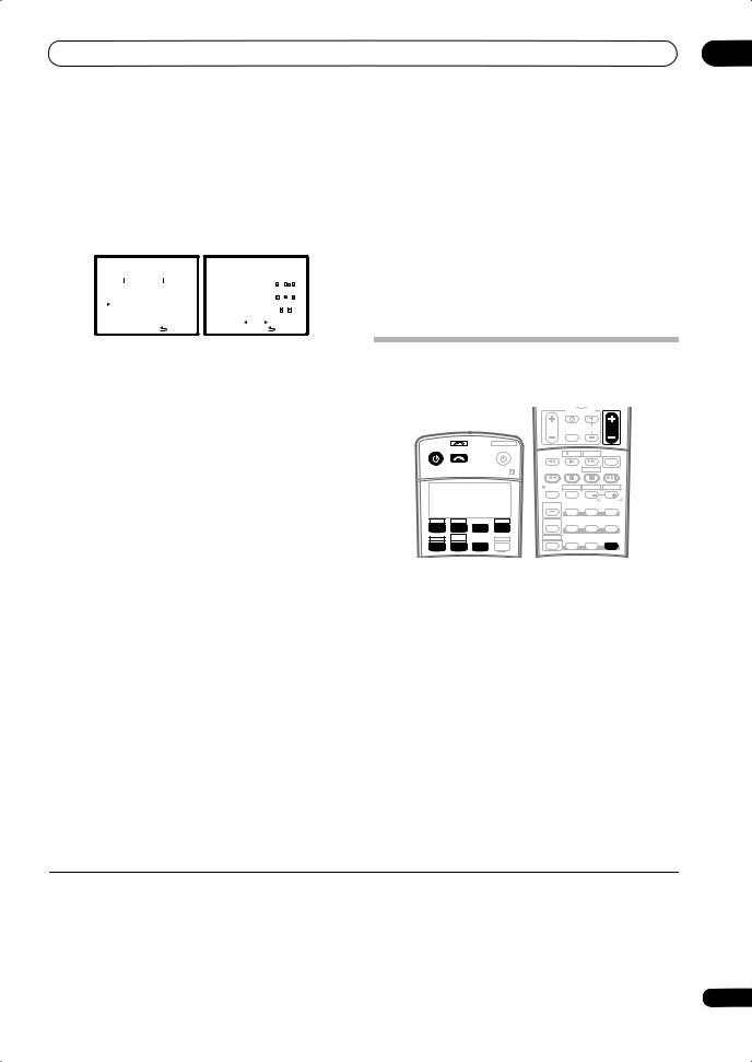
•With error messages (such as Too much ambient noise! or Check Microphone) select RETRY after checking for ambient noise (see Problems when using the Auto MCACC Setup below) and verifying the mic connection. If there doesn’t seem to be a problem, you can simply select GO NEXT and continue.
|
DVD/LD |
0.0dB |
DVD/LD |
0.0dB |
|||||||||
|
1. Auto MCACC |
1. Auto MCACC |
|||||||||||
|
Now Analyzing… |
( 2/11) |
CHECK |
||||||||||
|
Front |
[ YES ] |
|||||||||||
|
Center |
[ YES ] |
|||||||||||
|
Environment Check |
Surr |
[ YES ] |
||||||||||
|
Ambient Noise |
[ OK ] |
SB |
[ YESx2] |
|||||||||
|
Microphone |
[ |
] |
SW |
[ YES ] |
||||||||
|
Speaker YES/NO |
[ |
] |
||||||||||
|
:Cancel |
10:Next |
OK |
:Cancel |
|||||||||
The configuration shown on-screen should reflect the actual speakers you have.1
If you see an error message (ERR) in the right side column (or the speaker configuration displayed isn’t correct), there may be a problem with the speaker connection. If selecting RETRY doesn’t work, turn off the power and check the speaker connections. If there doesn’t seem to be a problem, you can simply use / to select the speaker and / to change the setting (and number for surround back) and continue.
6 Make sure ‘OK’ is selected, then press ENTER.
A progress report is displayed on-screen while the receiver outputs more test tones to determine the optimum receiver settings for Channel Level, Speaker Distance, Standing Wave, Acoustic Cal EQ and Full Band Phase Control.
Again, try to be as quiet as possible while this is happening. It may take 3 to 7 minutes.
7 The Auto MCACC Setup has finished! Press RETURN
to go back to the System Setup menu.2
Be sure to disconnect the microphone from this receiver upon completion of the Auto MCACC setup.
The settings made in the Auto MCACC Setup should give you excellent surround sound from your system, but it is also possible to adjust these settings manually using the
System Setup menu (starting on page 37).3
Problems when using the Auto MCACC Setup
If the room environment is not optimal for the Auto MCACC Setup (too much background noise, echo off the walls, obstacles blocking the speakers from the microphone) the final settings may be incorrect. Check for household appliances (air conditioner, fridge, fan, etc.), that may be affecting the environment and switch them off if necessary. If there are any instructions showing in the front panel display, please follow them.
•Some older TVs may interfere with the operation of the microphone. If this seems to be happening, switch off the TV when doing the Auto MCACC Setup.
Playing a source
Here are the basic instructions for playing a source (such as a DVD disc) with your home theater system.
|
TV CONTROL |
||||||||
|
TVVOL |
INPUT |
TV CH |
VOL |
|||||
|
SELECT |
||||||||
|
INPUT |
SYSTEM OFF |
|||||||
|
RECEIVER |
SOURCE |
|||||||
|
SELECT |
TV/DTV |
REC |
INFO |
|||||
|
MUTE |
||||||||
|
MPX |
REC STOP |
JUKEBOX |
||||||
|
AUDIO |
SUBTITLE |
HDD |
DVD |
|||||
|
DISP |
CH |
CH |
||||||
|
PHOTO |
T.DISP |
STEREO/ |
||||||
|
STATUS |
SIGNAL SEL |
SBch |
F.S.SURR |
|||||
|
CD |
CD-R |
HDMI |
MULTI OPE |
THX |
STANDARD |
ADV.SURR |
||
|
DVD |
TV |
BD |
TVCTRL |
|||||
|
DVR2 |
HOME MEDIA |
ZONE2/3 |
SHIFT |
PHASE |
MCACC |
S.DIRECT |
||
|
GALLERY |
||||||||
|
DVR1 |
iPod |
TUNER |
RECEIVER |
1 Switch on your system components and receiver.
Start by switching on the playback component (for
example a DVD player), your TV4 and subwoofer (if you have one), then the receiver (press RECEIVER).
• Make sure the setup mic is disconnected.
2 Select the input source you want to play.
You can use the input source buttons on the remote control, INPUT SELECT, or the front panel INPUT
SELECTOR dial.5
 Note
Note
1If you’re using the front panel display, the diagram in Listening to Surround Sound above indicates (in bold) how each speaker is displayed.
2You can also choose to view the settings from the MCACC Data Check screen. See Automatic MCACC (Expert) on page 37 for more on this.
3• Depending on the characteristics of your room, sometimes identical speakers with cone sizes of around 12 cm will end up with different size settings. You can correct the setting manually using the Manual speaker setup on page 48.
•The subwoofer distance setting may be farther than the actual distance from the listening position. This setting should be accurate (taking delay and room characteristics into account) and generally does not need to be changed.
4Make sure that the TV’s video input is set to this receiver (for example, if you connected this receiver to the VIDEO 1 jacks on your TV, make sure that the VIDEO 1 input is now selected).
5If you need to manually switch the input signal type press SIGNAL SEL (page 32).
9
En
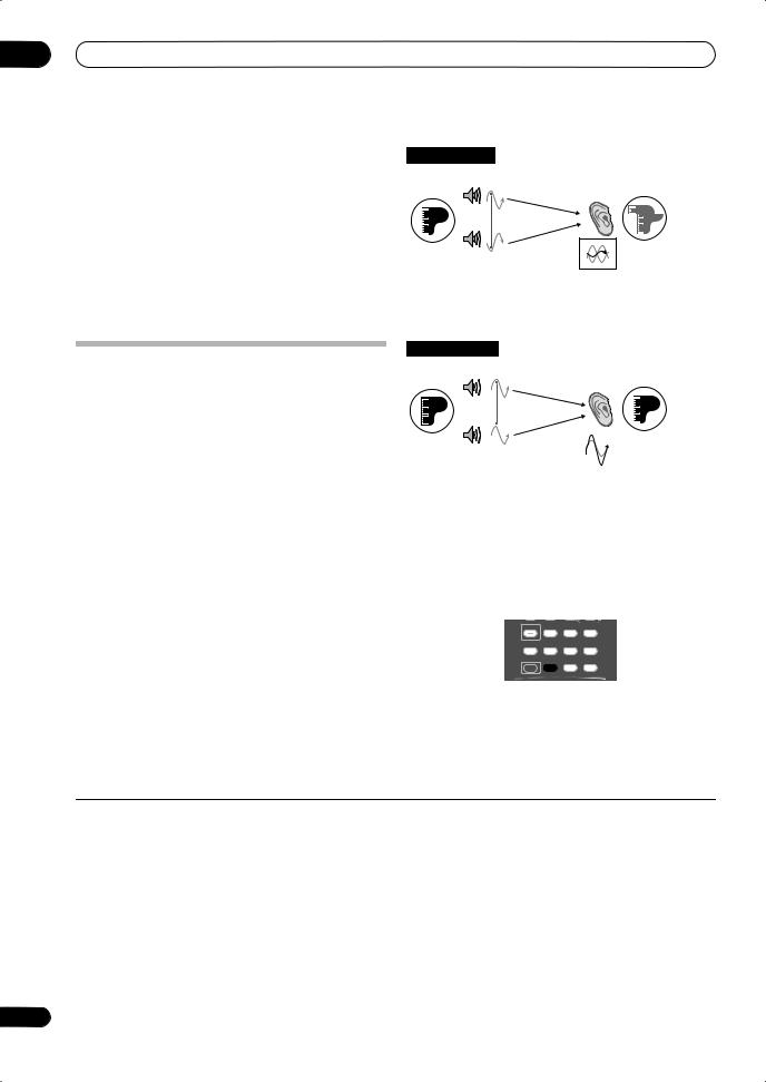
02 5 minute guide
3 Press S.DIRECT (STREAM DIRECT) to select ‘AUTO
SURROUND’ and start playback of the source.1
If you’re playing a Dolby Digital or DTS surround sound DVD disc, you should hear surround sound. If you are playing a stereo source, you will only hear sound from the front left/right speakers in the default listening mode.
•See also Listening to your system on page 29 for information on different ways of listening to sources.
4 Use the volume control to adjust the volume level.
Turn down the volume of your TV so that all sound is coming from the speakers connected to this receiver.
Better sound using Phase Control and Full Band Phase Control
This receiver is equipped with the two types of functions that correct phase distortion and group delay: Phase Control and Full Band Phase Control. Activating Full Band Phase Control is strongly recommended because it also involves the effects of Phase Control. For details on each of these two features, refer to the following explanations.
Using Phase Control
During multichannel playback, LFE (Low-Frequency Effects) signals as well as low-frequency signals in each channel are assigned to the subwoofer or other the subwoofer and the most appropriate speaker. At least in theory, however, this type of processing involves a group delay that varies with frequency, resulting in phase distortion where the low-frequency sound is delayed or muffled by the conflict with other channels. With the Phase Control mode switched on, this receiver can reproduce powerful bass sound without deteriorating the quality of the original sound (see illustration below).
|
Phase Cotrol OFF |
|||
|
Front speaker |
Listening |
||
|
position |
|||
|
Sound |
Sound muffled due |
||
|
Subwoofer |
to a delay in time |
||
|
source |
|||
•Rhythms blurred and difficult to hear
•Bass sound with loss of depth
•Sound of musical instruments with no reality
|
Phase Control ON |
|||
|
Front speaker |
Listening |
||
|
position |
|||
|
Sound |
Original sound |
||
|
Subwoofer |
preserved with |
||
|
source |
|||
|
no loss of clarity |
|||
•Rhythms with crystal-like clarity
•Bass sound with no loss of depth
•Sound of musical instruments with superb reality Phase Control technology provides coherent sound
reproduction through the use of phase matching2 for an optimal sound image at your listening position. The default setting is on and we recommend leaving Phase Control switched on for all sound sources.
|
PHOTO |
T.DISP |
STEREO/ |
|
|
STATUS |
SIGNAL SEL SBch |
F.S.SURR |
|
|
MULTI OPE |
THX |
STANDARD |
ADV. SURR |
SHIFT PHASE MCACC S.DIRECT
• Press PHASE (PHASE CONTROL) to select PHASE CONTROL.
The PHASE CONTROL indicator on the front panel lights.
 Note
Note
1• You may need to check the digital audio output settings on your DVD player or digital satellite receiver. It should be set to output Dolby Digital, DTS and 88.2 kHz / 96 kHz PCM (2 channel) audio, and if there is an MPEG audio option, set this to convert the MPEG audio to PCM.
•Depending on your DVD player or source discs, you may only get digital 2 channel stereo and analog sound. In this case, the receiver must be set to a multichannel listening mode (see Listening in surround sound on page 29 if you need to do this) if you want multichannel surround sound.
2• Phase matching is a very important factor in achieving proper sound reproduction. If two waveforms are ‘in phase’, they crest and trough together, resulting in increased amplitude, clarity and presence of the sound signal. If a crest of a wave meets a trough (as shown in the upper section of the diagram above) then the sound will be ‘out of phase’ and an unreliable sound image will be produced.
•The PHASE CONTROL feature is available even when the headphones are plugged in.
•If your subwoofer has a phase control switch, set it to the plus (+) sign (or 0˚). However, the effect you can actually feel when PHASE CONTROL is set to ON on this receiver depends on the type of your subwoofer. Set your subwoofer to maximize the effect. It is also recommended you try changing the orientation or the place of your subwoofer.
•Set the built-in lowpass filter switch of your subwoofer to OFF. If this cannot be done on your subwoofer, set the cutoff frequency to a higher value.
•If the speaker distance is not properly set, you may not have a maximized PHASE CONTROL effect.
•The PHASE CONTROL mode cannot be set to ON in the following cases:
–When the PURE DIRECT mode is switched on.
–When MULTI CH IN is selected.
–When the HDMI audio output parameter is set to THROUGH in Setting the Audio options.
10
En
![]()
Using Full Band Phase Control
The Full Band Phase Control feature calibrates the frequency-phase characteristics of the speakers connected.
Standard speakers designed exclusively for audio use generally reproduce sound with the divided frequency bands output from a speaker system consisting of multiple speakers (in case of typical 3-way speakers, for instance, the tweeter, the squawker (midrange), and the woofer output sound in the high-, middle-, and lowfrequency ranges, respectively). Though these speakers are designed to flatten the frequency-amplitude characteristics across wide ranges, there are cases where the group delay characteristics are not effectively flattened. This phase distortion of the speakers subsequently causes group delay (the delay of lowfrequency sound against high-frequency sound) during audio signal playback.
This receiver analyzes the frequency-phase characteristics of the speakers by calibrating test signals output from the speakers with the supplied microphone, therefore flattening the analyzed frequency-phase
characteristics during audio signal playback1 – the same correction is made for a pair of left and right speakers. This correction minimizes group delay between the ranges of a speaker and improves the frequency-phase characteristics across all ranges.
Furthermore, the enhanced frequency-phase characteristics between channels ensure better
surround sound integration for multichannel setting.2
Full Band Phase Control OFF
Tweeter
Midrange
Woofer
Group Delay Characteristics
ms
Hz
Sound in the middleand low-frequency ranges is delayed against the high-frequency sound due to group delay.
Full Band Phase Control ON
Tweeter
Midrange
Woofer
Group Delay Characteristics
ms
Hz
With the phase distortion corrected, the frequency-phase characteristics are improved across all ranges.
•Sound with live dynamics
•Sound of musical instruments with superb reality
•Sound so accurately reproduced that you can even hear the lip movement of the singer
•Speech heard with no loss of clarity
•Surround sound with excellent integration
|
PHOTO |
T.DISP |
STEREO/ |
|
|
STATUS |
SIGNAL SEL SBch |
F.S.SURR |
|
|
MULTI OPE |
THX |
STANDARD |
ADV. SURR |
SHIFT PHASE MCACC S.DIRECT
•Press PHASE (PHASE CONTROL) to select FULLBAND PHASE.3
Both the Phase Control and Full Band Phase Control functions are switched on. The FULL BAND PHASE CTRL indicator lights on the front panel display.
 Note
Note
1To calibrate and analyze the frequency-phase characteristics of the speakers, follow the procedures in Auto MCACC (see Automatically setting up for surround sound (MCACC & Full Band Phase Control) on page  or FULL BAND PHASE CTRL in the System Setup (see Full Band Phase Control on page 45). Select ALL when you perform the Auto MCACC setup with CUSTOM. Upon calibration of the frequency-phase characteristics of the speakers, the FULL BAND PHASE CTRL feature is automatically switched on. Note that FULLBAND PHASE cannot be selected unless the frequency-phase characteristics of the speakers are calibrated.
2The original characteristics of group delay of the speakers calibrated and the targeted characteristics after correction can be displayed graphically in the OSD (see Full Band Phase Control on page 45). Also, when your PC is connected to this receiver, the original characteristics of group delay of the speakers calibrated and the corrected characteristics of group delay can be displayed in 3-dimension on your PC (see Advanced MCACC output using your PC on page 61).
3• The FULL BAND PHASE CTRL mode cannot be set to ON in the following cases:
–When headphones are plugged in.
–When the PURE DIRECT mode is switched on.
–When MULTI CH IN is selected.
–When the HDMI audio output parameter is set to THROUGH in Setting the Audio options.
11
En
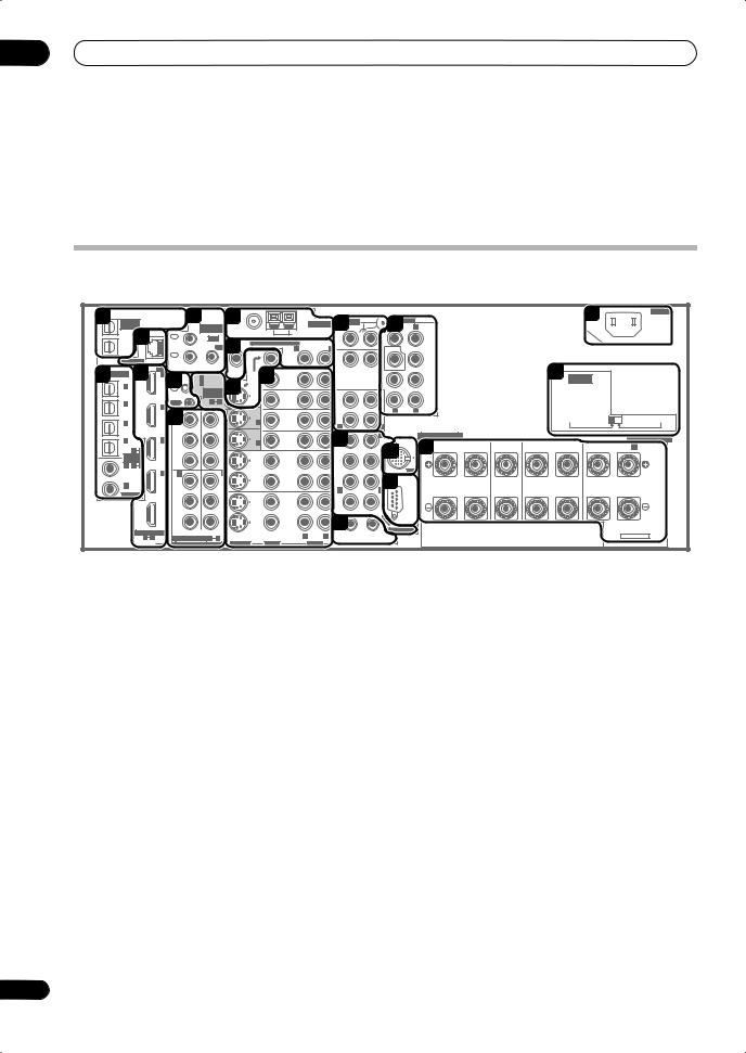
03 Connecting your equipment
Chapter 3:
Connecting your equipment
This receiver provides you with many connection possibilities, but it doesn’t have to be difficult. This page explains the kinds of components you can connect to make up your home theater system.
Rear panel
This illustration shows the VSX-LX70, however connections for the LX60 are the same except where noted.
|
1 |
5 |
8 |
19 |
AC IN |
|||||||||||||||||||||||
|
MULTI-ZONE |
ANTENNA |
AUDIO |
PRE OUT |
||||||||||||||||||||||||
|
& SOURCE |
MULTI-ZONE |
PHONO |
R |
L |
|||||||||||||||||||||||
|
/REC SEL |
FRONT |
||||||||||||||||||||||||||
|
OUT1 |
3 |
& SOURCE |
FM UNBAL 75 Ω |
AM LOOP |
12 |
15 |
|||||||||||||||||||||
|
IN |
|||||||||||||||||||||||||||
|
ZONE3 |
IR |
IN |
|||||||||||||||||||||||||
|
1 |
ZONE2 MULTI-ZONE & SOURCE |
ZONE2 |
|||||||||||||||||||||||||
|
OUT2 |
|||||||||||||||||||||||||||
|
MAIN |
OUT |
9 |
R |
L |
SUBW. |
CENTER |
|||||||||||||||||||||
|
CD |
|||||||||||||||||||||||||||
|
IN |
OUT |
IN |
|||||||||||||||||||||||||
|
LAN (10/100) |
2 |
20 VOLTAGE |
|||||||||||||||||||||||||
|
2 |
4 |
HDMI |
ZONE2 |
MONI- |
11 |
SUR- |
|||||||||||||||||||||
|
OPTICAL |
MONI- |
ROUND |
|||||||||||||||||||||||||
|
IN 1 |
IN 1 (DVD/LD) |
TOR |
|||||||||||||||||||||||||
|
CONTROL |
OUT |
TOR |
DVD/LD |
||||||||||||||||||||||||
|
IN 1 |
6 |
IN 2 (BD) |
10 |
OUT |
IN |
SUR- |
SELECTOR |
||||||||||||||||||||
|
(TV/SAT) |
IN |
ASSIGN- |
OUT |
ROUND |
|||||||||||||||||||||||
|
BACK |
|||||||||||||||||||||||||||
|
ABLE |
BD |
||||||||||||||||||||||||||
|
IN 2 |
IN 2 |
OUT |
1 |
2 |
IN |
CD-R/ |
(Single) |
||||||||||||||||||||
|
(BD) |
R |
L |
|||||||||||||||||||||||||
|
IN 1 |
OUT |
TAPE |
|||||||||||||||||||||||||
|
TV/SAT |
MD |
220V |
230 — 240V |
||||||||||||||||||||||||
|
7Y |
Y |
IN 1 |
IN |
||||||||||||||||||||||||
|
IN 3 |
IN |
L |
|||||||||||||||||||||||||
|
(DVR/ |
(DVD/ |
R |
|||||||||||||||||||||||||
|
VCR 1) |
LD) |
R |
L |
SPEAKERS |
|||||||||||||||||||||||
|
IN 4 |
IN 3 |
PB |
PB |
VIDEO / |
13 |
FRONT |
SPEAKERS |
||||||||||||||||||||
|
IN 2 |
GAME 1 |
||||||||||||||||||||||||||
|
IN |
A |
FRONT |
CENTER |
SURROUND |
SURROUND BACK / |
B |
|||||||||||||||||||||
|
(CD-R) |
4 |
IN |
SUBW. |
CENTER |
L |
R |
L |
R |
L(Single) |
||||||||||||||||||
|
1 |
18 R |
||||||||||||||||||||||||||
|
ASSIGN- |
16 |
||||||||||||||||||||||||||
|
ABLE |
PR |
PR |
OUT |
||||||||||||||||||||||||
|
IN 1 |
1 |
2 |
DVR/ |
SUR- |
|||||||||||||||||||||||
|
(DVD/ |
iPod |
||||||||||||||||||||||||||
|
IN 4 |
IN 2 |
IN 3 |
VCR 1 |
ROUND |
|||||||||||||||||||||||
|
LD) |
17 |
||||||||||||||||||||||||||
|
IN 2 (CD) |
Y |
Y |
IN |
||||||||||||||||||||||||
|
(BD) |
R |
L |
|||||||||||||||||||||||||
|
COAXIAL |
|||||||||||||||||||||||||||
|
OUT |
PB |
PB |
OUT |
||||||||||||||||||||||||
|
DVR/ |
|||||||||||||||||||||||||||
|
SURROUND BACK |
|||||||||||||||||||||||||||
|
VCR 2 |
|||||||||||||||||||||||||||
|
PR |
PR |
IN |
141 |
RS-232C |
|||||||||||||||||||||||
|
ASSIGNABLE |
(VIDEO/GAME 1) |
2 |
MULTI CH IN |
||||||||||||||||||||||||
|
R |
L |
12 V TRIGGER |
SELECTABLE |
||||||||||||||||||||||||
|
1 |
4 |
ASSIGNABLE |
1 |
3 |
(DC OUT 12V/ |
||||||||||||||||||||||
|
TOTAL 50 mA MAX) |
|||||||||||||||||||||||||||
|
DIGITAL |
COMPONENT VIDEO |
S-VIDEO |
VIDEO |
AUDIO |
|||||||||||||||||||||||
 Caution
•Before making or changing the connections, switch off the power and disconnect the power cord from the power outlet. Plugging in should be the final step.
1 Optical digital audio output(s)
Use the OUT1 and (VSX-LX70 only) OUT2 jack for recording to a CD or MiniDisc recorder.
See Connecting digital audio sources on page 17.
The OUT1 jack is also used for MULTI-ZONE connections.
See MULTI-ZONE listening on page 56.
2Optical and coaxial digital audio inputs (x6)
Use for digital audio sources, including DVD players/ recorders, digital satellite receivers, CD players, etc.
See also The Input Setup menu on page 64 to assign the inputs.
3LAN (10/100) terminal (VSX-LX70 only)
For details, refer to the supplied operating instructions for HOME MEDIA GALLERY.
4HDMI connectors (x4) (VSX-LX60) (x5) (VSX-LX70)
Multiple inputs and one output for high-quality audio/ video connection to compatible HDMI devices.
See Connecting using HDMI on page 52.
5 Remote inputs (MULTI-ZONE and source)
Use for connection to an external remote control sensor for use in a MULTI-ZONE setup, for example.
See Connecting an IR receiver on page 58.
6 Control input/output
Use to connect other Pioneer components so that you can control all your equipment from a single IR remote sensor.
See Operating other Pioneer components with this unit’s sensor on page 79.
7 Component video connections (x4)
Use the inputs to connect any video source that has component video output, such as a DVD recorder. Use the output for connection to a monitor or TV.
See Using the component video jacks on page 16.
8 AM and FM antenna terminals
Use to connect indoor or outdoor antennas for radio broadcasts.
See Connecting antennas on page 21.
9 MULTI-ZONE and source outputs
Use to connect a second amplifier in a separate room.
See MULTI-ZONE listening on page 56.
10 Composite and S-video monitor outputs
Use to connect monitors and TVs.
See Connecting your TV and DVD player on page 14.
12
En
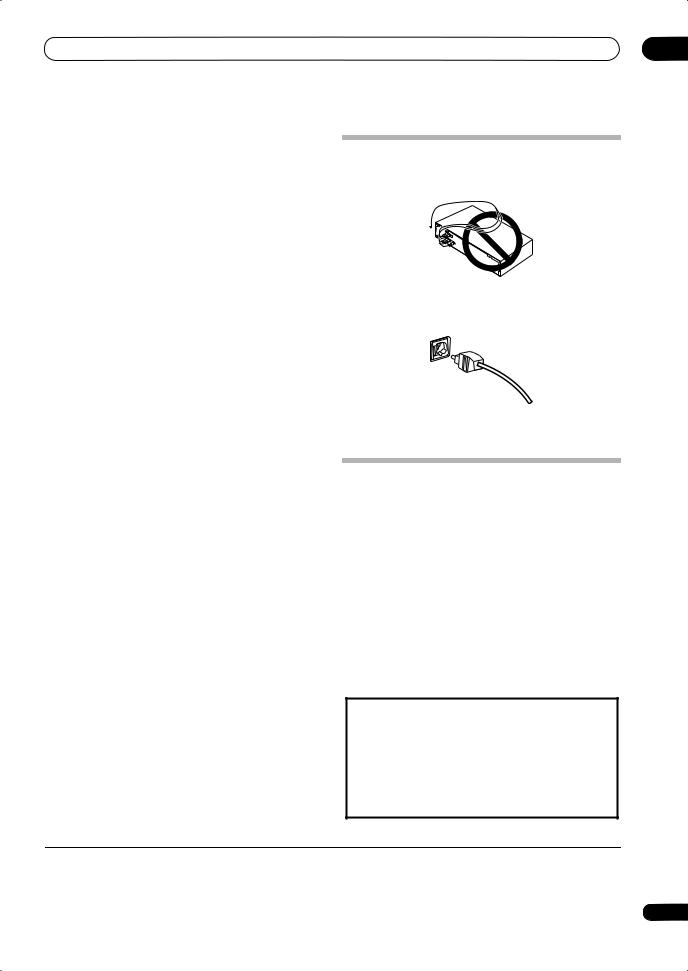
Connecting your equipment
11 Audio/video source inputs/(outputs) (x6)
Use for connection to audio/visual sources, such as DVD players/recorders, VCRs, etc. Each set of inputs has jacks
for composite video, S-video1 and stereo analog audio.
See Connecting a DVD/HDD recorder, VCR and other video sources on page 16.
12 Stereo analog audio source inputs/(outputs) (x3)
03
When making cable connections
•To avoid hum, do not lay connected cables over the top of the receiver.
Use for connection to audio sources such as CD players, tape decks, turntables, etc.
See Connecting analog audio sources on page 18.
13 Multichannel analog audio inputs
7.1 channel inputs for connection to a DVD player with multichannel analog outputs.
See Connecting the multichannel analog inputs on page 53.
14 12 V trigger jacks (total 50 mA max.) (x2)
Use to switch components in your system on and off according to the input function of the receiver.
See Switching components on and off using the 12 volt trigger on page 59.
15 Multichannel pre-amplifier outputs
Use to connect separate amplifiers for center, surround, surround back and subwoofer channels.
See Connecting additional amplifiers on page 56 (see also Installing your speaker system on page 19 for powered subwoofer connection).
16 iPod input terminal
Use to connect your Apple iPod as an audio or video source.
See Connecting an iPod on page 51.
17 RS-232C connector
Use for connection to a PC for graphical output when using Advanced MCACC or Full Band Phase Control.
See Connecting a PC for Advanced MCACC output on page 61.
18 Speaker terminals
Use for connection to the main front, center, surround and surround back speakers.
See Installing your speaker system on page 19.
19 AC IN inlet
Connect the supplied power cord here.
See Plugging in the receiver on page 23.
20 Voltage selector switch
Use these to match the voltage coming into the receiver with the voltage in your country or region.
Voltage selector on page 3.
•When connecting optical cables, be careful when inserting the plug not to damage the shutter protecting the optical socket.
•When storing optical cable, coil loosely. The cable may be damaged if bent around sharp corners.
About the video converter
The video converter ensures that all video sources are output through all of the MONITOR VIDEO OUT jacks. The only exception is HDMI and high-definition component video: since these resolutions cannot be downsampled, you must connect your monitor/TV to the receiver’s HDMI/component video outputs when
connecting these video sources.2
If several video components are assigned to the same input function (see The Input Setup menu on page 64), the converter gives priority to HDMI, component, S-video, then composite (in that order).
•For optimal video performance, THX recommends switching Digital Video Conversion (in Setting the Video options on page 69) OFF.
This product incorporates copyright protection technology that is protected by method claims of certain U.S. patents and other intellectual property rights owned by Macrovision Corporation and other rights owners. Use of this copyright protection technology must be authorized by Macrovision Corporation, and is intended for home and other limited viewing uses only unless otherwise authorized by Macrovision Corporation. Reverse engineering or disassembly is prohibited.
 Note
Note
1You must assign the input source to the S-video input to which you’ve connected your video component (see The Input Setup menu on page 64).
2If the video signal does not appear on your TV or plasma display, try adjusting the resolution settings on your component or display. Note that some components (such as video game units) have resolutions that may not be converted. In this case, try switching Digital Video Conversion (in Setting the Video options on page 69) OFF.
13
En
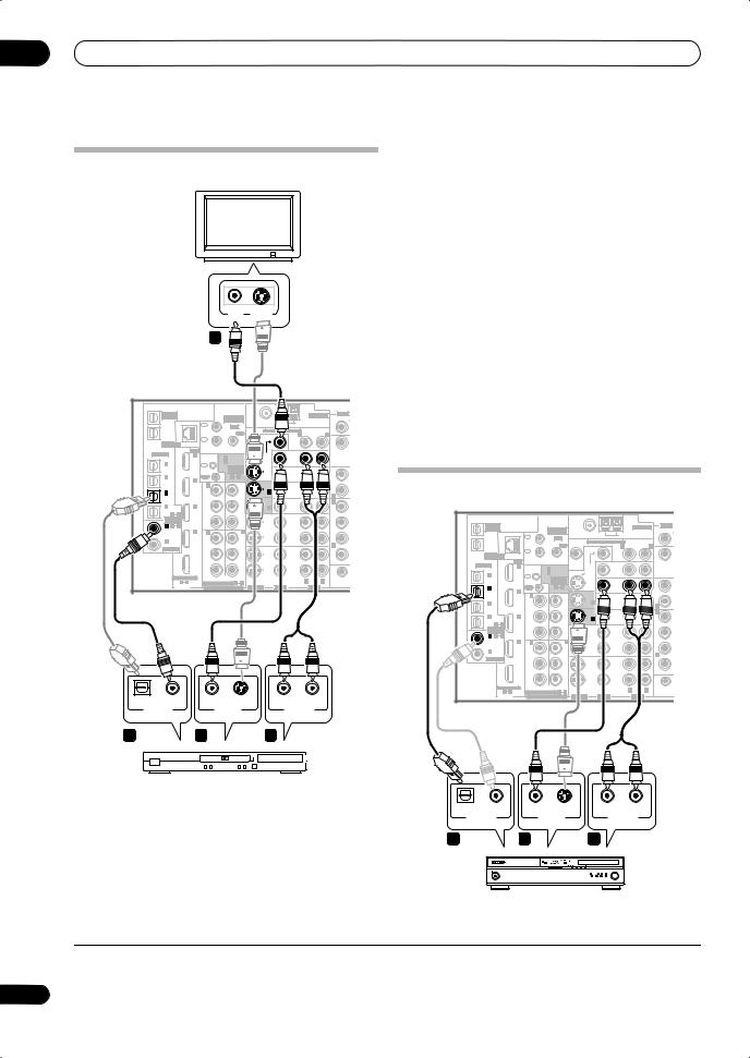
03 Connecting your equipment
Connecting your TV and DVD player
TV
1Connect the MONITOR OUT video jack to a video input on your TV.
Use a standard RCA/phono jack video cable to connect to the composite video jack, or for higher quality video, use an S-video cable to connect to the S-video jack.
2Connect a composite or S-video output on your DVD player to the DVD/LD VIDEO or DVD/LD S-VIDEO input.
Connect using a standard video cable or an S-video cable.
|
VIDEO |
S-VIDEO |
3 Connect a coaxial-type1 digital audio output on |
||||||||||||||||
|
IN |
IN |
your DVD player to the COAXIAL IN 1 (DVD/LD) input. |
||||||||||||||||
|
1 |
||||||||||||||||||
|
Use a coaxial cable designed for digital audio. |
||||||||||||||||||
|
4 Connect the stereo audio outputs on your DVD |
||||||||||||||||||
|
player to the DVD/LD AUDIO inputs. |
||||||||||||||||||
|
Connect using a stereo RCA/phono jack cable. |
||||||||||||||||||
|
& SOURCE |
ANTENNA |
AUDIO |
• If your DVD player has multichannel analog outputs, |
|||||||||||||||
|
MULTI-ZONE |
||||||||||||||||||
|
/REC SEL |
MULTI-ZONE |
PHONO |
you can connect these instead. See also Connecting |
|||||||||||||||
|
OUT1 |
1 |
& SOURCE |
ZONE2 |
MULTI-ZONE & SOURCE |
ZONE2 |
IN |
||||||||||||
|
ZONE3 |
IN |
IR |
||||||||||||||||
|
OUT2 |
MAIN |
OUT |
R |
L |
the multichannel analog inputs on page 53. |
|||||||||||||
|
LAN (10/100) |
IN |
|||||||||||||||||
|
2 |
OUT |
|||||||||||||||||
|
IN |
CD |
|||||||||||||||||
|
HDMI |
ZONE2 |
MONI- |
||||||||||||||||
|
OPTICAL |
IN 1 |
IN 1 (DVD/LD) |
TOR |
MONI- |
||||||||||||||
|
CONTROL |
OUT |
TOR |
DVD/LD |
|||||||||||||||
|
IN 2 (BD) |
OUT |
IN |
||||||||||||||||
|
IN 1 |
IN |
|||||||||||||||||
|
(TV/SAT) |
ASSIGN- |
OUT |
||||||||||||||||
|
ABLE |
BD |
|||||||||||||||||
|
IN 2 |
IN 2 |
OUT |
1 2 |
IN 1 |
IN |
R |
Connecting your Blu-ray disc player |
|||||||||||
|
IN 3 |
IN |
|||||||||||||||||
|
(BD) |
CD-R/ |
|||||||||||||||||
|
IN 1 |
OUT |
TAPE/ |
||||||||||||||||
|
Y |
Y |
TV/SAT |
IN |
|||||||||||||||
|
(DVR/ |
(DVD/ |
|||||||||||||||||
|
VCR 1) |
LD) |
VIDEO / |
R |
|||||||||||||||
|
IN 4 |
IN 3 |
PB |
PB |
|||||||||||||||
|
IN 2 |
GAME 1 |
|||||||||||||||||
|
(CD-R) |
IN |
SUBW. |
||||||||||||||||
|
1 |
4 |
|||||||||||||||||
|
ASSIGN- |
||||||||||||||||||
|
ABLE |
PR |
PR |
OUT |
MULTI-ZONE |
AUDIO |
|||||||||||||
|
IN 1 1 |
2 |
ANTENNA |
||||||||||||||||
|
(DVD/ |
DVR/ |
SUR- |
& SOURCE |
MULTI-ZONE |
PHONO |
|||||||||||||
|
LD) |
IN 4 |
IN 2 |
IN 3 |
VCR 1 |
OUT1 |
IN |
& SOURCE |
FM UNBAL 75 Ω |
AM LOOP |
|||||||||
|
Y |
Y |
IN |
ZONE3 |
IR |
IN |
|||||||||||||
|
IN 2 (CD) |
1 |
ZONE2 MULTI-ZONE & SOURCE |
ZONE2 |
|||||||||||||||
|
OUT2 |
||||||||||||||||||
|
COAXIAL |
(BD) |
R |
MAIN |
OUT |
R |
L |
CD |
|||||||||||
|
IN |
||||||||||||||||||
|
PB |
PB |
OUT |
IN |
|||||||||||||||
|
OUT |
LAN (10/100) |
2 |
OUT |
|||||||||||||||
|
DVR/ |
ZONE2 |
|||||||||||||||||
|
SURROU |
HDMI |
MONI- |
||||||||||||||||
|
VCR 2 |
OPTICAL |
IN 1 |
MONI- |
|||||||||||||||
|
CONTROL IN 1 (DVD/LD) |
TOR |
|||||||||||||||||
|
PR |
PR |
IN |
OUT |
TOR |
DVD/LD |
|||||||||||||
|
IN 2 (BD) |
OUT |
IN |
||||||||||||||||
|
ASSIGNABLE |
1 |
IN 1 |
IN |
|||||||||||||||
|
(VIDEO/GAME 1) |
R |
L |
12 V TR |
(TV/SAT) |
ASSIGN- |
OUT |
||||||||||||
|
1 4 |
ASSIGNABLE 1 3 |
(DC OUT 12V/ |
ABLE |
BD |
||||||||||||||
|
DIGITAL |
COMPONENT VIDEO |
S-VIDEO |
VIDEO |
AUDIO |
TOTAL 50 mA |
OUT |
||||||||||||
|
IN 2 |
IN 2 |
1 2 |
IN |
CD-R/ |
||||||||||||||
|
(BD) |
||||||||||||||||||
|
IN 1 |
OUT |
TAPE/ |
||||||||||||||||
|
VSX-LX70 |
TV/SAT |
MD |
||||||||||||||||
|
Y |
Y |
IN 1 |
IN |
|||||||||||||||
|
IN 3 |
IN |
|||||||||||||||||
|
(DVR/ |
(DVD/ |
R |
||||||||||||||||
|
VCR 1) |
LD) |
VIDEO / |
R |
|||||||||||||||
|
IN 4 |
IN 3 |
PB |
PB |
|||||||||||||||
|
IN 2 |
GAME 1 |
|||||||||||||||||
|
(CD-R) |
IN |
SUBW. |
||||||||||||||||
|
1 4 |
||||||||||||||||||
|
ASSIGN- |
||||||||||||||||||
|
ABLE |
PR |
PR |
OUT |
|||||||||||||||
|
IN 1 1 2 |
DVR/ |
SUR- |
||||||||||||||||
|
(DVD/ |
IN 4 |
IN 2 |
IN 3 |
VCR 1 |
ROUND |
|||||||||||||
|
LD) |
||||||||||||||||||
|
IN 2 (CD) |
Y |
Y |
IN |
|||||||||||||||
|
(BD) |
R |
|||||||||||||||||
|
COAXIAL |
||||||||||||||||||
|
OUT |
PB |
PB |
OUT |
|||||||||||||||
|
DVR/ |
||||||||||||||||||
|
SURROU |
||||||||||||||||||
|
VCR 2 |
||||||||||||||||||
|
PR |
PR |
IN |
||||||||||||||||
|
ASSIGNABLE |
(VIDEO/GAME 1) |
1 |
||||||||||||||||
|
12 V TR |
||||||||||||||||||
|
1 4 |
ASSIGNABLE 1 3 |
R |
L (DC OUT 12V/ |
|||||||||||||||
|
DIGITAL |
COMPONENT VIDEO |
S-VIDEO |
VIDEO |
AUDIO |
TOTAL 50 mA |
|||||||||||||
|
OPTICAL COAXIAL |
S-VIDEO |
R AUDIO |
L |
|||||||||||||||
|
DIGITAL OUT |
VIDEO OUT |
ANALOG OUT |
VSX-LX70 |
|||||||||||||||
|
3 |
2 |
4 |
DVD player
The diagram shows a basic setup of this receiver together with a TV and DVD player, with S-video or composite video connections. Different TVs and DVD players may offer alternative connections. See also Using the component video jacks on page 16 if your TV and/or DVD player has component video inputs/outputs. If your DVD player offers multichannel analog audio outputs, see
Connecting the multichannel analog inputs on page 53.
|
OPTICAL |
COAXIAL |
S-VIDEO |
R AUDIO L |
|
DIGITAL OUT |
VIDEO OUT |
ANALOG OUT |
|
|
3 |
2 |
4 |
Blu-ray disc player
 Note
Note
1 If your DVD player only has an optical digital output, you can connect it to one of the optical inputs on this receiver using an optical cable. When you set up the receiver you’ll need to tell the receiver which input you connected the player to (see The Input Setup menu on page 64).
14
En
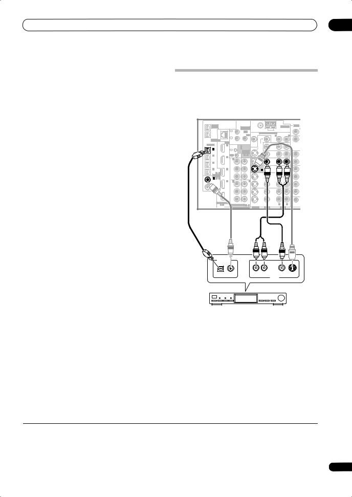
|
Connecting your equipment |
03 |
The diagram shows a basic setup of this receiver together with a Blu-ray disc player, with S-video or composite video connections. See also Using the component video jacks on page 16 if your Blu-ray disc player has component video inputs/outputs. If your Blu-ray disc player offers multi-channel analog audio outputs, see
Connecting the multichannel analog inputs on page 53.
1Connect a composite or S-video output on your Bluray disc player to the BD VIDEO or BD S-VIDEO input.
Connect using a standard video cable or an S-video cable.
2Connect an optical-type1 digital audio output on your Blu-ray disc player to the OPTICAL IN 2 (BD) input.
Connect using an optical cable.
3Connect the stereo audio outputs on your Blu-ray disc player to the BD AUDIO inputs.
Connect using a stereo RCA/phono jack cable.
•If your Blu-ray disc player has multi-channel analog outputs, you can connect these instead. See also
Connecting the multichannel analog inputs on page 53.
Connecting a satellite/cable receiver or other set-top box
Satellite and cable receivers, and terrestrial digital TV tuners are all examples of so-called ‘set-top boxes’.
|
VSX-LX70 |
||||||||||||
|
MULTI-ZONE |
ANTENNA |
AUDIO |
||||||||||
|
& SOURCE |
MULTI-ZONE |
PHONO |
||||||||||
|
/REC SEL |
||||||||||||
|
OUT1 |
& SOURCE |
FM UNBAL 75 Ω |
AM LOOP |
|||||||||
|
ZONE3 |
IN |
IR |
IN |
|||||||||
|
1 |
ZONE2 MULTI-ZONE & SOURCE |
ZONE2 |
||||||||||
|
OUT2 |
OUT |
|||||||||||
|
MAIN |
R |
L |
||||||||||
|
CD |
||||||||||||
|
IN |
||||||||||||
|
IN |
||||||||||||
|
LAN (10/100) |
2 |
OUT |
||||||||||
|
HDMI |
ZONE2 |
MONI- |
||||||||||
|
OPTICAL |
IN 1 |
IN 1 (DVD/LD) |
TOR |
MONI- |
||||||||
|
CONTROL |
OUT |
TOR |
DVD/LD |
|||||||||
|
IN 2 (BD) |
OUT |
IN |
||||||||||
|
IN 1 |
IN |
|||||||||||
|
(TV/SAT) |
ASSIGN- |
OUT |
||||||||||
|
ABLE |
BD |
|||||||||||
|
IN 2 |
IN 2 |
OUT |
1 |
2 |
IN |
CD-R/ |
||||||
|
(BD) |
||||||||||||
|
IN 1 |
OUT |
TAPE/ |
||||||||||
|
TV/SAT |
MD |
|||||||||||
|
Y |
Y |
IN 1 |
IN |
|||||||||
|
IN 3 |
IN |
|||||||||||
|
(DVR/ |
(DVD/ |
R |
||||||||||
|
VCR 1) |
LD) |
VIDEO / |
R |
|||||||||
|
IN 4 |
IN 3 |
PB |
PB |
|||||||||
|
IN 2 |
GAME 1 |
|||||||||||
|
(CD-R) |
4 |
IN |
SUBW. |
|||||||||
|
1 |
||||||||||||
|
ASSIGN- |
||||||||||||
|
ABLE |
PR |
PR |
OUT |
|||||||||
|
IN 1 |
1 |
2 |
DVR/ |
SUR- |
||||||||
|
(DVD/ |
IN 4 |
IN 2 |
IN 3 |
VCR 1 |
ROUND |
|||||||
|
LD) |
||||||||||||
|
IN 2 (CD) |
Y |
Y |
IN |
|||||||||
|
(BD) |
R |
|||||||||||
|
COAXIAL |
||||||||||||
|
OUT |
PB |
PB |
OUT |
|||||||||
|
DVR/ |
||||||||||||
|
VCR 2 |
SURROUN |
|||||||||||
|
PR |
PR |
IN |
||||||||||
|
ASSIGNABLE |
(VIDEO/GAME 1) |
1 |
||||||||||
|
R |
L |
12 V TR |
||||||||||
|
1 |
4 |
ASSIGNABLE |
1 |
3 |
(DC OUT 12V/ |
|||||||
|
DIGITAL |
COMPONENT VIDEO |
S-VIDEO |
VIDEO |
AUDIO |
TOTAL 50 mA |
|||||||
DIGITAL OUT
AV OUT
STB
1 Connect the audio/video outputs on the set-top box to the TV/SAT AUDIO and VIDEO inputs.
Connect using a stereo RCA/phono jack cable and a video or S-video2 cable.
2 Connect an optical-type3 digital audio output from
your set-top box to the OPTICAL IN 1 (TV/SAT) input.4
Use an optical cable for the connection.
 Note
Note
1If your Blu-ray disc player only has an coaxial digital output, you can connect it to one of the coaxial inputs on this receiver using an coaxial cable. When you set up the receiver you’ll need to tell the receiver which input you connected the player to (see The System Setup menu on page 37.).
2See The Input Setup menu on page 64 to assign the S-VIDEO 2 input to the TV/SAT input function if you make this connection.
3If your set-top box only has a coaxial digital output, you can connect it to one of the coaxial inputs on this receiver using a coaxial digital audio cable. When you set up the receiver you’ll need to tell the receiver which input you connected the set-top box to (see The Input Setup menu on page 64).
4If your satellite/cable receiver doesn’t have a digital audio output, you can skip this step.
15
En

03 Connecting your equipment
|
• For a second recorder, use the DVR/VCR2 outputs. |
|||||||||||
|
Connecting a DVD/HDD recorder, VCR |
3 If the device can output digital audio, connect an |
||||||||||
|
and other video sources |
optical-type1 digital audio output from the recorder to |
||||||||||
|
This receiver has two sets of audio/video inputs and |
the OPTICAL IN 3 (DVR/VCR1) input. |
||||||||||
|
outputs suitable for connecting analog or digital video |
Use an optical cable for the connection.2 |
||||||||||
|
devices, including DVD/HDD recorders and VCRs. |
|||||||||||
|
VSX-LX70 |
Using the component video jacks |
||||||||||
|
MULTI-ZONE |
& SOURCE |
FM UNBAL 75 Ω |
AM LOOP |
AUDIO |
Component video should give superior picture quality |
||||||
|
OUT1 |
|||||||||||
|
& SOURCE |
MULTI-ZONE |
ANTENNA |
PHONO |
||||||||
|
/REC SEL |
|||||||||||
|
ZONE3 |
IN |
IR |
IN |
when compared to composite or S-video. You can also |
|||||||
|
1 |
R |
L |
|||||||||
|
CD |
|||||||||||
|
OUT2 |
MAIN |
OUT |
|||||||||
|
HDMI |
IN |
MONI- |
IN |
take advantage of progressive scan video (if your source |
|||||||
|
ZONE2 |
OUT |
||||||||||
|
LAN (10/100) |
2 |
||||||||||
|
OPTICAL |
IN 1 |
CONTROL IN 1 (DVD/LD) |
TOR |
MONI- |
and TV are both compatible), which delivers a very stable, |
||||||
|
IN 1 |
OUT |
TOR |
DVD/LD |
||||||||
|
IN |
IN 2 (BD) |
OUT |
IN |
||||||||
|
(TV/SAT) |
ASSIGN- |
OUT |
flicker-free picture. See the manuals that came with your |
||||||||
|
IN 2 |
IN 2 |
OUT |
ABLE |
IN |
CD-R/ |
||||||
|
1 2 |
|||||||||||
|
BD |
|||||||||||
|
(BD) |
IN 1 |
OUT |
TAPE/ |
TV and source component to check whether they are |
|||||||
|
IN 3 |
IN |
IN |
MD |
L |
|||||||
|
R |
|||||||||||
|
Y |
Y |
1 |
TV/SAT |
IN |
|||||||
|
(DVR/ |
(DVD/ |
compatible with progressive-scan video. |
|||||||||
|
VCR 1) |
LD) |
IN 2 |
IN |
R |
L |
||||||
|
(CD-R) |
|||||||||||
|
IN 4 |
IN 3 |
PB |
PB |
VIDEO / |
F |
||||||
|
GAME 1 |
|||||||||||
|
1 |
4 |
SUBW. |
CENTER |
||||||||
|
ASSIGN- |
|||||||||||
|
ABLE |
IN 4 |
PR |
PR |
OUT |
VSX-LX70 |
||||||
|
LD) |
IN 2 |
IN 3 |
VCR 1 |
||||||||
|
IN 1 1 |
2 |
DVR/ |
SUR- |
||||||||
|
(DVD/ |
ROUND |
||||||||||
|
Y |
Y |
IN |
IN 2 (CD)
|
COAXIAL |
(BD) |
R |
L |
||||||||||||||||||
|
MULTI-ZONE |
ANTENNA |
AUDIO |
|||||||||||||||||||
|
PB |
PB |
OUT |
& SOURCE |
MULTI-ZONE |
PHONO |
||||||||||||||||
|
/REC SEL |
|||||||||||||||||||||
|
OUT |
DVR/ |
OUT1 |
& SOURCE |
FM UNBAL 75 Ω |
AM LOOP |
||||||||||||||||
|
SURROUND BACK |
ZONE3 |
IN |
IR |
IN |
|||||||||||||||||
|
VCR 2 |
1 |
ZONE2 MULTI-ZONE & SOURCE |
ZONE2 |
||||||||||||||||||
|
PR |
PR |
IN |
OUT2 |
OUT |
|||||||||||||||||
|
MAIN |
R |
L |
CD |
||||||||||||||||||
|
1 |
2 |
IN |
|||||||||||||||||||
|
ASSIGNABLE |
(VIDEO/GAME 1) |
||||||||||||||||||||
|
R |
L |
12 V TRIGGER |
LAN (10/100) |
2 |
OUT |
IN |
|||||||||||||||
|
1 |
4 |
ASSIGNABLE |
1 |
3 |
(DC OUT 12V/ |
||||||||||||||||
|
DIGITAL |
COMPONENT VIDEO |
S-VIDEO |
VIDEO |
AUDIO |
TOTAL 50 mA MAX) |
HDMI |
ZONE2 |
MONI- |
|||||||||||||
|
OPTICAL |
IN 1 |
IN 1 (DVD/LD) |
TOR |
MONI- |
|||||||||||||||||
|
CONTROL |
OUT |
TOR |
DVD/LD |
||||||||||||||||||
|
1 |
IN 2 (BD) |
OUT |
IN |
||||||||||||||||||
|
IN |
IN |
||||||||||||||||||||
|
ASSIGN- |
|||||||||||||||||||||
|
(TV/SAT) |
OUT |
||||||||||||||||||||
|
ABLE |
|||||||||||||||||||||
|
BD |
|||||||||||||||||||||
|
OUT |
1 |
2 |
|||||||||||||||||||
|
IN 2 |
IN |
||||||||||||||||||||
|
(BD) |
IN 2 |
CD-R/ |
|||||||||||||||||||
|
IN 1 |
OUT |
TAPE/ |
|||||||||||||||||||
|
TV/SAT |
MD |
||||||||||||||||||||
|
Y |
Y |
IN 1 |
IN |
||||||||||||||||||
|
IN 3 |
IN |
L |
|||||||||||||||||||
|
(DVR/ |
(DVD/ |
R |
|||||||||||||||||||
|
VCR 1) |
LD) |
VIDEO / |
R |
L |
|||||||||||||||||
|
IN 4 |
IN 3 |
PB |
PB |
F |
|||||||||||||||||
|
IN 2 |
GAME 1 |
||||||||||||||||||||
|
(CD-R) |
IN |
SUBW. |
CENTER |
||||||||||||||||||
|
1 |
4 |
||||||||||||||||||||
|
ASSIGN- |
|||||||||||||||||||||
|
ABLE |
PR |
PR |
OUT |
||||||||||||||||||
|
IN 1 |
1 |
2 |
DVR/ |
SUR- |
|||||||||||||||||
|
(DVD/ |
IN 4 |
IN 2 |
IN 3 |
VCR 1 |
ROUND |
||||||||||||||||
|
LD) |
|||||||||||||||||||||
|
Y |
Y |
IN |
|
IN 2 (CD) |
(BD) |
R |
L |
|||||||||
|
COAXIAL |
||||||||||||
|
OUT |
PB |
PB |
OUT |
|||||||||
|
DVR/ |
||||||||||||
|
SURROUND BACK |
||||||||||||
|
VCR 2 |
||||||||||||
|
PR |
PR |
IN |
||||||||||
|
OPTICAL COAXIAL |
ASSIGNABLE |
(VIDEO/GAME 1) |
1 |
2 |
||||||||
|
R |
L |
12 V TRIGGER |
||||||||||
|
R AUDIO L |
VIDEO S-VIDEO |
R AUDIO L |
VIDEO |
S-VIDEO |
TOTAL 50 mA MAX) |
|||||||
|
DIGITAL OUT |
1 4 |
ASSIGNABLE |
1 |
3 |
(DC OUT 12V/ |
|||||||
|
AV OUT |
AV IN |
DIGITAL |
COMPONENT VIDEO |
S-VIDEO |
VIDEO |
AUDIO |
||||||
|
3 |
1 |
2 |
DVR, VCR, etc.
1Connect the audio/video outputs of the video player/recorder to the DVR/VCR1 AUDIO and VIDEO inputs.
Use a stereo RCA/phono jack audio cable for the audio connection and a video or S-video cable for the video connection.
•For a second recorder, use the DVR/VCR2 IN inputs.
2If the device can record, connect the DVR/VCR1 AUDIO and VIDEO outputs to the recorder’s audio/ video inputs.
Use a stereo RCA/phono jack audio cable for the audio connection and a video or S-video cable for the video connection.
|
1 |
COMPONENT |
DVD player |
|
VIDEO |
1 Connect the component video outputs of your source to a set of ASSIGNABLE COMPONENT VIDEO inputs.
Connect using a three-way component video cable.
 Note
Note
1• In order to record, you must connect the analog audio cables (the digital connection is for playback only).
•If your video component doesn’t have a digital audio output, you can skip this step.
2If your recorder only has a coaxial digital output, you can connect it to one of the coaxial inputs on this receiver using a coaxial digital audio cable. When you set up the receiver you’ll need to tell the receiver which input you connected the recorder to (see also The Input Setup menu on page 64).
16
En
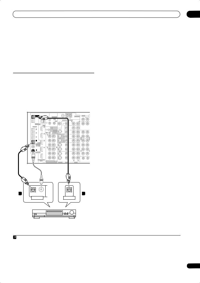
|
Connecting your equipment |
03 |
•Since they are assignable, it doesn’t matter which component video inputs you use for which source. After connecting everything, you’ll need to assign the component video inputs—see The Input Setup menu on page 64.
2 Connect the COMPONENT VIDEO OUT jacks to the component video inputs on your TV or monitor.
Use a three-way component video cable.
Connecting digital audio sources
This receiver has both digital inputs and outputs, allowing you to connect digital audio components for playback and for making digital recordings.
1Connect an optical-type1 digital audio output on your digital component to the OPTICAL IN 4 (CD-R) input.
Use an optical cable for the connection.
2For recording equipment, connect one of the optical-type DIGITAL outputs to a digital input on the recorder.
Use an optical cable to connect to the DIGITAL OUT1 or (VSX-LX70 only) OUT2 (OUT1 is shown in the
illustration).2
About the WMA9 Pro decoder
This unit has an on-board Windows Media™ Audio 9
|
Most digital components also have analog connections. |
Professional3 (WMA9 Pro) decoder, so it is possible to |
|||||||||
|
See Connecting analog audio sources on the following |
playback WMA9 Pro-encoded audio using a coaxial or |
|||||||||
|
page if you want to connect these too. |
optical digital connection when connected to a WMA9 Pro- |
|||||||||
|
VSX-LX70 |
compatible player. However, the connected PC, DVD player, |
|||||||||
|
set-top box, etc. must be able to output WMA9 Pro format |
||||||||||
|
& SOURCE |
ANTENNA |
AUDIO |
audio signals through a coaxial or optical digital output. |
|||||||
|
MULTI-ZONE |
||||||||||
|
/REC SEL |
MULTI-ZONE |
PHONO |
||||||||
|
OUT1 |
& SOURCE |
FM UNBAL 75 Ω |
AM LOOP |
|||||||
|
ZONE3 |
IN |
IR |
IN |
|||||||
|
1 |
ZONE2 MULTI-ZONE & SOURCE |
ZONE2 |
||||||||
|
OUT2 |
OUT |
|||||||||
|
MAIN |
R |
L |
||||||||
|
CD |
||||||||||
|
IN |
||||||||||
|
IN |
||||||||||
|
LAN (10/100) |
2 |
OUT |
||||||||
|
HDMI |
ZONE2 |
MONI- |
||||||||
|
OPTICAL |
IN 1 |
CONTROL IN 1 (DVD/LD) |
TOR |
MONI- |
||||||
|
OUT |
TOR |
DVD/LD |
||||||||
|
IN 2 (BD) |
OUT |
IN |
||||||||
|
IN 1 |
IN |
|||||||||
|
(TV/SAT) |
ASSIGN- |
OUT |
||||||||
|
ABLE |
BD |
|||||||||
|
IN 2 |
IN 2 |
OUT |
1 2 |
IN |
CD-R/ |
|||||
|
(BD) |
||||||||||
|
IN 1 |
OUT |
TAPE/ |
||||||||
|
TV/SAT |
MD |
|||||||||
|
Y |
Y |
IN 1 |
IN |
|||||||
|
IN 3 |
IN |
L |
||||||||
|
(DVR/ |
(DVD/ |
R |
||||||||
|
VCR 1) |
LD) |
VIDEO / |
R |
L |
||||||
|
IN 4 |
IN 3 |
PB |
PB |
|||||||
|
IN 2 |
GAME 1 |
|||||||||
|
(CD-R) |
IN |
SUBW. |
CENTE |
|||||||
|
1 |
4 |
|||||||||
|
ASSIGN- |
||||||||||
|
ABLE |
PR |
PR |
OUT |
|||||||
|
IN 1 1 |
2 |
DVR/ |
SUR- |
|||||||
|
(DVD/ |
IN 4 |
IN 2 |
IN 3 |
VCR 1 |
ROUND |
|||||
|
LD) |
||||||||||
|
IN 2 (CD) |
Y |
Y |
IN |
|||||||
|
(BD) |
R |
L |
||||||||
|
COAXIAL |
||||||||||
|
OUT |
PB |
PB |
OUT |
|||||||
|
DVR/ |
||||||||||
|
VCR 2 |
SURROUND BACK |
|||||||||
|
PR |
PR |
IN |
||||||||
|
ASSIGNABLE |
(VIDEO/GAME 1) |
1 |
2 |
|||||||
|
R |
L |
12 V TRIGGER |
||||||||
|
1 4 |
ASSIGNABLE 1 3 |
(DC OUT 12V/ |
||||||||
|
DIGITAL |
COMPONENT VIDEO |
S-VIDEO |
VIDEO |
AUDIO |
TOTAL 50 mA MAX) |
|||||
|
1 |
OPTICAL |
COAXIAL |
OPTICAL |
2 |
|
DIGITAL OUT |
DIGITAL IN |
CD-R, MD, DAT, etc.
Note
1• If your digital component only has a coaxial digital output, you can connect it to one of the coaxial inputs on this receiver using a coaxial cable. When you set up the receiver you’ll need to tell the receiver which input you connected the component to (see also The Input Setup menu on page 64).
•The digital outputs from other components can be connected to any spare digital audio inputs on this receiver. You can assign them when setting up the receiver (see also The Input Setup menu on page 64).
2• You must switch ZONE 3 ON in Using the MULTI-ZONE controls on page 58 to hear audio from the DIGITAL OUT1.
•In order to record some digital sources, you must make analog connections as explained in Connecting analog audio sources below.
3• Windows Media, and the Windows logo are trademarks, or registered trademarks of Microsoft Corporation in the United States and/or other countries.
•With WMA9 Pro, sound problems may occur depending on your computer system. Note that WMA9 Pro 96 kHz sources will be downsampled to 48 kHz.
17
En

03 Connecting your equipment
Connecting analog audio sources
This receiver features three stereo audio-only inputs. Two of these inputs have corresponding outputs for use with audio recorders.
One of the audio inputs (PHONO) is a dedicated turntable input which should not be used for any other type of component. This input also has a grounding terminal that most turntables require.
1Connect the analog audio outputs of the source component to one of the AUDIO inputs.
Connect using a stereo RCA/phono jack audio cable.
•If you’re connecting a tape deck, MD recorder, etc., connect the analog audio outputs (OUT) to the analog audio inputs on the recorder.
2Turntables only: Connect the stereo audio outputs to the PHONO inputs.
•If your turntable has a grounding wire, secure it to the ground terminal on this receiver.
|
2 |
• If your turntable has line-level outputs (i.e., it has a |
|
|
built-in phono pre-amp), connect it to the CD inputs |
||
|
instead. |
|
Turntable |
|||||||||||||||||||
|
Connecting a component to the front |
|||||||||||||||||||
|
panel inputs |
|||||||||||||||||||
|
VSX-LX70 |
The front panel inputs comprise a composite video jack |
||||||||||||||||||
|
(VIDEO), an S-video jack (S-VIDEO), stereo analog audio |
|||||||||||||||||||
|
FM UNBAL 75 Ω |
AM LOOP |
PHONO |
R |
L |
FRONT |
inputs (AUDIO L/R) and an optical digital audio input |
|||||||||||||
|
ANTENNA |
AUDIO |
PRE OUT |
|||||||||||||||||
|
R |
L |
IN |
SUBW. |
CENTER |
(DIGITAL). You can use these connections for any kind of |
||||||||||||||
|
ZONE2 MULTI-ZONE & SOURCE |
ZONE2 |
||||||||||||||||||
|
CD |
audio/video component, but they are especially |
||||||||||||||||||
|
MONI- |
OUT |
IN |
ROUND |
||||||||||||||||
|
SUR- |
|||||||||||||||||||
|
TOR |
MONI- |
ROUND |
convenient for portable equipment such as camcorders, |
||||||||||||||||
|
OUT |
TOR |
DVD/LD |
|||||||||||||||||
|
OUT |
IN |
SUR- |
|||||||||||||||||
|
OUT |
BACK |
video games and portable audio/video equipment. |
|||||||||||||||||
|
BD |
CD-R/ |
(Single) |
|||||||||||||||||
|
IN |
|||||||||||||||||||
|
TAPE/ |
R |
L |
|||||||||||||||||
|
TV/SAT |
MD |
• Push down on the lower portion of the front panel |
|||||||||||||||||
|
IN 1 |
IN |
IN |
L |
||||||||||||||||
|
R |
|||||||||||||||||||
|
VIDEO / |
R |
L |
door to access the front video connections. |
||||||||||||||||
|
IN |
A |
||||||||||||||||||
|
IN 2 |
IN |
||||||||||||||||||
|
GAME 1 |
FRONT |
FRONT |
CEN |
||||||||||||||||
|
SUBW. |
CENTER |
R |
L |
||||||||||||||||
|
OUT |
|||||||||||||||||||
|
DVR/ |
SUR- |
iPod |
|||||||||||||||||
|
VCR 1 |
ROUND |
AUDIO |
PARAMETER |
VIDEO |
MULTI – ZONE & |
||||||||||||||
|
IN |
(TUNE) |
SOURCE/REC SEL |
SIGNAL |
SB ch |
STEREO/ |
||||||||||||||
|
SPEAKERS |
TUNER EDIT |
BAND CONTROL ON/OFF |
SELECT |
PROCESSING |
F.S.SURR |
||||||||||||||
|
R |
L |
||||||||||||||||||
|
OUT |
PHONES |
VIDEO/GAME 2 INPUT |
|||||||||||||||||
|
DVR/ |
ENTER |
(ST) |
MCACC |
||||||||||||||||
|
SURROUND BACK |
(ST) |
USB |
SETUP MIC |
||||||||||||||||
|
VCR 2 |
|||||||||||||||||||
|
IN |
RS-232C |
||||||||||||||||||
|
1 |
2 |
MULTI CH IN |
|||||||||||||||||
|
R |
L |
12 V TRIGGER |
|||||||||||||||||
|
(DC OUT 12V/ |
|||||||||||||||||||
|
S-VIDEO |
VIDEO |
AUDIO |
TOTAL 50 mA MAX) |
SETUP |
(TUNE) |
RETURN |
DIGITAL IN S-VIDEO |
VIDEO |
L AUDIO R |
||||||||||
1
OUT
PLAY
IN
REC
R L
AUDIO IN/OUT
TV game, video camera, etc.
• Select these inputs using INPUT SELECT (remote) or the INPUT SELECTOR dial (front panel) to select
VIDEO/GAME 2.
Tape deck, etc.
18
En
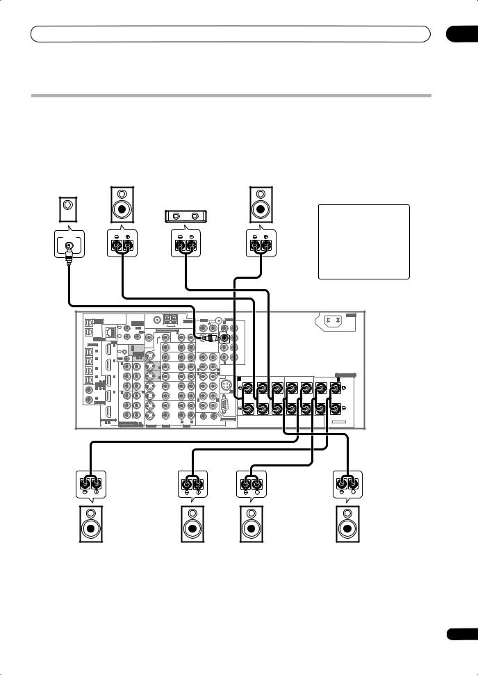
|
Connecting your equipment |
03 |
Installing your speaker system
To take full advantage of the receiver’s surround sound capabilities connect front, center, surround and surround back speakers, as well as a subwoofer. Although this is ideal, other configurations with fewer speakers—no subwoofer or no center speaker, or even no surround speakers—will work. At the very least, front left and right speakers only are necessary. Note that your main surround speakers should always be connected as a pair, but you can connect just one surround back speaker if you like (it must be connected to the left surround back terminal). You can use speakers with a nominal impedance between 6 Ωto 16 Ω(please see Switching the speaker impedance on page 71 if you plan to use speakers with an impedance of less than 8 Ω).
|
Subwoofer |
Front |
Front |
|
left |
right |
Center
LINE LEVEL
INPUT
CAUTION
These speaker terminals carry
HAZARDOUS LIVE voltage.
To prevent the risk of electric shock when connecting or disconnecting the speaker cables, disconnect the power cord before touching any uninsulated parts.
|
AC IN |
|||||||||||||||||||||||||
|
MULTI-ZONE |
ANTENNA |
AUDIO |
PRE OUT |
||||||||||||||||||||||
|
& SOURCE |
MULTI-ZONE |
PHONO |
R |
L |
|||||||||||||||||||||
|
/REC SEL |
FRONT |
||||||||||||||||||||||||
|
OUT1 |
& SOURCE |
FM UNBAL 75 Ω |
AM LOOP |
||||||||||||||||||||||
|
IN |
|||||||||||||||||||||||||
|
ZONE3 |
IR |
IN |
|||||||||||||||||||||||
|
1 |
ZONE2 MULTI-ZONE & SOURCE |
ZONE2 |
|||||||||||||||||||||||
|
OUT2 |
OUT |
||||||||||||||||||||||||
|
MAIN |
R |
L |
SUBW. |
CENTER |
|||||||||||||||||||||
|
CD |
|||||||||||||||||||||||||
|
IN |
|||||||||||||||||||||||||
|
IN |
|||||||||||||||||||||||||
|
LAN (10/100) |
2 |
OUT |
|||||||||||||||||||||||
|
HDMI |
ZONE2 |
MONI- |
SUR- |
||||||||||||||||||||||
|
ROUND |
|||||||||||||||||||||||||
|
OPTICAL |
IN 1 |
IN 1 (DVD/LD) |
TOR |
MONI- |
DVD/LD |
||||||||||||||||||||
|
CONTROL |
OUT |
TOR |
|||||||||||||||||||||||
|
IN 2 (BD) |
OUT |
IN |
SUR- |
||||||||||||||||||||||
|
IN |
1 |
IN |
|||||||||||||||||||||||
|
ASSIGN- |
OUT |
ROUND |
|||||||||||||||||||||||
|
(TV/SAT) |
BACK |
||||||||||||||||||||||||
|
ABLE |
BD |
||||||||||||||||||||||||
|
IN 2 |
OUT |
1 |
2 |
IN |
|||||||||||||||||||||
|
(BD) |
IN 2 |
CD-R/ |
R |
L |
(Single) |
||||||||||||||||||||
|
IN 1 |
OUT |
TAPE |
|||||||||||||||||||||||
|
TV/SAT |
MD |
||||||||||||||||||||||||
|
Y |
Y |
IN 1 |
IN |
||||||||||||||||||||||
|
IN 3 |
IN |
L |
|||||||||||||||||||||||
|
(DVR/ |
(DVD/ |
R |
|||||||||||||||||||||||
|
VCR 1) |
LD) |
VIDEO / |
R |
L |
SPEAKERS |
||||||||||||||||||||
|
IN 4 |
IN 3 |
PB |
PB |
FRONT |
|||||||||||||||||||||
|
IN 2 |
GAME 1 |
A |
FRONT |
CENTER |
SURROUND |
SURROUND BACK / B |
|||||||||||||||||||
|
(CD-R) |
IN |
IN |
R |
R |
L(Single) |
||||||||||||||||||||
|
1 |
4 |
SUBW. |
CENTER |
R |
L |
L |
|||||||||||||||||||
|
ASSIGN- |
|||||||||||||||||||||||||
|
ABLE |
PR |
PR |
OUT |
||||||||||||||||||||||
|
IN 1 |
1 |
2 |
DVR/ |
SUR- |
|||||||||||||||||||||
|
(DVD/ |
IN 4 |
IN 2 |
IN 3 |
VCR 1 |
ROUND |
iPod |
|||||||||||||||||||
|
LD) |
|||||||||||||||||||||||||
|
IN 2 (CD) |
Y |
Y |
IN |
||||||||||||||||||||||
|
(BD) |
R |
L |
|||||||||||||||||||||||
|
COAXIAL |
|||||||||||||||||||||||||
|
OUT |
PB |
PB |
OUT |
||||||||||||||||||||||
|
DVR/ |
|||||||||||||||||||||||||
|
SURROUND BACK |
|||||||||||||||||||||||||
|
VCR 2 |
|||||||||||||||||||||||||
|
PR |
PR |
IN |
RS-232C |
||||||||||||||||||||||
|
ASSIGNABLE |
(VIDEO/GAME 1) |
1 |
2 |
MULTI CH IN |
|||||||||||||||||||||
|
R |
L |
12 V TRIGGER |
SELECTABLE |
||||||||||||||||||||||
|
1 |
4 |
ASSIGNABLE |
1 |
3 |
(DC OUT 12V/ |
||||||||||||||||||||
|
DIGITAL |
COMPONENT VIDEO |
S-VIDEO |
VIDEO |
AUDIO |
TOTAL 50 mA MAX) |
||||||||||||||||||||
|
VSX-LX70 |
Surround left
Surround back left
Connecting the speakers
Each speaker connection on the receiver comprises a positive (+) and negative (–) terminal. Make sure to match these up with the terminals on the speakers themselves.
Surround
right
Surround back right
 Caution
•Make sure that all the bare speaker wire is twisted together and inserted fully into the speaker terminal. If any of the bare speaker wire touches the back panel it may cause the power to cut off as a safety measure.
19
En
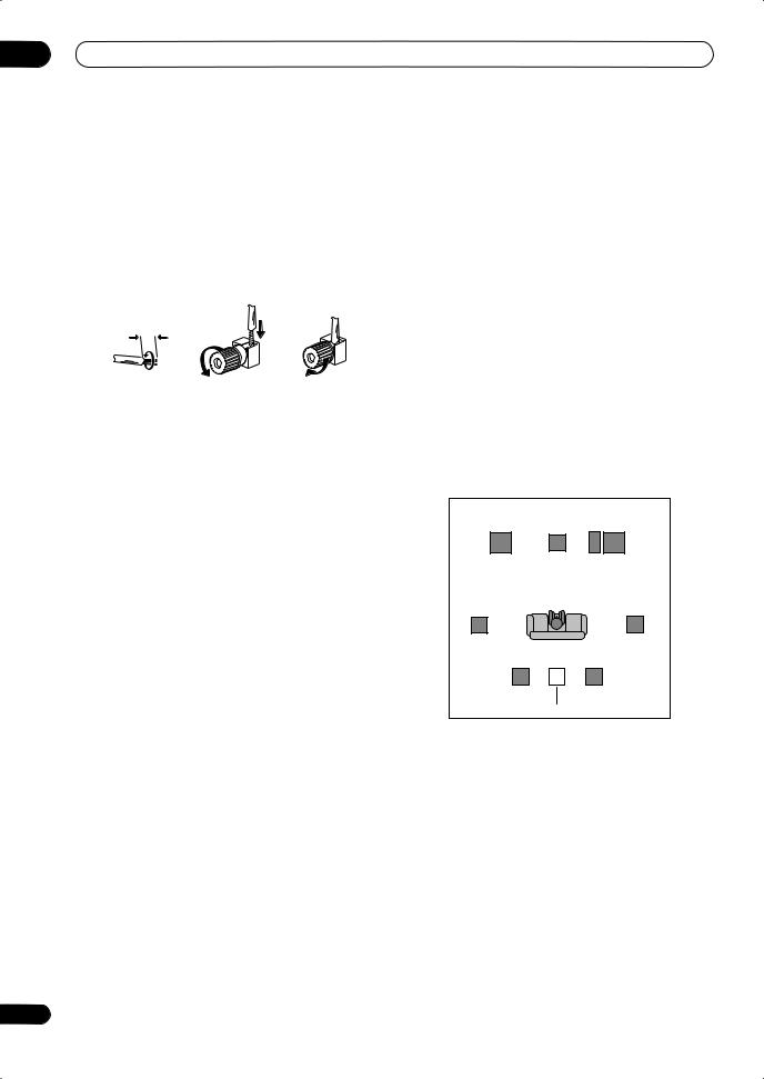
03 Connecting your equipment
Bare wire connections
Make sure that the speaker cable you’re going to use is properly prepared with about 10 mm of insulator stripped from each wire, and the exposed wire strands twisted together (fig. A).
To connect a terminal, unscrew the terminal a few turns until there is enough space to insert the exposed wire (fig. B). Once the wire is in position, tighten the terminal until the wire is firmly clamped (fig. C).
|
fig. A |
fig. B |
fig. C |
|
10 mm |
 Important
•Please refer to the manual that came with your speakers for details on how to connect the other end of the speaker cables to your speakers.
•Other connections on page 51 provides greater detail on alternate speaker setups, such as using speaker system B (page 54), bi-amping (page 55) and biwiring (page 55).
•If you are using a THX certified subwoofer use the THX INPUT jack on the subwoofer (if your subwoofer has one) or switch the filter position to THX on your subwoofer.
Placing the speakers
Where you put your speakers in the room has a big effect on the quality of the sound. The following guidelines should help you to get the best sound from your system.
•The subwoofer can be placed on the floor. Ideally, the other speakers should be at about ear-level when you’re listening to them. Putting the speakers on the floor (except the subwoofer), or mounting them very high on a wall is not recommended.
•For the best stereo effect, place the front speakers 2 m to 3 m apart, at equal distance from the TV.
•When placing speakers near the TV, we recommend using magnetically shielded speakers to prevent possible interference, such as discoloration of the picture when the TV is switched on. If you do not have magnetically shielded speakers and notice discoloration of the TV picture, move the speakers farther away from the TV.
•If you’re using a center speaker, place the front speakers at a wider angle. If not, place them at a narrower angle.
•Place the center speaker above or below the TV so that the sound of the center channel is localized at the TV screen. Also, make sure the center speaker does not cross the line formed by the leading edge of the front left and right speakers.
•It is best to angle the speakers towards the listening position. The angle depends on the size of the room. Use less of an angle for bigger rooms.
•Surround and surround back speakers should be positioned 60 cm to 90 cm higher than your ears and titled slight downward. Make sure the speakers don’t face each other. For DVD-Audio, the speakers should be more directly behind the listener than for home theater playback.
•Try not to place the surround speakers farther away from the listening position than the front and center speakers. Doing so can weaken the surround sound effect.
•To achieve the best possible surround sound, install your speakers as shown below. Be sure all speakers are installed securely to prevent accidents and improve sound quality.
|
Front |
Center |
Front |
|
left |
right |
|
|
Subwoofer |
||
|
Surround |
Surround |
|
|
left |
right |
|
|
Listening position |
||
|
Surround back left |
Surround back right |
Single surround back speaker
 Caution
•Make sure that all speakers are securely installed. This not only improves sound quality, but also reduces the risk of damage or injury resulting from speakers being knocked over or falling in the event of external shocks such as earthquakes.
20
En
![]()
Connecting your equipment
The diagrams below show suggested surround and surround back speaker orientation. The first diagram (fig. A) shows orientation with one surround back speaker (or none) connected. The second (fig. B) shows orientation with two surround back speakers connected.
|
90º to 120º |
|||
|
LS |
RS |
LS |
RS |
|
0º to 60º |
|||
|
LS |
RS |
||
|
SB |
SBL SBL SBR |
SBR |
|
|
fig. A |
fig. B |
•If you have two surround back speakers THX recommends placing them together and the same distance from your listening position (see below).
THX speaker system setup
If you have a complete THX speaker system, follow the diagram below to place your speakers. Note that the surround speakers ( indicates bi-polar radiating speakers) should output at an angle parallel to the listener.
L C R
SBL SBR
Surround back
•If you have two surround back speakers THX recommends placing them together and the same distance from your listening position for the following THX modes: THX Select2 CINEMA, THX MUSICMODE and THX GAMES MODE.
See also THX Audio Setting on page 50 to make the settings that will give you the best sound experience when using the Home THX modes (page 30).
03
Connecting antennas
The supplied antennas provide a simple way to listen to AM and FM radio. If you find that reception quality is poor, an outdoor antenna should give you better sound quality—see Connecting external antenna to improve FM reception below.
|
VSX-LX70 |
||||||||||||||||||||
|
MULTI-ZONE |
ANTENNA |
AUDIO |
PRE OUT |
|||||||||||||||||
|
& SOURCE |
MULTI-ZONE |
PHONO |
R |
L |
||||||||||||||||
|
/REC SEL |
FRONT |
|||||||||||||||||||
|
OUT1 |
& SOURCE |
FM UNBAL 75 Ω |
AM LOOP |
|||||||||||||||||
|
ZONE3 |
IN |
IR |
IN |
|||||||||||||||||
|
1 |
ZONE2 MULTI-ZONE & SOURCE |
ZONE2 |
||||||||||||||||||
|
OUT2 |
OUT |
|||||||||||||||||||
|
MAIN |
R |
L |
CD |
SUBW. |
CENTER |
|||||||||||||||
|
IN |
||||||||||||||||||||
|
OUT |
IN |
|||||||||||||||||||
|
LAN (10/100) |
2 |
|||||||||||||||||||
|
HDMI |
ZONE2 |
MONI- |
SUR- |
|||||||||||||||||
|
ROUND |
||||||||||||||||||||
|
OPTICAL |
IN 1 |
IN 1 (DVD/LD) |
TOR |
MONI- |
||||||||||||||||
|
CONTROL |
OUT |
TOR |
DVD/LD |
|||||||||||||||||
|
IN 2 (BD) |
OUT |
IN |
SUR- |
|||||||||||||||||
|
IN |
1 |
IN |
||||||||||||||||||
|
(TV/SAT) |
ASSIGN- |
OUT |
BACK |
|||||||||||||||||
|
ABLE |
BD |
|||||||||||||||||||
|
IN 2 |
IN 2 |
OUT |
1 |
2 |
IN |
CD-R/ |
(Single) |
|||||||||||||
|
(BD) |
R |
L |
||||||||||||||||||
|
IN 1 |
OUT |
TAPE |
||||||||||||||||||
|
TV/SAT |
MD |
|||||||||||||||||||
|
Y |
Y |
IN 1 |
IN |
|||||||||||||||||
|
IN 3 |
IN |
L |
||||||||||||||||||
|
(DVR/ |
(DVD/ |
R |
||||||||||||||||||
|
VCR 1) |
LD) |
VIDEO / |
R |
L |
||||||||||||||||
|
IN 4 |
IN 3 |
PB |
PB |
FRONT |
||||||||||||||||
|
IN 2 |
GAME 1 |
A |
FRONT |
CEN |
||||||||||||||||
|
(CD-R) |
IN |
IN |
||||||||||||||||||
|
1 |
4 |
SUBW. |
CENTER |
R |
L |
|||||||||||||||
|
ASSIGN- |
||||||||||||||||||||
|
ABLE |
PR |
PR |
OUT |
|||||||||||||||||
|
IN 1 |
1 |
2 |
DVR/ |
SUR- |
||||||||||||||||
|
(DVD/ |
IN 4 |
IN 2 |
IN 3 |
VCR 1 |
ROUND |
iPod |
||||||||||||||
|
LD) |
||||||||||||||||||||
|
IN 2 (CD) |
Y |
Y |
IN |
|||||||||||||||||
|
(BD) |
R |
L |
||||||||||||||||||
|
COAXIAL |
||||||||||||||||||||
|
OUT |
PB |
PB |
OUT |
|||||||||||||||||
|
DVR/ |
||||||||||||||||||||
|
SURROUND BACK |
||||||||||||||||||||
|
VCR 2 |
||||||||||||||||||||
|
PR |
PR |
IN |
RS-232C |
|||||||||||||||||
|
ASSIGNABLE |
(VIDEO/GAME 1) |
1 |
2 |
MULTI CH IN |
||||||||||||||||
|
R |
L |
12 V TRIGGER |
||||||||||||||||||
|
1 |
4 |
ASSIGNABLE |
1 |
3 |
(DC OUT 12V/ |
|||||||||||||||
|
DIGITAL |
COMPONENT VIDEO |
S-VIDEO |
VIDEO |
AUDIO |
TOTAL 50 mA MAX) |
|||||||||||||||
AM loop antenna
1 Assemble the stand as shown in the illustration.1
•Bend the stand in the direction indicated (fig. A).
•Clip the loop into the stand (fig. B).
•It’s possible to fix the AM antenna to a wall (fig. C). Before fixing, make sure that the reception is satisfactory.
2Pull off the protective shields of both AM antenna wires.
3Press the AM LOOP antenna terminal tabs to open and insert one wire into each terminal.
4Release the tabs to secure the AM antenna wires.
5Place the AM antenna on a flat surface and point in the direction giving the best reception.
Avoid placing near computers, television sets or other electrical appliances and do not let it come into contact with metal objects.
 Note
Note
1 Do not use any antennas other than the supplied AM loop antenna.
21
En
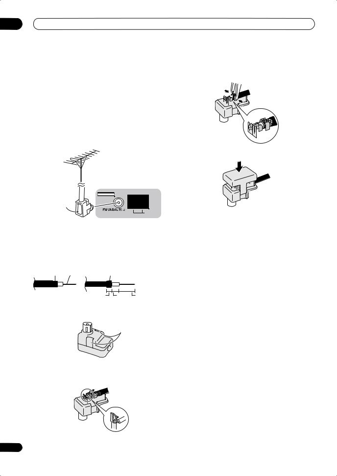
03 Connecting your equipment
FM wire antenna
• Connect the FM wire antenna to the FM UNBAL 75 Ω in the same way as the AM antenna.
For best results, extend the FM antenna fully and fix to a wall or door frame. Don’t drape loosely or leave coiled up.
Connecting external antenna to improve FM reception
Use an F connector to connect an external FM antenna using a coaxial 75 Ω cable.
|
ANTENNA |
|
|
Antenna |
|
|
adapter |
AM LOOP |
Using the antenna adapter
Use the antenna adaptor to terminate the coaxial cable used with an external FM antenna.
1 Cut and strip the coaxial cable to the specification shown in the diagram.
2 Open the adaptor body by pulling apart the tabs on either side.
Tabs
3 Insert the cable as shown, then use a pair of pliers to wrap the end of the wire around the binding post. Snip off the excess wire.
4 Use pliers to secure the cable by pinching the clamps together, as shown.
5 Push the body cover back on.
22
En
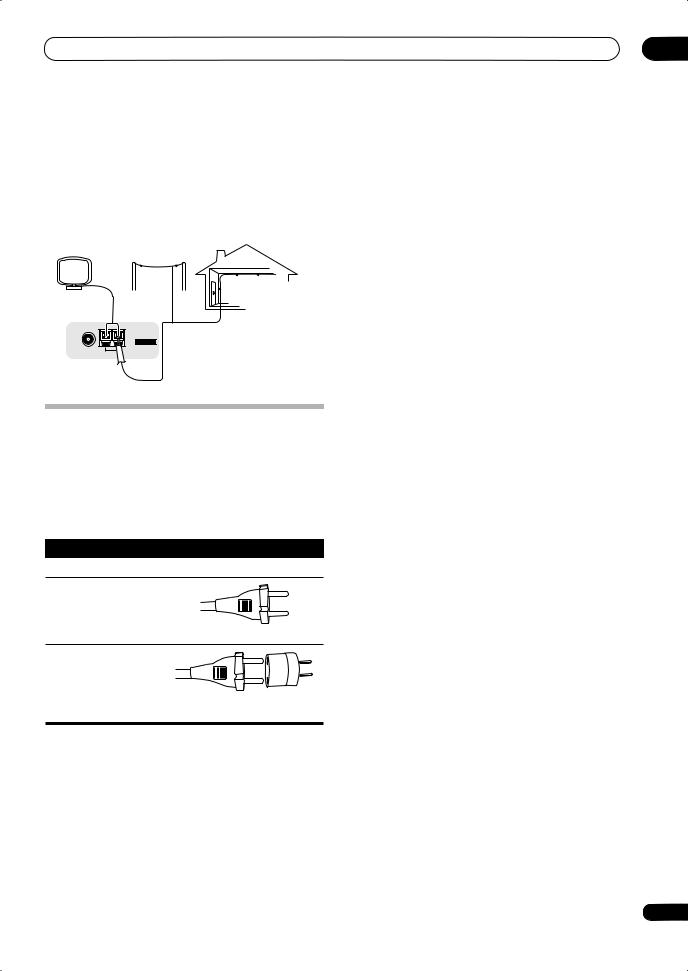
|
Connecting your equipment |
03 |
Using an external antenna to improve AM reception
To improve AM reception, connect a 5 m to 6 m length of vinyl-coated wire to the AM LOOP terminals without disconnecting the supplied AM loop antenna.
For the best possible reception, suspend horizontally outdoors.
Outdoor antenna
Indoor antenna (vinyl-coated wire)
5 m to 6 m
ANTENNA
Plugging in the receiver
After you’ve finished making all connections, plug the receiver into an AC outlet.
The type of cord and the plug converter which can be used depends on the power voltage in each region or country. Please make sure you use the correct cord and plug converter due to the possibility of fire or other hazard if used incorrectly (see below).
AC power cord and converter plug use
|
Region |
Plug type |
|
For European type region |
|
|
Caution |
|
|
Do not use this power cord |
|
|
set in Singapore and |
|
|
Malaysia. |
European two-pin plug |
|
For regions with two pin flat- |
|
|
bladed plug |
European two-pin plug with two-pin flat-bladed converter plug
 Caution
•Handle the power cord by the plug part. Do not pull out the plug by tugging the cord, and never touch the power cord when your hands are wet, as this could cause a short circuit or electric shock. Do not place the unit, a piece of furniture, or other object on the power cord or pinch the cord in any other way. Never make a knot in the cord or tie it with other cables. The power cords should be routed so that they are not likely to be stepped on. A damaged power cord can cause a fire or give you an electric shock. Check the power cord once in a while. If you find it damaged, ask your nearest Pioneer authorized independent service company for a replacement.
•Do not use any power cord other than the one supplied with this unit.
•Do not use the supplied power cord for any purpose other than that described below.
•The receiver should be disconnected by removing the mains plug from the wall socket when not in regular use, e.g., when on vacation.
•Make sure the blue STANDBY/ON light has gone out before unplugging.
1Plug the supplied power cord into the AC IN socket on the back of the receiver.
2Plug the other end into a power outlet.
23
En
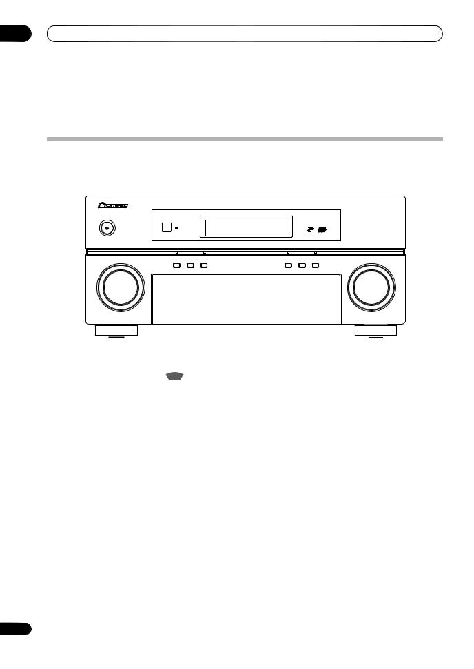
04 Controls and displays
Chapter 4:
Controls and displays
Front panel
Illustration shows the VSX-LX70 front panel
|
1 |
2 |
3 |
4 |
5 |
6 |
7 |
8 |
|||
|
VSX-LX70 |
||||||||||
|
STANDBY/ON |
||||||||||
|
PHASE |
ADVANCED |
DIGITAL PRECISION |
DIGITAL VIDEO |
|||||||
|
CONTROL |
MCACC |
PROCESSING |
SCALER |
HDMI |
||||||
|
PHASE |
MCACC |
AUTO SURR/ |
HOME |
STANDARD |
ADVANCED |
|||||
|
CONTROL |
POSITION |
STREAM DIRECT |
THX |
SURROUND |
SURROUND |
|||||
|
INPUT |
MASTER |
|||||||||
|
SELECTOR |
VOLUME |
|
9 |
10 |
11 |
12 |
13 |
14 |
15 |
16 |
17 |
18 |
||
|
AUDIO |
PARAMETER |
VIDEO |
MULTI – ZONE & |
SIGNAL |
SB ch |
STEREO/ |
|||||
|
SPEAKERS |
(TUNE) |
TUNER EDIT BAND |
SOURCE/REC SEL |
||||||||
|
CONTROL ON/OFF |
SELECT PROCESSING |
F.S.SURR |
|||||||||
|
PHONES |
MCACC |
VIDEO/GAME 2 INPUT |
|||||||||
|
(ST) |
ENTER |
(ST) |
USB |
||||||||
|
SETUP MIC |
|||||||||||
|
SETUP |
(TUNE) |
RETURN |
DIGITAL IN S-VIDEO |
VIDEO |
L AUDIO |
R |
|||||
|
19 |
20 |
21 |
22 |
23 |
24 |
25 |
1INPUT SELECTOR dial
Use to select an input source.
2STANDBY/ON
Switches the receiver between on and standby. Power indicator lights when the receiver is on.
3PHASE CONTROL – Press to switch on/off Phase Control or Full Band Phase Control (page 10).
MCACC POSITION – Press to switch between MCACC presets (page 32).
AUTO SURR/STREAM DIRECT – Press to select Auto Surround (page 29) or Stream Direct (page 31) listening.
4 Remote sensor
Receives the signals from the remote control (see
Operating range of remote control unit on page 25).
5Character display
See Display on page 26.
6PHASE CONTROL indicator – Lights to indicate Phase Control or Full Band Phase Control is selected (page 10).
ADVANCED MCACC indicator – Lights when one of the MCACC presets (page 32) is selected.1
Digital Precision Processing indicator – Lights to indicate digital processing (for example, it disappears when Pure Direct (page 31) is on, or when listening through the multichannel analog inputs).
 Note
Note
1 The MCACC indicator does not light when the MCACC preset memory currently being selected has not been corrected with Acoustic Calibration EQ Professional or when EQ is set to OFF in the Audio parameter menu (see Setting the Audio options on page 68).
24
En
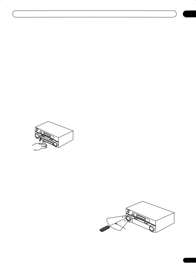
DIGITAL VIDEO SCALER indicator – Lights when Resolution is set to a setting other than PURE (for example, when the video input signal is upscaled) (page 68).
HDMI indicator – Blinks when connecting an HDMIequipped component; lights when the component is connected (page 52).
7Listening mode buttons
HOME THX – Press to select a Home THX listening mode (page 30).
STANDARD SURROUND – Press for Standard decoding and to switch between the various 2 Pro Logic IIx and Neo:6 options (page 29).
ADVANCED SURROUND – Use to switch between the various surround modes (page 30).
8MASTER VOLUME dial
9Front panel controls
To access the front panel controls, push gently on the lower third portion of the panel with your finger.
10 SPEAKERS
Use to change the speaker system (page 54).
11 AUDIO PARAMETER
Use to access the Audio options (page 68).
12 VIDEO PARAMETER
Use to access the Video options (page 69).
13 TUNER EDIT
Use with /to memorize and name stations for recall (page 36).
14 BAND
Switches between AM and FM radio bands (page 35).
15 MULTI-ZONE & SOURCE/REC SEL controls
If you’ve made MULTI-ZONE connections (see MULTIZONE listening on page 56) use these controls to control the sub zone from the main zone (see Using the MULTIZONE controls on page 58).
You will also need to use the REC SEL controls when recording a source (see Making an audio or a video recording on page 70).
16 SIGNAL SELECT
Use to select an input signal (page 32).
17 SBch PROCESSING
Selects the surround back channel mode (page 32) or virtual surround back mode (page 33).
18 STEREO/F.S.SURR
Switches between the stereo playback mode (page 31) and the Front Stage Surround Advance mode (page 31).
19 PHONES jack
Use to connect headphones. When the headphones are connected, there is no sound output from the speakers.
20 SETUP
Press to access the System Setup menu (see page 37).
21 / / / (TUNE/ST) /ENTER
Use the arrow buttons when setting up your surround sound system (see page 37). Use the TUNE /buttons to find radio frequencies and use ST / to find preset stations (page 36).
22 RETURN
Press to confirm and exit the current menu screen.
23USB interface (VSX-LX70 only) Connect a USB audio device for playback.
See the separate manual for HOME MEDIA GALLERY.
24MCACC SETUP MIC jack
Use to connect the supplied microphone.
25 VIDEO/GAME 2 INPUT
See Connecting a component to the front panel inputs on page 18.
Operating range of remote control unit
The remote control may not work properly if:
•There are obstacles between the remote control and the receiver’s remote sensor.
•Direct sunlight or fluorescent light is shining onto the remote sensor.
•The receiver is located near a device that is emitting infrared rays.
•The receiver is operated simultaneously with another infrared remote control unit.
30
30
7 m
25
En
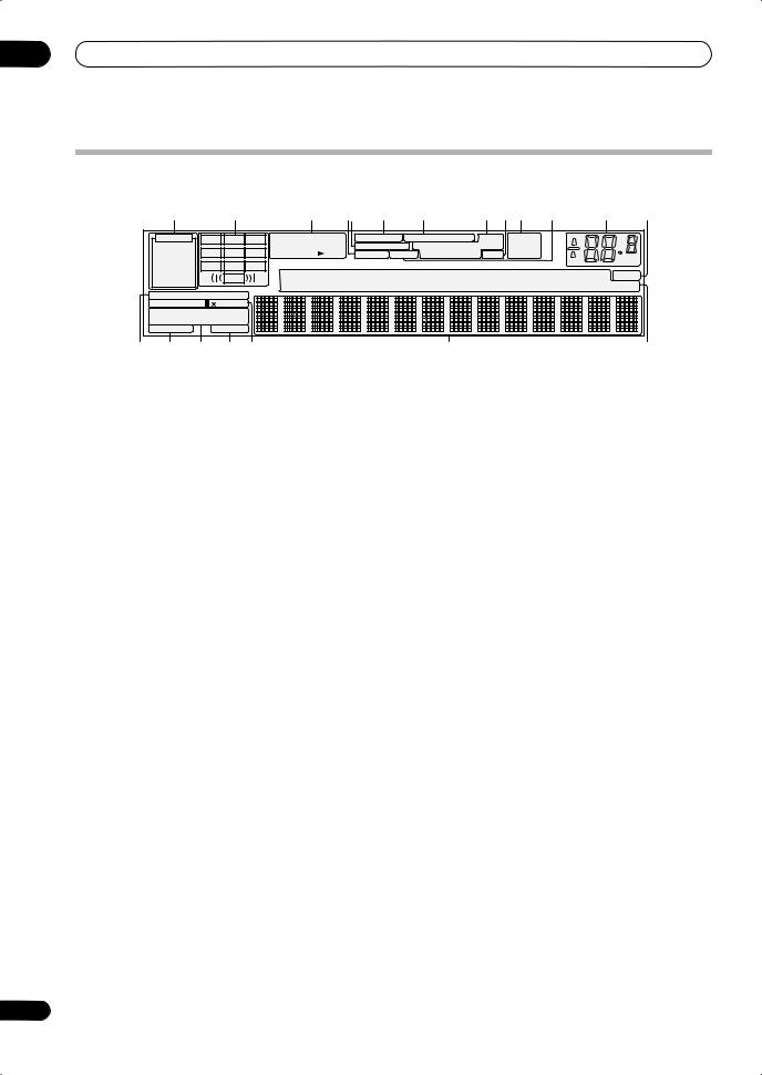
04 Controls and displays
Display
Illustration shows the VSX-LX70 display
|
1 |
2 |
3 |
4 5 |
6 |
7 |
8 |
9 |
10 |
11 |
12 |
13 |
|
AUTO |
L |
C |
R |
|
|
PCM |
SL |
S |
SR |
|
|
HDMI |
||||
|
SBL |
SB |
SBR |
||
|
DIGITAL |
LFE |
|||
|
ANALOG |
||||
STREAM DIRECT
2PRO LOGIC Neo :6
THX ADV.SURROUND
STEREO STANDARD SP  AB SLEEP
14 15 16 17 18
|
2DIGITAL 2HD |
FULL BAND PHASE CONTROL |
DNR |
TUNED |
||||
|
DTS WMA9 Pro |
MULTI-ZONE |
DIALOG E |
ATT OVER |
STEREO |
|||
|
AAC DSD |
PCM |
S.RTRV SOUND Hi-Bit/Sampling V.SB |
MONO |
dB |
|||
|
CD |
TUNER |
DVD |
TV |
VIDEO |
HMG |
SR+ |
|
|
CD-R |
PHONO iPod |
BDP |
DVR |
HDMI |
[ 1 ] [ 2 ] |
[ 3 ] [ 4 ] |
19 20
1 SIGNAL indicators
Light to indicate the currently selected input signal. AUTO lights when the receiver is set to select the input signal automatically (page 32).
2 Program format indicators
These change according to which channels are active in digital sources.
L – Left front channel C – Center channel
R – Right front channel
SL – Left surround channel
S – Surround channel (mono) SR – Right surround channel
SBL – Left surround back channel SB – Surround back channel (mono) SBR – Right surround back channel
LFE – Low frequency effects channel (the ((( ))) indicators light when an LFE signal is being input)
3 Digital format indicators
Light when a signal encoded in the corresponding format is detected (DSD PCM lights during DSD (Digital Stream Direct) to PCM conversion with SACDs).
4 S.RTRV
Lights when the Sound Retriever is switched on (page 68).
5 MULTI-ZONE
Lights when the MULTI-ZONE feature is active (page 56).
6 FULL BAND
Lights when the Full Band Phase Control is switched on (page 10).
7 PHASE CONTROL
Lights when the Phase Control or Full Band Phase Control is switched on (page 10).
8 Sound processing indicators
Light according to the active Audio parameter(s) (page 68) and/or ANALOG ATT (page 71).
9 V.SB
Lights during Virtual surround back processing (page 33).
10TUNER indicators
TUNED – Lights when a broadcast is being received.
26
STEREO – Lights when a stereo FM broadcast is being received in auto stereo mode.
MONO – Lights when the mono mode is set using the MPX button.
11 SOUND
Lights when any of the Midnight, Loudness or tone controls feature is selected (page 68).
12 Master volume level
Shows the overall volume level. –80dB indicates the minimum level, and +12dB indicates the maximum level.
13 SR+
Lights when the SR+ mode is switched on (page 60).
14 STREAM DIRECT
Lights when Direct/Pure Direct is selected (page 31).
15 Speaker indicators
Lights to indicate the current speaker system, A and/or B (page 54).
16Listening mode indicators
THX – Lights when one of the Home THX modes is selected.
ADV.SURROUND – Lights when one of the Advanced Surround modes has been selected.
STEREO – Lights when stereo listening is switched on (see Listening in stereo on page 31).
STANDARD – Lights when one of the Standard Surround modes is switched on (see Listening in surround sound on page 29).
17SLEEP
Lights when the receiver is in sleep mode (page 71).
18Matrix decoding format indicators
2 PRO LOGIC IIx – This lights to indicate
2 Pro Logic II / 2 Pro Logic IIx decoding (page 29).
Neo:6 – When one of the Neo:6 modes of the receiver is on, this lights to indicate Neo:6 processing (page 29).
19Character display
Displays various system information.
20 Input source indicators
Light to indicate the input source you have selected.
En
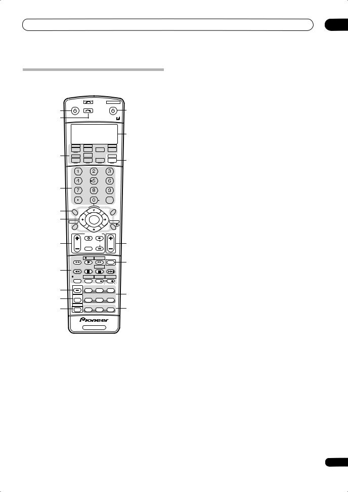
Controls and displays
Remote control
Illustration shows the VSX-LX70 remote control
|
INPUT |
SYSTEM OFF |
|||||
|
RECEIVER |
SOURCE |
|||||
|
1 |
SELECT |
12 |
||||
|
2 |
||||||
|
13 |
||||||
|
CD |
CD-R |
HDMI |
||||
|
3 |
DVD |
TV |
BD |
TVCTRL |
||
|
DVR2 |
HOME MEDIA |
ZONE2/3 |
||||
|
GALLERY |
14 |
|||||
|
DVR1 |
iPod |
TUNER |
RECEIVER |
|||
|
SLEEP |
DIMMER |
ANALOG |
||||
|
ATT |
||||||
|
SR+ |
GENRE |
|||||
|
4 |
||||||
|
D.ACCESS |
CLASS |
|||||
|
CLEAR |
DISC |
|||||
|
+10 |
CH |
ENTER |
||||
|
LEVEL |
||||||
|
A PARAMETER |
V PARAMETER |
|||||
|
5 |
TOP MENU |
MENU T.EDIT |
||||
|
TUNE |
||||||
|
6 |
BAND |
ST |
ST |
|||
|
ENTER |
||||||
|
SETUP |
RETURN |
|||||
|
TUNE |
||||||
|
PROGRAM |
||||||
|
TV CONTROL |
||||||
|
7 |
SELECT |
15 |
||||
|
TVVOL |
INPUT |
TV CH |
VOL |
|||
|
TV/DTV |
REC |
INFO |
16 |
|||
|
MUTE |
||||||
|
8 |
MPX |
REC STOP |
JUKEBOX |
|||
|
AUDIO |
SUBTITLE |
HDD |
DVD |
|||
|
DISP |
CH |
CH |
||||
|
PHOTO T.DISP |
STEREO/ |
|||||
|
9 |
STATUS |
SIGNAL SEL |
SBch |
F.S.SURR |
||
|
17 |
||||||
|
10 |
MULTI OPE |
THX |
STANDARD |
ADV.SURR |
||
|
11 |
SHIFT |
PHASE |
MCACC |
S.DIRECT |
18 |
RECEIVER
The remote has been conveniently color-coded according to component control using the following system (press the corresponding input source button to access):
•Green – Receiver controls (see below)
•Red – DVD controls (page 78)
•Blue – Tuner controls (page 35)
•Yellow – iPod controls (page 51)
•White – Other controls (page 78)
1 RECEIVER
This switches between standby and on for this receiver.
2 INPUT SELECT
Use to select the input source (use SHIFT for INPUT SELECT  ).
).
04
3 Input source buttons
Press to select control of other components (see
Controlling the rest of your system on page 74).
4 Number buttons and other receiver/component controls
Use the number buttons to directly select a radio frequency (page 35) or the tracks on a CD, DVD, etc.
DISC (ENTER) can be used to enter commands for TV or DTV, and also to select a disc in a multi-CD player.
Press RECEIVER first to access:
SLEEP – Use to put the receiver in sleep mode and select the amount of time before sleep (page 71).
DIMMER – Dims or brightens the display (page 71).
ANALOG ATT – Attenuates (lowers) the level of an analog input signal to prevent distortion (page 71).
SR+ – Switches the SR+ mode on/off (page 60).
GENRE – Automatically selects the most appropriate Advanced Surround mode for the genre of the source currently being played back (this feature is available only when a Pioneer DVD recorder supporting HDMI Control is connected to this receiver via HDMI)
(page 34).
CH LEVEL – Press repeatedly to select a channel, then use / to adjust the level (page 49).
Press TUNER first to access:
D.ACCESS – After pressing, you can access a radio station directly using the number buttons (page 35).
CLASS – Switches between the three banks (classes) of radio station presets (page 36).
5 Tuner/component control buttons/SETUP
These button controls can be accessed after you have selected the corresponding input source button (DVD, DVR1, TV, etc.). The BAND and T.EDIT tuner controls are explained from page 35. Press RECEIVER first to access the following controls:
A PARAMETER – Use to access the Audio options (page 68).
V PARAMETER – Use to access the Video options (page 69).
SETUP – Use to access the System Setup menu (page 37).
RETURN – Press to confirm and exit the current menu screen (also use to return to the previous menu with DVDs or to select closed captioning with DTV).
6 / / / (TUNE/ST) /ENTER
Use the arrow buttons when setting up your surround sound system (see page 37) and the Audio or Video options (page 68 or 69). Also used to control DVD menus/ options and for deck 1 of a double cassette deck player. Use the TUNE /buttons to find radio frequencies and use ST / to find preset stations (page 36).
27
En

04 Controls and displays
7 TV CONTROL buttons
These buttons are dedicated to control the TV assigned to the TV CTRL button. Thus if you only have one TV to hook up to this system assign it to the TV CTRL input source button. If you have two TVs, assign the main TV to the TV CTRL button (see page 74 for more on this).
TV – Use to turn on/off the power of the TV.
TV VOL +/– – Use to adjust the volume on your TV.
INPUT SELECT – Use to select the TV input signal.
TV CH +/– – Use to select channels.
8 Component control buttons
The main buttons ( , , etc.) are used to control a component after you have selected it using the input source buttons.
The controls above these buttons can be accessed after you have selected the corresponding input source button (for example DVD, DVR1 or TV). The following controls can be accessed when listening to the built-in tuner:
MPX – Switches between stereo and mono reception of FM broadcasts. If the signal is weak then switching to mono will improve the sound quality (page 35).
DISP – Switches between named station presets and radio frequencies (page 36).
9 STATUS
Press to check selected receiver settings (page 72).
10 MULTI OPE
Use this button to perform multi operations (page 76).
11 SHIFT
Press to access the controls outlined in white boxes (for
|
example, INPUT SELECT |
), or to display the currently |
selected input source in the remote control LCD.
12 SOURCE
Press to turn on/off other components connected to the receiver (see page 74 for more on this).
13 Character display (LCD)
This display shows information when transmitting control signals.
The following commands are shown when you’re setting the remote to control other components (see Controlling the rest of your system on page 74):
SETUP – Indicates the setup mode, from which you choose the options below.
PRESET – See Selecting preset codes directly on page 74.
LEARNING – See Programming signals from other remote controls on page 74.
MULTI OP – See Multi Operation and System Off on page 76.
SYS OFF – See Multi Operation and System Off on page 76.
28
DIRECT F – See Direct function on page 76.
RENAME – See Renaming input source names on page 76.
ERASE – See Erasing one of the remote control button settings on page 75.
RESET – See Resetting the remote control presets on page 75.
READ ID – See Confirming preset codes on page 75.
14 RECEIVER
Switches the remote to control the receiver (used to select the green commands above the number buttons (ANALOG ATT, etc.)). Also use this button to set up surround sound (page 8, page 37). With SHIFT, this selects the MULTI-ZONE control (page 56), shown in the display as RCV/Z2, RCV/Z3.
15 VOL +/–
Use to set the listening volume.
16 MUTE
Mutes the sound or restores the sound if it has been muted (adjusting the volume also restores the sound).
17Receiver controls
SIGNAL SEL – Use to select an input signal (page 32).
SBch – Use to select the surround/virtual back channel mode (page 32).
STEREO/F.S.SURR – Switches between the stereo playback mode (page 31) and the Front Stage Surround Advance mode (page 31).
THX – Press to select a Home THX listening mode (page 30).
STANDARD – Press for Standard decoding and to switch between the various 2 Pro Logic IIx and Neo:6 options (page 29).
ADV.SURR – Use to switch between the various surround modes (page 30).
18PHASE – Press to switch on/off Phase Control or Full Band Phase Control (page 10).
MCACC – Press to switch between MCACC presets (page 32).
S.DIRECT – Press to select Auto Surround (page 29) or Stream Direct (page 31) listening.
En
|
Listening to your system |
05 |
Chapter 5:
Listening to your system
 Important
•The listening modes and many features described in this section may not be available depending on the current source, settings and status of the receiver.
See Listening modes with different input signal formats on page 89 for more on this.
Standard surround sound
The following modes provide basic surround sound for stereo and multichannel sources.4
|
STATUS |
SIGNAL SEL |
SBch |
STEREO/ |
|
F.S.SURR |
|||
|
MULTI OPE |
THX |
STANDARD |
ADV. SURR |
|
SHIFT |
PHASE |
MCACC |
S.DIRECT |
There are many ways to listen back to sources using this receiver, but for the simplest, most direct listening option is the Auto Surround feature. The receiver automatically detects what kind of source you’re playing and selects
multichannel or stereo playback as necessary.1
|
. |
STEREO/ |
||
|
STATUS |
SIGNAL SEL |
SBch |
F.S.SURR |
|
MULTI OPE |
THX |
STANDARD |
ADV. SURR |
|
SHIFT |
PHASE |
MCACC |
S.DIRECT |
RECEIVER
•While listening to a source, press S.DIRECT (AUTO
SURR/STREAM DIRECT)2 for auto playback of a source. AUTO SURROUND shows briefly in the display before showing the decoding or playback format. Check the digital format indicators in the front panel display to see
how the source is being processed.3
•VSX-LX70 only – When listening to the FM Radio, the Neural THX feature is selected automatically (see Using Neural THX on page 35 for more on this).
Listening in surround sound
Using this receiver, you can listen to any source in surround sound. However, the options available will depend on your speaker setup and the type of source you’re listening to.
If you connected surround back speakers, see also Using surround back channel processing on page 32.
• While listening to a source, press STANDARD (STANDARD SURROUND).
If necessary, press repeatedly to select a listening mode.
•If the source is Dolby Digital, DTS, or Dolby Surround encoded, the proper decoding format will automatically be selected and shows in the display.5
With two channel sources, you can select from:
•2 Pro Logic IIx MOVIE – Up to 7.1 channel sound, especially suited to movie sources
•2 Pro Logic IIx MUSIC – Up to 7.1 channel sound, especially suited to music sources6
•2 Pro Logic IIx GAME– Up to 7.1 channel sound, especially suited to video games
•2PRO LOGIC – 4.1 channel surround sound (sound from the surround speakers is mono)
•Neo:6 CINEMA – 6.1 channel sound, especially suited to movie sources
•Neo:6 MUSIC – 6.1 channel sound, especially suited to music sources7
•Neural THX – Up to 7.1 channel sound, especially suited to music sources8
With multichannel sources, if you have connected surround back speaker(s) and have selected SBch ON, you can select (according to format):
•2 Pro Logic IIx MOVIE – See above (only available when you’re using two surround back speakers)
•2 Pro Logic IIx MUSIC – See above
 Note
Note
1• Stereo surround (matrix) formats are decoded accordingly using Neo:6 CINEMA or 2 Pro Logic IIx MOVIE (see Listening in surround sound below for more on these decoding formats).
• The Auto Surround feature is canceled if you connect headphones or select the multichannel analog inputs.
2For more options using this button, see Using Stream Direct on page 31.
3VSX-LX70 only – Neural THX is selected when Neural Radio is accessed with the HOME MEDIA GALLERY input. However, Stereo is selected when a category other than Neural Radio is accessed.
4In modes that give 6.1 channel sound, the same signal is heard from both surround back speakers.
5If surround back channel processing (page 32) is switched OFF, or the surround back speakers are set to NO (this happens automatically if the Surround back speaker setting on page 40 is set to anything but Normal (default)), 2 Pro Logic IIx becomes 2 Pro Logic II (5.1 channel sound).
6When listening to 2-channel sources in Dolby Pro Logic IIx Music mode, there are three further parameters you can adjust: Center Width, Dimension, and Panorama. See Setting the Audio options on page 68 to adjust them.
7When listening to 2-channel sources in Neo:6 Music mode, you can also adjust the center image effect (see Setting the Audio options on page 68).
8VSX-LX70 only – Neural THX can be selected with the FM input. Also, Neural THX can be selected with the HOME MEDIA GALLERY input.
29
En
 Loading…