инструкцияPioneer VSX-527

VSX-827-K/-S
VSX-527-K/-S
VSX-422-K/-S
AV Receiver
Amplificateur AV
AV Receiver
Sintoamplificatore AV
AV Receiver
Receptor AV
AV-ресивер
Quick Start Guide
Guide rapide
Kurzanleitung
Guida di avvio rapido
Snelstartgids
Guía de inicio rápido
Краткое руководство пользователя
What’s in the box
Contenu du carton d’emballage
Lieferumfang
Contenuto della confezione
Inhoud van de doos
Contenido de la caja
Комплект поставки
Thank you for buying this Pioneer product. This Quick Start Guide includes instructions for basic connections and operations to allow simple use of the receiver. For detailed descriptions of the receiver, see the “Operating Instructions” provided on the included CD-ROM ( ).Merci pour l’achat de ce produit Pioneer. Ce guide rapide contient les instructions relatives aux raccordements et opérations de base permettant une utilisation simple de ce récepteur. Pour des descriptions plus détaillées du récepteur, référez-vous au “Mode d’emploi” sur le CD-ROM ( ) fourni.Vielen Dank, dass Sie sich für dieses Pioneer-Produkt entschieden haben. Die Kurzanleitung enthält Anweisungen für grundlegende Verbindungen und Bedienvorgänge, um eine einfache Bedienung des Receivers zu ermöglichen. Detaillierte Beschreibungen des Receivers finden Sie in der „Bedienungsanleitung“ auf der mitgelieferten CD-ROM ( ).Vi ringraziamo per avere acquistato questo prodotto Pioneer. Questa Guida di avvio rapido comprende istruzioni per i collegamenti fondamentali e per le operazioni essenziali di questo ricevitore. Per una descrizione dettagliata del ricevitore, vedere le “Istruzioni per l’uso” contenute nel CD-ROM ( ) accluso.Hartelijk dank voor de aanschaf van dit Pioneer product. In deze snelstartgids vindt u de instructies voor de basisaansluitingen en de basisbediening voor een eenvoudig gebruik van de receiver. Voor meer gedetailleerde informatie wordt u verwezen naar de “Handleiding” die op de bijgeleverde CD-ROM ( ) staat.Muchas gracias por haber adquirido este producto de Pioneer. Esta Guía de inicio rápido incluye instrucciones para hacer las conexiones y operaciones básicas que le permitirán hacer un uso sencillo del receptor. Para conocer una descripción detallada del receptor, consulte el “Manual de instrucciones” suministrado con el CD-ROM ( ) incluido.Благодарим вас за приобретение данного изделия Pioneer. В данном Кратком руководстве пользователя содержатся инструкции по основным подключениям и операциям для упрощенного использования ресивера. Подробное описание ресивера см. в «Инструкции по эксплуатации», содержащихся на поставляемом CD-ROM ( ).Remote ControlTélécommandeFernbedienungTelecomandoAfstandsbedieningMando a distanciaПульт дистанционного управленияSetup microphoneMicrophone de configurationMikrofon für die EinstellungImpostazione microfonoMicrofoon voor instellenMicrófono de configuraciónУстановочный микрофонAAA size IEC R03 dry cell batteries x2Piles à anode sèche AAA IEC R03 x 2AAA/IEC/R03 Trockenbatterien x2Pile a secco AAA IEC R03 x2AAA/IEC/R03 drogecelbatterijen x2Pilas secas AAA, IEC R03 x 2Сухие батарейки размера AAA IEC R03, 2 шт.AM loop antennaAntenne cadre AMMW-RahmenantenneAntenna AM a telaioAM-raamantenneAntena de cuadro de AMРамочная антенна АМFM wire antennaAntenne filaire FMUKW-DrahtantenneAntenna FM a filoFM-draadantenneAntena de hilos de FMПроволочная антенна FMThese quick start guideLe présent Guide de démarrageDiese KurzanleitungGuida per l’avvio rapidoDeze Quick Start-gidsEsta guía de inicio rápidoЭто краткое руководство пользователяPower cordCordon d’alimentationNetzkabelCavo di alimentazioneNetsnoerCable de alimentaciónКабель питанияWarranty cardCarte de garantieGarantiekarteTarjeta de garantíaDocumento di garanziaGarantiebewijsГарантийный сертификатSafety BrochureBrochure sur la SécuritéSicherheritsbroshüreVolantino sulla sicurezzaVeiligheidsbrochureFolleto de SeguridadБрошюра по безопасноти
SLEEP
1
4
7
RECEIVER
ENTER
2
5
8
DISP
CLR
3
6
9
0
ENTER
CH
CH
MUTE
RETURN
AUDIO
PARAMETER
MENU
HOME
MENU
RECEIVER
RECEIVER
SOURCE
TOOLS
BAND
iPod CTRL
PTY
TOP
MENU
T
U
N
E
T
U
N
E
P
R
E
S
E
T
P
R
E
S
E
T
SHIFT
INPUT
CD-ROM (Operating instructions)CD-ROM (Mode d’emploi)CD-ROM (Bedienungsanleitung)CD-ROM (Istruzioni per l’uso)CD-ROM (Handleiding)CD-ROM (Manual de instrucciones)CD-ROM (Инструкции по эксплуатации)
VSX-827-K/-S
VSX-527-K/-S
VSX-422-K/-S
iPod cable (VSX-827 only)Câble iPod (VSX-827 uniquement)iPod-Kabel (nur VSX-827)Cavo per iPod (solo VSX-827)iPod-kabel (alleen VSX-827)Cable de iPod (VSX-827 solamente)Кабель iPod (только VSX-827)
VSX-827_SYXE_QSG_book.indb 1VSX-827_SYXE_QSG_book.indb 1 2012/03/02 10:58:482012/03/02 10:58:48
Посмотреть инструкция для Pioneer VSX-527 бесплатно. Руководство относится к категории приемники, 17 человек(а) дали ему среднюю оценку 8. Руководство доступно на следующих языках: русский, английский. У вас есть вопрос о Pioneer VSX-527 или вам нужна помощь? Задайте свой вопрос здесь
Pioneer VSX-527 — это AV-ресивер от компании Pioneer, который предлагает возможность создать домашнюю аудио- и видеосистему высокого качества. Этот ресивер имеет компактный размер и легкий вес, что делает его удобным в использовании.
Основная функция Pioneer VSX-527 — создание объемного звука и передача высококачественных изображений. Ресивер поддерживает форматы звука Dolby TrueHD и DTS-HD Master Audio, обеспечивая максимально реалистичное звучание. Он также совместим с Full HD разрешением до 1080p, что позволяет насладиться четким и ярким изображением.
Устройство имеет пять входов HDMI, что позволяет подключить несколько устройств, таких как Blu-ray плееры и игровые приставки, и насладиться высококачественным звуком и изображением без потери качества. Ресивер также оборудован программным обеспечением, которое обеспечивает легкую настройку и удобное управление всеми функциями.
Pioneer VSX-527 имеет мощность 130 ватт на канал, обеспечивая достаточную громкость для большой комнаты. Кроме того, он поддерживает различные режимы звука, такие как Virtual Surround и Advanced Sound Retriever, которые позволяют насладиться звуком высокой четкости и глубокими басами.
В целом, Pioneer VSX-527 является надежным и качественным устройством, которое обеспечивает высокое качество звука и изображения. Он идеально подходит для создания домашней аудио- и видеосистемы и обеспечивает простоту в использовании и настройке.
Главная
| Pioneer | |
| VSX-527 | |
| приемник | |
| 4988028163579, 4988028181078 | |
| русский, английский | |
| Руководство пользователя (PDF) |
Не можете найти ответ на свой вопрос в руководстве? Вы можете найти ответ на свой вопрос ниже, в разделе часто задаваемых вопросов о Pioneer VSX-527.
Когда звук считается слишком громким?
Уровень звука выше 80 децибел может нанести вред слуху. Уровень звука выше 120 децибел может нанести прямое повреждение слуху. Вероятность повреждения слуха зависит от частоты и продолжительности прослушивания.
Могут ли устройства разных марок подключаться друг к другу при помощи Bluetooth?
Да, Bluetooth — универсальный метод, позволяющий различным устройствам, оснащенным Bluetooth, подключаться друг к другу.
Что такое Bluetooth?
Bluetooth — это способ обмена данными по беспроводной сети между электронными устройствами с помощью радиоволн. Расстояние между двумя устройствами обменивающимися данными в большинстве случаев составляет не более десяти метров.
Что такое HDMI?
HDMI расшифровывается как «интерфейс для мультимедиа высокой четкости». Кабель HDMI используется для передачи аудио- и видеосигналов между устройствами.
Как лучше всего выполнять чистку приемник?
Для удаления отпечатков пальцев лучше всего использовать слегка влажную салфетку для уборки или мягкую чистую ткань. Пыль в труднодоступных местах лучше всего удаляется потоком сжатого воздуха.
Что такое Dolby Atmos?
Dolby Atmos — это технология, которая обеспечивает отражение звука от потолка к месту нахождения слушателя. Это позволяет создать эффект 5.1 при помощи всего лишь одного динамика.
Инструкция Pioneer VSX-527 доступно в русский?
Да, руководствоPioneer VSX-527 доступно врусский .
Не нашли свой вопрос? Задайте свой вопрос здесь
Глава
3
3
Основная настройка
Отмена функции Auto Power Down
(автоматическое отключение питания)
•
Если данный ресивер не используется в течение нескольких
часов, произойдет автоматическое отключение питания.
Таймер автоматического отключения питания по заводским
настройкам установлен на шесть часов, и настройку
времени можно изменить или можно совсем выключить
функцию отключения питания. Подробнее, см. Меню Auto
Power Down (автоматическое отключение питания) на
стр.52.
Отмена режима демонстрации дисплея
Когда ресивер не работает, дисплей на передней панели
показывает различную информацию (режим демонстрации
дисплея).
Вы можете отключить режим демонстрации дисплея.
Подробнее, см. Меню FL Demo Mode (режим демонстрации)
на стр.52.
•
Режим демонстрации отменяется автоматически, когда
выполняется автоматическая настройка MCACC (см.
ниже).
Автоматическая настройка объемного
звучания (MCACC)
Автоматическая настройка многоканальной акустической
калибровки (MCACC) определяет акустические
характеристики помещения, предназначенного для
прослушивания, с учетом внешних шумов, размера
громкоговорителей и расстояния до них и измеряет как
задержку, так и уровень сигнала в канале. С ее помощью
ресивер получает информацию от ряда тестовых звуковых
сигналов и на ее основе выбирает оптимальные параметры
громкоговорителей и коррекции сиг
нала, наиболее
подходящие для конкретного помещения.
23
ОСТОРОЖНО
•
Тестовые сигналы, издаваемые системой автоматической
настройки MCACC, имеют высокую громкость.
Внимание
Используйте подключение HDMI для автоматической
настройки MCACC.
•
При использовании автоматической настройки MCACC все
HDMI
iPod iPhone iPad
предыдущие заданные параметры громкоговорителей
стираются.
•
Перед использованием автоматической настройки MCACC
BAND TUNER EDIT TUNE PRESET ENTER
в качестве источника входа не должен выбираться вход
STANDARD SURR
ALC/
SURROUND
ADVANCED
RETRIEVER AIR
SOUND
iPod iPhone iPad
DIRECT CONTROL
NETRADIO, M.SERVER, FAVORITE, iPod/USB или
MASTER
VOLUME
ADAPTER.
•
Только VSX-827: Если подключены и задний
MCACC
SETUP
MIC
VIDEO
громкоговоритель объемного звучания и передний верхний
iPhone
iPod
iPad
громкоговоритель, выполните автоматическую настройку
MCACC дважды: один раз при настройке системы
громкоговорителей (Speaker System) на Surr.Back и другой
раз при настройке системы громкоговорителей на Height.
(Нет необходимости выполнять автоматическую настройку
MCACC всякий раз, когда изменяется настройка Speaker
System.)
•
Только VSX-527: Если подключены задний
громкоговоритель объемного звучания или передний
верхний громкоговоритель, проверьте, правильно ли задана
настройка выхода предварительного усилителя перед
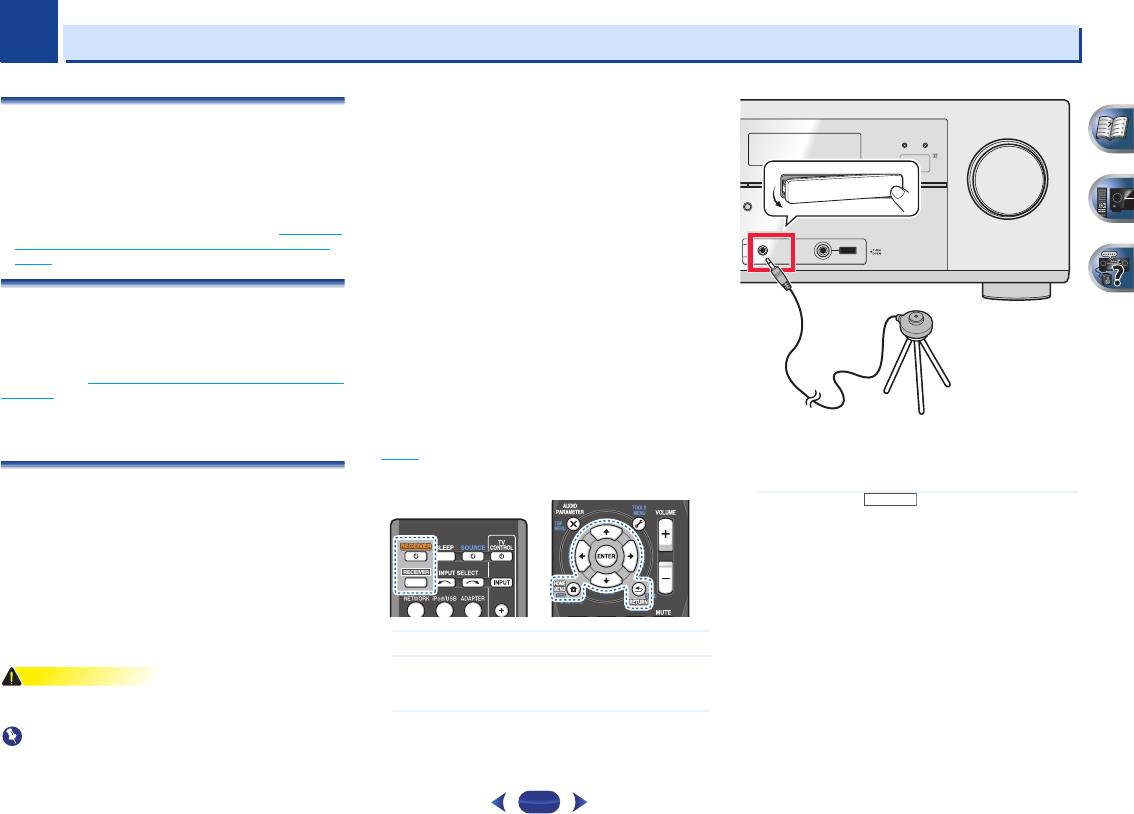
Если у вас есть штатив, используйте его для установки
выполнением автоматической настройки MCACC (см.
микрофона приблизительно на уровне уха в обычной
стр.51
). (Здесь приводится объяснение с помощью экрана
точке прослушивания. Иначе установите микрофон на
дисплея по подключению заднего громкоговорителя
уровне уха, используя стол или стул.
объемного звучания.)
Нажмите кнопку (РЕСИВЕР) на пульте
4
дистанционного управления, после чего нажмите
кнопку HOME MENU.
На телевизоре появляется «Home Menu» (главное меню).
Для перехода между экранами и выделения пунктов меню
используйте кнопки
///
и
ENTER
на пульте
дистанционного управления. Нажмите кнопку
RETURN
(ВОЗВРАТ) для выхода из текущего меню.
•
Нажмите
HOME MENU
в любой момент для выхода из
Включите ресивер и используемый телевизор.
«Home Menu» (главного меню). При отмене
1
автоматической настройки MCACC в любое время
Переключите вход телевизора на вход, с помощью
2
ресивер автоматически выйдет из текущего экрана без
которого данный ресивер подключается к
изменения настроек.
телевизору через соответствующий кабель HDMI.
•
Если в течение трех минут не осуществляются никакие
Подключите микрофон в гнездо
MCACC SETUP MIC
действия, автоматически запускается экранная
3
на передней панели.
заставка.
Проверьте, нет ли препятствий между
•
Экранное меню не появится, если подключение к вашему
громкоговорителями и микрофоном.
телевизору выполнено с помощью композитного выхода.
T
O SURROUND
/
R
CONTROL ON
/
OFF
EAM DIRECT
USB
RECEIVER

3
3
Основная настройка
•
Для обеспечения правильности настроек
Когда ресивер издает дополнительные тестовые звуковые
Выберите «
Auto MCACC
» в «
Home Menu
» (главное
5
громкоговорителей не регулируйте громкость во время
сигналы, чтобы определить оптимальные настройки
меню), затем нажмите ENTER.
тестовых звуковых сигналов.
уровня громкости каналов ресивера, расстояния до
громкоговорителей и эквалайзера акустической
Подтвердите конфигурацию громкоговоритеей.
8
калибровки, на экране отображается сообщение о
Конфигурация, показанная на экране, должна
состоянии.
соответствовать фактическому набору
Во время звучания этих сигналов также старайтесь
громкоговорителей.
соблюдать тишину. Это может занять от 1 до 3 м
инут.
Автоматическая настройка многоканальной
10
акустической калибровки (MCACC) завершена! Вы
возвращаетесь в «
Home Menu
» (главное меню).
•
Mic In! мигает, если микрофон не подключен к гнезду
Параметры автоматической настройки MCACC должны
MCACC SETUP MIC.
обеспечивать превосходное объемное звучание системы,
После нажатия кнопки
ENTER
старайтесь соблюдать
но эти параметры также можно настроить вручную с
тишину. Система сгенерирует ряд тестовых звуковых
помощью «Home Menu» (главного меню) (см. начиная со
сигналов, чтобы определить уровень внешних шумов.
стр.47
).
•
В случае появления сообщений об ошибках (таких как
Следуйте инструкциям, отображаемым на экране.
Too much ambient noise (Слишком высокий уровень
6
•
Убедитесь в том, что микрофон подключен.
фонового шума)), выберите RETRY после проверки
фонового шума (см. Проблемы при использовании
•
Проверьте, что сабвуфер включен и что громкость
звука включена.
автоматической настройки MCACC ниже).
•
При использовании задних громкоговорителей
Если конфигурация громкоговорителей отображается
объемного звучания или передних верхних
неправильно, используйте кнопки
/
, чтобы выбрать
громкоговорителей, включите питание усилителя, к
громкоговоритель, и
/
, чтобы изменить настройку.
которому подключены задние громкоговорители
По окончании перейдите к следующему пункту.
объемного звучания или передние верхние
Возникновение сообщения об ошибке (ERR) в правом
громкоговорители, и отрегулируйте желаемый уровень
столбце может означать неполадку в подключении
воспроизведения звука.
громкоговорителя. Если неполадка не устраняется при
•
Информацию о фоновых шумах и других возможных
выборе пункта RETRY, отключите питание и проверьте
помехах см. ниже.
подключение громкоговорителей.
Для завершения дождитесь тестовых звуковых
7
Убедитесь в том, что выбран пункт «
OK
», затем
сигналов.
9
нажмите ENTER.
Когда ресивер издает тестовые звуковые сигналы, чтобы
Если в шаге 8 не выполнять действия в течение 10 секунд
определить, какие громкоговорители установлены в
и не нажимать кнопку
ENTER
в шаге 9, автоматическая
системе, на экране отображается сообщение о состоянии.
Во время звучания этих сигналов старайтесь соблюдать
настройка MCACC начнется автоматически, как показано
тишину.
ниже.
24
Примечание
Home Menu
Home Menu
1
. Auto MCACC
1
. Auto MCACC
2
. Manual SP Setup
2
. Manual SP Setup
3
. Input Assign
3
. Input Assign
4
. Speaker System
4
. Pre Out Setting
5
. Video Parameter
5
. HDMI Setup
6
. HDMI Setup
6
. Auto Power Down
7
. Auto Power Down
7
. Network Standby
8
. Network Standby
8
. FL Demo Mode
9
. FL Demo Mode
•
Иногда для одинаковых громкоговорителей с диаметром
динамика около 12 см настройка задает разные размеры.
Исправить этот параметр можно вручную, руководствуясь
указаниями раздела Настройка громкоговорителей
на
стр.48.
•
Настройка расстояния до низкочастотного
громкоговорителя может быть больше фактического
расстояния от точки прослушивания. Эта настройка должна
быть точной (с учетом задержки и характеристик
помещения) и обычно не требует изменения.
Проблемы при использовании автоматической
настройки MCACC
Если условия помещения не подходят для автоматической
настройки MCACC (слишком сильные фоновые шумы, эхо от
стен, препятствия, заслоняющие громкоговорители от
микрофона), результаты настройки могут быть неверными.
Проверьте, не влияют ли на эти условия бытовые приборы
(кондиционер, холодильник, вентилятор и т.д.), и при
необходимости отключите их. Если на дисплее передней
панели отображаются как
ие—либо ин
струкции, выполняйте их.
•
Некоторые старые модели телевизоров могут создавать
помехи микрофону. В этом случае выключите телевизор во
время выполнения автоматический настройки MCACC.
1
. Auto MCACC
Check!
Front
[ YES ]
Center
[ YES ]
Surr
[ YES ]
Surr. Back
[
—
]
Subwoofer
[ YES ]
OK
10:Next
Return
1
. Auto MCACC
1
. Auto MCACC
Now Analyzing
Now Analyzing
Environment Check
Surround Analyzing
Ambient Noise
Speaker System
Speaker YES/NO
Speaker Distance
Channel Level
Acoustic Cal EQ
Return
Return
- Manuals
- Brands
- Pioneer Manuals
- Receiver
- VSX-527-K
Manuals and User Guides for Pioneer VSX-527-K. We have 2 Pioneer VSX-527-K manuals available for free PDF download: Quick Start Manual, Service Manual

Pioneer VSX-527-K Quick Start Manual (45 pages)
Brand: Pioneer
|
Category: Receiver
|
Size: 15.99 MB
Table of Contents
-
Connecting the Speaker Cables
2
-
Connecting a TV and Playback Components
3
-
Connecting Antennas
3
-
Connecting to the Network through LAN Interface
3
-
Initial Setup
4
-
Basic Playback
5
-
Multichannel Playback
5
-
Listening to the Radio
5
-
Playing an Ipod
6
-
Listening to Internet Radio Stations
6
-
Raccordement des Enceintes
8
-
Raccordement Au Réseau Par L’interface LAN
9
-
Lecture de Base
11
-
Lecture À Partir D’un Ipod
12
-
Guide de Dépannage
12
-
Anschluss der Lautsprecher
14
-
Anschließen der Lautsprecherkabel
14
-
Herstellen der Verbindung zum Netzwerk über die LAN-Schnittstelle
15
-
Grundlegende Wiedergabe
17
-
Abspielen eines Ipod
18
-
Collegamento Degli Altoparlanti
20
-
Prima DI Cominciare
22
-
Annullare la Schermata Demo
22
-
Impostazione Automatica del Suono Surround (MCACC)
22
-
Riproduzione DI Base
23
-
Ascolto Della Radio
23
-
Riproduzione con un Ipod
24
-
Risoluzione Dei Problemi
24
-
De Luidsprekers Aansluiten
26
-
Aansluiting Van Uw TV en Weerga- Ve-Apparatuur
27
-
Antennes Aansluiten
27
-
Basisbediening Voor Afspelen
29
-
Naar de Radio Luisteren
29
-
Een Ipod Afspelen
30
-
Conexión de Los Cables de Altavoces
32
-
Conexión de Componentes de Reproducción y de un TV
33
-
Conexión de Antenas
33
-
Antes de Comenzar
34
-
Cancelación de la Pantalla Demo
34
-
Confi Guración Automática para Sonido Envolvente (MCACC)
34
-
Reproducción Básica
35
-
Reproducción Multicanal
35
-
Escucha de la Radio
35
-
Reproducción de un Ipod
36
-
Recepción de Emisoras de Radio de Internet
36
Advertisement
Pioneer VSX-527-K Service Manual (5 pages)
Brand: Pioneer
|
Category: Stereo Receiver
|
Size: 0.26 MB
Table of Contents
-
Contrast of Miscellaneous Parts
2
-
Pcb Assemblies
3
-
Packing Section
3
-
Exploded Views
4
-
Exterior Section
4
Advertisement
Related Products
-
Pioneer VSX-527-S
-
Pioneer VSX-528-S
-
Pioneer VSX-5231
-
Pioneer VSX-522-K
-
Pioneer VSX-523-K
-
Pioneer VSX-524-K
-
Pioneer VSX-529-K
-
Pioneer VSX-529-S
-
Pioneer VSX-520-K
-
Pioneer VSX-520
Pioneer Categories
Car Receiver
Receiver
Stereo Receiver
Amplifier
![]()
DVD Player
More Pioneer Manuals

AV Receiver
Operating Instructions
Discover the benefits of registering your product online at http://www.pioneer.co.uk (or http://www.pioneer.eu).
VSX-827
-K/-S
VSX-527
-K/-S
2
.
The exclamation point within an equilateral
triangle is intended to alert the user to the
presence of important operating and
maintenance (servicing) instructions in the
literature accompanying the appliance.
The lightning flash with arrowhead symbol,
within an equilateral triangle, is intended to
alert the user to the presence of uninsulated
“dangerous voltage” within the product’s
enclosure that may be of sufficient
magnitude to constitute a risk of electric
shock to persons.
CAUTION:
TO PREVENT THE RISK OF ELECTRIC
SHOCK, DO NOT REMOVE COVER (OR
BACK). NO USER-SERVICEABLE PARTS
INSIDE. REFER SERVICING TO QUALIFIED
SERVICE PERSONNEL.
CAUTION
RISK OF ELECTRIC SHOCK
DO NOT OPEN
IMPORTANT
D3-4-2-1-1_A1_En
WARNING
This equipment is not waterproof. To prevent a fire or
shock hazard, do not place any container filled with
liquid near this equipment (such as a vase or flower
pot) or expose it to dripping, splashing, rain or
moisture.
D3-4-2-1-3_A1_En
WARNING
Before plugging in for the first time, read the following
section carefully.
The voltage of the available power supply differs
according to country or region. Be sure that the
power supply voltage of the area where this unit
will be used meets the required voltage (e.g., 230 V
or 120 V) written on the rear panel.
D3-4-2-1-4*_A1_En
When installing this unit, make sure to leave space
around the unit for ventilation to improve heat radiation
(at least 40 cm at top, 20 cm at rear, and 20 cm at each
side).
WARNING
Slots and openings in the cabinet are provided for
ventilation to ensure reliable operation of the product,
and to protect it from overheating. To prevent fire
hazard, the openings should never be blocked or
covered with items (such as newspapers, table-cloths,
curtains) or by operating the equipment on thick carpet
or a bed.
D3-4-2-1-7b*_A1_En
WARNING
To prevent a fire hazard, do not place any naked flame
sources (such as a lighted candle) on the equipment.
D3-4-2-1-7a_A1_En
Operating Environment
Operating environment temperature and humidity:
+5 °C to +35 °C (+41 °F to +95 °F); less than 85 %RH
(cooling vents not blocked)
Do not install this unit in a poorly ventilated area, or in
locations exposed to high humidity or direct sunlight (or
strong artificial light)
D3-4-2-1-7c*_A1_En
This product is for general household purposes. Any
failure due to use for other than household purposes
(such as long-term use for business purposes in a
restaurant or use in a car or ship) and which requires
repair will be charged for even during the warranty
period.
K041_A1_En
.
3
If the AC plug of this unit does not match the AC
outlet you want to use, the plug must be removed
and appropriate one fitted. Replacement and
mounting of an AC plug on the power supply cord of
this unit should be performed only by qualified
service personnel. If connected to an AC outlet, the
cut-off plug can cause severe electrical shock. Make
sure it is properly disposed of after removal.
The equipment should be disconnected by removing
the mains plug from the wall socket when left unused
for a long period of time (for example, when on
vacation).
D3-4-2-2-1a_A1_En
CAUTION
The STANDBY/ON switch on this unit will not
completely shut off all power from the AC outlet.
Since the power cord serves as the main disconnect
device for the unit, you will need to unplug it from the
AC outlet to shut down all power. Therefore, make
sure the unit has been installed so that the power
cord can be easily unplugged from the AC outlet in
case of an accident. To avoid fire hazard, the power
cord should also be unplugged from the AC outlet
when left unused for a long period of time (for
example, when on vacation).
D3-4-2-2-2a*_A1_En
Information for users on collection and disposal of old equipment and used batteries
These symbols on the products, packaging, and/or accompanying documents mean
that used electrical and electronic products and batteries should not be mixed with
general household waste.
For proper treatment, recovery and recycling of old products and used batteries,
please take them to applicable collection points in accordance with your national
legislation.
By disposing of these products and batteries correctly, you will help to save valuable
resources and prevent any potential negative effects on human health and the
environment which could otherwise arise from inappropriate waste handling.
For more information about collection and recycling of old products and batteries,
please contact your local municipality, your waste disposal service or the point of sale
where you purchased the items.
These symbols are only valid in the European Union.
For countries outside the European Union:
If you wish to discard these items, please contact your local authorities or dealer and
ask for the correct method of disposal.
K058a_A1_En
Symbol examples
for batteries
Symbol for
equipment
Pb

4
Thank you for buying this Pioneer product. Please read
through these operating instructions so you will know how to
operate your model properly.
Before you start
. . . . . . . . . . . . . . . . . . . . . . . . . . . . . 6
Checking what’s in the box. . . . . . . . . . . . . . . . . . . . . . . . . 6
Installing the receiver . . . . . . . . . . . . . . . . . . . . . . . . . . . . . 6
Flow of settings on the receiver
. . . . . . . . . . . . . . 6
01 Controls and displays
Front panel . . . . . . . . . . . . . . . . . . . . . . . . . . . . . . . . . . . . . 7
Display . . . . . . . . . . . . . . . . . . . . . . . . . . . . . . . . . . . . . . 8
Remote control. . . . . . . . . . . . . . . . . . . . . . . . . . . . . . . . . . 9
Loading the batteries. . . . . . . . . . . . . . . . . . . . . . . . . . . 10
Operating range of remote control . . . . . . . . . . . . . . . . 10
02 Connecting your equipment
Determining the speakers’ application . . . . . . . . . . . . . . . 11
Some tips for improving sound quality . . . . . . . . . . . . . 11
Connecting the speakers . . . . . . . . . . . . . . . . . . . . . . . . . 12
Connect the surround back or front height speakers
(In case of VSX-827). . . . . . . . . . . . . . . . . . . . . . . . . . . . 12
Connect the surround back or front height speakers
(In case of VSX-527). . . . . . . . . . . . . . . . . . . . . . . . . . . . 12
Switching the speaker terminal . . . . . . . . . . . . . . . . . . . 14
Making cable connections . . . . . . . . . . . . . . . . . . . . . . . . 14
HDMI cables . . . . . . . . . . . . . . . . . . . . . . . . . . . . . . . . . 14
About HDMI . . . . . . . . . . . . . . . . . . . . . . . . . . . . . . . . . 14
Analog audio cables . . . . . . . . . . . . . . . . . . . . . . . . . . . 15
Digital audio cables. . . . . . . . . . . . . . . . . . . . . . . . . . . . 15
Video cables . . . . . . . . . . . . . . . . . . . . . . . . . . . . . . . . . 15
About the video converter (VSX-827 only) . . . . . . . . . . . . . 16
About video outputs connection
(VSX-527 only) . . . . . . . . . . . . . . . . . . . . . . . . . . . . . . . . . 16
Connecting a TV and playback components . . . . . . . . . . . 17
Connecting using HDMI . . . . . . . . . . . . . . . . . . . . . . . . 17
Connecting your TV with no HDMI input . . . . . . . . . . . . 18
Connecting your DVD player with no HDMI output
(VSX-827 only) . . . . . . . . . . . . . . . . . . . . . . . . . . . . . . . . 19
Connecting optional Bluetooth
®
ADAPTER . . . . . . . . . . . 20
Connecting to the network through LAN interface . . . . . . 20
Connecting antennas . . . . . . . . . . . . . . . . . . . . . . . . . . . . 21
Using external antennas . . . . . . . . . . . . . . . . . . . . . . . . 21
Connecting a USB device . . . . . . . . . . . . . . . . . . . . . . . . . 21
Connecting an iPod . . . . . . . . . . . . . . . . . . . . . . . . . . . . . 22
Plugging in the receiver . . . . . . . . . . . . . . . . . . . . . . . . . . 22
03 Basic Setup
Canceling the Auto Power Down . . . . . . . . . . . . . . . . . . . 23
Canceling the demo display . . . . . . . . . . . . . . . . . . . . . . . 23
Automatically setting up for surround sound (MCACC) . . 23
Other problems when using the Auto MCACC setup. . . 24
04 Basic playback
Playing a source . . . . . . . . . . . . . . . . . . . . . . . . . . . . . . . . 25
Selecting the audio input signal . . . . . . . . . . . . . . . . . . 25
Playing an iPod . . . . . . . . . . . . . . . . . . . . . . . . . . . . . . . . . 27
Playing back files stored on an iPod . . . . . . . . . . . . . . . 27
Basic playback controls. . . . . . . . . . . . . . . . . . . . . . . . . 27
Watching photos and video content . . . . . . . . . . . . . . . 27
Playing a USB device . . . . . . . . . . . . . . . . . . . . . . . . . . . . 28
Playing back audio files stored on a USB memory
device . . . . . . . . . . . . . . . . . . . . . . . . . . . . . . . . . . . . . . 28
Playing back photo files stored on a USB memory
device . . . . . . . . . . . . . . . . . . . . . . . . . . . . . . . . . . . . . . 28
About playable file formats . . . . . . . . . . . . . . . . . . . . . . 29
Bluetooth
®
ADAPTER for Wireless Enjoyment of Music
. . . 30
Wireless music play. . . . . . . . . . . . . . . . . . . . . . . . . . . . 30
Pairing the Bluetooth ADAPTER and Bluetooth wireless
technology device . . . . . . . . . . . . . . . . . . . . . . . . . . . . . 30
Listening to Music Contents of Bluetooth wireless
technology device with Your System . . . . . . . . . . . . . . . 31
AIR JAM . . . . . . . . . . . . . . . . . . . . . . . . . . . . . . . . . . . . 31
Listening to the radio . . . . . . . . . . . . . . . . . . . . . . . . . . . . 32
Improving FM sound . . . . . . . . . . . . . . . . . . . . . . . . . . . 32
Saving station presets . . . . . . . . . . . . . . . . . . . . . . . . . . 32
Listening to station presets . . . . . . . . . . . . . . . . . . . . . . 32
Naming preset stations . . . . . . . . . . . . . . . . . . . . . . . . . 32
An introduction to RDS. . . . . . . . . . . . . . . . . . . . . . . . . . . 33
Searching for RDS programs. . . . . . . . . . . . . . . . . . . . . 33
Displaying RDS information . . . . . . . . . . . . . . . . . . . . . 33
05 Listening to your system
Choosing the listening mode . . . . . . . . . . . . . . . . . . . . . . 34
Auto playback . . . . . . . . . . . . . . . . . . . . . . . . . . . . . . . . 34
Listening in surround sound . . . . . . . . . . . . . . . . . . . . . 34
Using the Advanced surround . . . . . . . . . . . . . . . . . . . 35
Using Stream Direct . . . . . . . . . . . . . . . . . . . . . . . . . . . 35
Using the Sound Retriever . . . . . . . . . . . . . . . . . . . . . . . . 35
Listening with Acoustic Calibration EQ . . . . . . . . . . . . . . . 35
Better sound using Phase Control . . . . . . . . . . . . . . . . . . 36
Using surround back channel processing. . . . . . . . . . . . . 36
Setting the Up Mix function . . . . . . . . . . . . . . . . . . . . . . . 36
Setting the Audio options . . . . . . . . . . . . . . . . . . . . . . . . . 37
06 Playback with NETWORK features
Introduction . . . . . . . . . . . . . . . . . . . . . . . . . . . . . . . . . . . 39
About playable DLNA network devices. . . . . . . . . . . . . . 39
Using AirPlay on iPod touch, iPhone, iPad, and
iTunes . . . . . . . . . . . . . . . . . . . . . . . . . . . . . . . . . . . . . . 39
About the DHCP server function . . . . . . . . . . . . . . . . . . 39
Authorizing this receiver . . . . . . . . . . . . . . . . . . . . . . . . 39
Playback with Network functions . . . . . . . . . . . . . . . . . . . 40
Basic playback controls . . . . . . . . . . . . . . . . . . . . . . . . . 40
Listening to Internet radio stations. . . . . . . . . . . . . . . . . 40
Playing back audio files stored on components on
the network . . . . . . . . . . . . . . . . . . . . . . . . . . . . . . . . . . 41
Playing back your favorite songs . . . . . . . . . . . . . . . . . . 41
The Network Setup menu . . . . . . . . . . . . . . . . . . . . . . . . . 41
Network Configuration . . . . . . . . . . . . . . . . . . . . . . . . . . 42
Language. . . . . . . . . . . . . . . . . . . . . . . . . . . . . . . . . . . . 43
Firmware Update . . . . . . . . . . . . . . . . . . . . . . . . . . . . . . 43
Factory Reset . . . . . . . . . . . . . . . . . . . . . . . . . . . . . . . . . 43
System Information . . . . . . . . . . . . . . . . . . . . . . . . . . . . 43
About network playback . . . . . . . . . . . . . . . . . . . . . . . . . . 44
Content playable over a network . . . . . . . . . . . . . . . . . . 44
About playback behavior over a network . . . . . . . . . . . . 45
Glossary . . . . . . . . . . . . . . . . . . . . . . . . . . . . . . . . . . . . . . 45
About playable file formats . . . . . . . . . . . . . . . . . . . . . . . . 46
Contents

Contents
5
07 Home Menu
Using the Home Menu . . . . . . . . . . . . . . . . . . . . . . . . . . . 47
Manual speaker setup . . . . . . . . . . . . . . . . . . . . . . . . . . . 47
Speaker Setting. . . . . . . . . . . . . . . . . . . . . . . . . . . . . . . 47
X.Over . . . . . . . . . . . . . . . . . . . . . . . . . . . . . . . . . . . . . . 48
Channel Level . . . . . . . . . . . . . . . . . . . . . . . . . . . . . . . . 49
Speaker Distance . . . . . . . . . . . . . . . . . . . . . . . . . . . . . 49
The Input Assign menu . . . . . . . . . . . . . . . . . . . . . . . . . . 50
Analog Input . . . . . . . . . . . . . . . . . . . . . . . . . . . . . . . . . 50
Component Input (VSX-827 only) . . . . . . . . . . . . . . . . . . 50
The Speaker System setting (VSX-827 only) . . . . . . . . . . . 50
The Video Parameter setting (VSX-827 only) . . . . . . . . . . . 50
Video Converter. . . . . . . . . . . . . . . . . . . . . . . . . . . . . . . 50
Resolution. . . . . . . . . . . . . . . . . . . . . . . . . . . . . . . . . . . 51
Aspect. . . . . . . . . . . . . . . . . . . . . . . . . . . . . . . . . . . . . . 51
The Pre Out Setting (VSX-527 only) . . . . . . . . . . . . . . . . . . 51
The Auto Power Down menu . . . . . . . . . . . . . . . . . . . . . . 52
The Network Standby menu . . . . . . . . . . . . . . . . . . . . . . . 52
The FL Demo Mode menu . . . . . . . . . . . . . . . . . . . . . . . . 52
08 Control with HDMI function
Making Control with HDMI connections. . . . . . . . . . . . . . 53
HDMI Setup . . . . . . . . . . . . . . . . . . . . . . . . . . . . . . . . . . . 53
Before using synchronization . . . . . . . . . . . . . . . . . . . . . . 54
About synchronized operations . . . . . . . . . . . . . . . . . . . . 54
Cautions on the Control with HDMI function . . . . . . . . . . 54
09 Controlling the rest of your system
Setting the remote to control other components . . . . . . . 55
Selecting preset codes directly. . . . . . . . . . . . . . . . . . . . . 55
Clearing all the remote control settings . . . . . . . . . . . . . . 55
Controls for TVs . . . . . . . . . . . . . . . . . . . . . . . . . . . . . . . . 56
Controls for other components. . . . . . . . . . . . . . . . . . . . . 56
Preset Code List . . . . . . . . . . . . . . . . . . . . . . . . . . . . . . . . 56
10 Additional information
Troubleshooting . . . . . . . . . . . . . . . . . . . . . . . . . . . . . . . . 62
General . . . . . . . . . . . . . . . . . . . . . . . . . . . . . . . . . . . . . 62
NETWORK feature . . . . . . . . . . . . . . . . . . . . . . . . . . . . . 63
HDMI. . . . . . . . . . . . . . . . . . . . . . . . . . . . . . . . . . . . . . . 64
Important information regarding the HDMI
connection . . . . . . . . . . . . . . . . . . . . . . . . . . . . . . . . . . 64
Windows 7 . . . . . . . . . . . . . . . . . . . . . . . . . . . . . . . . . . . . 65
About iPod/iPhone/iPad . . . . . . . . . . . . . . . . . . . . . . . . . . 65
About FLAC . . . . . . . . . . . . . . . . . . . . . . . . . . . . . . . . . . . 65
About messages displayed when using network
functions . . . . . . . . . . . . . . . . . . . . . . . . . . . . . . . . . . . . . 66
Resetting the main unit . . . . . . . . . . . . . . . . . . . . . . . . . . 66
Cleaning the unit . . . . . . . . . . . . . . . . . . . . . . . . . . . . . . . 66
Specifications . . . . . . . . . . . . . . . . . . . . . . . . . . . . . . . . . . 67
6
Before you start
Checking what’s in the box
Please check that you’ve received the following supplied
accessories:
•
Setup microphone
•
Remote control
•
AAA size IEC R03 dry cell batteries (to confirm system
operation) x2
•
AM loop antenna
•
FM wire antenna
•
Power cord
•
iPod cable (VSX-827 only)
•
Warranty card
•
Quick start guide
•
Safety Brochure
•
These operating instructions (CD-ROM)
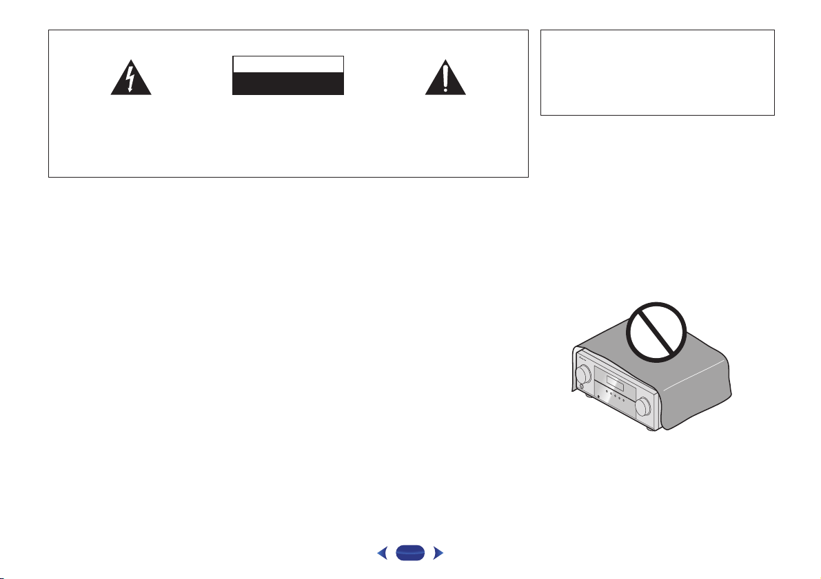
Installing the receiver
•
When installing this unit, make sure to put it on a level and
stable surface.
Don’t install it on the following places:
– on a color TV (the screen may distort)
– near a cassette deck (or close to a device that gives off a
magnetic field). This may interfere with the sound.
– in direct sunlight
– in damp or wet areas
– in extremely hot or cold areas
– in places where there is vibration or other movement
– in places that are very dusty
– in places that have hot fumes or oils (such as a kitchen)
Flow of settings on the receiver
The unit is a full-fledged AV receiver equipped with an
abundance of functions and terminals. It can be used easily
after following the procedure below to make the connections
and settings.
The colors of the steps indicate the following:
— — — — — — — — — — — — — — — — — — — — — — — — — — — — — — — — — — — — — — — — — —
Required setting item
Setting to be made as necessary
1
Connecting the speakers
Where you place the speakers will have a big effect on
the sound.
•
Determining the speakers’ application (page 11)
•
Connecting the speakers (page 12)
•
Switching the speaker terminal (page 14)
2
Connecting the components
For surround sound, you’ll want to hook up using a
digital connection from the Blu-ray Disc/DVD player to
the receiver.
•
About the video converter (VSX-827 only) (page 16)
•
About video outputs connection (VSX-527 only)
(page 16
)
•
Connecting a TV and playback components (page 17)
•
Connecting antennas (page 21)
•
Plugging in the receiver (page 22)
3
Power On
Make sure you’ve set the video input on your TV to this
receiver. Check the manual that came with the TV if you
don’t know how to do this.
4
The Speaker System setting (VSX-827 only) (page 50)
(Specify either using the surround back or front height
speaker.)
The Pre Out Setting (VSX-527 only) (page 51
)
(When connecting the front height speakers.)
The Input Assign menu (page 50
)
(When using connections other than the recommended
connections.)
HDMI Setup (page 53
)
(When the connected TV supports the HDMI Audio Return
Channel function.)
5
Use the on-screen automatic MCACC setup to set up
your system
•
Automatically setting up for surround sound (MCACC)
(page 23
)
6
Basic playback (page 25)
•
Selecting the audio input signal (page 25)
•
Playing an iPod (page 27)
•
Playing a USB device (page 28)
•
Choosing the listening mode (page 34)
7
Adjusting the sound as desired
•
Using the Sound Retriever (page 35)
•
Better sound using Phase Control (page 36)
•
Listening with Acoustic Calibration EQ (page 35)
•
Using surround back channel processing (page 36)
•
Setting the Up Mix function (page 36)
•
Setting the Audio options (page 37)
•
Manual speaker setup (page 47)
8
Making maximum use of the remote control
•
Setting the remote to control other components
(page 55
)
1
1
Chapter
7
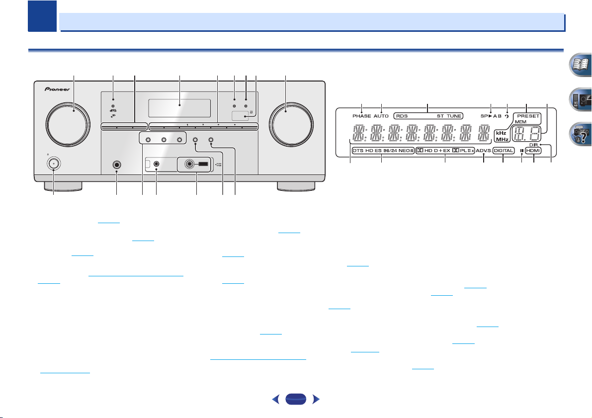
Controls and displays
Front panel
1
INPUT SELECTOR
dial
Selects an input source (page 25).
2
MCACC indicator
Lights when Acoustic Calibration EQ (page 35) is on (Acoustic
Calibration EQ is automatically set to on after the Auto
MCACC setup (page 23
)).
3
Receiver control buttons
SPEAKERS
– See Switching the speaker terminal on
page 14.
DIMMER
– Dims or brightens the display. The brightness
can be controlled in four steps.
DISPLAY
– Switches the display of this unit. The listening
mode, sound volume, Speaker System (VSX-827)/Pre Out
(VSX-527) setting or input name can be checked by
selecting an input source.
• The Speaker System/Pre Out setting may or may not be
displayed, depending on the input source you have
selected.
4
Character display
See Display on page 8.
5
Tuner control buttons
BAND
– Switches between AM, FM ST (stereo) and FM
MONO radio bands (page 32
).
TUNER EDIT
– Use with
TUNE
/
,
PRESET
/
and
ENTER
to memorize and name stations for recall
(page 32
).
TUNE
/
– Used to find radio frequencies (page 32).
PRESET
/
– Use to select preset radio stations
(page 32
).
6
HDMI indicator
Blinks when connecting an HDMI-equipped component;
lights when the component is connected (page 17
).
7
iPod iPhone iPad indicator
Lights when an iPod/iPhone/iPad is connected and
iPod/USB
input is selected (page 27
).
8
Remote sensor
Receives the signals from the remote control (see Operating
range of remote control on page 10).
9
MASTER VOLUME
dial
10
STANDBY/ON
11
PHONES jack
Use to connect headphones. When the headphones are
connected, there is no sound output from the speakers. The
listening mode when the sound is heard from the headphone
can be selected only from PHONES SURR, STEREO or
STEREO ALC mode (S.R AIR mode can be also selected with
ADAPTER input).
12
Listening mode buttons
AUTO SURROUND/STREAM DIRECT
– Switches between
Auto surround mode (page 34
) and Stream Direct
playback (page 35
).
ALC/STANDARD SURR
– Press for standard decoding
and to switch between the modes of 2 Pro Logic II, 2
Pro Logic IIx, 2 Pro Logic IIz and NEO:6, and the Auto
level control stereo mode (page 34
).
ADVANCED SURROUND
– Switches between the various
surround modes (page 35
).
13
MCACC SETUP MIC jack
Use to connect a microphone when performing Auto MCACC
setup (page 23
).
MASTER
VOLUME
STANDBY/ON
INPUT
SELECTOR
iPod iPhone iPad
DIRECT CONTROL
SOUND
RETRIEVER AIR
ADVANCED
SURROUND
PHONES
SPEAKERS DIMMER DISPLAY BAND TUNER EDIT TUNE PRESET ENTER
HDMIMCACC
iPod iPhone iPad
ALC/
STANDARD SURR
AUTO SURROUND
/
STREAM DIRECT
456
10
11 12
2
1 7 938
MCACC
SETUP
MIC
VIDEO
iPod
iPhone
iPad
USB
1513 14 16
17 18 19 20 21 19
24 25 26 27 27 2928
22
23
Controls and displays
1
1
8
14
iPod iPhone iPad/USB terminal
Use to connect your Apple iPod or USB mass storage device
as an audio source (page 22
).
15
SOUND RETRIEVER AIR
When the button is pressed, the input switches to ADAPTER
and the listening mode is automatically set to S.R AIR
(page 31
).
16
iPod iPhone iPad DIRECT CONTROL
Change the receiver’s input to the iPod and enable iPod
operations on the iPod (page 28
).
Display
17
PHASE
Lights when the Phase Control is switched on (page 36).
18
AUTO
Lights when the Auto Surround feature is switched on
(page 34
).
19
Tuner indicators
RDS – Lights when an RDS broadcast is received
(page 33
).
ST – Lights when a stereo FM broadcast is being received
in auto stereo mode (page 32
).
TUNE – Lights when a normal broadcast channel.
PRESET – Shows when a preset radio station is registered
or called.
MEM – Blinks when a radio station is registered.
kHz/MHz – Lights when the character display is showing
the currently received AM/FM broadcast frequency.
20
Speaker indicators
Shows if the speaker system is on or not (page 14).
21
Sleep timer indicator
Lights when the receiver is in sleep mode (page 9).
22
PRESET information or input signal indicator
Shows the preset number of the tuner or the input signal type,
etc.
23
Character display
Displays various system information.
24
DTS indicators
DTS – Lights when a source with DTS encoded audio
signals is detected.
HD – Lights when a source with DTS-EXPRESS or DTS-HD
encoded audio signals is detected.
ES – Lights to indicate DTS-ES decoding.
96/24 – Lights when a source with DTS 96/24 encoded
audio signals is detected.
NEO:6 – When one of the NEO:6 modes of the receiver is
on, this lights to indicate NEO:6 processing (page 34
).
25
Dolby Digital indicators
2 D – Lights when a Dolby Digital encoded signal is
detected.
2 D+ – Lights when a source with Dolby Digital Plus
encoded audio signals is detected.
2HD – Lights when a source with Dolby TrueHD encoded
audio signals is detected.
EX – Lights to indicate Dolby Digital EX decoding.
2PLII(x) – Lights to indicate 2 Pro Logic II/2 Pro Logic
IIx decoding. Light will go off during 2 Pro Logic IIz
decoding (see Listening in surround sound
on page 34 for
26
ADV.S.
Lights when one of the Advanced Surround modes has been
selected (see Using the Advanced surround
on page 35 for
27
SIGNAL SELECT indicators
DIGITAL – Lights when a digital audio signal is selected.
Blinks when a digital audio signal is selected and selected
audio input is not provided.
HDMI – Lights when an HDMI signal is selected. Blinks
when an HDMI signal is selected and selected HDMI input
is not provided.
28
Up Mix/DIMMER indicator
Lights when the Up Mix function is set to ON (page 36). Also,
lights when DIMMER is set to off.
29
DIR.
Lights when the DIRECT or PURE DIRECT mode is switched
on (page 35
).
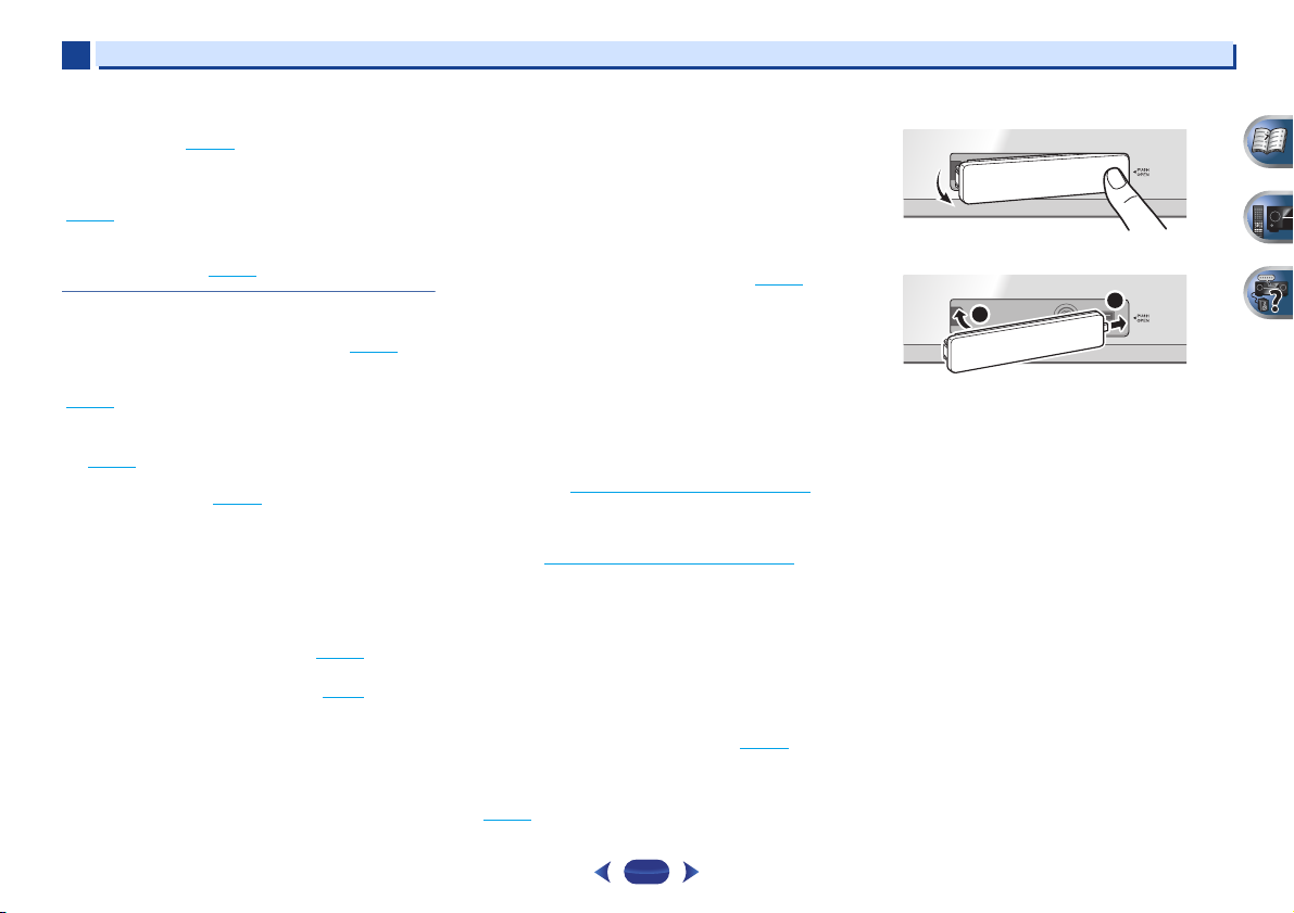
Removing the front cover
Attaching the front cover
MCACC
SETUP
MIC
VIDEO
iPod
iPhone
iPad
USB
5 V
2.1
A
MCACC
SETUP
MIC
VIDEO
iPod
iPhone
iPad
USB
1
2
Controls and displays
1
1
9
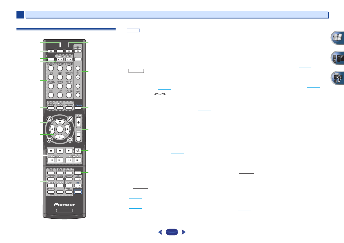
Remote control
•
button is not used with this receiver.
1
SLEEP
Press to change the amount of time before the receiver
switches into standby (30 min – 60 min – 90 min – Off). You
can check the remaining sleep time at any time by pressing
SLEEP
once.
2
RECEIVER
Switches the receiver between standby and on.
3
Switches the remote to control the receiver (used to select the
white commands above the number buttons (
MIDNIGHT
,
etc)). Also use this button to set up surround sound (page 47
)
or Audio parameters (page 37
).
4
INPUT SELECT
Use to select the input source (page 25).
5
Input function buttons
Use to select the input source to this receiver (page 25). This
will enable you to control other components with the remote
control (page 55
).
6
Listening mode buttons
AUTO/DIRECT
– Switches between Auto surround mode
(page 34
) and Stream Direct playback (page 35).
ALC/STANDARD SURR
– Press for standard decoding
and to switch between the modes of 2 Pro Logic II, 2
Pro Logic IIx, 2 Pro Logic IIz and NEO:6, and the Auto
level control stereo mode (page 34
).
ADV SURR
– Switches between the various surround
modes (page 35
).
7
Receiver and component control buttons
The following button controls can be accessed after you have
selected the corresponding input function button (
BD
,
DVD
,
etc.).
Press first to access:
AUDIO PARAMETER
– Use to access the Audio options
(page 37
).
HOME MENU
– Press to access the Home Menu
(page 47
).
RETURN
– Confirm and exit the current menu screen.
Press
BD
,
DVD
or
DVR/BDR
first to access:
TOP MENU
– Displays the disc ‘top’ menu of a Blu-ray
Disc/DVD.
HOME MENU
– Displays the HOME MENU screen.
RETURN
– Confirm and exit the current menu screen.
MENU
– Display s the TOOLS menu of Blu-ray Disc player.
Press
TUNER
first to access:
TOOLS
– Memorizes stations for recall (page 32), also
used to change the name (page 32
).
BAND
– Switches between AM, FM ST (stereo) and FM
MONO radio bands (page 32
).
PTY
– Use to search for RDS program types (page 33).
Press
iPod/USB
first to access:
iPod CTRL
– Switches between the iPod controls and the
receiver controls (page 27
).
8
///
(
TUNE
/
,
PRESET
/
),
ENTER
Use the arrow buttons when setting up your surround sound
system (page 47
). Also used to control Blu-ray Disc/DVD
menus/options.
Use
TUNE
/
can be used to find radio frequencies and
PRESET
/
can be used to select preset radio stations
(page 32
).
9
Component control buttons
The main buttons (
,
, etc.) are used to control a component
after you have selected it using the input function buttons.
The controls above these buttons can be accessed after you
have selected the corresponding input function button (
BD
,
DVD
and
CD
). These buttons also function as described
below.
Press first to access:
BASS +/–
,
TRE +/–
– Use to adjust Bass or Treble.
• These controls are disabled when the listening mode is
set to DIRECT or PURE DIRECT.
• When the front speaker is set at SMALL in the Speaker
Setting (or automatically via the Auto MCACC setup)
and the X.Over is set above 150 Hz, the subwoofer
channel level will be adjusted by pressing
BASS +/–
(page 48
).
SLEEP
INPUT
1
4
7
RECEIVER
ENTER
2
5
8
DISP
CLR
3
6
9
0
ENTER
CH
CH
MUTE
RETURN
AUDIO
PARAMETER
MENU
HOME
MENU
RECEIVER
RECEIVER
SOURCE
TOOLS
BAND
iPod CTRL
PTY
TOP
MENU
T
U
N
E
T
U
N
E
P
R
E
S
E
T
P
R
E
S
E
T
SHIFT
1
2
11
12
13
14
15
16
3
4
5
6
7
8
9
10
SHIFT
RECEIVER
RECEIVER
Controls and displays
1
1
10
10
Number buttons and other component controls
Use the number buttons to directly select a radio frequency
(page 32
) or the tracks on a CD, etc. There are other buttons
that can be accessed after is pressed. (For example
MIDNIGHT
, etc.)
EQ
– Press to switch on/off Acoustic Calibration EQ
setting (page 35
).
PHASE
– Press to switch on/off Phase Control (page 36).
SIGNAL SEL
– Press to select the audio input signal of the
component to play back (page 25
).
S.RETRIEVER
– Press to restore CD quality sound to
compressed audio sources (page 35
).
SB CH
– Press to select ON, AUTO or OFF the surround
back channel (page 36
).
CH SELECT
– Press repeatedly to select a channel, then
use
LEV +/–
to adjust the level (page 49).
LEV +/–
– Use to adjust the channel level.
MIDNIGHT
– Switches to Midnight or Loudness listening
(page 37
).
SPEAKERS
– See Switching the speaker terminal on
page 14.
DIMMER
– Dims or brightens the display. The brightness
can be controlled in four steps.
11
SOURCE
Press to turn on/off other components connected to the
receiver (page 55
).
12
TV CONTROL buttons
These buttons are dedicated to control the TV assigned to the
TV
button. Thus if you only have one TV to hook up to this
system assign it to the
TV
button (page 56).
– Use to turn on/off the power of the TV.
INPUT
– Use to select the TV input signal.
CH +/–
– Use to select channels.
VOL +/–
– Use to adjust the volume on your TV.
13
+Favorite
Press while a song is being played back or stopped. The
selected song is then registered in the Favorites folder
(page 41
).
14
VOLUME +/–
Use to set the listening volume.
15
MUTE
Mutes/unmutes the sound.
16
DISP
Switches the display of this unit. The listening mode, sound
volume, Speaker System (VSX-827)/Pre Out (VSX-527) setting or
input name can be checked by selecting an input source.
•
The Speaker System/Pre Out setting may or may not be
displayed, depending on the input source you have
selected.
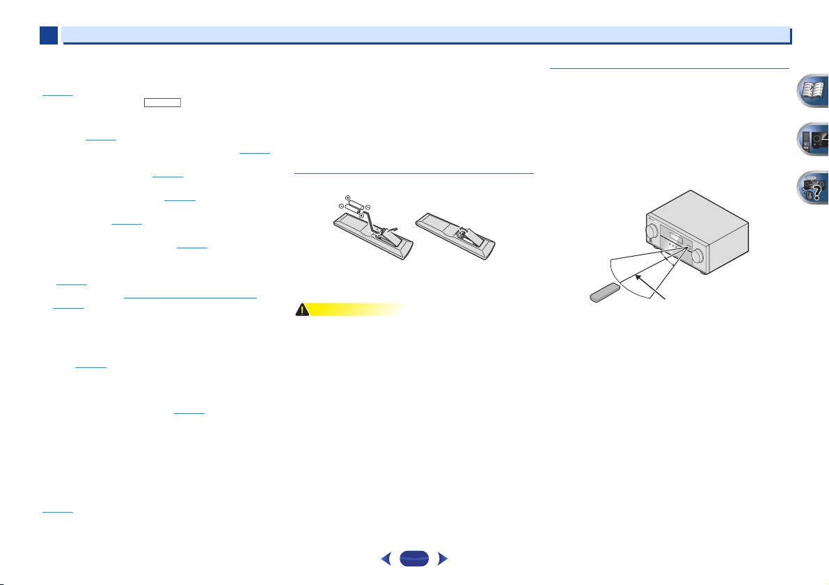
Loading the batteries
The batteries included with the unit are to check initial
operations; they may not last over a long period. We
recommend using alkaline batteries that have a longer life.
•
Incorrect use of batteries may result in such hazards as
leakage and bursting. Observe the following precautions:
—
Never use new and old batteries together.
—
Insert the plus and minus sides of the batteries properly
according to the marks in the battery case.
—
Batteries with the same shape may have different
voltages. Do not use different batteries together.
—
When disposing of used batteries, please comply with
governmental regulations or environmental public
instruction’s rules that apply in your country or area.
—
Do not use or store batteries in direct sunlight or other
excessively hot place, such as inside a car or near a
heater. This can cause batteries to leak, overheat,
explode or catch fire. It can also reduce the life or
performance of batteries.
Operating range of remote control
The remote control may not work properly if:
•
There are obstacles between the remote control and the
receiver’s remote sensor.
•
Direct sunlight or fluorescent light is shining onto the
remote sensor.
•
The receiver is located near a device that is emitting
infrared rays.
•
The receiver is operated simultaneously with another
infrared remote control unit.
RECEIVER
2
2
11
Chapter
Connecting your equipment
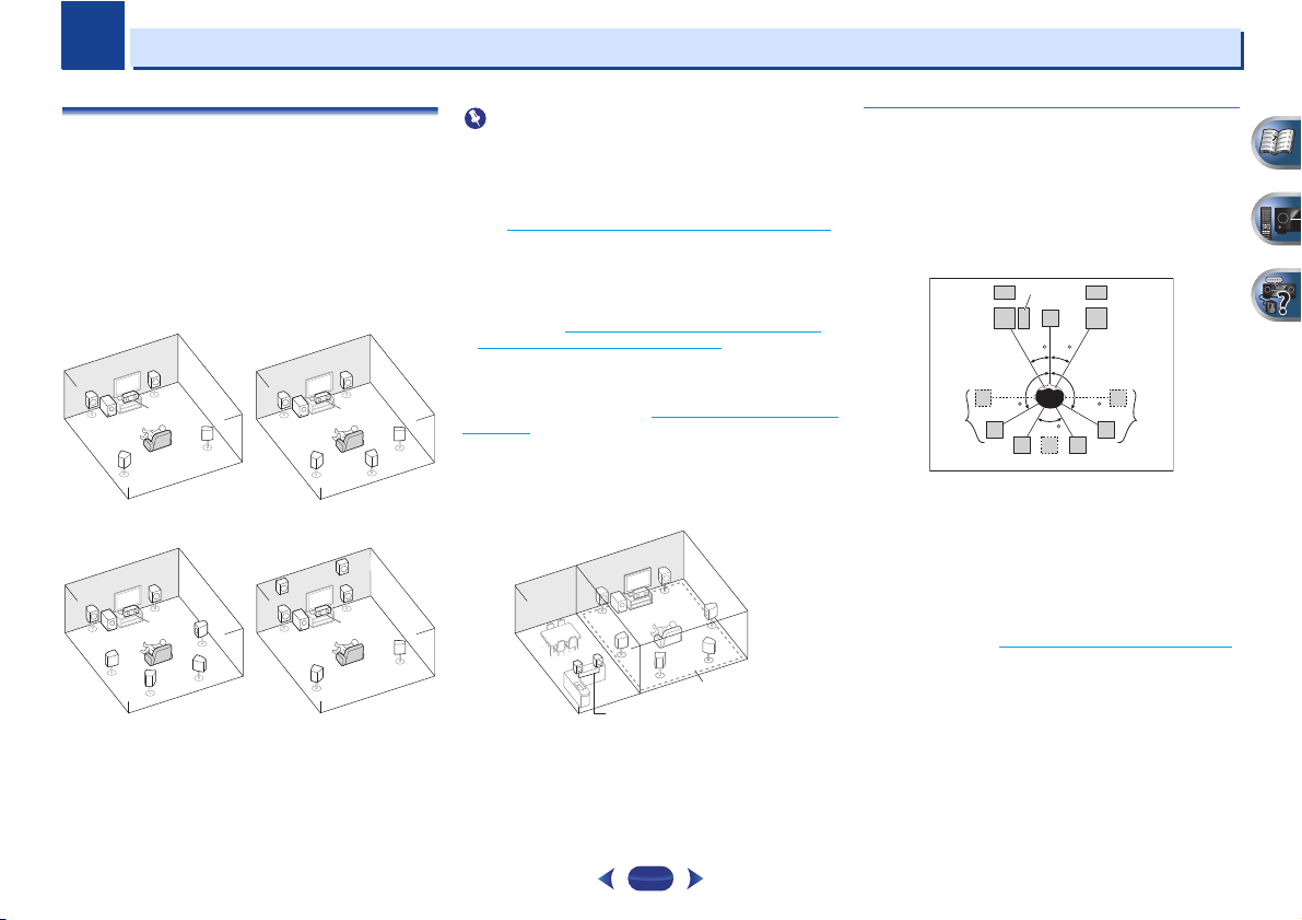
Determining the speakers’ application
By connecting the left and right front speakers (L/R), the
center speaker (C), the left and right surround speakers (SL/
SR), the left and right surround back speakers (SBL/SBR) (or
the left and right front height speakers (FHL/FHR)), and the
subwoofer (SW), a surround sound system up to 7.1 channel
can be enjoyed.
The 5.1 channel surround system is the most commonly-used
in home theaters. To achieve the best possible surround
sound, install your speakers as shown below.
•
VSX-827 only: Both the surround back speakers and the
front height speakers can be connected at the same time.
In this case, sound will be output from either the front
height speaker or the surround back speaker depending on
which one was selected in the Speaker System setting
(see The Speaker System setting (VSX-827 only)
on page 50).
•
VSX-527 only: To connect the surround back or front
height speakers, an additional amplifier is required.
Connect the additional amplifier to the PRE OUT SURR
BACK/FRONT HEIGHT outputs of this unit and connect the
surround back or front height speakers to the additional
amplifier (see Connect the surround back or front height
speakers (In case of VSX-527) on page 12).
VSX-827 only: Another way, you can use the speakers
connected to the B speaker terminals to listen to stereo
playback in another room. See Switching the speaker terminal
on page 14 for the listening options with this setup.
•
You will not be able to connect the B speakers if you
connect the front height speakers in the main zone.
Further, if you use the B speakers, a 5.1 ch playback will be
the maximum in the main zone. (No sound is output from
the surround back speaker.)
Some tips for improving sound quality
Where you put your speakers in the room has a big effect on
the quality of the sound. The following guidelines should help
you to get the best sound from your system.
•
It is best to angle the speakers towards the listening
position. The angle depends on the size of the room. Use
less of an angle for bigger rooms.
•
Refer to the chart below for placement of speakers you
intend to connect.
—
Place the surround speakers at 120º from the center. If
you, (1) use the surround back speaker, and, (2) don’t use
the front height speakers, we recommend placing the
surround speaker right beside you.
—
If you intend to connect only one surround back
speakers, place it directly behind you.
—
If the surround speakers cannot be set directly to the side
of the listening position with a 7.1-channel system, the
surround effect can be enhanced by turning off the Up
Mix function (see Setting the Up Mix function
on page 36).
•
For the best stereo effect, place the front speakers 2 m to
3 m apart, at equal distance from the TV.
•
If you’re using a center speaker, place the front speakers at
a wider angle. If not, place them at a narrower angle.
•
Place the center speaker above or below the TV so that the
sound of the center channel is localized at the TV screen.
Also, make sure the center speaker does not cross the line
formed by the leading edge of the front left and right
speakers.
SL
L
SW
C
RR
SR
SL
L
SW
C
SR
SB
5.1 channel surround
system:
6.1 channel surround
(Surround back) system:
C
SL
L
FHL
FHR
SW
R
SR
SL
L
SW
C
R
SR
SBL
SBR
7.1 channel surround
(Surround back) system:
7.1 channel surround
(Front height) system:
L
R
L
SW
C
FHL
SL
SBL
SBR
SB
SR
R
FHR
30 30
60
120 120
Connecting your equipment
2
2
12
•
Surround and surround back speakers should be
positioned 60 cm to 90 cm higher than your ears and titled
slight downward. Make sure the speakers don’t face each
other. For DVD-Audio, the speakers should be more directly
behind the listener than for home theater playback.
•
Try not to place the surround speakers farther away from
the listening position than the front and center speakers.
Doing so can weaken the surround sound effect.
•
Place the left and right front height speakers at least one
meter directly above the left and right front speakers.
•
If you’re going to place speakers around your CRT TV, use
shielded speakers or place the speakers at a sufficient
distance from your CRT TV.
•
The subwoofer can be placed on the floor. Ideally, the other
speakers should be at about ear-level when you’re listening
to them. Putting the speakers on the floor (except the
subwoofer), or mounting them very high on a wall is not
recommended.
•
When not connecting a subwoofer, connect speakers with
low frequency reproduction capabilities to the front
channel. (The subwoofer’s low frequency component is
played from the front speakers, so the speakers could be
damaged.)
•
After connecting, be sure to conduct the Auto MCACC
(speaker environment setting) procedure.
See Automatically setting up for surround sound (MCACC)
on page 23.
•
Make sure that all speakers are securely installed. This not
only improves sound quality, but also reduces the risk of
damage or injury resulting from speakers being knocked
over or falling in the event of external shocks such as
earthquakes.
Connecting the speakers
The receiver will work with just two stereo speakers (the front
speakers in the diagram) but using at least three speakers is
recommended, and a complete setup is best for surround
sound.
Make sure you connect the speaker on the right to the right (R)
terminal and the speaker on the left to the left (L) terminal.
Also make sure the positive and negative (+/–) terminals on
the receiver match those on the speakers.
You can use speakers with a nominal impedance between 6 Ω
and 16 Ω.
Be sure to complete all connections before connecting this unit
to the AC power source.
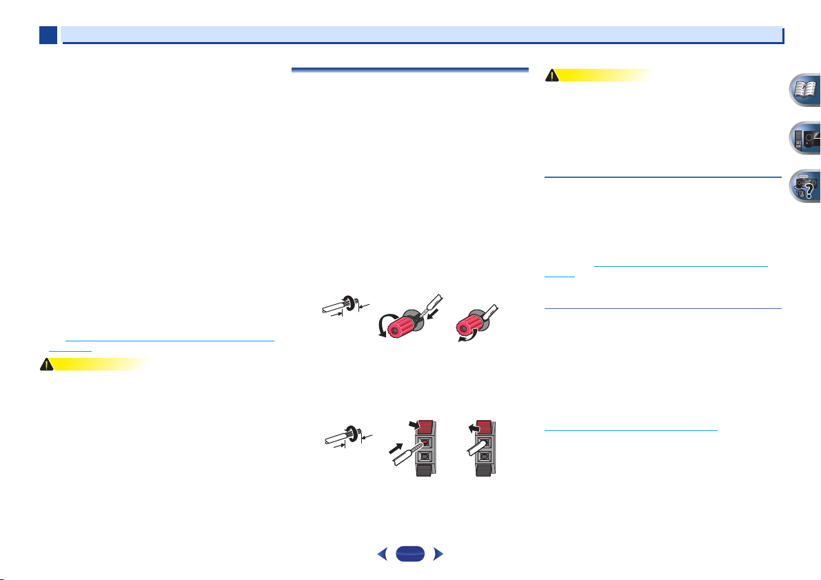
Bare wire connections
1
Twist exposed wire strands together.
2
Loosen terminal and insert exposed wire.
3
Tighten terminal.
Connect the wires to the B-Speakers terminals of the VSX-827 as
shown below:
1
Twist exposed wire strands together.
2
Push open the tabs and insert exposed wire.
3
Release the tabs.
•
These speaker terminals carry HAZARDOUS LIVE voltage.
To prevent the risk of electric shock when connecting or
disconnecting the speaker cables, disconnect the power
cord before touching any uninsulated parts.
•
Make sure that all the bare speaker wire is twisted together
and inserted fully into the speaker terminal. If any of the
bare speaker wire touches the back panel it may cause the
power to cut off as a safety measure.
Connect the surround back or front height
speakers (In case of VSX-827)
The Speaker System setting must be set if the above
connections are performed. Select Surr.Back if the surround
back speaker is connected and Height if the front height
speaker is connected (If neither the surround back speaker
nor the front height speaker is connected, either setting will
suffice) (see The Speaker System setting (VSX-827 only)
on
page 50).
•
When using only one surround back speaker, connect it to
the SURROUND BACK L (Single) terminals.
Connect the surround back or front height
speakers (In case of VSX-527)
Connect the PRE OUT SURR BACK/FRONT HEIGHT outputs
of the unit and additional amplifier to add a surround back or
front height speaker.
The Pre Out setting must be set if the above connections are
performed. Select Surr.Back if the surround back speaker is
connected and Height if the front height speaker is
connected (If neither the surround back speaker nor the front
height speaker is connected, either setting will suffice) (see
The Pre Out Setting (VSX-527 only)
on page 51).
•
You can use the additional amplifier on the surround back
channel pre-outs for a single speaker as well. In this case
plug the amplifier into the left (L (Single)) terminal only.
12 3
12 3
Connecting your equipment
2
2
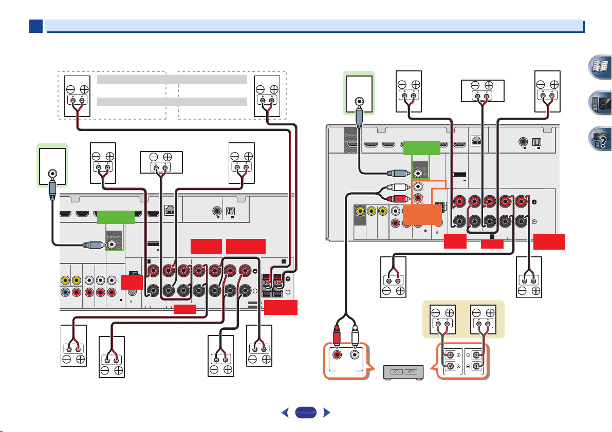
13
VSX-827 connection diagram VSX-527 connection diagram
R
L
AUDIO
NENT VIDEO
PRE OUT
SPEAKERS
ANTENNA
OPTICAL
COAXIAL
LAN
(
10/100
)
DVD
IN
SAT/CBL
IN
DVD
PB PR
SAT/CBL
ANALOG IN
IN
IN
DVD GAME VIDEOBD
SAT/CBL DVR/BDR
(
CD
)
(
TV
)
IN
1
IN
1
(
CD
)
ASSIGNABLE
ASSIGNABLE
ASSIGNABLE
1
FM UNBAL
75
CAUTION:
ATTENTION:
SPEAKER IMPEDANCE
ENCEINTE D’IMPEDANCE DE
SEE INSTRUCTION MANUAL
VOIR LE MODE D’EMPLOI
6 -16 .
6 -16 .
AM LOOP
SURROUND
SURROUND BACK FRONT HEIGHT
/
CENTER
FRONT
RL
RL
RL
(
Single
)
RL
A
B
SUB WOOFER
1
(
OUTPUT 5
V
0.1 A MAX
)
ADAPTER PORT
SELECTABLE
SELECTABLE
LINE LEVEL
INPUT
FRONT
R L
SURROUND
R L
FRONT HEIGHT
R L
CENTER
PREOUT
SUBWOOFER
SURROUND BACK
R L
Front height setting
Speaker B setting
Front right
Subwoofer
Center
Front left
Surround right
Surround left
Surround
back right
Surround
back left
Front height right
Speaker B — right
Front height left
Speaker B — left
The front height terminals can also be used for Speaker B.
When using only one surround back speaker, connect it
to the SURROUND BACK L (Single) terminals.
HDMI
VIDEO
R
L
AUDIO
PRE OUT
SPEAKERS
ANTENNA
OPTICAL
COAXIAL
LAN
(
10/100
)
DVD
IN
SAT/CBL
IN
MONITOR
OUT
DVD
SAT/CBL
ANALOG IN
IN
R
L
PRE OUT
SURR BACK/
FRONT HEIGHT
IN
DVD GAME VIDEOBD
SAT/CBL DVR/BDR
(
CD
)
(
Single
)
(
TV
)
IN
1
IN
1
(
CD
)
OUT
ASSIGNABLE
ASSIGNABLE
ASSIGNABLE
1
FM UNBAL
75
CAUTION:
ATTENTION:
SPEAKER IMPEDANCE
ENCEINTE D’IMPEDANCE DE
Class 2 Wiring
6 -16 .
6 —16 .
AM LOOP
SURROUND
CENTER
FRONT
RL
RL
A
SUB WOOFER
1
(
OUTPUT 5
V
0.1 A MAX
)
ADAPTER PORT
LINE LEVEL
INPUT
SPEAKER R SPEAKER L
PREOUT
SURR BACK/
FRONT HEIGHT
FRONT
R L
SURROUND
R L
CENTER
PREOUT
SUBWOOFER
RL
ANALOG
AUDIO IN
Center
Surround right
Front right
Front left
Subwoofer
Surround left
Right
Surround back or
front height speakers
Surround back or front height
channel amplifier
Left
Connecting your equipment
2
2
14
Switching the speaker terminal
Use
SPEAKERS
button to change the speaker system on or
off. When the SP OFF is selected, no sound is output from the
speakers connected to this receiver.
VSX-827 only: If you selected Surr.Back in The Speaker System
setting (VSX-827 only) on page 50, you can switch between
speakers using the
SPEAKERS
button. If you selected Height,
the button will simply switch your main speaker terminal on or
off. The options below are for the Surr.Back setting only.
Use the
SPEAKERS
button on the front panel to select a
speaker terminal setting.
Press repeatedly to choose a speaker terminal option:
•
SPA – Sound is output from the speakers connected to
the A-speaker terminals and PRE OUT SURR BACK/FRONT
HEIGHT (VSX-527 only) (multichannel playback is possible).
•
SPB (VSX-827 only) – Sound is output from the two
speakers connected to the B-speaker terminals (only stereo
playback is possible).
•
SPAB (VSX-827 only) – Sound is output from the A-
speaker terminals, the two speakers in the B-speaker
terminals, and the subwoofer. Multichannel sources are
downmixed only when the STEREO or STEREO ALC mode
is selected for stereo output from A- and B-speaker
terminals.
•
SP – No sound is output from the speakers.
•
VSX-827 only: The subwoofer output depends on the
settings you made in Speaker Setting
on page 47. However,
if SPB is selected above, no sound is heard from the
subwoofer (the LFE channel is not downmixed).
•
All speaker terminals are switched off (SP) when
headphones are connected. SPB can be selected even
when headphones are connected for VSX-827.
Making cable connections
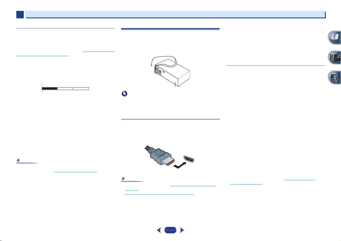
Make sure not to bend the cables over the top of this unit (as
shown in the illustration). If this happens, the magnetic field
produced by the transformers in this unit may cause a
humming noise from the speakers.
•
Before making or changing connections, switch off the
power and disconnect the power cord from the AC outlet.
•
Before unplugging the power cord, switch the power into
standby.
HDMI cables
Both video and sound signals can be transmitted
simultaneously with one cable. If connecting the player and
the TV via this receiver, for both connections, use HDMI
cables.
Be careful to connect the terminal in the proper direction.
•
Set the HDMI parameter in Setting the Audio options on
page 37 to THRU (THROUGH) and set the input signal in
Selecting the audio input signal
on page 25 to HDMI, if you
want to hear HDMI audio output from your TV (no sound
will be heard from this receiver).
•
If the video signal does not appear on your TV, try adjusting
the r esolution s ettings on y our comp onent or display. Note
that some components (such as video game units) have
resolutions that may not be displayed. In this case, use a
(analog) composite connection.
•
When the video signal from the HDMI is 480i, 480p, 576i or
576p, Multi Ch PCM sound and HD sound cannot be
received.
About HDMI
The HDMI connection transfers uncompressed digital video,
as well as almost every kind of digital audio that the
connected component is compatible with, including DVD-
Video, DVD-Audio, SACD, Dolby Digital Plus, Dolby TrueHD,
DTS-HD Master Audio (see below for limitations), Video CD/
Super VCD and CD.
This receiver incorporates High-Definition Multimedia
Interface (HDMI
®
) technology.
This receiver supports the functions described below through
HDMI connections.
•
Digital transfer of uncompressed video (contents protected
by HDCP (1080p/24, 1080p/60, etc.))
•
3D signal transfer
•
Deep Color signal transfer
•
x.v.Color signal transfer
•
Audio Return Channel
•
Input of multi-channel linear PCM digital audio signals
(192 kHz or less) for up to 8 channels
•
Input of the following digital audio formats:
– Dolby Digital, Dolby Digital Plus, DTS, High bitrate audio
(Dolby TrueHD, DTS-HD Master Audio), DVD-Audio, CD,
SACD (DSD 2 ch only), Video CD, Super VCD
•
Synchronized operation with components using the
Control with HDMI function (see Control with HDMI
function on page 53)
SPEAKERS DIMMER DISPLAY
HDMI

Connecting your equipment
2
2
15
•
Use a High Speed HDMI
®
cable. If HDMI cable other than
a High Speed HDMI
®
cable is used, it may not work
properly.
•
When an HDMI cable with a built-in equalizer is connected,
it may not operate properly.
•
3D, Deep Color, x.v.Color signal transfer and Audio Return
Channel are only possible when connected to a compatible
component.
•
HDMI format digital audio transmissions require a longer
time to be recognized. Due to this, interruption in the audio
may occur when switching between audio formats or
beginning playback.
•
Turning on/off the device connected to this unit’s HDMI
OUT terminal during playback, or disconnecting/
connecting the HDMI cable during playback, may cause
noise or interrupted audio.
The terms HDMI and HDMI High-Definition Multimedia
Interface, and the HDMI Logo are trademarks or registered
trademarks of HDMI Licensing LLC in the United States and
other countries.
“x.v.Color” and are trademarks of Sony
Corporation.
Analog audio cables
Use stereo RCA phono cables to connect analog audio
components. These cables are typically red and white, and
you should connect the red plugs to R (right) terminals and
white plugs to L (left) terminals.
Digital audio cables
Commercially available coaxial digital audio cables or optical
cables should be used to connect digital components to this
receiver.
•
When connecting optical cables, be careful when inserting
the plug not to damage the shutter protecting the optical
socket.
•
When storing optical cable, coil loosely. The cable may be
damaged if bent around sharp corners.
•
You can also use a standard RCA video cable for coaxial
digital connections.
Video cables
Standard RCA video cables
These cables are the most common type of video connection
and are used to connect to the composite video terminals. The
yellow plugs distinguish them from cables for audio.
Component video cables (VSX-827 only)
Use component video cables to get the best possible color
reproduction of your video source. The color signal of the TV is
divided into the luminance (Y) signal and the color (P
B and PR)
signals and then output. In this way, interference between the
signals is avoided.
L
R
AUDIO
COAXIAL
IN
OPTICAL
IN
Coaxial digital
audio cable
Optical cable
VIDEO
Y
P
B
P
R
COMPONENT VIDEO
Green (Y)
Red (PR)
Blue (PB)
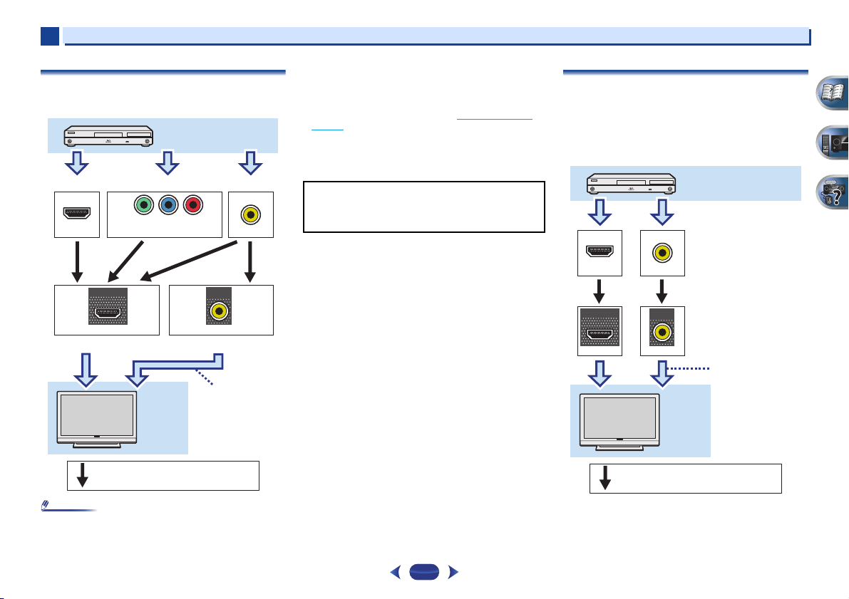
Connecting your equipment
2
2
16
About the video converter (VSX-827 only)
The video converter ensures that all video sources are output
from the HDMI OUT terminal.
•
If several video components are assigned to the same input
function, the converter gives priority to HDMI, component,
then composite (in that order).
•
If the video signal does not appear on your TV, try adjusting
the resolution settings on your component or display. Note
that some components (such as video game units) have
resolutions that may not be converted. In this case, try
switching Video Converter OFF (see Video Converter
on
page 50).
•
The signal input resolutions that can be converted from the
component video input for the HDMI output are 480i/576i,
480p/576p, 720p and 1080i. 1080p signal cannot be
converted.
About video outputs connection
(VSX-527 only)
This receiver is not loaded with a video converter. When you
use HDMI cables for connecting to the input device, the same
cables should be used for connecting to the TV.
The signals input from the analog (composite) video inputs of
this unit will not be output from the HDMI OUT terminal.
VIDEO
IN
IN
HDMI
VIDEO
MONITOR
OUT
HDMI
OUT
IN
COMPONENT VIDEO
YP
B
P
R
Terminal for connection with source device
Terminal for connection with TV monitor
Playback component
TV
Video signals can be output.
The OSD will
not appear.
This item incorporates copy protection technology that is
protected by U.S. patents and other intellectual property
rights of Rovi Corporation. Reverse engineering and
disassembly are prohibited.
VIDEO
VIDEO
IN
IN
HDMI
MONITOR
OUT
HDMI
OUT
Terminal for connection with
source device
Terminal for connection
with TV monitor
Playback component
TV
The OSD will
not appear.
Video signals can be output.
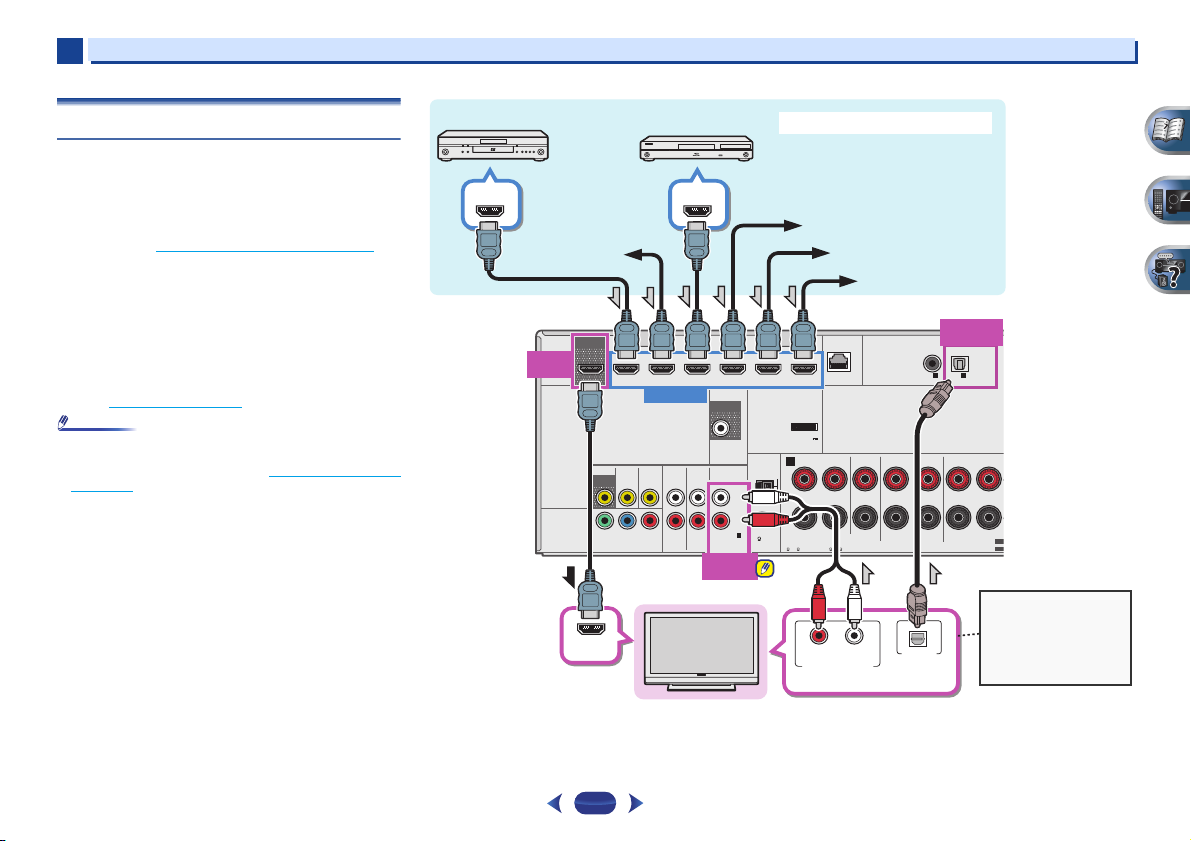
Connecting your equipment
2
2
17
Connecting a TV and playback components
Connecting using HDMI
If you have an HDMI or DVI (with HDCP) equipped component
(Blu-ray Disc player, etc.), you can connect it to this receiver
using a commercially available HDMI cable.
If the TV and playback components support the Control with
HDMI feature, the convenient Control with HDMI functions
can be used (see Control with HDMI function
on page 53).
•
The following connection/setting is required to listen to the
sound of the TV over this receiver.
—
If the TV does not support the HDMI Audio Return
Channel function, connect the receiver and TV with audio
cables (as shown).
—
If the TV supports the HDMI Audio Return Channel
function, the sound of the TV can be input to the receiver
via the HDMI terminal, so there is no need to connect an
audio cable. In this case, set ARC at HDMI Setup to ON
(see HDMI Setup
on page 53).
•
In or der to liste n to the audi o from the TV tha t is connect ed
to this receiver using an analog audio cables, set-up for
analog audio input is required (see The Input Assign menu
on page 50).
HDMI
VIDEO
R
L
AUDIO
COMPONENT VIDEO
PRE OUT
SPEAKERS
ANTENNA
OPTICAL
COAXIAL
LAN
(
10/100
)
DVD
IN
SAT/CBL
IN
MONITOR
OUT
DVD
YP
B
P
R
SAT/CBL
ANALOG IN
IN
IN
DVD GAME VIDEOBD
SAT/CBL DVR/BDR
(
CD
)
(
TV
)
IN
1
IN
1
(
CD
)
OUT
ASSIGNABLE
ASSIGNABLE
ASSIGNABLE
ASSIGNABLE
1
FM UNBAL
75
CAUTION:
ATTENTION:
SPEAKER IMPEDANCE
ENCEINTE D’IMPEDANCE DE
6 -16 .
6 -16 .
AM LOOP
SURROUND
SURROUND BACK
CENTER
FRONT
RLRL
(
Single
)
RL
A
SUB WOOFER
1
IN
(
DVD
)
1
1
(
OUTPUT 5
V
0.1 A MAX
)
ADAPTER PORT
SEL
SEL
HDMI
OUT
ANALOG
IN1 (CD)
HDMI OUT
HDMI IN
DIGITAL AUDIO OUT
OPTICAL
HDMI OUT
HDMI IN
RL
ANALOG AUDIO OUT
OPTICAL
IN1 (TV)
Select one
HDMI/DVI-compatible TV
Set-top box
DVD player
Blu-ray Disc player
Game console
HDMI/DVI-compatible components
If the TV does not support
the HDMI Audio Return
Channel function, this
connection is required to
listen to the TV sound over
the receiver.
DVD recorder,
Blu-ray Disc recorder
Video component
VSX-827
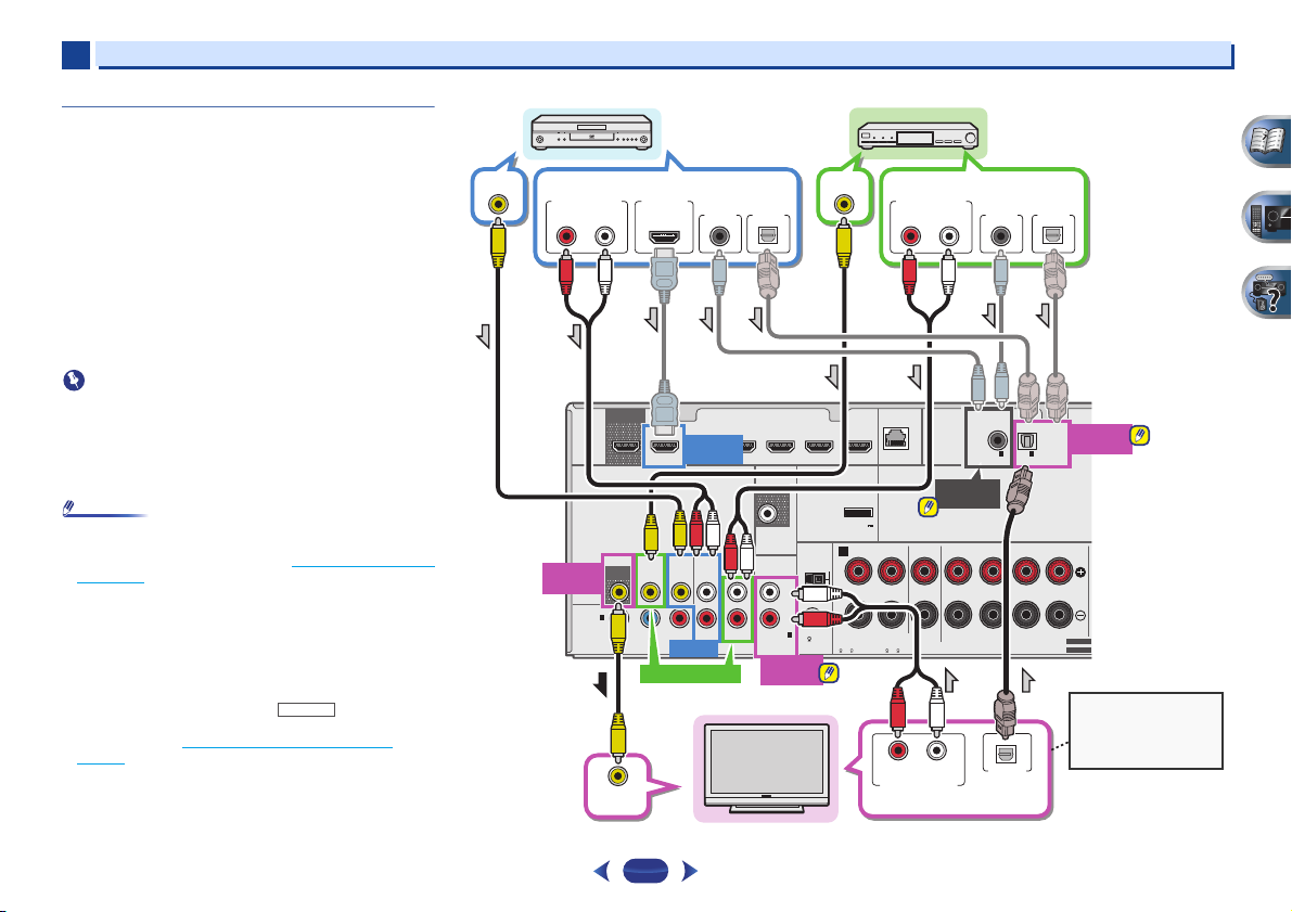
Connecting your equipment
2
2
18
Connecting your TV with no HDMI input
This diagram shows connections of a TV (with no HDMI input)
and DVD player (or other playback component) to the receiver.
•
With these connections, the picture is not output to the TV
even if the DVD player is connected with an HDMI cable.
Connect the DVD player’s video signals using a composite
cable.
•
In order to listening to HD audio with this receiver, connect
an HDMI cable, and use analog video cable for video signal
input.
Depending on the player, it may not be possible to output
video signals to both HDMI and other video output
(composite, etc.) simultaneously, and it may be necessary
to make video output settings. Please refer to the operating
instructions supplied with your player for more information.
•
When the receiver and TV are connected by composite
cable, the OSD function allowing display of the receiver’s
settings, operations, etc., on the TV’s screen cannot be
used. In this case, watch the receiver’s front panel display
while performing the various operations and making
settings.
•
In or der to liste n to the audi o from the TV tha t is connect ed
to this receiver using a analog audio cables, set-up for
analog audio input is required (see The Input Assign menu
on page 50).
•
Only one component can be connected to both the optical
input terminal and coaxial input terminal. If connecting
other devices, please use a different method to connect the
audio.
In order to listen to the audio from the source component
that is connected to this receiver using an optical cable or
a coaxial cable, first, switch to the DVD (DVD player) or
SAT/CBL (set-top box), then use and
SIGNAL
SEL
to choose the audio signal O1 (OPTICAL1) or C1
(COAXIAL1) (see Selecting the audio input signal
on
page 25).
RECEIVER
HDMI
VIDEO
R
L
AUDIO
COMPONENT VIDEO
PRE OUT
SPEAKERS
ANTENNA
OPTICAL
COAXIAL
LAN
(
10/100
)
DVD
IN
SAT/CBL
IN
MONITOR
OUT
DVD
YPB PR
SAT/CBL
ANALOG IN
IN
IN
DVD GAME VIDEOBD
SAT/CBL DVR/BDR
(
CD
)
(
TV
)
IN
1
IN
1
(
CD
)
OUT
ASSIGNABLE
ASSIGNABLE
ASSIGNABLE
ASSIGNABLE
1
FM UNBAL
75
CAUTION:
ATTENTION:
SPEAKER IMPEDANCE
ENCEINTE D’IMPEDANCE DE
6 -16 .
6 -16 .
AM LOOP
SURROUND
SURROUND BACK
CENTER
FRONT
RLRL
(
Single
)
RL
A
SUB WOOFER
1
IN
(
DVD
)
1
1
(
OUTPUT 5
V
0.1 A MAX
)
ADAPTER PORT
SELECTABLE
SELECTABLE
ANALOG
IN1 (CD)
VIDEO IN
DIGITAL AUDIO OUT
OPTICAL
RL
ANALOG AUDIO OUT
OPTICAL
IN1 (TV)
DVD IN
SAT/CBL IN
VIDEO OUT
DIGITAL AUDIO OUT
OPTICALCOAXIAL
RL
ANALOG AUDIO OUT
RL
ANALOG AUDIO OUT
VIDEO OUT
COAXIAL
IN1 (CD)
MONITOR
OUT
HDMI
DVD IN
DIGITAL AUDIO OUT
OPTICALCOAXIAL
HDMI OUT
Select one Select one
Select one
TV
DVD player
Set-top box
This connection is
required in order to listen
to the sound of the TV
over the receiver.
VSX-827
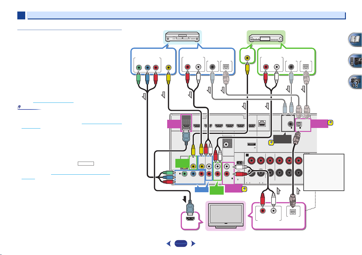
Connecting your equipment
2
2
19
Connecting your DVD player with no HDMI
output (VSX-827 only)
This diagram shows connections of a TV (with HDMI input)
and DVD player (or other playback component with no HDMI
output) to the receiver.
•
The following connection/setting is required to listen to the
sound of the TV over this receiver.
—
If the TV does not support the HDMI Audio Return
Channel function, connect the receiver and TV with audio
cables (as shown).
—
If the TV supports the HDMI Audio Return Channel
function, the sound of the TV can be input to the receiver
via the HDMI terminal, so there is no need to connect an
audio cable. In this case, set ARC at HDMI Setup to ON
(see HDMI Setup
on page 53).
•
In or der to liste n to the audi o from the TV tha t is connect ed
to this receiver using a analog audio cables, set-up for
analog audio input is required (see The Input Assign menu
on page 50).
•
Only one component can be connected to both the optical
input terminal and coaxial input terminal. If connecting
other devices, please use a different method to connect the
audio.
In order to listen to the audio from the source component
that is connected to this receiver using an optical cable or
a coaxial cable, first, switch to the DVD (DVD player) or
SAT/CBL (set-top box), then use and
SIGNAL
SEL
to choose the audio signal O1 (OPTICAL1) or C1
(COAXIAL1) (see Selecting the audio input signal
on
page 25).
RECEIVER
HDMI
VIDEO
R
L
AUDIO
COMPONENT VIDEO
PRE OUT
SPEAKERS
ANTENNA
OPTICAL
COAXIAL
LAN
(
10/100
)
DVD
IN
SAT/CBL
IN
MONITOR
OUT
DVD
YPB PR
SAT/CBL
ANALOG IN
IN
IN
DVD GAME VIDEOBD
SAT/CBL DVR/BDR
(
CD
)
(
TV
)
IN
1
IN
1
(
CD
)
OUT
ASSIGNABLE
ASSIGNABLE
ASSIGNABLE
ASSIGNABLE
1
FM UNBAL
75
CAUTION:
ATTENTION:
SPEAKER IMPEDANCE
ENCEINTE D’IMPEDANCE DE
6 -16 .
6 -16 .
AM LOOP
SURROUND
SURROUND BACK
CENTER
FRONT
RLRL
(
Single
)
RL
A
SUB WOOFER
1
IN
(
DVD
)
1
1
(
OUTPUT 5
V
0.1 A MAX
)
ADAPTER PORT
SELECTABLE
SELECTABLE
COAXIAL
IN1 (CD)
OPTICAL
IN1 (TV)
DVD IN
SAT/CBL
IN
SAT/CBL
IN
VIDEO OUT
DIGITAL AUDIO OUT
OPTICALCOAXIAL
RL
ANALOG AUDIO OUT
RL
ANALOG AUDIO OUT
COMPONENT VIDEO OUT
VIDEO OUT
DIGITAL AUDIO OUT
OPTICALCOAXIAL
HDMI
OUT
HDMI IN
YP
B
P
R
ANALOG
IN1 (CD)
DIGITAL AUDIO OUT
OPTICAL
RL
ANALOG AUDIO OUT
Select one
DVD player
Select one
Select one
Set-top box
If the TV does not
support the HDMI
Audio Return Channel
function, this
connection is required
to listen to the TV
sound over the
receiver.
Select one
HDMI/DVI-compatible TV
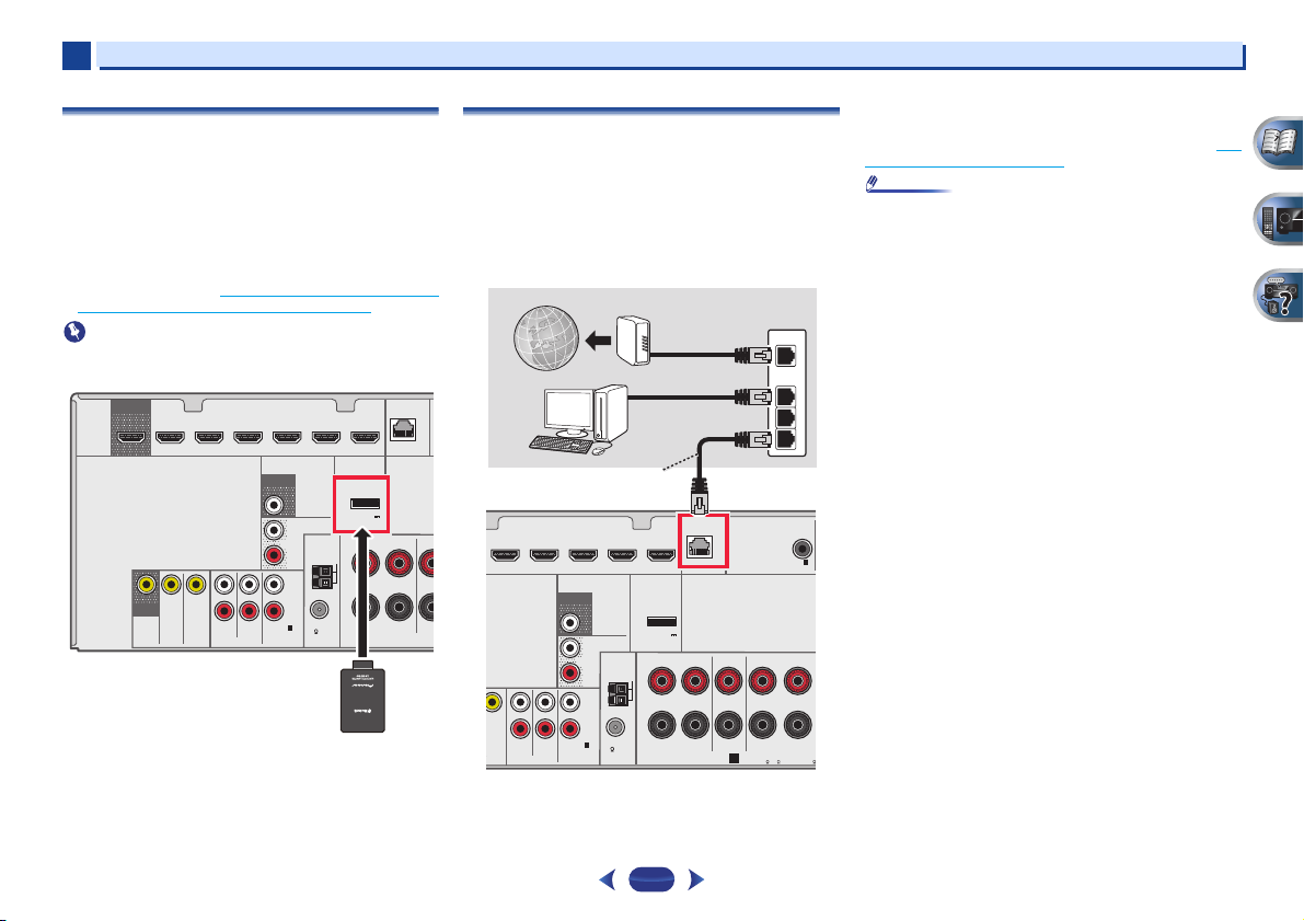
Connecting your equipment
2
2
20
Connecting optional
Bluetooth
®
ADAPTER
When the Bluetooth ADAPTER (Pioneer Model No. AS-BT100
or AS-BT200) is connected to this unit, a product equipped
with Bluetooth wireless technology (portable cell phone,
digital music player, etc.) can be used to listen to music
wirelessly.
Connect a
Bluetooth
ADAPTER to the ADAPTER PORT
terminal on the rear panel.
•
For instructions on playing the Bluetooth wireless
technology device, see Pairing the
Bluetooth ADAPTER and
Bluetooth wireless technology device on page 30.
•
Do not move the receiver with the Bluetooth ADAPTER
connected. Doing so could cause damage or faulty contact.
Connecting to the network through LAN
interface
By connecting this receiver to the network via the LAN
terminal, you can listen to Internet radio stations. To listen to
Internet radio stations, you must sign a contract with an ISP
(Internet Service Provider) beforehand.
When connected in this way, you can play audio files stored
on the components on the local network, including your
computer.
Connect the LAN terminal on this receiver to the LAN terminal
on your router (with or without the built-in DHCP server
function) with a straight LAN cable (CAT 5 or higher).
Turn on the DHCP server f unction of your router. In case you r
router does not have the built-in DHCP server function, it is
necessary to set up the network manually. For details, see The
Network Setup menu on page 41.
•
Refer to the operation manual of the equipment you have as
the connected equipment and connection method may
differ depending on your Internet environment.
•
When using a broadband Internet connection, a contract
with an Internet service provider is required. For more
details, contact your nearest Internet service provider.
HDMI
VIDEO
R
L
AUDIO
PRE OUT
SPEAKERS
ANTENNA
LAN
(
10/100
)
DVD
IN
SAT/CBL
IN
MONITOR
OUT
DVD
SAT/CBL
ANALOG IN
IN
R
L
PRE OUT
SURR BACK/
FRONT HEIGHT
IN
DVD GAME VIDEOBD
SAT/CBL DVR/BDR
(
CD
)
(
Single
)
OUT
ASSIGNABLE
1
FM UNBAL
75
AM LOOP
CE
FRONT
RL
SUB WOOFER
1
(
OUTPUT 5
V
0.1 A MAX
)
ADAPTER PORT
Bluetooth
®
ADAPTER
VSX-527
IDEO
R
L
AUDIO
PRE OUT
SPEAKERS
ANTENNA
COAXIAL
LAN
(
10/100
)
DVD
IN
DVD
SAT/CBL
ANALOG IN
IN
R
L
PRE OUT
SURR BACK/
FRONT HEIGHT
IN
GAME VIDEOBD
SAT/CBL DVR/BDR
(
CD
)
(
Single
)
IN
1
(
CD
)
ASSIGNABLE
ASSIGNABLE
1
FM UNBAL
75
CAUTION:
A
SPEAKER IMPEDANCE
EN
6 -16 .
6
AM LOOP
SURROUND
CENTER
FRONT
RL
RL
A
SUB WOOFER
1
(
OUTPUT 5
V
0.1 A MAX
)
ADAPTER PORT
WAN
3
2
1
LAN
to LAN port
LAN cable
(sold separately)
Router
Modem
Internet
VSX-527
PC
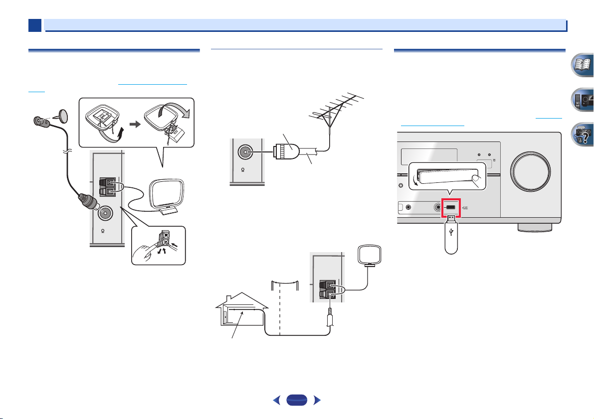
Connecting your equipment
2
2
21
Connecting antennas
Connect the AM loop antenna and the FM wire antenna as
shown below. To improve reception and sound quality,
connect external antennas (see Using external antennas
below).
1
Push open the tabs, then insert one wire fully into each
terminal, then release the tabs to secure the AM antenna
wires.
2
Fix the AM loop antenna to the attached stand.
To fix the stand to the antenna, bend in the direction indicated
by the arrow then clip the loop onto the stand.
3
Place the AM antenna on a flat surface and in a direction
giving the best reception.
4
Connect the FM wire antenna into the FM antenna
socket.
For best results, extend the FM antenna fully and fix to a wall
or door frame. Don’t drape loosely or leave coiled up.
Using external antennas
To improve FM reception
Use a PAL connector (not supplied) to connect an external FM
antenna.
To improve AM reception
Connect a 5 m to 6 m length of vinyl-coated wire to the AM
antenna terminal without disconnecting the supplied AM
loop antenna.
For the best possible reception, suspend horizontally
outdoors.
Connecting a USB device
It is possible to play audio and photo files by connecting USB
devices to this receiver.
Switch the receiver into standby then connect your USB
device to the USB terminal on the front panel of this
receiver.
•
This receiver does not support a USB hub.
•
For instructions on playing the USB device, see Playing a
USB device on page 28.
ANTENNA
FM UNBAL
75
AM LOOP
FM UNBAL
75
75 Ω coaxial cable
One-touch PAL
connector
ANTENNA
AM LOOP
Outdoor
antenna
5 m to 6 m
Indoor antenna
(vinyl-coated wire)
MASTER
VOLUME
iPod iPhone iPad
DIRECT CONTROL
SOUND
RETRIEVER AIR
ADVANCED
SURROUND
MCACC
SETUP
MIC
VIDEO
BAND TUNER EDIT TUNE PRESET ENTER
HDMI
iPod iPhone iPad
iPod
iPhone
iPad
ALC/
STANDARD SURR
O SURROUND
/
EAM DIRECT
USB
CONTROL ON
/
OFF
 Loading…