![]()
PIONEER VSX-322-K RRV4343

Type:  (PDF)
(PDF)
Size
1.9 MB
Page
13
Category
AUDIO
SERVICE MANUAL
If you get stuck in repairing a defective appliance
download
this repair information for help. See below.
Good luck to the repair!
Please do not offer the downloaded file for sell only
use it for personal usage!
Looking for similar pioneer manual?
Document preview [1st page]

Click on the link for free download!
Document preview [2nd page]

Click on the link for free download!
Please tick the box below to get download link:
- Also known:
PIONEER VSX-322K RRV-4343 VSX322K RRV4343 VSX 322 RRV 4343 VSX-322-K
- If you have any question about repairing write your question to the Message board. For this no need registration.
- If the site has helped you and you also want to help others, please Upload a manual, circuit diagram or eeprom that is not yet available on the site.
Have a nice Day! - Please take a look at the below related repair forum topics. May be help you to repair.
Warning!
If you are not familiar with electronics, do not attempt to repair!
You could suffer a fatal electrical shock! Instead, contact your nearest service center!
Note! To open downloaded files you need acrobat reader or similar pdf reader program. In addition,
some files are archived,
so you need WinZip or WinRar to open that files. Also some files are djvu so you need djvu viewer to open them.
These free programs can be found on this page: needed progs
If you use opera you have to disable opera turbo function to download file!
If you cannot download this file, try it with CHROME or FIREFOX browser.
Relevant AUDIO forum topics:
Sziasztok!
Elakadtam ezzel az erősítővel. Eredetileg nem csinált semmit, még egyetlen led sem világított. Mindent átmérve mindent rendben találtam, ha kényszerrel elindítom a tápot készenlétből akkor az összes feszültség rendben van.
Érdekes módon a proci kerámia rezonátora nem rezeg. Egyik lába testen, másik 3.3V-on. Viszont amíg a reset lábat lehúzom testre addig rezeg, és mindkét lába 1.5V körül van.
Észrevettem hogy ha az eepromot leveszem az i2c buszról, akkor 5mp -ig megy a készülék. 2mp után a hangfalvédelmi relék is behúznak, ha a végfok csatlakozót lehúzva indítom akkor overheat -ot ír. Tehát ha hiba lenne azt kiírná és nem kiakadna. Mérve a végfokokon nincs egyenfeszültség. csatlakozókon a protect láb alacsony szintű, ha felhúzom akkor tilt. Tehát 5mp -ig minden rendben.
Viszont ez után a proci leáll, rezonátor nem rezeg, lábai testen és 3.3v-on. Ezután resetre nem indul el csak táp elvételre. Ha addig resetelgetek amíg nem akad ki, akkor újraindulgatva meg hosszú ideig melegedés vagy bármi hiba nélkül.
A másik fura dolog: ha a memóriatartalom az eredeti akkor azonnal kiakad, nincs életjel. Ha csupa FF FF akkor is azonnal kiakad. Ha csupa 00 00 00 -al írom tele akkor egy alkalommal megy a szokásos 5mp -ig, de ezt eltárolja és utána nincs életjel — azonnal kiakad. Mégis mintha súlyos hibát tárolna be…. De miért áll le még a rezonátor is? és még a feszültségek is eltolódnak rajta. És nem indul újra resettel, csak táp elvétellel….
A proci m16c m3030rfgpfp. Valami általános rajzot találtam, de a lábak funkciója itt nem adott — gondolom szoftverfüggő.
Update:
Megnéztem jobban a tanyán lévő szerviz manualt, lehet hogy stimmel de csak a D-main van meg a rajzon. Ez a panel az extra szolgáltatásokért felel, netrádió, lan port, HDMI bemenetek stb. Ha ezt a panelt be sem szerelem akkor is működik az analóg bemenetekkel, mert az előlapi gombok, kijelző, végfok,és tápegység vezérlése mind az alsó panelen lévő processzor (m16c m3030rfgpfp) feladata. Nos ez a proci a hibás — szerintem.
Lehetne a hiba oka hogy a D-mainnal nem tud rendesen kommunikálni de ez nem magyarázná a rezonátor leállását.
Ha valakinek ötlete vagy javaslata volna, kérem segítsen egy kicsit.
Köszi!
Joco
Sziasztok.
Van egy Pioneer F-55L Hi-Fi tuner. A problemat roviden leirnam. Minden ado a frekvenciajara hangolva szepen szol, viszont csak monoban. Sem a «Tuned» sem a «Stereo» led nem gyul ki. Viszont a radiot felfele hangolva 0.15 MHz-et, mar a Tuned es a Stereo Led is kijelez, viszont sercegve szol mar az ado. A radio AN7470 sztereo dekoder IC-t hasznal.
Valakinek van valami otlete? Esetleg kapcsolasi rajz?
Koszonom.
Endre
Sziasztok!
A fenti erősítő kapcsolási rajzára lenne szükségem. Kérem, ha valakinek megvan, küldje el! Vagy ha tudja valaki, hogy hol található, írja meg, mert nekem eddig nem sikerült találnom.
Előre is köszönöm!
Imre
Similar manuals:
If you want to join us and get
repairing help
please sign in or sign up by completing a simple electrical test
or write your question to the Message board without registration.
You can write in English language into the forum (not only in Hungarian)!
E-Waste Reduce
Раздел 2:
a. Такое размещение возможно, только когда к устройству подключен дополнительный усилитель, а
02
02
к усилителю подключены тыловые громкоговорители. Подробнее, см. Подключите задние
Подключение оборудования
громкоговорители объемного звучания
на стр. 11.
Советы по расположению громкоговорителей
Размещение громкоговорителей
Pасположение громкоговорителей в комнате имеет большое влияние на качество звука. Следующие
Подключив левый и правый громкоговорители (
L
/
R
), центральный громкоговоритель (
C
), левый и
рекомендации помогут добиться оптимального звучания вашей системы.
правый громкоговорители объемного звучания (
SL
/
SR
), и низкочастотный громкоговоритель (
SW
),
• Сабвуфер можно поместить на полу. В идеальном случае другие громкоговорители во
можно прослушивать 5.1-канальную систему объемного звучания.
время прослушивания должны располагаться на уровне ушей. Расположение
Кроме того, с помощью внешнего усилителя можно подключить левый и правый задние
громкоговорителей на полу (кроме сабвуфера) или закрепление их высоко на стене не
громкоговорители объемного звучания (SBL/SBR) для повышения системы до 7.1-канальной
рекомендуется.
системы объемного звучания.
• Для получения оптимального стереоэффекта расположите фронтальные громкоговорители
• Можно также подключить один задний громкоговоритель объемного звучания (SB) и
на расстоянии 2–3 метров друг от друга и на равном удалении от телевизора.
прослушивать 6.1-канальную систему объемного звучания.
• В случае расположени
я громкоговорителей около ЭЛ
Т—телевизора, используйте
Для получения наилучшего качества объемного звучания установите громкоговорители, как показано
громкоговорители магнитозащищенного типа или располагайте громкоговорители на
ниже.
достаточном расстоянии от ЭЛТ—телевизора.
• Если используется центральный громкоговоритель, разместите передние
громкоговорители под большим углом. Если нет – под меньшим углом.
• Расположите центральный громкоговоритель под телевизором или над ним, чтобы звук
центрального канала исходил от эк
рана телевизора. Кроме
того, центральный
громкоговоритель не должен пересекать линию, образованную передним краем правого и
левого фронтальных громкоговорителей.
• Лучше всего поверните громкоговорители в направлении точки прослушивания. Угол
зависит от размера помещения. Для более просторных помещений используйте меньший
угол.
• Объемные и задние громкоговорители объемного звучания следует устанавливать на 60–
90 см вы
ше уровня ушей и слегка наклонить вниз. Убедитесь в том, что громкоговорители
не напр
авлены навстречу друг другу. Для формата DVD-Audio громкоговорители должны
находиться дальше от слушателя.
• Если громкоговорители объемного звучания не могут устанавливаться прямо сбоку от
места слушателя при использовании 7.1-канальной системы, эффект объемного звучания
можно усилить, отключив функцию Up Mix (см. Настройка фун
кции Up Mix на стр. 23).
• Старайтесь не размещать громкоговорители объемного
звучания дальше от слушателя, чем
передние и центральные. В противном случае может произойти ослабление эффекта
объемного звучания.
10
Ru
ОСТОРОЖНО
• Все громкоговорители должны быть надежно установлены. Это не только улучшает
качество звука, но и уменьшает риск повреждения или травмы в результате падения или
переворачивания громкоговорителей в случае внешнего толчка (например, при
землетрясении).
Внимание
• Для подключения громкоговорителей объемного звучания требуется дополнительный
усилитель. Подключите дополнительный усилитель к выходам
SURR BACK PRE OUT
данного устройства и подключите тыловые громкоговорители к дополнительному
усилителю (см. Подключите задние громкоговорители объемного звучания на стр. 11).
R
R
L
L
C
C
SW
120
SW
120
120
120
SR
SR
SB
SL
SL
R
L
C
90
SR
SW
90
SBR
SL
60
SBL
Акустическая система 5.1:
Акустическая система 6.1:
a
Акустическая система 7.1:
a
02
02
Подключение громкоговорителей
Ресивер может работать с двумя стерео громкоговорителями (передние громкоговорители на
рисунке), тем не менее, рекомендуется использовать по крайней мере три, а полный комплект
обеспечивает наилучшее объемное звучание.
Убедитесь, что правый громкоговоритель подключен к правому (R) разъему, а левый
громкоговоритель – к левому (L) разъему. Также убедитесь, что положительный и отрицательный (+/
–) разъемы ресивера совпадают с соответствующими разъемами громкоговорителей.
Можно использовать громкоговорители с номинальный импедансом мощностью от 6 Ω до 16 Ω.
Подключайте устройство к сети переменного тока только после завершения всех
соединений.
Подключение проводов
11
Ru
ОСТОРОЖНО
Зажимы передних громкоговорителей:
1 Скрутите оголенные жилы провода.
2 Ослабьте зажим контакта и вставьте
оголенный провод.
3 Зажмите контакт.
Зажимы центрального громкоговорителя и
громкоговорителей объемного звучания:
1 Скрутите оголенные жилы провода.
2 Откройте защитные выступы и
вставьте оголенный провод.
3 Отпустите защитные выступы.
• На контактах громкоговорителей имеется ОПАСНОЕ ДЛЯ ЖИЗНИ напряжение. Во
избежание опасности поражения электрическим током при подключении или отключении
кабелей громкоговорителей отсоединяйте кабель питания, прежде чем прикасаться к
любым неизолированным деталям.
•
Оголенные концы провода громкоговорителя должны быть обязательно скручены и вставлены в
контакт громкоговорителя до конца. Если любой из неизолированных проводов
громкоговорителя коснется задней панели, это может вызвать отключение питания
(срабатывание защиты) в целях безопасности.
Подключите задние громкоговорители объемного звучания
Подключите выходы SURR BACK PRE OUT на устройстве к дополнительному усилителю, чтобы
добавить тыловой громкоговоритель.
• Для одного громкоговорителя можно также подключать дополнительный усилитель к
выходам PRE OUT заднего тылового канала. В этом случае подключайте усилитель только
к левому (
L (Single)) разъему.
12 3
10 мм
12 3
10 мм
LINE LEVEL
INPUT
HDMI
DVR/BDR IN DVD I N BD IN CD/SAT IN
OUT
COAXIAL
OPTICAL
IN
1
IN
1
ASSIGNABLE
(
CD-R / TAPE
)
(
TV
)
AUDIO
CD-R/TAPE SURR BACK
PRE OUT
(
Single
L
)
OUT
R
VIDEO
L
FRONT
IN CD/SAT
ANTENNA
RL
SPEAKERS
A
IN
CD/SAT
R
AM LOOP
CENTER
SURROUND
RL
IN
DVD
L
IN
IN
R
MONITOR
OUT
SUBWOOFER
PRE OUT
TV
DVD
75
FM UNBAL
RL
ANALOG
AUDIO IN
SPEAKER
R
SPEAKER
L
Передний правый
Передний левый
Низкочастотный
Центральный
громкоговоритель
Правый
Левый
объемного
объемного
звучания
звучания
Правый задний
Левый задний
канал
канал
Усилитель заднего канала объемного звучания
02
02
Подсоединение кабелей
Не перегибайте кабели поверх устройства. В противном случае
магнитное поле, генерируемое трансформаторами этого
устройства, может вызвать помехи в громкоговорителях.
12
Ru
Внимание
• Перед выполнением или изменением схем подсоединения
отключите кабель питания от розетки переменного тока.
• Перед отсоединением кабеля питания переключите
питание в режим ожидания.
Кабели HDMI
Одновременно по одному кабелю могут передаваться как видео-,
так и звуковые сигналы. При подключении через этот ресивер
проигрывателя и телевизора, используйте для обоих подключений
кабели HDMI.
Будьте внимательны и соблюдайте правильность направления при
подключении разъема.
Примечание
О HDMI
При помощи подключения HDMI передаются несжатые цифровые
видеосигналы, а также практически любые виды цифрового звука,
с которыми совместим подключенный компонент, включая DVD-
Video, DVD-Audio, Dolby Digital Plus, Dolby TrueHD, DTS-HD
Master Audio (см. ниже информацию об ограничениях), Video CD/
Super VCD и CD.
Данный ресивер поддерживает технологию High-Definition
Multimedia Interface (HDMI
®
).
С помощью подключений HDMI данный ресивер поддерживает
описанные ниже функции.
• Цифровая передача несжатого видео (материала,
защищенного по системе HDCP (1080p/24, 1080p/60, и
др.))
• Передача сигнала 3D
• Передача сигнала Deep Color
• Передача сигнала x.v.Color
• Возвратный аудиоканал
(см. раздел Функция ARC (возвратный аудиоканал) на
стр. 27)
• Прием многоканальных линейных цифровых
аудиосигналов PCM (192 кГц или менее) для макс. 8
каналов
• Прием следующих цифровых аудиоформатов:
– Dolby Digital, Dolby Digital Plus, DTS, аудиосигналы с
высоким битрейтом (Dolby TrueHD, DTS-HD Master
Audio), DVD-Audio, CD, Video CD, Super VCD
• Установите для параметра HDMI в Настройка
параметров звука на стр. 23 значение
THRU (THROUGH)
и задайте для входного сигнала в Выбор входного
аудиосигнала на стр. 17 значение
HDMI, если вы хотите
получить выход звука по HDMI на телевизоре (не будет
слышен звук от этого ресивера).
• Если на телевизоре не появляется видеосигнал,
попробуйте отрегулировать настройки разрешения
используемого компонента или дисплея. Учтите, что
некоторые компоненты (например, игровые
видеоприставки) имеют разрешение, отображение
которого невозможно. В этом случае используйте
(аналоговое) композитное подключение.
• Ког
да через HDMI поступает видеосигнал 480i, 480p, 576i
или 576p, прием мног
оканального звука PCM и HD-звука
невозможен.
Примечание
• Используйте высокоскоростной кабель HDMI. Если
используется обычный кабель HDMI, а не
высокоскоростной кабель HDMI, он может работать
некорректно.
• Если подключается кабель HDMI со встроенным
эквалайзером, он может работать некорректно.
• Передача сигналов 3D, Deep Color, x.v.Color и
возвратного аудиоканала возможна только при
подключении к совместимому аудио—видео компоненту.
• Передачи цифровых аудиосигналов в формате HDMI
требуют большего времени для распознавания. По этой
пр
ичине мож
ет происходить прерывание звучания во
время переключения аудиоформатов или при запуске
воспроизведения.
• Включение/отключение устройства, подключенного к
разъему HDMI OUT этого устройства во время
воспроизведения, или отсоединение/подсоединение
кабеля HDMI во время воспроизведения, может вызвать
HDMI
помехи или прерывание звука.
Термины HDMI и HDMI High-Definition Multimedia Interface,
а также логотип HDMI являются торговыми марками или
зарегистрированными торговыми марками HDMI Licensing,
LLC в С
оединенных
Штатах Америки и в других странах.
“x.v.Color” и являются торговыми
марками Sony Corporation.
Аналоговые аудиокабели
02
02
Для подключения аналоговых аудиокомпонентов используйте
стереофонические аудиокабели RCA. Эти кабели имеют
стандартную красную и белую маркировку, и необходимо
подключить красные штекеры к разъемам R (правый), а белые – к
разъемам L (левый).
Цифровые аудиокабели
Для подключения к данному ресиверу цифровых компонентов
следует использовать имеющиеся в продаже коаксиальные
цифровые аудиокабели или оптические кабели.
13
Ru
Примечание
Видеокабели
Подключение видеовыходов
Данный ресивер не оборудован видеопреобразователем. Если для
Стандартные видеокабели RCA
подключения к входному устройству используются кабели HDMI,
Эти кабели являются наиболее распространенным типом
такие же кабели нужно использовать для подключения к
видеокабелей и используются для подключения к разъемам
телевизору.
композитного видео. Штекеры с желтой маркировкой отличают их
Сигналы, поступающие с аналоговых (композитных) видеовходов
от аудиокабелей.
устройства не будут передаваться с HDMI OUT.
L
AUDIO
R
• Аккуратно выполняйте подключение оптического кабеля,
старайтесь не повредить защитную шторку оптического
разъема.
• Обеспечьте для оптического кабеля свободно свисающую
петлю. Можно повредить кабель об острые углы.
• Для коаксиального цифрового подключения также можно
использовать стандартный видеокабель RCA.
Белый (левый)
Красный (правый)
Коаксиальный
цифровой
аудиокабель
Оптический кабель
VIDEO
Желтый
IN
IN
HDMI
VIDEO
OUT
MONITOR
OUT
HDMI
VIDEO
Компонент
воспроизведения
Терминал для подключения с исходным устройством
Терминал для подключения с телевизионным монитором
Телевизор
Возможность вывода видеосигнала.
02
02
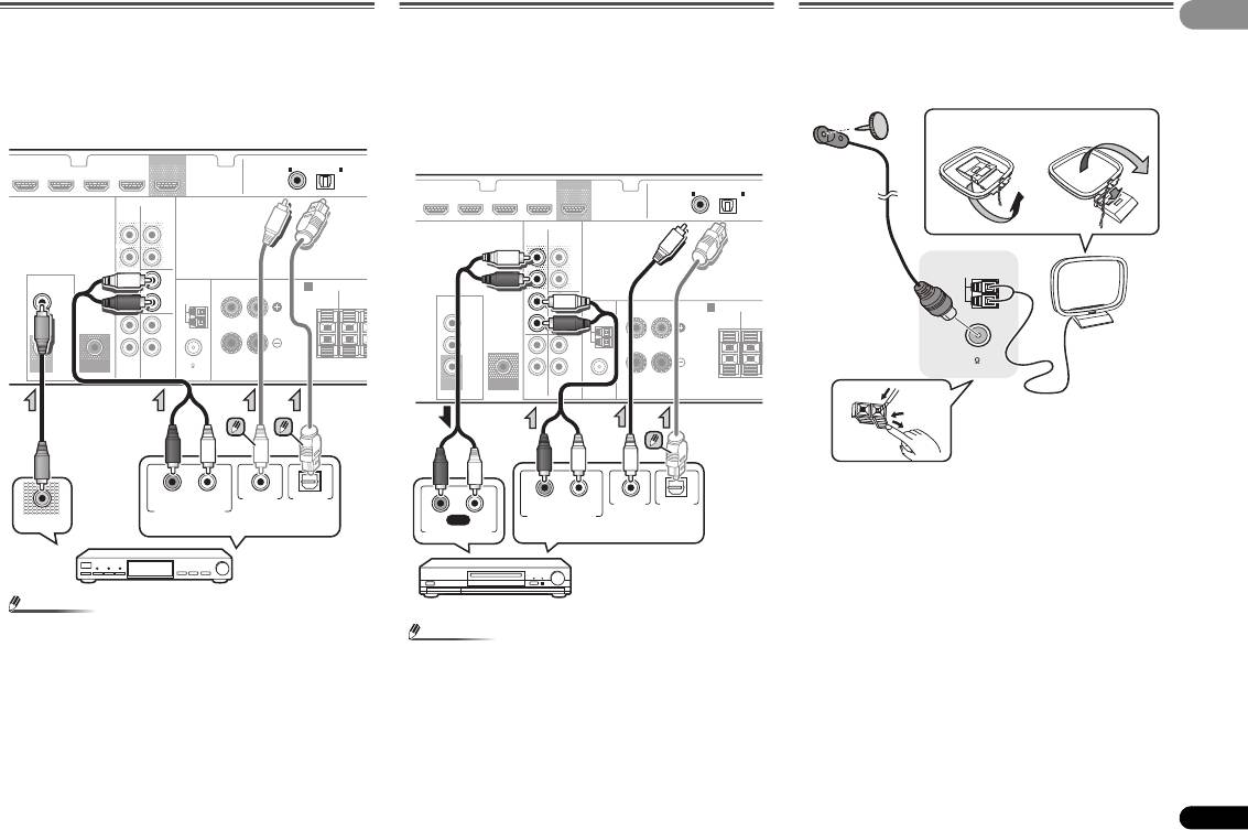
Подключение телевизора и компонентов воспроизведения
Подключение компонента без разъема HDMI
На данном рисунке показаны подключения телевизора и проигрывателя DVD (или другого
компонента воспроизведения) без разъема HDMI к ресиверу.
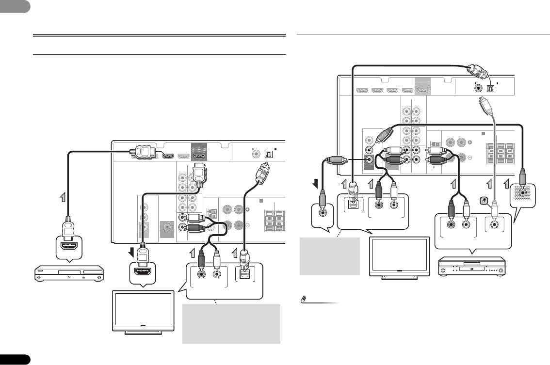
Подключение с помощью HDMI
При наличии устройства с интерфейсом HDMI или DVI (с HDCP) (проигрыватель Blu-ray Disc, и др.),
его можно подключить к данному ресиверу с помощью имеющегося в продаже кабеля HDMI.
• Следующее подключение/настройка требуется для прослушивания звучания телевизора
через ресивер.
—
Если телевизор не поддерживает функцию возвратного аудиоканала через HDMI, подключите
ресивер и телевизор через аудиокабели (как показано).
—
Если телевизор поддерживает функцию возвратного аудиоканала через HDMI, звук с телевизора
вводится в ресивер через терминал HDMI, поэтому нет необходимости подсоединять
аудиокабель. В таком случае, установите параметр ARC в HDMI SET на ON (см. ARC
настройка
на стр. 27).
14
Ru
Примечание
• Для прослушивания аудио с проигрывателя DVD, подключенного к этому ресиверу с
помощью коаксиального кабеля, прежде всего, переключитесь на вход
DVD, затем
нажмите кнопку
SIGNAL SEL, чтобы выбрать аудиосигнал C1 (КОАКСИАЛЬНЫЙ 1) (см.
Выбор входного аудиосигнала на стр. 17).
HDMI
DVR/BDR IN DVD IN BD IN CD/SAT IN
OUT
COAXIAL
OPTICAL
IN
1
IN
1
ASSIG
(
CD-R / TAPE
)
(
TV
)
AUDIO
CD-R/TAPE SURR BACK
PRE OUT
(
Single
L
)
OUT
R
VIDEO
L
FRONT
IN CD/SAT
ANTENNA
RL
SPEAKERS
A
IN
CD/SAT
R
AM LOOP
CENTER
SURRO
R
IN
DVD
L
IN
IN
R
MONITOR
OUT
SUBWOOFER
PRE OUT
TV
DVD
FM UNBAL
75
HDMI OUT
HDMI IN
RL
OPTICAL
DIGITAL AUDIO OUTANALOG AUDIO OUT
Совместимый с HDMI/
DVI проигрыватель
Выберите один
Blu-ray Disc
Если телевизор не поддерживает
функцию возвратного аудиоканала
Телевизор, совместимый
через HDMI, данное подключение
с HDMI/DVI
требуется для прослушивания
звучания телевизора через ресивер.
HDMI
DVR/BDR IN DVD IN BD IN CD/SAT IN
OUT
COAXIAL
OPTICAL
IN
1
IN
1
ASSIGNABLE
(
CD-R / TAPE
)
(
TV
)
AUDIO
CD-R/TAPE SURR BACK
PRE OUT
(
Single
L
)
OUT
R
VIDEO
L
FRONT
IN CD/SAT
SPEAKERS
A
IN
ANTENNA
RL
CD/SAT
R
AM LOOP
CENTER
SURROUND
RL
IN
DVD
L
IN
IN
R
MONITOR
OUT
SUBWOOFER
PRE OUT
TV
DVD
75
FM UNBAL
VIDEO OUT
OPTICAL
RL
DIGITAL AUDIO OUT ANALOG AUDIO OUT
VIDEO IN
RL
COAXIAL
DIGITAL AUDIO OUTANALOG AUDIO OUT
Выберите один
Данное подключение
Выберите один
требуется для
прослушивания звука
телевизора через
ресивер.
Телевизор
Проигрыватель DVD
02
02
Подключение спутникового ресивера или
другой цифровой приставки
Спутниковые и кабельные ресиверы, а также цифровые радио
ресиверы являются примерами так называемых «приставок».
• Если приставка или видеокомпонент также имеют выход
HDMI, его тоже можно подключить. Подробнее см.
раздел Подключение с помощью HDMI на стр. 14.
15
Ru
Примечание
Подключение других аудиокомпонентов
Количество и тип соединений зависит от типа подключаемого
компонента. Для подключения проигрывателей CD-R, MD, DAT,
кассетного магнитофона или других аудиокомпонентов
выполняйте действия, описанные ниже.
• Учтите, что необходимо подключить цифровые
компоненты к гнездам аналогового аудио, если требуется
выполнить запись с цифровых компонентов (например,
минидиска) на аналоговые компоненты или наоборот.
• Для прослушивания аудио с компонента—источника,
подключенного с помощью коаксиального или
оптического кабеля, прежде всего, переключитесь на
CD/
SAT, затем нажмите на кнопку SIGNAL SEL, чтобы
выбрать аудиосигнал
C1 (КОАКСИАЛЬНЫЙ 1) или O1
(ОПТИЧЕСКИЙ 1) (см. Выбор входного аудиосигнала на
стр. 17).
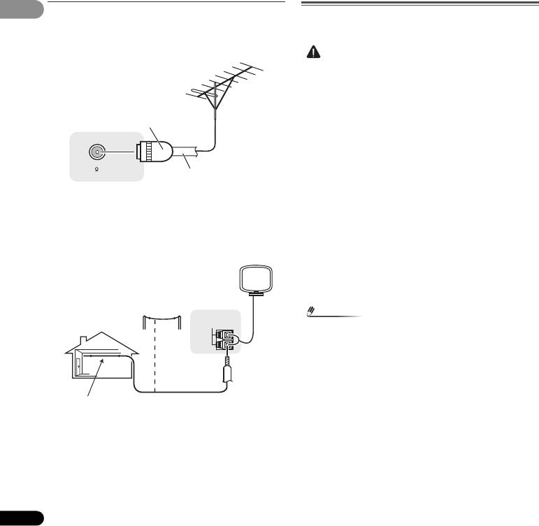
Примечание
Подключение антенн
Подключите рамочную антенну АМ и проволочную антенну FM,
как показано ниже. Для улучшения приема и качества звука
подключите внешние антенны (см. раздел Использование
внешних антенн
на стр. 16).
1 Откройте защитные выступы, вставьте по одному
проводу в каждый разъем до конца, затем отпустите
выступы для фиксации проводов антенны AM.
2 Прикрепите рамочную антенну AM к специальной
стойке.
Чтобы прикрепить антенну к стойке, отогните стойку в
направлении стрелки (рис. а), затем закрепите рамочную антенну
на стойке с помощью зажима (рис. б).
3 Установите антенну AM на плоскую поверхность в
направлении наилучшего приема.
• Для прослушивания аудио с проигрывателя CD,
подключенного к этому ресиверу с помощью оптического
4 Подключите проволочную антенну FM к разъему
кабеля, прежде всего, переключитесь на вход
CD-R, затем
антенны FM.
нажмите кнопку
SIGNAL SEL, чтобы выбрать
Чтобы улучшить прием, полностью вытяните проволочную
антенну FM и прикрепите ее к стене или дверной раме. Не
аудиосигнал
O1 (ОПТИЧЕСКИЙ 1) (см. Выбор входного
допускайте, чтобы антенна свешивалась или спутывалась.
аудиосигнала на стр. 17).
DVR/BDR IN DVD IN BD IN CD/SAT IN
OUT
COAXIAL
OPTICAL
IN
1
IN
1
ASSIGN
(
CD-R / TAPE
)
(
TV
)
AUDIO
CD-R/TAPE SURR BACK
PRE OUT
(
Single
L
)
OUT
R
VIDEO
L
FRONT
IN CD/SAT
A
IN
ANTENNA
RL
SPEAKERS
CD/SAT
R
AM LOOP
CENTER
SURROUN
R
IN
DVD
L
IN
IN
R
MONITOR
OUT
SUBWOOFER
PRE OUT
TV
DVD
FM UNBAL
75
RL
OPTICALCOAXIAL
DIGITAL AUDIO OUTANALOG AUDIO OUT
VIDEO OUT
Выберите один
Приставка, и т.д.
DVR/BDR IN DVD IN BD IN CD/SAT IN
OUT
COAXIAL
OPTICAL
IN
1
IN
1
ASS
(
CD-R / TAPE
)
(
TV
)
AUDIO
CD-R/TAPE SURR BACK
PRE OUT
(
Single
L
)
OUT
R
VIDEO
L
FRONT
IN CD/SAT
A
IN
ANTENNA
RL
SPEAKERS
CD/SAT
R
AM LOOP
CENTER
SURRO
R
IN
DVD
L
IN
IN
R
MONITOR
OUT
SUBWOOFER
PRE OUT
TV
DVD
FM UNBAL
75
RL
OPTICALCOAXIAL
RL
REC
DIGITAL AUDIO OUTANALOG AUDIO OUT
ANALOG AUDIO IN
Выберите один
CD-R, MD, DAT, кассетный
магнитофон, и т.д.
2
ANTENNA
AM LOOP
4
3
FM UNBAL
75
1
02
02
Использование внешних антенн
Подключение ресивера к электророзетке
Включайте вилку в сеть только после подключения к ресиверу
Улучшение качества приема FM
всех устройств (включая громкоговорители).
Для подключения внешней FM-антенны используйте PAL-
соединитель (приобретается отдельно).
Улучшение качества приема AM
Подсоедините провод в виниловой изоляции длиной от 5 м дo 6 м
к гнезду AM антенны, не отсоединяя прилагаемую рамочную
антенну AM.
Для наилучшего качества приема подвесьте ее горизонтально на
улице.
16
Ru
ОСТОРОЖНО
• Держите кабель питания за вилку. Вынимая вилку из
электророзетки, никогда не тяните за сам кабель, никогда
не дотрагивайтесь до кабеля питания влажными руками,
так как это может стать причиной короткого замыкания и
поражения электрическим током. Не ставьте на кабель
питания устройство, мебель или другие предметы и не
зажимайте его каким—либо ины
м образом. Запрещается
завяз
ывать узлы на кабеле питания или связывать его с
другими кабелями. Кабели питания следует прокладывать
в таких местах, где возможность наступить на них будет
маловероятной. Поврежденный кабель питания может
стать причиной возгорания или поражения электрическим
током. Периодически проверяйте кабель питания. Если
кабель питания поврежден, обратитесь за сменным
кабел
ем в ближайший
уполномоченный независимый
сервис—центр Pioneer.
• Используйте только кабель питания, входящий в
комплект поставки данного устройства.
• Используйте прилагаемый кабель питания только по его
прямому назначению, как описано ниже.
• Когда ресивер не используется (например, во время
отпуска), его следует отключать от питания, вынув вилку
из розетки электросети.
Примечание
ANTENNA
FM UNBAL
75
• После подключения данного ресивера к розетке
переменного тока, запускается процесс инициализации
HDMI, занимающий от 2 до 10 секунд. Во время данного
процесса, любые операции недоступны. Во время данного
процесса, на дисплее передней панели мигает индикатор
HDMI, и данный ресивер можно использовать только
после остановки мигания. Данный процесс можно
пропустить, установив функцию
ARC с настройки HDMI
на
OFF (ВЫКЛ). Подробнее, см. Функция ARC
(возвратный аудиоканал) на стр. 27.
1 Вставьте разъем кабеля питания, входящего в
комплект поставки, в гнездо
AC IN
на задней панели
ресивера.
2 Вилку кабеля питания вставьте в розетку
электросети.
Одноконтактный
разьем PAL
Коаксиальный кабель с
сопротивлением 75 Ω
ANTENNA
AM LOOP
Наружная
антенна
Комнатная антенна
от 5 м до 6 м
(с виниловой
изоляцией)
user manualPioneer VSX-322

AV Receiver
Operating Instructions
Discover the benefits of registering your product online at http://www.pioneer.co.uk (or http://www.pioneer.eu).
View the manual for the Pioneer VSX-322 here, for free. This manual comes under the category receivers and has been rated by 19 people with an average of a 8.3. This manual is available in the following languages: English. Do you have a question about the Pioneer VSX-322 or do you need help? Ask your question here
- Contents
- Checking what’s in the box
- Installing the receiver
- Controls and displays
- Connecting your equipment
- Basic playback
- Listening to your system
- The System Setup menu
- ARC (Audio Return Channel) function
- Additional information

Audio
| Power output per channel (20-20KHz@8 Ohm) | — W |
| Audio output channels | 5.1 channels |
| Power output per channel (1KHz@6 Ohm) | 100 W |
| Total Harmonic Distortion (THD) | 0.7 % |
| Output impedance | 6 Ω |
| Audio D/A Converter (DAC) | 24-bit/192kHz |
| Audio A/D Converter (ADC) | 24-bit/96kHz |
| Pre-out connectivity | Yes |
| Pre-out channels | 2 SW |
| Receiver type | Surround |
Inputs
| HDMI in | 4 |
| Composite video in | 2 |
| Digital audio optical in | 1 |
| Digital audio coaxial in | 1 |
| AC (power) in | Yes |
Outputs
| Number of HDMI outputs | 1 |
| Composite video out | 1 |
| Headphone outputs | 1 |
Ports & interfaces
| Speakers connectivity type | Binding post |
| Connectivity technology | Wired |
Network
Radio
| Supported radio bands | AM, FM |
| Radio Data System (RDS) | Yes |
| Preset stations quantity | 30 |
Optical drive
Technical details
| Display | — |
| Audio decoders | Dolby Digital, Dolby Digital EX, Dolby Digital Plus, Dolby Pro Logic II, Dolby Pro Logic IIx, Dolby TrueHD, DTS, DTS 96/24, DTS Neo:6, DTS-ES, DTS-HD Master Audio |
| Remote control included | Yes |
| Product colour | Black |
| Volume control | Rotary |
| On Screen Display (OSD) | Yes |
| Apple docking compatibility | Not supported |
| x.v.Color support | Yes |
| Deep colour support | Yes |
| AirPlay | No |
Power
| AC input voltage | 220-230 V |
| AC input frequency | 50 — 60 Hz |
| Power consumption (typical) | 180 W |
| Power consumption (standby) | 0.45 W |
Weight & dimensions
| Width | 435 mm |
| Depth | 362.5 mm |
| Height | 168 mm |
| Weight | 7600 g |
Packaging content
| Cables included | AC |
| Manual | Yes |
| Warranty card | Yes |
Storage
Video
show more
Can’t find the answer to your question in the manual? You may find the answer to your question in the FAQs about the Pioneer VSX-322 below.
When is my volume too loud?
A volume above 80 decibels can be harmful to hearing. When the volume exceeds 120 decibels, direct damage can even occur. The chance of hearing damage depends on the listening frequency and duration.
Can bluetooth devices of different brands be connected to each other?
Yes, bluetooth is a universal method that allows different devices equipped with bluetooth to connect to each other.
What is bluetooth?
Bluetooth is a way of exchanging data wirelessly between electronic devices via radio waves. The distance between the two devices that exchange data can in most cases be no more than ten metres.
What is HDMI?
HDMI stands for High-Definition Multimedia Interface. An HDMI cable is used to transport audio and video signals between devices.
How can I best clean my receiver?
A slightly damp cleaning cloth or soft, dust-free cloth works best to remove fingerprints. Dust in hard-to-reach places is best removed with compressed air.
Wat is Dolby Atmos?
Dolby Atmos is a technology that ensures that the sound is reflected from the ceiling to where you are listening. This makes it possible to create a 5.1 effect with only 1 speaker.
What is the weight of the Pioneer VSX-322?
The Pioneer VSX-322 has a weight of 7600 g.
What is the height of the Pioneer VSX-322?
The Pioneer VSX-322 has a height of 168 mm.
What is the width of the Pioneer VSX-322?
The Pioneer VSX-322 has a width of 435 mm.
What is the depth of the Pioneer VSX-322?
The Pioneer VSX-322 has a depth of 362.5 mm.
Is the manual of the Pioneer VSX-322 available in English?
Yes, the manual of the Pioneer VSX-322 is available in English .
Is your question not listed? Ask your question here
- Manuals
- Brands
- Pioneer Manuals
- Stereo Receiver
- VSX-322-K
- Operating instructions manual
-
Contents
-
Table of Contents
-
Troubleshooting
-
Bookmarks
Quick Links
VSX-322
-K
AV Receiver
http://www.pioneer.co.uk
(or http://www.pioneer.eu).
Discover the benefits of registering your product online at
Operating Instructions
Related Manuals for Pioneer VSX-322-K
Summary of Contents for Pioneer VSX-322-K
-
Page 1
VSX-322 AV Receiver http://www.pioneer.co.uk (or http://www.pioneer.eu). Discover the benefits of registering your product online at Operating Instructions… -
Page 2
IMPORTANT This product is for general household purposes. Any failure due to use for other than household purposes CAUTION (such as long-term use for business purposes in a restaurant or use in a car or ship) and which requires RISK OF ELECTRIC SHOCK repair will be charged for even during the warranty DO NOT OPEN period. -
Page 3
If the AC plug of this unit does not match the AC Information for users on collection and disposal of old equipment and used batteries outlet you want to use, the plug must be removed Symbol for These symbols on the products, packaging, and/or accompanying documents mean and appropriate one fitted. -
Page 4: Table Of Contents
Thank you for buying this Pioneer product. Please read through these operating instructions so you will know how to operate your model properly. After you have finished reading the instructions, put them away in a safe place for future reference.
-
Page 5: Before You Start
Before you start Flow of settings on the The FL Demo Mode menu (page 26) (When you don’t want the demo display to show on the receiver front panel display.) Checking what’s in the box The unit is a full-fledged AV receiver equipped with an Using the Audio Return Channel function (page 27) abundance of functions and terminals.
-
Page 6: Controls And Displays
Controls and displays Chapter 1: Controls and displays Front panel VSX-322 AV RECEIVER HDMI SPEAKERS DIMMER DISPLAY BAND TUNER EDIT TUNE PRESET ENTER AUTO SURROUND/ ALC/ ADVANCED SOUND STREAM DIRECT STANDARD SURR SURROUND STEREO RETRIEVER INPUT MASTER SELECTOR VOLUME STANDBY / ON PHONES TUNER EDIT –…
-
Page 7: Display
Controls and displays 96/24 – Lights when a source with DTS 96/24 encoded 11 SOUND RETRIEVER Press to restore CD quality sound to compressed audio audio signals is detected. sources (page 22). NEO:6 – When one of the NEO:6 modes of the receiver is on, this lights to indicate NEO:6 processing (page 21).
-
Page 8: Remote Control
Use to select the input source to this receiver (page 17). This MENU Press TUNER first to access: will enable you to control other Pioneer components with the MENU remote control. TUNER EDIT – Memorizes stations for recall (page 18), also used to change the name (page 19).
-
Page 9: Loading The Batteries
12 SOURCE Insert the plus and minus sides of the batteries properly Turns on or off the power of the Pioneer DVD/DVR units when according to the marks in the battery case. BD, DVD, DVR/BDR or CD is selected using the input Batteries with the same shape may have different function buttons.
-
Page 10: Connecting Your Equipment
Connecting your equipment Chapter 2: a. This layout is available only when the additional amplifier is connected to the unit and the surround back speakers are connected to the amplifier. For details, see Connect the surround back Connecting your equipment speakers on page 11.
-
Page 11: Connecting The Speakers
Connecting your equipment Front right Front left Connecting the speakers Subwoofer Center The receiver will work with just two stereo speakers (the front speakers in the diagram) but using at least three speakers is recommended, and a complete setup is best for surround LINE LEVEL INPUT sound.
-
Page 12: Making Cable Connections
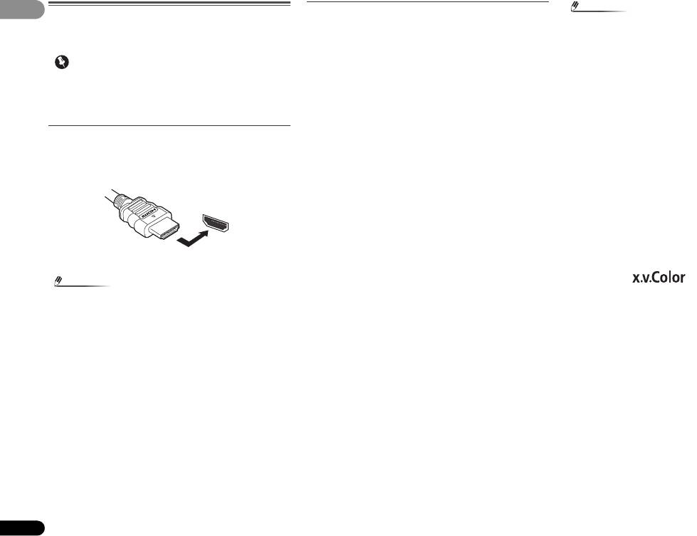
Connecting your equipment Note About HDMI Making cable connections ® • Use a High Speed HDMI cable. If HDMI cable other than The HDMI connection transfers uncompressed digital video, Make sure not to bend the cables over the top of this unit. If ®…
-
Page 13: Analog Audio Cables
Connecting your equipment Analog audio cables Video cables About video outputs connection Use stereo RCA phono cables to connect analog audio This receiver is not loaded with a video converter. When you Standard RCA video cables components. These cables are typically red and white, and use HDMI cables for connecting to the input device, the These cables are the most common type of video connection you should connect the red plugs to R (right) terminals and…
-
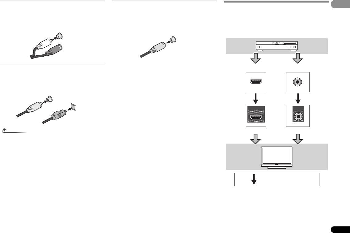
Page 14: Connecting A Tv And Playback Components
Connecting your equipment Connecting your component with no HDMI terminal Connecting a TV and playback components This diagram shows connections of a TV and DVD player (or other playback component) with no HDMI terminal to the receiver. Connecting using HDMI If you have an HDMI or DVI (with HDCP) equipped component (Blu-ray Disc player, etc.), you can connect it to this receiver using a commercially available HDMI cable.
-
Page 15: Connecting A Satellite Receiver Or Other Digital Set-Top Box
Connecting your equipment Connecting a satellite receiver or other digital Connecting other audio components Connecting antennas set-top box The number and kind of connections depends on the kind of Connect the AM loop antenna and the FM wire antenna as component you’re connecting.
-
Page 16: Using External Antennas
Check the power cord once in a while. If you find it FM UNBAL damaged, ask your nearest Pioneer authorized 75 Ω coaxial cable independent service company for a replacement.
-
Page 17: Basic Playback
Basic playback Chapter 3: • The input source can also be selected by using INPUT Selecting the audio input signal buttons on the remote control, or by Basic playback SELECT The audio input signal can be selected for each input source. using the front panel INPUT SELECTOR dial.
-
Page 18: Listening To The Radio
Basic playback • When digital input (optical or coaxial) is selected, this • You may get digital noise when a LD or CD player Listening to the radio receiver can only play back Dolby Digital, PCM (32 kHz to compatible with DTS is playing an analog signal. To 96 kHz) and DTS (including DTS 96 kHz/24 bit) digital prevent noise, make the proper digital connections The following steps show you how to tune in to FM and AM…
-
Page 19: Saving Station Presets
Basic playback Saving station presets Listening to station presets An introduction to RDS If you often listen to a particular radio station, it’s convenient You will need to have some presets stored to do this. See Radio Data System (RDS) is a system used by most FM radio to have the receiver store the frequency for easy recall Saving station presets above if you haven’t done this already.
-
Page 20: Searching For Rds Programs
Basic playback Displaying RDS information AUDIO TUNER EDIT MASTER PARAMETER VOLUME TOOLS MENU Use the DISP button to display the different types of RDS RECEIVER RECEIVER SLEEP SOURCE CONTROL SLEEP SOURCE CONTROL MENU information available. RECEIVER INPUT SELECT DTV/TV RECEIVER INPUT SELECT DTV/TV ENTER…
-
Page 21: Listening To Your System
Listening to your system Chapter 4: Note Surround Listening to your system Type of surround • Stereo surround (matrix) formats are decoded Suitable sources back modes accordingly using NEO:6 CINEMA or DOLBY PLIIx speaker(s) MOVIE (see Listening in surround sound below for more Movie –…
-
Page 22: Using The Advanced Surround
Listening to your system Better sound using Phase Control Using Stream Direct ADVANCED AUTO SURROUND/ Using the Advanced surround BD MENU AUTO/ SURROUND STREAM DIRECT ADV SURR DIRECT This receiver’s Phase Control feature uses phase correction The Advanced surround feature creates a variety of surround Use the Stream Direct modes when you want to hear the measures to make sure your sound source arrives at the effects.
-
Page 23: Using Surround Back Channel Processing
Listening to your system Using surround back channel processing Setting the Up Mix function Setting the Audio options You can have the receiver automatically use 6.1 or 7.1 In a 7.1-channel surround system with surround speakers There are a number of additional sound settings you can decoding for 6.1 encoded sources (for example, Dolby Digital placed directly at the sides of the listening position, the make using the AUDIO PARAMETER menu.
-
Page 24
Listening to your system Setting/What it does Option(s) Setting/What it does Option(s) Setting/What it does Option(s) LFE ATT (LFE Attenuate) 0 (0 dB) 0 to 10 S.RTV (Sound Retriever) C.IMG (Center Image) Default: 3 Some Dolby Digital and DTS audio sources When audio data is removed during the (Applicable only when using a center speaker) 5 (–5 dB) -
Page 25: The System Setup Menu
The System Setup menu Chapter 5: • APD – Sets to automatically turn off the power when the • SB (Surround Back) – Select the number of surround receiver has not operated for several hours (see The Auto back speakers you have (one (X1), two (X2) or none). The System Setup menu Power Down menu on page 26).
-
Page 26: X.over
The System Setup menu 5 Use / to adjust the level of each channel. X.Over The Auto Power Down menu If you selected T. TONE M, use / to switch speakers. The • Default setting: 100Hz T. TONE A setup outputs test tones in the following order Set to automatically turn off the receiver after a specified time (depends on speaker settings): This setting decides the cutoff between bass sounds playing…
-
Page 27: Arc (Audio Return Channel) Function
ARC (Audio Return Channel) function Chapter 6: Before starting ARC operation ARC Setup ARC (Audio Return When starting ARC operation, put the TV and this unit in 1 Press RECEIVER to switch the receiver on. STANDBY mode after connecting this unit with the TV. Next, Channel) function turn ON the power of this unit and then the TV, in this order.
-
Page 28: Additional Information
Broadcast stations cannot be selected automatically. No image is output when an input function is selected. ask your nearest Pioneer authorized independent service Connect an outdoor antenna (refer to page 16). Make sure the component is connected correctly (refer to company to carry out repair work.
-
Page 29: Hdmi
Additional information HDMI Important information regarding the HDMI Resetting the main unit connection Use this procedure to reset all the receiver’s settings to the No picture or sound. If the problem still persists when connecting your HDMI There are cases where you may not be able to route HDMI factory default.
-
Page 30: Specifications
Additional information Miscellaneous Specifications Power Requirements ..AC 220 V to 230 V, 50 Hz/60 Hz Power Consumption ……180 W Audio section In standby .
-
Page 31
253 Alexandra Road, #04-01, Singapore 159936 TEL: 65-6472-7555 PIONEER ELECTRONICS AUSTRALIA PTY. LTD. 5 Arco Lane, Heatherton, Victoria, 3202, Australia, TEL: (03) 9586-6300 PIONEER ELECTRONICS DE MEXICO S.A. DE C.V. Blvd.Manuel Avila Camacho 138 10 piso Col.Lomas de Chapultepec, Mexico, D.F. 11000 TEL: 55-9178-4270 K002_B3_En…
![]()
Discover the benefits of registering your product online at http://www.pioneer.co.uk (or http://www.pioneer.eu).
Operating Instructions
IMPORTANT
The lightning flash with arrowhead symbol, within an equilateral triangle, is intended to alert the user to the presence of uninsulated “dangerous voltage” within the product’s enclosure that may be of sufficient magnitude to constitute a risk of electric shock to persons.
CAUTION
RISK OF ELECTRIC SHOCK
DO NOT OPEN
CAUTION:
TO PREVENT THE RISK OF ELECTRIC SHOCK, DO NOT REMOVE COVER (OR BACK). NO USER-SERVICEABLE PARTS INSIDE. REFER SERVICING TO QUALIFIED SERVICE PERSONNEL.
The exclamation point within an equilateral triangle is intended to alert the user to the presence of important operating and maintenance (servicing) instructions in the literature accompanying the appliance.
D3-4-2-1-1_A1_En
WARNING
This equipment is not waterproof. To prevent a fire or shock hazard, do not place any container filled with liquid near this equipment (such as a vase or flower pot) or expose it to dripping, splashing, rain or moisture.
D3-4-2-1-3_A1_En
WARNING
Before plugging in for the first time, read the following section carefully.
The voltage of the available power supply differs according to country or region. Be sure that the power supply voltage of the area where this unit will be used meets the required voltage (e.g., 230 V or 120 V) written on the rear panel.
D3-4-2-1-4*_A1_En
WARNING
To prevent a fire hazard, do not place any naked flame sources (such as a lighted candle) on the equipment.
D3-4-2-1-7a_A1_En
Operating Environment
Operating environment temperature and humidity: +5 °C to +35 °C (+41 °F to +95 °F); less than 85 %RH (cooling vents not blocked)
Do not install this unit in a poorly ventilated area, or in locations exposed to high humidity or direct sunlight (or strong artificial light)
D3-4-2-1-7c*_A1_En
2
This product is for general household purposes. Any failure due to use for other than household purposes (such as long-term use for business purposes in a restaurant or use in a car or ship) and which requires repair will be charged for even during the warranty period.
K041_A1_En
Ankixxx
VENTILATION CAUTION
When installing this unit, make sure to leave space around the unit for ventilation to improve heat radiation (at least 40 cm at top, 20 cm at rear, and 20 cm at each side).
WARNING
Slots and openings in the cabinet are provided for ventilation to ensure reliable operation of the product, and to protect it from overheating. To prevent fire hazard, the openings should never be blocked or covered with items (such as newspapers, table-cloths, curtains) or by operating the equipment on thick carpet or a bed.
D3-4-2-1-7b*_A1_En
En
Information for users on collection and disposal of old equipment and used batteries
|
Symbol for |
These symbols on the products, packaging, and/or accompanying documents mean |
||||||||
|
equipment |
that used electrical and electronic products and batteries should not be mixed with |
||||||||
|
general household waste. |
|||||||||
|
For proper treatment, recovery and recycling of old products and used batteries, |
|||||||||
|
please take them to applicable collection points in accordance with your national |
|||||||||
|
legislation. |
|||||||||
|
By disposing of these products and batteries correctly, you will help to save valuable |
|||||||||
|
Symbol examples |
resources and prevent any potential negative effects on human health and the |
||||||||
|
for batteries |
environment which could otherwise arise from inappropriate waste handling. |
||||||||
|
For more information about collection and recycling of old products and batteries, |
|||||||||
|
please contact your local municipality, your waste disposal service or the point of sale |
|||||||||
|
where you purchased the items. |
|||||||||
|
These symbols are only valid in the European Union. |
|||||||||
|
For countries outside the European Union: |
|||||||||
|
If you wish to discard these items, please contact your local authorities or dealer and |
|||||||||
|
ask for the correct method of disposal. |
Pb
K058a_A1_En
If the AC plug of this unit does not match the AC outlet you want to use, the plug must be removed and appropriate one fitted. Replacement and mounting of an AC plug on the power supply cord of this unit should be performed only by qualified service personnel. If connected to an AC outlet, the cut-off plug can cause severe electrical shock. Make sure it is properly disposed of after removal.
The equipment should be disconnected by removing the mains plug from the wall socket when left unused for a long period of time (for example, when on vacation).
D3-4-2-2-1a_A1_En
CAUTION
The STANDBY/ON switch on this unit will not completely shut off all power from the AC outlet. Since the power cord serves as the main disconnect device for the unit, you will need to unplug it from the AC outlet to shut down all power. Therefore, make sure the unit has been installed so that the power cord can be easily unplugged from the AC outlet in case of an accident. To avoid fire hazard, the power cord should also be unplugged from the AC outlet when left unused for a long period of time (for example, when on vacation).
D3-4-2-2-2a*_A1_En
3
En

Thank you for buying this Pioneer product. Please read through these operating instructions so you will know how to operate your model properly. After you have finished reading the instructions, put them away in a safe place for future reference.
Contents
Before you start . . . . . . . . . . . . . . . . . . . . . . . . . . . . 5
Checking what’s in the box . . . . . . . . . . . . . . . . . . . . . . . . 5 Installing the receiver . . . . . . . . . . . . . . . . . . . . . . . . . . . . 5
Flow of settings on the receiver. . . . . . . . . . . . . . 5
01 Controls and displays
Front panel . . . . . . . . . . . . . . . . . . . . . . . . . . . . . . . . . . . . 6 Display . . . . . . . . . . . . . . . . . . . . . . . . . . . . . . . . . . . . . . 7 Remote control . . . . . . . . . . . . . . . . . . . . . . . . . . . . . . . . . 8 Loading the batteries . . . . . . . . . . . . . . . . . . . . . . . . . . . 9
Operating range of remote control . . . . . . . . . . . . . . . . . 9
02 Connecting your equipment
Placing the speakers. . . . . . . . . . . . . . . . . . . . . . . . . . . . 10
Hints on the speaker placement. . . . . . . . . . . . . . . . . . 10
Connecting the speakers. . . . . . . . . . . . . . . . . . . . . . . . . 11
Connect the surround back speakers. . . . . . . . . . . . . . 11
Making cable connections . . . . . . . . . . . . . . . . . . . . . . . 12 HDMI cables . . . . . . . . . . . . . . . . . . . . . . . . . . . . . . . . 12 About HDMI. . . . . . . . . . . . . . . . . . . . . . . . . . . . . . . . . 12 Analog audio cables. . . . . . . . . . . . . . . . . . . . . . . . . . . 13 Digital audio cables . . . . . . . . . . . . . . . . . . . . . . . . . . . 13 Video cables. . . . . . . . . . . . . . . . . . . . . . . . . . . . . . . . . 13
About video outputs connection . . . . . . . . . . . . . . . . . . . 13 Connecting a TV and playback components . . . . . . . . . . 14
Connecting using HDMI . . . . . . . . . . . . . . . . . . . . . . . 14
Connecting your component with no
HDMI terminal . . . . . . . . . . . . . . . . . . . . . . . . . . . . . . . 14
Connecting a satellite receiver or other digital
set-top box. . . . . . . . . . . . . . . . . . . . . . . . . . . . . . . . . . . . 15
Connecting other audio components . . . . . . . . . . . . . . . 15
Connecting antennas . . . . . . . . . . . . . . . . . . . . . . . . . . . 15 Using external antennas . . . . . . . . . . . . . . . . . . . . . . . 16 Plugging in the receiver . . . . . . . . . . . . . . . . . . . . . . . . . 16
03 Basic playback
Canceling the demo display . . . . . . . . . . . . . . . . . . . . . . 17 Playing a source . . . . . . . . . . . . . . . . . . . . . . . . . . . . . . . 17
Selecting the audio input signal . . . . . . . . . . . . . . . . . 17
Listening to the radio . . . . . . . . . . . . . . . . . . . . . . . . . . . 18 Improving FM sound . . . . . . . . . . . . . . . . . . . . . . . . . . 18 Saving station presets . . . . . . . . . . . . . . . . . . . . . . . . . 19
Listening to station presets . . . . . . . . . . . . . . . . . . . . . 19
Naming preset stations . . . . . . . . . . . . . . . . . . . . . . . . 19 An introduction to RDS . . . . . . . . . . . . . . . . . . . . . . . . . 19
Searching for RDS programs . . . . . . . . . . . . . . . . . . . 20 Displaying RDS information . . . . . . . . . . . . . . . . . . . . 20
Making an audio recording. . . . . . . . . . . . . . . . . . . . . . . 20
04 Listening to your system
Choosing the listening mode . . . . . . . . . . . . . . . . . . . . . 21
Auto playback . . . . . . . . . . . . . . . . . . . . . . . . . . . . . . . 21
Listening in surround sound . . . . . . . . . . . . . . . . . . . . 21 Using the Advanced surround . . . . . . . . . . . . . . . . . . 22
Using Stream Direct . . . . . . . . . . . . . . . . . . . . . . . . . . 22 Using the Sound Retriever . . . . . . . . . . . . . . . . . . . . . . . 22
Better sound using Phase Control . . . . . . . . . . . . . . . . . 22 Using surround back channel processing . . . . . . . . . . . 23
Setting the Up Mix function . . . . . . . . . . . . . . . . . . . . . . 23 Setting the Audio options . . . . . . . . . . . . . . . . . . . . . . . . 23
05 The System Setup menu
Using the System Setup menu . . . . . . . . . . . . . . . . . . . . 25
The Speaker Setup menu . . . . . . . . . . . . . . . . . . . . . . . . 25 Speaker Setting . . . . . . . . . . . . . . . . . . . . . . . . . . . . . . 25 X.Over . . . . . . . . . . . . . . . . . . . . . . . . . . . . . . . . . . . . . 26 Channel Level . . . . . . . . . . . . . . . . . . . . . . . . . . . . . . . 26 Speaker Distance . . . . . . . . . . . . . . . . . . . . . . . . . . . . 26
The Auto Power Down menu . . . . . . . . . . . . . . . . . . . . . 26 The FL Demo Mode menu. . . . . . . . . . . . . . . . . . . . . . . . 26
06 ARC (Audio Return Channel) function
ARC Setup . . . . . . . . . . . . . . . . . . . . . . . . . . . . . . . . . . . 27
Before starting ARC operation . . . . . . . . . . . . . . . . . . 27
07 Additional information
Troubleshooting . . . . . . . . . . . . . . . . . . . . . . . . . . . . . . . 28 General . . . . . . . . . . . . . . . . . . . . . . . . . . . . . . . . . . . . 28 HDMI . . . . . . . . . . . . . . . . . . . . . . . . . . . . . . . . . . . . . 29
Important information regarding the HDMI
connection . . . . . . . . . . . . . . . . . . . . . . . . . . . . . . . . . 29 Resetting the main unit . . . . . . . . . . . . . . . . . . . . . . . . . 29 Cleaning the unit . . . . . . . . . . . . . . . . . . . . . . . . . . . . . . 29 Specifications . . . . . . . . . . . . . . . . . . . . . . . . . . . . . . . . 30
4
En

Before you start
Checking what’s in the box
Please check that you’ve received the following supplied accessories:
•Remote control
•AAA size IEC R03 dry cell batteries (to confirm system operation) x2
•AM loop antenna
•FM wire antenna
•Power cord
•Warranty card
•Quick start guide
•These operating instructions (CD-ROM)
Installing the receiver
•When installing this unit, make sure to put it on a level and stable surface.
Don’t install it on the following places:
–on a color TV (the screen may distort)
–near a cassette deck (or close to a device that gives off a magnetic field). This may interfere with the sound.
–in direct sunlight
–in damp or wet areas
–in extremely hot or cold areas
–in places where there is vibration or other movement
–in places that are very dusty
–in places that have hot fumes or oils (such as a kitchen)
Flow of settings on the receiver
The unit is a full-fledged AV receiver equipped with an abundance of functions and terminals. It can be used easily after following the procedure below to make the connections and settings.
The colors of the steps indicate the following:
Required setting item
Setting to be made as necessary
1 Connecting the speakers
Where you place the speakers will have a big effect on the sound.
•Placing the speakers (page 10)
•Connecting the speakers (page 11)
2 Connecting the components
For surround sound, you’ll want to hook up using a digital connection from the Blu-ray Disc/DVD player to the receiver.
•About video outputs connection (page 13)
•Connecting a TV and playback components (page 14)
•Connecting antennas (page 15)
•Plugging in the receiver (page 16)
3 Power On
Make sure you’ve set the video input on your TV to this receiver. Check the manual that came with the TV if you don’t know how to do this.
4 Specify the size and number of speakers you’ve
connected
• Speaker Setting (page 25)
5The FL Demo Mode menu (page 26)
(When you don’t want the demo display to show on the front panel display.)
Using the Audio Return Channel function (page 27)
(When the connected TV supports the HDMI Audio Return Channel function.)
6Playing a source (page 17)
•Selecting the audio input signal (page 17)
•Choosing the listening mode (page 21)
7Adjusting the sound as desired
•Using the Sound Retriever (page 22)
•Better sound using Phase Control (page 22)
•Using surround back channel processing (page 23)
•Setting the Up Mix function (page 23)
•Setting the Audio options (page 23)
•The Speaker Setup menu (page 25)
5
En

01 Controls and displays
Chapter 1:
Controls and displays
Front panel
|
1 |
2 |
3 |
4 |
5 |
6 |
7 |
||||||||
|
AV RECEIVER VSX-322 |
||||||||||||||
|
HDMI |
12 |
13 |
14 |
15 |
16 |
14 |
17 |
|||||||
|
SPEAKERS |
DIMMER DISPLAY BAND |
TUNER EDIT |
TUNE |
PRESET |
ENTER |
|||||||||
|
AUTO SURROUND/ |
ALC/ |
ADVANCED |
SOUND |
|||||||||||
|
STREAM DIRECT STANDARD SURR |
SURROUND |
STEREO |
RETRIEVER |
|||||||||||
|
INPUT |
MASTER |
|||||||||||||
|
SELECTOR |
VOLUME |
|||||||||||||
|
STANDBY/ON |
||||||||||||||
|
PHONES |
19 |
20 |
21 |
22 |
23 22 |
24 |
||||||||
|
18 |
1 INPUT SELECTOR dial
Selects an input source (page 17).
2Receiver control buttons
SPEAKERS – Use to change the speaker system on or off. When the SP OFF is selected, no sound is output from the speakers connected to this receiver.
DIMMER – Dims or brightens the display. The brightness can be controlled in four steps.
DISPLAY – Switches the display of this unit. The listening mode, sound volume or input name can be checked by selecting an input source.
3Character display
See Display on page 7.
4Tuner control buttons
BAND – Switches between AM, FM ST (stereo) and FM MONO radio bands (page 18).
11
TUNER EDIT – Use with TUNE /, PRESET / and
ENTER to memorize and name stations for recall (page 18).
TUNE / – Used to find radio frequencies (page 18).
PRESET / – Use to select preset radio stations (page 19).
5 Remote sensor
Receives the signals from the remote control (see Operating range of remote control on page 9).
6 HDMI indicator
Blinks when connecting an HDMI-equipped component; lights when the component is connected (page 14).
7MASTER VOLUME dial
8STANDBY/ON
9 PHONES jack
Use to connect headphones. When the headphones are connected, there is no sound output from the speakers. The listening mode when the sound is heard from the headphone can be selected only from PHONES SURR, STEREO or
STEREO ALC mode.
10Listening mode buttons
AUTO SURROUND/STREAM DIRECT – Switches between Auto surround mode (page 21) and Stream Direct playback (page 22).
ALC/STANDARD SURR – Press for standard decoding and to switch between the modes of 2Pro Logic II, 2 Pro Logic IIx and NEO:6, and the Auto level control stereo mode (page 21).
ADVANCED SURROUND – Switches between the various surround modes (page 22).
STEREO – Press to select stereo playback (page 21).
6
En

Controls and displays
11 SOUND RETRIEVER
Press to restore CD quality sound to compressed audio sources (page 22).
Display
12 PHASE
Lights when the Phase Control is switched on (page 22).
13 AUTO
Lights when the Auto Surround feature is switched on (page 21).
14Tuner indicators
RDS – Lights when an RDS broadcast is received (page 19).
ST – Lights when a stereo FM broadcast is being received in auto stereo mode (page 18).
TUNE – Lights when a normal broadcast channel.
PRESET – Shows when a preset radio station is registered or called.
MEM – Blinks when a radio station is registered.
kHz/MHz – Lights when the character display is showing the currently received AM/FM broadcast frequency.
15Speaker indicators
Shows if the speaker system is on or not (page 6). SP A means the speakers are switched on.
SP means the speakers are switched off.
16 Sleep timer indicator
Lights when the receiver is in sleep mode (page 8).
17PRESET information or input signal indicator
Shows the preset number of the tuner or the input signal type, etc.
18Character display
Displays various system information.
19DTS indicators
DTS – Lights when a source with DTS encoded audio signals is detected.
HD – Lights when a source with DTS-EXPRESS or DTSHD encoded audio signals is detected.
ES – Lights to indicate DTS-ES decoding.
01
96/24 – Lights when a source with DTS 96/24 encoded audio signals is detected.
NEO:6 – When one of the NEO:6 modes of the receiver is on, this lights to indicate NEO:6 processing (page 21).
20Dolby Digital indicators
2D – Lights when a Dolby Digital encoded signal is detected.
2D+ – Lights when a source with Dolby Digital Plus encoded audio signals is detected.
2HD – Lights when a source with Dolby TrueHD encoded audio signals is detected.
EX – Lights to indicate Dolby Digital EX decoding.
2PLII(x) – Lights to indicate 2Pro Logic II/2Pro Logic IIx decoding (see Listening in surround sound on page 21 for more on this).
21ADV.S.
Lights when one of the Advanced Surround modes has been selected (see Using the Advanced surround on page 22 for more on this).
22SIGNAL SELECT indicators
DIGITAL – Lights when a digital audio signal is selected. Blinks when a digital audio signal is selected and selected audio input is not provided.
HDMI – Lights when an HDMI signal is selected. Blinks when an HDMI signal is selected and selected HDMI input is not provided.
23Up Mix/DIMMER indicator
Lights when the Up Mix function is set to ON (page 23). Also, lights when DIMMER is set to off.
24 DIR.
Lights when the DIRECT or PURE DIRECT mode is switched on (page 22).
7
En
01 Controls and displays
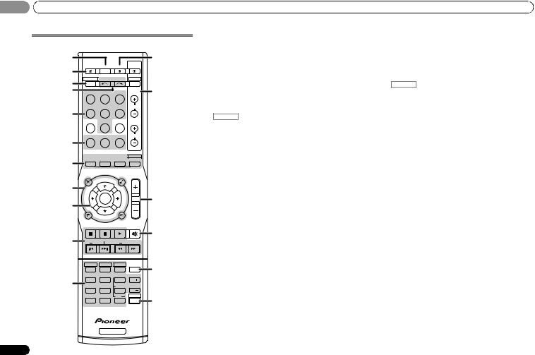
Remote control
|
1 |
12 |
|||
|
RECEIVER SLEEP |
SOURCE |
TV |
||
|
2 |
CONTROL |
|||
|
3 |
RECEIVER |
INPUT SELECT |
DTV/TV |
|
|
INPUT |
||||
|
4 |
BD |
DVD |
TV |
13 |
|
DVR/BDR |
CD |
CD-R |
CH |
|
|
5 |
||||
|
ADAPTER |
TUNER |
PORTABLE |
||
|
PHASE |
S.RETRIEVER |
SIGNAL SEL |
VOL |
|
|
6 |
||||
|
AUTO/ |
ALC/ |
BD MENU |
||
|
7 |
DIRECT |
STEREO |
STANDARD |
ADV SURR |
|
AUDIO |
TUNER EDIT |
MASTER |
|||
|
PARAMETER |
TOOLS |
VOLUME |
|||
|
TOP |
TUNE |
MENU |
|||
|
8 |
MENU |
||||
|
T |
P |
||||
|
E |
R |
14 |
|||
|
S |
ENTER |
E |
|||
|
E |
S |
||||
|
9 |
R |
E |
|||
|
P |
|||||
|
T |
|||||
|
HOME |
|||||
|
MENU |
TUNE |
BAND |
|||
|
SETUP |
RETURN |
||||
|
PTY SEARCH |
MUTE |
||||
|
15 |
|||||
|
10 |
|||||
|
BASS |
TRE |
||||
|
HDD |
DVD |
VCR |
16 |
||
|
1 |
2 |
3 |
DISP |
||
|
TEST TONE |
SB CH |
CH SELECT |
|||
|
11 |
4 |
5 |
6 |
CH |
|
|
MIDNIGHT SPEAKERS |
LEV |
||||
|
7 |
8 |
9 |
CH |
||
|
DIMMER |
0 |
LEV |
SHIFT |
17 |
|
|
CLR |
ENTER |
||||
|
+10 |
|||||
|
RECEIVER |
8
As for operating other devices, the remote control codes for the Pioneer products are preset. The settings cannot be changed.
1 SLEEP
Press to change the amount of time before the receiver switches into standby (30 min – 60 min – 90 min – Off). You can check the remaining sleep time at any time by pressing
SLEEP once.
2 RECEIVER
Switches the receiver between standby and on.
3 RECEIVER
Switches the remote to control the receiver (used to select the white commands above the number buttons (MIDNIGHT, etc)). Also use this button to set up surround sound (page 25) or Audio parameters (page 23).
4 INPUT SELECT 
Use to select the input source (page 17).
5 Input function buttons
Use to select the input source to this receiver (page 17). This will enable you to control other Pioneer components with the remote control.
•ADAPTER, PORTABLE button is not used with this receiver.
6Receiver control buttons
PHASE – Press to switch on/off Phase Control (page 22).
S.RETRIEVER – Press to restore CD quality sound to compressed audio sources (page 22).
SIGNAL SEL – Press to select the audio input signal of the component to play back (page 17).
7Listening mode buttons
AUTO/DIRECT – Switches between Auto surround mode (page 21) and Stream Direct playback (page 22). STEREO – Press to select stereo playback (page 21).
ALC/STANDARD – Press for standard decoding and to switch between the modes of 2Pro Logic II, 2Pro Logic IIx and NEO:6, and the Auto level control stereo mode (page 21).
ADV SURR – Switches between the various surround modes (page 22).
Press BD first to access:
BD MENU* – Displays the disc menu of Blu-ray Discs.
8 System Setup and component control buttons
The following button controls can be accessed after you have selected the corresponding input function button (BD, DVD, etc.).
Press RECEIVER first to access:
AUDIO PARAMETER – Use to access the Audio options (page 23).
SETUP – Press to access the System Setup menu (page 25).
RETURN – Confirm and exit the current menu screen. Press BD, DVD or DVR/BDR first to access:
TOP MENU – Displays the disc ‘top’ menu of a Blu-ray Disc/DVD.
HOME MENU – Displays the HOME MENU screen. RETURN – Confirm and exit the current menu screen. MENU – Displays the TOOLS menu of Blu-ray Disc player.
Press TUNER first to access:
TUNER EDIT – Memorizes stations for recall (page 18), also used to change the name (page 19).
BAND – Switches between AM, FM ST (stereo) and FM MONO radio bands (page 18).
PTY SEARCH – Use to search for RDS program types (page 19).
9 / / / (TUNE /, PRESET /), ENTER
Use the arrow buttons when setting up your surround sound system (page 25). Also used to control Blu-ray Disc/DVD menus/options.
Use TUNE / can be used to find radio frequencies and PRESET / can be used to select preset radio stations (page 19).
10 Component control buttons
The main buttons ( , , etc.) are used to control a component after you have selected it using the input function buttons.
The controls above these buttons can be accessed after you have selected the corresponding input function button (BD, DVD, DVR/BDR and CD). These buttons also function as described below.
En
Press RECEIVER first to access:
BASS –/+, TRE –/+ – Use to adjust Bass or Treble.
•These controls are disabled when the listening mode is set to DIRECT or PURE DIRECT.
•When the front speaker is set at SMALL in the Speaker Setting and the X.OVER is set above 150 Hz, the subwoofer channel level will be adjusted by pressing BASS –/+ (page 26).
11 Number buttons and other component controls
Use the number buttons to directly select a radio frequency (page 18) or the tracks on a CD, etc. There are other buttons that can be accessed after RECEIVER is pressed. (For example MIDNIGHT, etc.)
HDD*, DVD*, VCR* – These buttons switch between the hard disk, DVD and VCR controls for HDD/DVD/VCR recorders.
SB CH – Press to select ON, AUTO or OFF the surround back channel (page 23).
CH SELECT – Press repeatedly to select a channel, then use LEV +/– to adjust the level (page 26).
LEV +/– – Use to adjust the channel level.
MIDNIGHT – Switches to Midnight or Loudness listening (page 23).
SPEAKERS – Use to change the speaker system on or off. When the SP OFF is selected, no sound is output from the speakers connected to this receiver.
DIMMER – Dims or brightens the display. The brightness can be controlled in four steps.
12 SOURCE
Turns on or off the power of the Pioneer DVD/DVR units when BD, DVD, DVR/BDR or CD is selected using the input function buttons.
13 TV CONTROL buttons
These buttons can control only be used with Pioneer TVs.– Use to turn on/off the power of the TV.
INPUT – Use to select the TV input signal. CH +/– – Use to select channels.
VOL +/– – Use to adjust the volume on your TV.
DTV/TV* – Switches between the DTV and analog TV input modes for Pioneer TVs.
14 MASTER VOLUME +/–
Use to set the listening volume.
15 MUTE
Mutes/unmutes the sound.
16 DISP
Switches the display of this unit. The listening mode, sound volume or input name can be checked by selecting an input source.
17 SHIFT
Press to access the ‘boxed’ commands (above the buttons) on the remote. These buttons are marked with an asterisk (*) in this section.
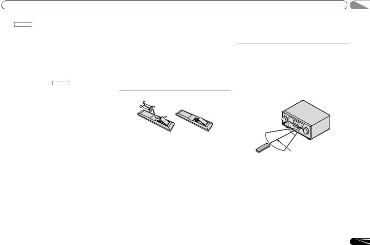
Loading the batteries
The batteries included with the unit are to check initial operations; they may not last over a long period. We recommend using alkaline batteries that have a longer life.
 CAUTION
•Incorrect use of batteries may result in such hazards as leakage and bursting. Observe the following precautions: —Never use new and old batteries together.
—Insert the plus and minus sides of the batteries properly according to the marks in the battery case.
—Batteries with the same shape may have different voltages. Do not use different batteries together.
—When disposing of used batteries, please comply with governmental regulations or environmental public institution’s rules that apply in your country or area.
—Do not use or store batteries in direct sunlight or other excessively hot place, such as inside a car or near a heater. This can cause batteries to leak, overheat, explode or catch fire. It can also reduce the life or performance of batteries.
WARNING
Store the batteries out of the reach of children and infants. If accidentally swallowed, contact a doctor immediately.
Operating range of remote control
The remote control may not work properly if:
•There are obstacles between the remote control and the receiver’s remote sensor.
•Direct sunlight or fluorescent light is shining onto the remote sensor.
•The receiver is located near a device that is emitting infrared rays.
•The receiver is operated simultaneously with another infrared remote control unit.
30°  30°
30° 
7 m
9
En
02 Connecting your equipment
Chapter 2:
Connecting your equipment
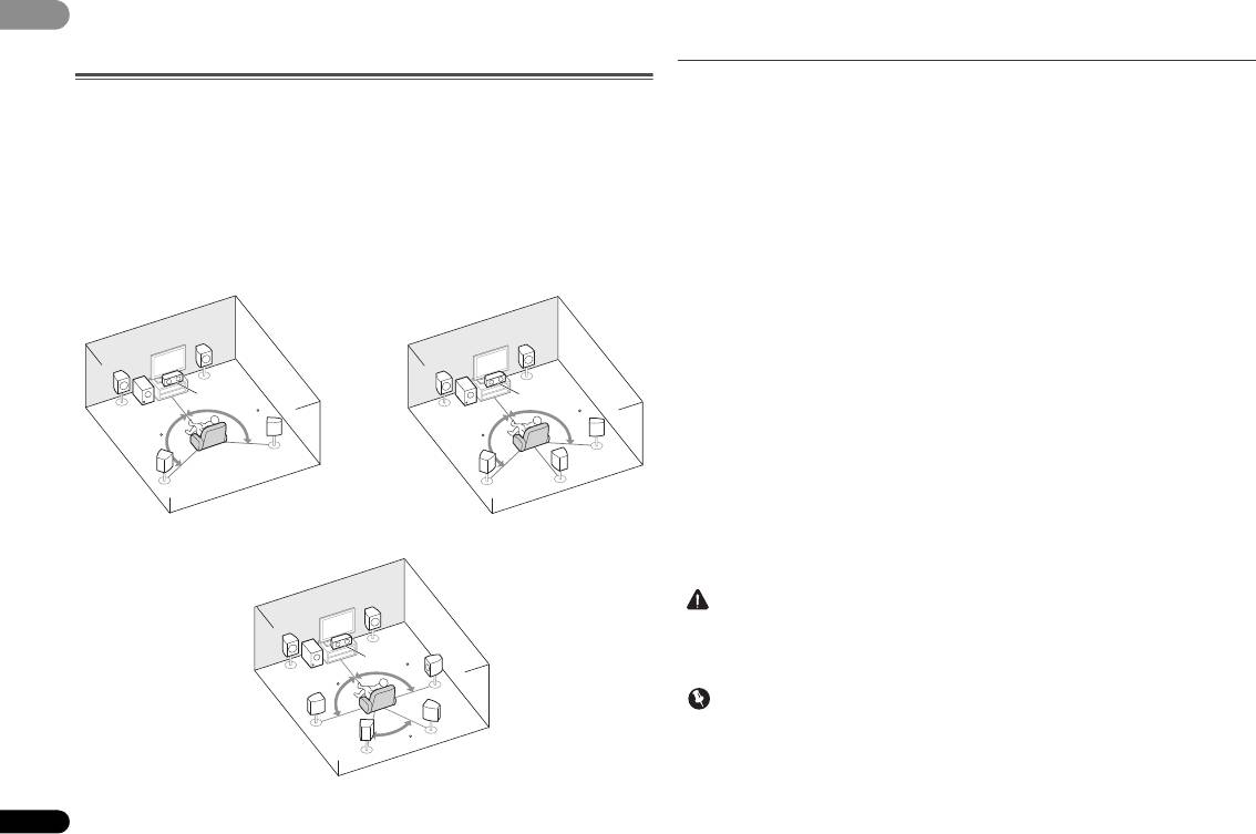
Placing the speakers
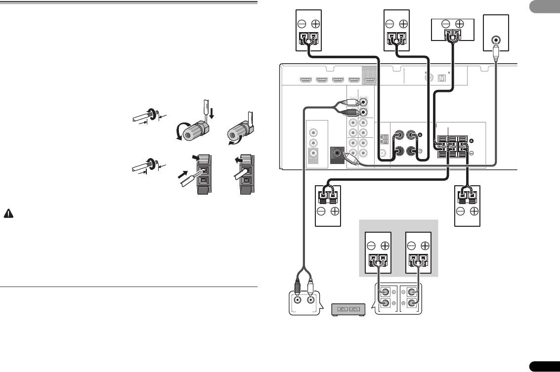
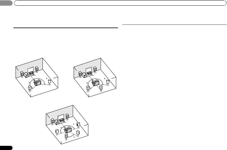
By connecting the left and right front speakers (L/R), the center speaker (C), the left and right surround speakers (SL/SR), and the subwoofer (SW), a 5.1 ch surround system can be enjoyed.
Further, by using an external amplifier, you can connect the left and right surround back speakers (SBL/SBR) to boost your system up to a 7.1 ch surround system.
• You can also connect one surround back speaker (SB) and enjoy a 6.1 ch surround system. To achieve the best possible surround sound, install your speakers as shown below.
|
5.1 channel surround system: |
6.1 channel surround system: a |
|||||
|
R |
R |
|||||
|
L |
L |
|||||
|
C |
C |
|||||
|
SW |
120 |
SW |
120 |
|||
|
120 |
120 |
|||||
|
SR |
SR |
|||||
|
SL |
SL |
SB |
||||
|
7.1 channel surround system: a |
||||||
|
R |
||||||
|
L |
||||||
|
C |
90 |
SR |
||||
|
SW |
||||||
|
90 |
||||||
|
SL |
SBR |
|||||
|
60 |
||||||
|
SBL |
||||||
10
a.This layout is available only when the additional amplifier is connected to the unit and the surround back speakers are connected to the amplifier. For details, see Connect the surround back speakers on page 11.
Hints on the speaker placement
Where you put your speakers in the room has a big effect on the quality of the sound. The following guidelines should help you to get the best sound from your system.
•The subwoofer can be placed on the floor. Ideally, the other speakers should be at about ear-level when you’re listening to them. Putting the speakers on the floor (except the subwoofer), or mounting them very high on a wall is not recommended.
•For the best stereo effect, place the front speakers 2 m to 3 m apart, at equal distance from the TV.
•If you’re going to place speakers around your CRT TV, use shielded speakers or place the speakers at a sufficient distance from your CRT TV.
•If you’re using a center speaker, place the front speakers at a wider angle. If not, place them at a narrower angle.
•Place the center speaker above or below the TV so that the sound of the center channel is localized at the TV screen. Also, make sure the center speaker does not cross the line formed by the leading edge of the front left and right speakers.
•It is best to angle the speakers towards the listening position. The angle depends on the size of the room. Use less of an angle for bigger rooms.
•Surround and surround back speakers should be positioned 60 cm to 90 cm higher than your ears and titled slight downward. Make sure the speakers don’t face each other. For DVD-Audio, the speakers should be more directly behind the listener than for home theater playback.
•If the surround speakers cannot be set directly to the side of the listening position with a 7.1-channel system, the surround effect can be enhanced by turning off the Up Mix function (see Setting the Up Mix function on page 23).
•Try not to place the surround speakers farther away from the listening position than the front and center speakers. Doing so can weaken the surround sound effect.
 CAUTION
•Make sure that all speakers are securely installed. This not only improves sound quality, but also reduces the risk of damage or injury resulting from speakers being knocked over or falling in the event of external shocks such as earthquakes.
 Important
•To connect the surround back speakers, an additional amplifier is required. Connect the additional amplifier to the SURR BACK PRE OUT outputs of this unit and connect the surround back speakers to the additional amplifier (see Connect the surround back speakers on page 11).
En
 Loading…