-
Page 1
Model 2850 Service Manual IMPORTANT: Fill in Pertinent Information on Page 3 for Future Reference… -
Page 2: Table Of Contents
Table of Contents Job Specification Sheet……………………….3 General Commercial Pre-Installation Check List………………..4 3200 Timer Setting Procedure……………………..5 3210 Timer Settings…………………………. 6 3200 & 3210 Timer Series Regeneration Cycle Program Setting Procedure…………7 3200 Timer Assembly……………………….. 8 3200 Timer Assembly Parts List……………………..
-
Page 3: Job Specification Sheet
Job Specification Sheet *Job No. *Model No. *Water Test *Capacity Per Unit *Mineral Tank Size Diameter Height *Brine Tank Size & Salt Setting per Regeneration *2850 Control Valve Specifications 1. Type of Timer A. 7 Day or 12 Day B. *625 to 10,625 Gallon Meter or *3,125 to 53,125 Gallon Meter or *Other C.
-
Page 4: General Commercial Pre-Installation Check List
General Commercial Pre-Installation Check List WATER PRESSURE: A minimum of 25 pounds of water pressure is required for regeneration valve to operate effectively. ELECTRICAL FACILITIES: A continuous 115 volt, 60 Hertz current supply is required. Make certain the current supply is always hot and cannot be turned off with another switch. EXISTING PLUMBING: Condition of existing plumbing should be free from lime and iron buildup.
-
Page 5: 3200 Timer Setting Procedure
3200 Timer Setting Procedure How To Set Days On Which Water Conditioner Is To Regenerate: Rotate the skipper wheel until the number “1” is at the red pointer. Set the days that regeneration is to occur by slid- ing tabs on the skipper wheel outward to expose trip fin- gers.
-
Page 6: 3210 Timer Settings
3210 Timer Settings Typical Programming Procedure How To Manually Regenerate Your Water Condi- tioner At Any Time: Calculate the gallon capacity of the system, subtract the necessary reserve requirement and set the gallons Turn the manual regeneration knob clockwise. available opposite the small white dot on the program This slight movement of the manual regeneration wheel gear.
-
Page 7: 3200 & 3210 Timer Series Regeneration Cycle Program Setting Procedure
3200 & 3210 Timer Series Regeneration Cycle Program Setting Procedure (Brine Tank Refill Separate from Rapid Rinse) How To Set The Regeneration Cycle Program: The regeneration cycle program on your water condi- tioner has been factory preset, however, portions of the cycle or program may be lengthened or shortened in time to suit local conditions.
-
Page 8: 3200 Timer Assembly
3200 Timer Assembly Page 8…
-
Page 9: 3200 Timer Assembly Parts List
3200 Timer Assembly Parts List 1….1….. 13870….Housing, Timer, 3200 2….1….. 13011….Arm, Cycle Actuator 3….1….. 40096-24….Dial 12AM Regen Assy, Black 40096-02….Dial 2AM Regen Assy, Black 4.
-
Page 10: 3210 Timer Assembly
3210 Timer Assembly Page 10…
-
Page 11: 3210 Timer Assembly Parts List
3210 Timer Assembly Parts List Item No. Quantity Part No. Description 1….1….13870-01….Housing Assembly, Timer, 3210 2….1….13802…….Gear, Cycle Actuator 3….1….40096-24….Dial 12AM Regen Assy, Black 40096-02….Dial 2AM Regen Assy, Black 4….1….13886…….Knob, 3200 5.
-
Page 12: Control Valve With 1700 Injector Assembly
Control Valve with 1700 Injector Assembly Page 12…
-
Page 13: Control Valve With 1700 Injector Assembly Parts List
Control Valve with 1700 Injector Assembly Parts List Item No. Quantity Part No. Description 1….1….. 16250…….Valve Body, 2850 16250-01….Valve Body, 2850, Machd 2….6….. 16101…….Seal, 2850 3….5….. 16638…….Spacer, 9500/2850 4….1….. 16092…….Piston, 2850 5.
-
Page 14: Environmental Power Head Assembly
Environmental Power Head Assembly Page 14…
-
Page 15: Environmental Power Head Assembly Parts List
Environmental Power Head Assembly Parts List Item No. Quantity Part No. Description 1…..1….. 18697-15…….. Backplate, Hinged 2……….. 3200 Clock Timer Assy… 3200 Clock Timer Assy 3200 Meter Timer Assy… 3200 Meter Timer Assy 3…..1….. 41543……..Motor, Drive, 115V, 50/60 Hz 41544.
-
Page 16: Control Drive Assembly
Control Drive Assembly Page 16…
-
Page 17: Control Drive Assembly Parts List
Control Drive Assembly Parts List Item No. Quantity Part No. Description 1….1….. 40264…….Backplate, SS/SVO, w/T Screws — 3200 7 Day 2….1…………Timer — 3200 12 Day — 3210 Meter 3….1….. 40084-12….Power Cord, 12’ US, Round, 120V Sys 5, 6, 7 & 2900/3150/3900 #4 4.
-
Page 18: Manual Drive Assembly & Parts List
Manual Drive Assembly & Parts List Item No. Quantity Part No. Description 1….1….. 12593…….Backplate, Manual 2….1….. 12592…….Bracket, Lever Position 3….1….. 12596…….Screw, Spec Mach, 1/4 — 20 x 1/2 4.
-
Page 19: 1600 Brine System Assembly & Parts List
1600 Brine System Assembly & Parts List Item No. Quantity Part No. Description 1….1……10328……Fitting, Elbow, 90 Deg. 1/4 PT x 3/8T 2….1……12767……Screen, Brine 3….2……10332……Fitting, Insert, 3/8 4….
-
Page 20: 1700 Brine System Assembly
1700 Brine System Assembly Page 20…
-
Page 21: 1700 Brine System Assembly Parts List
1700 Brine System Assembly Parts List Item No. Quantity Part No. Description 1….1….. 14792…….Plug, End, Brine Valve 2….1….. 13201…….Quad Ring, -020 3….1….. 12085…….Washer, Flow, 1.2 GPM 12086…….Washer, Flow, 1.5 GPM 12087…….Washer, Flow, 2.0 GPM 12088…….Washer, Flow, 2.4 GPM 12089…….Washer, Flow, 3.0 GPM 12090…….Washer, Flow, 3.5 GPM…
-
Page 22: 1710 Brine System Assembly & Parts List
1710 Brine System Assembly & Parts List Item No. Quantity Part No. Description 1….1….. 41202…….Brine Valve, 1700, Plastic, Top 2….1….. 14785-01….Retainer, Flow Control 3….1….. 14811…….O-Ring, -210, 560CD, Brine 4….1….. 14798…….Spacer, 1700, Brine 5.
-
Page 23: 1600 Service Valve Operator Assembly & Parts List
1600 Service Valve Operator Assembly & Parts List Item No. Quantity Part No. Description 1….1….. 11749…….Guide, Brine Valve Stem 2….1….. 10250…….Ring, Retaining 3….1….. 10249…….Spring, Brine Valve 4….1….. 12550…….Quad Ring, -009 5.
-
Page 24: 2300 Safety Brine Valve Assembly & Parts List
2300 Safety Brine Valve Assembly & Parts List Item No. Quantity Part No. Description 1….1….. 60027-FFA….Safety Brine Valve Body, 2300 Fitting Facing Arm 60027-FFS….Safety Brine Valve Body Fitting Facing Stud 2….1….. 60028-30….Float Assy, 2300, 30”, Blue/White 60026-30SAN..Float Assy, 2350, 30”, HW 3.
-
Page 25: 2310 Safety Brine Valve Assembly & Parts List
2310 Safety Brine Valve Assembly & Parts List Item No. Quantity Part No. Description 1….1….. 60014…….Safety Brine Valve Assy, 2310 2….1….. 60068…….Float Assy, 2310, w/30” Rod ……….60026-30….Float Assy, 2350, 30” Red/Wht 3.
-
Page 26: 2350 Safety Brine Valve Assembly & Parts List
2350 Safety Brine Valve Assembly & Parts List Item No. Quantity Part No. Description 1….1….. 60038…….Safety Brine Valve, 2350 1A….1….. 61024…….Actuator Assy, 2350 Brine 2….1….. 60026-30….Float Assy, 2350, 30” Red/Wht ……….60026-30SAN..Float Assy, 2350, 30”, HW 3.
-
Page 27: 1″ Meter Assembly & Parts List
1” Meter Assembly & Parts List Item No. Quantity Part No. Description 1….1….. 14959…….Body, Meter, 2750 2….1….. 13882…….Post, Meter Impeller 3….1….. 13509…….Impeller, Meter 4….1….. 13847…….O-ring, -137, Std/560CD, Meter 5A….
-
Page 28: 1/2″ Meter Assembly & Parts List
1 1/2” Meter Assembly & Parts List Item No. Quantity Part No. Description 1….1….. 17569…….Body, Meter, 2850/9500 2….1….. 13882…….Post, Meter Impeller 3….1….. 13509…….Impeller, Meter 4….1….. 13847…….O-Ring, -137, Std/560CD, Meter 5A….
-
Page 29
Notes Page 29… -
Page 30: Service Assemblies
Service Assemblies 24 Hour Gear Assemblies 60034-xx… 1700 Brine Valve Assy 19205….Gear Assy, 24 Hour, Silver, 5600, (Specify flow control 1.0 — 5.0) 12 A.M. 60604-xx… Model 1710 Brine Valve Assy 60519-02 Gear Assy, 3200 24 Hour 2 Times/. (Specify flow control 1.0 — 5.0) Day, w/Silver Label 60519-03.
-
Page 31
Service Assemblies 61560-01… Meter Assy, In-Line, w/1” NPT Service Equipment Plstc Connector 16174….Silicone, 2 oz. Tube 61560-07… Meter Assy, In-Line, w/1” NPT 16586-8….. Silicone, Dow #7 8 Lb Brass Connector 16516….Stuffer Assy, 2850/9500 61560-09. -
Page 32: Service Instructions
Service Instructions Problem Cause Correction 1. Water conditioner fails to A. Electrical service to unit has A. Assure permanent electrical service regenerate. been interrupted (check fuse, plug, pull chain, or switch) B. Timer is defective. B. Replace timer. C. Power failure. C.
-
Page 33: General Service Hints For Meter Control
Service Instructions Problem Cause Correction 8. Softener fails to draw brine. A. Drain line flow control is A. Clean drain line flow control. plugged. B. Injector is plugged. B. Clean injector C. Injector screen plugged. C. Clean screen. D. Line pressure is too low. D.
-
Page 34: Water Conditioner Flow Diagrams
Water Conditioner Flow Diagrams 1 Service Position Hard water enters unit at valve inlet and flows down through the mineral in the mineral tank. Conditioned water enters center tube through the bottom distributor, then flows up through the center tube, around the piston, and out the outlet of the valve. 2 Backwash Position 3 Brine Position Hard water enters unit at valve inlet, flows through…
-
Page 35
Water Conditioner Flow Diagrams 4 Slow Rinse Position Hard water enters unit at valve inlet, flows up into injector housing and down through nozzle and throat, around the piston, down through mineral, enters center tube through bottom distributor, flows up through center tube, around piston and out through drain line. 6 Brine Tank Refill Position 5 Rapid Rinse Hard water enters unit at valve inlet, flows directly… -
Page 36: Flow Data & Injector Draw Rates
Flow Data & Injector Draw Rates Page 36…
-
Page 37: System #4 — Typical Single Tank Installation With Optional Meter
System #4 — Typical Single Tank Installation with Optional Meter Page 37…
-
Page 38: System #5 Interlock — Typical Twin Tank Installation With Optional Meter Interlock And No Hard Water Bypass
System #5 Interlock — Typical Twin Tank Installation with Optional Meter Interlock and No Hard Water Bypass Page 38…
-
Page 39: System #6 — Twin Series Regeneration Installatio Nwith A Remote Meter
System #6 — Twin Series Regeneration Installation with a Remote Meter Page 39…
-
Page 40: System #7 — Twin Alternator Installation With A Remote Meter
System #7 — Twin Alternator Installation with a Remote Meter Page 40…
-
Page 41: System #4 — Single Valve Regeneration Immediate And Delayed Valve Wiring
System #4 — Single Valve Regeneration Immediate and Delayed Valve Wiring Page 41…
-
Page 42: System #4 — With Remote Starter Valve Wiring
System #4 — with Remote Starter Valve Wiring Page 42…
-
Page 43: System #5 — Interlocked Regeneration Valve Wiring
System #5 — Interlocked Regeneration Valve Wiring 40502-01_REVB 40502-02_REVB Page 43…
-
Page 44: System #6 — Series Regeneration Valve Wiring
System #6 — Series Regeneration Valve Wiring 13632-01_REVK 13632-02_REVL Page 44…
-
Page 45: System #7 — Alternating Regeneration 230V / 3-Way Solenoid Output Valve Wiring
System #7 — Alternating Regeneration 230V / 3-Way Solenoid Output Valve Wiring 19138-01_REVD 19138-02_REVD Page 45…
-
Page 46: System #7 — Alternating Regeneration 24V / 120V / 3-Way Solenoid Output Valve Wiring
System #7 — Alternating Regeneration 24V / 120V / 3-Way Solenoid Output Valve Wiring 17727-01_REVD 17727-02_REVD Page 46…
-
Page 47
Notes Page 47… -
Page 48
P/N 16510 Rev. F 02/06…
- Manuals
- Brands
- Pentair Manuals
- Control Unit
- FLECK 9100 SXT
- User manual
-
Contents
-
Table of Contents
-
Troubleshooting
-
Bookmarks
Quick Links
Related Manuals for Pentair Fleck 9100 — SXT
Summary of Contents for Pentair Fleck 9100 — SXT
-
Page 1
Fleck 9100 — SXT… -
Page 2: Original Settings
User Guide Fleck 9100-SXT Original settings Installation settings Installation no. Controller type Valve type Valve serial no. Resin type Resin volume [°tH] [°tH] Inlet water hardness Outlet water hardness Tank size Tank capacity °tH] [kg] Brine tank size Salt quantity per regeneration Hydraulic settings Injector size BLFC…
-
Page 3
User Guide Fleck 9100-SXT Maintenance record book Date¹ Description² Name³ Signature⁴ No. FR 1 Date Datum Fecha Data Datum 2 Description Beschreibung Descripción Descrizione Beschrijving 3 Nom Name Nombre Nome Naam 4 Signature Unterschrift Firma Firma Handtekening Ref. MKT-UG-008 / A — 27.10.2016 4 / 28… -
Page 4: Limitation Of Liability
Pentair shall not accept any liability for any loss or damage of profits, revenues, use, production, or contracts, or for any indirect, special or consequential loss or damage whatsoever. Please refer to the Pentair List Price to know more about terms and conditions applicable to this product.
-
Page 5: Technical Specifications
User Guide Fleck 9100-SXT Safety 2.1. Safety tags location MADE IN XXXXXX Model By Pentair International LLC 123456789012345678 Model: Part number P/N: 123456789012345678 For Timer Only Electrical rating 1234567 12345678 1234567 1234567 Serial number : 123456789012345678901234 Serial Note: Ensure that the safety tags on the device are completely legible and clean. If necessary, replace them with new tags and put them in the same places.
-
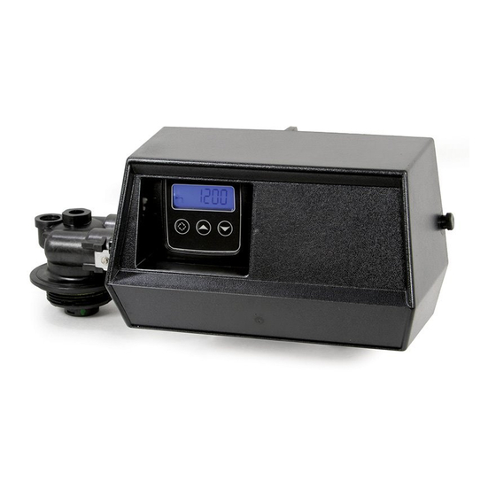
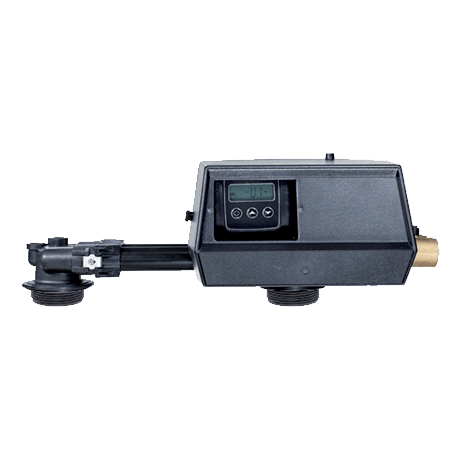
Page 6: Description And Components Location
User Guide Fleck 9100-SXT 3.3. Description and components location Drain Display Brine Down button Mixing device Up button Meter Regeneration button Inlet Outlet 3.4. By-passing If the system is equipped with a bypass and if a problem occurs, turn the valves to bypass the system as shown in the picture below.
-
Page 7: Operation
User Guide Fleck 9100-SXT Feed Water Hardness Note: Determine the feed water hardness in °tH. Adjust the water hardness with Press to validate the selection and advance to the next parameter. Fixed reserve capacity Note: Determine the reserve capacity in Liter. Adjust the reserve capacity with Press to validate the selection.
-
Page 8
www.fleck-russia.ru…
Описание
Клапан управления Fleck 9100 идеальное решение для организации непрерывной работы системы умягчения воды. Клапан имеет высокую прочность и надежность.
Преимущества
- Управление двумя фильтрами
- Не восприимчив к коррозии
- Полностью программируемые стадии регенерации
- Оптимальная цена
Цена по запросу
В наличии
Краткие технические характеристики INFO
| Материал | Пластик |
| Рабочее давление | 1,8 — 8,5 бар |
| Рабочая температура | 1 — 43 °С |
| Сервисная производительность | 4,0 м3/ч |
| Обратная промывка | 1,9 м3/ч |
| Вход/выход | 3/4″ или 1″ |
| Посадочное отверстие | 2,5″ |
| Рекомендуемые диаметры фильтров | 6 — 16″ |
| Опции | Upflow, Байпас, Подмес |
Документация PDF
Блок управления Fleck 9100/1600 SXT Eco 3/4″ (умягчение, счётчик)
| Допустимые диаметры баллонов | 6-16″ |
| Рабочее напряжение | 24 В |
| Производительность | 4-5,5 куб.м/ч |
| Промывка | 1,9 куб.м/ч |
| Рабочая температура | 1-50°С |
| Рабочее давление | 1,4-8,5 бар |
| Диаметры присоединений (вх/вых/дрен) | 25/25/15 мм |
| Диаметр трубки водосчётчика | 3/4 « |
| Допустимые диаметры баллонов | 6-16″ |
| Рабочее напряжение | 24 В |
| Производительность | 4-5,5 куб.м/ч |
| Промывка | 1,9 куб.м/ч |
| Рабочая температура | 1-50°С |
| Рабочее давление | 1,4-8,5 бар |
| Диаметры присоединений (вх/вых/дрен) | 25/25/15 мм |
| Диаметр трубки водосчётчика | 3/4 « |
Блок управления непрерывного действия (twin alternating) Fleck VC9100 — 9100/1600 3/4″ SXT на умягчение с водосчётчиком. Программируемый, с памятью. Является устройством для распределения потоков воды. Снабжён жёстким пластиковым соединением между баллонами.
Блок управления (управляющий клапан) Fleck VC9100 — 9100/1600 3/4″ SXT, специально создан для twin-систем, когда один клапан управляет двумя корпусами фильтров. Один корпус находится в работе, а второй — в режиме ожидания, или регенерации. Таким образом, становится возможным непрерывное потребление умягченной воды. Регенерация начинается сразу после выработки фильтроцикла баллоном фильтра. Клапан оснащен двумя поршнями (плунжерами): нижний предназначен для переключения режимов работы корпусов фильтра, а верхний для изменения потоков воды во время регенерации.
Характеристики:
- Управляющий механизм: электронный
- Корпус выполнен из пластика
- LCD дисплей с подсветкой
- Солевая система 1600 позволяет использовать клапан для работы с баками диаметром от 6 до 16 дюймов
- Регенерация по объему очищенной воды
- Посадка на бак: верхняя
(Ocr-Read Summary of Contents of some pages of the Pentair FLECK 9100 SXT Document (Main Content), UPD: 11 August 2023)
-
31, Installer manual Fleck 9100 SXT — System sizing Ref. MKT-IM-004 / E — 06.10.2020 31 / 108 INJECTOR 3 Total Rinse Draw Flow rate [l/min] Inlet pressure [bar]
… -
68, Pentair FLECK 9100 SXT Installer manual Fleck 9100 SXT — Maintenance 68 / 108 Ref. MKT-IM-004 / E — 06.10.2020 Items 1 year 2 year 3 year 4 year 5 year Valve watertightness Check Check Check Check Check Valve to piping watertightness Check Check Check Check Check * Wear parts — durability strongly affected by raw water quality and regeneration frequency. ** Electronic parts – durability strongly affected by power source quality and stability…
-
38, Installer manual Fleck 9100 SXT — Installation 38 / 108 Ref. MKT-IM-004 / E — 06.10.2020 5.7 Regeneration flows Metered The controller monitors the volume of water used. Once it calculates that there is not enough capacity for the next operation day, a regeneration cycle will be initiated immediately or at a pre- set time: • immediate control: the controller measures water usage and regenerates the …
-
74, Pentair FLECK 9100 SXT Installer manual Fleck 9100 SXT — Maintenance 74 / 108 Ref. MKT-IM-004 / E — 06.10.2020 9.4.5 Upper piston and/or seal and spacer kit replacement Caution — material Risk of damage due to wrong lubricant use! Do not use petroleum-based lubricants such as vaseline, oils, or hydrocarbon-based lubricants. Use only approved silicone grease or soapy water! 1. Remove the power head, see Power head disassembly/replacement [ → Page72]. 2. Using pliers, remove the pis…
-
102, Installer manual Fleck 9100 SXT — Spare parts and options 102 / 108 Ref. MKT-IM-004 / E — 06.10.2020 11.6 Distribution systems parts list Item Part number Description Packaging quantity 1 27827 Distributor assy, 1” high flow 1m10 24 — 25645 Distributor assy, 1” high flow 1m95 24 2 27828 Distributor assy, 1” UF & high capacity 1m10 24 3 BU28648 Distributor tube, 1” – 1m85 (ACS) 1 — BU28650 Distributor tube, 1” – 1…
-
12, Installer manual Fleck 9100 SXT — Safety 12 / 108 Ref. MKT-IM-004 / E — 06.10.2020 2.2 Serial label location Model Part number Electrical rating Serial number Production date Production order Mandatory Ensure that the serial label and the safety labels on the device are completely legible and clean! If necessary, replace them with new labels in the same positions. 2.3 Hazards All the safety and prote…
-
19, Pentair FLECK 9100 SXT Installer manual Fleck 9100 SXT — Description Ref. MKT-IM-004 / E — 06.10.2020 19 / 108 Outlet Inlet InletOutlet Drain Valve Valve SERVICE NORMAL USE C1 BACKWASH Outlet Inlet InletOutlet DrainDrain Valve Valve C2 BRINE DRAW & SLOW RINSE C3 RAPID RINSE From brine tank Outlet Inlet InletOutlet Valve Valve C4 BRINE TANK REFILL SERVICE NORMAL USE Treated water to brine tank
… -
59, Pentair FLECK 9100 SXT Installer manual Fleck 9100 SXT — Commissioning Ref. MKT-IM-004 / E — 06.10.2020 59 / 108 7 Commissioning Info This chapter is available for standard regeneration flows. Contact your supplier if the actual regeneration is not standard and if you need assistance. 7.1 Water filling, draining and waterproofness inspection 1. With the bypass still in bypass position (inlet and outlet of the valve clo…
-
48, Installer manual Fleck 9100 SXT — Programming 48 / 108 Ref. MKT-IM-004 / E — 06.10.2020 6.5.1 Master programming mode chart Parameter Options Definition Note DF Display format GAL US units — Ltr Metric units — RF Regeneration flow dF1b Std DF single backwash Standard for 9000 Twin valve dF2b Std DF double backwash — FLtr Filter To be used with standard piston only. UFbd UF brine first — UFlt UF filter To be used with UF piston only. Othr Other — CT Regen…
-
3, Installer manual Fleck 9100 SXT — Table of Contents Ref. MKT-IM-004 / E — 06.10.2020 3 / 108 4.2.3 Resin exchange capacity and capacity of the unit ………………………………………. 25 4.2.4 Valve configuration…………………………………………………………………………………. 26 4.2.5 Cycle time calculation…………………………………………………………………………….. 27 4.3 Salt amount definition …………………………
-
97, Installer manual Fleck 9100 SXT — Spare parts and options Ref. MKT-IM-004 / E — 06.10.2020 97 / 108 Item Part number Description Packaging quantity 9 29115 Injector service kit residential/9000/9100 1 10 24234-US Piston assy 9000/9100 upper DF 1 11 24235-US Piston assy 9000/9100 lower DF 1 Not shown 12338SP Drain elbow hostaform 90° ½” HW white 10 Not shown 29073 UPK 9000/9100 SXT PH,USpiston,S&S 1 Not shown BU28321 Kit 9100 1 Not shown Kit 160 Kit Meter Te…
-
55, Installer manual Fleck 9100 SXT — Programming Ref. MKT-IM-004 / E — 06.10.2020 55 / 108 6.5.16 Current day (CD) Set the current day. Info The current day is defined from D1(Monday) to D7(Sunday). 1. Press or to set the current day. 2. Press to validate the selection and move to the next parameter. 6.5.17 Flow meter type (FM) Select the flow meter type. Options: • P0.7: ¾» paddle wheel meter (Standard se…
-
72, Installer manual Fleck 9100 SXT — Maintenance 72 / 108 Ref. MKT-IM-004 / E — 06.10.2020 9.4.4 Power head disassembly/replacement 1. Loosen the wheels (1) and open the valve cover (2). 2. Push the controller (3). 3. Using a 7mm wrench or flat screwdriver, unscrew (4) to free the meter cable (5) and the controller (3). 4. Using a 7mm wrench or flat screwdriver, unlock the pistons from the screws (6). 5. Using a flat screwdriver, remove (7) and free the upper …
-
54, Installer manual Fleck 9100 SXT — Programming 54 / 108 Ref. MKT-IM-004 / E — 06.10.2020 Info Setting a cycle step to0 will cause the controller to skip that step during regeneration, but keeps the following steps available. The different regeneration cycles are listed in sequence based on the regeneration flow selected for the system. All cycles can be set from0 to 199 minutes. 6.5.14.1 Regeneration ab…
-
90, Installer manual Fleck 9100 SXT — Troubleshooting 90 / 108 Ref. MKT-IM-004 / E — 06.10.2020 10 Troubleshooting Problem Cause Solution Softener fails to regenerate automatically Interrupted power or switched off power source. Restore the controller and connect to constant power source. Disconnected/faulty meter cable. Check connections in the power head and on the meter cover. Change the cable. Defective power cord. Replace cord. Defective motor. Change motor. Defective …
-
66, Installer manual Fleck 9100 SXT — Maintenance 66 / 108 Ref. MKT-IM-004 / E — 06.10.2020 3. Initiate regeneration test. ð Check brine draw during brine draw stage. ð Check brine tank refill. ð Check operation of safety brine valve, where fitted. ð Check for brine draw off levels. ð Check for resin loss at the drain during regeneration. ð Where fitted, check for satisfactory operation of solenoid, i.e. outlet shut off during regeneration and/or brine line shut off valve(…