-
Contents
-
Table of Contents
-
Bookmarks
Quick Links
Flow
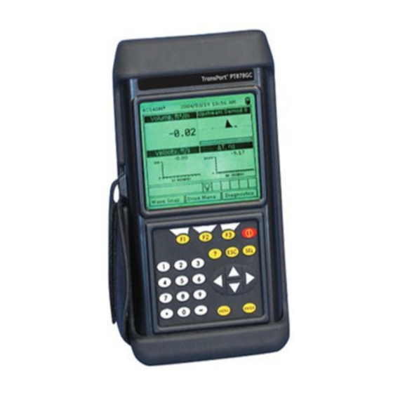
TransPort™ PT878GC
Portable Gas Flowmeter
Instruction Manual
910-229 B3
panametrics.com
August 2021
Related Manuals for Panametrics TransPort PT878GC
Summary of Contents for Panametrics TransPort PT878GC
-
Page 1
Flow TransPort™ PT878GC Portable Gas Flowmeter Instruction Manual 910-229 B3 panametrics.com August 2021… -
Page 3
User’s Manual 910-229 B3 August 2021 panametrics.com Copyright 2021 Baker Hughes company. This material contains one or more registered trademarks of Baker Hughes Company and its subsidiaries in one or more countries. All third-party product and company names are trademarks of their respective… -
Page 4
[no content intended for this page]… -
Page 5: Table Of Contents
Contents Features and Capabilities ………………1 1.1.1 Overview .
-
Page 6
Contents 4.1.9.1 Entering General-Purpose Analog Inputs …………61 4.1.9.2 Entering Analog Inputs in Standard Volume or Mass Flow Option . -
Page 7
Contents Logging Data ………………..121 8.1.1 Entering the Logging Menu . -
Page 8
Contents 9.1.10.7 Testing the Battery …………….167 9.1.11 Resetting to Factory Default Parameters . -
Page 9
Contents 11.1.4.3 Pipe Materials ………………185 11.1.4.4 Accuracy. -
Page 10
Contents viii TransPort™ PT878GC User’s Manual… -
Page 11: Features And Capabilities
Chapter 1. Chapter 1. Features and Capabilities ® The TransPort Model PT878GC is a transit-time clamp-on gas flowmeter which combines all the features of a full-size gas flowmeter with the advantages of a portable instrument. This section describes the TransPort features and general system, and explains the theory of operation. 1.1.1 Overview The PT878GC is available in two models.
-
Page 12: System Description
Chapter 1. 1.1.2 System Description The TransPort is only one part of the flowmeter system. The other part of the system is the flowcell, which consists of the pipe and the transducers. 1.1.2.1 The Flowcell The flowcell is that part of the system that uses ultrasonic pulses to interrogate the flow. It consists of the flowcell pipe and the transducers.
-
Page 13: Electronics Package
Chapter 1. 1.1.2.2 Electronics Package The TransPort consists of circuits that generate, receive, and measure the travel time of the ultrasonic pulses. It also contains a microcomputer that controls operation and calculates flow measurement parameters. Specific circuits function as follows: TRANSMIT SIGNAL GENERATOR — The transmit signal generator, under control of the microcomputer and timing circuit, synthesizes the signal that drives the transmitter.
-
Page 14: Theory Of Operation
Chapter 1. 1.1.3 Theory of Operation The TransPort is a transit-time ultrasonic flowmeter. When ultrasonic pulses are transmitted through a moving liquid or gas, the pulses that travel in the same direction as the fluid flow (downstream) travel slightly faster than the pulses that travel against the flow (upstream).
-
Page 15: Initial Setup
Chapter 2. Chapter 2. Initial Setup Before making measurements, you must prepare the TransPort for operation. This includes the following procedures: • Making Electrical Connections • Charging and/or Replacing Batteries • Powering On and Off • Using the Screen and Keypad •…
-
Page 16
Chapter 2. Figure 3: Connection Locations TransPort™ PT878GC User’s Manual… -
Page 17: Power Connections
Chapter 2. 2.1.1.1 Power Connections The PT878GC is powered by either a 100-120/200-260 VAC wall mount plug-in module, or by 5 internal C -size NiCad high-energy rechargeable batteries or by a pack of 3.0 Ahr NiMH batteries. (An optional power supplement, part #703-1283, uses 6 AA alkaline batteries.) When you receive the PT878GC, the batteries are not charged;…
-
Page 18: Charging And/Or Replacing Batteries
-size NiCad high energy rechargeable batteries (Panametrics Sensing Part Number 200-058) or 3.0 Ahr NiMH batteries (part number 200-081). To replace the batteries, remove the rubber boot, open the panel located on the back of the PT878GC unit, disconnect the batteries, and replace with new ones (see Figure 4 below).
-
Page 19: Powering On And Off
PT878GC emits a short beep and displays a “PCI Loader” message. It then validates the instrument programming, and then displays the Panametrics Sensing logo and the software version and emits a long beep. If the meter fails any of these tests, contact Panametrics Sensing.
-
Page 20
Chapter 2. ABC.SIT 2004/11/30 09:53 AM Velocity, ft/s Signal, dB 0.00 Volume, l/s Delta-T, ns 0.10 E0: No Errors Figure 5: Screen After Powering On To turn the PT878GC off, press the red key for 3 seconds. The screen now appears similar to Figure 6 below. Velocity, ft/s Signal, dB SHUTDOWN: Meter OFF… -
Page 21: Using The Screen And Keypad
Chapter 2. 2.1.4 Using the Screen and Keypad The essential features for operating the TransPort are the screen and keypad. Although these features are common on portable instruments, the PT878GC design offers unique features to simplify and speed operation. 2.1.4.1 Screen The primary function of the screen is to display information in order for you to accurately and easily take measurements.
-
Page 22
Chapter 2. Table 3: Icons in the System Tray Icon Function Meaning Stopwatch Calibration Gate Operation: Watch is stopped when the gate is closed, or runs when it is open. (See page 3-46.) Snapshot Indicates that the Snapshot (To file) function has been activated, so users can take screen (To Printer) -
Page 23: Keypad
[ESC] — enables you to exit menus or menu options at any time; cancels numeric entry. • Red key [ ] turns the power on or off, and toggles the backlight on or off. Figure 8: The TransPort PT878GC Keypad TransPort™ PT878GC User’s Manual…
-
Page 24: Obtaining On-Line Help
Chapter 2. 2.1.5 Obtaining On-Line Help The TransPort offers on-line help screens that describe various features. You can access on-line help at any time by pressing the [?] key. The screen appears similar to Figure 9 below. Help Velocity, ft/s Signal, dB Table of Contents Use the arrows and the enter key to…
-
Page 25: Installing The Dampening Material, Transducers And Fixtures
Since the PT878GC is specifically designed for gas measurement with clamp-on transducers, it requires the use of specially designed fixtures and dampening material to maintain the highest possible measurement accuracy. Panametrics Sensing supplies the CFG series of fixtures: • The V1 clamping fixture for pipes with diameters between 0.75 and 1.25 in.
-
Page 26
Chapter 3. CFG-V1 CFG-V8 Layout Wrap PI Fixture Dummy Block Chain Strap Figure 10: The V Series and PI Fixtures Choosing the transducer installation locations on the pipe is an important aspect of proper flow measurement. Specifications assume a fully developed flow profile typically requiring 20 diameters upstream and 10 diameters downstream of straight pipe run. -
Page 27: Application Requirements
Chapter 3. 3.1.1 Application Requirements Before you begin to use the PT878GC, you should ensure that your meter can handle the frequencies required for your particular application. To check the capabilities of your particular PT878GC, refer to the back label of the PT878GC, shown in Figure 11 below.
-
Page 28
Chapter 3. Table 4: PT878GC Installation Requirements for Air, Nitrogen, Oxygen or Argon Maximum Velocity, ft/s (m/s) Min. Single Dual Four Pipe Size ANSI Pipe Wall Inches Transducer Pressure Travers Travers Triple Travers Five (DIN) (mm) psig (bar) Traverse Traverse 3/4 (20) <0.07 (1.8) 60 (5.1) -
Page 29
Chapter 3. Table 4: PT878GC Installation Requirements for Air, Nitrogen, Oxygen or Argon Maximum Velocity, ft/s (m/s) Min. Single Dual Four Pipe Size ANSI Pipe Wall Inches Transducer Pressure Travers Travers Triple Travers Five (DIN) (mm) psig (bar) Traverse Traverse 10 (250) <0.37 (9.4) 60 (5.1) -
Page 30
Chapter 3. Table 5: PT878GC Installation Requirements for Natural Gas Maximum Velocity, ft/s (m/s) Min. Pipe Size ANSI Pipe Wall Transduce Pressure Dual Triple Four (DIN) Inches (mm) r MHz psig (bar) Single Traverse Traverse Traverse Traverse 2 (50) <0.16 (4.1) 200 (14.8) 110 (33.5) 88 (26.8) -
Page 31
Chapter 3. Table 6: PT878GC Installation Requirements for Steam Maximum Flow Velocity Pipe Wall Min. ft/s (m/s) Pipe Size Inches Transducer Pressure Single in. (mm) (mm) (MHz) psig (bar) Traverse 3 (80) <0.22 (5.6) 110 (8.6) 120 (36.6) <0.3 (7.6) 200 (14.8) 4 (100) <0.24 (6.1) -
Page 32: Preparing The Pipe
Chapter 3. 3.1.2 Preparing the Pipe Locate a transducer measurement point with 20 diameters of upstream straight run pipe and 10 diameters of downstream straight run pipe. In addition, the point should be at least 10 diameters from any butt welds or flanges.
-
Page 33: Performing A Pipe Survey
Chapter 3. 3.1.2.1 Performing a Pipe Survey Finding a location where the pipe is concentric is important for optimum accuracy and performance. If possible, perform a pipe survey with an ultrasonic thickness gauge to find the best location. Clear rust or loose paint and measure the wall thickness at five points along the pipe axis at 25 mm (1-in.) intervals using an ultrasonic thickness gauge, as shown in Figure 13 below.
-
Page 34: Obtaining The Transducer Spacing
Chapter 3. 3.1.2.2 Obtaining the Transducer Spacing Using the measured OD and the pipe wall thickness, program the PT878GC (discussed in Chapter 4, Programming Site Data) to determine the required transducer spacing. To determine the PT878GC correction factor, calculate the mean inside pipe diameter (ID) and the pipe ID at the transducer locations.
-
Page 35: Installing The V Series Clamping Fixture And Transducers
Note: If you are using a V4 fixture with a 1.5 to 2-in. pipe, Panametrics Sensing suggests removing the set screws and the mounting bracket, rotating them and the transducer yoke 180°, and replacing the bracket, yoke and screws for a more secure fit.
-
Page 36
Chapter 3. The two fixture halves have measuring scales; ensure that the scales are on the same side of the fixture, so that both zeros start at the same origin, as shown in Figure 17 below. Figure 17: Fixture with Scale Origins Properly Aligned Install the four nuts onto the threaded rods with the convex side of the nut facing the fixture. -
Page 37: Installing The Transducers
Chapter 3. 3.1.3.2 Installing the Transducers Apply a bead of couplant 6 mm (0.25 in.) wide along the entire length of each transducer face, as shown in Figure 19 below. Figure 19: Couplant on Transducer Face Note: Do not slide the transducer with couplant along the surface of the pipe when mounting the transducer. Set the first mounting block (either left edge or right edge) at a convenient number on the scale, such as 1 in.
-
Page 38: Installing The Pi Fixture And Transducers
The PI clamping fixture holds transducers on pipes from 8 to 24 in. in diameter. It comes with either a chain or strap, depending on the selection made with the initial order from Panametrics Sensing. To install the fixture and transducers, complete the following steps: 3.1.4.1…
-
Page 39
Chapter 3. Figure 23: Marking the 3 o’Clock Position To find the coinciding point on the opposite site of the pipe (180° away from each other), divide the measured circumference by 2 and measure this distance along the circumferential lines from the zero point, as shown in Figure 24 below. -
Page 40: Installing The First Bracket With A Chain Or Strap
Chapter 3. 3.1.4.2 Installing the First Bracket with a Chain or Strap The following steps describe how to install the PI fixture with a supplied chain or strap. Carefully wrap the chain or strap around the pipe, taking care not to twist it. Loosen the wing nuts up to the end of the J-hooks.
-
Page 41: Installing The Transducers
Chapter 3. Line up the other edge of the CFG-PI holder bracket with the scribe line and tighten the chain or strap, as shown in Figure 29 below. Mark on Opposite Scribe Line Rear Edge of Second Block Figure 29: Lining up the Rear Edge of the Bracket with the 180° Scribe Line The spacing should now appear similar to that shown in Figure 30 below.
-
Page 42
Chapter 3. With one hand, mount one transducer into the PI fixture. With the other hand, tighten the transducer hold down screw, gradually pushing the transducer down to the pipe surface. Use a wrench to tighten the backing nut to prevent loosening due to vibration and thermal expansion. -
Page 43: Installing Dampening Material
• The DMP-3 is a clay-like compound for all temperature applications. If the temperature is over 150°F, the PDJ pipe dampening jacket (available from Panametrics Sensing with preapplied DMP-3) must be used with the material. At a minimum, you should consider applying dampening material if you have any of the following conditions: •…
-
Page 44: Installing Dmp-1 Dampening Material
Chapter 3. 3.1.5.1 Installing DMP-1 Dampening Material Be sure the CFG-V clamping fixture is installed on the pipe with the transducers as described in the section Installing the V Series Clamping Fixture and Transducers on page 25. With a marker, mark scribe lines on the inside edges of the brackets onto the pipe.
-
Page 45
Chapter 3. Figure 34: DMP-1 Material with Transducer Footprint Cut Out To remove any residual adhesive, clean the cut-out area with a rag or a piece of sandpaper, or use varnish remover. 10. Reinstall the fixture and transducers on the pipe. Lay the second strip of dampening material flat. -
Page 46: Installing Dmp-1 Dampening Material With Pi Fixture
Chapter 3. 3.1.5.2 Installing DMP-1 Dampening Material with PI Fixture Be sure the PI clamping fixture is installed onto the pipe with the transducers as described in the section Installing the PI Fixture and Transducers on page 28. Approximate the axial distance from one transducer face to the other transducer face, as shown in Figure 36 below.
-
Page 47: Installing Dmp-3 Compound With All Fixtures
Chapter 3. 3.1.5.3 Installing DMP-3 Compound with All Fixtures Be sure the fixture and transducers are installed on the pipe as described in the previous sections of this chapter. Remove the fixture and transducers, but be sure to mark the approximate area of installation. Remove any loose paint or rust with a file or emery cloth, as shown in Figure 38a below.
-
Page 48: Installing The Pdj Dampening Jacket
Chapter 3. Figure 41: Clearing DMP-3 from the Transducer Location (a) and Installing the Transducers (b) Apply the couplant to the transducers, and install the transducers onto the pipe. Note: If the measurement point is near a flange or weld, apply DMP-3 between that structure and the fixture as well.
-
Page 49
Chapter 3. WARNING! The pipe and the dripping fluid will cause severe burns upon contact with bare skin. Also, be sure not to inhale the fumes generated during the DMP-3 curing cycle. Install the fixture over the jacket, adjusting the spacing to match the prestamped transducer holes and PT878GC spacing calculations. -
Page 50
Chapter 3. TransPort™ PT878GC User’s Manual… -
Page 51: Programming Site Data
Chapter 4. Chapter 4. Programming Site Data On the PT878GC, a Program Menu (part of the Main Menu) enables you to enter information that is specific to each site: • Transducer types and paths • Pipe materials and linings • Fluid types •…
-
Page 52: Entering Transducer Parameters
Press [ENTER] or [SEL] to confirm the choice. IMPORTANT: While wetted transducers are listed as a choice, the PT878GC is designed for use with Shear wave clamp-on transducers. Consult Panametrics before selecting wetted transducers. Note: The choices made earlier in the Transducer and Pipe options determine the prompts available later. If the PT878GC does not scroll to a particular parameter, it is not necessary for that transducer or pipe type.
-
Page 53: Parameters For Special Transducers
From the Wedge Temp prompt, press the [ ] key to reach the Wedge SS prompt, and press Use the numeric keys to enter the Panametrics Sensing-supplied wedge sound speed (in ft/sec or m/sec) and press [ENTER]. Pressing the [] key returns the meter to the Transducer tab at the top.
-
Page 54: Entering Pipe Parameters
Chapter 4. 4.1.3 Entering Pipe Parameters To enter the Pipe option, scroll to the Pipe entry on the Program Menu and press [ENTER]. (From the Transducer window, you can scroll back up to the Transducer tab and press the [ ] arrow key to reach the Pipe window and …
-
Page 55
Chapter 4. The first prompt asks you to select the pipe material. [ENTER] Press to enter the material prompt. A drop-down list of materials opens. Table 7 below lists the available preprogrammed materials on the list. Press the [ ] or [ ] keys to scroll to the appropriate material, or scroll to “Other”… -
Page 56
Chapter 4. Note: The measurement units shown depend on the choices you have made in the English/Metric window of the Meter menu. If you select a material that has the Schedule option: [ENTER] The prompt asks if you wish to apply DIN (the DIN schedule). Press to select (or deselect) the DIN box. -
Page 57: Entering Pipe Lining Parameters
Press [ENTER] to confirm your choice. Note: If your pipe lining is not on the drop-down list, consult Panametrics Sensing for further information. The program follows one of two paths: If you have selected a preprogrammed material, the PT878GC automatically supplies the correct sound speed, and you proceed to step 3.
-
Page 58: Entering Fluid Types And Speeds
Chapter 4. 4.1.5 Entering Fluid Types and Speeds To access the Fluid option, scroll to the Fluid entry on the Program Menu and press [ENTER]. (If you are already in the Transducer/Pipe form, press the [] arrow key to reach the Fluid window, and press [ENTER].) The screen appears similar to Figure 48 below.
-
Page 59: Entering The Signal Path Parameters
Chapter 4. 4.1.6 Entering the Signal Path Parameters To enter the Path option, scroll to the Path entry on the Program Menu and press [ENTER]. (From the Lining window, you can scroll back up to the Lining tab and press the [] arrow key to reach the Path window, and press [ENTER].) The screen appears similar to Figure 49 below.
-
Page 60: Path Parameters For Clamp-On Transducers
[ENTER] to confirm the entry. If you enter an invalid entry, the PT878GC rejects the entry and displays an error message. Note: Panametrics Sensing does not recommend using a spacing other than the one calculated by the PT878GC. After you enter the spacing, pressing the [ ] key returns the prompt to the Traverses box, and then to the Path tab at the top of the screen.
-
Page 61
Chapter 4. The first prompt asks if you want to disable or enable the Standard Volume option. Use the [ ] and [ ] keys to scroll to the appropriate radio button. Press [ENTER] to confirm your selection. Note: If you select “Disabled,”… -
Page 62: Entering Inputs In The Standard Volume Option
Chapter 4. 4.1.7.1 Entering Inputs in the Standard Volume Option To enter input parameters in the Standard Volume/Mass Flow option, return to the Settings tab at the top of the Standard Volume window. Press the [] arrow key and [ENTER] to open the Inputs window. The screen appears similar to Figure 51 below.
-
Page 63
Chapter 4. The next prompt appears if you have selected a fixed pressure. The PT878GC asks for the fixed pressure value. [ENTER] Press to open the text box. Use the numeric keys to enter the known pressure. Press [ENTER] to confirm the entry. Whether you have selected a fixed or an active supply, the PT878GC asks for the desired input. -
Page 64: Entering Mass Flow Parameters
Chapter 4. 4.1.7.2 Entering Mass Flow Parameters To enter mass flow parameters in the Standard Volume/Mass Flow option, press the [] arrow key until you reach the Mass Flow tab, and then press [ENTER] to open the Mass Flow window. The screen appears similar to Figure 52 below. To step through each parameter, press the [] key.
-
Page 65: Entering Skan/Measure Parameters
M>S Switch value. The default value is 5.0 µsec and values from 0 to 250 µsec are acceptable. Note: Do not change this value without consulting Panametrics Sensing. If you wish to use Skan only, set the M/S Switch to a value of 0.
-
Page 66
Chapter 4. The program now asks if you wish to Limit the Measurement Delta. (The default is unchecked or off.) [ENTER] Press to enter the text box. Use the numeric keys to enter the recommended value in µsec. Press [ENTER] to confirm the entry. Pressing the [] key highlights the Advanced prompt. -
Page 67: Entering Skan/Measure Integrate Parameters
Chapter 4. 4.1.8.1 Entering Skan/Measure Integrate Parameters To enter parameters for the Skan/Measure Integrate mode in the Skan/Measure option, press the [] arrow key once to reach the Integrate tab. Then press [ENTER] to open the Integrate window, which appears similar to Figure 55 below.
-
Page 68: Entering Skan/Measure Count Parameters
Chapter 4. 4.1.8.2 Entering Skan/Measure Count Parameters To open the Skan/Measure Count window in the Skan/Measure option, press the [] arrow key twice (from the All tab) to reach the Count tab. Press [ENTER], and the screen appears similar to Figure 56 below. Skan/Measure Integrate Count…
-
Page 69: Entering Skan/Correlation Parameters
Chapter 4. 4.1.8.3 Entering Skan/Correlation Parameters To open the Skan/Correlation window in the Skan/Measure option, press the [] arrow key three times (from the All tab) to reach the Correlate tab, and press [ENTER]. The screen appears similar to Figure 57 below. Skan/Measure Integrate Count…
-
Page 70
Chapter 4. Repeat step 1 to enter the maximum percentage of peak. The next prompt asks for the Percent of Peak, which is used to calculate the transit times and Delta-T. [ENTER] Press to enter the text box. Use the numeric keys to enter the desired value. Press [ENTER] to confirm the entry. -
Page 71: Entering Analog Inputs
Chapter 4. 4.1.9 Entering Analog Inputs The Analog Inputs option enables you to specify parameters for general purpose or standard volume inputs. To enter the Analog Inputs option, scroll to the Analog Inputs entry on the Program Menu and press [ENTER]. If you have not enabled the Standard Volume Option (see page 4-18), the screen appears similar to Figure 58 below.
-
Page 72
Chapter 4. Use the four arrow keys to scroll to the desired letter or symbol, and press [ENTER] to add the letter to the label. Note: Pressing [SEL] causes the screen to alternate between a set of upper-case (capital) letters, a set of lower-case letters, and a set of symbols. -
Page 73: Entering Analog Inputs In Standard Volume
Chapter 4. 4.1.9.2 Entering Analog Inputs in Standard Volume or Mass Flow Option If you have enabled the Standard Volume or Mass Flow options, the screen displays different options, as shown in Figure 60 below. Analog Input Input A Input B Pressure Function Label…
-
Page 74: Entering The Analog Output
Chapter 4. 4.1.10 Entering the Analog Output The Analog Output option enables you to enter information to set up output parameters. To enter the option, scroll to the Analog Output entry on the Program Menu and press [ENTER]. The screen appears similar to Figure 61 below. To step through each parameter, press the [] key.
-
Page 75
Chapter 4. [ENTER] Press to open the window. Scroll to the desired output type. Press [SEL] to confirm your selection. The prompt then moves to a list of unit types. (The available units depend on the selection made at the Data Source prompt.) Scroll to the desired output unit. -
Page 76: Entering The Digital Output
Chapter 4. 4.1.11 Entering the Digital Output While resembling the Analog Output option, the Digital Output option enables you to set up parameters necessary for a digital output. To enter the option, scroll to the Digital Output entry on the Program Menu and press [ENTER]. The screen appears similar to Figure 63 below.
-
Page 77
Chapter 4. • Temperature • Volume • User Function • Skan/Measure • Mass Flow [ENTER] Press to open the data source selection window, shown in Figure 62. Scroll to the desired source. Press [SEL] to confirm your selection. The prompt then moves to a list of unit types. (The available units depend on the selection made at the Data Source prompt.) Scroll to the desired output unit. -
Page 78: Entering User Functions
Chapter 4. [ENTER] Press to open the drop-down menu. Scroll to the required mode. Press [ENTER] to confirm your selection. Stopwatch Totalizer Through the Gate Input option, you can implement the Stopwatch Totalizer function to measure totals manually. To set up the Totalizer function: At the Gate Active prompt, select Contact Closed.
-
Page 79
Chapter 4. “ ‘ < > Cancel Delete Figure 65: The Text Creation Window Use the four arrow keys to scroll to the desired letter or symbol, and press [ENTER] to add the letter to the label. Note: Pressing [SEL] causes the screen to alternate between a set of upper-case (capital) letters, a set of lower-case letters, and a set of symbols. -
Page 80: Entering Correction Factors
When you have completed entering the function, press [F3] (OK) to confirm the entry and return to the User Function window. Panametrics Sensing recommends pressing [F2] (Check) to test the validity of the function. The PT878GC displays either “OK” or a message such as “Syntax Error.”…
-
Page 81: Entering Reynolds Correction
Chapter 4. Correction Factors Calibration Factor Reynolds Correction Inputs Re Correction K/V Factors Single Table K/V x 10 Data Source Edit Table Cancel Figure 67: Reynolds Correction Window 4.1.13.1 Entering Reynolds Correction The first prompt asks if you want to enable the Reynolds Correction factor, a number based on the Kinematic Viscosity and flow rate of the gas.
-
Page 82: Entering A Calibration Factor
Chapter 4. The prompt then asks if you wish to edit the Reynolds Correction table. [ENTER] Press to open the table, which appears similar to Figure 68 below. Edit Reynolds Table Inputs Data Source Cancel Figure 68: Window for Reynolds Correction Table Use the numeric keys to enter the first value for the data source, and press [ENTER] to confirm the entry.
-
Page 83
Chapter 4. Correction Factors Reynolds Correction Calibration Factor Inputs Calibration Factor K Factor Single Table Meter K-Factor 1.0000 Data Source Edit Table Edit Table Cancel Figure 69: The Calibration Factor Window The first prompt asks if you wish to enable the calibration factor. … -
Page 84
Chapter 4. Edit KFactor Table Inputs KFactor Data Source Cancel Figure 70: The KFactor Table Use the numeric keys to enter the first value for the data source, and press [ENTER] to confirm the entry. Press the [ ] key to move to the KFactor column. Use the numeric keys to enter the corresponding value, and press [ENTER] to confirm the entry. -
Page 85: Creating And Managing Sites
Chapter 5. Chapter 5. Creating and Managing Sites The PT878GC can store site data in files for current and future access. (To learn how to program setup data, refer to Chapter 4, Programming Site Data.) After you answer the necessary questions, simply save the information to a site file.
-
Page 86
Chapter 5. Site Manager File Site Sort Info: DEFAULT:SIT DEFAULT New Site **CURRENT SITE** 03/04/04 14:51:10 5111 bytes 118272 bytes free Refresh Exit Figure 72: The Site Manager Window Note: Each PT878GC comes preprogrammed with a basic site, Default, which serves as a basis for saving data and creating other sites. -
Page 87: Creating A New Site
Chapter 5. • To open an existing site (thus replacing the current site), go to page 79. • To save a current site, go to page 79. • To refresh site information, go to page 81. • To rename a site, go to page 81. •…
-
Page 88
Chapter 5. New Site New Site Use the selected site ‘DEFAULT.SIT’ as a template? Figure 75: Template Confirmation Window The meter returns to Operate Mode, with the new site name displayed in the upper left corner of the screen. TransPort™ PT878GC User’s Manual… -
Page 89: Opening An Existing Site
Chapter 5. 5.1.1.2 Opening an Existing Site If you want to return to a second site that you have previously saved, first highlight the replacement site in the left window of the Site Manager. Then press [MENU] to open the File Menu. Scroll to the Open option, and press [ENTER]. The screen appears similar to Figure 76 below.
-
Page 90
Chapter 5. Save Site Save the current site (DEFAULT.SIT)? Figure 77: The Save Current Site Window • Press [F2] (No) to cancel saving the site, or • Press [F3] (Yes) to save the site. The PT878GC remains in the current window (Operate Mode or Site Manager), with the current site saved. TransPort™… -
Page 91: Saving A Site With A Different Name
Chapter 5. 5.1.1.4 Saving a Site with a Different Name If you want to save the current site with a different name, open the Site Manager, press [MENU] to open the File Menu, scroll to the Save As option, and press [ENTER]. The screen appears similar to Figure 78 below. Save Current Site Delete Cancel…
-
Page 92: Deleting A Site
Chapter 5. Rename Site DEFAULT Delete Cancel Figure 79: The Rename Site Window Use the four arrow keys to scroll to the desired letter or number, and press [ENTER]. Repeat this procedure until you have created the desired site name. (Press [F1], Delete, to remove any unwanted letters or numbers.) When you have finished, •…
-
Page 93: Creating A Site Message
Chapter 5. 5.1.1.8 Creating a Site Message The Site Message option allows you to add an explanatory message (with up to 30 characters or spaces) for any given site. To create a site message: Press [MENU] to enter the File Menu. Then press the [] arrow key once to scroll from the File Menu to the Site Menu.
-
Page 94
Chapter 5. Use the four arrow keys to scroll to the desired letter or symbol, and press [ENTER] to add the letter to the message. Note: Pressing [SEL] causes the screen to alternate between a set of upper-case (capital) letters, a set of lower-case letters, and a set of symbols. -
Page 95: Printing A File
Chapter 5. 5.1.1.9 Printing a File To print a file from the Site Manager, press [MENU] to enter the File Menu, press the [] arrow key once, scroll to the Print option, and press [ENTER]. The PT878GC shows a message indicating that its infrared scanner is looking for a receiving device.
-
Page 96: Transferring A File From A Pc To The Pt878Gc
Chapter 5. 5.1.1.12 Transferring a File from a PC to the PT878GC Once you have stored site or meter files to a PC, you can then transfer them back to the PT878GC over the IR interface. The PT878GC only accepts files with a .sit (site) or .met (meter) extension. If you rename another type of file with one of these extensions and transfer it, it will be transferred, but will not function if you open it.
-
Page 97: Listing Files By Name
Chapter 5. 5.1.1.13 Listing Files by Name If you want to list your files alphabetically by site name within the Site Manager, press [MENU] to open the File Menu. Then press the [] arrow key twice to scroll from the File Menu to the Sort Menu, shown in Figure 85 below. Press [ENTER].
-
Page 98
Chapter 5. TransPort™ PT878GC User’s Manual… -
Page 99: Displaying And Configuring Data
Chapter 6. Chapter 6. Displaying and Configuring Data The PT878GC allows you to view from one to four different measurement parameters simultaneously. The screen can show these parameters not only in numeric format, but as line or bar graphs as well. You can configure any given measurement for your particular requirements.
-
Page 100
Chapter 6. Number Format Programming Fixed Decimal Format Decimal Places Cancel Figure 87: The Number Format Window The first entry, Format, asks you to select the numeric format from three choices: fixed decimal, default and scientific. Default provides the default resolution, while Fixed Decimal allows users to override the standard resolution. -
Page 101: The View Option
Chapter 6. 6.1.2 The View Option The second option, View, allows you to select the presentation of a parameter in one of three formats: numeric, line graph or bar graph. From the Display Menu, press the [] key once to reach the View option, and then press [ENTER]. A drop-down menu shows the three formats.
-
Page 102: The Limits Option
Chapter 6. 6.1.3 The Limits Option Once you have configured a parameter as a line or bar graph, you might need to change its presentation or values. The Limits option (replacing the Format option for line and bar graphs) enables you to program the minimum or maximum values displayed, the time interval and the display of the average value.
-
Page 103: The Measurement Option
Chapter 6. 6.1.4 The Measurement Option On occasion, you might need to change the actual parameter measured in a given window.The Measurement option enables you to reconfigure the window with one of five categories of data source (velocity, volume, forward or reverse totalizer, or diagnostics) and appropriate English or metric measurement units.
-
Page 104: Customizing The Display Screen
Chapter 6. 6.1.5 Customizing the Display Screen You might wish to display one or two parameters, or customize the soft keys to quickly access particular menus. The Site Menu enables you to make more comprehensive changes in your display screen. To enter the Site Menu, press the [MENU] key at the lower right of the PT878GC keypad.
-
Page 105: Specifying The Number Of Displayed Parameters
Chapter 6. 6.1.5.1 Specifying the Number of Displayed Parameters As mentioned earlier, the PT878GC can display one to four different measurement parameters simultaneously. However, sometimes you might wish to display only one or two parameters. To change the number of open display windows: Press [MENU].
-
Page 106: Customizing Softkeys
Chapter 6. 6.1.5.2 Customizing Softkeys When the screen is in Operate mode, you might wish to access a particular submenu frequently without the trouble of scrolling through menus. Customizing the softkeys (the function keys —[F1], [F2] and [F3]) allows you to access up to three submenus by pressing the associated softkey.
-
Page 107
Chapter 6. Press [ENTER] to confirm the entry, and press [F3] (OK) to confirm the entry and close the window. (Press [F2] (Cancel) to close the window without changing the key.) The screen now appears similar to Figure 6-10 on the next page, with the [F1] window displaying “Contrast.” Pressing [F1] opens the Contrast window. -
Page 108: Managing Files — The Drive Manager
Chapter 6. 6.1.6 Managing Files — The Drive Manager On occasion, you might want to review, print or transfer some or all of the files in the PT878GC. The Drive Manager allows you to view all the files stored in the meter. To open the Drive Manager: Press [MENU].
-
Page 109
Chapter 6. The window on the left lists all the meter, site and log files in the PT878GC, while the window on the right displays information on the file highlighted in the left window. File Manager File Sort Transfer Info: SYSLOG.MET SYSLOG. -
Page 110: Refreshing A File
Chapter 6. 6.1.6.1 Refreshing a File You can refresh a file (updating the display with the most current information) in one of two ways: • Press [F2], Refresh, to refresh the highlighted file. • From the File Menu, scroll to the Refresh option and press [ENTER]. The updated information on the highlighted file appears in the window on the right.
-
Page 111
Chapter 6. Note: For Windows NT 4.0, check that the QuickBeam software (available through the path C:\Program Files\QuickBeam Suite) is running, and that the IR beam on the PT878GC has clear access to the IR sensor connected to the PC port. You can send the file in one of two ways: •… -
Page 112: Deleting A File
Chapter 6. 6.1.6.4 Deleting a File To delete a file in the File Manager, first be sure you have highlighted that site in the left window of the File Manager. Then press [MENU], scroll to the Delete option, and press [ENTER]. The screen appears similar to Figure 100 below. File Manager Delete Confirmation File…
-
Page 113: Listing Files By Name
Chapter 6. 6.1.6.5 Listing Files by Name If you want to list your files alphabetically by site name within the File Manager, press [MENU] to open the File Menu. Then press the [] arrow key to scroll from the File Menu to the Sort Menu, shown in Figure 101 below. Press [ENTER]. The File Manager screen refreshes, with the sites listed in alphabetical order.
-
Page 114: Accessing Meter Data -The About Option
While the window normally appears briefly at startup, users might want to access the information for a longer period. To open the About window, scroll to the About option on the Site Menu and press [ENTER]. The screen appears similar to Figure 102 below. Panametrics Sensing PT878GC Portable Flowmeter Copyright ©2002 Baker Hughes All rights reserved.
-
Page 115: Programming Meter Settings
Chapter 7. Chapter 7. Programming Meter Settings Along with display formats and site data, PT878GC users can program global settings for the meter that suit their individual preferences. The global settings include: • English or Metric measurement units • Battery power •…
-
Page 116: Entering The Meter Menu
Chapter 7. 7.1.1 Entering the Meter Menu To enter the Meter Menu, press the [MENU] key at the lower right of the PT878GC keypad. The Main Menu replaces the Status Bar at the top of the screen. Press the [ ] arrow key twice to scroll from the Site Menu to the Meter Menu.
-
Page 117
Chapter 7. Meter Settings Units English Metric Pressure Units: Date: Bars 2000/11/1 Time: 10:08:53 AM Cancel Figure 104: The Meter Settings Window At the Units prompt, use the [ ] and [ ] keys to scroll between English and Metric units. Press [ENTER] to confirm the choice. -
Page 118: The Battery Charger
Chapter 7. 7.1.3 The Battery Charger The Battery option allows you to monitor the current run time and status of the internal rechargeable batteries, as well as to condition NiCad batteries to maintain the maximum life possible. Conditioning NiCad batteries (a process that can take up to 12 hours for a fully charged pack) discharges the pack completely and then performs a fast charge.
-
Page 119: Entering Date And Time
Chapter 7. 7.1.4 Entering Date and Time In Operate mode, the Status Bar displays the current date and time above the measurements in the upper right corner of the screen. The Date/Time option allows you to set the date or time, which are required for correct data logging operation.
-
Page 120: Changing Date And Time Appearance (Locale)
Chapter 7. 7.1.5 Changing Date and Time Appearance (Locale) In addition to setting the correct date and time, you can also change its presentation to suit local preferences. You can select a time display of AM/PM or 24-hour time To alter the time and date display: From the Meter menu, scroll to the Locale entry and press [ENTER].
-
Page 121
Chapter 7. The PT878GC now asks you to select whether you want the time presented in a 12-hour format (for example, 11:53:23 PM) or in a 24-hour format (23:53:23). [ENTER] Press to open the drop-down menu. Use the [ ] or [ ] arrow keys to scroll to the 12-hour or 24-hour entry. -
Page 122: Adjusting The Contrast
Chapter 7. 7.1.6 Adjusting the Contrast For more comfortable viewing in a particular environment, the PT878GC enables you to adjust the screen contrast. To adjust the screen contrast: From the Meter menu, scroll to the Contrast entry and press [ENTER]. The Display Options window opens on the …
-
Page 123: Setting Backlight Timeout
Chapter 7. 7.1.7 Setting Backlight Timeout By using the Backlight Timeout option, you can set a specified time that the PT878GC backlight will remain on before turning itself off. Automatic turnoff enables the PT878GC to conserve battery power. To set the backlight timeout: From the Meter menu, scroll to the Backlight entry and press [ENTER].
-
Page 124: Changing Communications Parameters
Cancel Figure 108: The Communications Window The first prompt asks for the node identification number, which can be any number from 1 to 240. IMPORTANT: Do NOT change the node ID unless instructed by Panametrics Sensing. [ENTER] Press to open the text box.
-
Page 125
Chapter 7. [ENTER] Press to open the drop-down menu. Use the [ ] or [ ] arrow keys to scroll to the desired parity. Press [ENTER] to confirm the entry. The next prompt asks you to select either one or two stop bits.The default number is one. Use the [ ] and [ keys to scroll to the desired number, and press [ENTER]. -
Page 126: Resetting Forward And Reverse Totals
Chapter 7. 7.1.9 Resetting Forward and Reverse Totals On occasion, it might be necessary to clear and reset the forward and reverse totals computed by the Forward and Reverse Totalizers. To reset the totals: From the Meter menu, scroll to the Totals entry and press [ENTER]. The window now appears similar to Figure 109 below.
-
Page 127: Setting Up User Tables
Chapter 7. 7.1.10 Setting Up User Tables When you program user functions (see page 68), you can also support them with up to six user tables of non-linear or empirical data. To program one or more user tables: From the Meter menu, scroll to the User Tables entry and press [ENTER]. The window now appears similar to Figure 110 below.
-
Page 128
Chapter 7. UserTable1 “ ‘ < > Delete Cancel Figure 111: The Text Creation Window Use the four arrow keys to scroll to the desired letter or symbol, and press [ENTER] to add the letter to the label. Note: Pressing [SEL] causes the screen to alternate between a set of upper-case (capital) letters and a set of symbols. -
Page 129
Chapter 7. Use the four arrow keys to move to the desired entry in the table. Press [ENTER]. Then use the numeric keys to enter the desired data, which appears in the right corner of the window above the table. Press [ENTER] to confirm the data, which then appears in the appropriate slot in the table. -
Page 130: Taking A Bitmap Capture Of A Current Screen
Chapter 7. 7.1.11 Taking a Bitmap Capture of a Current Screen The Snapshot option enables you to take a “screen capture” of the current screen in bitmap format (.bmp) for display or storage in a Windows-based PC. To take a “snapshot” of the screen: From the Meter menu, scroll to the Snapshot entry and press [ENTER].
-
Page 131: Logging Data
Chapter 8. Chapter 8. Logging Data A powerful and flexible feature of the PT878GC is data logging. The meter enables you to choose up to 12 parameters to log. You can also select the start time and date, end time and date, and time interval. Logs can run one at a time or simultaneously.
-
Page 132: Entering The Logging Menu
Chapter 8. 8.1.1 Entering the Logging Menu To enter the Logging Menu, press the [MENU] key at the lower right of the PT878GC keypad. The Main Menu replaces the Status Bar at the top of the screen. Press the [ ] arrow key three times to scroll from the Site Menu to the Logging Menu.
-
Page 133
Chapter 8. Log Manager File View Sort Info: AAA.LOG State: Finished S:03/01/04 13:13:41 E:03/01/04 13:23:41 Interval: 10 Seconds Records:51 03/01/04 13:23:21 1216 bytes 109568 bytes free Refresh Exit Figure 114: The Log Manager Window To access the menu for the Log Manager, press the [MENU] key. The cursor highlights the File Menu in the upper left … -
Page 134: The File Menu
Chapter 8. 8.1.3 The File Menu The File Menu allows you, not only to create new logs, but also to copy, rename or delete logs, as well as to print them or transfer them to a PC. To open the File menu from the Log Manager, press the [MENU] key and then [ENTER]. The screen appears similar to Figure 115 below.
-
Page 135: Setting Up A New Log
Chapter 8. 8.1.3.1 Setting up a New Log The New Log option enables you to create and set up parameters for a new log. You can access this option in two ways: • by scrolling to the New Log option in the Logging Menu (as shown in Figure 8-1 on page 8-2) and pressing [ENTER], or •…
-
Page 136
Chapter 8. General Measurements Log Name 10SEC.LOG Format Circular Linear Type Error Standard Start Date/Time 01:38:08 2004/11/01 End Date/Time 09:38:08 2004/11/01 Logging Interval secs Activate Cancel Figure 117: The General Log Format Window To step through each parameter, press the [] key. The first prompt asks you to choose between a linear or circular format for the log. -
Page 137
Chapter 8. Finally, press the [ ] key to move to the Measurements tab, and press [ENTER]. The Measurements window appears similar to Figure 118. General Measurements NO UNIT NO UNIT NO UNIT NO UNIT NO UNIT NO UNIT NO UNIT NO UNIT NO UNIT… -
Page 138: Copying (Cloning) A Selected Log
Chapter 8. The prompt then moves to a list of unit types. (The available units depend on the selection made at the Data Source prompt.) Scroll to the desired output unit. Press [F3] (OK) to confirm your selection. You can repeat this procedure for up to 12 different parameters. When you have finished, press [F2] (Cancel) to cancel the entries, or [F3] (Activate) to confirm the entries and start the log.
-
Page 139: Deleting All Logs
Chapter 8. Log Manager File Delete Programming Info:DEFAULT DEFAULT Delete Log ‘555.LOG?’ GLOBAL 1 View Figure 120: The Delete Confirmation Window 8.1.3.5 Deleting All Logs To clear the Log Manager and memory of all logs, open the File menu, scroll to the Delete All Logs option, and press [ENTER].
-
Page 140: The Log Menu
Chapter 8. message indicating that it is uploading the log. (The meter also displays a message if the upload fails.) When the upload is complete, the meter returns to the Log Manager. The PC holds the transferred log in a C\Ir_Inbox folder (C:\Ir_Inbox for Windows NT, C:\My Received Files for Windows 98, or Desktop for Windows 2000).
-
Page 141: Pausing All Logs
Chapter 8. The PT878GC returns to the Log Manager, which displays the highlighted log with a status of “Finished.” The space not used by the finished log is freed for reuse. Note: You cannot restart a finished log. You must create a new log with the same parameters. 8.1.4.4 Pausing All Logs To pause all logs that are currently pending or running, open the Log menu, scroll to the Pause All Logs option, and…
-
Page 142: The View Menu
Chapter 8. 8.1.5 The View Menu Through the View menu, you can view the data of individual logs in graphical or spreadsheet formats. To open the View menu from the Log Manager, press [MENU]. Scroll to the View menu, and press [ENTER]. The screen appears similar to Figure 122 below.
-
Page 143: Displaying Log Details
Chapter 8. 8.1.5.1 Displaying Log Details To view details of a given log, be sure the log is highlighted in the left window of the Log Manager. Then scroll to the View menu and press [ENTER]. Scroll to the Details option and press [ENTER]. The screen now appears similar to Figure 123 below.
-
Page 144: Displaying Log Data In Graphical Form
Chapter 8. 8.1.5.2 Displaying Log Data in Graphical Form To view a log in graphical form, be sure the log is highlighted in the left window of the Log Manager. Scroll to the View menu and press [ENTER]. Scroll to the Graph option and press [ENTER]. The “Select Measurement”…
-
Page 145
Chapter 8. The Y-Axis window allows you to specify whether the Y axis on the graph extends to the maximum value (Max), over the entire range (Range) or between certain specified values (Set). Use the [ ] and [ ] keys to scroll to the desired limit type. -
Page 146: Displaying Log Data In Spreadsheet Form
Chapter 8. 8.1.5.3 Displaying Log Data in Spreadsheet Form To view a log in spreadsheet form, be sure the log is highlighted in the left window of the Log Manager. Then scroll to the View menu and press [ENTER]. Scroll to the Spreadsheet option and press [ENTER]. The screen now appears similar to Figure 127 below.
-
Page 147: The Sort Menu
Chapter 8. 8.1.6 The Sort Menu The Sort Menu within the Log Manager allows you to arrange your log list either alphabetically (By Name) or chronologically (By Date). Log Manager Sort File View By Name Info: AAA.LOG State: Finished By Date S:03/01/04 13:13:41 E:03/01/04 13:23:41…
-
Page 148
Chapter 8. TransPort™ PT878GC User’s Manual… -
Page 149: Servicing The Pt878Gc
Chapter 9. Chapter 9. Servicing the PT878GC For user convenience, the PT878GC offers a Service Menu. This menu enables users to perform a variety of functions that they might occasionally require: • print out reports • calibrate the PT878GC • run diagnostics •…
-
Page 150: Entering The Service Menu
Chapter 9. 9.1.1 Entering the Service Menu To enter the Service Menu, press the [MENU] key at the lower right of the PT878GC keypad. The Main Menu replaces the Status Bar at the top of the screen. Press the [ ] arrow key four times to scroll from the Site Menu to the Service Menu.
-
Page 151
Chapter 9. Reports Reports Drive Contents Current Site Global Settings User Functions User Tables All User Settings Menu Commands All Reports Exit Print Figure 130: The Reports Window Press [ENTER] to open the drop-down list of available reports, as shown in Figure 130 above. Press the [ ]or [ arrow keys to scroll to the desired reports, and press [ENTER]. -
Page 152
Chapter 9. Figure 131: Printout of a Typical Drive Report TransPort™ PT878GC User’s Manual… -
Page 153: Setting Up The Thickness Gauge
Chapter 9. 9.1.3 Setting up the Thickness Gauge For greatest accuracy in flow applications, the PT878GC can measure pipe wall thickness using an optional thickness gauge transducer, instead of relying on the nominal pipe wall thickness. In Thickness Gauge mode, the PT878GC does not measure flow, but it can determine the thickness of most standard metal and plastic pipe materials over a range from 0.05 to 3 in.
-
Page 154: Measuring Pipe Wall Thickness
Measuring Pipe Wall Thickness 9.1.4.1 Entering the Material and Sound Speed IMPORTANT: Panametrics Sensing recommends calibrating the thickness gauge periodically (as discussed on page 148) before measuring thickness. To enter the Thickness Gauge Display option, scroll to the T-Gauge Display entry on the Service Menu and press [ENTER]. The screen appears similar to Figure 133 below.
-
Page 155: Measuring Thickness In Numeric Format
Chapter 9. 9.1.4.2 Measuring Thickness in Numeric Format To measure the actual thickness of a pipe, apply couplant to the calibrated thickness gauge transducer and hold the transducer steady against the pipe. Then press the [ ] or [ ] arrow key until you reach the Display tab and press [ENTER].
-
Page 156: Displaying The Receive Signal In Graphical Format
Chapter 9. 9.1.4.3 Displaying the Receive Signal in Graphical Format Used chiefly for diagnostic purposes, the Graph option helps to determine why the thickness gauge is not working if you suspect a problem. The graph shows an image of the acoustic signal. If the display does not show a signal image similar to Figure 9-7 below, you may have a problem with the transducer, couplant, or the programmed ®…
-
Page 157
Chapter 9. Thickness Gauge Measure Display Material Velocity Graph Zero Signal Display Figure 136: The Graph Window in Zoom Format • Press [F1] (In) to zoom in to magnify screen details. • Press [F2] (Out) to zoom out fully. • Press [F3] to toggle between the left and right cursors. … -
Page 158: Calibrating The Thickness Gauge Transducer
See Appendix C for more information. The next prompt asks you to enter the length of Block 1. (If you are using a Panametrics Sensing-supplied test block, the length is printed on the block.) Press [ENTER] to open the text box.
-
Page 159: Calculating Velocity (Pipe Material Sound Speed)
Chapter 9. • Press the [ ] or [ ] arrow key to move to another tab to take readings or perform a velocity calibration. • Press [F2] (Cancel) to return to Operate Mode without confirming the sound speed value. •…
-
Page 160
Chapter 9. Thickness Gauge Measure Display Velocity Graph Zero Material Block Length Press Set to Commit Value Current Calculated 22129. 74733. Cancel Figure 139: The Velocity Window, Displaying the Calculated and Current Values The “Calculated” box shows the thickness value measured. The PT878GC asks for confirmation of the calculated and current values. -
Page 161: Programming The Thickness Gauge
Noise Threshold • Detection Threshold IMPORTANT: The thickness gauge programming settings are entered at the factory. You should not change them unless instructed by Panametrics Sensing. The Programming window appears similar to Figure 140 below. Thickness Gauge Setup Programming Low Signal Thresh Transducer Delay µs…
-
Page 162
Chapter 9. Signal inversion should be on, unless you have received other instructions. To change its status, use the [ ] and [ arrow keys to move to the appropriate radio button and press [ENTER]. To enter the noise threshold: [ENTER] Press to open the text box. -
Page 163: Displaying Diagnostic Parameters
Chapter 9. 9.1.6 Displaying Diagnostic Parameters The Diagnostics option enables you to view current diagnostic parameters without having to open a display window in Operate Mode. To enter the option, scroll to the Diagnostics entry on the Service Menu and press [ENTER]. The screen appears similar to Figure 141 below.
-
Page 164: Calibrating The Analog Output And Inputs
Chapter 9. 9.1.7 Calibrating the Analog Output and Inputs The Calibration option allows you to calibrate the analog output and inputs. To enter the option, scroll to the Calibrate entry on the Service Menu and press [ENTER]. The screen appears similar to Figure 142 below. Calibrate/Test I/O Analog Input Analog Output…
-
Page 165: Calibrating Inputs
Chapter 9. 9.1.7.2 Calibrating Inputs To open the Inputs window, press the [ ] arrow key and press [ENTER]. The screen appears similar to Figure 143 below. Note: Calibrating the analog inputs requires use of a current source. Calibrate/Test I/O Analog Input Analog Output Input#…
-
Page 166: Setting Up Signal Parameters
The first prompt asks for the Delta-T offset. Delta-T is the difference between the upstream and downstream transit times of the transducers. The Delta-T offset should normally be set to zero. Note: Consult Panametrics Sensing before performing this step. [ENTER] Press to open the text box.
-
Page 167
The next prompt, the transmitter sample size, is the number of pulses each transmitter (upstream and downstream) emits. It is set to 8 by default. Note: Consult Panametrics Sensing before performing this step. [ENTER] Press to open the drop-down list. -
Page 168: Setting Up The Measurement Mode
Skan/Correlation mode, is used primarily for liquid flow measurement. Note: Do not change the measurement mode or values unless recommended by Panametrics Sensing. From the Signal Parameter tab, press the [] arrow key to move to the Meas Mode tab. The window appears similar to Figure 145 below.
-
Page 169: Setting Up Pulse/Code Parameters
Chapter 9. 9.1.8.2 Setting Up Pulse/Code Parameters When you select the Skan detection method, you must also choose what type of signal to send to the transducers: either a coded signal at 1, 2, 4, 11 or Twin bits, or a specific number of pulses to be sent. From the Meas Mode tab, press …
-
Page 170: Setting Error Limits
Chapter 9. 9.1.9 Setting Error Limits The Error Limits option enables you to set limits for an incoming signal. When the signal falls outside the programmed limits, an error indication appears. To enter this option, scroll to the Error Limits entry on the Service Menu and press [ENTER].
-
Page 171
Chapter 9. Use the numeric keys to enter the desired speed. Press [ENTER] to confirm your entry. Note: For the velocity and acceleration boxes, the F1 softkey toggles between English and metric measurements. Thus, the key will always display the opposite measurement from that which is currently active. Press [F1] to display the measurement in the alternate format. -
Page 172: The Test Option
Chapter 9. 9.1.10 The Test Option Within the Service Menu, the Test option includes seven tests to ensure that the PT878GC is performing properly: Test Screen, Test Keys, Watchdog Test, Impulse Response, Wave Snapshot, Simulate and Battery Test.To enter this option, scroll to the Test entry on the Service Menu and press [ENTER].
-
Page 173: Testing The Screen
Pressing a key two more times should result in two more checkerboard patterns, followed by a series of dark and light screens. Pressing the key through this sequence should return the PT878GC to Operate Mode. If the test does not proceed according to this sequence, please consult Panametrics Sensing. TransPort™ PT878GC User’s Manual…
-
Page 174: Testing The Keys
Figure 150: The Test Keys Window Pressing the [F3] key returns the meter to the Operate Mode. If any key does not appear on the screen or does not darken when pressed, contact Panametrics Sensing. Note: The power key does not appear in this test.
-
Page 175: Testing The Watchdog Timer Circuit
Press [F2] (No) to cancel the test and return to the Menu screen, or press [F3] (Yes) to start the test. The PT878GC should go blank for a few seconds, and then restart. If it does not follow this sequence, consult Panametrics Sensing.
-
Page 176: Setting Impulse Response
Chapter 9. 9.1.10.4 Setting Impulse Response The Impulse Response option enables you to force the meter to transmit in one direction only, without changing the AGC setting. You can then diagnose problems with transducer, pipe, or fluid configurations. To enter the option, scroll down to the Impulse Response entry in the Service Menu and press [ENTER].
-
Page 177: Applying A Stored Signal For Diagnosis
Chapter 9. 9.1.10.6 Applying a Stored Signal for Diagnosis The Simulate option places the PT878GC in a mode in which it uses a stored signal (instead of the live signal from the transducers) to make flow calculations for diagnostic purposes. On the PC, you must rename a Wavexx.met file as Wave.met and send it back to the PT878GC over the IR link.
-
Page 178
• IrCOMM, an infrared standard supported by certain Microsoft operating systems. Panametrics Sensing recommends updating software via the IrOBEX standard; however, the IrCOMM standard is available for users who have problems with IrOBEX. This section covers procedures for both standards. -
Page 179
• Press [F3] (OK) to confirm that you wish to erase the program. The meter asks for confirmation. Repeat the options shown in Step 1 above. After the PT878GC reboots, the screen appears similar to Figure 156 below. Panametrics Sensing PCI Loader v3.0 2/26/04 [HW Rev3+]… -
Page 180
Chapter 9. 9.1.12.2 Updating Software Via IrCOMM Note: While Windows 95/98/98SE and NT (with QuickBeam) support IrCOMM, Windows 2000 and XP do not. Refer to Appendix B. Before you install new coding, you must be sure that the PC has the correct protocols to transmit the software to the meter. -
Page 181
• Press [F3] (OK) to confirm that you wish to erase the program. The meter asks for confirmation. Repeat the options shown in Step 1 above. The screen on both the PC and the PT878GC now appears similar to Figure 159 below. Panametrics Sensing PCI Loader v3.0 2/26/04 [HW Rev3+]… -
Page 182
Chapter 9. In the Hyperterminal window, pull down the Transfer menu and click Send File. A window opens similar to Figure 160 below. Figure 160: The Send File Window in the Transfer Menu Click on the replacement software (designated by a .cod extension) from the folder where it has been stored. From the Protocol drop-down menu, select Xmodem. -
Page 183
Diagnostics and Troubleshooting The TransPort PT878GC is a reliable instrument that is easy to maintain. It will provide accurate flow measurement readings as long as it is operated as described in this manual. If problems do arise with the electronics, transducers or the flowcell, the TransPort displays an error message specifying the possible problem. -
Page 184
“Error.”The Error Code messages are only general descriptions of the possible problems. Use Table 8 to isolate and remedy the problem. If you are unable to remedy the problem, contact Panametrics Sensing. Note: We suggest that, in order to isolate the indicated problem more easily, you obtain a test flowcell. -
Page 185
Chapter 10. Table 8: Error Messages Error Message Problem Possible Cause Action No error. Displays briefly after the None required. Measurement is valid. display of another error message Low Signal — Poor ultrasonic Broken cable. Flowcell problem. Check transducer cable. See Flowcell signal strength. -
Page 186
Chapter 10. 10.1.2 Displaying Diagnostic Parameters As part of its measurement menu, the PT878GC offers a list of diagnostic parameters to aid in troubleshooting in the event of flowcell, transducer, or electrical problems. You can select any diagnostic parameter for display as a measurement as discussed in The Measurement Option. -
Page 187
Chapter 10. Table 9: Diagnostic Parameters Diagnostic Parameter Displays Good Signal up Displays the signal strength for the upstream 50-80 <50 transducer. Signal dn Displays the signal strength for the 50-80 <50 downstream transducer. Displays the signal quality for the upstream ±300 or higher between ±100 transducer. -
Page 188
Pipe Problems Improper pipe conditions and/or flowcell installation can cause problems with measurement of the gas flow. Contact Panametrics Sensing if you cannot solve pipe-related problems. By far, the most common pipe problems are the following THE COLLECTION OF MATERIAL AT THE TRANSDUCER LOCATION(S). Accumulated debris at the transducer location(s) will interfere with transmission of the ultrasound signals. -
Page 189
If corrosion is suspected, remove the transducer from the flowcell and carefully inspect the electrical connector and the transducer surface for roughness and/or pitting. Any transducer damaged in this manner must be replaced. Contact Panametrics Sensing for information on transducers in materials suitable for the application. -
Page 190
Chapter 10. TransPort™ PT878GC User’s Manual… -
Page 191
Chapter 11. Chapter 11. 11.1 Specifications This section contains specifications for the following: • Operations and Performance • Electronics • Clamp-on Transducers • Thickness Gauge Option • Additional Options TransPort™ PT878GC User’s Manual… -
Page 192
Pressure Requirements, Steam See Table 6. 11.1.1.12 Pressure Requirements, Other Gases Dependent upon gas composition, and pipe size and material. Consult Panametrics Sensing. 11.1.1.13 Measurement Parameters Standard and actual volumetric flow, flow velocity and mass flow. TransPort™ PT878GC User’s Manual… -
Page 193
Chapter 11. 11.1.2 Electronics 11.1.2.1 Flow Measurement Patented Correlation Transit-Time mode 11.1.2.2 Enclosures Submersible IP67 11.1.2.3 Dimensions Weight: 3 lb (1.36 kg) Size: (h x w x d) 9.4 x 5.5 x 1.5 in. (238 x 138 x 38 mm) 11.1.2.4 Display 240- x 200-pixel backlit LCD graphic display… -
Page 194
Chapter 11. 11.1.2.16 European Compliance Battery-powered system complies with EMC Directive 89/336/EEC, and transducers comply with PED 97/23/EC for DN<25. 11.1.3 Clamp-On Ultrasonic Flow Transducers 11.1.3.1 Temperature Range(s) Standard: –40° to 130°C (–40° to 266°F) Optional (overall range): –40° to 230°C (–40° to 446°F) 11.1.3.2 Transducer Materials Stainless steel and plastic… -
Page 195: Pipe Materials
Chapter 11. 11.1.4 Thickness Gauge Option 11.1.4.1 Transducer Panametrics Sensing dual element transducer 11.1.4.2 Pipe Thickness Range 0.05 to 3 in. (1.3 to 76.2 mm) 11.1.4.3 Pipe Materials Most standard metal and plastic pipe materials 11.1.4.4 Accuracy ±1% typical or ±0.002 in. (±0.05 mm) 11.1.4.5…
-
Page 196
Chapter 11. TransPort™ PT878GC User’s Manual… -
Page 197: Menu Maps
Appendix A. Appendix A. Menu Maps Figure 162: The Main Menu TransPort™ PT878GC User’s Manual…
-
Page 198
Appendix A. TransPort™ PT878GC User’s Manual… -
Page 199
Appendix A TransPort™ PT878GC User’s Manual… -
Page 200
Appendix A TransPort™ PT878GC User’s Manual… -
Page 201
Appendix A TransPort™ PT878GC User’s Manual… -
Page 202
Appendix A TransPort™ PT878GC User’s Manual… -
Page 203
Appendix A TransPort™ PT878GC User’s Manual… -
Page 204
Appendix A TransPort™ PT878GC User’s Manual… -
Page 205
Appendix A TransPort™ PT878GC User’s Manual… -
Page 206
Appendix A Figure -169: The Logging Menu Figure -170: The Service Menu TransPort™ PT878GC User’s Manual… -
Page 207: Establishing Ir Communications With The Pt878Gc
IrDA compatibility and either a built-in IR port (available on most laptops) or an IR dongle (IR to RS232 adapter for PCs without a built-in IR port). If your PC does not have an IR dongle, Panametrics Sensing recommends the ActiSys ACT-IR220L+ infrared to RS-232 adapter, which has been tested for compatibility with the PT878GC.
-
Page 208: Windows Nt4.0
Appendix B. B.1.0.2 Windows NT4.0 For IR use, Windows NT4.0 requires installation of QuickBeam software from Extended Systems (www.extendedsystems.com). Desktop PCs and laptops without built-in IR ports also require adding an IR dongle. While laptops with a built-in IR port normally do not require a dongle, its addition might be necessary in some cases. B.1.0.3 Windows Me/98SE/98/95 The Windows 98SE and Me operating systems include IR drivers.
-
Page 209: Ultrasonic Thickness Gauge Theory Of Operation
Appendix C. Appendix C. Ultrasonic Thickness Gauge Theory of Operation All ultrasonic thickness gauging involves timing the round trip of a sound pulse in a test material. Because solid metal has an acoustic impedance that differs from that of gases, liquids, or corrosion products such as scale or rust, the sound pulse will reflect from the far surface of the remaining metal.
-
Page 210
Appendix C. Transducer Figure 171: Proper Alignment of Transducers for Cylindrical Surfaces While firm hand pressure on the transducer is necessary for good readings, the probe should never be scraped along or twisted against a rough metal surface. This will scratch the face of the transducer and eventually degrade performance. -
Page 211
Material Safety Data Sheets for Couplants A variety of couplants are available for use with Panametrics Sensing transducers. To obtain a material safety data sheet (MSDS) for any couplant Panametrics Sensing supplies, go to the Panametrics Sensing web site and enter the Technical Support portal. -
Page 212
Appendix D. TransPort™ PT878GC User’s Manual… -
Page 213
Index Connections ……….5 About Option . -
Page 214
Index Electronics ……….183 Input/Output Connections. -
Page 215
Index Pipe Sizes ……….182 M>S Switch. -
Page 216
Index Site Steam Deleting a ……….82 Installation Requirements for . -
Page 217
Index Transducers ……….2 Area Classifications . -
Page 218
Index TransPort™ PT878GC User’s Manual… -
Page 219
Panametrics Limited Shannon Industrial Estate Shannon, County Clare Ireland declare under our sole responsibility that the TransPort PT878 Portable Ultrasonic Flowmeter TransPort PT878GC Clamp-On Portable Ultrasonic Flowmeter to which this declaration relates, are in conformity with the following standards: •… -
Page 220
<Doc Tittle> <Manual Type>… -
Page 221
Notify Panametrics Sensing, giving full details of the problem, and provide the model number and serial number of the instrument. If the nature of the problem indicates the need for factory service, Panametrics will issue a RETURN AUTHORIZATION NUMBER (RAN), and shipping instructions for the return of the instrument to a service center will be provided. -
Page 222
Warranty [no content intended for this page] TransPort™ PT878GC User’s Manual… -
Page 224
Customer Support Centers U.S.A. The Boston Center 1100 Technology Park Drive Billerica, MA 01821 U.S.A. Tel: 800 833 9438 (toll-free) 978 437 1000 E-mail: mstechsupport@bakerhughes.com Ireland Sensing House Shannon Free Zone East Shannon, County Clare Ireland Tel: +353 (0)61 470291 E-mail: mstechsupport@bakerhughes.com Copyright 2021 Baker Hughes company.
(Ocr-Read Summary of Contents of some pages of the Panametrics PT878GC Document (Main Content), UPD: 06 September 2023)
-
160, Chapter 9. 150 TransPort™ PT878GC User’s Manual Figure 139: The Velocity Window, Displaying the Calculated and Current Values 7. The “Calculated” box shows the thickness value measured. The PT878GC asks for confirmation of the calculated and current values. Press [ENTER] to commit (accept) the calculated value (in which case it becomes the current value), and to recalculate the value (which becomes the new “Calculated” …
-
182, Chapter 9. 172 TransPort™ PT878GC User’s Manual 1. In the Hyperterminal window, pull down the Transfer menu and click Send File. A window opens similar to Figure 160 below. Figure 160: The Send File Window in the Transfer Menu 2. Click on the replacement software (designated by a .cod extension) from the folder where it has been stored. 3. From the Protocol drop-down menu, select Xmodem. 4. Click Send. For a successful transfer, the PC window appear…
-
126, Chapter 7. 116 TransPort™ PT878GC User’s Manual 7.1.9 Resetting Forward and Reverse Totals On occasion, it might be necessary to clear and reset the forward and reverse totals computed by the Forward and Reverse Totalizers. To reset the totals: 1. From the Meter menu, scroll to the Totals entry and press [ENTER]. The window now appears similar to Figure 109 below. Figure 109: The Resetting Totals Menu 2…
-
194, Panametrics PT878GC Chapter 11. 184 TransPort™ PT878GC User’s Manual 11.1.2.16 European Compliance Battery-powered system complies with EMC Directive 89/336/EEC, and transducers comply with PED 97/23/EC for DN<25. 11.1.3 Clamp-On Ultrasonic Flow Transducers 11.1.3.1 Temperature Range(s) Standard: –40° to 130°C (–40° to 266°F) Optional (overall range): –40° to 230°C (–40° to 446°F) 11.1.3.2 Transducer Materials Stainless steel and plastic 11.1.3.3 Fixture Materials Anodized aluminum blocks …
-
110, Chapter 6. 100 TransPort™ PT878GC User’s Manual 6.1.6.1 Refreshing a File You can refresh a file (updating the display with the most current information) in one of two ways: • Press [F2], Refresh, to refresh the highlighted file. • From the File Menu, scroll to the Refresh option and press [ENTER]. The updated information on the highlighted file appears in the window on the right. 6.1.6.2 Transf…
-
179, TransPort™ PT878GC User’s Manual 169 Chapter 9. Figure 155: The Flash Update Window • Press [F2] (Cancel) to return to Operate Mode without erasing the program. • Press [F3] (OK) to confirm that you wish to erase the program. 4. The meter asks for confirmation. Repeat the options shown in Step 1 above. After the PT878GC reboots, the screen appears similar to Figure 156 below. Figure 156: Flash Reloading Window 5. The meter now asks if you wish to reload the flash memory via t…
-
95, Panametrics PT878GC TransPort™ PT878GC User’s Manual 85 Chapter 5. 5.1.1.9 Printing a File To print a file from the Site Manager, press [MENU] to enter the File Menu, press the [] arrow key once, scroll to the Print option, and press [ENTER]. The PT878GC shows a message indicating that its infrared scanner is looking for a receiving device. (If the scanner finds no device, a window appears indicating that the meter can find no device. If it finds more than one compatible infrared device withi…
-
200, Appendix A TransPort™ PT878GC User’s Manual 190 Figure 164: The Program Menu:Transducer, Lining, Fluid and Path Options
… -
172, Chapter 9. 162 TransPort™ PT878GC User’s Manual 9.1.10 The Test Option Within the Service Menu, the Test option includes seven tests to ensure that the PT878GC is performing properly: Test Screen, Test Keys, Watchdog Test, Impulse Response, Wave Snapshot, Simulate and Battery Test.To enter this option, scroll to the Test entry on the Service Menu and press [ENTER]. The screen appears similar to Fig…
-
94, Panametrics PT878GC Chapter 5. 84 TransPort™ PT878GC User’s Manual 3. Use the four arrow keys to scroll to the desired letter or symbol, and press [ENTER] to add the letter to the message. Note: Pressing [SEL] causes the screen to alternate between a set of upper-case (capital) letters, a set of lower-case letters, and a set of symbols. Use all three screens to create a desired message. 4. Repeat this procedure for each letter or symbol you wish to add to the message. If you wish to delete a letter…
-
5, Panametrics PT878GC TransPort™ PT878GC User’s Manual iii Contents 1.1 Features and Capabilities . . . . . . . . . . . . . . . . . . . . . . . . . . . . . . . . . . . . . . . . . . . . . . . . . . . . . . . . . . . . . . . . . . . . . . . . . . . . . . . . . . . . . . . .1 1.1.1 Overview . . . . . . . . . . . . . . . . . . . . . . . . . . . . . . . . . . . . . . . . . . . . . . . . . . . . . . . . . . . . . . . . . . . . . . . . . . . . .…
-
56, Chapter 4. 46 TransPort™ PT878GC User’s Manual Note: The measurement units shown depend on the choices you have made in the English/Metric window of the Meter menu. If you select a material that has the Schedule option: a. The prompt asks if you wish to apply DIN (the DIN schedule). Press [ENTER] to select (or deselect) the DIN box. (If you do not select the DIN option, the prompt moves to the OD text box, and you enter the parameters for the Diameter …
-
59, TransPort™ PT878GC User’s Manual 49 Chapter 4. 4.1.6 Entering the Signal Path Parameters To enter the Path option, scroll to the Path entry on the Program Menu and press [ENTER]. (From the Lining window, you can scroll back up to the Lining tab and press the [] arrow key to reach the Path window, and press [ENTER].) The screen appears similar to Figure 49 below. To step through each paramet…
-
79, TransPort™ PT878GC User’s Manual 69 Chapter 4. Figure 65: The Text Creation Window b. Use the four arrow keys to scroll to the desired letter or symbol, and press [ENTER] to add the letter to the label. Note: Pressing [SEL] causes the screen to alternate between a set of upper-case (capital) letters, a set of lower-case letters, and a set of symbols. Use all three screens to create a desired label. c. Repeat this procedure for each l…
-
12, Chapter 1. 2 TransPort™ PT878GC User’s Manual 1.1.2 System Description The TransPort is only one part of the flowmeter system. The other part of the system is the flowcell, which consists of the pipe and the transducers. 1.1.2.1 The Flowcell The flowcell is that part of the system that uses ultrasonic pulses to interrogate the flow. It consists of the flowcell pipe and the transducers. 1. . FLOWCELL PIPE — The flowcell can either be created…
-
65, TransPort™ PT878GC User’s Manual 55 Chapter 4. 4.1.8 Entering Skan/Measure Parameters IMPORTANT: Do not change the Skan/Measure parameters unless recommended by Panametrics Sensing. If you select one of the Skan/Measure modes in the Measurement mode window in the Signal Setup option (see page 9-24), the PT878GC requires you to set up the appropriate parameters. You can enter this option in either of two ways: • From the Program Menu, scroll t…
-
161, TransPort™ PT878GC User’s Manual 151 Chapter 9. 9.1.5 Programming the Thickness Gauge While the T-Gauge Display option allows you to program the appropriate material and sound speed, the Thickness Gauge Setup option enables you to view or change five parameters: • Low Signal Threshold • Transducer Delay • Signal Inversion • Noise Threshold • Detection Threshold IMPORTANT: The thickness gauge programming settings are entered at the factory. You should not change them …
-
76, Chapter 4. 66 TransPort™ PT878GC User’s Manual 4.1.11 Entering the Digital Output While resembling the Analog Output option, the Digital Output option enables you to set up parameters necessary for a digital output. To enter the option, scroll to the Digital Output entry on the Program Menu and press [ENTER]. The screen appears similar to Figure 63 below. To step through each parameter, pre…
-
213, TransPort™ PT878GC User’s Manual 203 Index A About Option . . . . . . . . . . . . . . . . . . . . . . . . . . . . . . . . . . . . . . . . . . . . 104 Acceleration Limit. . . . . . . . . . . . . . . . . . . . . . . . . . . . . . . . . . . . . . . . 160 Accuracy Thickness Gauge. . . . . . . . . . . . . . . . . . . . . . . . . . . . . . . . . . . . . . 185 Accuracy, Clamp-on Flow . . . . . . . . . . . . . . . . . . .…
Table of Contents for Panametrics PT878GC:
-
TransPort™ PT878GC User’s Manual 95 Chapter 6. 6.1.5.1 Specifying the Number of Displayed Parameters As mentioned earlier, the PT878GC can display one to four different measurement parameters simultaneously. However, sometimes you might wish to display only one or two parameters. To change the number of open display windows: 1. Press [MENU]. 2. From the Site Menu (shown in Figure 91 above), use the [ ]or [] arrow keys to move to the desired number of views (1 View, 2 Views, etc.) Press [ENTER]. The screen displays the designated number of windows. For
-
Appendix A. 188 TransPort™ PT878GC User’s Manual
-
TransPort™ PT878GC User’s Manual 175 Chapter 10. Table 8: Error Messages Error Message Problem Possible Cause Action E0 No error. Displays briefly after the display of another error message None required. Measurement is valid. E1 Low Signal — Poor ultrasonic signal strength. Broken cable. Flowcell problem. Transducer problem. Electronic failure. Check transducer cable. See Flowcell Problems on page 10-9 and Transducer Problems on page 10-11. Check programming and transducer spacing. Contact the factory if probl
-
TransPort™ PT878GC User’s Manual 97 Chapter 6. 5. Press [ENTER] to confirm the entry, and press [F3] (OK) to confirm the entry and close the window. (Press [F2] (Cancel) to close the window without changing the key.) The screen now appears similar to Figure 6-10 on the next page, with the [F1] window displaying “Contrast.” Pressing [F1] opens the Contrast window. • To customize a softkey from a particular menu: 1. Open the desired menu on the M
-
Chapter 4. 66 TransPort™ PT878GC User’s Manual 4.1.11 Entering the Digital Output While resembling the Analog Output option, the Digital Output option enables you to set up parameters necessary for a digital output. To enter the option, scroll to the Digital Output entry on the Program Menu and press [ENTER]. The screen appears similar to Figure 63 below. To step through each parameter, press the [] key. Refer to Figure A-7 on page A-7 of Appendix A, Menu Maps. Figure 63: The Digital Output
-
Chapter 1. 2 TransPort™ PT878GC User’s Manual 1.1.2 System Description The TransPort is only one part of the flowmeter system. The other part of the system is the flowcell, which consists of the pipe and the transducers. 1.1.2.1 The Flowcell The flowcell is that part of the system that uses ultrasonic pulses to interrogate the flow. It consists of the flowcell pipe and the transducers. 1. . FLOWCELL PIPE — The flowc
-
Appendix B. 198 TransPort™ PT878GC User’s Manual B.1.0.2 Windows NT4.0 For IR use, Windows NT4.0 requires installation of QuickBeam software from Extended Systems (www.extendedsystems.com ). Desktop PCs and laptops without built-in IR ports also require adding an IR dongle. While laptops with a built-in IR port normally do not require a dongle, its addition might be necessary in some cases. B.1.0.3 Window
-
Chapter 9. 154 TransPort™ PT878GC User’s Manual 9.1.7 Calibrating the Analog Output and Inputs The Calibration option allows you to calibrate the analog output and inputs. To enter the option, scroll to the Calibrate entry on the Service Menu and press [ENTER]. The screen appears similar to Figure 142 below. Figure 142: The Outputs Window in the Calibration Option 9.1.7.1 Calibrating the Analog Output The calibration procedure consists of calibrating the
-
Chapter 10. 176 TransPort™ PT878GC User’s Manual 10.1.2 Displaying Diagnostic Parameters As part of its measurement menu, the PT878GC offers a list of diagnostic parameters to aid in troubleshooting in the event of flowcell, transducer, or electrical problems. You can select any diagnostic parameter for display as a measurement as discussed in The Measurement Option. Table 9 below shows all the available diagnostic parameters and ranges. Table 9: Diagnostic Parameters Diagnostic Parameter Displays Good Bad T Displays Delta T, or the difference between th
Questions, Opinions and Exploitation Impressions:
You can ask a question, express your opinion or share our experience of Panametrics PT878GC device using right now.
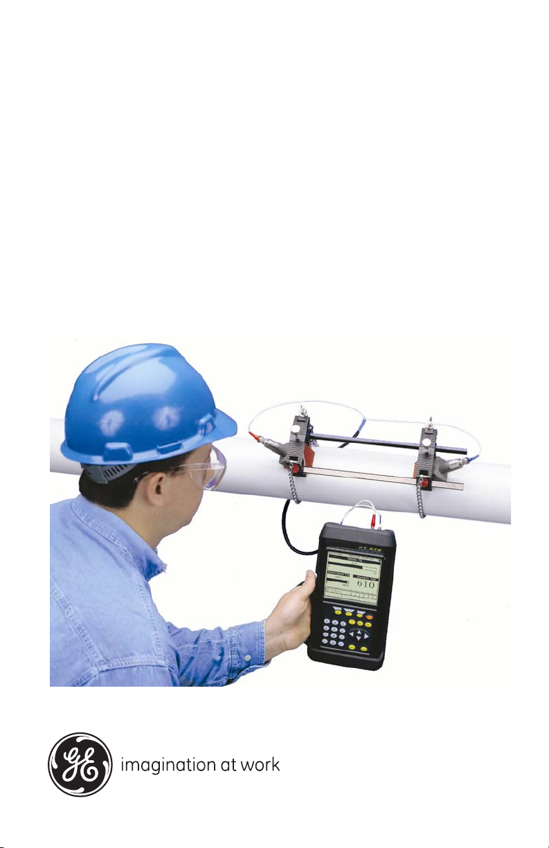
GE
Sensing & Inspection Technologies Flow
TransPort® Model PT878
Portable Liquid Flowmeter
User’s Manual
910-219 Rev. F
November 2009


GE
Sensing & Inspection Technologies
TransPort® Model PT878
Portable Liquid Flowmeter
User’s Manual
910-219 Rev. F
November 2009
GESensingInspection.com
©2009 General Electric Company. All rights reserved.
Technical content subject to change without notice.

[no content intended for this page — proceed to next page]
ii

Preface
Information Paragraphs
• Note paragraphs provide information that provides a deeper understanding of
the situation, but is not essential to the proper completion of the instructions.
• Important paragraphs provide information that emphasizes instructions that
are essential to proper setup of the equipment. Failure to follow these
instructions carefully may cause unreliable performance.
• Caution! paragraphs provide information that alerts the operator to a hazardous
situation that can cause damage to property or equipment.
• Warning! paragraphs provide information that alerts the operator to a
hazardous situation that can cause injury to personnel. Cautionary information
is also included, when applicable.
Safety Issues
WARNING! It is the responsibility of the user to make sure all local, county,
state and national codes, regulations, rules and laws related to
safety and safe operating conditions are met for each
installation.
Transport® Model PT878 Portable Liquid Flowmeter User’s Manual iii

Preface
Auxiliary Equipment
Local Safety Standards
The user must make sure that he operates all auxiliary equipment in accordance
with local codes, standards, regulations, or laws applicable to safety.
Working Area
WARNING! Auxiliary equipment may have both manual and automatic
modes of operation. As equipment can move suddenly and
without warning, do not enter the work cell of this equipment
during automatic operation, and do not enter the work
envelope of this equipment during manual operation. If you do,
serious injury can result.
WARNING! Make sure that power to the auxiliary equipment is turned OFF
and locked out before you perform maintenance procedures on
the equipment.
Qualification of Personnel
Make sure that all personnel have manufacturer-approved training applicable to the
auxiliary equipment.
Personal Safety Equipment
Make sure that operators and maintenance personnel have all safety equipment
applicable to the auxiliary equipment. Examples include safety glasses, protective
headgear, safety shoes, etc.
Unauthorized Operation
Make sure that unauthorized personnel cannot gain access to the operation of the
equipment.
iv Transport® Model PT878 Portable Liquid Flowmeter User’s Manual

Preface
Environmental Compliance
Waste Electrical and Electronic Equipment (WEEE) Directive
GE Sensing & Inspection Technologies is an active participant in Europe’s
Waste Electrical and Electronic Equipment (WEEE) take-back initiative,
directive 2002/96/EC.
The equipment that you bought has required the extraction and use of
natural resources for its production. It may contain hazardous substances
that could impact health and the environment.
In order to avoid the dissemination of those substances in our environment
and to diminish the pressure on the natural resources, we encourage you to
use the appropriate take-back systems. Those systems will reuse or recycle
most of the materials of your end life equipment in a sound way.
The crossed-out wheeled bin symbol invites you to use those systems.
If you need more information on the collection, reuse and recycling
systems, please contact your local or regional waste administration.
Visit http://www.gesensing.com/environment/weee.htm
for take-back
instructions and more information about this initiative.
Transport® Model PT878 Portable Liquid Flowmeter User’s Manual v

Preface
[no content intended for this page — proceed to next page]
vi Transport® Model PT878 Portable Liquid Flowmeter User’s Manual

Contents
Chapter 1. Features and Capabilities
1.1 Overview . . . . . . . . . . . . . . . . . . . . . . . . . . . . . . . . . . . . . . . . . . . . . . . . . . . . . . . . . . . . . . .1
1.2 System Description . . . . . . . . . . . . . . . . . . . . . . . . . . . . . . . . . . . . . . . . . . . . . . . . . . . . .2
1.2.1 The Flowcell . . . . . . . . . . . . . . . . . . . . . . . . . . . . . . . . . . . . . . . . . . . . . . . . . . . . .2
1.2.2 Electronics Package. . . . . . . . . . . . . . . . . . . . . . . . . . . . . . . . . . . . . . . . . . . . . .3
1.3 Theory of Operation . . . . . . . . . . . . . . . . . . . . . . . . . . . . . . . . . . . . . . . . . . . . . . . . . . . .4
Chapter 2. Initial Setup
2.1 Making Electrical Connections. . . . . . . . . . . . . . . . . . . . . . . . . . . . . . . . . . . . . . . . . . .6
2.1.1 Power Connections . . . . . . . . . . . . . . . . . . . . . . . . . . . . . . . . . . . . . . . . . . . . . .7
2.1.2 Transducer Connections . . . . . . . . . . . . . . . . . . . . . . . . . . . . . . . . . . . . . . . . .7
2.1.3 Input/Output Connections. . . . . . . . . . . . . . . . . . . . . . . . . . . . . . . . . . . . . . . .7
2.1.4 The Infrared Wireless Interface . . . . . . . . . . . . . . . . . . . . . . . . . . . . . . . . . . .8
2.2 Caring for the PT878 Batteries. . . . . . . . . . . . . . . . . . . . . . . . . . . . . . . . . . . . . . . . . . .9
2.2.1 Charging and Storing the Batteries . . . . . . . . . . . . . . . . . . . . . . . . . . . . . . .9
2.2.2 Replacing the Batteries. . . . . . . . . . . . . . . . . . . . . . . . . . . . . . . . . . . . . . . . . 10
2.2.3 Disposing of Batteries. . . . . . . . . . . . . . . . . . . . . . . . . . . . . . . . . . . . . . . . . . 11
2.3 Powering ON and OFF . . . . . . . . . . . . . . . . . . . . . . . . . . . . . . . . . . . . . . . . . . . . . . . . 12
2.4 Using the Screen and Keypad . . . . . . . . . . . . . . . . . . . . . . . . . . . . . . . . . . . . . . . . . 15
2.4.1 Screen. . . . . . . . . . . . . . . . . . . . . . . . . . . . . . . . . . . . . . . . . . . . . . . . . . . . . . . . . 15
2.4.2 Keypad. . . . . . . . . . . . . . . . . . . . . . . . . . . . . . . . . . . . . . . . . . . . . . . . . . . . . . . . 17
2.5 Obtaining On-Line Help . . . . . . . . . . . . . . . . . . . . . . . . . . . . . . . . . . . . . . . . . . . . . . . 19
Transport® Model PT878 Portable Liquid Flowmeter User’s Manual vii

Contents
Chapter 3. Programming Site Data
3.1 Entering the Program Menu . . . . . . . . . . . . . . . . . . . . . . . . . . . . . . . . . . . . . . . . . . . 22
3.2 Entering Transducer Parameters . . . . . . . . . . . . . . . . . . . . . . . . . . . . . . . . . . . . . . 23
3.2.1 Parameters for Special Transducers . . . . . . . . . . . . . . . . . . . . . . . . . . . . 26
3.2.2 Confirming Entries . . . . . . . . . . . . . . . . . . . . . . . . . . . . . . . . . . . . . . . . . . . . . 30
3.3 Entering Pipe Parameters . . . . . . . . . . . . . . . . . . . . . . . . . . . . . . . . . . . . . . . . . . . . . 30
3.4 Entering Pipe Lining Parameters. . . . . . . . . . . . . . . . . . . . . . . . . . . . . . . . . . . . . . . 35
3.5 Entering Fluid Types and Speeds . . . . . . . . . . . . . . . . . . . . . . . . . . . . . . . . . . . . . . 37
3.6 Entering the Signal Path Parameters. . . . . . . . . . . . . . . . . . . . . . . . . . . . . . . . . . . 39
3.6.1 Path Parameters for Clamp-On Transducers . . . . . . . . . . . . . . . . . . . . 40
3.6.2 Path Parameters for Wetted Transducers . . . . . . . . . . . . . . . . . . . . . . . 41
3.7 Entering the Energy Option Parameters. . . . . . . . . . . . . . . . . . . . . . . . . . . . . . . . 42
3.7.1 Entering Inputs in the Energy Option . . . . . . . . . . . . . . . . . . . . . . . . . . . . 44
3.7.2 Entering Custom Cp Data in the Energy Option . . . . . . . . . . . . . . . . . . 46
3.8 Entering Analog Inputs. . . . . . . . . . . . . . . . . . . . . . . . . . . . . . . . . . . . . . . . . . . . . . . . 50
3.8.1 Entering General-Purpose Analog Inputs . . . . . . . . . . . . . . . . . . . . . . . . 50
3.8.2 Entering Analog Inputs in the Energy Option. . . . . . . . . . . . . . . . . . . . . 52
3.9 Entering the Analog Output . . . . . . . . . . . . . . . . . . . . . . . . . . . . . . . . . . . . . . . . . . . 54
3.10Entering the Digital Output . . . . . . . . . . . . . . . . . . . . . . . . . . . . . . . . . . . . . . . . . . . . 57
3.11Entering User Functions. . . . . . . . . . . . . . . . . . . . . . . . . . . . . . . . . . . . . . . . . . . . . . . 61
3.11.1 Entering Correction Factors. . . . . . . . . . . . . . . . . . . . . . . . . . . . . . . . . . . . . 65
3.11.2 Entering Reynolds Correction . . . . . . . . . . . . . . . . . . . . . . . . . . . . . . . . . . . 65
3.11.3 Entering a Calibration Factor . . . . . . . . . . . . . . . . . . . . . . . . . . . . . . . . . . . 67
viii Transport® Model PT878 Portable Liquid Flowmeter User’s Manual

Contents
Chapter 4. Creating and Managing Sites
4.1 The Site Manager . . . . . . . . . . . . . . . . . . . . . . . . . . . . . . . . . . . . . . . . . . . . . . . . . . . . . 72
4.1.1 Creating a New Site . . . . . . . . . . . . . . . . . . . . . . . . . . . . . . . . . . . . . . . . . . . . 74
4.1.2 Opening an Existing Site. . . . . . . . . . . . . . . . . . . . . . . . . . . . . . . . . . . . . . . . 76
4.1.3 Saving a Site. . . . . . . . . . . . . . . . . . . . . . . . . . . . . . . . . . . . . . . . . . . . . . . . . . . 77
4.1.4 Saving a Site with a Different Name. . . . . . . . . . . . . . . . . . . . . . . . . . . . . 78
4.1.5 Refreshing a Site . . . . . . . . . . . . . . . . . . . . . . . . . . . . . . . . . . . . . . . . . . . . . . . 79
4.1.6 Renaming a Site . . . . . . . . . . . . . . . . . . . . . . . . . . . . . . . . . . . . . . . . . . . . . . . 79
4.1.7 Deleting a Site . . . . . . . . . . . . . . . . . . . . . . . . . . . . . . . . . . . . . . . . . . . . . . . . . 80
4.1.8 Creating a Site Message. . . . . . . . . . . . . . . . . . . . . . . . . . . . . . . . . . . . . . . . 81
4.1.9 Printing a Current Site . . . . . . . . . . . . . . . . . . . . . . . . . . . . . . . . . . . . . . . . . . 83
4.1.10 Transferring a Site File to a PC . . . . . . . . . . . . . . . . . . . . . . . . . . . . . . . . . . 83
4.1.11 Transferring a Site File in Text Format to a PC . . . . . . . . . . . . . . . . . . . 84
4.1.12 Transferring a File from a PC to the PT878. . . . . . . . . . . . . . . . . . . . . . . 85
4.1.13 Listing Files by Name. . . . . . . . . . . . . . . . . . . . . . . . . . . . . . . . . . . . . . . . . . . 88
4.1.14 Listing Files in Chronological Order. . . . . . . . . . . . . . . . . . . . . . . . . . . . . . 88
Chapter 5. Displaying and Configuring Data
5.1 The Format Option. . . . . . . . . . . . . . . . . . . . . . . . . . . . . . . . . . . . . . . . . . . . . . . . . . . . 90
5.2 The View Option . . . . . . . . . . . . . . . . . . . . . . . . . . . . . . . . . . . . . . . . . . . . . . . . . . . . . . 92
5.3 The Limits Option . . . . . . . . . . . . . . . . . . . . . . . . . . . . . . . . . . . . . . . . . . . . . . . . . . . . . 93
5.4 The Measurement Option . . . . . . . . . . . . . . . . . . . . . . . . . . . . . . . . . . . . . . . . . . . . . 95
5.5 Customizing the Display Screen . . . . . . . . . . . . . . . . . . . . . . . . . . . . . . . . . . . . . . . 97
5.5.1 Specifying the Number of Displayed Parameters . . . . . . . . . . . . . . . . 98
5.5.2 Customizing Softkeys . . . . . . . . . . . . . . . . . . . . . . . . . . . . . . . . . . . . . . . . . . 99
5.6 Managing Files — The Drive Manager . . . . . . . . . . . . . . . . . . . . . . . . . . . . . . . . . 102
5.6.1 Transferring a File to a PC . . . . . . . . . . . . . . . . . . . . . . . . . . . . . . . . . . . . . 104
5.6.2 Transferring a File from a PC to the PT878. . . . . . . . . . . . . . . . . . . . . . 105
5.6.3 Refreshing a File . . . . . . . . . . . . . . . . . . . . . . . . . . . . . . . . . . . . . . . . . . . . . . 107
5.6.4 Deleting a File . . . . . . . . . . . . . . . . . . . . . . . . . . . . . . . . . . . . . . . . . . . . . . . . 108
5.6.5 Listing Files by Name. . . . . . . . . . . . . . . . . . . . . . . . . . . . . . . . . . . . . . . . . . 109
5.6.6 Listing Files in Chronological Order. . . . . . . . . . . . . . . . . . . . . . . . . . . . . 109
5.7 Accessing Meter Data —The About Option . . . . . . . . . . . . . . . . . . . . . . . . . . . . 110
Transport® Model PT878 Portable Liquid Flowmeter User’s Manual ix

Contents
Chapter 6. Programming Meter Settings
6.1 Entering the Meter Menu . . . . . . . . . . . . . . . . . . . . . . . . . . . . . . . . . . . . . . . . . . . . . 112
6.2 Selecting Measurement Units . . . . . . . . . . . . . . . . . . . . . . . . . . . . . . . . . . . . . . . . 113
6.3 The Battery Charger . . . . . . . . . . . . . . . . . . . . . . . . . . . . . . . . . . . . . . . . . . . . . . . . . 114
6.4 Entering Date and Time . . . . . . . . . . . . . . . . . . . . . . . . . . . . . . . . . . . . . . . . . . . . . . 115
6.5 Changing Date and Time Appearance . . . . . . . . . . . . . . . . . . . . . . . . . . . . . . . . 117
6.6 Adjusting the Contrast . . . . . . . . . . . . . . . . . . . . . . . . . . . . . . . . . . . . . . . . . . . . . . . 120
6.7 Setting Backlight Timeout . . . . . . . . . . . . . . . . . . . . . . . . . . . . . . . . . . . . . . . . . . . . 121
6.8 Changing the Display Language. . . . . . . . . . . . . . . . . . . . . . . . . . . . . . . . . . . . . . 122
6.9 Changing Communications Settings . . . . . . . . . . . . . . . . . . . . . . . . . . . . . . . . . . 123
6.10Resetting Forward and Reverse Totals . . . . . . . . . . . . . . . . . . . . . . . . . . . . . . . . 126
6.11Setting Up User Tables . . . . . . . . . . . . . . . . . . . . . . . . . . . . . . . . . . . . . . . . . . . . . . . 127
6.12Taking a Bitmap Capture of a Current Screen . . . . . . . . . . . . . . . . . . . . . . . . . 130
x Transport® Model PT878 Portable Liquid Flowmeter User’s Manual

Contents
Chapter 7. Logging Data
7.1 Entering the Logging Menu. . . . . . . . . . . . . . . . . . . . . . . . . . . . . . . . . . . . . . . . . . . 132
7.2 The Log Manager . . . . . . . . . . . . . . . . . . . . . . . . . . . . . . . . . . . . . . . . . . . . . . . . . . . . 133
7.3 The File Menu. . . . . . . . . . . . . . . . . . . . . . . . . . . . . . . . . . . . . . . . . . . . . . . . . . . . . . . . 134
7.3.1 Setting up a New Log . . . . . . . . . . . . . . . . . . . . . . . . . . . . . . . . . . . . . . . . . 135
7.3.2 Copying (Cloning) a Selected Log . . . . . . . . . . . . . . . . . . . . . . . . . . . . . . 140
7.3.3 Renaming a Log . . . . . . . . . . . . . . . . . . . . . . . . . . . . . . . . . . . . . . . . . . . . . . 141
7.3.4 Deleting a Log . . . . . . . . . . . . . . . . . . . . . . . . . . . . . . . . . . . . . . . . . . . . . . . . 141
7.3.5 Deleting All Logs . . . . . . . . . . . . . . . . . . . . . . . . . . . . . . . . . . . . . . . . . . . . . . 142
7.3.6 Refreshing the Log Manager Screen . . . . . . . . . . . . . . . . . . . . . . . . . . . 142
7.3.7 Printing a Log. . . . . . . . . . . . . . . . . . . . . . . . . . . . . . . . . . . . . . . . . . . . . . . . . 143
7.3.8 Transferring a Log to a PC. . . . . . . . . . . . . . . . . . . . . . . . . . . . . . . . . . . . . 144
7.4 The Log Menu . . . . . . . . . . . . . . . . . . . . . . . . . . . . . . . . . . . . . . . . . . . . . . . . . . . . . . . 145
7.4.1 Stopping (Pausing) a Log . . . . . . . . . . . . . . . . . . . . . . . . . . . . . . . . . . . . . . 146
7.4.2 Restarting a Log . . . . . . . . . . . . . . . . . . . . . . . . . . . . . . . . . . . . . . . . . . . . . . 146
7.4.3 Ending a Log. . . . . . . . . . . . . . . . . . . . . . . . . . . . . . . . . . . . . . . . . . . . . . . . . . 146
7.4.4 Stopping All Logs. . . . . . . . . . . . . . . . . . . . . . . . . . . . . . . . . . . . . . . . . . . . . . 147
7.4.5 Restarting All Logs . . . . . . . . . . . . . . . . . . . . . . . . . . . . . . . . . . . . . . . . . . . . 147
7.4.6 Ending All Logs . . . . . . . . . . . . . . . . . . . . . . . . . . . . . . . . . . . . . . . . . . . . . . . 147
7.4.7 View All Sites . . . . . . . . . . . . . . . . . . . . . . . . . . . . . . . . . . . . . . . . . . . . . . . . . 147
7.5 The View Menu . . . . . . . . . . . . . . . . . . . . . . . . . . . . . . . . . . . . . . . . . . . . . . . . . . . . . . 148
7.5.1 Displaying Log Details. . . . . . . . . . . . . . . . . . . . . . . . . . . . . . . . . . . . . . . . . 149
7.5.2 Displaying Log Data in Graphical Form. . . . . . . . . . . . . . . . . . . . . . . . . 150
7.5.3 Displaying Log Data in Spreadsheet Form . . . . . . . . . . . . . . . . . . . . . . 153
7.6 The Sort Menu . . . . . . . . . . . . . . . . . . . . . . . . . . . . . . . . . . . . . . . . . . . . . . . . . . . . . . . 154
7.6.1 Listing Logs by Name . . . . . . . . . . . . . . . . . . . . . . . . . . . . . . . . . . . . . . . . . 154
7.6.2 Listing Logs in Chronological Order . . . . . . . . . . . . . . . . . . . . . . . . . . . . 154
Transport® Model PT878 Portable Liquid Flowmeter User’s Manual xi

Contents
Chapter 8. Servicing the PT878
8.1 Entering the Service Menu . . . . . . . . . . . . . . . . . . . . . . . . . . . . . . . . . . . . . . . . . . . 156
8.2 Printing Reports . . . . . . . . . . . . . . . . . . . . . . . . . . . . . . . . . . . . . . . . . . . . . . . . . . . . . 157
8.3 Setting up the Thickness Gauge . . . . . . . . . . . . . . . . . . . . . . . . . . . . . . . . . . . . . . 159
8.4 Measuring Pipe Wall Thickness . . . . . . . . . . . . . . . . . . . . . . . . . . . . . . . . . . . . . . . 160
8.4.1 Entering the Material and Soundspeed. . . . . . . . . . . . . . . . . . . . . . . . . 160
8.4.2 Measuring Thickness in Numeric Format . . . . . . . . . . . . . . . . . . . . . . . 162
8.4.3 Displaying the Receive Signal in Graphical Format . . . . . . . . . . . . . . 163
8.4.4 Calibrating the Thickness Gauge Transducer . . . . . . . . . . . . . . . . . . . 165
8.4.5 Calculating Velocity (Pipe Material Soundspeed) . . . . . . . . . . . . . . . . 168
8.5 Programming the Thickness Gauge. . . . . . . . . . . . . . . . . . . . . . . . . . . . . . . . . . . 170
8.6 Displaying Diagnostic Parameters . . . . . . . . . . . . . . . . . . . . . . . . . . . . . . . . . . . . 173
8.7 Calibrating the Analog Output and Inputs . . . . . . . . . . . . . . . . . . . . . . . . . . . . . 174
8.7.1 Calibrating the Analog Output . . . . . . . . . . . . . . . . . . . . . . . . . . . . . . . . . 174
8.7.2 Calibrating Inputs . . . . . . . . . . . . . . . . . . . . . . . . . . . . . . . . . . . . . . . . . . . . . 176
8.8 Setting up Signal Parameters. . . . . . . . . . . . . . . . . . . . . . . . . . . . . . . . . . . . . . . . . 178
8.8.1 Setting up Signal Parameters . . . . . . . . . . . . . . . . . . . . . . . . . . . . . . . . . . 179
8.8.2 Setting up Peak Detection . . . . . . . . . . . . . . . . . . . . . . . . . . . . . . . . . . . . . 181
8.8.3 Selecting the Transmit Code. . . . . . . . . . . . . . . . . . . . . . . . . . . . . . . . . . . 183
8.9 Setting Error Limits. . . . . . . . . . . . . . . . . . . . . . . . . . . . . . . . . . . . . . . . . . . . . . . . . . . 184
8.10The Test Option . . . . . . . . . . . . . . . . . . . . . . . . . . . . . . . . . . . . . . . . . . . . . . . . . . . . . . 187
8.10.1 Testing the Screen . . . . . . . . . . . . . . . . . . . . . . . . . . . . . . . . . . . . . . . . . . . . 188
8.10.2 Testing the Keys . . . . . . . . . . . . . . . . . . . . . . . . . . . . . . . . . . . . . . . . . . . . . . 189
8.10.3 Testing the Watchdog Timer Circuit. . . . . . . . . . . . . . . . . . . . . . . . . . . . 190
8.10.4 Setting Impulse Response . . . . . . . . . . . . . . . . . . . . . . . . . . . . . . . . . . . . . 191
8.10.5 Taking Wave Samples for Diagnosis . . . . . . . . . . . . . . . . . . . . . . . . . . . 192
8.10.6 Applying a Stored Signal for Diagnosis . . . . . . . . . . . . . . . . . . . . . . . . . 192
8.10.7 Testing the Battery . . . . . . . . . . . . . . . . . . . . . . . . . . . . . . . . . . . . . . . . . . . . 193
8.11Resetting to Factory Default Parameters. . . . . . . . . . . . . . . . . . . . . . . . . . . . . . 194
8.12Updating PT878 Software . . . . . . . . . . . . . . . . . . . . . . . . . . . . . . . . . . . . . . . . . . . . 195
8.12.1 Updating Software Via IrOBEX . . . . . . . . . . . . . . . . . . . . . . . . . . . . . . . . . 196
8.12.2 Updating Software Via IrCOMM . . . . . . . . . . . . . . . . . . . . . . . . . . . . . . . . 197
xii Transport® Model PT878 Portable Liquid Flowmeter User’s Manual

Contents
Chapter 9. Diagnostics and Troubleshooting
9.1 Error Code Messages . . . . . . . . . . . . . . . . . . . . . . . . . . . . . . . . . . . . . . . . . . . . . . . . 204
9.2 Displaying Diagnostic Parameters . . . . . . . . . . . . . . . . . . . . . . . . . . . . . . . . . . . . 206
9.3 Flowcell Problems . . . . . . . . . . . . . . . . . . . . . . . . . . . . . . . . . . . . . . . . . . . . . . . . . . . 208
9.3.1 Fluid Problems . . . . . . . . . . . . . . . . . . . . . . . . . . . . . . . . . . . . . . . . . . . . . . . . 208
9.3.2 Pipe Problems . . . . . . . . . . . . . . . . . . . . . . . . . . . . . . . . . . . . . . . . . . . . . . . . 209
9.4 Transducer Problems . . . . . . . . . . . . . . . . . . . . . . . . . . . . . . . . . . . . . . . . . . . . . . . . 210
9.4.1 Wetted Transducer Problems. . . . . . . . . . . . . . . . . . . . . . . . . . . . . . . . . . 210
9.4.2 Clamp-on Transducer Problems . . . . . . . . . . . . . . . . . . . . . . . . . . . . . . . 211
9.4.3 Relocating Transducers . . . . . . . . . . . . . . . . . . . . . . . . . . . . . . . . . . . . . . . 212
Chapter 10. Specifications
10.1Overall . . . . . . . . . . . . . . . . . . . . . . . . . . . . . . . . . . . . . . . . . . . . . . . . . . . . . . . . . . . . . . 213
10.1.1 Hardware Configuration . . . . . . . . . . . . . . . . . . . . . . . . . . . . . . . . . . . . . . 213
10.1.2 Size/Weight. . . . . . . . . . . . . . . . . . . . . . . . . . . . . . . . . . . . . . . . . . . . . . . . . . . 213
10.1.3 Enclosure. . . . . . . . . . . . . . . . . . . . . . . . . . . . . . . . . . . . . . . . . . . . . . . . . . . . . 213
10.1.4 Flow Accuracy (Velocity, % of reading): . . . . . . . . . . . . . . . . . . . . . . . . . 213
10.2Electrical . . . . . . . . . . . . . . . . . . . . . . . . . . . . . . . . . . . . . . . . . . . . . . . . . . . . . . . . . . . . 214
10.3Operational Specifications . . . . . . . . . . . . . . . . . . . . . . . . . . . . . . . . . . . . . . . . . . . 216
10.4Transducer . . . . . . . . . . . . . . . . . . . . . . . . . . . . . . . . . . . . . . . . . . . . . . . . . . . . . . . . . . 217
10.4.1 Clamp-On Ultrasonic Flow Transducers . . . . . . . . . . . . . . . . . . . . . . . . 217
10.4.2 Temperature Transducers . . . . . . . . . . . . . . . . . . . . . . . . . . . . . . . . . . . . . 217
10.5Pipe Size and Material . . . . . . . . . . . . . . . . . . . . . . . . . . . . . . . . . . . . . . . . . . . . . . . 217
10.5.1 Clamp-On Transducers: . . . . . . . . . . . . . . . . . . . . . . . . . . . . . . . . . . . . . . . 217
10.6Available Options . . . . . . . . . . . . . . . . . . . . . . . . . . . . . . . . . . . . . . . . . . . . . . . . . . . . 218
Transport® Model PT878 Portable Liquid Flowmeter User’s Manual xiii

Contents
Appendix A. Menu Maps
Appendix B. Measuring P and L Dimensions
Appendix C. Temperature Transmitter Installation
C.1 Guidelines for RTD Installation. . . . . . . . . . . . . . . . . . . . . . . . . . . . . . . . . . . . . . . . 243
C.2 Mounting RTDs on the Pipe . . . . . . . . . . . . . . . . . . . . . . . . . . . . . . . . . . . . . . . . . . . 244
C.2.1 Assembling the Clamping Fixture . . . . . . . . . . . . . . . . . . . . . . . . . . . . . . 244
C.2.2 Mounting the RTD to the Pipe . . . . . . . . . . . . . . . . . . . . . . . . . . . . . . . . . . 245
C.3 Making Electrical Connections. . . . . . . . . . . . . . . . . . . . . . . . . . . . . . . . . . . . . . . . 245
C.3.1 Connecting the RTD to the 4 to 20-mA Transmitter . . . . . . . . . . . . . 246
C.3.2 Connecting the Transmitter to the PT878. . . . . . . . . . . . . . . . . . . . . . . 247
Appendix D. Ultrasonic Thickness Gauge Theory of Operation
D.1 Factors Affecting Performance and Accuracy . . . . . . . . . . . . . . . . . . . . . . . . . 250
D.1.1 Transducer Positioning/Alignment . . . . . . . . . . . . . . . . . . . . . . . . . . . . . 251
D.1.2 Calibration. . . . . . . . . . . . . . . . . . . . . . . . . . . . . . . . . . . . . . . . . . . . . . . . . . . . 252
D.1.3 Taper or Eccentricity . . . . . . . . . . . . . . . . . . . . . . . . . . . . . . . . . . . . . . . . . . 252
D.1.4 Acoustic Properties of the Material . . . . . . . . . . . . . . . . . . . . . . . . . . . . . 252
Appendix E. Material Safety Data Sheet for Couplant
E.1 Product Identification . . . . . . . . . . . . . . . . . . . . . . . . . . . . . . . . . . . . . . . . . . . . . . . . 253
E.2 Hazardous Ingredients . . . . . . . . . . . . . . . . . . . . . . . . . . . . . . . . . . . . . . . . . . . . . . . 253
E.3 Physical Data (nominal) . . . . . . . . . . . . . . . . . . . . . . . . . . . . . . . . . . . . . . . . . . . . . . 254
E.4 Fire and Explosion Hazard Data . . . . . . . . . . . . . . . . . . . . . . . . . . . . . . . . . . . . . . 254
E.5 Reactivity Data . . . . . . . . . . . . . . . . . . . . . . . . . . . . . . . . . . . . . . . . . . . . . . . . . . . . . . 254
E.6 Health Hazard and First Aid Data . . . . . . . . . . . . . . . . . . . . . . . . . . . . . . . . . . . . . 255
E.7 Storage and Handling Information. . . . . . . . . . . . . . . . . . . . . . . . . . . . . . . . . . . . 255
E.8 Control Measures . . . . . . . . . . . . . . . . . . . . . . . . . . . . . . . . . . . . . . . . . . . . . . . . . . . . 256
Appendix F. Establishing IR Communications
Appendix G. Glossary
xiv Transport® Model PT878 Portable Liquid Flowmeter User’s Manual

Chapter 1. Features and Capabilities
Chapter 1. Features and Capabilities
The TransPort® Model PT878 is a transit-time flowmeter which combines
all the features of a full-size flowmeter with the advantages of a portable
instrument.
This section describes the TransPort features and general system, and
explains the theory of operation.
1.1 Overview
The PT878 measures the flow rate of acoustically conductive single-phase
fluids. This includes most clean liquids, sewage, some slurries, some
oil/water mixtures, and liquids with a small percentage of entrained gas
bubbles. The flowmeter provides one linear (0/4-20 mA) analog output of
flow velocities or volumetric flow rate of these fluids, measuring velocities
from ±0.03 to ±12 m/sec (±0.1 to ±40 ft/sec), along with one selectable
frequency output or pulsed totalizer output.
The PT878 also provides two 4 to 20-mA analog inputs in order to connect
temperature transmitters to measure energy flow rate of liquids. Energy
flow rate may be calculated for water, glycol, and water/glycol mixtures.
The PT878 has the ability to store site data in files which can be accessed at
a later time. Within the Main Menu, a set of forms (windows) asks you all
the necessary setup information for a particular site. Once the necessary
questions are answered, you simply save the information to a file.
The PT878 stores these files and other data in non-volatile memory, which
retains the information even if power is off. The flowmeter itself runs on
rechargeable or alkaline batteries for up to 10 hours.
This small lightweight flowmeter displays measurements in both numeric
and graphical form on a EL-backlit, 240 x 200 pixel LCD graphic screen.
The PT878 also has the capability of logging over 100,000 flow data points
internally.
Using an infrared communications port, the PT878 can transmit or print
logged data, as well as real time data and other stored data. It is also
computer-programmable via GE’s PanaView™ software.
Transport® Model PT878 Portable Liquid Flowmeter User’s Manual 1

Chapter 1. Features and Capabilities
1.1 Overview (cont.)
To assist you, the PT878 is fully equipped with context-sensitive on-line
help which is accessible at any time by simply pressing the “?” (Help) key.
Internal diagnostic and troubleshooting features help is olate and remedy
common flowcell and transducer problems.
The PT878 operates with all standard GE transducers — wetted, clamp-on,
®
hybrids (Pan-Adapta
plug), and buffered styles.
A built-in ultrasonic thickness gauge capability measures the pipe wall
thickness when used with the optional thickness transducer.
1.2 System Description
The PT878 is one part of the flowmeter system. The flowmeter system
consists of two essential subsystems: the flowcell and the electronics
package (the PT878).
1.2.1 The Flowcell
The flowcell is that part of the system that uses ultrasonic pulses to
interrogate the flow. It consists of the flowcell pipe and the transducers.
A. FLOWCELL PIPE — The flowcell can either be created in the existing
piping (for example, by inserting wetted transducers into the pipe, or
clamping non-wetted transducers onto the pipe), or inserted as a
substitute pipe section (spoolpiece). The flowcell must provide
mechanical support for the transducers and assure stable fluid conditions
for accurate flow measurement.
B. TRANSDUCERS — The transducers convert electrical energy into
ultrasonic pulses when in a transmit cycle, and convert the ultrasonic
pulses back to electrical energy when in a receive cycle. In other words,
they act like loudspeakers when transmitting the signal and microphones
when receiving it. In the PT878 system, each transducer acts as both a
receiver and transmitter, since a series of ultrasonic pulses are alternately
sent upstream and then downstream through the flowcell.
2 Transport® Model PT878 Portable Liquid Flowmeter User’s Manual

Chapter 1. Features and Capabilities
1.2.2 Electronics Package
The PT878 consists of circuits that generate, receive, and measure the travel
time of the ultrasonic pulses. It also contains a microcomputer that controls
operation and calculates flow measurement parameters. Specific circuits
function as follows:
• TRANSMIT SIGNAL GENERATOR — The transmit signal generator,
under control of the microcomputer and timing circuit, synthesizes the
signal that drives the transmitter.
• TRANSMITTER — The transmitter amplifies the signals from the
transmit signal generator to a signal that drives the transmit transducer.
• RECEIVER — The receiver amplifies the received signals to a level
suitable for the data acquisition circuitry.
• DATA ACQUISITION — The data acquisition circuitry digitizes the
received signal and stores it in a buffer for processing by the
microcomputer.
• TIMING CIRCUIT — The timing circuit generates the transmitter
frequency, receive window, controls the data acquisition circuit and the
direction of the transmission.
• MICROCOMPUTER — The microcomputer controls the PT878
flowmeter’s operation and calculates flow measurements derived from
the transmitted and digitized received signals. Also, the microcomputer
continually checks for faults and allows the use of built-in diagnostics for
troubleshooting.
• INPUT/OUTPUT — The input/output circuitry allows the flowmeter to
indicate the measured flow with the 0/4-20 mA current loop, and to
output to a printer or other remote device. The digital output supports
frequency or pulse output, as well as use as a gate input; it can also act as
a test point for triggering an oscilloscope from the transmit or receive
window.
Transport® Model PT878 Portable Liquid Flowmeter User’s Manual 3

Chapter 1. Features and Capabilities
1.3 Theory of Operation
The PT878 is a transit-time ultrasonic flowmeter. When ultrasonic pulses
are transmitted through a moving liquid, the pulses that travel in the same
direction as the fluid flow (downstream) travel slightly faster than the pulses
that travel against the flow (upstream). The PT878 uses various digital
signal processing techniques, including cross-correlation, to determine
transit times and then uses the transit times to calculate flow velocity.
During operation, two transducers serve as both ultrasonic signal generators
and receivers. When mounted on a pipe, they are in acoustic communication
with each other, so that each transducer can receive ultrasonic signals
transmitted by the other transducer. Each transducer thus functions as a
transmitter generating a certain number of acoustic pulses, and as a receiver
for an identical number of pulses.
The flowmeter measures the time interval between transmission and
reception of the ultrasonic signals in both directions. When the liquid in the
pipe is not flowing, the transit-time downstream equals the transit-time
upstream. When the liquid is flowing, the transit-time downstream is less
than the transit-time upstream. The difference between the downstream and
upstream transit-times is proportional to the velocity of the flowing liquid,
and its sign indicates the direction of flow.
4 Transport® Model PT878 Portable Liquid Flowmeter User’s Manual
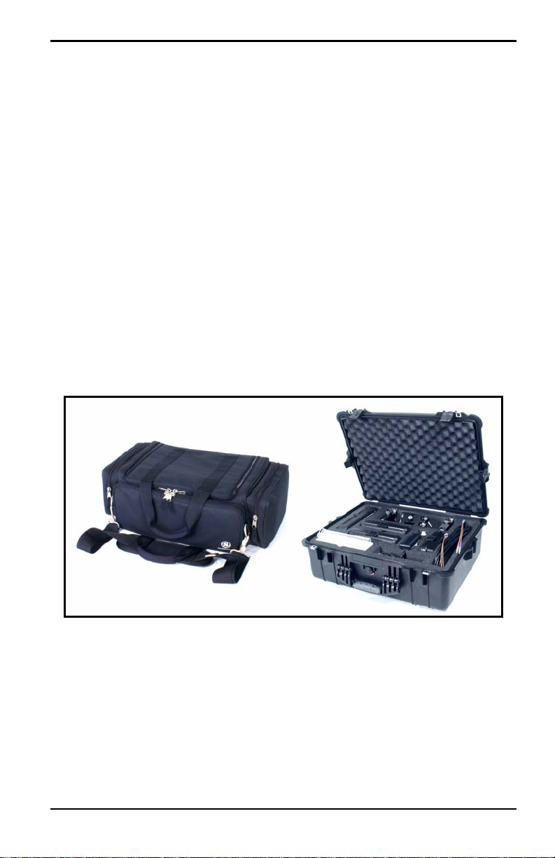
Chapter 2. Initial Setup
Chapter 2. Initial Setup
Before making measurements, you must prepare the PT878 for operation.
This includes the following procedures:
• Making Electrical Connections
• Charging and/or Replacing Batteries
• Powering On and Off
• Using the Screen and Keypad
• Obtaining On-Line Help
Figure 1 below shows the PT878 in its standard soft case (a) and in the
optional solid case (b). In the solid case, the interior is structured for optimal
protection of the PT878 and its accessories.
(a) (b)
Figure 1: The PT878 and Accessories
Transport® Model PT878 Portable Liquid Flowmeter User’s Manual 5
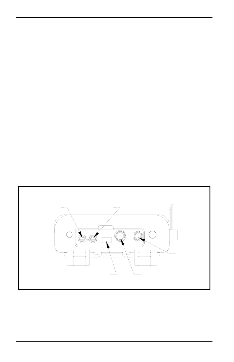
Chapter 2. Initial Setup
2.1 Making Electrical Connections
Before making measurements with the PT878, you must make all the
necessary connections to the unit. This section describes how to connect the
following:
• Power
• Transducers
• Input/Output
• Infrared Interface
Make all connections to the top of the PT878 unit as shown in Figure 2
below. Please note that you need to make the proper power and transducer
connections only. The other connections are required for particular
functions, but are not necessary for basic operation.
Note: For a listing of Input/Output connections, see Table 1 on page 8.
Transducer
Upstream
Infrared Transceiver
Downstream
Power
Input/Output
Figure 2: Connection Locations
6 Transport® Model PT878 Portable Liquid Flowmeter User’s Manual

Chapter 2. Initial Setup
2.1.1 Power Connections
The PT878 is powered by either a 100-120/200-260 VAC wall mount
plug-in module, or by 5 internal C
-size NiCad high-energy rechargeable
s
batteries or by a pack of 3.0 Ahr NiMH batteries. (An optional power
supplement, part #703-1283, uses 6 AA alkaline batteries.) When you
receive the PT878, the batteries are not charged; therefore, to make remote
measurements using the batteries, follow the instructions on page 9 to
charge the batteries. In either case, you must connect the power cord to the
appropriate terminal as shown in Figure 2 on page 6.
WARNING! To ensure the safe operation of the PT878, you must
install and operate it as described in this manual. In
addition, be sure to follow all applicable safety codes and
regulations for installing electrical equipment in your
area. The PT878 and its transducers are designed for use
only in general-purpose locations.
2.1.2 Transducer Connections
The transducer cables connect to the PT878 with LEMO® coaxial type
connectors. Each color-coded cable should have a collar labeled
UPSTREAM or DOWNSTREAM. Make transducer cable connections to
the top of the flowmeter as shown in Figure 2 on page 6. Because there are
various types of transducers and installations, transducer installation is
discussed separately in the Liquid Transducer Installation Guide (916-055).
2.1.3 Input/Output Connections
The PT878 provides one 0/4-20 mA current output and two 4 to 20-mA
analog inputs with switchable 16-V supply for loop- powered temperature
transmitters. It also supports digital, frequency, and totalizer outputs.
Connect the inputs/outputs using a LEMO
Figure 2 on page 6. The pin numbers for the connector and the color code
for the standard input/output cable are shown in Table 1 on page 8.
Transport® Model PT878 Portable Liquid Flowmeter User’s Manual 7
®
multi-pin connector as in

Chapter 2. Initial Setup
2.1.3 Input/Output Connections (cont.)
Table 1: Cable Assembly for Analog Inputs/Outputs
Pin
Number
Wire
Color Description
1 Black Analog Out 1
2 Red 16 V (switched)
3 White Supply or Return Temperature (Input A)
4 Yellow Supply or Return Temperature (Input B)
5 Green Analog Ground
6 Orange Digital Output (frequency output, pulse totalizer,
diagnostic output or calibration gate)
7 Blue Digital Ground
8 Violet Receive Monitor
2.1.4 The Infrared Wireless Interface
The PT878 comes equipped with an internal infrared transceiver (shown in
Figure 2 on page 6) that enables communication between the meter and
other IR devices, particularly the IR ports or dongles (IR to RS232 adapters)
of Windows
They can also program the meter using the optional PanaView software
interface. The PT878 was designed for use with products that comply to the
IrDA protocol. For more information on establishing IR communications
between the PT878 and your PC, refer to Appendix F.
®
-based PCs. Users can send and receive site and log data.
Note: The dongle connection is RS232. The configuration options are either
RS232 or IRDa. Selecting the RS232 does not
link the meter to the
dongle. IrDa must be selected for the link to work.
• To transfer files between the PT878 and PC, see Managing Files — the
Drive Manager on page 102.
• To transfer a log from the PT878 to a PC, see page 144.
8 Transport® Model PT878 Portable Liquid Flowmeter User’s Manual

Chapter 2. Initial Setup
2.2 Caring for the PT878 Batteries
The PT878 comes with self-contained, built-in rechargeable batteries to
support portable operation. For optimum performance, these batteries
require a minimum of maintenance.
CAUTION! Use only GE-approved batteries and desktop chargers.
These chargers are designed to maximize battery life.
Using other batteries or chargers voids the warranty and
may cause damage.
IMPORTANT: For CE compliance, the PT878 is classified as a
battery-powered device, not to be used with the AC
adaptor.
2.2.1 Charging and Storing the Batteries
When you receive the PT878, you will need to initially charge the batteries.
Also, the battery may need recharging if it has not been used for a long
period of time. The batteries must be charged up to 8 hours to receive the
maximum charge. When fully charged, the batteries provide 8 to 10 hours
of continuous operation. An internal battery gauge indicates the remaining
power in the batteries.
To charge the batteries, simply plug the AC power module cord into the
power jack (shown in Figure 2 on page 6) and be sure the battery pack is
installed. When the PT878 is plugged into line voltage, the internal battery
charger automatically charges the batteries, whether the PT878 is on or off.
If the PT878 is on, the Battery icon in the upper right corner of the screen
indicates battery status (as shown in Table 2 on page 10).
Note: For version 1B of the PT878 software, you must also press the red
power key in the upper right corner of the keypad. (See page 110 to
determine your software version.)
For optimal run time, charge the batteries only in temperatures from 50°F to
104°F (10°C to 40°C). Otherwise, the batteries will not be properly charged
and will have a significantly reduced run time.
Transport® Model PT878 Portable Liquid Flowmeter User’s Manual 9
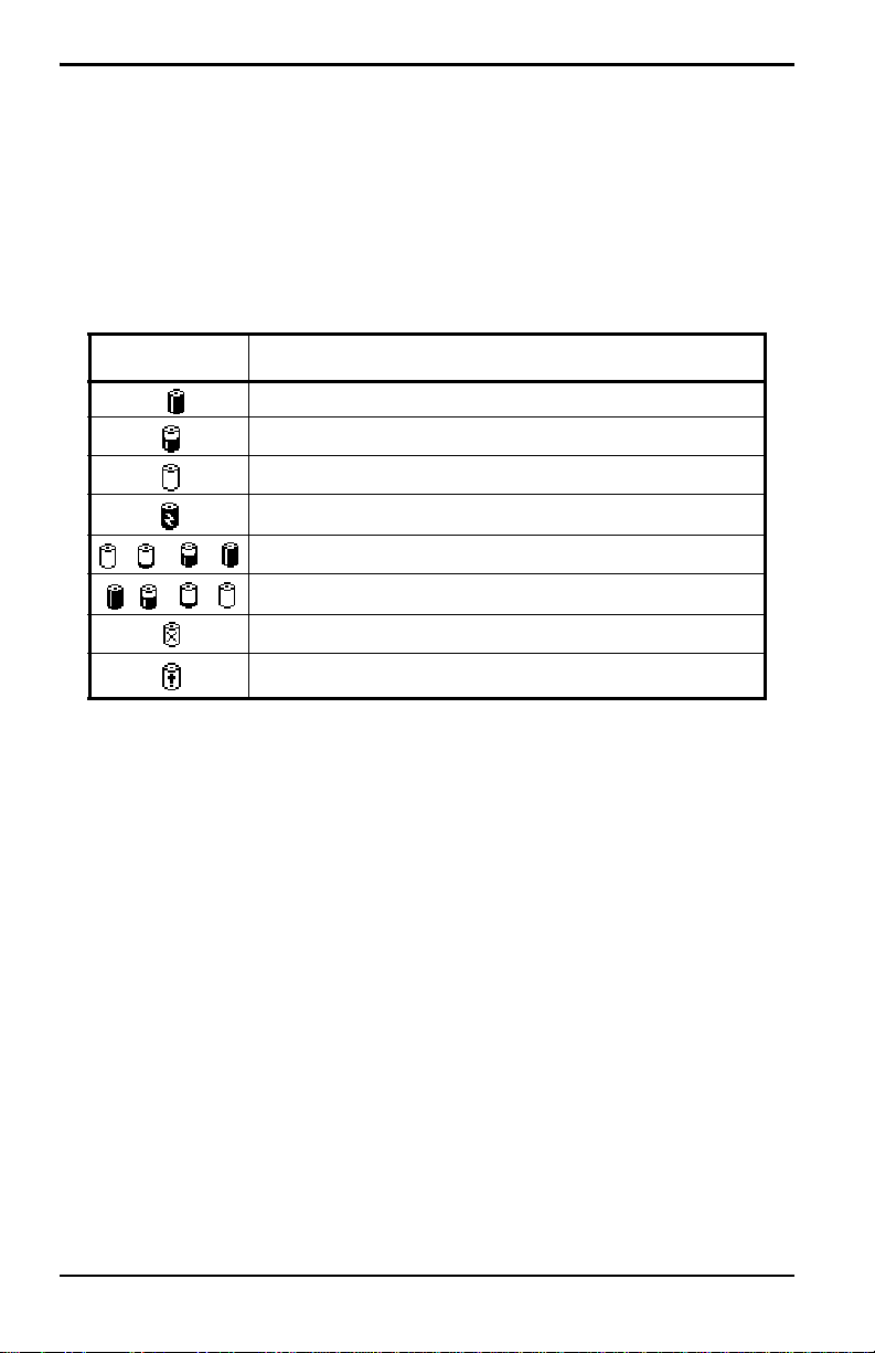
Chapter 2. Initial Setup
2.2.1 Charging and Storing the Batteries (cont.)
Store the batteries at temperatures from –4°F to 131°F (–20°C to 55°C) for
periods of less than one month, or from 32°F to 104°F (0°C to 40°C) for
longer periods. (If you are transporting them for two days or less, the
batteries can withstand temperatures from –40°F to 158°F (–40°C to 70°C).
Table 2: Battery Status Icons
Icon Battery Status
Full battery
Partially full battery
Empty battery
Fully charged battery, connected to AC power
Charging battery
Discharging battery
Failure/missing battery
Notification to check battery form (see page 114)
2.2.2 Replacing the Batteries
CAUTION! Replace batteries only with the specified rechargeable
batteries. The battery charges when the unit is off. Do not
attempt to recharge non-rechargeable batteries.
If you need to replace the rechargeable batteries, use the recommended 3.0
Ahr NiMH batteries (part number 200-081). While the batteries can be
recharged up to 600 times, it is best to replace them when they no longer
provide acceptable performance. T o replace the batteries, remove the rubber
boot, open the panel located on the back of the PT878 unit, disconnect the
batteries, and replace with new ones (see Figure 3 on page 11).
10 Transport® Model PT878 Portable Liquid Flowmeter User’s Manual
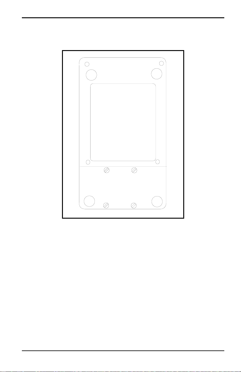
2.2.2 Replacing the Batteries (cont.)
Battery Location
(behind panel)
Chapter 2. Initial Setup
Figure 3: Battery Location
To further extend the battery power on the PT878, the GE Part #705-1283
option uses 6 AA alkaline batteries.
2.2.3 Disposing of Batteries
CAUTION! Never dispose of the batteries by incineration. Do not
attempt to disassemble or short-circuit the batteries. For
safety. do not handle a damaged or leaking battery.
IMPORTANT: Be sure to dispose of your battery properly. In some areas,
battery disposal in business or household trash may be
prohibited. For safe disposal options, contact your nearest
GE-authorized service center.
Transport® Model PT878 Portable Liquid Flowmeter User’s Manual 11

Chapter 2. Initial Setup
2.3 Powering ON and OFF
To operate the PT878, the power cord must be plugged into line voltage or
the battery must be charged as described previously.
IMPORTANT: For CE compliance, the PT878 is classified as a
battery-powered device, not to be used with the AC adapter.
To comply with CE certification, do not operate the meter
with the charger plugged in.
T o turn the PT878 on, press the red button in the upper-right-hand corner of
the keypad. Immediately upon power up the PT878 emits a short beep and
displays a “PCI Loader” message. It then validates the instrument
programming, and then displays the GE logo and the software version and
emits a long beep. If the meter fails any of these tests, contact the factory.
WARNING! If the meter fails the backup battery test, you must send
the unit back to the factory for a battery replacement.
Make sure you keep the batteries charged until you are
ready to ship the unit back to the factory. Before shipping,
print out all the log and site data, or transfer it to your PC.
12 Transport® Model PT878 Portable Liquid Flowmeter User’s Manual
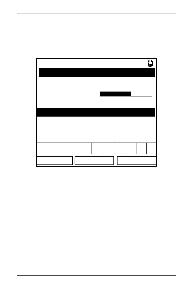
Chapter 2. Initial Setup
2.3 Powering ON and OFF (cont.)
After the meter conducts all the self checks, the screen then appears similar
to the one shown in Figure 4 below.
ABC.SIT
Velocity, ft/s
0.00
Delta-T, ns
E0: No Errors
Figure 4: Screen After Powering ON
0.10
2000/11/30 09:53 AM
Signal, dB
32
Volume, l/s
0.0
Transport® Model PT878 Portable Liquid Flowmeter User’s Manual 13
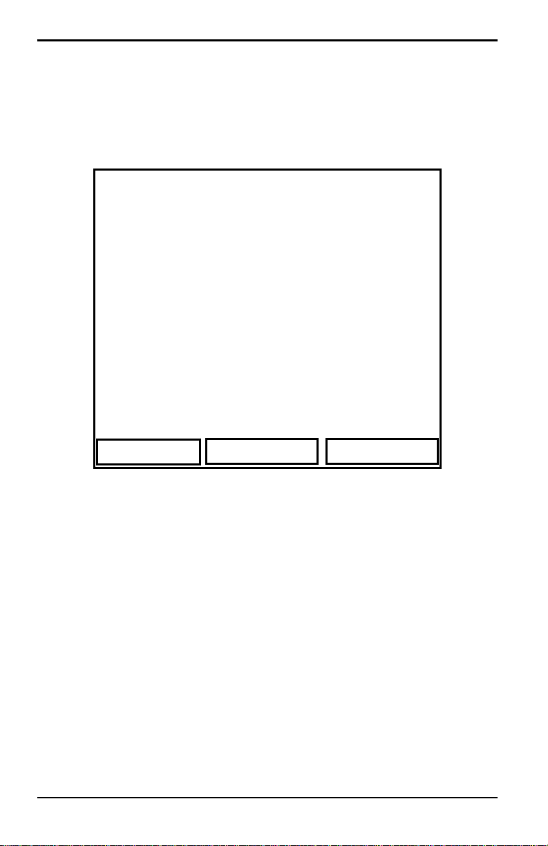
Chapter 2. Initial Setup
2.3 Powering ON and OFF (cont.)
To turn the PT878 off, press the red key for 3 seconds. The screen now
appears similar to Figure 5 below.
Velocity, ft/s
SHUTDOWN: Meter OFF
Signal, dB
SLEEP: Meter Idle
CANCEL: Resume Operations
Delta-T, ns
Shutdown
Figure 5: Shutdown Menu
Three options are available:
Sleep
Volume, l/s
Resume
• Press [F1] to shut down the PT878, turning it completely off.
• Press [F2] to send the PT878 into sleep mode. In this mode, some of the
power supplies shut down, but the PT878 remains in a standby mode.
Users can resume taking measurements immediately by pressing the
power button.
• Press [F3] to cancel the command and return the PT878 to normal
operation.
If the PT878 locks up, you can reset it by holding the power key (the red key
in the upper right corner) for 15 seconds.
14 Transport® Model PT878 Portable Liquid Flowmeter User’s Manual
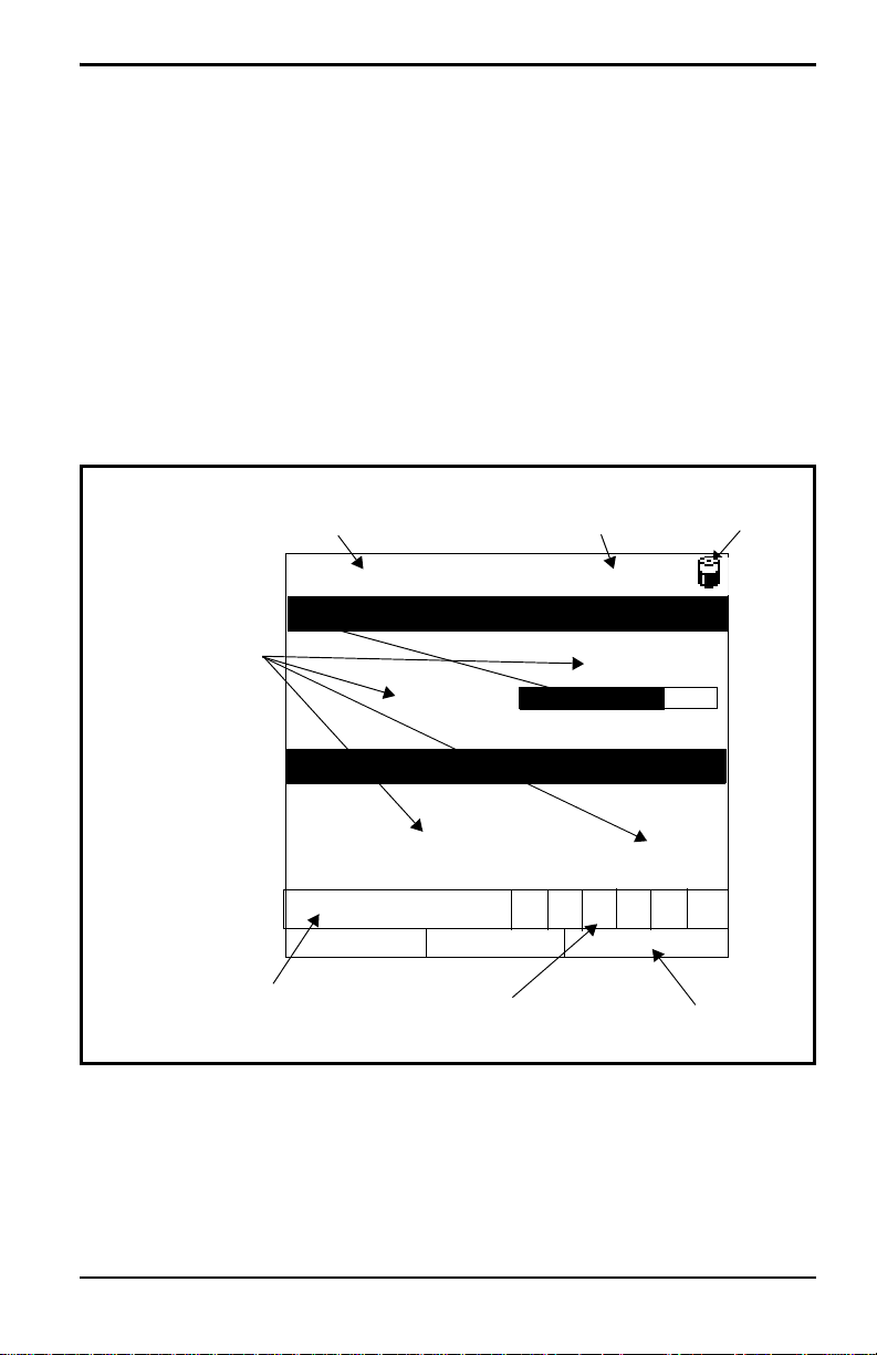
Chapter 2. Initial Setup
2.4 Using the Screen and Keypad
The essential features for operating the PT878 are the screen and keypad.
Although these features are common on portable instruments, the PT878
design offers particular features to simplify and speed operation.
2.4.1 Screen
The primary function of the screen is to display information in order for you
to accurately and easily take measurements. The PT878 screen consists of
seven parts (see Figure 6 below).
Current Site
Measurements
Error Messages
Figure 6: PT878 Screen in Operate Mode
(alternates with Menu Bar)
DEFAULT
Velocity, ft/s
0.00
Delta-T, ns
0.10
E0: No Errors
Status Bar
2000/11/30 09:53 AM
System Tray
Battery
Status
Signal, dB
32
Volume, l/s
0.0
Function Keys
The top line of the screen is the status bar, which normally displays the
time and date. However, when you press
Bar replaces the status line.
Transport® Model PT878 Portable Liquid Flowmeter User’s Manual 15
[MENU] (the menu key), the Menu
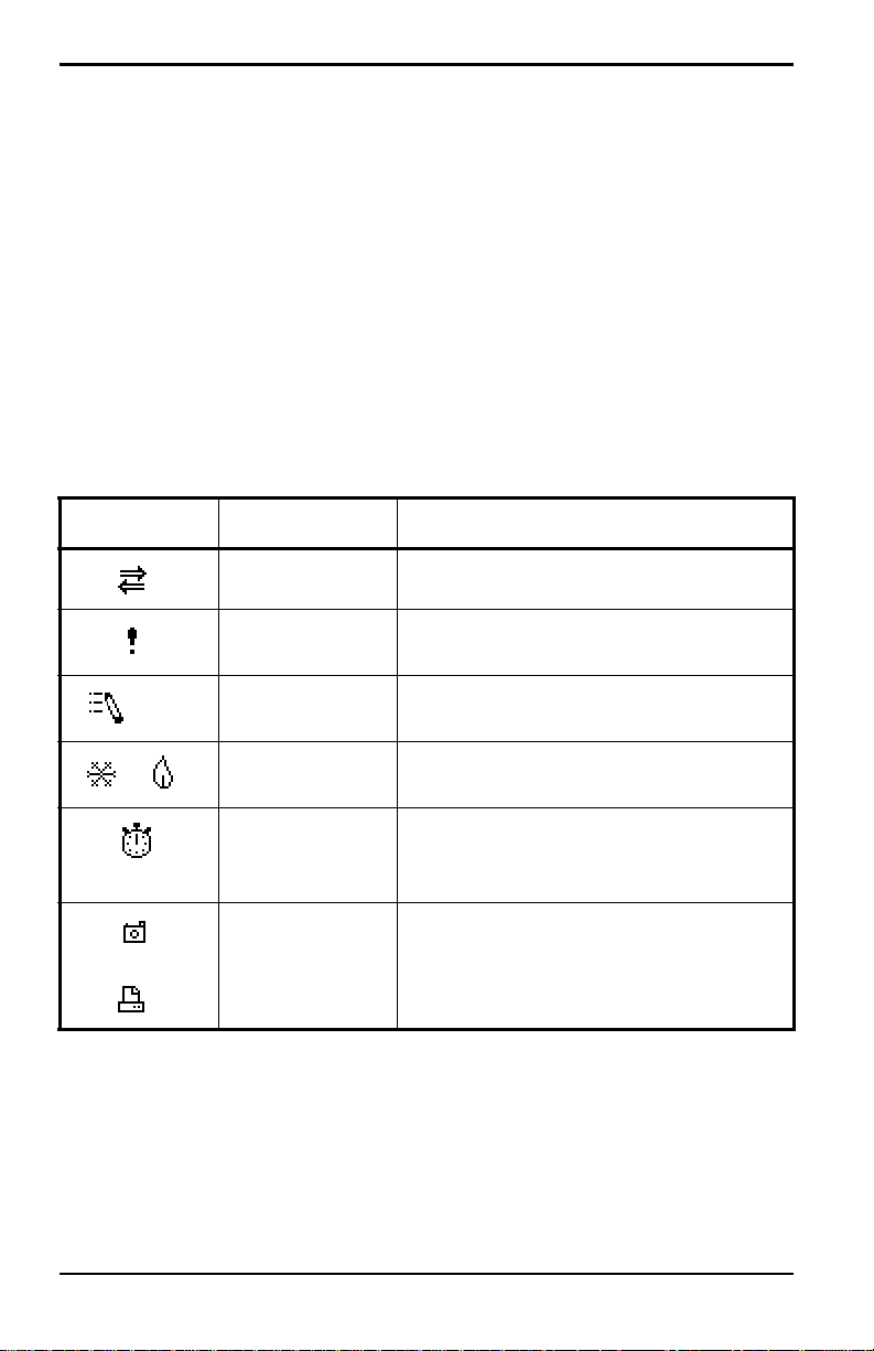
Chapter 2. Initial Setup
2.4.1 Screen (cont).
The middle of the screen shown in Figure 6 on page 15 is the work area,
which displays the measured parameters, numeric measurements, and both
bar and line graphs. (When you enter a selection on the Menu Bar discussed
in Chapter 3, Programming Site Data, this area displays menu prompts.) A
line at the bottom of the area also displays error code messages, which are
described in more detail in Chapter 9, Diagnostics and Troubleshooting.
The system tray displays icons that indicate meter operations not otherwise
shown. Table 3 below lists the icons and their meanings.
Table 3: Icons in the System Tray
Icon Function Meaning
IR Transfer IR data transfer in progress.
Alert Indicates the meter encountered an
error in operation.
Log Indicates a log is pending (no marks)
or running (marks).
Heating/
cooling
Stopwatch Calibration Gate Operation: Watch is
Snapshot
(To file)
(To Printer)
Indicates heating or cooling energy
mode.
stopped when the gate is closed, or
runs when it is open.
Indicates that the Snapshot function
has been activated, so users can take
screen captures (see page 130).
The bottom of the screen displays the three function key options: F1, F2
and F3. These keys have different functions, depending on the task you are
performing.
16 Transport® Model PT878 Portable Liquid Flowmeter User’s Manual

Chapter 2. Initial Setup
2.4.2 Keypad
The PT878 keypad has 25 keys. The functions for each key are as follows
(see Figure 7 on page 18):
• 3 function keys ([F1], [F2], [F3]) — enable you to select the special
functions which appear at the bottom of the screen.
• 12 numeric keys (including – and .) — enable you to enter numeric data.
• 4 arrow keys ([W], [X], [S], [T]) — enable you to move through the
menu options.
• [?] Help key— enables you to access on-line help (discussed on
page 19).
• [MENU] Menu key — enables you to access the Main Menu.
• [ENTER] — enables you to enter a particular menu, and enters selected
values into the PT878 memory.
• [SEL] — enables you to move between data measurements on the screen.
• [ESC] — enables you to exit menus or me nu options at any time; cancels
a numeric entry.
• Red key [ ] — turns the power on or off, and toggles the backlight on
or off.
Transport® Model PT878 Portable Liquid Flowmeter User’s Manual 17
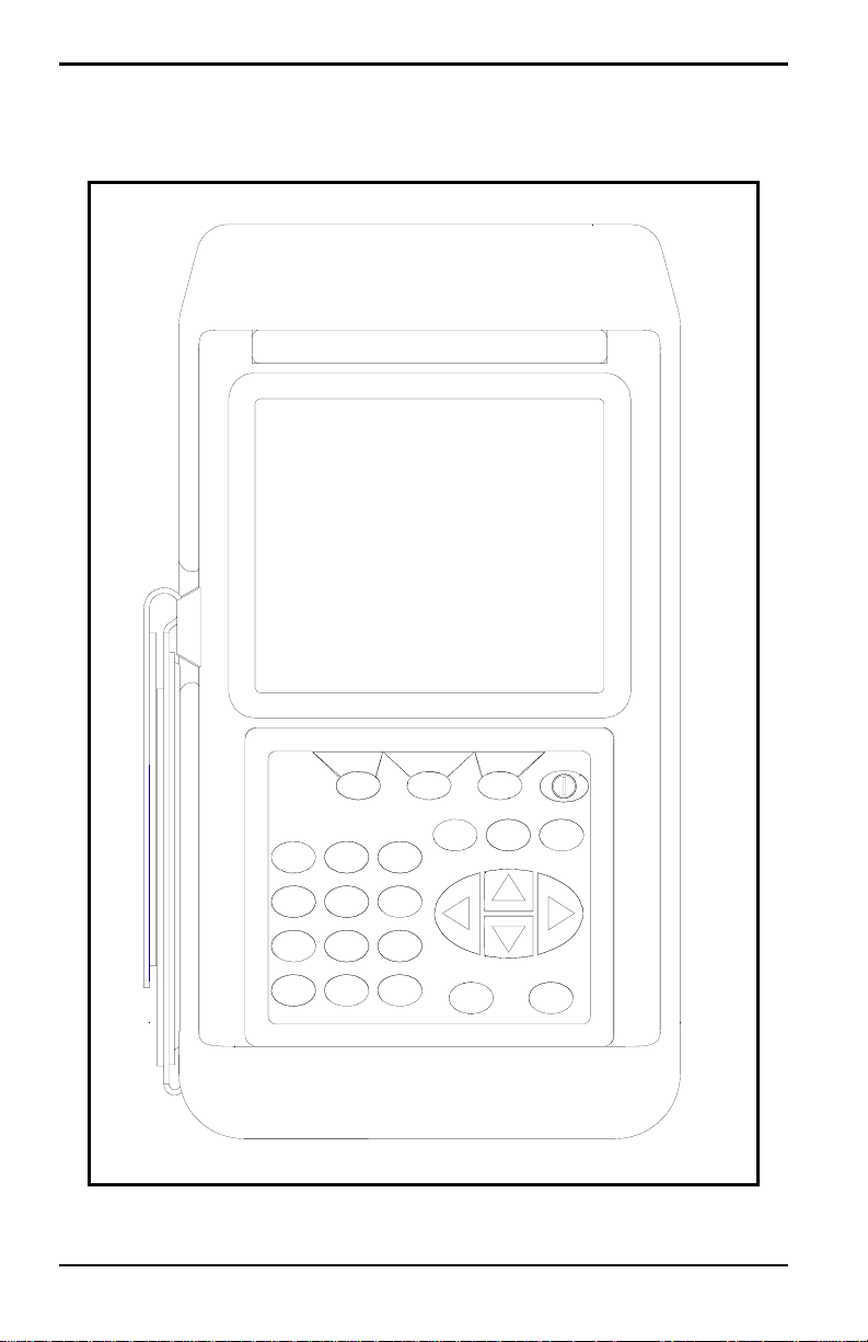
Chapter 2. Initial Setup
2.4.2 Keypad (cont.)
PT878
?
MENU
F3
ESC
SEL
ENTER
F1
2
1
4
5
8
7
0
•
F2
3
6
9
–
Figure 7: PT878 Keypad
18 Transport® Model PT878 Portable Liquid Flowmeter User’s Manual
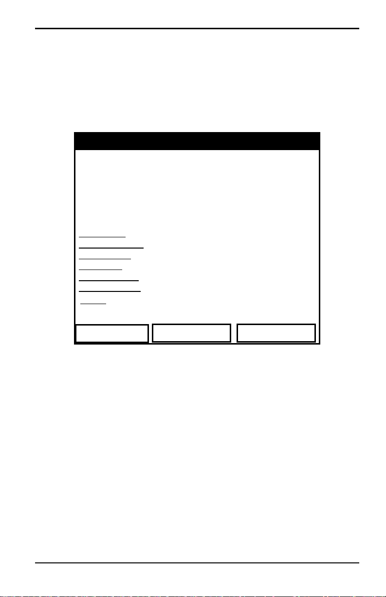
Chapter 2. Initial Setup
2.5 Obtaining On-Line Help
The PT878 offers context-sensitive on-line help screens that describe
various features. You can access on-line help at any time by pressing the [?]
key. The screen appears similar to Figure 8 below.
Help
Velocity, ft/s
Use the arrows and the enter key to
select from the links below. Press [F2]
to return to the TOC.
Site Menu
Program Menu
Meter Menu
Log Menu
Service Menu
Miscellaneous
About
Back TOC
Table of Contents
Signal, dB
Close
Figure 8: Main Help Menu
Use the three function keys and the [
S] and [T] arrow keys to navigate to
the desired menu, and press [ENTER]. Repeat this procedure to access the
desired topic within the menu. When you have finished using the Help
menu:
• Press [F1], Back, to move back one level.
• Press [F2], TOC, to return to the Table of Contents.
• Press [F3], Close, to return to the previous screen.
Transport® Model PT878 Portable Liquid Flowmeter User’s Manual 19

Chapter 2. Initial Setup
[no content intended for this page — proceed to next page]
20 Transport® Model PT878 Portable Liquid Flowmeter User’s Manual

Chapter 3. Programming Site Data
Chapter 3. Programming Site Data
On the PT878, a Program Menu (part of the Main Menu) enables you to
enter information that is specific to each site:
• Transducer types and paths
• Pipe materials and linings
• Fluid types
• Heating or cooling energy flow rate
• Analog input and output parameters
• Digital output parameters
• User functions
• Correction factors
For immediate operation, the PT878 requires only transducer, pipe and fluid
data. However, additional information allows you to tailor measurements as
specifically as possible to your particular application. Once you have
entered this data, you can save it in files and recall these files for later use.
The PT878 can store up to 1 MB (or 32 site files) of data in the meter at any
one time. But through the infrared link, users can store an unlimited number
of sites in a PC, and then upload the sites they will actually use.
This chapter covers entering:
• Transducer, pipe, and fluid parameters
• Input/output and other setup parameters
• User functions.
Transport® Model PT878 Portable Liquid Flowmeter User’s Manual 21
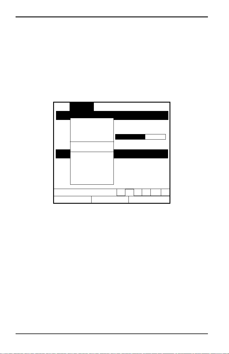
Chapter 3. Programming Site Data
3.1 Entering the Program Menu
To enter the Program Menu, press the [MENU] key at the lower right of the
PT878 keypad. The Menu Bar replaces the Status Bar at the top of the
screen. Press the [
Program Menu. At the Program Menu, press
similar to Figure 9 below. While following the programming instructions,
see Figure 139 on page 222 of Appendix A, Me nu Ma ps .
X] arrow key once to scroll from the Site Menu to the
[ENTER]. The screen appears
Site Program Meter Logging Service
Transducer
Vel
ocity, ft/s
Pipe
Lining
Fluid
0.00
Path
Energy
Delta
-T, ns
Analog Input
Analog Output
Digital Output
User Functions
0.10
Co
Correction Factors
Signal, dB
32
Volume, l/s
0.0
E0: No Errors
Figure 9: Program Menu
To scroll to a particular option, press the [
T]or [S] arrow keys until you
reach the option. Then press [ENTER] to open the option window.
When entering parameters in an option, press:
• The [T] key to step through the available parameters
• The [S] key to scroll back to a previously entered parameter
• The [F2] key (Cancel) or the [ESC] key to exit an option at any time and
return to Operate Mode without changing the parameters.
Note: If you enter an incorrect numeric value, press the [W] key to erase
the last digit entered.
22 Transport® Model PT878 Portable Liquid Flowmeter User’s Manual
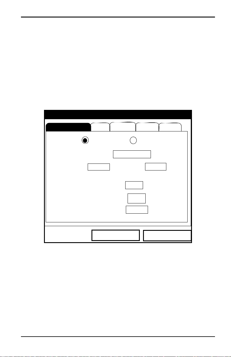
Chapter 3. Programming Site Data
3.2 Entering Transducer Parameters
To enter the Transducer option, scroll to the Transducer entry on the
Program Menu and press
below. To step through each parameter, press the [
Figure 143 on page 227 of Appendix A.
Note: Refer to the Liquid Transducer Installation Guide (916-055) for
additional information about transducers and configurations.
.
[ENTER]. The screen appears similar to Figure 10
T] key. Refer to
Transducer/Pipe
Transducer
Type: Wetted
Frequency
Pipe
Transducer
2.00
Wedge Ang
Wedge Tmp
Wedge SS
Cancel
Lining Path
Fluid
Clamp-on
Special
MHz
Tw
50
25
1219.2
°
°C
14
m/s
µs
OK
Figure 10: Transducer Option Window
1. Th e first prompt asks you to select whether you are using a wetted or a
clamp-on transducer.
a. Use the [W] and [X] keys to scroll between the two types.
b. Press [ENTER] to confirm the choice.
Transport® Model PT878 Portable Liquid Flowmeter User’s Manual 23

Chapter 3. Programming Site Data
3.2 Entering Transducer Parameters (cont.)
Note: The choices made early in the Transducer and Pipe options
determine the prompts available later. If the PT878 does not scroll to
a particular parameter, it is not necessary for that transducer or pipe
type. For example, the Lining window is not available if you select a
wetted transducer.
2. The next prompt asks you to enter the transducer number (printed on
the transducer itself), or to specify that you are using a special
application transducer.
a. From the Type prompt, press the [T] key to reach the Transducer
prompt, and press
b. A drop-down list of transducer numbers opens as in Figure 11 on
page 25. (The list varies, depending on whether you have selected
wetted or clamp-on in the previous prompt. See Table 4 on page 25.)
Press the [
T] or [S] keys to scroll to the appropriate number, or
scroll to “Special” for a special application transducer. To speed
scrolling, you can press the [
W] key to scroll up by a page.
[
[ENTER].
X] key to scroll down by a page, or the
c. Press [ENTER] to confirm your selection.
The program now varies, depending on whether you have selected standard
or special transducers.
• If you have selected a standard wetted or clamp-on transducer, the
PT878 comes programmed with the needed parameters. Proceed to
Confirming Entries on page 30.
• However, if you have selected a special application transducer, go to
page 26.
24 Transport® Model PT878 Portable Liquid Flowmeter User’s Manual
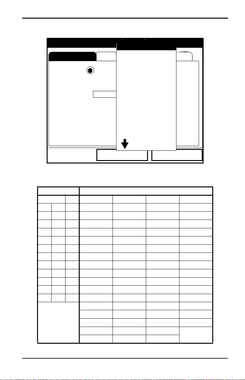
Chapter 3. Programming Site Data
Transducer
Transducer/Pipe
Pipe
SPECIAL
#40
Lining Path
Fluid
#41
Type: Wetted
Transducer
Frequency
2.00
#42
#43
Special
#44
MHz
#45
Clamp-on
Tw
14
µs
#46
Wedge Ang
Wedge Tmp
Wedge SS
#48
#49
Cancel
#47
50
25
1219.2
°C
m/s
OK
°
Figure 11: Transducer Numbers Drop-Down List
Table 4: Transducer Numbers Available
WETTED CLAMP-ON
SPECIAL 64 SPECIAL 23 (Shear) 113 (Shear) 307 (Shear)
40 52 65 1 (Rayleigh) 24 (Shear) 114 (Shear) 308 (Shear)
41 53 66 2 (Rayleigh) 25 (Shear) 115 (Shear) 309 (Shear)
42 54 67 3 (Rayleigh) 26 (Shear) 116 (Shear) 310 (Shear)
43 55 68 10 (Shear) 27 (Shear) 117 (Shear) 311 (Shear)
44 56 69 10 (Shear) 28 (Shear) 125 (Shear) 312 (Shear)
45 57 70 11 (Shear) 29 (Shear) 126 (Shear) 313 (Shear)
46 58 71 12 (Shear) 30 (Shear) 127 (Shear) 314 (Shear)
47 59 72 13 (Shear) 31 (Shear) 133 (Shear) 315 (Shear)
48 60 73 14 (Shear) 32 (Shear) 136 (Shear) 401 (Shear)
49 61 74 15 (Shear) 33 (Shear) 137 (Shear) 402 (Shear)
50 62 75 16 (Shear) 34 (Shear) 139 (Shear) 403 (Shear)
51 63 76 17 (Shear) 35 (Shear) 301 (Shear) 407 (Shear)
18 (Shear) 36 (Shear) 302 (Shear) 408 (Shear)
19 (Shear) 37 (Shear) 303 (Shear) 409 (Shear)
20 (Shear) 38 (Shear) 304 (Shear) 410 (Shear)
21 (Shear) 39 (Shear) 305 (Shear)
22 (Shear) 112 (Shear) 306 (Shear)
Transport® Model PT878 Portable Liquid Flowmeter User’s Manual 25

Chapter 3. Programming Site Data
3.2.1 Parameters for Special Transducers
Note: The factory will supply the information required below with the
transducers.
3. The prompt asks for the transducer frequency, to transmit a signal at a
frequency to which the transducer can respond.
a. From the Transducer prompt, press the [T] key to reach the
Frequency prompt, and press
b. A drop-down list of five frequencies opens, ranging from 0.50 to
4.00 MHz. Scroll to the desired frequency, and press
4. The next prompt asks for Tw, the time delay. This parameter is actually
the time the transducer signal spends travelling through the transducer
and cable. The PT878 calculates the flow rate from the upstream and
downstream transit times in the fluid, so the Tw (time delay) must be
subtracted out for an accurate measurement. The factory supplies the
time delay on a sheet of paper inside the transducer case.
a. From the Frequency prompt, press the [X] key to reach the Tw
prompt, and press
[ENTER].
[ENTER].
[ENTER].
b. Use the numeric keys to enter the GE-supplied time delay and press
[ENTER].
The program now varies, depending on whether you have selected a wetted
or a clamp-on transducer.
• If you have selected a special wetted transducer, proceed to
Confirming Entries on page 30.
• Special clamp-on transducers require three more inputs: wedge
angle, wedge temperature, and wedge soundspeed.
5. When calculating the flow rate, the PT878 must take into account the
wedge angle, the angle of the ultrasonic transmission.
a. From the Tw prompt, press the [T] key to reach the Wedge Angle
prompt, and press
b. Use the numeric keys to enter the factory-supplied wedge angle (in
degrees) and press
26 Transport® Model PT878 Portable Liquid Flowmeter User’s Manual
[ENTER].
[ENTER].
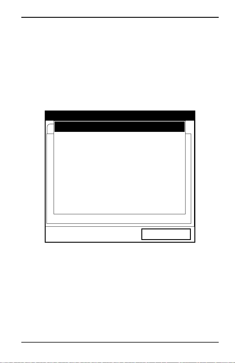
Chapter 3. Programming Site Data
3.2.1 Parameters for Special Transducers (cont.)
Note: If the error message in Figure 12 below, or one similar to Figure 13
on page 28 appears, the Pipe Soundspeed, Wedge Soundspeed,
and/or the Wedge Angle may be in error. Review the pipe and wedge
parameters currently entered and change one or more as necessary.
Note: To change pipe information, see Entering Pipe Parameters on
page 30.
Transducer/Pipe
* * * WARNING * * *
Critical Angle Exceeded!
Check Angles, Soundspeed!!!!!!!!
Cancel
OK
Figure 12: High Angle Error Message Window
Transport® Model PT878 Portable Liquid Flowmeter User’s Manual 27
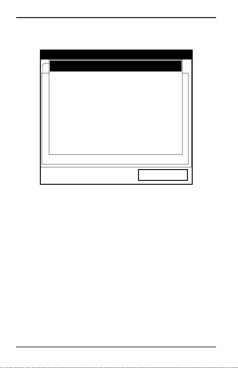
Chapter 3. Programming Site Data
3.2.1 Parameters for Special Transducers (cont.)
Transducer/Pipe
Invalid Value — Too Low
15 is Too Low.
The valid range is from:
25.000 to 90.000 °
Cancel
OK
Figure 13: Low Angle Error Message Window
Note: When the corrected information is entered, a message similar to
Figure 14 appears. Press [F3] (OK).
28 Transport® Model PT878 Portable Liquid Flowmeter User’s Manual

Chapter 3. Programming Site Data
3.2.1 Parameters for Special Transducers (cont.)
Transducer/Pipe
* * * WARNING * * *
Transducer Spacing has changed!
New Spacing:
0.964 inches ( 24.493 mm)
Cancel
OK
Figure 14: Transducer Spacing Change Window
6. The PT878 must also take into account the wedge temperature.
a. From the Wedge Angle prompt, press the [T] key to reach the
Wedge Temperature prompt, and press
b. Use the numeric keys to enter the wedge temperature (in degrees F
or C) and press
7. Finally, the PT878 requires the wedge soundspeed.
a. From the Wedge Temp prompt, press the [T] key to reach the
Wedge SS prompt, and press
b. Use the numeric keys to enter the factory-supplied wedge
[ENTER].
[ENTER].
soundspeed (in ft/sec or m/sec) and press
[ENTER].
[ENTER].
Pressing the [T] key returns the meter to the Transducer tab at the top.
Transport® Model PT878 Portable Liquid Flowmeter User’s Manual 29
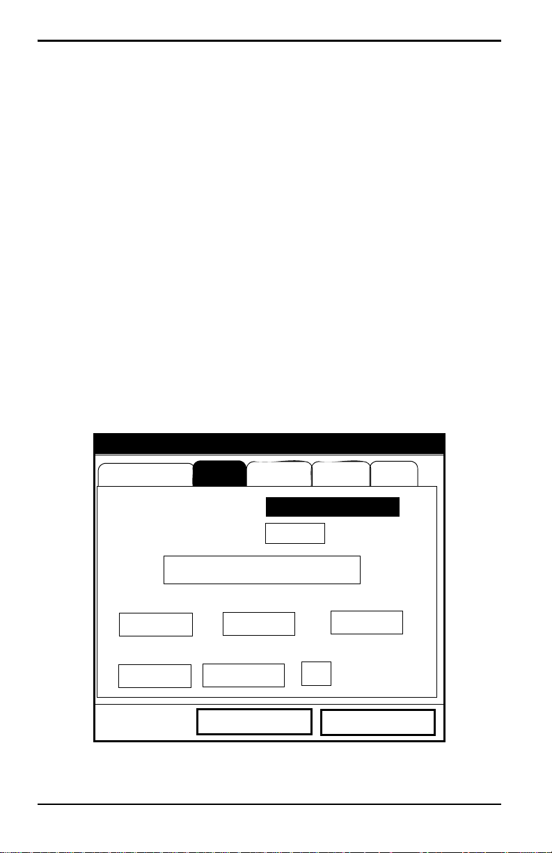
Chapter 3. Programming Site Data
3.2.2 Confirming Entries
• To confirm the entries and return to Operate mode, press [F3] (OK).
• To leave the window without confirming the entries, press [F2] (Cancel)
or the
[ESC] key.
In either case, the PT878 returns to Operate Mode.
3.3 Entering Pipe Parameters
To enter the Pipe option, scroll to the Pipe entry on the Program Menu and
[ENTER]. (From the Transducer window , you can scroll back up to the
press
Transducer tab and press the [
press
[ENTER].) The screen appears similar to Figure 15 below. To step
through each parameter, press the [
of Appendix A, Menu Maps.
Note: Refer to the brochure Soundspeeds and Pi pe Size Data (9 14 -004 ) for
additional information about pipe sizes and soundspeeds.
X] arrow key to reach the Pipe window, and
T] key . Refer to Figure 139 on page 222
Transducer/Pipe
Transducer
Sound Speed
Pipe Fluid
Material
Lining
Other
600.3
Path
m/s
Measure Wall with TGauge
OD, mm
5
Nominal
OD x PI, mm
15.708
Schedule
Wall, mm
2
ANSI
Cancel
OK
Figure 15: Pipe Option Window
30 Transport® Model PT878 Portable Liquid Flowmeter User’s Manual

Chapter 3. Programming Site Data
3.3 Entering Pipe Parameters (cont.)
1. The first prompt asks you to select the pipe material.
a. Press [ENTER] to enter the material prompt.
b. A drop-down list of materials opens. Table 5 below lists the
available preprogrammed materials on the list. Press the [
keys to scroll to the appropriate material, or scroll to “Other” for a
material not on the list. You can press the [
a page, or the [
W] key to scroll up by a page.
Table 5: Preprogrammed Pipe Materials
Pipe Material
Category Specific Material
Al — Aluminum Rolled
Brass None
Cu — Copper Annealed or Rolled
CuNi — Copper/Nickel 70% Cu 30% Ni or 90% Cu 10% Ni
Glass Pyrex, Flint, or Crown
Gold Hard-drawn
Inconel None
Iron Armco, Ductile, Cast, Electrolytic
Monel None
Nickel None
Plastic
Nylon, Polyethylene, Polypropylene, PVC
(CPVC), or Acrylic
Steel Carbon Steel or Stainless Steel
Tin Rolled
Titanium None
Tungsten Annealed, Carbide, Drawn
Zinc Rolled
Other* Any material
X] key to scroll down by
T] or [S]
c. Press [ENTER] to confirm the choice.
Transport® Model PT878 Portable Liquid Flowmeter User’s Manual 31
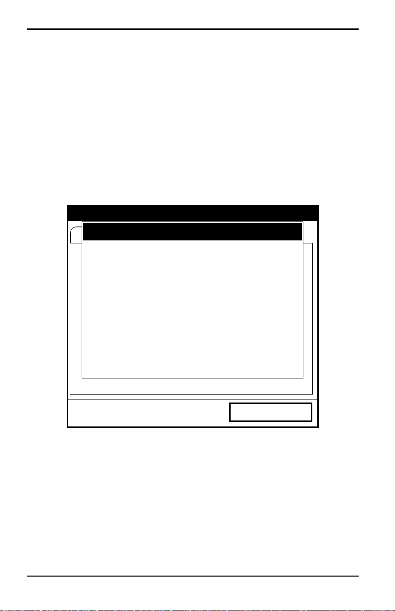
Chapter 3. Programming Site Data
3.3 Entering Pipe Parameters (cont.)
d. If you have selected “Other,” the meter prompts you to enter the
soundspeed. Use the numeric keys to type the desired soundspeed in
the text box, and press
Note: If the “Other” Pipe soundspeed entered is too large, given the
previously entered Wedge soundspeed and angles, an error message
similar to Figure 16 below will appear. Press [F3] (OK) (the error
message disappears), and enter another soundspeed within the range
specified.
100000 is Too High
The valid range is from:
3330.052 to 24000.000 ft/s
[ENTER] to confirm the choice.
Transducer/Pipe
Invalid Value — Too High
Cancel
OK
Figure 16: Soundspeed Error Message Window
Note: When the corrected soundspeed is entered, a message similar to
Figure 17 on page 33 appears. Press [F3] (OK).to return to the Site
Menu.
32 Transport® Model PT878 Portable Liquid Flowmeter User’s Manual
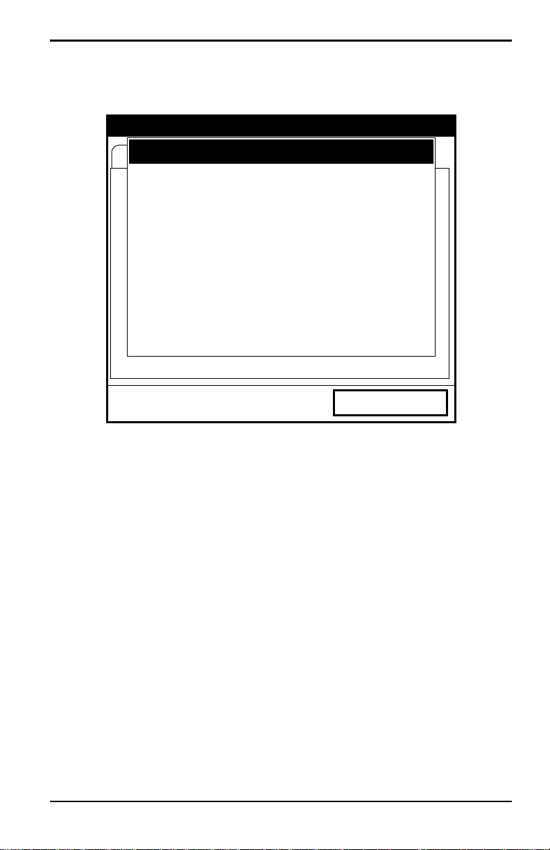
3.3 Entering Pipe Parameters (cont.)
Transducer/Pipe
* * * WARNING * * *
Transducer Spacing has changed!
New Spacing:
0.964 inches ( 24.493 mm)
Chapter 3. Programming Site Data
Cancel
OK
Figure 17: Transducer Spacing Change Window
2. The next prompt asks if you wish to measure the pipe wall with the
internal thickness gauge. If you press
[ENTER], the program moves to
the T-Gauge Display option (as covered on page 159). When you have
completed setting up and using the thickness gauge (as discussed in
Chapter 8), press
3. For pipe diameter, two alternatives are available. At the Diameter
[F2] or [F3] to return to the Pipe tab.
prompt, the meter asks for the pipe outside diameter and thickness. But
if you have selected certain pipe materials (carbon or stainless steel,
cast iron, PVC and CPVC), you have the option of entering the pipe
dimensions by a standardized schedule. Once you enter the nominal
pipe size and identification, the PT878 determines the OD and wall
thickness from an internal table.
Transport® Model PT878 Portable Liquid Flowmeter User’s Manual 33

Chapter 3. Programming Site Data
3.3 Entering Pipe Parameters (cont.)
If you select a material that uses the Diameter alternative:
a. You must select from two choices, outside diameter or
circumference.
• The prompt moves to the OD (outside diameter) text box. Type the
thickness (in mm or in.) into the text box, and press
confirm the choice, or
[ENTER] to
• Move the prompt to the OD X PI (circumference) text box. Type
the OD (in mm or in.) into the box, and press
your choice.
b. In either case, the next prompt asks for the wall thickness. Type the
value (in mm or in.) into the box, and press
choice.
Note: The measurement units shown depend on the choices you have made
in the English/Metric window or the Meter Settings menu.
[ENTER] to confirm
[ENTER] to confirm your
If you select a material that has the Schedule option:
a. The prompt as ks if you wish to apply ANSI (the ANSI schedule).
[ENTER] to select (or deselect) the ANSI box. (If you do not
Press
select the ANSI option, the prompt moves to the OD text box, and
you enter the parameters for the Diameter alternative as discussed
above.)
b. Press the [W] key twice to move the prompt to the Nominal pipe
size drop-down menu. Press
the desired pipe size, and press
c. Press the [X] key to move the prompt to the Schedule drop-down
menu. Press
schedule, and press
[ENTER] to open the menu. Scroll to the desired
[ENTER] to confirm the choice.
After entering either diameter or schedule settings, pressing the [
[ENTER] to open the menu. Scroll to
[ENTER] to confirm your choice.
S] key
returns the meter to the Pipe Material prompt.
34 Transport® Model PT878 Portable Liquid Flowmeter User’s Manual
 Loading…
- Home
- Brands
- Panametrics Manuals
- Panametrics PT878GC
- Panametrics PT878GC Quick Start Manual
Download or browse on-line these Quick Start Manual for Panametrics PT878GC Measuring Instruments.
Panametrics PT878GC Manual Information:
|
This manual for Panametrics PT878GC, given in the PDF format, is available for free online viewing and download without logging on. |
Download Manual |
More Manuals:
In case you failed to obtain relevant information in this document, please, look through related operating manuals and user instructions for Panametrics PT878GC. Summary of Contents:
|


