Cервисные мануалы по ноутбукам Packard Bell
![]()
Здесь представлена подборка мануалов по разборке ноутбуков Packard Bell.
Все инструкции представлены на английском языке. Для поиска модели введите её номер в основном поиске. Все действия описанные в мануалах вы выполняете на свой страх и риск:
Cервисный мануал по ноутбукам Packard Bell easynote a7 versa vx
Cервисный мануал по ноутбукам Packard Bell versa p520
Cервисный мануал по ноутбукам Packard Bell versa m340 e2000
Cервисный мануал по ноутбукам Packard Bell ipower gx
Cервисный мануал по ноутбукам Packard Bell easynote xs
Cервисный мануал по ноутбукам Packard Bell easynote w7 dragon sn
Cервисный мануал по ноутбукам Packard Bell easynote w3 dragon a
Cервисный мануал по ноутбукам Packard Bell easynote v
Cервисный мануал по ноутбукам Packard Bell easynote v mv
Cервисный мануал по ноутбукам Packard Bell easynote t5
Cервисный мануал по ноутбукам Packard Bell easynote sw w
Cервисный мануал по ноутбукам Packard Bell easynote sj
Cервисный мануал по ноутбукам Packard Bell easynote sb
Cервисный мануал по ноутбукам Packard Bell easynote s
Cервисный мануал по ноутбукам Packard Bell easynote r7 versa m540
Cервисный мануал по ноутбукам Packard Bell easynote r
Cервисный мануал по ноутбукам Packard Bell easynote mz
Cервисный мануал по ноутбукам Packard Bell easynote mx
Cервисный мануал по ноутбукам Packard Bell easynote me
Cервисный мануал по ноутбукам Packard Bell easynote mb

- Manuals
- Brands
- Packard Bell Manuals
- Laptop
- dot s Series
- Service manual
-
Contents
-
Table of Contents
-
Troubleshooting
-
Bookmarks
Quick Links
Packard Bell dot s Series
Service Guide
Service guide files and updates are available
on the ACER/CSD web; for more information,
please refer to
http://csd.acer.com.tw
PRINTED IN TAIWAN
Downloaded from LpManual.com Manuals
Related Manuals for Packard Bell dot s series
Summary of Contents for Packard Bell dot s series
-
Page 1
Packard Bell dot s Series Service Guide Service guide files and updates are available on the ACER/CSD web; for more information, please refer to http://csd.acer.com.tw PRINTED IN TAIWAN Downloaded from LpManual.com Manuals… -
Page 2: Revision History
Revision History Please refer to the table below for the updates made to this service guide. Date Chapter Updates Downloaded from LpManual.com Manuals…
-
Page 3
Copyright Copyright © 2009 by Acer Incorporated. All rights reserved. No part of this publication may be reproduced, transmitted, transcribed, stored in a retrieval system, or translated into any language or computer language, in any form or by any means, electronic, mechanical, magnetic, optical, chemical, manual or otherwise, without the prior written permission of Acer Incorporated. -
Page 4
Conventions The following conventions are used in this manual: Denotes actual messages that appear SCREEN MESSAGES on screen. NOTE Gives bits and pieces of additional information related to the current topic. WARNING Alerts you to any damage that might result from doing or not doing specific actions. -
Page 5
Preface Before using this information and the product it supports, please read the following general information. This Service Guide provides you with all technical information relating to the BASIC CONFIGURATION decided for Acer’s «global» product offering. To better fit local market requirements and enhance product competitiveness, your regional office MAY have decided to extend the functionality of a machine (e.g. -
Page 6
Downloaded from LpManual.com Manuals… -
Page 7: Table Of Contents
Table of Contents System Specifications Features …………1 System Block Diagram .
-
Page 8
Table of Contents Removing the I/O Board ……… . .66 Removing the Mainboard . -
Page 9
Table of Contents USB Failure ……….. .138 Wireless Function Failure . -
Page 10
Table of Contents Downloaded from LpManual.com Manuals… -
Page 11: System Specifications
Chapter 1 System Specifications Features Below is a brief summary of the computer’s many features: Operating System ® Genuine Windows 7 Starter for Small Notebook PCs • ® Genuine Windows 7 Home Basic (China only) • Platform ® ™ Intel Atom processor N450 (512 KB L2 cache, 1.66 GHz, DDR2 667 MHz) •…
-
Page 12: Dimensions And Weight
I/O Interface Multi-in-1 card reader • Three USB 2.0 ports • External display (VGA) port • Headphone/speaker/line-out jack • Microphone-in jack • Ethernet (RJ-45) port • DC-in jack for AC adapter • Dimensions and Weight 258.5 (W) x 185 (D) x 25.2 (H) mm (10.17 x 7.28 x 0.99 inches) •…
-
Page 13: Special Keys And Controls
Special keys and controls 84-key keyboard, 93% of standard-size keyboard • Multi-gesture touchpad, supporting two-finger scroll, pinch, rotate, flip • ® 12 function keys, four cursor keys, one Windows key, hotkey controls, embedded numeric • keypad, international language support Power button with LED •…
-
Page 14: System Block Diagram
System Block Diagram Chapter 1 Downloaded from LpManual.com Manuals…
-
Page 15: Front View
Front View Component Icon Description Status Indicators Light-Emitting Diodes (LED) that light up to show the status of the computer’s functions and components. Left View Component Icon Description DC-in jack Connects to an AC adapter. External display Connects to a display device (e.g., external monitor, LCD (VGA) port projector).
-
Page 16: Bottom And Rear View
Component Icon Description Kensington lock Connects to a Kensington-compatible computer security lock. slot Ethernet (RJ-45) Connects to an Ethernet 10/100-based network. port Bottom and Rear View Component Icon Description Battery bay Houses the computer’s battery pack. Note: The battery shown is for reference only. Your PC may have a different battery, depending on the model purchased.
-
Page 17: Keyboard Area And Lcd Panel
Keyboard Area and LCD Panel Component Icon Description Webcam Web camera for video communication Microphone Internal microphone for sound recording. Display screen Also called Liquid-Crystal Display (LCD), displays computer output. Power button/ Indicates when the computer is turned on. indicator Keyboard Provides all the features of a full-sized, computer keyboard.
-
Page 18
Component Icon Description Bluetooth Indicates the status of the Bluetooth communication. communication (only for certain models) indicator 3G/ Indicates the status of 3G/Wireless LAN communication: Wireless LAN Blue light on — 3G on / WiFi on or off • communication Orange light on —… -
Page 19: Touchpad Basics
Touchpad Basics The following items show you how to use the TouchPad: • Move your finger across the TouchPad (1) to move the cursor. • Press the left (2) and right (3) buttons located beneath the TouchPad to perform selection and execution functions.
-
Page 20: Using The Keyboard
Using the Keyboard Your Packard Bell Dot S has a close-to-full-sized keyboard and an embedded numeric keypad, separate cursor, lock, function and special keys. Lock Keys and Embedded Numeric Keypad The keyboard has three lock keys which you can toggle on and off.
-
Page 21: Windows Keys
Windows Keys The keyboard has two keys that perform Windows-specific functions. Description Windows key Pressed alone, this key has the same effect as clicking on the Windows Start button; it launches the Start menu. It can also be used with other keys to provide a variety of functions: <…
-
Page 22: System Keys
System Keys The computer employs hotkeys or key combinations to access most of the computer’s controls like screen brightness, Bluetooth and WiFi. To activate hot keys, press and hold the <Fn> key before pressing the other key in the hotkey combination. Function Key Description <Fn>…
-
Page 23: Hot Keys
Hot Keys The computer employs hotkeys or key combinations to access most of the computer’s controls like screen brightness and volume output. To activate hotkeys, press and hold the <Fn> key before pressing the other key in the hotkey combination. Hotkey Icon Function…
-
Page 24: Special Key
Special Key You can locate the Euro symbol and the US dollar sign at the upper-center and/or bottom-right of your keyboard. The Euro symbol Open a text editor or word processor. Hold <Alt Gr> and then press the <5> key at the upper-center of the keyboard. NOTE: Some fonts and software do not support the Euro symbol.
-
Page 25: Hardware Specifications And Configurations
Hardware Specifications and Configurations Processor Item Specification Intel® Pineview-M (N450, N470) Processor • Micro-FCBGA8 packaging technologies • On die 512-kB, 8-way L2 cache • Core Logic AMD M880G Chipset • Processor Specifications Mfg. cache Item Cores Package Power Acer P/N Speed Tech Size…
-
Page 26
Item Specification Supports 60 Hz External resolution — VGA port up to 1600 x 900: 16.7 • million colors Resolution • LAN Interface Item Specification Atheros AR8132L LAN Chipset for 10/100LAN LAN connector type RJ-45 LAN connector location Right side Features Support for 10/100 Hard Disk Drive Interface… -
Page 27
Battery Specification Item 3 Cell 6 Cell 2.2 6 Cell 2.8 Vendor & model name SIMPLO UM09G75 SIMPLO UM09H75 SIMPLO UM09H70 Battery Type Li-ion Li-ion Li-ion Pack capacity 2200 mAh 4400 mAh 5600 mAh Normal Voltage 11.1V 11.1V 11.1 Charge Voltage 12.6V 12.6V 12.6… -
Page 28
Chapter 1 Downloaded from LpManual.com Manuals… -
Page 29: System Utilities
Chapter 2 System Utilities BIOS Setup Utility The BIOS Setup Utility is a hardware configuration program built into your computer’s BIOS (Basic Input/ Output System). Your computer is already properly configured and optimized, and you do not need to run this utility. However, if you encounter configuration problems, you may need to run Setup.
-
Page 30: Information
Information The Information screen displays a summary of your computer hardware information. I n s y d e H 2 0 S e t u p U t i l i t y R e v . 3 . 5 Information Main Security…
-
Page 31: Main
Main The Main screen allows the user to set the system time and date as well as enable and disable boot option and recovery. I n s y d e H 2 0 S e t u p U t i l i t y R e v .
-
Page 32: Security
Security The Security screen contains parameters that help safeguard and protect your computer from unauthorized use. I n s y d e H 2 0 S e t u p U t i l i t y R e v . 3 . 5 Information Main Security…
-
Page 33: Setting A Password
Setting a Password Follow these steps as you set the user or the supervisor password: Use the ↑ and ↓ keys to highlight the Set Supervisor Password parameter and press the Enter key. The Set Supervisor Password box appears: S e t S u p e r v i s o r P a s s w o r d E n t e r N e w P a s s w o r d C o n f i r m N e w P a s s w o r d Type a password in the “Enter New Password”…
-
Page 34: Changing A Password
Changing a Password Use the ↑ and ↓ keys to highlight the Set Supervisor Password parameter and press the Enter key. The Set Password box appears. S e t S u p e r v i s o r P a s s w o r d E n t e r C u r r e n t P a s s w o r d E n t e r N e w P a s s w o r d C o n f i r m N e w P a s s w o r d…
-
Page 35: Boot
Boot This menu allows the user to decide the order of boot devices to load the operating system. Bootable devices includes the USB diskette drives, the onboard hard disk drive and the DVD drive in the module bay. I n s y d e H 2 0 S e t u p U t i l i t y R e v .
-
Page 36: Exit
Exit The Exit screen allows you to save or discard any changes you made and quit the BIOS Utility. I n s y d e H 2 0 S e t u p U t i l i t y R e v .
-
Page 37: Bios Flash Utility
BIOS Flash Utility The BIOS flash memory update is required for the following conditions: • New versions of system programs • New features or options • Restore a BIOS when it becomes corrupted. Use the Phlash utility to update the system BIOS flash ROM. NOTE: If you do not have a crisis recovery diskette at hand, then you should create a Crisis Recovery Diskette before you use the Phlash utility.
-
Page 38: Dos Flash Utility
DOS Flash Utility Perform the following steps to use the DOS Flash Utility: Press F2 during boot to enter the Setup Menu. Select Boot Menu to modify the boot priority order, for example, if using USB HDD to Update BIOS, move USB HDD to position 1.
-
Page 39
NOTE: If the AC power is not connected, the following message displays. Plug in the AC power to continue. Flash is complete when the message Flash programming complete displays. Chapter 2 Downloaded from LpManual.com Manuals… -
Page 40: Winflash Utility
WinFlash Utility Perform the following steps to use the WinFlash Utility: Double click the WinFlash executable. Click OK to begin the update. A progress screen displays. When the process is complete, close all programs and applications and reboot the system. Chapter 2 Downloaded from LpManual.com Manuals…
-
Page 41: Remove Hdd/Bios Password Utilities
Remove HDD/BIOS Password Utilities This section provides you with details about removing HDD/BIOS password methods: Removing HDD Password: If you key in the wrong HDD password three times, an error is generated. To reset the HDD password, perform the following steps: After the error is displayed, select the Enter Unlock Password option on the screen.
-
Page 42
Removing BIOS Passwords: To clear the User or Supervisor passwords, open the RAM door and use a metal instrument to short the U72 jumper as shown below. Cleaning BIOS Passwords To clean the User or Supervisor passwords, perform the following steps: From a DOS prompt, execute clnpwd.exe Press 1 or 2 to clean the desired password shown on the screen. -
Page 43: Miscellaneous Utilities
Miscellaneous Utilities Using Boot Sequence Selector Boot Sequence Selector allows the boot order to be changes without accessing the BIOS. To use Boot Sequence Selector, perform the following steps: Enter into DOS. Execute BS.exe to display the usage screen. Select the desired boot sequence by entering the corresponding sequence, for example, enter BS2 to change the boot sequence to HDD|CD ROM|LAN|Floppy.
-
Page 44
Example 1: Read DMI Information from Memory Input: dmitools /r Output: Manufacturer (Type1, Offset04h): Acer Product Name (Type1, Offset05h): Aspire one xxxxx Serial Number (Type1, Offset07h): 01234567890123456789 UUID String (Type1, Offset08h): xxxxxxxx-xxxx-xxxx-xxxx-xxxxxxxxxxxx Asset Tag (Type3, Offset04h): Acer Asstag Example 2: Write Product Name to EEPROM Input: dmitools /wp Acer Example 3: Write Serial Number to EEPROM… -
Page 45
Execute MAC.BAT to write MAC information to eeprom. Chapter 2 Downloaded from LpManual.com Manuals… -
Page 46
Chapter 2 Downloaded from LpManual.com Manuals… -
Page 47: Machine Disassembly And Replacement
Chapter 3 Machine Disassembly and Replacement IMPORTANT:The outside housing and color may vary from the mass produced model. This chapter contains step-by-step procedures on how to disassemble the notebook computer for maintenance and troubleshooting. Disassembly Requirements To disassemble the computer, you need the following tools: Wrist grounding strap and conductive mat for preventing electrostatic discharge •…
-
Page 48: General Information
General Information Pre-disassembly Instructions Before proceeding with the disassembly procedure, make sure that you do the following: 1. Turn off the power to the system and all peripherals. 2. Unplug the AC adapter and all power and signal cables from the system. 3.
-
Page 49: External Module Disassembly Process
External Module Disassembly Process IMPORTANT:The outside housing and color may vary from the mass produced model. External Modules Disassembly Flowchart The flowchart below gives you a graphic representation on the entire disassembly sequence and instructs you on the components that need to be removed during servicing. For example, if you want to remove the main board, you must first remove the keyboard, then disassemble the inside assembly frame in that order.
-
Page 50: Removing The Battery Pack
Removing the Battery Pack 1. Turn computer over. Slide the battery lock in the direction shown. 2. Slide and hold the battery release latch to the release position (1), then lift out the battery pack from the main unit (2). Chapter 3 Downloaded from LpManual.com Manuals…
-
Page 51: Removing The Sd Dummy Card
Removing the SD Dummy Card 1. Push the SD dummy card inwards to eject it. 2. Pull the card out from the slot. Chapter 3 Downloaded from LpManual.com Manuals…
-
Page 52: Removing The Dimm Module
Removing the DIMM Module 1. Remove the one (1) captive screws of the RAM cover. 2. Lift off the RAM cover. 3. Push out the release latches on both sides of the DIMM socket to release the DIMM module. Chapter 3 Downloaded from LpManual.com Manuals…
-
Page 53
4. Remove the DIMM module. Chapter 3 Downloaded from LpManual.com Manuals… -
Page 54: Removing The Hdd Module
Removing the HDD Module 1. See “Removing the Battery Pack” on page 40. 2. Loosen the three (3) captive screws on the HDD cover. 3. Pry up the HDD cover at the location shown and remove. 4. Lift out the pull-tab. Chapter 3 Downloaded from LpManual.com Manuals…
-
Page 55
5. Grasp the pull-tab and pull the HDD module out of the bay. 6. Remove the HDD module. 7. Remove the four (4) screws (two each side) securing the hard disk to the carrier. Step Size Quantity Screw Type HDD Carrier M3*3 Chapter 3 Downloaded from LpManual.com Manuals… -
Page 56
8. Remove the HDD from the carrier. Chapter 3 Downloaded from LpManual.com Manuals… -
Page 57: Removing The Wlan Module
Removing the WLAN Module 1. See “Removing the Battery Pack” on page 40. 2. Loosen the three (3) captive screws on the HDD cover. 3. Pry up the HDD cover at the location shown and remove. 4. Disconnect the antenna cables from the WLAN Module. NOTE: Cable placement is Black to the MAIN terminal (top) and White to the AUX terminal (bottom).
-
Page 58
5. Move the antennas away and remove the one (1) screw. Step Size Quantity Screw Type WLAN Module M2*3 6. Remove the WLAN Module from the WLAN socket. NOTE: When reattaching the antennas, ensure the cables are tucked into the chassis to prevent damage. Chapter 3 Downloaded from LpManual.com Manuals… -
Page 59: Removing The 3G Module
Removing the 3G Module 1. See “Removing the Battery Pack” on page 40. 2. Loosen the three (3) captive screws on the HDD cover. 3. Pry up the HDD cover and remove. 4. Disconnect the antenna cables from the3G module. NOTE: Cable placement is BLUE to the MAIN terminal (bottom) and White to the AUX terminal (top).
-
Page 60
5. Move the antennas away and remove the one (1) screw. Step Size Quantity Screw Type 3G Module M2*3 6. Remove the 3G Module from the 3G socket. When reattaching the antennas, ensure the cables are tucked into the chassis to prevent damage. Chapter 3 Downloaded from LpManual.com Manuals… -
Page 61: Main Unit Disassembly Process
Main Unit Disassembly Process Main Unit Disassembly Flowchart Remove External Modules before proceeding Remove Keyboard Remove Remove Upper Cover Button Board Remove Remove Remove Remove Remove Power Board LED Board Bluetooth Module Bridge Board Function Board Remove Remove Remove Thermal Module Mainboard I/OBoard Remove…
-
Page 62: Removing The Keyboard
Removing the Keyboard 1. Push down on the latch holding the top center of the keyboard. 2. Pry up the keyboard at the top center. 3. Lift up the left and right corners of the keyboard forcefully to release latches under the board. Chapter 3 Downloaded from LpManual.com Manuals…
-
Page 63
4. Turn the keyboard over. 5. Unlock the FPC. 6. Remove the FPC and the keyboard. Chapter 3 Downloaded from LpManual.com Manuals… -
Page 64: Removing The Upper Cover
Removing the Upper Cover 1. See “Removing the Keyboard” on page 52. 2. Unlock and remove the power FFC. 3. Unlock and remove the buttonboard FFC. 4. Remove the seven (7) screws in the upper cover. Step Size Quantity Screw Type Upper Cover M2*8 Chapter 3…
-
Page 65
5. Turn the computer over. Detach the antenna cables from the retention guides. 6. Remove the eleven (11) screws in the lower cover. Step Size Quantity Screw Type Lower Cover M2*8 (red call out) M2x3 (green call out) M2x4 (purple call out) Chapter 3 Downloaded from LpManual.com Manuals… -
Page 66
7. Open the LCD module, stand the LCD module vertically, then pry the upper cover away from the lower cover at the location shown. 8. Continue to pry the covers apart long the front edge. 9. Pry apart the upper cover along the sides. Chapter 3 Downloaded from LpManual.com Manuals… -
Page 67
10. Firmly pull the upper cover up off the latches underneath the cover. 11. Remove the upper cover. Chapter 3 Downloaded from LpManual.com Manuals… -
Page 68: Removing The Button Board
Removing the Button Board 1. See “Removing the Upper Cover” on page 54. 2. Remove the tape from the touchpad FFC. 3. Release the touchpad FFC locking latch and disconnect the touchPad FFC from the cover. 4. Pull the button board FFC off the adhesive. Chapter 3 Downloaded from LpManual.com Manuals…
-
Page 69
5. Remove the two (2) screws securing the TouchPad Bracket to the Upper Cover. Step Size Quantity Screw Type Button Board M2*3 6. Remove the button board from the Upper Cover. Chapter 3 Downloaded from LpManual.com Manuals… -
Page 70: Removing The Power Board
Removing the Power Board 1. See “Removing the Upper Cover” on page 54. 2. Pry the power board off the adhesive and remove. Chapter 3 Downloaded from LpManual.com Manuals…
-
Page 71: Removing The Led Board
Removing the LED Board 1. See “Removing the Upper Cover” on page 54. 2. Unlock and remove the LED FFC from the mainboard. 3. Remove the one (1) screw. Step Size Quantity Screw Type LED Board M2*3 4. Lift the LED Board away from the chassis. Chapter 3 Downloaded from LpManual.com Manuals…
-
Page 72: Removing The Function Board
Removing the Function Board 1. See “Removing the Upper Cover” on page 54. 2. Remove the tape over the cables. 3. Disconnect the microphone cable. 4. Unlock and disconnect the function board FFC. Chapter 3 Downloaded from LpManual.com Manuals…
-
Page 73
5. Pry up the function board and remove. Chapter 3 Downloaded from LpManual.com Manuals… -
Page 74: Removing The Bluetooth Module
Removing the Bluetooth Module 1. See “Removing the Upper Cover” on page 54. 2. Disconnect the Bluetooth cable from the mainboard connector. 3. Pry the Bluetooth module off the adhesive. 4. Disconnect the cable from the Bluetooth module. Chapter 3 Downloaded from LpManual.com Manuals…
-
Page 75: Removing The Bridge Board
Removing the Bridge Board 1. See “Removing the Upper Cover” on page 54. 2. Remove the tape over the cables. 3. Remove the two (2) screws. Step Size Quantity Screw Type Bridge Board M2*3 4. Remove the bridge board from the chassis. Chapter 3 Downloaded from LpManual.com Manuals…
-
Page 76: Removing The I/O Board
Removing the I/O Board 1. See “Removing the Upper Cover” on page 54. 2. See “Removing the Function Board” on page 62. 3. See “Removing the Bridge Board” on page 65. 4. Disconnect the speaker cable. 5. Remove the one (1) screw. Step Size Quantity…
-
Page 77
6. Remove the I/O board from the chassis. Chapter 3 Downloaded from LpManual.com Manuals… -
Page 78: Removing The Mainboard
Removing the Mainboard 1. See “Removing the Power Board” on page 60. 2. See “Removing the LED Board” on page 61. 3. See “Removing the Function Board” on page 62. 4. See “Removing the Bluetooth Module” on page 64. 5. See “Removing the Bridge Board” on page 65. 6.
-
Page 79: Removing The Thermal Module
9. Remove the one (1) screw. Step Size Quantity Screw Type Mainboard M2*3 Removing the Thermal Module 1. See “Removing the Mainboard” on page 68. 2. Disconnect the fan cable. Chapter 3 Downloaded from LpManual.com Manuals…
-
Page 80
3. Remove the three (3) screws. Step Size Quantity Screw Type Thermal Module M2*3 4. Remove the thermal module from the mainboard. Chapter 3 Downloaded from LpManual.com Manuals… -
Page 81: Removing The Lcd Module
Removing the LCD Module 1. See “Removing the Mainboard” on page 68. 2. Remove the DC jack housing. 3. Lift up the chassis and pull the left antenna cables through to the front. 4. Remove the adhesive tape from the antenna cables. Chapter 3 Downloaded from LpManual.com Manuals…
-
Page 82
5. Remove the left antenna cables from the retention guides. 6. Remove the right antenna cables from the antenna guides. 7. Remove the two (2) screws. Step Size Quantity Screw Type LCD Module M2*4 Chapter 3 Downloaded from LpManual.com Manuals… -
Page 83: Removing The Speaker Module
8. Remove the LCD module from the chassis. Removing the Speaker Module 1. See “Removing the I/O Board” on page 66. 2. See “Removing the Mainboard” on page 68. 3. Remove the four (4) screws. Step Size Quantity Screw Type Speakers M2*3 Chapter 3…
-
Page 84
4. Remove the adhesive tape off the speaker cables. 5. Remove the cables from the retention guides and pull away. Chapter 3 Downloaded from LpManual.com Manuals… -
Page 85: Lcd Module Disassembly Process
LCD Module Disassembly Process LCD Module Disassembly Flowchart Remove LCD Panel from Main Unit before proceeding Remove LCD Bezel Remove Camera Module Remove LCD Panel Remove Remove Remove Remove LCD Cable LCD Brackets 3G Antennas Microphone Remove WLAN Antennas Screw List Step Screw Quantity…
-
Page 86: Removing The Lcd Bezel
Removing the LCD Bezel 1. See “Removing the LCD Module” on page 71. 2. Remove the two (2) screw caps. 3. Remove the two (2) screws. Step Size Quantity Screw Type LCD Bezel M2*4 Ni 4. Starting from the bottom center of the bezel, pry the bezel upwards and away from the panel. Move along the edge and down each side until all sides of the bezel are removed.
-
Page 87
Chapter 3 Downloaded from LpManual.com Manuals… -
Page 88: Removing The Camera Module
Removing the Camera Module 1. See “Removing the LCD Bezel” on page 76. 2. Disconnect the camera cable. 3. Pry the camera from the module. Chapter 3 Downloaded from LpManual.com Manuals…
-
Page 89: Removing The Lcd Panel
Removing the LCD Panel 1. See “Removing the Camera Module” on page 78. 2. Lift the foil off the LCD cable. 3. Remove the four (4) securing screws from the LCD Panel. Step Size Quantity Screw Type LCD Panel M2*3 4.
-
Page 90: Removing The Lcd Brackets And Cable
Removing the LCD Brackets and Cable 1. See “Removing the LCD Panel” on page 79. 2. Remove the four (4) screws of the LCD brackets. Step Size Quantity Screw Type LED Panel M2*3 Brackets 3. Turn the LCD panel over to expose the rear. Lift the cable as shown to disengage the adhesive strip securing it in place.
-
Page 91
5. Disconnect the cable from the panel connector and lift the FPC cable from the panel. Chapter 3 Downloaded from LpManual.com Manuals… -
Page 92: Removing The Microphone Module
Removing the Microphone Module 1. See “Removing the LCD Panel” on page 79. 2. Lift the foil tabs off the microphone cable. 3. Lift the foil tab off the micrphone module. 4. Lift the microphone module clear of the module. Chapter 3 Downloaded from LpManual.com Manuals…
-
Page 93: Removing The 3G Antennas
Removing the 3G Antennas 1. See “Removing the LCD Panel” on page 79. 2. Lift the foil tabs off the 3G right cable. 3. Lift the right 3G antenna cable out of the retention guides. Chapter 3 Downloaded from LpManual.com Manuals…
-
Page 94
4. Pry the right 3G antenna off the LCD module cover. 5. Lift the right antenna foil off the adhesive backing. 6. Lift the foil tab off the left 3G antenna cable. Chapter 3 Downloaded from LpManual.com Manuals… -
Page 95: Removing The Wlan Antennas
7. Pull the left 3G antenna cable out of the retention guides. 8. Pry the left 3G antenna off the LCD module cover. Removing the WLAN Antennas 1. See “Removing the 3G Antennas” on page 83. 2. Remove the right WLAN antenna cable from the cable retention guides. Chapter 3 Downloaded from LpManual.com Manuals…
-
Page 96
3. Pry the right WLAN antenna off the LCD module cover. 4. Remove the left WLAN antenna cable away from the retention guides. 5. Pry the WLAN antenna off the LCD module cover. Chapter 3 Downloaded from LpManual.com Manuals… -
Page 97: Lcd Module Reassembly Procedure
LCD Module Reassembly Procedure Replacing the WLAN Antennas 1. Replace the left (white cable) and right (black cable) antennas as shown. Press down on the adhesive pads to secure the antennas in place. 2. Lay the cables along the cable channel. Chapter 3 Downloaded from LpManual.com Manuals…
-
Page 98: Replacing The 3G Antennas
Replacing the 3G Antennas 1. Adhere the left 3G antenna (blue cable) onto the LCD module cover. 2. Lay the cable through the cable channel guides. 3. Replace the foil tabs over the cables. Chapter 3 Downloaded from LpManual.com Manuals…
-
Page 99
4. Adhere the right side 3G antenna (yellow cable) to the LCD module case. 5. Lay the cable through the cable channel guides. 6. Replace the foil tabs over the cables. Chapter 3 Downloaded from LpManual.com Manuals… -
Page 100: Replacing The Microphone
Replacing the Microphone 1. Adhere the microphone into the LCD module cover. 2. Replace the foil tab over the microphone. 3. Lay the microphone cable onto the LCD module cover. Chapter 3 Downloaded from LpManual.com Manuals…
-
Page 101
4. Replace the foil tabs. Chapter 3 Downloaded from LpManual.com Manuals… -
Page 102: Replacing The Lcd Cable
Replacing the LCD Cable 1. Replace the LCD cable connector. 2. Adhere the transparent connector protector. 3. Adhere the LCD cable to LCD panel bottom side edge as shown. NOTE: The circular portion of the cable runs along the panel side. The flat portion of the cable is adhered to the panel base.
-
Page 103: Replacing The Lcd Panel
4. Adhere the webcam LCD cable arm to the LCD panel. NOTE: Pay attention to the proper location of the webcam cable arm. Replacing the LCD Panel 1. Align the left and right LCD panel brackets with the panel. 2. Replace the four (4) screws. Chapter 3 Downloaded from LpManual.com Manuals…
-
Page 104
Step Size Quantity Screw Type LCD Module M2*3 Brackets 3. Replace the LCD panel into the LCD module cover bottom edge first. 4. Replace the four (4) screws. Chapter 3 Downloaded from LpManual.com Manuals… -
Page 105: Replacing The Camera Module
Step Size Quantity Screw Type LCD Module M2*3 Brackets 5. Adhere the LCD cable along the panel edge. 6. Lay the cables though the left and right hinges as shown. Replacing the Camera Module 1. Adhere the camera to the LCD module cover. Chapter 3 Downloaded from LpManual.com Manuals…
-
Page 106
2. Connect the webcam cable. Chapter 3 Downloaded from LpManual.com Manuals… -
Page 107: Replacing The Lcd Bezel
Replacing the LCD Bezel 1. Locate the bezel hinges first and press down until there are no gaps between the bezel and the LCD module cover hinge wells. IMPORTANT: Ensure that the LCD cables pass through the hinge wells and are not trapped by the bezel. 2.
-
Page 108
3. Replace the two (2) screws. Step Size Quantity Screw Type LCD Bezel M2*4 Ni 4. Replace the two (2) screw covers. Chapter 3 Downloaded from LpManual.com Manuals… -
Page 109: Main Module Reassembly Procedure
Main Module Reassembly Procedure Replacing the Speakers 1. Replace the two speaker housings into the bottom cover. 2. Lay the speaker cables into the retention guides. 3. Replace the adhesive tape. Chapter 3 Downloaded from LpManual.com Manuals…
-
Page 110: Replacing The Lcd Module
4. Replace the four (4) screws. Step Size Quantity Screw Type Speakers M2*3 Replacing the LCD Module 1. Place the LCD module onto the main unit lower cover. Chapter 3 Downloaded from LpManual.com Manuals…
-
Page 111
2. Replace the two (2) screws. Step Size Quantity Screw Type LCD Hinges M2*4 3. Lay the right side cables into the retention guides. 4. Lay the left side cables into the retention guides. Chapter 3 Downloaded from LpManual.com Manuals… -
Page 112: Replacing The Thermal Module
5. Replace the adhesive tape. 6. Push the left side cables through the slot in the lower cover. 7. Replace the DC power jack. Replacing the Thermal Module IMPORTANT:Apply a suitable thermal grease and ensure all heat pads are in place before replacing the Thermal Module.
-
Page 113
ShinEtsu 7762 • The following thermal pads are approved for use: 1. Eapus XR-PERemove all traces of thermal grease from the CPU using a lint-free cloth or cotton swab and Isopropyl Alcohol, Acetone, or other approved cleaning agent. 2. Apply a small amount of thermal grease to the centre of the CPU—there is no need to spread the grease manually, the force used during the installation of the Thermal Module is sufficient. -
Page 114
Chapter 3 Downloaded from LpManual.com Manuals… -
Page 115: Replacing The Mainboard
Replacing the Mainboard 1. Ensure that the Mainboard is face up (the CPU is not visible). Place the Mainboard in the chassis, left side first (1), then rotate it downward into position (2). 2. Replace the one (1) screw in the mainboard. Step Size Quantity…
-
Page 116
4. Connect the LCD cable. 5. Replace the adhesive tape over the LCD cable. Chapter 3 Downloaded from LpManual.com Manuals… -
Page 117: Replacing The I/O Board
Replacing the I/O Board 1. Replace the I/O board, inserting the external connectors first 1, then lowering the board into place 2. 2. Replace the one (1) screw. Step Size Quantity Screw Type I/O Board M2*3 3. Connect the speaker cable. Chapter 3 Downloaded from LpManual.com Manuals…
-
Page 118: Replacing The Bridge Board
Replacing the Bridge Board 1. Replace the bridge board, firmly seating the pcb in the underside connectors. 2. Replace the two (2) screws. Step Size Quantity Screw Type Bridge Board M2*3 3. Replace the adhesive tape over the speaker cable. Chapter 3 Downloaded from LpManual.com Manuals…
-
Page 119: Replacing The Bluetooth Module
Replacing the Bluetooth Module 1. Connect the Bluetooth cable to the Bluetooth module 2. Replace the Bluetooth module. 3. Connect the Bluetooth cable to the mainboard. Chapter 3 Downloaded from LpManual.com Manuals…
-
Page 120: Replacing The Function Board
Replacing the Function Board 1. Replace the function board. 2. Connect the function board FFC to the I/O board. 3. Lock the function board FFC. Chapter 3 Downloaded from LpManual.com Manuals…
-
Page 121: Replacing The Led Board
4. Connect the microphone cable to the I/O board. 5. Replace the adhesive tape over the cables as shown. Replacing the LED Board 1. Replace the LED board. Chapter 3 Downloaded from LpManual.com Manuals…
-
Page 122
2. Replace the one (1) screw. Step Size Quantity Screw Type LED Board M2*3 3. Connect the LED board FFC. 4. Lock the LED board FFC. Chapter 3 Downloaded from LpManual.com Manuals… -
Page 123: Replacing The Power Board
Replacing the Power Board 1. Replace the power board. 2. Press down firmly to adhere in location. Chapter 3 Downloaded from LpManual.com Manuals…
-
Page 124: Replacing The Button Board
Replacing the Button Board 1. Replace the button board. 2. Replace the two (2) screws. 3. Adhere the button board FFC to the upper cover. Chapter 3 Downloaded from LpManual.com Manuals…
-
Page 125
4. Connect the touchpad FFC. 5. Lock the touchpad FFC. 6. Replace the adhesive tape. Chapter 3 Downloaded from LpManual.com Manuals… -
Page 126: Replacing The Upper Cover
Replacing the Upper Cover 1. Pull the power board FFC through the upper cover. 2. Replace the upper cover ensuring the hinge covers are seated properly. 3. Press down on the top left and right upper cover edges. Chapter 3 Downloaded from LpManual.com Manuals…
-
Page 127
4. Press down around the upper cover edges. 5. Press down firmly on the upper cover on the locations shown to ensure the underside latches engage properly. Chapter 3 Downloaded from LpManual.com Manuals… -
Page 128
6. Squeeze the bottom edge closed as shown. 7. Turn the computer over and press down on the upper cover top edge. 8. Replace the eleven (11) screws in the lower cover. Step Size Quantity Screw Type Lower Cover M2*8 (red call out) M2x3 (green call out) M2x4 (purple call out) Chapter 3… -
Page 129
9. Pull the cable through completely. 10. Lay the cable through the retention guides. 11. Replace the seven (7) screws in the upper cover. Step Size Quantity Screw Type Upper Cover M2*8 Chapter 3 Downloaded from LpManual.com Manuals… -
Page 130
12. Connect the button board FCC i) and lock it ii). 13. Connect the power FFC i) and lock it ii). Chapter 3 Downloaded from LpManual.com Manuals… -
Page 131: Replacing The Keyboard
Replacing the Keyboard 1. Connect the keyboard FPC i) and lock it ii). 2. Turn the keyboard over. 3. Press down on the keyboard to engage the top center latch. Chapter 3 Downloaded from LpManual.com Manuals…
-
Page 132: Replacing The 3G Module
Replacing the 3G Module 1. Replace the 3G module. 2. Replace the on (1) screw. Step Size Quantity Screw Type 3G Module M2*3 3. Replace the two (2) connectors. Yellow cable on the HDD bay side connector, Blue on the right side connector. Chapter 3 Downloaded from LpManual.com Manuals…
-
Page 133: Replacing The Wlan Module
Replacing the WLAN Module 1. Replace the WLAN module. 2. Replace the one (1) screw. Step Size Quantity Screw Type WLAN Module M2*3 3. Replace the two connectors. The Black cable on the HDD bay side connector, the White cable on the right side edge connector.
-
Page 134: Replacing The Hard Disk Drive
Replacing the Hard Disk Drive 1. Replace the HDD into the carrier. 2. Replace the four (4) screws, two (2) on each side. Step Size Quantity Screw Type HDD Module M3*3 3. Replace the HDD module into the HDD bay. Chapter 3 Downloaded from LpManual.com Manuals…
-
Page 135
4. Slide the HDD module forward to engage the connectors. 5. Ensure the pull tab is tucked down neatly. Chapter 3 Downloaded from LpManual.com Manuals… -
Page 136: Replacing The Dimm Module
Replacing the DIMM Module 1. Replace the DIMM module. 2. Press the DIMM module to lock into place. Replacing the Lower Covers 1. Replace the HDD cover by first locating the external edge flanges (1) and then lowering into place (2). Chapter 3 Downloaded from LpManual.com Manuals…
-
Page 137: Replacing The Battery
2. Replace the DIMM module cover by first inserting the internal edge (1) and then lowering into place (2) as shown. 3. Tighten the three (3) captive screws of the HDD cover and the one (1) captive screw of the DIMM cover. Replacing the Battery 1.
-
Page 138: Replacing The Sd Dummy Card
Replacing the SD Dummy Card 1. Insert the SD Dummy Card into the slot and push until the card clicks into place and is flush with the casing. Chapter 3 Downloaded from LpManual.com Manuals…
-
Page 139: Troubleshooting
Chapter 4 Troubleshooting Common Problems Use the following procedure as a guide for computer problems. NOTE: The diagnostic tests are intended to test only Acer products. Non-Acer products, prototype cards, or modified options can give false errors and invalid system responses. Obtain the failing symptoms in as much detail as possible.
-
Page 140: Power On Issue
Power On Issue If the system doesn’t power on, perform the following actions one at a time to correct the problem. Do not replace a non-defective FRUs: Start Swap AC/Battery Check AC/Batt only power on Check Swap Power Power/B SW/B Whether OK Swap M/B Computer Shutsdown Intermittently…
-
Page 141: No Display Issue
No Display Issue If the Display doesn’t work, perform the following actions one at a time to correct the problem. Do not replace a non-defective FRUs: START Replace LCD LCD panel/cable ok? go to no power panel/cable Power On? trouble shooting step Replace Ext.
-
Page 142: Random Loss Of Bios Settings
Abnormal Video Display If video displays abnormally, perform the following actions one at a time to correct the problem. Reboot the computer. If permanent vertical/horizontal lines or dark spots display in the same location, the LCD is faulty and should be replaced. See “Disassembly Process” on page 38. If extensive pixel damage is present (different colored spots in the same locations on the screen), the LCD is faulty and should be replaced.
-
Page 143: Lcd Failure
LCD Failure If the LCD fails, perform the following actions one at a time to correct the problem. Do not replace a non- defective FRUs: Start Swap LCD cable Check LCD /LCD panel module? Swap M/B Built-In Keyboard Failure If the built-in Keyboard fails, perform the following actions one at a time to correct the problem. Do not replace a non-defective FRUs: START Keyboard FPC…
-
Page 144: Touchpad Failure
TouchPad Failure If the TouchPad doesn’t work, perform the following actions one at a time to correct the problem. Do not replace a non-defective FRUs: Start Re-assemble the T/P FFC to Check M/B T/P FFC Swap/Re- Check Logic assemble the Upper T/P board or T/P FFC…
-
Page 145
Reboot the computer. Navigate to Start Control Panel System and Maintenance System Device Manager. Check the Device Manager to determine that: The device is properly installed. • There are no red Xs or yellow exclamation marks. • There are no device conflicts. •… -
Page 146: Internal Microphone Failure
Internal Microphone Failure If the internal Microphone fails, perform the following actions one at a time to correct the problem. Do not replace a non-defective FRUs: Start Re-assemble the MIC cable Check M/B to M/B Mic cable Swap MIC wire Check MIC of LCD module wire of LCD…
-
Page 147: Hdd Not Operating Correctly
HDD Not Operating Correctly If the HDD does not operate correctly, perform the following actions one at a time to correct the problem. Disconnect all external devices. Run a complete virus scan using up-to-date software to ensure the computer is virus free. Run the Windows 7 Startup Repair Utility: insert the Windows 7 Operating System DVD in the ODD and restart the computer.
-
Page 148: Usb Failure
USB Failure If the USB fails, perform the following actions one at a time to correct the problem. Do not replace a non- defective FRU: Start Re-assemble the IO/B Check IO/B CONN to M/B to M/B CONN Swap IO/B Check IO/B Swap M/B Wireless Function Failure If the WLAN fails, perform the following actions one at a time to correct the problem.
-
Page 149: Thermal Unit Failure
Thermal Unit Failure If the Thermal Unit fails, perform the following actions one at a time to correct the problem. Do not replace a non-defective FRUs: START Fan power cable well Connect it well connected? Fan OK? Replace fan Heat sink well Seat it well seated? Replace M/B…
-
Page 150: Other Failures
13. If the Issue is still not resolved, see “Online Support Information” on page 167. Other Failures If the CRT Switch, Dock, LAN Port, external MIC or Speakers, PCI Express Card, 5-in-1 Card Reader or Volume Wheel fail, perform the following general steps to correct the problem. Do not replace a non-defective FRUs: Check Drive whether is OK.
-
Page 151: Intermittent Problems
Intermittent Problems Intermittent system hang problems can be caused by a variety of reasons that have nothing to do with a hardware defect, such as: cosmic radiation, electrostatic discharge, or software errors. FRU replacement should be considered only when a recurring problem exists. When analyzing an intermittent problem, do the following: Run the advanced diagnostic test for the system board in loop mode at least 10 times.
-
Page 152: Post Codes
Post Codes These tables describe the POST codes and descriptions during the POST. Post Code Range Phase POST Code Range 0x01 — 0x0F 0x70 — 0x9F 0x40 — 0x6F 0x10 — 0x3F 0xA0 — 0xBF 0xC0 — 0xCF 0x51 – 0x55 0xE1 –…
-
Page 153
PEI Phase POST Code Table: Functionality Name (Include\ Post Phase Description PostCode.h) Code PEI_SIO_INIT Super I/O Initialization PEI_CPU_REG_INIT CPU Early Initialization PEI_CPU_AP_INIT Multi-processor Early Initial PEI_CPU_HT_RESET HyperTransport Initialization PEI_PCIE_MMIO_INIT PCIE MMIO BAR Initialization PEI_NB_REG_INIT North Bridge Early Initialization PEI_SB_REG_INIT South Bridge Early Initialization PEI_PCIE_TRAINING PCIE Training PEI_TPM_INIT… -
Page 154
DXE Phase POST Code Table: Functionality Name (Include\ Phase PostCode Description PostCode.h) DXE_TCGDXE TPM initial in DXE DXE_SB_SPI_INIT South bridge SPI initialization DXE_CF9_RESET Setup Reset service DXE_SB_SERIAL_GPIO_INIT South bridge Serial GPIO initialization DXE_SMMACCESS Setup SMM ACCE SS service DXE_NB_INIT North bridge Middle initialization DXE_SIO_INIT Super I/O DXE initialization DXE_LEGACY_REGION… -
Page 155
BDS Phase POST Code Table: Functionality Name (Include\ Post Phase Description PostCode.h) Code BDS_ENTER_BDS Enter BDS entry BDS_INSTALL_HOTKEY Install Hotkey service BDS_ASF_INIT ASF Initialization BDS_PCI_ENUMERATION_START PCI enumeration BDS_BEFORE_PCIIO_INSTALL PCI resource assign complete BDS_PCI_ENUMERATION_END PCI enumeration complete BDS_CONNECT_CONSOLE_IN Keyboard Controller, Keyboard and Mouse initialization BDS_CONNECT_CONSOLE_OUT Video device initialization… -
Page 156
NOTE: The color bar items indicate 3rd party related functions that are platorm dependent. PostBDS POST Code Table Functionality Name (Include\ Post Phase Description PostCode.h) Code POST_BDS_NO_BOOT_DEVICE POST No Boot Device _BDS POST_BDS_START_IMAGE POST UEFI Boot Start Image _BDS POST_BDS_ENTER_INT19 POST Legacy 16 boot entry _BDS… -
Page 157
Functionality Name (Include\ Post Phase Description PostCode.h) Code SMM_S4_SLEEP_CALLBACK 0xA4 Enter S4 SMM_S5_SLEEP_CALLBACK 0xA5 Enter S5 SMM_ACPI_DISABLE_START 0xA8 OS call ACPI disable function SMM_ACPI_DISABLE_END 0xA9 ACPI disable function complete InsydeH2ODDT Debugger POST Code Table Functionality Name PostCode Description (Include\ PostCode.h) Used by Insyde debugger 0x0D Waiting for device connect… -
Page 158
Chapter 4 Downloaded from LpManual.com Manuals… -
Page 159: Jumper And Connector Locations
Chapter 5 Jumper and Connector Locations Mainboard Description Top View ITEM DESCRIPTION NAV50 Power Button LED1 NAV50 Power LED PJP1 AC-IN Jack SIM Connector JLVDS1 LCD Connector JP18 LED/B Connector JP23 NAV60 Power/B Connector JKB1 Internal Keyboard Connector JP11 T/P Connector Bridge/B Connector JBT1 B/T connector…
-
Page 160: Bottom View
Bottom View ITEM DESCRIPTION PJP2 Battery Connector JCRT1 CRT Connector JUSB1 USB Connector JUSB2 USB Connector JHDD1 HDD Connector JDIM1 WWAN Connector JP12 FAN Connector JDIM1 RAM Connector Chapter 5 Downloaded from LpManual.com Manuals…
-
Page 161: Clearing Password Check And Bios Recovery
Clearing Password Check and BIOS Recovery This section provide you the standard operating procedures of clearing password and BIOS recovery for the computer. There is one Hardware Open Gap on the mainboard for clearing password check, and one Hotkey for enabling BIOS Recovery. Clearing Password Check Hardware Open Gap Description is as follows: Item…
-
Page 162: Bios Recovery By Crisis Disk
BIOS Recovery by Crisis Disk BIOS Recovery Boot Block: BIOS Recovery Boot Block is a special block of BIOS. It is used to boot up the system with minimum BIOS initialization. Users can enable this feature to restore the BIOS firmware to a successful one once the previous BIOS flashing process failed.
-
Page 163: Exploded Diagrams
Chapter 6 FRU (Field Replaceable Unit) List This chapter gives you the FRU (Field Replaceable Unit) listing in global configurations of the computer. Refer to this chapter whenever ordering for parts to repair or for RMA (Return Merchandise Authorization). Please note that WHEN ORDERING FRU PARTS, you should check the most up-to-date information available on your regional web or channel.
-
Page 164: Fru List
FRU List CATEGORY Acer Description AcerPN BOARD BLUE TOOTH 2.1 BH.21100.004 CARD READER BOARD 55.WH202.001 BRIDGE BOARD 55.WH202.002 BUTTON BOARD 55.WH202.003 LED BOARD 55.WH202.004 POWER BOARD 55.WH202.005 FUNCTION BOARD 55.WH202.006 FOXCONN WIRELESS LAN ATHEROS HB93 1X2 BGN NI.23600.046 (HM) FOXCONN WIRELSS LAN ATHEROS HB95 1X1 BG (HM) NI.23600.047 FOXCONN WIRELESS LAN BROADCOM 4312H BG NI.23600.053…
-
Page 165
CATEGORY Acer Description AcerPN BLUE TOOTH CABLE 50.WH202.001 DC-IN CABLE 50.WH202.002 POWER CORD US 3 PIN 27.TAVV5.001 POWER CORD EU 3 PIN 27.TAVV5.002 POWER CORD AUS 3 PIN 27.TAVV5.003 POWER CORD UK 3 PIN 27.TAVV5.004 POWER CORD CHINA 3 PIN 27.TAVV5.005 POWER CORD SWISS 3 PIN 27.TAVV5.006… -
Page 166
CATEGORY Acer Description AcerPN LCD CABLE 50.WH202.005 ANTENNA 3G-MAIN 50.WH302.001 ANTENNA 3G-AUX 50.WH302.002 CASE/COVER/BRACKET ASSEMBLY UPPER CASE ASSY FOR W/BT, INCL. TP/TP MYLAR — 60.WH402.001 SILVER — GTW UPPER CASE ASSY FOR W/O BT, INCL. TP/TP MYLAR — 60.WH202.002 BLACK SILVER — GTW UPPER CASE ASSY FOR W/O BT, INCL. -
Page 167
CATEGORY Acer Description AcerPN HDD HOUSING 33.WH202.001 LCD COVER-BLACK GTW 60.WH202.005 LCD COVER-BLACK PB 60.BGL02.003 LCD COVER-WHITE GTW 60.WH402.005 LCD COVER-WHITE PB 60.BGN02.003 LCD BEZEL-BLACK 60.WH202.006 LCD BEZEL-WHITE 60.WH402.006 LCD BRACKET R&L 33.WH202.002 CAMERA CAMERA 0.3M 57.WH202.001 HEATSINK THERMAL MOUDLE (FAN) 60.WH202.007 Chapter 6 Downloaded from LpManual.com Manuals… -
Page 168
CATEGORY Acer Description AcerPN KEYBOARD Keyboard GATEWAY GP-0T SJV01_PT Internal 10 KB.I100G.026 Standard 84KS Black US International Texture Keyboard GATEWAY GP-0T SJV01_PT Internal 10 KB.I100G.002 Standard 84KS Black Arabic Texture Keyboard GATEWAY GP-0T SJV01_PT Internal 10 KB.I100G.006 Standard 84KS Black Chinese Texture Keyboard GATEWAY GP-0T SJV01_PT Internal 10 KB.I100G.018 Standard 84KS Black Russian Texture… -
Page 169
CATEGORY Acer Description AcerPN Keyboard GATEWAY GP-0T SJV01_PT Internal 10 KB.I100G.004 Standard 85KS Black Brazilian Portuguese Texture Keyboard GATEWAY GP-0T SJV01_PT Internal 10 KB.I100G.014 Standard 88KS Black Japanese Texture Keyboard GATEWAY GP-0T White SJV01_PT Internal 10 KB.I100G.055 Standard 84KS White US International Texture Keyboard GATEWAY GP-0T White SJV01_PT Internal 10 KB.I100G.039 Standard 84KS White Greek Texture… -
Page 170
CATEGORY Acer Description AcerPN Keyboard GATEWAY GP-0T White SJV01_PT Internal 10 KB.I100G.048 Standard 85KS White SLO/CRO Texture Keyboard GATEWAY GP-0T White SJV01_PT Internal 10 KB.I100G.033 Standard 85KS White CZ/SK Texture Keyboard GATEWAY GP-0T White SJV01_PT Internal 10 KB.I100G.032 Standard 85KS White Brazilian Portuguese Texture Keyboard GATEWAY GP-0T White SJV01_PT Internal 10 KB.I100G.042 Standard 88KS White Japanese Texture… -
Page 171: Screw List
CATEGORY Acer Description AcerPN MIC SET FOR W/3G 23.WH302.001 Screw List CATEGORY Acer Description AcerPN SCREW Chapter 6 Downloaded from LpManual.com Manuals…
-
Page 172
Appendix A Model Definition and Configuration Acer Model Description Part No DOTS2- LU.BGL DOTS2-21G25n SNW7ST32DTDE1 ATMN NLED10. 21G25n 0D.002 UMACkk 1*1G/250/BT/6L2.2/5R/ 450B 1WSVGA CBSD_bgn_0.3D_BAG_GEk_DE41 DOT_S2.GE/120 DOTS2- LU.BGL DOTS2-21G16n AOXPHDTFR1 ATMN NLED10. 21G16n 0B.002 UMACkk 1*1G/160/6L2.2/5R/ 450B 1WSVGA CB_bgn_0.3D_GEk_FR51 DOT_S2.FR/002 DOTS2- LU.BGL DOTS2-21G16n AOXPHDTFR1 ATMN… -
Page 173
Appendix B Test Compatible Components This computer’s compatibility is tested and verified by Acer’s internal testing department. All of its system ® functions are tested under the Windows 7 environment. Refer to the following lists for components, adapter cards, and peripherals which have passed these tests. Regarding configuration, combination and test procedures, please refer to the appropriate Compatibility Test Report released by the Acer Mobile System Testing Department. -
Page 174
BRAND Type Description SIMPLO 3CELL2.2 Battery SIMPLO UM-2009G Li-Ion 3S1P LGC 3 cell 2200mAh Main COMMON ID:UM09G73 SIMPLO 3CELL2.2 Battery SIMPLO UM-2009G Li-Ion 3S1P PANASONIC 3 cell 2200mAh Main COMMON ID:UM09G71 SIMPLO 3CELL2.2 Battery SIMPLO UM-2009G Li-Ion 3S1P SAMSUNG 3 cell 2200mAh Main COMMON ID:UM09G75 SIMPLO 3CELL2.2… -
Page 175
BRAND Type Description TOSHIBA N160GB5.4KS HDD TOSHIBA 2.5″ 5400rpm 160GB MK1655GSX Libra SATA LF F/W: FG011J TOSHIBA N250GB5.4KS HDD TOSHIBA 2.5″ 5400rpm 250GB MK2555GSX Libra SATA LF F/W:FG001J N160GB5.4KS HDD WD 2.5″ 5400rpm 160GB WD1600BEVT-22ZCTO ML160 SATA LF F/W:11.01A11 N250GB5.4KS HDD WD 2.5″… -
Page 176
Appendix B Downloaded from LpManual.com Manuals… -
Page 177
Appendix C Online Support Information This section describes online technical support services available to help you repair your Acer Systems. If you are a distributor, dealer, ASP or TPM, please refer your technical queries to your local Acer branch office. Acer Branch Offices and Regional Business Units may access our website. However some information sources will require a user i.d. -
Page 178
Appendix C Downloaded from LpManual.com Manuals… -
Page 179
Index External Module Disassembly Flowchart AFLASH Utility Antennas Removing Features Flash Utility FPC Cable Battery Pack Removing Removing Replacing Replacing FRU (Field Replaceable Unit) List BIOS vendor Version Hard Disk Drive Modules 27–35 BIOS Utility Replacing Boot HDD1 Exit Navigating Removing Onboard Device Configuration Replacing… -
Page 180
LCD Brackets Removing No Display Issue Replacing LCD Failure LCD Module ODD Failure Removing Replacing ODD Module LCD Module Disassembly Removing Replacing Flowchart Online Support Information LCD Module Reassembly Procedure LCD Panel Removing Panel Replacing LED Board Bottom left Removing Replacing PC Card Lower Covers… -
Page 181
Test Compatible Components Thermal Grease Thermal Module Removing Replacing Thermal Unit Failure TouchPad Bracket Removing Replacing TouchPad Failure Troubleshooting Built-in KB Failure EasyTouch Buttons HDTV Switch Internal Microphone Internal Speakers LCD Failure Modem No Display Other Failures Power On Thermal Unit TouchPad WLAN Undetermined Problems… -
Page 182
Downloaded from LpManual.com Manuals…
Please select your desired model below. We have 42 Packard Bell Diagrams, Schematics or Service Manuals to choose from, all free to download!
Disclaimer
Brand names and product names are the property of their respective owners. This Website contains a compilation of information already available elsewhere on the internet and therefore considered to be in the public domain.
We make every effort to ensure the information contained here is as accurate as possible, but we will not be responsible for any errors or omissions, or anything resulting thereof. All information on this website is supplied free of charge, in good faith and without warranty. E&OE.
All the downloadable content on this website has been scanned thoroughly for viruses. However, we do not accept any liability for any loss, damage or inconvenience, of any kind, as a result of downloading any information from this site. Always scan any information downloaded from the internet with an up to date virus scanner before opening the downloaded information.
![]()
Packard Bell EasyNote Butterfly Touch Series
Service Guide
Service guide files and updates are available on the ACER/CSD web; for more information, please refer to http://csd.acer.com.tw
PRINTED IN TAIWAN

Revision History
Please refer to the table below for the updates made on this service guide.
|
Date |
Chapter |
Updates |
ii

Copyright
Copyright © 2009 by Acer Incorporated. All rights reserved. No part of this publication may be reproduced, transmitted, transcribed, stored in a retrieval system, or translated into any language or computer language, in any form or by any means, electronic, mechanical, magnetic, optical, chemical, manual or otherwise, without the prior written permission of Acer Incorporated.
Disclaimer
The information in this guide is subject to change without notice.
Acer Incorporated makes no representations or warranties, either expressed or implied, with respect to the contents hereof and specifically disclaims any warranties of merchantability or fitness for any particular purpose. Any Acer Incorporated software described in this manual is sold or licensed «as is». Should the programs prove defective following their purchase, the buyer (and not Acer Incorporated, its distributor, or its dealer) assumes the entire cost of all necessary servicing, repair, and any incidental or consequential damages resulting from any defect in the software.
Acer is a registered trademark of Acer Corporation. Intel is a registered trademark of Intel Corporation.
Pentium and Pentium II/III are trademarks of Intel Corporation.
Other brand and product names are trademarks and/or registered trademarks of their respective holders.
iii

Conventions
The following conventions are used in this manual:
|
SCREEN MESSAGES |
Denotes actual messages that |
|
appear on screen. |
|
|
NOTE |
Gives bits and pieces of additional |
|
information related to the current |
|
|
topic. |
|
|
WARNING |
Alerts you to any damage that might |
|
result from doing or not doing |
|
|
specific actions. |
|
|
CAUTION |
Gives precautionary measures to |
|
avoid possible hardware or software |
|
|
problems. |
|
|
IMPORTANT |
Reminds you to do specific actions |
|
relevant to the accomplishment of |
|
|
procedures. |
|
iv

Preface
Before using this information and the product it supports, please read the following general information.
1.This Service Guide provides you with all technical information relating to the BASIC CONFIGURATION decided for Acer’s «global» product offering. To better fit local market requirements and enhance product competitiveness, your regional office MAY have decided to extend the functionality of a machine (e.g. add-on card, modem, or extra memory capability). These LOCALIZED FEATURES will NOT be covered in this generic service guide. In such cases, please contact your regional offices or the responsible personnel/channel to provide you with further technical details.
2.Please note WHEN ORDERING FRU PARTS, that you should check the most up-to-date information available on your regional web or channel. If, for whatever reason, a part number change is made, it will not be noted in the printed Service Guide. For ACER-AUTHORIZED SERVICE PROVIDERS, your Acer office may have a DIFFERENT part number code to those given in the FRU list of this printed Service Guide. You MUST use the list provided by your regional Acer office to order FRU parts for repair and service of customer machines.
v

vi

Table of Contents
Features . . . . . . . . . . . . . . . . . . . . . . . . . . . . . . . . . . . . . . . . . . . . . . . . . . . . . . . . . . . .1
System Block Diagram . . . . . . . . . . . . . . . . . . . . . . . . . . . . . . . . . . . . . . . . . . . . . . . . .3
Your Notebook Tour . . . . . . . . . . . . . . . . . . . . . . . . . . . . . . . . . . . . . . . . . . . . . . . . . . .4
Front View . . . . . . . . . . . . . . . . . . . . . . . . . . . . . . . . . . . . . . . . . . . . . . . . . . . . . . .4
Closed Front View . . . . . . . . . . . . . . . . . . . . . . . . . . . . . . . . . . . . . . . . . . . . . . . . .5
Left View . . . . . . . . . . . . . . . . . . . . . . . . . . . . . . . . . . . . . . . . . . . . . . . . . . . . . . . .6
Right View . . . . . . . . . . . . . . . . . . . . . . . . . . . . . . . . . . . . . . . . . . . . . . . . . . . . . . .6
Base View . . . . . . . . . . . . . . . . . . . . . . . . . . . . . . . . . . . . . . . . . . . . . . . . . . . . . . .7
Rear View . . . . . . . . . . . . . . . . . . . . . . . . . . . . . . . . . . . . . . . . . . . . . . . . . . . . . . .8
Indicators . . . . . . . . . . . . . . . . . . . . . . . . . . . . . . . . . . . . . . . . . . . . . . . . . . . . . . .8
TouchPad Basics . . . . . . . . . . . . . . . . . . . . . . . . . . . . . . . . . . . . . . . . . . . . . . . . .9
Using the Keyboard . . . . . . . . . . . . . . . . . . . . . . . . . . . . . . . . . . . . . . . . . . . . . . . . . .10
Lock Keys and embedded numeric keypad . . . . . . . . . . . . . . . . . . . . . . . . . . . .10
Windows Keys . . . . . . . . . . . . . . . . . . . . . . . . . . . . . . . . . . . . . . . . . . . . . . . . . .11
Hot Keys . . . . . . . . . . . . . . . . . . . . . . . . . . . . . . . . . . . . . . . . . . . . . . . . . . . . . . .12
Special Keys . . . . . . . . . . . . . . . . . . . . . . . . . . . . . . . . . . . . . . . . . . . . . . . . . . . .13
Hardware Specifications and Configurations . . . . . . . . . . . . . . . . . . . . . . . . . . . . . . .14
BIOS Setup Utility . . . . . . . . . . . . . . . . . . . . . . . . . . . . . . . . . . . . . . . . . . . . . . . . . . . .23
Navigating the BIOS Utility . . . . . . . . . . . . . . . . . . . . . . . . . . . . . . . . . . . . . . . . .23
Information . . . . . . . . . . . . . . . . . . . . . . . . . . . . . . . . . . . . . . . . . . . . . . . . . . . . .24
Main . . . . . . . . . . . . . . . . . . . . . . . . . . . . . . . . . . . . . . . . . . . . . . . . . . . . . . . . . .25
Security . . . . . . . . . . . . . . . . . . . . . . . . . . . . . . . . . . . . . . . . . . . . . . . . . . . . . . . .26
Boot . . . . . . . . . . . . . . . . . . . . . . . . . . . . . . . . . . . . . . . . . . . . . . . . . . . . . . . . . . .29
Exit . . . . . . . . . . . . . . . . . . . . . . . . . . . . . . . . . . . . . . . . . . . . . . . . . . . . . . . . . . .30
BIOS Flash Utility . . . . . . . . . . . . . . . . . . . . . . . . . . . . . . . . . . . . . . . . . . . . . . . . . . . .31
DOS Flash Utility . . . . . . . . . . . . . . . . . . . . . . . . . . . . . . . . . . . . . . . . . . . . . . . . .32
WinFlash Utility . . . . . . . . . . . . . . . . . . . . . . . . . . . . . . . . . . . . . . . . . . . . . . . . . .33
Remove HDD/BIOS Password Utilities . . . . . . . . . . . . . . . . . . . . . . . . . . . . . . . . . . . .34
Removing BIOS Passwords: . . . . . . . . . . . . . . . . . . . . . . . . . . . . . . . . . . . . . . . .35
Miscellaneous Utilities . . . . . . . . . . . . . . . . . . . . . . . . . . . . . . . . . . . . . . . . . . . . .36
|
Machine Disassembly and Replacement |
39 |
|
Disassembly Requirements . . . . . . . . . . . . . . . . . . . . . . . . . . . . . . . . . . . . . . . . . . . |
.39 |
|
General Information . . . . . . . . . . . . . . . . . . . . . . . . . . . . . . . . . . . . . . . . . . . . . . . . . |
.39 |
|
Pre-disassembly Instructions . . . . . . . . . . . . . . . . . . . . . . . . . . . . . . . . . . . . . . |
.39 |
|
Disassembly Process . . . . . . . . . . . . . . . . . . . . . . . . . . . . . . . . . . . . . . . . . . . . . |
40 |
|
External Module Disassembly Process . . . . . . . . . . . . . . . . . . . . . . . . . . . . . . . . . . . |
41 |
|
External Modules Disassembly Flowchart . . . . . . . . . . . . . . . . . . . . . . . . . . . . . |
41 |
|
Removing the Dummy Card . . . . . . . . . . . . . . . . . . . . . . . . . . . . . . . . . . . . . . . . |
42 |
|
Removing the Battery Pack . . . . . . . . . . . . . . . . . . . . . . . . . . . . . . . . . . . . . . . . |
42 |
|
Removing the SIM Card . . . . . . . . . . . . . . . . . . . . . . . . . . . . . . . . . . . . . . . . . . . |
44 |
|
Removing the Module Cover . . . . . . . . . . . . . . . . . . . . . . . . . . . . . . . . . . . . . . . |
45 |
|
Removing the Hard Disk Drive Module . . . . . . . . . . . . . . . . . . . . . . . . . . . . . . . . |
46 |
|
Removing the DIMM Module . . . . . . . . . . . . . . . . . . . . . . . . . . . . . . . . . . . . . . . |
48 |
|
Removing the WLAN Board . . . . . . . . . . . . . . . . . . . . . . . . . . . . . . . . . . . . . . . . |
49 |
|
Removing the 3G Module . . . . . . . . . . . . . . . . . . . . . . . . . . . . . . . . . . . . . . . . . . |
50 |
|
Main Unit Disassembly Process . . . . . . . . . . . . . . . . . . . . . . . . . . . . . . . . . . . . . . . . . |
52 |
|
Main Unit Disassembly Flowchart . . . . . . . . . . . . . . . . . . . . . . . . . . . . . . . . . . . . |
52 |
|
Removing the Keyboard . . . . . . . . . . . . . . . . . . . . . . . . . . . . . . . . . . . . . . . . . . . |
54 |
|
Removing the Hinge Covers . . . . . . . . . . . . . . . . . . . . . . . . . . . . . . . . . . . . . . . . |
56 |
|
Removing the Upper Cover . . . . . . . . . . . . . . . . . . . . . . . . . . . . . . . . . . . . . . . . |
58 |
vii

Table of Contents
Removing the Bluetooth Module . . . . . . . . . . . . . . . . . . . . . . . . . . . . . . . . . . . . .62
Removing the Button Board . . . . . . . . . . . . . . . . . . . . . . . . . . . . . . . . . . . . . . . .63
Removing the I/O Board . . . . . . . . . . . . . . . . . . . . . . . . . . . . . . . . . . . . . . . . . . .67
Removing the LED Board . . . . . . . . . . . . . . . . . . . . . . . . . . . . . . . . . . . . . . . . . .69
Removing the CRT Board . . . . . . . . . . . . . . . . . . . . . . . . . . . . . . . . . . . . . . . . . .71
Removing the Mainboard . . . . . . . . . . . . . . . . . . . . . . . . . . . . . . . . . . . . . . . . . .74
Removing the Thermal Module . . . . . . . . . . . . . . . . . . . . . . . . . . . . . . . . . . . . . .77
Removing the RTC Battery . . . . . . . . . . . . . . . . . . . . . . . . . . . . . . . . . . . . . . . . .78
Removing the Speaker Modules . . . . . . . . . . . . . . . . . . . . . . . . . . . . . . . . . . . . .78
Removing the LCD Module . . . . . . . . . . . . . . . . . . . . . . . . . . . . . . . . . . . . . . . . .80
LCD Module Disassembly Process . . . . . . . . . . . . . . . . . . . . . . . . . . . . . . . . . . . . . .82
LCD Module Disassembly Flowchart . . . . . . . . . . . . . . . . . . . . . . . . . . . . . . . . .82
Removing the LCD Bezel . . . . . . . . . . . . . . . . . . . . . . . . . . . . . . . . . . . . . . . . . .84
Removing the Camera Board . . . . . . . . . . . . . . . . . . . . . . . . . . . . . . . . . . . . . . .87
Removing the Microphone . . . . . . . . . . . . . . . . . . . . . . . . . . . . . . . . . . . . . . . . .88
Removing the LCD Panel . . . . . . . . . . . . . . . . . . . . . . . . . . . . . . . . . . . . . . . . . .89
Removing the LCD Cable . . . . . . . . . . . . . . . . . . . . . . . . . . . . . . . . . . . . . . . . . .91
Removing the LCD Brackets . . . . . . . . . . . . . . . . . . . . . . . . . . . . . . . . . . . . . . . .93
Removing the Touchscreen Board . . . . . . . . . . . . . . . . . . . . . . . . . . . . . . . . . . .94
Removing the Hinge . . . . . . . . . . . . . . . . . . . . . . . . . . . . . . . . . . . . . . . . . . . . . .95
Removing the Antennas . . . . . . . . . . . . . . . . . . . . . . . . . . . . . . . . . . . . . . . . . . .97
LCD Reassembly Procedure . . . . . . . . . . . . . . . . . . . . . . . . . . . . . . . . . . . . . . . . . .101
Replacing the Antennas . . . . . . . . . . . . . . . . . . . . . . . . . . . . . . . . . . . . . . . . . .101
Replacing the Hinge . . . . . . . . . . . . . . . . . . . . . . . . . . . . . . . . . . . . . . . . . . . . .103
Replacing the Touchscreen Board. . . . . . . . . . . . . . . . . . . . . . . . . . . . . . . . . . .104
Replacing the LCD Brackets . . . . . . . . . . . . . . . . . . . . . . . . . . . . . . . . . . . . . . .105
Replacing the LCD Cable . . . . . . . . . . . . . . . . . . . . . . . . . . . . . . . . . . . . . . . . .106
Replacing the LCD Panel . . . . . . . . . . . . . . . . . . . . . . . . . . . . . . . . . . . . . . . . .108
Replacing the Microphone. . . . . . . . . . . . . . . . . . . . . . . . . . . . . . . . . . . . . . . . .110
Replacing the Camera Board . . . . . . . . . . . . . . . . . . . . . . . . . . . . . . . . . . . . . .111
Replacing the LCD Bezel . . . . . . . . . . . . . . . . . . . . . . . . . . . . . . . . . . . . . . . . .112
Main Unit Reassembly Process . . . . . . . . . . . . . . . . . . . . . . . . . . . . . . . . . . . . . . . .115
Replacing the LCD Module . . . . . . . . . . . . . . . . . . . . . . . . . . . . . . . . . . . . . . . .115
Replacing the RTC Battery . . . . . . . . . . . . . . . . . . . . . . . . . . . . . . . . . . . . . . . .117
Replacing the Thermal Module . . . . . . . . . . . . . . . . . . . . . . . . . . . . . . . . . . . . .117
Replacing the Speakers. . . . . . . . . . . . . . . . . . . . . . . . . . . . . . . . . . . . . . . . . . .118
Replacing the Mainboard . . . . . . . . . . . . . . . . . . . . . . . . . . . . . . . . . . . . . . . . .120
Replacing the CRT Board. . . . . . . . . . . . . . . . . . . . . . . . . . . . . . . . . . . . . . . . .123
Replacing the LED Board . . . . . . . . . . . . . . . . . . . . . . . . . . . . . . . . . . . . . . . . .124
Replacing the I/O Board . . . . . . . . . . . . . . . . . . . . . . . . . . . . . . . . . . . . . . . . . .126
Replacing the Button Board . . . . . . . . . . . . . . . . . . . . . . . . . . . . . . . . . . . . . . .129
Replace the Bluetooth Module . . . . . . . . . . . . . . . . . . . . . . . . . . . . . . . . . . . . .133
Replacing the Upper Cover . . . . . . . . . . . . . . . . . . . . . . . . . . . . . . . . . . . . . . . .134
Replacing the Hinge Covers . . . . . . . . . . . . . . . . . . . . . . . . . . . . . . . . . . . . . . .137
Replacing the Keyboard . . . . . . . . . . . . . . . . . . . . . . . . . . . . . . . . . . . . . . . . . .138
Replacing the 3G Module . . . . . . . . . . . . . . . . . . . . . . . . . . . . . . . . . . . . . . . . .139
Replacing the WLAN Module . . . . . . . . . . . . . . . . . . . . . . . . . . . . . . . . . . . . . .141
Replacing the DIMM . . . . . . . . . . . . . . . . . . . . . . . . . . . . . . . . . . . . . . . . . . . . .142
Replacing the Hard Disk Drive . . . . . . . . . . . . . . . . . . . . . . . . . . . . . . . . . . . . .142
Replacing the Module Cover . . . . . . . . . . . . . . . . . . . . . . . . . . . . . . . . . . . . . . .144
Replacing the SIM Card . . . . . . . . . . . . . . . . . . . . . . . . . . . . . . . . . . . . . . . . . .146
Replacing the Battery . . . . . . . . . . . . . . . . . . . . . . . . . . . . . . . . . . . . . . . . . . . .146
Replacing the Dummy Card . . . . . . . . . . . . . . . . . . . . . . . . . . . . . . . . . . . . . . .147
viii

Table of Contents
Common Problems . . . . . . . . . . . . . . . . . . . . . . . . . . . . . . . . . . . . . . . . . . . . . . . . . .149 Power On Issue . . . . . . . . . . . . . . . . . . . . . . . . . . . . . . . . . . . . . . . . . . . . . . . .150 No Display Issue . . . . . . . . . . . . . . . . . . . . . . . . . . . . . . . . . . . . . . . . . . . . . . . .151 Random Loss of BIOS Settings . . . . . . . . . . . . . . . . . . . . . . . . . . . . . . . . . . . .152 LCD Failure . . . . . . . . . . . . . . . . . . . . . . . . . . . . . . . . . . . . . . . . . . . . . . . . . . . .153 Built-In Keyboard Failure . . . . . . . . . . . . . . . . . . . . . . . . . . . . . . . . . . . . . . . . .154 TouchPad Failure . . . . . . . . . . . . . . . . . . . . . . . . . . . . . . . . . . . . . . . . . . . . . . .155 Internal Speaker Failure . . . . . . . . . . . . . . . . . . . . . . . . . . . . . . . . . . . . . . . . . .156 Internal Microphone Failure . . . . . . . . . . . . . . . . . . . . . . . . . . . . . . . . . . . . . . .157 HDD Not Operating Correctly . . . . . . . . . . . . . . . . . . . . . . . . . . . . . . . . . . . . . .158 USB Failure (Right up/down side) . . . . . . . . . . . . . . . . . . . . . . . . . . . . . . . . . . .159 Other Failures . . . . . . . . . . . . . . . . . . . . . . . . . . . . . . . . . . . . . . . . . . . . . . . . . .159
Intermittent Problems . . . . . . . . . . . . . . . . . . . . . . . . . . . . . . . . . . . . . . . . . . . . . . . .160 Undetermined Problems . . . . . . . . . . . . . . . . . . . . . . . . . . . . . . . . . . . . . . . . . . . . . .160 Post Codes . . . . . . . . . . . . . . . . . . . . . . . . . . . . . . . . . . . . . . . . . . . . . . . . . . . .161
|
Jumper and Connector Locations |
171 |
|
Mainboard Top View . . . . . . . . . . . . . . . . . . . . . . . . . . . . . . . . . . . . . . . . . . . . . . . . |
.171 |
|
Mainboard Bottom View . . . . . . . . . . . . . . . . . . . . . . . . . . . . . . . . . . . . . . . . . . . . . |
.172 |
|
Clearing Password Check and BIOS Recovery . . . . . . . . . . . . . . . . . . . . . . . . . . . |
.173 |
|
Mainboard CMOS Discharge . . . . . . . . . . . . . . . . . . . . . . . . . . . . . . . . . . . . . |
.173 |
|
BIOS Recovery by Crisis Disk . . . . . . . . . . . . . . . . . . . . . . . . . . . . . . . . . . . . |
.174 |
|
FRU (Field Replaceable Unit) List |
175 |
Exploded Diagrams . . . . . . . . . . . . . . . . . . . . . . . . . . . . . . . . . . . . . . . . . . . . . . . . .175
LCD . . . . . . . . . . . . . . . . . . . . . . . . . . . . . . . . . . . . . . . . . . . . . . . . . . . . . . . . . .175
Main Chassis . . . . . . . . . . . . . . . . . . . . . . . . . . . . . . . . . . . . . . . . . . . . . . . . . .176
FRU List . . . . . . . . . . . . . . . . . . . . . . . . . . . . . . . . . . . . . . . . . . . . . . . . . . . . . .178
|
Model Definition and Configuration |
187 |
|
Test Compatible Components |
191 |
|
On-line Support Information |
195 |
|
Index |
197 |
ix

Table of Contents
x
![]()
Chapter 1
System Specifications
Features
Below is a brief summary of the computer’s many features:
Operating System
•Genuine Windows® 7
Platform
•Intel® Core™2 Duo processor*
•Intel® Pentium® mobile processor*
•Intel® Celeron® mobile processor*
•Mobile Intel® GS45 Express Chipset
System Memory
•Dual-Channel SDRAM support
•Up to 4 GB of DDR3 1066 MHz memory, upgradeable to 8 GB using two soDIMM modules
Display and graphics
•11.6″ HD 1366 x 768
•Convertible display
•Mobile Intel® GS45 Express Chipset
Storage subsystem
•2.5″ hard disk drive
•Multi-in-1 card reader
Audio subsystem
•Optimized 2nd Generation Dolby® Sound Room® audio enhancement
•High-definition audio support
•S/PDIF (Sony/Philips Digital Interface) support for digital speakers
•MS-Sound compatible
•Built-in microphone
Communication
•Integrated webcam*
•WWAN: UMTS/HSPA at 850/900/1900/2100 MHz and quad-band GSM/GPRS/EDGE (850/900/ 1800/1900 MHz)*

•WLAN:
•Intel® WiFi Link 5100 802.11a/b/g/Draft-N*
•Intel® WiFi Link 5100 802.11a/b/g*
•Intel® WiFi Link 1000*
•WPAN: Bluetooth® 2.1+Enhanced Data Rate*
•LAN: Gigabit Ethernet; Wake-on-LAN ready
Privacy control
•BIOS user, supervisor, HDD passwords
•Kensington lock slot
Dimensions and Weight
•285 (W) 208.9 (D) 28.5/34.5 (H) mm (11.22 x 8.22 x 1.12/1.36 inches)
•1.72 kg (3.79 lbs.) (non-3G SKU)
Power subsystem
•ACPI 3.0
•62.16 W 5600 mAh
•3-pin 30 W AC adapter
•ENERGY STAR®*
Special keys and controls
•84-/85-/88-key keyboard
•Multi-gesture touchpad pointing device
I/O interface
•Multi-in-1 card reader (SD/MMC/MS/MS PRO/xD)
•USB 2.0 port
•HDMI™ port with HDCP support
•External display (VGA) port
•Headphones/speaker/line-out jack with S/PDIF support
•Microphone-in jack
•Ethernet (RJ-45) port
•DC-in jack for AC adapter
Environment
•Temperature:
•Operating: 5 °C to 35 °C
•Non-operating: -20 °C to 65 °C
•Humidity (non-condensing):
•Operating: 20% to 80%
•Non-operating: 20% to 80%
NOTE: The specifications listed above are for reference only. The exact configuration of the PC depends on the model purchased.
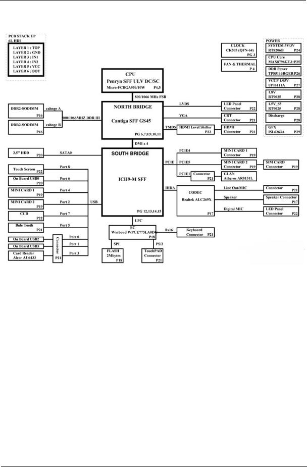
System Block Diagram
Your Notebook Tour
This section provides an overview of the features and functions of the notebook.
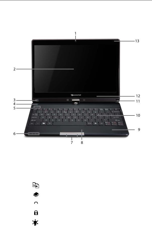
Front View
|
No. |
Icon |
Item |
Description |
||||
|
1 |
Webcam |
Web camera for video communication |
|||||
|
2 |
Display screen |
Also called Liquid-Crystal Display (LCD), displays |
|||||
|
computer output (Configuration may vary by |
|||||||
|
models). |
|||||||
|
3 |
P |
Programmable |
Launch predefined programs or user defined |
||||
|
key |
programs at the push of a button. |
||||||
|
4 |
Backup key |
Press to start automatic backup procedure. |
|||||
|
5 |
HDD |
Indicates when the hard drive is active. |
|||||
|
Num Lock |
Lights up when the Num Lock is activated. |
||||||
|
Caps Lock |
Lights up when Caps Lock is activated. |
||||||
|
6 |
Power |
Indicated the computer’s power status. |
|||||
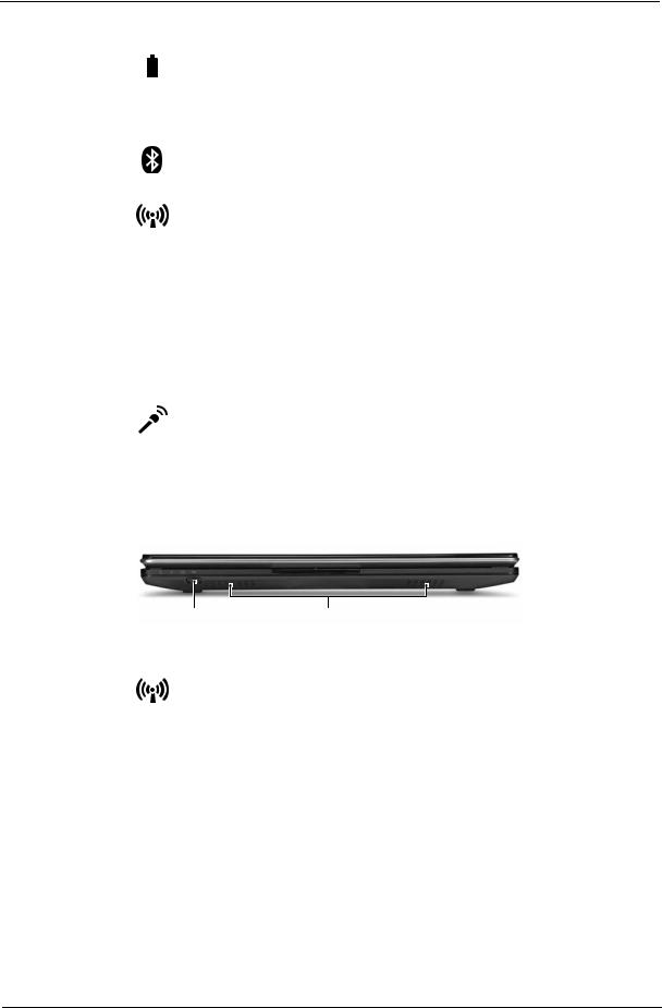
|
No. |
Icon |
Item |
Description |
||
|
Battery |
Indicates the computer’s battery status. |
||||
|
1. Charging: The light shows amber when the |
|||||
|
battery is charging. |
|||||
|
2. Fully charged: The light shows blue when in AC |
|||||
|
mode. |
|||||
|
Bluetooth |
Indicates the status of Bluetooth communication. |
||||
|
communication |
(only for certain models) |
||||
|
indicator |
|||||
|
Communication |
Indicates the status of WLAN / 3G communication. |
||||
|
indicator |
|||||
|
7 |
Click buttons (left |
The left and right buttons function like the left and |
|||
|
and right) |
right mouse buttons. |
||||
|
8 |
Touchpad |
Touch-sensitive pointing device which functions like |
|||
|
a computer mouse. |
|||||
|
9 |
Palmrest |
Comfortable support area for your hands when you |
|||
|
use the computer. |
|||||
|
10 |
Keyboard |
For entering data into your computer. |
|||
|
11 |
Stylus |
A pen tool for entering data into your computer |
|||
|
12 |
Microphone |
Internal microphone for sound recording |
|||
|
13 |
Magnetic lock |
A lock that snaps into place to prevent the screen |
|||
|
from inadvertently rotating. |
|||||
Closed Front View
|
1 |
2 |
||||
|
No. |
Icon |
Item |
Description |
||
|
1 |
Communication |
Enables / disables the WLAN / 3G functions. |
|||
|
key |
|||||
|
2 |
Speakers |
Left and right speakers deliver stereo audio |
|||
|
output. |
|||||

Left View
|
1 |
2 |
3 |
4 |
5 |
|||||||
|
No. |
Icon |
Item |
Description |
||||||||
|
1 |
External display |
Connects to a display device (e.g. external |
|||||||||
|
(VGA) port |
monitor, LCD projector). |
||||||||||
|
2 |
DC-in jack |
Connects to an AC adapter |
|||||||||
|
3 |
Ventilation slots |
Enable the computer to stay cool, even after |
|||||||||
|
prolonged use. |
|||||||||||
|
4 |
HDMI |
HDMI port |
Supports high definition digital video |
||||||||
|
connections. |
|||||||||||
|
5 |
USB 2.0 port |
Connect to USB 2.0 devices (e.g., USB mouse, |
|||||||||
|
USB camera). |
|||||||||||
Right View
|
1 |
2 |
3 |
4 |
5 |
6 |
||||
|
No. |
Icon |
Item |
Description |
||||||
|
1 |
Multi-in-1 card |
Accepts Secure Digital (SD), MultiMediaCard |
|||||||
|
reader |
(MMC), Memory Stick (MS), Memory Stick |
||||||||
|
PRO (MS PRO), xD-Picture Card (xD). |
|||||||||
|
Note: Push to remove/install the card. Only one |
|||||||||
|
card can operate at any given time. |
|||||||||
|
2 |
Headphones/ |
Connects to audio line-out devices (e.g., |
|||||||
|
speaker/line-out |
speakers, headphones). |
||||||||
|
jack with |
|||||||||
|
S/PDIF support |
|||||||||
|
Microphone-in |
Accepts inputs from external microphones. |
||||||||
|
jack |
|||||||||
|
3 |
USB 2.0 port |
Connects to USB 2.0 devices |
|||||||
|
(e.g., USB mouse, USB camera). |
|||||||||
|
4 |
Power button / |
Slide the power button to turn the computer on |
|||||||
|
indicator |
and off. / Indicates the computer’s power |
||||||||
|
status. |
|||||||||
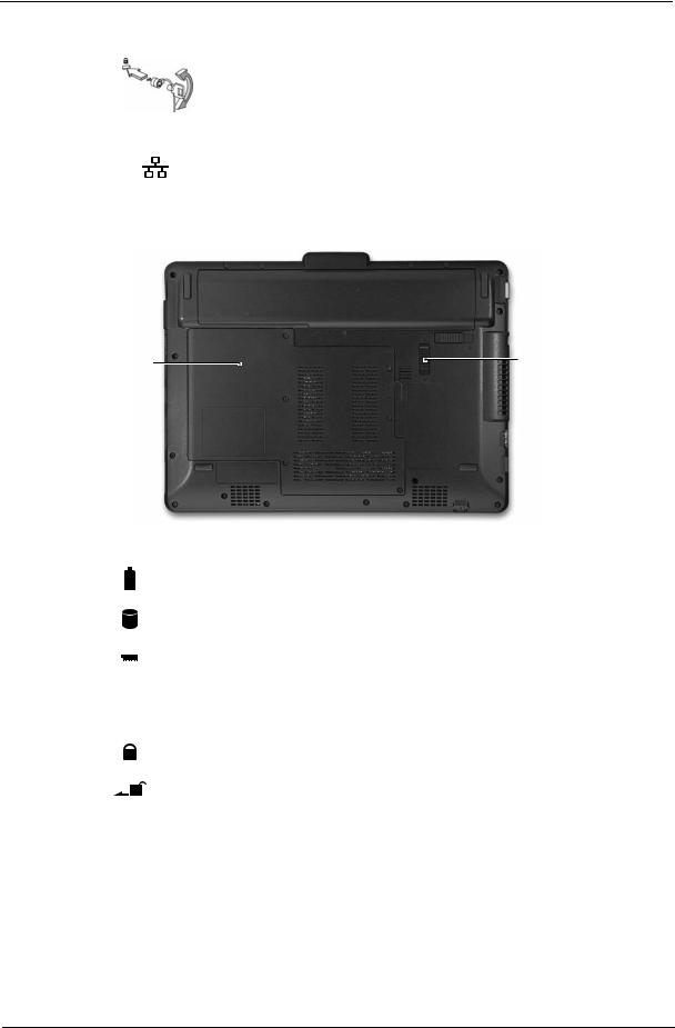
|
5 |
Kensington lock |
Connects to a Kensington-compatible |
|
|
slot |
computer security lock. |
||
|
Note: Wrap the computer security lock cable |
|||
|
around an immovable object such as a table or |
|||
|
handle of a locked drawer. Insert the lock into |
|||
|
the notch and turn the key to secure the lock. |
|||
|
Some keyless models are also available. |
|||
|
6 |
Ethernet (RJ-45) |
Connects to an Ethernet 10/100/1000-based |
|
|
port |
network. |
||
Base View
1 
 6
6
 4
4
3
|
No. |
Icon |
Item |
Description |
||||
|
1 |
Battery bay |
Houses the computer’s battery pack. |
|||||
|
2 |
Hard disk bay |
Houses the computer’s hard disk (secured with |
|||||
|
screws). |
|||||||
|
3 |
Memory |
Houses the computer’s main memory. |
|||||
|
compartment |
|||||||
|
4 |
Ventilation slots |
Enable the computer to stay cool, even after |
|||||
|
and cooling fan |
prolonged use. |
||||||
|
Note: Do not cover or obstruct the opening of the fan. |
|||||||
|
5 |
Battery lock |
Locks the battery in position. |
|||||
|
6 |
Battery release |
Releases the battery for removal. |
|||||
|
latch |
|||||||

Rear View
|
1 |
|||||
|
No. |
Icon |
Item |
Description |
||
|
1 |
Battery bay |
Houses the computer’s battery pack. |
|||
Indicators
The computer has several easy-to-read status indicators. The battery indicator is visible even when the computer cover is closed.
|
Icon |
Function |
Description |
||
|
Bluetooth |
Indicates the status of Bluetooth communication. |
|||
|
Wireless LAN |
Indicates the status of Wireless LAN/3G communication. |
|||
|
HDD |
Indicates when the hard disk drive is active. |
|||
|
Num Lock |
Lights up when Num Lock is activated. |
|||
|
Caps Lock |
Lights up when Caps Lock is activated. |
|||
|
Battery |
Indicates the computer’s battery status. |
|||
NOTE: 1. Charging: The battery light shows amber when the battery is charging. 2. Fully charged: The light shows green when in AC mode.

TouchPad Basics
The following items show you how to use the TouchPad:
1
•Move your finger across the TouchPad (1) to move the cursor.
•Press the left (2) and right (3) buttons located beneath the TouchPad to perform selection and execution functions. These two buttons are similar to the left and right buttons on a mouse. Tapping on the TouchPad is the same as clicking the left button.
|
Function |
Left Button (2) |
Right Button (3) |
Main TouchPad (1) |
|
Execute |
Quickly click twice. |
Tap twice (at the same speed |
|
|
as double-clicking a mouse |
|||
|
button). |
|||
|
Select |
Click once. |
Tap once. |
|
|
Drag |
Click and hold, then use |
Tap twice (at the same speed |
|
|
finger on the TouchPad to |
as double-clicking a mouse |
||
|
drag the cursor. |
button); rest your finger on |
||
|
the TouchPad on the second |
|||
|
tap and drag the cursor. |
|||
|
Access |
Click once. |
||
|
context menu |
|||
NOTE: When using the TouchPad, keep it — and your fingers — dry and clean. The TouchPad is sensitive to finger movement; hence, the lighter the touch, the better the response. Tapping too hard will not increase the TouchPad’s responsiveness.

Using the Keyboard
This computer has a close-to-full-sized keyboard and an embedded numeric keypad, separate cursor, lock, function and special keys.
Lock Keys and embedded numeric keypad
The keyboard has three lock keys which you can toggle on and off.
|
Lock key |
Description |
|
Caps Lock |
When Caps Lock is on, all alphabetic characters typed are in uppercase. |
|
Num Lock |
When Num Lock is on, the embedded keypad is in numeric mode. The keys |
|
<Fn> + <F11> |
function as a calculator (complete with the arithmetic operators +, -, *, and /). Use |
|
this mode when you need to do a lot of numeric data entry. A better solution |
|
|
would be to connect an external keypad. |
|
|
Scroll Lock <Fn> + |
When Scroll Lock is on, the screen moves one line up or down when you press |
|
<F12> |
the up or down arrow keys respectively. Scroll Lock does not work with some |
|
applications. |
|
The embedded numeric keypad functions like a desktop numeric keypad. It is indicated by small characters located on the upper right corner of the keycaps. To simplify the keyboard legend, cursor-control key symbols are not printed on the keys.
|
Desired access |
Num Lock on |
Num Lock off |
|
Number keys on |
Type numbers in a normal manner. |
|
|
embedded keypad |
||
|
Cursor-control keys on |
Hold <Shift> while using cursor- |
Hold <Fn> while using cursor- |
|
embedded keypad |
control keys. |
control keys. |
|
Main keyboard keys |
Hold <Fn> while typing letters on |
Type the letters in a normal |
|
embedded keypad. |
manner. |
|
![]()
Windows Keys
The keyboard has two keys that perform Windows-specific functions.
|
Key |
Description |
|||
|
Windows key |
Pressed alone, this key has the same effect as clicking on the Windows Start button; |
|||
|
it launches the Start menu. It can also be used with other keys to provide a variety of |
||||
|
functions: |
||||
|
< >: Open or close the Start menu |
||||
|
< > + <D>: Display the desktop |
||||
|
< > + <E>: Open Windows Explore |
||||
|
< > + <F>: Search for a file or folder |
||||
|
< > + <L>: Lock your computer (if you are connected to a network domain), or |
||||
|
switch users (if you’re not connected to a network domain) |
||||
|
< > + <M>: Minimizes all windows |
||||
|
< > + <R>: Open the Run dialog box |
||||
|
< > + <U>: Open Ease of Access Center |
||||
|
< > + <BREAK>: Display the System Properties dialog box |
||||
|
< > + <TAB>: Cycle through programs on the taskbar |
||||
|
<CTRL> + < > + <F>: Search for computers (if you are on a network) |
||||
|
Note: Depending on your edition of Windows 7, some shortcuts may not function as |
||||
|
described. |
||||
|
Application |
This key has the same effect as clicking the right mouse button; it opens the |
|||
|
key |
application’s context menu. |
|||
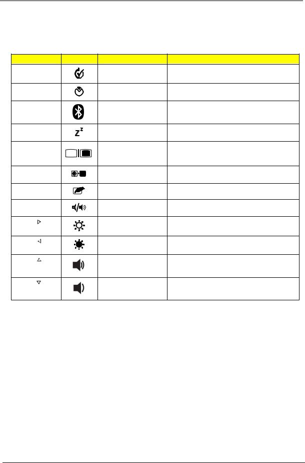
Hot Keys
The computer employs hotkeys or key combinations to access most of the computer’s controls like screen brightness and volume output.
To activate hotkeys, press and hold the <Fn> key before pressing the other key in the hotkey combination.
|
Hotkey |
Icon |
Function |
Description |
|
|
<Fn> + <F1> |
Power management |
Launch Windows power management. |
||
|
<Fn> + <F2> |
System Properties |
Display the System Properties dialog box. |
||
|
<Fn> + <F3> |
Bluetooth |
Enables/disables the Bluetooth function. |
||
|
communication switch |
||||
|
<Fn> + <F4> |
Sleep |
Puts the computer in Sleep mode. |
||
|
<Fn> + <F5> |
Display toggle |
Switches display output between the display |
||
|
screen, external monitor (if connected) and |
||||
|
both. |
||||
|
<Fn> + <F6> |
Screen blank |
Turns the display screen backlight off to save |
||
|
power. Press any key to return. |
||||
|
<Fn> + <F7> |
Touchpad toggle |
Turns the internal touchpad on and off. |
||
|
<Fn> + <F8> |
Speaker toggle |
Turns the speakers on and off. |
||
|
<Fn> + < |
> |
Brightness up |
Increases the screen brightness. |
|
|
<Fn> + < |
> |
Brightness down |
Decreases the screen brightness. |
|
|
<Fn> + < |
> |
Volume up |
Increases the sound volume. |
|
|
<Fn> + < |
> |
Volume down |
Decreases the sound volume. |

Special Keys
You can locate the Euro symbol and the US dollar sign at the upper-center and/or bottom-right of your keyboard.
The Euro symbol
1.Open a text editor or word processor.
2.Hold <Alt Gr> and then press the <5> key at the upper-center of the keyboard.
NOTE: Some fonts and software do not support the Euro symbol. See www.microsoft.com/typography/faq/ faq12.htm for more information.
The US dollar sign
1.Open a text editor or word processor.
2.Hold <Shift> and then press the <4> key at the upper-center of the keyboard. NOTE: This function varies according to the language settings.

Hardware Specifications and Configurations
Processor
|
Item |
Specification |
||||||||||||||
|
CPU type |
Intel Penryn SFF (ULV) |
||||||||||||||
|
CPU package |
Micro-FCBGA 956 balls |
||||||||||||||
|
Features |
• Supports Intel architecture with Dynamic execution. |
||||||||||||||
|
• On-die, primary 32-kB instruction cache and 32-kB write-back |
|||||||||||||||
|
data cache. |
|||||||||||||||
|
• On-die, up to 3MB second level shared cache with advanced |
|||||||||||||||
|
transfer cache architecture. |
|||||||||||||||
|
• Streaming SIMD Extensions 2 (SSE2),Streaming SIMD |
|||||||||||||||
|
Extensions 3 (SSE3) |
|||||||||||||||
|
• Supplemental streaming SIMD extensions 3 (SSSE3) and |
|||||||||||||||
|
SSE4.1 instruction sets. |
|||||||||||||||
|
• 800MHz source-synchronous front side bus (FSB) |
|||||||||||||||
|
• Advanced power management features including Enhanced |
|||||||||||||||
|
Intel SpeedStep® |
|||||||||||||||
|
• Technology and dynamic FSB frequency switching. |
|||||||||||||||
|
• Digital thermal sensor (DTS). |
|||||||||||||||
|
• Execute disable bit support for enhanced security. |
|||||||||||||||
|
• Intel® Dynamic Acceleration Technology and Enhanced Multi |
|||||||||||||||
|
Threaded |
|||||||||||||||
|
• Thermal Management (EmTTM). |
|||||||||||||||
|
• Support enhanced Intel Virtualization Technology. |
|||||||||||||||
|
Core Logic |
• Mobile Intel® GS45 Express Chipset |
||||||||||||||
|
Processor Specifications |
|||||||||||||||
|
Item |
CPU |
Cores |
Cache |
Package |
Core |
Acer P/N |
|||||||||
|
Speed |
Size |
Voltage |
|||||||||||||
|
SU7300 |
1.4GHz |
1 |
3MB |
Micro-FCBGA 956 |
1.050V- |
C2DSU7300B |
|||||||||
|
balls |
1.150V |
||||||||||||||
|
SU4100 |
1.3GHz |
2 |
2MB |
Micro-FCBGA 956 |
1.050V- |
PMDSU4100B |
|||||||||
|
balls |
1.150V |
||||||||||||||
|
SU2300 |
1.2GHz |
2 |
1MB |
Micro-FCBGA 956 |
1.050V- |
CMSU2300B |
|||||||||
|
balls |
1.150V |
||||||||||||||
|
CPU Fan True Value Table |
|||||||||||||||
|
CPU Temperature |
Fan Speed (RPM) |
SPL Spec (dBA) |
|||||||||||||
|
(Celsius) |
|||||||||||||||
|
38 |
2400 |
On |
|||||||||||||
|
43 |
3300 |
26 |
|||||||||||||
|
49 |
4000 |
29 |
|||||||||||||
|
56 |
4500 |
31 |
|||||||||||||
|
Throttling 50%: On = 88°C; Off = 85°C |
|||||||||||||||
|
EC shut down at 95°C; H/W shut down at 98°C |
|||||||||||||||
|
North Bridge Specifications |
|||||||||||||||
|
Item |
Specification |
||||||||||||||
|
Chipset |
Intel Crestline GS45 SFF |
||||||||||||||
|
Package |
FCBGA 1363 balls |
||||||||||||||

|
Item |
Specification |
|||||||||||
|
Features |
• Processor host bus supports 667/800/1066Mhz FSB support. |
|||||||||||
|
• Supports Dual Channel DDR3 SD-RAM at 800/1066MHz. |
||||||||||||
|
• Integrated SDRAM controller up to *GB (2 SODIMM support) |
||||||||||||
|
• DMI x2 and DMI x4 for connection between GMCH and |
||||||||||||
|
ICH9M. |
||||||||||||
|
South Bridge Specifications |
||||||||||||
|
Item |
Specification |
|||||||||||
|
Chipset |
ICH9M SFF |
|||||||||||
|
Package |
BGA 676 balls |
|||||||||||
|
Features |
• Upstream accelerated Hub architecture interface for access to |
|||||||||||
|
GMCH. |
||||||||||||
|
• PCI Express Base Specification, Revision 1.1 support. |
||||||||||||
|
• PCI 2.3 interface. (4 PCI Request/Grant pairs). |
||||||||||||
|
• |
ACPI Power Management Logic Support. Enhanced DMA |
|||||||||||
|
controller, interrupt controller, timers functions. |
||||||||||||
|
• Integrated Serial ATA host controllers with independent DMA |
||||||||||||
|
operation on six ports and AHCI support. |
||||||||||||
|
• USB 1.1 & USB 2.0 Host controllers. |
||||||||||||
|
• Supports Intel High Definition Audio (Intel HD Audio) Interface. |
||||||||||||
|
• Supports Intel® Matrix Storage Technology. |
||||||||||||
|
• Supports Intel® Active Management Technology. |
||||||||||||
|
• Low Pin Count (LPC) interface. |
||||||||||||
|
• |
6 PCIe ports. |
|||||||||||
|
System Memory |
||||||||||||
|
Item |
Specification |
|||||||||||
|
Memory size |
0MB (No on-board Memory) |
|||||||||||
|
DIMM socket number |
2 sockets |
|||||||||||
|
Supports memory size per socket |
2GB |
|||||||||||
|
Supports maximum memory size |
4GB for 64bit OS (with two 2GB SO-DIMM) |
|||||||||||
|
Supports DIMM type |
DDR3 Synchronous DRAM |
|||||||||||
|
Supports DIMM Speed |
800 MHz |
|||||||||||
|
Supports DIMM voltage |
1.5V |
|||||||||||
|
Supports DIMM package |
204-pin DDR3-800 SO-DIMM |
|||||||||||
|
Module Combination |
Any combination permissible within the above specifications. |
|||||||||||
|
Hard Disk Drive Interface |
||||||||||||
|
Item |
Specifications |
|||||||||||
|
Vendor & |
Hitachi |
Hitachi |
Hitachi |
Hitachi |
Hitachi |
Hitachi |
||||||
|
Model |
HTS545050B |
HTS545032B |
HTS545025B |
HTS545016B |
HTS543225L |
HTS543216L9 |
||||||
|
Name |
9A300 |
9A300 |
9A300 |
9A300 |
9A300 |
SA00 |
||||||
|
Capacity |
500 |
320 |
250 |
160 |
250 |
160 |
||||||
|
(GB) |
||||||||||||
|
Bytes per |
512 |
|||||||||||
|
sector |
||||||||||||
|
Data heads |
4 |
3 |
2 |
2 |
3 |
2 |
||||||
|
Drive Format |
||||||||||||

|
Item |
Specifications |
||||||||
|
Disks |
2 |
2 |
1 |
1 |
2 |
1 |
|||
|
Spindle |
5400 |
||||||||
|
speed |
|||||||||
|
(RPM) |
|||||||||
|
Performance Specifications |
|||||||||
|
Buffer size |
8MB |
||||||||
|
Interface |
SATA |
||||||||
|
Internal |
3GB/s maximum |
1.5GB/s |
|||||||
|
transfer |
maximum |
||||||||
|
rate (Gbits/ |
|||||||||
|
sec., max) |
|||||||||
|
I/O data |
875 Mbits/s maximum |
845 Mbits/s |
775Mbits/s |
729Mbits/s |
|||||
|
transfer |
maximum |
maximum |
maximum |
||||||
|
rate |
|||||||||
|
(Mbytes/ |
|||||||||
|
sec max) |
|||||||||
|
DC Power Requirements |
|||||||||
|
Voltage |
+5.0V ± 5%. |
||||||||
|
Item |
Specifications |
||||
|
Vendor & Model |
Toshiba |
Toshiba |
Toshiba |
Toshiba |
|
|
Name |
MK1655GSX |
MK2555GSX |
MK3255GSX |
MK5055GSX |
|
|
Capacity (GB) |
160 |
250 |
320 |
500 |
|
|
Bytes per sector |
512 |
512 |
512 |
512 |
|
|
Data heads |
2 |
2 |
4 |
4 |
|
|
Drive Format |
|||||
|
Disks |
1 |
1 |
2 |
2 |
|
|
Spindle speed |
5400 |
||||
|
(RPM) |
|||||
|
Performance Specifications |
|||||
|
Buffer size |
8MB |
||||
|
Interface |
SATA |
||||
|
Internal transfer |
363 ~ 952 typical |
||||
|
rate (Mbits/sec, |
|||||
|
max) |
|||||
|
I/O data transfer |
300 |
||||
|
rate |
|||||
|
(Mbytes/sec |
|||||
|
max) |
|||||
|
DC Power Requirements |
|||||
|
Voltage |
5V ±5% |
||||
|
Item |
Specifications |
||||
|
Vendor & Model |
Western Digital |
Western Digital |
Western Digital |
Western Digital |
|
|
Name |
WD1600BEVT- |
WD2500BEVT-22ZCT0 |
WD3200BEVT-22ZCT0 |
WD5000BEVT-22ZAT0 |
|
|
22ZCTO |
|||||
|
Capacity (GB) |
160 |
250 |
320 |
500 |
|
|
Bytes per sector |
512 |
||||
|
Data heads |
2 |
4 |
3 |
4 |
|

|
Item |
Specifications |
||||||||||
|
Drive Format |
|||||||||||
|
Disks |
1 |
2 |
2 |
2 |
|||||||
|
Spindle speed |
5400 |
||||||||||
|
(RPM) |
|||||||||||
|
Performance Specifications |
|||||||||||
|
Buffer size |
8 MB |
||||||||||
|
Interface |
SATA |
||||||||||
|
Internal transfer |
N/A |
||||||||||
|
rate (Mbits/sec, |
|||||||||||
|
max) |
|||||||||||
|
I/O data transfer |
300 |
||||||||||
|
rate |
|||||||||||
|
(Mbytes/sec |
|||||||||||
|
max) |
|||||||||||
|
DC Power Requirements |
|||||||||||
|
Voltage |
5V ±5% |
||||||||||
|
BIOS |
|||||||||||
|
Item |
Specification |
||||||||||
|
BIOS vendor |
Insyde |
||||||||||
|
BIOS ROM type |
W25X16AVSSIG |
||||||||||
|
BIOS ROM size |
16Mb |
||||||||||
|
BIOS package |
8 PIN SOIC |
||||||||||
|
Supported Protocols |
SPI |
||||||||||
|
BIOS password control |
Set by setup manual |
||||||||||
|
LCD 11.6” |
|||||||||||
|
Item |
Specifications |
||||||||||
|
Vendor/model name |
AUO |
Chi Mei |
LG |
Samsung |
|||||||
|
B116XW02 |
N116B6-L02 |
LP116WH1 |
LTN116AT01- |
||||||||
|
A01 |
|||||||||||
|
Screen Diagonal (mm) |
293.83 |
||||||||||
|
Active Area (mm) |
256.125 (H) x 144.00 (V) |
||||||||||
|
Display resolution (pixels) |
1366×3(RGB) x 768 |
||||||||||
|
Pixel Pitch (mm) |
0.1875 x 0.1875 |
0.2265(H) x |
|||||||||
|
0.2265(V) |
|||||||||||
|
Typical White Luminance (cd/m2) |
200 typ. (5 points average) |
||||||||||
|
also called Brightness |
|||||||||||
|
Contrast Ratio |
500:1 typ |
||||||||||
|
Response Time (Optical Rise |
8 typ / 16 |
8 typ / 16 Max |
9 typ / 16 max |
16 typ / 25 |
|||||||
|
Time/Fall Time) msec |
Max |
max |
|||||||||
|
Typical Power Consumption |
4.0 max. |
N/A |
3.18 W Typ. |
N/A |
|||||||
|
(watt) |
(Include |
||||||||||
|
Logic and |
|||||||||||
|
Blu power) |
|||||||||||
|
Weight (without inverter) |
255g max. |
240g max |
255g max. |
||||||||
|
Physical Size (mm) |
268L x 161.5W x 5.0T |
||||||||||

|
Item |
Specifications |
|||||||||||
|
Electrical Interface |
1 channel |
3.3V LVDS |
LVDS |
LVDS |
||||||||
|
LVDS |
||||||||||||
|
Viewing Angle (degree) |
||||||||||||
|
Horizontal (Right) / (Left) |
45/45 |
45/45 |
30/30 |
45/45 |
||||||||
|
Vertical (Upper) / (Lower) |
10/30 |
20/45 |
10/20 |
15/35 |
||||||||
|
Bluetooth |
||||||||||||
|
Item |
Specification |
|||||||||||
|
Bluetooth Controller |
Foxconn T60H928.33 |
|||||||||||
|
Features |
• Fully Qualified Bluetooth v2.1 with Class 2 specification RF output |
|||||||||||
|
power. |
||||||||||||
|
• Enhanced Data Rate (EDR) compliant. |
||||||||||||
|
• Full Piconet and Scatternet operation. |
||||||||||||
|
• Integrated PIFA Antenna with better RF performance. |
||||||||||||
|
• USB 2.0 compliant interface. |
||||||||||||
|
• F/W upgradable via Flash downloads. |
||||||||||||
|
• Very low power consumption. |
||||||||||||
|
• Support Coexistence with Intel WCS (Wireless Coexistence System) |
||||||||||||
|
& AFH (Adaptive Frequency Hopping) |
||||||||||||
|
Radio Technology |
FHSS |
|||||||||||
|
Operating Frequency |
2.402GHz ~ 2.480GHz |
|||||||||||
|
Channel Numbers |
79 channels with 1MHz BW |
|||||||||||
|
Transmitter Output Power |
-6~4dBm output power for BT class 2 operation |
|||||||||||
|
Coverage |
10m (Varies depending on operating environment) |
|||||||||||
|
Receiver Sensitivity |
-75dBm, BER<0.1% |
|||||||||||
|
Maximum Receiver Signal |
-10dBm |
|||||||||||
|
Operating Voltage |
3.3V+/-0.3V |
|||||||||||
|
Working Temperature |
Operating temp: 0 °C to +70 °C (+32 °F to +158 °F) |
|||||||||||
|
Non-operating temp: -10 °C to +75°C (+14 °F to +167 °F) |
||||||||||||
|
Interface |
USB2.0 with JST SM08B-SURS-TF connector |
|||||||||||
|
Weight |
1.75g |
|||||||||||
|
Audio Interface |
||||||||||||
|
Item |
Specification |
|||||||||||
|
Codec Controller |
Realtek ALC269X |
|||||||||||
|
Compatibility |
• |
Headphone-out |
||||||||||
|
• S/PDIF, Line-In and Microphone-In. |
||||||||||||
|
• 2 stereo ADCs support 16/20/24-bit PCM format recording simultaneously. |
||||||||||||
|
Sampling Rate |
• All DACs supports 16/20/24-bit, 44.1k/48k/96k/192kHz sample rate. |
|||||||||||
|
• Two independent S/PDIF-OUT converters support 16/20/24-bit, 44.1k/48k/ |
||||||||||||
|
88.2k/96k/192kHz sample rate. One for normal S/PDIF output, the other one |
||||||||||||
|
output an independent digital stream to HDMI transmitter. |
||||||||||||
|
Internal |
• Digital MICRO PHONE ZK2(HFM-M101-006-L19-G) |
|||||||||||
|
Microphone |
• |
Digital MICRO PHONE ZK2(A-OA2408FM-018) |
||||||||||
|
Internal Speakers |
• Two Med-High Speakers (1W/4Ù) |
|||||||||||

LAN Interface
|
Item |
Specification |
||||
|
LAN Chipset |
Atheros AR8131L |
||||
|
Package |
48pin QFN |
||||
|
Features |
• |
It is an ultra-high performance, ultralow cost, and ultra- |
|||
|
low power fully integrated 10/100/1000 Mbps NIC/LOM |
|||||
|
Ethernet. |
|||||
|
• The AR8131L combines a 10/100/1000BASE-T GbE |
|||||
|
media access controller (MAC), a triplespeed Ethernet |
|||||
|
physical layer transceiver (PHY), and a PCI Express bus |
|||||
|
interface. |
|||||
|
• The AR8131L is compliant with IEEE 802.3u |
|||||
|
specification for 10/100 Mbps Ethernet and IEEE |
|||||
|
802.3ab specification for 1000 Mbps Ethernet. |
|||||
|
• The AR8131L device combines pulse shaping, Tx/Rx |
|||||
|
PCS, echo canceller, NEXT canceller, equalizer, |
|||||
|
decoder, and timing recovery functions to deliver robust |
|||||
|
signal performance in noisy environments. |
|||||
|
• The AR8131L GbE controller supports checksum off-load |
|||||
|
features for IP, TCP, and UDP, lowering CPU utilization |
|||||
|
and optimizing network performance. |
|||||
|
Keyboard |
|||||
|
Item |
Specification |
||||
|
Keyboard Controller |
Winbond WPCE775LA0DG |
||||
|
Total number of keypads |
US: 86 |
||||
|
UK: 86 |
|||||
|
UI: 86 |
|||||
|
GERMAN: 86 |
|||||
|
Windows logo key |
Yes |
||||
|
Internal & external keyboard work |
Plug USB keyboard to the USB port directly: Yes |
||||
|
simultaneously |
|||||
|
Features |
• Plug USB keyboard to the USB port directly: Yes |
||||
|
Media Card Reader |
|||||
|
Item |
Specification |
||||
|
Chipset |
Alcor AU6433 |
||||
|
Features |
• |
Fully compatible with USB2.0 High Speed and backward |
|||
|
compatible with USB1.1 specifications |
|||||
|
• Supports multiple flash card interfaces, including SD/ |
|||||
|
MMC/xD/MS. |
|||||
|
• |
Supports single LUN |
||||
|
• |
48-pin LQFP |
||||

|
Item |
Specification |
||
|
Compliance |
• |
Complies with USB Device Class Definition for Mass |
|
|
Storage and Bulk-Transport V1.0 |
|||
|
• |
Complies with Secure Digital Card (SD) specification up |
||
|
to ver. 2.0(SDHC) |
|||
|
• |
Complies with MultiMedia Card (MMC) specification up |
||
|
to ver. 4.2 |
|||
|
• |
Complies with Memory Stick (MS) specification up to ver. |
||
|
1.43 |
|||
|
• Complies with Memory Stick PRO (MS_Pro) specification |
|||
|
up to ver. 1.03 |
|||
|
• |
Complies with Memory Stick PRO-HG (MS PRO-HG) |
||
|
specification up to ver. 1.01 |
|||
|
• |
Complies with Memory Stick Interface Guideline for PC |
||
|
peripheral devices with Memory Stick Slot ver. 1.16-00 |
|||
|
• |
Complies with xD-Picture Card (xD) specification up to |
||
|
version 1.2 |
|||
|
Interface |
• |
USB 2.0 |
|
|
Power |
• |
3.3V |
|
|
Camera |
|
Item |
Specifications |
||||||||||||||
|
Vendor and model |
Chicony CNF9011/9048 |
Lite-on 09P2SF001 |
Suyin CN0316-S30C- |
||||||||||||
|
OV06-1 |
|||||||||||||||
|
Interface |
USB 2.0 |
||||||||||||||
|
Optical aperture |
N/A |
||||||||||||||
|
Focusing range |
17.4 cm — infinity |
19 CM — infinity |
40 CM — infinity |
||||||||||||
|
Dimensions (L x W x H |
68 X 8 X 3.64 mm |
68 X 8 X 3.84 mm |
65 X 7.9 X 3.8 mm |
||||||||||||
|
mm) |
|||||||||||||||
|
Sensor type |
CMOS |
||||||||||||||
|
Pixel resolution |
640X480 |
||||||||||||||
|
Wireless LAN |
|||||||||||||||
|
Item |
Specification |
Specification |
Specification |
Specification |
|||||||||||
|
Manufacturer |
Foxconn |
Foxconn |
Intel |
Intel |
|||||||||||
|
Type |
Atheros AR9283 |
T77H121.01 |
WiFi Link 1000 |
Shirley Peak |
|||||||||||
|
PHY Mode |
b,g,n. |
b,g,n. |
b, g, n. |
a, b, g, n. |
|||||||||||
|
Supported |
|||||||||||||||
|
Item |
Specification |
Specification |
|||||||||||||
|
Manufacturer |
Intel |
Lite-on |
|||||||||||||
|
Type |
Wifi Link 5000 |
Atheros AR5B93 |
|||||||||||||
|
PHY Modes |
a, b, g, n. |
b, g, n. |
|||||||||||||
|
Supported |
|||||||||||||||
|
3G Module |
|||||||||||||||
|
Item |
Specifications |
||||||||||||||
|
3G Module |
• |
Qualcomm Gobi1000 |
|||||||||||||
|
• |
Huawei EM770W |
||||||||||||||
|
Technical |
GSM / GPRS/ EGPRS MSC 12 / DTM Item/ WCDMA R5 / HSDPA 7.2Mbps / HSUPA |
||||||||||||||
|
Standard |
5.76Mbps |
||||||||||||||
![]()
|
Item |
Specifications |
||
|
Interface |
USB 2.0 |
||
|
Antenna |
1 x 2 |
||
|
Embedded Controller |
|||
|
Item |
Specifications |
||
|
Chipset |
Winbond WPCE775LA0DG |
||
|
Features |
• Shared SPI BIOS flash memory with page programming support. |
•High-accuracy, high-speed ADC.
•Up to 95 GPIO ports (including keyboard scanning) with a variety of wake-up events (up to 42 wake-up inputs).
•16-bit RISC core, with up to 4 Mbytes of external address space, running at up to 25 MHz.
•128-pin LQChipFP
Battery
|
Item |
Specifications |
|
|
6 Cell |
||
|
Vendor & model name |
SIMPLO UM09F70 3S2P |
|
|
SANYO UM09F36 3S2P |
||
|
Battery Type |
Li-ion |
|
|
Pack capacity |
SANYO 6 cell 5600mAh |
|
|
SAMSUNG 6 cell 5600mAh |
||
|
LGC 6 cell 5600mAh |
||
|
Number of battery cell |
6 |
|
|
Package configuration |
3 cells in series, 2 series in |
|
|
parallel |
||
|
Normal voltage |
11.1 |
|
|
Charge voltage |
12.6 |
|


Chapter 2
System Utilities
BIOS Setup Utility
The BIOS Setup Utility is a hardware configuration program built into your computer’s BIOS (Basic Input/ Output System).
Your computer is already properly configured and optimized, and you do not need to run this utility. However, if you encounter configuration problems, you may need to run Setup. Please also refer to Chapter 4 Troubleshooting when problem arises.
To activate the BIOS Utility, press F2 during POST (when Press <F2> to enter Setup message is prompted on the bottom of screen).
Press F2 to enter setup. The default parameter of F12 Boot Menu is set to “disabled”. If you want to change boot device without entering BIOS Setup Utility, please set the parameter to “enabled”.
Press <F12> during POST to enter multi-boot menu. In this menu, user can change boot device without entering BIOS SETUP Utility.
Navigating the BIOS Utility
There are six menu options: Information, Main, Advanced, Security, Power, Boot, and Exit. Follow these instructions:
•To choose a menu, use the left and right arrow keys.
•To choose an item, use the up and down arrow keys.
•To change the value of a parameter, press F5 or F6.
•A plus sign (+) indicates the item has sub-items. Press Enter to expand this item.
•Press Esc while you are in any of the menu options to go to the Exit menu.
•In any menu, you can load default settings by pressing F9. You can also press F10 to save any changes made and exit the BIOS Setup Utility.
NOTE: You can change the value of a parameter if it is enclosed in square brackets. Navigation keys for a particular menu are shown on the bottom of the screen. Help for parameters are found in the Item Specific Help part of the screen. Read this carefully when making changes to parameter values. Please note that system information is subject to different models.

Information
The Information screen displays a summary of your computer hardware information.
|
InsydelH20 Setup Utility |
Rev. 3.5 |
||||||||||||
|
Information |
Main |
Security |
Boot |
Exit |
|||||||||
|
CPU Type: |
Genuine Intel (R) CPU |
U2300 |
|||||||||||
|
CPU Speed: |
1.20GHz |
||||||||||||
|
IDE 0 Model Name: |
TOSHIBA MK2555GSX |
||||||||||||
|
IDE 0 Serial Number: |
89IBP6AKT |
||||||||||||
|
ATAPI Model Name: |
None |
||||||||||||
|
System BIOS Version: |
v0.2103 |
||||||||||||
|
VGA BIOS Version: |
Intel V1800 |
||||||||||||
|
Serial Number: |
ZE80SK01C191A0792500 |
||||||||||||
|
Asset Tag Number: |
20202 |
||||||||||||
|
Product Name: |
|||||||||||||
|
Manufacturer Name : |
Acer |
||||||||||||
|
UUID: |
A570A794A5554A0BABFDC44254EFC55F |
||||||||||||
|
F1 |
Help |
Select |
Item |
F5/F6 |
Change Values |
F9 |
Setup |
Default |
|||||
|
Es c |
Exit |
Select |
Menu |
Enter |
Select |
Sub-Menu |
F10 |
Save |
and Exit |
NOTE: The system information is subject to different models.
|
Parameter |
Description |
|
CPU Type |
This field shows the CPU type and speed of the system. |
|
CPU Speed |
This field shows the speed of the CPU. |
|
HDD Model Name |
This field shows the model name of HDD installed on primary IDE master. |
|
HDD Serial Number |
This field displays the serial number of HDD installed on primary IDE master. |
|
ATAPI Model Name |
This field displays the model name of the installed ODD drive. |
|
System BIOS Version |
Displays system BIOS version. |
|
VGA BIOS Version |
This field displays the VGA firmware version of the system. |
|
Serial Number |
This field displays the serial number of this unit. |
|
Asset Tag Number |
This field displays the asset tag number of the system. |
|
Product Name |
This field shows product name of the system. |
|
Manufacturer Name |
This field displays the manufacturer of this system. |
|
UUID Number |
Universally Unique Identifier (UUID) is an identifier standard used in software |
|
construction, standardized by the Open Software Foundation (OSF) as part of |
|
|
the Distributed Computing Environment (DCE). |
|

Main
The Main screen allows the user to set the system time and date as well as enable and disable boot option and recovery.
|
InsydelH20 Setup Utility |
Rev. 3.5 |
|||
|
Information |
Main |
Security |
Boot |
Exit |
|
System Time |
[13:52:10] |
|
System Date |
[10/06/2009] |
|
Total Memory |
2048 MB |
|
Video Memory: |
[64MB] |
|
Quiet Boot |
[Enabled] |
|
Network Boot |
[Enabled] |
|
F12 Boot Menu |
[Disabled] |
|
D2D Recovery |
[Enabled] |
|
SATA Mode |
[AHCI Mode] |
Item Specific Help
This is the help for the hour field. Valid range is from 0 to 23. REDUCE / INCREASE : F5/F6
|
F1 |
Help |
Select |
Item |
F5/F6 |
Change |
Values |
F9 |
Setup |
Default |
|
Es c |
Exit |
Select |
Menu |
Enter |
Select |
Sub-Menu |
F10 |
Save |
and Exit |
NOTE: The screen above is for your reference only. Actual values may differ.
The table below describes the parameters in this screen. Settings in boldface are the default and suggested parameter settings.
|
Parameter |
Description |
Format/Option |
|
System Time |
Sets the system time. The hours are displayed with 24- |
Format: HH:MM:SS |
|
hour format. |
(hour:minute:second) |
|
|
System Date |
Sets the system date. |
Format MM/DD/YYYY |
|
(month/day/year) |
||
|
Total Memory |
This field reports the memory size of the system. |
N/A |
|
Memory size is fixed to 2048 MB. |
||
|
Video Memory |
Shows the video memory size. VGA Memory size=32 MB |
N/A |
|
Quick Boot |
Allows startup to skip certain tests while booting, |
Option: Enabled or Disabled |
|
decreasing the time needed to boot the system. |
||
|
Network Boot |
Enables, disables the system boot from LAN (remote |
Option: Enabled or Disabled |
|
server). |
||
|
F12 Boot Menu |
Enables, disables Boot Menu during POST. |
Option: Enabled or Enabled |
|
D2D Recovery |
Enables, disables D2D Recovery function. The function |
Option: Enabled or Disabled |
|
allows the user to create a hidden partition on hard disc |
||
|
drive to store operation system and restore the system |
||
|
to factory defaults. |
||
|
SATA Mode |
Control the mode in which the SATA controller should |
Option: AHCI or IDE |
|
operate. |

Security
The Security screen contains parameters that help safeguard and protect your computer from unauthorized use.
|
InsydelH20 Setup Utility |
Rev. 3.5 |
|||
|
Information |
Main |
Security |
Boot |
Exit |
|
Supervisor Password Is : |
Clear |
|
User Password Is : |
Clear |
|
HDD Password Is : |
Clear |
|
Set Supervisor Password |
|
|
Set User Password |
|
|
Set Hdd Password |
|
|
Power on password |
[Disabled] |
Item Specific Help
Install or Change the password and the length of password must be greater than one word.
|
F1 |
Help |
Select |
Item |
F5/F6 |
Change |
Values |
F9 |
Setup |
Default |
|
Es c |
Exit |
Select |
Menu |
Enter |
Select |
Sub-Menu |
F10 |
Save |
and Exit |
The table below describes the parameters in this screen. Settings in boldface are the default and suggested parameter settings.
|
Parameter |
Description |
Option |
|
Supervisor Password Is |
Shows the setting of the Supervisor password |
Clear or Set |
|
User Password Is |
Shows the setting of the user password. |
Clear or Set |
|
Set Supervisor Password |
Press Enter to set the supervisor password. When |
|
|
set, this password protects the BIOS Setup Utility |
||
|
from unauthorized access. The user can not either |
||
|
enter the Setup menu nor change the value of |
||
|
parameters. |
||
|
Set User Password |
Press Enter to set the user password. When user |
|
|
password is set, this password protects the BIOS |
||
|
Setup Utility from unauthorized access. The user can |
||
|
enter Setup menu only and does not have right to |
||
|
change the value of parameters. |
||
|
Set Hdd Password |
Enter HDD password. |
|
|
Power on password |
Defines whether a password is required or not while |
Enabled or |
|
the events defined in this group happened. The |
Disabled |
|
|
following sub-options are all requires the Supervisor |
||
|
password for changes and should be grayed out if the |
||
|
user password was used to enter setup. |
||
NOTE: When you are prompted to enter a password, you have three tries before the system halts. Don’t forget your password. If you forget your password, you may have to return your notebook computer to your dealer to reset it.

Setting a Password
Follow these steps as you set the user or the supervisor password:
1.Use the ↑ and ↓ keys to highlight the Set Supervisor Password parameter and press the Enter key. The Set Supervisor Password box appears:
Set Supervisor Password
|
Enter |
New |
Password |
[ |
] |
|
|
Confirm |
New |
Password |
[ |
] |
2.Type a password in the “Enter New Password” field. The password length can not exceeds 8 alphanumeric characters (A-Z, a-z, 0-9, not case sensitive). Retype the password in the “Confirm New Password” field.
IMPORTANT:Be very careful when typing your password because the characters do not appear on the screen.
3.Press Enter. After setting the password, the computer sets the User Password parameter to “Set”.
4.If desired, you can opt to enable the Password on boot parameter.
5.When you are done, press F10 to save the changes and exit the BIOS Setup Utility.
Removing a Password
Follow these steps:
1.Use the ↑ and ↓ keys to highlight the Set Supervisor Password parameter and press the Enter key. The Set Password box appears:
Set Supervisor Password
|
Enter Current Password |
[ |
] |
|
|
Enter New Password |
[ |
] |
|
|
Confirm New Password |
[ |
] |
2.Type the current password in the Enter Current Password field and press Enter.
3.Press Enter twice without typing anything in the Enter New Password and Confirm New Password fields. The computer then sets the Supervisor Password parameter to “Clear”.
4.When you have changed the settings, press u to save the changes and exit the BIOS Setup Utility.

Changing a Password
1.Use the ↑ and ↓ keys to highlight the Set Supervisor Password parameter and press the Enter key. The Set Password box appears.
Set Supervisor Password
|
Enter Current Password |
[ |
] |
|
|
Enter New Password |
[ |
] |
|
|
Confirm New Password |
[ |
] |
2.Type the current password in the Enter Current Password field and press Enter.
3.Type a password in the Enter New Password field. Retype the password in the Confirm New Password field.
4.Press Enter. After setting the password, the computer sets the User Password parameter to “Set”.
5.If desired, you can enable the Password on boot parameter.
6.When you are done, press F10 to save the changes and exit the BIOS Setup Utility.
If the verification is OK, the screen will display as following.
Setup Notice
Changes have been saved.
[Continue]
The password setting is complete after the user presses Enter.
If the current password entered does not match the actual current password, the screen will show you the Setup Warning.
Setup Warning
Invalid Password.
[Continue]
If the new password and confirm new password strings do not match, the screen displays the following message.
Setup Warning
Passwords do not match. Re-enter password.
[Continue]

Boot
This menu allows the user to decide the order of boot devices to load the operating system. Bootable devices includes the USB diskette drives, the onboard hard disk drive and the DVD drive in the module bay.
|
InsydelH20 Setup Utility |
Rev. 3.5 |
|||
|
Information |
Main |
Security |
Boot |
Exit |
Boot priority order :
1.IDE0 : TOSHIBA MK2555GSX
2.IDE1 :
3.Network Boot : Atheros Boot Agent
4.USB HDD :
5.USB CDROM :
6.USB FDD :
Item Specific Help
Use < > or <
 > to select a device, then press <F6> to move it up the list, or <F5> to move it down the list. Press
<Esc> to escape the menu
|
F1 |
Help |
Select |
Item |
F5/F6 |
Change |
Values |
F9 |
Setup |
Default |
|
Es c |
Exit |
Select |
Menu |
Enter |
Select |
Sub-Menu |
F10 |
Save |
and Exit |
Follow the on-screen instructions to adjust the order in which the devices boot.

Exit
The Exit screen allows you to save or discard any changes you made and quit the BIOS Utility.
|
InsydelH20 Setup Utility |
Rev. |
3.5 |
||||||||
|
Information |
Main |
Security |
Boot |
Exit |
||||||
|
Exit Saving Changes |
Item Specific Help |
|||||||||
|
Exit Discarding Changes |
||||||||||
|
Load Setup Defaults |
Exit system setup and |
|||||||||
|
Discard Changes |
||||||||||
|
save your changes. |
||||||||||
|
Save Changes |
||||||||||
|
F1 |
Help |
Select |
Item |
F5/F6 |
Change |
Values |
F9 |
Setup |
Default |
|
|
Es c |
Exit |
Select |
Menu |
Enter |
Select |
Sub-Menu |
F10 |
Save |
and Exit |
The table below describes the parameters in this screen.
|
Parameter |
Description |
|
Exit Saving Changes |
Exit System Setup and save your changes to CMOS. |
|
Exit Discarding |
Exit utility without saving setup data to CMOS. |
|
Changes |
|
|
Load Setup Default |
Load default values for all SETUP item. |
|
Discard Changes |
Load previous values from CMOS for all SETUP items. |
|
Save Changes |
Save Setup Data to CMOS. |
![]()
BIOS Flash Utility
The BIOS flash memory update is required for the following conditions:
•New versions of system programs
•New features or options
•Restore a BIOS when it becomes corrupted. To run the BIOS flash utility:
1.Copy the BIOS flash tool and the BIOS into a USB flash disk.
2.Set the computer to boot from the USB flash disk. See “Boot” on page 29.
3.On boot-up enter at the DOS prompt:
C:\> flashit.exe v3106.fd /dc /beep:2000

DOS Flash Utility
Perform the following steps to use the DOS Flash Utility:
1.Press F2 during boot to enter the Setup Menu.
2.Select Boot Menu to modify the boot priority order, for example, if using USB HDD to Update BIOS, move USB HDD to position 1.
|
InsydelH20 Setup Utility |
Rev. 3.5 |
||||
|
Information |
Main |
Security |
Boot |
Exit |
Boot priority order :
1.IDE0 : TOSHIBA MK2555GSX
2.IDE1 :
3.Network Boot : Atheros Boot Agent
4.USB HDD :
5.USB CDROM :
6.USB FDD :
Item Specific Help
Use < > or <
 > to select a device, then press <F6> to move it up the list, or <F5> to move it down the list. Press
<Esc> to escape the menu
|
F1 |
Help |
Select |
Item |
F5/F6 |
Change |
Values |
F9 |
Setup |
Default |
|
Es c |
Exit |
Select |
Menu |
Enter |
Select |
Sub-Menu |
F10 |
Save |
and Exit |
3. Execute the FLASH.BAT batch file to update BIOS. The flash process begins as shown.
4. In flash BIOS, the message Please do not remove AC Power Source displays.
NOTE: If the AC power is not connected, the following message displays.
Plug in the AC power to continue.
5.Flash is complete when the message Flash programming complete displays.

WinFlash Utility
Perform the following steps to use the WinFlash Utility:
1.Put the BIOS:ZE8_v3106.fd file under WinFlash file root.
1.Double click the WinFlash executable.
2.Click OK to begin the update. A progress screen displays.
3.When the process is complete, close all programs and applications and reboot the system.

Remove HDD/BIOS Password Utilities
This section provide you with removing HDD/BIOS method:
Remove HDD Password:
When the user keys in the wrong password three times, the system reports the following error code to user.
To unlock the HDD password, perform the following steps:
1.Press Enter to display the Select Item screen.
2. Select Enter Unlock Password and press Enter. An Unlock Password displays.
3.Make a note of the key, 76943488 in the example.
4.Boot up the system to a removable bootable drive containing DOS and the UnlockHD.EXE program and open a DOS prompt. For instructions on changing boot priority see “Boot” on page 29.
5.Enter the UnlockHD.EXE command and input the key to create an unlock code. Make a note of the result, for example 46548274.
6.Reboot to the hard disk and wait for the error code to reappear.
7.Press Enter to display the Select Item screen.
8.Select Enter Unlock Password and press Enter.
9.Enter the unlock code generated by UnlockHD.EXE.
10.Save and exit the BIOS to complete the process.

Removing BIOS Passwords:
If you key in the wrong Supervisor Password three times, System Disabled displays on the screen. See the image below.
To reset the BIOS password, run clnpwd.exe as follows:
1.From a DOS prompt, Execute clnpwd.exe
2.Press 1 or 2 to clean the desired password shown on the screen.
The onscreen message determines whether the function is successful or not.

Miscellaneous Utilities
Using Boot Sequence Selector
Boot Sequence Selector allows the boot order to be changes without accessing the BIOS. To use Boot Sequence Selector, perform the following steps:
1.Enter into DOS.
2.Execute BS.exe to display the usage screen.
3.Select the desired boot sequence by entering the corresponding sequence, for example, enter BS2 to change the boot sequence to HDD|CD ROM|LAN|Floppy.
Using DMITools
The DMI (Desktop Management Interface) Tool copies BIOS information to eeprom to be used in the DMI pool for hardware management.
When the BIOS displays Verifying DMI pool data it is checking the table correlates with the hardware before sending to the operating system (Windows, etc.).
To update the DMI Pool, perform the following steps:
1.Enter into DOS.
2.Execute dmitools.exe. The following messages show dmitools usage:
IMPORTANT:The following write examples (2 to 5) require a system reboot to take effect

Example 1: Read DMI Information from Memory
Input: dmitools /r
Output:
Manufacturer (Type1, Offset04h): Acer
Product Name (Type1, Offset05h): Aspire one xxxxx
Serial Number (Type1, Offset07h): 01234567890123456789
UUID String (Type1, Offset08h): xxxxxxxx-xxxx-xxxx-xxxx-xxxxxxxxxxxx Asset Tag (Type3, Offset04h): Acer Asstag
Example 2: Write Product Name to EEPROM
Input:
dmitools /wp Acer
Example 3: Write Serial Number to EEPROM
Input:
dmitools /ws 01234567890123456789
Example 4: Write UUID to EEPROM
Input:
dmitools /wu
Example 5: Write Asset Tag to EEPROM
Input:
dmitools /wa Acer Asstag
Using the LAN MAC Utility
Perform the following steps to write MAC information to eeprom:
1.Use a text editor, for example Notepad, to edit the MAC.CFG file as shown:
•WriteData= ‘001122334455’ <——- MAC value
•StartAddr=7A <——- MAC address
•WriteLeng=6 <——- MAC value length
•KeepByte=0 <——- can be any value
2.Boot into DOS.
3.Execute MAC.BAT to write MAC information to eeprom.


Chapter 3
Machine Disassembly and Replacement
This chapter contains step-by-step procedures on how to disassemble the notebook computer for maintenance and troubleshooting.
Disassembly Requirements
To disassemble the computer, you need the following tools:
•Wrist grounding strap and conductive mat for preventing electrostatic discharge
•Flat screwdriver
•Philips screwdriver
•Plastic flat screwdriver
•Plastic tweezers
NOTE: The screws for the different components vary in size. During the disassembly process, group the screws with the corresponding components to avoid mismatch when putting back the components.
Related Information
The product previews seen in the disassembly procedures may not represent the final product color or configuration.
IMPORTANT: Cable paths and positioning may not represent the actual model. During the removal and replacement of components, ensure all available cable channels and clips are used and that the cables are replaced in the same position.
General Information
Pre-disassembly Instructions
Before proceeding with the disassembly procedure, make sure that you do the following:
1.Turn off the power to the system and all peripherals.
2.Unplug the AC adapter and all power and signal cables from the system.
3.Place the system on a flat, stable surface.
4.Remove the battery pack.

Disassembly Process
The disassembly process is divided into the following sections:
•External components disassembly
•Main unit disassembly
•LCD module disassembly
The flowcharts provided in the succeeding disassembly sections illustrate the entire disassembly sequence. Observe the order of the sequence to avoid damage to any of the hardware components. For example, if you want to remove the Mainboard, you must first remove the Keyboard, and LCD Module then disassemble the inside assembly frame in that order.
Main Screw List
|
Screw |
Quantity |
Part Number |
|
M2*2.5 |
11 |
86.TPK07.001 |
|
M2*3 |
9 |
86.ARE07.002 |
|
M2*3 (Nickel) |
4 |
86.W0907.001 |
|
M2*4 |
7 |
86.W0107.003 |
|
M2*5 |
33 |
86.TG607.004 |
 Loading…
![]()
PACKARD BELL EASYNOTE TS11 13 44

Type:  (PDF)
(PDF)
Size
5.5 MB
Page
247
Category
NOTEBOOK-PC
SERVICE MANUAL
If you get stuck in repairing a defective appliance
download
this repair information for help. See below.
Good luck to the repair!
Please do not offer the downloaded file for sell only
use it for personal usage!
Looking for similar packard manual?
Document preview [1st page]

Click on the link for free download!
Document preview [2nd page]

Click on the link for free download!
Please tick the box below to get download link:
- Also known:
PACKARD BELL EASYNOTE TS-11 TS11 13 44 TS 11
- If you have any question about repairing write your question to the Message board. For this no need registration.
- If the site has helped you and you also want to help others, please Upload a manual, circuit diagram or eeprom that is not yet available on the site.
Have a nice Day! - Please take a look at the below related repair forum topics. May be help you to repair.
Warning!
If you are not familiar with electronics, do not attempt to repair!
You could suffer a fatal electrical shock! Instead, contact your nearest service center!
Note! To open downloaded files you need acrobat reader or similar pdf reader program. In addition,
some files are archived,
so you need WinZip or WinRar to open that files. Also some files are djvu so you need djvu viewer to open them.
These free programs can be found on this page: needed progs
If you use opera you have to disable opera turbo function to download file!
If you cannot download this file, try it with CHROME or FIREFOX browser.
Sziasztok!
Kérdésem a következő lenne, adott egy laptop aminek törött a kijelzője. Próba erejéig rátudom e csatlakoztatni a másik laptopra, és hogyan ? Köszönöm
«FONTOS! Olyan fórum téma nevet válassz, ami beszédes, minél pontosabban illeszkedik arra, amivel kapcsolatban írsz. Egy lehetséges jó elnevezés
pl: ORION LCD PT26S chassis 17MB12-2, a tápja nem indul
Az nem elég, hogy pl: «LG LCD-TV» vagy «HP laptop» és hasonlóak. Illetve érdektelen, nem releváns információt se tartalmazzon a cím!
A helytelenül elnevezett topik felfüggesztésre, majd 48 óra után törlésre kerül! Felfüggesztett állapotban nem tudnak mások addig hozzászólni, amíg ki nem javítod a címet.
A hibás cím utólagos javítása (48 órán belül) a «Szerkesztés» fülre kattintva végezhető el.»
Üdv!
Egy Packard Bell GREEN775 tip. laptop töltőjének a kiosztására lenne szükségem.
A gép elég sok néven futott. Így néz ki:
http://www.orphanlaptops.com/755.htm
A töltő bemenet négy tűs, így néz ki:
Két tű a föld, a másik kettő viszont nincs összekapcsolva. Az adattábla szerint 19V DC kell neki. Kimértem, az egyik tű valószínűleg ezt a 19V-ot kapja meg, rákapcsoltam 19V-ot, de meg se mozdul. Feltételezem a másikra is kell valami, pl. power good szerű jel.
Van valakinek hasonló kinézetű gépe otthon, vagy netán olyan töltője, ami ilyen négy tűs csatlakozóval van szerelve? Egy kimérésért cserébe nagyon hálás lennék…
Pinouts.ru-t már néztem, nincs fent.
Üdv,
DM
Sziasztok!
Nos a téma adott, a képen látható alkatrész «elhiccent», tudja valaki esetleg a pontos típusszámát?
Keresném a donort hozzá, de nem igazán tudom leolvasni.
A laptop:
Packard Bell EasyNote TJ 75
Az alaplapja pedig: SJV50-CP MB
A linkelt képen az U36 jelű alkatrészről van szó.
http://www.kephost.com/images4/2013/4/19/a1_2013_4_19_1uaa48z840.jpg
Üdv Mindenki!
A fenti géphez keresek drivereket, mert úgy hozták hozzám, hogy kezdjek már vele valamit.
Sajnos próbáltam már mindenhol, de a WLAN driveren kivül semmit nem találtam hozzá.
Ezen a linken látható, hogy hogyan néz ki:
Itt látható
Remélem tud valaki segiteni.
Köszi
Similar manuals:
If you want to join us and get
repairing help
please sign in or sign up by completing a simple electrical test
or write your question to the Message board without registration.
You can write in English language into the forum (not only in Hungarian)!
E-Waste Reduce