-
Contents
-
Table of Contents
-
Bookmarks
Quick Links
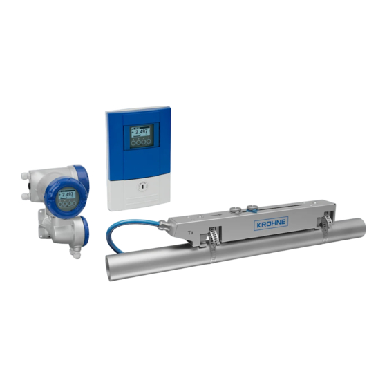
OPTISONIC 6300
OPTISONIC 6300
OPTISONIC 6300
OPTISONIC 6300
Ultrasonic clamp-on flowmeter
ER 3.4.0_
© KROHNE 07/2009 — 4000263902 — HB OPTISONIC 6300 R03 en
Handbook
Handbook
Handbook
Handbook
Related Manuals for KROHNE OPTISONIC 6300
Summary of Contents for KROHNE OPTISONIC 6300
-
Page 1
OPTISONIC 6300 OPTISONIC 6300 OPTISONIC 6300 OPTISONIC 6300 Handbook Handbook Handbook Handbook Ultrasonic clamp-on flowmeter ER 3.4.0_ © KROHNE 07/2009 — 4000263902 — HB OPTISONIC 6300 R03 en… -
Page 2
KROHNE Messtechnik GmbH & Co. KG. Subject to change without notice. Copyright 2009 by KROHNE Messtechnik GmbH & Co. KG — Ludwig-Krohne-Straße 5 — 47058 Duisburg www.krohne.com 07/2009 — 4000263902 — HB OPTISONIC 6300 R03 en… -
Page 3: Table Of Contents
3.7 Mounting of converter ………………..27 3.7.1 Mounting of UFC 300 F………………….27 3.7.2 Turning the display of the field housing version …………..27 3.7.3 Mounting of UFC 300 W………………….28 4 Electrical connections 07/2009 — 4000263902 — HB OPTISONIC 6300 R03 en www.krohne.com…
-
Page 4
7.4.1 Field version……………………103 7.4.2 Wall version……………………. 103 7.5 Spare parts availability………………..104 7.6 Availability of services ………………..104 7.7 Returning the device to the manufacturer…………..104 7.7.1 General information………………….104 www.krohne.com 07/2009 — 4000263902 — HB OPTISONIC 6300 R03 en… -
Page 5
8.3 Dimensions and weights ………………..115 8.3.1 Housing ……………………..115 8.3.2 Clamp-on sensor and cable box ………………116 8.3.3 Mounting plate, field housing ………………… 118 8.3.4 Mounting plate, wall-mounted housing …………….118 9 Notes 07/2009 — 4000263902 — HB OPTISONIC 6300 R03 en www.krohne.com… -
Page 6: Safety Instructions
• EMC Directive 89 / 336 / EEC and 93 / 68 / EEC in conjunction with EN 61326-1 (1997) and A1 (1998), A2 (2001) • Low-Voltage Directives 73 / 23 / EEC and 93 / 68 / EEC in conjunction with EN 61010-1 (2001) www.krohne.com 07/2009 — 4000263902 — HB OPTISONIC 6300 R03 en…
-
Page 7
All devices are based on the CE marking and meet the requirements of NAMUR Guideline NE 21 / 04. DANGER! For devices used in hazardous areas, additional safety notes apply; please refer to the Ex documentation. 07/2009 — 4000263902 — HB OPTISONIC 6300 R03 en www.krohne.com… -
Page 8: Safety Instructions From The Manufacturer
The manufacturer reserves the right to alter the content of its documents, including this disclaimer in any way, at any time, for any reason, without prior notification, and will not be liable in any way for possible consequences of such changes. www.krohne.com 07/2009 — 4000263902 — HB OPTISONIC 6300 R03 en…
-
Page 9: Product Liability And Warranty
This document is provided to help you establish operating conditions, which will permit safe and efficient use of this device. Special considerations and precautions are also described in the document, which appear in the form of underneath icons. 07/2009 — 4000263902 — HB OPTISONIC 6300 R03 en www.krohne.com…
-
Page 10: Warnings And Symbols Used
In general, devices from the manufacturer may only be installed, commissioned, operated and maintained by properly trained and authorized personnel. This document is provided to help you establish operating conditions, which will permit safe and efficient use of this device. www.krohne.com 07/2009 — 4000263902 — HB OPTISONIC 6300 R03 en…
-
Page 11: Device Description
® 7 Mineral coupling grease (standard versions) or high temperature contactgel Pyrogel (XT versions) 8 Signal cable plus connector cap (XT versions have a protection sleeve around the signal cable). 07/2009 — 4000263902 — HB OPTISONIC 6300 R03 en www.krohne.com…
-
Page 12: Device Description
The ultrasonic clamp-on flowmeter can be fitted on the outside of piping to measure the flow rate of liquids. The device is a combination of one up to two clamp-on sensor(s) and one ultrasonic flow converter. Figure 2-2: System configuration possibilities www.krohne.com 07/2009 — 4000263902 — HB OPTISONIC 6300 R03 en…
-
Page 13: Nameplates
2 Protection category 3 Calibration number 4 Process temperature (-40…+200°C for XT version) 5 Manufacturing year 6 Serial number 7 Device type (yyy = small, medium or large) 8 Manufacturer 07/2009 — 4000263902 — HB OPTISONIC 6300 R03 en www.krohne.com…
-
Page 14: Signal Converter
1 Manufacturer 2 Device type 3 Manufacturing year 4 Serial number sensor 1 + short code flow sensor 5 Serial number sensor 2 + short code flow sensor 6 Empty www.krohne.com 07/2009 — 4000263902 — HB OPTISONIC 6300 R03 en…
-
Page 15: Electrical Connection Data Of Inputs/Outputs (Example Of Basic Version)
• A = active mode; the signal converter supplies the power for connection of the subsequent devices • P = passive mode; external power supply required for operation of the subsequent devices • N/C = connection terminals not connected 07/2009 — 4000263902 — HB OPTISONIC 6300 R03 en www.krohne.com…
-
Page 16: Installation
• Suitable for indoor and outdoor use and certified for operating up to an altitude of 2000 m / 6562 ft • IP class 66/67 CAUTION! The device should be protected from corrosive chemicals or gases and dust / particles accumulation. www.krohne.com 07/2009 — 4000263902 — HB OPTISONIC 6300 R03 en…
-
Page 17: Installation Requirements Signal Converter
Additionally flow profile distortion is possible. CAUTION! If you program the diameter, please note that you use the outer diameter of the pipe. 07/2009 — 4000263902 — HB OPTISONIC 6300 R03 en www.krohne.com…
-
Page 18: Inlet, Outlet And Recommended Mounting Area
• If not possible, ensure adequate velocity to prevent air, gas or vapor from collecting in upper part. • In partially filled pipes, the clamp-on flowmeter will report incorrect flow rates, or not measure. Figure 3-2: Long horizontal pipes www.krohne.com 07/2009 — 4000263902 — HB OPTISONIC 6300 R03 en…
-
Page 19: Open Feed Or Discharge
Figure 3-4: Down going pipeline over 5 m /16 ft length 3.5.5 Position of control valve Always install control valves downstream of flowmeter in order to avoid cavitation or distortion of flow profile. Figure 3-5: Position of control valve 07/2009 — 4000263902 — HB OPTISONIC 6300 R03 en www.krohne.com…
-
Page 20: Position Of Pump
3.5.7 Pipe diameters and sensor construction Figure 3-7: Measuring modes 1 Z-mode 2 V-mode 3 W-mode 3.5.8 Pipe and media parameters INFORMATION! Detailed databases of most pipe and media parameters are on the supplied CD. www.krohne.com 07/2009 — 4000263902 — HB OPTISONIC 6300 R03 en…
-
Page 21: Installation Of The Flowmeter
Installation of the rails with the metal straps Installation of the rails with the metal straps Installation of the rails with the metal straps • 8: Repeat steps 1…7 at the other side of the rail. 07/2009 — 4000263902 — HB OPTISONIC 6300 R03 en www.krohne.com…
-
Page 22
• Slide the transducer 2 to the advised mounting distance 3 (menu X9.4). • Lock the transducer by turning the locking knob 1 clockwise. Greasing the transducer surfaces Greasing the transducer surfaces Greasing the transducer surfaces Greasing the transducer surfaces www.krohne.com 07/2009 — 4000263902 — HB OPTISONIC 6300 R03 en… -
Page 23: Installation Instructions For Small And Medium Version
Figure 3-8: Procedure for installation of small or medium version 1 Rail, small version 2 Rail, medium version 3 Choose for V-mode or … 4 Choose for W-mode 5 Make settings in converter 07/2009 — 4000263902 — HB OPTISONIC 6300 R03 en www.krohne.com…
-
Page 24
3 Small version: single pipe / dual path 4 Medium version: single pipe / dual path 5 Small version: dual pipe / single path 6 Medium version: dual pipe / single path www.krohne.com 07/2009 — 4000263902 — HB OPTISONIC 6300 R03 en… -
Page 25: Installation Instructions For Large Version
1 Enter the values for the installation menu, X1…X9.8.4 2 Read the advised mounting distance in menu X9.8.5 3 Choose for Z-mode (default) or … 4 Choose for V-mode 5 Finish the installation menu 07/2009 — 4000263902 — HB OPTISONIC 6300 R03 en www.krohne.com…
-
Page 26
INSTALLATION OPTISONIC 6300 Figure 3-11: Device versions 1 Single pipe, single path 2 Single pipe, dual path 3 Dual pipe www.krohne.com 07/2009 — 4000263902 — HB OPTISONIC 6300 R03 en… -
Page 27: Mounting Of Converter
Each time a housing cover is opened, the thread should be cleaned and greased. Use only resin- free and acid-free grease. Ensure that the housing gasket is properly fitted, clean and undamaged. 07/2009 — 4000263902 — HB OPTISONIC 6300 R03 en www.krohne.com…
-
Page 28: Mounting Of Ufc 300 W
• Position lock washers and nuts on the housing bolts, tighten nuts slightly. • Align housing, tighten nuts firmly. • Observe max. allowed length of 30 m / 98.4 ft for the signal cable. www.krohne.com 07/2009 — 4000263902 — HB OPTISONIC 6300 R03 en…
-
Page 29: Electrical Connections
2 Cover, terminal compartment for power supply and inputs/outputs 3 Cable entry for power 4 Cable entry for inputs/outputs 5 Cable entry for sensor cable 6 Cover, sensor terminal compartment 07/2009 — 4000263902 — HB OPTISONIC 6300 R03 en www.krohne.com…
-
Page 30: Ufc 300 W
2 Cover for the three separate terminal compartments for power, sensor connection and inputs/outputs 3 Locking screw, 1/2 turn left/right to open/close cover 2 4 Sensor terminal compartment 5 Terminal compartment for inputs/outputs 6 Power terminal compartment, open separate shock-hazard protection cover www.krohne.com 07/2009 — 4000263902 — HB OPTISONIC 6300 R03 en…
-
Page 31: Electrical Connection
1 Put in the connector. 2 Turn knob to secure the connector. CAUTION! For XT versions: check if the signal cable is heat protected with the protection sleeve of 1 meter / 40″. 07/2009 — 4000263902 — HB OPTISONIC 6300 R03 en www.krohne.com…
-
Page 32
1 Connect the blue cable to the UP rail. 2 Connect the green cable to the DOWN rail. 3 Make connections in cable box. 4 Cable to converter 5 Turn the screws clockwise to secure the caps. www.krohne.com 07/2009 — 4000263902 — HB OPTISONIC 6300 R03 en… -
Page 33: Signal Cable And Power Supply Signal Converter
1 Connect blue cable to 1U (to 2U for 2 sensor) and the green cable to 1D (2D for 2 sensor) 2 Communication I/O 3 Power supply: 24 VAC/DC or 100…240 VAC 07/2009 — 4000263902 — HB OPTISONIC 6300 R03 en www.krohne.com…
-
Page 34
U-clamp terminal in the terminal compartment of the signal converter. • When connecting to functional extra-low voltages, provide a facility for protective separation (PELV) (VDE 0100 / VDE 0106 and/or IEC 364 / IEC 536 or relevant national regulations). www.krohne.com 07/2009 — 4000263902 — HB OPTISONIC 6300 R03 en… -
Page 35: Laying Electrical Cables Correctly
2 Tighten the screw connection of the cable entry securely. 3 Never mount the housing with the cable entries facing upwards. 4 Seal cable entries that are not needed with a plug. 07/2009 — 4000263902 — HB OPTISONIC 6300 R03 en www.krohne.com…
-
Page 36: Description Of The Electrical Symbols
Electronic or electromagnetic counter At frequencies above 100 Hz, shielded cables must be used to connect the counters. Internal resistance of the counter Button, NO contact or similar Table 4-1: Description of symbols www.krohne.com 07/2009 — 4000263902 — HB OPTISONIC 6300 R03 en…
-
Page 37: Basic Inputs And Outputs
• 1 status output, • 1 control input. The pulse output can also be set as a status output. One of the status outputs can be set as a control input. 07/2009 — 4000263902 — HB OPTISONIC 6300 R03 en www.krohne.com…
-
Page 38: Fixed, Non-Alterable Input/Output Versions
1 function changed by reconnection 2 changeable • The grey boxes in the tables denote unassigned or unused connection terminals. • Connection terminal A+ is only operable in the basic input/output version. www.krohne.com 07/2009 — 4000263902 — HB OPTISONIC 6300 R03 en…
-
Page 39
Signal converter monitors cable breaks and short circuits as per EN 60947-5-6. Errors indicated on LCD display. Error messages possible via status output. Active current input Passive current input No additional module installed No further module possible 07/2009 — 4000263902 — HB OPTISONIC 6300 R03 en www.krohne.com… -
Page 40: Basic Inputs/Outputs
= 24 VDC nominal int,nom ≤ 32 VDC • U • I ≤ 22 mA ≥ 1.8 • U ≤ (U • R ) / I Figure 4-12: Current output passive I www.krohne.com 07/2009 — 4000263902 — HB OPTISONIC 6300 R03 en…
-
Page 41
) / I L, min • Can also be set as a status output; for the electrical connection, see status output connection diagram. Figure 4-13: Pulse frequency output passive P 07/2009 — 4000263902 — HB OPTISONIC 6300 R03 en www.krohne.com… -
Page 42
Contact closed (on): U = 2.8 mA • Can also be set as a status output; for the electrical connection, see status output connection diagram. Figure 4-15: Control input passive C 1 Signal www.krohne.com 07/2009 — 4000263902 — HB OPTISONIC 6300 R03 en… -
Page 43: Hart ® Connection
1 Basic I/O: terminals A and A+ 2 Modular I/O: terminals C- and C ® 3 HART communicator communicator must be R ≥ 230 Ω. ® The parallel resistance to the HART 07/2009 — 4000263902 — HB OPTISONIC 6300 R03 en www.krohne.com…
-
Page 44: Modular Inputs And Outputs
2 option modules for term. A + B passive ® + HART passive 7 _ _ max. 2 option modules for term. A + B NAMUR ® + HART active www.krohne.com 07/2009 — 4000263902 — HB OPTISONIC 6300 R03 en…
-
Page 45
Signal converter monitors cable breaks and short circuits as per EN 60947-5-6. Errors indicated on LCD display. Error messages possible via status output. Active current input Passive current input No additional module installed No further module possible 07/2009 — 4000263902 — HB OPTISONIC 6300 R03 en www.krohne.com… -
Page 46: Modular Inputs/Outputs And Bus Systems
≤ (U • R ) / I • X designates the connection terminals A, B or C, depending on the version of the signal converter. Figure 4-19: Current output passive I www.krohne.com 07/2009 — 4000263902 — HB OPTISONIC 6300 R03 en…
-
Page 47
) / I L, min • X designates the connection terminals A, B or D, depending on the version of the signal converter. Figure 4-20: Pulse / frequency output active P 07/2009 — 4000263902 — HB OPTISONIC 6300 R03 en www.krohne.com… -
Page 48
• Can also be set as a status output; see status output connection diagram. • X designates the connection terminals A, B or D, depending on the version of the signal converter. Figure 4-21: Pulse frequency output passive P www.krohne.com 07/2009 — 4000263902 — HB OPTISONIC 6300 R03 en… -
Page 49
• X designates the connection terminals A, B or D, depending on the version of the signal converter. Figure 4-22: Pulse and frequency output passive P to NAMUR EN 60947-5-6 07/2009 — 4000263902 — HB OPTISONIC 6300 R03 en www.krohne.com… -
Page 50
• The output is open when the device is de-energized. • X designates the connection terminals A, B or D, depending on the version of the signal converter. Figure 4-24: Status output / limit switch passive S www.krohne.com 07/2009 — 4000263902 — HB OPTISONIC 6300 R03 en… -
Page 51
• X designates the connection terminals A, B or D, depending on the version of the signal converter. Figure 4-25: Status output / limit switch S to NAMUR EN 60947-5-6 07/2009 — 4000263902 — HB OPTISONIC 6300 R03 en www.krohne.com… -
Page 52
Contact closed (on): U = 1.9 mA • X designates the connection terminals A or B, depending on the version of the signal converter. Figure 4-27: Control input passive C 1 Signal www.krohne.com 07/2009 — 4000263902 — HB OPTISONIC 6300 R03 en… -
Page 53
≤ 1.2 V with I ≥ 6.7 mA • X designates the connection terminals A or B, depending on the version of the signal converter. Figure 4-28: Control input active C to NAMUR EN 60947-5-6 07/2009 — 4000263902 — HB OPTISONIC 6300 R03 en www.krohne.com… -
Page 54: Hart ® Connection
1 Basic I/O: terminals A and A+ 2 Modular I/O: terminals C- and C ® 3 HART communicator communicator must be R ≥ 230 Ω. ® The parallel resistance to the HART www.krohne.com 07/2009 — 4000263902 — HB OPTISONIC 6300 R03 en…
-
Page 55
Figure 4-30: HART connection passive (I 1 Basic I/O: terminals A- and A 2 Modular I/O: terminals C- and C ® 3 HART communicator ® 4 Other HART — capable devices 07/2009 — 4000263902 — HB OPTISONIC 6300 R03 en www.krohne.com… -
Page 56: Start-Up
Esc (> + ↑) Return to menu mode Return to sub-menu or without acceptance of function without data acceptance of data Table 5-1: Description of key functionality www.krohne.com 07/2009 — 4000263902 — HB OPTISONIC 6300 R03 en…
-
Page 57
Start installation menu • Connect converter to power supply and power up converter. First and second page appear intermittently • Keep left button «>» pressed, until in display appears «release key now». 07/2009 — 4000263902 — HB OPTISONIC 6300 R03 en www.krohne.com… -
Page 58
> ↓ > fill in using ↑ ↓ > X6.13 viscosity > ↑ ↓ pipe data 2 > ↑ ↓ X7.1 copy pipe 1 data > start to copy ? www.krohne.com 07/2009 — 4000263902 — HB OPTISONIC 6300 R03 en… -
Page 59
(underneath X10 becomes active if two pipes or two paths (underneath X10 becomes active if two pipes or two paths are selected in X4 or X5) ↑ ↓ install transd. 2 > submenus identical to X9.1 up to X9.12 07/2009 — 4000263902 — HB OPTISONIC 6300 R03 en www.krohne.com… -
Page 60: Start Measurement Of Small / Medium Version
• X9.12: End Installation? Enter «Yes» to save the installation. The measurement screen will appear. • Mount the cover (see the section «mounting the cover» in chapter «General mechanical installation») www.krohne.com 07/2009 — 4000263902 — HB OPTISONIC 6300 R03 en…
-
Page 61: Start Measurement Of Large Version
• X9.7: Press enter • X9.8: Optimization loop. Enter «No» in X9.8.1 • X9.9: Press enter. Wait for 30 seconds • X9.10: Path ready? Enter «Yes» • X9.12: End Installation? Enter «Yes» 07/2009 — 4000263902 — HB OPTISONIC 6300 R03 en www.krohne.com…
-
Page 62
Advised distance [mm] Advised distance [mm] Transducer position [mm] Transducer position [mm] 100…250 >250 Figure 5-3: Device versions 1 Single pipe, single path 2 Single pipe, dual path 3 Dual pipe www.krohne.com 07/2009 — 4000263902 — HB OPTISONIC 6300 R03 en… -
Page 63: Mechanical Installation For Large Version
Figure 5-4: Mounting the large rail 1 Align the UP rail with the pipeline. 2 Fixing units 3 Turn screws clockwise to secure. 4 Mark the position. 5 Cable box 07/2009 — 4000263902 — HB OPTISONIC 6300 R03 en www.krohne.com…
-
Page 64
5 Mount the cable box (only for downstream metal strap). 6 Push the metal strap through the upper slit of the fixing unit. 7 Pull the metal strap moderately tight by hand. • Secure by turning screws clockwise. www.krohne.com 07/2009 — 4000263902 — HB OPTISONIC 6300 R03 en… -
Page 65
2 Add the Advised Distance and mark the location on the alignment line. • Mount the DOWN rail in such a way that the transducer is at the marked location. 2. FIND THE LOCATION WITH THE SUPPLIED POSITIONING TOOL 07/2009 — 4000263902 — HB OPTISONIC 6300 R03 en www.krohne.com… -
Page 66
2 Outer diameter of pipeline INFORMATION! For large diameters you can use the weight of the metal plates to throw the cable around the pipe. First release one of the cables in that case! www.krohne.com 07/2009 — 4000263902 — HB OPTISONIC 6300 R03 en… -
Page 67
Repeat above steps to check if you find the same points. Figure 5-8: Marking the opposite location Calculate the middle of the alignment line between the 4 V-marks as shown. 07/2009 — 4000263902 — HB OPTISONIC 6300 R03 en www.krohne.com… -
Page 68
• Mount the DOWN rail in such a way that the transducer is at the marked location. • Grease all transducers, see «General mechanical installation». INFORMATION! It can be necessary to install the DOWN rail as shown below. www.krohne.com 07/2009 — 4000263902 — HB OPTISONIC 6300 R03 en… -
Page 69
Figure 5-10: Mounting large version in V-mode 1 Fixing units 2 Reference marking 3 Cable box 4 Advised Distance, X9.4 5 Minimum distance between UP and DOWN rail: 110 mm / 4.3″ 07/2009 — 4000263902 — HB OPTISONIC 6300 R03 en www.krohne.com… -
Page 70
1 Connect blue cable to 1U (to 2U for 2 sensor) and the green cable to 1D (2D for 2 sensor) 2 Communication I/O 3 Power supply: 24 VAC/DC or 100…240 VAC www.krohne.com 07/2009 — 4000263902 — HB OPTISONIC 6300 R03 en… -
Page 71
Signal < 10%: Signal < 10%: Signal < 10%: Signal < 10%: bad or no signal, check settings in menu X6, increase transducer distance and/or go into the optimization loop. 07/2009 — 4000263902 — HB OPTISONIC 6300 R03 en www.krohne.com… -
Page 72
• X9.12: End Installation? If you enter «No» the installation is not saved, go to X9. If you enter «Yes» the installation is saved and the measurement screen will appear. • Mount the cover (see section «mounting the cover» in chapter «General mechanical installation») www.krohne.com 07/2009 — 4000263902 — HB OPTISONIC 6300 R03 en… -
Page 73: Operation
IO Counter IO HART device INFORMATION! You find the description of the X Installation X Installation X Installation menu in Chapter 5 of this handbook X Installation 07/2009 — 4000263902 — HB OPTISONIC 6300 R03 en www.krohne.com…
-
Page 74: Menu Structure
HART current output is selected if yes: all analog outputs are selected ↑ ↓ digital outputs > A5.1, A5.2,… A5.1 measurement > select from list using ↑ ↓ > www.krohne.com 07/2009 — 4000263902 — HB OPTISONIC 6300 R03 en…
-
Page 75
> ↑ ↓ use at all outputs yes/no if no: only pulse output D is selected if yes: all digital outputs are selected ↑ ↓ GDC IR interface > activate/cancel 07/2009 — 4000263902 — HB OPTISONIC 6300 R03 en www.krohne.com… -
Page 76: Test
(additional menus for two pipes) ↑ ↓ B.2.3 act. Reynolds nr. > (additional menus for two pipes) ↑ ↓ B.2.4 act. vel. of sound > (additional menus for two pipes) www.krohne.com 07/2009 — 4000263902 — HB OPTISONIC 6300 R03 en…
-
Page 77
C number read ↑ ↓ B3.2 process input B3.2.1 sensor CPU read B3.2.2 sensor DSP read B3.2.3 sensor driver read ↑ ↓ B3.3 device sernr/swnr/yymm ↑ ↓ B3.4 display sernr/swnr/yymm 07/2009 — 4000263902 — HB OPTISONIC 6300 R03 en www.krohne.com… -
Page 78: Setup
C1.10.1, C1.10.2,… C1.10.1 sensor CPU read C1.10.2 sensor DSP read C1.10.3 sensor driver read fill in using ↑ ↓ > C1.11 diagnosis value > ↑ ↓ process input 2 > www.krohne.com 07/2009 — 4000263902 — HB OPTISONIC 6300 R03 en…
-
Page 79
> ↑ ↓ C1.10 information > C1.10.1, C1.10.2,… C1.10.1 sensor CPU read C1.10.2 sensor DSP read C1.10.3 sensor driver read fill in using ↑ ↓ > C1.11 diagnosis value > 07/2009 — 4000263902 — HB OPTISONIC 6300 R03 en www.krohne.com… -
Page 80
↑ ↓ > C5.3.3 100 % pulse rate > C5.3.4 measurement > select from list using ↑ ↓ fill in using ↑ ↓ > C5.3.5 range > www.krohne.com 07/2009 — 4000263902 — HB OPTISONIC 6300 R03 en… -
Page 81
Y > read: status off C5.5.7 control input Y > read: status off C5.5.8 > read: status off C5.5.9 invert signal > select on/off C5.5.10 information > read 07/2009 — 4000263902 — HB OPTISONIC 6300 R03 en www.krohne.com… -
Page 82
> read C7.1.3 HART dynamic > select from list using ↑ ↓ variable C7.2 SV is > C7.2.1 C7.2.1 HART dynamic > select from list using ↑ ↓ variable www.krohne.com 07/2009 — 4000263902 — HB OPTISONIC 6300 R03 en… -
Page 83
> C8.5.1, C8.5.2,… C8.5.1 select range > select manual/automatic fill in using ↑ ↓ > C8.5.2 range > fill in using ↑ ↓ > C8.5.3 time scale > 07/2009 — 4000263902 — HB OPTISONIC 6300 R03 en www.krohne.com… -
Page 84
> ↑ ↓ C8.9 quick setup > C8.9.1, C8.9.2,… C8.9.1 reset counter 1 > select yes/no C8.9.2 reset counter 2 > select yes/no C8.9.3 reset counter 3 > select yes/no www.krohne.com 07/2009 — 4000263902 — HB OPTISONIC 6300 R03 en… -
Page 85: Customize Settings
↑ ↓ > X12.4 Tb calibration no. > fill in using ↑ ↓ > X12.5 Tc serial no. > fill in using ↑ ↓ > X12.6 Tc calibration no. > 07/2009 — 4000263902 — HB OPTISONIC 6300 R03 en www.krohne.com…
-
Page 86: Function Description
HART current output (depends on pipe configuration: 1 or 2 pipes) volume flow, mass flow, VoS, flow speed, gain, SNR, diagnosis value, volume flow 1 or 2, VoS 1 or 2 www.krohne.com 07/2009 — 4000263902 — HB OPTISONIC 6300 R03 en…
-
Page 87
0.500 — 2.000 volume flow, mass flow, flow speed and Reynolds number C1.6.3 Reynolds set Reynolds correction for flow on,off correction profile disturbances, effective on volume flow, mass flow 07/2009 — 4000263902 — HB OPTISONIC 6300 R03 en www.krohne.com… -
Page 88
C5.2.10 time constant within set time, measurements min-max: 000.1 — 100.0 are averaged, displayed and sent to current output C5.2.11 special functions for ranging automatic range, external range, off www.krohne.com 07/2009 — 4000263902 — HB OPTISONIC 6300 R03 en… -
Page 89
00.0 — 20.0 C5.4.9 time constant within set time, measurements min-max: 000.1 — 100.0 are averaged, displayed and sent to current output C5.4.10 invert signal activate switch closed, open off, on 07/2009 — 4000263902 — HB OPTISONIC 6300 R03 en www.krohne.com… -
Page 90
C5.6.6 information serial number of circuit board, software version, calibration date of circuit board www.krohne.com 07/2009 — 4000263902 — HB OPTISONIC 6300 R03 en… -
Page 91
C7.3 TV is Third Variable C7.4 4V is Fourth Variable device device device device C8.2.2 contrast min-max: -9 — +9 C8.2.3 default display 1.meas.page, 2.meas.page, graphic page, status page, none 07/2009 — 4000263902 — HB OPTISONIC 6300 R03 en www.krohne.com… -
Page 92
ST, LT, free unit C8.7.7 density kg/L, kg/m3, lb/ft3, lb/gal, free unit C8.7.8 viscosity cSt, m2/s, mm2/s C8.8.1 HART factory setting: HART communication on; generates F: application error open circuit A www.krohne.com 07/2009 — 4000263902 — HB OPTISONIC 6300 R03 en… -
Page 93: Error Messages
A current on current output A (or B, extend upper or lower limit for (or B, C) C) is limited by parameter setting current output in menu C5.2.8 07/2009 — 4000263902 — HB OPTISONIC 6300 R03 en www.krohne.com…
-
Page 94
DSP and error microprocessor software www.krohne.com 07/2009 — 4000263902 — HB OPTISONIC 6300 R03 en… -
Page 95: Service
Clean pipe and contact surfaces of transducers with a soft cloth. • Regrease the contact surfaces of transducers 4. • Turn rail 90 degrees back 5. • Press rail at both ends to the pipe by clicking 6. 07/2009 — 4000263902 — HB OPTISONIC 6300 R03 en www.krohne.com…
-
Page 96: Cleaning
Only the sensor calibration data are loaded. — if in the screen appears “load no data load no data load no data”, all data have been lost. Contact your local load no data representative. www.krohne.com 07/2009 — 4000263902 — HB OPTISONIC 6300 R03 en…
-
Page 97: Field Version
CAUTION! Please pay attention that the same amount of force is applied on both pullers, otherwise the connector at the backside can be damaged. 07/2009 — 4000263902 — HB OPTISONIC 6300 R03 en www.krohne.com…
-
Page 98
• Screw the electronics unit back to the housing. • Re-install the display and make sure not to kink the display’s flat ribbon cable. • Replace cover and tighten by hand. • Connect power. www.krohne.com 07/2009 — 4000263902 — HB OPTISONIC 6300 R03 en… -
Page 99: Wall Version
• Turn locking screw to the left 1 to unlock the lower door. • Open lower door. • Slide metal slider, positioned at the left upper angle, downwards. • Open upper door 2. 07/2009 — 4000263902 — HB OPTISONIC 6300 R03 en www.krohne.com…
-
Page 100
• Unscrew the two M4 screws 7 at the electronics unit 5. Figure 7-7: Release printed circuit board • Remove the small printed circuit board 6with care. • Carefully slide the electronics unit 5, then lift it out of the housing. www.krohne.com 07/2009 — 4000263902 — HB OPTISONIC 6300 R03 en… -
Page 101
• Close and lock the lower door. • Connect power. CAUTION! First program the installation menu, refer to General instructions for programming on page 56 and check all important settings. 07/2009 — 4000263902 — HB OPTISONIC 6300 R03 en www.krohne.com… -
Page 102: Replacing The Mains Fuse
0.8AT/H/250 , breaking capacity 1500 A at 250 V • 24 VAC/DC power supply: 24 VAC/DC power supply: 24 VAC/DC power supply: 24 VAC/DC power supply: 2AT/H/250 , breaking capacity 1500 A at 250 V www.krohne.com 07/2009 — 4000263902 — HB OPTISONIC 6300 R03 en…
-
Page 103: Field Version
• Mount the small printed circuit board back onto the sensor driver board. • Put the electronics unit back to the housing. • Click the display back into the holders. • Close the housing and lock the doors. • Connect power. 07/2009 — 4000263902 — HB OPTISONIC 6300 R03 en www.krohne.com…
-
Page 104: Spare Parts Availability
• such dangerous substances, to enclose a certificate with the device confirming that is safe to handle and stating the • product used. www.krohne.com 07/2009 — 4000263902 — HB OPTISONIC 6300 R03 en…
-
Page 105: Form (For Copying) To Accompany A Returned Device
We hereby confirm that there is no risk to persons or the environment through any residual media contained in the device when it is returned. Date: Signature: Stamp: 7.8 Disposal CAUTION! Disposal must be carried out in accordance with legislation applicable in your country. 07/2009 — 4000263902 — HB OPTISONIC 6300 R03 en www.krohne.com…
-
Page 106: Technical Data
• The difference in transit time is directly proportional to the mean flow velocity of the medium. Figure 8-1: Measuring principle 1 Transducer A 2 Transducer B 3 Flow velocity 4 Transit time from transducer A to B 5 Transit time from transducer B to A www.krohne.com 07/2009 — 4000263902 — HB OPTISONIC 6300 R03 en…
-
Page 107: Technical Data
2 internal counters with a max. of 8 counter places (e.g. for counting volume and/or mass units) Self diagnostics Integrated verification, diagnosis functions: flowmeter, process, measured value, empty pipe detection, bargraph 07/2009 — 4000263902 — HB OPTISONIC 6300 R03 en www.krohne.com…
-
Page 108
Metal, plastic, ceramic, asbestos cement, internal / external coated pipes (coatings and liners fully bonded to pipe wall) Pipewall thickness < 200 mm / 7.87″ Liner thickness < 20 mm / 0.79″ www.krohne.com 07/2009 — 4000263902 — HB OPTISONIC 6300 R03 en… -
Page 109
2 internal triax, available lengths: 5 m / 15 ft (standard), maximum length 30 m / 90 ft Cable entries Standard: M20 x 1.5 Option: ½» NPT, PF ½ 07/2009 — 4000263902 — HB OPTISONIC 6300 R03 en www.krohne.com… -
Page 110
≥ 250 Ω Load Please observe maximum value for current output Multidrop Yes, current output = 4 mA Multidrop addresses programmable in menu 1…15 Device drivers FDT/DTM www.krohne.com 07/2009 — 4000263902 — HB OPTISONIC 6300 R03 en… -
Page 111
= 0.6 mA open: I = 0.43 mA closed: I = 3.8 mA closed: I = 4.5 mA = 30 V = 100 mA = 1 W =10 nF ~ 0 mH 07/2009 — 4000263902 — HB OPTISONIC 6300 R03 en www.krohne.com… -
Page 112
= 0.6 mA open: I = 0.43 mA closed: I = 3.8 mA closed: I = 4.5 mA = 30 V = 100 mA = 1 W =10 nF = 0 mH www.krohne.com 07/2009 — 4000263902 — HB OPTISONIC 6300 R03 en… -
Page 113
Can be set together for all flow indicators and outputs, or separately for: current, pulse and frequency output, and for limit switches and the 3 internal counters Time setting 0…100 seconds, settable in 0.1 second steps 07/2009 — 4000263902 — HB OPTISONIC 6300 R03 en www.krohne.com… -
Page 114
Other approvals and standards Other approvals and standards Other approvals and standards Electromagnetic compatibility Directive: 89/336/EEC, NAMUR NE21/04 Harmonized standard: EN 61326-1: 2006 Low Voltage Directive Directive: 2006/95/EC Harmonized standard: EN 61010: 2001 www.krohne.com 07/2009 — 4000263902 — HB OPTISONIC 6300 R03 en… -
Page 115: Dimensions And Weights
Dimensions and weights in mm and kg Version Dimensions [mm] Weights [kg] 295.8 Dimensions and weights in inches and lbs Version Dimensions [inches] Weights [lbs] 7.75 4.75 6.10 11.60 10.90 12.60 7.80 5.40 11.80 5.30 07/2009 — 4000263902 — HB OPTISONIC 6300 R03 en www.krohne.com…
-
Page 116: Clamp-On Sensor And Cable Box
32.5 Large 19.5 Small — stainless 19.4 steel / XT Medium — stainless 32.4 steel / XT 1 value for one of the 2 delivered rails 2 delivered without cover www.krohne.com 07/2009 — 4000263902 — HB OPTISONIC 6300 R03 en…
-
Page 117
TECHNICAL DATA OPTISONIC 6300 Dimensions [mm] Approx. weight without cable/metal [kg] Cable box 0.85 Dimensions [inches] Approx. weight without cable/metal [lbs] Cable box 4.01 7.76 2.64 1.87 07/2009 — 4000263902 — HB OPTISONIC 6300 R03 en www.krohne.com… -
Page 118: Mounting Plate, Field Housing
OPTISONIC 6300 8.3.3 Mounting plate, field housing Dimensions in mm and inches [mm] [inches] Ø9 Ø0.4 8.3.4 Mounting plate, wall-mounted housing Dimensions in mm and inches [mm] [inches] Ø9 Ø0.4 3.85 www.krohne.com 07/2009 — 4000263902 — HB OPTISONIC 6300 R03 en…
-
Page 119
NOTES OPTISONIC 6300 07/2009 — 4000263902 — HB OPTISONIC 6300 R03 en www.krohne.com… -
Page 120
Measuring systems for sea-going tankers Head Office KROHNE Messtechnik GmbH & Co. KG Ludwig-Krohne-Str. 5 D-47058 Duisburg (Germany) Tel.:+49 (0)203 301 0 Fax:+49 (0)203 301 10389 info@krohne.de The current list of all KROHNE contacts and addresses can be found at: www.krohne.com…

Ультразвуковой накладной расходометр
ER 3.4.0_
OPTISONIC 6300
Руководство по эксплуатации
© KROHNE 10/2011 — 4001688601 — MA OPTISONIC 6300 R01 ru


 OPTISONIC 6300 P Handbook
Portable ultrasonic clamp-on flowmeter
Electronic Revision: ER 1.1.2_
(SW.REV 01.01.01_)
© KROHNE 03/2013 — 4000972603 — MA OPTISONIC 6300 P R03 en
:IMPRINT :::::::::::::::::::::::::::::::::::::::
All rights reserved. It is prohibited to reproduce this documentation, or any part thereof, without the prior written authorisation of KROHNE Messtechnik GmbH.
Subject to change without notice.
Copyright 2013 by
KROHNE Messtechnik GmbH — Ludwig-Krohne-Str. 5 — 47058 Duisburg (Germany)
|
2 |
www.krohne.com |
03/2013 — 4000972603 — MA OPTISONIC 6300 P R03 en |

|
OPTISONIC 6300 P |
CONTENTS |
|
|
1 Safety instructions |
5 |
|
|
1.1 |
Intended use ……………………………………………………………………………………………………… |
5 |
|
1.2 |
Certification ………………………………………………………………………………………………………. |
5 |
|
1.3 |
Safety instructions from the manufacturer …………………………………………………………… |
6 |
|
1.3.1 Copyright and data protection …………………………………………………………………………………… |
6 |
|
|
1.3.2 Disclaimer ………………………………………………………………………………………………………………. |
6 |
|
|
1.3.3 Product liability and warranty …………………………………………………………………………………… |
7 |
|
|
1.3.4 Information concerning the documentation………………………………………………………………… |
7 |
|
|
1.3.5 Warnings and symbols used……………………………………………………………………………………… |
8 |
|
|
2 Device description |
9 |
|
|
2.1 |
Scope of delivery………………………………………………………………………………………………… |
9 |
|
2.2 |
Nameplates …………………………………………………………………………………………………….. |
10 |
|
3 Installation for flow measurement |
12 |
|
|
3.1 |
General safety instructions ……………………………………………………………………………….. |
12 |
|
3.2 |
Step 1: Find location and determine data ……………………………………………………………. |
13 |
|
3.3 |
Step 2: Initialise the UFC 300 P converter …………………………………………………………… |
17 |
|
3.4 |
Step 3: Mount the sensor rails …………………………………………………………………………… |
23 |
|
3.4.1 2 or 4 traverses with 1 rail ……………………………………………………………………………………… |
26 |
|
|
3.4.2 2 traverses with 2 rails …………………………………………………………………………………………… |
27 |
|
|
3.4.3 1 traverse with 2 rails (DN400…1500) ………………………………………………………………………. |
28 |
|
|
3.4.4 Apply coupling grease…………………………………………………………………………………………….. |
29 |
|
|
3.4.5 Connect the sensor cable ……………………………………………………………………………………….. |
30 |
|
|
3.5 |
Step 4: Optimization loop ………………………………………………………………………………….. |
31 |
|
3.6 |
Step 5: start flow measurement ………………………………………………………………………… |
32 |
|
3.7 |
Error messages……………………………………………………………………………………………….. |
33 |
|
4 Installation for energy measurement |
35 |
|
|
4.1 |
Preparation of energy measurement………………………………………………………………….. |
35 |
|
4.2 |
Mechanical installation …………………………………………………………………………………….. |
36 |
|
4.3 |
Program the converter……………………………………………………………………………………… |
38 |
|
4.3.1 Program the I/O input …………………………………………………………………………………………….. |
38 |
|
|
4.3.2 Program the process input……………………………………………………………………………………… |
39 |
|
|
4.3.3 Program the counters…………………………………………………………………………………………….. |
40 |
|
|
4.4 |
Start measurement ………………………………………………………………………………………….. |
41 |
|
03/2013 — 4000972603 — MA OPTISONIC 6300 P R03 en |
www.krohne.com |
3 |

|
CONTENTS |
OPTISONIC 6300 P |
||
|
5 Electrical connections |
42 |
||
|
5.1 |
Safety instructions……………………………………………………………………………………………. |
42 |
|
|
5.2 |
Location of connectors at the converter ……………………………………………………………… |
42 |
|
|
5.3 |
Power supply …………………………………………………………………………………………………… |
43 |
|
|
5.4 |
Signal cable …………………………………………………………………………………………………….. |
43 |
|
|
5.5 |
USB connector…………………………………………………………………………………………………. |
44 |
|
|
5.6 |
I/O cable………………………………………………………………………………………………………….. |
46 |
|
|
5.7 |
Connection diagrams ……………………………………………………………………………………….. |
47 |
|
|
6 Operation |
52 |
||
|
6.1 |
Display configuration………………………………………………………………………………………… |
52 |
|
|
6.1.1 Step 1: how to set up the display for showing measured values ………………………………….. |
52 |
||
|
6.1.2 |
Basic settings of display …………………………………………………………………………………………. |
53 |
|
|
6.2 |
Programming the transducer calibration number……………………………………………….. |
54 |
|
|
6.3 |
Data logging…………………………………………………………………………………………………….. |
55 |
|
|
6.3.1 Step 1: how to set up the data logger ……………………………………………………………………….. |
55 |
||
|
6.3.2 Step 2: how to start data logging……………………………………………………………………………… |
58 |
||
|
6.3.3 Step 3: how to view logged data……………………………………………………………………………….. |
58 |
||
|
6.4 |
How to transfer data to a PC ……………………………………………………………………………… |
59 |
|
|
6.4.1 |
Site files………………………………………………………………………………………………………………… |
59 |
|
|
6.4.2 |
Log files………………………………………………………………………………………………………………… |
60 |
|
|
6.4.3 Managing your files from your pc…………………………………………………………………………….. |
61 |
||
|
6.5 |
Menu description……………………………………………………………………………………………… |
62 |
|
|
7 Service |
73 |
||
|
7.1 |
Spare parts availability……………………………………………………………………………………… |
73 |
|
|
7.2 |
Availability of services ………………………………………………………………………………………. |
73 |
|
|
7.3 |
Returning the device to the manufacturer…………………………………………………………… |
73 |
|
|
7.3.1 General information……………………………………………………………………………………………….. |
73 |
||
|
7.3.2 Form (for copying) to accompany a returned device…………………………………………………… |
74 |
||
|
7.4 |
Disposal ………………………………………………………………………………………………………….. |
74 |
|
|
8 Technical data |
75 |
||
|
8.1 |
Measuring principle………………………………………………………………………………………….. |
75 |
|
|
8.2 |
Technical data………………………………………………………………………………………………….. |
76 |
|
|
8.3 |
Dimensions and weights …………………………………………………………………………………… |
82 |
|
|
8.3.1 Clamp-on sensor …………………………………………………………………………………………………… |
82 |
||
|
8.3.2 Converter………………………………………………………………………………………………………………. |
83 |
||
|
8.3.3 I/O box ………………………………………………………………………………………………………………….. |
84 |
||
|
8.3.4 Trunk on wheels…………………………………………………………………………………………………….. |
85 |
||
|
9 Notes |
86 |
||
|
4 |
www.krohne.com |
03/2013 — 4000972603 — MA OPTISONIC 6300 P R03 en |

|
SAFETY INSTRUCTIONS 1 |
||
|
OPTISONIC 6300 P |
||
1.1 Intended use
CAUTION!
Responsibility for the use of the measuring devices with regard to suitability, intended use and corrosion resistance of the used materials against the measured fluid lies solely with the operator.
INFORMATION!
The manufacturer is not liable for any damage resulting from improper use or use for other than the intended purpose.
The OPTISONIC 6300 P portable clamp-on flow meter is designed for measurement of liquid flows in full pipes, datalogging and transfer of logged results to the PC. The portable clamp-on flow meter makes it possible to measure the flow on places temporary or you can make use of it if you want to compare the output with other measurement devices.
If an inline measurement device is broken and you are in need of the information the OPTISONIC 6300 P might be the solution for you.
1.2 Certification
In accordance with the commitment to customer service and safety, the device described in this document meets the following safety requirements:
•EMC Directive 2004/108/EC and 93/68/EEC in conjunction with EN 61326-1 (1997) and A1 (1998), A2 (2001)
•Low-Voltage Directives 73/23/EEC and 93/68/EEC in conjunction with EN 61010-1 (2001)
|
03/2013 — 4000972603 — MA OPTISONIC 6300 P R03 en |
www.krohne.com |
5 |

|
1 SAFETY INSTRUCTIONS |
||
|
OPTISONIC 6300 P |
||
1.3 Safety instructions from the manufacturer
1.3.1 Copyright and data protection
The contents of this document have been created with great care. Nevertheless, we provide no guarantee that the contents are correct, complete or up-to-date.
The contents and works in this document are subject to copyright. Contributions from third parties are identified as such. Reproduction, processing, dissemination and any type of use beyond what is permitted under copyright requires written authorisation from the respective author and/or the manufacturer.
The manufacturer tries always to observe the copyrights of others, and to draw on works created in-house or works in the public domain.
The collection of personal data (such as names, street addresses or e-mail addresses) in the manufacturer’s documents is always on a voluntary basis whenever possible. Whenever feasible, it is always possible to make use of the offerings and services without providing any personal data.
We draw your attention to the fact that data transmission over the Internet (e.g. when communicating by e-mail) may involve gaps in security. It is not possible to protect such data completely against access by third parties.
We hereby expressly prohibit the use of the contact data published as part of our duty to publish an imprint for the purpose of sending us any advertising or informational materials that we have not expressly requested.
1.3.2 Disclaimer
The manufacturer will not be liable for any damage of any kind by using its product, including, but not limited to direct, indirect or incidental and consequential damages.
This disclaimer does not apply in case the manufacturer has acted on purpose or with gross negligence. In the event any applicable law does not allow such limitations on implied warranties or the exclusion of limitation of certain damages, you may, if such law applies to you, not be subject to some or all of the above disclaimer, exclusions or limitations.
Any product purchased from the manufacturer is warranted in accordance with the relevant product documentation and our Terms and Conditions of Sale.
The manufacturer reserves the right to alter the content of its documents, including this disclaimer in any way, at any time, for any reason, without prior notification, and will not be liable in any way for possible consequences of such changes.
|
6 |
www.krohne.com |
03/2013 — 4000972603 — MA OPTISONIC 6300 P R03 en |

|
SAFETY INSTRUCTIONS 1 |
||
|
OPTISONIC 6300 P |
||
1.3.3 Product liability and warranty
The operator shall bear responsibility for the suitability of the device for the specific purpose. The manufacturer accepts no liability for the consequences of misuse by the operator. Improper installation and operation of the devices (systems) will cause the warranty to be void. The respective «Standard Terms and Conditions» which form the basis for the sales contract shall also apply.
1.3.4 Information concerning the documentation
To prevent any injury to the user or damage to the device it is essential that you read the information in this document and observe applicable national standards, safety requirements and accident prevention regulations.
If this document is not in your native language and if you have any problems understanding the text, we advise you to contact your local office for assistance. The manufacturer can not accept responsibility for any damage or injury caused by misunderstanding of the information in this document.
This document is provided to help you establish operating conditions, which will permit safe and efficient use of this device. Special considerations and precautions are also described in the document, which appear in the form of underneath icons.
|
03/2013 — 4000972603 — MA OPTISONIC 6300 P R03 en |
www.krohne.com |
7 |

|
1 SAFETY INSTRUCTIONS |
||
|
OPTISONIC 6300 P |
||
1.3.5 Warnings and symbols used
Safety warnings are indicated by the following symbols.
DANGER!
This information refers to the immediate danger when working with electricity.
DANGER!
This warning refers to the immediate danger of burns caused by heat or hot surfaces.
DANGER!
This warning refers to the immediate danger when using this device in a hazardous atmosphere.
DANGER!
These warnings must be observed without fail. Even partial disregard of this warning can lead to serious health problems and even death. There is also the risk of seriously damaging the device or parts of the operator’s plant.
WARNING!
Disregarding this safety warning, even if only in part, poses the risk of serious health problems. There is also the risk of damaging the device or parts of the operator’s plant.
CAUTION!
Disregarding these instructions can result in damage to the device or to parts of the operator’s plant.
INFORMATION!
These instructions contain important information for the handling of the device.
LEGAL NOTICE!
This note contains information on statutory directives and standards.
• HANDLING
This symbol designates all instructions for actions to be carried out by the operator in the specified sequence.
iRESULT
This symbol refers to all important consequences of the previous actions.
|
8 |
www.krohne.com |
03/2013 — 4000972603 — MA OPTISONIC 6300 P R03 en |
|
DEVICE DESCRIPTION 2 |
||
|
OPTISONIC 6300 P |
||
2.1 Scope of delivery
INFORMATION!
Do a check of the packing list to make sure that you have all the elements given in the order.
INFORMATION!
Inspect the cartons carefully for damages or signs of rough handling. Report damage to the carrier and to the local office of the manufacturer.
CAUTION!
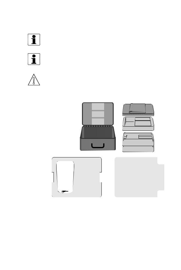
The device arrives in a plastic trunk on wheels, unless ordered otherwise.
Figure 2-1: Scope of delivery
1Product documentation, factory calibration report
2Trunk on wheels
3Carrying bag
4Tray with one or two rails
5Metal / textile straps for mounting rail(s) and converter
6Sensor(s) with fixing units (small version 1, medium version 2 sensors)
2 Transducers (small versions: 2 MHz, medium version: 1 MHz), including 3 m cable, coupling grease
7Power adapter including plugs for EU, UK, US and AUS
8USB memory stick, measure band
optionally I/O box and/or temperature sensors, PC connection cable
9UFC 300 P Signal converter
INFORMATION!
Delivered content can be different, dependent on the ordered version. A checklist is included with the product, check if all items on this checklist are delivered.
|
03/2013 — 4000972603 — MA OPTISONIC 6300 P R03 en |
www.krohne.com |
9 |

|
2 DEVICE DESCRIPTION |
OPTISONIC 6300 P |
||||||||||||||||
|
2.2 Nameplates |
|||||||||||||||||
Figure 2-2: Nameplate flow sensor
1Ambient temperature operating range
2Protection category
3Process temperature
4Manufacturing year
5Article number
6Description
7Device type
8Name and address of the manufacturer
Figure 2-3: Nameplate converter
1Name and address of the manufacturer
2Device type
3Serial number
4Manufacturing year
5Protection class and temperature data
6Treat device as electronic garbage according WEEE rules.
|
10 |
www.krohne.com |
03/2013 — 4000972603 — MA OPTISONIC 6300 P R03 en |
![]()
|
DEVICE DESCRIPTION 2 |
||||||||||||
|
OPTISONIC 6300 P |
||||||||||||
Figure 2-4: Nameplate I/O box, standard version
Figure 2-5: Nameplate I/O box with 2 temperature transmitters included.
|
03/2013 — 4000972603 — MA OPTISONIC 6300 P R03 en |
www.krohne.com |
11 |

|
3 INSTALLATION FOR FLOW MEASUREMENT |
OPTISONIC 6300 P |
INFORMATION!
Four steps are needed to start a measurement on a new location:
1.Find a suitable location and determine some basic data of the pipe.
2.Initialise the UFC 300 P converter and enter the data from step 1. The converter advises a measurement mode.
3.Mount the sensor rails as advised for the chosen measurement mode.
4.Perform an optimisation loop and make small changes in the position of the transducers. These four steps are described in section 3.2…3.5.
3.1General safety instructions
WARNING!
In general, devices from the manufacturer may only be installed, commissioned, operated and maintained by properly trained and authorized personnel.
This document is provided to help you establish operating conditions, which will permit safe and efficient use of this device.
Specific for sensors:
WARNING!
• Be careful when locking the rail back on to the mounting units as your fingers may get stuck between rail and pipe it is mounted on. This may cause injury.
•Be careful when mounting the fixation units using the metal strap. The edge of the strap may cause injury.
CAUTION!
•Do not bend the metal mounting strap. This may cause improper mounting of the fixation units of the sensor rails.
•Protect the pipe contact side of the transducer. Scratches or other damages may have a negative impact on its proper functioning.
•Before fitting the transducer to the transducer knob in the sensor rail, check the connection groove of the transducer cover for damages or dirt. Clean or replace when dirty or damaged.
•Check sensor cabling with regular intervals for damages and wear as this may cause improper functioning. Replace when necessary.
•Check presence of sufficient grease on the transducer pipe contact side in case of acoustic signal failure.
•Check the sensor rail sliding area regularly for dirt or other pollution or excess coupling fat, that may cause improper functioning.
•Excess of coupling fat may be removed from the sensor rails and transducers with a dry piece of cloth. Coupling fat on the converter housing may be removed using soapy water.
Specific for converters:
WARNING!
Be careful moving the handle of the converter, as your fingers may get stuck between the handle and the housing of the converter. This may cause injury.
|
12 |
www.krohne.com |
03/2013 — 4000972603 — MA OPTISONIC 6300 P R03 en |

|
INSTALLATION FOR FLOW MEASUREMENT 3 |
||
|
OPTISONIC 6300 P |
||
CAUTION!
•In order to comply with the EMC directive 2004/108/EC, I/O cables that provide a galvanic connection to the UFC 300 P should have a maximum total length of 3 meter.
•When not used, put the connector covers of the connectors on the bottom side of the converter in place. This to prevent improper functioning caused by dust/dirt.
•When the sensor cables are connected while the converter is positioned on a flat surface, turn the handle fully backwards (towards the housing) in order to prevent excess stress on the sensor cables.
•In order to keep the battery at an optimum condition the battery should be charged at least once every 6 months.
•If the main battery is empty for a period longer than one year, the backup battery of the real time clock may run empty.
•The protection degree of the battery charger / mains adapter is IP 40 / NEMA 1. It should be protected against moisture entering.
•To prevent damage due to vibrations, do not firmly attach the converter to or place it on top of a vibrating object.
3.2Step 1: Find location and determine data
CAUTION!
Do not start to mount the rails yet! Step 1 is only meant to find a suitable location for a measurement. The installation itself will be done in Step 3.
Inlet, outlet and recommended mounting area
To perform an accurate flow measurement preferably mount the sensor rail at least 10 DN downstream of a flow disturbance like elbows, valves, headers or pumps. Follow the given installation recommendations.
Figure 3-1: Inlet, outlet and recommended mounting area
1Min. 10 DN
2Min. 5 DN
3Recommended installation location (120°)
|
03/2013 — 4000972603 — MA OPTISONIC 6300 P R03 en |
www.krohne.com |
13 |

|
3 INSTALLATION FOR FLOW MEASUREMENT |
OPTISONIC 6300 P |
CAUTION!
Make sure that the rail is not mounted at the highest point (risk for air bubbles) or at the lowest point (risk for particles) of the pipe.
Long horizontal pipes
•Install on slightly ascending pipe section.
•If not possible, make sure that the flow velocity is high enough to prevent air, gas or vapor to collect in upper part.
•In partially filled pipes, the clamp-on flowmeter will report incorrect flow rates, or not measure.
Figure 3-2: Long horizontal pipes
Vertical pipelines
CAUTION!
Make sure that the pipe is fully filled at all times.
INFORMATION!
Both ascending and descending flow directions are measurable.
Figure 3-3: Mounting on vertical pipelines is possible
|
14 |
www.krohne.com |
03/2013 — 4000972603 — MA OPTISONIC 6300 P R03 en |

|
INSTALLATION FOR FLOW MEASUREMENT 3 |
||
|
OPTISONIC 6300 P |
||
Open feed or discharge
Install meter on a lowered section of the pipe to make sure that there is a full pipe condition.
Figure 3-4: Open feed or discharge
Down going pipeline over 5 m / 16 ft length
Install an air vent downstream of the flowmeter to prevent vacuum. It may cause gases to come out of solution (cavitate) that prevent a proper measurement.
Figure 3-5: Down going pipeline over 5 m / 16 ft length
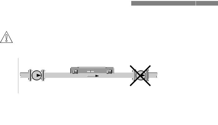
Position of control valve
Always install control valves downstream of the flowmeter in order to avoid cavitation or distortion of the flow profile.
Figure 3-6: Position of control valve
|
03/2013 — 4000972603 — MA OPTISONIC 6300 P R03 en |
www.krohne.com |
15 |
|
3 INSTALLATION FOR FLOW MEASUREMENT |
OPTISONIC 6300 P |
Position of pump
CAUTION!
Never install the flowmeter at the suction side of a pump in order to avoid cavitation or flashing in the flowmeter.
Figure 3-7: Position of pump
Determine data and dimensions of pipe
CAUTION!
The next data must be available before proceeding with Step 2.
•Use the supplied tape measure to determine the outside diameter of the pipe.
•Determine the pipe wall thickness. A pipe wall thickness gauge or pipe tables can be used for this.
•Find out what the material of the pipe is.
•If the pipe has a liner, find out the liner material and the thickness of the liner.
|
16 |
www.krohne.com |
03/2013 — 4000972603 — MA OPTISONIC 6300 P R03 en |

|
INSTALLATION FOR FLOW MEASUREMENT 3 |
||
|
OPTISONIC 6300 P |
||
3.3 Step 2: Initialise the UFC 300 P converter
Figure 3-8: Keys UFC 300 P
1TFT Display
2Navigation keys
3Quick access keys
4Text and numerical keypad
5On / off button
• Turn on the converter by pressing the on / off button for one second. Wait until the menu appears, this will take approximately 30 seconds.
|
03/2013 — 4000972603 — MA OPTISONIC 6300 P R03 en |
www.krohne.com |
17 |

|
3 INSTALLATION FOR FLOW MEASUREMENT |
OPTISONIC 6300 P |
INFORMATION!
FIRST TIME USE:
When the UFC 300 P converter is started for the first time, the startup menu will be shown. In this menu, set the language, time and date.
To show the menu again at the next startup, select «Settings and information Device Startup sequence? Yes».
First time use
Menu
Language English
Time and date
Units
Continue
13-04-2010 14:11:09 13 MB free
First time use, program the units in the converter
If you use the converter for the first time, it will prompt you for the unit setting automatically. Otherwise go to menu number 2.4.1 («Measurement Setup Units»).
Choose in each line the required unit with the buttons as shown in the next table.
Navigate through the menu
|
Back |
Back one page |
|
|
Up |
Up one line |
|
|
Down |
Down one line |
|
|
Forward |
Enter item to edit or to select it |
|
When editing, only the Back and Forward buttons are functional:
|
Back |
Delete previous character or leave item |
|
|
unchanged when at position one |
||
|
Forward |
Move cursor right, accept item when at |
|
|
last position |
||
|
18 |
www.krohne.com |
03/2013 — 4000972603 — MA OPTISONIC 6300 P R03 en |

|
INSTALLATION FOR FLOW MEASUREMENT 3 |
||
|
OPTISONIC 6300 P |
||
REGULAR USE:
If the device has been used before, the screen will look like:
Menu
Installation
Measurement
View logged data
File Management
Settings and information
13-04-2010 14:11:09 13 MB free
Program the converter
CAUTION!
Normally, all settings are saved in a site file. To load the default values, load the default site file via «Measurement > Load site».
If needed you can recover the factory settings for the site file via «Settings and Information > Load factory settings». Previous saved site files are kept during this process.
• Select «Installation» from the main menu.
Menu
Installation
Measurement
View logged data
File management
Settings & information
13-04-2010 14:11:09 13 MB free
The next screen is shown:
1.1
1 pipe / 1 path
1 pipe / 2 path
2 pipes
13-04-2010 14:11:09 13 MB free
See the next figure for an explanation of the options:
|
03/2013 — 4000972603 — MA OPTISONIC 6300 P R03 en |
www.krohne.com |
19 |

|
3 INSTALLATION FOR FLOW MEASUREMENT |
OPTISONIC 6300 P |
Figure 3-9: System configuration possibilities
11 pipe / 1 path
21 pipe / 2 path
32 pipes
•Choose the desired configuration.
•In the next screen, fill in the data that was found in Step 1.
|
1.2 |
|||
|
Pipe tag |
Pipe1 |
||
|
Outer diameter |
100.00 mm |
||
|
Material |
Carbon steel |
||
|
Wall thickness |
5.00 mm |
||
|
Liner material |
Epoxy |
||
|
Liner thickness |
0.50 mm |
||
|
< Previous | Next > |
|||
|
13-04-2010 14:11:09 |
13 MB free |
||
|
Pipe tag |
Enter a name for the pipe |
||
|
Press again » » and » «. |
|||
|
Outer diameter |
Use the outside diameter |
||
|
Material |
Choose the right material |
||
|
Wall thickness |
Fill in the pipe wall thickness |
||
|
Liner material |
Select whether there is a liner or not |
||
|
Liner thickness |
Fill in the liner thickness |
||
|
The liner thickness will only be shown if a liner |
|||
|
material is chosen. |
Choose next
|
20 |
www.krohne.com |
03/2013 — 4000972603 — MA OPTISONIC 6300 P R03 en |
![]()
|
INSTALLATION FOR FLOW MEASUREMENT 3 |
||
|
OPTISONIC 6300 P |
||
CAUTION!
Inaccurate input of the outside diameter will affect the accuracy of the measured flow rate.
INFORMATION!
In case of a two pipe configuration, the converter will ask if the data entered for pipe 1 has to be used for pipe 2 too.
Menu 1.2 and 1.3 are shown again to enter the data for the second pipe.
|
1.3 |
|||
|
Fluid |
Water |
||
|
VoS Fluid |
1485.0 m/s |
||
|
Viscosity |
1 mm2/s |
||
|
< Previous | Next > |
|||
|
13-04-2010 14:11:09 |
13 MB free |
||
|
Fluid |
Select the correct fluid from the table. |
||
|
VoS Fluid |
Velocity of Sound of the selected fluid. Only change it if |
||
|
highly accurate values are available, for instance |
|||
|
temperature compensated. |
|||
|
Viscosity |
Only change it if the viscosity is well known. |
||
|
Choose next |
An advise is given in the next menu:
CAUTION!
Find the calibration numbers that are noted on the labels on the cable of each transducer. Make sure that both transducers have the same calibration number as shown by the converter.
1.7
|
Transducer set |
Ta |
|
|
Calibration number |
522505050 |
|
|
Number of traverses |
2 |
|
|
< Previous | Next > |
||
|
13-04-2010 14:11:09 |
13 MB free |
CAUTION!
Normally, do not change the settings in this menu.
INFORMATION!
In case of a two sensor configuration, this loop will be shown twice. After installing the first transducer the converter will produce a second advice for the second installation.
|
Transducer set |
Select the value that is on the label on the transducer |
|
cable. |
|
|
Note: A maximum of three transducer sets can be |
|
|
programmed in the converter, called Ta, Tb or Tc. |
|
03/2013 — 4000972603 — MA OPTISONIC 6300 P R03 en |
www.krohne.com |
21 |
|
3 INSTALLATION FOR FLOW MEASUREMENT |
OPTISONIC 6300 P |
|
Calibration number |
Compare the calibration number with the number on the |
||||||||||||||||||||||||||||||||||||||||||||||||||||||||||||||||||||||||||||||||||||||||
|
transducer cable. If needed, select a different transducer |
|||||||||||||||||||||||||||||||||||||||||||||||||||||||||||||||||||||||||||||||||||||||||
|
set to change the calibration number. |
|||||||||||||||||||||||||||||||||||||||||||||||||||||||||||||||||||||||||||||||||||||||||
|
Number of traverses |
1 traverse = Z mode |
||||||||||||||||||||||||||||||||||||||||||||||||||||||||||||||||||||||||||||||||||||||||
|
2 traverses = V mode |
|||||||||||||||||||||||||||||||||||||||||||||||||||||||||||||||||||||||||||||||||||||||||
|
4 traverses = W mode |
|||||||||||||||||||||||||||||||||||||||||||||||||||||||||||||||||||||||||||||||||||||||||
|
See figure below for an explanation of the number of |
|||||||||||||||||||||||||||||||||||||||||||||||||||||||||||||||||||||||||||||||||||||||||
|
traverses. |
|||||||||||||||||||||||||||||||||||||||||||||||||||||||||||||||||||||||||||||||||||||||||
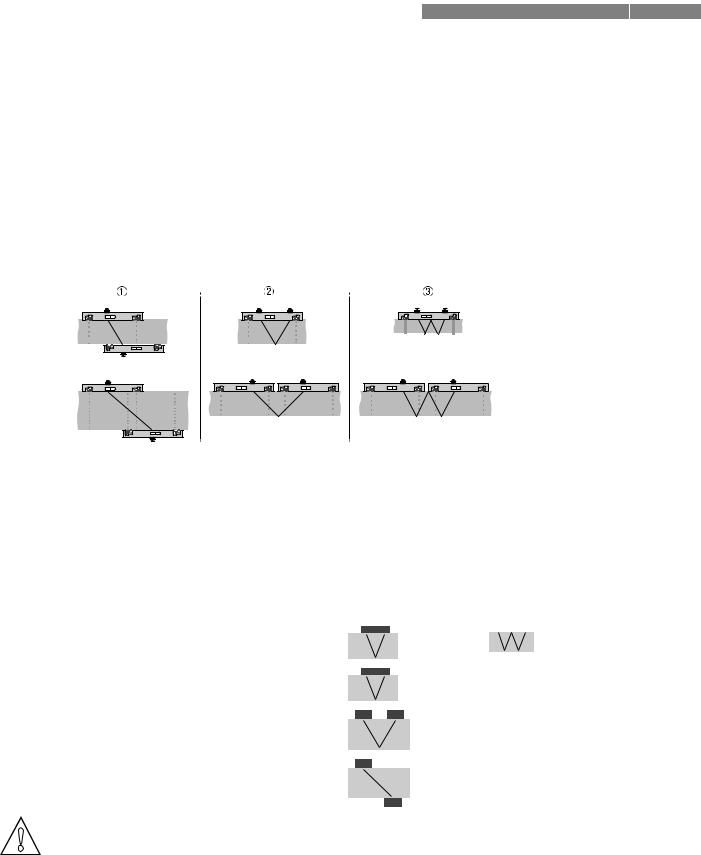
Figure 3-10: Number of traverses
11 traverse (Z mode)
22 traverses (V mode)
34 traverses (W mode)
The best suitable sensor is automatically selected from the available sensor types in the converter and the appropiate number of traverses is indicated. If none of the sensors is suitable, the converter will show «Transducer set : None».
|
Pipe |
Available sensor |
Traverse mode |
||||||||
|
DN15…150 |
Small 2 MHz, 1 rail |
|||||||||
|
DN50…250 |
Medium 1 MHz, 1 rail |
|||||||||
|
DN200…750 |
Medium 1 MHz, 2 rails |
|||||||||
|
DN400…1500 |
Medium 1 MHz, 2 rails |
|||||||||
CAUTION!
Normally, install the sensors as advised. If the quality of the pipe walls is poor and / or in case of scaling inside the pipes, try to decrease the amount of traverses or (if possible) use a medium sensor instead of a small sensor.
|
22 |
www.krohne.com |
03/2013 — 4000972603 — MA OPTISONIC 6300 P R03 en |
|
INSTALLATION FOR FLOW MEASUREMENT 3 |
||
|
OPTISONIC 6300 P |
||
• Press Next to go to the next menu:
1.8
Advised sensor position
34.30 mm Signal quality
0%
< Previous | Next >
13-04-2010 14:11:09 13 MB free
|
Advised distance [mm] |
Number of rails needed |
|
< 190 |
1 |
|
≥ 190 |
2 |
INFORMATION!
The maximum distance that can be covered with 1 rail is 195 mm.
The minimum distance for two rails is 180 mm.
INFORMATION!
On request it is possible to use the large rail of the OPTISONIC 6300 with 0,5 MHz transducers. Using this you can measure up to DN4000.
3.4 Step 3: Mount the sensor rails
Before mounting the rails, determine the colors on the connectors of the transducers. Make sure that the blue transducer is upstream and the green transducer is downstream.
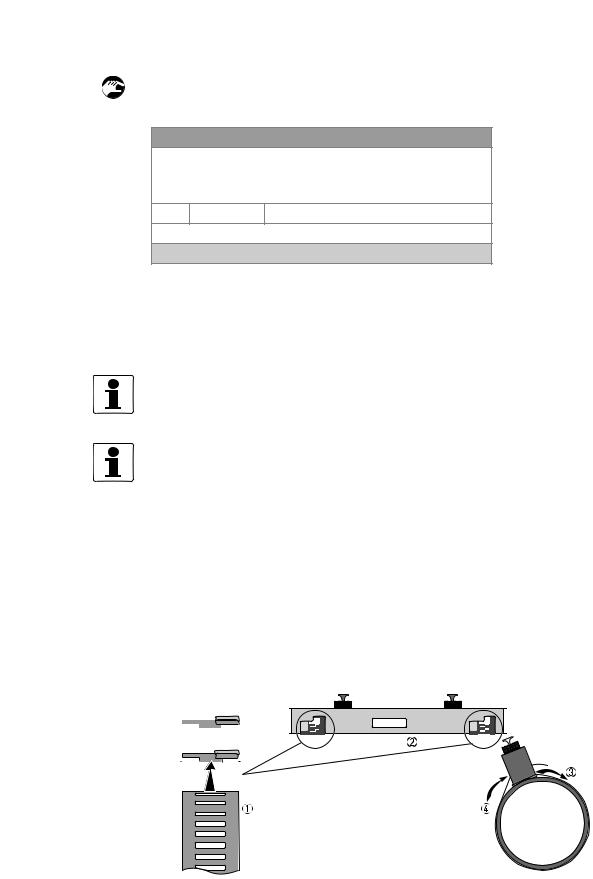
Installation with metal straps (DN15…250)
Put the metal straps around the pipe. Put the sensor rail(s) on the pipe including the transducers with fixed cables.
|
03/2013 — 4000972603 — MA OPTISONIC 6300 P R03 en |
www.krohne.com |
23 |
|
3 INSTALLATION FOR FLOW MEASUREMENT |
OPTISONIC 6300 P |
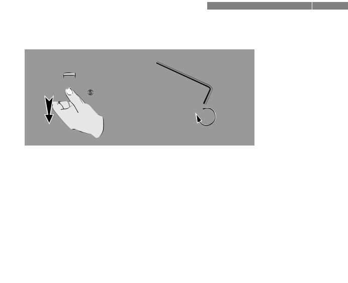
||||||||||||||||||||||||||||||||||
1Insert straps in the lower opening.
2Repeat the same for the other strap.
3Pull the straps around the pipe.
4Insert the straps in the upper opening.
5Pull the straps tight.
6Use an allan key nr 5 (or a big screwdriver) to fixate the rails.
|
24 |
www.krohne.com |
03/2013 — 4000972603 — MA OPTISONIC 6300 P R03 en |

|
INSTALLATION FOR FLOW MEASUREMENT 3 |
||
|
OPTISONIC 6300 P |
||
Installation with textile straps (> DN250)
For pipe diameters above DN250, the textile straps must be used.
1Insert the long strap in the upper opening.
2Insert the short strap in the lower opening at the other side of the rail.
3Pull the strap around the pipe.
4Fix the strap, as indicated below.
1Push lever to create a opening.
2Insert the textile strap as indicated.
3Release lever.
4Pull strap tight.
5Use an allan key nr 5 (or a big screwdriver) to fixate the rails.
|
03/2013 — 4000972603 — MA OPTISONIC 6300 P R03 en |
www.krohne.com |
25 |

|
3 INSTALLATION FOR FLOW MEASUREMENT |
OPTISONIC 6300 P |
3.4.1 2 or 4 traverses with 1 rail
Applicable diameters with one rail:
|
Number of |
Diameter range |
|
traverses |
|
|
2 |
DN15…250 |
|
4 |
DN15…150 |
Put the first transducer at position «0». Put the other transducer at the advised distance, shown on the screen in Step 2. See the figures below.
Figure 3-11: Advised distance with one rail
1 Advised distance is measured from center first transducer to indicator at second transducer.
• Unlock the transducer by turning the locking knob 2 counter clockwise.
•Slide the transducer 1 to the new position 3.
•Lock the transducer by turning the locking knob 2 clockwise.
|
26 |
www.krohne.com |
03/2013 — 4000972603 — MA OPTISONIC 6300 P R03 en |
|
INSTALLATION FOR FLOW MEASUREMENT 3 |
||
|
OPTISONIC 6300 P |
||
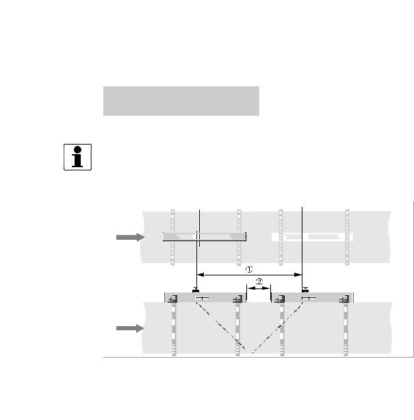
3.4.2 2 traverses with 2 rails
Applicable diameters with two rails:
|
Number of |
Diameter range |
|
traverses |
|
|
2 |
DN200…750 |
INFORMATION!
The two rails must be installed in a straight line.
Figure 3-12: Mounting 2 rails in V-mode (2 traverses)
1Advised distance
2Distance between 2 rails
• Mount the first rail on the pipe. Make sure that you mount the rail in line with the pipe!
•Position the left transducer in any position X (see next section).
•Mount the second rail (align it with the first rail) at a distance 2 to arrange that the transducer in the second rail is within the range it can be moved.
•The advised distance 1 is defined from the center of the left transducer to the left side of the right transducer. Put the second transducer at position Z = advised distance 1 + X — distance 2 — 415 mm / 16.3″.
|
03/2013 — 4000972603 — MA OPTISONIC 6300 P R03 en |
www.krohne.com |
27 |
 Loading…
Вы здесь
Каталог инструкций » K » KROHNE » Оборудование KROHNE » KROHNE OPTISONIC 6300 RU » Страница инструкции 1
-

1
-
2
-
3
-
4
-
5
-
6
-
7
-
8
-
9
-
10
-
11
-
12
-
13
-
14
-
15
-
16
-
17
-
18
-
19
-
20
-
21
-
22
-
23
-
24
-
25
-
26
-
27
-
28
-
29
-
30
-
31
-
32
-
33
-
34
-
35
-
36
-
37
-
38
-
39
-
40
-
41
-
42
-
43
-
44
-
45
-
46
-
47
-
48
-
49
-
50


- 1
- 2
- 3
- ››
Распечатать
Страница 1 из
- << Предыдущая
- Следующая >>

Optisonic 6300, Ультразвуковой накладной расходометр в инструкции по эксплуатации KROHNE OPTISONIC 6300 RU
Ультразвуковой накладной расходометр
ER 3.4.0_
OPTISONIC 6300
Руководство по эксплуатации
© KROHNE 10/2011 4001688601 MA OPTISONIC 6300 R01 ru
- << Предыдущая
- Следующая >>
KROHNE OPTISONIC 6300 Measuring Instruments PDF User Guides and Manuals for Free Download: Found (8) Manuals for KROHNE OPTISONIC 6300 Device Model (Handbook, Supplementary Instructions Manual)
More Measuring Instruments Device Models:
-
Fluke
1587
TESTMIN MAXHOLDTESTMIN MAXHOLDTESTMIN MAXHOLDTESTMIN MAXHOLDTESTMIN MAXHOLDSmoothing (Power Up Option)PN 2405362 April 2005©2005 Fluke Corporation. All rights reserved. Printed in USA.Visit Fluke’s website @ www.fluke.com1587/1577 Insulation TesterQuick Reference GuideSee Users Manual for «Safety Information …
1587 Test Equipment, 2
-
Agilent Technologies
PSA Series
External Source ControlPersonality GuideAgilent TechnologiesPSA Series Spectrum AnalyzersOption 215This manual provides documentation for the following instruments with Option 215 Installed:PSA SeriesE4440A (3 Hz — 26.50 GHz)E4443A (3 Hz — 6.70 GHz)E4445A (3 Hz — 13.20 GHz)E4446A (3 Hz — 44.00 GHz)E4447A (3 Hz — 42.98 …
PSA Series Measuring Instruments, 78
-
Ralston Instruments
FieldLab
For all models of the Ralston FieldLab Pressure Gauge (FLP1)Pour tous les modèles de manomètres Ralston FieldLab Pressure (FLP1)Para todos los modelos de Ralston Pressure FieldLab (FLP1)適用於 Ralston FieldLab 壓力錶 (FLP1) 的所有型號Для всех моделей манометра Ralston FieldLab (FLP1) …
FieldLab Measuring Instruments, 56
-
rainforest
EMU
EMU™ Quick Start 34 W 7th Ave, Vancouver, BC, Canada V5Y 1L6 [email protected] 1-604-630-4287 EMU™ Energy Monitoring Unit Quick Start Guide FCC/IC Notices Changes or modifications not expressly approved by the manufacturer could void the user’s authority to opera …
EMU Measuring Instruments, 2
Recommended Documentation: