-
Contents
-
Table of Contents
-
Bookmarks
Quick Links
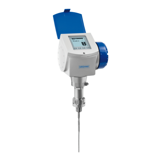
OPTIFLEX 1300 C
OPTIFLEX 1300 C
OPTIFLEX 1300 C
OPTIFLEX 1300 C
Guided Radar (TDR) Level Meter
for distance, level, volume and mass measurement of liquids, liquid interface, pastes
and solids
© KROHNE 09/2010 — 4000172305 — HB OPTIFLEX 1300 R06 en
Handbook
Handbook
Handbook
Handbook
Related Manuals for KROHNE OPTIFLEX 1300 C
Summary of Contents for KROHNE OPTIFLEX 1300 C
-
Page 1
OPTIFLEX 1300 C OPTIFLEX 1300 C Handbook Handbook Handbook Handbook Guided Radar (TDR) Level Meter for distance, level, volume and mass measurement of liquids, liquid interface, pastes and solids © KROHNE 09/2010 — 4000172305 — HB OPTIFLEX 1300 R06 en… -
Page 2
All rights reserved. It is prohibited to reproduce this documentation, or any part thereof, without the prior written authorisation of KROHNE Messtechnik GmbH. Subject to change without notice. Copyright 2010 by KROHNE Messtechnik GmbH — Ludwig-Krohne-Str. 5 — 47058 Duisburg (Germany) www.krohne.com 09/2010 — 4000172305 — HB OPTIFLEX 1300 R06 en… -
Page 3: Table Of Contents
CONTENTS OPTIFLEX 1300 C 1 Safety instructions 1.1 Intended use ……………………6 1.2 Certification ……………………6 1.3 Electromagnetic compatibility ………………6 1.4 Safety instructions from the manufacturer …………..7 1.4.1 Copyright and data protection ………………..7 1.4.2 Disclaimer ……………………..7 1.4.3 Product liability and warranty ………………..
-
Page 4
CONTENTS OPTIFLEX 1300 C 4 Electrical connections 4.1 Safety instructions………………….55 4.2 Electrical installation: outputs 1 and 2 …………….55 4.3 Electrical connection for current output …………… 56 4.3.1 Non-Ex……………………… 56 4.3.2 Ex i ……………………….56 4.3.3 Ex d ……………………….56 4.3.4 PROFIBUS PA…………………… -
Page 5
CONTENTS OPTIFLEX 1300 C 6.4.12 How to decrease the length of probes…………….103 6.5 Service mode …………………… 104 6.6 Errors……………………..105 6.6.1 General information………………….105 6.6.2 Error handling……………………107 7 Service 7.1 Periodic maintenance………………..111 7.2 Keep the device clean………………..111 7.3 How to replace device components ……………. -
Page 6: Safety Instructions
SAFETY INSTRUCTIONS OPTIFLEX 1300 C 1.1 Intended use This TDR level transmitter measures distance, level, mass and volume of liquids, pastes, slurries, granulates and powders. It can also measure level and interface of liquids at the same time. It can be installed on tanks, silos and open pits.
-
Page 7: Safety Instructions From The Manufacturer
SAFETY INSTRUCTIONS OPTIFLEX 1300 C 1.4 Safety instructions from the manufacturer 1.4.1 Copyright and data protection The contents of this document have been created with great care. Nevertheless, we provide no guarantee that the contents are correct, complete or up-to-date.
-
Page 8: Product Liability And Warranty
SAFETY INSTRUCTIONS OPTIFLEX 1300 C 1.4.3 Product liability and warranty The operator shall bear responsibility for the suitability of the device for the specific purpose. The manufacturer accepts no liability for the consequences of misuse by the operator. Improper installation and operation of the devices (systems) will cause the warranty to be void. The respective «Standard Terms and Conditions»…
-
Page 9: Warnings And Symbols Used
SAFETY INSTRUCTIONS OPTIFLEX 1300 C 1.4.5 Warnings and symbols used Safety warnings are indicated by the following symbols. DANGER! This information refers to the immediate danger when working with electricity. DANGER! This warning refers to the immediate danger of burns caused by heat or hot surfaces.
-
Page 10: Device Description
DEVICE DESCRIPTION OPTIFLEX 1300 C 2.1 Scope of delivery INFORMATION! Check the packing list to check if you received completely all that you ordered. Figure 2-1: Scope of delivery for compact version 1 Signal converter and probe — compact version.
-
Page 11
DEVICE DESCRIPTION OPTIFLEX 1300 C Figure 2-2: Scope of delivery for the remote housing version 1 Signal converter and probe How to assemble the single rod probe 2 Probe segments. For the assembly procedure of the single rod probe, refer to (single-piece probe) on page 35. -
Page 12: Device Description
DEVICE DESCRIPTION OPTIFLEX 1300 C 2.2 Device description The TDR level transmitter is designed to measure the distance, level, interface, mass and volume of liquids, pastes, slurries, granulates and powders. TDR level transmitters use a probe to guide a signal to the surface of the measured product. The device has a large choice of probes.
-
Page 13: Visual Check
DEVICE DESCRIPTION OPTIFLEX 1300 C 2.3 Visual Check INFORMATION! Inspect the cartons carefully for damage or signs of rough handling. Report damage to the carrier and to the local office of the manufacturer. Figure 2-3: Visual check 1 Device nameplate (for more data, refer to…
-
Page 14: Nameplates
DEVICE DESCRIPTION OPTIFLEX 1300 C 2.4 Nameplates INFORMATION! Look at the device nameplate to ensure that the device is delivered according to your order. Check for the correct supply voltage printed on the nameplate. 2.4.1 Non-Ex nameplate Figure 2-5: Non-Ex nameplate…
-
Page 15: Installation
INSTALLATION OPTIFLEX 1300 C 3.1 Notes on installation INFORMATION! Inspect the cartons carefully for damage or signs of rough handling. Report damage to the carrier and to the local office of the manufacturer. INFORMATION! Check the packing list to check if you received completely all that you ordered.
-
Page 16: Storage
INSTALLATION OPTIFLEX 1300 C 3.2 Storage WARNING! Do not keep the device in a vertical position. This will damage the probe and the device will not measure correctly. Figure 3-1: Storage conditions 1 Do not bend rod and coaxial probes — support here 2 Storage temperature range: -40…+85°C / -40…+185°F…
-
Page 17: Transport
INSTALLATION OPTIFLEX 1300 C 3.3 Transport Figure 3-3: How to hold the device Figure 3-4: How to hold the device 1 Remove the converter before you lift the device with a hoist. 2 Wind cable probes greater than 400 mm / 16¨ in diameter.
-
Page 18: Pre-Installation Requirements
INSTALLATION OPTIFLEX 1300 C 3.4 Pre-installation requirements INFORMATION! Obey the precautions that follow to make sure that the device is correctly installed. • Make sure that there is sufficent space on all sides. • Protect the signal converter from direct sunlight. If necessary, install the weather protection accessory.
-
Page 19
INSTALLATION OPTIFLEX 1300 C Temperature ranges for gaskets Gasket material Process connection temperature Standard version High-Pressure version High-Temperature and High-Temperature / High-Pressure versions [°C] [°F] [°C] [°F] [°C] [°F] FKM/FPM -40…+200 -40…+390 -40…+150 -40…+300 -40…+300 -40…+570 -20…+200 -4…+390 -20…+150 -4…+300 -20…+300… -
Page 20: General Information For Nozzles
INSTALLATION OPTIFLEX 1300 C 3.5.2 General information for nozzles CAUTION! Follow these recommendations to make sure that the device measures correctly. Figure 3-6: Recommended nozzle dimensions 1 Recommended conditions: h ≤ d, where h is the height of the tank nozzle and d is the diameter of the tank nozzle.
-
Page 21
INSTALLATION OPTIFLEX 1300 C Figure 3-8: Do not put the device near to a product inlet 1 The device is in the correct position. 2 The device is too near to the product inlet. 3 If it is not possible to put the device in the recommended position, install a deflector pipe. -
Page 22: Installation Requirements For Concrete Roofs
INSTALLATION OPTIFLEX 1300 C 3.5.3 Installation requirements for concrete roofs Figure 3-10: Installation on a concrete roof 1 The diameter, d, of the hole must be greater than the thickness, t, of the concrete. 2 If the thickness, t, of the concrete is greater than the diameter, d, of the hole, install the device in a recess.
-
Page 23: How To Attach Probes To The Bottom Of The Tank
INSTALLATION OPTIFLEX 1300 C INFORMATION! If your device has a coaxial probe, you can ignore these installation recommendations. CAUTION! Install coaxial probes in clean liquids that are not too viscous. INFORMATION! If the device has to measure the level of dangerous products (ammonia etc.), we recommend ®…
-
Page 24
INSTALLATION OPTIFLEX 1300 C Double cable Ø4 mm / 0.15¨ Figure 3-13: How to attach a double cable probe to keep it straight The probe counterweight has a hole with an M8 internal thread. You can also select the appropriate options and attach:… -
Page 25
INSTALLATION OPTIFLEX 1300 C Single cable Ø4 mm / 0.15¨ Figure 3-15: How to attach a Ø4 mm / 0.15¨ single cable probe to keep it straight The probe counterweight has a hole with an M8 internal thread. You can also select the… -
Page 26: Standpipes
INSTALLATION OPTIFLEX 1300 C Single cable Ø2 mm / 0.08¨ Figure 3-16: How to attach a Ø2 mm / 0.08¨ single cable probe to keep it straight The probe counterweight has a hole with an M8 internal thread. You can attach:…
-
Page 27
INSTALLATION OPTIFLEX 1300 C Figure 3-18: Basic installation recommendations for standpipes (stilling wells and bypass chambers) 1 Stilling well 2 Bypass chamber 3 Air circulation hole 4 Level of the liquid CAUTION! Installation requirements The standpipe must be electrically conductive. -
Page 28
INSTALLATION OPTIFLEX 1300 C Figure 3-19: Installation recommendations for stilling wells 1 Stilling well in tanks containing one liquid 2 Stilling well in tanks containing more than one liquid 3 Air circulation hole 4 Maximum level of the liquid 5 Liquid circulation hole 6 Distance between holes ≥… -
Page 29
INSTALLATION OPTIFLEX 1300 C Figure 3-20: Floating roofs 1 Sediment 2 Support fixtures 3 Stilling well 4 Floating roof 5 Product 6 Tank Bypass chamber — general notes Figure 3-21: Installation recommendations for bypass chambers 1 Bypass chamber for tanks that contain one liquid 2 Bypass chamber for tanks that contain more than one liquid 3 Distance between holes ≤… -
Page 30
INSTALLATION OPTIFLEX 1300 C Installation on tanks containing one liquid and foam • The bypass chamber must have a process connection that is above the maximum level of liquid. • The bypass chamber must have a process connection that is below the lowest measured level of liquid. -
Page 31: Typical Applications
INSTALLATION OPTIFLEX 1300 C 3.6.4 Typical applications Spherical tanks The device can measure liquid petroleum gas (LPG). This product is stocked in spherical tanks. Figure 3-23: A spherical tank Figure 3-24: How to install the device on a spherical tank 1 Install the device on top of the tank 2 If the top platform has the shape of a nozzle, do not install the process connection too near to the wall.
-
Page 32
INSTALLATION OPTIFLEX 1300 C Horizontal cylindrical tanks Obey the instructions for installation in vertical tanks. Figure 3-25: How to install the device in a horizontal cylindrical tank www.krohne.com 09/2010 — 4000172305 — HB OPTIFLEX 1300 R06 en… -
Page 33: Installation Recommendations For Solids
INSTALLATION OPTIFLEX 1300 C 3.7 Installation recommendations for solids 3.7.1 Nozzles on conical silos We recommend that you prepare the installation when the silo is empty. DANGER! Risk of electrostatic discharge (ESD): Risk of electrostatic discharge (ESD): The device is resistant to electrostatic discharges of up to…
-
Page 34: Traction Loads On The Probe
INSTALLATION OPTIFLEX 1300 C Clearance between the probe and other objects in the tank Probe type Empty space (radius, R ) around the probe [mm] [inches] Single cable Ø4 mm / 0.15¨ 4 Single cable Ø8 mm / 0.3¨ 4…
-
Page 35: How To Install The Device On The Tank
INSTALLATION OPTIFLEX 1300 C 3.8 How to install the device on the tank 3.8.1 How to assemble the single rod probe (single-piece probe) INFORMATION! This procedure is for devices with single rod probes that are not segmented (single-piece probes). Figure 3-27: Equipment needed to assemble the device…
-
Page 36
INSTALLATION OPTIFLEX 1300 C Figure 3-28: Check the order number on each component • Make sure that the housing assembly and the single rod have the same ID numbers. • Remove the sticker from the probe. www.krohne.com 09/2010 — 4000172305 — HB OPTIFLEX 1300 R06 en… -
Page 37
INSTALLATION OPTIFLEX 1300 C Figure 3-29: How to attach the locking nut and union nut • Attach a locking nut and the union nut to the housing assembly. • Tighten these nuts with the two 8 mm open-ended wrenches. 09/2010 — 4000172305 — HB OPTIFLEX 1300 R06 en… -
Page 38
INSTALLATION OPTIFLEX 1300 C Figure 3-30: How to attach the single rod probe to the flange assembly CAUTION! Support the probe. • Attach a locking nut to the single rod. • Attach the single rod to the union nut. Make sure the probe touches the housing assembly. -
Page 39: How To Assemble The Single Rod Probe (Segmented Probe)
INSTALLATION OPTIFLEX 1300 C 3.8.2 How to assemble the single rod probe (segmented probe) INFORMATION! This procedure is for devices with single rod probes that are segmented. Figure 3-31: Equipment needed to assemble the single rod probe (segmented) 1 Converter and process connection…
-
Page 40
INSTALLATION OPTIFLEX 1300 C Figure 3-32: How to assemble the segmented single rod probe: part 1 CAUTION! Make sure that the nuts are tight and the rod probe cannot loosen. • Attach a lock nut to the threaded rod below the process connection. Turn the nut until it is ¾… -
Page 41
INSTALLATION OPTIFLEX 1300 C Figure 3-33: How to assemble the segmented single rod probe: part 2 WARNING! Put a support below the probe to prevent deformation. CAUTION! Make sure that the nuts are tight and the rod probe cannot loosen. -
Page 42: How To Assemble The Segmented Coaxial Probe
INSTALLATION OPTIFLEX 1300 C 3.8.3 How to assemble the segmented coaxial probe Figure 3-34: Equipment needed to assemble the coaxial probe 1 Converter and process connection 2 Top (quantity: 1), middle (quantity: 1 or more) and bottom (quantity: 1) segments of the signal rod 3 Lockwashers (1 pair of washers per probe segment) 4 HC M4×20 screws (1 screw per probe segment)
-
Page 43
INSTALLATION OPTIFLEX 1300 C Figure 3-35: How to assemble the segmented coaxial probe: part 1 CAUTION! Do not attach the screw to the end of the rod segment that has a groove for the attachment of a PTFE spacer. • Use a 2 mm Allen wrench to attach and tighten a HC M4×20 screw at the top of each rod segment (intermediary and end rod segments) •… -
Page 44
INSTALLATION OPTIFLEX 1300 C Figure 3-36: How to assemble the segmented coaxial probe: part 2 WARNING! Be careful when you use the pipe wrenches. Make sure that the measuring tubes have no deformation. CAUTION! Make sure that the screws are tight and the measuring tube cannot loosen. -
Page 45: How To Install A Device With A Flange Connection
INSTALLATION OPTIFLEX 1300 C 3.8.4 How to install a device with a flange connection Equipment needed: • Device • Gasket (not supplied) • Wrench (not supplied) Figure 3-37: Flange connection • Make sure the flange on the nozzle is level.
-
Page 46: How To Install A Device With A Threaded Connection
INSTALLATION OPTIFLEX 1300 C 3.8.5 How to install a device with a threaded connection Equipment needed: • Device • Gasket (not supplied with G (ISO 228) threaded connections) • 50 mm / 2¨ wrench (not supplied) Figure 3-38: Threaded connection •…
-
Page 47: How To Install A Cable Probe In The Tank
INSTALLATION OPTIFLEX 1300 C 3.8.6 How to install a cable probe in the tank Figure 3-39: Wind cable probes and flexible conduits carefully 1 Do not wind cable probes less than 400 mm / 16¨ in diameter. 2 Do not wind the flexible conduit less than 330 mm / 13¨ in diameter.
-
Page 48: Installation Recommendations For Non-Metallic Tanks And Pits
INSTALLATION OPTIFLEX 1300 C 3.8.7 Installation recommendations for non-metallic tanks and pits If you have a device with a single rod or a single cable probe and a thread connection, obey these instructions: • Put a metal sheet between the device and the process connection.
-
Page 49: How To Assemble The Remote Housing
INSTALLATION OPTIFLEX 1300 C 3.8.8 How to assemble the remote housing Figure 3-42: Part 1 of assembly procedure • Attach the wall bracket 1to the flexible conduit. • Tighten the locking nut 2 with a 24 mm wrench. • Attach the wall bracket to a wall or pipe (DN50…100 / 2¨…4¨) 3.
-
Page 50
INSTALLATION OPTIFLEX 1300 C Figure 3-43: Part 2 of the assembly procedure • Attach the housing to the flexible conduit 6. • Tighten the housing locking screw 7. • Attach the flexible conduit to the probe 8. • Tighten the flexible conduit locking screw 9. -
Page 51
INSTALLATION OPTIFLEX 1300 C You can attach the wall bracket of the remote housing to a wall or pipe (DN50…100 / 2¨…4¨). These are the dimensions: Figure 3-44: Dimensions of the wall bracket Dimensions in mm Dimensions [mm] Wall 67.4 126.4… -
Page 52: How To Turn Or Remove The Signal Converter
INSTALLATION OPTIFLEX 1300 C 3.8.9 How to turn or remove the signal converter INFORMATION! The converter turns 360 ° Figure 3-45: How to turn or remove the signal converter Tool: 5 mm Allen wrench How to turn the signal converter •…
-
Page 53: How To Attach The Weather Protection To The Device
INSTALLATION OPTIFLEX 1300 C 3.8.10 How to attach the weather protection to the device Equipment needed: • Device • Weather protection (option) • 10 mm wrench (not supplied) Refer to «Technical data: Dimensions and weight», for the overall dimensions of the weather protection.
-
Page 54: How To Open The Weather Protection
INSTALLATION OPTIFLEX 1300 C 3.8.11 How to open the weather protection Equipment needed: • Weather protection attached to the device. • Large slotted tip screwdriver (not supplied). Figure 3-47: How to open the weather protection 1 Weather protection in its closed position 2 Weather protection in its open position.
-
Page 55: Electrical Connections
ELECTRICAL CONNECTIONS OPTIFLEX 1300 C 4.1 Safety instructions DANGER! All work on the electrical connections may only be carried out with the power disconnected. Take note of the voltage data on the nameplate! DANGER! Observe the national regulations for electrical installations! DANGER! For devices used in hazardous areas, additional safety notes apply;…
-
Page 56: Electrical Connection For Current Output
ELECTRICAL CONNECTIONS OPTIFLEX 1300 C Procedure: • Remove the housing terminal compartment cover 1. • Connect the wires to the device. Obey the national electrical codes. • Make sure that the polarity of the wires is correct. • Attach the ground to 4 or 7. Both terminals are technically equivalent.
-
Page 57: Profibus Pa
ELECTRICAL CONNECTIONS OPTIFLEX 1300 C 4.3.4 PROFIBUS PA For electrical data for PROFIBUS PA networks, refer to the PROFIBUS PA supplement. You can find this documentation on the CD-ROM delivered with the device or it can be downloaded free of charge from the website (Downloadcenter).
-
Page 58: Networks
ELECTRICAL CONNECTIONS OPTIFLEX 1300 C 4.5 Networks 4.5.1 General information ® ® The device uses the HART communication protocol. This protocol agrees with the HART Communication Foundation standard. The device can be connected point-to-point. It can also operate in a multi-drop network of up to 15 devices.
-
Page 59: Multi-Drop Networks
ELECTRICAL CONNECTIONS OPTIFLEX 1300 C 4.5.3 Multi-drop networks Figure 4-5: Multi-drop network (non-Ex) 1 Address of the device (n+1 for multidrop networks) 2 Address of the device (1 for multidrop networks) ® 3 4 mA + HART ® 4 Resistor for HART…
-
Page 60: Fieldbus Networks
ELECTRICAL CONNECTIONS OPTIFLEX 1300 C 4.5.4 Fieldbus networks FOUNDATION Fieldbus™ network (non-Ex) Figure 4-6: FOUNDATION Fieldbus™ network (non-Ex) 1 Field device 2 Junction box 3 H1 network 4 H1/HSE converter 5 High Speed Ethernet (HSE) 6 Workstation INFORMATION! It is necessary to have a separate power supply to energize devices with the FOUNDATION ™…
-
Page 61
ELECTRICAL CONNECTIONS OPTIFLEX 1300 C PROFIBUS PA/DP network (non-Ex) Figure 4-7: PROFIBUS PA/DP network (non-Ex) 1 Field device 2 Bus termination 3 PROFIBUS PA bus segment 4 Segment coupler (PA/DP link) 5 PROFIBUS DP bus line 6 Control system (PLC / Class 1 master device) -
Page 62: Start-Up
START-UP OPTIFLEX 1300 C 5.1 Start-up checklist Check these points before you energize the device: • Are all the wetted components (probe, flange and gaskets) resistant to the product in the tank? • Does the information on the signal converter nameplate agree with the operating data? •…
-
Page 63: Digital Display Screen
START-UP OPTIFLEX 1300 C 5.3 Digital display screen 5.3.1 Local display screen layout Figure 5-1: Local display screen layout 1 Error icon 2 Tag number or menu name 3 Selected menu item (gray text cannot be selected) : scroll up/scroll down 5 Keypad buttons (refer to the table below) 5.3.2 Keypad buttons…
-
Page 64: How To Start The Device
START-UP OPTIFLEX 1300 C 5.3.4 How to start the device • Connect the converter to the power supply. • Energize the converter. After 30 seconds the screen will display «booting up», «starting up» and then the default screen will appear.
-
Page 65: Remote Communication With The Ams™ Device Manager
START-UP OPTIFLEX 1300 C Figure 5-2: Screen from the PACTware™ user interface 1 DTM menu 2 Basic measurement information: level, current output and device status 3 Information for device identification 4 Configuration summary 5.5 Remote communication with the AMS™ Device Manager The AMS™…
-
Page 66: Operation
OPERATION OPTIFLEX 1300 C 6.1 User modes There are 3 modes of operation: • Operator. • Supervisor. • Service. 6.2 Operator mode The operator can choose what information to display. This section shows you: • What each button does in operator mode.
-
Page 67
OPERATION OPTIFLEX 1300 C Information screens for a device with 1 output Text and image Go to % current output Go to Text screen Go to screen screen Level > <Output 1: > Level > (Text Output Function> image) Interface Level >… -
Page 68
OPERATION OPTIFLEX 1300 C Information screens for a device with the second output option Text and image Go to % current output Go to Text screen Go to screen screen Level > <Output 1: output > Level > (Text function>… -
Page 69: Supervisor Mode
OPERATION OPTIFLEX 1300 C 6.3 Supervisor mode 6.3.1 General notes Configure your device in Supervisor Supervisor mode. You can: Supervisor Supervisor • Use the Quick Setup Quick Setup Quick Setup Quick Setup menus to configure your device quickly. For more data about Quick…
-
Page 70: Menu Overview
OPERATION OPTIFLEX 1300 C 6.3.3 Menu overview A Quick Setup Setup Mode Quick Link 1 (default: Error Records) Quick Link 2 (default: Contrast) Quick Link 3 (default: Language) Quick Link 4 (default: Length Unit) Quick Link 5 (default: Display Mode)
-
Page 71: Keypad Functions
OPERATION OPTIFLEX 1300 C 6.3.4 Keypad functions Menu navigation Figure 6-1: Menu navigation 1 Menu selection bar 2 Header bar 3 Menu list 4 Menu item that is not available (in gray text) This is what you see when you are in the list of menus in supervisor mode. The functions of the…
-
Page 72
OPERATION OPTIFLEX 1300 C Lists of parameters in menu items Figure 6-2: Lists of parameters in menu items 1 Parameter selection bar 2 Menu name 3 Parameter used at this time This is what you see when you choose a menu item that has a list of parameters. The functions of… -
Page 73
OPERATION OPTIFLEX 1300 C Values in menu items Figure 6-3: Values in menu items 1 Maximum value 2 Minimum value 3 Cursor on the digit to be changed 4 Menu name 5 Illustration of menu item 6 Error message This is what you see when you choose a menu item that has a value. The functions of the buttons… -
Page 74: Function Description
OPERATION OPTIFLEX 1300 C If you press the buttons for 1 second, you can use these hotkey functions: Hotkey functions in supervisor mode Button Description Function Right Create a quick link Enter Down Screen displays information in English Esc (Escape)
-
Page 75
OPERATION OPTIFLEX 1300 C Menu Step Function Function description Selection list Default Top Product Liquid: Liquid: Alcohol, Liquid: Liquid: Base, Hydrocarbon, Liquid Gas, Mineral Oil, Solvent, Aqueous Solution, Other Solid: Solid: Cereals, Solid: Solid: Minerals, Plastic, Other Application Type: Level, Interface,… -
Page 76
OPERATION OPTIFLEX 1300 C Menu Step Function Function description Selection list Default Sub- Conversion menu submenu [Volume] [Volume] [Volume] [Volume] Do you want to use Select «No». Yes, No a free unit? Table Length Unit m, cm, mm, inch, ft,… -
Page 77
OPERATION OPTIFLEX 1300 C Menu Step Function Function description Selection list Default Mass Table A table that converts product level to product mass. If you selected «Yes» in step 4, make entries in the table in volume units. Press to select a line and press >… -
Page 78
OPERATION OPTIFLEX 1300 C Menu Step Function Function description Selection list Default Output 1 (HART): This assigns a min.-max: Depends on <Function> 20 mA measurement value to 0…90 m / the output 20 mA (output 1). 0…295.29 ft function Output Range This sets the effective 3.8…20.5 mA… -
Page 79
OPERATION OPTIFLEX 1300 C Menu Step Function Function description Selection list Default A.1.6 Snapshot Use this to find and filter out parasite signals in user-defined areas along the probe. Partially empty or completely empty the tank before you do this procedure. -
Page 80
OPERATION OPTIFLEX 1300 C Menu Step Function Function description Selection list Default Quick Link 2 Direct link to an item in Go to a function in Contrast the Advanced Setup the Advanced Setup menu menu and press > for 1 second. You… -
Page 81
OPERATION OPTIFLEX 1300 C Menu Function Function description Selection list Default B.1.5 Internal Test This initiates the hardware test. Read only The device displays the results. Information A summary of information relating to the device. B.2.1 Outputs Analogue output settings. This… -
Page 82
OPERATION OPTIFLEX 1300 C Menu Function Function description Selection list Default B.2.11 Application This displays the description of Read only Mode the algorithm applied to the measurement function and application conditions. This is configured in the Application Application Application Application setup menu. -
Page 83
OPERATION OPTIFLEX 1300 C Menu Function Function description Selection list Default C.1.6 Probe Length Probe length is the distance min-max: blocking Depends on the from the flange face / thread distance…max. probe probe type. stop of the device down to the… -
Page 84
OPERATION OPTIFLEX 1300 C Menu Function Function description Selection list Default C.1.13 Measuring In Direct Direct Direct mode, the device Direct Automatic, Direct, TBF Automatic Mode measures the time it takes to receives a reflection of the signal from the surface of the tank contents. -
Page 85
OPERATION OPTIFLEX 1300 C Menu Function Function description Selection list Default Snapshot Starts or stops the operation of Yes, No the snapshot signal filter. Obey the instructions in the quick setup menu to get snapshot data. For more data, refer to… -
Page 86
OPERATION OPTIFLEX 1300 C Menu Function Function description Selection list Default C.3.5 Error This sets the behaviour of 3.6 mA, 22 mA, Hold 22 mA Handling current output 1 if an error occurs. Hold Hold means that the Hold Hold… -
Page 87
OPERATION OPTIFLEX 1300 C Menu Function Function description Selection list Default C.5.1.2 Display Mode The display screen status will Disable, Auto-Off, Default Disable change after the time given in Screen. C.5.1.3. (time delay). Disable Disable Disable Disable switches off this functionality,… -
Page 88
OPERATION OPTIFLEX 1300 C Data dependencies for the 4 mA settings of outputs 1 and 2 Output function Minimum value Maximum value Default Level <20 mA Setting for Level Volume 0.00 m³ <20 mA Setting for Volume 0 m³ Mass 0.00 kg… -
Page 89: Further Information On Device Configuration
OPERATION OPTIFLEX 1300 C 6.4 Further information on device configuration 6.4.1 Quick Links If you frequently use a menu item, you can create a Quick Link. This lets you quickly find and configure items in the advanced setup menu. Five Quick Link memory spaces are available in the…
-
Page 90: Protection Of The Device Settings
OPERATION OPTIFLEX 1300 C 6.4.2 Protection of the device settings The Passwords Passwords Passwords menu lets you change the supervisor password. Passwords How to change the supervisor password • Go to Supervisor > Advanced setup > Device setup > Passwords > Supervisor Supervisor >…
-
Page 91: Network Configuration
OPERATION OPTIFLEX 1300 C 6.4.3 Network configuration INFORMATION! For more data, refer to Networks on page 58 ® ® The device uses HART communication to send information to HART -compatible equipment. It can operate in either point-to-point or multidrop mode. The device will communicate in ®…
-
Page 92: Linearisation
OPERATION OPTIFLEX 1300 C 6.4.4 Linearisation You can use the linearisation table given in function to make sure that readings are consistently accurate. • Go to Supervisor > Advanced Setup > Installation Setup > Linearisation Table Supervisor > Advanced Setup > Installation Setup > Linearisation Table.
-
Page 93: Level Measurement
OPERATION OPTIFLEX 1300 C Figure 6-5: Distance measurement 1 Tank Height (C.1.2) 2 Reference Offset (C.1.10) 3 Blocking Distance (C.1.9) 4 4 mA Setting (C.3.2 or C.4.2) 5 20 mA Setting (C.3.3 or C.4.3) 6 Maximum effective measuring range 7 Non-measurement zone…
-
Page 94: How To Configure The Device To Measure Volume Or Mass
OPERATION OPTIFLEX 1300 C Figure 6-6: Level measurement 1 Tank Bottom Offset (C.1.11) 2 Tank Height (C.1.2) 3 Blocking Distance (C.1.9) 4 Maximum effective measuring range 5 20 mA Setting (C.3.3 or C.4.3) 6 4 mA Setting (C.3.2 or C.4.2)
-
Page 95: How To Make The Device Follow The Correct Level Or Interface Signal
OPERATION OPTIFLEX 1300 C INFORMATION! When you create a table, get more conversion data for parts of the tank where there are: Surfaces with curves. • Sudden changes in the cross section. • This will make volume measurement more accurate.
-
Page 96
OPERATION OPTIFLEX 1300 C Figure 6-8: Areas on the signal screen 1 Reference signal area (the value cannot be changed) 2 Level signal area (use the distance input function to change the level value) 3 Interface signal area (use the distance input function to change the interface value) -
Page 97: Thresholds And Parasitic Signals
OPERATION OPTIFLEX 1300 C How to adjust the interface distance value to make the device measure interface correctly (devices for interface measurement only). Operator mode • Go to the signal screen in operator mode. For more data, refer to on page 66.
-
Page 98
OPERATION OPTIFLEX 1300 C The electronics of the device amplify the signal. The amplification factor (level of Gain) depends on the strength of the signal. There are 7 levels (1 to 7). A strong signal is given Gain 1, while a weak signal is given Gain 7. When you fill or empty the tank, the device usually identifies the signal. -
Page 99
OPERATION OPTIFLEX 1300 C If the parasite is smaller than the correct level, you can manually change the threshold to find the signal. This procedure tells you how to change the level threshold to find the correct signal: • Look at the signal screen in operator mode. -
Page 100
OPERATION OPTIFLEX 1300 C Interface threshold INFORMATION! If the device is set at the factory to measure interface, you can change the interface threshold. When there is more than one liquid in the tank, the device uses a second threshold to measure interface. -
Page 101: How To Use The Snapshot Function To Filter Parasitic Signals
OPERATION OPTIFLEX 1300 C 6.4.10 How to use the snapshot function to filter parasitic signals The thresholds cannot find the level of the tank contents if it is below a large parasitic signal. This shows the signals as you can see them on an oscilloscope:…
-
Page 102: How To Measure Products With A Low Dielectric Constant (E R )
OPERATION OPTIFLEX 1300 C 6.4.11 How to measure products with a low dielectric constant (ε The device can measure the level of liquids and solids with low dielectric constants. The minimum value depends on the probe type and the measuring mode.
-
Page 103: How To Decrease The Length Of Probes
OPERATION OPTIFLEX 1300 C 6.4.12 How to decrease the length of probes INFORMATION! This information is for: Ø4 mm / 0.15 double cable, • ¨ single rod, • Ø2 mm / 0.08 single cable and • ¨ Ø4 mm / 0.15 single cable probes only •…
-
Page 104: Service Mode
OPERATION OPTIFLEX 1300 C Figure 6-13: Dimensions of the counterweights 1 Ø2 mm / 0.08¨ single cable probe 2 Ø4 mm / 0.15¨ single cable probe 3 Ø4 mm / 0.15¨ double cable probe Dimensions in mm Probe type Dimensions [mm] Øc…
-
Page 105: Errors
OPERATION OPTIFLEX 1300 C 6.6 Errors 6.6.1 General information Indication of errors When the device senses an error or warning condition, it displays an error / warning symbol in the top left corner of the display screen. Figure 6-14: Indication of errors…
-
Page 106
OPERATION OPTIFLEX 1300 C How to find the error records • Enter supervisor mode. • Go to Test > Information > Error Records Test > Information > Error Records Test > Information > Error Records. Test > Information > Error Records •… -
Page 107: Error Handling
OPERATION OPTIFLEX 1300 C How to get more data about the error (error records function) • Select an error log and press ^ ^ ^ ^ to read the help text. Typical data is given in the illustration that follows.
-
Page 108
OPERATION OPTIFLEX 1300 C Description of errors and corrective actions Error Message Error Description Corrective action code Current output Current output saturated at The output is at its maximum Fill the tank or remove some maximum value. output value (20 or 20.5 mA) -
Page 109
OPERATION OPTIFLEX 1300 C Error Message Error Description Corrective action code Level measurement low The product is in the empty Fill the tank to at least the area. The measurement is bottom of the measuring held at the sensor length. -
Page 110
OPERATION OPTIFLEX 1300 C Error Message Error Description Corrective action code Level pulse lost This shows that the device The device continues to lost the level signal in direct measure in TBF mode. If the mode but finds the signal for device does not measure the end of the probe. -
Page 111: Service
SERVICE OPTIFLEX 1300 C 7.1 Periodic maintenance No maintenance is necessary. 7.2 Keep the device clean DANGER! Risk of electrostatic discharge from the plastic sun cover and the conduit of the remote housing option. WARNING! Do not clean plastic parts in a hazardous area.
-
Page 112: Replacement Of The Display Cover
SERVICE OPTIFLEX 1300 C 7.3.2 Replacement of the display cover Figure 7-1: Removal of the device display cover www.krohne.com 09/2010 — 4000172305 — HB OPTIFLEX 1300 R06 en…
-
Page 113
SERVICE OPTIFLEX 1300 C Equipment needed (not supplied): • Slotted tip screwdriver. • 3 mm Allen wrench (for steps 2 and 4). WARNING! Disconnect the power supply How to remove the display 1 Remove the 2 pins on the blue sun cover with a slotted tip screwdriver. Remove the sun cover. -
Page 114: Replacement Of The Complete Electonic Module
SERVICE OPTIFLEX 1300 C 7.3.3 Replacement of the complete electonic module Figure 7-2: Removal of the complete electronic module www.krohne.com 09/2010 — 4000172305 — HB OPTIFLEX 1300 R06 en…
-
Page 115
SERVICE OPTIFLEX 1300 C Equipment needed (not supplied): • 3 mm Allen wrench (for steps 1 and 4). How to remove the back end and microwave unit 1 Loosen the screw on the display. Open the display. 2 Disconnect the power supply connector from the electronics block. -
Page 116: Replacement Of The Terminal Module
SERVICE OPTIFLEX 1300 C 7.3.4 Replacement of the terminal module Figure 7-3: Removal of the terminal module www.krohne.com 09/2010 — 4000172305 — HB OPTIFLEX 1300 R06 en…
-
Page 117
SERVICE OPTIFLEX 1300 C Equipment needed (not supplied): • 2.5 mm Allen wrench for Aluminium (painted) housings; 3 mm Allen wrench for Stainless Steel housings (for step 1). • Small slotted tip screwdriver (for step 3). • TORX T10 wrench (for step 5). -
Page 118: Spare Parts Availability
SERVICE OPTIFLEX 1300 C 7.4 Spare parts availability The manufacturer adheres to the basic principle that functionally adequate spare parts for each device or each important accessory part will be kept available for a period of 3 years after delivery of the last production run for the device.
-
Page 119
SERVICE OPTIFLEX 1300 C Part numbers for spare parts Item Description Quantity Part reference number Complete electronic module XF7140000000040000 Screws for the combined back end and HF modules F3177360000 HMI cover and cable (aluminium housing) XF7140000000050100 HMI cover and cable (stainless steel housing) -
Page 120: List Of Accessories
SERVICE OPTIFLEX 1300 C 7.4.2 List of accessories We supply accessories for this device. When you order accessories, please give the reference numbers that follow: Figure 7-5: Accessories www.krohne.com 09/2010 — 4000172305 — HB OPTIFLEX 1300 R06 en…
-
Page 121
SERVICE OPTIFLEX 1300 C Part numbers for accessories Item Description Quantity Part reference number Plastic sun cover XF714000000000000A Pins for the plastic sun cover F3179990000 Stainless steel weather protection XF7140000000000001 Blind cover (with a gasket and screws) XF714000000000000B Gasket for the blind cover… -
Page 122: Availability Of Services
SERVICE OPTIFLEX 1300 C 7.5 Availability of services The manufacturer offers a range of services to support the customer after expiration of the warranty. These include repair, technical support and training. INFORMATION! For more precise information, please contact your local representative.
-
Page 123: Form (For Copying) To Accompany A Returned Device
SERVICE OPTIFLEX 1300 C 7.6.2 Form (for copying) to accompany a returned device Company: Address: Department: Name: Tel. no.: Fax no.: Manufacturer’s order no. or serial no.: The device has been operated with the following medium: This medium is: water-hazardous…
-
Page 124: Disposal
SERVICE OPTIFLEX 1300 C 7.7 Disposal CAUTION! Disposal must be carried out in accordance with legislation applicable in your country. www.krohne.com 09/2010 — 4000172305 — HB OPTIFLEX 1300 R06 en…
-
Page 125: Technical Data
TECHNICAL DATA OPTIFLEX 1300 C 8.1 Measuring principle This Guided Radar (TDR) level meter has been developed from a proven technology called Time Domain Reflectometry (TDR). The device transmits low-intensity electromagnetic pulses of approximately half a nanosecond width along a rigid or flexible conductor. These pulses move at the speed of light. When the pulses reach the surface of the product to be measured, the pulses are reflected with an intensity that depends on the dielectric constant, ε…
-
Page 126
TECHNICAL DATA OPTIFLEX 1300 C Level measurement principle (direct measurement) Figure 8-1: Level measurement principle 1 Time 0: The electromagnetic (EM) pulse is transmitted by the converter 2 Time 1: The pulse goes down the probe at the speed of light in air, V1… -
Page 127
TECHNICAL DATA OPTIFLEX 1300 C Level and interface measurement principle (direct measurement) Figure 8-2: Level and interface measurement principle (2 liquids in the tank) 1 Time 0: The electromagnetic (EM) pulse is transmitted by the converter 2 Time 1: The pulse goes down the probe at the speed of light in air, V1 3 Time 2: Part of the pulse is reflected at the surface of the top liquid, the remaining pulse goes down the probe 4 Time 3: Part of the pulse goes up the probe at speed, V1. -
Page 128: Technical Data
TECHNICAL DATA OPTIFLEX 1300 C 8.2 Technical data INFORMATION! • The following data is provided for general applications. If you require data that is more relevant to your specific application, please contact us or your local representative. Additional information (certificates, special tools, software,…) and complete product •…
-
Page 129
TECHNICAL DATA OPTIFLEX 1300 C Accuracy Resolution 1 mm / 0.04¨ Repeatability ±1 mm / ±0.04¨ Accuracy (in direct mode) Liquids: Liquids: Liquids: Liquids: ±3 mm / ±0.12¨, when distance < 10 m / 33 ft; ±0.03% of measured distance, when distance > 10 m / 33 ft… -
Page 130
TECHNICAL DATA OPTIFLEX 1300 C Other conditions Other conditions Other conditions Other conditions Dielectric constant (ε Level in direct mode: Level in direct mode: Level in direct mode: Level in direct mode: ≥1.4 for coaxial probe; ≥1.6 for single and double probes… -
Page 131: Input And Output
TECHNICAL DATA OPTIFLEX 1300 C Process connections Thread Thread Thread Thread Single cable Ø2 mm / 0.08¨ G ½; ½ NPT; ½ NPTF (for the HT/HP version) Single cable Ø8 mm / 0.3¨ G 1½; 1½ NPT All other probes G ¾…1½;…
-
Page 132
TECHNICAL DATA OPTIFLEX 1300 C Resolution ±3 µA Temperature drift Typically 50 ppm/K Error signal High: 22 mA; Low: 3.6 mA acc. to NAMUR NE 43 PROFIBUS PA PROFIBUS PA PROFIBUS PA PROFIBUS PA Type 4-wire (+ local HART) level transmitter; Time Domain Reflectometry (TDR) -
Page 133
TECHNICAL DATA OPTIFLEX 1300 C Approvals and certification This device fufills the statutory requirements of the EC directives. The manufacturer certifies successful testing of the product by applying the CE mark. Explosion protection Explosion protection Explosion protection Explosion protection ATEX (approval for fieldbus ATEX II 1 G, 1/2 G, 2 G Ex ia IIC T6…T2;… -
Page 134: Pressure/Temperature Table For Probe Selection
TECHNICAL DATA OPTIFLEX 1300 C 8.3 Pressure/temperature table for probe selection Make sure that the transmitters are used within their operating limits. Figure 8-3: Pressure/temperature table for probe selection 1 Process pressure, P [barg] 2 Process connection temperature, T [°C] 3 All probes 4 High-Pressure (HP) version of the Ø2 mm single cable probe…
-
Page 135: Measurement Limits
TECHNICAL DATA OPTIFLEX 1300 C 8.4 Measurement limits Double cable and double rod probes Figure 8-5: Measurement limits of the double cable probes (on the left side) and double rod probes (on the right side) 1 A1, Top dead zone: A1, Top dead zone: Distance from the flange to the top limit of the measuring range.
-
Page 136
TECHNICAL DATA OPTIFLEX 1300 C Single cable and single rod probes Figure 8-6: Measurement limits of the single cable probes (on the left side) and single rod probes (on the right side) 1 A1, Top dead zone: A1, Top dead zone: A1, Top dead zone: A1, Top dead zone: Distance from the flange to the top limit of the measuring range. -
Page 137
TECHNICAL DATA OPTIFLEX 1300 C Coaxial probe Figure 8-7: Measurement limits of the coaxial probe 1 A1, Top dead zone: A1, Top dead zone: A1, Top dead zone: A1, Top dead zone: Distance from the flange to the top limit of the measuring range. Refer to the notes and table that follow. -
Page 138: Dimensions And Weights
TECHNICAL DATA OPTIFLEX 1300 C 8.5 Dimensions and weights Standard converter Standard converter Standard converter Standard converter Figure 8-8: Standard converter 1 Converter (front view) 2 Flange version for all probes except the Ø2 mm / 0.08¨ single cable probe (right side) 3 Flange version for Ø2 mm / 0.08¨…
-
Page 139
TECHNICAL DATA OPTIFLEX 1300 C Dimensions and weights in mm and kg Dimensions [mm] Weights [kg] Converter 158.5 Flange, single cable Ø2 — 158.5 6…15 version HTor HT/HP Flange, single cable Ø2 — 158.5 5…14 version HP Flange, all other probes 158.5… -
Page 140
TECHNICAL DATA OPTIFLEX 1300 C Remote converter Remote converter Remote converter Remote converter Figure 8-9: Remote housing option 1 Front view 2 Left side 3 Rear view Note: Note: Note: Note: • Refer to «ESD protection and Metaglas® (dual process sealing system for dangerous products) options»… -
Page 141
TECHNICAL DATA OPTIFLEX 1300 C Dimensions and weights in mm and kg Dimensions [mm] Weights [kg] Remote 98.5 150.4 6.6… version 12.8 1 Wall bracket (1.4 kg) + converter support (1.5 kg) + remote probe converter (2.7 kg) + flexible conduit (2 m: 1 kg; 4.5 m: 2.25 kg; 9.5 m: 4.75 kg;… -
Page 142
TECHNICAL DATA OPTIFLEX 1300 C Weather protection option Figure 8-10: Weather protection option 1 Weather protection (rear view) 2 Weather protection (left side) Dimensions and weights in mm and kg Dimensions [mm] Weights [kg] Weather 231.5 protection 1 Radius Dimensions and weights in inches and lb… -
Page 143
TECHNICAL DATA OPTIFLEX 1300 C ESD protection and Metaglas® options Figure 8-11: ESD protection and secondary Metaglas® seal options 1 Optional ESD protection (30 kV) for solid applications 2 Optional Metaglas® (dual process sealing system for dangerous products) CAUTION! The ESD protection and the Metaglas options cannot be fitted to the same device. -
Page 144
TECHNICAL DATA OPTIFLEX 1300 C Single probes Figure 8-12: Single probe options 1 Single rod Ø8 mm / Ø0.3¨ (thread and flange versions). A segmented probe option shown on the right side. An optional protective sheath is available on request for the flange version. -
Page 145
TECHNICAL DATA OPTIFLEX 1300 C Single probes: Dimensions in mm Probes Dimensions [mm] L min. L max. Single rod Ø8 mm 4000 Single rod Ø8 mm (segmented) 6000 Single cable Ø2 mm 35000 Ø14 Single cable Ø4 mm 35000 Ø20 Single cable Ø8 mm… -
Page 146
TECHNICAL DATA OPTIFLEX 1300 C Double probes Figure 8-13: Double probe options 1 Double rod Ø8 mm / Ø0.3¨ (thread and flange versions) 2 Double cable Ø4 mm / Ø0.15¨ (thread and flange versions) 3 Coaxial Ø22 mm / Ø0.9¨ (thread and flange versions) INFORMATION! A wide range of counterweights and anchoring solutions are available. -
Page 147
TECHNICAL DATA OPTIFLEX 1300 C Double probes: Dimensions in mm Probes Dimensions [mm] L min. L max. Double rod Ø8 mm 1000 4000 Double cable Ø4 mm 1000 8000 Ø38 Coaxial Ø22 mm 6000 Coaxial Ø22 mm (segmented) 6000 Ø28… -
Page 148
TECHNICAL DATA OPTIFLEX 1300 C Probe end options for cable probes: single cable Ø4 mm/0.15¨ Figure 8-14: Probe end options for cable probes: single cable Ø4 mm/0.15¨ 1 Standard counterweight 2 Threaded end 3 Crimped end 4 Open end 5 Turnbuckle… -
Page 149
TECHNICAL DATA OPTIFLEX 1300 C Probe end options for cable probes: single cable Ø8 mm/0.3¨ Figure 8-15: Probe end options for cable probes: single cable Ø8 mm/0.3¨ 1 Standard counterweight 1 2 Standard counterweight 2 3 Turnbuckle 4 Chuck 5 Threaded end… -
Page 150
TECHNICAL DATA OPTIFLEX 1300 C Probe end options for cable probes: double cable Ø4 mm/0.15¨ Figure 8-16: Probe end options for cable probes: double cable Ø4 mm/0.15¨ 1 Standard counterweight 2 Threaded end 3 Turnbuckle Dimensions in mm Probe end type… -
Page 151
TECHNICAL DATA OPTIFLEX 1300 C Probe weights Probes Min. process connection size Weights Thread Flange [kg/m] [lb/ft] Single cable Ø2 mm / 0.08¨ G ½A; ½ NPTF DN25 in PN16, PN40, PN63 or 0.016 0.01 PN100; 1¨ in 150 lb, 600 lb, 900 lb, 1500 lb or 2500 lb;… -
Page 152: Appendix
9.1 Order form You can help us to assist you as quickly as possible by giving us a few items of information. Then just fax them to us. Your personal KROHNE consultant will contact you within 24 hours. 9.1.1 Device data…
-
Page 153: Rating Data
APPENDIX OPTIFLEX 1300 C 9.1.2 Rating data Product name: Operating pressure: Rated pressure: Process connection temperature: Ambient temperature: Viscosity: Measurand (level, volume,…): Tank height: Comments (indoors, exposed to weather, …): 9.1.3 Contact data Company: Contact person: Telephone number: Fax number: E-mail: 9.2 Glossary…
-
Page 154
APPENDIX OPTIFLEX 1300 C Electromagnetic compatibility Electromagnetic compatibility Defines how much a device influences or is influenced by other devices that Electromagnetic compatibility Electromagnetic compatibility generate electromagnetic fields during operation. Refer to European standard EN 61326-1 and EN 61326-2-3 for further details. -
Page 155
APPENDIX OPTIFLEX 1300 C Hazardous area Hazardous area An area with a potentially explosive atmosphere. Trained personnel can Hazardous area Hazardous area install and use a device in this area. The device must be ordered with the appropriate options. The device requires approvals (ATEX, IEC Ex, FM, CSA, NEPSI etc.) related to site specifications. -
Page 156
APPENDIX OPTIFLEX 1300 C Sensor length Sensor length Length, L’, of from the face of the flange to end of the guide. If you ordered Sensor length Sensor length a cable probe, this does not include the counterweight. Refer to the diagram at the end of this section. -
Page 157
APPENDIX OPTIFLEX 1300 C Figure 9-2: Measurement definitions 1 1 Interface distance 2 Distance 3 Flange facing 4 Gas (Air) 5 Interface 6 Sensor length, L’ 7 Probe length, L 8 Tank height 9 Ullage volume or mass Figure 9-3: Measurement definitions 2… -
Page 158: Notes
NOTES OPTIFLEX 1300 C www.krohne.com 09/2010 — 4000172305 — HB OPTIFLEX 1300 R06 en…
-
Page 159
NOTES OPTIFLEX 1300 C 09/2010 — 4000172305 — HB OPTIFLEX 1300 R06 en www.krohne.com… -
Page 160
Measuring systems for the oil and gas industry • Measuring systems for sea-going tankers Head Office KROHNE Messtechnik GmbH Ludwig-Krohne-Str. 5 D-47058 Duisburg (Germany) Tel.:+49 (0)203 301 0 Fax:+49 (0)203 301 10389 info@krohne.de The current list of all KROHNE contacts and addresses can be found at: www.krohne.com…

Практическое руководство
по монтажу и эксплуатации
OPTIFLEX 1300C
рефлекс-радарных уровнемеров
для измерения уровня, дистанции, объема
жидкостей, раздела фаз, паст и сыпучих
веществ
o
Простая установка
o
Встроенная эксперт-программа
o
Не требуют обслуживания
©
KROHNE 08/2005
7.02534.11.00
RU

Guided Radar (TDR) Level Meter
Supplementary Instructions for ATEX applications
Supplementary Instructions for ATEX applicationsSupplementary Instructions for ATEX applications
Supplementary Instructions for ATEX applications
OPTIFLEX 1300 C
OPTIFLEX 1300 COPTIFLEX 1300 C
OPTIFLEX 1300 C
Supplementary instructions
Supplementary instructions Supplementary instructions
Supplementary instructions
© KROHNE 06/2010 — 4000091403 — AD ATEX OPTIFLEX 1300 R05 en

CONTENTS
2
www.krohne.com 06/2010 — 4000091403 — AD ATEX OPTIFLEX 1300 R05 en
OPTIFLEX 1300 C
1 General safety information 4
1.1 Scope of the document………………………..……………………………………………………………… 4
1.2 Device description ………………………………………………………………………..……………………. 4
1.3 Standards and approvals……….………………………………..……………………………….…………. 4
1.4 Device categories …………………………..……………………………………………………………….…. 5
1.4.1 Ex ia / Ex iaD-approved devices……………………………………………………………………………….... 5
1.4.2 Ex d[ia] / Ex tD[iaD]-approved devices ……………………………………………………………………….. 5
1.4.3 Ex nA devices ………………………………………………………………………………………………………….. 5
1.4.4 Definitions of device categories…………………………………………………………………………….…… 5
1.5 ATEX nameplates……………………..………………………………………………………………………… 6
2 Installation 8
2.1 Precautions……..…………………………………………………………………………………………..……. 8
2.1.1 General notes……………………………………………………………………………………………..…………… 8
2.1.2 Electrostatic discharge…………………………………………………………………………………….………. 8
2.1.3 Special conditions ……………………………………………………………………………………………………. 9
2.2 Operating conditions ………………..…………………………………………………………………..….... 9
2.2.1 Ambient and flange temperature ……………………………………………………………………………….9
2.2.2 Maximum surface temperature of the housing …………………………………………………………. 13
2.2.3 Process pressure…………………………………………………………………………………………..………. 13
3 Electrical connections 14
3.1 General notes ………………………………………………………………..……………………………..…. 14
3.2 Terminal compartment ……………………………………..………………………………..……………. 14
3.2.1 How to open the terminal compartment …………………………………………………………………… 14
3.2.2 How to close the terminal compartment ………………………………………………………………….. 15
3.3 Terminal tightening capacity……………..……………………………….……………………………… 15
3.4 Equipotential bonding system………………………………………………..………………………….. 15
3.5 Ex ia / Ex iaD equipment………….………………………………………………………………………… 15
3.5.1 How to connect the electrical cables ……………………………………………………………………….. 15
3.5.2 Maximum intrinsically-safe values for the electrical circuit……………………………………….. 16
3.5.3 Supply voltage…………………………………………………………………………………………….…………. 16
3.5.4 Electrical schema ………………………………………………………………………………………….………. 17
3.6 Ex d[ia] / Ex tD[iaD] equipment ………………………………………………………………………….. 18
3.6.1 General notes……………………………………………………………………………………………..…………. 18
3.6.2 How to connect the electrical cables ……………………………………………………………………….. 18
3.6.3 Supply voltage…………………………………………………………………………………………….…………. 19
3.6.4 Electrical schema ………………………………………………………………………………………….………. 19
3.7 Ex nA equipment..…………………………………………………………………………………………….. 20
3.7.1 How to connect the electrical cables ……………………………………………………………………….. 20
3.7.2 Supply voltage…………………………………………………………………………………………….…………. 20
3.7.3 Electrical schema ………………………………………………………………………………………….………. 20
4 Start-up 21

CONTENTS
3
www.krohne.com06/2010 — 4000091403 — AD ATEX OPTIFLEX 1300 R05 en
OPTIFLEX 1300 C
5 Service 22
5.1 Periodic maintenance……..………………………………………………………………………………… 22
5.2 Keep the device clean……..………………………………………………………………………………… 22
5.3 Returning the device to the manufacturer…………………………………………………………… 22
5.3.1 General information………………………………………………………………………………………..……… 22
5.3.2 Form (for copying) to accompany a returned device…………………………………………………… 23
1 GENERAL SAFETY INFORMATION
4
OPTIFLEX 1300 C
www.krohne.com 06/2010 — 4000091403 — AD ATEX OPTIFLEX 1300 R05 en
1.1 Scope of the document
These instructions are applicable only to the explosion-protection version of the TDR level
transmitter. For all other data, use the Quick Start and Handbook. If you do not have these
documents, please contact the nearest office or download them from the manufacturer’s
internet site.
1.2 Device description
This device is a 2-wire level transmitter that uses TDR (Time Domain Reflectometry) / Guided
Radar technology. If the device has the FOUNDATION™ Fieldbus or the PROFIBUS PA output
options, it is connected to the fieldbus network as a 4-wire device. The device measures the
level, distance, volume and mass of liquids, liquid gases, pastes, powders, slurries and granular
products. It is also suitable for the continuous and simultaneous measurement of level and
interface of 2 liquids. Measurements are displayed via a DTM (device type manager) for remote
communication or an optional integrated display screen with wizard-driven setup and online
help functions.
The level transmitter is approved for use in potentially explosive atmospheres when equipped
with the appropriate options.
1.3 Standards and approvals
The certificate is given on the CD-ROM supplied with the device. You can also download the
certificate from our internet site.
INFORMATION!
The information in these supplementary instructions only contains the data applicable to
explosion protection. The technical data for the non-Ex version in the Handbook shall be valid in
its current version, provided that it is not rendered invalid or replaced by these supplementary
instructions.
WARNING!
Installation, commissioning and maintenance may only be carried out by «Personnel trained in
explosion protection».
DANGER!
In compliance with European Directive 94/9/EC (ATEX 100a), the ATEX version of the device
described in these Supplementary Instructions conforms to European Standards EN 60079-
0:2006, EN 60079-1:2007, EN 60079-11:2007, EN 60079-15:2005, EN 60079-26:2007, EN 60079-
27:2008, EN 61241-0:2006, EN 61241-1:2004 and EN 61241-11:2006. The Ex ia / Ex iaD and
Ex d[ia] / Ex tD[iaD] versions are certified for use in hazardous areas by the KEMA Quality B.V.
under KEMA 04ATEX1219 X. The Ex nA version is certified for use in zone 2 under our sole
responsibility. For more data, refer to the manufacturer’s declaration given on the CD-ROM
supplied with the device. You can also download the manufacturer’s declaration from our
internet site.
WARNING!
Carefully read the ATEX approval certificate. Obey the boundary conditions.

GENERAL SAFETY INFORMATION 1
5
OPTIFLEX 1300 C
www.krohne.com06/2010 — 4000091403 — AD ATEX OPTIFLEX 1300 R05 en
1.4 Device categories
1.4.1 Ex ia / Ex iaD-approved devices
These devices are suitable for use in potentially explosive atmospheres of all flammable
substances in Gas Groups IIA, IIB and IIC. The Ex ia-approved device is certified for applications
requiring Category 1 G (gases, vapours or mists), 1/2 G or 2 G equipment when fitted with the
appropriate options. The Ex iaD-approved device is certified for applications requiring Category
1 D (dust), 1/2 D or 2 D equipment when fitted with the appropriate options.
1.4.2 Ex d[ia] / Ex tD[iaD]-approved devices
These devices are suitable for use in potentially explosive atmospheres of all flammable
substances in Gas Groups IIA, IIB and IIC. The Ex d[ia]-approved device is certified for
applications requiring Category 1/2 G (gases, vapours or mists) or 2 G equipment when fitted
with the appropriate options. The Ex tD[iaD]-approved device is certified for applications
requiring Category 1/2 D (dust) or 2 D equipment when fitted with the appropriate options.
1.4.3 Ex nA devices
The Ex nA version of this device is suitable for use in potentially explosive atmospheres of all
flammable substances in Gas Group II. It is designed for applications requiring Category 3 G
equipment when fitted with the appropriate options.
1.4.4 Definitions of device categories
Category 1
Category 1Category 1
Category 1
The device is installed in hazardous areas requiring Category 1 G or 1 D equipment.
Category 1/2
Category 1/2Category 1/2
Category 1/2
The signal converter is installed in hazardous areas requiring Category 2 G or 2 D equipment.
The probe is installed in hazardous areas requiring Category 1 G or 1 D equipment.
Category 2
Category 2Category 2
Category 2
The device is installed in hazardous areas requiring Category 2 G or 2 D equipment.
Category 2/3
Category 2/3Category 2/3
Category 2/3
The signal converter is installed in hazardous areas requiring Category 3 G or 3 D equipment.
The probe is installed in hazardous areas requiring Category 2 G or 2 D equipment.
Category 3
Category 3Category 3
Category 3
The device is installed in hazardous areas requiring Category 3 G or 3 D equipment.
INFORMATION!
These devices can also be used for applications requiring Category 2/3 or 3 equipment.
INFORMATION!
These devices can also be used for applications requiring Category 2/3 or 3 equipment.

1 GENERAL SAFETY INFORMATION
6
OPTIFLEX 1300 C
www.krohne.com 06/2010 — 4000091403 — AD ATEX OPTIFLEX 1300 R05 en
1.5 ATEX nameplates
Figure 1-1: Ex ia / Ex iaD nameplate (4…20 mA output)
Figure 1-2: Ex ia / Ex iaD nameplate (PROFIBUS PA or FOUNDATION™ Fieldbus output)
1 ATEX certification agency code
2 Equipment category (explosive atmosphere — gas)
3 Types of device protection including approved Gas Groups (IIA, IIB or IIC) and temperature classes (T6…T3 or T2 — de-
pends on the probe type)
4 Equipment category (explosive atmosphere — dust)
5 Types of device protection (explosive atmosphere — dust)
6 Degree of ingress protection (if fitted with the appropriate cable glands) and maximum surface temperature
7 Intrinsically-safe circuit data
8 Cable entry type and size (Aluminium housing: M26×1.5, M20×1.5, ½NPT or G ½; Stainless steel housing: M25×1.5,
M20×1.5, ½ NPT or G ½)

GENERAL SAFETY INFORMATION 1
7
OPTIFLEX 1300 C
www.krohne.com06/2010 — 4000091403 — AD ATEX OPTIFLEX 1300 R05 en
Figure 1-3: Ex d[ia] / Ex tD[iaD] nameplate (4…20 mA output)
Figure 1-4: Ex nA nameplate (4…20 mA output)
1 ATEX certification agency code
2 Equipment category (explosive atmosphere — gas)
3 Types of device protection including approved Gas Groups (IIA, IIB or IIC) and temperature classes (T6…T3 or T2 — de-
pends on the probe type)
4 Equipment category (explosive atmosphere — gas), types of device protection including approved Gas Groups (IIA, IIB
or IIC) and temperature classes (T6…T3 or T2 — depends on the probe type)
5 Equipment category (explosive atmosphere — dust)
6 Types of device protection (explosive atmosphere — dust)
7 Degree of ingress protection (if fitted with the appropriate cable glands) and maximum surface temperature
8 Maximum voltage in accordance with EN 60079-0
9 Minimum waiting time after power-off before it is safe to open the terminal compartment
10 Cable entry type and size (Aluminium housing: M26×1.5, M20×1.5, ½ NPT or G ½; Stainless steel housing: M25×1.5,
M20×1.5, ½ NPT or G ½)
2 INSTALLATION
8
OPTIFLEX 1300 C
www.krohne.com 06/2010 — 4000091403 — AD ATEX OPTIFLEX 1300 R05 en
2.1 Precautions
2.1.1 General notes
2.1.2 Electrostatic discharge
Take the necessary antistatic precautions if you:
• handle,
• install or
• use
the device in potentially explosive atmospheres. Do not install in a location (near to ventilation
systems, for example) where the electrostatic charge can increase.
WARNING!
When you install the device, obey the conditions in the EC-Type Examination certificate. These
conditions include:
•
The special conditions for safe use.
•
The Essential Health and Safety Requirements.
The certificate is given on the CD-ROM supplied with the device. You can also download the
certificate from our internet site.
DANGER!
This installation must agree with EN 60079-14: Explosive atmospheres — Part 14: Electrical
installations design, selection and erection and EN 61241-14: Electrical apparatus for use in the
presence of combustible dust — Part 14: Selection and installation.
DANGER!
Risk of electrostatic discharge from the blue plastic sun cover, the conduit of the remote housing
option and the optional plastic protective sheath for the single rod probe. Make sure that all
personnel and equipment are correctly grounded.
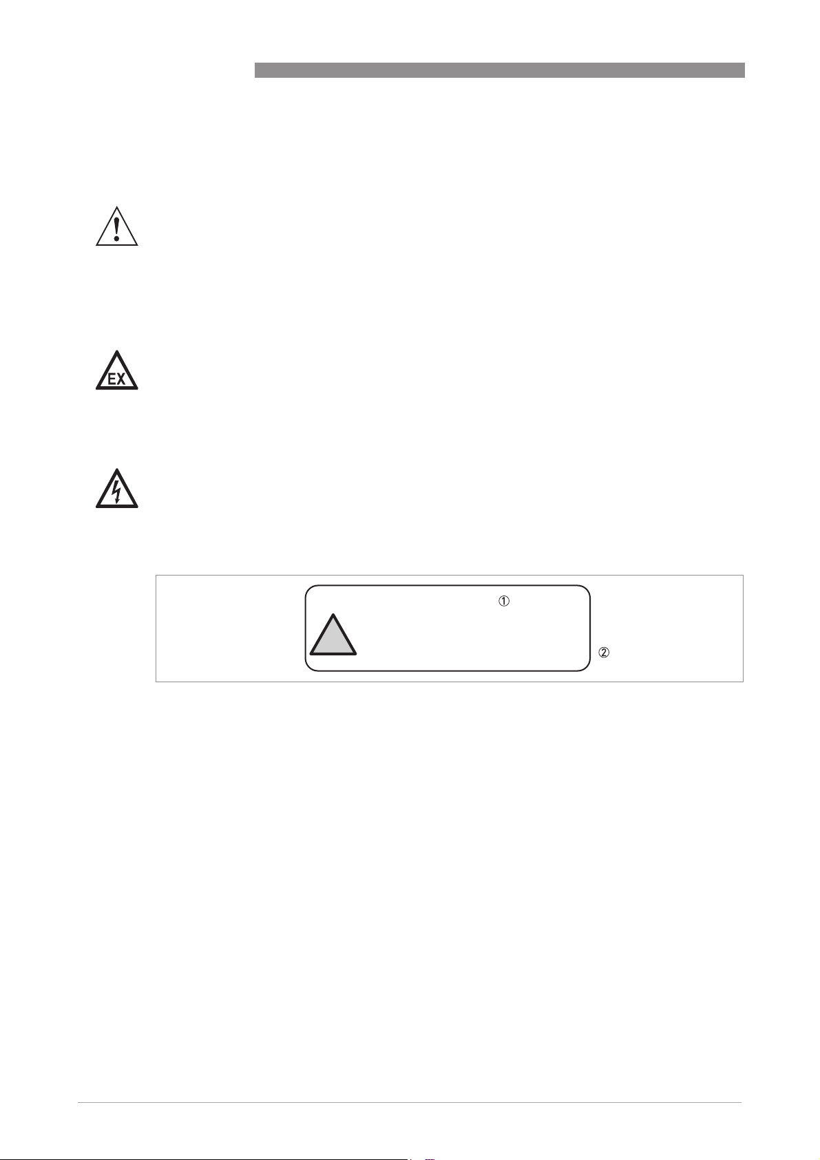
Figure 2-1: ESD warning sticker (below the device nameplate)
1 Text: Plastic Parts
2 Text: Warning! Potential electrostatic hazard — see instructions
PLASTIC PARTS
WARNING:
POTENTIAL ELECTROSTATIC HAZARD
SEE INSTRUCTIONS
!
 Loading…