Hide thumbs
Also See for VS mini J7:
- Manual (116 pages)
-
Contents
-
Table of Contents
-
Troubleshooting
-
Bookmarks
Related Manuals for Omron VS mini J7
Summary of Contents for Omron VS mini J7
-
Page 1
Manual No. I63E-EN-01 VS mini J7 Compact General Purpose Inverter USER’S ManUal… -
Page 2
Please read this manual thoroughly and handle and operate the product with care. 1. To ensure safe and proper use of the OMRON-YASKAWA Inverters, please read this USER’S MANUAL (Cat. No. I63-EN-01) to gain sufficient knowledge of the devices, safety information, and precautions before actual use. -
Page 3
OMRON-YASKAWA Product References All OMRON-YASKAWA products are capitalized in this manual. The word “Unit” is also capitalized when it refers to an OMRON-YASKAWA product, regardless of whether or not it appears in the proper name of the product. The abbreviation “Ch,” which appears in some displays and on some OMRON-YASKAWA products, often means “word”… -
Page 4
Make sure that these protective covers are on the product before use. Consult your OMRON-YASKAWA representative when using the product after a long period of storage. Do not touch the inside of the Inverter. Doing so may result in electrical shock. -
Page 5
Transportation Precautions Do not hold by front cover or panel , instead, hold by the radiation fin (heat Caution sink) while transporting the product. Doing so may result in injury. Do not pull on the cables. Doing so may result in damage to the product or Caution malfunction. -
Page 6
Operation and Adjustment Precautions Turn ON the input power supply only after mounting the front cover, terminal WARNING covers, bottom cover, Operator, and optional items. Not doing so may result in electrical shock. Do not remove the front cover, terminal covers, bottom cover, Operator, or WARNING optional items while the power is being supplied. -
Page 7
Maintenance and Inspection Precautions Do not touch the Inverter terminals while the power is being supplied. WARNING Maintenance or inspection must be performed only after turning OFF the WARNING power supply, confirming that the CHARGE indicator (or status indicators) is turned OFF, and after waiting for the time specified on the front cover. -
Page 8
Contents of Warning • For CIMR-J7AZ20P1 to 20P7 (0.1 to 0.75 kW) and CIMR-J7AZB0P1 to B0P4 (0.1 to 0.4 kW): • For CIMR-J7AZ21P5 to A4P0 (1.5 to 4.0 kW), CIMR-J7AZB0P7 to B1P5 (0.75 to 1.5 kW), and CIMR-J7AZ40P2 to 44P0 (0.2 to 3.7 kW): Checking Before Unpacking Checking the Product On delivery, always check that the delivered product is the VARISPEED J7… -
Page 9
Chapter 11 Using the Inverter for a Describes information on using the Inverter for a motor. Motor Read and Understand this Manual Please read and understand this manual before using the product. Please consult your OMRON-YASKAWA representative if you have any questions or comments. -
Page 10
LOSS OF PROFITS OR COMMERCIAL LOSS IN ANY WAY CONNECTED WITH THE PRODUCTS, WHETHER SUCH CLAIM IS BASED ON CONTRACT, WARRANTY, NEGLIGENCE, OR STRICT LIABILITY. In no event shall the responsibility of OMRON-YASKAWA for any act exceed the individual price of the product on which liability is asserted. -
Page 11
Performance data given in this manual is provided as a guide for the user in determining suitability and does not constitute a warranty. It may represent the result of OMRON-YASKAWA’s test conditions, and the users must correlate it to actual application requirements. -
Page 13: Table Of Contents
Table of Contents CHAPTER 1 Overview……..1 Function .
-
Page 14
Table of Contents CHAPTER 7 Communications ……89 RS-422/485 Communications Unit ……..90 Inverter Settings. -
Page 15: Overview
CHAPTER 1 Overview Function …………Nomenclature.
-
Page 16: Function
Function Chapter 1-1 Function The compact simple VARISPEED J7-Series Inverter ensures greater ease of use than any conventional model. The VARISPEED J7 Inverter meets EC Directives and UL/cUL standard requirements for worldwide use. VARISPEED J7 Inverter Models The following 3-phase and single-phase 200-V AC-class, and 3-phase 400-V AC-class J7AZ models are available.
-
Page 17: Nomenclature
Nomenclature Chapter 1-2 Nomenclature Panel Digital operator Function display LEDs Selected function is lit (see the functions below). Its data is Data display displayed on data display. Operation key Display selection key Press to run the motor. The RUN light is ON while running. Switch functions among function display LEDs.
-
Page 18
Nomenclature Chapter 1-2 Digital Operator Indicators (Setting/Monitor Data display item indicators) Keys FREQ adjuster Appearance Name Function Data display Displays relevant data items, such as frequency reference, output frequency, and parameter set values. FREQ adjuster Sets the frequency reference within a range between 0 Hz and the maximum frequency. -
Page 19: Design
CHAPTER 2 Design Installation ……….. . 2-1-1 Dimensions .
-
Page 20: Installation
Installation Chapter 2-1 Installation 2-1-1 Dimensions CIMR-J7AZ20P1 to CIMR-J7AZ20P7 (0.1 to 0.75 kW) 3-phase 200-V AC Input CIMR-J7AZB0P1 to CIMR-J7AZB0P4 (0.1 to 0.4 kW) Single-phase 200-V AC Input Rated voltage Model CIMR-J7AZ- Dimensions (mm) Weight (kg) 3-phase 200 V AC 20P1 Approx.
-
Page 21
Installation Chapter 2-1 CIMR-J7AZ21P5 to CIMR-J7AZ22P2 (1.5 to 2.2 kW) 3-phase 200-V AC Input CIMR-J7AZB0P7 to CIMR-J7AZB1P5 (0.75 to 1.5 kW) Single-phase 200-V AC Input CIMR-J7AZ40P2 to CIMR-J7AZ42P2 (0.2 to 2.2 kW) 3-phase 400-V AC Input Two, 5-dia. holes Rated voltage Model CIMR-J7AZ- Dimensions (mm) Weight (kg) -
Page 22: Installations Conditions
Installation Chapter 2-1 CIMR-J7AZ24P0 (4.0 kW) 3-phase 200-V AC Input CIMR-J7AZ44P0 (4.0 kW) 3-phase 400-V AC Input Two, 5-dia. holes Rated voltage Model CIMR-J7AZ- Dimensions (mm) Weight (kg) 3-phase 200 V AC 24P0 Approx. 2.1 3-phase 400 V AC 44P0 Approx.
-
Page 23
Installation Chapter 2-1 Installation Direction and Dimensions Install the Inverter under the following conditions. • Ambient temperature for operation (panel-mounting): -10°C to 50°C • Humidity: 95% or less (no condensation) Install the Inverter in a clean location free from oil mist and dust. Alternatively, install it in a totally enclosed panel that is completely protected from floating dust. -
Page 24: Wiring
Wiring Chapter 2-2 Wiring Wiring must be performed only after confirming that the power supply has WARNING been turned OFF. Not doing so may result in electrical shock. Wiring must be performed by authorized personnel. Not doing so may result in WARNING electrical shock or fire.
-
Page 25: Removing And Mounting The Covers
Wiring Chapter 2-2 2-2-1 Removing and Mounting the Covers It is necessary to remove the front cover, optional cover, top protection cover, and thebottom protection cover from the Inverter to wire the terminal block. Follow the instructions below to remove the covers from the Inverter. To mount the covers, take the opposite steps.
-
Page 26: Terminal Block
Wiring Chapter 2-2 2-2-2 Terminal Block Before wiring the terminal block, be sure to remove the front cover, top protection cover, and the bottom protection cover. Position of Terminal Block Ground terminal Main circuit input terminals Control circuit terminals Main circuit output terminals Ground terminal Arrangement of Control Circuit Terminals Arrangement of Main Circuit Terminals…
-
Page 27
Wiring Chapter 2-2 Main Circuit Terminals Symbol Name Description R/L1 Power Supply input terminals CIMR-J7AZ2_: 3-phase 200 to 230 V AC CIMR-J7AZB_: Single-phase 200 to 240 V AC S/L2 CIMR-J7AZ4_: 3-phase 380 to 460 V AC Note Connect single-phase input to terminals R/L1 and S/L2. T/L3 U/T1 Motor output terminals… -
Page 28
Wiring Chapter 2-2 Control Circuit Terminals Symbol Name Function Signal level Input Forward/Stop Forward at ON. Stops at OFF. Photocoupler 8 mA at 24 V DC Note NPN is the default setting Multi-function input 1 (S2) Set by parameter n36 for theses terminals. -
Page 29
Wiring Chapter 2-2 Selecting Frequency By using SW7, NPN or PNP input can be selected as shown below. Reference Input Method 0.1µ S1 to 5 S1 to 5 3.3k 0.1µ S1 to 5 S1 to 5 3.3k 24 V DC 24V DC (+10%) (+10%) -
Page 30: Standard Connections
Wiring Chapter 2-2 2-2-3 Standard Connections DC reactor (optional) Noise Filter 3-phase 200 V AC Single-phase 200 V AC (see note 1) 3-phase 400 V AC Multi-function contact output Forward/Stop Multi-function input 1 (S2) Multi-function input 2 (S3) Common Multi-function input 3 (S4) Multi-function input 4 (S5) Sequence input common Analog monitor output…
-
Page 31: Wiring Around The Main Circuit
Wiring Chapter 2-2 2-2-4 Wiring around the Main Circuit Wire Size, Terminal Screw, Screw Tightening Torque, and Molded-case Circuit Breaker Capacities For the main circuit and ground, always use 600-V polyvinyl chloride (PVC) cables. If any cable is long and may cause voltage drops, increase the wire size according to the cable length.
-
Page 32
Wiring Chapter 2-2 Single-phase 200-V AC Model Model Terminal symbol Terminal Terminal Wire size Circuit CIMR-J7AZ- screw torque commended breaker (N•m) wire size capacity B0P1 R/L1, S/L2, T/L3, –, +1, +2, M3.5 0.8 to 1.0 0.75 to 2 U/T1, V/T2, W/T3 B0P2 R/L1, S/L2, T/L3, –, +1, +2, M3.5… -
Page 33
Wiring Chapter 2-2 Wiring on the Input Side of the Main Circuit Installing a Molded-case Always connect the power input terminals (R/L1, S/L2, and T/L3) and power Circuit Breaker supply via a molded case circuit breaker (MCCB) suitable to the Inverter. •… -
Page 34
Wiring Chapter 2-2 Connecting Input Input power supply can be connected to any terminal on the terminal block Power Supply to the because the phase sequence of input power supply is irrelevant to the phase Terminal Block sequence (R/L1, S/L2, and R/L3). Installing an AC Reactor If the Inverter is connected to a large-capacity power transformer (660 kW or more) or the phase advance capacitor is switched, an excessive peak current… -
Page 35
Wiring Chapter 2-2 Wiring on the Output Side of the Main Circuit Connecting the Terminal Connect output terminals U/T1, V/T2, and W/T3 to motor lead wires U, V, and Block to the Load Check that the motor rotates forward with the forward command. Switch over any two of the output terminals to each other and reconnect if the motor rotates in reverse with the forward command. -
Page 36
Wiring Chapter 2-2 Countermeasures against As described previously, a Noise Filter can be used to prevent induction noise Induction Noise from being generated on the output side. Alternatively, cables can be routed through a grounded metal pipe to prevent induction noise. Keeping the metal pipe at least 30 cm away from the signal line considerably reduces induction noise. -
Page 37
Wiring Chapter 2-2 Ground Wiring • Always use the ground terminal with the following ground resistance: 200-V Inverter: 100 W or less 400-V Inverter: separate ground,10 W or less • Do not share the ground wire with other devices such as welding machines or power tools. -
Page 38
Wiring Chapter 2-2 Harmonics ■ Definiton Harmonics consist of electric power produced from AC power and alternating at frequencies that are integral multiples of the frequency of the AC power. The following frequencies are harmonics of a 60- or 50-Hz commercial power supply. -
Page 39
Wiring Chapter 2-2 Causes of Harmonics Usually, electric machines have built-in circuitry that converts commercial AC Generation power supply into DC power. Such AC power, however, contains harmonics due to the difference in current flow between DC and AC. Obtaining DC from AC Using Rectifiers and Capacitors DC voltage is obtained by converting AC voltage into a pulsating one-side voltage with rectifiers and smoothing the pulsating one-side voltage with capacitors. -
Page 40
Wiring Chapter 2-2 Countermeasures with DC/AC Reactors Reactors against The DC reactor and AC reactor suppress harmonics and currents that change Harmonics Generation suddenly and greatly. The DC reactor suppresses harmonics better than the AC reactor. The DC reactor used with the AC reactor suppresses harmonics more effectively. The input power factor of the Inverter is improved by suppressing the harmonics of the input current of the Inverter. -
Page 41: Wiring Control Circuit Terminals
Wiring Chapter 2-2 2-2-5 Wiring Control Circuit Terminals A control signal line must be 50 m maximum and separated from power lines. The frequency reference must be input into the Inverter through shielded, twisted-pair wires. Wiring of Control I/O Terminals Wire each control I/O terminal under the following conditions.
-
Page 42
Wiring Chapter 2-2 Wiring Method 1. Loosen the terminal screws with a thin-slotted screwdriver. 2. Insert the wires from underneath the terminal block. 3. Tighten each terminal screw firmly to a torque specified in the previous tables. Note 1. Always separate the control signal line from the main circuit cables and other power cables. -
Page 43: Conforming To Ec Directive
Wiring Chapter 2-2 2-2-6 Conforming to EC Directive The following description provides the wiring method of the Inverter to meet DC Directive requirements. If the following requirements are not satisfied, the whole equipment incorporating the Inverter will need further confirmation. Standard Connection Main Circuit Terminals Noise Filter…
-
Page 44
Wiring Chapter 2-2 Wiring the Power Supply Make sure that the Inverter and Noise Filter are grounded together. • Always connect the power input terminals (R/L1, S/L2, and T/L3) and power supply via a dedicated Noise Filter. • Reduce the length of the ground wire as much as possible. •… -
Page 45
Wiring Chapter 2-2 Grounding the Shield In order to ground the shield securely, it is recommended that a cable clamp be directly connected to the ground plate as shown below. Cable clamp Ground plate Cable Shield LVD Conformance • Always connect the Inverter and power supply via a molded case circuit breaker (MCCB) suitable to the Inverter for protecting the Inverter from damage that may result from short-circuiting. -
Page 46
Wiring Chapter 2-2 400-V Models Inverter MCCB (Mitsubishi Electric) Model CIMR-J7AZ- Type Rated current (A) 40P2 NF30 40P4 40P7 41P5 42P2 44P0 To satisfy LVD (Low-voltage Directive) requirements, the system must be protected by a molded case circuit breaker (MCCB) when a short-circuit occurs. -
Page 47: Preparing For Operation And Monitoring
CHAPTER 3 Preparing for Operation and Monitoring Nomenclature……….Outline of Operation .
-
Page 48: Nomenclature
Nomenclature Chapter 3-1 Nomenclature Indicators Setting/Monitor item indicators Data display Keys FREQ adjuster Appearance Name Function Data display Displays relevant data items, such as frequency reference, output frequency, and parameter set values. FREQ adjuster Sets the frequency reference within a range between 0 Hz and the maximum frequency.
-
Page 49: Outline Of Operation
Outline of Operation Chapter 3-2 Outline of Operation Selecting Indicators Whenever the Mode Key is pressed, an indicator is lit in sequence beginning with the FREF indicator. The data display indicates the item corresponding to the indicator selected. The FOUT or IOUT indicator will be lit by turning the Inverter on again if the Inverter is turned off while the FOUT or IOUT indicator is lit.
-
Page 50
Outline of Operation Chapter 3-2 Example of Frequency Reference Settings Display Key sequence Indicator Explanation example Power ON Note If the FREF indicator has not been lit, press the Mode Key repeatedly unit the FREF indicator is lit. Use the Increment or Decrement Key to set the frequency reference. -
Page 51
Terminal S5: Multi-function input 4 (S5) used Output terminal status Shows the ON/OFF status of outputs. : Closed : Open Terminal MA: Multi-function contact used output Error log Displays the latest error. (most recent one) Error Software No. OMRON use only. -
Page 52
Outline of Operation Chapter 3-2 Example of Forward/Reverse Selection Settings Display Key sequence Indicator Explanation example Press the Mode Key repeatedly until the F/R indicator is lit. The present setting will be displayed. For: Forward; rEv: Reverse Use the Increment or Decrement Key to change the direction of motor rotation. -
Page 53
Outline of Operation Chapter 3-2 Example of Paramter Settings Cancels set data. In approximately 1 s. Display Key sequence Indicator Explanation example Power ON Press the Mode Key repeatedly until the PRGM indicator is lit. Use the Increment or Decrement Key to set the parameter number. -
Page 54
Outline of Operation Chapter 3-2… -
Page 55: Test Run
CHAPTER 4 Test Run Procedure for Test Run ……… . Operation Example .
-
Page 56
Chapter 4 Turn ON the input power supply only after mounting the front cover, terminal WARNING covers, bottom cover, Operator, and optional items. Not doing so may result in electrical shock. Do not remove the front cover, terminal covers, bottom cover, Operator, or WARNING optional items while the power is being supplied. -
Page 57: Procedure For Test Run
Procedure for Test Run Chapter 4-1 Procedure for Test Run 1. Installation and Mounting Install the Inverter according to the installation conditions. Refer to page 6. Ensure that the installation conditions are met. 2. Wiring and Connection Connect to the power supply and peripheral devices. Refer to page 10. Select peripheral devices which meet the specifications and wire correctly.
-
Page 58
Procedure for Test Run Chapter 4-1 9. Operation Basic Operation: Operation based on the basic settings required to start and stop the Inverter. Refer to page 5-1. Advanced Operation: Operation that uses PID control or other functions. Refer to page 6-1. •… -
Page 59: Operation Example
Operation Example Chapter 4-2 Operation Example 4-2-1 Power Connection Checkpoints before Connecting the Power Supply • Check that the power supply is on the correct voltage and that the motor output terminals (R/L1, S/L2, and T/L3) are connected to the motor correctly.
-
Page 60
Operation Example Chapter 4-2 4-2-3 Initializing Parameters • Initialize the parameters using the following procedure. • To initialize the parameters, set n01 to 8. Indicator Display Explanation sequence example Power ON Press the Mode Key repeatedly until the PRGM indicator is lit. Press the Enter Key. -
Page 61
Operation Example Chapter 4-2 4-2-5 No-load Operation • Start the no-load motor (i.e., not connected to the mechanical system) using the Digital Operator. Note Before operating the Digital Operator, check that the FREQ adjuster is set to MIN. Forward/Reverse Rotation with the Digital Operator Indicator Display Explanation… -
Page 62
Operation Example Chapter 4-2 4-2-6 Actual Load Operation • After checking the operation with the motor in no-load status, connect the mechanical system and operate with an actual load. Note Before operating the Digital Operator, check that the FREQ adjuster is set to MIN. -
Page 63: Basic Operation
CHAPTER 5 Basic Operation Initial Settings ……….V/f Control.
-
Page 64: Initial Settings
Initial Settings Chapter 5-1 This section explains the basic settings required to operate and stop the Inverter. The settings of parameters described here will be sufficient for simple Inverter operations. First, make these basic settings, then skip to the explanations of those special functions, even when your application requires special functions, such as stall prevention, carrier frequency setting, overtorque detection, torque compensation, slip compensation.
-
Page 65: V/F Control
V/f Control Chapter 5-2 V/f Control Setting the V/f Patterns (n09 to n15) • Set the V/f pattern so that the motor output torque is adjusted to the required load torque. • The J7AZ incorporates an automatic torque boost function. Therefore, a maximum of 150% torque can be output at 3 Hz without changing the default settings.
-
Page 66
V/f Control Chapter 5-2 2. With 400-V Inverters, the values for the upper limit of setting ranges and the default settings will be twice those given in the above table. Output voltage Note 1. Set the parameters so that the following condition will be satisfied. -
Page 67: Setting The Local/Remote Mode
Setting the Local/Remote Mode Chapter 5-3 Setting the Local/Remote Mode The J7AZ operates in local or remote mode. The following description provides information on these modes and how to select them. Basic Conecpt Operation mode Basic concept Description Remote The Inverter in a system operates RUN Command according to the control signal of Selectable from two types and set in n02.
-
Page 68: Selecting The Operation Command
Selecting the Operation Command Chapter 5-4 Selecting the Operation Command The following description provides information on how to input operation commands to start or stop the Inverter or change the direction of rotation of the Inverter. Three types of command input methods are available. Select either one of them according to the application.
-
Page 69: Setting The Frequency Reference
Setting the Frequency Reference Chapter 5-5 Setting the Frequency Reference 5-5-1 Selecting the Frequency Reference The following description provides information on how to set the frequency reference in the Inverter. Select the method according to the operation mode. Remote mode: Select and set one out of six frequency references in n03. Local mode: Select and set one out of two frequency references in n07.
-
Page 70: Upper And Lower Frequency Reference Limits
Setting the Frequency Reference Chapter 5-5 5-5-2 Upper and Lower Frequency Reference Limits Regardless of the methods of operation mode and frequency reference input, the upper and lower frequency reference limits can be set. Setting the Frequency Reference Upper and Lower Limits (n30 and n31) •…
-
Page 71: Setting Frequency References Through Key Sequences
Setting the Frequency Reference Chapter 5-5 5-5-4 Setting Frequency References through Key Sequences The following description provides information on parameters related to frequency reference settings through key sequences on the Digital Operator Setting Frequency References 1 through 8 and the Inching Frequency Command (n21 through n28 and n29) A total of nine frequency references (frequency references 1 through
 and an inching frequency command can be set together in the Inverter.
 -
Page 72
Setting the Frequency Reference Chapter 5-5 Frequency reference Multi-step speed Multi-step speed Multi-step speed reference 1 reference 2 reference 3 (Set value: 6) (Set value: 7) (Set value: Frequency reference 1 Frequency reference 2 Frequency reference 3 Frequency reference 4 Frequency reference 5 Frequency reference 6 Frequency reference 7… -
Page 73
Setting the Frequency Reference Chapter 5-5 Setting the Frequency Reference with the FREF Indicator Lit The frequency reference can be set while the FREF indicator of the Digital Operator is lit in the following cases. • Parameter n03 for frequency reference selection is set to 1, which enables frequency reference 1, and the Inverter is in remote mode. -
Page 74: Setting The Acceleration/Deceleration Time
Setting the Acceleration/Deceleration Time Chapter 5-6 Setting the Acceleration/Deceleration Time The following description provides information on parameters related to acceleration and deceleration time settings. Trapezoidal and S-shape acceleration and deceleration are available. Using the Sshape characteristic function for acceleration and deceleration can reduce shock to the machinery when stopping or starting.
-
Page 75
Setting the Acceleration/Deceleration Time Chapter 5-6 S-shape Acceleration/Deceleration Characteristic (n20) • Trapezoidal and S-shape acceleration and deceleration are available. Using the S-shape characteristic function for acceleration and deceleration can reduce shock to the machinery when stopping or starting. • Any one of three S-shape acceleration/deceleration times (0.2, 0.5, and 1.0 s) is selectable. -
Page 76: Selecting The Reverse Rotation-Prohibit
Selecting the Reverse Rotation-prohibit Chapter 5-7 Selecting the Reverse Rotation-prohibit This parameter is used to specify whether to enable or disable the reverse rotation command sent to the Inverter from the control circuit terminals or Digital Operator. The parameter should be set to “not accept” when the Inverter is applied to systems that prohibit the reverse rotation of the Inverter.
-
Page 77: Multi-Function I/0
Multi-function I/0 Chapter 5-9 Multi-function I/0 5-9-1 Multi-function Input The J7AZ incorporates four multi-function input terminals (S2 through S5). Inputs into these terminals have a variety of functions according to the application. Multi-function Input (n36 through n39) Multi-function Input 1 (S2) Changes during operation Setting…
-
Page 78
Multi-function I/0 Chapter 5-9 Set Values Value Function Description Forward/Reverse rotation 3-wire sequence (to be set in n37 only) command By setting n37 to 0, the set value in n36 is ignored and the following setting are forcibly made. RUN input (RUN when ON) STOP input (STOP when OFF) Forward/Reverse rotation command (OFF: Forward;… -
Page 79
Multi-function I/0 Chapter 5-9 Operation in 2-wire Sequence (Set Value: 2) • The Inverter operates in 2-wire sequence by setting a multi-function input parameter to 2 (reverse/stop). • The following diagram shows a wiring example of the terminals in 2-wire sequence. -
Page 80
Multi-function I/0 Chapter 5-9 Speed Search (Set Value: 14, 15) The speed search function is provided for smooth restarting without stopping a free running motor. Use it when switching the motor from commercial power supply operation to Inverter operation, when starting with the Inverter a motor turned by external force, etc. -
Page 81: Multi-Function Output
Multi-function I/0 Chapter 5-9 5-9-2 Multi-function Output The J7AZ incorporates two multi-function output terminals (MA and MB). Output from these terminals has a variety of functions according to the application. Selecting the Multi-function Output (n40) Multi-function Output (MA/MB and MC) Changes during operation Setting…
-
Page 82: 5-10 Analog Monitor Output
Analog Monitor Output Chapter 5-10 5-10 Analog Monitor Output The J7AZ incorporates analog monitor output terminals AM and AC. These terminals have analog monitor values of output frequency or current. Setting the Analog Monitor Output (n44 and n45) • The output frequency or current as a monitored item is set in n44. •…
-
Page 83: Advanced Operation
CHAPTER 6 Advanced Operation Setting the Carrier Frequency ……..DC Injection Braking Function .
-
Page 84: Setting The Carrier Frequency
Setting the Carrier Frequency Chapter 6-1 This chapter provides information on the use of advanced functions of the Inverter for operation. Refer to this chapter to use the various advanced functions, such as stall prevention, carrier frequency setting, overtorque detection, torque compensation, and slip compensation. Setting the Carrier Frequency The carrier frequency of the J7AZ can be fixed or varied in proportion to the output frequency.
-
Page 85
Setting the Carrier Frequency Chapter 6-1 The Inverter cannot maintain rated output current with the carrier frequency set to a value higher than the default one. The following table shows the default value and a decrease in the output current of each Inverter model. Be sure to use the Inverter so that there will be no decrease in rated output current. -
Page 86: Dc Injection Braking Function
DC Injection Braking Function Chapter 6-2 DC Injection Braking Function The DC injection braking function applies DC on the induction motor for braking control. Startup DC Injection Braking: This braking is used for stopping and starting the motor rotating by inertia with no regenerative processing. DC Injection Braking to Stop: Adjust the stop DC injection braking time if the motor rotating does not decelerate to a stop in normal operation due to inertia from a heavy load.
-
Page 87: Stall Prevention Function
Stall Prevention Function Chapter 6-3 Stall Prevention Function A stall will occur if the motor cannot keep up with the rotating magnetic field on the motor stator side when a large load is applied to the motor or a sudden acceleration/deceleration is performed.
-
Page 88
Stall Prevention Function Chapter 6-3 Stall Prevention Level during Acceleration Changes during operation Setting 30 to 200 (%) Unit of Set Values range setting Set Values • This function is used to stop accelerating the load if the output current exceeds the set current value so that the Inverter will continue operating without stalling. -
Page 89
Stall Prevention Function Chapter 6-3 Stall Prevention during Operation Changes during operation Setting 30 to 200 (%) Unit of Default setting range setting Set Values • This function will decrease the output frequency if the output current exceeds the set current value by a minimum of approximately 100 ms so that the Inverter will continue operating without stalling. -
Page 90: Overtorque Detection Function
Overtorque Detection Function Chapter 6-4 Overtorque Detection Function When an excessive load is applied to the equipment, the Inverter detects the overtorque condition through an increase in the output current. Overtorque Detection Function Selection Changes during operation Setting 0 to 4 Unit of Default setting range…
-
Page 91: Torque Compensation Function
Torque Compensation Function Chapter 6-5 Set Values Set the parameter as percentage based on the rated Inverter current as 100%. Overtorque Detection Time Changes during operation Setting 0.1 to 10.0 (s) Unit of 0.1 s Default setting range setting Set Values •…
-
Page 92: Slip Compensation Function
Slip Compensation Function Chapter 6-6 Slip Compensation Function The slip compensation function calculates the motor torque according to the output current, and sets gain to compensate for output frequency. This function is used to improve speed accuracy when operating with a load. Motor Rated Slip Changes during operation…
-
Page 93: Other Functions
Other Functions Chapter 6-7 Other Functions The following description provides information on the other functions and parameter settings of the Inverter. 6-7-1 Motor Protection Characteristics (n33 and n34) This parameter setting is for motor overload detection (OL1). Motor Protection Characteristic Selection Changes during operation Setting…
-
Page 94: Cooling Fan Operation Function (N35)
Other Functions Chapter 6-7 6-7-2 Cooling Fan Operation Function (n35) This parameter is used to operate the cooling fan of the Inverter while the Inverter is turned on or only while the Inverter is in operation. Cooling Fan Operation Selection Changes during operation Setting…
-
Page 95: Fault Retry (N48)
Other Functions Chapter 6-7 6-7-4 Fault Retry (n48) The Inverter may be break if the fault retry function is used. Caution If the Inverter breaks, take the following measures: Be sure to install a no-fuse breaker (NFB). Provide the Inverter and peripheral machines with a sequence so that the machines will stop operating when the Inverter has an operational fault.
-
Page 96: Frequency Jump Function (N49 To N51)
Other Functions Chapter 6-7 6-7-5 Frequency Jump Function (n49 to n51) • The frequency jump function prevents the Inverter from generating frequencies that make the mechanical system resonate. • The frequency jump function can be used effectively to set two dead bands of a frequency reference.
-
Page 97: Frequency Detection Function
Other Functions Chapter 6-7 6-7-6 Frequency Detection Function • The 3G3JV has the following frequency detection functions. Frequency Detection: Detects that the frequency reference coincides with the output frequency. Frequency Detection Levels 1 and 2: Detects that the output frequency is the same as or higher or lower than the set value (frequency detection level) in n58.
-
Page 98
Other Functions Chapter 6-7 Frequency Detection Levels 1 and 2 • The parameter n40 for multi-function output must be set for frequency detection output. Set value: 4 for frequency detection level 1 (Output frequency ≥ n58) Set value: 5 for frequency detection level 2 (Output frequency ≤ n58) •… -
Page 99: Up/Down Command Frequency Memory (N62)
Other Functions Chapter 6-7 6-7-7 UP/DOWN Command Frequency Memory (n62) • This function changes the reference frequency by turning the UP and DOWN commands on and off. • In order to use this function, set n39 for multi-function inputs 4 to 34. Then the multi-function input 3 (S4) and multi-function input 4 (S5) terminals are set as described below.
-
Page 100
Other Functions Chapter 6-7 Set Values Value Description The frequency on hold is not retrained. The frequency on hold for 5 s or more is retailed. Operation of UP/DOWN Function RUN command (Forward rotation) Time UP command (S4) Time DOWN command (S5) Time Output frequency… -
Page 101: Error History (N78)
Other Functions Chapter 6-7 • When the RUN command for forward or reverse rotation is input, the Inverter will start operating at the lower limit regardless of whether the UP/ DOWN command is input or not. • When the UP/DOWN function and inching frequency command are both assigned to multi-function inputs, an inching frequency command input will have the highest priority.
-
Page 102
Other Functions Chapter 6-7… -
Page 103: Communications
CHAPTER 7 Communications RS-422/485 Communications Unit ……. . . 7-1-1 Overview .
-
Page 104: Rs-422/485 Communications Unit
RS-422/485 Communications Unit Chapter 7-1 Using a SI-485/J7 (3G3JV-PSI485J) RS-422/485 Communications Unit allows J7AZ Inverters to participate in RS-422/485 serial communications. This makes Inverter control input, frequency reference input, monitoring of the Inverter’s operating status, and reading and writing of parameter settings all possible via communications.
-
Page 105: Names Of Parts
RS-422/485 Communications Unit Chapter 7-1 7-1-3 Names of Parts Terminal block Terminating resistance switch Terminal Block S– Shield R– Terminating Resistance Switch Note Set the terminating resistance switch to ON to connect the terminating resistance. 7-1-4 Mouting Procedure Use the following procedure to mount an RS-422/485 Communications Unit SI-485/J7 (3G3JV-PSI485J) to a J7AZ Inverter.
-
Page 106
RS-422/485 Communications Unit Chapter 7-1 4. Align the Unit with the Inverter’s connector, and push the Unit onto the Inverter (so that the 3 catches enter the corresponding holes) until it is securely mounted. Connector 5. Mount the front cover (removed previously) on top of the RS-422/485 Communications Unit, and secure it using the front cover mounting screws. -
Page 107: Inverter Settings
Inverter Settings Chapter 7-2 Inverter Settings 7-2-1 Setting the Communications Conditions Communications Time-over Detection Selection (n68) • This parameter is used for monitoring the communications system. • The set value in the parameter determines whether communications time- over detection will be performed with “CE” displayed if there is an interval of more than 2 s between normal communications.
-
Page 108
Inverter Settings Chapter 7-2 Set Values Value Description 0.1 Hz 0.01 Hz Converted value based on 30,000 as max. frequency 0.1% (Max. frequency: 100%) Note Communications data after the above conversion is hexadecimal. For example, if the frequency is 60 Hz and the unit of setting is 0.01 Hz, the converted value is obtained as follows: 60/0.01 = 6000 = 1770 Hex Slave Address (n70) •… -
Page 109
Inverter Settings Chapter 7-2 RS-422A/485 Parity Selection Register 0148 Hex Changes during operation Setting 0 to 2 Unit of Default setting range setting Set Values Value Description Even No parity In normal serial communications, data is configured in single bytes, and messages are created by stringing together multiple bytes of data. -
Page 110: Operation Command Selection (N02)
Inverter Settings Chapter 7-2 7-2-2 Operation Command Selection (n02) • Select the method to input the RUN or STOP command into the Inverter. • This parameter is enabled in remote mode only. The Inverter in local mode accepts the RUN command only through key sequences on the Digital Operator.
-
Page 111: Setting The Multi-Function Inputs (N36 To N39)
Inverter Settings Chapter 7-2 7-2-4 Setting the Multi-function Inputs (n36 to n39) • In addition to the methods described above, the RUN command and frequency reference can be input through RS-422A/485 communications by setting the value 18 in any one of the parameters from n36 to n39 (multi-function input).
-
Page 112: Message Communications Basic Format
In the above communications, the default is –1 (65535) and the LSB (least- significant byte) is converted as MSB (most-significant byte) (in the opposite direction). The CRC-16 check is automatically performed by using the protocol macro function of OMRON’s SYSMAC CS/CJ-series, C200HX/HG/ HE, or CQM1H Programmable Controllers.
-
Page 113
Message Communications Basic Format Chapter 7-3 Slave Address • The Master can communicate with a maximum of 32 Slaves over RS- 422A/485. A unique Slave address is allocated to each Slave (Inverter) for communications. • Slave addresses are within a range from 00 to 32 (00 through 20 Hex). If a DSR message is issued to Slave address 00, the message will be a broadcast message. -
Page 114
Message Communications Basic Format Chapter 7-3 Error Check The CRC-16 check code is the remainder (16 bits) when all of the message blocks from the Slave address to the final communications data are connected in series, as shown in the following diagram, and this data is divided by a fixed 17-digit binary number (1 1000 0000 0000 0101). -
Page 115: Dsr Message And Response
DSR Message and Response Chapter 7-4 DSR Message and Response The following description provides information on how to set DSR messages and what details are returned as responses. Each DSR message or response is divided into 8-bit blocks. Therefore, data must be set in 8-bit blocks for communications.
-
Page 116
DSR Message and Response Chapter 7-4 Response Normal Byte No. Data Slave address Function code (03 Hex) Number of bytes of attached data Data of start register MS B Data of next register Data of next register n–1 CRC-16 check Error Byte No. -
Page 117: Data Write/Broadcast Data Write (Function Code: 10 Hex)
DSR Message and Response Chapter 7-4 Response Normal Byte No. Data Data example (Hex) Slave address Function code Number of bytes of attached data Data in register No. 0020 MS B Data in register No. 0021 Data in register No. 0022 Data in register No.
-
Page 118
DSR Message and Response Chapter 7-4 DSR Message Byte No. Data Slave address Function code (10 Hex) Register No. of write start data Number of registers of write data (max. 16) Data of start register Data of next register Data of next register Data of next register n–1 CRC-16 check… -
Page 119
DSR Message and Response Chapter 7-4 Example of Data Read In the following example, two-register data (the RUN command) is written from register 0002 Hex of the Inverter with a Slave address of 01. DSR Message Byte No. Data Data example (Hex) Slave address… -
Page 120: Loop-Back Test (Function Code: 08 Hex)
DSR Message and Response Chapter 7-4 7-4-3 Loop-back Test (Function Code: 08 Hex) Settings and Response • The DSR message from the Master is returned as a response. The Inverter does not retrieve or process this data. • The DSR message or normal response for loop-back test use is divided into 8-byte blocks as shown below.
-
Page 121
DSR Message and Response Chapter 7-4 Example of Loop-back Test In the following example, a loop-back test is conducted on the Inverter with a Slave address of 01. DSR Message Byte No. Data Data example (Hex) Slave address Function code Test data 1 Test data 2 CRC-16 check… -
Page 122: Enter Command
Enter Command Chapter 7-5 Enter Command The Enter command is used for copying parameter set values that have been written through communications in and after register 0101 Hex of the RAM area to the EEPROM of the Inverter. This is done so that the EEPROM can maintain the parameter set values.
-
Page 123: Setting The Communications Data
Setting the Communications Data Chapter 7-6 Setting the Communications Data The following description provides information on how to convert the register data (such as monitor value or parameter set value data) in the communications data block of the message data (such as DSR and response data).
-
Page 124
Setting the Communications Data Chapter 7-6 Negative Values Expressed in 2’s Complements If the frequency reference bias in n42 is –100%, the minimum unit of setting will be 1% and the data will be converted as follows: 100 (%)/1 (%) = 100 = 0064 Hex →… -
Page 125: Register Number Allocations In Detail
Register Number Allocations in Detail Chapter 7-7 Register Number Allocations in Detail The following description provides information on register numbers allocated to the Inverter and the meanings of the registers. As for the register numbers of the parameters (n01 through n79), refer to Section 10 List of Parameters and the description of each of these parameters wherever explained in this manual.
-
Page 126: Monitor Functions
Register Number Allocations in Detail Chapter 7-7 Broadcast Message with Slave Address: 00 (00 Hex) Write Register No. (Hex) Function Description 0000 Not used. 0001 RUN command Refer to the table below. 0002 Frequency reference Set the frequency reference based on the maximum frequency as 30,000.
-
Page 127
Register Number Allocations in Detail Chapter 7-7 Status Signal (Register 0020 Hex) Bit No. Function During RUN (1: During RUN) Forward/reverse operation (1: Reverse operation) Inverter ready (1: Ready) Fault (1: Fault) Data setting error (1: Error) Multi-function output (1: ON) 6 to 15 Not used. -
Page 128
Register Number Allocations in Detail Chapter 7-7 Inverter Status 1 (Register 002C Hex) Bit No. Function During RUN (1: During RUN) Zero speed (1: Zero speed) Frequency agree (1: Frequency agree) Warning (Nonfatal error) (1: Warning) Frequency detection 1 (1: Output frequency ≤n58) Frequency detection 2 (1: Output frequency ≥n58) Inverter ready (1: Ready) UV (1: UV) -
Page 129: Communications Error Codes
Communications Error Codes Chapter 7-8 Communications Error Codes The Inverter will detect a communications error if normal communications fail or a message data error occurs. The Inverter returns a response that consists of the Slave address, function code with the MSB set to 1, error code, and CRC-16 check block when the communications error is detected.
-
Page 130: Self-Diagnostic Test
Self-diagnostic Test Chapter 7-9 Self-diagnostic Test The Inverter incorporates a self-diagnostic test function that checks whether RS-422A/485 communications are functioning. If the Inverter has a communications failure, take the steps provided below to check whether the communications function of the Inverter is normal. Self-diagnostic Test Steps 1.
-
Page 131: Communications
CHAPTER 8 Communications Protective and Diagnostic Functions ……. . 8-1-1 Fault Detection (Fatal Error) .
-
Page 132: Protective And Diagnostic Functions
Protective and Diagnostic Functions Chapter 8-1 Protective and Diagnostic Functions 8-1-1 Fault Detection (Fatal Error) The Inverter will detect the following faults if the Inverter or motor burns or the internal circuitry of the Inverter malfunctions. When the Inverter detects a fault, the fault code will be displayed on the Digital Operator, the fault contact output will operate, and the Inverter output will be shut off causing the motor to coast to a stop.
-
Page 133
Protective and Diagnostic Functions Chapter 8-1 Fault Fault name and meaning Probable cause and remedy display Radiation fin overheated (OH) • The ambient temperature is too high. → Ventilate the Inverter or install a cooling unit. The temperature of the radiation fins of the Inverter has reached •… -
Page 134
Protective and Diagnostic Functions Chapter 8-1 Fault Fault name and meaning Probable cause and remedy display Digital Operator transmission • The internal circuitry of the Inverter has a fault. → Turn the Inverter off and on. fault 1 (F00) → Replace the Inverter if the same fault occurs again. An initial memory fault has been detected Digital Operator transmission… -
Page 135: Warning Detection (Nonfatal Error)
Protective and Diagnostic Functions Chapter 8-1 8-1-2 Warning Detection (Nonfatal Error) The warning detection is a type of Inverter protective function that does not operate the fault contact output and returns the Inverter to its original status once the cause of the error has been removed. The Digital Operator flashes and display the detail of the error.
-
Page 136
Protective and Diagnostic Functions Chapter 8-1 Fault display Warning name and Meaning Probable cause and remedy Forward- and reverse-rotation input (EF) • A sequence error has occurred. → Check and adjust the local or remote selection (flashing) The forward and reverse commands are sequence. -
Page 137: Troubleshooting
Troubleshooting Chapter 8-2 Troubleshooting Due to parameter setting errors, faulty wiring, and so on, the Inverter and motor may not operate as expected when the system is started up. If that should occur, use this section as a reference and apply the appropriate measures.
-
Page 138: Motor Rotates In The Wrong Direction
Troubleshooting Chapter 8-2 The wiring on the Inverter The Inverter cannot check input signals if the input wiring on the control control circuit terminals is circuit terminals is incorrect. incorrect. Operate the Digital Operator and check the input terminal status of multi- function monitor U06.
-
Page 139: Motor Outputs No Torque Or Acceleration Is Slow
Troubleshooting Chapter 8-2 8-2-4 Motor Outputs No Torque or Acceleration is Slow The stall prevention level If the value in n57 for stall prevention level during operation is too low, the during running is too low. speed will drop before torque output is turned ON. Check to be sure that the set value is suitable.
-
Page 140: Controller Or Am Radio Receives Noise When Inverter Is Started
Troubleshooting Chapter 8-2 8-2-7 Controller or AM Radio Receives Noise when Inverter is Started Noise derives from Take the following actions to prevent noise. Inverter switching. • Lower the carrier frequency of the Inverter in n46. The number of internal switching times is reduced, so noise can be reduced to some extent.
-
Page 141: 8-2-10 Motor Rotates After Output Of Inverter Is Turned Off
Troubleshooting Chapter 8-2 8-2-10 Motor Rotates after Output of Inverter is Turned Off Insufficient DC Control If the motor continues operating at low speed, without completely stopping, and after a deceleration stop has been executed, it means that the DC braking is not decelerating enough.
-
Page 142: Maintenance And Inspection
Maintenance and Inspection Chapter 8-3 Maintenance and Inspection Do not touch the Inverter terminals while the power is being supplied. WARNING Maintenance or inspection must be performed only after turning OFF the WARNING power supply, confirming that the CHARGE indicator (or status indicators) is turned OFF, and after waiting for the time specified on the front cover.
-
Page 143
It is recommended that the ambient temperature and power-on time be reduced as much as possible to extend of the life of the Inverter. Note For details regarding maintenance, consult your OMRON-YASKAWA repre- sentative. Replacement of Cooling Fan If the FAN fault is displayed or the cooling fan needs replacement, take the following steps to replace it. -
Page 144
Maintenance and Inspection Chapter 8-3 2. Hold the fan wire and pull the protective tube of the cover in the arrow 3 direction. Protective tube There is a connector inside. Fan wind direction 3. Slide the protective tube and remove the internal connector. 4. -
Page 145: Specifications
CHAPTER 9 Specifications Inverter Specifications ……… . . Specifications of Accessories .
-
Page 146: Inverter Specifications
Inverter Specifications Chapter 9-1 Inverter Specifications 3-phase Model CIMR-J´7AZ 20P1 20P2 20P4 20P7 21P5 22P2 24P0 200-V AC Power Rated voltage 3-phase 200 to 230 V AC at 50/60 Hz models supply and frequency Allowable voltage –15% to 10% fluctuation Allowable frequency ±5% fluctuation…
-
Page 147
Inverter Specifications Chapter 9-1 Control Overload capacity 150% of rated output current for 1 min charac- External frequency set signal Selectable with FREQ adjuster: 0 to 10 V DC (20 kW), 4 to 20 mA (250 teristics W), and 0 to 20 mA (250 W) Acceleration/deceleration time 0.0 to 999 s (Independent acceleration and deceleration time settings: 2 types) -
Page 148
Inverter Specifications Chapter 9-1 Max. applicable motor capacity (kW) 0.75 Output Rated output capacity (kVA) specifi- Rated output current (A) cations Rated output voltage (V) 3-phase 380 to 460 V AC (according to the input voltage) Max. output frequency 400 Hz parameter setting Control Harmonic-current DC reactor (option) connection possible… -
Page 149: Specifications Of Accessories
Specifications of Accessories Chapter 9-2 Specifications of Accessories 9-2-1 List of Accessories Mounting Accessories Name Model Description Adapter Panel SI232J/J7 & SI232J/J7C Interface required to connect a Digital Operator to a (for J7AZ Series) J7AZ Inverter. There are two types of Adapter Panels available: a fixed type (SI232J/J7) and a detach-able type (SI232J/J7C).
-
Page 150: Adapter Panel
Specifications of Accessories Chapter 9-2 9-2-2 Adapter Panel SI232/J7_ An Adapter Panel is required as an interface to connect a Digital Operator (JVOP-140 or JVOP-146) to the J7AZ Inverter. There are two models of Adapter Panel available. The SI232/J7 is perma- nently installed and cannot be removed and the SI232/J7C for copying para- meters is installed so that it can be removed.
-
Page 151: Rs-422/485 Communications Unit
Specifications of Accessories Chapter 9-2 9-2-3 RS-422/485 Communications Unit SI485/J7 The RS-422/485 Communications Unit (SI485/J7) functions as an interface for RS-422/485 general-purpose communications. The communications pro- tocol conforms to MODBUS (same protocol as V7AZ and F7 Inverters). Com- munications can be used for Inverter control inputs, frequency references, monitoring Inverter operating status, and reading/writing parameter settings.
-
Page 152: Digital Operator
Specifications of Accessories Chapter 9-2 9-2-5 Digital Operator JVOP-140/JVOP-146 The Digital Operator (JVOP-140/JVOP-146) is used to control the Inverter from a distance. There are two models available. The JVOP-140 is equipped with an adjuster and the JVOP-146 is not. Always use the JVOP140 together with a Digital Operator Case (3G3IV- PEZZ08386A).
-
Page 153: Digital Operator Case
Specifications of Accessories Chapter 9-2 9-2-6 Digital Operator Case 3G3IV-PEZZ08386A The Digital Operator Case (3G3IV-PEZZ08386A) is used to secure the JVOP- 140 Digital Operator. Without this Case, the Digital Operator’s connection cable cannot be wired. Always use the JVOP-140 and the Digital Operator Case together.
-
Page 154: Din Track Mounting Bracket
Specifications of Accessories Chapter 9-2 9-2-9 DIN Track Mounting Bracket 3G3IV-PEZZ08122_ An adapter making it possible to easily mount the Inverter to DIN tracks. Applicable Model Inverter DIN Track Mounting Bracket 3-phase 200 V AC CIMR-J7AZ20P1/-20P2/-20P4/-20P7 3G3IV-PEZZ08122A CIMR-J7AZ21P5/-22P2 3G3IV-PEZZ08122B CIMR-J7AZ24P0 3G3IV-PEZZ08122C Single-phase 200 V AC CIMR-J7AZB0P1/-B0P2/-B0P4…
-
Page 155: 9-2-10 Ac Reactor
Specifications of Accessories Chapter 9-2 9-2-10 AC Reactor The AC Reactor suppresses harmonic current generated from the Inverter and improves the power factor of the Inverter. Connect the AC Reactor to the Inverter if the capacity of the power supply is much larger than that of the Inverter.
-
Page 156: Option Specifications
Option Specifications Chapter 9-3 Option Specifications 9-3-1 EMC-compatible Noise Filter • Be sure to select an optimum Noise Filter from the following so that the Inverter will satisfy EMC directive requirements of the EC Directives. • Connect the Noise Filter between the power supply and the input terminals (R/L1, S/L2, and T/L3) of the Inverter.
-
Page 157
Option Specifications Chapter 9-3 External Dimensions Filters Schaffner model Dimensions 3 x 200 V 3G3JV-PFI2010-SE 3G3JV-PFI2020-SE 1 x 200 V 3G3JV-PFI1010-SE 3G3JV-PFI1020-SE 3 x 400 V 3G3JV-PFI3005-SE 3G3JV-PFI3010-SE 3G3JV-PFI3020-SE Drive mounts Output flexes Rasmi model Dimensions Inverter fixing 3 x 200 V 3G3JV-PFI2010-E 3G3-JV-PF2020-E 3G3JV-PFI2030-E 1 x 200 V 3G3-JV-PFI1010-E… -
Page 158
Option Specifications Chapter 9-3… -
Page 159: List Of Parameters
CHAPTER 10 List of Parameters List of Parameters ……….
-
Page 160
List of Parameters Chapter 10 List of Parameters Para- Name Description Setting Unit of Default Changes Refer- meter No. range setting setting during ence (Register operation page No. (Hex)) Parameter Used to prohibit parameters to be written, 0, 1, 6, (0101) write- sets parameters, or change the monitor… -
Page 161
List of Parameters Chapter 10 Para- Name Description Setting Unit of Default Changes Refer- meter No. range setting setting during ence (Register operation page No. (Hex)) Frequency Used to set the input method for the 0, 1 (0107) selection in frequency reference in local mode. -
Page 162
List of Parameters Chapter 10 Para- Name Description Setting Unit of Default Changes Refer- meter No. range setting setting during ence (Register operation page No. (Hex)) S-shape Used to set S-shape acceleration/ 0 to 3 5-14 (0114) accelera-tion/ deceleration characteristics. decel-eration 0: No S-shape acceleration/deceleration character-istic… -
Page 163
List of Parameters Chapter 10 Para- Name Description Setting Unit of Default Changes Refer- meter No. range setting setting during ence (Register operation page No. (Hex)) Motor Used to set the motor overload detection 0 to 2 6-14 (0121) protection (OL1) for the electronic thermal character- characteristics of the motor. -
Page 164
List of Parameters Chapter 10 Para- Name Description Setting Unit of Default Changes Refer- meter No. range setting setting during ence (Register operation page No. (Hex)) Multi-function Reverse/ Reverse rotation 2 to 8, 5-17 (0127) input 4 (Input Stop command in 2-wire 10 to terminal S5) sequence… -
Page 165
List of Parameters Chapter 10 Para- Name Description Setting Unit of Default Changes Refer- meter No. range setting setting during ence (Register operation page No. (Hex)) Multi-function Communi- ON: RS-422A/485 2 to 8, 5-17 (0127) input 4 (input cations or communications input 10 to terminal S5) -
Page 166
List of Parameters Chapter 10 Para- Name Description Setting Unit of Default Changes Refer- meter No. range setting setting during ence (Register operation page No. (Hex)) Multi-function Used to select the functions of multi-function 0 to 7, 5-20 (0128) output output terminals. -
Page 167
List of Parameters Chapter 10 Para- Name Description Setting Unit of Default Changes Refer- meter No. range setting setting during ence (Register operation page No. (Hex)) Multi-function Rotating in ON: Rotating in 0 to 7, 5-20 (0128) output reverse reverse direction 10 to (MA/MB direction… -
Page 168
List of Parameters Chapter 10 Para- Name Description Setting Unit of Default Changes Refer- meter No. range setting setting during ence (Register operation page No. (Hex)) DC control Used to impose DC on the induction motor 0 to (0134) current for braking control. -
Page 169
List of Parameters Chapter 10 Para- Name Description Setting Unit of Default Changes Refer- meter No. range setting setting during ence (Register operation page No. (Hex)) UP/DOWN Used to store the adjusted frequency 0, 1 6-19 (013E) command reference with the UP/DOWN function. frequency 0: Frequency not stored memory… -
Page 170
List of Parameters Chapter 10 Para- Name Description Setting Unit of Default Changes Refer- meter No. range setting setting during ence (Register operation page No. (Hex)) RS-422A/485 Used to the set the unit of frequency 0 to 3 (0145) communica- reference and frequency-related values (See note tions… -
Page 171
Software Used to display the software number of the (014F) number Inverter for OMRON’s control reference use. Note This parameter is monitored only. Note 1. Values will be set in 0.1-Hz increments if the frequency is less than 100 Hz and 1-Hz increments if the frequency is 100 Hz or over. -
Page 172
List of Parameters Chapter 10… -
Page 173: Using The Inverter For A Motor
CHAPTER 11 Using the Inverter for a Motor Using the Inverter for a Motor……..
-
Page 174
Using the Inverter for a Motor Chapter 11 Using the Inverter for a Motor Using Inverter for Existing Standard Motor When a standard motor is operated with the Inverter, a power loss is lightly higher than when operated with a commercial power supply. In addition, cooling effects also decline the low-speed range, resulting in an increase in the motor temperature. -
Page 175
Using the Inverter for a Motor Chapter 11 H Using Inverter for Special Motors Pole-changing Motor The rated input current of pole-changing motors differs from that of standard motors. Select, therefore, an appropriate Inverter according to the maximum input current of the motor to be used. Before changing the number of poles, always make sure that the motor has stopped. -
Page 176
Using the Inverter for a Motor Chapter 11 Revision History A manual revision code appears as a suffix to the catalog number on the front cover of the manual. Cat. No. I63-EN-01 Revision code The following table outlines the changes made to the manual during each revision. -
Page 177
OMRON YASKAWA MOTION CONTROL B.V. – Wegalaan 65 – 2132 JD Hoofddorp – The Netherlands phone: + 31 (0) 23 568 74 00 – fax: + 31 (0) 23 568 74 88 – www.omronyaskawa.com Note: Specifications subject to change without notice. Manual No. I63-EN-01…
 and an inching frequency command can be set together in the Inverter.
Cat. No. I63E-RU-01
VS mini J7
Компактный Регулятор частоты общего назначения
РУКОВОДСТВО ПОЛЬЗОВАТЕЛЯ

Благодарим Вас за выбор регулятора частоты серии VARISPEED J7. Надлежащее использование и отношение к продукту обеспечат правильное выполнение операций, продлят срок службы регулятора и помогут предотвратить возможные поломки. Внимательно прочтите настоящее руководство и следуйте правилам безопасности и указаниям по эксплуатации.
1.Для гарантии безопасной надлежащей работы регулятора частоты OMRON-YASKAWA перед использованием внимательно прочтите настоящее Руководство Пользователя (Cat. No. I63E-RU-01) для получения достаточной информации о приборе, необходимых указаний по эксплуатации и правил безопасности.
2.Для детального знакомства в настоящем руководстве представлены изображения регуляторов без кожухов и защитных крышек. Использование регулятора возможно только при всех установленных соответствующих защитных крышках и кожухах.
3.Настоящее Руководство Пользователя и все другие руководства, относящиеся к данному продукту, должны быть предоставлены конечному пользователю.
4.Руководство пользователя всегда должно находиться под рукой для прояснения возникающих при работе с продуктом вопросов.
5.В том случае, если настоящий регулятор не использовался на протяжении долгого времени, свяжитесь со Службой технической поддержки перед выполнением любых действий с регулятором.
ПРЕДУПРЕЖДЕНИЕ
1.Настоящее руководство Пользователя содержит описания функций и инструкции по использованию указанного продукта. Если что-то не описано в данном руководстве, следует предполагать что это сделать невозможно.
2.Несмотря на то, что все возможные рекомендации для данного продукта документально оформлены, связывайтесь со Службой технической поддержки в том случае, если Вы имеете предложения по улучшению Руководства.
3.Под кожухом преобразователя находятся части, представляющие потенциальную опасность Вашей безопасности. Не пытайтесь открывать кожух при любых условиях. Это может привести к тяжелым травмам и выходу регулятора из строя. Никогда не пытайтесь самостоятельно чинить или разбирать регулятор.
4.Мы рекомендуем включить следущие указания в любую документацию, предназначеную для систем, в которых данный регулятор будет установлен.
•Предупреждения об опасности работы с оборудованием, находящимся под высоким напряжением.
•Предупреждения об опасности касания клемм регулятора при любом режиме работы, даже после его выключения. (На клеммах может сохраняться остаточное напряжение даже при выключенном регуляторе.)
5.Компания оставляет за собой право без уведомления изменять характеристики и функции продукта в целях его улучшения.
Проверка перед распаковкой
Проверьте следующие данные прежде чем достать регулятор из упаковки:
•правильность названия продукта (т.е. правильность номера модели и характеристик)
•отсутствие повреждений при транспортировке продукта
•наличие требуемого количества винтов и болтов
II

Примечание
!ОПАСНОСТЬ
!ОСТОРОЖНО
!ПРЕДУПРЕЖДЕНИЕ
Продукция компании OMRON-YASKAWA разработана для использования в соответствии с определенными требованиями квалифицированным персоналом и только для целей, описанных в данном руководстве.
Для указания и классификации предупреждений в настоящем руководстве используются следующие обозначения. Всегда принимайте во внимание информацию, которая содержится в них. Небрежность и невнимательное отношение к следованию мерам предосторожности может создает риск серьезных травм или поломки оборудования.
Указывает на непосредственную опасную ситуацию, которая, если не принять меры к ее устранению, может привести к смертельному исходу или серьезным травмам. Кроме того, оборудованию может быть нанесен значительный ущерб.
Указывает на потенциальную возможность возникновения опасной ситуации, которая, если не принять меры к ее устранению, может привести к смертельному исходу или серьезным травмам. Кроме того, оборудованию может быть нанесен значительный ущерб.
Указывает на потенциальную возможность возникновения опасной ситуации, которая, если не принять меры к ее устранению, может незначительную травму или травму средней тяжести, или повреждение оборудования.
Ссылка на изделия OMRON-YASKAWA
Все названия изделий OMRON-YASKAWA в настоящем руководстве пишутся с заглавной буквы. В России принято наименования типа преобразователь частоты, инвертор и регулятор частоты считать идентичными! Слово «Блок» также пишется с заглавной буквы, когда оно относится к изделию OMRON-YASKAWA, независимо от того, появляется оно в собственном названии изделия или нет.
Сокращение «Ch», которое появляется на некоторых дисплеях и на некоторых изделияхOMRON-YASKAWA, частоозначает«слово» ивдокументации вэтом смысле имеет сокращение «Wd».
Сокращение «ПК» означает Программируемый Контроллер и не используется в качестве сокращения для чего-либо другого.
Визуальные средства помощи
Следующие заголовки появляются в левой части строки руководства, чтобы помочь найти различные типы информации.
Примечание: Указывает на информацию, представляющую особый интерес для осуществления эффективной и удобной эксплуатации регулятора.
III

Общие меры предосторожности
!ОСТОРОЖНО
!ОСТОРОЖНО
!ОСТОРОЖНО
!ОСТОРОЖНО
!ПРЕДУПРЕЖДЕНИЕ
!ПРЕДУПРЕЖДЕНИЕ
!ПРЕДУПРЕЖДЕНИЕ
!ПРЕДУПРЕЖДЕНИЕ
!ПРЕДУПРЕЖДЕНИЕ
Соблюдайте следующие меры предосторожности при использовании регуляторов VARISPEED и периферийных устройств.
Для детального знакомства в настоящем руководстве представлены изображения регуляторов без кожухов и защитных крышек. Использование регулятора возможно только при всех установленных соответствующих защитных крышках и кожухах.
Проконсультируйтесь с представителем технической службы Omron по вопросу использования изделия после длительного хранения на складе.
Не прикасайтесь ко внутренним частям регулятора. Можно пострадать от электрического удара.
Работы с регулятором, включая техобслуживание и проверку, можно производить только после выключения источника питания, убедившись в том, что индикатор CHARGE (или индикаторы состояния) не горит, и по истечении периода времени, указанного на передней крышке. Иначе можно пострадать от электрошока.
Не повреждайте, не натягивайте кабели, не прикладывайте к ним усилия, не ставьте на них тяжелых предметов и не зажимайте их. Иначе можно пострадать от электрошока.
Не дотрагивайтесь до вращающихся частей мотора. Иначе можно получить повреждения.
|
Не |
переделывайте регулятор. Это может |
привести к повреждениям |
|
и выходу регулятора из строя. |
||
|
Не |
следует хранить, устанавливать или |
эксплуатировать регулятор |
в следующих местах. Это может привести к повреждениям и выходу регулятора из строя.
•Под прямыми солнечными лучами.
•Там, где температура или влажность выходят за пределы диапазона, указанного в технических данных.
•Там, где происходит конденсация в результате резких колебаний температуры.
•В местах с коррозийными или воспламеняющимися газами.
•В местах, подвергающихся воздействию горючих веществ.
•В местах с пылью (особенно металлической пылью) или солями.
•В местах, подвергающихся воздействию воды, масла или химикатов.
•Там, где имеются ударные нагрузки или вибрация.
Не дотрагивайтесь до горячей поверхности радиатора регулятора, регенаривного резистора или серводвигателя во время подачи питания или вскоре после выключения питания. Это может привести к ожогу.
Не проводите испытаний на электрическую прочность какого-либо элемента регулятора. Это может вызвать повреждение изделия или неисправность.
Примите соответствующие и достаточные контрмеры при установке систем в следующих местах. В противном случае можно нанести вред оборудованию.
•Там, где воздействует статическое электричество или другие формы помех.
•Там, где имеются сильные электромагнитные или магнитные поля.
•В местах, подвергающихся воздействию радиоактивности.
•Вблизи источников питания.
IV

Меры предосторожности при транспортировке
!ПРЕДУПРЕЖДЕНИЕ
!ПРЕДУПРЕЖДЕНИЕ
!ПРЕДУПРЕЖДЕНИЕ
Во время транспортировки не держите регулятор за переднюю защитную крышку или панель, вместо этого возьмите его за пластины радиатора. В противном случае можно нанести повреждение оборудованию.
Не натягивайте кабели. Это может вызвать повреждение изделия или неисправность.
Используйте кабельные сальники только для транспортировки регулятора. Использование их для транспортировки машины может вызвать повреждение изделия или его неисправность.
Меры предосторожности при установке
!ОСТОРОЖНО
!ОСТОРОЖНО
!ПРЕДУПРЕЖДЕНИЕ
!ПРЕДУПРЕЖДЕНИЕ
!ПРЕДУПРЕЖДЕНИЕ
Обеспечьте соответствующее устройство останова на машину для соблюдения безопасности. (Тормозное устройство не является устройством безопасного останова). Впротивном случае можно нанестиповреждение оборудованию.
Обеспечьте наличие внешнего устройства аварийного останова, позволяющего немедленную остановку работы оборудования ипрерывание подачи питания. Впротивномслучаеможнонанестиповреждение оборудованию.
Регулятор должен быть установлен в правильном направлении и обеспечены все указанные зазоры между регулятором и панелью управления или другими устройствами. В противном случае может возникнуть возгорание или неисправность оборудования.
Не позволяйте попадание посторонних предметов внутрь регулятора. Это может вызвать возгорание или неисправность оборудования.
Обеспечьте защиту регулятора от недопустимых нагрузок. Это может вызвать повреждение изделия или неисправность.
Меры предосторожности при соединении
!ОСТОРОЖНО
!ОСТОРОЖНО
!ОСТОРОЖНО
!ОСТОРОЖНО
!ПРЕДУПРЕЖДЕНИЕ
!ПРЕДУПРЕЖДЕНИЕ
!ПРЕДУПРЕЖДЕНИЕ
!ПРЕДУПРЕЖДЕНИЕ
!ПРЕДУПРЕЖДЕНИЕ
!ПРЕДУПРЕЖДЕНИЕ
Любые работы по подключению должны производиться только при выключенном источнике питания. Иначе можно пострадать от электрошока.
Любые работы по подключению должны производиться только авторизованным персоналом. В противном случае можно пострадать от электрошока или вызвать возгорание.
Проверяйте правильность операцийтолько послеподключения цепи аварийного останова. Впротивномслучаеможнонанестиповреждениеоборудованию.
Обязательно соедините клеммы заземления с землей на 100 В или меньше для регуляторов на 200 В~, или 10 В или меньше для регуляторов на 400 В~. В противном случае возможно поражение электрическим током.
Установите внешние прерыватели и примите необходимые меры для обеспечения безопасности против короткого замыкания во внешнем соединении. В противном случае можно вызвать возгорание.
Убедитесь, что номинальное входное напряжение регулятора соответствует напряжению источника питания переменного тока.
Неправильный выбор источника питания может вызвать возгорание, повреждение или неисправность оборудования.
Подключайте Тормозной резистор и Тормозной блок в соответствии со спецификациями, указанными в Руководстве пользователя. В противном случае можно вызвать возгорание.
Убедитесь в правильности и надежности выполненных соединений. Иначе можно вызвать повреждение или поломку изделия.
Убедитесь в том, что все винты на клеммном блоке надежно затянуты. В противном случае можно вызвать возгорание, повреждение или неисправность оборудования.
Не подключайте питание переменного тока к выходам U, V или W. Это может вызвать повреждение изделия или неисправность.
V

Меры предосторожности при работе и настройке
|
! |
ОСТОРОЖНО |
Подключайте питание только после того как установите переднюю |
|
|
защитную крышку, защитную крышку клеммного блока, нижнюю крышку, |
|||
|
цифровую панель оператора и другие опциональные детали. Иначе |
|||
|
можно пострадать от электрошока. |
Не снимайте переднюю защитную крышку, защитную крышку клеммного ! ОСТОРОЖНО блока, нижнюю крышку, цифровую панель оператора и другие
опциональные детали во время подачи питания. Это может вызвать поражение электрошоком или поломку оборудования.
|
! |
ОСТОРОЖНО |
Никогда не касайтесь цифровой панели управления оператора или |
|
|
переключателей влажными руками. Это может вызвать поражение |
|||
|
электрошоком. |
Не прикасайтесь ко внутренним частям регулятора. Это может вызвать поражение электрошоком.
Не подходите близко к машине во время работы в режиме обработки ошибки, потому что она может внезапно продолжить свою работу после остановки поаварийной сигнализации. Это может привести к повреждениям.
!ОСТОРОЖНО
!ОСТОРОЖНО
!ОСТОРОЖНО
!ПРЕДУПРЕЖДЕНИЕ
!ПРЕДУПРЕЖДЕНИЕ
!ПРЕДУПРЕЖДЕНИЕ
!ПРЕДУПРЕЖДЕНИЕ
Не подходите близко к машине непосредственно после аварийного сброса после кратковременного прерывания подачи питания, поскольку машина может внезапно начать работать (если настройки работы были произведены таким образом, что машина настроена на повторный запуск после краткосрочного прерывания подачи питания). Это может привести к повреждениям.
Обеспечьте установку отдельного выключателя аварийного останова, поскольку выключатель Стоп на цифровой панели управления работает до тех пор, пока выполняются заданные настройки. В противном случае возможны повреждения.
Убедитесь в том, что сигнал RUN выключен, прежде чем подавать питание, выполнять сброс аварийного сигнала или включать селектор выбора LOCAL/REMOTE. Выполнение этих действий во время подачи сигнала RUN может привести к повреждениям.
Убедитесь, что регулятор будет использоваться с разрешенными для совместного применения моторами и машинами, потому что скорость регулятора может быть легко изменена с низкой на высокую. Иначе можно вызвать повреждение или поломку изделия.
Вслучае необходимости установите отдельное тормозное устройство.
Впротивном случае возможны повреждения.
Не выполняйте проверку сигналов во время работы регулятора. Это может привести к повреждениям и выходу регулятора из строя.
Не проводите изменения настроек без необходимости. Это может привести к повреждениям и выходу регулятора из строя.
VI

Меры предосторожности при обслуживании и проверке
Не прикасайтесь к клеммам регулятора, пока он находится под напряжением.
Любые работы по обслуживанию или проверке оборудования должны проводиться только после выключения питания, в подтверждение чего индикатор CHARGE (или индикатор заряда) должен быть выключен и только после периода ожидания, указанного на передней крышке. Иначе можно пострадать от электрошока.
Любые работы по обслуживанию или проверке оборудования должны ! ОСТОРОЖНО выполняться только авторизованным персоналом. Иначе можно
пострадать от электрошока или вызвать повреждение оборудования.
|
! |
ОСТОРОЖНО |
Не пытайтесь разбирать регулятор на части или производить |
|
|
самостоятельный ремонт. Иначе можно пострадать от электрошока или |
|||
|
вызвать повреждение оборудования. |
!ПРЕДУПРЕЖДЕНИЕ
!ПРЕДУПРЕЖДЕНИЕ
Аккуратно обращайтесь с регулятором, поскольку в нем используются полупроводниковые элементы. Неосторожное обращение может привести к неисправности.
Не изменяйте проводные соединения, не отсоединяйте разъемы, цифровую панель управления или другие дополнительные детали во время подачи питания на регулятор. Это может привести к травмам, поломке или неисправности оборудования.
Предупреждающие таблички
Расположение предупреждающих табличек на регуляторе указано на иллюстрации внизу. Внимательно следуйте инструкциям, указанным на них.
Предупреждающие
таблички
VII
Содержание предупреждения
•Для регуляторов от CIMR-J7AZ20P1 до 20P7 (от 0,1 до 0,75 кВт ) и от
CIMR-J7AZB0P1 до B0P4 (от 0,1 до 0,4 кВт ):
•Для регуляторов от CIMR-J7AZ21P5 до A4P0 (от 1,5 до 4,0 кВт ) и от
CIMR-J7AZB0P7 до B1P5 (от 0,75 до 1,5 кВт ) и от CIMR-J7AZ40P2 до 44P0 (от 0,2 до 3,7 кВт ):
Проверка перед распаковкой
Проверка изделия
Проверьте соответствие полученной модели регулятора VARISPEED J7 заказанной.
Если при проверке обнаружены какие-либо проблемы с изделием, немедленно свяжитесь с поставщиком регулятора или с ближайшим региональным представителем.
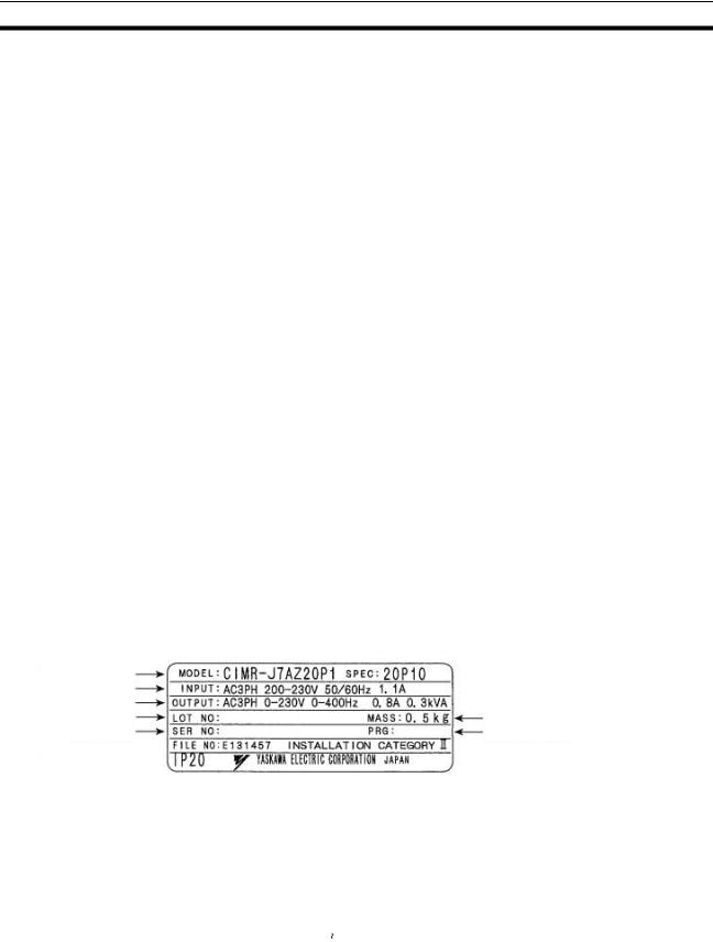
Проверка паспортной таблички
|
Модель регулятора частоты |
|
|
Входные характеристики |
|
|
Выходные характеристики |
Масса регулятора |
|
Номер партии |
|
|
Серийный номер |
Номер ПО |
Модель
преобразователя
C I M R — J 7 A Z 2 0 P 1
|
Регулятор |
Максимальная мощность |
||||||||||||||||||||||
|
частоты |
|||||||||||||||||||||||
|
применяемого электродвигателя |
|||||||||||||||||||||||
|
Серия J7 |
|||||||||||||||||||||||
|
0P1: 0,1 кВт |
|||||||||||||||||||||||
|
4P0: 4,0 кВт |
] |
||||||||||||||||||||||
|
A: С цифровой панелью управления |
«Р» соответствует |
||||||||||||||||||||||
|
(с потенциометром) |
[ десятичной запятой |
||||||||||||||||||||||
|
Z: Европейский стандарт |
Класс напряжения |
||||||||||||||||||||||
|
характеристики |
В: Вход: 1-фазное, 200 В~ |
||||||||||||||||||||||
|
2: Вход: 3-фазное, 200 В~ |
|||||||||||||||||||||||
|
4: Вход: 3-фазное, 400 В~ |
VIII

Максимальная мощность применяемого электродвигателя
|
0P1 |
0,1 |
(0,1) кВт |
|
|
0P2 |
0,25/0,37 (0,2) кВт |
||
|
0P4 |
0,55 (0,4) |
кВт |
|
|
0P7 |
1,1 |
(0,75) |
кВт |
|
1P5 |
1,5 |
(1,5) кВт |
|
|
2P2 |
2,2 |
(2,2) кВт |
|
|
4P0 |
4,0 |
(4,0) кВт |
|
Примечание: |
Цифры в скобках указывают на мощность двигателей, которые |
|
|
используются за пределами Японии. |
||
|
Класс напряжения |
||
|
2 |
3-фазное напряжение 200 В~ (200 В класс) |
|
|
B |
1-фазное напряжение 200 В~ (200 В класс) |
|
|
4 |
3-фазное напряжение 400 В~ (400 В класс) |
|
|
Проверка на отсутствие |
Визуально проверьте регулятор на наличие каких-либо царапин или |
|
|
повреждений |
иных повреждений, возникших в процессе доставки |
Содержание данного Руководства
|
Данное Руководство разделено на главы, описание которых приводится |
|
|
вследующей таблице. Информация представлена по областям применения |
|
|
для более эффективного использования настоящего руководства. |
|
|
Глава |
Содержание |
|
Глава 1 Общие сведения |
Описывает свойства и номенклатуру |
|
Глава 2 Конструкция регулятора |
В этой главе представлены габаритные и монтажные размеры, способы |
|
установки, монтажа, информация о конструкции периферийного |
|
|
оборудования и правила подбора периферийного оборудования. |
|
|
Глава 3 Подготовка к работе |
Описывается номенклатура и действия с цифровой панелью управления |
|
и контроль |
для работы и контроля регулятора. |
|
Глава 4 Пробный пуск |
В главе описывается метод управления двигателем через изменение опорной |
|
частоты с помощью регулятора на передней панели регулятора частоты. |
|
|
Этотметод может быть использован в качестве испытания для системы. |
|
|
Глава 5 Базовые операции |
В данной главе для пользователей, не имеющих опыт работы с регуляторами |
|
частоты, описываются базовые функции управления регулятором. Понимание |
|
|
данных функций является основой для управления двигателем с помощью |
|
|
описываемых в Руководстве регуляторов. |
|
|
Глава 6 Расширенное использование |
В этой главе дается обзор всех функций, доступных в регуляторе. Данные |
|
функции, такие, например, как способность к реагированию |
|
|
(характеристики момента), функция компенсации скольжения, функция |
|
|
обнаружения повышенного момента, функция ПИД управления и другие, |
|
|
позволяют применять регулятор частоты для более сложных задач, |
|
|
улучшить управление двигателем при использовании регулятора. |
|
|
Глава 7 Коммуникации |
В главе содержатся описания для блока связи RS-422/485 и функций связи |
|
регулятора по RS-422/485 интерфейсу, включая методы соединения. |
|
|
Глава 8 Поиск и устранение |
В данной главе представлена информация по обслуживанию, контролю |
|
неисправностей |
и поиску неисправностей регулятора |
|
Глава 9 Технические характеристики |
Представлены как характеристики регулятора частоты, так и габаритные |
|
размеры и характеристики периферийных устройств |
|
|
Глава 10 Параметры пользователя |
В главе перечислены параметры, доступные для настройки |
|
пользователям, уже имеющим опыт работы с регуляторами частоты. |
|
|
Параметры перечислены с указанием на страницу с их описанием. |
|
|
Глава 11 Указания по применению |
В главе дана информация по использованию регулятора для двигателя |
|
регулятора для двигателя |
Внимательно прочтите данное руководство
Перед подключением и использованием регулятора частоты следует внимательно прочитать настоящее руководство. С вопросами и комментариями обращайтесь, пожалуйста, к Вашему региональному представителю OMRON-YASKAWA.
IX

Гарантия и ограничение ответственности
ГАРАНТИЯ
OMRON-YASKAWA предоставляет эксклюзивную гарантию на качество материалов и изготовление изделия сроком в один год (если не указано иного срока), начиная с даты продажи компанией OMRON-YASKAWA.
OMRON-YASKAWA НЕ ДАЕТ НИКАКОЙ ГАРАНТИИ ИЛИ ПОДТВЕРЖДЕНИЯ, НИ ЧЕТКО ВЫРАЖЕННЫХ, НИ СКРЫТНЫХ СОГЛАСИЙ В ОТНОШЕНИИ НЕСОБЛЮДЕНИЯ ПРАВ ТРЕТЬИХ ЛИЦ, КОММЕРЦИИ ИЛИ
ПРИГОДНОСТИ ИЗДЕЛИЙ ДЛЯ ОПРЕДЕЛЕННОГО ЛЮБОЙ ПОКУПАТЕЛЬ ИЛИ ПОЛЬЗОВАТЕЛЬ УВЕДОМЛЕН, ЧТО ПОКУПАТЕЛЬ ИЛИ ПОЛЬЗОВАТЕЛЬ САМОСТОЯТЕЛЬНО РЕШАЕТ, ПРИГОДНЫ ЛИ СООТВЕТСТВУЮЩИЕ ИЗДЕЛИЯ ДЛЯ ПРЕДУСМОТРЕННОГО ПРИМЕНЕНИЯ. OMRON НЕ ПРИЗНАЕТ НИКАКИХ ДРУГИХ ГАРАНТИЙ, ЯВНО ВЫРАЖЕННЫХ ИЛИ СКРЫТЫХ.
ОГРАНИЧЕНИЕ ОТВЕТСТВЕННОСТИ
OMRON-YASKAWA НЕ НЕСЕТ ОТВЕТСТВЕННОСТЬ ЗА СПЕЦИФИЧЕСКИЙ, КОСВЕННЫЙ УЩЕРБ ИЛИ ПОТЕРЮ ПРИБЫЛЕЙ, КОММЕРЧЕСКИЕ УБЫТКИ ЛЮБОГО РОДА, СВЯЗАННЫЕ С ИЗДЕЛИЯМИ, В РАВНОЙ СТЕПЕНИ СЛУЖИТ ЛИ БАЗОЙ ПРЕДЪЯВЛЕНИЯ ИСКА ДОГОВОР,
OMRON-YASKAWA не несет ни в коем случае ответственность за любые действия, которые приводят к превышению соответствующей цены изделия, на которую распространяется иск.
OMRON-YASKAWA НЕ НЕСЕТ НИ В КОЕМ СЛУЧАЕ ОТВЕТСТВЕННОСТЬ ЗА ГАРАНТИЮ, РЕМОНТ ИЛИ ДРУГИЕ ПРЕТЕНЗИИ В ОТНОШЕНИИ ИЗДЕЛИЙ, ПОКА ПРОВЕДЕННОЕ OMRON-YASKAWA ИССЛЕДОВАНИЕ
НЕ ПОДТВЕРДИТ, ЧТО С ИЗДЕЛИЯМИ ОБРАЩАЛИСЬ ПРАВИЛЬНО, БЫЛО ОБЕСПЕЧЕНО НАДЛЕЖАЩЕЕ ХРАНЕНИЕ И МОНТАЖ, РЕГУЛЯРНО ПРОВОДИЛОСЬ ТЕХОБСЛУЖИВАНИЕ, А ТАКЖЕ ОНИ НЕ БЫЛИ ЗАГРЯЗНЕНЫ, ПРИМЕНЯЛИСЬ ПО НАЗНАЧЕНИЮ, НЕ БЫЛО ПРЕДПРИНЯТО НИКАКИХ ИЗМЕНЕНИЙ ИЗДЕЛИЯ И НЕ ПРОИЗВОДИЛСЯ РЕМОНТ.
Указания по использованию
ПРИГОДНОСТЬ
OMRON-YASKAWA не несет ответственность за несоблюдение правильного использования изделий в составе машин, установок, действующих норм, стандартов, кодов и т.д.
По желанию заказчиков OMRON предоставляет требующиеся документы третьих лиц по сертифицированию, где указаны номинальные значения и ограничения в применении соответствующих изделий. Одной этой информации недостаточно для полного определения пригодности изделий в комбинации с конечными продуктами, машинами, системами или другими областями применения.
Далее приводятся некоторые примеры применения, на которые следует обратить особое внимание. Представленный перечень нельзя рассматривать как комплектный перечень, а также, что приведенные примеры применения подходят для изделий.
•Применение на открытом воздухе, использование с потенциально возможным химическим загрязнением или электрической интерференцией или при наличии условий, которые не описаны в приведенном руководстве.
•Системы управления ядерной техникой, системы сгорания, железнодорожный транспорт, авиационная промышленность, медицинские приборы, игровые автоматы, оборудование для обеспечения безопасности
идругие системы, устройства или аппаратура, которые подлежат соблюдению законодательных предписаний
иотраслевых инструкций.
•Системы, машины и устройства, которые могутпредставлять опасность для жизни и наносить материальный ущерб. Ознакомьтесь, пожалуйста, со всеми ограничениями в отношении применения этих изделий и соблюдайте их.
НИКОГДА НЕ ИСПОЛЬЗУЙТЕ ИЗДЕЛИЯ В СЛУЧАЯХ, КОТОРЫЕ МОГУТ ПРЕДСТАВЛЯТЬ ОПАСНОСТЬ ДЛЯ ЖИЗНИ ИЛИ СОБСТВЕННОСТИ, НЕ УБЕДИВШИСЬ, ЧТО ОБЩАЯ СИСТЕМА РАЗРАБАТЫВАЕТСЯ С УЧЕТОМ ВОЗМОЖНОГО РИСКА, И ЧТО ИЗДЕЛИЯ OMRON-YASKAWA В ОТНОШЕНИИ ПРИМЕНЕНИЯ В ОБЩЕМ УСТРОЙСТВЕ ИЛИ ОБЩЕЙ СИСТЕМЕ СООТВЕТСТВЕННО ПРАВИЛЬНО РАССЧИТЫВАЮТСЯ И УСТАНАВЛИВАЮТСЯ.
ПРОГРАММИРУЕМЫЕ ИЗДЕЛИЯ
Компания ИЗДЕЛИЯ OMRON-YASKAWA не несет ответственности за программы пользователя, создаваемые для программируемых изделий, и за какие-либо последствия, возникшие в результате их применения.
X
![]()
Отказ от ответственности
ИЗМЕНЕНИЕ ТЕХНИЧЕСКИХ ХАРАКТЕРИСТИК
Технические характеристики изделия и принадлежностей могут быть изменены в любое время при совершенствовании изделия и по другим причинам.
В случае изменения характеристик или функций изделия, а также при внесении значительных конструктивных изменений, модельный номер обычно меняется. И все же некоторые характеристики могут быть изменены без предварительного уведомления. По требованию заказчика, возможно использование специальной кодировки моделей для конкретных применений. Для подтверждения фактических технических характеристик приобретенного изделия обращайтесь в службу технической поддержки OMRON-YASKAWA.
ГАБАРИТНЫЕ РАЗМЕРЫ И ВЕС
В настоящем документе приведены номинальные значения габаритов и весов, и их нельзя использовать в конструкторской документации, даже если приведены значения допусков.
ЭКСПЛУАТАЦИОННЫЕ ХАРАКТЕРИСТИКИ
Приведенные в настоящем документе эксплуатационные характеристики служат в качестве ориентира для пользователей при определении пригодности изделий для задач пользователей и не являются предметом гарантийного обязательства. Это могут быть результаты испытаний, проведенных компанией OMRON-YASKAWA, поэтому пользователь должен соотносить их с фактическими требованиями реализуемой системы. Фактические эксплуатационные характеристики являются предметом «Гарантийных обязательств» и «Ограничения ответственности» компании OMRON-YASKAWA.
ОШИБКИ И ОПЕЧАТКИ
Информация, содержащаяся в настоящем руководстве, была тщательно проверена и, вероятнее всего, является точной; тем не менее, компания OMRON-YASKAWA не несет ответственности за допущенные типографские ошибки или опечатки.
XI

XII
Содержание
ГЛАВА 1
Обзор . . . . . . . . . . . . . . . . . . . . . . . . . . . . . . . . . . . . . . . . 1
1-1 Назначение. . . . . . . . . . . . . . . . . . . . . . . . . . . . . . . . . . . . . . . . . . . . . . . . . . . . . 2 1-2 Название частей и обозначения . . . . . . . . . . . . . . . . . . . . . . . . . . . . . . . . . . . . 3
ГЛАВА 2
Конструкция. . . . . . . . . . . . . . . . . . . . . . . . . . . . . . . . . . 5
2-1 Установка . . . . . . . . . . . . . . . . . . . . . . . . . . . . . . . . . . . . . . . . . . . . . . . . . . . . . . 6 2-2 Подключение . . . . . . . . . . . . . . . . . . . . . . . . . . . . . . . . . . . . . . . . . . . . . . . . . . 10
ГЛАВА 3 Подготовка к работе и контроль . . . . . . . . . . . . . . . 33
3-1 Название частей и обозначения . . . . . . . . . . . . . . . . . . . . . . . . . . . . . . . . . . . 34 3-2 Пример работы. . . . . . . . . . . . . . . . . . . . . . . . . . . . . . . . . . . . . . . . . . . . . . . . . 35
ГЛАВА 4
Пробный запуск. . . . . . . . . . . . . . . . . . . . . . . . . . . . . . 41
4-1 Процедура пробного запуска . . . . . . . . . . . . . . . . . . . . . . . . . . . . . . . . . . . . . 43 4-2 Примеры пробного пуска . . . . . . . . . . . . . . . . . . . . . . . . . . . . . . . . . . . . . . . . 45
ГЛАВА 5
Основные функции. . . . . . . . . . . . . . . . . . . . . . . . . . . 49
5-1 Первоначальные уставки . . . . . . . . . . . . . . . . . . . . . . . . . . . . . . . . . . . . . . . . 50 5-2 Регулирование V/f . . . . . . . . . . . . . . . . . . . . . . . . . . . . . . . . . . . . . . . . . . . . . . 51 5-3 Установка режима локальное/дистанционное управление. . . . . . . . . . . . . 53 5-4 Выбор рабочей команды. . . . . . . . . . . . . . . . . . . . . . . . . . . . . . . . . . . . . . . . . 54 5-5 Выбор заданной частоты. . . . . . . . . . . . . . . . . . . . . . . . . . . . . . . . . . . . . . . . . 55 5-6 Установка времени разгона/торможения . . . . . . . . . . . . . . . . . . . . . . . . . . . 60 5-7 Выбор запрета на вращение в обратном направлении. . . . . . . . . . . . . . . . . 62 5-8 Выбор режима прекращения работы. . . . . . . . . . . . . . . . . . . . . . . . . . . . . . . 62 5-9 Многофункциональный вход/выход . . . . . . . . . . . . . . . . . . . . . . . . . . . . . . . 63 5-10 Аналогового выход . . . . . . . . . . . . . . . . . . . . . . . . . . . . . . . . . . . . . . . . . . . . . 68
ГЛАВА 6
Расширенные функции . . . . . . . . . . . . . . . . . . . . . . . 69
6-1 Задание несущей частоты. . . . . . . . . . . . . . . . . . . . . . . . . . . . . . . . . . . . . . . . 70 6-2 Функция торможения постоянным током. . . . . . . . . . . . . . . . . . . . . . . . . . . 72 6-3 Функция предотвращения опрокидывания. . . . . . . . . . . . . . . . . . . . . . . . . . 73 6-4 Функция обнаружения повышенного момента . . . . . . . . . . . . . . . . . . . . . . 76 6-5 Функция компенсации момента. . . . . . . . . . . . . . . . . . . . . . . . . . . . . . . . . . . 77 6-6 Функция компенсации скольжения. . . . . . . . . . . . . . . . . . . . . . . . . . . . . . . . 78 6-7 Прочие функции . . . . . . . . . . . . . . . . . . . . . . . . . . . . . . . . . . . . . . . . . . . . . . . 79
XIII
Содержание
ГЛАВА 7
Обмен данными. . . . . . . . . . . . . . . . . . . . . . . . . . . . . . 89
7-1 Устройство связи по RS-422/485 интерфейсу. . . . . . . . . . . . . . . . . . . . . . . . 90 7-2 Настройка регулятора частоты. . . . . . . . . . . . . . . . . . . . . . . . . . . . . . . . . . . . 93 7-3 Формат сообщений обмена на BASIC . . . . . . . . . . . . . . . . . . . . . . . . . . . . . . 98 7-4 Сообщение DSR и ответ . . . . . . . . . . . . . . . . . . . . . . . . . . . . . . . . . . . . . . . . 101 7-5 Команда ВВОД (Enter) . . . . . . . . . . . . . . . . . . . . . . . . . . . . . . . . . . . . . . . . . 108 7-6 Настройка данных обмена . . . . . . . . . . . . . . . . . . . . . . . . . . . . . . . . . . . . . . 109 7-7 Назначение номеров регистров в деталях. . . . . . . . . . . . . . . . . . . . . . . . . . 111 7-8 Коды ошибок обмена . . . . . . . . . . . . . . . . . . . . . . . . . . . . . . . . . . . . . . . . . . 115 7-9 Тест самодиагностики. . . . . . . . . . . . . . . . . . . . . . . . . . . . . . . . . . . . . . . . . . 116
ГЛАВА 8 Неисправности и техническое
обслуживание. . . . . . . . . . . . . . . . . . . . . . . . . . . . . . . 117
8-1 Функции защиты и диагностики . . . . . . . . . . . . . . . . . . . . . . . . . . . . . . . . . 118 8-2 Поиск и устранение неисправностей. . . . . . . . . . . . . . . . . . . . . . . . . . . . . . 123 8-3 Техническое обслуживание и проверка . . . . . . . . . . . . . . . . . . . . . . . . . . . 128
ГЛАВА 9
Характеристики. . . . . . . . . . . . . . . . . . . . . . . . . . . . . 131
9-1 Характеристики регулятора частоты. . . . . . . . . . . . . . . . . . . . . . . . . . . . . . 132 9-2 Характеристики дополнительных устройств . . . . . . . . . . . . . . . . . . . . . . . 135 9-3 Технические характеристики дополнительных устройств . . . . . . . . . . . . 142
ГЛАВА 10
Список параметров. . . . . . . . . . . . . . . . . . . . . . . . . . 145
ГЛАВА 11 Использование регулятора частоты
с двигателем . . . . . . . . . . . . . . . . . . . . . . . . . . . . . . . . 159
XIV
ГЛАВА 1 Обзор
|
1-1 |
Назначение . . . . . . . . . . . . . . . . . . . . . . . . . . . . . . . . . . . . . . . . . . . . . . . . . . . |
2 |
|
1-2 |
Название частей и обозначения . . . . . . . . . . . . . . . . . . . . . . . . . . . . . . . . . . |
3 |
1

Назначение Глава 1-1
1-1 Назначение
Компактный простой регулятор частоты серии VARISPEED J7 значительно легче в использовании, чем любые другие традиционные модели регуляторов. VARISPEED J7 отвечает требованиям директив ЕС и стандарта UL/cUL для повсеместного использования.
Модели регулятора VARISPEED J7
Данная серия представлена следующими трехфазными и однофазными моделями класса 200 В и трехфазными моделями класса 400 В переменного тока J7AZ.
|
Номинальное |
Защитная конструкция |
Максимальнаямощность |
Модель |
|
|
напряжение |
двигателя, кВт |
|||
|
Трехфазное, 200В |
Модели для настенного |
0,1 |
CIMR-J7AZ20P1 |
|
|
переменного тока |
монтажа (соответствует |
|||
|
0,25 |
CIMR-J7AZ20P2 |
|||
|
IP20) |
||||
|
0,55 |
CIMR-J7AZ20P4 |
|||
|
1,1 |
CIMR-J7AZ20P7 |
|||
|
1,5 |
CIMR-J7AZ21P5 |
|||
|
2,2 |
CIMR-J7AZ22P2 |
|||
|
4,0 |
CIMR-J7AZ24P0 |
|||
|
Однофазное, 200В |
Модели для настенного |
0,1 |
CIMR-J7AZB0P1 |
|
|
переменного тока |
монтажа (соответствует |
|||
|
0,25 |
CIMR-J7AZB0P2 |
|||
|
IP20) |
||||
|
0,55 |
CIMR-J7AZB0P4 |
|||
|
1,1 |
CIMR-J7AZB0P7 |
|||
|
1,5 |
CIMR-J7AZB1P5 |
|||
|
Трехфазное, 400В |
Модели для настенного |
0,37 |
CIMR-J7AZ40P2 |
|
|
переменного тока |
монтажа (соответствует |
|||
|
0,55 |
CIMR-J7AZ40P4 |
|||
|
IP20) |
||||
|
1,1 |
CIMR-J7AZ40P7 |
|||
|
1,5 |
CIMR-J7AZ41P5 |
|||
|
2,2 |
CIMR-J7AZ42P2 |
|||
|
4,0 |
CIMR-J7AZ44P0 |
Примечание: Для регуляторов частоты серии J7 невозможно подключение тормозного резистора или тормозного блока. Выбирайте модель регулятора другой серии для задач, где требуется управление тормозом.
Международные стандарты (Директивы ЕС и стандарты UL/cUL)
Гибкие Простые в использовании функции
Регулятор частоты серии J7 соответствует требованиям директив ЕС и стандарта UL/cUL для повсеместного использования.
|
Классификация |
Применимый стандарт |
||
|
Директивы ЕС |
Директива ЭМС |
EN50081-2 и EN5008-2 |
|
|
Директива для |
prEN50178 |
||
|
низковольтных устройств |
|||
|
UL/cUL |
UL508C |
•Обладает функциями и эксплуатационными качествами, обеспечиваемыми стандартнымиприводами серииJ7AZ.
•Легко инициализировать и управлять с помощью потенциометра настройки частоты FREQ на цифровой панели управления.
•Простота техобслуживания. Охлаждающий вентилятор легко заменяется. Срок службы охлаждающего вентилятора можно продлить, если включать его только во время работы Регулятора частоты.
|
Подавление |
Подключается к реакторам постоянного тока, таким образом подавляя |
|
гармоник |
гармоники более эффективно, чем стандартные реакторы переменного тока. |
|
Дальнейшее подавление гармоник возможно, если использовать |
|
|
совместно реакторы постоянного и переменного тока. |
2

|
Название частей и обозначения |
Глава 1-2 |
1-2 Название частей и обозначения
Панель
Дисплей данных
Клавиша выбора дисплея
Переключение между типами дисплеев.
Клавиша ввода
Ввод данных после установки констант.
После выбора констант в режиме PRGM данные отражаются на дисплее.
Клавиша увеличения
Увеличение заданного значения или пункта меню.
Клавиша уменьшения
Уменьшение заданного значения или пункта меню.
Клавиша
останова/сброса
Нажмите для остановки двигателя. При возникновении ошибки, перезапустите регулятор.
Цифровая панель управления
Функциональные
индикаторы
Индикация выбранной функции (перечисление функций приводится ниже). Параметры функции отображаются на дисплее.
Клавиша управления
Запуск работы регулятора. Индикатор RUN светится.
Индикатор тревоги
Индикатор работы
Регулятор частоты
Установка рабочей частоты и ее уровня.
Примечание: 1. Передняя крышка выполняет роль крышки для клеммных колодок. Блок цифровой панели управления снимать нельзя.
2.Вместо монтажных отверстий каждая из следующих моделей имеет U-образные вырезы, расположенные диагонально.
CIMR-J7AZ20P1 (0,1 кВт), CIMR-J7AZ20P2 (0,25 кВт), CIMR-J7AZ20P4 (0,55 кВт), и CIMR-J7AZ20P7 (1,1 кВт) CIMR-J7AZB0P1 (0,1 кВт), CIMR-J7AZB0P2 (0,25 кВт), и CIMR-J7AZ20P7 (0,55 кВт)
3

|
Название частей и обозначения |
Глава 1-2 |
||
|
Цифровая панель управления |
|||
|
Индикаторы |
|||
|
Дисплей |
(индикаторы |
||
|
уставок/ |
|||
|
данных |
|||
|
контролируемых |
|||
|
величин) |
|||
|
Клавиши |
Потенциометр |
||
|
настройки |
|||
|
частоты (FREQ) |
|||
|
Внешний вид |
Название |
Назначение |
|
|
Дисплей данных |
Отображает соответствующие данные, такие как заданная частота, |
||
|
выходная частота и установленные значения параметров. |
|||
|
Потенциометр |
Устанавливает заданную частоту в диапазоне от 0 Гц до максимальной |
||
|
настройкичастоты |
частоты. |
||
|
(FREQ) |
|||
|
Индикатор FREF |
Заданную частоту можно контролировать или устанавливать пока горит |
||
|
этот индикатор. |
|||
|
Индикатор FOUT |
Пока горит этот индикатор, можно контролировать выходную частоту |
||
|
регулятора. |
|||
|
Индикатор IOUT |
Пока горит этот индикатор, можно контролировать выходной ток |
||
|
регулятора. |
|||
|
Индикатор MNTR |
Пока горит этот индикатор, можно контролировать значения, |
||
|
установленные параметрами с U01 по U10. |
|||
|
Индикатор F/R |
Пока горит этот индикатор, можно выбирать направление вращения, |
||
|
когда регулятор управляется с помощью клавиши RUN. |
|||
|
Индикатор LO/RE |
Пока горит этот индикатор, можно выбрать способ управления |
||
|
регулятором с помощью цифровой панели управления или |
|||
|
в соответствии с установленными параметрами. |
|||
|
Примечание: Это состояние индикатора можно наблюдать только |
|||
|
во время работы регулятора. Любой ввод команды RUN |
|||
|
игнорируется, когда горит этот индикатор. |
|||
|
Индикатор PRGM |
Пока горит этот индикатор, можно устанавливать или контролировать |
||
|
параметры от n01 до n79. |
|||
|
Примечание: Покарегуляторработает, параметрыможнотольконаблюдать |
|||
|
и лишь некоторые из них можно изменять. Любой ввод |
|||
|
команды RUN игнорируется, когда горит этот индикатор. |
|||
|
Клавиша режима |
Последовательный переключает индикаторы уставок и контролируемых |
||
|
параметров. |
|||
|
Можно отменить устанавливаемый параметр, если нажать эту клавишу |
|||
|
до ввода уставки. |
|||
|
Клавиша |
Увеличивает номер функции, номер параметра и заданные значения |
||
|
увеличения |
параметров. |
||
|
Клавиша |
Уменьшает номер функции, номер параметра и заданные значения |
||
|
уменьшения |
параметров. |
||
|
Клавиша ввода |
Осуществляет ввод номера функции, номера параметра и значений |
||
|
внутренних данных после того, как они были установлены или изменены. |
|||
|
Клавиша RUN |
Запускает регулятор, когда J7AZ управляется с помощью цифровой |
||
|
панели управления. |
|||
|
Клавиша |
Останавливает регулятор, если параметр n06 (для блокировки клавиши |
||
|
STOP/RESET |
STOP) равен 0. Также работает как клавиша сброса, в случае |
||
|
возникновения ошибки. (См. примечание) |
Примечание: Из соображений безопасности, сброс не будет осуществлен пока выполняется работа в режиме RUN (вперед или назад). Подождите пока режим RUN не отключится, после этого перезапустите регулятор.
4
|
ГЛАВА 2 |
|||
|
Конструкция |
|||
|
2-1 |
Установка . . . . . . . . . . . . . . . . . . . . . . . . . . . . . . . . . . . . . . . . . . . . . . . . . . . . |
6 |
|
|
2-1-1 |
Габариты . . . . . . . . . . . . . . . . . . . . . . . . . . . . . . . . . . . . . . . . . . . . . |
6 |
|
|
2-1-2 |
Условия установки . . . . . . . . . . . . . . . . . . . . . . . . . . . . . . . . . . . . . |
8 |
|
|
2-2 |
Подключение . . . . . . . . . . . . . . . . . . . . . . . . . . . . . . . . . . . . . . . . . . . . . . . . . |
10 |
|
|
2-2-1 Снятие и установка крышек. . . . . . . . . . . . . . . . . . . . . . . . . . . . . . |
11 |
||
|
2-2-2 |
Блок выводов . . . . . . . . . . . . . . . . . . . . . . . . . . . . . . . . . . . . . . . . . . |
12 |
|
|
2-2-3 |
Стандартное подключение . . . . . . . . . . . . . . . . . . . . . . . . . . . . . . . |
16 |
|
|
2-2-4 |
Электромонтаж цепей питания . . . . . . . . . . . . . . . . . . . . . . . . . . . |
17 |
|
|
2-2-5 Электромонтаж выводов схемы управления . . . . . . . . . . . . . . . . |
27 |
||
|
2-2-6 |
Соответствие Директивам ЕС . . . . . . . . . . . . . . . . . . . . . . . . . . . . |
29 |
5

2-1 Установка
2-1-1 Габариты
Модели CIMR-J7AZ20P1 — CIMR-J7AZ20P7 (0,1 – 0,75 кВт) с трехфазным входным напряжением 200 В
переменного тока
Модели CIMR-J7AZB0P1 — CIMR-J7AZB0P4 (0,1 – 0,4 кВт) с однофазным входным напряжением 200 В переменного тока
D1
68
|
Номинальное |
Модель CIMR-J7AZ- |
Размеры (мм) |
Вес(кг) |
|||||
|
напряжение |
||||||||
|
D |
D1 |
t |
||||||
|
Трехфазное, 200 В |
20P1 |
70 |
10 |
3 |
Приблиз. 0,5 |
|||
|
переменного тока |
||||||||
|
20P2 |
70 |
10 |
3 |
Приблиз. 0,5 |
||||
|
20P4 |
102 |
42 |
5 |
Приблиз. 0,8 |
||||
|
20P7 |
122 |
62 |
5 |
Приблиз. 0,9 |
||||
|
Однофазное, 200 В |
B0P1 |
70 |
10 |
3 |
Приблиз. 0,5 |
|||
|
переменного тока |
||||||||
|
B0P2 |
70 |
10 |
3 |
Приблиз. 0,5 |
||||
|
B0P4 |
112 |
42 |
5 |
Приблиз. 0,9 |
6
![]()
Модели CIMR-J7AZ21P5 — CIMR-J7AZ22P2 (1,5 – 2,2 кВт) с трехфазным входным напряжением 200 В переменного тока
Модели CIMR-J7AZB0P7 — CIMR-J7AZB1P5 (0,75 – 1,5 кВт) с однофазным входным напряжением 200 В
переменного тока
Модели CIMR-J7AZ40P2 — CIMR-J7AZ42P2 (0,2 – 2,2 кВт) с трехфазным входным напряжением 400 В переменного тока
Два отверстия, диам. 5
|
5 |
5 |
||||||||||||||||
|
D1 |
|||||||||||||||||
|
6 |
96 |
8,5 |
|||||||||||||||
|
D |
|||||||||||||||||
|
108 |
|||||||||||||||||
|
Номинальное |
Модель CIMR-J7AZ- |
Размеры (мм) |
Вес(кг) |
||||||||||||||
|
напряжение |
|||||||||||||||||
|
D |
D1 |
||||||||||||||||
|
Трехфазное, 200 В |
21P5 |
129 |
64 |
Приблиз. 1,3 |
|||||||||||||
|
переменного тока |
|||||||||||||||||
|
22P5 |
154 |
64 |
Приблиз. 1,5 |
||||||||||||||
|
Однофазное, 200 В |
B0P7 |
129 |
64 |
Приблиз. 1,5 |
|||||||||||||
|
переменного тока |
|||||||||||||||||
|
B1P5 |
154 |
64 |
Приблиз. 1,5 |
||||||||||||||
|
Трехфазное, 400 В |
40P2 |
81 |
16 |
Приблиз. 1,0 |
|||||||||||||
|
переменного тока |
|||||||||||||||||
|
40P4 |
99 |
34 |
Приблиз. 1,1 |
||||||||||||||
|
40P7 |
129 |
64 |
Приблиз. 1,5 |
||||||||||||||
|
41P5 |
154 |
64 |
Приблиз. 1,5 |
||||||||||||||
|
42P2 |
154 |
64 |
Приблиз. 1,5 |
7

Модели CIMR-J7AZ24P0 (4,0 кВт) с трехфазным входным напряжением 200 В переменного тока Модели CIMR-J7AZ44P0 (4,0 кВт) с трехфазным входным напряжением 400 В переменного тока
Два отверстия, диам. 5
|
5 |
5 |
||||||||||||
|
6 |
128 |
8,5 |
D |
D1 |
|||||||||
|
140 |
|||||||||||||
|
Номинальное |
Модель CIMR-J7AZ- |
Размеры (мм) |
Вес(кг) |
||||||||||
|
напряжение |
|||||||||||||
|
D |
D1 |
||||||||||||
|
Трехфазное, 200 В |
24P0 |
161 |
71 |
Приблиз. 2,1 |
|||||||||
|
переменного тока |
|||||||||||||
|
Трехфазное, 400 В |
44P0 |
161 |
71 |
Приблиз. 2,1 |
|||||||||
|
переменного тока |
|||||||||||||
|
2-1-2 |
Условия установки |
||||||||||||
|
! |
ОСТОРОЖНО |
Обеспечьте |
соответствующее |
устройство |
останова на машину для |
||||||||
|
соблюдения безопасности. (Тормозное устройство не является устройством |
|||||||||||||
|
безопасного останова). В противном случае можно нанести повреждение |
|||||||||||||
|
оборудованию. |
|||||||||||||
|
! |
ОСТОРОЖНО |
Обеспечьте |
наличие |
внешнего устройства аварийного останова, |
|||||||||
|
позволяющего немедленную остановку работы оборудования и прерывание |
|||||||||||||
подачи питания. В противном случае возможны повреждения.
|
! |
ПРЕДУПРЕЖДЕНИЕ |
Регулятор должен быть установлен в правильном направлении и обеспечены |
|
|
все указанные зазоры между регулятором и панелью управления или |
|||
|
другими устройствами. В противном случае может возникнуть возгорание или |
|||
|
неисправность оборудования. |
|||
|
! |
ПРЕДУПРЕЖДЕНИЕ |
Не позволяйте попадание посторонних предметов внутрь регулятора. |
|
|
Это может вызвать возгорание или неисправность оборудования. |
|||
|
! |
ПРЕДУПРЕЖДЕНИЕ |
Обеспечьте защиту регулятора от недопустимых нагрузок. Это может |
|
|
повредить или привести в неисправность изделие. |
|||
8

Установка Глава 2-1
Направление установки и размеры
Установка регулятора возможна в местах, где соблюдаются следующие условия.
• Температура окружающей среды во время работы (при монтаже на панели): от –10°C до 50°C
• Влажность: не более 95 % (без конденсации)
|
Место установки регулятора должно быть чистым, без масляного тумана |
|
|
и пыли. Или же установите его в целиком закрытой панели, которая |
|
|
полностью защищена от проникновения летающей пыли. |
|
|
При установкеили эксплуатации преобразователя всегда принимайтеособые |
|
|
меры предосторожности, чтобы металлический порошок, масло, вода или |
|
|
другие посторонние вещества и предметы не попали в регулятор. |
|
|
Не устанавливайте регулятор на воспламеняющейся поверхности, |
|
|
например, на деревянной. |
|
|
Ориентация |
Устанавливайте регулятор на вертикальной поверхности так, чтобы |
|
буквы на паспортной пластинке были ориентированы вверх. |
|
|
Размещение |
При установке преобразователя всегда обеспечивайте следующие зазоры, |
|
чтобы дать возможность теплу нормально рассеиваться из регулятора. |
|
W = не менее 30 мм |
Не менее |
Воздух |
|
100 мм |
|
Регулятор |
Регулятор |
Регулятор |
Боковая |
|
частоты |
частоты |
частоты |
сторона |
|
W |
W |
W |
Не менее |
Воздух |
||
|
100 мм |
Контроль температуры окружающей среды
Для того, чтобы повысить надежность работы регулятора, его следует устанавливать в таком месте, где не бывает резких изменений температуры.
Если регулятор установлен в закрытом контейнере, например, в ящике, то используйте охлаждающий вентилятор или кондиционер воздуха для поддержания температуры внутри на уровне ниже 50°C. Срок службы встроенных электролитических конденсаторов регулятора продлевается, если поддерживать как можно более низкую температуру внутри.
Температура поверхности регулятора может превысить температуру окружающей среды приблизительно на 30°C. Непременно держите оборудование и провода как можно дальше от регулятора, если тепло сильно воздействует на них.
Защита регулятора от попадания внутрь посторонних предметов во время установки
Во время установки разместите крышку над регулятором, чтобы защитить его от металлического порошка, полученного при сверлении. После завершения установки всегда снимайте крышку с регулятора. Иначе ухудшится вентиляция, что вызовет перегрев регулятора.
9

2-2 Подключение
Любые работы по подключению должны производиться только при выключенном источнике питания. Иначе можно пострадать от электрошока.
Любые работы по подключению должны производиться только авторизованным персоналом. В противном случае можно пострадать от электрошока или вызвать возгорание.
|
! |
ОСТОРОЖНО |
Проверяйте правильность операций только после подключения цепи |
|
|
аварийного останова. В противном случае возможны повреждения. |
|||
Всегда подключайте клеммы земли к заземлителю с сопротивлением 100 Ом ! ОСТОРОЖНО или менее для класса 200 В или 10 Ом или менее для класса 400 В.
В противном случае возможно поражение электрическим током.
Установите внешние прерыватели и примите необходимые меры для ! ПРЕДУПРЕЖДЕНИЕ обеспечения безопасности против короткого замыкания во внешнем
соединении. В противном случае можно вызвать возгорание.
!ПРЕДУПРЕЖДЕНИЕ
!ПРЕДУПРЕЖДЕНИЕ
!ПРЕДУПРЕЖДЕНИЕ
!ПРЕДУПРЕЖДЕНИЕ
!ПРЕДУПРЕЖДЕНИЕ
Убедитесь, что номинальное входное напряжение регулятора соответствует напряжению источника питания переменного тока. Неправильный выбор источника питания может вызвать возгорание, повреждение или неисправность оборудования.
Подключайте тормозной резистор и тормозной блок в соответствии со спецификациями, указанными в руководстве пользователя. В противном случае можно вызвать возгорание.
Убедитесь в правильности и надежности выполненных соединений. Иначе можно вызвать повреждение или поломку изделия.
Убедитесь в том, что все винты на клеммном блоке надежно затянуты. В противном случае может произойти возгорание, повреждение или неисправность оборудования.
Не подключайте питание переменного тока к выходам U, V или W. Это может вызвать повреждение изделия или неисправность.
10

2-2-1 Снятие и установка крышек
Необходимо снять с регулятора переднюю крышку, дополнительную крышку, верхнюю защитную крышку и нижнюю защитную крышку, чтобы подключиться к блоку выводов. Следуйте приведенным ниже указаниям, чтобы снять все крышки с регулятора. Чтобы надеть крышки, следует выполнить все действия в обратном порядке.
Снятие передней крышки
• С помощью отвертки освободите крепежные винты передней крышки.
• Нажмите на левую и правую боковые стороны передней крышки в направлении, указанном стрелками 1, и поднимите нижнюю часть крышки в направлении, указанном стрелкой 2, чтобы снять переднюю крышку, как показано на рисунке ниже.
1 2
Снятие верхней и нижней защитных крышек и дополнительной крышки
Снятие верхней и нижней защитных крышек
• После того, как вы сняли переднюю крышку, потяните верхнюю и нижнюю защитные крышки в направлении, указанном стрелками 1.
Снятие дополнительной крышки
•После того, как вы сняли переднюю крышку, поднимите дополнительную крышку в направлении, показанном стрелкой 2, используя в качестве точки опоры позицию А.
1
Позиция А
2
1
11

2-2-2 Блок выводов
Перед подключением к блоку выводов обязательно снимите переднюю крышку, верхнюю и нижнюю защитные крышки.
Расположение блока выводов
Клемма
заземления
Входные клеммы цепи питания
|
Клеммы схемы |
|
|
управления |
|
|
Выходные клеммы для |
|
|
подключения двигателя |
Клемма заземления |
Организация выводов схемы управления
Организация выводов цепей питания
•CIMR-J7AZ20P1 – CIMR-J7AZ20P7 CIMR-J7AZB0P1 – CIMR-J7AZB0P4
•CIMR-J7AZ21P5 – CIMR-J7AZ24P0 CIMR-J7AZB0P7 – CIMR-J7AZB4P0 CIMR-J7AZ40P2 – CIMR-J7AZ44P0
Входные клеммы цепей питания Входные клеммы цепей питания (В верхней части передней панели) (В верхней части передней панели)
|
Выходные клеммы цепей питания |
Выходные клеммы цепей питания |
|
(В нижней части передней панели) |
(В нижней части передней панели) |
12

|
Подключение |
Глава 2-2 |
|||
|
Клеммы цепи питания |
||||
|
Обозначение |
Название |
Описание |
||
|
R/L1 |
Входные клеммы источника |
CIMR-J7AZ2_: Трехфазное напряжение от 200 до 230 В |
||
|
питания |
переменного тока |
|||
|
S/L2 |
CIMR-J7AZB_: Однофазное напряжение от 200 до 240 В |
|||
|
переменного тока |
||||
|
T/L3 |
||||
|
CIMR-J7AZ4_: Трехфазное напряжение от 380 до 460 В |
||||
|
переменного тока |
||||
|
Примечание: Подключите однофазный вход к выводам R/L1 и S/L2. |
||||
|
U/T1 |
Выходные клеммы для |
Выход трехфазного питания для управляемых двигателей. |
||
|
подключения двигателя |
CIMR-J7AZ2_: Трехфазное напряжение от 200 до 230 В |
|||
|
V/T2 |
||||
|
переменного тока |
||||
|
CIMR-J7AZB_: Трехфазное напряжение от 200 до 240 В |
||||
|
W/T3 |
||||
|
переменного тока |
||||
|
+1 |
Клеммы +1 и +2: |
Подключите реактор постоянного тока для подавления гармоник |
||
|
Выводы для подключения |
к выводам +1 и +2. |
|||
|
+2 |
реактора постоянного тока |
Когда привод запитывается от источника постоянного тока, |
||
|
+1 и –: |
подключите источник постоянного тока к клеммам +1 и –. |
–Входные клеммы источника (Клемма +1 является положительным выводом) питания постоянного тока
|
Клемма заземления |
Обязательно заземляйте клемму в соответствии со следующими |
|
условиями. |
|
|
CIMR-J7AZ2_: Заземление с сопротивлением 100 Ом или меньше. |
|
|
CIMR-J7AZB_: Заземление с сопротивлением 100 Ом или меньше. |
|
|
CIMR-J7AZ4_: Заземление с сопротивлением 10 Ом или меньше, |
|
|
и подключитесь к нейтрали источника питания для соответствия |
|
|
требованиям директивы ЕС. |
|
|
Примечание: Убедитесь в том, что клемма заземления |
|
|
непосредственно соединена с землей основания |
|
|
двигателя. |
Примечание: Максимальное выходное напряжение соответствует входному напряжению источника питания регулятора.
13

|
Подключение |
Глава 2-2 |
|||
|
Выводы схемы управления |
||||
|
Обозначение |
Название |
Назначение |
Уровень сигнала |
|
|
Вход |
S1 |
Вперед/Стоп |
Вперед, если включено. |
Оптроннаяпара |
|
Стоп, если выключено. |
8 мАпри24 Впостоянноготока |
|||
|
Примечание: NPN поумолчанию |
||||
|
S2 |
Многофункциональный |
Задается параметром n36 |
||
|
вход 1 (S2) |
(Обратно/Останов) |
дляданныхклемм. |
||
|
Соединяйтеих, |
||||
|
S3 |
Многофункциональный |
Задается параметром n37 |
||
|
обеспечиваяобщую |
||||
|
вход 2 (S3) |
(Сброс после сбоя) |
землю. Нетребуе- |
||
|
тсявнешних |
||||
|
S4 |
Многофункциональный |
Задается параметром n38 |
||
|
источниковпитания. |
||||
|
вход 3 (S4) |
(внешний сбой: нормально |
|||
|
Темнеменее, |
||||
|
разомкнутый) |
||||
|
дляподключения |
||||
|
S5 |
Многофункциональный |
Задается параметром n39 |
||
|
внешнегоисточника |
||||
|
вход 4 (S5) |
(опорная частота 1 |
питанияисоедине- |
||
|
многоступенчатой скорости) |
ниявыводовчерез |
|||
|
SC |
Общий ввода цикла |
Общий для S1 — S5 |
общуюположи- |
|
|
тельнуюлинию, |
||||
|
установитеSW7 на |
||||
|
PNP иубедитесь |
||||
|
втом, чтонапряже- |
||||
|
ниеисточника |
||||
|
питаниясоставляет |
||||
|
24 В= ±10 %. |
||||
|
FS |
Источник питания |
Источник питания постоянного |
20 мА при 12 В постоянного тока |
|
|
заданной частоты |
тока для заданной частоты |
|||
|
FR |
Вход заданной частоты |
Входная клемма для заданной |
От 0 до 10 В постоянного тока |
|
|
частоты |
(входное сопротивление: 20 кОм) |
|||
|
FC |
Общий заданной частоты |
Общий для |
||
|
заданной частоты |
||||
|
Выход |
MA |
Многофункциональный |
Задается параметром n40 |
Релейный выход |
|
контактныйвыход |
(во время вращения двигателя) |
макс. 1 А при 30 В постоянного |
||
|
(нормальноразомкнутый) |
тока |
|||
|
макс. 1 А при 250 В переменного |
||||
|
MB |
Общиймногофункционального |
|||
|
тока |
||||
|
контактноговыхода |
||||
|
(нормальнозамкнутый) |
||||
|
MC |
Общий |
Общий для MA и MB |
||
|
многофункционального |
||||
|
AM |
Выход аналогового |
Задается параметром n44 |
Макс. 2 мА напряжении от 0 до |
|
|
монитора |
(выходная частота) |
10 В постоянного тока. |
||
|
AC |
Общий выхода аналогового |
Общий для AM |
||
|
монитора |
||||
Примечание: 1. В зависимости от параметров установок, для многофункциональных входов и выходов могут быть выбраны различные функции.
2. Функции в круглых скобках являются установками по умолчанию.
Выбор метода введения входного сигнала
Переключатели SW7 и SW8, которые располагаются над выводами цепи управления, используются для выбора способа введения входных сигналов. Для того, чтобы использовать эти переключатели, снимите переднюю крышку и дополнительную крышку.
SW7 SW8
Клеммная
колодка
схемы
управления
14

|
Подключение |
Глава 2-2 |
|||||||
|
Выбор способа |
Используя SW7, можно выбрать вход NPN или PNP, как показано ниже. |
|||||||
|
введения входного |
||||||||
|
сигнала управления |
24 В |
|||||||
|
NPN |
SW7 |
|||||||
|
циклом |
||||||||
|
GND |
|||||
|
5 |
0,1 |
||||
|
S1 … 5 |
3,3 k |
||||
360
SC
GND
24 В
|
PNP |
|||||||||||||||
|
SW7 |
|||||||||||||||
|
GND |
|||||||||||||||
|
0,1 |
|||||||||||||||
|
S1 …55 |
|||||||||||||||
|
3,3 k |
|||||||||||||||
|
2424ВВ= |
|||||||||||||||
|
360 |
|||||||||||||||
|
(+10%) |
|||||||||||||||
|
постоянного |
|||||||||||||||
|
%) |
SC |
||||||||||||||
|
тока (+10 |
|||||||||||||||
|
GND |
Выбор способа введения заданной частоты
Используя SW8, можно выбрать потенциальный или токовый входной сигнал заданной частоты. Наряду с выбором способа введения заданной частоты необходимо установить параметры.
|
Способ введения |
Положение SW8 |
Выбор |
|
заданной частоты |
заданной частоты |
|
|
(параметр n03) |
||
|
Вход напряжения |
V (положение OFF) |
Установите значение 2 |
|
Вход тока |
I (положение ON) |
Установите значение 3 или 4 |
15

2-2-3 Стандартное подключение
Реактор
постоянного
тока
Помехозащитный
фильтр
Трехфазное, 200 В переменного тока Однофазное, 200 В переменного тока (см. примечание 1)
Трехфазное, 400 В переменного тока
|
Вперед/Стоп |
Многофункциональный |
|
|
контактный выход |
||
|
Многофункциональный |
||
|
вход 1(S2) |
Нормально разомкнутый |
|
|
Многофункциональный |
||
|
вход 2(S3) |
Нормально замкнутый |
|
|
Многофункциональный |
||
|
вход 3(S4) |
Общий |
|
|
Многофункциональный |
||
|
вход 4(S5) |
||
|
Общий входа задания цикла |
Выход аналогового монитора |
|
|
Напряжение питания |
||
|
заданной частоты 20 мA 12 В.) |
Общий выхода аналогового монитора |
|
|
Потенциометр |
Вход заданной частоты |
|
|
FREQ |
Общий заданной частоты |
|
(2 kОм, 1/4 Вт мин.)
Примечание: 1. Подавайте однофазное напряжение 200 В переменного тока на клеммы
R/L1 и S/L2 регулятора CIMRJ7AZB_.
2.Тормозной резистор не подключается, поскольку он не предусмотрен конструкцией регулятора.
Пример трехпроводного управления
Контакт
Контакт
«Останов»
«Пуск»
(НЗ)
(НО)
Контакт направления вращения
Вход RUN (ПУСК при замкнутых контактах «Останов» и «Пуск»).
Вход STOP (Останавливает двигатель при разомкнутом контакте «Останов»)
Команд вращения Вперед/Назад (Вращение в прямом направлении при разомкнутом контакте направления вращения и вращение в обратном направлении при замкнутом контакте направления вращения)
Общий входа задания цикла
Примечание: Установите параметр n37 на трехпроводное управление.
16
![]()
2-2-4 Электромонтаж цепей питания
Сечение провода, клеммные винты, усилие затягивания винтов и величина тока прерывателя цепи
Для подключения силовых цепей и заземления всегда используйте кабель с поливинилхлоридной (ПВХ) изоляцией, рассчитанной на допустимое напряжение, равное 600 В.
При значительной длине кабеля, когда может возникнуть падение напряжения, увеличивайте сечение провода пропорционально увеличению его длины.
Модель с трехфазным напряжением 200 В переменного тока
|
Модель |
Обозначенияклемм |
Винтклеммы |
Усилие |
Сечение |
Рекомендуемое |
Ток |
||
|
CIMR-J7AZ- |
затягивания |
провода |
сечение |
прерывателя |
||||
|
(Нм) |
(мм2 ) |
провода |
цепи |
|||||
|
(мм2) |
(A) |
|||||||
|
20P1 |
R/L1, S/L2, T/L3,–, +1, +2, |
M3,5 |
0,8 … 1,0 |
0,75 … 2 |
2 |
5 |
||
|
U/T1, V/T2, W/T3 |
||||||||
|
20P2 |
R/L1, S/L2, T/L3,–, +1, +2, |
M3,5 |
0,8 … 1,0 |
0,75 … 2 |
2 |
5 |
||
|
U/T1, V/T2, W/T3 |
||||||||
|
20P4 |
R/L1, S/L2, T/L3,–, +1, +2, |
M3,5 |
0,8 … 1,0 |
0,75 … 2 |
2 |
5 |
||
|
U/T1, V/T2, W/T3 |
||||||||
|
20P7 |
R/L1, S/L2, T/L3,–, +1, +2, |
M3,5 |
0,8 … 1,0 |
0,75 … 2 |
2 |
10 |
||
|
U/T1, V/T2, W/T3 |
||||||||
|
21P5 |
R/L1, S/L2, T/L3,–, +1, +2, |
M3,5 |
0,8 … 1,0 |
2 … 5,5 |
2 |
20 |
||
|
U/T1, V/T2, W/T3 |
||||||||
|
22P2 |
R/L1, S/L2, T/L3,–, +1, +2, |
M3,5 |
0,8 … 1,0 |
2 … 5,5 |
3,5 |
20 |
||
|
U/T1, V/T2, W/T3 |
||||||||
|
24P0 |
R/L1, S/L2, T/L3,–, +1, +2, |
M4 |
1,2 … 1,5 |
2 … 5,5 |
5,5 |
30 |
||
|
U/T1, V/T2, W/T3 |
||||||||
17

|
Подключение |
Глава 2-2 |
|||||||
|
Модель с однофазным напряжением 200 В переменного тока |
||||||||
|
Модель |
Обозначение клеммы |
Винт |
Усилие |
Сечение |
Рекомендуемое |
Ток |
||
|
CIMR-J7AZ- |
клеммы |
затягивания |
провода |
сечение |
прерывателя |
|||
|
(Нм) |
(мм2 ) |
провода |
цепи |
|||||
|
(мм2) |
(A) |
|||||||
|
B0P1 |
R/L1, S/L2, T/L3,–, +1, +2, |
M3,5 |
0,8 … 1,0 |
0,75 … 2 |
2 |
5 |
||
|
U/T1, V/T2, W/T3 |
||||||||
|
B0P2 |
R/L1, S/L2, T/L3,–, +1, +2, |
M3,5 |
0,8 … 1,0 |
0,75 … 2 |
2 |
5 |
||
|
U/T1, V/T2, W/T3 |
||||||||
|
B0P4 |
R/L1, S/L2, T/L3,–, +1, +2, |
M3,5 |
0,8 … 1,0 |
0,75 … 2 |
2 |
10 |
||
|
U/T1, V/T2, W/T3 |
||||||||
|
B0P7 |
R/L1, S/L2, T/L3,–, +1, +2, |
M3,5 |
0,8 … 1,0 |
2 … 5,5 |
3,5 |
20 |
||
|
U/T1, V/T2, W/T3 |
||||||||
|
2 |
||||||||
|
B1P5 |
R/L1, S/L2, T/L3,–, +1, +2, |
M3,5 |
0,8 … 1,0 |
2 … 5,5 |
5,5 |
20 |
||
|
U/T1, V/T2, W/T3 |
||||||||
|
2 |
||||||||
|
Модель с трехфазным напряжением 400 В переменного тока |
||||||||
|
Модель |
Обозначениеклеммы |
Винтклеммы |
Усилие |
Сечение |
Рекомендуемое |
Ток |
||
|
CIMR-J7AZ- |
затягивания |
провода |
сечение |
прерывателя |
||||
|
(Нм) |
(мм2 ) |
провода |
цепи |
|||||
|
(мм2) |
(A) |
|||||||
|
40P2 |
R/L1, S/L2, T/L3,–, +1, +2, |
M3,5 |
0,8 … 1,0 |
2 … 5,5 |
2 |
5 |
||
|
U/T1, V/T2, W/T3 |
||||||||
|
40P4 |
R/L1, S/L2, T/L3,–, +1, +2, |
M3,5 |
0,8 … 1,0 |
2 … 5,5 |
2 |
5 |
||
|
U/T1, V/T2, W/T3 |
||||||||
|
40P7 |
R/L1, S/L2, T/L3,–, +1, +2, |
M3,5 |
0,8 … 1,0 |
2 … 5,5 |
2 |
5 |
||
|
U/T1, V/T2, W/T3 |
||||||||
|
41P5 |
R/L1, S/L2, T/L3,–, +1, +2, |
M3,5 |
0,8 … 1,0 |
2 … 5,5 |
2 |
10 |
||
|
U/T1, V/T2, W/T3 |
||||||||
|
42P2 |
R/L1, S/L2, T/L3,–, +1, +2, |
M4 |
1,2 … 5,5 |
2 … 5,5 |
2 |
10 |
||
|
U/T1, V/T2, W/T3 |
||||||||
|
44P0 |
R/L1, S/L2, T/L3,–, +1, +2, |
M4 |
1,2 … 1,5 |
2 … 5,5 |
2 |
20 |
||
|
U/T1, V/T2, W/T3 |
||||||||
|
3,5 |
||||||||
18

|
Подключение |
Глава 2-2 |
|
|
Электромонтаж со стороны входов цепи питания |
||
|
Установка автомата |
Подключение источника питания к клеммам питания (R/L1, S/L2 и T/L3) |
|
|
силовой защиты |
всегда осуществляйте через автомат силовой защиты, который подходит |
|
|
данному регулятору. |
|
• Устанавливайте один автомат силовой защиты на |
каждый |
|
используемый регулятор. |
|
|
• Выберите соответствующий автомат силовой защиты |
исходя |
|
из параметров, приведенных на предыдущей странице. |
•Быстродействие автомата силовой защиты должно выбираться исходя из перегрузочной способности регулятора (1 мин. при значении выходного тока, равном 150 % от номинального значения).
•Если автомат силовой защиты предназначен для использования снесколькими регуляторами или другим оборудованием, организуйте схему подключения таким образом, чтобы при появлении сигнала на выходе сбоя источник питания отключался, как показано на приведенной ниже схеме.
|
Регулятор частоты |
|||||||
|
Источник |
Силовой |
||||||
|
автомат |
|||||||
|
питания |
|||||||
|
R/L1 |
|||||||
|
Трехфазное/однофазное |
|||||||
|
напряжение 200 В |
S/L2 |
||||||
|
переменного тока |
T/L3 |
||||||
|
трехфазное напряжение 400 В |
|||||||
|
переменного тока |
|||||||
|
MB |
|||||||
|
Выход сбоя |
|||||||
|
OFF |
ON |
||||||
|
(нормально |
|||||||
MC замкнутый)
Установка прерывателя, срабатывающего в случае замыкания на землю
Установка магнитного контактора
Выходы регулятора используют высокоскоростную коммутацию, поэтому вырабатывается высокочастотный ток утечки.
В целом, ток утечки, равный приблизительно 100 мА, протекает вкаждом регуляторе (когда длина силового кабеля составляет 1 м), увеличиваясь примерно на 5 мА для каждого дополнительного метра силового кабеля.
Поэтому в зоне подключения источника питания используйте специальный автомат защиты, который воспринимает толькоток утечки в диапазоне частот, опасных для человека, и не реагирует на высокочастотный ток утечки.
•В качестве специального автомата защиты для регуляторов выберите прерыватель, срабатывающий при замыкании на землю, с токовой чувствительностью не менее 10 мА на каждый регулятор.
•В качестве силового автомата общего назначения выберите прерыватель, срабатывающий при замыкании на землю, с токовой чувствительностью не менее 200 мА на каждый регулятор и с временем срабатывания 0,1 с или более.
Если питание силовой цепи следует отключать в соответствии с порядком работы, то вместо автомата силовой защиты можно использовать магнитный контактор.
Однако, когда магнитный контактор установлен со стороны первичного источника питания для принудительного останова нагрузки, тогда торможение срегенерацией неработает, инагрузка движется всилуинерциидоостановки.
•Нагрузку можно запускать и останавливать путем размыкания и замыкания магнитного контактора на стороне первичного источника питания. Заметим, однако, что частое размыкание и замыкание магнитного контактора может вызвать поломку регулятора. Для того, чтобы не сокращать срок службы внутренних реле регулятора иэлектролитических конденсаторов, рекомендуется использовать магнитный контактор не чаще чем 1 раз в 30 минут
•Когда регулятором управляют с помощью цифровой панели управления, автоматическое срабатывание после восстановления от прерывания питания выполняться не может.
19

Подключение питания к клеммной колодке
Установка реактора переменного тока
Установка устройства подавления выбросов напряжений
Установка
помехозащитного фильтра в цепи источника питания
Фазные шины силового питания могут подключаться к клеммному блоку в любой последовательности, так как порядок подключения фаз ко входу прибора (для клемм R/L1, S/L2, и R/L3) не имеет значения.
Если регулятор соединен с мощным силовым трансформатором (660 кВт или более) или включен фазокомпенсирующий конденсатор, то через входную цепь питания может протекать чрезвычайно высокий пиковый ток, вызывающий поломку блока выпрямления инвертора.
Чтобы предотвратить это, установите реактор переменного тока, который поставляется по заказу, со стороны входов регулятора частоты.
Это также увеличивает коэффициент мощности в линии питания.
Всегда используйте устройство подавления выбросов напряжения или диод для индуктивных нагрузок, которые будут подключены к регулятору. Эти индуктивные нагрузки включают в себя магнитные контакторы, электромагнитные реле, соленоидные клапаны, соленоиды и магнитные тормоза.
Выходы регулятора используют высокоскоростную коммутацию, поэтому возможно возникновение помех, которые передаются по линии между источником питания и регулятором, нанося ущерб всем устройствам, установленным поблизости. Поэтому рекомендовано установить помехозащитный фильтр, для минимизации подобной передачи. Помехи на линии между источником питания и регулятором так же могут быть уменьшены.
Пример подключения 1
Входные помехозащитные фильтры
Помехозащитный фильтр, соответствующий требованиям ЕМС: 3G3JV-PF@
|
Источник |
Силовой |
CIMR-J7AZ |
|||
|
автомат |
|||||
|
питания |
|||||
|
Помехоза- |
|||||
|
щитный |
VARISPEED |
||||
|
фильтр |
|||||
|
Силовой |
|||||
|
автомат |
Программи- |
||||
|
руемый |
|||||
|
контроллер |
Примечание: Используйте помехозащитный фильтр, предназначенный для регулятора. Помехозащитные фильтры общего назначения будут менее эффективны и, вполне возможно, не будут уменьшать помехи.
20

Электромонтаж со стороны выходов цепи питания
Соединение клеммной колодки с нагрузкой
Соедините выходные клеммы U/T1, V/T2 и W/T3 с проводами двигателя U, V и W, соответственно.
Убедитесь в том, что двигатель вращается в прямом направлении при подаче команды на прямое вращение. Поменяйте местами провода, подключенные к любым двум выходным клеммам, если двигатель вращается в обратном направлении при введении команды вращения в прямом направлении.
Никогда не подключайте источник питания к выходным клеммам
Никогда не закорачивайте и не заземляйте
выходные клеммы.
Не используйте фазокомпенсирующий конденсатор или помехозащитный фильтр.
Не используйте электромагнитный выключатель или магнитный пускатель
Установка теплового реле
Установка
помехозащитного фильтра на стороне выходов
Никогда не соединяйте источник питания с выходными клеммами U/Т1, V/Т2 или W/Т3.
Если приложить напряжение к выходным клеммам, то внутренняя схема регулятора будет повреждена.
Если к выходным клеммам прикоснуться голыми руками, или если выходные провода войдут в контакт с корпусом регулятора частоты, то возможно поражение электрическим током или заземление. Это чрезвычайно опасно.
А также будьте осторожны и не укорачивайте выходные провода.
|
Никогда не подключайте |
фазокомпенсирующий |
конденсатор |
|
или помехозащитный фильтр типа LC/RC к выходной цепи. |
Это может привести к выходу регулятора частоты из строя или выгоранию других узлов.
Не подсоединяйте электромагнитный выключатель или магнитный пускатель к выходной цепи.
Если нагрузка подключается к регулятору во время работы, то возникший бросок тока включит схему защиты от повышенного тока в регуляторе.
Регулятор обладает функцией электронной тепловой защиты, чтобы предотвратить перегрев двигателя. Однако, если один регулятор управляет более чем одним двигателем, или используется многополюсный двигатель, то всегда устанавливайте тепловое реле (THR) между регулятором и двигателем и задавайте константу n33 равной 2 (без тепловой защиты).
В этом случае программируйте цикл таким образом, чтобы магнитный пускатель на стороне входов цепи питания выключался контактом теплового реле.
Подключите помехозащитный фильтр к выходам регулятора для уменьшения радиочастотных и индукционных помех.
|
Источник |
Силовой |
CIMR-J7AZ |
||||
|
автомат |
||||||
|
питания |
||||||
|
Помехоза- |
||||||
|
VARISPEED |
щитный |
|||||
|
фильтр |
||||||
|
Сигнальная линия |
Наведенные Радиопомехи |
|||||
|
помехи |
||||||
|
Радио с |
||||||
|
Контроллер |
амплитудной |
|||||
|
модуляцией |
Наведенные помехи: Электромагнитная индукция вызывает помехи на сигнальной линии, приводя к неполадкам в контроллере.
Радиопомехи: Электромагнитные волны от регулятора и кабелей заставляет радиоприемник производить помехи.
21

|
Подключение |
Глава 2-2 |
|
Меры борьбы |
Как было показано выше, помехозащитный фильтр можно использовать |
|
с индукционными |
для предотвращения генерирования индукционных помех в выходной |
|
помехами |
цепи. Как вариант, можно проложить кабели в заземленной |
|
металлической трубе, чтобы не было индукционных помех. Если |
|
|
металлическую трубу установить на расстоянии не менее 30 см от |
|
|
сигнальной линии, то это значительно уменьшит индукционные помехи. |
|
Источник |
Силовой |
Металлическая труба |
||
|
автомат |
CIMR-J7AZ |
|||
|
питания |
||||
|
VARISPEED |
||||
|
30 см минимум |
||||
|
Сигнальная линия |
||||
|
Контроллер |
Меры борьбы с радиочастотными помехами
Радиопомехи генерируются регулятором: как входными так и выходными линиями. Чтобы уменьшить радиошум, установите помехозащитные фильтры и со стороны входов, и со стороны выходов, а также поместите регулятор в полностью закрытый стальной ящик.
Кабель между регулятором и двигателем должен быть возможно более коротким.
Металлический ящик
|
Силовой |
CIMR-J7AZ |
Металлическая труба |
|||
|
Источник |
автомат |
||||
|
питания |
Помехоза- |
Помехоза- |
|||
|
щитный |
VARISPEED щитный |
||||
|
фильтр |
фильтр |
Длина кабеля между регулятором и двигателем
Примечание:
При длинном кабеле между регулятором и двигателем пропорционально увеличивается возможность утечки между регулятором и землей. Это увеличениевсвоюочередьвызываетвозрастаниевысокочастотноготокаутечки, что вызовет также увеличение выходного тока регулятора. Это может воздействовать на периферийные устройства и токовый детектор в выходном блоке регулятора. Чтобы предотвратить это влияние, используйте кабель не длиннее 100 метров между регулятором идвигателем. Еслиестьнеобходимость вкабеледлинойболее100 метров, примитемерыпоуменьшениювозможностей утечки, например, не используя металлические кабелепроводы, или используя отдельныекабелидляподключениякаждойфазыит.п.
Также отрегулируйте несущую частоту (устанавливается параметром n46), как показано в таблице, приведенной ниже.
|
Длина кабеля |
50 м или меньше |
100 м или меньше |
более 100 м |
|
Несущая частота |
макс. 10 кГц |
макс. 5 кГц |
2,5 кГц |
Однофазные двигатели не могут быть использованы.
Регулятор не подходит для управления переменной скоростью однофазных двигателей.
Направление вращения однофазного двигателя определяется конденсаторным пусковым методом или фазоразнесенным пусковым методом, которые применяются при пуске двигателя.
Тем не менее, при использовании метода с использованием пускового конденсатора, конденсатор может быть поврежден при внезапной разрядке, вызванной выходом регулятора. С другой стороны, пусковая катушка может выгореть при применении фазосдвигаемого метода пуска изза того, что центробежный выключатель не работает.
22

Заземление
•Всегда используйте клемму земли со следующим сопротивлением заземлителя:
Для 200 В регуляторов: 100 Вт или меньше Для 400 В регуляторов: раздельная земля, 10 Вт или менее
•Никогда не используйте заземлитель для заземления других
устройств, например, сварочного аппарата или инструмента
с электрическим приводом.
•Всегда используйте заземлитель, который согласуется с техническими стандартами на электрооборудование и минимизируйте длину заземляющего провода.
Через регулятор протекает ток утечки. Поэтому, если расстояние между заземляющим электродом и клеммой земли слишком большое, топотенциал на клемме земли регулятора станет неустойчивым.
• При использовании нескольких регуляторов будьте внимательны и не делайте петлю из провода заземления.
23

Гармоники
■ Определение
Гармоники состоят из электрического сигнала, вырабатываемого источником питания переменного тока, и колебаний на частотах, кратных частоте источника питания переменного тока.
На следующих частотах образуются гармоники промышленных источников питания, имеющих частоту 60 Гц или 50 Гц.
Вторая гармоника: 120 (100) Гц Третья гармоника: 180 (150) Гц
Вторая гармоника (120 Гц)
Основная частота (60 Гц)
Третья гармоника (180 Гц)
■ Проблемы, вызванные образованием гармоник
Форма сигнала промышленного источника питания будет искажена, если промышленный источник питания содержит большое количество высших гармоник. Машинное оборудование, подключенное к такому источнику питания, будет работать неисправно или вырабатывать слишком много тепла.
Основная частота (60 Гц) Третья гармоника (180 Гц)
Искаженная форма волны тока
24

Причины образования гармоник
Обычно у электрических машин есть встроенная схема, которая преобразует промышленный источник питания переменного тока в источник питания постоянного тока.
Такой переменный ток, однако, содержит гармоники из-за различия между постоянным и переменным током.
Получение постоянного тока из переменного с помощью выпрямителей и конденсаторов
Напряжение постоянного тока получают путем преобразования напряжения переменного тока в модулирующее напряжение одного знака с помощью выпрямителя и последующего сглаживания пульсирующего напряжения с помощью конденсаторов. В результате переменный ток содержит гармоники.
Регулятор частоты
Входной ток регулятора частоты, как и обычных электрических машин, содержит гармоники, потому что регулятор преобразует переменный ток в постоянный. Выходной ток регулятора имеет относительно высокое значение. Поэтому относительное содержание гармоник в выходном токе регулятора выше, чем в выходном токе любой другой электрической машины.
Напряжение
|
Время |
||
|
Выпрямленное |
||
|
Напряжение |
||
|
Время |
||
|
Сглаженное |
||
|
Напряжение |
||
|
Время |
||
|
Ток |
||
|
Ток течет в конденсаторы. |
||
|
Ток и напряжение имеют |
Время |
|
|
разную форму волны. |
25

Меры против образования гармоник, осуществляемые с помощью реакторов.
Реакторы (дроссели) постоянного/переменного тока
Реакторы постоянного тока и реакторы переменного тока подавляют гармоники, а также внезапные и сильные изменения тока.
Реактор постоянного тока подавляет гармоники лучше, чем реактор переменного тока. Реактор постоянного тока, используемый совместно с реактором переменного тока, подавляет гармоники более эффективно.
Входной коэффициент мощности регулятора улучшается за счет подавления гармоник входного тока регулятора.
Подключение
Подключите реактор постоянного тока к внутреннему источнику постоянного тока регулятора после того, как вы отключили регулятор отисточника питания и убедились в том, что индикатор заряда регулятора погас.
|
Не прикасайтесь к внутренним частям регулятора во время его работы, |
|
|
можно пострадать от электрического удара или получить ожог. |
|
|
Способ подключения |
С реактором постоянного тока |
Реактор постоянного тока (опционально)
Силовой
автомат
Источник
питания
|
Трехфазное, 200 В переменного тока |
VARISPEED |
|
Однофазное, 200 В переменного тока |
|
|
Трехфазное, 400 В переменного тока |
CIMR-J7AZ |
С реакторами постоянного и переменного тока
|
Реактор |
||||||||||||
|
постоянного тока |
||||||||||||
|
(опционально) |
||||||||||||
|
Силовой |
||||||||||||
|
Источник |
автомат |
|||||||||||
|
питания |
||||||||||||
|
Трехфазное, 200 В переменного тока |
Реактор |
|||||||||||
|
Однофазное, 200 В переменного тока |
переменного |
VARISPEED |
||||||||||
|
Трехфазное, 400 В переменного тока |
тока |
CIMR-J7AZ |
||||||||||
|
(опционально) |
||||||||||||
|
Действие реактора |
Гармоники |
эффективно подавляются в том случае, когда реактор |
||||||||||
|
постоянного тока используется вместе с реактором переменного тока, |
||||||||||||
|
как показано в приведенной ниже таблице. |
||||||||||||
|
Метод подавления |
Степень образования гармоник (%) |
|||||||||||
|
гармоник |
5-я |
7-я |
11-я |
13-я |
17-я |
19-я |
23-я |
25-я |
||||
|
гармоника |
гармоника |
гармоника |
гармоника |
гармоника |
гармоника |
гармоника |
гармоника |
|||||
|
Без реактора |
65 |
41 |
8,5 |
7,7 |
4,3 |
3,1 |
2,6 |
1,8 |
||||
|
Реакторпеременного |
38 |
14,5 |
7,4 |
3,4 |
3,2 |
1,9 |
1,7 |
1,3 |
||||
|
тока |
||||||||||||
|
Реактор постоянного |
30 |
13 |
8,4 |
5 |
4,7 |
3,2 |
3,0 |
2,2 |
||||
|
тока |
||||||||||||
|
Реакторы постоянного |
28 |
9,1 |
7,2 |
4,1 |
3,2 |
2,4 |
1,6 |
1,4 |
||||
|
ипеременного тока |
26
![]()
Подключение Глава 2-2
2-2-5 Электромонтаж выводов схемы управления
Линия сигналов управления должна иметь в длину максимум 50 м и проходить отдельно от силовых линий. Сигнал заданной частоты должен подаваться в регулятор по экранированной витой паре.
Электромонтаж входных/выходных клемм задания порядка работы
Провода и усилия по закручиванию
Соединяемые без пайки клеммы для выводов схемы управления
Примечание:
Электрические соединения входных/выходных клемм задания порядка работы выполняйте так, как описано ниже.
Многофункциональные контактные выводы (MA, MB и MC)
|
Размер |
Усилиепо |
Провод |
Сечения |
Рекомендова- |
Кабель |
|
клеммного |
закручива- |
провода |
нноесечение |
||
|
винта |
нию(Н•м) |
провода |
|||
|
M3 |
0,5 … 0,6 |
Одно- |
0,5 … 1,25 |
0,75 (18) |
Кабель |
|
жильный |
(20 … 16) |
с полиэти- |
|||
|
провод: |
леновой |
||||
|
оплеткой |
|||||
|
Станда- |
0,5 … 1,25 |
||||
|
ртный |
(20 … 16) |
||||
|
провод |
Входные клеммы задания цикла (S1-S5 и SC) и аналогового выхода (АМ или АС)
|
Размер |
Усилиепо |
Провод |
Сечения |
Рекомендова- |
Кабель |
|
клеммного |
закручива- |
провода |
нноесечение |
||
|
винта |
нию(Н•м) |
провода |
|||
|
M2 |
0,22 … 0,25 |
Одно- |
0,5 … 1,25 |
0,75 (18) |
Кабель |
|
жильный |
(20 … 16) |
с полиэти- |
|||
|
провод: |
леновой |
||||
|
оплеткой |
|||||
|
Станда- |
0,5 … 0,75 |
||||
|
ртный |
(20 … 18) |
||||
|
провод |
|||||
|
Входные клеммы опорной частоты (FR, FS, и FC) |
|
Размер |
Усилиепо |
Провод |
Сечения |
Рекомендова- |
Кабель |
|
клеммного |
закручив- |
провода |
нноесечение |
||
|
винта |
анию(Н•м) |
провода |
|||
|
M2 |
0,22 … 0,25 |
Одно- |
0,5 … 1,25 |
0,75 (18) |
Специальный |
|
жильный |
(20 … 16) |
кабель |
|||
|
провод |
сполиэти- |
||||
|
леновой |
|||||
|
Станда- |
0,5 … 0,75 |
||||
|
оплеткой и |
|||||
|
ртный |
(20 … 18) |
||||
|
экраном для |
|||||
|
провод |
|||||
|
использо- |
|||||
|
вания для |
|||||
|
измерений. |
Рекомендуется использование клемм, соединяемых без пайки, для выводов схемы управления, потому что безпаячные клеммы легко подключать с высокой степенью надежности.
При использовании показанной ниже клеммы, соединямой без пайки, убедитесь в том, что сечение провода составляет 0,5 мм2.
Диаметр 1,0
Модель: Phoenix Contact A1 0.5-8 WH
27

|
Подключение |
Глава 2-2 |
|
|
Способ подключения |
1. |
Освободите клеммные винты с помощью отвертки для узких шлицев. |
|
2. |
Вставьте провод с нижней стороны клеммной колодки. |
|
|
3. |
Прочноприкрутитеклеммныевинтысусилием, описаннымвпредыдущих |
|
|
таблицах. |
||
|
Примечание: |
1. |
Всегда прокладывайте линию управляющих сигналов отдельно |
|
от кабелей источника питания или других силовых кабелей. |
||
|
2. |
Не припаивайте провода к выводам схемы управления. Если их |
|
|
припаять, то может быть плохой контакт проводов с клеммами схемы |
||
|
управления. |
||
|
3. |
Конец каждого провода, соединенного с клеммой схемы управления, |
|
|
должен быть зачищен приблизительно на 5,5 мм. |
||
|
4. |
Соедините экранированный кабель с клеммами заземления CIMR-J7AZ. |
|
|
Не проводите соединений экранированного кабеля со стороны |
||
|
управляемого оборудования. |
||
|
5. |
Изолируйте экранированный кабель с помощью изоленты таким |
|
|
образом, чтобы он не входил в контакт с другими линиями |
||
|
управляющих сигналов или оборудованием. |
Отвертка для узких шлицев.
Клеммная колодка схемы управления.
|
Зачистите конец провода |
||
|
примерно на 5,5 мм, |
Примечание: Если приложить усилие больше чем 0,5 Нм, |
|
|
если не используется |
||
|
беспаечная схема. |
то это приведет к повреждению |
|
|
Провод |
клеммной колодки. Однако при |
|
|
Беспаечная клемма или |
недостаточном усилии закручивания |
|
|
провод без припаивания. |
провода могут отсоединиться. |
28

2-2-6 Соответствие Директивам ЕС
Приведенное ниже описание предлагает способ подключения регулятора таким образом, чтобы электромонтаж отвечал требованиям директив ЕС. Если он не удовлетворяет следующим требованиям, то все оборудование целиком, куда входит регулятор, будет нуждаться в дальнейшем подтверждении соответствия директивам.
Стандартное подключение
Выводы для подключения силовых цепей
Автоматы Помехоподавляющий защиты фильтр
Трехфазное, 200 В переменного тока Однофазное, 200 В переменного тока Трехфазное, 400 В переменного тока
Выводы цепей управления
|
Вперед/Останов |
|
|
Многофункциональный |
|
|
вход 1(S2) |
|
|
Многофункциональный |
|
|
вход 2(S3) |
|
|
Многофункциональный |
|
|
вход 3(S4) |
|
|
Многофункциональный |
|
|
вход 4(S5) |
|
|
Общий входов |
|
|
Источник питания |
|
|
заданной частоты +12 В |
|
|
Потенциометр |
Вход заданной частоты |
|
FREQ |
Общий заданной частоты |
(2 kОм, 1/4 Вт мин.)
Кольцевой сердечник
Многофункциональный
Нормально
разомкнутый
Нормально
замкнутый
Общий
Выход
аналогового
монитора
Общий выхода аналогового монитора
Примечание: Линии входных/выходных сигналов могут быть объединены в один экранированный кабель.
29

Подключение источников питания
Убедитесь в том, что осуществлено общее заземление регулятора частоты и помехоподавляющего фильтра.
•Всегда подключайте источник питания к входным клеммам (R/L1, S/L2, Т/L3) через предназначенный для этого помехоподавляющего фильтра.
•Уменьшите длину заземляющего провода насколько это возможно.
•Разместите помехоподавляющый фильтр как можно ближе к регулятору. Необходимо, чтобы длина кабеля между фильтром и регулятором непревышала 40 см.
•В наличии имеются следующие помехоподавляющие фильтры
Помехоподавляющий фильтр, трехфазное питание 200 В переменного тока
|
Регулятор частоты |
Помехоподавляющий фильтр, трехфазное питание 200 В переменного тока |
||
|
Модель CIMR-J7AZ- |
Модель Schaffner |
Модель Rasmi |
Номинальный ток (А) |
|
20P1/20P2/20P4/20P7 |
3G3JV-PFI2010-SE |
3G3JV-PFI2010-E |
10 |
|
21P5/22P2 |
3G3JV-PFI2020-SE |
3G3JV-PFI2020-E |
16 |
|
24P0 |
— |
3G3JV-PFI2030-E |
26 |
|
Помехоподавляющий фильтр для однофазного питания 200 В переменного тока |
|
Регулятор частоты |
Помехоподавляющий фильтр, однофазное питание 200 В переменного тока |
|||
|
Модель 3G3JV- |
Модель Schaffner |
Модель Rasmi |
Номинальный ток (А) |
|
|
B0P1/B0P2/B0P4 |
3G3JV-PFI1010-SE |
3G3JV-PFI1010-E |
10 |
|
|
B0P7/B1P5 |
3G3JV-PFI1020-SE |
3G3JV-PFI1020-E |
20 |
|
|
Помехоподавляющий фильтр, трехфазное питание 400 В переменного тока |
||||
|
Регулятор частоты |
Помехоподавляющий фильтр, однофазное питание 200 В переменного тока |
|||
|
Модель CIMR-J7AZ- |
Модель Schaffner |
Модель Rasmi |
Номинальный ток (А) |
|
|
Модель |
Модель Rasmi |
|||
|
Schaffner |
||||
|
40P2/40P4 |
3G3JV-PFI3005-SE |
3G3JV-PFI3005-E |
5 |
|
|
40P7/41P5/44P0 |
3G3JV-PFI3010-SE |
3G3JV-PFI3010-E |
10 |
|
|
A44P0 |
3G3JV-PFI3020-SE |
3G3JV-PFI3020-E |
20 |
15 |
Подключение двигателя к регулятору
Электромонтаж кабеля для передачи управляющих сигналов
•При подключении двигателя к регулятору обязательно используйте кабель с защитной оплеткой (экранированный).
•Уменьшите длину кабеля как только возможно и заземлите экран со стороны регулятора, а также со стороны двигателя. Необходимо, чтобы длина кабеля между регулятором и двигателем не превышала 20 см. Затем подключите кольцевой сердечник (зажимной фильтр) вблизи выходных клемм регулятора.
|
Наименование |
Модель |
Производитель |
|
Зажимной фильтр |
2CAT3035-1330 |
TDK |
•К клеммам схемы управления следует подключать экранированные кабели.
•Заземляйте экран только со стороны регулятора.
30

|
Подключение |
Глава 2-2 |
|
|
Заземление экрана |
Для того, чтобы надежно заземлить экран, рекомендуется, чтобы скоба |
|
|
кабеля соединялась непосредственно с заземляющей пластинкой, как |
||
|
показано на рисунке ниже. |
Скоба кабеля
Заземляющая пластина
Кабель
Экран
Соответствие Директиве для низковольтных изделий
•Всегда соединяйте регулятор частоты и источник питания через автомат силовой защиты, соответствующий данному регулятору, для
защиты его от выхода из строя, который может произойти
в результате короткого замыкания.
•Используйте один автомат защиты для каждого регулятора.
•Выберите подходящий автомат силовой защиты из приведенной ниже таблицы.
•При использовании регуляторов на 400 В переменного тока необходимо заземлять нейтраль источника питания.
Модель на 300 В
|
Регулятор частоты |
Автомат защиты (Mitsubishi Electric) |
||
|
Модель CIMR-J7AZ- |
Тип |
Номинальный ток (А) |
|
|
20P1 |
NF30 |
5 |
|
|
20P2 |
5 |
||
|
20P4 |
5 |
||
|
20P7 |
10 |
||
|
21P5 |
20 |
||
|
22P2 |
20 |
||
|
24P0 |
30 |
||
|
B0P1 |
NF30 |
5 |
|
|
B0P2 |
5 |
||
|
B0P4 |
10 |
||
|
B0P7 |
20 |
||
|
B1P5 |
20 |
31

|
Подключение |
Глава 2-2 |
|||
|
Модели на 400 В |
||||
|
Регулятор частоты |
Автомат защиты (Mitsubishi Electric) |
|||
|
Модель CIMR-J7AZ- |
Тип |
Номинальный ток (А) |
||
|
40P2 |
NF30 |
5 |
||
|
40P4 |
5 |
|||
|
40P7 |
5 |
|||
|
41P5 |
10 |
|||
|
42P2 |
10 |
|||
|
44P0 |
20 |
Для соответствия директиве для низковольтных устройств система должна быть защищена с помошью автомата силовой защиты в случае короткого замыкания. Один автомат защиты может быть установлен для нескольких регуляторов частоты или другого оборудования. В этом случае нужно принять соответствующие меры по обеспечению защиты всех регуляторов в случае даже одного короткого замыкания.
Источник питания заданной частоты (FS) это основа конструкции изоляции. При соединении регулятора частоты с периферийными устройствами обеспечьте увеличение степени изоляции.
32
ГЛАВА 3 Подготовка к работе и контроль
|
3-1 |
Название частей и обозначения . . . . . . . . . . . . . . . . . . . . . . . . . . . . . . . . . . |
34 |
|
3-2 |
Пример работы. . . . . . . . . . . . . . . . . . . . . . . . . . . . . . . . . . . . . . . . . . . . . . . . |
35 |
33

|
Название частей и обозначения |
Глава 3-1 |
3-1 Название частей и обозначения
|
Индикаторы |
||
|
Дисплей |
(индикаторы |
|
|
уставок/контролируемых |
||
|
данных |
||
|
величин) |
||
|
Клавиши |
Потенциометр |
|
|
настройки |
||
|
частоты (FREQ) |
||
|
Внешний вид |
Название |
Назначение |
|
Дисплей данных |
Отображает соответствующие данные, такие как заданная частота, |
|
|
выходная частота и установленные значения параметров. |
||
|
Понетциометр |
Устанавливает заданную частоту в диапазоне от 0 Гц до максимальной |
|
|
настройки частоы |
частоты. |
|
|
(FREQ) |
||
|
Индикатор FREF |
Заданную частоту можно контролировать или устанавливать пока горит |
|
|
этот индикатор. |
||
|
Индикатор FOUT |
Пока горит этот индикатор, можно контролировать выходную частоту |
|
|
инвертора. |
||
|
Индикатор IOUT |
Пока горит этот индикатор, можно контролировать выходной ток |
|
|
регулятора частоты. |
||
|
Индикатор MNTR |
Пока горит этот индикатор, можно контролировать значения, |
|
|
установленные параметрами с U01 по U10. |
||
|
Индикатор F/R |
Пока горит этот индикатор, можно выбирать направление вращения, |
|
|
когда регулятор управляется с помощью клавиши RUN. |
||
|
Индикатор LO/RE |
Пока горит этот индикатор, можно выбрать способ управления |
|
|
регулятором с помощью цифровой панели управления или |
||
|
в соответствии с установленными параметрами. |
||
|
Примечание: Это состояние индикатора можно наблюдать только |
||
|
вовремя работы регулятора. Любой ввод команды RUN |
||
|
игнорируется, когда горит этот индикатор. |
||
|
Индикатор PRGM |
Пока горит этот индикатор, можно устанавливать или контролировать |
|
|
параметры от n01 до n79 |
||
|
Примечание: Покарегуляторработает, параметрыможнотольконаблюдать |
||
|
илишьнекоторыеизнихможноизменять. Любойввод |
||
|
командыRUN игнорируется, когдагоритэтотиндикатор. |
||
|
Клавиша режима |
Последовательно переключает индикаторы уставок и контролируемых |
|
|
параметров. |
||
|
Можно отменить устанавливаемый параметр, если нажать эту клавишу |
||
|
до ввода уставки. |
||
|
Клавиша |
Увеличивает номер функции, номер параметра и заданные значения |
|
|
увеличения |
параметров. |
|
|
Клавиша |
Уменьшает номер функции, номер параметра и заданные значения |
|
|
уменьшения |
параметров. |
|
|
Клавиша ввода |
Осуществляет ввод номера функции, номера параметра и значений |
|
|
внутренних данных после того, как они были установлены или изменены. |
||
|
Клавиша RUN |
Запускает регулятор частоты, когда CIMR-J7AZ управляется с помощью |
|
|
(ОТМЕНА) |
цифровой панели управления. |
|
|
Клавиша |
Останавливает регулятор, если параметр n06 (для блокировки клавиши |
|
|
STOP/RESET |
STOP) равен 0. |
|
|
Также работает как клавиша сброса, в случае возникновения ошибки. |
||
|
(См. примечание) |
Примечание: Из соображений безопасности, сброс не будет осуществлен, пока выполняется работа в режиме RUN (вперед или назад). Подождите пока режим RUN не отключится, после этого перезапустите регулятор.
34

3-2 Пример работы
Последовательность клавиш
В любой момент при нажатии клавиши режима последовательно загораются индикаторы, начиная с индикатора FREF. На дисплее данных отображается позиция, соответствующая выбранному индикатору.
Индикатор FOUT или IOUT загорится при повторном включении регулятора, если он был выключен в тот момент когда горел индикатор FOUT или IOUT. Индикатор FREF загорится при повторном включении регулятора, если тот был выключен в тот момент когда горел какой-либо другой индикатор, кроме FOUT или IOUT.
Питание включено
FREF (заданная частота)
Контролирует и устанавливает заданную частоту.
FOUT (Выходная частота)
Контролирует выходную частоту.
Примечание: Этот индикатор загорится при повторном включении регулятора, если во время его выключения индикатор горел.
Клавиша IOUT (выходной ток)
Контролирует выходной ток.
Примечание: Этот индикатор загорится при повторном включении регулятора, если во время его выключения индикатор горел.
Клавиша MNTR (многофункциональный монитор) Контролирует значения, установленные в U01-U10.
Клавиша F/R (Вращение в прямом/обратном направлении) Выбирает направления вращения.
Клавиша LO/RE (локальное/дистанционное упрвление)
Выбирает управление регулятором от цифровой панели управления или в соответствии с параметрами.
PRGM (установка параметров)
Контролирует или устанавливает значения параметров n01-n79.
Индикатор FREF опять горит.
35

Пример установки заданной частоты
|
Последовательность |
Индикатор |
Пример |
Пояснение |
|
клавиш |
отображения |
||
|
Питание включено |
|||
|
Примечание: Если индикатор FREF не загорелся, повторно нажмите |
|||
|
клавишу режима до тех пор, пока индикатор FREF не загорится. |
|||
|
Используйте клавиши «Вверх» или «Вниз» для того, чтобы |
|||
|
установить заданную частоту. |
|||
|
Дисплей будет мигать пока устанавливается |
|||
|
заданная частота. (см. примечание 1) |
|||
|
Нажмите клавишу «Ввод» для установки |
|||
|
значения и включения дисплея данных (см. примечание 1). |
Примечание: 1. Не нужно нажимать клавишу ввода при выполнении установки параметра n08. Заданная частота изменится, когда заданное значение будет изменено с помощью клавиши увеличения или уменьшения, пока ровно светится дисплей.
2.Заданную частоту можно устанавливать в одном из следующих случаев.
• Параметр n03 для выбора заданной частоты установлен на значение 1 (т.е. активизируется заданная частота 1), а регулятор работает
в режиме дистанционного управления.
•Параметр n07 для выбора частоты в режиме местного управления установлен на значение 1 (т.е. разрешена работа цифровой панели управления), а регулятор работает в режиме локального управления.
•Для работы в режиме многоступенчатой скорости вводятся заданные значения частоты 2 – 8.
3.Заданную частоту можно изменять даже во время работы.
Пример отображения на многофункциональном дисплее
|
Последовательность |
Индикатор |
Дисплей |
Пояснение |
|
клавиш |
|||
|
Питание включено |
|||
|
Нажимайте клавишу режима до тех пор, пока не |
|||
|
загорится индикатор MNTR. |
|||
|
Отобразится параметр U01. |
|||
|
Используйте клавиши «Вверх» или «Вниз» для того, чтобы |
|||
|
выбрать параметр, который будет отображен на дисплее. |
|||
|
Нажмите клавишу Ввод и на дисплее отобразятся |
|||
|
данные выбранного параметра. |
|||
|
При нажатии клавиши режима на дисплее снова |
|||
|
появится номер параметра. |
36
 Loading…
-
Page 1
Manual No. I63E-EN-01 VS mini J7 Compact General Purpose Inverter USER’S ManUal… -
Page 2
Please read this manual thoroughly and handle and operate the product with care. 1. To ensure safe and proper use of the OMRON-YASKAWA Inverters, please read this USER’S MANUAL (Cat. No. I63-EN-01) to gain sufficient knowledge of the devices, safety information, and precautions before actual use. -
Page 3
OMRON-YASKAWA Product References All OMRON-YASKAWA products are capitalized in this manual. The word “Unit” is also capitalized when it refers to an OMRON-YASKAWA product, regardless of whether or not it appears in the proper name of the product. The abbreviation “Ch,” which appears in some displays and on some OMRON-YASKAWA products, often means “word”… -
Page 4
Make sure that these protective covers are on the product before use. Consult your OMRON-YASKAWA representative when using the product after a long period of storage. Do not touch the inside of the Inverter. Doing so may result in electrical shock. -
Page 5
Transportation Precautions Do not hold by front cover or panel , instead, hold by the radiation fin (heat Caution sink) while transporting the product. Doing so may result in injury. Do not pull on the cables. Doing so may result in damage to the product or Caution malfunction. -
Page 6
Operation and Adjustment Precautions Turn ON the input power supply only after mounting the front cover, terminal WARNING covers, bottom cover, Operator, and optional items. Not doing so may result in electrical shock. Do not remove the front cover, terminal covers, bottom cover, Operator, or WARNING optional items while the power is being supplied. -
Page 7
Maintenance and Inspection Precautions Do not touch the Inverter terminals while the power is being supplied. WARNING Maintenance or inspection must be performed only after turning OFF the WARNING power supply, confirming that the CHARGE indicator (or status indicators) is turned OFF, and after waiting for the time specified on the front cover. -
Page 8
Contents of Warning • For CIMR-J7AZ20P1 to 20P7 (0.1 to 0.75 kW) and CIMR-J7AZB0P1 to B0P4 (0.1 to 0.4 kW): • For CIMR-J7AZ21P5 to A4P0 (1.5 to 4.0 kW), CIMR-J7AZB0P7 to B1P5 (0.75 to 1.5 kW), and CIMR-J7AZ40P2 to 44P0 (0.2 to 3.7 kW): Checking Before Unpacking Checking the Product On delivery, always check that the delivered product is the VARISPEED J7… -
Page 9
Chapter 11 Using the Inverter for a Describes information on using the Inverter for a motor. Motor Read and Understand this Manual Please read and understand this manual before using the product. Please consult your OMRON-YASKAWA representative if you have any questions or comments. -
Page 10
LOSS OF PROFITS OR COMMERCIAL LOSS IN ANY WAY CONNECTED WITH THE PRODUCTS, WHETHER SUCH CLAIM IS BASED ON CONTRACT, WARRANTY, NEGLIGENCE, OR STRICT LIABILITY. In no event shall the responsibility of OMRON-YASKAWA for any act exceed the individual price of the product on which liability is asserted. -
Page 11
Performance data given in this manual is provided as a guide for the user in determining suitability and does not constitute a warranty. It may represent the result of OMRON-YASKAWA’s test conditions, and the users must correlate it to actual application requirements. -
Page 13: Table Of Contents
Table of Contents CHAPTER 1 Overview……..1 Function .
-
Page 14
Table of Contents CHAPTER 7 Communications ……89 RS-422/485 Communications Unit ……..90 Inverter Settings. -
Page 15: Overview
CHAPTER 1 Overview Function …………Nomenclature.
-
Page 16: Function
Function Chapter 1-1 Function The compact simple VARISPEED J7-Series Inverter ensures greater ease of use than any conventional model. The VARISPEED J7 Inverter meets EC Directives and UL/cUL standard requirements for worldwide use. VARISPEED J7 Inverter Models The following 3-phase and single-phase 200-V AC-class, and 3-phase 400-V AC-class J7AZ models are available.
-
Page 17: Nomenclature
Nomenclature Chapter 1-2 Nomenclature Panel Digital operator Function display LEDs Selected function is lit (see the functions below). Its data is Data display displayed on data display. Operation key Display selection key Press to run the motor. The RUN light is ON while running. Switch functions among function display LEDs.
-
Page 18
Nomenclature Chapter 1-2 Digital Operator Indicators (Setting/Monitor Data display item indicators) Keys FREQ adjuster Appearance Name Function Data display Displays relevant data items, such as frequency reference, output frequency, and parameter set values. FREQ adjuster Sets the frequency reference within a range between 0 Hz and the maximum frequency. -
Page 19: Design
CHAPTER 2 Design Installation ……….. . 2-1-1 Dimensions .
-
Page 20: Installation
Installation Chapter 2-1 Installation 2-1-1 Dimensions CIMR-J7AZ20P1 to CIMR-J7AZ20P7 (0.1 to 0.75 kW) 3-phase 200-V AC Input CIMR-J7AZB0P1 to CIMR-J7AZB0P4 (0.1 to 0.4 kW) Single-phase 200-V AC Input Rated voltage Model CIMR-J7AZ- Dimensions (mm) Weight (kg) 3-phase 200 V AC 20P1 Approx.
-
Page 21
Installation Chapter 2-1 CIMR-J7AZ21P5 to CIMR-J7AZ22P2 (1.5 to 2.2 kW) 3-phase 200-V AC Input CIMR-J7AZB0P7 to CIMR-J7AZB1P5 (0.75 to 1.5 kW) Single-phase 200-V AC Input CIMR-J7AZ40P2 to CIMR-J7AZ42P2 (0.2 to 2.2 kW) 3-phase 400-V AC Input Two, 5-dia. holes Rated voltage Model CIMR-J7AZ- Dimensions (mm) Weight (kg) -
Page 22: Installations Conditions
Installation Chapter 2-1 CIMR-J7AZ24P0 (4.0 kW) 3-phase 200-V AC Input CIMR-J7AZ44P0 (4.0 kW) 3-phase 400-V AC Input Two, 5-dia. holes Rated voltage Model CIMR-J7AZ- Dimensions (mm) Weight (kg) 3-phase 200 V AC 24P0 Approx. 2.1 3-phase 400 V AC 44P0 Approx.
-
Page 23
Installation Chapter 2-1 Installation Direction and Dimensions Install the Inverter under the following conditions. • Ambient temperature for operation (panel-mounting): -10°C to 50°C • Humidity: 95% or less (no condensation) Install the Inverter in a clean location free from oil mist and dust. Alternatively, install it in a totally enclosed panel that is completely protected from floating dust. -
Page 24: Wiring
Wiring Chapter 2-2 Wiring Wiring must be performed only after confirming that the power supply has WARNING been turned OFF. Not doing so may result in electrical shock. Wiring must be performed by authorized personnel. Not doing so may result in WARNING electrical shock or fire.
-
Page 25: Removing And Mounting The Covers
Wiring Chapter 2-2 2-2-1 Removing and Mounting the Covers It is necessary to remove the front cover, optional cover, top protection cover, and thebottom protection cover from the Inverter to wire the terminal block. Follow the instructions below to remove the covers from the Inverter. To mount the covers, take the opposite steps.
-
Page 26: Terminal Block
Wiring Chapter 2-2 2-2-2 Terminal Block Before wiring the terminal block, be sure to remove the front cover, top protection cover, and the bottom protection cover. Position of Terminal Block Ground terminal Main circuit input terminals Control circuit terminals Main circuit output terminals Ground terminal Arrangement of Control Circuit Terminals Arrangement of Main Circuit Terminals…
-
Page 27
Wiring Chapter 2-2 Main Circuit Terminals Symbol Name Description R/L1 Power Supply input terminals CIMR-J7AZ2_: 3-phase 200 to 230 V AC CIMR-J7AZB_: Single-phase 200 to 240 V AC S/L2 CIMR-J7AZ4_: 3-phase 380 to 460 V AC Note Connect single-phase input to terminals R/L1 and S/L2. T/L3 U/T1 Motor output terminals… -
Page 28
Wiring Chapter 2-2 Control Circuit Terminals Symbol Name Function Signal level Input Forward/Stop Forward at ON. Stops at OFF. Photocoupler 8 mA at 24 V DC Note NPN is the default setting Multi-function input 1 (S2) Set by parameter n36 for theses terminals. -
Page 29
Wiring Chapter 2-2 Selecting Frequency By using SW7, NPN or PNP input can be selected as shown below. Reference Input Method 0.1µ S1 to 5 S1 to 5 3.3k 0.1µ S1 to 5 S1 to 5 3.3k 24 V DC 24V DC (+10%) (+10%) -
Page 30: Standard Connections
Wiring Chapter 2-2 2-2-3 Standard Connections DC reactor (optional) Noise Filter 3-phase 200 V AC Single-phase 200 V AC (see note 1) 3-phase 400 V AC Multi-function contact output Forward/Stop Multi-function input 1 (S2) Multi-function input 2 (S3) Common Multi-function input 3 (S4) Multi-function input 4 (S5) Sequence input common Analog monitor output…
-
Page 31: Wiring Around The Main Circuit
Wiring Chapter 2-2 2-2-4 Wiring around the Main Circuit Wire Size, Terminal Screw, Screw Tightening Torque, and Molded-case Circuit Breaker Capacities For the main circuit and ground, always use 600-V polyvinyl chloride (PVC) cables. If any cable is long and may cause voltage drops, increase the wire size according to the cable length.
-
Page 32
Wiring Chapter 2-2 Single-phase 200-V AC Model Model Terminal symbol Terminal Terminal Wire size Circuit CIMR-J7AZ- screw torque commended breaker (N•m) wire size capacity B0P1 R/L1, S/L2, T/L3, –, +1, +2, M3.5 0.8 to 1.0 0.75 to 2 U/T1, V/T2, W/T3 B0P2 R/L1, S/L2, T/L3, –, +1, +2, M3.5… -
Page 33
Wiring Chapter 2-2 Wiring on the Input Side of the Main Circuit Installing a Molded-case Always connect the power input terminals (R/L1, S/L2, and T/L3) and power Circuit Breaker supply via a molded case circuit breaker (MCCB) suitable to the Inverter. •… -
Page 34
Wiring Chapter 2-2 Connecting Input Input power supply can be connected to any terminal on the terminal block Power Supply to the because the phase sequence of input power supply is irrelevant to the phase Terminal Block sequence (R/L1, S/L2, and R/L3). Installing an AC Reactor If the Inverter is connected to a large-capacity power transformer (660 kW or more) or the phase advance capacitor is switched, an excessive peak current… -
Page 35
Wiring Chapter 2-2 Wiring on the Output Side of the Main Circuit Connecting the Terminal Connect output terminals U/T1, V/T2, and W/T3 to motor lead wires U, V, and Block to the Load Check that the motor rotates forward with the forward command. Switch over any two of the output terminals to each other and reconnect if the motor rotates in reverse with the forward command. -
Page 36
Wiring Chapter 2-2 Countermeasures against As described previously, a Noise Filter can be used to prevent induction noise Induction Noise from being generated on the output side. Alternatively, cables can be routed through a grounded metal pipe to prevent induction noise. Keeping the metal pipe at least 30 cm away from the signal line considerably reduces induction noise. -
Page 37
Wiring Chapter 2-2 Ground Wiring • Always use the ground terminal with the following ground resistance: 200-V Inverter: 100 W or less 400-V Inverter: separate ground,10 W or less • Do not share the ground wire with other devices such as welding machines or power tools. -
Page 38
Wiring Chapter 2-2 Harmonics ■ Definiton Harmonics consist of electric power produced from AC power and alternating at frequencies that are integral multiples of the frequency of the AC power. The following frequencies are harmonics of a 60- or 50-Hz commercial power supply. -
Page 39
Wiring Chapter 2-2 Causes of Harmonics Usually, electric machines have built-in circuitry that converts commercial AC Generation power supply into DC power. Such AC power, however, contains harmonics due to the difference in current flow between DC and AC. Obtaining DC from AC Using Rectifiers and Capacitors DC voltage is obtained by converting AC voltage into a pulsating one-side voltage with rectifiers and smoothing the pulsating one-side voltage with capacitors. -
Page 40
Wiring Chapter 2-2 Countermeasures with DC/AC Reactors Reactors against The DC reactor and AC reactor suppress harmonics and currents that change Harmonics Generation suddenly and greatly. The DC reactor suppresses harmonics better than the AC reactor. The DC reactor used with the AC reactor suppresses harmonics more effectively. The input power factor of the Inverter is improved by suppressing the harmonics of the input current of the Inverter. -
Page 41: Wiring Control Circuit Terminals
Wiring Chapter 2-2 2-2-5 Wiring Control Circuit Terminals A control signal line must be 50 m maximum and separated from power lines. The frequency reference must be input into the Inverter through shielded, twisted-pair wires. Wiring of Control I/O Terminals Wire each control I/O terminal under the following conditions.
-
Page 42
Wiring Chapter 2-2 Wiring Method 1. Loosen the terminal screws with a thin-slotted screwdriver. 2. Insert the wires from underneath the terminal block. 3. Tighten each terminal screw firmly to a torque specified in the previous tables. Note 1. Always separate the control signal line from the main circuit cables and other power cables. -
Page 43: Conforming To Ec Directive
Wiring Chapter 2-2 2-2-6 Conforming to EC Directive The following description provides the wiring method of the Inverter to meet DC Directive requirements. If the following requirements are not satisfied, the whole equipment incorporating the Inverter will need further confirmation. Standard Connection Main Circuit Terminals Noise Filter…
-
Page 44
Wiring Chapter 2-2 Wiring the Power Supply Make sure that the Inverter and Noise Filter are grounded together. • Always connect the power input terminals (R/L1, S/L2, and T/L3) and power supply via a dedicated Noise Filter. • Reduce the length of the ground wire as much as possible. •… -
Page 45
Wiring Chapter 2-2 Grounding the Shield In order to ground the shield securely, it is recommended that a cable clamp be directly connected to the ground plate as shown below. Cable clamp Ground plate Cable Shield LVD Conformance • Always connect the Inverter and power supply via a molded case circuit breaker (MCCB) suitable to the Inverter for protecting the Inverter from damage that may result from short-circuiting. -
Page 46
Wiring Chapter 2-2 400-V Models Inverter MCCB (Mitsubishi Electric) Model CIMR-J7AZ- Type Rated current (A) 40P2 NF30 40P4 40P7 41P5 42P2 44P0 To satisfy LVD (Low-voltage Directive) requirements, the system must be protected by a molded case circuit breaker (MCCB) when a short-circuit occurs. -
Page 47: Preparing For Operation And Monitoring
CHAPTER 3 Preparing for Operation and Monitoring Nomenclature……….Outline of Operation .
-
Page 48: Nomenclature
Nomenclature Chapter 3-1 Nomenclature Indicators Setting/Monitor item indicators Data display Keys FREQ adjuster Appearance Name Function Data display Displays relevant data items, such as frequency reference, output frequency, and parameter set values. FREQ adjuster Sets the frequency reference within a range between 0 Hz and the maximum frequency.
-
Page 49: Outline Of Operation
Outline of Operation Chapter 3-2 Outline of Operation Selecting Indicators Whenever the Mode Key is pressed, an indicator is lit in sequence beginning with the FREF indicator. The data display indicates the item corresponding to the indicator selected. The FOUT or IOUT indicator will be lit by turning the Inverter on again if the Inverter is turned off while the FOUT or IOUT indicator is lit.
-
Page 50
Outline of Operation Chapter 3-2 Example of Frequency Reference Settings Display Key sequence Indicator Explanation example Power ON Note If the FREF indicator has not been lit, press the Mode Key repeatedly unit the FREF indicator is lit. Use the Increment or Decrement Key to set the frequency reference. -
Page 51
Terminal S5: Multi-function input 4 (S5) used Output terminal status Shows the ON/OFF status of outputs. : Closed : Open Terminal MA: Multi-function contact used output Error log Displays the latest error. (most recent one) Error Software No. OMRON use only. -
Page 52
Outline of Operation Chapter 3-2 Example of Forward/Reverse Selection Settings Display Key sequence Indicator Explanation example Press the Mode Key repeatedly until the F/R indicator is lit. The present setting will be displayed. For: Forward; rEv: Reverse Use the Increment or Decrement Key to change the direction of motor rotation. -
Page 53
Outline of Operation Chapter 3-2 Example of Paramter Settings Cancels set data. In approximately 1 s. Display Key sequence Indicator Explanation example Power ON Press the Mode Key repeatedly until the PRGM indicator is lit. Use the Increment or Decrement Key to set the parameter number. -
Page 54
Outline of Operation Chapter 3-2… -
Page 55: Test Run
CHAPTER 4 Test Run Procedure for Test Run ……… . Operation Example .
-
Page 56
Chapter 4 Turn ON the input power supply only after mounting the front cover, terminal WARNING covers, bottom cover, Operator, and optional items. Not doing so may result in electrical shock. Do not remove the front cover, terminal covers, bottom cover, Operator, or WARNING optional items while the power is being supplied. -
Page 57: Procedure For Test Run
Procedure for Test Run Chapter 4-1 Procedure for Test Run 1. Installation and Mounting Install the Inverter according to the installation conditions. Refer to page 6. Ensure that the installation conditions are met. 2. Wiring and Connection Connect to the power supply and peripheral devices. Refer to page 10. Select peripheral devices which meet the specifications and wire correctly.
-
Page 58
Procedure for Test Run Chapter 4-1 9. Operation Basic Operation: Operation based on the basic settings required to start and stop the Inverter. Refer to page 5-1. Advanced Operation: Operation that uses PID control or other functions. Refer to page 6-1. •… -
Page 59: Operation Example
Operation Example Chapter 4-2 Operation Example 4-2-1 Power Connection Checkpoints before Connecting the Power Supply • Check that the power supply is on the correct voltage and that the motor output terminals (R/L1, S/L2, and T/L3) are connected to the motor correctly.
-
Page 60
Operation Example Chapter 4-2 4-2-3 Initializing Parameters • Initialize the parameters using the following procedure. • To initialize the parameters, set n01 to 8. Indicator Display Explanation sequence example Power ON Press the Mode Key repeatedly until the PRGM indicator is lit. Press the Enter Key. -
Page 61
Operation Example Chapter 4-2 4-2-5 No-load Operation • Start the no-load motor (i.e., not connected to the mechanical system) using the Digital Operator. Note Before operating the Digital Operator, check that the FREQ adjuster is set to MIN. Forward/Reverse Rotation with the Digital Operator Indicator Display Explanation… -
Page 62
Operation Example Chapter 4-2 4-2-6 Actual Load Operation • After checking the operation with the motor in no-load status, connect the mechanical system and operate with an actual load. Note Before operating the Digital Operator, check that the FREQ adjuster is set to MIN. -
Page 63: Basic Operation
CHAPTER 5 Basic Operation Initial Settings ……….V/f Control.
-
Page 64: Initial Settings
Initial Settings Chapter 5-1 This section explains the basic settings required to operate and stop the Inverter. The settings of parameters described here will be sufficient for simple Inverter operations. First, make these basic settings, then skip to the explanations of those special functions, even when your application requires special functions, such as stall prevention, carrier frequency setting, overtorque detection, torque compensation, slip compensation.
-
Page 65: V/F Control
V/f Control Chapter 5-2 V/f Control Setting the V/f Patterns (n09 to n15) • Set the V/f pattern so that the motor output torque is adjusted to the required load torque. • The J7AZ incorporates an automatic torque boost function. Therefore, a maximum of 150% torque can be output at 3 Hz without changing the default settings.
-
Page 66
V/f Control Chapter 5-2 2. With 400-V Inverters, the values for the upper limit of setting ranges and the default settings will be twice those given in the above table. Output voltage Note 1. Set the parameters so that the following condition will be satisfied. -
Page 67: Setting The Local/Remote Mode
Setting the Local/Remote Mode Chapter 5-3 Setting the Local/Remote Mode The J7AZ operates in local or remote mode. The following description provides information on these modes and how to select them. Basic Conecpt Operation mode Basic concept Description Remote The Inverter in a system operates RUN Command according to the control signal of Selectable from two types and set in n02.
-
Page 68: Selecting The Operation Command
Selecting the Operation Command Chapter 5-4 Selecting the Operation Command The following description provides information on how to input operation commands to start or stop the Inverter or change the direction of rotation of the Inverter. Three types of command input methods are available. Select either one of them according to the application.
-
Page 69: Setting The Frequency Reference
Setting the Frequency Reference Chapter 5-5 Setting the Frequency Reference 5-5-1 Selecting the Frequency Reference The following description provides information on how to set the frequency reference in the Inverter. Select the method according to the operation mode. Remote mode: Select and set one out of six frequency references in n03. Local mode: Select and set one out of two frequency references in n07.
-
Page 70: Upper And Lower Frequency Reference Limits
Setting the Frequency Reference Chapter 5-5 5-5-2 Upper and Lower Frequency Reference Limits Regardless of the methods of operation mode and frequency reference input, the upper and lower frequency reference limits can be set. Setting the Frequency Reference Upper and Lower Limits (n30 and n31) •…
-
Page 71: Setting Frequency References Through Key Sequences
Setting the Frequency Reference Chapter 5-5 5-5-4 Setting Frequency References through Key Sequences The following description provides information on parameters related to frequency reference settings through key sequences on the Digital Operator Setting Frequency References 1 through 8 and the Inching Frequency Command (n21 through n28 and n29) A total of nine frequency references (frequency references 1 through
and an inching frequency command can be set together in the Inverter.
-
Page 72
Setting the Frequency Reference Chapter 5-5 Frequency reference Multi-step speed Multi-step speed Multi-step speed reference 1 reference 2 reference 3 (Set value: 6) (Set value: 7) (Set value:Frequency reference 1 Frequency reference 2 Frequency reference 3 Frequency reference 4 Frequency reference 5 Frequency reference 6 Frequency reference 7…
-
Page 73
Setting the Frequency Reference Chapter 5-5 Setting the Frequency Reference with the FREF Indicator Lit The frequency reference can be set while the FREF indicator of the Digital Operator is lit in the following cases. • Parameter n03 for frequency reference selection is set to 1, which enables frequency reference 1, and the Inverter is in remote mode. -
Page 74: Setting The Acceleration/Deceleration Time
Setting the Acceleration/Deceleration Time Chapter 5-6 Setting the Acceleration/Deceleration Time The following description provides information on parameters related to acceleration and deceleration time settings. Trapezoidal and S-shape acceleration and deceleration are available. Using the Sshape characteristic function for acceleration and deceleration can reduce shock to the machinery when stopping or starting.
-
Page 75
Setting the Acceleration/Deceleration Time Chapter 5-6 S-shape Acceleration/Deceleration Characteristic (n20) • Trapezoidal and S-shape acceleration and deceleration are available. Using the S-shape characteristic function for acceleration and deceleration can reduce shock to the machinery when stopping or starting. • Any one of three S-shape acceleration/deceleration times (0.2, 0.5, and 1.0 s) is selectable. -
Page 76: Selecting The Reverse Rotation-Prohibit
Selecting the Reverse Rotation-prohibit Chapter 5-7 Selecting the Reverse Rotation-prohibit This parameter is used to specify whether to enable or disable the reverse rotation command sent to the Inverter from the control circuit terminals or Digital Operator. The parameter should be set to “not accept” when the Inverter is applied to systems that prohibit the reverse rotation of the Inverter.
-
Page 77: Multi-Function I/0
Multi-function I/0 Chapter 5-9 Multi-function I/0 5-9-1 Multi-function Input The J7AZ incorporates four multi-function input terminals (S2 through S5). Inputs into these terminals have a variety of functions according to the application. Multi-function Input (n36 through n39) Multi-function Input 1 (S2) Changes during operation Setting…
-
Page 78
Multi-function I/0 Chapter 5-9 Set Values Value Function Description Forward/Reverse rotation 3-wire sequence (to be set in n37 only) command By setting n37 to 0, the set value in n36 is ignored and the following setting are forcibly made. RUN input (RUN when ON) STOP input (STOP when OFF) Forward/Reverse rotation command (OFF: Forward;… -
Page 79
Multi-function I/0 Chapter 5-9 Operation in 2-wire Sequence (Set Value: 2) • The Inverter operates in 2-wire sequence by setting a multi-function input parameter to 2 (reverse/stop). • The following diagram shows a wiring example of the terminals in 2-wire sequence. -
Page 80
Multi-function I/0 Chapter 5-9 Speed Search (Set Value: 14, 15) The speed search function is provided for smooth restarting without stopping a free running motor. Use it when switching the motor from commercial power supply operation to Inverter operation, when starting with the Inverter a motor turned by external force, etc. -
Page 81: Multi-Function Output
Multi-function I/0 Chapter 5-9 5-9-2 Multi-function Output The J7AZ incorporates two multi-function output terminals (MA and MB). Output from these terminals has a variety of functions according to the application. Selecting the Multi-function Output (n40) Multi-function Output (MA/MB and MC) Changes during operation Setting…
-
Page 82: 5-10 Analog Monitor Output
Analog Monitor Output Chapter 5-10 5-10 Analog Monitor Output The J7AZ incorporates analog monitor output terminals AM and AC. These terminals have analog monitor values of output frequency or current. Setting the Analog Monitor Output (n44 and n45) • The output frequency or current as a monitored item is set in n44. •…
-
Page 83: Advanced Operation
CHAPTER 6 Advanced Operation Setting the Carrier Frequency ……..DC Injection Braking Function .
-
Page 84: Setting The Carrier Frequency
Setting the Carrier Frequency Chapter 6-1 This chapter provides information on the use of advanced functions of the Inverter for operation. Refer to this chapter to use the various advanced functions, such as stall prevention, carrier frequency setting, overtorque detection, torque compensation, and slip compensation. Setting the Carrier Frequency The carrier frequency of the J7AZ can be fixed or varied in proportion to the output frequency.
-
Page 85
Setting the Carrier Frequency Chapter 6-1 The Inverter cannot maintain rated output current with the carrier frequency set to a value higher than the default one. The following table shows the default value and a decrease in the output current of each Inverter model. Be sure to use the Inverter so that there will be no decrease in rated output current. -
Page 86: Dc Injection Braking Function
DC Injection Braking Function Chapter 6-2 DC Injection Braking Function The DC injection braking function applies DC on the induction motor for braking control. Startup DC Injection Braking: This braking is used for stopping and starting the motor rotating by inertia with no regenerative processing. DC Injection Braking to Stop: Adjust the stop DC injection braking time if the motor rotating does not decelerate to a stop in normal operation due to inertia from a heavy load.
-
Page 87: Stall Prevention Function
Stall Prevention Function Chapter 6-3 Stall Prevention Function A stall will occur if the motor cannot keep up with the rotating magnetic field on the motor stator side when a large load is applied to the motor or a sudden acceleration/deceleration is performed.
-
Page 88
Stall Prevention Function Chapter 6-3 Stall Prevention Level during Acceleration Changes during operation Setting 30 to 200 (%) Unit of Set Values range setting Set Values • This function is used to stop accelerating the load if the output current exceeds the set current value so that the Inverter will continue operating without stalling. -
Page 89
Stall Prevention Function Chapter 6-3 Stall Prevention during Operation Changes during operation Setting 30 to 200 (%) Unit of Default setting range setting Set Values • This function will decrease the output frequency if the output current exceeds the set current value by a minimum of approximately 100 ms so that the Inverter will continue operating without stalling. -
Page 90: Overtorque Detection Function
Overtorque Detection Function Chapter 6-4 Overtorque Detection Function When an excessive load is applied to the equipment, the Inverter detects the overtorque condition through an increase in the output current. Overtorque Detection Function Selection Changes during operation Setting 0 to 4 Unit of Default setting range…
-
Page 91: Torque Compensation Function
Torque Compensation Function Chapter 6-5 Set Values Set the parameter as percentage based on the rated Inverter current as 100%. Overtorque Detection Time Changes during operation Setting 0.1 to 10.0 (s) Unit of 0.1 s Default setting range setting Set Values •…
-
Page 92: Slip Compensation Function
Slip Compensation Function Chapter 6-6 Slip Compensation Function The slip compensation function calculates the motor torque according to the output current, and sets gain to compensate for output frequency. This function is used to improve speed accuracy when operating with a load. Motor Rated Slip Changes during operation…
-
Page 93: Other Functions
Other Functions Chapter 6-7 Other Functions The following description provides information on the other functions and parameter settings of the Inverter. 6-7-1 Motor Protection Characteristics (n33 and n34) This parameter setting is for motor overload detection (OL1). Motor Protection Characteristic Selection Changes during operation Setting…
-
Page 94: Cooling Fan Operation Function (N35)
Other Functions Chapter 6-7 6-7-2 Cooling Fan Operation Function (n35) This parameter is used to operate the cooling fan of the Inverter while the Inverter is turned on or only while the Inverter is in operation. Cooling Fan Operation Selection Changes during operation Setting…
-
Page 95: Fault Retry (N48)
Other Functions Chapter 6-7 6-7-4 Fault Retry (n48) The Inverter may be break if the fault retry function is used. Caution If the Inverter breaks, take the following measures: Be sure to install a no-fuse breaker (NFB). Provide the Inverter and peripheral machines with a sequence so that the machines will stop operating when the Inverter has an operational fault.
-
Page 96: Frequency Jump Function (N49 To N51)
Other Functions Chapter 6-7 6-7-5 Frequency Jump Function (n49 to n51) • The frequency jump function prevents the Inverter from generating frequencies that make the mechanical system resonate. • The frequency jump function can be used effectively to set two dead bands of a frequency reference.
-
Page 97: Frequency Detection Function
Other Functions Chapter 6-7 6-7-6 Frequency Detection Function • The 3G3JV has the following frequency detection functions. Frequency Detection: Detects that the frequency reference coincides with the output frequency. Frequency Detection Levels 1 and 2: Detects that the output frequency is the same as or higher or lower than the set value (frequency detection level) in n58.
-
Page 98
Other Functions Chapter 6-7 Frequency Detection Levels 1 and 2 • The parameter n40 for multi-function output must be set for frequency detection output. Set value: 4 for frequency detection level 1 (Output frequency ≥ n58) Set value: 5 for frequency detection level 2 (Output frequency ≤ n58) •… -
Page 99: Up/Down Command Frequency Memory (N62)
Other Functions Chapter 6-7 6-7-7 UP/DOWN Command Frequency Memory (n62) • This function changes the reference frequency by turning the UP and DOWN commands on and off. • In order to use this function, set n39 for multi-function inputs 4 to 34. Then the multi-function input 3 (S4) and multi-function input 4 (S5) terminals are set as described below.
-
Page 100
Other Functions Chapter 6-7 Set Values Value Description The frequency on hold is not retrained. The frequency on hold for 5 s or more is retailed. Operation of UP/DOWN Function RUN command (Forward rotation) Time UP command (S4) Time DOWN command (S5) Time Output frequency… -
Page 101: Error History (N78)
Other Functions Chapter 6-7 • When the RUN command for forward or reverse rotation is input, the Inverter will start operating at the lower limit regardless of whether the UP/ DOWN command is input or not. • When the UP/DOWN function and inching frequency command are both assigned to multi-function inputs, an inching frequency command input will have the highest priority.
-
Page 102
Other Functions Chapter 6-7… -
Page 103: Communications
CHAPTER 7 Communications RS-422/485 Communications Unit ……. . . 7-1-1 Overview .
-
Page 104: Rs-422/485 Communications Unit
RS-422/485 Communications Unit Chapter 7-1 Using a SI-485/J7 (3G3JV-PSI485J) RS-422/485 Communications Unit allows J7AZ Inverters to participate in RS-422/485 serial communications. This makes Inverter control input, frequency reference input, monitoring of the Inverter’s operating status, and reading and writing of parameter settings all possible via communications.
-
Page 105: Names Of Parts
RS-422/485 Communications Unit Chapter 7-1 7-1-3 Names of Parts Terminal block Terminating resistance switch Terminal Block S– Shield R– Terminating Resistance Switch Note Set the terminating resistance switch to ON to connect the terminating resistance. 7-1-4 Mouting Procedure Use the following procedure to mount an RS-422/485 Communications Unit SI-485/J7 (3G3JV-PSI485J) to a J7AZ Inverter.
-
Page 106
RS-422/485 Communications Unit Chapter 7-1 4. Align the Unit with the Inverter’s connector, and push the Unit onto the Inverter (so that the 3 catches enter the corresponding holes) until it is securely mounted. Connector 5. Mount the front cover (removed previously) on top of the RS-422/485 Communications Unit, and secure it using the front cover mounting screws. -
Page 107: Inverter Settings
Inverter Settings Chapter 7-2 Inverter Settings 7-2-1 Setting the Communications Conditions Communications Time-over Detection Selection (n68) • This parameter is used for monitoring the communications system. • The set value in the parameter determines whether communications time- over detection will be performed with “CE” displayed if there is an interval of more than 2 s between normal communications.
-
Page 108
Inverter Settings Chapter 7-2 Set Values Value Description 0.1 Hz 0.01 Hz Converted value based on 30,000 as max. frequency 0.1% (Max. frequency: 100%) Note Communications data after the above conversion is hexadecimal. For example, if the frequency is 60 Hz and the unit of setting is 0.01 Hz, the converted value is obtained as follows: 60/0.01 = 6000 = 1770 Hex Slave Address (n70) •… -
Page 109
Inverter Settings Chapter 7-2 RS-422A/485 Parity Selection Register 0148 Hex Changes during operation Setting 0 to 2 Unit of Default setting range setting Set Values Value Description Even No parity In normal serial communications, data is configured in single bytes, and messages are created by stringing together multiple bytes of data. -
Page 110: Operation Command Selection (N02)
Inverter Settings Chapter 7-2 7-2-2 Operation Command Selection (n02) • Select the method to input the RUN or STOP command into the Inverter. • This parameter is enabled in remote mode only. The Inverter in local mode accepts the RUN command only through key sequences on the Digital Operator.
-
Page 111: Setting The Multi-Function Inputs (N36 To N39)
Inverter Settings Chapter 7-2 7-2-4 Setting the Multi-function Inputs (n36 to n39) • In addition to the methods described above, the RUN command and frequency reference can be input through RS-422A/485 communications by setting the value 18 in any one of the parameters from n36 to n39 (multi-function input).
-
Page 112: Message Communications Basic Format
In the above communications, the default is –1 (65535) and the LSB (least- significant byte) is converted as MSB (most-significant byte) (in the opposite direction). The CRC-16 check is automatically performed by using the protocol macro function of OMRON’s SYSMAC CS/CJ-series, C200HX/HG/ HE, or CQM1H Programmable Controllers.
-
Page 113
Message Communications Basic Format Chapter 7-3 Slave Address • The Master can communicate with a maximum of 32 Slaves over RS- 422A/485. A unique Slave address is allocated to each Slave (Inverter) for communications. • Slave addresses are within a range from 00 to 32 (00 through 20 Hex). If a DSR message is issued to Slave address 00, the message will be a broadcast message. -
Page 114
Message Communications Basic Format Chapter 7-3 Error Check The CRC-16 check code is the remainder (16 bits) when all of the message blocks from the Slave address to the final communications data are connected in series, as shown in the following diagram, and this data is divided by a fixed 17-digit binary number (1 1000 0000 0000 0101). -
Page 115: Dsr Message And Response
DSR Message and Response Chapter 7-4 DSR Message and Response The following description provides information on how to set DSR messages and what details are returned as responses. Each DSR message or response is divided into 8-bit blocks. Therefore, data must be set in 8-bit blocks for communications.
-
Page 116
DSR Message and Response Chapter 7-4 Response Normal Byte No. Data Slave address Function code (03 Hex) Number of bytes of attached data Data of start register MS B Data of next register Data of next register n–1 CRC-16 check Error Byte No. -
Page 117: Data Write/Broadcast Data Write (Function Code: 10 Hex)
DSR Message and Response Chapter 7-4 Response Normal Byte No. Data Data example (Hex) Slave address Function code Number of bytes of attached data Data in register No. 0020 MS B Data in register No. 0021 Data in register No. 0022 Data in register No.
-
Page 118
DSR Message and Response Chapter 7-4 DSR Message Byte No. Data Slave address Function code (10 Hex) Register No. of write start data Number of registers of write data (max. 16) Data of start register Data of next register Data of next register Data of next register n–1 CRC-16 check… -
Page 119
DSR Message and Response Chapter 7-4 Example of Data Read In the following example, two-register data (the RUN command) is written from register 0002 Hex of the Inverter with a Slave address of 01. DSR Message Byte No. Data Data example (Hex) Slave address… -
Page 120: Loop-Back Test (Function Code: 08 Hex)
DSR Message and Response Chapter 7-4 7-4-3 Loop-back Test (Function Code: 08 Hex) Settings and Response • The DSR message from the Master is returned as a response. The Inverter does not retrieve or process this data. • The DSR message or normal response for loop-back test use is divided into 8-byte blocks as shown below.
-
Page 121
DSR Message and Response Chapter 7-4 Example of Loop-back Test In the following example, a loop-back test is conducted on the Inverter with a Slave address of 01. DSR Message Byte No. Data Data example (Hex) Slave address Function code Test data 1 Test data 2 CRC-16 check… -
Page 122: Enter Command
Enter Command Chapter 7-5 Enter Command The Enter command is used for copying parameter set values that have been written through communications in and after register 0101 Hex of the RAM area to the EEPROM of the Inverter. This is done so that the EEPROM can maintain the parameter set values.
-
Page 123: Setting The Communications Data
Setting the Communications Data Chapter 7-6 Setting the Communications Data The following description provides information on how to convert the register data (such as monitor value or parameter set value data) in the communications data block of the message data (such as DSR and response data).
-
Page 124
Setting the Communications Data Chapter 7-6 Negative Values Expressed in 2’s Complements If the frequency reference bias in n42 is –100%, the minimum unit of setting will be 1% and the data will be converted as follows: 100 (%)/1 (%) = 100 = 0064 Hex →… -
Page 125: Register Number Allocations In Detail
Register Number Allocations in Detail Chapter 7-7 Register Number Allocations in Detail The following description provides information on register numbers allocated to the Inverter and the meanings of the registers. As for the register numbers of the parameters (n01 through n79), refer to Section 10 List of Parameters and the description of each of these parameters wherever explained in this manual.
-
Page 126: Monitor Functions
Register Number Allocations in Detail Chapter 7-7 Broadcast Message with Slave Address: 00 (00 Hex) Write Register No. (Hex) Function Description 0000 Not used. 0001 RUN command Refer to the table below. 0002 Frequency reference Set the frequency reference based on the maximum frequency as 30,000.
-
Page 127
Register Number Allocations in Detail Chapter 7-7 Status Signal (Register 0020 Hex) Bit No. Function During RUN (1: During RUN) Forward/reverse operation (1: Reverse operation) Inverter ready (1: Ready) Fault (1: Fault) Data setting error (1: Error) Multi-function output (1: ON) 6 to 15 Not used. -
Page 128
Register Number Allocations in Detail Chapter 7-7 Inverter Status 1 (Register 002C Hex) Bit No. Function During RUN (1: During RUN) Zero speed (1: Zero speed) Frequency agree (1: Frequency agree) Warning (Nonfatal error) (1: Warning) Frequency detection 1 (1: Output frequency ≤n58) Frequency detection 2 (1: Output frequency ≥n58) Inverter ready (1: Ready) UV (1: UV) -
Page 129: Communications Error Codes
Communications Error Codes Chapter 7-8 Communications Error Codes The Inverter will detect a communications error if normal communications fail or a message data error occurs. The Inverter returns a response that consists of the Slave address, function code with the MSB set to 1, error code, and CRC-16 check block when the communications error is detected.
-
Page 130: Self-Diagnostic Test
Self-diagnostic Test Chapter 7-9 Self-diagnostic Test The Inverter incorporates a self-diagnostic test function that checks whether RS-422A/485 communications are functioning. If the Inverter has a communications failure, take the steps provided below to check whether the communications function of the Inverter is normal. Self-diagnostic Test Steps 1.
-
Page 131: Communications
CHAPTER 8 Communications Protective and Diagnostic Functions ……. . 8-1-1 Fault Detection (Fatal Error) .
-
Page 132: Protective And Diagnostic Functions
Protective and Diagnostic Functions Chapter 8-1 Protective and Diagnostic Functions 8-1-1 Fault Detection (Fatal Error) The Inverter will detect the following faults if the Inverter or motor burns or the internal circuitry of the Inverter malfunctions. When the Inverter detects a fault, the fault code will be displayed on the Digital Operator, the fault contact output will operate, and the Inverter output will be shut off causing the motor to coast to a stop.
-
Page 133
Protective and Diagnostic Functions Chapter 8-1 Fault Fault name and meaning Probable cause and remedy display Radiation fin overheated (OH) • The ambient temperature is too high. → Ventilate the Inverter or install a cooling unit. The temperature of the radiation fins of the Inverter has reached •… -
Page 134
Protective and Diagnostic Functions Chapter 8-1 Fault Fault name and meaning Probable cause and remedy display Digital Operator transmission • The internal circuitry of the Inverter has a fault. → Turn the Inverter off and on. fault 1 (F00) → Replace the Inverter if the same fault occurs again. An initial memory fault has been detected Digital Operator transmission… -
Page 135: Warning Detection (Nonfatal Error)
Protective and Diagnostic Functions Chapter 8-1 8-1-2 Warning Detection (Nonfatal Error) The warning detection is a type of Inverter protective function that does not operate the fault contact output and returns the Inverter to its original status once the cause of the error has been removed. The Digital Operator flashes and display the detail of the error.
-
Page 136
Protective and Diagnostic Functions Chapter 8-1 Fault display Warning name and Meaning Probable cause and remedy Forward- and reverse-rotation input (EF) • A sequence error has occurred. → Check and adjust the local or remote selection (flashing) The forward and reverse commands are sequence. -
Page 137: Troubleshooting
Troubleshooting Chapter 8-2 Troubleshooting Due to parameter setting errors, faulty wiring, and so on, the Inverter and motor may not operate as expected when the system is started up. If that should occur, use this section as a reference and apply the appropriate measures.
-
Page 138: Motor Rotates In The Wrong Direction
Troubleshooting Chapter 8-2 The wiring on the Inverter The Inverter cannot check input signals if the input wiring on the control control circuit terminals is circuit terminals is incorrect. incorrect. Operate the Digital Operator and check the input terminal status of multi- function monitor U06.
-
Page 139: Motor Outputs No Torque Or Acceleration Is Slow
Troubleshooting Chapter 8-2 8-2-4 Motor Outputs No Torque or Acceleration is Slow The stall prevention level If the value in n57 for stall prevention level during operation is too low, the during running is too low. speed will drop before torque output is turned ON. Check to be sure that the set value is suitable.
-
Page 140: Controller Or Am Radio Receives Noise When Inverter Is Started
Troubleshooting Chapter 8-2 8-2-7 Controller or AM Radio Receives Noise when Inverter is Started Noise derives from Take the following actions to prevent noise. Inverter switching. • Lower the carrier frequency of the Inverter in n46. The number of internal switching times is reduced, so noise can be reduced to some extent.
-
Page 141: 8-2-10 Motor Rotates After Output Of Inverter Is Turned Off
Troubleshooting Chapter 8-2 8-2-10 Motor Rotates after Output of Inverter is Turned Off Insufficient DC Control If the motor continues operating at low speed, without completely stopping, and after a deceleration stop has been executed, it means that the DC braking is not decelerating enough.
-
Page 142: Maintenance And Inspection
Maintenance and Inspection Chapter 8-3 Maintenance and Inspection Do not touch the Inverter terminals while the power is being supplied. WARNING Maintenance or inspection must be performed only after turning OFF the WARNING power supply, confirming that the CHARGE indicator (or status indicators) is turned OFF, and after waiting for the time specified on the front cover.
-
Page 143
It is recommended that the ambient temperature and power-on time be reduced as much as possible to extend of the life of the Inverter. Note For details regarding maintenance, consult your OMRON-YASKAWA repre- sentative. Replacement of Cooling Fan If the FAN fault is displayed or the cooling fan needs replacement, take the following steps to replace it. -
Page 144
Maintenance and Inspection Chapter 8-3 2. Hold the fan wire and pull the protective tube of the cover in the arrow 3 direction. Protective tube There is a connector inside. Fan wind direction 3. Slide the protective tube and remove the internal connector. 4. -
Page 145: Specifications
CHAPTER 9 Specifications Inverter Specifications ……… . . Specifications of Accessories .
-
Page 146: Inverter Specifications
Inverter Specifications Chapter 9-1 Inverter Specifications 3-phase Model CIMR-J´7AZ 20P1 20P2 20P4 20P7 21P5 22P2 24P0 200-V AC Power Rated voltage 3-phase 200 to 230 V AC at 50/60 Hz models supply and frequency Allowable voltage –15% to 10% fluctuation Allowable frequency ±5% fluctuation…
-
Page 147
Inverter Specifications Chapter 9-1 Control Overload capacity 150% of rated output current for 1 min charac- External frequency set signal Selectable with FREQ adjuster: 0 to 10 V DC (20 kW), 4 to 20 mA (250 teristics W), and 0 to 20 mA (250 W) Acceleration/deceleration time 0.0 to 999 s (Independent acceleration and deceleration time settings: 2 types) -
Page 148
Inverter Specifications Chapter 9-1 Max. applicable motor capacity (kW) 0.75 Output Rated output capacity (kVA) specifi- Rated output current (A) cations Rated output voltage (V) 3-phase 380 to 460 V AC (according to the input voltage) Max. output frequency 400 Hz parameter setting Control Harmonic-current DC reactor (option) connection possible… -
Page 149: Specifications Of Accessories
Specifications of Accessories Chapter 9-2 Specifications of Accessories 9-2-1 List of Accessories Mounting Accessories Name Model Description Adapter Panel SI232J/J7 & SI232J/J7C Interface required to connect a Digital Operator to a (for J7AZ Series) J7AZ Inverter. There are two types of Adapter Panels available: a fixed type (SI232J/J7) and a detach-able type (SI232J/J7C).
-
Page 150: Adapter Panel
Specifications of Accessories Chapter 9-2 9-2-2 Adapter Panel SI232/J7_ An Adapter Panel is required as an interface to connect a Digital Operator (JVOP-140 or JVOP-146) to the J7AZ Inverter. There are two models of Adapter Panel available. The SI232/J7 is perma- nently installed and cannot be removed and the SI232/J7C for copying para- meters is installed so that it can be removed.
-
Page 151: Rs-422/485 Communications Unit
Specifications of Accessories Chapter 9-2 9-2-3 RS-422/485 Communications Unit SI485/J7 The RS-422/485 Communications Unit (SI485/J7) functions as an interface for RS-422/485 general-purpose communications. The communications pro- tocol conforms to MODBUS (same protocol as V7AZ and F7 Inverters). Com- munications can be used for Inverter control inputs, frequency references, monitoring Inverter operating status, and reading/writing parameter settings.
-
Page 152: Digital Operator
Specifications of Accessories Chapter 9-2 9-2-5 Digital Operator JVOP-140/JVOP-146 The Digital Operator (JVOP-140/JVOP-146) is used to control the Inverter from a distance. There are two models available. The JVOP-140 is equipped with an adjuster and the JVOP-146 is not. Always use the JVOP140 together with a Digital Operator Case (3G3IV- PEZZ08386A).
-
Page 153: Digital Operator Case
Specifications of Accessories Chapter 9-2 9-2-6 Digital Operator Case 3G3IV-PEZZ08386A The Digital Operator Case (3G3IV-PEZZ08386A) is used to secure the JVOP- 140 Digital Operator. Without this Case, the Digital Operator’s connection cable cannot be wired. Always use the JVOP-140 and the Digital Operator Case together.
-
Page 154: Din Track Mounting Bracket
Specifications of Accessories Chapter 9-2 9-2-9 DIN Track Mounting Bracket 3G3IV-PEZZ08122_ An adapter making it possible to easily mount the Inverter to DIN tracks. Applicable Model Inverter DIN Track Mounting Bracket 3-phase 200 V AC CIMR-J7AZ20P1/-20P2/-20P4/-20P7 3G3IV-PEZZ08122A CIMR-J7AZ21P5/-22P2 3G3IV-PEZZ08122B CIMR-J7AZ24P0 3G3IV-PEZZ08122C Single-phase 200 V AC CIMR-J7AZB0P1/-B0P2/-B0P4…
-
Page 155: 9-2-10 Ac Reactor
Specifications of Accessories Chapter 9-2 9-2-10 AC Reactor The AC Reactor suppresses harmonic current generated from the Inverter and improves the power factor of the Inverter. Connect the AC Reactor to the Inverter if the capacity of the power supply is much larger than that of the Inverter.
-
Page 156: Option Specifications
Option Specifications Chapter 9-3 Option Specifications 9-3-1 EMC-compatible Noise Filter • Be sure to select an optimum Noise Filter from the following so that the Inverter will satisfy EMC directive requirements of the EC Directives. • Connect the Noise Filter between the power supply and the input terminals (R/L1, S/L2, and T/L3) of the Inverter.
-
Page 157
Option Specifications Chapter 9-3 External Dimensions Filters Schaffner model Dimensions 3 x 200 V 3G3JV-PFI2010-SE 3G3JV-PFI2020-SE 1 x 200 V 3G3JV-PFI1010-SE 3G3JV-PFI1020-SE 3 x 400 V 3G3JV-PFI3005-SE 3G3JV-PFI3010-SE 3G3JV-PFI3020-SE Drive mounts Output flexes Rasmi model Dimensions Inverter fixing 3 x 200 V 3G3JV-PFI2010-E 3G3-JV-PF2020-E 3G3JV-PFI2030-E 1 x 200 V 3G3-JV-PFI1010-E… -
Page 158
Option Specifications Chapter 9-3… -
Page 159: List Of Parameters
CHAPTER 10 List of Parameters List of Parameters ……….
-
Page 160
List of Parameters Chapter 10 List of Parameters Para- Name Description Setting Unit of Default Changes Refer- meter No. range setting setting during ence (Register operation page No. (Hex)) Parameter Used to prohibit parameters to be written, 0, 1, 6, (0101) write- sets parameters, or change the monitor… -
Page 161
List of Parameters Chapter 10 Para- Name Description Setting Unit of Default Changes Refer- meter No. range setting setting during ence (Register operation page No. (Hex)) Frequency Used to set the input method for the 0, 1 (0107) selection in frequency reference in local mode. -
Page 162
List of Parameters Chapter 10 Para- Name Description Setting Unit of Default Changes Refer- meter No. range setting setting during ence (Register operation page No. (Hex)) S-shape Used to set S-shape acceleration/ 0 to 3 5-14 (0114) accelera-tion/ deceleration characteristics. decel-eration 0: No S-shape acceleration/deceleration character-istic… -
Page 163
List of Parameters Chapter 10 Para- Name Description Setting Unit of Default Changes Refer- meter No. range setting setting during ence (Register operation page No. (Hex)) Motor Used to set the motor overload detection 0 to 2 6-14 (0121) protection (OL1) for the electronic thermal character- characteristics of the motor. -
Page 164
List of Parameters Chapter 10 Para- Name Description Setting Unit of Default Changes Refer- meter No. range setting setting during ence (Register operation page No. (Hex)) Multi-function Reverse/ Reverse rotation 2 to 8, 5-17 (0127) input 4 (Input Stop command in 2-wire 10 to terminal S5) sequence… -
Page 165
List of Parameters Chapter 10 Para- Name Description Setting Unit of Default Changes Refer- meter No. range setting setting during ence (Register operation page No. (Hex)) Multi-function Communi- ON: RS-422A/485 2 to 8, 5-17 (0127) input 4 (input cations or communications input 10 to terminal S5) -
Page 166
List of Parameters Chapter 10 Para- Name Description Setting Unit of Default Changes Refer- meter No. range setting setting during ence (Register operation page No. (Hex)) Multi-function Used to select the functions of multi-function 0 to 7, 5-20 (0128) output output terminals. -
Page 167
List of Parameters Chapter 10 Para- Name Description Setting Unit of Default Changes Refer- meter No. range setting setting during ence (Register operation page No. (Hex)) Multi-function Rotating in ON: Rotating in 0 to 7, 5-20 (0128) output reverse reverse direction 10 to (MA/MB direction… -
Page 168
List of Parameters Chapter 10 Para- Name Description Setting Unit of Default Changes Refer- meter No. range setting setting during ence (Register operation page No. (Hex)) DC control Used to impose DC on the induction motor 0 to (0134) current for braking control. -
Page 169
List of Parameters Chapter 10 Para- Name Description Setting Unit of Default Changes Refer- meter No. range setting setting during ence (Register operation page No. (Hex)) UP/DOWN Used to store the adjusted frequency 0, 1 6-19 (013E) command reference with the UP/DOWN function. frequency 0: Frequency not stored memory… -
Page 170
List of Parameters Chapter 10 Para- Name Description Setting Unit of Default Changes Refer- meter No. range setting setting during ence (Register operation page No. (Hex)) RS-422A/485 Used to the set the unit of frequency 0 to 3 (0145) communica- reference and frequency-related values (See note tions… -
Page 171
Software Used to display the software number of the (014F) number Inverter for OMRON’s control reference use. Note This parameter is monitored only. Note 1. Values will be set in 0.1-Hz increments if the frequency is less than 100 Hz and 1-Hz increments if the frequency is 100 Hz or over. -
Page 172
List of Parameters Chapter 10… -
Page 173: Using The Inverter For A Motor
CHAPTER 11 Using the Inverter for a Motor Using the Inverter for a Motor……..
-
Page 174
Using the Inverter for a Motor Chapter 11 Using the Inverter for a Motor Using Inverter for Existing Standard Motor When a standard motor is operated with the Inverter, a power loss is lightly higher than when operated with a commercial power supply. In addition, cooling effects also decline the low-speed range, resulting in an increase in the motor temperature. -
Page 175
Using the Inverter for a Motor Chapter 11 H Using Inverter for Special Motors Pole-changing Motor The rated input current of pole-changing motors differs from that of standard motors. Select, therefore, an appropriate Inverter according to the maximum input current of the motor to be used. Before changing the number of poles, always make sure that the motor has stopped. -
Page 176
Using the Inverter for a Motor Chapter 11 Revision History A manual revision code appears as a suffix to the catalog number on the front cover of the manual. Cat. No. I63-EN-01 Revision code The following table outlines the changes made to the manual during each revision. -
Page 177
OMRON YASKAWA MOTION CONTROL B.V. – Wegalaan 65 – 2132 JD Hoofddorp – The Netherlands phone: + 31 (0) 23 568 74 00 – fax: + 31 (0) 23 568 74 88 – www.omronyaskawa.com Note: Specifications subject to change without notice. Manual No. I63-EN-01…
(Ocr-Read Summary of Contents of some pages of the Omron VS mini J7 Document (Main Content), UPD: 11 May 2023)
-
150, 136 Specifications of Accessories Chapter 9-2 9-2-2 Adapter Panel SI232/J7_ An Adapter Panel is required as an interface to connect a Digital Operator (JVOP-140 or JVOP-146) to the J7AZ Inverter. There are two models of Adapter Panel available. The SI232/J7 is perma- nently installed and cannot be removed and the SI232/J7C for copying para- meters is installed so that it can be removed. Connections Dimensions (mm) SI232/J7 (Permanent) SI232/J7C (Removeable) J7AZ Inver…
-
174, 160 Using the Inverter for a Motor Chapter 11 Using the Inverter for a Motor Using Inverter for Existing Standard Motor When a standard motor is operated with the Inverter, a power loss is lightly higher than when operated with a commercial power supply. In addition, cooling effects also decline the low-speed range, resulting in an increase in the motor temperature. Therefore, motor torque should be reduced in the low speed range. The f…
-
77, 63 Multi-function I/0 Chapter 5-9 5-9 Multi-function I/0 5-9-1 Multi-function Input The J7AZ incorporates four multi-function input terminals (S2 through S5). Inputs into these terminals have a variety of functions according to the application. Multi-function Input (n36 through n39) Note Do not set values outside the above setting ranges. n36 Multi-function Input 1 (S2) Changes during operation No Setting range 2 to 8, 10 to 22 (see …
-
76, Omron VS mini J7 62 Selecting the Reverse Rotation-prohibit Chapter 5-7 5-7 Selecting the Reverse Rotation-prohibit This parameter is used to specify whether to enable or disable the reverse rotation command sent to the Inverter from the control circuit terminals or Digital Operator. The parameter should be set to “not accept” when the Inverter is applied to systems that prohibit the reverse rotation of the Inverter. Selecting the Reverse Rotation-prohibit (n05…
-
29, Omron VS mini J7 15 Wiring Chapter 2-2 Selecting Frequency Reference Input Method By using SW7, NPN or PNP input can be selected as shown below. Selecting Frequency Reference Input Method By using SW8, frequency reference voltage or current input can be selected. Parameter settings are required together with the selection of the frequency reference input method. 24 V DC (+10%) S1 to 5 S1 to 5 NPN PNP S1 to 5 GND SW7 0.1µ 3.3k 24V 360 SC GND S1 to 5 GND 3.3k SW…
-
57, 43 Procedure for Test Run Chapter 4-1 4-1 Procedure for Test Run 1. Installation and Mounting Install the Inverter according to the installation conditions. Refer to page 6. Ensure that the installation conditions are met. 2. Wiring and Connection Connect to the power supply and peripheral devices. Refer to page 10. Select peripheral devices which meet the specifications and wire correctly. 3. Power Connection Carry out the following …
-
154, 140 Specifications of Accessories Chapter 9-2 9-2-9 DIN Track Mounting Bracket 3G3IV-PEZZ08122_ An adapter making it possible to easily mount the Inverter to DIN tracks. Applicable Model External Dimensions (mm) Inverter DIN Track Mounting Bracket 3-phase 200 V AC CIMR-J7AZ20P1/-20P2/-20P4/-20P7 3G3IV-PEZZ08122A CIMR-J7AZ21P5/-22P2 3G3IV-PEZZ08122B CIMR-J7AZ24P0 3G3IV-PEZZ08122C Single-phase 200 V AC CIMR-J7AZB0P1/-B0P2/-B0P4 3G3IV-PEZZ08122A CIMR-J7AZB0P7/-B1P5…
-
78, 64 Multi-function I/0 Chapter 5-9 Set Values Value Function Description 0 Forward/Reverse rotation command 3-wire sequence (to be set in n37 only) By setting n37 to 0, the set value in n36 is ignored and the following setting are forcibly made. S1: RUN input (RUN when ON) S2: STOP input (STOP when OFF) S3: Forward/Reverse rotation command (OFF: Forward; ON: Reverse) 2 Reverse/Stop Reverse rotation command (2-wire sequence) 3 External fault (NO) ON: External fault (F…
-
34, 20 Wiring Chapter 2-2 Connecting Input Power Supply to the Terminal Block Input power supply can be connected to any terminal on the terminal block because the phase sequence of input power supply is irrelevant to the phase sequence (R/L1, S/L2, and R/L3). Installing an AC Reactor If the Inverter is connected to a large-capacity power transformer (660 kW or more) or the phase advance capacitor is switched, an ex…
-
53, 39 Outline of Operation Chapter 3-2 Example of Paramter Settings Note 1. To cancel the set value, press the Mode Key instead. The parameter number will be displayed. 2. There are parameters that cannot be changed while the Inverter is in operation. Refer to the list of parameters. When attempting to change such parameters, the data display will not change by pressing the Increment or Decrement Key. 3. Any RUN command inp…
-
151, 137 Specifications of Accessories Chapter 9-2 9-2-3 RS-422/485 Communications Unit SI485/J7 The RS-422/485 Communications Unit (SI485/J7) functions as an interface for RS-422/485 general-purpose communications. The communications pro- tocol conforms to MODBUS (same protocol as V7AZ and F7 Inverters). Com- munications can be used for Inverter control inputs, frequency references, monitoring Inverter operating status, and reading/writing parameter settings. Note Re…
-
10, X Warranty and Limitations of Liability Application Considerations WARRANTY OMRON-YASKAWA’s exclusive warranty is that the products are free from defects in materials and workmanship for a period of one year (or other period if specified) from date of sale by OMRON-YASKAWA. OMRON-YASKAWA MAKES NO WARRANTY OR REPRESENTATION, EXPRESS OR IMPLIED, REGARDING NON- INFRINGEMENT, MERCHANTABILITY, OR FITNESS FOR PARTICU…
-
39, 25 Wiring Chapter 2-2 Causes of Harmonics Generation Usually, electric machines have built-in circuitry that converts commercial AC power supply into DC power. Such AC power, however, contains harmonics due to the difference in current flow between DC and AC. Obtaining DC from AC Using Rectifiers and Capacitors DC voltage is obtained by converting AC voltage into a pulsating one-side voltage with rectifiers and smooth…
-
128, Omron VS mini J7 114 Register Number Allocations in Detail Chapter 7-7 Inverter Status 1 (Register 002C Hex) Output Terminal Status (Register 002D Hex) Communications Error (Register 003D Hex) Bit No. Function 0 During RUN (1: During RUN) 1 Zero speed (1: Zero speed) 2 Frequency agree (1: Frequency agree) 3 Warning (Nonfatal error) (1: Warning) 4 Frequency detection 1 (1: Output frequency ≤n58) 5 Frequency detection 2 (1: Output …
-
55, 41 CHAPTER 4 Test Run 4-1 Procedure for Test Run . . . . . . . . . . . . . . . . . . . . . . . . . . . . . . . . . . . . . . . . . . 43 4-2 Operation Example . . . . . . . . . . . . . . . . . . . . . . . . . . . . . . . . . . . . . . . . . . . . . 45 4-2-1 Power Connection . . . . . . . . . . . . . . . . . . . . . . . . . . . . . . . . . . . . . . . 45 4-2-2 Check the Display Status. . . . . . . . . . . . . . . . . . . . . . . . . . . . . . . . . . 4…
-
68, 54 Selecting the Operation Command Chapter 5-4 5-4 Selecting the Operation Command The following description provides information on how to input operation commands to start or stop the Inverter or change the direction of rotation of the Inverter. Three types of command input methods are available. Select either one of them according to the application. Selecting the Operation Mode (n02) • Select the method of operation mo…
-
141, 127 Troubleshooting Chapter 8-2 8-2-10 Motor Rotates after Output of Inverter is Turned Off Insufficient DC Control If the motor continues operating at low speed, without completely stopping, and after a deceleration stop has been executed, it means that the DC braking is not decelerating enough. In such cases, adjust the DC control as described below. • Increase the parameter in n52 for DC contr…
NOTICE
Items to Check Before Unpacking
II
Thank you for choosing this VARISPEED J7-series product. Proper use and
handling of the product will ensure proper product performance, will lengthen
product life, and may prevent possible accidents. Please read this manual
thoroughly and handle and operate the product with care.
1. To ensure safe and proper use of the OMRON-YASKAWA Inverters,
please read this USER’S MANUAL (Cat. No. I63-EN-01) to gain sufficient
knowledge of the devices, safety information, and precautions before
actual use.
2. The products are illustrated without covers and shieldings for closer look in
this USER’S MANUAL. For actual use of the products, make sure to use
the covers and shieldings as specified.
3. This USER’S MANUAL and other related user’s manuals are to be
delivered to the actual end users of the products.
4. Please keep this manual close at hand for future reference.
5. If the product has been left unused for a long time, please inquire at our
sales representative.
1. This manual describes the functions of the product and relations with other
products. You should assume that anything not described in this manual is
not possible.
2. Although care has been given in documenting the product, please contact
your OMRON representative if you have any suggestions on improving this
manual.
3. The product contains potentially dangerous parts under the cover. Do not
attempt to open the cover under any circumstances. Doing so may result
in injury or death and may damage the product. Never attempt to repair or
disassemble the product.
4. We recommend that you add the following precautions to any instruction
manuals you prepare for the system into which the product is being
installed.
• Precautions on the dangers of high-voltage equipment.
• Precautions on touching the terminals of the product even after power has
been turned OFF. (These terminals are live even with the power turned
OFF.)
5. Specifications and functions may be changed without notice in order to
improve product performance.
Check the following items before removing the product from the package:
• Has the correct product been delivered (i.e., the correct model number
and specifications)?
• Has the product been damaged in shipping?
• Are any screws or bolts loose?