-
Contents
-
Table of Contents
-
Troubleshooting
-
Bookmarks
Quick Links
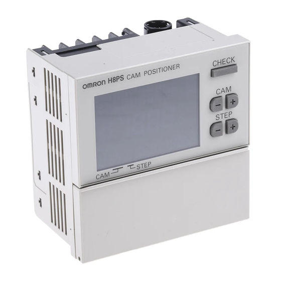
Cam Positioner
H8PS
OPERATION MANUAL
Cat. No. Z199-E1-02
Related Manuals for Omron H8PS
Summary of Contents for Omron H8PS
-
Page 1
Cam Positioner H8PS OPERATION MANUAL Cat. No. Z199-E1-02… -
Page 3
Cam Positioner H8PS OPERATION MANUAL… -
Page 4
This Operation Manual describes how to use the H8PS Cam Positioners. Before using the H8PS Cam Positioner, read this manual carefully so that you can use it correctly. Keep the manual close at hand so that you can refer to it whenever necessary. -
Page 5
Omron’s exclusive warranty is that the Products will be free from defects in materials Warranty and workmanship for a period of twelve months from the date of sale by Omron (or such other period expressed in writing by Omron). Omron disclaims all other war- ranties, express or implied. -
Page 6
It may represent the result of Omron’s test conditions, and the user must correlate it to actual application requirements. Actual performance is subject to the Omron’s Warranty and Limitations of Liability. -
Page 7
Precautions Definition of Safety Notices and Information The following notation is used in this manual to provide precautions required to ensure safe usage of the product. The safety precautions that are provided are extremely important to safety. Always read and heed the information provided in all safety precautions. The following notation is used. -
Page 8
Remove the label after the completion of wiring to ensure proper heat dissipation. Leaving the label attached may occasionally result in fire. Do not disassemble, modify, or repair the H8PS or touch any of the internal parts. Otherwise, minor electric shock, fire, or mal- function may occasionally occur. -
Page 9
• Do not operate the H8PS in locations subject to sudden or extreme changes in temperature, or locations where high humidity may result in condensation. • Do not use the H8PS in locations subject to vibrations or shock. Extended use in such locations may result in damage due to stress. -
Page 10
• Use a switch, relay, or other contact so that the rated power supply voltage will be reached within 0.1 s. If the power supply voltage is not reached quickly enough, the H8PS may malfunction or outputs may be unstable. • Do not turn OFF the power supply when changing or deleting settings. The contents of the EEPROM may be corrupted. -
Page 11
Precautions for Correct Use (1) When using the Y92C-30 Parallel Operation Adapter for parallel operation, do not connect more than two Positioners to the same encoder. (2) Do not subject the connectors of outputs, encoder on the Positioner to more than 30 N of force. -
Page 12
(11) When connecting only one Positioner to the Parallel Operation Adapter, connect the cable with the mark. Connected to the H8PS Connected to the H8PS Y92C-30 From the Dedicated Absolute Encoder… -
Page 13
Explains the features of the H8PS Cam Positioner and gives outlines of its functions. Section 2 INSTALLATION Explains how to mount and wire an H8PS Cam Positioner, and how to connect it to an encoder. Section 3 HOW TO USE THE… -
Page 14
Revision History The revision code of this manual can be found appended to the manual number (referred to as the «catalog number») at the bottom left of the front and back covers. Cat. No. Z199-E1-02 Revision code Revision code Date of revision Page, details of change May 2004 First edition… -
Page 15: Table Of Contents
1.3.1 8-output Model …………….1-7 1.3.2 16-/32-output Model …………… 1-8 Table of Product Models …………….1-9 Nomenclature ………………. 1-11 1.5.1 8-output Models (H8PS-8£) …………1-11 1.5.2 16-/32-output Models (H8PS-16£/-32£) ……..1-12 Section 2 INSTALLATION Designing the System …………….2-2 2.1.1 Selecting the Encoder …………..
-
Page 16
Operation ………………..3-13 Clearing the Settings …………….3-15 3.8.1 Clearing Items Individually …………3-16 3.8.2 All Clear (Deletes all programming) ……….3-17 Checking the Settings in the Run Mode ……….. 3-18 3.10 Switching the Display between Speed and Angle ……..3-19 3.11 All Protection Function ……………. -
Page 17
Section 1 OUTLINE Outline …………….1-2 Features…………….1-3 System Configuration …………1-7 Table of Product Models ………… 1-9 Nomenclature …………..1-11… -
Page 18: Outline
Step 0 Cam output 32 The H8PS Cam Positioner offers a number of advantages over a cam positioner unit of a PLC (program- mable logic controller), including its easy-to-read display and the simple procedure for changing settings. Also you do not have to consider the adverse affect of scan time.
-
Page 19: Features
16 output 32 output output models. ● Available in three There are three series of the H8PS Cam Positioner providing different series with numbers of outputs, i.e., 8, 16 or 32 outputs. The number of outputs can be expanded to a maximum of 64 (using two units of 32-output…
-
Page 20
Section 1 OUTLINE ● Can be used as a The H8PS Cam Positioner can always display the rotational speed and rotation meter present angle on the same display screen. It is also possible to display the rotational speed in enlarged characters as Main display. In… -
Page 21
1.2 Features ■ Convenient/Advanced Functions ● Advance angle This function advances the ON/OFF timing from the preset angle in compensation propor tion to the rotational speed of the machine (encoder). It automatically compensates for the delay in output timing during high- function speed operation, eliminating the need to switch the program according 8 output… -
Page 22
● Step-number limit The H8PS Cam Positioner allows the setting of up to 10 steps (10 sets function of ON/OFF) for each cam (up to 160 steps in total). -
Page 23: System Configuration
1.3 System Configuration 1.3 System Configuration 1.3.1 8-output Model Angle detector (encoder) Angle input signal All outputs (cam, pulse, run) are output from the terminal blocks (M3.5). Output devices Rotation meter…
-
Page 24: 32-Output Model
Section 1 OUTLINE 1.3.2 16-/32-output Model Angle detector (encoder) Angle input signal Control signal The cam output (start, bank, origin) signal is output from the connector. Pulses and RUN output are Output cable output from the terminal blocks (M3.5). Output devices Rotation meter Terminal block…
-
Page 25: Table Of Product Models
■ Cam Positioner Number of Bank Mounting method Output configuration Model outputs function Flush mounting NPN transistor output H8PS-8B PNP transistor output H8PS-8BP 8 outputs Surface mounting/ NPN transistor output H8PS-8BF track mounting PNP transistor output H8PS-8BFP Flush mounting NPN transistor output…
-
Page 26
PFP-100N 1 m × 16 mm (l × t) PFP-100N2 End Plate PFP-M Spacer PFP-S * Ask your OMRON representative about the availability of non-standard lengths. ● Recommended USB Cables Name Recommended manufacturer Specifications Model USB Cable ELECOM CO. Ltd. -
Page 27: Nomenclature
1.5 Nomenclature 1.5 Nomenclature 1.5.1 8-output Models (H8PS-8 ) ● Displays (6) All protect indication (1) Cam output indicator (2) PV/SV indicator (7) Mode indicator (8) Main display (9) Unit indication (3) Rotation display monitor (10) 256 indication (11) Unit indication…
-
Page 28: 32-Output Models (H8Ps-16 /-32 )
Teaching: ON/OFF Angles can be set based on actual machine (Encoder) operation. Manual: ANGLE Keys can be used to set ON/OFF angles. Sets the H8PS rotation direction (rotation display monitor, etc.) to the machine (Encoder) rotation direction. Sets the resolution of the connected Encoder.
-
Page 29
1.5 Nomenclature ● Displays (8) All protect indication (1) Cam output indicator (2) PV/SV indicator (9) Mode indicator 9 10 11 12 13 14 15 16 17 18 19 20 21 22 23 24 25 26 27 28 29 30 (3) Start input (10) Main display 31 32… -
Page 30
Teaching: ON/OFF Angles can be set based on actual machine (Encoder) operation. Manual: ANGLE Keys can be used to set ON/OFF angles. Sets the H8PS rotation direction (rotation display monitor, etc.) to the machine (Encoder) rotation direction. Sets the resolution of the connected Encoder. -
Page 31
Section 2 INSTALLATION Designing the System…………2-2 Mounting (Cam Positioner) ……….2-6 Mounting (Encoder) …………2-15 Wiring …………….2-24… -
Page 32: Designing The System
The three series (eight models) of dedicated absolute encoder products shown below are available. Choose the most appropriate model for your application. Note that the encoders can be used with all the H8PS-series Cam Positioners. Refer to the relevant datasheet for details.
-
Page 33
2.1 Designing the System ■ Ratings and Characteristics Item E6CP-AG5C-C E6C3-AG5C-C E6F-AG5C-C 12 VDC − 10% to 24 VDC +15%, ripple (p-p) 5% max. Rated supply voltage Current consumption 70 mA max. 60 mA max. (*1) Resolution (pulses per 256 (8-bit) 256 (8-bit), 360 (9-bit), or 720 (10-bit) revolution) Output code… -
Page 34
Shaft Coupling for the E6F Axis: 10 mm dia. E69-C10B Extension Cable (*) E69-DF5 (same for E6CP, E6C3, and E6F) Parallel Input Adapter Two Units can operate in parallel. Y92C-30 * Ask your OMRON representative about the availability of non-standard lengths. -
Page 35: Selecting The Output Cable
M3.5 terminal block of the cam positioner unit. No dedicated cable is provided, so the user should prepare the output cable. ■ Models H8PS-16 (16-output model) and H8PS-32 (32-output model) With these models of cam positioner, cam outputs are output from the connector.
-
Page 36: Mounting (Cam Positioner)
Section 2 INSTALLATION 2.2 Mounting (Cam Positioner) 2.2.1 Dimensions ■ Flush Mounting H8PS-8 (8-output Models) 15.2 21.6 M3.5 terminal screw (14.6) 52.9 91.8 91.8 ■ Surface Mounting H8PS-8 F (8-output Models) Terminal cover M3.5 terminal screw (60.6) 22.9 91.8 91.8 121.2…
-
Page 37
2.2 Mounting (Cam Positioner) ■ Flush Mounting H8PS-16 /32 (16-/32-output Models) (14.6) 52.9 91.8 91.8 M3.5 terminal screw 21.6 15.2 ■ Surface Mounting H8PS-16 F /32 F (16-/32-output models) (60.6) 91.8 91.8 121.2 22.9 M3.5 terminal screw Terminal cover… -
Page 38: Mounting Method
Section 2 INSTALLATION 2.2.2 Mounting Method ■ Mounting on the Panel (for all flush mounting models) Panel Cutout (according to DIN 43700) 14.6 52.9 α +0.8 +0.8 11 dia. Mounting screws (2 included) (M4 x 12) Mounting bracket (included) Mounting panel 52.3 + α…
-
Page 39
2.2 Mounting (Cam Positioner) ● Waterproof Cover Y92A-96N Cover dimensions 21.9 +0.8 +0.8 131.7 69.3 115.6 29.4 Use for flush mounting when waterproofing is required. The Y92A-96N conforms to IP66 and NEMA4 (for indoor use) standards for waterproofing. The operating environment may cause the waterproof packing to deteriorate, shrink, or harden. Therefore, it is recommended that the packing be replaced regularly. -
Page 40
Section 2 INSTALLATION ■ Surface Mounting (for all surface-mounting models) ±0.2 81.8 ±0.3 115.2 Four, M4 tap holes Surface Mounting Track Mounting 74.4 (*) 60.6 DIN Track DIN Track Mounting Base Y92F-91 (Order Separately) * This dimension (*) differs depending on the DIN track type (74.4 is only for reference). The illustration shows an 8-output model. -
Page 41
2.2 Mounting (Cam Positioner) ■ DIN Track Mounting Options (sold separately) ● DIN Track Mounting Base Y92F-91 2-11… -
Page 42
Section 2 INSTALLATION ● Mounting Track PFP-100N PFP-50N ±0.15 ±0.3 ±0.15 15 (5)* 1,000 (500)* * Dimensions in parentheses ( ) are for PFP-50N. PFP-100N2 ±0.3 29.2 1,000 2-12… -
Page 43
2.2 Mounting (Cam Positioner) ● End Plate PFP-M M4 x 8 pan-head screws 35.5 35.3 11.5 M4 spring washers ● Spacer PFP-S 34.8 44.3 16.5 2-13… -
Page 44: Encoder Connecting Direction
Section 2 INSTALLATION 2.2.3 Encoder Connecting Direction H8PS-8B H8PS-8BF Encoder Encoder H8PS-16B H8PS-16BF H8PS-32B H8PS-32BF Encoder Output cable Output cable Encoder 2-14…
-
Page 45: Mounting (Encoder)
10 cores (external (*1) (depth: 10) dia.: 6, cross-sectional 16.9 dia. area: 0.18 mm , insulation: 1.0 mm dia.), standard length: 2 m *2: Connector to the H8PS Cam Positioner. • Bracket Mounting Diagram Panel 120° 25 dia. 120° 120° ±0.2 dia.
-
Page 46
Section 2 INSTALLATION ■ E6C3-AG5C-C • Dimensions (58) D cut: Z-phase position (error ±15°) (15) 120° ±0.1 40±0.1 dia. dia. −0.018 dia. −0.021 50 dia. Three, M4 holes (depth: 5) 120°±0.1 Hirose Electric: RP13A-12PD-13SC • Bracket Mounting Diagram Round, shielded vinyl-insulated cord with 12 cores (oil-resistant) (external dia.: 6, cross-sectional area: 0.2 mm 2 , insulation: 1.1 mm dia.), standard length: 1 m * Order coupling E69-C08B separately. -
Page 47
12 cores (external dia.: 6, (*2) cross-sectional area: 0.2 mm (*1) insulation: 1.1 mm dia.), 42.5 standard length: 2 m 16.9 dia. *2: Connector to the H8PS Cam Positioner. (Hirose Electric: RP13A-12PD-13SC) 2,000 • Bracket Mounting Diagram Panel 120° 40 dia. -
Page 48: Accessories (Order Separately)
Section 2 INSTALLATION 2.3.2 Accessories (Order Separately) ■ Shaft Coupling ● Shaft coupling E69-C06B (11) Four, M3 Hexagon (for E6CP) socket-head setscrews (16.4) 6H8 dia. 15 dia. Material: Glass fiber reinforced polybutylene terephtalate resin (PBT) ● Shaft coupling 23.6 E69-C08B Four, M4 Hexagon socket-head setscrews (for E6C3)
-
Page 49
16.9 dia. 16.9 dia. (*1) (*2) (*3) *1: E6F-AG5C-C, E6CP-AG5C-C, and E6C3-AG5C-C Connectors for the H8PS. *2: 6-dia., 12-core shielded cord (cross-sectional area: 0.2 mm , insulation: 1.1 mm dia.), standard length: 5 m *3: Connected to the H8PS Cam Positioner. -
Page 50: Safety Precautions (Encoder)
Section 2 INSTALLATION 2.3.3 Safety Precautions (Encoder) ■ Precautions for Correct Use • Do not subject the E6CP Encoder to oil or water. • The Encoder consists of high-precision components. Handle it with utmost care and do not drop it, otherwise malfunctioning may result. •…
-
Page 51
2.3 Mounting (Encoder) ● Mounting Procedure Do not secure the Coupling and 1. Insert the shaft into the Coupling. shaft with screws at this time. 2. Secure the Encoder. Refer to the table for Maximum insertion Coupling length the maximum insertion lengths of E69-C06B 5.5 mm… -
Page 52: Parallel Input Adapters (Order Separately)
New H8PS Cam Positioners: The encoder input resolution can be 256, 360, or 720. You cannot use the previous and new Cam Positioners together with a Y92C-30 Parallel Input Adapter for parallel operation. If you perform parallel operation, do not combine different types of H8PS Cam Positioners.
-
Page 53
2.3 Mounting (Encoder) 1,030 40.4 8.5 dia. 17 dia. R6.5 14 dia. 11.3 • Panel Surface Mounting Front M4 screw (included) ±1 Two, M4 tap holes • Panel Back Mounting Back M4 nut (included) M4 screw (included) ±1 Two, 4.3 dia. holes 2-23… -
Page 54: Wiring
Section 2 INSTALLATION 2.4 Wiring 2.4.1 System Connection Diagram Absolute encoder E6CP-AG5C-CC E6C3-AG5C-C E6F-AG5C-C PLC, switches, touch panel, etc. Angle data input Control signal input Cam outputs Output cable Pulse outputs Outputs RUN output Rotation meter Terminal block 2-24…
-
Page 55: Terminal Arrangement
24 VDC Encoder NPN Output, NPN Output, Surface Mounting Surface Mounting Encoder H8PS-8 F H8PS-16 F/-32 F 24 VDC 6 7 8 9 10 11 12 13 + − Alignment markings 9 10 11 12 13 (Front view) (Front view)
-
Page 56
Output Output Cable 1 Cable 2 11 13 15 17 19 10 12 14 16 18 20 XG4M-2030 MIL Connector (made by OMRON) Wiring table — Output cable 1 Wiring table — Output cable 2 Connector Connector Connector Connector Output… -
Page 57
2.4 Wiring Note 1. The COM signal on the output connector is connected to the minus terminal of the 24-VDC power input inside the Cam Positioner. Note 2. The Vs signal on the output connector is connected to Vs terminal inside the Cam Positioner. Note 3. -
Page 58
Section 2 INSTALLATION ● Y92S-41-200 Discrete Wire Output Cable (Order Separately) Connections Y92S-41-200 Discrete Wire Output Cable (Order Separately) (CN1) (CN2) Output Cable 1 Output Cable 2 Output Cable 1 Wiring Table Cable Marking Cable Marking Outputs Marks Outputs Marks color color color… -
Page 59: Input Connections
2.4 Wiring 2.4.3 Input Connections Only the Encoder inputs are connected with 8-output Models. For 16-/32-point models, the inputs are no-voltage (short-circuit or open) inputs. ■ No-voltage Inputs <Open Collector> PLC, sensor, etc. Note: Operates when the transistor turns ON. <Contact Input>…
-
Page 60: Output Connections
Section 2 INSTALLATION 2.4.4 Output Connections Internal circuit damage may result from a short circuit in the load. ■ NPN Output Models Outputs Load COM/(−) * Always connect a diode to absorb counter-electromotive force when connecting an inductive load. Cam outputs, Item Pulse output RUN output…
-
Page 61
Section 3 HOW TO USE THE BASIC FUNCTIONS The H8PS Cam Positioners can be operated easily by simply following the operational steps described in this section. Operation Basics …………… 3-2 Preparatory Steps before Starting Operation ….3-4 DIP Switch Setting …………. 3-5 Setting the Origin…………… -
Page 62: How To Use The Basic Functions
Section 3 HOW TO USE THE BASIC FUNCTIONS 3.1 Operation Basics The basics of the operation of the H8PS Cam Positioner are explained below. For more details on operation, refer to «4.1 Mode Transitions». PRGM Programming Mode TEST Change the mode switch setting.
-
Page 63
3.1 Operation Basics ● Operation Modes and Functions Operation Display Outline Main functions mode Programming [PRG] lights. In this mode, programming • Writing cam programs Mode and setting, e.g. writing cam (manual/teach) programs and setting the • Clearing cam programs advance angle compensa- •… -
Page 64: Preparatory Steps Before Starting Operation
Section 3 HOW TO USE THE BASIC FUNCTIONS 3.2 Preparatory Steps before Starting Operation The steps to be followed before starting the operation of the H8PS Cam Positioner are explained below. (The steps described below are a series of preparatory steps before starting H8PS Cam Positioner operation under the default settings.)
-
Page 65: Dip Switch Setting
• When operating the DIP switch, use a tip of tweezers or a tool with a tip approximately 0.8 mm in width. • The DIP switch settings are read to the H8PS Cam Positioner when the power is turned on. • When the resolution selection is changed and read, all types of information including all the…
-
Page 66: Setting The Rotation Direction
• When operating the DIP switch, use a tip of tweezers or a tool with a tip approximately 0.8 mm in width. • The DIP switch settings are read to the H8PS Cam Positioner when the power is turned on. Hint •…
-
Page 67: Setting The Origin
3.4 Setting the Origin 3.4 Setting the Origin This step (origin designation) is necessary to match the origin of the H8PS Cam Positioner with that of the machine (Encoder). Origin designation is necessary when the system is introduced. It is also required in the cases indicated below.
-
Page 68: Setting The On/Off Angles
Section 3 HOW TO USE THE BASIC FUNCTIONS 3.5 Setting the ON/OFF Angles ● The number of ON/OFF angles may be set with up to 10 steps for each cam. programmable With a 32-output model, however, the total number of programmable steps steps is 160 for all cams and if an attempt is made to set ON/OFF angles exceeding this limit, «ful»…
-
Page 69
3.5 Setting the ON/OFF Angles The next pages explain the actual programming steps using the following ON/OFF chart as an example. Setting in the manual mode Cam 2 Cam 3 Setting in the teaching mode… -
Page 70: Setting The On/Off Angles In The Manual Mode (Key Input)
Section 3 HOW TO USE THE BASIC FUNCTIONS 3.5.1 Setting the ON/OFF Angles in the Manual Mode (Key Input) <Example> To set «ON at 25° and OFF at 51°» for Cam 2, Step No. 1 Set the mode switch to PRGM or TEST. PRGM (The explanation below assumes that the switch Selecting the mode…
-
Page 71: Setting The On/Off Angles In The Teach Mode
3.5 Setting the ON/OFF Angles 3.5.2 Setting the ON/OFF Angles in the Teach Mode <Example> To set «ON at 195° and OFF at 278°» for Cam 3, Step No. 2 Set the mode switch to PRGM or TEST. PRGM (The explanation below assumes that the switch Selecting the mode TEST is set to TEST.)
-
Page 72: Checking The Operation Timing
Section 3 HOW TO USE THE BASIC FUNCTIONS 3.6 Checking the Operation Timing Set the mode switch to TEST and check the ON/OFF angles while turning on the outputs. PRGM TEST Operating the machine (Encoder) to confirm the operation timing. If it is not correct, change the set ON/OFF angles.
-
Page 73: Operation
3.7 Operation 3.7 Operation Set the mode switch to RUN to start the operation. PRGM TEST ■ For 16-/32-output Models Be sure to turn ON the start input. («ST» will light on the display.) Cam outputs and the RUN output are not turned ON unless the start input is turned ON.
-
Page 74
Section 3 HOW TO USE THE BASIC FUNCTIONS ■ Differences between the Run Mode and the Test Mode In the Run mode, cam programs cannot be changed. In the Test mode, cam programs can be changed while being executed. Therefore, the Test mode operation can be considered «operation for adjustment purposes.»… -
Page 75: Clearing The Settings
3.8 Clearing the Settings 3.8 Clearing the Settings The two methods for clearing settings are provided: clearing by steps/cams/banks and «all clear», where all the settings are cleared collectively. The table below shows the details of the data to be cleared. (The bank function is available only with 16-/32-output models.) Advance Function…
-
Page 76: Clearing Items Individually
Section 3 HOW TO USE THE BASIC FUNCTIONS 3.8.1 Clearing Items Individually The procedure for clearing individual steps, cams, and banks is explained below. • Set the mode switch to PRGM or TEST. PRGM PRGM TEST TEST • Press the [CLEAR] key for a short time (less than three seconds) to display for clearing items individually.
-
Page 77: All Clear (Deletes All Programming)
3.8 Clearing the Settings 3.8.2 All Clear (Deletes all programming) The section below explains the procedure for clearing all programs. • Set the mode switch to PRGM or TEST. PRGM PRGM TEST TEST • Hold the [CLEAR] key down for at least three seconds to set the all clear mode.
-
Page 78: Checking The Settings In The Run Mode
Section 3 HOW TO USE THE BASIC FUNCTIONS 3.9 Checking the Settings in the Run Mode The section below explains the procedure for checking cam programs in the Run mode. PRGM TEST • Press the [CHECK] key to check the programmed ON/OFF angles. * Operation may be started from any display screen.
-
Page 79: Switching The Display Between Speed And Angle
3.10 Switching the Display between Speed and Angle 3.10 Switching the Display between Speed and Angle The displayed information («Angle» and «Speed») can be switched between Main display and Sub-display (only in the Run mode). Pressing the [ON↑ ↓OFF] key for one second will toggle the information displayed at Main display and Sub-display between «Angle»…
-
Page 80: All Protection Function
Section 3 HOW TO USE THE BASIC FUNCTIONS 3.11 All Protection Function The all protection function disables all operations (keys and switches) in the Run mode. Since the status of the Cam Positioner when the all protection function was enabled remains in memory even after the power is turned off, the settings are protected from incorrect or unauthorized operations.
-
Page 81
Section 4 HOW TO USE THE ADVANCED FUNCTIONS The basic operation of the H8PS Cam Positioner can be mastered by following the expla- nations in Section 3. Section 4 deals with the functions that make operation easier, and the advanced functions. -
Page 82: Mode Transitions
Section 4 HOW TO USE THE ADVANCED FUNCTIONS 4.1 Mode Transitions 8 output 16 output 32 output The H8PS Cam Positioner has the modes shown below. [ADV] key Function Setting Mode 3 s min. PRGM Programming Mode TEST Refer to pages 28 to 30.
-
Page 83
4.1 Mode Transitions Operation Display Outline Main functions mode Programming [PRG] lights. In this mode, programming • Writing cam programs mode and setting, e.g. writing cam (manual/teach) programs and setting ADV • Clearing cam programs values, are performed. • All clear No outputs will be given in •… -
Page 84: Advance Angle Compensation (Adv) Function
Section 4 HOW TO USE THE ADVANCED FUNCTIONS 4.2 Advance Angle Compensation (ADV) Function 8 output 16 output 32 output 4.2.1 What Is the Advance Angle Compensation (ADV) Function? The ADV function advances the ON/OFF timing relative to the preset value and proportional to the Encoder rotation speed.
-
Page 85: Specifications Of Advance Angle Compensation Function Setting
4.2 Advance Angle Compensation (ADV) Function 4.2.2 Specifications of Advance Angle Compensation Function Setting ■ The Number of Advance Angle Compensation Function Setting Enabled Outputs The function can be set for seven outputs (cam No. 1 to 7). (Common to all of the 8-/16-/32-output models) The settings for each of the seven outputs can be made independently.
-
Page 86
Section 4 HOW TO USE THE ADVANCED FUNCTIONS ■ Advance Timing Refreshing Period 200 ms This is the time taken for one cycle, i.e. «measuring the speed/calcu- lating the ADV value/making the output effective». ■ Precautions on Using the Advance Angle Compensation Function ●… -
Page 87
4.2 Advance Angle Compensation (ADV) Function ● Precautions on the As described above, the ADV function executes one «measuring the deceleration stage speed/calculating the advance angle/making the output effective» cycle every 200 ms. This enables to advance the output ON/OFF timing correctly while the speed is accelerating as well as during high-speed operation. -
Page 88
Section 4 HOW TO USE THE ADVANCED FUNCTIONS • Example countermeasures — Make the duration of each output as long as possible. This decreases the possibility that the output will turn on again during a steep deceleration. Make the duration of each output longer while keeping the rising edges at the same ON angle. -
Page 89: Operation
4.2 Advance Angle Compensation (ADV) Function 4.2.3 Operation <Example> Setting an ADV value for cam 4 (speed: 100 r/min, advance angle: 2°) (The same example as explained in «4.2.1 What Is the Advance Angle Compensation (ADV) Function?») Set the mode switch to PRGM or TEST. PRGM PRGM Selecting the mode…
-
Page 90
Section 4 HOW TO USE THE ADVANCED FUNCTIONS Press the [+] or [−] key of the ANGLE keys (*) to Setting the ADV value set the desired ADV value (2°, in this example). * When setting the ADV value by holding the [+] or [−] key down to change the displayed value quickly, the displayed value changes more quickly if the other STEP… -
Page 91: Prohibiting Outputs
4.3 Prohibiting Outputs 4.3 Prohibiting Outputs As explained in «3.7 Operation», with 16-/32-output models, outputs do not turn on unless the «start input» is input. In other words cam outputs are prohibited if the start input is turned off, as shown in the figure below. Note that although the run output turns off if the start input turns off, the pulse outputs are not affected by the turning off of the start input.
-
Page 92: Pulse Output (F1/F2)
The fact that it is also possible to set the pulse output timing allows the H8PS Cam Positioner to be used for setting the system operating timing and similar applications.
-
Page 93: Setting The Number Of Pulse Outputs (F1)
4.4 Pulse Output (F1/F2) 4.4.1 Setting the Number of Pulse Outputs (F1) Set the number of output pulses in the function setting mode. • Parameter Encoder resolution The settable number of pulses 1,2,3,4,5,6, 9,10,12,15,18,20, 30,36, 45,60, 1,2,3,4,5,6, 9,10,12,15,18,20, 30,36, 45,60, 1,2,3,4,5,6, 9,10,12,15,18,20,24,30,36,40, 45,60,72, 90,120, 180,360 * The numbers in Italic indicate the default values.
-
Page 94: Setting The Pulse Output Start Angle (F2)
Section 4 HOW TO USE THE ADVANCED FUNCTIONS 4.4.2 Setting the Pulse Output Start Angle (F2) Set the pulse output start angle in the function setting mode. • Parameter Encoder resolution Pulse output start angle setting range 256 (256 display) 0 to 255 256 (360 display) 0°…
-
Page 95: Speed Alarm (F3/F4)
8 output 16 output 32 output The H8PS Cam Positioner allows the speed alarm function to be allocated to an output in addition to its capability to display the speed. Since «speed alarm (upper limit)» and «speed alarm (lower limit)» are allocated to different outputs, this function can be used in conventional ways to meet the requirements for various applications.
-
Page 96: Setting The Speed Alarm (Upper Limit) (F3)
Section 4 HOW TO USE THE ADVANCED FUNCTIONS 4.5.1 Setting the Speed Alarm (Upper Limit) (F3) Set the speed alarm upper limit using the F3 menu in the function setting mode. ● Parameter Set the speed alarm upper limit. If it is set to «—«, the upper limit speed alarm function is disabled and the output can be used as a normal cam output.
-
Page 97
4.5 Speed Alarm (F3/F4) ■ Operation <Example> Setting the upper limit alarm value to «700 r/min» for a 16-output model With the mode switch set to PRGM, hold the Function setting mode [ADV] key down for at least 3 seconds to enter the function setting mode. -
Page 98: Setting The Speed Alarm (Lower Limit) (F4)
Section 4 HOW TO USE THE ADVANCED FUNCTIONS 4.5.2 Setting the Speed Alarm (Lower Limit) (F4) Set the speed lower limit alarm using the F4 menu in the function setting mode. ● Parameter Set the lower limit alarm speed. If it is set to «—«, the lower limit speed alarm function is disabled and the output can be used as a normal cam output.
-
Page 99
4.5 Speed Alarm (F3/F4) ■ Operation <Example> Setting the lower limit alarm value to 20 r/min for a 16-output model With the mode switch set to PRGM, hold the Function setting mode [ADV] key down for at least 3 seconds to enter the function setting mode. -
Page 100: Step Number Limit (F5)
8 output 16 output 32 output The H8PS Cam Positioner has the capacity to make a 10-step program for each cam. It also has a function to limit the number of programmable steps. The step number limit function may be used in cases where, for example: Making/changing cam programs is to be allowed, but addition of a program by operation errors must be avoided.
-
Page 101
4.6 Step Number Limit (F5) <Example 2> Limiting the number of steps to «1» for cam 3 With the mode switch set to PRGM, hold the Function setting mode [ADV] key down for at least 3 seconds to enter the function setting mode. PRGM TEST STEP… -
Page 102
Section 4 HOW TO USE THE ADVANCED FUNCTIONS ● Precautions on using the step number limit function Before setting the step number limit function, make sure that a program has not been set for the target cam. If this function is set without due care as in the case shown below, a cam program that cannot be checked in the programming mode could run. -
Page 103: Cam Protection (F6)
8 output 16 output 32 output The H8PS Cam Positioner allows protection to be set, in cam units, to disable program writing. The cam protection function may be used in cases like this: The setting of the program of a specific cam number must not be changed.
-
Page 104: Bank Function (F7/F8/F9)
Section 4 HOW TO USE THE ADVANCED FUNCTIONS 4.8 Bank Function (F7/F8/F9) 16 output 32 output 4.8.1 What Is the Bank Function? The bank function is available with 16-/32-output models. The bank function allows switching of the entire cam program. A program can be selected simply by selecting the corresponding bank number when changing the setup.
-
Page 105: Switching The Active Bank
4.8 Bank Function (F7/F8/F9) 4.8.2 Switching the Active Bank The two methods are provided for selecting the bank to be run: selection using the bank input (terminal block) and selection using the [BANK] key on the Cam Positioner unit. For details, refer to the table below. * In the default setting (this includes the status after an «all clear»…
-
Page 106
Section 4 HOW TO USE THE ADVANCED FUNCTIONS ● Bank input terminals Bank input terminals Bank No. ON: Shorted to COM terminal. OFF: Open 4-26… -
Page 107: Designating The Bank Using The Keys
4.8 Bank Function (F7/F8/F9) 4.8.3 Designating the Bank Using the Keys Use the [BANK] key on the front of the Cam Positioner unit to designate the bank in the programming and test mode. Make sure that the display for the bank switching method is «key». (Refer to «4.8.6 Selecting the Bank Switching Method (F8)».) <Example>…
-
Page 108: Bank Switching Timing
T3: 20 ms min. T4: 20 ms min. Refer to «Appendix D Operation Timing Chart» for the operation timing chart for H8PS Cam Positioner. ● Cautions on using If the power is cycled after switching the bank but without setting a new…
-
Page 109: Enabling The Bank (F7)
4.8 Bank Function (F7/F8/F9) 4.8.5 Enabling the Bank (F7) In the default setting, the bank function is disabled. To use the bank function, it must be enabled by using the F7 menu (bank enable/disable) in the function setting mode. ● Parameter Setting data Description no (No)
-
Page 110: Selecting The Bank Switching Method (F8)
Section 4 HOW TO USE THE ADVANCED FUNCTIONS 4.8.6 Selecting the Bank Switching Method (F8) Select the method for switching the active bank using the operation below. ● Parameter Setting data Description in (in) The bank can only be switched by means of the bank input at the terminals.
-
Page 111: Bank Copy (F9)
4.8 Bank Function (F7/F8/F9) 4.8.7 Bank Copy (F9) The bank copy function is used to copy a program in one bank to another. If only some of ON/OFF angles differ between programs, this function makes it easy to create a program with different ON/OFF angles by copying the template program to another bank.
-
Page 112: E24 Detection Enable/Disable (F10)
8 output 16 output 32 output The H8PS Cam Positioner allows the output of an error display (E24) when the connector of the connected Encoder is disconnected. In normal operation the E24 detection function should be enabled to ensure safe operation.
-
Page 113
4.9 E24 Detection Enable/Disable (F10) ■ Operation <Example> Changing the E24 detection function setting to «no (disabled)» With the mode switch set to PRGM, hold the Function setting mode [ADV] key down for at least 3 seconds to enter the function setting mode. PRGM TEST STEP… -
Page 114
Section 4 HOW TO USE THE ADVANCED FUNCTIONS 4-34… -
Page 115: Appendices
APPENDICES Appendix A Specifications (Ratings)……..A-2 Appendix B Troubleshooting……….A-5 Appendix C List of Settings……….A-11 Appendix D Operation Timing Chart ……..A-14 Appendix E Angle Data Table (256 Resolution) ….A-16 Appendix F Coding Sheet…………A-17…
-
Page 116: Appendix A Specifications (Ratings
APPENDICES Appendix A Specifications (Ratings) ■ Ratings and Characteristics ● Ratings Item H8PS- B H8PS- BF H8PS- BP H8PS- BFP 24 VDC Rated supply voltage Operating voltage range 85% to 110% of rated supply voltage Flush mounting Surface mounting, Flush mounting…
-
Page 117
Specifications (Ratings) ● Characteristics 0.5° increments at a resolution of 720, 1° increments at a resolution of Setting unit 256 or 360 (*1) Up to 10 steps can be set for each cam to turn the output ON/OFF 10 Number of steps times. -
Page 118
APPENDICES ● Approved Standards cULus (Listing): UL508/CSA C22.2 No. 14 Approved safety standards (EMI) EN61326 Emission Enclosure: EN55011 Group1 Class A (EMS) EN61326 Immunity ESD: EN61000-4-2: 4 kV contact discharge 8 kV air discharge Immunity RF-interference: EN61000-4-3: 10 V/m (Amplitude-modulated, 80 MHz to 1 GHz) EMC (*) 10 V/m (Pulse-modulated, 900 MHz… -
Page 119: Appendix B Troubleshooting
Troubleshooting Appendix B Troubleshooting ■ Self Diagnostic Function Display Meaning Recovery method Origin designation Press the CLEAR Key for at least 3 s. data error All settings, including the origin designation data, will be initialized. Memory error: Cycle the power supply. RAM error Memory error: Press the CLEAR Key for at least 3 s.
-
Page 120
(changing the In normal processing, i.e., when the DIP switch encoder resolution setting) setting has not been changed, the H8PS Cam Positioner starts running after approximately one second. The display angle does not The DIP switch resolution… -
Page 121
[WRITE] key is pressed. pressed. Pressing the [CLEAR] key simply causes the H8PS Cam Positioner to enter the clear mode. Refer to «3.8 Clearing the Settings» Moving to the ADV function The cam display does not ADV function setting is allowed for cam No. -
Page 122
APPENDICES ■ Problems in RUN Mode Operation Symptom Probable cause Corrective action Some angle display values A 256 resolution/rotation Since the encoder angle is converted to 360° nota- are skipped. (360° notation display) tion to display, some angle values are not dis- encoder is used. -
Page 123
32-output model: cam No. 31 or 32 The RUN output does not The start input is not turned The H8PS Cam Positioner is in the output prohib- turn on. ited state (Refer to «4.3 Prohibiting Outputs») (16-/32-output models) unless the start input is turned on. -
Page 124
Separate the cables from power lines. cycled the power supply. There is noise on the power Attach a ferrite core to power supply line on the AC supply line to the H8PS or input or DC output side. encoder. Disconnect the FG line. -
Page 125: Appendix C List Of Settings
List of Settings Appendix C List of Settings Switch Mode switch PRGM/TEST/RUN PRGM Programming TCH/MAN mode switch No. 1: ON (CW)/OFF (CCW) 3.3.2 switch CW/CCW rotation No. 2: Fixed to ON …
-
Page 126
APPENDICES Func- Select from 1, 2, 3, 4, 5, 6, 9, tion set- No. of pulse 10, 12, 15, 18, 20, 30, 36, 45, ting outputs. 60, 90 (at 256 resolution/rota- mode tion) Select from 1, 2, 3, 4, 5, 6, 9, 10, 12, 15, 18, 20, 30, 36, 45, … -
Page 127
List of Settings Opera- Origin setting tion Cam program- ming Clear Checking the setting Switch to the … -
Page 128: Appendix D Operation Timing Chart
APPENDICES Appendix D Operation Timing Chart ■ Relationship between Start Input and Output (bank not used) Start input Output status Output enabled Output prohibited Output prohibited (Cam output, RUN output) T1: max. 225ms T2: max. 225ms ■ Bank Switching Timing Bank Bank 0 Bank 1…
-
Page 129: Appendix D Operation Timing Chart
Operation Timing Chart ■ Output Response Time <Example> ON angle: 28°, OFF angle: 51° (The response time is not influenced by the set angles.) (in CW rotation) Cam output (in CCW rotation) T: 0.3 ms max. ■ At Power ON/OFF Power Supply Input status Unstable…
-
Page 130: Appendix E Angle Data Table (256 Resolution
APPENDICES Appendix E Angle Data Table (256 Resolution) ■ When a 256 Resolution/rotation Encoder is Used To assist with programming when using an Encoder with a resolution of 256/rotation, displays and settings may be done by conversion to 360 degrees by setting a pin on the DIP switch inside the front cover.
-
Page 131: Appendix F Coding Sheet
Coding Sheet Appendix F Coding Sheet Bank No. Step Name Speed ADV value Speed ADV value Speed ADV value Speed ADV value Speed ADV value Speed ADV value Speed ADV value F1: Number of output pulses F2: Pulse output start angle F3: Speed alarm (upper limit) F4: Speed alarm (lower limit) A-17…
-
Page 132
APPENDICES Bank No. Step Name F1: Number of output pulses F2: Pulse output start angle F3: Speed alarm (upper limit) F4: Speed alarm (lower limit) A-18… -
Page 133
Function setting mode ……. 4-2 campro ……….. 4-23 CE marking ……….A-4 Characteristics ………. A-3 Chart …………A-13 H8PS-SOFT-V1 ……..1-10 hi …………4-16 CHECK key ……….1-12 Checking the operation timing ….3-12 chg …………4-30 CLEAR ………… 3-15 Input connections …….. -
Page 134
List of settings ……… A-10 Self diagnostic function ……A-5 lo …………4-18 Sensor connection ……..2-29 Setting levels ……….4-2 Setting the ON/OFF angles ……. 3-8 Setting the origin ……..3-7 Main display ……….1-11 Shaft coupling ……… 2-18 Maximum number of steps set ….4-20 Spacer …………. -
Page 135
Y92A-96B ……….2-8 Y92A-96N ……….2-9 Y92C-30 ……….2-22 Y92F-91 ……….2-11… -
Page 138
The Netherlands Hoffman Estates, IL 60169 U.S.A Tel: (31)2356-81-300/Fax: (31)2356-81-388 Tel: (1) 847-843-7900/Fax: (1) 847-843-7787 © OMRON Corporation 2004 All Rights Reserved. OMRON (CHINA) CO., LTD. OMRON ASIA PACIFIC PTE. LTD. In the interest of product improvement, Room 2211, Bank of China Tower, No.
-
Page 1
Cam Positioner H8PS OPERATION MANUAL Cat. No. Z199-E1-02… -
Page 3
Cam Positioner H8PS OPERATION MANUAL… -
Page 4
This Operation Manual describes how to use the H8PS Cam Positioners. Before using the H8PS Cam Positioner, read this manual carefully so that you can use it correctly. Keep the manual close at hand so that you can refer to it whenever necessary. -
Page 5
Omron’s exclusive warranty is that the Products will be free from defects in materials Warranty and workmanship for a period of twelve months from the date of sale by Omron (or such other period expressed in writing by Omron). Omron disclaims all other war- ranties, express or implied. -
Page 6
It may represent the result of Omron’s test conditions, and the user must correlate it to actual application requirements. Actual performance is subject to the Omron’s Warranty and Limitations of Liability. -
Page 7
Precautions Definition of Safety Notices and Information The following notation is used in this manual to provide precautions required to ensure safe usage of the product. The safety precautions that are provided are extremely important to safety. Always read and heed the information provided in all safety precautions. The following notation is used. -
Page 8
Remove the label after the completion of wiring to ensure proper heat dissipation. Leaving the label attached may occasionally result in fire. Do not disassemble, modify, or repair the H8PS or touch any of the internal parts. Otherwise, minor electric shock, fire, or mal- function may occasionally occur. -
Page 9
• Do not operate the H8PS in locations subject to sudden or extreme changes in temperature, or locations where high humidity may result in condensation. • Do not use the H8PS in locations subject to vibrations or shock. Extended use in such locations may result in damage due to stress. -
Page 10
• Use a switch, relay, or other contact so that the rated power supply voltage will be reached within 0.1 s. If the power supply voltage is not reached quickly enough, the H8PS may malfunction or outputs may be unstable. • Do not turn OFF the power supply when changing or deleting settings. The contents of the EEPROM may be corrupted. -
Page 11
Precautions for Correct Use (1) When using the Y92C-30 Parallel Operation Adapter for parallel operation, do not connect more than two Positioners to the same encoder. (2) Do not subject the connectors of outputs, encoder on the Positioner to more than 30 N of force. -
Page 12
(11) When connecting only one Positioner to the Parallel Operation Adapter, connect the cable with the mark. Connected to the H8PS Connected to the H8PS Y92C-30 From the Dedicated Absolute Encoder… -
Page 13
Explains the features of the H8PS Cam Positioner and gives outlines of its functions. Section 2 INSTALLATION Explains how to mount and wire an H8PS Cam Positioner, and how to connect it to an encoder. Section 3 HOW TO USE THE… -
Page 14
Revision History The revision code of this manual can be found appended to the manual number (referred to as the «catalog number») at the bottom left of the front and back covers. Cat. No. Z199-E1-02 Revision code Revision code Date of revision Page, details of change May 2004 First edition… -
Page 15: Table Of Contents
1.3.1 8-output Model …………….1-7 1.3.2 16-/32-output Model …………… 1-8 Table of Product Models …………….1-9 Nomenclature ………………. 1-11 1.5.1 8-output Models (H8PS-8£) …………1-11 1.5.2 16-/32-output Models (H8PS-16£/-32£) ……..1-12 Section 2 INSTALLATION Designing the System …………….2-2 2.1.1 Selecting the Encoder …………..
-
Page 16
Operation ………………..3-13 Clearing the Settings …………….3-15 3.8.1 Clearing Items Individually …………3-16 3.8.2 All Clear (Deletes all programming) ……….3-17 Checking the Settings in the Run Mode ……….. 3-18 3.10 Switching the Display between Speed and Angle ……..3-19 3.11 All Protection Function ……………. -
Page 17
Section 1 OUTLINE Outline …………….1-2 Features…………….1-3 System Configuration …………1-7 Table of Product Models ………… 1-9 Nomenclature …………..1-11… -
Page 18: Outline
Step 0 Cam output 32 The H8PS Cam Positioner offers a number of advantages over a cam positioner unit of a PLC (program- mable logic controller), including its easy-to-read display and the simple procedure for changing settings. Also you do not have to consider the adverse affect of scan time.
-
Page 19: Features
16 output 32 output output models. ● Available in three There are three series of the H8PS Cam Positioner providing different series with numbers of outputs, i.e., 8, 16 or 32 outputs. The number of outputs can be expanded to a maximum of 64 (using two units of 32-output…
-
Page 20
Section 1 OUTLINE ● Can be used as a The H8PS Cam Positioner can always display the rotational speed and rotation meter present angle on the same display screen. It is also possible to display the rotational speed in enlarged characters as Main display. In… -
Page 21
1.2 Features ■ Convenient/Advanced Functions ● Advance angle This function advances the ON/OFF timing from the preset angle in compensation propor tion to the rotational speed of the machine (encoder). It automatically compensates for the delay in output timing during high- function speed operation, eliminating the need to switch the program according 8 output… -
Page 22
● Step-number limit The H8PS Cam Positioner allows the setting of up to 10 steps (10 sets function of ON/OFF) for each cam (up to 160 steps in total). -
Page 23: System Configuration
1.3 System Configuration 1.3 System Configuration 1.3.1 8-output Model Angle detector (encoder) Angle input signal All outputs (cam, pulse, run) are output from the terminal blocks (M3.5). Output devices Rotation meter…
-
Page 24: 32-Output Model
Section 1 OUTLINE 1.3.2 16-/32-output Model Angle detector (encoder) Angle input signal Control signal The cam output (start, bank, origin) signal is output from the connector. Pulses and RUN output are Output cable output from the terminal blocks (M3.5). Output devices Rotation meter Terminal block…
-
Page 25: Table Of Product Models
■ Cam Positioner Number of Bank Mounting method Output configuration Model outputs function Flush mounting NPN transistor output H8PS-8B PNP transistor output H8PS-8BP 8 outputs Surface mounting/ NPN transistor output H8PS-8BF track mounting PNP transistor output H8PS-8BFP Flush mounting NPN transistor output…
-
Page 26
PFP-100N 1 m × 16 mm (l × t) PFP-100N2 End Plate PFP-M Spacer PFP-S * Ask your OMRON representative about the availability of non-standard lengths. ● Recommended USB Cables Name Recommended manufacturer Specifications Model USB Cable ELECOM CO. Ltd. -
Page 27: Nomenclature
1.5 Nomenclature 1.5 Nomenclature 1.5.1 8-output Models (H8PS-8 ) ● Displays (6) All protect indication (1) Cam output indicator (2) PV/SV indicator (7) Mode indicator (8) Main display (9) Unit indication (3) Rotation display monitor (10) 256 indication (11) Unit indication…
-
Page 28: 32-Output Models (H8Ps-16 /-32 )
Teaching: ON/OFF Angles can be set based on actual machine (Encoder) operation. Manual: ANGLE Keys can be used to set ON/OFF angles. Sets the H8PS rotation direction (rotation display monitor, etc.) to the machine (Encoder) rotation direction. Sets the resolution of the connected Encoder.
-
Page 29
1.5 Nomenclature ● Displays (8) All protect indication (1) Cam output indicator (2) PV/SV indicator (9) Mode indicator 9 10 11 12 13 14 15 16 17 18 19 20 21 22 23 24 25 26 27 28 29 30 (3) Start input (10) Main display 31 32… -
Page 30
Teaching: ON/OFF Angles can be set based on actual machine (Encoder) operation. Manual: ANGLE Keys can be used to set ON/OFF angles. Sets the H8PS rotation direction (rotation display monitor, etc.) to the machine (Encoder) rotation direction. Sets the resolution of the connected Encoder. -
Page 31
Section 2 INSTALLATION Designing the System…………2-2 Mounting (Cam Positioner) ……….2-6 Mounting (Encoder) …………2-15 Wiring …………….2-24… -
Page 32: Designing The System
The three series (eight models) of dedicated absolute encoder products shown below are available. Choose the most appropriate model for your application. Note that the encoders can be used with all the H8PS-series Cam Positioners. Refer to the relevant datasheet for details.
-
Page 33
2.1 Designing the System ■ Ratings and Characteristics Item E6CP-AG5C-C E6C3-AG5C-C E6F-AG5C-C 12 VDC − 10% to 24 VDC +15%, ripple (p-p) 5% max. Rated supply voltage Current consumption 70 mA max. 60 mA max. (*1) Resolution (pulses per 256 (8-bit) 256 (8-bit), 360 (9-bit), or 720 (10-bit) revolution) Output code… -
Page 34
Shaft Coupling for the E6F Axis: 10 mm dia. E69-C10B Extension Cable (*) E69-DF5 (same for E6CP, E6C3, and E6F) Parallel Input Adapter Two Units can operate in parallel. Y92C-30 * Ask your OMRON representative about the availability of non-standard lengths. -
Page 35: Selecting The Output Cable
M3.5 terminal block of the cam positioner unit. No dedicated cable is provided, so the user should prepare the output cable. ■ Models H8PS-16 (16-output model) and H8PS-32 (32-output model) With these models of cam positioner, cam outputs are output from the connector.
-
Page 36: Mounting (Cam Positioner)
Section 2 INSTALLATION 2.2 Mounting (Cam Positioner) 2.2.1 Dimensions ■ Flush Mounting H8PS-8 (8-output Models) 15.2 21.6 M3.5 terminal screw (14.6) 52.9 91.8 91.8 ■ Surface Mounting H8PS-8 F (8-output Models) Terminal cover M3.5 terminal screw (60.6) 22.9 91.8 91.8 121.2…
-
Page 37
2.2 Mounting (Cam Positioner) ■ Flush Mounting H8PS-16 /32 (16-/32-output Models) (14.6) 52.9 91.8 91.8 M3.5 terminal screw 21.6 15.2 ■ Surface Mounting H8PS-16 F /32 F (16-/32-output models) (60.6) 91.8 91.8 121.2 22.9 M3.5 terminal screw Terminal cover… -
Page 38: Mounting Method
Section 2 INSTALLATION 2.2.2 Mounting Method ■ Mounting on the Panel (for all flush mounting models) Panel Cutout (according to DIN 43700) 14.6 52.9 α +0.8 +0.8 11 dia. Mounting screws (2 included) (M4 x 12) Mounting bracket (included) Mounting panel 52.3 + α…
-
Page 39
2.2 Mounting (Cam Positioner) ● Waterproof Cover Y92A-96N Cover dimensions 21.9 +0.8 +0.8 131.7 69.3 115.6 29.4 Use for flush mounting when waterproofing is required. The Y92A-96N conforms to IP66 and NEMA4 (for indoor use) standards for waterproofing. The operating environment may cause the waterproof packing to deteriorate, shrink, or harden. Therefore, it is recommended that the packing be replaced regularly. -
Page 40
Section 2 INSTALLATION ■ Surface Mounting (for all surface-mounting models) ±0.2 81.8 ±0.3 115.2 Four, M4 tap holes Surface Mounting Track Mounting 74.4 (*) 60.6 DIN Track DIN Track Mounting Base Y92F-91 (Order Separately) * This dimension (*) differs depending on the DIN track type (74.4 is only for reference). The illustration shows an 8-output model. -
Page 41
2.2 Mounting (Cam Positioner) ■ DIN Track Mounting Options (sold separately) ● DIN Track Mounting Base Y92F-91 2-11… -
Page 42
Section 2 INSTALLATION ● Mounting Track PFP-100N PFP-50N ±0.15 ±0.3 ±0.15 15 (5)* 1,000 (500)* * Dimensions in parentheses ( ) are for PFP-50N. PFP-100N2 ±0.3 29.2 1,000 2-12… -
Page 43
2.2 Mounting (Cam Positioner) ● End Plate PFP-M M4 x 8 pan-head screws 35.5 35.3 11.5 M4 spring washers ● Spacer PFP-S 34.8 44.3 16.5 2-13… -
Page 44: Encoder Connecting Direction
Section 2 INSTALLATION 2.2.3 Encoder Connecting Direction H8PS-8B H8PS-8BF Encoder Encoder H8PS-16B H8PS-16BF H8PS-32B H8PS-32BF Encoder Output cable Output cable Encoder 2-14…
-
Page 45: Mounting (Encoder)
10 cores (external (*1) (depth: 10) dia.: 6, cross-sectional 16.9 dia. area: 0.18 mm , insulation: 1.0 mm dia.), standard length: 2 m *2: Connector to the H8PS Cam Positioner. • Bracket Mounting Diagram Panel 120° 25 dia. 120° 120° ±0.2 dia.
-
Page 46
Section 2 INSTALLATION ■ E6C3-AG5C-C • Dimensions (58) D cut: Z-phase position (error ±15°) (15) 120° ±0.1 40±0.1 dia. dia. −0.018 dia. −0.021 50 dia. Three, M4 holes (depth: 5) 120°±0.1 Hirose Electric: RP13A-12PD-13SC • Bracket Mounting Diagram Round, shielded vinyl-insulated cord with 12 cores (oil-resistant) (external dia.: 6, cross-sectional area: 0.2 mm 2 , insulation: 1.1 mm dia.), standard length: 1 m * Order coupling E69-C08B separately. -
Page 47
12 cores (external dia.: 6, (*2) cross-sectional area: 0.2 mm (*1) insulation: 1.1 mm dia.), 42.5 standard length: 2 m 16.9 dia. *2: Connector to the H8PS Cam Positioner. (Hirose Electric: RP13A-12PD-13SC) 2,000 • Bracket Mounting Diagram Panel 120° 40 dia. -
Page 48: Accessories (Order Separately)
Section 2 INSTALLATION 2.3.2 Accessories (Order Separately) ■ Shaft Coupling ● Shaft coupling E69-C06B (11) Four, M3 Hexagon (for E6CP) socket-head setscrews (16.4) 6H8 dia. 15 dia. Material: Glass fiber reinforced polybutylene terephtalate resin (PBT) ● Shaft coupling 23.6 E69-C08B Four, M4 Hexagon socket-head setscrews (for E6C3)
-
Page 49
16.9 dia. 16.9 dia. (*1) (*2) (*3) *1: E6F-AG5C-C, E6CP-AG5C-C, and E6C3-AG5C-C Connectors for the H8PS. *2: 6-dia., 12-core shielded cord (cross-sectional area: 0.2 mm , insulation: 1.1 mm dia.), standard length: 5 m *3: Connected to the H8PS Cam Positioner. -
Page 50: Safety Precautions (Encoder)
Section 2 INSTALLATION 2.3.3 Safety Precautions (Encoder) ■ Precautions for Correct Use • Do not subject the E6CP Encoder to oil or water. • The Encoder consists of high-precision components. Handle it with utmost care and do not drop it, otherwise malfunctioning may result. •…
-
Page 51
2.3 Mounting (Encoder) ● Mounting Procedure Do not secure the Coupling and 1. Insert the shaft into the Coupling. shaft with screws at this time. 2. Secure the Encoder. Refer to the table for Maximum insertion Coupling length the maximum insertion lengths of E69-C06B 5.5 mm… -
Page 52: Parallel Input Adapters (Order Separately)
New H8PS Cam Positioners: The encoder input resolution can be 256, 360, or 720. You cannot use the previous and new Cam Positioners together with a Y92C-30 Parallel Input Adapter for parallel operation. If you perform parallel operation, do not combine different types of H8PS Cam Positioners.
-
Page 53
2.3 Mounting (Encoder) 1,030 40.4 8.5 dia. 17 dia. R6.5 14 dia. 11.3 • Panel Surface Mounting Front M4 screw (included) ±1 Two, M4 tap holes • Panel Back Mounting Back M4 nut (included) M4 screw (included) ±1 Two, 4.3 dia. holes 2-23… -
Page 54: Wiring
Section 2 INSTALLATION 2.4 Wiring 2.4.1 System Connection Diagram Absolute encoder E6CP-AG5C-CC E6C3-AG5C-C E6F-AG5C-C PLC, switches, touch panel, etc. Angle data input Control signal input Cam outputs Output cable Pulse outputs Outputs RUN output Rotation meter Terminal block 2-24…
-
Page 55: Terminal Arrangement
24 VDC Encoder NPN Output, NPN Output, Surface Mounting Surface Mounting Encoder H8PS-8 F H8PS-16 F/-32 F 24 VDC 6 7 8 9 10 11 12 13 + − Alignment markings 9 10 11 12 13 (Front view) (Front view)
-
Page 56
Output Output Cable 1 Cable 2 11 13 15 17 19 10 12 14 16 18 20 XG4M-2030 MIL Connector (made by OMRON) Wiring table — Output cable 1 Wiring table — Output cable 2 Connector Connector Connector Connector Output… -
Page 57
2.4 Wiring Note 1. The COM signal on the output connector is connected to the minus terminal of the 24-VDC power input inside the Cam Positioner. Note 2. The Vs signal on the output connector is connected to Vs terminal inside the Cam Positioner. Note 3. -
Page 58
Section 2 INSTALLATION ● Y92S-41-200 Discrete Wire Output Cable (Order Separately) Connections Y92S-41-200 Discrete Wire Output Cable (Order Separately) (CN1) (CN2) Output Cable 1 Output Cable 2 Output Cable 1 Wiring Table Cable Marking Cable Marking Outputs Marks Outputs Marks color color color… -
Page 59: Input Connections
2.4 Wiring 2.4.3 Input Connections Only the Encoder inputs are connected with 8-output Models. For 16-/32-point models, the inputs are no-voltage (short-circuit or open) inputs. ■ No-voltage Inputs <Open Collector> PLC, sensor, etc. Note: Operates when the transistor turns ON. <Contact Input>…
-
Page 60: Output Connections
Section 2 INSTALLATION 2.4.4 Output Connections Internal circuit damage may result from a short circuit in the load. ■ NPN Output Models Outputs Load COM/(−) * Always connect a diode to absorb counter-electromotive force when connecting an inductive load. Cam outputs, Item Pulse output RUN output…
-
Page 61
Section 3 HOW TO USE THE BASIC FUNCTIONS The H8PS Cam Positioners can be operated easily by simply following the operational steps described in this section. Operation Basics …………… 3-2 Preparatory Steps before Starting Operation ….3-4 DIP Switch Setting …………. 3-5 Setting the Origin…………… -
Page 62: How To Use The Basic Functions
Section 3 HOW TO USE THE BASIC FUNCTIONS 3.1 Operation Basics The basics of the operation of the H8PS Cam Positioner are explained below. For more details on operation, refer to «4.1 Mode Transitions». PRGM Programming Mode TEST Change the mode switch setting.
-
Page 63
3.1 Operation Basics ● Operation Modes and Functions Operation Display Outline Main functions mode Programming [PRG] lights. In this mode, programming • Writing cam programs Mode and setting, e.g. writing cam (manual/teach) programs and setting the • Clearing cam programs advance angle compensa- •… -
Page 64: Preparatory Steps Before Starting Operation
Section 3 HOW TO USE THE BASIC FUNCTIONS 3.2 Preparatory Steps before Starting Operation The steps to be followed before starting the operation of the H8PS Cam Positioner are explained below. (The steps described below are a series of preparatory steps before starting H8PS Cam Positioner operation under the default settings.)
-
Page 65: Dip Switch Setting
• When operating the DIP switch, use a tip of tweezers or a tool with a tip approximately 0.8 mm in width. • The DIP switch settings are read to the H8PS Cam Positioner when the power is turned on. • When the resolution selection is changed and read, all types of information including all the…
-
Page 66: Setting The Rotation Direction
• When operating the DIP switch, use a tip of tweezers or a tool with a tip approximately 0.8 mm in width. • The DIP switch settings are read to the H8PS Cam Positioner when the power is turned on. Hint •…
-
Page 67: Setting The Origin
3.4 Setting the Origin 3.4 Setting the Origin This step (origin designation) is necessary to match the origin of the H8PS Cam Positioner with that of the machine (Encoder). Origin designation is necessary when the system is introduced. It is also required in the cases indicated below.
-
Page 68: Setting The On/Off Angles
Section 3 HOW TO USE THE BASIC FUNCTIONS 3.5 Setting the ON/OFF Angles ● The number of ON/OFF angles may be set with up to 10 steps for each cam. programmable With a 32-output model, however, the total number of programmable steps steps is 160 for all cams and if an attempt is made to set ON/OFF angles exceeding this limit, «ful»…
-
Page 69
3.5 Setting the ON/OFF Angles The next pages explain the actual programming steps using the following ON/OFF chart as an example. Setting in the manual mode Cam 2 Cam 3 Setting in the teaching mode… -
Page 70: Setting The On/Off Angles In The Manual Mode (Key Input)
Section 3 HOW TO USE THE BASIC FUNCTIONS 3.5.1 Setting the ON/OFF Angles in the Manual Mode (Key Input) <Example> To set «ON at 25° and OFF at 51°» for Cam 2, Step No. 1 Set the mode switch to PRGM or TEST. PRGM (The explanation below assumes that the switch Selecting the mode…
-
Page 71: Setting The On/Off Angles In The Teach Mode
3.5 Setting the ON/OFF Angles 3.5.2 Setting the ON/OFF Angles in the Teach Mode <Example> To set «ON at 195° and OFF at 278°» for Cam 3, Step No. 2 Set the mode switch to PRGM or TEST. PRGM (The explanation below assumes that the switch Selecting the mode TEST is set to TEST.)
-
Page 72: Checking The Operation Timing
Section 3 HOW TO USE THE BASIC FUNCTIONS 3.6 Checking the Operation Timing Set the mode switch to TEST and check the ON/OFF angles while turning on the outputs. PRGM TEST Operating the machine (Encoder) to confirm the operation timing. If it is not correct, change the set ON/OFF angles.
-
Page 73: Operation
3.7 Operation 3.7 Operation Set the mode switch to RUN to start the operation. PRGM TEST ■ For 16-/32-output Models Be sure to turn ON the start input. («ST» will light on the display.) Cam outputs and the RUN output are not turned ON unless the start input is turned ON.
-
Page 74
Section 3 HOW TO USE THE BASIC FUNCTIONS ■ Differences between the Run Mode and the Test Mode In the Run mode, cam programs cannot be changed. In the Test mode, cam programs can be changed while being executed. Therefore, the Test mode operation can be considered «operation for adjustment purposes.»… -
Page 75: Clearing The Settings
3.8 Clearing the Settings 3.8 Clearing the Settings The two methods for clearing settings are provided: clearing by steps/cams/banks and «all clear», where all the settings are cleared collectively. The table below shows the details of the data to be cleared. (The bank function is available only with 16-/32-output models.) Advance Function…
-
Page 76: Clearing Items Individually
Section 3 HOW TO USE THE BASIC FUNCTIONS 3.8.1 Clearing Items Individually The procedure for clearing individual steps, cams, and banks is explained below. • Set the mode switch to PRGM or TEST. PRGM PRGM TEST TEST • Press the [CLEAR] key for a short time (less than three seconds) to display for clearing items individually.
-
Page 77: All Clear (Deletes All Programming)
3.8 Clearing the Settings 3.8.2 All Clear (Deletes all programming) The section below explains the procedure for clearing all programs. • Set the mode switch to PRGM or TEST. PRGM PRGM TEST TEST • Hold the [CLEAR] key down for at least three seconds to set the all clear mode.
-
Page 78: Checking The Settings In The Run Mode
Section 3 HOW TO USE THE BASIC FUNCTIONS 3.9 Checking the Settings in the Run Mode The section below explains the procedure for checking cam programs in the Run mode. PRGM TEST • Press the [CHECK] key to check the programmed ON/OFF angles. * Operation may be started from any display screen.
-
Page 79: Switching The Display Between Speed And Angle
3.10 Switching the Display between Speed and Angle 3.10 Switching the Display between Speed and Angle The displayed information («Angle» and «Speed») can be switched between Main display and Sub-display (only in the Run mode). Pressing the [ON↑ ↓OFF] key for one second will toggle the information displayed at Main display and Sub-display between «Angle»…
-
Page 80: All Protection Function
Section 3 HOW TO USE THE BASIC FUNCTIONS 3.11 All Protection Function The all protection function disables all operations (keys and switches) in the Run mode. Since the status of the Cam Positioner when the all protection function was enabled remains in memory even after the power is turned off, the settings are protected from incorrect or unauthorized operations.
-
Page 81
Section 4 HOW TO USE THE ADVANCED FUNCTIONS The basic operation of the H8PS Cam Positioner can be mastered by following the expla- nations in Section 3. Section 4 deals with the functions that make operation easier, and the advanced functions. -
Page 82: Mode Transitions
Section 4 HOW TO USE THE ADVANCED FUNCTIONS 4.1 Mode Transitions 8 output 16 output 32 output The H8PS Cam Positioner has the modes shown below. [ADV] key Function Setting Mode 3 s min. PRGM Programming Mode TEST Refer to pages 28 to 30.
-
Page 83
4.1 Mode Transitions Operation Display Outline Main functions mode Programming [PRG] lights. In this mode, programming • Writing cam programs mode and setting, e.g. writing cam (manual/teach) programs and setting ADV • Clearing cam programs values, are performed. • All clear No outputs will be given in •… -
Page 84: Advance Angle Compensation (Adv) Function
Section 4 HOW TO USE THE ADVANCED FUNCTIONS 4.2 Advance Angle Compensation (ADV) Function 8 output 16 output 32 output 4.2.1 What Is the Advance Angle Compensation (ADV) Function? The ADV function advances the ON/OFF timing relative to the preset value and proportional to the Encoder rotation speed.
-
Page 85: Specifications Of Advance Angle Compensation Function Setting
4.2 Advance Angle Compensation (ADV) Function 4.2.2 Specifications of Advance Angle Compensation Function Setting ■ The Number of Advance Angle Compensation Function Setting Enabled Outputs The function can be set for seven outputs (cam No. 1 to 7). (Common to all of the 8-/16-/32-output models) The settings for each of the seven outputs can be made independently.
-
Page 86
Section 4 HOW TO USE THE ADVANCED FUNCTIONS ■ Advance Timing Refreshing Period 200 ms This is the time taken for one cycle, i.e. «measuring the speed/calcu- lating the ADV value/making the output effective». ■ Precautions on Using the Advance Angle Compensation Function ●… -
Page 87
4.2 Advance Angle Compensation (ADV) Function ● Precautions on the As described above, the ADV function executes one «measuring the deceleration stage speed/calculating the advance angle/making the output effective» cycle every 200 ms. This enables to advance the output ON/OFF timing correctly while the speed is accelerating as well as during high-speed operation. -
Page 88
Section 4 HOW TO USE THE ADVANCED FUNCTIONS • Example countermeasures — Make the duration of each output as long as possible. This decreases the possibility that the output will turn on again during a steep deceleration. Make the duration of each output longer while keeping the rising edges at the same ON angle. -
Page 89: Operation
4.2 Advance Angle Compensation (ADV) Function 4.2.3 Operation <Example> Setting an ADV value for cam 4 (speed: 100 r/min, advance angle: 2°) (The same example as explained in «4.2.1 What Is the Advance Angle Compensation (ADV) Function?») Set the mode switch to PRGM or TEST. PRGM PRGM Selecting the mode…
-
Page 90
Section 4 HOW TO USE THE ADVANCED FUNCTIONS Press the [+] or [−] key of the ANGLE keys (*) to Setting the ADV value set the desired ADV value (2°, in this example). * When setting the ADV value by holding the [+] or [−] key down to change the displayed value quickly, the displayed value changes more quickly if the other STEP… -
Page 91: Prohibiting Outputs
4.3 Prohibiting Outputs 4.3 Prohibiting Outputs As explained in «3.7 Operation», with 16-/32-output models, outputs do not turn on unless the «start input» is input. In other words cam outputs are prohibited if the start input is turned off, as shown in the figure below. Note that although the run output turns off if the start input turns off, the pulse outputs are not affected by the turning off of the start input.
-
Page 92: Pulse Output (F1/F2)
The fact that it is also possible to set the pulse output timing allows the H8PS Cam Positioner to be used for setting the system operating timing and similar applications.
-
Page 93: Setting The Number Of Pulse Outputs (F1)
4.4 Pulse Output (F1/F2) 4.4.1 Setting the Number of Pulse Outputs (F1) Set the number of output pulses in the function setting mode. • Parameter Encoder resolution The settable number of pulses 1,2,3,4,5,6, 9,10,12,15,18,20, 30,36, 45,60, 1,2,3,4,5,6, 9,10,12,15,18,20, 30,36, 45,60, 1,2,3,4,5,6, 9,10,12,15,18,20,24,30,36,40, 45,60,72, 90,120, 180,360 * The numbers in Italic indicate the default values.
-
Page 94: Setting The Pulse Output Start Angle (F2)
Section 4 HOW TO USE THE ADVANCED FUNCTIONS 4.4.2 Setting the Pulse Output Start Angle (F2) Set the pulse output start angle in the function setting mode. • Parameter Encoder resolution Pulse output start angle setting range 256 (256 display) 0 to 255 256 (360 display) 0°…
-
Page 95: Speed Alarm (F3/F4)
8 output 16 output 32 output The H8PS Cam Positioner allows the speed alarm function to be allocated to an output in addition to its capability to display the speed. Since «speed alarm (upper limit)» and «speed alarm (lower limit)» are allocated to different outputs, this function can be used in conventional ways to meet the requirements for various applications.
-
Page 96: Setting The Speed Alarm (Upper Limit) (F3)
Section 4 HOW TO USE THE ADVANCED FUNCTIONS 4.5.1 Setting the Speed Alarm (Upper Limit) (F3) Set the speed alarm upper limit using the F3 menu in the function setting mode. ● Parameter Set the speed alarm upper limit. If it is set to «—«, the upper limit speed alarm function is disabled and the output can be used as a normal cam output.
-
Page 97
4.5 Speed Alarm (F3/F4) ■ Operation <Example> Setting the upper limit alarm value to «700 r/min» for a 16-output model With the mode switch set to PRGM, hold the Function setting mode [ADV] key down for at least 3 seconds to enter the function setting mode. -
Page 98: Setting The Speed Alarm (Lower Limit) (F4)
Section 4 HOW TO USE THE ADVANCED FUNCTIONS 4.5.2 Setting the Speed Alarm (Lower Limit) (F4) Set the speed lower limit alarm using the F4 menu in the function setting mode. ● Parameter Set the lower limit alarm speed. If it is set to «—«, the lower limit speed alarm function is disabled and the output can be used as a normal cam output.
-
Page 99
4.5 Speed Alarm (F3/F4) ■ Operation <Example> Setting the lower limit alarm value to 20 r/min for a 16-output model With the mode switch set to PRGM, hold the Function setting mode [ADV] key down for at least 3 seconds to enter the function setting mode. -
Page 100: Step Number Limit (F5)
8 output 16 output 32 output The H8PS Cam Positioner has the capacity to make a 10-step program for each cam. It also has a function to limit the number of programmable steps. The step number limit function may be used in cases where, for example: Making/changing cam programs is to be allowed, but addition of a program by operation errors must be avoided.
-
Page 101
4.6 Step Number Limit (F5) <Example 2> Limiting the number of steps to «1» for cam 3 With the mode switch set to PRGM, hold the Function setting mode [ADV] key down for at least 3 seconds to enter the function setting mode. PRGM TEST STEP… -
Page 102
Section 4 HOW TO USE THE ADVANCED FUNCTIONS ● Precautions on using the step number limit function Before setting the step number limit function, make sure that a program has not been set for the target cam. If this function is set without due care as in the case shown below, a cam program that cannot be checked in the programming mode could run. -
Page 103: Cam Protection (F6)
8 output 16 output 32 output The H8PS Cam Positioner allows protection to be set, in cam units, to disable program writing. The cam protection function may be used in cases like this: The setting of the program of a specific cam number must not be changed.
-
Page 104: Bank Function (F7/F8/F9)
Section 4 HOW TO USE THE ADVANCED FUNCTIONS 4.8 Bank Function (F7/F8/F9) 16 output 32 output 4.8.1 What Is the Bank Function? The bank function is available with 16-/32-output models. The bank function allows switching of the entire cam program. A program can be selected simply by selecting the corresponding bank number when changing the setup.
-
Page 105: Switching The Active Bank
4.8 Bank Function (F7/F8/F9) 4.8.2 Switching the Active Bank The two methods are provided for selecting the bank to be run: selection using the bank input (terminal block) and selection using the [BANK] key on the Cam Positioner unit. For details, refer to the table below. * In the default setting (this includes the status after an «all clear»…
-
Page 106
Section 4 HOW TO USE THE ADVANCED FUNCTIONS ● Bank input terminals Bank input terminals Bank No. ON: Shorted to COM terminal. OFF: Open 4-26… -
Page 107: Designating The Bank Using The Keys
4.8 Bank Function (F7/F8/F9) 4.8.3 Designating the Bank Using the Keys Use the [BANK] key on the front of the Cam Positioner unit to designate the bank in the programming and test mode. Make sure that the display for the bank switching method is «key». (Refer to «4.8.6 Selecting the Bank Switching Method (F8)».) <Example>…
-
Page 108: Bank Switching Timing
T3: 20 ms min. T4: 20 ms min. Refer to «Appendix D Operation Timing Chart» for the operation timing chart for H8PS Cam Positioner. ● Cautions on using If the power is cycled after switching the bank but without setting a new…
-
Page 109: Enabling The Bank (F7)
4.8 Bank Function (F7/F8/F9) 4.8.5 Enabling the Bank (F7) In the default setting, the bank function is disabled. To use the bank function, it must be enabled by using the F7 menu (bank enable/disable) in the function setting mode. ● Parameter Setting data Description no (No)
-
Page 110: Selecting The Bank Switching Method (F8)
Section 4 HOW TO USE THE ADVANCED FUNCTIONS 4.8.6 Selecting the Bank Switching Method (F8) Select the method for switching the active bank using the operation below. ● Parameter Setting data Description in (in) The bank can only be switched by means of the bank input at the terminals.
-
Page 111: Bank Copy (F9)
4.8 Bank Function (F7/F8/F9) 4.8.7 Bank Copy (F9) The bank copy function is used to copy a program in one bank to another. If only some of ON/OFF angles differ between programs, this function makes it easy to create a program with different ON/OFF angles by copying the template program to another bank.
-
Page 112: E24 Detection Enable/Disable (F10)
8 output 16 output 32 output The H8PS Cam Positioner allows the output of an error display (E24) when the connector of the connected Encoder is disconnected. In normal operation the E24 detection function should be enabled to ensure safe operation.
-
Page 113
4.9 E24 Detection Enable/Disable (F10) ■ Operation <Example> Changing the E24 detection function setting to «no (disabled)» With the mode switch set to PRGM, hold the Function setting mode [ADV] key down for at least 3 seconds to enter the function setting mode. PRGM TEST STEP… -
Page 114
Section 4 HOW TO USE THE ADVANCED FUNCTIONS 4-34… -
Page 115: Appendices
APPENDICES Appendix A Specifications (Ratings)……..A-2 Appendix B Troubleshooting……….A-5 Appendix C List of Settings……….A-11 Appendix D Operation Timing Chart ……..A-14 Appendix E Angle Data Table (256 Resolution) ….A-16 Appendix F Coding Sheet…………A-17…
-
Page 116: Appendix A Specifications (Ratings
APPENDICES Appendix A Specifications (Ratings) ■ Ratings and Characteristics ● Ratings Item H8PS- B H8PS- BF H8PS- BP H8PS- BFP 24 VDC Rated supply voltage Operating voltage range 85% to 110% of rated supply voltage Flush mounting Surface mounting, Flush mounting…
-
Page 117
Specifications (Ratings) ● Characteristics 0.5° increments at a resolution of 720, 1° increments at a resolution of Setting unit 256 or 360 (*1) Up to 10 steps can be set for each cam to turn the output ON/OFF 10 Number of steps times. -
Page 118
APPENDICES ● Approved Standards cULus (Listing): UL508/CSA C22.2 No. 14 Approved safety standards (EMI) EN61326 Emission Enclosure: EN55011 Group1 Class A (EMS) EN61326 Immunity ESD: EN61000-4-2: 4 kV contact discharge 8 kV air discharge Immunity RF-interference: EN61000-4-3: 10 V/m (Amplitude-modulated, 80 MHz to 1 GHz) EMC (*) 10 V/m (Pulse-modulated, 900 MHz… -
Page 119: Appendix B Troubleshooting
Troubleshooting Appendix B Troubleshooting ■ Self Diagnostic Function Display Meaning Recovery method Origin designation Press the CLEAR Key for at least 3 s. data error All settings, including the origin designation data, will be initialized. Memory error: Cycle the power supply. RAM error Memory error: Press the CLEAR Key for at least 3 s.
-
Page 120
(changing the In normal processing, i.e., when the DIP switch encoder resolution setting) setting has not been changed, the H8PS Cam Positioner starts running after approximately one second. The display angle does not The DIP switch resolution… -
Page 121
[WRITE] key is pressed. pressed. Pressing the [CLEAR] key simply causes the H8PS Cam Positioner to enter the clear mode. Refer to «3.8 Clearing the Settings» Moving to the ADV function The cam display does not ADV function setting is allowed for cam No. -
Page 122
APPENDICES ■ Problems in RUN Mode Operation Symptom Probable cause Corrective action Some angle display values A 256 resolution/rotation Since the encoder angle is converted to 360° nota- are skipped. (360° notation display) tion to display, some angle values are not dis- encoder is used. -
Page 123
32-output model: cam No. 31 or 32 The RUN output does not The start input is not turned The H8PS Cam Positioner is in the output prohib- turn on. ited state (Refer to «4.3 Prohibiting Outputs») (16-/32-output models) unless the start input is turned on. -
Page 124
Separate the cables from power lines. cycled the power supply. There is noise on the power Attach a ferrite core to power supply line on the AC supply line to the H8PS or input or DC output side. encoder. Disconnect the FG line. -
Page 125: Appendix C List Of Settings
List of Settings Appendix C List of Settings Switch Mode switch PRGM/TEST/RUN PRGM Programming TCH/MAN mode switch No. 1: ON (CW)/OFF (CCW) 3.3.2 switch CW/CCW rotation No. 2: Fixed to ON …
-
Page 126
APPENDICES Func- Select from 1, 2, 3, 4, 5, 6, 9, tion set- No. of pulse 10, 12, 15, 18, 20, 30, 36, 45, ting outputs. 60, 90 (at 256 resolution/rota- mode tion) Select from 1, 2, 3, 4, 5, 6, 9, 10, 12, 15, 18, 20, 30, 36, 45, … -
Page 127
List of Settings Opera- Origin setting tion Cam program- ming Clear Checking the setting Switch to the … -
Page 128: Appendix D Operation Timing Chart
APPENDICES Appendix D Operation Timing Chart ■ Relationship between Start Input and Output (bank not used) Start input Output status Output enabled Output prohibited Output prohibited (Cam output, RUN output) T1: max. 225ms T2: max. 225ms ■ Bank Switching Timing Bank Bank 0 Bank 1…
-
Page 129: Appendix D Operation Timing Chart
Operation Timing Chart ■ Output Response Time <Example> ON angle: 28°, OFF angle: 51° (The response time is not influenced by the set angles.) (in CW rotation) Cam output (in CCW rotation) T: 0.3 ms max. ■ At Power ON/OFF Power Supply Input status Unstable…
-
Page 130: Appendix E Angle Data Table (256 Resolution
APPENDICES Appendix E Angle Data Table (256 Resolution) ■ When a 256 Resolution/rotation Encoder is Used To assist with programming when using an Encoder with a resolution of 256/rotation, displays and settings may be done by conversion to 360 degrees by setting a pin on the DIP switch inside the front cover.
-
Page 131: Appendix F Coding Sheet
Coding Sheet Appendix F Coding Sheet Bank No. Step Name Speed ADV value Speed ADV value Speed ADV value Speed ADV value Speed ADV value Speed ADV value Speed ADV value F1: Number of output pulses F2: Pulse output start angle F3: Speed alarm (upper limit) F4: Speed alarm (lower limit) A-17…
-
Page 132
APPENDICES Bank No. Step Name F1: Number of output pulses F2: Pulse output start angle F3: Speed alarm (upper limit) F4: Speed alarm (lower limit) A-18… -
Page 133
Function setting mode ……. 4-2 campro ……….. 4-23 CE marking ……….A-4 Characteristics ………. A-3 Chart …………A-13 H8PS-SOFT-V1 ……..1-10 hi …………4-16 CHECK key ……….1-12 Checking the operation timing ….3-12 chg …………4-30 CLEAR ………… 3-15 Input connections …….. -
Page 134
List of settings ……… A-10 Self diagnostic function ……A-5 lo …………4-18 Sensor connection ……..2-29 Setting levels ……….4-2 Setting the ON/OFF angles ……. 3-8 Setting the origin ……..3-7 Main display ……….1-11 Shaft coupling ……… 2-18 Maximum number of steps set ….4-20 Spacer …………. -
Page 135
Y92A-96B ……….2-8 Y92A-96N ……….2-9 Y92C-30 ……….2-22 Y92F-91 ……….2-11… -
Page 138
The Netherlands Hoffman Estates, IL 60169 U.S.A Tel: (31)2356-81-300/Fax: (31)2356-81-388 Tel: (1) 847-843-7900/Fax: (1) 847-843-7787 © OMRON Corporation 2004 All Rights Reserved. OMRON (CHINA) CO., LTD. OMRON ASIA PACIFIC PTE. LTD. In the interest of product improvement, Room 2211, Bank of China Tower, No.
Счетчики импульсов
Код товара:
H8PS-8BP
Серия: H8PS
Производитель: Omron
72796 ₽

Omron серия H8PS Инструкция.pdf
(5.3 МБ)
Описание
Счетчик-позиционер Omron H8PS-8BP
Особенности
| Артикул | H8PS-8BP |
| Срок поставки | 1 неделя |
| Страна происхождения | Япония |
| Серия | H8PS |
| Подсветка | да |
| Тип входного сигнала | Энкодер |
| Тип выхода | Транзисторный |
| Тип счетчика | Кулачковый позиционер |
| Транзисторный выход | 8 |
| Серия по брендам | Omron |
| Монтаж | Утопленный на панель |
| Напряжение питания, В | 24 DC |
| Размеры, мм | 96 x 96 |
| Тип выходного сигнала | PNP |
Остались вопросы ?
Уточнить стоимость и наличие
Поможем с выбором
(499) 707-11-20
(499) 707-11-30
Описание товара
Получите товар, не выходя из офиса.
Мы перебрали многие службы доставки и выбрали для Вас самую лучшую:

Посмотрите сами, что умеют их курьеры:
- Всегда привозят в указанный день-Вы получите свою посылку вовремя;
- Вам не придется тратить свое время, чтобы выяснять где ваша посылка и когда она будет, ехать на терминал транспортной компании, стоять там в очереди в духоте или холоде-Курьеры донесут посылку до вашего этажа, до вашего офиса, лично в руки, куда захотите;
- А чтобы все это было для Вас еще и дешевле, мы заключили с ними договор.
Цены на доставку прямо радуют! Вот несколько из них:
|
|
При заказе от 30 тыс руб доставка по Москве и по России до терминала сдэк бесплатно!
Подберем аналоги по параметрам!
|
|
|

Без паники! Мы поможем!
Пришлите нам на эл. почту любую информацию, которая у Вас есть: артикул, параметры или фотографию.
В нашей команде работают люди с гибким умом и позитивным настроем и они подберут для Вас качественное оборудование по оптимальной цене, по наличию или с минимальными сроками поставки. Абсолютно бесплатно!
Для помощи пришлите заявку на электронную почту или нажмите на кнопку «HELP»