Hide thumbs
Also See for E5CZ:
- Manual (56 pages)
-
Contents
-
Table of Contents
-
Troubleshooting
-
Bookmarks
Related Manuals for Omron E5CZ
Summary of Contents for Omron E5CZ
-
Page 1
E5CZ E5CZ E5CZ E5CZ-U E5CZ-U E5CZ-U E5AZ E5AZ E5AZ E5EZ E5EZ E5EZ Digital Temperature Controller with 11-segment Display User’s Manual Cat. No. H207-E1-01… -
Page 2
E5CZ/E5CZ-U/E5AZ/E5EZ Digital Temperature Controller User’s Manual Produced September 2008… -
Page 4
OMRON. No patent liability is assumed with respect to the use of the information contained herein. Moreover, because OMRON is con- stantly striving to improve its high-quality products, the information contained in this manual is subject to change without notice. -
Page 5
WHETHER SUCH CLAIM IS BASED ON CONTRACT, WARRANTY, NEGLIGENCE, OR STRICT LIABILITY. In no event shall the responsibility of OMRON for any act exceed the individual price of the product on which liability is asserted. IN NO EVENT SHALL OMRON BE RESPONSIBLE FOR WARRANTY, REPAIR, OR OTHER CLAIMS… -
Page 6
Performance data given in this manual is provided as a guide for the user in determining suitability and does not constitute a warranty. It may represent the result of OMRON’s test conditions, and the users must correlate it to actual application requirements. Actual performance is subject to the OMRON Warranty and Limitations of Liability. -
Page 7: Safety Precautions
Safety Precautions Definition of Precautionary Information The following notation is used in this manual to provide precautions required to ensure safe usage of the product. The safety precautions that are provided are extremely important to safety. Always read and heed the information provided in all safety precautions. The following notation is used.
-
Page 8
Safety Precautions CAUTION Do not touch the terminals while power is being supplied. Doing so may occasionally result in minor injury due to electric shock. Do not allow pieces of metal, wire clippings, or fine metallic shav- ings or filings from installation to enter the product. Doing so may occasionally result in electric shock, fire, or malfunction. -
Page 9
If the body of the Temperature Controller is not inserted properly, faulty contact in the terminal section or reduced water resistance may occasionally result in fire or mal- function. Note The tightening torque for E5CZ-U is 0.5 N·m. -
Page 10
Precautions for Safe Use Be sure to observe the following precautions to prevent operation failure, malfunction, or adverse affects on the performance and functions of the product. Not doing so may occasionally result in unexpected events. The product is specifically designed for indoor use only. Do not use the product outdoors or in any of the following places. -
Page 11
14) Do not use paint thinner or similar chemical to clean with. Use standard grade alcohol. 15) Design system (control panel, etc) considering the 2 seconds of delay that the controller’s output to be set after power ON. 16) The output may turn OFF when shifting to certain levels. Take this into consideration when performing control. -
Page 12
Waterproofing The degree of protection is as shown below. Sections without any specification on their degree of pro- tection or those with IP@0 are not waterproof. E5CZ Front panel: IP66 ( Indoor Use). E5AZ Rear case: IP20, Terminal section: IP00… -
Page 13: Precautions For Operation
Foreign particles Install the product in a location that is not subject to liquid or foreign particles entering the product. Note The tightening torque for E5CZ-U is 0.5 N·m.
-
Page 14
• E5CZ The upgraded Controllers are basically compatible with the previous Controllers. Terminal arrangements, terminal sizes, and panel mounting depth have not been changed. The E5CZ-U plug-in type is newly released. • E5AZ/EZ Although the upgraded Controllers are compatible with the previous Controllers, terminal arrangements have been changed. -
Page 15
Ratings Item Previous models Improved models Power con- E5CZ 7 VA (100 to 240 VAC, 50/60 Hz) 7.5 VA (100 to 240 VAC, 50/60 Hz) sumption 4 VA/3 W (24 VAC, 50/60 Hz or 24 VDC) 5.5 VA/3.5 W (24 VAC, 50/60 Hz or 24 VDC) -
Page 16
4 to 20 mA DC,0 to 20 mA DC. Load: 600 Ω max. Load: 600 Ω max. Resolution: Approx. 2,600 Resolution: Approx. 2,700 Display E5CZ/CZ-U 7-segment digital display and single-LED 11-segment digital display and single-LED indica- method indicators tor (Improved visibility) (A 7-segment digital display also possible.) -
Page 17: Other Functions
1200, 2400, 4800, 9600, 19200, 38400 bps rate Heater Burnout/HS Alarm Characteristics Item Previous models Improved models Maximum E5CZ E5CZ-@@M@ with E53-CNH@N E5CZ-@@M@@ with E53-CZH@ heater Single-phase 50 A AC Single-phase 50 A AC current E5AZ/EZ E5@Z-A3 + E53-AZM + E53-AZH,…
-
Page 18: Conventions Used In This Manual
Conventions Used in This Manual Meanings of Abbreviations The following abbreviations are used in parameter names, figures and in text explanations. These abbreviations mean the following: Symbol Term Process value Set point Set value Auto-tuning Self-tuning Heater burnout Heater short (See note 1.) Loop burnout alarm Engineering unit (See note 2.) Note: (1) A heater short indicates that the heater remains ON even when the control output from the Temper-…
-
Page 19
How to Read Display Symbols The following tables show the correspondence between the symbols displayed on the displays and alphabet characters. The default is for 11-segment displays. a b c d e f g h i j k l m A B C D E F G H I J K L M n o p q r s t u v w x y z N O P Q R S T U V W X Y Z… -
Page 20: Table Of Contents
TABLE OF CONTENTS SECTION 1 Introduction……..Names of Parts.
-
Page 21
TABLE OF CONTENTS SECTION 5 Parameters……..Conventions Used in this Section . -
Page 22: About This Manual
Please read this manual carefully and be sure you understand the information provided before attempting to set up or operate an E5CZ/CZ-U/AZ/EZ Digital Temperature Controller. • Overview Section 1 introduces the features, components, and main specifications of the E5CZ/CZ-U/AZ/EZ Dig- ital Temperature Controllers. • Setup Section 2 describes the work required to prepare the E5CZ/CZ-U/AZ/EZ Digital Temperature Control- lers for operation, including installation and wiring.
-
Page 23
xxiv… -
Page 24: Introduction
SECTION 1 Introduction This section introduces the features, components, and main specifications of the E5CZ and E5CZ-U Digital Temperature Controllers. Names of Parts ……….
-
Page 25: Names Of Parts
Names of Parts Section 1-1 Names of Parts 1-1-1 Front Panel E5CZ/CZ-U The front panel is the same for the E5CZ and E5CZ-U. Temperature unit OMRON No. 1 display Operation indicators No. 2 display Up Key Level Key Down Key…
-
Page 26: Meanings Of Indicators
Names of Parts Section 1-1 E5EZ Operation indicators No. 1 display Temperature unit No. 2 display Operation indicators Mode Key Level Key Down Key Up Key 1-1-2 Meanings of Indicators No. 1 Display Displays the process value or parameter type. Lights for approximately one second during startup.
-
Page 27: Using The Keys
Names of Parts Section 1-1 6. MANU (Manual Mode) Lights when the auto/manual mode is set to manual mode. (Key) Lights when settings change protect is ON (i.e., when the U and D keys are disabled by protected status. Temperature Unit The temperature unit is displayed when parameters are set to display a tem- perature.
-
Page 28: I/O Configuration And Main Functions
I/O Configuration and Main Functions Section 1-2 I/O Configuration and Main Functions 1-2-1 I/O Configuration E5CZ Control Temperature input Control output 1 Control output 1 section or analog input Control output 2 Heating/ cooling CT1 input Alarm output 2 Standard…
-
Page 29
2 assignment in the advanced function setting level Model Number Structure Model Number Legend Controllers Option Units E5CZ- @ 2 M @ @ E53-CZ @ @ 1 2 3 4 5 1. Control Output 1 1. Applicable Controller… -
Page 30
A functional explanation is provided here for illustration, but models are not necessarily available for all possible combinations. Refer to the catalog when ordering. Examples: Communications function E5CZ-@2MT with E53-CZ03 Alarm output (with 2 alarm outputs, HB alarm, and event inputs): E5CZ-@2MT with E53-CZHB E5AZ/EZ… -
Page 31: Main Functions
Blank: 100 to 240 VAC D: 24 VAC/VDC 1-2-2 Main Functions This section introduces the main E5CZ/CZ-U/AZ/EZ functions. For details on particular functions and how to use them, refer to SECTION 3 Basic Opera- tion and following sections. Input Sensor Types •…
-
Page 32
• A control output can be relay, voltage, or current output, depending on the model. • With the E5CZ-@2M@@, alarm output 2 is used as control output (cool- ing) when heating/cooling control is selected. Therefore, use alarm 1 if an alarm is required while using heating/cooling control. -
Page 33: Setting Level Configuration And Key Operations
Parameters are divided into groups, each called a “level.” Each of the set val- ues (setting items) in these levels is called a “parameter.” The parameters on the E5CZ/CZ-U/AZ/EZ are divided into the following seven levels. When the power is turned ON, all of the display lights for approximately 1 sec- ond.
-
Page 34
Setting Level Configuration and Key Operations Section 1-3 Protect Level • To switch to the protect level from either the operation level or the adjust- ment level, simultaneously hold down the O and M keys for at least 3 seconds. (See note.) This level is for preventing unwanted or accidental modification of parameters. -
Page 35: Selecting Parameters
Setting Level Configuration and Key Operations Section 1-3 Communications Setting • To move to the communications setting level from the initial setting level, Level press the O key once (for less than 1 s). When using the communica- tions function, set the communications conditions in this level. Communi- cating with a personal computer (host computer) allows set points to be read and written, and manipulated variables (MV) to be monitored.
-
Page 36: Communications Function
The E5CZ/AZ/EZ is provided with a communications function that enables parameters to be checked and set from a host computer. If the communica- tions function is required, use a model that has that function E5CZ-@2M@@ with E53-CZH03 or E53-CZ03, E5AZ-@3@M@@ with E53-AZ01 or E53-AZ03, E5EZ-@3@M@@ with E53-AZ01 or E53-AZ03).
-
Page 37
Communications Function Section 1-4 Parameter Symbol Setting (monitor) value Selection symbols Default Unit 1.2, 2.4, 4.8, 9.6, 19.2, 38.4 1.2, 2.4, 4.8, 9.6, 19.2, 38.4 9.6 Communications kbps baud rate Communications 7, 8 Bits data length sbit Communications 1, 2 Bits stop bits prty… -
Page 38: Preparations
SECTION 2 Preparations This section describes the work required to prepare the E5CZ and E5CZ-U Digital Temperature Controllers for operation, including installation and wiring. Installation……….. .
-
Page 39: Installation
Installation Section 2-1 Installation 2-1-1 Dimensions Unit: mm E5CZ Note: Do not remove the terminal block. Doing so may result in failure or malfunction. E5CZ-U E5AZ 91 × 91…
-
Page 40: Panel Cutout
Installation Section 2-1 E5EZ 2-1-2 Panel Cutout Unit: mm E5CZ/CZ-U Individual Mounting Group Mounting (48 × number of Units − 2.5) +1.0 E5AZ Individual Mounting Group Mounting (96 × number of Units − 3.5) +1.0…
-
Page 41
+1.0 • Waterproofing is not possible when group mounting several Controllers. • The recommended panel thickness is 1 to 5 mm for E5CZ/E5CZ-U, and 1 to 8 mm for E5AZ/E5EZ. • Units must not be closely mounted vertically. (Observe the recommended mounting space limits.) -
Page 42
Tighten the screws to a torque of 0.29 to 0.39 N·m. Mounting the Terminal Cover For the E5CZ, make sure that the “UP” mark is facing up, and then fit the ter- minal cover into the holes on the top and bottom. E5AZ/EZ… -
Page 43
3. When inserting the E5CZ/AZ/EZ, check to make sure that the sealing rub- ber is in place and push the E5CZ/AZ/EZ toward the rear case until it snaps into position. While pushing the E5CZ/AZ/EZ into place, push down on the hooks on the top and bottom surfaces of the rear case so that the hooks are securely locked in place. -
Page 44: Wiring Terminals
Wiring Terminals Section 2-2 Wiring Terminals 2-2-1 Terminal Arrangement E5CZ Alarm output (Relay output) Relay output 250 VAC, 3 A Alarm output (Relay Control output 1 (Resistive load) Alarm output 2 output), 250 VAC, 1 A Alarm output 1, HB alarm/HS…
-
Page 45: Precautions When Wiring
Controller and the right side represents the outside. Power supply • With the E5CZ, connect to terminals 9 and 10; with the E5CZ-U, connect to pins 10 and 11; with the E5AZ and E5EZ, connect pins 1 and 2. The following table shows the specifications.
-
Page 46
Section 2-2 Input • Make the connections as shown below, using terminals 3 to 5 for the E5CZ, pins 1 to 3 for the E5CZ-U, and pins 18 to 20 for the E5AZ/EZ, and matching the input types. Platinum resistance… -
Page 47
• When the “input error output” parameter is set to ON, alarm output 1 turns ON when an input error occurs. • When the HB alarm or the HS alarm is used with the E5CZ-@2M@@ with E53-CZH03 or E53-CZHB alarms are output across terminals 7 and 8. -
Page 48
E5AZ/EZ SPST-NO 250 VAC CT Inputs • When the HB alarm or the HS alarm is to be used with the E5CZ-@2M@@ with E53-CZH03 or E53-CZHB, connect a current transformer (CT1) across terminals 14 and 15 (no polarity). • When the HB alarm or the HS alarm is to be used with the E5AZ/EZ- @3H@@@, connect a current transformer (CT1) across terminals 14 and 15 (no polarity). -
Page 49
485 communications is required to be mounted. B (+) RS-485 A ( ) E5AZ-@3@M@@ E5CZ-@2M@@ with E53-CZ03 or with E53-AZ03 E5EZ-@3@M@@ E53-CZH03 Specify both ends of the transmission path including the host computer as end nodes (that is, connect terminators to both ends). -
Page 50: Using The Support Software Port
ER (DTR) CS (CTS) • A 1:1 connection is used. The maximum cable length is 15 m. To extend the transmission path, use the OMRON Z3R RS-232C Optical Interface. • Use AWG24 (cross-sectional area: 0.205 mm ) to AWG14 (cross-sec- tional area: 2.081 mm…
-
Page 51
Connect the personal computer’s USB port with the Support Software port on the Temperature Controller using the Cable. • Temperature Controller Connection Method E5CZ Personal computer’s USB port Communications port for Support Software Bottom view of E5CZ E5EZ E5AZ E5CZ-U Communications port Communications port Communications port… -
Page 52
Using the Support Software Port Section 2-3 • Models without communications Parameter Set value Communications Unit No Communications baud rate 9.6 (kbps) Communications data length 7 (bits) Communications stop bits 2 (bits) Communications parity Even • Models with communications The communications conditions for Setup Tool COM ports are not fixed. Set the communications conditions for the Thermo-Mini Setup Tool according to the set value of the Temperature controller. -
Page 53
Using the Support Software Port Section 2-3… -
Page 54: Basic Operation
SECTION 3 Basic Operation This section describes the basic operation of the E5CZ and E5CZ-U Digital Temperature Controllers, including key operations to set parameters and descriptions of display elements based on specific control examples. Initial Setting Examples……… .
-
Page 55: Initial Setting Examples
Initial Setting Examples Section 3-1 Initial Setting Examples Initial hardware setup, including the sensor input type, alarm types, control periods, and other settings is done using parameter displays. The O and M keys are used to switch between parameters, and the amount of time that you press the keys determines which parameter you move to.
-
Page 56
Initial Setting Examples Section 3-1 Example 2 Input type: 9 (T thermocouple, 200 C to 400 C) Control method: PID control PID constants found using auto-tuning (AT). Alarm type: 2 upper limit Alarm value 1: 30 C Set point: 150 C Setup Procedure Power ON Power ON… -
Page 57: Setting The Input Type
Setting the Input Type Section 3-2 Setting the Input Type The Controller supports four input types: platinum resistance thermometer, thermocouple, infrared temperature sensor, and analog inputs. Set the input type that matches the sensor that is used. In the product specifications, there are models with thermocouple/resistance thermometer inputs (universal- input) and models with analog input.
-
Page 58
Setting the Input Type Section 3-2 List of Input Types Input type Specifications Set value Input temperature setting range −200 to 850 (°C)/−300 to 1,500 (°F) Controllers Platinum resistance Pt100 with Ther- thermometer −199.9 to 500.0 (°C)/−199.9 to 900.0 (°F) mocouple/ 0.0 to 100.0 (°C)/0.0 to 210.0 (°F) Resistance… -
Page 59: Selecting The Temperature Unit
Selecting the Temperature Unit Section 3-3 Selecting the Temperature Unit 3-3-1 Temperature Unit • Either °C or °F can be selected as the temperature unit. • Set the temperature unit in the “temperature unit” parameter of the initial setting level. The default is c (°C). The following example shows how to select °C as the temperature unit.
-
Page 60: Direct And Reverse Operation
Setting Output Specifications Section 3-5 3-5-2 Direct and Reverse Operation • “Direct operation” increases the manipulated variable whenever the pro- orev cess value increases. “Reverse operation” decreases the manipulated variable whenever the process value increases. Manipulated variable Manipulated variable 100% 100% Set Value High…
-
Page 61: Assigned Output Functions
Alarm 2 alm3 Alarm output 3 assignment (E5AZ/ Alarm 3 EZ only) • Each output is automatically initialized as shown below by changing the control mode. Example: E5CZ Parameter name Symbol Standard Heating/cooling out1 Control output 1 Control output (heating)
-
Page 62
(The default is alm1.) alm1 10. Select the “alarm output 2 assignment” parameter by pressing the M Advanced Function Setting Level key. E5CZ (The default of the E5CZ is c-o.) alm2 Alarm output 2 assignment E5AZ/EZ (The default of the E5AZ/EZ is alm2.) -
Page 63: Setting The Set Point (Sp)
Setting the Set Point (SP) Section 3-6 13. Press the O key for at least one second to move from the initial setting Operation Level level to the operation level. PV/SP Setting the Set Point (SP) The operation level is displayed when the power is turned ON. The process Operation Level value (PV) is at the top of the display, and the set point (SP) is at the bottom.
-
Page 64: Settings
Using ON/OFF Control Section 3-7 Hysteresis • With ON/OFF control, hysteresis is used to stabilize operation when switching between ON and OFF. The control output (heating) and control output (cooling) functions are set in the “hysteresis (heating)” and “hyster- esis (cooling)” parameters, respectively. •…
-
Page 65
Using ON/OFF Control Section 3-7 Initial Setting Level 2. The “input type” parameter is displayed in the initial setting level. Input type in-t 3. Select the “PID ON/OFF” parameter by pressing the M key. cntl PID ON/OFF onof 4. Check that the set value is onof (i.e., the default). 5. -
Page 66: Determining Pid Constants (At, St, Manual Setup)
Determining PID Constants (AT, ST, Manual Setup) Section 3-8 Determining PID Constants (AT, ST, Manual Setup) 3-8-1 AT (Auto-tuning) • When AT is executed, the optimum PID constants for the set point at that time are set automatically. A method (called the limit cycle method) for forcibly changing the manipulated variable and finding the characteristics of the control object is employed.
-
Page 67: St (Self-Tuning)
Determining PID Constants (AT, ST, Manual Setup) Section 3-8 Operating Procedure This procedure executes auto-tuning (AT). 1. Press the O key to move from the operation level to the adjustment level. Adjustment Level AT execute/ cancel 2. Press the U key to start execution of AT (auto-tuning). on will be displayed during AT execution.
-
Page 68: St Stable Range
Determining PID Constants (AT, ST, Manual Setup) Section 3-8 4. To return to the operation level, press the O key. The temperature dis- play flashes during self-tuning (ST) execution. Startup Conditions Self-tuning by step response tuning (SRT) is started when the following condi- tions are met after program execution is started and the set point is changed.
-
Page 69: Manual Setup
Determining PID Constants (AT, ST, Manual Setup) Section 3-8 3-8-3 Manual Setup Individual PID constants can be manually set in the “proportional band,” “inte- gral time,” and “derivative time” parameters in the adjustment level. Operating Procedure In this example, the “proportional band” parameter is set to 10.0, the “integral time”…
-
Page 70: Alarm Outputs
Alarm Outputs • Alarms can be used by the E5CZ-@2M@@ (2 alarm outputs), E5AZ/EZ- @3@@@@ (3 alarm outputs), or the E5CZ-@2T@U (2 alarm outputs). Alarm outputs are determined by a combination of “alarm type,” “alarm value,” and “alarm hysteresis” alarm output conditions. For details, refer to 4-2 Alarm Hysteresis.
-
Page 71
Alarm Outputs Section 3-9 Set value Alarm type Alarm output operation When alarm value When alarm value X is positive X is negative Absolute-value upper- limit Absolute-value lower- limit Absolute-value upper- limit with standby sequence Absolute-value lower- limit with standby sequence LBA (alarm 1 type only) Note… -
Page 72: Alarm Values
Alarm Outputs Section 3-9 3-9-2 Alarm Values • Alarm values are indicated by “X” in the table on the previous page. When Alarm lower al1l limit value the upper and lower limits are set independently, “H” is displayed for upper limit values, and “L” is displayed for lower limit values. al2l •…
-
Page 73: Using Hb And Hs Alarms
Using HB and HS Alarms Section 3-10 3-10 Using HB and HS Alarms 3-10-1 HB and HS Alarm Operations • Heater burnout detection is executed by measuring heater current while the control output for heating is ON, and HS detection is executed by measuring heater current while it is OFF.
-
Page 74: Installing Current Transformers (Ct)
• This function can be used with E5@Z models that have the HB alarm and HS alarm. For the E5CZ, connect the CT in advance to terminals 14 and 15 (CT1). For the E5AZ/EZ, connect the CT in advance to terminals 14 and 15 (CT1).
-
Page 75: Application Examples
Using HB and HS Alarms Section 3-10 • The setting range is 0.1 to 49.9 A. Heater burnout and HS are not detected when the set value is 0.0 or 50.0. When the set value is 0.0, the heater burnout alarm is always OFF, and the HS alarm is always ON.
-
Page 76: Settings (Hb Alarm)
Using HB and HS Alarms Section 3-10 3-10-5 Settings (HB alarm) To activate the heater burnout alarm, set the “heater burnout detection” parameter to ON in the advanced function setting level and set the “heater burnout detection 1” parameter in the adjustment level. Operating Procedure This procedure sets the “heater burnout detection 1”…
-
Page 77: Settings (Hs Alarm)
Using HB and HS Alarms Section 3-10 9. For this example, set 2.5. To return to the operation level, press the O key for less than one second. 3-10-6 Settings (HS Alarm) To activate the HS alarm, set the “HS alarm use” parameter to ON in the advanced function setting level and set the “HS alarm 1”…
-
Page 78
Using HB and HS Alarms Section 3-10 HS Alarm Settings 5. Press the O key for at least one second to move from the advanced func- Operation Level tion setting level to the initial setting level and then to the operation level. PV/SP 6. -
Page 79
Using HB and HS Alarms Section 3-10… -
Page 80: Applications Operations
This section describes scaling, the SP ramp function, and other special functions that can be used to make the most of the functionality of the E5CZ and E5CZ-U Digital Temperature Controllers. Shifting Input Values ……… . .
-
Page 81
4-13 Using the Transfer Output ……..4-13-1 Transfer Output Function . -
Page 82: Shifting Input Values
Shifting Input Values Section 4-1 Shifting Input Values 4-1-1 Shifting Inputs The input shift matched to the sensor currently selected in the “input type” parameter is displayed. • A 2-point shift is applied for infrared temperature sensors. A 2-point shift can also be used if the “input shift type”…
-
Page 83: How To Calculate Input Shift Values For A 2-Point Shift
4-1-2 How to Calculate Input Shift Values for a 2-point Shift When an ES1B Infrared Temperature Sensor is connected to the E5CZ, an offset of several degrees to several tens of a degree can occur. For this reason, offset the readout value using a 1-point or 2-point shift as described in this section.
-
Page 84
(C) Control target Infrared Temperature Sensor (B) Thermometer Output (A) E5CZ/AZ/EZ Temperature Controller Power supply Figure 1 Offset Configuration for an Infrared Temperature Sensor Method for a 1-point Shift 1,2,3… 1. In the configuration shown in Figure 1, bring the set point to near the value at which the temperature of the control target is to be controlled. -
Page 85
Shifting Input Values Section 4-1 Method for a 2-point Use a 2-point input shift if you want to increase the accuracy of the readout Shift values across the range of the sensor. 1,2,3… 1. Shift the Controller readout at two points, near room temperature and near the value at which the temperature of the control target is to be controlled. -
Page 86: Alarm Hysteresis
Alarm Hysteresis Section 4-2 Lower-limit Temperature Input Shift Value 0 − 40 × {(110 − 105) − (25 − 40)} + (25 − 40) = −27.3 (°C) insl = 105 − 40 Upper-limit Temperature Input Shift Value 260 − 40 Upper-limit insh ×…
-
Page 87: Close In Alarm/Open In Alarm
Alarm Hysteresis Section 4-2 4-2-3 Close in Alarm/Open in Alarm • When “close in alarm” is set, the status of the alarm output function will be output as is. When “open in alarm” is set, the status of the alarm output function will be reversed before being output.
-
Page 88: Setting Scaling Upper And Lower Limits For Analog Inputs
Setting Scaling Upper and Lower Limits for Analog Inputs Section 4-3 Setting Scaling Upper and Lower Limits for Analog Inputs 4-3-1 Analog Input • When an analog input is selected, scaling can be performed as needed Scaling upper limit in-h by the control application.
-
Page 89: Executing Heating/Cooling Control
Alarm 2 alm3 Alarm output 3 assignment (E5AZ/ Alarm 3 EZ only) Each output is automatically initialized as shown below when the control mode is changed. Example: E5CZ Parameter name Symbol Standard Heating/cooling out1 Control output 1 assignment Control output for heating…
-
Page 90
Executing Heating/Cooling Control Section 4-4 Dead Band • For heating/cooling control, the dead band is set with the set point as its center. The dead band width is the set value of the “dead band” parame- ter (adjustment level). Setting a negative value produces an overlapping band. -
Page 91: Settings
Executing Heating/Cooling Control Section 4-4 4-4-2 Settings To set heating/cooling control, set the “standard or heating/cooling,” “dead band,” and “cooling coefficient” parameters. Setting Heating/Cooling Control Operating Procedure Standard or heating/cooling = Heating/cooling 1. Press the O key for at least three seconds to move from the operation Initial Setting Level level to the initial setting level.
-
Page 92: Using Event Inputs
“event input assignment 1” and “event input assign- ment 2” parameters (advanced function setting level). • Event inputs can be used on the following Controllers: E5CZ-@2M@@ with E53-CZB or E53-CZHB E5AZ-@3@M@@ with E53-AZB E5EZ-@3@M@@ with E53-AZB Parameter…
-
Page 93
Set point 2 Set point 3 Note Event inputs can be used on the following Controllers. E5CZ-@2M@@ with E53-CZB or E53-CZHB E5AZ-@3@M@@ with E53-AZB E5EZ-@3@M@@ with E53-AZB Turn the event inputs ON or OFF while the E5AZ is turned ON. -
Page 94: Settings
7. To return to the operation level, press the O key for at least one second. Set points 0, 1, 2 and 3 will be set according to the ON/OFF states of event inputs 1 and 2. E5CZ E5AZ/EZ −…
-
Page 95: Executing Run/Stop Control
Using Event Inputs Section 4-5 Event input assignments 1 and 2 are as follows according to the setting of the “number of multi-SP uses” parameter: Parameter Setting Event inputs Event input Event input Function of event Function of event assignment 1 assignment 2 input 1 input 2…
-
Page 96: Setting The Sp Upper And Lower Limit Values
Setting the SP Upper and Lower Limit Values Section 4-6 Setting the SP Upper and Lower Limit Values 4-6-1 Set Point Limiter The setting range of the set point is limited by the set point limiter. The set point limiter is used to prevent the control target from reaching abnormal tem- peratures.
-
Page 97: Using The Sp Ramp Function To Limit The Sp Change Rate
Using the SP Ramp Function to Limit the SP Change Rate Section 4-7 2. Select the “set point upper limit” parameter. Set point upper- sl-h limit 1300 3. Use the U and D keys to set the parameter to 1000. sl-h 1000 Setting the Set Point Lower-limit Value…
-
Page 98
Using the SP Ramp Function to Limit the SP Change Rate Section 4-7 Parameters Symbol Parameter: Level Description ol-h MV upper limit: Adjustment level To limit the manipulated variable ol-l MV lower limit: Adjustment level To limit the manipulated variable sl-h Set point upper limit: Initial setting level To limit the SP setting… -
Page 99: Moving To The Advanced Function Setting Level
Moving to the Advanced Function Setting Level Section 4-8 Alarms during SP The operation of alarms during SP ramp operation is illustrated as follows. Ramp Operation Temperature Alarm output ON Alarm output ON Time Moving to the Advanced Function Setting Level To move to the advanced function setting level, you must first cancel the pro- tection applied by the “initial setting/communications protect”…
-
Page 100: Using The Key Protect Level
Using the Key Protect Level Section 4-9 5. Press the O and M keys simultaneously for at least one second to return Operation Level to the operation level. PV/SP Initial Setting Level 6. Move to the advanced function setting level. Press the O key for at least three seconds to move from the operation Input type in-t…
-
Page 101
Using the Key Protect Level Section 4-9 Operation/Adjustment The following table shows the relationship between set values and the range Protect of protection. Level Set value oapt Operation Can be dis- Can be dis- Can be dis- Can be dis- level played played… -
Page 102: Alarm Delays
Alarm Delays Section 4-10 4-10 Alarm Delays 4-10-1 Alarm Delays • Delays can be set for the alarm outputs. ON and OFF delays can be set separately for alarms 1, 2, and 3. The ON and OFF delays for alarm 1 function only for the alarm function.
-
Page 103
Alarm Delays Section 4-10 Note (1) The defaults are 0, i.e., the ON and OFF delays are disabled. (2) The parameters are displayed when alarm outputs are assigned and when the alarm type is set to any type but 0 (none). Operating Procedure Use the following procedure to set ON and OFF delays for the alarm 1 output. -
Page 104: Loop Break Alarm
Loop Break Alarm Section 4-11 4-11 Loop Break Alarm 4-11-1 Loop Break Alarm (LBA) • With a loop break alarm, there is assumed to be an error in the control loop if the control deviation (SP − PV) is greater than the threshold set in the “LBA level”…
-
Page 105
Loop Break Alarm Section 4-11 • Detection is not possible if a fault occurs that causes an increase in tem- perature while control is being applied to increase the temperature (e.g., an SSR short-circuit fault). • Detection is not possible if a fault occurs that causes a decrease in tem- perature while control is being applied to decrease the temperature (e.g., a heater burnout fault). -
Page 106
Loop Break Alarm Section 4-11 3. Set the “LBA detection time” parameter to two times the measured time. LBA Level • Set the control deviation when the control loop is working properly. • The default is 8.0 (°C/°F) for Controllers with Thermocouple/Resistance Thermometer Universal-inputs and 10.00% FS for Controllers with Analog Inputs. -
Page 107: Performing Manual Control
Performing Manual Control Section 4-12 7. Press the U key to set the parameter to 10. 8. Select the “LBA level” parameter by pressing the M key. Advanced Function Setting Level LBA level lbal 9. Press the U key to set the parameter to 8.0. (The default is 8.0.) lbal 10.
-
Page 108
Performing Manual Control Section 4-12 Note In balanceless-bumpless operation, the MV before switching is used initially after the switch and then gradually changed to achieve the proper value after switch to prevent radical changes in the MV after switching operation. The overall manual operation is illustrated in the following figure. -
Page 109
Performing Manual Control Section 4-12 Operation Level Press O key for at least 1 s. PV/SP Manual Control Level Auto/manual switch Press O key for at least PV/MV 3 s. a-m display flashes for m-sp Multi-SP at least 1 s. •… -
Page 110
Performing Manual Control Section 4-12 Operating Procedure Use the following procedure to set the manipulated variable in manual mode. Operation Level PV/SP 1. Press the O key for at least three seconds to move from the operation Initial Setting Level level to the initial setting level. -
Page 111: Using The Transfer Output
Using the Transfer Output Section 4-13 11. Press the U or D key to set the manual MV. (In this example, the MV is set to 500%.) 50.0 Note The manual MV setting must be fixed (see page 12), but values changed with key operations are reflected in the control output immediately.
-
Page 112
Using the Transfer Output Section 4-13 Output current (mA) 20.3 Transfer output value Control output MV (%) (The above graph is for when the linear current output type is set to 4 to 20 mA.) Transfer Scaling • Reverse scaling is possible by setting the “transfer output lower limit” parameter larger than the “transfer output upper limit”… -
Page 113
Using the Transfer Output Section 4-13 The following procedure sets the transfer output for an SP range of −50 to Operating Procedure 200. Operation Level PV/SP Initial Setting Level 1. Press the O key for at least 3 seconds to move from the operation level to the initial setting level. -
Page 114: Output Adjustment Functions
Output Adjustment Functions Section 4-14 4-14 Output Adjustment Functions 4-14-1 Output Limits • Output limits can be set to control the output using the upper and lower limits to the calculated MV. • The following MV takes priority over the MV limits. Manual MV Output 100%…
-
Page 115
Output Adjustment Functions Section 4-14… -
Page 116: Parameters
SECTION 5 Parameters This section describes the individual parameters used to setup, control, and monitor operation. Conventions Used in this Section ……..5-1-1 Meanings of Icons Used in this Section .
-
Page 117: Conventions Used In This Section
Protected parameters are not dis- played regardless of the conditions for use, but the settings of these parame- ters are still valid. The E5CZ must be in operation, and AT Execute/Cancel control must be 2-PID control.
-
Page 118: Protect Level
Protect Level Section 5-2 Protect Level Three levels of protection are provided on the E5CZ, operation/adjustment protect, initial setting/communications protect, and setting change protect. These protect levels prevent unwanted operation of the keys on the front panel in varying degrees.
-
Page 119
Protect Level Section 5-2 oapt Operation/Adjustment Protect icpt Initial Setting/Communications Protect wtpt Setting Change Protect These parameters specify the range of parameters to be protected. Shaded settings indicate the defaults. Operation/Adjustment Protect The following table shows the relationship between set values and the range of protection. -
Page 120: Operation Level
Operation Level Section 5-3 Operation Level Display this level to perform control operations on the E5CZ. You can set alarm values, monitor the manipulated variable, and perform other operations in this level. In the advanced function setting level, you can set a parameter to hide or show the set points.
-
Page 121: Process Value
Operation Level Section 5-3 Operation Level Page Page al1l Alarm Value Lower-Limit Process Value al-2 Alarm Value 2 Process Value/Set Point al2h Auto/Manual Switch Alarm Value Upper-Limit al2l m-sp Multi-SP Set Point Alarm Value Lower-Limit Setting al-3 sp-m Alarm Value 3 Set Point During SP Ramp al3h…
-
Page 122
Operation Level Section 5-3 Process Value/Set Point The process value is displayed on the No. 1 display, and the set point is dis- played on the No. 2 display. Monitor range Unit Process value Input indication range (See page 172.) Function Setting range Unit… -
Page 123
Operation Level Section 5-3 The “SP ramp set value” parameter must not be set to OFF. sp-m Set Point During SP Ramp The “ST” parameter must be set to OFF. This parameter monitors the set point during SP ramp operation. A ramp is used to restrict the change width of the set point as a rate of change. -
Page 124
Operation Level Section 5-3 Heater burnout and HS alarms must be supported. lcr1 Leakage Current 1 Monitor Alarm 1 must be assigned. The “HS alarm use” parameter must be set to ON. This parameter measures the heater current from the CT input used for detecting SSR short-circuits. -
Page 125
Operation Level Section 5-3 • During temperature input, the decimal point position depends on the cur- rently selected sensor, and during analog input it depends on the “deci- mal point” parameter setting. Setting Setting range Unit Default −1999 to 9999 Related Parameters Input type: Page 119, Scaling upper limit, Scaling lower limit, Decimal point (initial setting level): Page 121… -
Page 126
Operation Level Section 5-3 • During temperature input, the decimal point position depends on the cur- rently selected sensor, and during analog input it depends on the “deci- mal point” parameter setting. Setting range Unit Default −1999 to 9999 Related Parameters Input type: Page 119, Scaling upper limit, Scaling lower limit, Decimal point (initial setting level): Page 121 Alarm 3 type (initial setting level): Page 126… -
Page 127
Operation Level Section 5-3 • During temperature input, the decimal point position depends on the cur- rently selected sensor, and during analog input it depends on the “deci- mal point” parameter setting. Setting range Unit Default Setting −1999 to 9999 Related Parameters Input type: Page 119, Scaling upper limit, Scaling lower limit, Decimal point: Page 121, Alarm 2 type: Page 126 (initial setting level), Standby sequence… -
Page 128
Operation Level Section 5-3 Related Parameters MV display (advanced function setting level): Page 138 The control system must be set to heating/cooling control. MV Monitor (Cooling) The “MV display” parameter must be set to ON. This parameter is used to check the manipulated variable for the cooling con- trol output during operation. -
Page 129: Adjustment Level
Adjustment Level Section 5-4 Adjustment Level This level is for executing AT (auto-tuning) and other operations, and for set control parameters. This level provides the basic Controller parameters for PID control (propor- tional band, integral time, derivative time) and heating/cooling control. Power ON Operation Adjustment…
-
Page 130
Adjustment Level Section 5-4 Adjustment Level Page Page Page sp-2 c-sc AT Execute/Cancel SP 2 Cooling Coefficient 1.00 c-db cmwt sp-3 Communications SP 3 Dead Band Writing of-r Temperature Input Manual Reset Value Heater Current 1 Value Monitor Shift 50.0 insh lcr1 Hysteresis (Heating) -
Page 131
Proportional band, Integral time, Derivative time (adjustment level): Page 113 PID ON/OFF (initial setting level): Page 122 cmwt Communications Writing Communications must be supported. This parameter enables/disables writing of parameters to the E5CZ from the host (personal computer) using communications. Function Writing enabled OFF: Writing disabled •… -
Page 132
Adjustment Level Section 5-4 Heater burnout and HS alarms must be supported. Heater Current 1 Value Monitor Alarm 1 must be assigned. The “heater burnout detection” parameter must be set to ON. This parameter measures the heater current from the CT input used for detecting heater burnout. -
Page 133
Adjustment Level Section 5-4 Heater burnout and HS alarms must be supported. Heater Burnout Detection 1 Alarm 1 must be assigned. The “heater burnout detection” parameter must be set to ON. This parameter sets the current for the heater burnout alarm to be output. •… -
Page 134
Adjustment Level Section 5-4 sp-0 SP 0 The “number of multi-SP uses” parameter must be set to 1 or 2. sp-1 SP 1 The “multi-SP uses” parameter must be set to ON. sp-2 SP 2 sp-3 SP 3 These parameters set the set points when the multi-SP function is used. The values set in these parameters can be selected by operating the keys on the front panel or by using event inputs. -
Page 135
Adjustment Level Section 5-4 insh Upper-limit Temperature Input Shift Value The “input type” parameter must be set for a thermocouple or resistance thermometer and the “input shift type” parameter must be set to a 2- insl Lower-limit Temperature Input Shift Value point shift, or the “input type”… -
Page 136
Adjustment Level Section 5-4 Proportional Band The control must be set to 2-PID control. Integral Time Derivative Time These parameters set PID control constants. PID constants are automatically set when AT or ST is executed. P action: Refers to control in which the MV is proportional to the deviation (control error). -
Page 137
Adjustment Level Section 5-4 Related Parameters Proportional band (adjustment level): Page 113 The control system must be set to c-db Dead Band heating/cooling control. This parameter sets the output dead band width for heating/cooling control. A negative setting sets an overlapping band. •… -
Page 138
Adjustment Level Section 5-4 • For heating/cooling control, the hysteresis can be set independently for heating/cooling. The “hysteresis (heating)” parameter is used for the heat- ing side, and the “hysteresis (cooling)” parameter is used for the cooling side. Setting Parameters Model Setting range Unit… -
Page 139
Adjustment Level Section 5-4 The “ST” parameter must be set to sprt SP Ramp Set Value OFF. • This parameter sets the rate of change during SP ramp operation. Set the maximum permissible change width per unit of time as the SP ramp set value. -
Page 140: Manual Control Level
Manual Control Level Section 5-5 Manual Control Level The manipulated variable can be set in manual mode if the “PV/MV” parame- ter is displayed. The final MV used in automatic mode will be used as the initial manual MV when moving from automatic mode to manual mode. In manual mode, the change value will be fixed immediately and reflected in the actual MV.
-
Page 141: Initial Setting Level
Initial Setting Level Section 5-6 Initial Setting Level This level is used to set up the basic Temperature Controller specifications. In this level, you can set the “input type” parameter to set the sensor input to be connected, limit the setting range of set points, set the alarm modes, and per- form other operations.
-
Page 142
Initial Setting Level Section 5-6 Initial Setting Level Page Page in-t Input Type Control Period (Heating) in-h c-cp Scaling Upper Limit Control Period (Cooling) in-l oreV Scaling Lower Limit Direct/Reverse Operation or-r alt1 Decimal Point Alarm 1 Type alt2 Temperature Unit Alarm 2 Type sl-h alt3… -
Page 143
Initial Setting Level Section 5-6 Input type Specifications Set value Input temperature range −200 to 850 (°C)/−300 to 1500 (°F) Controllers Platinum resistance Pt100 with Ther- thermometer −199.9 to 500.0 (°C)/−199.9 to 900.0 (°F) mocouple/ 0.0 to 100.0 (°C)/0.0 to 210.0 (°F) Resistance −199.9 to 500.0 (°C)/−199.9 to 900.0 (°F) Thermome-… -
Page 144
Initial Setting Level Section 5-6 in-h Scaling Upper Limit The input type must be set for an analog input. in-l Scaling Lower limit Decimal Point • These parameters can be used when the input type is set for an analog input. -
Page 145
Initial Setting Level Section 5-6 sl-h SP Upper Limit sl-l SP Lower Limit • These parameters set the upper and lower limits of the set points. A set point can be set within the range defined by the upper and lower limit set values in the “SP upper limit”… -
Page 146
Standard or Heating/Cooling • This parameter selects standard control or heating/cooling control. • With the E5CZ and E5CZ-U, when heating/cooling control is selected, alarm output 2 terminal (ALM2) is used as a control output (cooling), so Function alarm 2 cannot be used. -
Page 147
Initial Setting Level Section 5-6 Related Parameters Input type: Page 119, PID ON/OFF: Page 122 (initial setting level), ST stable range (advanced function setting level): Page 137 Control Period (Heating) The cooling control output and heat- ing control output must be assigned to relay/voltage outputs. -
Page 148
Initial Setting Level Section 5-6 Set values Alarm type Alarm output operation When alarm value When alarm value X is positive X is negative Setting Alarm function OFF Output OFF 1 (See note Upper- and lower-limit See note 2. Upper-limit Lower-limit 4 (See note Upper- and lower-limit… -
Page 149
Initial Setting Level Section 5-6 • For the lower-limit alarms in cases 1 and 2 above, the alarm is normal- ly OFF if upper- and lower-limit hysteresis overlaps. • In case 3, the alarm is always OFF. (5) Set value: 5 (The alarm is always OFF if upper- and lower-limit alarm hys- teresis with standby sequence overlaps.) •… -
Page 150
Initial Setting Level Section 5-6 Standby sequence reset: Page 133, Alarm 3 open in alarm: Page 134, Alarm 3 hysteresis: Page 135, Alarm 3 latch: Page 139 (advanced function setting level) tr-t Transfer Output Type A current output must be assigned. •… -
Page 151
Initial Setting Level Section 5-6 o1-t Linear Current Output A current output must be assigned. This parameter selects the output type for linear current outputs. • Select either 4 to 20 mA or 0 to 20 mA when control output 1 is a current output. -
Page 152: Advanced Function Setting Level
Advanced Function Setting Level Section 5-7 Advanced Function Setting Level The advanced function setting level is used for optimizing Controller perfor- mance. To move to this level, input the password (“−169”) from the initial set- ting level. To be able to enter the password, the “initial setting/communications protect” parameter in the protect level must be set to 0.
-
Page 153
Advanced Function Setting Level Section 5-7 Advanced Function Setting Level Page Page Page Page a3lt init alh3 amad Parameter Alarm 3 Alarm 3 Latch Auto/Manual Initialization Hysteresis Select Addition ev-m prlt Number of Move to Protect HS Alarm Use HB ON/OFF Multi-SP Uses Level time Heater Burnout… -
Page 154
Set point 2 Set point 3 Note Event inputs can be used on the following Controllers. E5CZ-@2M@@ with E53-CZB or E53-CZHB E5AZ-@3@M@@ with E53-AZB E5EZ-@3@M@@ with E53-AZB Turn the event inputs ON or OFF while the power is turned ON. Event input ON/OFF changes are detected for inputs of 50 ms or longer. -
Page 155
Advanced Function Setting Level Section 5-7 Related Parameters SP 0 to SP 3 (adjustment level): Page 111 Event input assignment 1, Event input assignment 2, Multi-SP uses: Page 132 (advanced function setting level) ev-1 Event Input Assignment 1 Event inputs must be supported. The “number of multi-SP uses”… -
Page 156
Advanced Function Setting Level Section 5-7 Setting range Default s: EU/s, m: EU/min Setting Related Parameters Set point during SP ramp (operation level): Page 100 SP ramp set value (adjustment level): Page 116 The alarm 1/2/3 type must be set to a rest Standby Sequence Reset type with a standby sequence. -
Page 157
Advanced Function Setting Level Section 5-7 al1n Alarm 1 Open in Alarm Alarm 1 must be assigned. • This parameter sets the output status for alarm 1. • When “close in alarm” is set, the status of the alarm output function will be output as is. -
Page 158
Advanced Function Setting Level Section 5-7 Related Parameters Alarm value 2 and 3: Page 102, Alarm value upper limit 2 and 3, Alarm value lower limit 2 and 3: Page 103 to 104 (operation level) Alarm 2 to 3 type (initial setting level): Page 126 Alarm 2 and 3 hysteresis: Page 135, Standby sequence reset: Page 133, Alarm 2 and 3 latch: Page 139 (advanced function setting level) Alarm 1 must be assigned, and the… -
Page 159
Advanced Function Setting Level Section 5-7 Heater burnout and HS alarms must be supported. Heater Burnout Latch Alarm 1 must be assigned. The “heater burnout detection” parameter must be set to ON. • When this parameter is set to ON, the heater burnout alarm is held until either of the following conditions is satisfied. -
Page 160
Advanced Function Setting Level Section 5-7 ST must be ON and temperature st-b ST Stable Range input, standard control, 2-PID control must be set. • The setting of this parameter determines when ST operates. This parameter cannot be used when ST is set to OFF. Function Setting range Unit… -
Page 161
Advanced Function Setting Level Section 5-7 Input Digital Filter • This parameter sets the time constant for the input digital filter. The fol- lowing diagram shows the effect on data after passing through the digital filter: Function PV before passing through filter PV after passing through filter 0.63 A (Time… -
Page 162
Advanced Function Setting Level Section 5-7 Automatic Display Return Time • In the operation level or adjustment level, the display automatically returns to the PV/SP if there are no key operations for the time set for this parameter. Function • The automatic display return time is disabled when the parameter is set to OFF. -
Page 163
Advanced Function Setting Level Section 5-7 prlt Move to Protect Level Time • This parameter sets the key pressing time required to move to the protect level from the operation level or the adjustment level. Function Setting range Unit Default 1 to 30 Second Setting… -
Page 164
Advanced Function Setting Level Section 5-7 Communications must be supported. rlrv MB Command Logic Switching CompoWay/F must be selected as the protocol. • .This parameter switches the logic of the MB command (communications writing switch) for the SYSWAY communications protocol •… -
Page 165
Advanced Function Setting Level Section 5-7 Alarm 1 must be assigned, and the a1of Alarm 1 OFF Delay alarm 1 type must not be 0 or 12. Alarm 2 must be assigned, and the a2of Alarm 2 OFF Delay alarm 2 type must not be 0. Alarm 3 must be assigned, and the a3of Alarm 3 OFF Delay… -
Page 166
Advanced Function Setting Level Section 5-7 The control must be set to 2-PID amad Auto/Manual Select Addition control. This parameter sets whether the “auto/manual switch” parameter is to be dis- played. • Set whether the “auto/manual switch” parameter is to be displayed. Function Setting range Default… -
Page 167
Advanced Function Setting Level Section 5-7 Heater burnout and HS alarms must be supported. Alarm 1 must be assigned. HS Alarm Hysteresis The “HS alarm” parameter must be set to ON. The “HS alarm latch” must be set to OFF. •… -
Page 168
Advanced Function Setting Level Section 5-7 Alarm 1 must be assigned. lbal LBA Level The alarm type must be set to 12 (LBA). The LBA detection time must not be 0. • This parameter sets the LBA level. • If the deviation between the SP and PV exceeds the LBA level, a loop burnout is detected. -
Page 169
Advanced Function Setting Level Section 5-7 The transfer output type must be set out1 Control Output 1 Assignment to OFF when the control output is a current output. • This parameter sets the function to be assigned to control output 1. Function Setting range Default… -
Page 170
(1) If c-o is assigned for standard control, a value equivalent to 0% will be Note output. (2) If the “standard or heating/cooling” parameter is set to heating/cooling control when there is E5CZ/CZ-U, control automatically switches to c-o. Related Parameters Standard or heating/cooling: Page 123, (initial setting level) -
Page 171
Advanced Function Setting Level Section 5-7 Alarm output 3 must be assigned alm3 Alarm output 3 Assignment (E5AZ and E5EZ only). • This parameter sets the function to be assigned to alarm output 3. Function Setting range Default none: No function is assigned to alarm output 3. alm3 (See note Heating control output is output. -
Page 172: Communications Setting Level
Communications Setting Level Section 5-8 Communications Setting Level psel Protocol Setting Communications must be supported. u-no Communications Unit No. Communications Baud Rate Communications Data Length CompoWay/F must be selected as the protocol. sbit Communications Stop Bits CompoWay/F must be selected as the protocol. prty Communications Parity sdwt…
-
Page 173
Communications Setting Level Section 5-8… -
Page 174: Appendix A
Specifications Ratings Supply voltage 100 to 240 VAC, 50/60 Hz 24 VAC, 50/60 Hz/24 VDC Operating voltage range 85 to 110% of rated supply voltage Power consump- E5CZ 7.5 VA 5.5 VA/3.5W tion E5CZ-U 6 VA 4.5VA/2.5W E5AZ 8.5 VA…
-
Page 175
Characteristics Indication accuracy Thermocouple (See note 1.): E5CZ/AZ/EZ: (±0.5% of indication value or ±1°C, whichever is greater) ±1 digit max. (ambient temperature of (±1% of indication value or ±2°C, whichever is greater) ±1 digit max. 23°C) -
Page 176: Specifications
Voltage range: −15 to +10% of rated voltage (3) Set “none” as the unit for Controllers with Analog Inputs. (4) B,R, and S sensors: 0.2°C/ max.(100 max.) (5) There is no waterproof function for the E5CZ-U. Current Transformer (CT) Specifications Item Specifications…
-
Page 177
Appendix A External Dimensions E54-CT1 E54-CT3 2.36 dia. -
Page 178
Item Specifications Applicable OS Windows 2000/XP/vista Applicable software Thermo Mini Applicable models OMRON E5CZ/CZ-U Digital Temperature Controllers USB interface rating Conforms to USB Specification 1.1 DTE speed 38,400 bps Connector specifications Computer end: USB (type A plug) Temperature Controller end: setup tool port (on bottom of… -
Page 179: Error Displays
Appendix A Error Displays When an error occurs, the error contents are shown on the No. 1 display. This section describes how to check error codes on the display, and the actions to be taken to remedy the problems. s.err Input Error Meaning The input value has exceeded the control range.
-
Page 180
For alarm outputs, the operation indicators and status normally turn OFF, but they will turn ON if the “Open in alarm” parameter for alarms 1, 2, or 3 in the advanced function setting level is set to n-c (Open in alarm). Note Applies to the E5CZ-@2M@@ with E53-CZH03 or E53-CZHB, E5AZ-@3HM@@, E5EZ-@3HM@@. e111… -
Page 181: Troubleshooting
Control continues, allowing normal operation. Troubleshooting Checking Problems If the Temperature Controller is not operating normally, check the following points before requesting repairs. If the problem persists, contact your OMRON representative for details on returning the product. Timing Status Meaning…
-
Page 182
Appendix A Timing Status Meaning Countermeasures Page During opera- Overshooting ON/OFF control is Select PID control and execute either ST tion Undershooting enabled (default: (self-tuning) or AT (auto-tuning). Hunting ON/OFF control When using self-tuning, turn ON the power selected). supply to the Temperature Controller and load (heater, etc.) at the same time, or turn ON the load power supply first. -
Page 183
If an output relay is used beyond its life expectancy, its contacts may become welded or burned. Replace the Tempera- ture Controller and all other Temperature Controllers purchased in the same time period. Note The tightening torque for E5CZ-U is 0.5 N·m. -
Page 184
RS-485 communications. An end node has not been set at each end Set or connect terminating resistance at each end of the line. If the E5CZ, of the communications line for RS-485 E5AZ,or E5EZ is the end node, use 120- (1/2-W) terminating resistance. -
Page 185
To prevent inductive noise, do not run the communications cable parallel to a power line. If noise countermeasures are difficult to implement, use an Optical Interface. Note For details on errors, refer to E5CZ/E5AZ/E5EZ Digital Temperature Controllers Communications Manual(Cat. No. H208). -
Page 186: Parameter Operation Lists
Appendix A Parameter Operation Lists Universal-input:Controllers with Thermocouple/Resistance Thermometer Universal-inputs Analog input:Controllers with Analog Inputs Operation Level Parameters Characters Setting (monitor) value Display Default Unit Set value Process Value Sensor input indication range Set Point SP lower limit to SP upper limit Auto/Manual Switch m-sp…
-
Page 187
Appendix A Adjustment Level Parameters Characters Setting (monitor) value Display Default Unit Set value off, on AT Execute/Cancel OFF, ON None cmwt off, on Communications OFF, ON None Writing Heater Current 1 0.0 to 55.0 Value Monitor lcr1 Leakage Current 1 0.0 to 55.0 Monitor Heater Burnout… -
Page 188
Appendix A Initial Setting Level Parameters Characters Setting (monitor) value Display Default Unit Set value in-t Input Type Univer- Pt100 None sal-input Pt100 Pt100 JPt100 JPt100 10: T 11: E 12: L 13: U 14: U 15: N 16: R 17: S 18: B 19: 10 to 70°C… -
Page 189
Appendix A Parameters Characters Setting (monitor) value Display Default Unit Set value alt1 Alarm 1 Type 0: Alarm function OFF None 1: Upper and lower-limit alarm 2: Upper-limit alarm 3: Lower-limit alarm 4: Upper and lower-limit range alarm 5: Upper and lower-limit alarm with standby sequence 6: Upper-limit alarm with… -
Page 190
Note Transfer output Setting (monitor) range Default (transfer output Unit type upper/lower limits) (See note 1) Set point SP lower limit to SP upper limit SP upper limit/lower limit Set point during SP SP lower limit to SP upper limit SP upper limit/lower limit ramp Temperature: Sensor setting… -
Page 191
Appendix A Parameters Characters Setting (monitor) value Display Default Unit Set value o1-t 4-20, 0-20 4-20 Linear Current Out- 4-20: 4 to 20 mA None 0-20: 0 to 20 mA −1999 to 9,999 amov Move to Advanced None Function Setting Level Manual Control Level Parameters… -
Page 192
Appendix A Parameters Characters Setting (monitor) value Display Default Unit Set value off, 1 to Automatic Display OFF or 1 to 99 Second return Time a1lt off, on Alarm 1 Latch OFF, ON None a2lt off, on Alarm 2 Latch OFF, ON None a3lt… -
Page 193
Appendix A Parameters Characters Setting (monitor) value Display Default Unit Set value out1 Control Output 1 When control output 1 is a None Assignment pulse output (See note.): none NONE: No assignment Control output (heat- ing) C-O: Control output (cool- ing) alm1 ALM1: Alarm 1… -
Page 194
Appendix A Parameters Characters Setting (monitor) value Display Default Unit Set value 1.2, 2.4, 4.8, 9.6, 19.2, or 38.4 1.2, 2.4, Communications kbps 4.8, 9.6, Baud Rate 19.2, 38.4 Communications 7, 8 Data Length sbit Communications 1, 2 Stop Bits prty none, Communications… -
Page 195
Appendix A Sensor Input Setting Range, Indication Range, Control Range Input type Specifications Set value Input temperature range Input indication range −200 to 850 (°C)/−300 to −220 to 870 (°C)/−340 to Control- Resistance ther- Pt100 lers with mometer 1,500 (°F) 1,540 (°F) Thermo- −199.9 to 500.0 (°C)/−199.9… -
Page 196
Appendix A Input type Specifications Set value Input temperature range Input indication range −5% to 105% of setting Control- Current input 4 to 20 mA Any of the following ranges, lers with by scaling: range. The display shows 0 to 20 mA −1999 to 9999 −1999 to 9999 (numeric Analog… -
Page 197: Setting Levels Diagram
Appendix A Setting Levels Diagram This diagram shows all of the setting levels. To move to the advanced function setting level , you must enter passwords. Some parameters are not displayed depending on the protect level setting and the conditions of use.
-
Page 198: Parameter Flow
Appendix A Press the O Key for at Parameter Flow least 3 s. Displays other than that for switching between Power ON automatic and manual. This section describes the parameters set in each Starting in manual mode. level. Pressing the M key at the last parameter in Starting in automatic Manual control level each level returns to the top parameter in that level.
-
Page 199
Appendix A Press the O Key for at least 1 s. Initial Setting Level Advanced Function Setting Level Press the O Key less than 1 s. in-t Input Type pvad Additional PV Display amad init Auto/Manual Select Parameter Initialization Addition in-h Scaling Upper Limit o-dp… -
Page 200: Index
AT (auto-tuning) dimensions AT execute/cancel E5AZ auto control E5CZ auto/manual select addition E5CZ-U auto/manual switch E5EZ direct operation Display Range Exceeded (error display) down key basic model E5AZ E5CZ E5CZ-U…
-
Page 201
Index Current Transformer (CT) one-point shift two-point shift calculating input types default values front panel list E5AZ setting E5CZ inputs E5CZ-U wiring E5EZ installation E5AZ/E5EZ mounting the terminal cover mounting to the panel HB Error (error display) E5CZ/E5CZ-U HB alarm (heater burnout alarm) -
Page 202
1 hysteresis mounting alarm 1 latch terminal cover alarm 1 OFF delay E5AZ/E5EZ alarm 1 ON delay E5CZ/E5CZ-U alarm 1 open in alarm to panel alarm 1 type E5AZ/E5EZ alarm output 2 assignment E5CZ/E5CZ-U alarm 2 hysteresis… -
Page 203
PID ON/OFF PV/MV process value process value/set point proportional band protocol setting PV/MV (manual MV) ratings RUN/STOP removing from case scaling lower limit E5AZ/E5EZ scaling upper limit E5CZ selecting… -
Page 204
E5AZ/E5EZ switching between SPs E5CZ upper limit E5CZ-U setting change protect wiring setting level configuration three-position control setting levels transfer output diagram type… -
Page 205
Index precautions terminal arrangement terminals… -
Page 206: Revision History
Revision History A manual revision code appears as a suffix to the catalog number on the front cover of the manual. Cat. No. H207-E1-01 Revision code The following table outlines the changes made to the manual during each revision. Page numbers refer to the previous version.
-
Page 207
Buyer indemnifies Omron against all related costs or expenses. rights of another party. 10. Force Majeure. Omron shall not be liable for any delay or failure in delivery 16. Property; Confidentiality. Any intellectual property in the Products is the exclu-… -
Page 208
OMRON ELETRÔNICA DO BRASIL LTDA • HEAD OFFICE São Paulo, SP, Brasil • 55.11.2101.6300 • www.omron.com.br OMRON EUROpE B.V. • Wegalaan 67-69, NL-2132 JD, Hoofddorp, The Netherlands. • Tel: +31 (0) 23 568 13 00 Fax: +31 (0) 23 568 13 88 • www.industrial.omron.eu Cat.
Item
Control
Relay
output 1
Voltage
Current
Display
E5CZ/CZ-U 7-segment digital display and single-LED
method
E5AZ/EZ
Transfer output
Previous models
E5CZ-R@@@
SPST-NO, 250 VAC, 3 A (resistive load)
Electrical life: 100,000 operations.
(No models with plug-in type)
E5AZ-R@@@
SPST-NO, 250 VAC, 5 A (resistive load)
Electrical life: 100,000 operations.
E5EZ-R@@@
SPST-NO, 250 VAC, 5 A (resistive load)
Electrical life: 100,000 operations.
E5CZ-Q@@@
12 VDC ±15% (PNP)
Max. load current: 21 mA
With short-circuit protection
(No models with plug-in type)
E5AZ-Q@@@
12 VDC +15%/−20% (PNP)
Max. load current: 40 mA
With short-circuit protection
E5EZ-Q@@@
12 VDC +15%/−20% (PNP)
Max. load current: 40 mA
With short-circuit protection
E5CZ-C@@@
4 to 20 mA DC
Load: 600 Ω max.
Resolution: Approx. 2,600
E5AZ-C@@@
4 to 20 mA DC
Load: 600 Ω max.
Resolution: Approx. 2,600
E5EZ-C@@@
4 to 20 mA DC
Load: 600 Ω max.
Resolution: Approx. 2,600
indicators
7-segment digital display and single-LED
indicators
(No models with transfer outputs)
Improved models
E5CZ-R@@@@
SPST-NO, 250 VAC, 3 A (resistive load)
Electrical life: 100,000 operations.
E5CZ-R@@@U
SPDT, 250 VAC, 3 A (resistive load)
Electrical life: 100,000 operations.
E5AZ-R@@@@@
SPST-NO, 250 VAC, 5 A (resistive load)
Electrical life: 100,000 operations.
E5EZ-R@@@@@
SPST-NO, 250 VAC, 5 A (resistive load)
Electrical life: 100,000 operations.
E5CZ-Q@@@@
12 VDC ±15% (PNP)
Max. load current: 21 mA
With short-circuit protection
E5CZ-Q@@@U
12 VDC ±15% (PNP)
Max. load current: 21 mA
With short-circuit protection
E5AZ-Q@@@@@
12 VDC +15%/−20% (PNP)
Max. load current: 40 mA
With short-circuit protection
E5EZ-Q@@@@@
12 VDC +15%/−20% (PNP)
Max. load current: 40 mA
With short-circuit protection
E5CZ-C@@@@
4 to 20 mA DC,0 to 20 mA DC.
Load: 600 Ω max.
Resolution: Approx. 2,700
E5AZ-C@@@@
4 to 20 mA DC,0 to 20 mA DC.
Load: 600 Ω max.
Resolution: Approx. 2,700
E5EZ-C@@@@
4 to 20 mA DC,0 to 20 mA DC.
Load: 600 Ω max.
Resolution: Approx. 2,700
11-segment digital display and single-LED indica-
tor (Improved visibility)
(A 7-segment digital display also possible.)
11-segment digital display and single-LED indica-
tor (Improved visibility)
(A 7-segment digital display also possible.)
E5@Z-C@@@@
Allocated to current output
4 to 20 mA DC,0 to 20 mA DC.
Load: 600 Ω max.
Resolution: Approx. 2,700 (4 to 20 mA DC)
xvii
Практическая работа №4
«Изучение технических характеристик и основ программирования регулятора температуры OMRON E5CN»
Цель работы:Изучение технических характеристик и основ программирования микропроцессорной системы управления на примеререгулятора температуры OMRON E5CN
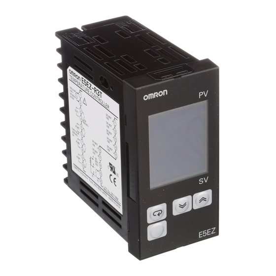
На рис. 1 показан внешний вид регулятора температурыOMRON E5CN. Пояснения к позиционным обозначениям рис. 1 даны в табл. 1.

Рис.1. Микропроцессорный регулятор температуры OMRON E5CN
Если для этого параметра выбрана единица «°С», тоВыводится «С»; при выборе «°F» выводится» F «.
Тревога1. Загорается, если включён выход тревоги1.
Тревога2. Загорается, если включён выход тревоги2.
Вывод сигнала тревоги при сгорании нагревателя.
Загорается при обнаружении сгорания нагревателя
Загорается, если включёнуправляющий выход1 и/илиуправляющий выход2.
СТОП. Загорается, если остановлено управлениеE5CN. Во время управления этот индикатор загорается послеостанова события или функции запуска/останова. Востальных случаях этот индикатор не горит.
Управление записью при обмене данными. Загорается, если запись разрешена, и гаснет, если— запрещена.
Выводит значение измеряемой величины или типпараметра.
Выводит рабочую точку, рабочую переменную илизаданное значение(установку) параметра.


Клавиша«вниз». При каждом нажатии этой клавишиосуществляется уменьшение значений, выводимых надисплейSV.

Клавиша«вверх». При каждом нажатии этой клавишиосуществляется увеличение значений, выводимых надисплейSV.
В табл.2 представлены общие характеристики регулятора температурыOMRON E5CN
Термопара: K, J, T, E, L, U, N, R, S, B
Платиновый термометр сопротивления: Pt100, JPt100
Бесконтактный термодатчик: От К10 до70 0 С,от К60 до120 0 С, от К115 до165 0 С, от К160 до 260 0 С Вход напряжения: От 0 до 50 мВ.
Выход реле: SPST-NO, 250 B AC, 3 A (активная нагрузка)
SPST-NO, 250 B AC, 1 A (активная нагрузка).
переменное включение/выключение выхода
На рис. 2 дана схема подключения входных и выходных сигналов, а такжепитания к контроллеру OMRON E5CN.
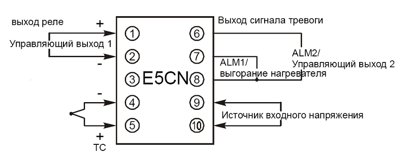
Рис. 2. Схема подключения входных и выходных сигналов контроллера
Источник питания подключается к клеммам9 и10. Клеммы 1 и2 предназначены для подключения управляющего выхода. Выход сигнала тревоги1 (ALM1) расположен на клеммах7 и8, а выход сигнала тревоги2 (ALM2) — на клеммах6 и 8. При использовании регулирования нагреванием и охлаждением выход сигнала тревоги2 может быть использован как выходом охлаждения. Чтобы отключить выход сигнала тревоги1 и обеспечить выход только сигнала тревоги выгорания нагревателя на клеммах7 и8, необходимо установить режим выхода сигнала тревоги1 в положение0.
Общая характеристика входа температурного регулятора представлена втабл. 3, схема подключения изображена на рис. 2.
Общая характеристика выхода температурного регулятора представлена втабл. 4, схема подключения изображена на рис. 2.
10 – 70 ºC, 60 – 120 ºC, 115 – 165 ºC, 160 – 260 ºC
замыкающий релейный контакт
Максимальная: 3 А при250 В постоянного тока.
Минимальная: 10 мА при5 В постоянного тока.
механическая– минимум10.000.000 операций
электрическая– минимум100.000 операций
Регулятор температуры OMRON E5CN поддерживает два методарегулирования: 2-ПИД-регулирование и регулирование включением/выключением.
Метод регулирования выбирается с помощью параметра «PID / ON/OFF» на «уровне начальной настройки». При выборе значения этого параметра устанавливается 2-ПИД-регулирование, а при выборе значения — регулирование включением/выключением(по умолчанию):
— Регулирование включением/выключением (ON/OFF). При использованииРегулирования ON/OFF управляющий выход включается (ON), если текущее значение измеряемой величины ниже заданной точки. Управляющий выход выключается(OFF), если текущее значение измеряемой величины выше заданной точки;
— 2-ПИД-регулирование. Настройка производится с помощью АТ(автоматической настройки), ST (самонастройки) и ручной настройки. Для настройки ПИД-регулирования необходимо задать константы ПИД в параметрах «пропорциональная часть (Р)», «время интегрирования (I)» и «время дифференцирования(D)».
Режим ON/OFF. Двухпозиционное регулирование.При двухпозиционном регулировании (ON/OFF) управляющий выход отключается, если измеряемая в данный момент температура достигает предварительно установленной заданной точки (уставки). После того, как манипулируемаяпеременная отключается, температура начинает понижаться и регулирование снова включается. Эта операция повторяется в определённой точке (рис. 6). На этот раз значение, до которого температура должна понизиться, чтобы регулирование снова включилось, определяется параметром «гистерезис(нагрев)».
Кроме того, объём настройки манипулируемой переменной в соответствии с увеличением или уменьшением измеряемой величины определяется параметром «прямое/обратное регулирование».
При работе в режиме ON/OFF переходный процесс протекает подобно тому, который представлен на рис. 6. Текущее значение температуры поднимается выше уставки (перерегулирование)и далее качается около температуры уставки (качание).

Рис. 3. Принцип работы выхода температурного контроллера в режимеON/OFF
Переключение между регулированием2-ПИД и двухпозиционнымрегулированием (ON/OFF) выполняется с помощью параметра «PID / ON/OFF» (уровень начальной настройки). Если этот параметр установлен на «PiD» — значит выбрано регулирование2-ПИД, а при установке этого параметра на «onof» — выбирается двухпозиционное регулирование(ON/OFF). Значение по умолчанию: «onof».
Гистерезис. При двухпозиционном регулировании (ON/OFF) гистерезисиспользуется в качестве разности для переключения выхода в положение ON, когда температура отклоняется от требуемой заданной точки, а также для обеспечения стабильности вокруг заданной точки. Функции управляющего выхода «нагрев» и управляющего выхода «охлаждение» настраиваются в функциях гистерезиса «нагрев» и гистерезиса «охлаждение» соответственно.
В стандартном регулировании с помощью нагрева или охлаждения гистерезис можно настраивать только со стороны, приближающейся к заданной точке.
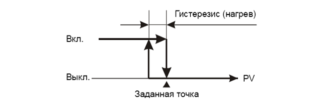
Рис. 4. Гистерезис температурного контроллера в режимеON/OFF
Трехпозиционное регулирование.При регулировании нагревом и охлаждением «мёртвую зону» (область, в которой оба управляющих выхода выключены) можно настраивать либо в сторону нагрева, либо в сторону охлаждения. Таким образом, становится возможным трёхпозиционное регулирование.

Рис. 5. Гистерезис при трехпозиционном регулировании
В табл. 5 представлены параметры режимаON/OFF.
Источник
Терморегулятор Omron e5cn инструкция на русском
Терморегуляторы Omron серии E5CN
В составе продукции торговой марки Omron компанией предлагается широкий перечень устройств для автоматического регулирования температурных режимов. Продукты представлены в большом диапазоне серий и модификаций, способных выполнять как базовые функции терморегулирования, так и решать более сложные комплексные задачи. Одна из популярных серий регуляторов температуры – серия E5CN.
Основные виды и особенности
Исходя из основного назначения и доступных функций контроллеров температуры, компания Omron предлагает следующие группы устройств:
- Базовые — производят контроль и простое дискретное регулирование параметров по типу вкл/выкл или выполняют одноконтурное ПИД регулирование;
- общего назначения — предназначены для обеспечения одноконтурного регулирования и выполнения дополнительных функций;
- высокотехнологичные — представлены одно- и двухконтурными моделями, способными работать как в составе общей системы, так и в автономном режиме; используются для решения сложных задач.
Универсальный терморегулятор Omron e5cn (инструкция +на русском языке находится в онлайн доступе) относится к устройствам общего назначения. Характеризуется простотой в установке и эксплуатации, высокой надежностью и широким функционалом. Компактный цифровой регулятор температуры имеет следующие отличительные особенности:
- дисплей с одиннадцатью сегментами повышенной функциональности;
- аналоговые выходы;
- высокую скорость преобразования аналоговых сигналов;
- упрощенную запись выходных данных;
- удобную связь с компьютерным оснащением.
Благодаря универсальности применения и совокупности приведенных выше качеств терморегулятор Omron e5cn (инструкция на русском языке прилагается при покупке) пользуется наибольшим спросом у потребителей и занимает лидирующие позиции на мировых отраслевых рынках.
Промышленная автоматизация предполагает использование огромного количества разнопланового оборудования, устройств и компонентов. Ведущая мультибрендовая компания Олниса занимается поставками всего ряда промышленного электронного оборудования для автоматизированных систем. В числе наших предложений весь ассортимент инновационной продукции марки Omron: терморегуляторы, программируемые контроллеры, сервоприводы и многое другое.
Мы также активно взаимодействуем с более чем пятью тысячами ведущими предприятиями Европы, Азии и США. Предлагаем лучшее электронное оборудование для решения широкого круга задач. Все поставки осуществляются напрямую от производителя, что позволяет нам предлагать передовые продукты по привлекательной цене. Высокое качество, надежность и безопасность продукции подтверждаются международными и национальными сертификатами.
Дополнительные преимущества от нашей компании:
- комплексное сопровождение клиента: от первичной консультации до адресной доставки заказа;
- ориентация на разные категории производств: требующих ремонта, модернизации или вновь создаваемых; с этой целью в каталоге представлены как новейшие линейки продуктов, так и снятые с производства или бывшие в эксплуатации устройства;
- возможность оформления небольшого заказа от 50 евро; это позволяет выполнять точечный ремонт или замену вышедшего из строя элемента.
Особую ценность представляет покупка высококачественного промышленного электронного оборудования с увеличенной 18-месячной гарантией. Предложение действует на определенный перечень товаров.
Источник
Контроллер Omron e5cn инструкция
Характеристики терморегуляторов Omron серии E5CN
Средства промышленной автоматизации японского бренда Omron известны по всему миру. Наиболее известными продуктами компании считаются интеллектуальные контроллеры, высокопроизводительные ПК, программное обеспечение. Выпускает производитель и множество разнообразных датчиков нового поколения. С помощью этих устройств можно эффективно наладить работу любого современного производства. Достаточно популярной продукцией бренда Omron являются инновационные терморегуляторы. Они выпускаются производителем в разных линейках. На рынке наблюдается большой спрос на эти изделия ТМ Omron. Все дело в том, что приборы зарекомендовали себя во время эксплуатации наилучшим образом. У них оптимальное соотношение цены и качества, а управление оборудованием отличается предельной простотой и комфортом.
Терморегуляторы Omron E5CN
Оптимизировать производственное предприятие помогут высоконадежные терморегуляторы Omron E5CN. У изделий отмечены очень важные полезные качества: несложный монтаж, повышенная степень надежности, отличные эксплуатационные характеристики.
Опишем некоторые преимущества, что имеют приборы серии E5CN. Это:
- малые габариты (лицевая панель 48х48 мм);
- расширенный набор опций (некоторые модели кроме температуры регулируют также давление, расход, уровень, влажность, вес);
- наличие аналоговых входов;
- легкость управления прибором плюс есть возможность вывода информации вручную;
- высокая дискретизация (достигает 250 мс);
- оснащенность внешним входом для дистанционного управления и другие плюсы.
Оборудование имеет одиннадцати сегментный дисплей на светодиодах. Технология делает процесс считывания информации более простым и удобным.
Рассмотрим один из приборов данной серии – терморегулятор E5CN-R2MT-500. Изделие имеет способность встраиваться в переднюю панель. Это делает настройку опций легкой и более простой. Продуктивность модификации выше, чем у моделей предыдущих линеек производителя.
Опишем некоторые свойства данного терморегулятора:
- применяется для пропорционально-интегрально-дифференциальных регуляторов;
- дисплей сделан в соответствии с технологией LCD 5;
- предусмотрено крепление на панель;
- температурная область, в которой используется устройство, находится в границах от -10 до +55 градусов Цельсия;
- степень защиты лицевой панели – стандарт IP66;
- устройство моноблочное;
- диапазон напряжения – 100-240 Вольт;
- корпус имеет защиту IP20.
Изделие обладает удлиненным сроком эксплуатации. Программируется кнопками на передней панели. Также можно настроить прибор, используя специализированное ПО.
Выбрать терморегуляторы Omron у надежного поставщика
Если Вы ищете терморегуляторы Omron по приемлемой цене, оригинального производства, обратитесь в компанию Олниса. На сайте поставщика в большом разнообразии есть вся популярная продукция бренда Omron. Можно выбрать в ассортименте различные промышленные датчики, системы автоматизации, контроллеры и многие другие изделия.
На сайте компании Олниса Вы найдете импортное промышленное оборудование по демократическим расценкам. Здесь также находится полезная справочная информация о реализуемом товаре. Если Вам, к примеру, нужна на контроллер omron e5cn инструкция, эти и другие справочные сведения есть на ресурсе olnisa.ru.
Есть и другие причины сотрудничать с компанией Олниса.
Поставщик предлагает клиентам:
- доставку товара по России и странам СНГ;
- гарантию на всю купленную продукцию;
- доставку к порогу;
- удлиненную гарантию на некоторое оборудование;
- экспресс-доставку, при которой заказ выполняется сроком от 1-го дня.
Олниса – мультибрендовая компания, которая занимается поставками промышленной электроники. Компания предлагает покупателям товары в широком ассортименте от многих известных производителей Европы, США и Азии. Можно выбрать электронную продукцию от 5 тысяч и более проверенных компаний. Весь товар сертифицирован, проверен, отвечает международным стандартам качества.
Источник
Преимущества:
- Улучшенная видимость благодаря высоте символов прибл. 16 мм.
- Глубина за передней панелью: всего 60 мм.
- Простая настройка: менее 20 параметров.
- Более быстрая выборка и циклическое обновление за 250 мс.
Характеристики
| Напряжение питания | от 100 до 240 В переменного тока 50/60 Гц, 24 В переменного тока 50/60 Гц или 24 В постоянного тока |
| Диапазон рабочего напряжения | от 85% до 110% от номинального напряжения питания |
| Потребляемая мощность | прибл. 3,5 ВА (от 100 до 240 В переменного тока) Прибл. 3,5 ВА (24 В переменного тока) Прибл. 2,5 Вт (24 В постоянного тока) |
| Вход датчика | Модели с входами для термопар Термопара: K, J, T, R или S (JIS C 1602-1995, IEC60584-1) Модели с платиновыми входами для термометров сопротивления Платиновый термометр сопротивления: Pt100 (JIS C 1604-1997, IEC60751) |
| Релейный выход | SPST-NO, 250 В перем. тока, 3 А (резистивная нагрузка), электрический ресурс: 100 000 операций, минимальная применимая нагрузка: 5 В, 10 мА |
| Выходное напряжение (для управления ТТР) | Выходное напряжение: 12 В постоянного тока+25%/-15% (ПНП), макс. ток нагрузки: 21 мА, со схемой защиты от короткого замыкания |
| Тревожный выход Релейный выход | SPST-NO, 250 В перем. тока, 1 А (резистивная нагрузка), электрический ресурс: 100 000 операций, минимальная нагрузка: 5 В, 10 мА |
| Метод управления | Управление ВКЛ/ВЫКЛ или 2-ПИД-управление (с автонастройкой) |
| Метод настройки | Цифровая настройка с помощью кнопок на передней панели |
| Метод индикации | 7-сегментный цифровой дисплей и индивидуальные индикаторы Высота символов: 16,2 мм (PV) |
| Другие функции | Смещение входа температуры, запуск/остановка, функции защиты и т. д. |
| Рабочая температура окружающей среды | -от 10 до 55°C (без конденсата и обледенения)/С трехлетней гарантией:-от 10 до 50°С |
| Рабочая влажность окружающей среды | от 25% до 85% |
| Температура хранения | -от 25 до 65°C (без конденсата и обледенения) |
Типы сигналов тревоги
Выберите типы сигналов тревоги из 11 типов сигналов тревоги, перечисленных в следующей таблице
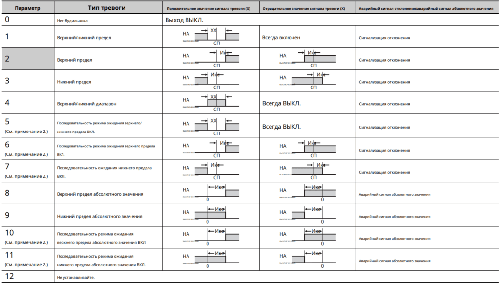
Внешние соединения
Внимание!
Выход напряжения (выход управления) электрически не изолирован от внутренних цепей. При использовании заземляющей термопары не заземляйте ни одну из управляющих выходных клемм. Если клеммы выхода управления подключены к земле, в измеренных значениях температуры возникнут ошибки из-за тока утечки.
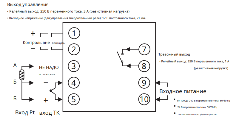
Панель управления и назначение клавиш
- Отображает значение процесса (PV) или параметр
- Отображает уставку (SP) или настройку параметра.
- Горит, когда будильник включен. Не горит, когда будильник выключен
- Горит, когда управляющий выход включен. Не горит, пока управляющий выход выключен.
- Не горит во время работы. Горит, когда работа остановлена.
- Клавиша уровня: Изменяет уровень настройки.
- Клавиша режима: Изменяет параметр в пределах уровня настройки.
- Клавиша вниз: уменьшает настройку.
- Клавиша вверх: увеличивает настройку.
- Нажимайте эти клавиши не менее 3 секунд на рабочем уровне или уровне настройки, чтобы перейти на уровень защиты. Нажмите эти клавиши и удерживайте не менее 1 секунды на уровне защиты, чтобы вернуться на рабочий уровень.
- Нажмите эти клавиши и удерживайте не менее 2 секунд, чтобы начать или остановить автонастройку.
- Нажмите эти клавиши и удерживайте не менее 2 секунд, чтобы начать или остановить операцию.
Габаритные размеры для монтажа
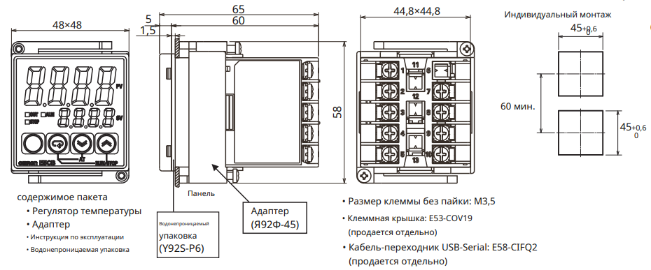
Порядок работы
Параметры
В зависимости от настроек некоторые данные могут не отображаться. Для получения подробной информации см. Инструкция по эксплуатации в файле приведенном в конце страницы.
Работа остановится, когда уровень переключится с рабочего уровня на уровень начальной настройки.
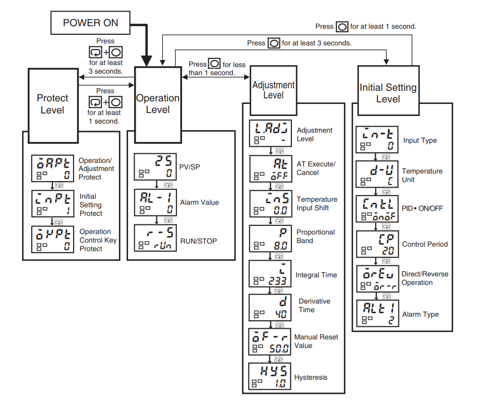
Список возможных ошибок
При возникновении ошибки на дисплее №1 отображается код ошибки. Примите необходимые меры в соответствии с кодом ошибки, сверяясь со следующей таблицей.
| Отображать | Значение | Действие |
| S.ERR | Ошибка ввода*1 | Проверьте проводку вводов, отключения, короткие замыкания и тип ввода. |
| Е111 | Ошибка оперативной памяти | Выключите питание, а затем снова включите его.*2 |
| E111/SUM | Ошибка памяти энергонезависимой памяти | нажмите |
Скачать полную инструкцию.
RU
EN

Добавить в корзину 1 шт.
на сумму 105 700 руб.
Посмотреть альтернативные предложения1
Номенклатурный номер: 8008338185
Артикул: E5CZ-Q2T AC100-240
Бренд / Производитель: Omron

Описание
Контроллер температуры (RTD, тип B, E, J, K, L, N, R, S, T, U) 100 ~ 240 В переменного тока, монтаж на панели
Технические параметры
| Control Method | On/Off, Proportional (PID) |
| Display Characters — Height | 0.433″» (11.00mm), 0.256″» (6.50mm) |
| Display Type | LCD — Dual Color Characters, Backlight |
| ECCN | EAR99 |
| Features | Option Cards Available |
| HTSUS | 9032.10.0090 |
| Ingress Protection | IP66 — Dust Tight, Water Resistant |
| Input Range | -200В°C ~ 1800В°C, 0 ~ 50mV |
| Moisture Sensitivity Level (MSL) | 1 (Unlimited) |
| Mounting Type | Panel Mount |
| Number of Characters Per Row | 4, 4 |
| Operating Temperature | -10В°C ~ 55В°C |
| Output Type | Relay (2), Voltage (External SSR) |
| Package | Bulk |
| Panel Cutout Dimensions | Square — 45.00mm x 45.00mm |
| RoHS Status | RoHS Compliant |
| Series | E5CZ -> |
| Termination Style | Screw Terminal |
| Type | Temperature Controller (RTD, Type B, E, J, K, L, N |
| Voltage — Supply | 100 ~ 240VAC |
| Weight | 0.331 lb (150.14 g) |
Техническая документация
Сроки доставки
Доставка в регион Курск
| Магазин «ЧИП и ДИП» | 7 ноября1 | бесплатно |
| ПВЗ 5Post | 7 ноября1 | бесплатно |
| ПВЗ Яндекс Доставка | 7 ноября1 | бесплатно |
| ПВЗ Boxberry | 7 ноября1 | бесплатно |
| ПВЗ Л-Пост | 7 ноября1 | бесплатно |
| ПВЗ СДЭК | 15 ноября1 | бесплатно |
| ТК DPD | 2 ноября1 | бесплатно |
| ТК «Деловые линии» | 3 ноября1 | бесплатно |
| Почта России | 14 ноября1 | бесплатно |
| Курьер | 15 ноября1 | 416 руб.2 |
Цена и наличие в магазинах
| Курск, ул. Карла Маркса, 68, ТЦ «Мега Гринн», 1 этаж |
нет в наличии |
Item
Control
Relay
output 1
Voltage
Current
Display
E5CZ/CZ-U 7-segment digital display and single-LED
method
E5AZ/EZ
Transfer output
Previous models
E5CZ-R@@@
SPST-NO, 250 VAC, 3 A (resistive load)
Electrical life: 100,000 operations.
(No models with plug-in type)
E5AZ-R@@@
SPST-NO, 250 VAC, 5 A (resistive load)
Electrical life: 100,000 operations.
E5EZ-R@@@
SPST-NO, 250 VAC, 5 A (resistive load)
Electrical life: 100,000 operations.
E5CZ-Q@@@
12 VDC ±15% (PNP)
Max. load current: 21 mA
With short-circuit protection
(No models with plug-in type)
E5AZ-Q@@@
12 VDC +15%/−20% (PNP)
Max. load current: 40 mA
With short-circuit protection
E5EZ-Q@@@
12 VDC +15%/−20% (PNP)
Max. load current: 40 mA
With short-circuit protection
E5CZ-C@@@
4 to 20 mA DC
Load: 600 Ω max.
Resolution: Approx. 2,600
E5AZ-C@@@
4 to 20 mA DC
Load: 600 Ω max.
Resolution: Approx. 2,600
E5EZ-C@@@
4 to 20 mA DC
Load: 600 Ω max.
Resolution: Approx. 2,600
indicators
7-segment digital display and single-LED
indicators
(No models with transfer outputs)
Improved models
E5CZ-R@@@@
SPST-NO, 250 VAC, 3 A (resistive load)
Electrical life: 100,000 operations.
E5CZ-R@@@U
SPDT, 250 VAC, 3 A (resistive load)
Electrical life: 100,000 operations.
E5AZ-R@@@@@
SPST-NO, 250 VAC, 5 A (resistive load)
Electrical life: 100,000 operations.
E5EZ-R@@@@@
SPST-NO, 250 VAC, 5 A (resistive load)
Electrical life: 100,000 operations.
E5CZ-Q@@@@
12 VDC ±15% (PNP)
Max. load current: 21 mA
With short-circuit protection
E5CZ-Q@@@U
12 VDC ±15% (PNP)
Max. load current: 21 mA
With short-circuit protection
E5AZ-Q@@@@@
12 VDC +15%/−20% (PNP)
Max. load current: 40 mA
With short-circuit protection
E5EZ-Q@@@@@
12 VDC +15%/−20% (PNP)
Max. load current: 40 mA
With short-circuit protection
E5CZ-C@@@@
4 to 20 mA DC,0 to 20 mA DC.
Load: 600 Ω max.
Resolution: Approx. 2,700
E5AZ-C@@@@
4 to 20 mA DC,0 to 20 mA DC.
Load: 600 Ω max.
Resolution: Approx. 2,700
E5EZ-C@@@@
4 to 20 mA DC,0 to 20 mA DC.
Load: 600 Ω max.
Resolution: Approx. 2,700
11-segment digital display and single-LED indica-
tor (Improved visibility)
(A 7-segment digital display also possible.)
11-segment digital display and single-LED indica-
tor (Improved visibility)
(A 7-segment digital display also possible.)
E5@Z-C@@@@
Allocated to current output
4 to 20 mA DC,0 to 20 mA DC.
Load: 600 Ω max.
Resolution: Approx. 2,700 (4 to 20 mA DC)
xvii