- Manuals
- Brands
- Megger Manuals
- Test Equipment
- ODEN AT
- User manual
-
Contents
-
Table of Contents
-
Troubleshooting
-
Bookmarks
Quick Links
ODEN AT
High Current System
User’s Manual
ZP-BH02E
BH0224TE
V09a
2018
Art No.
Doc.
Related Manuals for Megger ODEN AT
Summary of Contents for Megger ODEN AT
-
Page 1
ODEN AT High Current System User’s Manual ZP-BH02E BH0224TE V09a 2018 Art No. Doc. -
Page 3
© 2013-2017, Megger Sweden AB. All rights reserved. The contents of this manual are the property of Megger Sweden AB. No part of this work may be reproduced or transmitted in any form or by any means, except as permitted in written license agreement with Megger Sweden AB. Megger Sweden AB has made every reasonable attempt to ensure the completeness and accuracy of this document. -
Page 4: Table Of Contents
7.5 Setting times for limited-time generation (MAX TIME) ……….40 2.2 Fields of application ……..11 7.6 Continuous current generation ….41 2.3 Reservations ……….11 7.7 Getting maximum current from ODEN AT ..41 3 Control panel 7.8 Improving the resolution of current …………12 settings ………..42 3.1 ODEN AT control panel ……12…
-
Page 5
ODEN AT systems for 400 V …..85 11.6 Output specifications for 480 V ODEN AT systems at 60 Hz ……..90 11.7 Load curves ODEN AT systems for 480 V 60 Hz …93 11.8 Ammeter 1 ……….96 11.9 Stop input ……….97 Appendix 1 ………… -
Page 6: Safety
▪ Make certain that all personnel who work with ODEN AT have been trained in its use and that all applicable safety precautions are taken. Important ▪…
-
Page 7: Precaution Level — Danger
Never try to service ODEN AT yourself. If you open ground systems. If a voltage potential is found the casings of the current units or control unit…
-
Page 8: Precaution Level — Important
When not in use When it is not attended During electrical storms (lightning) Before cleaning Clean the ODEN AT with a moist rag. Do not use liquid or aerosol cleaning agents. Do not spill water or other liquids onto ODEN AT.
-
Page 9
2 INTRODUCTION BH0224TE ZP-BH02E ODEN AT… -
Page 10: Introduction
It is not necessary to clear the display first. operations so that they all start at the current’s zero- ▪ You can save different settings for ODEN AT in ten cross-over points. This ensures minimized DC offset in different memories.
-
Page 11: Fields Of Application
ODEN AT is primarily intended for: only for temporary (short-duration) current genera- ▪ Testing of protective relay equipment (primary injection tion. Do not use ODEN AT for long-term generation at testing). full current. See the product specifications in chapter ▪…
-
Page 12: Control Panel
➊ ❸ ❹ 3.1 ODEN AT control panel TEST CURRENT block This chapter presents an overview of the ODEN AT control panel. The control panel is divided into a num- ber of blocks: TEST CURRENT CURRENT ADJUST VOLTMETER AND A-METER…
-
Page 13
The USB-port is used when you want to transfer test results from ODEN AT to a PC. See appendix 1. former. You can make your settings using the <V/A METER>… -
Page 14
«11.8 Ammeter 1» on page 96 Note Changing the coarse setting during genera- tion will make the stop input to latch. ODEN AT is set to respond to the opening or closing of an Voltage mode external contact. The input responds to application or interrup- tion of voltage. -
Page 15
This menu option enables you to recall or save settings for ODEN AT in 10 memories. See section 5.3. APPLICATION In this menu option can you set ODEN AT for the fol- lowing applications: In this block you can select special functions and ▪… -
Page 16: Side Panel
Generation of a pulse train. The APPLICATION menu option is described further in section 5.3. The different applications are described in detail in chapter 7 ”How to use ODEN AT” and in chapter 8 ”Application examples”. DISPLAY block The 240 V model.
-
Page 17
4 DISPLAY BH0224TE ZP-BH02E ODEN AT… -
Page 18: Display
The directional indicators that appear on the dis- ▪ Presents measured values. play show which direction you can scroll using the ▪ Presents ODEN AT´s settings. <CHANGE> knob. There are three types of directional markers: ▪ Guides you by providing helpful messages, warnings and prompts.
-
Page 19
5 MENU OPTIONS BH0224TE ZP-BH02E ODEN AT… -
Page 20: Menu Options
<AMMETER> menu option. In the <V/A METER> display. menu option you can set ODEN AT’s second ammeter You can only select a menu option while ODEN AT is (A-METER 2) and ODEN AT’s voltmeter. In the <SYS- in the OFF state (i.e. not generating).
-
Page 21
In this menu option you can make settings for Menu Settings Description ODEN AT’s first ammeter (A-METER 1). You can select A-Meter 2, Auto Range is selected automatically. the range and the unit in which the reading is to be… -
Page 22: Memory And Application Menu Options
In the <MEMORY> menu option, you can store pre- hh:mm Time displayed in hours, minutes sent settings in one of ODEN AT’s 10 memories, or re- and seconds. Seconds are displayed call previously stored settings. In the <APPLICATION> up to 1 min.
-
Page 23
Turn the <CHANGE>-knob until the number of the desired memory appears. Press <ENTER>. APPLICATION In this menu option you can change ODEN AT’s mode of operation for different types of tests. The available settings are listed in the table below. Application… -
Page 24: How To Install Oden At
6.2 Loading ODEN AT onto a carriage DANGER The components of ODEN AT (i.e. the control unit and When you are changing the connec- the current units) can be mounted on a carriage for tions make sure that current not can easy transportation.
-
Page 25: Connecting The Test Object And The Current Units To Each Other
When you connect ODEN AT to the object being test- ed, you should check that the contacts on the connec- tors are clean and that the cable clamps are placed as close together as possible on the object being tested.
-
Page 26: Series Connection (Output High I)
6 HOW TO INSTALL ODEN AT 6.4 Series connection units, you can connect them either in series or in par- allel. The different connection variants are explained (output HIGH I) later in this chapter. Use series connection when you want a high voltage Do not connect units that are of different at a high load impedance.
-
Page 27: Parallel Connection (Output High I)
6 HOW TO INSTALL ODEN AT 6.5 Parallel connection 6.6 Low-current output (output HIGH I) (output 0-30V/60V) Use parallel connection when you need a low internal DANGER impedance in order to be able go generate high cur- The voltage at the output terminals rent.
-
Page 28: Connecting Current Units To The Control Unit
Fig 6.7 Current units connected to control unit If you want to connect an old current unit with a 16- pin connector to the control unit in an ODEN AT, you must use a separately-ordered adapter. Fig 6.8 ODEN AT connected to ground…
-
Page 29: Connecting Oden At To The Mains
6.10 Mains power supply the mains Mains voltage ODEN AT is designed either for 240 V, 400 V or 480 V. Important The 480 V version is for 60 Hz only. ODEN AT by itself Make sure that the mains voltage cor-…
-
Page 30: Current Cables And Conductors
6 HOW TO INSTALL ODEN AT 6.11 Current cables and conductors Available cable sets Please note: ▪ How important it is to twist the cables if possible. Values Connector on a control unit for 480 V stated for twisted cables presuppose that each cable is twisted over the entire length.
-
Page 31: Standard Multi-Cable Sets
At each end there is an end-bar interconnect- ing the cables. The bar also enables single bolt connection to ODEN AT and the test object. See figure below. Impedance of the cable set is very dependent on how cables are arranged. See section How to arrange the cable sets Length 2 x 0.5 m (distance to test object 0.5 m)
-
Page 32: Multi-Cable Sets With Customised Length
6 HOW TO INSTALL ODEN AT 6.13 Multi-cable sets with customised length Megger can supply the Multi-cable Sets with other lengths than specified above. “L” refers to length of the set (maximum distance to the test object). Calculate the impedance…
-
Page 33: How To Arrange The Cable Sets
6 HOW TO INSTALL ODEN AT 6.14 How to arrange the cable sets Minimising impedance in cables Just increasing cross-section area helps only to a cer- tain extent. When resistance is low, the major part of the impedance is caused by the reactance. Minimising…
-
Page 34
6 HOW TO INSTALL ODEN AT ODEN AT ZP-BH02E BH0224TE… -
Page 35: How To Arrange Bars
6 HOW TO INSTALL ODEN AT 6.15 How to arrange bars 6.16 To get equal current from all current units Copper-bars are in many cases a better solution than cables at high currents and short distances and at When units are connected in parallel care must be long load times.
-
Page 36: Faq
6 HOW TO INSTALL ODEN AT 6.17 FAQ Is it possible to connect ODEN AT systems in parallel or series. No. There is risk for damage since one sys- tem can feed the other backwards. Can ODEN AT supply 3-phase current.
-
Page 37
7 HOW TO USE ODEN AT BH0224TE ZP-BH02E ODEN AT… -
Page 38: How To Use Oden At
7.2 How to generate current This chapter describes the functions that you can perform using ODEN AT. Complete test procedures are Connect ODEN AT to the object under test as described in chapter 8 ”Application examples”. described in chapter 6. Safety precautions Turn on ODEN AT using the mains switch on the side of the control unit.
-
Page 39: Rules Of Thumb When Generating Current
High currents can generate a great deal of heat in current can be generated in brief intervals. It might be both ODEN AT and the object being tested. To avoid best to use manually-controlled (momentary) injection or unnecessary heating, you can: time-limited injection.
-
Page 40: Setting Times For Limited-Time Generation (Max Time)
7 HOW TO USE ODEN AT 7.5 Setting times for Repeat, starting with step 8 above, until you have set the desired current. limited-time generation Note The I/30-function is less accurate on none (MAX TIME) linear test objects. If you want to generate current throughout a limited…
-
Page 41: Continuous Current Generation
Voltage drop in mains cables and other cables. Start generation by pressing <ON+TIME>. ▪ ODEN AT’s internal impedance Set the desired current using the coarse and To obtain maximum current from ODEN AT proceed as fine adjustment procedures. follows: ▪ Connect two or three current units together.
-
Page 42: Improving The Resolution Of Current Settings
7 HOW TO USE ODEN AT 7.8 Improving the 7.9 Generating pulse trains resolution of current You can set ODEN AT to generate a pulse-train (in- termittent current generation at regular intervals, i.e. settings pulse-pause-pulse-pause etc.). This will continue until…
-
Page 43: Holding (Freezing) Measured Values
Press the <HOLD> button to activate the holding ODEN AT can display the phase angle between the (freeze) function. The function freezes a measured val- current from ODEN AT and: ue when a signal arrives at the STOP INPUT or when a) the current (I2) passing through ODEN AT’s second…
-
Page 44: Measuring Z, P, R, X, S, Q And Power Factor (Cos Φ)
Current direction is defined as illustrated in fig 7.3: Posi t i ve di r ect i on When ODEN AT’s voltmeter is activated you can measure impedance (Z), active power (P), resistance (R), reactance (X), virtual power (S), reactive power (Q) and power factor (cos ϕ).
-
Page 45: Reading Maximum Current At An
7 HOW TO USE ODEN AT 7.13 Reading maximum 7.14 Measuring operating current at an operation limits The highest current value showed on the display at There are three ways to measure operating limits: an operation is stored. Press <ESC> repeatedly until a ▪…
-
Page 46
7 HOW TO USE ODEN AT Note It is not possible to increase the current using OPERATE the coarse setting if the stop condition is set CURRENT ADJUST Close to the operating limit to INT (Internal detection will not make the… -
Page 47: Measuring Tripping/Operation Times
7 HOW TO USE ODEN AT 7.15 Measuring tripping/ 7.16 Instantaneous trip operation times unit measurement Here, generation continues until the protective relay You can test the instantaneous trip for breakers and equipment operates or the breaker trips. To avoid…
-
Page 48: Selecting Oden At Configuration And Current Cables
The ODEN AT concept has three types of current units and they can be connected in series or in parallel. So there are good possibilities to find a configuration that meet your requirements.
-
Page 49: How To Succeed In Selecting A Suitable Oden At System
Accord- ▪ ing to Ohms law I x Z volt is required to push current I Application through the impedance. If voltage at ODEN AT termi- ▪ Desired Current nals is less, current will be lower than desired.
-
Page 50
7 HOW TO USE ODEN AT ▪ 5. Select current cables / conductors Low Voltage circuit breaker rated 630 A: 0.3 — 1mΩ You know the length. Select from tables in chapter 3, ▪ Outdoor breaker pole or disconnector: ”Current cables and conductors”. -
Page 51
7 Check input current Again, to avoid surprises. ODEN AT is like a transform- er, high output power requires high input current. Your mains supply must be able to supply the current. See also Chapter 6, section 6.10 «Mains power sup- ply”… -
Page 52: Examples
ODEN AT 1/S is a possible choice. It can the line between the points. Highest possible current configuration supply 3 kA for more than 10 seconds and for an ODEN AT/3H with units in series (graph 3Hs) is has 4.0 V output voltage. 5.6 kA. Maximum allowed 3.9 V / 3 kA = 1.3 mΩ…
-
Page 53
7 HOW TO USE ODEN AT ODEN AT/1S (graph 3) 3kA at > 10 seconds Example 2, Low Voltage Circuit Breaker Conditions: Current 7 kA Cables Can not be twisted Injection time 5 seconds Breaker impedance 0.15 mΩ Current cable length 0.5 meter… -
Page 54
0.1 mΩ Distance 0.5 meter Mains voltage 400 V Selected output configura- ODEN AT 3/H with units in parallel tion can supply 15 kA for more than 5 seconds and has 2.7 V output voltage. Maximum allowed test 2.5 V / 15 kA = 0,17 mΩ… -
Page 55: Form 1
7 HOW TO USE ODEN AT Form 1 Selection of configuration & cables See explanations in chapter 7, ”Selecting ODEN AT system and current cables” Required information: Desired Current _________________ A Desired load time __________________ s_ Distance to the test object (Please check how short cables you can…
-
Page 56: Form 2
7 HOW TO USE ODEN AT Form 2 Selection of configuration when using a certain cable set Use this form when you must use a certain cable set. See explanations in chapter 7, ”Selecting ODEN AT system and current cables” Required information:…
-
Page 57
8 APPLICATION EXAMPLES BH0224TE ZP-BH02E ODEN AT… -
Page 58: Application Examples
When current first is generated for a load (while the current is being set), ODEN AT adapts itself so that all subsequent generation opera- tions start at the current’s zero-cross-over points. This ensures minimized transient DC offset when the injec- tion is initiated.
-
Page 59: Testing The Ratio Of A Current Transformer
AUTO OFF STOP INPUT er, and the current in each secondary winding is meas- STOP INPUT ured using ODEN AT’s second ammeter (A-METER 2). Start generation by pressing <ON+TIME> or <MOM ON>. WARNING Make certain that you observe all applicable…
-
Page 60: Measuring The Polarity Of A Current Transformer
P2 (H2). Basic setting: OPERATE Connect the one of the output terminals on ODEN AT’s which is marked with a dot (·) to P2 (H2) on the primary side of the CT. Connect the other output terminal to P1 (H1).
-
Page 61: Measuring The Resistances Of Circuit
Current microohms breaker, you must make certain that the circuit breaker is closed and grounded on To return ODEN AT to normal use, press the one side. <APPLICATION>-button and then turn the <CHANGE> knob until «NORMAL USE» ap- Do not measure on outdoor High Voltage pears on the display.
-
Page 62: Testing A Direct Acting Automatic Recloser
If you press <ENTER> the test results will be At time tests ODEN AT will generate current until dumped via the USB-port, see appendix 1. <OFF> is pressed or until a preset maximum genera- tion time is reached. After the cycle is completed the Press <ESC>…
-
Page 63: Testing A Sectionalizer
Total acc. You can test a sectionalizer by making appropriate 9.786Tot 2: OP time changes in ODEN AT’s settings. Here ODEN AT sends out a preset sequence of current pulses corresponding Duration Current 214ms T1 to those that would be obtained from a direct-acting…
-
Page 64: Testing A Ground Grid
8.7 Testing a ground grid The best method of testing the integrity of a ground grid is the High Current Method. An ODEN AT equipped with a current unit of type X is very suitable for this kind of tests. Here is a brief description of how such tests is conducted with ODEN AT.
-
Page 65
9 TROUBLESHOOTING BH0224TE ZP-BH02E ODEN AT… -
Page 66: Troubleshooting
ODEN AT is set for DC-Measure- DC-measurements shall only be activated if ODEN AT is equipped ment while AC is generated. (Fault with a DC-box. will be approx. 10%)
-
Page 67
• Current units are of different types. • Current unit unknown because it is uncalibrated. Unexpectively long trip- Increase INT-level or use range time while testing instan- or output with higher current taneous trip on a circuit rating. breaker BH0224TE ZP-BH02E ODEN AT… -
Page 68: Calibration
It is recommended that you calibrate Press the <SYSTEM> button. your ODEN AT system once a year, but also if a new While simultaneously pressing the but- current unit is added to your system or if the system tons <ESC>…
-
Page 69: Calibration Of Scale Factor, Ammeter 1
Press <ENTER> to confirm the calibration. Press <ESC> twice to leave the calibration menu. Scale factor, range HIGH Press the <AMMETER> menu-option and change the range to ”HIGH”. Press <ENTER> to confirm and then <AMMETER> to leave BH0224TE ZP-BH02E ODEN AT…
-
Page 70: Scale Factor For The I/30-Function
TER>. Press <V/A METER> to leave the menu. The rest of the process is just the same as for the 0 – 2 A-range, follow step 3 to 10. Cali- brate at 13 A (2/3 of the full range). ODEN AT ZP-BH02E BH0224TE…
-
Page 71: Calibration Of Scale Factor, Voltmeter
While simultaneously pressing the but- values. This also implies the settings stored in tons <ESC> and <ENTER>quickly turn the ODEN AT’s memories, which will be lost if a <CHANGE> knob clockwise until «CALIBRA- reset is performed. TION» appears on the display. Press <ENTER>…
-
Page 72: Specifications
System designation Ranges 0 – 2.000 A / 0 – 20.00 A An ODEN AT-system consists of a control unit and one, two or Voltmeter three current units. There are three different versions of the cur- rent units: S-unit (standard), X-unit (extra 30/60 V outlet) and Measurement method AC, true RMS (or DC if activated) H-unit (high current).
-
Page 73: Output Specifications For 240 V Oden At Systems At 50 Hz
11 SPECIFICATIONS 11.2 Output specifications ODEN AT/2S (240 V) for 240 V ODEN AT systems OUTPUT HIGH I — Units in PARALLEL Output (A) Voltage (V) Time on at 50 Hz Continuous 1000 Continuous Specifications are valid at nominal input voltage and…
-
Page 74
ODEN AT/3X (240 V) OUTPUT HIGH I OUTPUT HIGH I See section 11.2 ODEN AT/1S (240 V) See section 11.2 ODEN AT/3S (240 V) OUTPUT 0 – 30 V/60 V — Switch pos: 0 – 30 V OUTPUT 0 – 30 V/60 V — Switch pos: 0 – 30 V… -
Page 75
11 SPECIFICATIONS ODEN AT/2H (240 V) OUTPUT HIGH I — Units in PARALLEL Output (A) Voltage (V) Time on Continuous 2000 Continuous 2500 Continuous 4000 5 min 6000 2 min 8000 1 min 30 sec 10000 1 min 13000 2 sec… -
Page 76: Load Curves
11 SPECIFICATIONS 11.3 Load curves ODEN AT systems for 240 V OUTPUT HIGH I ODEN AT systems for 240 V at 50/60 Hz operation 4/ 5 Current (kA) ODEN AT/3S, units in SERIES ODEN AT/2S, units in SERIES ODEN AT/1S…
-
Page 77
11 SPECIFICATIONS OUTPUT HIGH I, ODEN AT systems for 240 V 3 S or X units in series 2 S or X units in series 3 S or X units in parallel 2 S or X units in parallel 1 S or X unit… -
Page 78
3 S or X units in series 2 S or X units in series 3 S or X units in parallel 2 S or X units in parallel 1 S or X unit * Voltage between the output terminals. ODEN AT ZP-BH02E BH0224TE… -
Page 79
2 H units in series 3 H units in parallel 3 H units in parallel 1 H unit 2 H units in parallel 2 H units in parallel 1 H unit * Voltage between the output terminals. BH0224TE ZP-BH02E ODEN AT… -
Page 80
11 SPECIFICATIONS OUTPUT 0-30V/60V ODEN AT systems for 240 V at 50/60 Hz operation 100 200 300 400 500 600 700 800 900 1000 1100 1200 1300 1400 1500 1600 1700 1800 1900 2000 Current (A) ODEN AT/3X 60 V, SERIES… -
Page 81
11 SPECIFICATIONS Current (A) ODEN AT/1X 30 V range ODEN AT/2X 30 V, PARALLEL ODEN AT/3X 30 V, PARALLEL ODEN AT/1X 60 V range ODEN AT/2X 30 V, SERIES ODEN AT/3X 60 V, PARALLEL ODEN AT/3X 30 V, SERIES ODEN AT/2X… -
Page 82: Output Specifications For 400 V Oden At Systems At 50 Hz
11 SPECIFICATIONS 11.4 Output specifications ODEN AT/2S (400 V) for 400 V ODEN AT systems OUTPUT HIGH I — Units in PARALLEL Output (A) Voltage (V) Time on at 50 Hz Continuous 1000 Continuous Specifications are valid at nominal input voltage and…
-
Page 83
ODEN AT/2X (400 V) OUTPUT HIGH I OUTPUT HIGH I See section 11.4. ODEN AT/1S (400 V) See section 11.4. ODEN AT/2S (400 V) OUTPUT 0 – 30 V/60 V — Switch pos: 0 – 30 V OUTPUT 0 – 30 V/60 V — Switch pos: 0 – 30 V… -
Page 84
ODEN AT/3X (400 V) ODEN AT/2H (400 V) OUTPUT HIGH I OUTPUT HIGH I — Units in PARALLEL See section 11.4 ODEN AT/3S (400 V) Output (A) Voltage (V) Time on OUTPUT 0 – 30 V/60 V — Switch pos: 0 – 30 V… -
Page 85: Load Curves
11 SPECIFICATIONS 11.5 Load curves ODEN AT systems for 400 V OUTPUT HIGH I ODEN AT systems for 400 V 50/60 Hz and 480 V 60 Hz Current (kA) ODEN AT/3S units in SERIES ODEN AT/2S units in SERIES ODEN AT/1S ODEN AT/2S…
-
Page 86
11 SPECIFICATIONS OUTPUT HIGH I, ODEN AT systems for 400 V 3 S or X units in series 2 S or X units in series 3 S or X units in parallel 1 S or X unit 2 S or X units in parallel… -
Page 87
1 H unit 2 H units in parallel 3 H units in series 2 H units in series 3 H units in parallel 1 H unit 2 H units in parallel * Voltage between the output terminals. BH0224TE ZP-BH02E ODEN AT… -
Page 88
11 SPECIFICATIONS OUTPUT 0 – 30 V/60 V ODEN AT systems for 400 V 50 Hz 5/ 6 2/ 3 100 200 300 400 500 600 700 800 900 1000 1100 1200 1300 1400 1500 1600 1700 1800 1900 2000… -
Page 89
11 SPECIFICATIONS Current (A) ODEN AT/1X 30 V range ODEN AT/2X 30 V, PARALLEL ODEN AT/3X 30 V, PARALLEL ODEN AT/1X 60 V range ODEN AT/2X 30 V, SERIES ODEN AT/3X 60 V, PARALLEL ODEN AT/3X 30 V, SERIES ODEN AT/2X… -
Page 90: Output Specifications For 480 V Oden At Systems At 60 Hz
11 SPECIFICATIONS 11.6 Output specifications ODEN AT/2S (480 V 60 Hz) for 480 V ODEN AT systems OUTPUT HIGH I — Units in PARALLEL Output (A) Voltage (V) Time on at 60 Hz Continuous 1000 Continuous Specifications are valid at nominal input voltage and…
-
Page 91
ODEN AT/2X (480 V 60 Hz) OUTPUT HIGH I OUTPUT HIGH I See section 11.4 ODEN AT/1S (480 V 60 See section 11.4 ODEN AT/2S (480 V 60 OUTPUT 0 – 30 V/60 V — Switch pos: 0 – 30 V OUTPUT 0 –… -
Page 92
11 SPECIFICATIONS ODEN AT/3X (480 V 60 Hz) ODEN AT/2H (480 V 60 Hz) OUTPUT HIGH See section 11.6 ODEN AT/3S OUTPUT HIGH I — Units in PARALLEL (480 V 60 Hz) Output (A) Voltage (V) Time on OUTPUT 0 – 30 V/60 V — Switch pos: 0 – 30 V… -
Page 93: Load Curves Oden At Systems For 480 V 60 Hz
11 SPECIFICATIONS 11.7 Load curves ODEN AT systems for 480 V 60 Hz 3 S units in series 2 S units in series 3 S units in parallel 1 S unit 2 S units in parallel BH0224TE ZP-BH02E ODEN AT…
-
Page 94
3 X units in parallel (60 V) 1 X unit (60 V) 2 X units in parallel (60 V) 3 X units in parallel (30 V) 1 X unit (30 V) 2 X units in parallel.(30 V) ODEN AT ZP-BH02E BH0224TE… -
Page 95
11 SPECIFICATIONS 3 H units in series 2 H units in series 3 H units in parallel 1 H unit 2 H units in parallel BH0224TE ZP-BH02E ODEN AT… -
Page 96: Ammeter 1
1 current unit /units in PARALLEL 480 A 0.2 A 1.5 kA 0.7 A 2 current units in SERIES 240 A 0.1 A 750 A 0.35 A 3 current units in SERIES 160 A 0.06 A 500 A 0.175 A ODEN AT ZP-BH02E BH0224TE…
-
Page 97: Stop Input
Output current with short circuited input mA DC Internal supply voltage, Vs V DC Maximum values Input voltage, DC V DC Input voltage, AC V AC rms 1) This level is needed to provide correct time readings. BH0224TE ZP-BH02E ODEN AT…
-
Page 98: Appendix 1
The transfer to a PC is made between the USB port on ODEN AT and the USB port on the PC and a com- munications program, such as the terminal program fetaured in Windows (or something similar to this).
-
Page 99: A1.3 How To Connect Via Win 2000/Xp Using The Hyper Terminal Program
For ODEN with local sw up to version R04D. (The local sw version can be seen during start up of ODEN). The Flow control shall be set to » Xon/Xoff » For ODEN with local sw from version R04G. Type in the below settings. BH0224TE ZP-BH02E ODEN AT…
-
Page 100: A1.4 Transfers In «Normal Use
APPENDIX 1 A1.4 Transfers in ”NORMAL USE” Data measured by ODEN AT will be dumped to the PC (or printer) each time you press <ENTER>. The down- loaded data contains this: ▪ Current measured by Ammeter 1 (amperes) ▪ Time (seconds) ▪…
-
Page 101: A1.5 Transfers In Applications «Test Recloser» And «Sectionalizer
Total accumulated time (seconds) ▪ Trip times and current (seconds, amperes) ▪ Reclosing times and current (seconds, amperes) Example of transferred data: 2;OP TAT; 0.673;s T01;0.397;s; 47;A R01;0.254;s; T02;0.419;s; 47;A R02;0.000;s; T03;0.000;s; R03;0.000;s; T04;0.000;s; R04;0.000;s; T05;0.000;s; R05;0.000;s; BH0224TE ZP-BH02E ODEN AT…
-
Page 102: Appendix 2
Voltmeter ranges: 0 — 0.200 V, 0 — 2.000 V, 0 -20.00 V, and 0 — 200.0 V. Ammeter range depends on the configuration used and whether current units are connected in series or parallel. See section»11.8 Ammeter 1″ on page 96. ODEN AT ZP-BH02E BH0224TE…
-
Page 103
BH0224TE ZP-BH02E ODEN AT… -
Page 104
ODEN AT ZP-BH02E BH0224TE… -
Page 105
BH0224TE ZP-BH02E ODEN AT… -
Page 106: Index
Circuit breaker resistance ……61 Generate a pulse-train ……..42 Conductors ………… 30 Generate current ……….. 38 Configuration ……….48 Generating Connect Oden AT ………. 25 Briefly …………39 Contact mode ……….14 Continuously ……….41 Control panel ……….12 CURRENT ADJUST block Limited time ……..39, 40, 46…
-
Page 107
Power factor (cos φ) ……..44 S …………..44 Power (P) ………… 44 Safety ………….. 6 Reactive power (Q) ……..44 Selecting ODEN AT system ……49 Resistance (R) ……….44 SERIES …………13 Measuring operating limits……45 Series connection ………. 26 Measuring the polarity of a current Specifications ………. -
Page 108
V/A METER ……….. 15 Virtual power (S) ……….44 Voltage drop ……….. 25, 39 Current cables ……….39 Voltage mode……….14 Win 7 or 8 …………99 Win 2000 Hyper Terminal ……99 X …………..44 Z …………..44 ODEN AT ZP-BH02E BH0224TE… -
Page 109
INDEX BH0224TE ZP-BH02E ODEN AT… -
Page 110
Megger is uniquely placed to meet the ▪ Insulation Power Factor (C&DF) Test Equipment needs of its customers worldwide. ▪ Insulation Resistance Test Equipment Megger is certified according to ISO 9001 and 14001. ▪ Line Testing Equipment Megger is a registered trademark. ▪ Low Resistance Ohmmeters Megger Group Limited ▪…
(Ocr-Read Summary of Contents of some pages of the PEWA ODEN AT Document (Main Content), UPD: 03 September 2023)
-
51, 7 H o w t o u s e O d e n A T 5 1 O d e n A T P r o g r a m m a E l e c t r i c A B Z P — B H 0 2 E R 1 0 0 5. Select current cables / conductors You know the length. Select from tables in chapter 3, ”Current cables and conductors”. • Impedance may not exceed maximum allowed value. It should be as low as possible but cable set should not be unnecessarily clumsy or heavy . • Impedance can b…
-
43, 7 H o w t o u s e O d e n A T 4 3 O d e n A T P r o g r a m m a E l e c t r i c A B Z P — B H 0 2 E R 1 0 0 7.8 Generating pulse trains You can set Oden AT to generate a pulse-train (in- termittent current generation at regular intervals, i.e. pulse-pause-pulse-pause etc.). This will continue un- til you shut off generation, until a preset maximum time (MAX TIME) is reached or until the condition at the STOP INPUT is met. 1. Basic s…
-
58, 7 H o w t o u s e O d e n A T 5 8 O d e n A T P r o g r a m m a E l e c t r i c A B Z P — B H 0 2 E R 1 0 0
… -
80, 1 1 S p e c i f i c a t i o n s 8 0 O d e n A T P r o g r a m m a E l e c t r i c A B Z P — B H 0 2 E R 1 0 0 OUTPUT HIGH I, Oden AT systems for 240 V * Voltage between the output terminals. 1 S or X unit 2 S or X units in parallel 3 S or X units in parallel 2 S or X units in series 3 S or X units in series 1 S or X unit 2 S or X units in parallel 3 S or X units in parallel 2 S or X units in series 3 S or X units in ser…
-
12, 1 S a f e t y p r e c a u t i o n s 1 2 O d e n A T P r o g r a m m a E l e c t r i c A B Z P — B H 0 2 E R 1 0 0
… -
93, PEWA ODEN AT 1 1 S p e c i f i c a t i o n s 9 3 O d e n A T P r o g r a m m a E l e c t r i c A B Z P — B H 0 2 E R 1 0 0 OUTPUT 0 – 30 V/60 V — Switch pos: 0 – 60 V Output (A) Voltage (V) Time on 0 72 Continuous 80 65 Continuous 150 61 3 min 300 52 12 sec 400 45 8 sec 600 27 2 sec Input current: Output current/6.7 (approximate) Oden AT/2X (480 V 60 Hz) OUTPUT HIGH I See section 11.4 Oden AT/2S (480 V 60 Hz) OUTPUT 0 – 30…
-
27, PEWA ODEN AT 6 H o w t o i n s t a l l O d e n A TO d e n A T P r o g r a m m a E l e c t r i c A B Z P — B H 0 2 E R 1 0 0 2 7 6.1 Safety DANGER When you are changing the connections make sure that current not can be gener- ated accidently. Disconnect the mains supply or switch the miniature breaker F2 to the 0-position. WARNING The current output terminals and con- necting points can be hot aft…
-
59, 8 A p p l i c a t i o n e x a m p l e s 5 9 O d e n A T P r o g r a m m a E l e c t r i c A B Z P — B H 0 2 E R 1 0 0 This chapter explanis step-by-step how some spe- cific objects are tested. The following are discussed: • Testing a low-voltage circuit breaker • Testing the turns ratio of a current transformer • Testing the polarity of a current transformer • Measuring the resistances of breakers and electri — ca…
-
84, 1 1 S p e c i f i c a t i o n s 8 4 O d e n A T P r o g r a m m a E l e c t r i c A B Z P — B H 0 2 E R 1 0 0 11.4 Output specifications for 400 V Oden AT systems at 50 Hz Specifications are valid at nominal input voltage and ambient temperature +25°C, (77°F) and with the current adjustment set to 100%. The specified times refer to the maximum loading time during a single load period, they are not valid during repeat…
-
57, 7 H o w t o u s e O d e n A T 5 7 O d e n A T P r o g r a m m a E l e c t r i c A B Z P — B H 0 2 E R 1 0 0 Selection of configuration when using a certain cable set Use this form when you must use a certain cable set. See explanations in chapter 7, ”Selecting ODEN AT system and current cables” Required information: • Application _________________________________________________________________________ • Desire…
-
56, 7 H o w t o u s e O d e n A T 5 6 O d e n A T P r o g r a m m a E l e c t r i c A B Z P — B H 0 2 E R 1 0 0
… -
91, 1 1 S p e c i f i c a t i o n s 9 1 O d e n A T P r o g r a m m a E l e c t r i c A B Z P — B H 0 2 E R 1 0 0 Output voltage* (V) Current (A) OUTPUT 0 – 30 V/60 V, Oden AT systems for 400 V 50 Hz Oden AT/1X 30 V range 1 Oden AT/2X 30 V, PARALLEL 2 Oden AT/3X 30 V, PARALLEL 3 Oden AT/1X 60 V range 4 Oden AT/2X 30 V, SERIES 5 Oden AT/3X 60 V, PARALLEL 6 Oden AT/3X 30 V, SERIES 7 Oden AT/2X 60 V, SERIES 8 Oden AT/…
-
88, 1 1 S p e c i f i c a t i o n s 8 8 O d e n A T P r o g r a m m a E l e c t r i c A B Z P — B H 0 2 E R 1 0 0 OUTPUT HIGH I, Oden AT systems for 400 V * Voltage between the output terminals. 2 S or X units in parallel 1 S or X unit 3 S or X units in parallel 2 S or X units in series 3 S or X units in series 2 S or X units in parallel 1 S or X unit 3 S or X units in parallel 2 S or X units in series 3 S or X units in series
… -
28, 6 H o w t o i n s t a l l O d e n A T O d e n A T P r o g r a m m a E l e c t r i c A B Z P — B H 0 2 E R 1 0 02 8 is held in place by the steel brackets on the carriage. Place the next current unit on top of the first. Make sure that it too is held in place by the brackets. The control unit should be mounted last. When the carriage is in the working position the control un…
-
74, PEWA ODEN AT 1 0 C a l i b r a t i o n 7 4 O d e n A T P r o g r a m m a E l e c t r i c A B Z P — B H 0 2 E R 1 0 0 10.7 Resetting to preset (standardized) calibration values Instead of regular calibration a resetting function can be activated that will set the calibration values to a set of preset and standardized values. This will give an accuracy of about 1%. Resetting can never replace a regular calibration where accurate and traceable reference instrument are used, but is a quic…
-
36, 6 H o w t o i n s t a l l O d e n A T O d e n A T P r o g r a m m a E l e c t r i c A B Z P — B H 0 2 E R 1 0 03 6 6.12 How to arrange the cable sets Minimising impedance in cables Just increasing cross-section area helps only to a certain extent. When resistance is low, the major part of the impedance is caused by the reactance. Minimising the magnetic flux will reduce the reac- tance: •…
-
44, 7 H o w t o u s e O d e n A T 4 4 O d e n A T P r o g r a m m a E l e c t r i c A B Z P — B H 0 2 E R 1 0 0 7.10 Measuring phase angle and polarity Oden AT can display the phase angle between the current from Oden AT and a) the current (I2) passing through Oden AT’s second ammeter (A-METER 2) or b) the voltage (V) at the voltmeter input. Press the <ESC>-button until the sign for degrees (”°”) appears in the upper-left corner of the display. Measu…
-
83, 1 1 S p e c i f i c a t i o n s 8 3 O d e n A T P r o g r a m m a E l e c t r i c A B Z P — B H 0 2 E R 1 0 0 Output voltage* (V) Current (A) OUTPUT 0-30V/60V, Oden AT systems for 240 V at 50 Hz operation Oden AT/1X 30 V range 1 Oden AT/2X 30 V, PARALLEL 2 Oden AT/3X 30 V, PARALLEL 3 Oden AT/1X 60 V range 4 Oden AT/2X 30 V, SERIES 5 Oden AT/3X 60 V, PARALLEL 6 Oden AT/3X 30 V, SERIES 7 Oden AT/2X 60 V, SERIES 8 Oden AT/3X 60 V, SERIES 9 …
-
79, PEWA ODEN AT 1 1 S p e c i f i c a t i o n s 7 9 O d e n A T P r o g r a m m a E l e c t r i c A B Z P — B H 0 2 E R 1 0 0 11.3 Load curves, Oden AT systems for 240 V OUTPUT HIGH I, Oden AT systems for 240 V at 50/60 Hz operation 1 1 2 2 4 1 0 20 40 1 2 4 1 0 20 40 1 2 3 3 4/5 8 9 10 7 seconds m inutes h ours 1 2 3 4 5 6 7 8 9 10 11 12 13 14 15 16 17 18 19 20 4 5 6 Load time Current (kA) Oden AT/3S, units in SERIES 1 Oden AT/3H, units in SERIES 6 Oden AT/2S, units in SERIES 2 …
![]()
ODEN AT
Primary Current Injection Test System
ODEN AT
Primary Current Injection Test System
▪▪Most Advanced Primary Current Injection
Test System to simplify all types of switchgear and CT commissioning, ground grid, circuit breaker testing and more
▪▪Modular design to permit optimal user configuration of output current vs. unit size
▪▪Compact transport cart facilitates portability into switchgear rooms with limited space
▪▪Unique I/30 function allows the current to be pre-set using low current to prevent test sample heating, thus eliminating corruption of test result
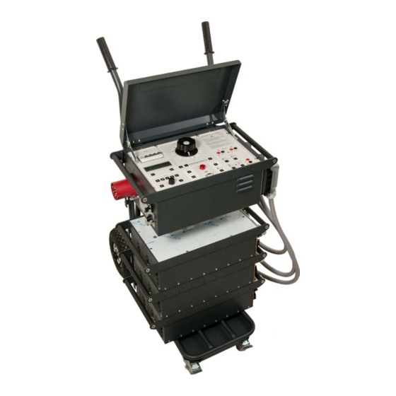
Description
This powerful test system is designed for primary injection testing of protective relay equipment and circuit breakers. It is also used to test the turns ratio of current transformers and for other applications that require high variable currents.
The system consists of a control unit together with one, two or three current units. There are three versions of the current unit: S, X and H. The S and X current units are identical except that the X unit has an additional 30/60 V output. The H unit is rated for even higher current. This makes it possible to configure an ODEN AT system in a suitable way. All parts are portable, and ODEN AT can be quickly assembled and connected.
The control unit has many advanced features – a powerful measurement section for example, that can display turns ratio as well as time, voltage and current. A second measurement channel can be used to measure an additional current or voltage. Current transformer turns ratio, impedance, resistance, power, power factor (cos φ) and phase angle are calculated and shown in the display. Current and voltage can be presented as percentages
of nominal value. The fast-acting hold function freezes shortduration readings on the digital display when the voltage or contact signal arrives at the stop input, the object under test interrupts the current or injection is stopped
Application
Primary current injection testing and breaker testing
These tests require high currents and the ability to measure very short duration, current flow. ODEN AT has been designed especially to meet these needs. No extra contacts are needed to measure the operating time of a low-voltage breaker. Testing stops at the instant when the main breaker contacts open to interrupt the current. Output current initiation is synchronized with the currents zero-crossover point to ensure good repeatability and minimized DC offset.
Testing current transformers
For turns ratio testing, the primary current and either the secondary current or the turns ratio are displayed simultaneously. Since the turns ratio is displayed directly as the nominal value (1000/5 for example), no further calculation is needed. Burden of secondary circuits can be measured and presented in VA.
Polarity testing
The currents phase displacement is shown, and the polarities of the outputs are clearly marked.
Heat runs
ODEN AT is ideal for performing heat runs. Current can be applied continuously or through programmable intervals. The times can be shown in minutes and hours which facilitates longterm testing capability.
Automatic reclosers and sectionalizers
ODEN AT can also be set to test circuit breakers with reclosing relays. Operating limits, partial times, total times and the number of operations before lockout can be measured. User-selectable reclosing sequences can be programmed for testing sectionalizers.
Testing integrity of ground grids and safety-ground devices
One way to test ground grids is by injecting current between a reference ground and the ground to be tested and measuring the voltage drop and the percentage of current flowing through the ground grid. The type X current unit included with ODEN AT is designed for this type of application. Personal safety grounds
must be tested at rated current, a task for which ODEN AT is well suited.

Features and Benefits
1.Display. The display presents time, output current, voltage, current shown on ammeter 2 and phase angle. You can scroll through entities Z, P, Q, R, X, S, power factor (cos φ) and I max.
2.Miniature circuit breaker used for current output. Interrupts output current. Can also be actuated manually for safe disconnection of load.
3.Current reduction button. Used during setting to reduce the output current to 1/30. Useful in order to avoid for example unintentional tripping and overheating.
4.Fine adjustment knob. Knob for fine adjustment of current and +/- buttons for coarse adjustment.
5.Indicator lamps. Indicate whether ammeter 2 or the voltmeter is enabled.
6.Input for voltmeter. Used to measure voltage and for microhmmeter measurement.
7.Input for ammeter 2. Used to measure current in an external circuit (in a current transformer´s secondary winding for example).
8.Hold function. This function freezes readings on the display.
9.Selection/setting (CHANGE) knob. Selects the desired menu option (shown in the display window). Also used to change numerical values.
10.Setting buttons. Personnel unfamiliar with ODEN AT can use the pre-defined settings very effectively, while experienced users can make their own basic settings.
•Ammeter. Used to set the main current-output ammeter. You can select the desired range or select autoranging.
•V/A Meter. Toggles between the voltmeter and ammeter 2. Also used to select the desired range or select autoranging.
•System. Used for general settings.
•Memory. Used to save or recall settings to or from the ten ODEN AT memories. One of these memories contains the default (pre-defined) settings that are invoked when ODEN AT is powered up.
ODEN AT
Primary Current Injection Test System
• Application. Used to invoke the desired measurement mode: automatic recloser, sectionalizer or microhmmeter.
ODEN AT can also be set to generate pulse trains with user-se- lectable pulse and pause times.
11.Injection. Starts current injection and timing.
12.Momentary Injection. When this button is used, injection continues only as long as it is pressed. Useful in order to avoid for example overheating.
13.RS232 for computer. ODEN AT is equipped with a serial port for communication with PC (for transfer of test data for example).
14.Manual shut-off. Injection and timing are stopped when this button is pressed.
15.Automatic injection stop. Generation stops after a user-spec- ified interval or when condition at the input is met. The diodes show the selected OFF condition.
16.Stop-condition indicator. Indicates that a stop condition is met, voltage or contact triggered.
17.Status indicator. Indicates if a contact connected to the input is closed or if voltage is present.
18.Stop input. Used to freeze a reading or stop injection. Activated when current is interrupted by the object being tested, when an external contact is actuated or when a voltage is applied or removed.
|
8 |
9 |
10 |
11 |
12 |
13 |
14 |
15 |
16 |
17 |
18 |

Specifications ODEN AT
Specifications are valid at nominal input voltage and an ambient temperature of +25°C, (77°F). Specifications are subject to change without notice.
System designation
An ODEN AT-system consists of a control unit and one, two or three current units. There are three different versions of the current units: S-unit (standard), X-unit (extra 30/60 V outlet) and H-unit (high current). The system designation indicates the number and version of current units included.
Example: ODEN AT/2X
2 = Number of current units
X = Version of current unit (S, X or H)
Environment
|
Application field |
The instrument is intended for use |
|
in high-voltage substations and |
|
|
industrial environments. |
|
|
Temperature |
|
|
Operating |
0°C to +50°C (+32°F to +122°F) |
|
Storage & transport |
-25°C to +55°C (-13°F to +127°F) |
|
Humidity |
5% – 95% RH, non-condensing |
|
CE-marking |
|
|
LVD |
2006/95/EC |
|
EMC |
2004/108/EC |
|
General |
|
|
Mains voltage |
240 / 400 V AC, 50 / 60 Hz |
|
480 V AC / 60 Hz |
|
|
Mains inlet |
IEC 60309-2, 63 A |
|
Input current |
Output current x open circuit voltage |
|
/ input voltage |
|
|
Protection |
The output transformer has a built-in |
|
thermal cut-out, and the primary |
|
|
side is protected by a miniature |
|
|
circuit breaker. |
|
|
Dimensions |
|
|
Control unit AT |
570 x 310 x 230 mm |
|
(22.4” x 12.2” x 9”) |
|
|
Current unit S, X H |
570 x 310 x 155 mm |
|
(22.4” x 12.2” x 6”) |
|
|
Complete with cart |
690 x 350 x 860 mm |
|
(27.2” x 13.8” x 33.9”) |
|
|
Weight |
|
|
Control unit AT |
25 kg (55 lbs) |
|
Current unit S |
42 kg (92.6 lbs) |
|
Current unit X |
45 kg (99.3 lbs) |
|
Current unit H |
49 kg (108 lbs) |
|
Cart |
11 kg (24.3 lbs) |
|
Display |
LCD |
|
Available languages |
English, German, French, Spanish, |
|
Swedish. |
ODEN AT
Primary Current Injection Test System
Measurement section
Ammeters
|
Measurement method |
AC, true RMS |
|
|
Inaccuracy |
1% of range ±1 digit |
|
|
Ammeter 1 |
||
|
Ranges |
0 |
– 4800 A / 0 –15 kA |
|
0 |
– 9600 A / 0 – 30 kA |
|
|
0 |
– 960 A / 0 – 3 kA |
|
|
Ammeter 2 |
||
|
Ranges |
0 |
– 2.000 A / 0 – 20.00 A |
|
Maximum current |
20 A (The input is not protected by |
|
|
a fuse) |
||
|
Voltmeter |
||
|
Measurement method |
AC, true RMS |
|
|
Ranges |
0 |
– 0.2 V, 0 – 2 V, 0 – 20 V, |
|
0 |
– 200 V, AUTO |
|
|
Inaccuracy |
1% of range ±1 digit |
|
|
Input resistance (Rin) |
240 kΩ (range 0 – 200 V) |
|
|
24 kΩ (other ranges) |
||
|
Dielectric withstand |
2.5 kV |
|
|
Timer |
||
|
Presentation |
In seconds, mains frequency cycles |
|
|
or hours and minutes |
||
|
Ranges |
0.000 – 999.9 s |
|
|
0 |
– 9999 cycles |
|
|
0.001 s – 99 h 59 min |
||
|
Inaccuracy |
±(1 digit + 0.01% of value) |
|
|
For the stop condition in INT-mode |
||
|
1 ms shall be added to the specified |
||
|
measurement error. |
||
|
Stop input |
||
|
Max. input voltage |
250 V AC / 275 V DC |
|
|
Phase angle |
||
|
Range |
0 |
– 359º |
|
Resolution |
1º |
|
|
Inaccuracy |
±2º (for voltage and current readings |
|
|
that are higher than 10% of the |
||
|
selected range) |
Z, P, R, X, S, Q and power factor (cos φ)
For these measurements the result is calculated using U, I and sometimes φ.
Imax
Stores highest current value that exists ≥100 ms
INT-level
Threshold indicating that current is interrupted. Can be set to 0.7% or 2.1% of Ammeter 1 range.
 Loading…
Table of Contents for PEWA ODEN AT:
-
3 C o n t r o l p a n e l 2 0 O d e n A T P r o g r a m m a E l e c t r i c A B Z P — B H 0 2 E R 1 0 0 MENU block V / A METER MENU CHANGE ENTER ES C AM- METER ME- MORY APPLI- CATION SYS- TEM In this block you can select special functions and change the settings for the measuring instruments. Press the button to the desired menu option. Use the <CHANGE> knob to select a function or alter a value. Press the <ENTER> button to confi rm your choice
-
1 1 S p e c i f i c a t i o n s 9 5 O d e n A T P r o g r a m m a E l e c t r i c A B Z P — B H 0 2 E R 1 0 0 11.7 Load curves, Oden AT systems for 480 V 60 Hz 2 S units in parallel 1 S unit 3 S units in parallel 2 S units in series 3 S units in series
-
6 H o w t o i n s t a l l O d e n A TO d e n A T P r o g r a m m a E l e c t r i c A B Z P — B H 0 2 E R 1 0 0 2 7 6.1 Safety DANGER When you are changing the connections make sure that current not can be gener- ated accidently. Disconnect the mains supply or switch the miniature breaker F2 to the 0-position. WARNING The current output terminals and con- necting points can be hot after genera- tion of high current. All current units used must also be con
-
1 S a f e t y p r e c a u t i o n s 9 O d e n A T P r o g r a m m a E l e c t r i c A B Z P — B H 0 2 E R 1 0 0 1 Safety precautions 1.1 You must read the following safety precautions thoroughly • Always follow the local safety regulations that apply to work with high-voltage equipment. • Make certain that all personnel who work with Oden AT have been trained in its use and that all applicable safety precautions are taken.
-
7 H o w t o u s e O d e n A T 5 0 O d e n A T P r o g r a m m a E l e c t r i c A B Z P — B H 0 2 E R 1 0 0 7.17 How to succeed in selecting a suitable ODEN AT system Please follow the procedure below. It implies that you first choose configuration and then suitable current cables. At the end of this chapter you will find two forms (Form 1 and Form 2) useful for the procedure. Form 2.is for cases where you must use a certain cable set
-
1 1 S p e c i f i c a t i o n s 9 8 O d e n A T P r o g r a m m a E l e c t r i c A B Z P — B H 0 2 E R 1 0 0 11.8 Ammeter 1 Measurement method: AC, true RMS value Accuracy: 1% of range Ranges: Se table below Ammeter 1 — Ranges Range LOW Measurement resolution Range HIGH Measurement resolution System with S- and X-type current units, output HIGH I 1 current unit /units in PARALLEL 4800 A 2 A 15 kA 7 A 2 current units in SERIES 2400 A 1 A 7.5 kA 3.5 3 curr ent units in SERIES
-
7 H o w t o u s e O d e n A T 5 4 O d e n A T P r o g r a m m a E l e c t r i c A B Z P — B H 0 2 E R 1 0 0 Example 2, Low Voltage Circuit Breaker Conditions: Current 7 kA Cables can not be twisted Injection time 5 seconds Breaker impedance 0.15 mΩ Current cable length 0.5 meter Mains voltage 240 V. 2. Selected output configuration ODEN AT 2/S with units in parallel can supply 7 kA for more than 5 seconds and has 3.6 V output voltage. 3. Maximum allowed test circuit impedance 3.6 V / 7 kA = 0.51
-
7 H o w t o u s e O d e n A T 5 8 O d e n A T P r o g r a m m a E l e c t r i c A B Z P — B H 0 2 E R 1 0 0
-
A p p e n d i x 2 1 0 8 O d e n A T P r o g r a m m a E l e c t r i c A B Z P — B H 0 2 E R 1 0 0
-
6 H o w t o i n s t a l l O d e n A TO d e n A T P r o g r a m m a E l e c t r i c A B Z P — B H 0 2 E R 1 0 0 2 9 rent units, you can connect them either in series or in parallel. The different connection variants are explained later in this chapter. • Do not connect units that are of different types to each other. Only connect type S units to type S
-
1 1 S p e c i f i c a t i o n s 9 7 O d e n A T P r o g r a m m a E l e c t r i c A B Z P — B H 0 2 E R 1 0 0 2 H units in parallel 1 H unit 3 H units in parallel 2 H units in series 3 H units in series
-
1 1 S p e c i f i c a t i o n s 7 7 O d e n A T P r o g r a m m a E l e c t r i c A B Z P — B H 0 2 E R 1 0 0 OUTPUT 0 – 30 V/60 V — Switch pos: 0 – 30 V Units in PARALLEL Output (A) Voltage (V) Time on 0 30 Continuous 320 28 Continuous 600 25 3 min 1200 20 12 sec 1600 17 2 sec Input current: Output current/8 (approximate) OUTPUT 0 – 30 V/60 V — Switch pos: 0 – 30 V Units in SE
-
1 1 S p e c i f i c a t i o n s 9 0 O d e n A T P r o g r a m m a E l e c t r i c A B Z P — B H 0 2 E R 1 0 0 1 1 2 2 4 1 0 20 40 1 2 4 1 0 20 40 1 5/6 2/3 8 7 seconds m inutes h ours 100 200 300 400 500 600 700 800 900 10 00 1100 12 00 13 00 1400 15 00 16 00 17 00 18 00 1900 2000 4 Load time Current (A) OUTPUT 0 – 30 V/60 V, Oden AT systems for 400 V 50 Hz Oden AT/3X 60 V, SERIES 1 Oden AT/2X 60 V, SERIES 2 Oden AT/1X 60 V range 3 Oden AT/3X 30 V, SERIES 4 Oden AT/2X 30 V, SERIES 5 Oden AT/1X 30 V
-
A p p e n d i x 2 1 0 7 O d e n A T P r o g r a m m a E l e c t r i c A B Z P — B H 0 2 E R 1 0 0 A2.1 Resistance measurement accuracy Factors that influence accuracy • Flux inducing voltage in the sense cables • High phase shift between voltage and current • Material in the test circuit that saturates or have losses • Distortion in mains voltage • Accuracy of the current and
Questions, Opinions and Exploitation Impressions:
You can ask a question, express your opinion or share our experience of PEWA ODEN AT device using right now.
Download or browse on-line these Operation & User’s Manual for PEWA ODEN AT Test Equipment.
Summary of Contents:
 |
[Page 1] PEWA ODEN AT ODEN AT High Current System User’s manual |
 |
[Page 2] PEWA ODEN AT … |
 |
[Page 3] PEWA ODEN AT 3 P r o g r a m m a E l e c t r i c A B Z P — B H 0 2 E R 1 0 0 D o c . N o : B H 0 2 2 4 K E 2 0 0 5 O D E N A T Programma Electric AB Eldarvägen 4 SE-187 75 T ÄBY S weden Tel +46 8 510 195 00 Fax +46 8 510 195 95 NO TICE … |
 |
[Page 4] PEWA ODEN AT 4 O D E N A T P r o g r a m m a E l e c t r i c A B Z P — C F 0 2 D R 1 0 0 Contents 1 Safety precautions ………………………… 9 1.1 You must read the following safety precautions thoroughly . . . . . . . . . . . . . . . . . 9 P… |
 |
[Page 5] PEWA ODEN AT 5 O D E N A T P r o g r a m m a E l e c t r i c A B Z P — C F 0 2 D R 1 0 0 7.5 Continuous current generation . . . . . . . 41 7.6 Getting maximum current from Oden AT . 42 7.7 Impr oving the resolution of current settings . . . . . . … |
 |
[Page 6] PEWA ODEN AT 6 O D E N A T P r o g r a m m a E l e c t r i c A B Z P — C F 0 2 D R 1 0 0 10 Calibration ……………………………….. 71 10.1 General . . . . . . . . . . . . . . . . . . . . . . . 71 10.2 Calibration of offset . . . . . . . . … |
 |
[Page 7] PEWA ODEN AT 7 O D E N A T P r o g r a m m a E l e c t r i c A B Z P — C F 0 2 D R 1 0 0 A1.4 Transfers in applications ”TEST RECLOSER” and ”SECTIONALIZER” . . . . . 105 Appendix 2 ………………………………… 107 A2.1 Resistance m… |
 |
[Page 8] PEWA ODEN AT 8 O D E N A T P r o g r a m m a E l e c t r i c A B Z P — C F 0 2 D R 1 0 0 |
 |
[Page 9] PEWA ODEN AT 1 S a f e t y p r e c a u t i o n s 9 O d e n A T P r o g r a m m a E l e c t r i c A B Z P — B H 0 2 E R 1 0 0 1 Safety precautions 1.1 You must read the following safety precautions thoroughly • Always follow the local safety re… |
 |
[Page 10] PEWA ODEN AT 1 S a f e t y p r e c a u t i o n s 1 0 O d e n A T P r o g r a m m a E l e c t r i c A B Z P — B H 0 2 E R 1 0 0 DANGER This equipment can be used only in elec- trical systems with single Ground. User must verify before connecting t… |
 |
[Page 11] PEWA ODEN AT 1 S a f e t y p r e c a u t i o n s 1 1 O d e n A T P r o g r a m m a E l e c t r i c A B Z P — B H 0 2 E R 1 0 0 WARNING The steel brackets mounted on the car- riage are only intended for keeping the Oden AT units in place during t… |
 |
[Page 12] PEWA ODEN AT 1 S a f e t y p r e c a u t i o n s 1 2 O d e n A T P r o g r a m m a E l e c t r i c A B Z P — B H 0 2 E R 1 0 0 |
 |
[Page 13] PEWA ODEN AT 2 I n t r o d u c t i o n 1 3 P r o g r a m m a E l e c t r i c A B Z P — B H 0 2 E R 1 0 0 O d e n A T 2 Introduction can be connected either in series or in parallel to the 0-30V/60V output, providing either a 30 V or a 60 V output. F… |
 |
[Page 14] PEWA ODEN AT 2 I n t r o d u c t i o n 1 4 P r o g r a m m a E l e c t r i c A B Z P — B H 0 2 E R 1 0 0 O d e n A T • An additional channel for measuring a voltage or a second current. • Direct display of the turns ratio of a current transfo… |
 |
[Page 15] PEWA ODEN AT 2 I n t r o d u c t i o n 1 5 P r o g r a m m a E l e c t r i c A B Z P — B H 0 2 E R 1 0 0 O d e n A T 2.3 Reservations When set at maximum current, Oden AT is designed only for temporary (short-duration) current genera- tion. Do not us… |
 |
[Page 16] PEWA ODEN AT 2 I n t r o d u c t i o n 1 6 P r o g r a m m a E l e c t r i c A B Z P — B H 0 2 E R 1 0 0 O d e n A T |
 |
[Page 17] PEWA ODEN AT 3 C o n t r o l p a n e l 1 7 O d e n A T P r o g r a m m a E l e c t r i c A B Z P — B H 0 2 E R 1 0 0 3 Control panel 3.1 Oden AT control panel This chapter presents an overview of the Oden AT control panel. The control panel is divi… |
 |
[Page 18] PEWA ODEN AT 3 C o n t r o l p a n e l 1 8 O d e n A T P r o g r a m m a E l e c t r i c A B Z P — B H 0 2 E R 1 0 0 CURRENT ADJUST block CURRENT ADJUS T 1 2 3 4 5 6 7 8 9 COARSE — I/30 0 10 20 30 40 50 60 70 80 90 100 FINE In this block you set … |
 |
[Page 19] PEWA ODEN AT 3 C o n t r o l p a n e l 1 9 O d e n A T P r o g r a m m a E l e c t r i c A B Z P — B H 0 2 E R 1 0 0 The input responds to the interruption of volt- age or the opening of a contact. The status lamp adjacent to the connection socket… |
 |
[Page 20] PEWA ODEN AT 3 C o n t r o l p a n e l 2 0 O d e n A T P r o g r a m m a E l e c t r i c A B Z P — B H 0 2 E R 1 0 0 MENU block V / A METER MENU CHANGE ENTER ES C AM- METER ME- MORY APPLI- CATION SYS- TEM In this block you can select special funct… |
 |
[Page 21] PEWA ODEN AT 4 D i s p l a y 2 1 O d e n A T P r o g r a m m a E l e c t r i c A B Z P — B H 0 2 E R 1 0 0 4 Display for details. Directional indicators The directional indicators that appear on the dis- play show which direction you can scroll usin… |
 |
[Page 22] PEWA ODEN AT 2 2 O d e n A T4 D i s p l a y P r o g r a m m a E l e c t r i c A B Z P — B H 0 2 E R 1 0 0 |
 |
[Page 23] PEWA ODEN AT O d e n A T 2 3 P r o g r a m m a E l e c t r i c A B Z P — B H 0 2 E R 1 0 0 5 M e n u o p t i o n s 5.1 General This chapter explains the menu options available in the MENU block on the control panel and the set- tings that you can m… |
 |
[Page 24] PEWA ODEN AT O d e n A T 2 4 P r o g r a m m a E l e c t r i c A B Z P — B H 0 2 E R 1 0 0 5 M e n u o p t i o n s A-METER 1 In this menu option you can make settings for Oden AT’s first ammeter (A-METER 1). You can select the range and the un… |
 |
[Page 25] PEWA ODEN AT O d e n A T 2 5 P r o g r a m m a E l e c t r i c A B Z P — B H 0 2 E R 1 0 0 5 M e n u o p t i o n s SYSTEM In this menu option you can a) select the unit in which the timer results will be expressed, b) activate DC-measurement funct… |
 |
[Page 26] PEWA ODEN AT O d e n A T 2 6 P r o g r a m m a E l e c t r i c A B Z P — B H 0 2 E R 1 0 0 5 M e n u o p t i o n s Memory Menu Settings Description RECALL or SAVE RECALL 0 — 9 R ecalls settings from a specific memory. RECALL S tandard Recals f… |
 |
[Page 27] PEWA ODEN AT 6 H o w t o i n s t a l l O d e n A TO d e n A T P r o g r a m m a E l e c t r i c A B Z P — B H 0 2 E R 1 0 0 2 7 6.1 Safety DANGER When you are changing the connections make sure that current not can be gener- ated accidentl… |
 |
[Page 28] PEWA ODEN AT 6 H o w t o i n s t a l l O d e n A T O d e n A T P r o g r a m m a E l e c t r i c A B Z P — B H 0 2 E R 1 0 02 8 is held in place by the steel brackets on the carriage. Place the next current unit on top of the first. Make s… |
 |
[Page 29] PEWA ODEN AT 6 H o w t o i n s t a l l O d e n A TO d e n A T P r o g r a m m a E l e c t r i c A B Z P — B H 0 2 E R 1 0 0 2 9 rent units, you can connect them either in series or in parallel. The different connection variants are explain… |
 |
[Page 30] PEWA ODEN AT 6 H o w t o i n s t a l l O d e n A T O d e n A T P r o g r a m m a E l e c t r i c A B Z P — B H 0 2 E R 1 0 03 0 6.5 Parallel connection (output HIGH I) Use parallel connection when you need a low internal impedance in order t… |
 |
[Page 31] PEWA ODEN AT 6 H o w t o i n s t a l l O d e n A TO d e n A T P r o g r a m m a E l e c t r i c A B Z P — B H 0 2 E R 1 0 0 3 1 6.7 Connecting current units to the control unit Important! All current units used must be connected to the con… |
 |
[Page 32] PEWA ODEN AT 6 H o w t o i n s t a l l O d e n A T O d e n A T P r o g r a m m a E l e c t r i c A B Z P — B H 0 2 E R 1 0 03 2 6.9 Connecting Oden AT to the mains Important! Make sure that the mains voltage cor- r esponds to that specified… |
 |
[Page 33] PEWA ODEN AT 6 H o w t o i n s t a l l O d e n A TO d e n A T P r o g r a m m a E l e c t r i c A B Z P — B H 0 2 E R 1 0 0 3 3 Connector on a control unit for 400 V Connector on a control unit for 240 V 6.11 Current cables and conductors Av… |
 |
[Page 34] PEWA ODEN AT 6 H o w t o i n s t a l l O d e n A T O d e n A T P r o g r a m m a E l e c t r i c A B Z P — B H 0 2 E R 1 0 03 4 Length 2 x 0.5 m (distance to test object 0.5 m) Number of cables Total cross section area Impedance cables twi… |
 |
[Page 35] PEWA ODEN AT 6 H o w t o i n s t a l l O d e n A TO d e n A T P r o g r a m m a E l e c t r i c A B Z P — B H 0 2 E R 1 0 0 3 5 Number of cables Total cross section area Impedance, cables twisted 1) (mW) Max. current in 20 sec. Max. co… |
 |
[Page 36] PEWA ODEN AT 6 H o w t o i n s t a l l O d e n A T O d e n A T P r o g r a m m a E l e c t r i c A B Z P — B H 0 2 E R 1 0 03 6 6.12 How to arrange the cable sets Minimising impedance in cables Just increasing cross-section area helps only to… |
 |
[Page 37] PEWA ODEN AT 6 H o w t o i n s t a l l O d e n A TO d e n A T P r o g r a m m a E l e c t r i c A B Z P — B H 0 2 E R 1 0 0 3 7 |
 |
[Page 38] PEWA ODEN AT 6 H o w t o i n s t a l l O d e n A T O d e n A T P r o g r a m m a E l e c t r i c A B Z P — B H 0 2 E R 1 0 03 8 6.13 How To Arrange Bars Copper-bars are in many cases a better solution than cables at high currents and short di… |
 |
[Page 39] PEWA ODEN AT 7 H o w t o u s e O d e n A T 3 9 O d e n A T P r o g r a m m a E l e c t r i c A B Z P — B H 0 2 E R 1 0 0 This chapter describes the functions that you can perform using Oden AT. Complete test procedures are described in the n… |
 |
[Page 40] PEWA ODEN AT 7 H o w t o u s e O d e n A T 4 0 O d e n A T P r o g r a m m a E l e c t r i c A B Z P — B H 0 2 E R 1 0 0 7.2 Rules of thumb when generating current When you generate current there are rules which can be useful to follow: •… |
 |
[Page 41] PEWA ODEN AT 7 H o w t o u s e O d e n A T 4 1 O d e n A T P r o g r a m m a E l e c t r i c A B Z P — B H 0 2 E R 1 0 0 7.4 Setting times for limited-time generation (MAX TIME) If you want to generate current throughout a limited time using… |
 |
[Page 42] PEWA ODEN AT 7 H o w t o u s e O d e n A T 4 2 O d e n A T P r o g r a m m a E l e c t r i c A B Z P — B H 0 2 E R 1 0 0 7.6 Getting maximum current from Oden AT Maximum output current is limited by the follow- ing: • Impedance of the obj… |
 |
[Page 43] PEWA ODEN AT 7 H o w t o u s e O d e n A T 4 3 O d e n A T P r o g r a m m a E l e c t r i c A B Z P — B H 0 2 E R 1 0 0 7.8 Generating pulse trains You can set Oden AT to generate a pulse-train (in- termittent current generation at regular in… |
 |
[Page 44] PEWA ODEN AT 7 H o w t o u s e O d e n A T 4 4 O d e n A T P r o g r a m m a E l e c t r i c A B Z P — B H 0 2 E R 1 0 0 7.10 Measuring phase angle and polarity Oden AT can display the phase angle between the current from Oden AT and a) the… |
 |
[Page 45] PEWA ODEN AT 7 H o w t o u s e O d e n A T 4 5 O d e n A T P r o g r a m m a E l e c t r i c A B Z P — B H 0 2 E R 1 0 0 7.11 Measuring Z, P, R, X, S, Q and power factor (cos ) When Oden AT’s voltmeter is activated you can measure im… |
 |
[Page 46] PEWA ODEN AT 7 H o w t o u s e O d e n A T 4 6 O d e n A T P r o g r a m m a E l e c t r i c A B Z P — B H 0 2 E R 1 0 0 7.13 Measuring operating limits There are three ways to measure operating limits: • Normal generation. Used when there… |
 |
[Page 47] PEWA ODEN AT 7 H o w t o u s e O d e n A T 4 7 O d e n A T P r o g r a m m a E l e c t r i c A B Z P — B H 0 2 E R 1 0 0 3. Press <MOM ON> briefly. Note, however, that current must be sent out for a period longer than the operating t… |
 |
[Page 48] PEWA ODEN AT 7 H o w t o u s e O d e n A T 4 8 O d e n A T P r o g r a m m a E l e c t r i c A B Z P — B H 0 2 E R 1 0 0 7.15 Instantaneous trip unit measurement You can test the instantaneous trip for breakers and for protective relay equi… |
 |
[Page 49] PEWA ODEN AT 7 H o w t o u s e O d e n A T 4 9 O d e n A T P r o g r a m m a E l e c t r i c A B Z P — B H 0 2 E R 1 0 0 7.16 Selecting Oden AT configuration and current cables Introduction Different applications have various requirements on… |
 |
[Page 50] PEWA ODEN AT 7 H o w t o u s e O d e n A T 5 0 O d e n A T P r o g r a m m a E l e c t r i c A B Z P — B H 0 2 E R 1 0 0 7.17 How to succeed in selecting a suitable ODEN AT system Please follow the procedure below. It implies that you firs… |
 |
[Page 51] PEWA ODEN AT 7 H o w t o u s e O d e n A T 5 1 O d e n A T P r o g r a m m a E l e c t r i c A B Z P — B H 0 2 E R 1 0 0 5. Select current cables / conductors You know the length. Select from tables in chapter 3, ”Current cables and conduct… |
 |
[Page 52] PEWA ODEN AT 7 H o w t o u s e O d e n A T 5 2 O d e n A T P r o g r a m m a E l e c t r i c A B Z P — B H 0 2 E R 1 0 0 Example: An ODEN AT/3H with units in series is used and test circuit impedance is 1.2 mΩ. The line should start at 0 … |
 |
[Page 53] PEWA ODEN AT 7 H o w t o u s e O d e n A T 5 3 O d e n A T P r o g r a m m a E l e c t r i c A B Z P — B H 0 2 E R 1 0 0 7.18 Examples Example 1, Current Transformer Conditions: Current 3 kA Cables can be twisted Injection time 10 seconds … |
 |
[Page 54] PEWA ODEN AT 7 H o w t o u s e O d e n A T 5 4 O d e n A T P r o g r a m m a E l e c t r i c A B Z P — B H 0 2 E R 1 0 0 Example 2, Low Voltage Circuit Breaker Conditions: Current 7 kA Cables can not be twisted Injection time 5 seconds B… |
 |
[Page 55] PEWA ODEN AT 7 H o w t o u s e O d e n A T 5 5 O d e n A T P r o g r a m m a E l e c t r i c A B Z P — B H 0 2 E R 1 0 0 Selection of configuration & cables See explanations in chapter 7, ”Selecting ODEN AT system and current cables” … |
 |
[Page 56] PEWA ODEN AT 7 H o w t o u s e O d e n A T 5 6 O d e n A T P r o g r a m m a E l e c t r i c A B Z P — B H 0 2 E R 1 0 0 |
 |
[Page 57] PEWA ODEN AT 7 H o w t o u s e O d e n A T 5 7 O d e n A T P r o g r a m m a E l e c t r i c A B Z P — B H 0 2 E R 1 0 0 Selection of configuration when using a certain cable set Use this form when you must use a certain cable set. See expl… |
 |
[Page 58] PEWA ODEN AT 7 H o w t o u s e O d e n A T 5 8 O d e n A T P r o g r a m m a E l e c t r i c A B Z P — B H 0 2 E R 1 0 0 |
 |
[Page 59] PEWA ODEN AT 8 A p p l i c a t i o n e x a m p l e s 5 9 O d e n A T P r o g r a m m a E l e c t r i c A B Z P — B H 0 2 E R 1 0 0 This chapter explanis step-by-step how some spe- cific objects are tested. The following are discussed: • Testing … |
 |
[Page 60] PEWA ODEN AT 8 A p p l i c a t i o n e x a m p l e s 6 0 O d e n A T P r o g r a m m a E l e c t r i c A B Z P — B H 0 2 E R 1 0 0 2. Settings: HOLD: ON AUTO OFF: STOP INPUT STOP INPUT: INT 3. Start generation by pressing <ON+TIME> or &… |
 |
[Page 61] PEWA ODEN AT 8 A p p l i c a t i o n e x a m p l e s 6 1 O d e n A T P r o g r a m m a E l e c t r i c A B Z P — B H 0 2 E R 1 0 0 8.3 Measuring the polarity of a current transformer You can conduct a polarity test to determine whether or not the … |
 |
[Page 62] PEWA ODEN AT 8 A p p l i c a t i o n e x a m p l e s 6 2 O d e n A T P r o g r a m m a E l e c t r i c A B Z P — B H 0 2 E R 1 0 0 8.4 Measuring the resistances of breakers and electrical connections (microhmmeter testing) You can measure the res… |
 |
[Page 63] PEWA ODEN AT 8 A p p l i c a t i o n e x a m p l e s 6 3 O d e n A T P r o g r a m m a E l e c t r i c A B Z P — B H 0 2 E R 1 0 0 8.5 Testing a direct acting automatic recloser Setting the currrent and testing the pick-up level is done in the sam… |
 |
[Page 64] PEWA ODEN AT 8 A p p l i c a t i o n e x a m p l e s 6 4 O d e n A T P r o g r a m m a E l e c t r i c A B Z P — B H 0 2 E R 1 0 0 8.6 Testing a sectionalizer You can test a sectionalizer by making appropriate changes in Oden AT’s settings. Here… |
 |
[Page 65] PEWA ODEN AT 8 A p p l i c a t i o n e x a m p l e s 6 5 O d e n A T P r o g r a m m a E l e c t r i c A B Z P — B H 0 2 E R 1 0 0 8.7 Testing a ground grid The best method of testing the integrity of a ground grid is the High Current Method. An Od… |
 |
[Page 66] PEWA ODEN AT 8 A p p l i c a t i o n e x a m p l e s 6 6 O d e n A T P r o g r a m m a E l e c t r i c A B Z P — B H 0 2 E R 1 0 0 |
 |
[Page 67] PEWA ODEN AT 9 T r o u b l e s h o o t i n g 6 7 P r o g r a m m a E l e c t r i c A B Z P — B H 0 2 E R 1 0 0 O d e n A T 9.1 General Problem: No current is sent out from Oden AT • Check miniature circuit breaker F2. • Overheating may have tri… |
 |
[Page 68] PEWA ODEN AT 9 T r o u b l e s h o o t i n g 6 8 P r o g r a m m a E l e c t r i c A B Z P — B H 0 2 E R 1 0 0 O d e n A T 3. Press <ON+TIME> and turn the knob up to 100% and then down to 0%. 4. Connect one current unit. No load should be con-… |
 |
[Page 69] PEWA ODEN AT 9 T r o u b l e s h o o t i n g 6 9 P r o g r a m m a E l e c t r i c A B Z P — B H 0 2 E R 1 0 0 O d e n A T 9.3 Measurement errors Problem: No reading on voltmeter and am- meter 2. Possible cause: The instrument is not activated. Remed… |
 |
[Page 70] PEWA ODEN AT 9 T r o u b l e s h o o t i n g 7 0 P r o g r a m m a E l e c t r i c A B Z P — B H 0 2 E R 1 0 0 O d e n A T |
 |
[Page 71] PEWA ODEN AT 1 0 C a l i b r a t i o n 7 1 O d e n A T P r o g r a m m a E l e c t r i c A B Z P — B H 0 2 E R 1 0 0 10.1 General You can calibrate the zero levels (offset) for am- meter 1, ammeter 2 and the voltmeter. The timer in Oden AT is crystal… |
 |
[Page 72] PEWA ODEN AT 1 0 C a l i b r a t i o n 7 2 O d e n A T P r o g r a m m a E l e c t r i c A B Z P — B H 0 2 E R 1 0 0 10.3 Calibration of scale factor, ammeter 1 Scale factor, range LOW 1. Press the <AMMETER> menu-option and change the range … |
 |
[Page 73] PEWA ODEN AT 1 0 C a l i b r a t i o n 7 3 O d e n A T P r o g r a m m a E l e c t r i c A B Z P — B H 0 2 E R 1 0 0 10.5 Calibration of scale factor, ammeter 2 Scale factor, range 0 – 2 A 1. Press the <V/A METER> menu option, select ”AMM… |
 |
[Page 74] PEWA ODEN AT 1 0 C a l i b r a t i o n 7 4 O d e n A T P r o g r a m m a E l e c t r i c A B Z P — B H 0 2 E R 1 0 0 10.7 Resetting to preset (standardized) calibration values Instead of regular calibration a resetting function can be activated that… |
 |
[Page 75] PEWA ODEN AT 1 1 S p e c i f i c a t i o n s 7 5 O d e n A T P r o g r a m m a E l e c t r i c A B Z P — B H 0 2 E R 1 0 0 11 Specifications Measurement section Ammeters Measurement method AC, true RMS Inaccuracy 1% of range ±1 digit Ammeter 1 Range… |
 |
[Page 76] PEWA ODEN AT 1 1 S p e c i f i c a t i o n s 7 6 O d e n A T P r o g r a m m a E l e c t r i c A B Z P — B H 0 2 E R 1 0 0 11.2 Output specifications for 240 V Oden AT systems at 50 Hz Specifications are valid at nominal input voltage and ambient… |
 |
[Page 77] PEWA ODEN AT 1 1 S p e c i f i c a t i o n s 7 7 O d e n A T P r o g r a m m a E l e c t r i c A B Z P — B H 0 2 E R 1 0 0 OUTPUT 0 – 30 V/60 V — Switch pos: 0 – 30 V Units in PARALLEL Output (A) Voltage (V) Time on 0 30 Continuous 320 2… |
 |
[Page 78] PEWA ODEN AT 1 1 S p e c i f i c a t i o n s 7 8 O d e n A T P r o g r a m m a E l e c t r i c A B Z P — B H 0 2 E R 1 0 0 OUTPUT HIGH I — Units in SERIES Output (A) Voltage (V) Time on 0 7.3 Continuous 1250 6.7 Continuous 2000 6.3 5 min… |
 |
[Page 79] PEWA ODEN AT 1 1 S p e c i f i c a t i o n s 7 9 O d e n A T P r o g r a m m a E l e c t r i c A B Z P — B H 0 2 E R 1 0 0 11.3 Load curves, Oden AT systems for 240 V OUTPUT HIGH I, Oden AT systems for 240 V at 50/60 Hz operation 1 1 2 2 4 1 0 20 40 … |
 |
[Page 80] PEWA ODEN AT 1 1 S p e c i f i c a t i o n s 8 0 O d e n A T P r o g r a m m a E l e c t r i c A B Z P — B H 0 2 E R 1 0 0 OUTPUT HIGH I, Oden AT systems for 240 V * Voltage between the output terminals. 1 S or X unit 2 S or X units in parallel 3 S o… |
 |
[Page 81] PEWA ODEN AT 1 1 S p e c i f i c a t i o n s 8 1 O d e n A T P r o g r a m m a E l e c t r i c A B Z P — B H 0 2 E R 1 0 0 * Voltage between the output terminals. 1 H unit 2 H units in parallel 2 H units in series 3 H units in series 3 H units in para… |
 |
[Page 82] PEWA ODEN AT 1 1 S p e c i f i c a t i o n s 8 2 O d e n A T P r o g r a m m a E l e c t r i c A B Z P — B H 0 2 E R 1 0 0 1 1 2 2 4 1 0 20 40 1 2 4 1 0 20 40 1 2 3 8 7 seconds m inutes h ours 100 200 300 400 500 600 700 800 900 10 00 1100 12 00 13 0… |
 |
[Page 83] PEWA ODEN AT 1 1 S p e c i f i c a t i o n s 8 3 O d e n A T P r o g r a m m a E l e c t r i c A B Z P — B H 0 2 E R 1 0 0 Output voltage* (V) Current (A) OUTPUT 0-30V/60V, Oden AT systems for 240 V at 50 Hz operation Oden AT/1X 30 V range 1 Oden A… |
 |
[Page 84] PEWA ODEN AT 1 1 S p e c i f i c a t i o n s 8 4 O d e n A T P r o g r a m m a E l e c t r i c A B Z P — B H 0 2 E R 1 0 0 11.4 Output specifications for 400 V Oden AT systems at 50 Hz Specifications are valid at nominal input voltage and ambient… |
 |
[Page 85] PEWA ODEN AT 1 1 S p e c i f i c a t i o n s 8 5 O d e n A T P r o g r a m m a E l e c t r i c A B Z P — B H 0 2 E R 1 0 0 OUTPUT 0 – 30 V/60 V — Switch pos: 0 – 60 V Output (A) Voltage (V) Time on 0 60 Continuous 80 55 Continuous 150 5… |
 |
[Page 86] PEWA ODEN AT 1 1 S p e c i f i c a t i o n s 8 6 O d e n A T P r o g r a m m a E l e c t r i c A B Z P — B H 0 2 E R 1 0 0 Oden AT/2H (400 V) OUTPUT HIGH I — Units in PARALLEL Output (A) Voltage (V) Time on 0 3.6 Continuous 2000 3.4 Continuo… |
 |
[Page 87] PEWA ODEN AT 1 1 S p e c i f i c a t i o n s 8 7 O d e n A T P r o g r a m m a E l e c t r i c A B Z P — B H 0 2 E R 1 0 0 11.5 Load curves, Oden AT systems for 400 V OUTPUT HIGH I, Oden AT systems for 400 V 50/60 Hz and 480 V 60 Hz 1 1 1 2 2 2 3 4 4… |
 |
[Page 88] PEWA ODEN AT 1 1 S p e c i f i c a t i o n s 8 8 O d e n A T P r o g r a m m a E l e c t r i c A B Z P — B H 0 2 E R 1 0 0 OUTPUT HIGH I, Oden AT systems for 400 V * Voltage between the output terminals. 2 S or X units in parallel 1 S or X unit 3 S o… |
 |
[Page 89] PEWA ODEN AT 1 1 S p e c i f i c a t i o n s 8 9 O d e n A T P r o g r a m m a E l e c t r i c A B Z P — B H 0 2 E R 1 0 0 * Voltage between the output terminals. 3 H units in series 2 H units in series 3 H units in parallel 2 H units in parallel 1 H … |
 |
[Page 90] PEWA ODEN AT 1 1 S p e c i f i c a t i o n s 9 0 O d e n A T P r o g r a m m a E l e c t r i c A B Z P — B H 0 2 E R 1 0 0 1 1 2 2 4 1 0 20 40 1 2 4 1 0 20 40 1 5/6 2/3 8 7 seconds m inutes h ours 100 200 300 400 500 600 700 800 900 10 00 1100 12 00 … |
 |
[Page 91] PEWA ODEN AT 1 1 S p e c i f i c a t i o n s 9 1 O d e n A T P r o g r a m m a E l e c t r i c A B Z P — B H 0 2 E R 1 0 0 Output voltage* (V) Current (A) OUTPUT 0 – 30 V/60 V, Oden AT systems for 400 V 50 Hz Oden AT/1X 30 V range 1 Oden AT/2X 3… |
 |
[Page 92] PEWA ODEN AT 1 1 S p e c i f i c a t i o n s 9 2 O d e n A T P r o g r a m m a E l e c t r i c A B Z P — B H 0 2 E R 1 0 0 11.6 Output specifications for 480 V Oden AT systems at 60 Hz Specifications are valid at nominal input voltage and ambient… |
 |
[Page 93] PEWA ODEN AT 1 1 S p e c i f i c a t i o n s 9 3 O d e n A T P r o g r a m m a E l e c t r i c A B Z P — B H 0 2 E R 1 0 0 OUTPUT 0 – 30 V/60 V — Switch pos: 0 – 60 V Output (A) Voltage (V) Time on 0 72 Continuous 80 65 Continuous 150 6… |
 |
[Page 94] PEWA ODEN AT 1 1 S p e c i f i c a t i o n s 9 4 O d e n A T P r o g r a m m a E l e c t r i c A B Z P — B H 0 2 E R 1 0 0 Oden AT/2H (480 V 60 Hz) OUTPUT HIGH I — Units in PARALLEL Output (A) Voltage (V) Time on 0 4.3 Continuous 2000 4.0 Co… |
 |
[Page 95] PEWA ODEN AT 1 1 S p e c i f i c a t i o n s 9 5 O d e n A T P r o g r a m m a E l e c t r i c A B Z P — B H 0 2 E R 1 0 0 11.7 Load curves, Oden AT systems for 480 V 60 Hz 2 S units in parallel 1 S unit 3 S units in parallel 2 S units in series 3 S u… |
 |
[Page 96] PEWA ODEN AT 1 1 S p e c i f i c a t i o n s 9 6 O d e n A T P r o g r a m m a E l e c t r i c A B Z P — B H 0 2 E R 1 0 0 1 X unit (30 V) 3 X units in series (60 V) 2 X units in series (60 V) 3 X units in series (30 V) 2 X units in parallel (60 V) 2… |
 |
[Page 97] PEWA ODEN AT 1 1 S p e c i f i c a t i o n s 9 7 O d e n A T P r o g r a m m a E l e c t r i c A B Z P — B H 0 2 E R 1 0 0 2 H units in parallel 1 H unit 3 H units in parallel 2 H units in series 3 H units in series |
 |
[Page 98] PEWA ODEN AT 1 1 S p e c i f i c a t i o n s 9 8 O d e n A T P r o g r a m m a E l e c t r i c A B Z P — B H 0 2 E R 1 0 0 11.8 Ammeter 1 Measurement method: AC, true RMS value Accuracy: 1% of range Ranges: Se table below Ammeter 1 — Ranges Ran… |
 |
[Page 99] PEWA ODEN AT 1 1 S p e c i f i c a t i o n s 9 9 O d e n A T P r o g r a m m a E l e c t r i c A B Z P — B H 0 2 E R 1 0 0 11.9 Stop input This input is equipped with a 400 V voltage sup- pressor between the terminals. STOP INPUT Parameter Min Type Ma… |
 |
[Page 100] PEWA ODEN AT 1 1 S p e c i f i c a t i o n s 1 0 0 O d e n A T P r o g r a m m a E l e c t r i c A B Z P — B H 0 2 E R 1 0 0 |