-
Contents
-
Table of Contents
-
Bookmarks
Quick Links
GESTRA Steam Systems
NRR 2-2e
Betriebsanleitung 808322-01
Niveauregler NRR 2-2e
Installation and Service Instructions 808322-01
Level Controller NRR 2-2e
Instructions de montage et de mise en service 808322-01
Régulateur de niveau NRR 2-2e
Instrucciones de montaje y servicio 808322-01
Regulador de nivel NRR 2-2e
DE
Deutsch
EN
English
FR
Français
ES
Español
1
Related Manuals for GESTRA NRR 2-2e
Summary of Contents for GESTRA NRR 2-2e
-
Page 1
Niveauregler NRR 2-2e Installation and Service Instructions 808322-01 English Level Controller NRR 2-2e Instructions de montage et de mise en service 808322-01 Français Régulateur de niveau NRR 2-2e Instrucciones de montaje y servicio 808322-01 Regulador de nivel NRR 2-2e Español… -
Page 2
Wiring diagram for level controller type NRR 2-2e, level probe type NRG 21 or 26 and actuator Schéma de raccordement du régulateur de niveau type NRR 2-2e, de la sonde de niveau type NRG 21 ou 26 et de la motorisation Esquema de conexión del regulador de nivel NRR 2-2e,… -
Page 3
Gehäuse Polycarbonat, glasfaserverstärkt, schwarz. 1. 100 %-Einsteller zehn Umdrehungen nach links Frontplatte Aluminium, eloxiert. drehen. Der Niveauregler NRR 2-2e dient in Verbindung mit den Gewicht Niveausonden NRG 21 oder NRG 26 und einem elektri- 2. Umschalter Stellung schalten. Ca. 0,8 kg schen Stellventil zur kontinuierlichen Füllstandregelung. -
Page 4: Betrieb
DEUTSCH Fortsetzung Schritt 8 Betrieb Fehleranalyse Wahl des X -Faktors § Der Proportionalfaktor „X “ bestimmt die maximale Regelbetrieb Fehler: NRR 2-2 signalisiert Hochwasseralarm obwohl oder minimale Abweichung des Ist-Niveaus vom einge- nach visueller Kontrolle kein Hochwasser im Behälter 1. Umschalter Stellung schalten.
-
Page 5: Installation
Approx. 0.8 kg 5. Turn 0 % adjustor until the error-signal meter “X ” tion with the GESTRA level probe type NRG 21 or NRG 26 Dimensions shows 0 %. and a control valve with electric actuator. See Fig. 1…
-
Page 6: Operation
ENGLISH – continued – deviation “X ” will be + 10 %, viz 20 mm above the Operation Important note adjusted set point and at full load – 10 %, viz 20 mm below the adjusted set point. In this case the proportional Automatic control If the level probe is installed in a boiler external level band is 40 mm.
-
Page 7
Panneau frontal: Aluminium, anodisé. Préréglages Régulateur de niveau continu, en combinaison avec la Poids sonde de niveau GESTRA type NRG 21 ou NRG 26 et un Env. 0,8 kg robinet de réglage à motorisation électrique. Pas 1 Dimensions Réglage du point zéro (0 %) Voir Fig. -
Page 8: Avis Important
FRANÇAIS – suite – Pas 9 Manœuvre manuelle 3. Tourner le dispositif de réglage cinq fois à Réglage de la valeur de consigne 1. Mettre l’inverseur manuel / automatique en posi- gauche. L’échelle graduée du dispositif de réglage de la valeur de tion 4.
-
Page 9: Instalación
Regulador de nivel para la regulación continua de niveles, La tensión de la red es indicada en la placa de carac- Materiales en combinación con la sonda de nivel GESTRA NRG 21 o terísticas. Cuerpo: policarbonato, reforzado con fibra de vidrio, NRG 26 y una válvula de ajuste eléctrica.
-
Page 10
Para obtener una regulación sin brusquedades, el factor se produce ocasionalmente un alarma de nivel alto o § & janse a nuestra representación o sociedad GESTRA de nivel bajo (LED rojos ), deberá reducirse de «X »… -
Page 11
Esta declaración pierde su validez en caso que se realicen modificaciones en los equipos que no hayan sido acordadas con nosotros. ) NSP = Baja tensión ) EMV = Compatibilidad électromagnética Bremen, 28. April 1997 GESTRA AG Dipl.-Ing. Uwe Bledschun Dipl.-Ing. Lars Bohl Leiter Konstruktion Qualitätsbeauftragter… -
Page 12
GESTRA AG Münchener Straße 77, 28215 Bremen, Germany Telefon +49 421 3503-0, Telefax +49 421 3503-393 E-mail info@de.gestra.com, Web www.gestra.de 808322-01/798cs · 1992 GESTRA AG · Bremen · Printed in Germany…
Перейти к контенту
-
Contents
-
Table of Contents
-
Bookmarks
Quick Links
GESTRA Steam Systems
NRR 2-2e
Betriebsanleitung 808322-01
Niveauregler NRR 2-2e
Installation and Service Instructions 808322-01
Level Controller NRR 2-2e
Instructions de montage et de mise en service 808322-01
Régulateur de niveau NRR 2-2e
Instrucciones de montaje y servicio 808322-01
Regulador de nivel NRR 2-2e
DE
Deutsch
EN
English
FR
Français
ES
Español
1
Related Manuals for GESTRA NRR 2-2e
Summary of Contents for GESTRA NRR 2-2e
-
Page 1
Niveauregler NRR 2-2e Installation and Service Instructions 808322-01 English Level Controller NRR 2-2e Instructions de montage et de mise en service 808322-01 Français Régulateur de niveau NRR 2-2e Instrucciones de montaje y servicio 808322-01 Regulador de nivel NRR 2-2e Español… -
Page 2
Wiring diagram for level controller type NRR 2-2e, level probe type NRG 21 or 26 and actuator Schéma de raccordement du régulateur de niveau type NRR 2-2e, de la sonde de niveau type NRG 21 ou 26 et de la motorisation Esquema de conexión del regulador de nivel NRR 2-2e,… -
Page 3
Gehäuse Polycarbonat, glasfaserverstärkt, schwarz. 1. 100 %-Einsteller zehn Umdrehungen nach links Frontplatte Aluminium, eloxiert. drehen. Der Niveauregler NRR 2-2e dient in Verbindung mit den Gewicht Niveausonden NRG 21 oder NRG 26 und einem elektri- 2. Umschalter Stellung schalten. Ca. 0,8 kg schen Stellventil zur kontinuierlichen Füllstandregelung. -
Page 4: Betrieb
DEUTSCH Fortsetzung Schritt 8 Betrieb Fehleranalyse Wahl des X -Faktors § Der Proportionalfaktor „X “ bestimmt die maximale Regelbetrieb Fehler: NRR 2-2 signalisiert Hochwasseralarm obwohl oder minimale Abweichung des Ist-Niveaus vom einge- nach visueller Kontrolle kein Hochwasser im Behälter 1. Umschalter Stellung schalten.
-
Page 5: Installation
Approx. 0.8 kg 5. Turn 0 % adjustor until the error-signal meter “X ” tion with the GESTRA level probe type NRG 21 or NRG 26 Dimensions shows 0 %. and a control valve with electric actuator. See Fig. 1…
-
Page 6: Operation
ENGLISH – continued – deviation “X ” will be + 10 %, viz 20 mm above the Operation Important note adjusted set point and at full load – 10 %, viz 20 mm below the adjusted set point. In this case the proportional Automatic control If the level probe is installed in a boiler external level band is 40 mm.
-
Page 7
Panneau frontal: Aluminium, anodisé. Préréglages Régulateur de niveau continu, en combinaison avec la Poids sonde de niveau GESTRA type NRG 21 ou NRG 26 et un Env. 0,8 kg robinet de réglage à motorisation électrique. Pas 1 Dimensions Réglage du point zéro (0 %) Voir Fig. -
Page 8: Avis Important
FRANÇAIS – suite – Pas 9 Manœuvre manuelle 3. Tourner le dispositif de réglage cinq fois à Réglage de la valeur de consigne 1. Mettre l’inverseur manuel / automatique en posi- gauche. L’échelle graduée du dispositif de réglage de la valeur de tion 4.
-
Page 9: Instalación
Regulador de nivel para la regulación continua de niveles, La tensión de la red es indicada en la placa de carac- Materiales en combinación con la sonda de nivel GESTRA NRG 21 o terísticas. Cuerpo: policarbonato, reforzado con fibra de vidrio, NRG 26 y una válvula de ajuste eléctrica.
-
Page 10
Para obtener una regulación sin brusquedades, el factor se produce ocasionalmente un alarma de nivel alto o § & janse a nuestra representación o sociedad GESTRA de nivel bajo (LED rojos ), deberá reducirse de «X »… -
Page 11
Esta declaración pierde su validez en caso que se realicen modificaciones en los equipos que no hayan sido acordadas con nosotros. ) NSP = Baja tensión ) EMV = Compatibilidad électromagnética Bremen, 28. April 1997 GESTRA AG Dipl.-Ing. Uwe Bledschun Dipl.-Ing. Lars Bohl Leiter Konstruktion Qualitätsbeauftragter… -
Page 12
GESTRA AG Münchener Straße 77, 28215 Bremen, Germany Telefon +49 421 3503-0, Telefax +49 421 3503-393 E-mail info@de.gestra.com, Web www.gestra.de 808322-01/798cs · 1992 GESTRA AG · Bremen · Printed in Germany…
NRR 2-2e
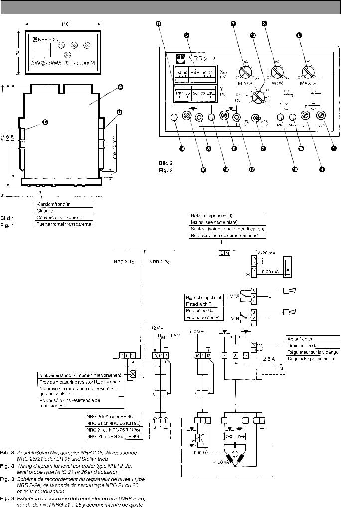
Maße / Dimensions / Dimensions / Dimensiones
B
Klarsichtfronttür
Clear lid
Couvercle transparent
Fig. 1
Puerta frontal transparente
Anschlussplan / Wiring diagram / Schéma de raccordement / Esquema de conexión
Messwiderstand R
nur einmal vorsehen!
m
Provide measuring resistor R
Ne prévoir la résistance de mesure R
Prever sólo una resistencia de medición R
Fig. 3: Anschlussplan Niveauregler NRR 2-2e,
Niveausonde NRG 26/21 oder ER 96
und Stellantrieb
Wiring diagram for level controller type NRR 2-2e,
level probe type NRG 21 or 26 and actuator
Schéma de raccordement du régulateur de niveau type NRR 2-2e,
de la sonde de niveau type NRG 21 ou 26 et de la motorisation
Esquema de conexión del regulador de nivel NRR 2-2e,
sonda de nivel NRG 21 ó 26 y accionamiento de ajuste
2
A
B
only once.
m
qu’une seule fois.
m
.
m
NRG 26/21 oder ER 96
NRG 21 or NRG 26 (ER 96)
NRG 21 ou NRG 26 (ER 96)
NRG 21 ó NRG 26 (ER 96)
!
5
$
0
8
$ 9 «
Fig. 2
Netz (siehe Typenschild)
Mains (see name plate)
Secteur (voir plaque d’identification)
Red (ver placa de características)
R
fest eingebaut
m
Fitted with R
Equipé de R
Equipado con R
7
§ 3
6
2
& % 4
m
m
m
Ablaufregler
Drain controller
Régulateur sur la vidange
Regulador por vaciado
1
Note for Owners:
Guidesimo.com webproject is not a service center of GESTRA trademark and does not carries out works for diagnosis and repair of faulty GESTRA NRR 2-2e equipment. For quality services, please contact an official service center of GESTRA company. On our website you can read and download documentation for your GESTRA NRR 2-2e device for free and familiarize yourself with the technical specifications of device.
-
Siemens SIMOTION D410
SIMOTION SIMOTION SCOUT D410 Preface Description 1 Operation (hardware) 2 Interfaces 3 Assembling 4 Connecting 5 Technical data 6 Spare parts/Accessories 7 Standards and approvals A ESD directives B SIMOTION SIMOTION SCOUT D410 Manual 05/2009 Valid for SIMOTION D410 DP and D410 PN …
SIMOTION D410 Industrial Equipment, 108
-
Danfoss ECL Comfort 310
OperatingGuideECLComfort310,applicationP3181.0TableofContents1.0TableofContents………………………………………..11.1Importantsafetyandproductinformation…………………22.0Installation………………………………………………..62.1Beforeyoustart……………………………………………..62.2Identifyingthesystemtype………………………………..182. …
ECL Comfort 310 Thermostat, 128
-
RNA ESR 2000
Rhein-Nadel Automation GmbH 1 14.04.2014 VT-BA ESR2000-GB Operating Instructions for the Control Units for Vibratory Drives Type ESR 2000 BA Rhein-Nadel Automation GmbH …
ESR 2000 Controller, 19
-
Exhausto VEX100 Series
EXHAUSTO A/SOdensevej 76DK-5550 LangeskovTel. +45 65 66 12 34Fax +45 65 66 11 [email protected]ng base, Montagesokkel, Montagesockel, Montasjesokkel, Sockel, Montageframe, Asennussokkeli.VEX140-160VEX140CF-160CFVEX240-250VEX310T-350T …
VEX100 Series Racks & Stands, 12
-
Siemens VAG61 Series
Siemens Building Technologies 74 319 0922 0 C M4212 2019-01-22 1 / 2s48 45 Z0190°4716Z1690°4211Z01122.1 VAG61..A – AB = 100 %A – AB = 0 %2.1 VBG61..A – AB = 100 %B – AB = 100 %4213Z114213Z174213Z224213Z1774 319 0922 0M4212deMontageanleitungDrehantriebenMounting instructionsRotary-type actuatorfrInstructions de montageServo-moteur à action angulairesvMonteringsinstruktionSpjällställdon …
VAG61 Series Control Unit, 2
-
Siemens SIMATIC NET MM900 Series
SIMATIC NETIndustrial Ethernet switchesMM900 media modules for SCALANCE XR-500MCompact Operating Instructions04/2022A5E03275846-05Introduction1Safety notes2Recommendations on network security3Device description4installing and removing5Connecting6Service and maintenance7Technical data8Dimension drawings9Approvals10 …
SIMATIC NET MM900 Series Switch, 48
-
S&C Scada-Mate CCU-SP
S&C Scada-Mate® Switching Systems Communication and Control UnitsTypes CCU-SP and CCU-XP Outdoor Distribution (14.4 kV through 34.5 kV)Instruction Sheet 768-550© S&C Electric Company 2001-2017, all rights reservedDecember 11, 2017Instructions for Installation, Operation, Maintenance, and CongurationTable of ContentsSection Page Section PageIntroductionQualified Persons ………….. …
Scada-Mate CCU-SP Control Unit, 29
-
Siemens Modem Block
INTRODUCTION The SIEMENS Modem Block module is a component of the HUB-4 assembly. EachModem Block module provides 1 independent data channel. The HUB-4 can supportup to 4 independent data channels. The Modem Block module mounts on the HUB-4,COM-2 board, which in turn mounts on the HUB -4 Main-2 board. Refer to the tablebelow to determine the required modules for the desired configuration.TABLE 1HU …
Modem Block Control Unit, 2
Popular Control Unit User Guides:
 Loading…
![]()
NRR 2-2e
NRR 2-2e
Betriebsanleitung 808322-01
Niveauregler NRR 2-2e
Installation and Service Instructions 808322-01
Level Controller NRR 2-2e
Instructions de montage
et de mise en service 808322-01
Régulateur de niveau NRR 2-2e
Instrucciones de montaje y servicio 808322-01
Regulador de nivel NRR 2-2e

You can only view or download manuals with
Sign Up and get 5 for free
Upload your files to the site. You get 1 for each file you add
Get 1 for every time someone downloads your manual
Buy as many as you need
Download or browse on-line these Installation And Service Instructions Manual for GESTRA NRR 2-2e Control Unit.
Summary of Contents:
 |
[Page 1] GESTRA NRR 2-2e 1 GESTRA Steam Systems NRR 2-2e Betriebsanleitung 808322-01 Niveauregler NRR 2-2e Installation and Service Instructions 808322-01 Level Controller NRR 2-2e Instructions de montage et de mise en service 808322-01 Régulateur de niveau NRR 2-2e Instruc… |
 |
[Page 2] GESTRA NRR 2-2e 2 NRR 2-2e Maße / Dimensions / Dimensions / Dimensiones Fig. 3: Anschlussplan Niveauregler NRR 2-2e, Niveausonde NRG 26/21 oder ER 96 und Stellantrieb Wiring diagram for level controller type NRR 2-2e, level probe type NRG 21 or 26 and actuato… |
 |
[Page 3] GESTRA NRR 2-2e 3 DEUTSCH Der Niveauregler NRR 2-2e dient in Verbindung mit den Niveausonden NRG 21 oder NRG 26 und einem elektri- schen Stellventil zur kontinuierlichen Füllstandregelung. Aufgabe Gefahr Niveauregler sind Sicherheitseinrichtungen und dürfen nur… |
 |
[Page 4] GESTRA NRR 2-2e 4 Achtung n Ist die Niveauelektrode in ein außenliegendes Mess- gefäß installiert, sollte vor Beginn des Abschlammens das NRR 2-2 auf Handbetrieb geschaltet werden. Nach dem Abschlammen wieder auf Automatik schalten! Regelbetrieb 1. Umschalter… |
 |
[Page 5] GESTRA NRR 2-2e 5 ENGLISH Level controller for modulating control for use in conjunc- tion with the GESTRA level probe type NRG 21 or NRG 26 and a control valve with electric actuator. Purpose Important safety notes No user serviceable parts are contained wit… |
 |
[Page 6] GESTRA NRR 2-2e 6 Important note n If the level probe is installed in a boiler external level pot, the controller should be switched over to manual control before purging the pot. Do not forget to switch back to automatic operation after purging. Automatic contr… |
 |
[Page 7] GESTRA NRR 2-2e 7 FRANÇAIS Régulateur de niveau continu, en combinaison avec la sonde de niveau GESTRA type NRG 21 ou NRG 26 et un robinet de réglage à motorisation électrique. Application Avis important pour la sécurité Comme équipement de sécurité le… |
 |
[Page 8] GESTRA NRR 2-2e 8 Avis important n Si la sonde de niveau est montée dans une bouteille extérieure, placer le régulateur en position manœuvre manuelle avant de purger la bouteille. Après la purge ne pas oublier de remettre le régulateur en position automat… |
 |
[Page 9] GESTRA NRR 2-2e 9 ESPAÑOL Regulador de nivel para la regulación continua de niveles, en combinación con la sonda de nivel GESTRA NRG 21 o NRG 26 y una válvula de ajuste eléctrica. Misión Advertencia sobre seguridad Los reguladores de nivel son equipos se seg… |
 |
[Page 10] GESTRA NRR 2-2e 10 Advertencias n Si la sonda de nivel está instalada en un recipiente de medicón exterior, antes de comenzar la purga del recipiente, debe conmutarse el regulador NRR 2-2 a funcionamiento manual. Una vez concluida la purga, no olvide de conmu… |
 |
[Page 11] GESTRA NRR 2-2e 11 Für das Gerät NRR 2-2 erklären wir die Konformität mit folgenden europäischen Richtlinien: n NSP-Richtlinie 73/23/EWG i. d. F. 93/68/EWG n EMV-Richtlinie 89/336/EWG i. d. F. 93/68/EWG Es wurden folgende harmonisierte Normen zugrunde gel… |
 |
[Page 12] GESTRA NRR 2-2e 12 808322-01/798cs · 1992 GESTRA AG · Bremen · Printed in Germany GESTRA AG Münchener Straße 77, 28215 Bremen, Germany Telefon +49 421 3503-0, Telefax +49 421 3503-393 E-mail [email protected], Web www… |
File Specifications:1897/1897480-nrr_22e.pdf file (17 Jun 2023) |
Accompanying Data:
GESTRA NRR 2-2e Control Unit PDF Installation And Service Instructions Manual (Updated: Saturday 17th of June 2023 07:48:56 AM)
Rating: 4.3 (rated by 50 users)
Compatible devices: NRS 1-40.1, ZK 313, ZK 29, Gestramat CW 41, RK Series, BK 15, BB 1 Series, TRS 5-40.
Recommended Documentation:
Installation And Service Instructions Manual (Text Version):
(Ocr-Read Summary of Contents of some pages of the GESTRA NRR 2-2e Document (Main Content), UPD: 17 June 2023)
-
1, 1 GESTRA Steam Systems NRR 2-2e Betriebsanleitung 808322-01 Niveauregler NRR 2-2e Installation and Service Instructions 808322-01 Level Controller NRR 2-2e Instructions de montage et de mise en service 808322-01 Régulateur de niveau NRR 2-2e Instrucciones de montaje y servicio 808322-01 Regulador de nivel NRR 2-2e DE Deutsch EN English FR Français ES Español
… -
2, 2 NRR 2-2e Maße / Dimensions / Dimensions / Dimensiones Fig. 3: Anschlussplan Niveauregler NRR 2-2e, Niveausonde NRG 26/21 oder ER 96 und Stellantrieb Wiring diagram for level controller type NRR 2-2e, level probe type NRG 21 or 26 and actuator Schéma de raccordement du régulateur de niveau type NRR 2-2e, de la sonde de niveau type NRG 21 ou 26 et de la motorisation Esquema de conexión del regulador de n…
-
3, 3 DEUTSCH Der Niveauregler NRR 2-2e dient in Verbindung mit den Niveausonden NRG 21 oder NRG 26 und einem elektri- schen Stellventil zur kontinuierlichen Füllstandregelung. Aufgabe Gefahr Niveauregler sind Sicherheitseinrichtungen und dürfen nur vom Hersteller repariert werden. Manipulationen oder Veränderungen am Gerät führen zu erheblichen Sicherheitsrisiken. DIN-Einschubgehäuse 1. Einschuböffnung 138 x 68 in…
-
4, GESTRA NRR 2-2e 4 Achtung n Ist die Niveauelektrode in ein außenliegendes Mess- gefäß installiert, sollte vor Beginn des Abschlammens das NRR 2-2 auf Handbetrieb geschaltet werden. Nach dem Abschlammen wieder auf Automatik schalten! Regelbetrieb 1. Umschalter 2 in Stellung schalten. 2. Die grünen LED $ signalisieren die Arbeitsweise des Reglers. Ist die Kessellast konstant, muss die Ventil- stellung ebenfalls bleiben. d. h. die LED …
-
5, 5 ENGLISH Level controller for modulating control for use in conjunc- tion with the GESTRA level probe type NRG 21 or NRG 26 and a control valve with electric actuator. Purpose Important safety notes No user serviceable parts are contained within the equipment. All repairs must be performed only by the manufacturer. Misuse or any attempted modification of the equipment will lead to considerable safety risks! DIN …
-
6, GESTRA NRR 2-2e 6 Important note n If the level probe is installed in a boiler external level pot, the controller should be switched over to manual control before purging the pot. Do not forget to switch back to automatic operation after purging. Automatic control 1. Set auto/manual switch 2 in position . 2. The green LEDs $ indicate the mode of operation of the controller. When the boiler load is constant, the valve position must also be c…
-
7, 7 FRANÇAIS Régulateur de niveau continu, en combinaison avec la sonde de niveau GESTRA type NRG 21 ou NRG 26 et un robinet de réglage à motorisation électrique. Application Avis important pour la sécurité Comme équipement de sécurité les appareils ne doivent être réparés que par le fabricant. Toute intervention ou réparation des équipements entraîne des risques consi- dérables au point de vue sécurité. Modèle à encastre…
-
8, 8 Avis important n Si la sonde de niveau est montée dans une bouteille extérieure, placer le régulateur en position manœuvre manuelle avant de purger la bouteille. Après la purge ne pas oublier de remettre le régulateur en position automatique. Manœuvre automatique 1. Mettre l’inverseur manuel / automatique 2 en posi- tion . 2. Les diodes luminescentes vertes $ indiquent le mode de fonctionnement d…
-
9, 9 ESPAÑOL Regulador de nivel para la regulación continua de niveles, en combinación con la sonda de nivel GESTRA NRG 21 o NRG 26 y una válvula de ajuste eléctrica. Misión Advertencia sobre seguridad Los reguladores de nivel son equipos se seguridad y sólo deben ser reparados por el fabricante. Manipulaciones o modificaciones del aparato dan lugar a elevados riesgos de seguridad. Caja DIN para m…
-
10, 10 Advertencias n Si la sonda de nivel está instalada en un recipiente de medicón exterior, antes de comenzar la purga del recipiente, debe conmutarse el regulador NRR 2-2 a funcionamiento manual. Una vez concluida la purga, no olvide de conmutar el regulador a regulación au- tomática. Regulación automática 1. Situar el conmutador manual/automático 2 en la posición . 2. Los LED verdes $ muestran el funcionamiento del regu…
-
11, 11 Für das Gerät NRR 2-2 erklären wir die Konformität mit folgenden europäischen Richtlinien: n NSP-Richtlinie 73/23/EWG i. d. F. 93/68/EWG n EMV-Richtlinie 89/336/EWG i. d. F. 93/68/EWG Es wurden folgende harmonisierte Normen zugrunde gelegt: n NSP-Norm EN 60947-5-1: 1991 n EMV-Normen EN 50 081-2, EN 50 082-2 Bei einer nicht mit uns abgestimmten Änderung des Gerätes verliert diese …
-
12, 12 808322-01/798cs · 1992 GESTRA AG · Bremen · Printed in Germany GESTRA AG Münchener Straße 77, 28215 Bremen, Germany Telefon +49 421 3503-0, Telefax +49 421 3503-393 E-mail [email protected], Web www.gestra.de
…
-
GESTRA NRR 2-2e User Manual
-
GESTRA NRR 2-2e User Guide
-
GESTRA NRR 2-2e PDF Manual
-
GESTRA NRR 2-2e Owner’s Manuals
Recommended: Dito 601575, 992, KC-129DS, YARD-MAN Series 556
Links & Tools
Operating Impressions, Questions and Answers:
Types of Manuals:
The main types of GESTRA NRR 2-2e instructions:
- User guide — rules of useing and characteristics
- Service manual — repair, diagnostics, maintenance
- Operation manual — description of the main functions of equipment
Control Unit Instructions by GESTRA:
-
Parker R4V Series
Bulletin MSG11-5715-661/UKOperating instructionsSeries R4V*V* / R4V*W*Series R6V*V* / R6V*W*Series DSDU*1078 E*E TÜVTranslation of German original operating instructionsSeries R4V and R6VPilot operated pressure relief valveSubplate mountedSeries DSDUPilot operated pressure relief valve2-way cartridge valvesParker Hann …
R4V Series Control Unit, 20
-
AMCI 1141
20 Gear Drive, Plymouth Industrial Park, Terryville, CT 06786 page: 1 Tel: (860) 585-1254 Fax: (860) 584-1973 Web: www.amci.com 1141 and 1142, Manual One and Two Channel 1762 I/O Resolver Interface Modules Revision 2.0 Module Overview Utilizing licensed Al …
1141 Control Unit, 22
-
Emerson unidrive m201
Power Installation GuideUnidrive M / HS Frame 7 to 10 Part Number: 0478-0234-05Issue: 5Unidrive M frame7 to 10 Power Installation Guide issue5.book Page 1 Tuesday, May 24, 2016 11:52 AM …
unidrive m201 Controller, 120
-
Panasonic KX-TD500
Features ListDigital Super Hybrid SystemQuick Reference Guidefor Single Line TelephoneModel No.KX-TD500OperationDesired FunctionMaking CallsOff-hook On-hook Feature number Talk Flash the switchhookCalling* Check number withyour dealer.RedialReceiving callsQuick DialingTo an extensionTo an external partyphone no.trunk g …
KX-TD500 Telephone, 4
-
Atmel SAM4 Series
42274A-MCU-05/2014APPLICATION NOTEAT07334: SAM4 TWI Master Mode DriverASF PROGRAMMERS MANUALSAM4 TWI Master Mode DriverThis documents describe the usage of the driver for the TWI (Two-Wire Interface)Master on the Atmel® SAM4 family of devices. It describes usage in an I2Ccompatible manner and does not provide any guid …
SAM4 Series Control Unit, 26
-
MASCOT VFlo
CAUTION :1. Use pressure relief valves for high pressure piping.2. Use explosion proof valves/accessories for dangerous media piping.3. Use fire safe valves for piping where chances of fire by external means.4. Use seismic proof valves where chances of earthquake are frequent.5. Check whether loc …
VFlo Control Unit, 8
-
Trenz Electronic TE0720
11223344D DC CB BA ADate: Page1 of 15Number:Title:GigaZee — Power03Rev.A4Copyright: 2013 Trenz Electronic GmbHTE0720.SchDocFilename:2015-10-12TE0720-14S-1CTE0720PM1 PM2PM3PM4 PM5PM6GND GNDMount.Hole 3.2mmMount.Hole 3.2mmMount.Hole 3.2mmMount.Hole 3.2mm1.5VGNDPGND2PGND3AVIN24VFB5VOUT7VOUT8AGND9AVIN110POK11ENABLE12PVIN13 …
TE0720 Control Unit, 15
-
Micro Detectors SB400M
!M.D. Micro Detectors Strada S. Caterina, 235 41122 Modena Italy Tel. +39 059 420411 Fax +39 059 253973 www.microdetectors.com [email protected]!SB400M Safety Modules LANGUAGE Installation and Operation Manual ENGLISH M.D. Micro Detectors CAT8ESB1261501 1/19 !! …
SB400M Control Unit, 19